Embed Size (px)
Citation preview

MAHARASHTRA STATE BOARD OF TECHNICAL EDUCATION (Autonomous)
(ISO/IEC - 27001 - 2005 Certified)
Summer – 16 EXAMINATION
Subject Code: 17523 Model Answer Page No: 1/18
Important Instructions to examiners:
1) The answers should be examined by key words and not as word-to-word as given in the model answer
scheme.
2) The model answer and the answer written by candidate may vary but the examiner may try to assess the
understanding level of the candidate.
3) The language errors such as grammatical, spelling errors should not be given more importance. (Not
applicable for subject English and Communication Skills).
4) While assessing figures, examiner may give credit for principal components indicated in the figure. The
figures drawn by candidate and model answer may vary. The examiner may give credit for any equivalent
figure drawn.
5) Credits may be given step wise for numerical problems. In some cases, the assumed constant values may
vary and there may be some difference in the candidate’s answers and model answer.
6) In case of some questions credit may be given by judgment on part of examiner of relevant answer based
on candidate’s understanding.
7) For programming language papers, credit may be given to any other program based on equivalent
concept. ………………………………………………………………………………………………………………………….
Marks
1. A) Attempt any three of the following: 12
a) Define: Spark ignition, auto ignition, pre ignition and surface ignition. 4
Answer: (Definition :1 mark each)
1. Spark ignition: The term spark-ignition is ignition of charge (the air-fuel mixture) by a spark
across electrodes of a spark plug.
2. Auto ignition: It is spontaneous ignition of fuel: air mixture when introduced into the
combustion chamber of an I.C. engine, as a result either of glowing carbon in the chamber or of
the heat of compression.
3. Pre-ignition: Pre-ignition is the ignition of the homogeneous mixture in the cylinder, before the
timed ignition spark occurs, caused by the local overheating of the combustible mixture.
4. Surface ignition: Surface ignition is the ignition of the fuel-air mixture by a hot spot on the
combustion chamber walls such as on overheated valve or spark plug or glowing combustion
chamber i.e. any means other than the normal spark discharge.
4
b) List the engine variables, which affect on ignition lag and flame propagation. 4
Answer: (Variables affecting Ignition lag – 2 marks & flame propagation – 2 marks)
Variables affecting Ignition lag: (four variables – 2 marks)
1. Fuel
2. Mixture Ratio.
3. Initial pressure and temperature
4. Electrode gap
5. Turbulence
Variables affecting flame propagation: (four variables – 2 marks)
1. Turbulence
2. Fuel: air ratio
3. Temperature and pressure
4. Compression ratio
2
2

MAHARASHTRA STATE BOARD OF TECHNICAL EDUCATION (Autonomous)
(ISO/IEC - 27001 - 2005 Certified)
Summer – 16 EXAMINATION
Subject Code: 17523 Model Answer Page No: 2/18
5. Engine output
6. Engine speed
7. Engine size
c) What are the effects of detonations? 4
Answer: ( Four effects – 1 mark each)
1. Noise and roughness: Mild knock is seldom audible and is not harmful. When intensity of knock
increases a loud pulsating noise is produced due to development of a pressure wave. The presence of
vibratory motion causes crankshaft vibrations and engines rough.
2. Mechanical damage: Due to rapid pressure waves, rate of wear is increased and piston head,
cylinder head and valves may be pitted.
3. Carbon deposits: Detonation results in increased carbon deposits.
4. Increase in heat transfer: Temperature in detonating engine is higher as compared to non-
detonating engine and hence scoring away the protecting layer of inactive stagnant gas. So detonation
increases the rate of heat transfer to combustion chamber walls.
5. Decrease in power output and efficiency: Due to increase in the rate of heat transfer the power
output is decreased.
6. Pre ignition: Detonation results in over heating of the sparking plug and combustion chamber wall
and this overheating leads to ignite the charge before the passage of spark.
4
d) What is meant by ignition limit for hydrocarbons in SI engines? 4
Answer: Ignition Limit: (Description:- 2 mark, Diagram:- 2 marks)
Ignition Limit corresponds approximately to that mixture ratio, at lean & rich ends of the scale,
where the heat released by spark is no longer sufficient to initiate combustion in the neighbouring
unburnt mixture. The flame will propagate only if the temperature of the burnt gases exceeds
approximately 12500 C in the case of hydrocarbon-air mixture.
The lower & upper ignition limits of the mixture depend upon mixture ratio & flame
temperature. The ignition limits are wider at increased temperature because of higher rates of reaction.
Theoretical Ignition limits for Hydrocarbon fuels are 7:1 to 30:1
Actual Ignition limits for hydrocarbon fuels are 9:1 to 21:1.
2
2

MAHARASHTRA STATE BOARD OF TECHNICAL EDUCATION (Autonomous)
(ISO/IEC - 27001 - 2005 Certified)
Summer – 16 EXAMINATION
Subject Code: 17523 Model Answer Page No: 3/18
B) Attempt any one : 6
a) List the stages of combustion in SI engines and draw P - ɵ
Answer: (List:-2 marks. Diagram:-4)
The stages of combustion in SI engines
Stage I:-Ignition Lag or Preparation Phase.
Stage II: - Propagation of flame.
Stage III: - After burning.
Figure. P-ɵ diagram showing Stages of combustion in S.I. Engine.
2
4
b) Draw neat sketch of T-head combustion chamber. 6
Answer: (Diagram- 4 marks, labels – 2 marks)
6

MAHARASHTRA STATE BOARD OF TECHNICAL EDUCATION (Autonomous)
(ISO/IEC - 27001 - 2005 Certified)
Summer – 16 EXAMINATION
Subject Code: 17523 Model Answer Page No: 4/18
2. Attempt any four : 16
a) State four input and output control functions of ECM. 4
Answer:
Inputs of ECM are: (Four points – 2 marks)
1. The Ignition (Engine Speed Sensor).
2. Temperature Sensor (Coolant Temperature).
3. Throttle Potentiometer (Intake Air Flow).
4. Throttle Switch (Idle and Overrun, WOT- Wide Open Throttle), Starter Switch.
5. Lambda (O2) Sensor.
6. Pressure Sensor (Manifold Pressure) and other sensors
The Outputs of ECM are: (Four points – 2 marks)
1. Injection Volume Control.
2. Injection Timing Control.
3. Ignition Timing Control.
4. Evaporative Emission Control.
5. Turbocharger Boost Pressure Control (Diesel).
6. Engine / Vehicle Speed Control.
7. EGR Control.
8. Glow Plug Control (Diesel).
2
2
b) Explain the phenomenon of diesel knocking. 4
Answer: Phenomenon of Diesel Knocking: (Explanation – 2 marks, Sketch – 2 marks)
The knock phenomenon of C.I. engine depends upon delay period. If delay period is small then
less amount of fuel is admitted into cylinder. When small amount of fuel is burns then there is smooth
pressure rise, so there is no knocking.
If the delay period is very long, then more amount of fuel is accumulated in the combustion
chamber. When it actually burns, sudden pressure rise will cause the cylinder wall to vibrate, thus it
produces noise and this is said to be knocking.
Figure: Diesel Knock at the start of combustion
2
2

MAHARASHTRA STATE BOARD OF TECHNICAL EDUCATION (Autonomous)
(ISO/IEC - 27001 - 2005 Certified)
Summer – 16 EXAMINATION
Subject Code: 17523 Model Answer Page No: 5/18
c) Describe the working of throttle body injection system. 4
Answer: Working of Throttle body injection: (working – 2 marks, sketch – 2 marks)
Throttle Body Injection is an electronically controlled injection system in which an electronic fuel
injector injects the fuel intermittently in to the intake manifold at a central point ahead of the throttle
valve.
The central- injection unit operates at low pressure (0.7 to 1 bar) so, an inexpensive hydrodynamic
electric fuel pump can be used (generally in the form an in-tank unit). The injector is flushed
continuously by the fuel flowing through it in order to prevent the formation of air bubbles. The
injector is a solenoid – controlled valve.
The central injection unit uses the throttle valve to meter the intake air while injecting the fuel
intermittently above the throttle valve. The intake manifold then distributes the fuel to the individual
cylinders. Various sensors monitor all important engine-operating data, which are then used to
calculate the triggering signals for the injectors and other system actuators.
Fig. Throttle body injection (Single point)
2
2
d) Compare SI and CI engine on the basis of thermodynamic cycle and compression ratio. 4
Answer: Comparison of SI and CI engine: (2 marks for each parameter)
Parameter S I Engine C I Engine i)Thermodynamic cycle It work's on Otto cycle. Or
Constant volume heat addition
cycle.
It work's on Diesel cycle. Or
Constant pressure heat addition
cycle.
ii) Compression Ratio Compression ratio is low, about
10:1, limited by detonation.
Compression ratio is Higher, about
18:1 to 22:1.
2
2
e) Why diesel engines are fuel economical? 4
Answer: (Description – 1 mark each point, four points)
1. Diesel has higher density (0.85 kg per litre). Fuel is sold on litre basis. So, more calorific content is
obtained per litre of fuel.
2. Diesel engine (C.I. engine) is a lean burn engine. i. e. it operates at a ratio of about 20:1 under load.
3. Diesel engine has high compression ratio of about 18:1 to 20:1. Such high compression ratio gives
higher fuel efficiency. Brake specific fuel consumption of diesel engine is low.
4. In India, Diesel costs less than petrol. So, it is economical.
5. Using latest technologies, fuel injections systems provide precise control over fuel injection. This
increases fuel economy and drivability.
6. Diesel engines are fitted with turbocharger. This helps in recovering heat energy of exhaust gas and
4
MAHARASHTRA STATE BOARD OF TECHNICAL EDUCATION (Autonomous)
(ISO/IEC - 27001 - 2005 Certified)
Summer – 16 EXAMINATION
Subject Code: 17523 Model Answer Page No: 6/18
increases power output of engine for same size and same weight. This is a great economical
benefit.
7. Diesel engines provide a high torque over a wide range of engine speed. It helps in driving vehicle
in economical speed of engine. Thus high fuel efficiency is obtained.
f) What are the advantages of SI engines on the basis of cost, power to weight ratio, power to size
ratio and starting condition.
4
Answer: Advantages of SI engines: (Each parameter – 1 mark)
Parameters Advantages of SI engines
cost Cheaper than CI Engine
Power to weight ratio. High, 2.7 kg/KW, because of lower compression ratio and lower pressure
involved.
Power to size ratio High power to size ratio.
Starting condition. Easy to start. Even in cold condition.
4
3. Attempt any four: 16
a) Write comparison about fuel distribution between carbureted fuel and electronic fuel injection
system of SI engine.
4
Answer: (four points- 1 mark each)
Sr Carbureted fuel system Electronic fuel injection system
1 Mal-distribution of charge.
Uniform distribution of charge.
2 Due to resistance in intake manifold
volumetric efficiency is lower.
Improvement in volumetric efficiency due to
less resistance in the intake manifold.
3 Inaccurate metering of charge. Accurate metering of charge.
4 Carburetor Icing may take place.
Formation of ice on the throttle plate is
eliminated.
5 Fuel atomization depends upon velocity of
air in the venture.
Atomization of fuel is independent of cranking
speed therefore cranking is easier.
6 Less atomization and vaporization will make
the engine more knock prone.
Better atomization and vaporization will make
the engine less knock prone.
7 Fuel need to be more volatile Less volatile fuel can be used.
8 Fuel injection is take place inside the
manifold.
fuel being injected into or close to the
cylinder.
4
b) Compare throttle body injection and port fuel injection of petrol engine. 4
Answer: Difference between TBI and PFI system: (Four points- 1 mark each)
Sr Throttle Body Injection(TBI) Port Fuel Injection(PFI)
1 Fuel is injected into the center of the throttle
body. Fuel is injected into the port.
2 TBI uses bottom feed injector PFI uses top feed injector
3 Fuel injector needs to be flushed continuously
to prevent formation of air bubble. Fuel injector need not be flushed
4

MAHARASHTRA STATE BOARD OF TECHNICAL EDUCATION (Autonomous)
(ISO/IEC - 27001 - 2005 Certified)
Summer – 16 EXAMINATION
Subject Code: 17523 Model Answer Page No: 7/18
4 1 or 2 Fuel injectors are used. Fuel injectors are equal to the number of
cylinders
5 TBI is comparatively low pressure injection
(differential pressure = 0.7 to 1 bar ) PFI is comparatively high pressure injection
(differential pressure = 2 to 3.5 bar)
6 Cheaper fuel pump is sufficient to generate the
required low pressure. Costly fuel pump is required to generate the
required pressure
7 Mixture mal-distribution may occur. All cylinders receive equal quantity and quality
of air: fuel mixture
8 Less accurate fuel injection control gives
moderate fuel economy.
More accurate fuel injection control is obtained.
Therefore increased fuel economy is obtained
9 This is a cheap system This is costly system.
10 Exhaust emission is above the permissible
emission norms
Very low exhaust emission is achieved to meet
the strict emission norms
11 Moderate throttle response as the fuel is
injected at the throttle body and longer length
of travel for fuel to enter the engine cylinder
Better throttle response as fuel is injected on hot
back side of intake valve and shorter length of
travel for fuel – to enter the engine cylinder
12 Lower power output due to lower volumetric
efficiency caused by bulky injector body at the
throttle body.
Higher power output due to low resistance at
intake manifold and higher volumetric efficiency.
c) List the methods of fuel injection used in EFI and explain any one. 4
Answer: (List- 2 marks, Explanation and diagram of one method -2 marks)
Methods of petrol injection 1. Sequential fuel injection. (SFI)
2. Grouped fuel injection.
3. Simultaneous fuel injection.
4. Continuous injection.
1) Simultaneous Injection: Injection of fuel occurs at the same time for all cylinders every
revolution of the crankshaft. Therefore, fuel is injected twice within each four-stroke cycle. The
injection timing is fixed with respect to crank/ cam shaft position.
2) Group Injection: The injectors are divided into two groups that are controlled separately. Each
group injects once per four-stroke cycle. The offset between the groups is one crankshaft
revolution. This arrangement allows.
3) Sequential Injection: Each injector is controlled separately. Injection timing, both with
reference to crank/ camshaft position and pulse width, can be optimized for each individual
cylinder.
4) Continuous injection:-This system usually has a rotary pump. The pump maintains a fuel line
gauge pressure of about 0.75 to 1.5 bar. The system injects the fuel through a nozzle located in
manifold immediately downstream of the throttle plate. In supercharged engine, fuel is injected
at the entrance of the supercharger. The timing and duration of the fuel injection is determined
by ECU depending upon load and speed.
2
1

MAHARASHTRA STATE BOARD OF TECHNICAL EDUCATION (Autonomous)
(ISO/IEC - 27001 - 2005 Certified)
Summer – 16 EXAMINATION
Subject Code: 17523 Model Answer Page No: 8/18
1
d) Write the function and location of IAT sensor, MAF sensor, O2 sensor and ECT sensor. 4
Answer: (Function and location – 1 mark each sensor)
Sr. Sensor Function Location
1 Intake Air
Temperature
(IAT )
To generate an input signal that helps
an ECU to calculate how much air
mass volume is needed for any air
charger.
Between the throttle body and the
air filter box, to inside mass air
flow sensor.
2 Mass air flow
(MAF) sensor
It is used to tell the ECU the mass of
air.
Mounted between air filter and
turbocharger
3 Oxygen sensor
(O2)
It is used to monitor the amount of
oxygen in the exhaust gas
It is located in exhaust system,
near to exhaust valve
4 Engine Coolant
Temperature
(ECT)
It is used to measure the temperature
of the engine coolant of an Engine.
The Coolant Temperature sensor
is located in a coolant passage in
the engine usually near the
thermostat
4
MAHARASHTRA STATE BOARD OF TECHNICAL EDUCATION (Autonomous)
(ISO/IEC - 27001 - 2005 Certified)
Summer – 16 EXAMINATION
Subject Code: 17523 Model Answer Page No: 9/18
e) Write the function of pressure of regulator, injector, fuel pump and solenoid valve used in SI
engines.
4
Answer: (Functions - 1 mark each)
1) Pressure regulator:-To relieve pressure if abnormally high system pressure is generated.
2) Injector:-To injects pressurized fuel as and when required.
3) Fuel Pump:- To supply the Fuel to the common rail at high/Low Pressure.
4) Solenoid Valve:-This valve regulates the vacuum pressure for EGR Valve operation and
controlled by ECM.
4
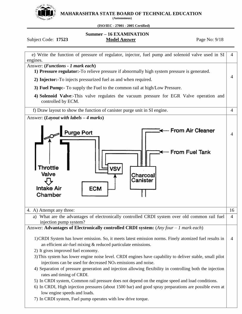
f) Draw layout to show the function of canister purge unit in SI engine. 4
Answer: (Layout with labels – 4 marks)
4
4. A) Attempt any three: 16
a) What are the advantages of electronically controlled CRDI system over old common rail fuel
injection pump system?
4
Answer: Advantages of Electronically controlled CRDI system: (Any four – 1 mark each)
1) CRDI System has lower emission. So, it meets latest emission norms. Finely atomized fuel results in
an efficient air-fuel mixing & reduced particulate emissions.
2) It gives improved fuel economy.
3) This system has lower engine noise level. CRDI engines have capability to deliver stable, small pilot
injections can be used for decreased NOx emissions and noise.
4) Separation of pressure generation and injection allowing flexibility in controlling both the injection
rates and timing of CRDI.
5) In CRDI system, Common rail pressure does not depend on the engine speed and load conditions.
6) In CRDI, High injection pressures (about 1500 bar) and good spray preparations are possible even at
low engine speeds and loads.
7) In CRDI system, Fuel pump operates with low drive torque.
4

MAHARASHTRA STATE BOARD OF TECHNICAL EDUCATION (Autonomous)
(ISO/IEC - 27001 - 2005 Certified)
Summer – 16 EXAMINATION
Subject Code: 17523 Model Answer Page No: 10/18
b) Draw block diagram of electronically controlled fuel injection system. 4
Answer: Block diagram of Electronically controlled fuel injection system:
OR
4

MAHARASHTRA STATE BOARD OF TECHNICAL EDUCATION (Autonomous)
(ISO/IEC - 27001 - 2005 Certified)
Summer – 16 EXAMINATION
Subject Code: 17523 Model Answer Page No: 11/18
c) What is glow plug? Describe its working in diesel engines. 4
Answer:
Glow Plug: Some diesel engines use an electric heater called glow plug inside the cylinders to heat the
intake air and help ignite fuel: air mixture. Glow plug is an aid for cold starting of a C.I. engine.
Modern glow plugs heat to required temp in just 4 seconds.
Working:-
The self-ignition temperature of diesel is 250°C. For compression ignition, the charge (air + diesel)
should reach a temperature of about 550°C. Cold weather conditions make it difficult to happen. So, a
glow plug is used in Compression Ignition Engines. The glow plug heats to starting temperature
(approx. 850°C) as rapidly as possible.
On modern vehicles, engine's central ECU controls- high electrical glow-plug current, indicator
lamp, Safety override and automatic switching off the Glow- plugs. An ignition starter lock controls the
current supply for the glow system. As the switch is actuated a relay connects the glow plug to the
battery circuit, and the Indicator lamp comes on. When the lamp goes out turning the switch further to
the starting position brings the engine to life. As long as the starter switch is held in the glow position, a
holding circuit assures that the glow- plugs remain on. Then after starting, when the ignition switch is
released, they are automatically switched off. A safety circuit prevents running the battery down if the
engine fails to start immediately. After a maximum of 90 seconds glow time, current to the glow plugs
is automatically interrupted. But starting may be attempted again as soon as the driver wishes.
Fig: ECU controlled Glow plug System on D.I. Engine
1
2
1

MAHARASHTRA STATE BOARD OF TECHNICAL EDUCATION (Autonomous)
(ISO/IEC - 27001 - 2005 Certified)
Summer – 16 EXAMINATION
Subject Code: 17523 Model Answer Page No: 12/18
d) Draw neat sketch of electronic fuel injector. 4
Answer: (sketch with labels - 4 marks)
4
B) Attempt any one: 6
a) Draw neat sketch to show EGR system and name it. 6
Answer: (Sketch -4 marks, Labels – 2 marks)
Figure: EGR SYSTEM
6
MAHARASHTRA STATE BOARD OF TECHNICAL EDUCATION (Autonomous)
(ISO/IEC - 27001 - 2005 Certified)
Summer – 16 EXAMINATION
Subject Code: 17523 Model Answer Page No: 13/18
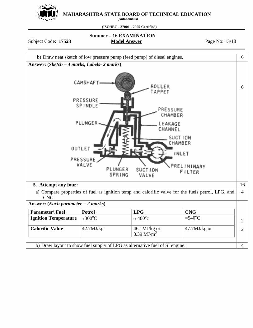
b) Draw neat sketch of low pressure pump (feed pump) of diesel engines. 6
Answer: (Sketch – 4 marks, Labels- 2 marks)
6
5. Attempt any four: 16
a) Compare properties of fuel as ignition temp and calorific valve for the fuels petrol, LPG, and
CNG.
4
Answer: (Each parameter = 2 marks)
Parameter\ Fuel Petrol LPG CNG
Ignition Temperature 300oC 400
oc =540
oC
Calorific Value 42.7MJ/kg 46.1MJ/kg or
3.39 MJ/m3
47.7MJ/kg or
2
2
b) Draw layout to show fuel supply of LPG as alternative fuel of SI engine. 4

MAHARASHTRA STATE BOARD OF TECHNICAL EDUCATION (Autonomous)
(ISO/IEC - 27001 - 2005 Certified)
Summer – 16 EXAMINATION
Subject Code: 17523 Model Answer Page No: 14/18
Answer: (Layout with labels – 4 marks, credit should be given to equivalent layouts) LPG Fuel Supply layout of S.I. engine.
4
c) What are the advantages of CNG fuel system? 4
Answer: (Four advantages – 1 mark each)
1. CNG is lead free and its use substantially reduces the harmful emission
2. Operating cost of the vehicle running on CNG is lower than that of petrol.
3. Reduced vehicle maintenance such as extended interval of oil change and standard spark plug last
longer, lower wear of engine parts. Life of lubricating oil is extended because CNG does not
contaminate and dilute the crank- case oil. The spark plug life is extended due to elimination of lead
fouling.
4. Fuel theft is not possible. Since NG cannot be siphoned off from a vehicle
5. CNG contains less carbon than any other fossil fuel and thus produces less CO2 / km.
6. CNG vehicle is as safe as petrol vehicle
7. The life cycle cost of a vehicle is lowest on CNG as compared to the other fuel – due to reduced
maintenance and less cost of CNG
8. CNG has a much higher Octane Number.—So, it is superior to petrol. And the anti- knock additives
are not required.
9. Being a gaseous fuel, CNG mixes with air easily and evenly.
10. Almost any petrol / diesel vehicle can be converted to operate on CNG.
11. As CNG is lead- free, vehicles with catalytic converters can also be fitted with CNG kit without
any difficulty.
12. Vehicles designed specifically to run on natural gas has no loss of power and may even have
greater power and efficiency. NG has Octane number 130 (For Petrol it is 87 to 96).
13. Soot production is virtually zero when this fuel is combusted in the diesel cycle.
14. NG is non corrosive implies increased component life.
4
MAHARASHTRA STATE BOARD OF TECHNICAL EDUCATION (Autonomous)
(ISO/IEC - 27001 - 2005 Certified)
Summer – 16 EXAMINATION
Subject Code: 17523 Model Answer Page No: 15/18
15. NG is non-toxic.
16. CNG is lighter than air and so Dissipates into atmosphere implies less chance of fire Hazard.
d) What are the limitations of LPG as alternative fuel? 4
Answer: Limitations of LPG as alternative fuel: (Four limitations – 1 mark each)
1. It reduces volumetric efficiency due to its high heat of vaporization.
2. Handling has to be done under pressure of about 18 bars.
3. It characteristic odour is faint. An odourant (usually Mercaptan) is usually added so that the people
will be aware of the leaks.
4. Much of its advantages can be realized (obtained) in engines of higher compression ratio.
5. Response to blending is very poor.
6. LPG produces 10 % less power for a given engine, at full throttle.
7. The vehicle weight is increased due to the use of heavy pressure cylinders for storing LPG
8. A special fuel feed system is required for LPG.
9. Reduced Boot space (Storage tank occupies part of the Boot space.)
10. Unlike petrol pumps, LPG filling stations are less in number. (Most of the stations are located in
cities). Therefore users inconvenience.
11. Operating range (Running Range) is less as compared to that of petrol
12. Starting problem with LPG
13. It is safe only if proper periodic maintenance of the gas system is done by trained person.
4
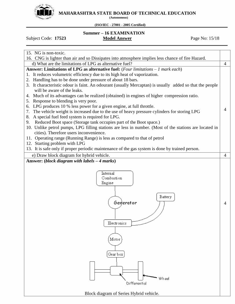
e) Draw block diagram for hybrid vehicle. 4
Answer: (block diagram with labels – 4 marks)
Block diagram of Series Hybrid vehicle.
4

MAHARASHTRA STATE BOARD OF TECHNICAL EDUCATION (Autonomous)
(ISO/IEC - 27001 - 2005 Certified)
Summer – 16 EXAMINATION
Subject Code: 17523 Model Answer Page No: 16/18
e) Write the working of an electric car. 4
Answer: (Working- 2 marks, block diagram/ sketch- 2 marks)
Working of an electric car:
The drive train of an Electric Vehicle consists of the power controller, the motor and transmission.
The power controller translates the position of the accelerator pedal into the appropriate motor current
and voltage. In most cases, the drive torque is a function of accelerator pedal position, as in case of
I.C. engines.
Onboard- charger rectifies AC to DC for charging batteries. Protection system has circuit breaker,
relays, fuses that are connected between the batteries and the rest of the electrical system and interrupt
the AC supply and / or isolate the batteries in case of fault. Motor is used to drive the Electric
Vehicle. Both AC and DC drives are used. Motor Controller controls the drive motor speed and
torque. Mechanical Drive Systems consists of the transmission, differential, power steering and other
non-electrical controls required for the motor drive.
Electric Vehicles use a microprocessor based controller that monitors the status of each of the
major components and initiates controls and protection actions as needed. The battery pack provides
energy for the vehicle propulsion.
Auxiliary power is supplied for the headlights, instrumentation, door opener, auxiliary motors
(eg for the sunroof), power steering etc.
Block diagram of Electric Car
2
2
6. Attempt any FOUR of the following: 16
a) What are the advantages of Variable Geometric Turbocharger (VGT) over old turbocharger? 4
Answer: Advantages of VGT over old turbocharger: (Any four - 1 mark each)
1. Reduced turbo- lag time.
2. Increased efficiency of engine/ lower fuel consumption.
3. Higher rated power output.
4. Enhanced low speed power.
5. Lower engine emissions.
4

MAHARASHTRA STATE BOARD OF TECHNICAL EDUCATION (Autonomous)
(ISO/IEC - 27001 - 2005 Certified)
Summer – 16 EXAMINATION
Subject Code: 17523 Model Answer Page No: 17/18
b) Compare Overhead Valve (OHV) mechanism and variable Value Timing (VVT) mechanism. 4
Answer: (four parameters = 1 mark each)
Parameter\ Mechanism Overhead Valve Mechanism
(OHV)
Variable Valve Timing
(VVT)
Engine performance Good Best performance
Fuel Economy Lower fuel economy Higher fuel economy
Exhaust emission Moderate exhaust emission Low exhaust emission
Torque Moderate torque Slightly increased torque
Design of mechanism Simple Complex design
Exhaust gas recirculation Needed to reduce NOx Not needed.
4
c) Why DTSI system is used in engines? 4
Answer: (Reason / Explanation – 4 marks, credit should be given to sketch, if drawn)
DTSI technology provides a combination of the light weight and twice the power offered by two-
stroke engines with a significant power boost, i.e. a considerably high "power-to-weight ratio"
compared to quite a few four-stroke engines. Moreover, such a system can adjust idling speed & even
cuts off fuel feed when the accelerator is released, and provides enrichment of the air-fuel mixture for
cold starting and acceleration; if necessary; it also prevents the upper rev. limit from being exceeded.
At higher speeds the over boost will enhance full power delivery and will stay on as long as the driver
exercises acceleration.
A microprocessor continuously senses engine speed and load, then it respond by altering the
ignition timing. It optimizes power and fuel economy.
Benefits of DTSI system over conventional Ignition system are as follows.
1. Optimized power.
2. Reduced emission level.
3. Less vibrations and noise.
4. Long life of the engine parts such as piston rings and valve stem.
5. Decrease in the specific fuel consumption. i.e. better fuel economy.
6. No overheating.
7. Increased Thermal Efficiency of the Engine & even withstands high load.
8. Better starting of engine even in winter season & cold climatic conditions or at very low
temperatures because of increased Compression ratio.
4

MAHARASHTRA STATE BOARD OF TECHNICAL EDUCATION (Autonomous)
(ISO/IEC - 27001 - 2005 Certified)
Summer – 16 EXAMINATION
Subject Code: 17523 Model Answer Page No: 18/18
d) List the methods / system used to improve fuel economy of SI engines. 4
Answer: Methods / system used to improve fuel economy of SI engines: (four points-1 mark each)
1) Use of multi-functional fuel additives will provide 3 to 4% fuel economy.
2) Good driving habits.
3) Properly maintained fuel supply system.
4) Use of computer controlled fuel injection system.
5) Use of computer controlled ignition system.
6) Use of higher voltage automotive electrical system (42 volts system)
4
e) List the pollutants of gasoline engines with their sources and reason. 4
Answer: (pollutant- source- reason= 1 mark each)
Pollutant\ Source\ Reason Source Reason
Carbon Monoxide (CO) Engine exhaust
crankcase emission
Incomplete combustion during idling
and deceleration
blowby
Carbon dioxide (CO2) Engine exhaust Combustion of air and fuel mixture
Oxides of Nitrogen Engine exhaust
High temperature of combustion
chamber (>1100°C, nitrogen reacts
with oxygen.)
Unburnt Hydrocarbon Carburettor, fuel tank
engine exhaust
Evaporation,
Incomplete combustion
4
f) What is meant by PCV and draw simple figure for it? 4
Answer: (Description- 2 marks, figure- 2 marks)
PCV – PCV means positive crankcase ventilation. It is a system that controls the emission from the
crankcase. It is used to keep the crankcase clean of blow-by gases. It prevents the contamination of
lubricating oil in the oil sump by fuel and products of combustion. It keeps the crankcase well
ventilated.
(Note: Credit should be given to Equivalent diagram)
2
2