Embed Size (px)
Citation preview

MAHARASHTRA STATE BOARD OF TECHNICAL EDUCATION (Autonomous)
(ISO/IEC - 27001 - 2005 Certified)
Model Solution : Summer 2016
----------------------------------------------------------------------------------------------------
Subject & Code: Engineering Mechanics (17204) Page No: 1 / 30
-------------------------------------------------------------------------------------------------------------------------
Important Instructions to examiners:
1) The answers should be examined by key words and not as word-to-word as given in the model answer
scheme.
2) The model answer and the answer written by candidate may vary but the examiner may try to assess the
understanding level of the candidate.
3) The language errors such as grammatical, spelling errors should not be given more importance. (Not
applicable for subject English and Communication Skills.)
4) While assessing figures, examiner may give credit for principal components indicated in the figure. The
figures drawn by the candidate and those in the model answer may vary. The examiner may give credit
for any equivalent figure drawn.
5) Credits may be given step wise for numerical problems. In some cases, the assumed constant values may
vary and there may be some difference in the candidate’s answers and the model answer.
6) In case of some questions credit may be given by judgment on part of examiner of relevant answer based
on candidate’s understanding.
7) For programming language papers, credit may be given to any other program based on
equivalent concept.
---------------------------------------------------------------------------------------------------------------------------------
Que.
No.
Sub.
Que. Model Answers Marks
Total
Marks
1
a)
Ans
b)
Ans
c)
Ans
Attempt any TEN of the following :
Define effort and effort lost in friction.
Effort(P): The force applied to lift the heavy loads is known as effort.
Effort lost in friction (Pf): It is the effort by considering the wear and
tear effect while use of machine.
OR
It is the effort obtained by subtracting ideal effort from an effort.
State any two uses of machines.
1) To lift heavy loads which is not possible manually.
2) To minimize the human beings efforts.
Draw nature of graph for load against Ideal effort.
Ideal
Effort
(Pi )
O
Load (W)
1 M
1 M
1M
each
2 M
20
2 M
2 M
2 M

MAHARASHTRA STATE BOARD OF TECHNICAL EDUCATION (Autonomous)
(ISO/IEC - 27001 - 2005 Certified)
Model Solution : Summer 2016
----------------------------------------------------------------------------------------------------
Subject & Code : Engineering Mechanics (17204) Page No: 2 / 30
Que.
No.
Sub.
Que. Model Answers Marks
Total
Marks
1
d)
Ans
e)
Ans
f)
Ans
g)
Ans
Define rigid body with one example.
Rigid Body: It is defined as the body which do not deform when
subjected to system of forces and it is fixed in position.
e. g. In fact, no body is perfectly rigid. Every body deforms slightly
under the action of forces. Hence, rigid body is a theoretical concept.
State any two effects of force on a body.
1) It may change the state of a body.
2) It may accelerate or retard the motion of a body.
3) It may turn or rotate the body on which it acts.
4) It may deform the body on which it acts.
Define coplanar parallel force system along with neat sketch.
Definition: If lines of action of forces are parallel to each other in the
same plane, the system is called as coplanar parallel force system.
Sketch :
Parallel forces may be like or unlike.
a) Like parallel forces: acting in same direction
P Q R S
b) Unlike parallel forces: acting in opposite direction
Q S
P R
What is polar diagram?
Polar Diagram : In case of non-concurrent or parallel force system the
point of application of resultant can be found out by constructing polar
diagram. Polar diagram is obtained from the vector diagram. To
construct a polar diagram, any point “O” known as pole is chosen near
the vector diagram and the points on the vector diagram are joined to
it. The lines joined in this way are known as rays.
1 M
1 M
1M
each
(any
two)
1 M
½ M
½ M
1 M
2 M
2 M
2 M
MAHARASHTRA STATE BOARD OF TECHNICAL EDUCATION (Autonomous)
(ISO/IEC - 27001 - 2005 Certified)
Model Solution : Summer 2016
----------------------------------------------------------------------------------------------------
Subject & Code : Engineering Mechanics (17204) Page No: 3 / 30
Que.
No.
Sub.
Que. Model Answers Marks
Total
Marks
1
h)
Ans
i)
Ans
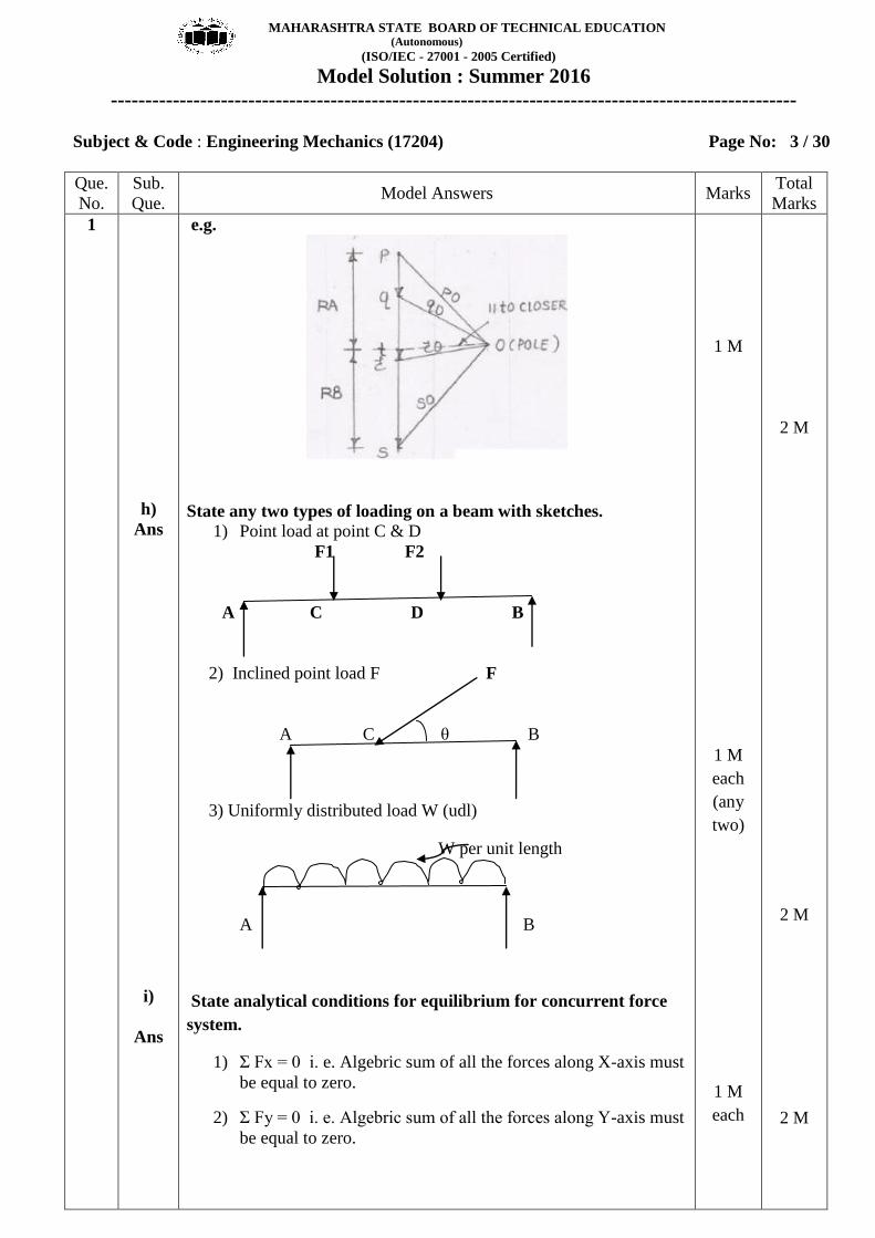
e.g.
State any two types of loading on a beam with sketches.
1) Point load at point C & D
F1 F2
A C D B
2) Inclined point load F F
A C θ B
3) Uniformly distributed load W (udl)
W per unit length
A B
State analytical conditions for equilibrium for concurrent force
system.
1) Σ Fx = 0 i. e. Algebric sum of all the forces along X-axis must
be equal to zero.
2) Σ Fy = 0 i. e. Algebric sum of all the forces along Y-axis must
be equal to zero.
1 M
1 M
each
(any
two)
1 M
each
2 M
2 M
2 M

MAHARASHTRA STATE BOARD OF TECHNICAL EDUCATION (Autonomous)
(ISO/IEC - 27001 - 2005 Certified)
Model Solution : Summer 2016
----------------------------------------------------------------------------------------------------
Subject & Code : Engineering Mechanics (17204) Page No: 4 / 30
Que.
No.
Sub.
Que. Model Answers Marks
Total
Marks
1
j)
Ans
k)
Ans
l)
Ans
State types of friction.
1) Static friction: The friction experienced by a body when it is in
equilibrium.
2) Dynamic friction: The friction experienced by a body when it is in
motion
3) Rolling : The friction experienced by a bodies when one rolls over
the another body.
4) Sliding: The friction experienced by a bodies when one slides over
the another body
Define cone of friction.
Cone of friction : The resultant reaction S makes an angle ϕ with
normal reaction R as shown for given set of axes XY.
Y-axis
S R S
ϕ ϕ
X –axis
If X axis is rotated about Y axis, the resultant reaction S will also
rotate. The line of action of action of S will always lie on surface of
right circular cone whose vertex angle is equal to 2ϕ. This cone is
known as cone of friction.
State velocity ratio for screw jack with meaning of term involved.
Velocity Ratio of Simple Screw jack is given by -
VR = 2πL / p --------- When handle of length L is provided
OR
VR = 2πR / p --------- When effort wheel is provided
Where, L = length of handle
P = pitch of screw
R = radius of an effort wheel.
1 M
each
( any
two)
1M for
dia-
gram
&
1 M
For
explan
ation
1 M
for
for-
mula
1 M
terms
used
2 M
2 M
2 M

MAHARASHTRA STATE BOARD OF TECHNICAL EDUCATION (Autonomous)
(ISO/IEC - 27001 - 2005 Certified)
Model Solution : Summer 2016
----------------------------------------------------------------------------------------------------
Subject & Code : Engineering Mechanics (17204) Page No: 5 / 30
Que.
No.
Sub.
Que. Model Answers Marks
Total
Marks
2
a)
Ans
b)
Ans
Answer any FOUR of the following :
In a certain machine effort was found to move a distance of 30 m,
when load moved through a distance of 1.5 m. If the machine is
ideal, find VR & MA of the machine.
Givens :
Distance moved by effort (y)= 30 m,
distance moved by load (x) = 1.5 m,
& the Machine is Ideal i. e. MA = VR
efficiency (η) = 100 %
Find:
M. A. & V. R. Of the machine
Solution:
(1) VR = y / x = 30 / 1.5 = 20
VR = 20
(2) Mechanical Advantage (M. A )
As machine is Ideal, i. e. its M. A. & V. R. both are same and its
efficiency (η) = 100 %
M. A. = V. R. = 20
For a general pulley block number of cogs on effort wheel is 24,
that of on load wheel is 6. Number of teeth on the pinion is 4 &
that of on spur is 36. If the maximum effort, which can be applied
is 60 N, calculate the maximum load that can be lifted, if efficiency
of machine is 80 %.
Given:
Geared pulley block machine
No of cogs on effort wheel (N1) = 24
No of cogs on load wheel (N4) = 6
No of cogs on pinion (N2) = 4
No of cogs on spur (N3) = 36,
Max effort(P) = 60 N,
(η) = 80 %
2 M
2 M
16 M
4 M

MAHARASHTRA STATE BOARD OF TECHNICAL EDUCATION (Autonomous)
(ISO/IEC - 27001 - 2005 Certified)
Model Solution : Summer 2016
----------------------------------------------------------------------------------------------------
Subject & Code : Engineering Mechanics (17204) Page No: 6 / 30
Que.
No.
Sub.
Que. Model Answers Marks
Total
Marks
2
c)
Ans
d)
Ans
Find: Max load lifted by machine(W)
Solution:
1)for given machine VR is given by
V. R. = N1 X N3 / N2X N4 = 24 x 36 / 4 x 6 = 36
VR = 36
2) Efficiency (η) = MA / VR X 100
80 = MA / 36 x 100
MA = 28.8
But, MA = W/P
28.8 = W/60
W = 1728 N
In a double purchase crab, the two pinions have 10 teeth each &
the two spur wheel has 60 teeth each. The diameter of load drum
is 20 cm & that of effort wheel is 60 cm. Find the velocity ratio.
Given:
Double purchase crab winch
No of teeths on spur (N1) & (N3) = 60
No of teeth on pinion (N2) & (N4) = 10
Diameter of load drum(D)= 20 cm &
effort wheel (d) = 60 cm
Find: Velocity Ratio(VR)
Solution:
For given machine VR is given by
V. R. = N1 X N3 X D / N2 X N4 X d
= 60x60x60 / 10x10x20
V. R. = 108
Resolve a force of 10 N magnitude passing through co-ordinates
(0,0) & (0,-2)
Given: Force 10 N passing through (0,0) & (0,-2)
Find: Resolution of force
(0,0)
(0,-2) 10 N
Fx = 10 cos 2700 = 0
Fy = 10 sin 2700 = -10 N
2 M
1 M
1 M
2 M
for
for-
mula
& 2 M
for
ans-
wer
1 M
1½ M
1½ M
4 M
4 M
4 M

MAHARASHTRA STATE BOARD OF TECHNICAL EDUCATION (Autonomous)
(ISO/IEC - 27001 - 2005 Certified)
Model Solution : Summer 2016
----------------------------------------------------------------------------------------------------
Subject & Code : Engineering Mechanics (17204) Page No: 7 / 30
Que.
No.
Sub.
Que. Model Answers Marks
Total
Marks
2
e)
Ans.
Determine the resultant of the forces acting on a hook as shown in
fig.
Given: Concurrent force system
Find: Resultant (R)
Solution:
Σ Fx = 20 cos 00 + 15 cos 60
0 + 30 cos 90
0 + 25 cos 30
0
= 5.849 N (+ve)
Σ Fy = 20 sin 00 + 15 sin 60
0 + 30 sin 90
0 + 25 sin 30
0
= 55.49 N (+ve)
Resultant (R)2 = Σ Fx
2 + Σ Fy
2 = 5.849
2 + 55.49
2
Hence, R = 55.797 N
Direction & Position of Resultant
As Σ Fx = + ve & Σ Fy = + ve, R lies in First Quadrant
1 1 55.49tan tan
5.849
83.98
Fy
Fx
1 M
1 M
1 M
1 M
4 M

MAHARASHTRA STATE BOARD OF TECHNICAL EDUCATION (Autonomous)
(ISO/IEC - 27001 - 2005 Certified)
Model Solution : Summer 2016
----------------------------------------------------------------------------------------------------
Subject & Code : Engineering Mechanics (17204) Page No: 8 / 30
Que.
No.
Sub.
Que. Model Answers Marks
Total
Marks
2
3
f)
Ans
a)
Ans.
A crank ABC with system of forces acting on it is shown in Fig.
Find force P to maintain equilibrium.
Given: 70 N force acting at 300 inclination as shown
Find: P, if equilibrium is maintained
P A Fy 70 N
300 mm Fx
300
B 250 mm
Taking moment @ point B & considering equilibrium condition
∑ M B = 0
= Fy x 250 – Px300 =70sin30 x 250 – 300P
P = 29.17 N
Attempt any FOUR of the following :
Find the angle between two forces of magnitude 120 N each, such
that their resultant is 60 N.
Givens :
P = Q = 120 N
R = 60 N
To find :
Ө
Solution :
Using Law of parallelogram of forces 2 2 2 2 cosR P Q PQ
2 2 2(60) (120) (120) 2 120 120cos
3600 14400 14400 28800cos
3600 28800 28800cos
3600 28800 28800cos
X X
2 M
2 M
1 M
1 M
4 M
16 M
MAHARASHTRA STATE BOARD OF TECHNICAL EDUCATION (Autonomous)
(ISO/IEC - 27001 - 2005 Certified)
Model Solution : Summer 2016
----------------------------------------------------------------------------------------------------
Subject & Code : Engineering Mechanics (17204) Page No: 9 / 30
Que.
No.
Sub.
Que. Model Answers Marks
Total
Marks
3
b)
Ans.
1
1
25200 28800cos
25200cos ( )
28800
cos ( 0.875)
151.04
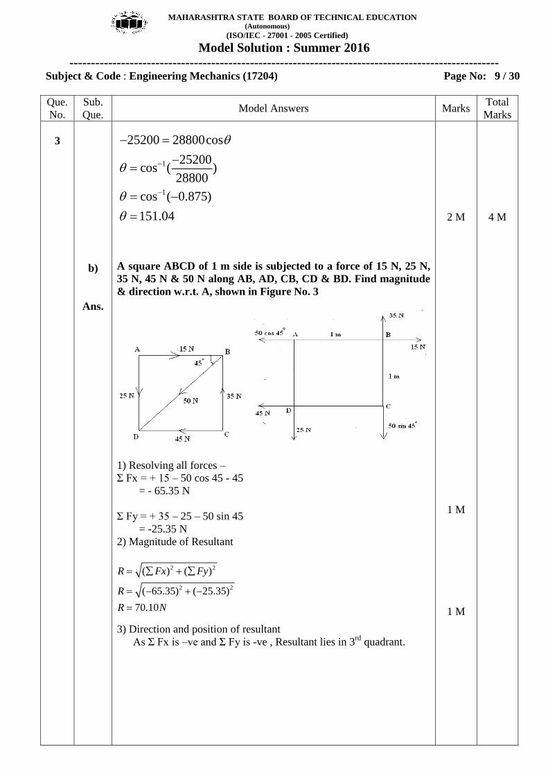
A square ABCD of 1 m side is subjected to a force of 15 N, 25 N,
35 N, 45 N & 50 N along AB, AD, CB, CD & BD. Find magnitude
& direction w.r.t. A, shown in Figure No. 3
1) Resolving all forces –
Σ Fx = + 15 – 50 cos 45 - 45
= - 65.35 N
Σ Fy = + 35 – 25 – 50 sin 45
= -25.35 N
2) Magnitude of Resultant
2 2
2 2
( ) ( )
( 65.35) ( 25.35)
70.10
R Fx Fy
R
R N
3) Direction and position of resultant
As Σ Fx is –ve and Σ Fy is -ve , Resultant lies in 3rd
quadrant.
2 M
1 M
1 M
4 M

MAHARASHTRA STATE BOARD OF TECHNICAL EDUCATION (Autonomous)
(ISO/IEC - 27001 - 2005 Certified)
Model Solution : Summer 2016
----------------------------------------------------------------------------------------------------
Subject & Code :Engineering Mechanics (17204) Page No: 10 / 30
Que.
No.
Sub.
Que. Model Answers Marks
Total
Marks
3
c)
Ans.
1 1 25.35tan tan
65.35
21.2
Fy
Fx
4) Position of Resultant w.r.to point A
Let x be the perpendicular distance of R from point A.
ΣMFA = (-35 X 1) + (50 sin 45 X 1) + (45 X 1) = + 45.35 Nm
MRA = + R. x = 70.10 x
Using Varignon’s theorem of moment
ΣMFA = MRA
45.35 = 70.10 x
x = 0.65 m
Hence, perpendicular distance of R from point A = 0.65 m
Find the resultant in magnitude & direction if following forces
acting away from a point.
( i) 300 N force acting 30 degree East of North
( ii) 150 N force acting 45 degree West of North
( iii) 200 N force towards West
( iv) 400 N force acting 30 degree West of South.
1 M
1 M
1 M
4 M

MAHARASHTRA STATE BOARD OF TECHNICAL EDUCATION (Autonomous)
(ISO/IEC - 27001 - 2005 Certified)
Model Solution : Summer 2016
----------------------------------------------------------------------------------------------------
Subject & Code: Engineering Mechanics (17204) Page No. 11 / 30
Que.
No.
Sub.
Que. Model Answers Marks
Total
Marks
3
d)
Ans.
1) Resolving all forces –
Σ Fx = + 300 cos 60 – 150 cos 45 – 200 – 400 cos 60
= + 150 – 106.066 – 200 - 200
= - 356.066 N
Σ Fy = + 300 sin 60 + 150 sin 45 – 400 sin 60
= + 259.807 + 106.066 – 346.410
= +19.463 N
2) Magnitude of Resultant
2 2
2 2
( ) ( )
( 356.066) (19.463)
356.597
R Fx Fy
R
R N
3) Direction and position of resultant
As Σ Fx is –ve and Σ Fy is +ve , Resultant lies in 2nd
quadrant.
1 1 19.463tan tan
356.597
3.128
Fy
Fx
Calculate resultant, direction & it’s position w.r.t. 400 N force for
given force system as shown in figure
1) Magnitude of Resultant
R = - 400 – 600 – 200 + 800 = - 400 N ( ) - ve sign indicates Resultant acts vertically downwards.
½ M
½ M
1 M
1 M
1 M
4 M

MAHARASHTRA STATE BOARD OF TECHNICAL EDUCATION (Autonomous)
(ISO/IEC - 27001 - 2005 Certified)
Model Solution : Summer 2016
----------------------------------------------------------------------------------------------------
Subject & Code: Engineering Mechanics (17204) Page No. 12 / 30
Que.
No.
Sub.
Que. Model Answers Marks
Total
Marks
3
e)
Ans.
f)
Ans.
2) Position of Resultant
Considering Varignon’s theorem of moment & taking moment of all
forces @ about 400 N force.
Let, R acts at x distance from 400 N force.
Σ MF = MR
(400 X 0) + (600 X 2) + (200 X 6) – (800 X 9) = - R X x
- 4800 = - 400 X x
x = 12 m
Hence, R must be located at 12 m distance from 400 N force, so as to
produce anti - clockwise moment.
Explain the following :
( i) Resolution of a force
(ii) Composition of force
( i) Resolution of a force - The way of representing a single force into
number of forces without changing the effect of the force on the body
is called as resolution of force.
(ii) Composition of force – The process of finding out the resultant
force of a given system of forces is called as composition of forces.
Solve Que. 3 (d) by graphical method.
1 M
2 M
2 M
2 M
4 M
4 M

MAHARASHTRA STATE BOARD OF TECHNICAL EDUCATION (Autonomous)
(ISO/IEC - 27001 - 2005 Certified)
Model Solution : Summer 2016
----------------------------------------------------------------------------------------------------
Subject & Code: Engineering Mechanics (17204) Page No. 13 / 30
Que.
No.
Sub.
Que. Model Answers Marks
Total
Marks
3
2 M
with
labe-
lling
&
positio
n of R
2 M
with
labe-
lling
&
magni-
tude of
R
4 M

MAHARASHTRA STATE BOARD OF TECHNICAL EDUCATION (Autonomous)
(ISO/IEC - 27001 - 2005 Certified)
Model Solution : Summer 2016
----------------------------------------------------------------------------------------------------
Subject & Code: Engineering Mechanics (17204) Page No. 14 / 30
Que.
No.
Sub.
Que. Model Answers Marks
Total
Marks
4
a)
Ans.
Attempt any Four of the following :
Two men carry a weight 200 N by means of ropes fixed to the
weight. One rope is inclined at 45 degree & other 30 degree with
the vertical. Find tension in each side of rope.
Using Lami’s theorem,
1 2
1 2
sin 75 sin150 sin135
200
sin 75 sin150 sin135
W T T
T T
(1) (2) (3)
Using term (1) and (2)
1200
sin75 sin150
T
1
sin150200
sin75T X
T1 = 103.527 N
Using term (1) and (3)
2200
sin75 sin135
T
2
sin135200
sin75T X
T2 = 146.410 N
1 M
1 M
1 M
1 M
16
4 M

MAHARASHTRA STATE BOARD OF TECHNICAL EDUCATION (Autonomous)
(ISO/IEC - 27001 - 2005 Certified)
Model Solution : Summer 2016
----------------------------------------------------------------------------------------------------
Subject & Code: Engineering Mechanics (17204) Page No. 15 / 30
Que.
No.
Sub.
Que. Model Answers Marks
Total
Marks
4
b)
Ans.
c)
Ans.
If four forces acting at a point (all away from the point) are 100
N, 200 N, T & P at 0°, 120°, 240° & 330°. Determine the value of T
& P, if the system is in equilibrium.
1) For equilibrium of a body,
Σ Fx = 0 & Σ Fy = 0
Resolving all forces –
Σ Fx = + 100 – 200 cos 60 – T cos 60 + P cos 30 = 0
0 = - (0.5 ) T + (0.866) P
0 = (0.5) T – (0.866) P --------------------(1)
Σ Fy = + 200 sin 60 – T sin 60 – P sin 30 = 0
0 = 173.205 – (0.866) T – (0.5 ) P
173.205 = (0.866) T + (0.5) P --------------------(2)
Solving Eqn. (1) & (2) simultaneously,
T = 150 N
P = 86.605 N
State Lami’s theorem & give its limitations.
Lami’s theorem – It states that, if three forces acting at a point on a
body keep it at rest, then each force is proportional to the sine of the
angle between the other two forces.
1 M
1 M
1 M
1 M
1 M
4 M

MAHARASHTRA STATE BOARD OF TECHNICAL EDUCATION (Autonomous)
(ISO/IEC - 27001 - 2005 Certified)
Model Solution : Summer 2016
----------------------------------------------------------------------------------------------------
Subject & Code: Engineering Mechanics (17204) Page No. 16 / 30
Que.
No.
Sub.
Que. Model Answers Marks
Total
Marks
4
d)
Ans.
As per Lami’s theorem,
1 2 3
sin
F F F
sin sin
Limitations of Lami’s theorem –
(1) It is applicable only when body is in equilibrium.
(2) It is applicable only for concurrent force system.
(3) It is applicable only when there are three forces only.
(4) It is applicable only when three forces are acting away from
the point.
A beam of span 4 m is simply supported at it’s end. It carries a
concentrated loads of 40 KN & 20 KN at 1 m & 2 m from left
hand support respectively. It carries udl of 10 kN/m for 2 m from
the right end. Determine the reactions at support.
1) Equivalent point load and it’s position
Equivalent point load = Intensity of udl X span of udl
= 10 X 2
= 20 KN
Position from RA = 2 m + Span of udl / 2 = 2 + (2/2) = 3 m
1 M
1 M
each
(any
two)
1 M
4 M

MAHARASHTRA STATE BOARD OF TECHNICAL EDUCATION (Autonomous)
(ISO/IEC - 27001 - 2005 Certified)
Model Solution : Summer 2016
----------------------------------------------------------------------------------------------------
Subject & Code: Engineering Mechanics (17204) Page No. 17 / 30
Que.
No.
Sub.
Que. Model Answers Marks
Total
Marks
4
e)
Ans.
2) Applying equilibrium conditions
Σ Fy = 0 and Σ M = 0
Σ Fy = 0
RA – 40 – 20 - 20 + RB = 0
RA + RB = 80 KN -------(1)
Σ MA = 0
Taking moment of all forces @ point A
(RA x 0) + (40 X 1) + (20 X 2) + (20 X 3) – (RB X 4) = 0
RB = 35 KN
Putting value of RB in eqn. (1)
RA + 35 = 80
RA = 45 KN
Solve Que. 4 (d) by graphical method.
1 M
1 M
1 M
2 M
with
labe-
lling
2 M
with
labe-
lling
&
magni-
tude of
of RA
& RB
4 M
4 M
MAHARASHTRA STATE BOARD OF TECHNICAL EDUCATION (Autonomous)
(ISO/IEC - 27001 - 2005 Certified)
Model Solution : Summer 2016
----------------------------------------------------------------------------------------------------
Subject & Code: Engineering Mechanics (17204) Page No. 18 / 30
Que.
No.
Sub.
Que. Model Answers Marks
Total
Marks
4
f)
Ans.
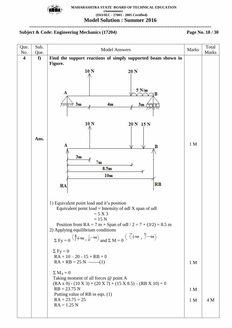
Find the support reactions of simply supported beam shown in
Figure.
1) Equivalent point load and it’s position
Equivalent point load = Intensity of udl X span of udl
= 5 X 3
= 15 N
Position from RA = 7 m + Span of udl / 2 = 7 + (3/2) = 8.5 m
2) Applying equilibrium conditions
Σ Fy = 0 and Σ M = 0
Σ Fy = 0
RA + 10 – 20 - 15 + RB = 0
RA + RB = 25 N -------(1)
Σ MA = 0
Taking moment of all forces @ point A
(RA x 0) - (10 X 3) + (20 X 7) + (15 X 8.5) – (RB X 10) = 0
RB = 23.75 N
Putting value of RB in eqn. (1)
RA + 23.75 = 25
RA = 1.25 N
1 M
1 M
1 M
1 M
4 M
MAHARASHTRA STATE BOARD OF TECHNICAL EDUCATION (Autonomous)
(ISO/IEC - 27001 - 2005 Certified)
Model Solution : Summer 2016
----------------------------------------------------------------------------------------------------
Subject & Code: Engineering Mechanics (17204) Page No. 19 / 30
Que.
No.
Sub.
Que. Model Answers Marks
Total
Marks
5
a)
Ans.
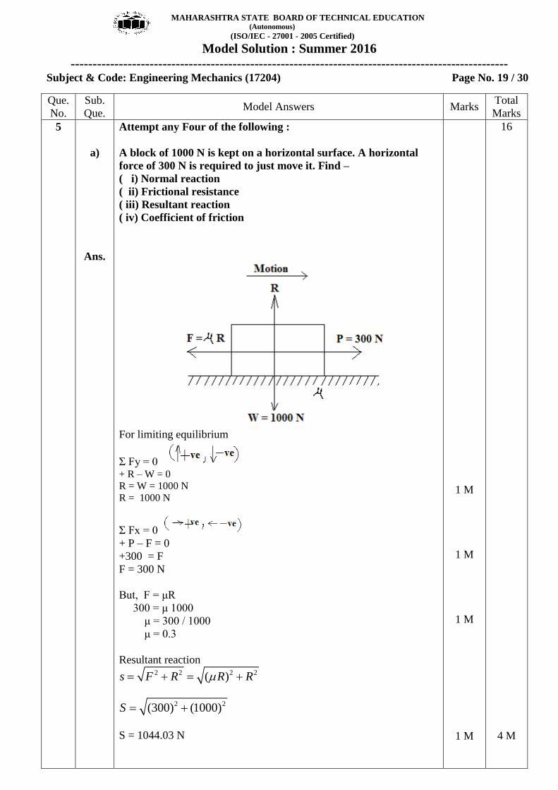
Attempt any Four of the following :
A block of 1000 N is kept on a horizontal surface. A horizontal
force of 300 N is required to just move it. Find –
( i) Normal reaction
( ii) Frictional resistance
( iii) Resultant reaction
( iv) Coefficient of friction
For limiting equilibrium
Σ Fy = 0 + R – W = 0
R = W = 1000 N
R = 1000 N
Σ Fx = 0
+ P – F = 0
+300 = F
F = 300 N
But, F = μR
300 = μ 1000
μ = 300 / 1000
μ = 0.3
Resultant reaction 2 2 2 2( )s F R R R
2 2(300) (1000)S
S = 1044.03 N
1 M
1 M
1 M
1 M
16
4 M

MAHARASHTRA STATE BOARD OF TECHNICAL EDUCATION (Autonomous)
(ISO/IEC - 27001 - 2005 Certified)
Model Solution : Summer 2016
----------------------------------------------------------------------------------------------------
Subject & Code: Engineering Mechanics (17204) Page No. 20 / 30
Que.
No.
Sub.
Que. Model Answers Marks
Total
Marks
5
b)
Ans.
c)
Ans.
Find the value of μ if the body is in limiting equilibrium. Refer
fig.
For limiting equilibrium
Σ Fy = 0 + R – W – 400 sin 30= 0
R = 1000 + 200
R = 1200 N
Σ Fx = 0 + 400 cos 30 – F = 0
F = 346.410 N
But, F = μR
346.410 = μ (1200)
μ = 346.410 / 1200
μ = 0.288
A block weighing 300 N is resting on an inclined plane making an
angle of 30° with the horizontal. Calculate the pull applied
parallel to the plane to move the block up the plane if μ = 0.35.
1 M
1 M
2 M
2 M
4 M

MAHARASHTRA STATE BOARD OF TECHNICAL EDUCATION (Autonomous)
(ISO/IEC - 27001 - 2005 Certified)
Model Solution : Summer 2016
----------------------------------------------------------------------------------------------------
Subject & Code: Engineering Mechanics (17204) Page No. 21 / 30
Que.
No.
Sub.
Que. Model Answers Marks
Total
Marks
5
d)
Ans.
Consider inclined plane as x-x axis and perpendicular to it as y-y axis.
For limiting equilibrium
Σ Fy = 0 + R – W cos 30 = 0
R = 300 cos 30
R = 259.807 N
Σ Fx = 0
+P - F – W sin 30 = 0
+P = (0.35 X 259.807) + 300 sin 30
P = 240.93 N
Draw FBD of a ladder resting against a wall & floor having
weight W.
Where,
μg = Coefficient of friction between the ladder & the ground
μw = Coefficient of friction between the ladder & the wall
Rg = Normal reaction at the ground
Rw = Normal reaction at the wall
Fg = Frictional force between the ladder & the ground
Fw = Frictional force between the ladder & the wall
1 M
1 M
2 M
Fig.
+ 1 M
forces
1 M
4 M
4 M

MAHARASHTRA STATE BOARD OF TECHNICAL EDUCATION (Autonomous)
(ISO/IEC - 27001 - 2005 Certified)
Model Solution : Summer 2016
----------------------------------------------------------------------------------------------------
Subject & Code: Engineering Mechanics (17204) Page No. 22 / 30
Que.
No.
Sub.
Que. Model Answers Marks
Total
Marks
5
e)
Ans.
f)
Ans.
Following observations were made in a end of simple lifting
machine with VR = 100.
Load Effort
5 KN 150 KN
10 KN 200 KN
Determine law of machine & Max. efficiency of machine.
1) Law of machine is given by P = (mW + C) KN
Putting values of W & P from above table –
150 = m (5) + C ---------- (1)
200 = m (10) + C ---------- (2)
Subtracting Eqn. (2) from (1)
150 = m (5) + C
_200 = _m (10) + C
________________
-50 = - m (5)
Hence, m = 50 / 5 = 10
Putting value of m in Eqn (1)
150 = (10 X 5) + C
C = 100 KN
Law of machine is -
P = (10 W + 100) KN
MAmax = 1/m = 1 / 10 = 0.1
maxmax
max
max
. .% 100
. .
0.1% 100
100
% 0.1%
M AX
V R
X
In a differential wheel & axle, the diameter of wheel is 36 cm &
that of axles are 9 cm & 6 cm. If the efficiency of the machine is
80 %, find the load lifted with an effort of 100 N.
(1) VR of differential axle & wheel is given by -
1 2
2 2 36
9 6
24
D XVR
d d
VR
1 M
1 M
1 M
1 M
2 M
4 M

MAHARASHTRA STATE BOARD OF TECHNICAL EDUCATION (Autonomous)
(ISO/IEC - 27001 - 2005 Certified)
Model Solution : Summer 2016
----------------------------------------------------------------------------------------------------
Subject & Code: Engineering Mechanics (17204) Page No. 23 / 30
Que.
No.
Sub.
Que. Model Answers Marks
Total
Marks
5
6
a)
Ans.
. .% 100
. .
80 10024
80 2419.2
100
M AX
V R
MAX
XMA
19.2100
19.2 100
1920
WMA
P
W
W X
W N
Attempt any Four of the following :
Locate the centroid of T section 100 X 100 X 10 mm having total
depth of 100 mm.
1) Figure is symmetric @ y-y axis and hence,
x‾ = Maximum horizontal dimension /2
= 100 / 2
= 50 mm
1 M
1 M
1 M
1 M
4 M
16

MAHARASHTRA STATE BOARD OF TECHNICAL EDUCATION (Autonomous)
(ISO/IEC - 27001 - 2005 Certified)
Model Solution : Summer 2016
----------------------------------------------------------------------------------------------------
Subject & Code: Engineering Mechanics (17204) Page No. 24 / 30
Que.
No.
Sub.
Que. Model Answers Marks
Total
Marks
6
b)
Ans.
2) Area calculation
A1 = 90 X 10 = 900 mm2
A2 = 100 X 10 = 1000 mm2
A = A1 + A2 = 1900 mm2
3) Location of y‾
y1 = 90 / 2 = 45 mm
y2 = 90 + (10/2) = 95 mm
1 1 2 2
(900 45) (1000 95)
1900
71.315
A y A yy
A
X Xy
y mm
Hence, centroid (G) for given section lies at G(,x y
)
= ( 50 mm from OB and 71.315 mm from OA)
Locate the centroid of the shaded area as shown in figure.
1) Let, Fig. 1 – Quarter circle and Fig. 2 – Semi Circle
Area Calculation
2 221
1
2 222
2
2
1 2
(1)0.7854
4 4
(0.5)0.3927
2 2
0.3927
rA m
rA m
A A A m
1 M
1 M
1 M
4 M

MAHARASHTRA STATE BOARD OF TECHNICAL EDUCATION (Autonomous)
(ISO/IEC - 27001 - 2005 Certified)
Model Solution : Summer 2016
----------------------------------------------------------------------------------------------------
Subject & Code: Engineering Mechanics (17204) Page No. 25 / 30
Que.
No.
Sub.
Que. Model Answers Marks
Total
Marks
6
c)
Ans.
2) x calculation
11
22
1 1 2 2
4 4 10.424
3 3
4 4 0.50.212
3 3
(0.7854 0.424) (0.3927 0.212)
0.3927
0.64
r Xx m
r Xx m
A x A x X Xx
A
x m
3) y calculation
11
2 2
1 1 2 2
4 4 10.424
3 3
0.5
(0.7854 0.424) (0.3927 0.5)
0.3927
0.35
r Xy m
y r m
A y A y X Xy
A
y m
Hence, centroid (G) for given section lies at G( ,x y)
= ( 0.64 m from OB and 0.35 m from OA)
Define centroid. Show on sketch the C. G. of a semicircle of
diameter 200 mm.
Centroid :- It is defined as the point through which the entire area of
a plane figure is assumed to act, for all positions of the lamina.
e. g. Triangle, Square
C. G. of a semicircle
100
4 4 10042.44
3 3
x r mm
r Xy mm
1½ M
1½ M
2 M
2 M
4 M
4 M

MAHARASHTRA STATE BOARD OF TECHNICAL EDUCATION (Autonomous)
(ISO/IEC - 27001 - 2005 Certified)
Model Solution : Summer 2016
----------------------------------------------------------------------------------------------------
Subject & Code: Engineering Mechanics (17204) Page No. 26 / 30
Que.
No.
Sub.
Que. Model Answers Marks
Total
Marks
6
d)
Ans.
Locate the position of centroid of an ice – cream cone as shown in
figure
NOTE : Considering Centroid
1) Figure is symmetric @ y-y axis and hence,
x‾ = Maximum horizontal dimension /2
= 200 / 2
= 100 mm
2) Area Calculation
2
1 1
2 22
2
2
1 2
1 1200 600 60000
2 2
(100)15707.96
2 2
75707.96
A bh X X mm
rA mm
A A A mm
3) y calculation
1 1
2 1
2 2600 400
3 3
4 4 100600 642.44
3 3
y h X mm
r Xy h mm
1 M
1 M
1 M

MAHARASHTRA STATE BOARD OF TECHNICAL EDUCATION (Autonomous)
(ISO/IEC - 27001 - 2005 Certified)
Model Solution : Summer 2016
----------------------------------------------------------------------------------------------------
Subject & Code: Engineering Mechanics (17204) Page No. 27 / 30
Que.
No.
Sub.
Que. Model Answers Marks
Total
Marks
6
Ans.
1 1 2 2
450.30
A y A yy
A
y mm
Hence, centroid (G) for given ice cream cone lies at G( ,x y)
= ( 100 mm from OB and 450.30 mm from OA)
OR
NOTE : Considering Center of Gravity of ice-cream
cone.
1) Figure is symmetric @ y-y axis and hence,
x‾ = Maximum horizontal dimension /2
= 200 / 2
= 100 mm
2) Volume Calculation
2 2 6 3
1 1 1
3 3 6 3
2 2
6 3
1 2
(1/3) (1/3) (100) 600 6.28318 10
(2/3) (2 /3) (100) 2.094395 10
8.377575 10
V r h X X mm
V r X mm
V V V X mm
3) y calculation
11 1
22 1
1 1 2 2
600600 450
4 4
3 3 100600 637.5
8 8
496.875
hy h mm
r Xy h mm
V y V yy
V
y mm
Hence, Centre of Gravity (G) for given ice cream cone lies at G( ,x y)
= ( 100 mm from OB and 496.875 mm from OA)
1 M
1 M
1 M
1 M
1 M
4 M
4 M

MAHARASHTRA STATE BOARD OF TECHNICAL EDUCATION (Autonomous)
(ISO/IEC - 27001 - 2005 Certified)
Model Solution : Summer 2016
----------------------------------------------------------------------------------------------------
Subject & Code: Engineering Mechanics (17204) Page No. 28 / 30
Que.
No.
Sub.
Que. Model Answers Marks
Total
Marks
6 e)
Ans.
Find the y- of the composite body given in figure.
1) Figure is symmetric @ y-y axis and hence,
x‾ = Maximum horizontal dimension /2
= 6 / 2
= 3 cm
2) Volume Calculation
2 2 3
1 1 1
2 2 3
2 2 2
3
1 2
(1) 6 18.849
(3) 2 56.548
75.397
V r h X cm
V r h X cm
V V V cm
1 M

MAHARASHTRA STATE BOARD OF TECHNICAL EDUCATION (Autonomous)
(ISO/IEC - 27001 - 2005 Certified)
Model Solution : Summer 2016
----------------------------------------------------------------------------------------------------
Subject & Code: Engineering Mechanics (17204) Page No.29 / 30
Que.
No.
Sub.
Que. Model Answers Marks
Total
Marks
6
f)
Ans.
3) y calculation
11
22 1
1 1 2 2
63
2 2
26 7
2 2
6
hy cm
hy h cm
V y V yy
V
y cm
Hence, centre of gravity (G) for given composite body lies at G( ,x y)
= ( 3 cm from OB and 6 cm from OA)
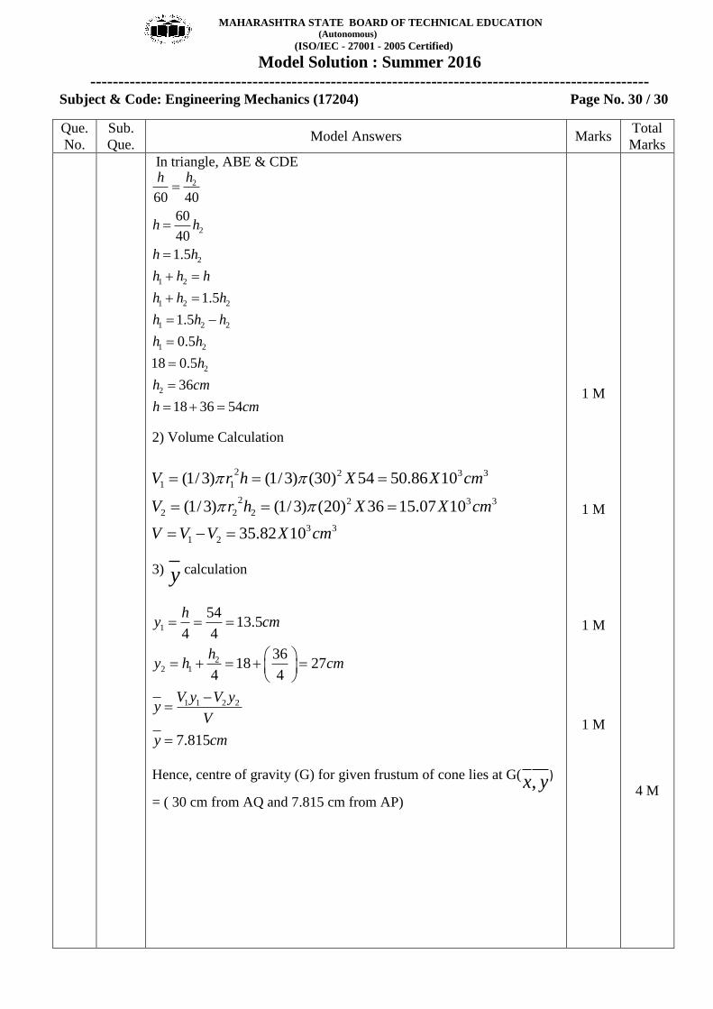
The frustum of a cone has top diameter 40 cm & bottom diameter
60 cm with height 18 cm. Calculate y only.
Let, Full cone as Fig. 1 & cut cone as Fig. 2
1) Figure is symmetric @ y-y axis and hence,
x‾ = Maximum horizontal dimension /2
= 60 / 2
= 30 cm
h1 = 18 cm, h2 = Height of cut cone
1 M
1 M
1 M
4 M
MAHARASHTRA STATE BOARD OF TECHNICAL EDUCATION (Autonomous)
(ISO/IEC - 27001 - 2005 Certified)
Model Solution : Summer 2016
----------------------------------------------------------------------------------------------------
Subject & Code: Engineering Mechanics (17204) Page No. 30 / 30
Que.
No.
Sub.
Que. Model Answers Marks
Total
Marks
In triangle, ABE & CDE
2
2
2
1 2
1 2 2
1 2 2
1 2
2
2
60 40
60
40
1.5
1.5
1.5
0.5
18 0.5
36
18 36 54
h h
h h
h h
h h h
h h h
h h h
h h
h
h cm
h cm
2) Volume Calculation
2 2 3 3
1 1
2 2 3 3
2 2 2
3 3
1 2
(1/3) (1/3) (30) 54 50.86 10
(1/3) (1/3) (20) 36 15.07 10
35.82 10
V r h X X cm
V r h X X cm
V V V X cm
3) y calculation
1
22 1
1 1 2 2
5413.5
4 4
3618 27
4 4
7.815
hy cm
hy h cm
V y V yy
V
y cm
Hence, centre of gravity (G) for given frustum of cone lies at G( ,x y)
= ( 30 cm from AQ and 7.815 cm from AP)
1 M
1 M
1 M
1 M
4 M


![MAHARASHTRA STATE BOARD OF TECHNICAL EDUCATION (Autonomous) · MAHARASHTRA STATE BOARD OF TECHNICAL EDUCATION (Autonomous) ... (Power) Forging: [1] Hand hammer blows impact will not](https://img.pdfslide.net/doc/110x75/5e6e089dafa70a54a11426bc/maharashtra-state-board-of-technical-education-autonomous-maharashtra-state-board.jpg)