Embed Size (px)
Citation preview

MAHARASHTRA STATE BOARD OF TECHNICAL EDUCATION (Autonomous)
(ISO/IEC - 27001 - 2005 Certified)
__________________________________________________________________________________________________
WINTER– 14 EXAMINATION
Subject Code: 17412 (TOM) Model Answer
Important Instructions to examiners:
1) The answers should be examined by key words and not as word-to-word as given in the
model answer scheme.
2) The model answer and the answer written by candidate may vary but the examiner may try
to assess the understanding level of the candidate.
3) The language errors such as grammatical, spelling errors should not be given more
Importance (Not applicable for subject English and Communication Skills.
4) While assessing figures, examiner may give credit for principal components indicated in the
figure. The figures drawn by candidate and model answer may vary. The examiner may give credit for any
equivalent figure drawn.
5) Credits may be given step wise for numerical problems. In some cases, the assumed constant
values may vary and there may be some difference in the candidate’s answers and model answer.
6) In case of some questions credit may be given by judgement on part of examiner of relevant answer based on
candidate’s understanding.
7) For programming language papers, credit may be given to any other program based on equivalent concept.
Q 1 A) Any SIX (02 Marks each )
a) i) Spherical pair: When the two elements of a pair are connected in such a way that one element (with
spherical shape) turns or swivels about the other fixed element, the pair formed is called a spherical pair. The ball and
socket joint, attachment of a car mirror, pen stand etc., are the examples of a spherical pair.
ii) Higher Pair : When two kinematic links are joined together so that they have point or line contact between
them, they are said to form Higher pair. e.g. Ball bearing
b) i) Radial follower: If the axis of follower and center of rotation of cam lie on a same straight line, it is known as
Radial follower.
ii) Offset follower: If the axis of follower and center of rotation of cam have some distance (offset) between
them, it is known as offset follower.
c) Crowning of Pulley: To avoid the slipping of the belt from the flat pulleys, two sides of pulleys are tapered. This
kind of tapering is known as crowning of pulleys.
d) Initial tension : When a belt is wound round the two pulleys (i.e. driver and follower), its two ends are joined
together ; so that the belt may continuously move over the pulleys, since the motion of the belt from the driver and
the follower is governed by a firm grip, due to friction between the belt and the pulleys.

MAHARASHTRA STATE BOARD OF TECHNICAL EDUCATION (Autonomous)
(ISO/IEC - 27001 - 2005 Certified)
__________________________________________________________________________________________________
Effects: In order to increase this grip, the belt is tightened up. At this stage, even when the pulleys are stationary, the
belt is subjected to some tension, called initial tension. When the driver starts rotating, it pulls the belt from one side
(increasing tension in the belt on this side) and delivers it to the other side (decreasing the tension in the belt on that
side). The increased tension in one side of the belt is called tension in tight side and the decreased tension in the
other side of the belt is called tension in the slack side.
e) Fluctuation of speed : The variations of energy above and below the mean speed value are called fluctuations of
speed. It is abbreviated as CS
Fluctuation of energy : The variations of energy above and below the mean resisting torque line are called
fluctuations of energy. It is abbreviated as CE.
f) Sensitivity: The sensitiveness is defined as the ratio of the difference between the maximum and
minimum equilibrium speeds to the mean equilibrium speed. It is an indicator of variation in speeds at different loads
conditions. It is considered that for a small change in load there should be minimum change in the configuration of
governor.
g) Internal expanding brakes:
h) Adverse effect of imbalance in rotating elements: i) Vibrations are caused ii) Machine accuracy gets disturbed iii)
Life of machine decreases iv) Friction increases v) Noise level increases
Q 1 B) Any two
a) Inversions of single slider crank chain: (01 mark)
i) Oscillating cylinder mechanism
ii) Pendulum pump
iii) Rotary engine
iv) Whitworth’s quick return mechanism
Oscillating cylinder engine
( 01 mark for figure, 02 marks explanation)
The arrangement of oscillating cylinder engine mechanism, as
shown in Fig. is used to convert reciprocating motion into rotary
motion. In this mechanism, the link 3 forming the turning pair is
fixed. The link 3 corresponds to the connecting rod of a
reciprocating steam engine mechanism. When the crank (link 2) rotates, the piston attached to piston rod (link 1)
reciprocates and the cylinder (link 4) oscillates about a pin pivoted to the fixed link at A.

MAHARASHTRA STATE BOARD OF TECHNICAL EDUCATION (Autonomous)
(ISO/IEC - 27001 - 2005 Certified)
__________________________________________________________________________________________________
Q 1 B) b) Four types of friction clutches: ( 01 mark each)
Single Disc or plate clutch: Heavy motor vehicles like trucks and buses
Multi plate clutch: Motor bikes / motorcycles
Cone clutches : Earlier it was used in automobiles but now used in special machines only
Centrifugal clutches: Mopeds
Q 1 B) c) Slip: ( 02 marks)
Due to increasing load that can cause some forward motion of the belt without carrying the driven pulley with
it, this is called slip of the belt and is generally expressed as a percentage.
The result of the belt slipping is to reduce the velocity ratio of the system.
Creep: ( 02 marks)
When the belt passes from the slack side to the tight side, a certain portion of the belt extends and it contracts
again when the belt passes from the tight side to slack side. Due to these changes of length, there is a relative motion
between the belt and the pulley surfaces. This relative motion is termed as creep.
The total effect of creep is to reduce slightly the speed of the driven pulley or follower.
Q 2 : Any FOUR
a) Machine: ( 01 mark for definition , 03 marks for difference)
It is defined as combination of number of links having relative motion between them so as to do some useful
work by consuming some energy as input.
Difference Between a Machine and a Structure
The following differences between a machine and a structure :
� The parts of a machine move relative to one another, whereas the members of a structure do not move
relative to one another.
� A machine transforms the available energy into some useful work, whereas in a structure no energy is
transformed into useful work.
� The links of a machine may transmit both power and motion, while the members of a structure transmit
forces only.
Q 2 b) Scotch Yoke mechanism: (figure 02 marks, explanation 02 marks)
This mechanism is used for converting rotary motion into a reciprocating
motion. The inversion is obtained by fixing either the link 1 or link 3. In Fig.
link 1 is fixed. In this mechanism, when the link 2 (which corresponds to
crank) rotates about B as centre, the link 4 (which corresponds to a frame)
reciprocates. The fixed link 1 guides the frame.

MAHARASHTRA STATE BOARD OF TECHNICAL EDUCATION (Autonomous)
(ISO/IEC - 27001 - 2005 Certified)
__________________________________________________________________________________________________
Q 2 c) Relation between Linear and Angular velocity ( 02 marks)
Consider link OA of any mechanism.
Let V as linear velocity of a point A w.r.t. O , say, in cm/sec
ω as angular velocity of a link OA, in Rad/sec
r as length of a link OA in cm
Then,
VAO = r x ω
Relation between Linear and Angular acceleration ( 02 marks)
Let f as linear acceleration of a point A w.r.t. O , say, in cm/sec2
α as angular acceleration of a link OA, in Rad/sec2
Then,
fAO = r x ω2
or V2
AO / r
αOA = ftAO / r rad /sec
2
where ftAO is the tangential component of acceleration of point A w.r.t. O
Q 2 d) Klein’s Construction
MAHARASHTRA STATE BOARD OF TECHNICAL EDUCATION (Autonomous)
(ISO/IEC - 27001 - 2005 Certified)
__________________________________________________________________________________________________
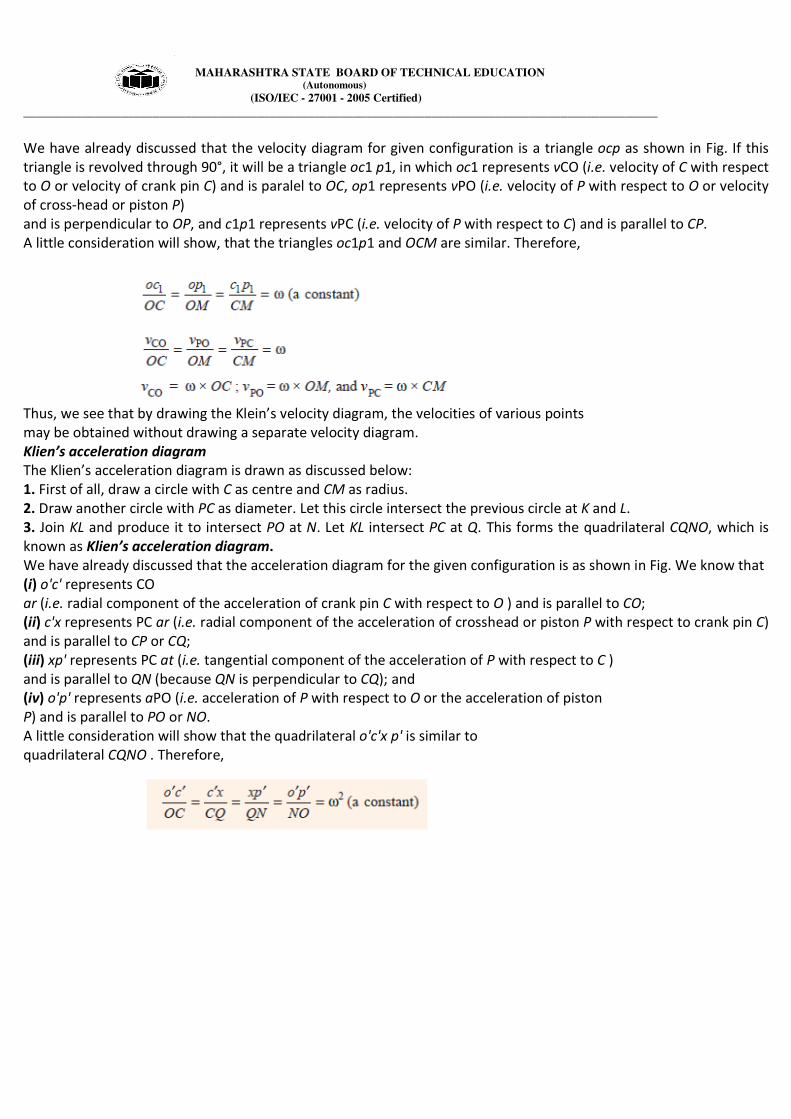
We have already discussed that the velocity diagram for given configuration is a triangle ocp as shown in Fig. If this
triangle is revolved through 90°, it will be a triangle oc1 p1, in which oc1 represents vCO (i.e. velocity of C with respect
to O or velocity of crank pin C) and is paralel to OC, op1 represents vPO (i.e. velocity of P with respect to O or velocity
of cross-head or piston P)
and is perpendicular to OP, and c1p1 represents vPC (i.e. velocity of P with respect to C) and is parallel to CP.
A little consideration will show, that the triangles oc1p1 and OCM are similar. Therefore,
Thus, we see that by drawing the Klein’s velocity diagram, the velocities of various points
may be obtained without drawing a separate velocity diagram.
Klien’s acceleration diagram
The Klien’s acceleration diagram is drawn as discussed below:
1. First of all, draw a circle with C as centre and CM as radius.
2. Draw another circle with PC as diameter. Let this circle intersect the previous circle at K and L.
3. Join KL and produce it to intersect PO at N. Let KL intersect PC at Q. This forms the quadrilateral CQNO, which is
known as Klien’s acceleration diagram.
We have already discussed that the acceleration diagram for the given configuration is as shown in Fig. We know that
(i) o'c' represents CO
ar (i.e. radial component of the acceleration of crank pin C with respect to O ) and is parallel to CO;
(ii) c'x represents PC ar (i.e. radial component of the acceleration of crosshead or piston P with respect to crank pin C)
and is parallel to CP or CQ;
(iii) xp' represents PC at (i.e. tangential component of the acceleration of P with respect to C )
and is parallel to QN (because QN is perpendicular to CQ); and
(iv) o'p' represents aPO (i.e. acceleration of P with respect to O or the acceleration of piston
P) and is parallel to PO or NO.
A little consideration will show that the quadrilateral o'c'x p' is similar to
quadrilateral CQNO . Therefore,
MAHARASHTRA STATE BOARD OF TECHNICAL EDUCATION (Autonomous)
(ISO/IEC - 27001 - 2005 Certified)
__________________________________________________________________________________________________
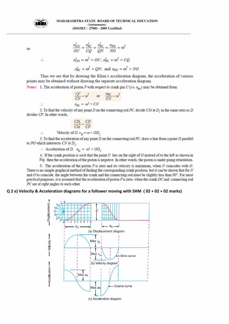
Q 2 e) Velocity & Acceleration diagrams for a follower moving with SHM ( 02 + 02 + 02 marks)

MAHARASHTRA STATE BOARD OF TECHNICAL EDUCATION (Autonomous)
(ISO/IEC - 27001 - 2005 Certified)
__________________________________________________________________________________________________
Q2 f) (For T1 & T2 values 02 marks, for width 02 marks)
Q3 a) Four bar link mechanism (Diagrams-02 marks, calculations -02 marks)
Data: Crank AB = 200 mm, BC = 400 mm, CD = 450 mm, fixed link AD = 600 mm,
W = 36 rad/sec, Crank angle = 450
P1 = mid point of link BC, P2 = on the link CD 100 mm from pin connecting link AD and CD
Space diagram velocity diagram

MAHARASHTRA STATE BOARD OF TECHNICAL EDUCATION (Autonomous)
(ISO/IEC - 27001 - 2005 Certified)
__________________________________________________________________________________________________
Velocity of crank AB, Vab = w x AB = 36 x 0.2 = 7.2 m/sec
With a certain scale draw ab perpendicular to link AB for Vab = 7.2 m/s.
Draw bc perpendicular to link BC and also draw cd perpendicular to link CD through point a or d as AD is a
fixed link.
From Velocity diagram, Velocity of midpoint p1 of link BC = 2.2 m/s,
Velocity of point p2 on the link CD = 1.4 m/s
Q3 b) Data: (Diagrams-02 marks, calculations -02 marks)
Crank OB = 125 mm, Conn. Rod AB = 500 mm, Angle of crank from IDC = 450
C.G. of Conn rod G = 275 mm from slider,
NBO = 600 rpm, WBO =2 π X 600/60 = 62.84 rad/s
Vector ob = VBO = VB = WBO x OB = 62.84 x .125 = 7.855 m/s
Configuration Diagram Velocity diagram
Velocity of slider Vector oa = Voa = 6.79 m/s
Velocity of conn. Rod Vector ab = VAB = 5.66 m/s
Velocity of point ‘G’ Vector og = Vg = 7.2 m/s

MAHARASHTRA STATE BOARD OF TECHNICAL EDUCATION (Autonomous)
(ISO/IEC - 27001 - 2005 Certified)
__________________________________________________________________________________________________
Q3 c) Advantages and disadvantages of chain drive over belt drive (02 + 02 Marks)
Q3 d) Working of centrifugal clutch ( fig 02 marks, explanation 02 marks)
The centrifugal clutches are usually incorporated into the motor pulleys. It consists of a number of shoes on
the inside of a rim of the pulley, as shown in Fig. The outer surface of the shoes is covered with a friction material.
These shoes, which can move radially in guides, are held against the boss (or spider) on the driving shaft by means of
springs. The springs exert a radially inward force which is assumed constant. The mass of the shoe, when revolving,
causes it to exert a radially outward force (i.e. centrifugal force). The magnitude of this centrifugal force depends
upon the speed at which the shoe is revolving. A little consideration will show that when the centrifugal force is less
than the spring force, the shoe remains in the same position as when the driving shaft was stationary, but when the
centrifugal force is equal to the spring force, the shoe is just floating. When the centrifugal force exceeds the spring
force, the shoe moves outward and comes into contact with the driven member and presses against it. The force with
which the shoe presses against the driven member is the difference of the centrifugal force and the spring force. The
increase of speed causes the shoe to press harder and enables more torque to be transmitted.

MAHARASHTRA STATE BOARD OF TECHNICAL EDUCATION (Autonomous)
(ISO/IEC - 27001 - 2005 Certified)
__________________________________________________________________________________________________
Q3 e) Process of balancing of single rotating masse by a single rotating mass in the same plane ( 04 marks)
Q3 f) Terms as applied to cams- (01 mark each)
i) Base circle: it is smallest circle that can be drawn to the cam profile.
ii) Pitch circle: it is the circle that can be drawn from the center of the cam through the pitch points.
iii) Pressure angle: it the angle between the direction of follower motion and a normal to the pitch curve.
iv) Stroke of the follower: it is maximum travel of the follower from its lowest position to the topmost position
MAHARASHTRA STATE BOARD OF TECHNICAL EDUCATION (Autonomous)
(ISO/IEC - 27001 - 2005 Certified)
__________________________________________________________________________________________________
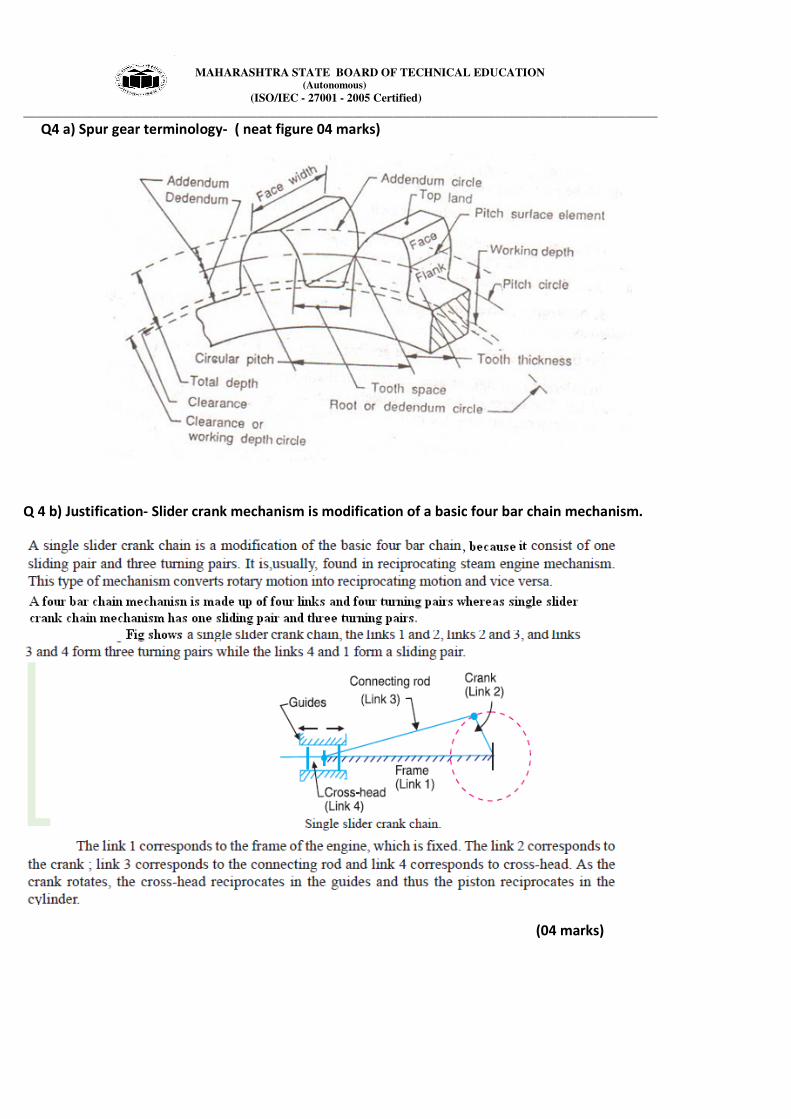
Q4 a) Spur gear terminology- ( neat figure 04 marks)
Q 4 b) Justification- Slider crank mechanism is modification of a basic four bar chain mechanism.
(04 marks)

MAHARASHTRA STATE BOARD OF TECHNICAL EDUCATION (Autonomous)
(ISO/IEC - 27001 - 2005 Certified)
__________________________________________________________________________________________________
Q 4 c) Comparison between flywheel and Governor (04 Marks)
Sr.N0. Flywheel Governor
1 Flywheel is a device which stores when
produced in excess & release when required
by m/c.
Governor is a device controls the supply of energy
of fuel to engine & controls mean speed.
2 It regulates fluctuation of speed when there
is a variation in cyclic torque of m/c
It regulates speed of engine when there is a
external load variation.
3 It acts by virtue of its inertia It acts as a mechanism to control fuel supply
4 If torque variation is high, flywheel required
is larger size.
If external load variation is higher, more control on
fuel supply necessary.
5 Used in Engines, forging m/c, Sheet metal
press, shearing m/c.
Used in Engines.
Q4 d) Eddy current dynamometer- ( Fig 02 marks, Explanation 02 marks)
Working principle: It consists of a stator on which are fitted a number of electromagnets and a rotor disc made of
copper or steel and coupled to the output shaft of the engine. When the rotor rotates , eddy currents are produced in
the stator due to magnetic flux set up by the passage of field current in the electromagnets. These eddy currents
oppose the motion of the rotor thus loading the engine. The eddy currents are dissipated in producing heat so that
this type of dynamometer also requires some cooling arrangements. The torque is measured similar to absorption
dynamometers i.e. with the help of moment arm. The load is controlled by regulating the current in the
electromagnets.

MAHARASHTRA STATE BOARD OF TECHNICAL EDUCATION (Autonomous)
(ISO/IEC - 27001 - 2005 Certified)
__________________________________________________________________________________________________
Q4 e) Problem on clutch (01 + 02 + 01 Marks)
Q4 f) Balancing of masses (Diagrams-02 marks, calculations -02 marks)
Data : m1 = 260 kg, m2 = 160 kg, m3 = 300 kg, m4 = 200 kg,
r1 = 300 mm = 0.3 m, r2 = 250 mm = 0.25 m, r3 = 150 mm = 0.15 m, r4 = 200 mm = 0.2 m
Ɵ1 = 00
Ɵ1 = 450 Ɵ1 = 90
0 Ɵ1 = 135
0

MAHARASHTRA STATE BOARD OF TECHNICAL EDUCATION (Autonomous)
(ISO/IEC - 27001 - 2005 Certified)
__________________________________________________________________________________________________
Q 5 (a) (Space diagram 02 marks, Velocity diagram 03 marks, each answer 01 marks)

MAHARASHTRA STATE BOARD OF TECHNICAL EDUCATION (Autonomous)
(ISO/IEC - 27001 - 2005 Certified)
__________________________________________________________________________________________________
Q 5 (b) (Displacement diagram 03 marks, Cam Profile 05 marks)

MAHARASHTRA STATE BOARD OF TECHNICAL EDUCATION (Autonomous)
(ISO/IEC - 27001 - 2005 Certified)
__________________________________________________________________________________________________
Q 5 (c) (Case 1 = 04 marks, Case 2 = 04 marks)
MAHARASHTRA STATE BOARD OF TECHNICAL EDUCATION (Autonomous)
(ISO/IEC - 27001 - 2005 Certified)
__________________________________________________________________________________________________
Q 6 (a) (i) (Sketch 02 marks, Working principle 02 marks)
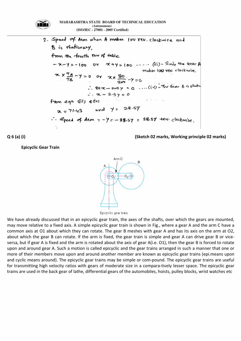
Epicyclic Gear Train
We have already discussed that in an epicyclic gear train, the axes of the shafts, over which the gears are mounted,
may move relative to a fixed axis. A simple epicyclic gear train is shown in Fig., where a gear A and the arm C have a
common axis at O1 about which they can rotate. The gear B meshes with gear A and has its axis on the arm at O2,
about which the gear B can rotate. If the arm is fixed, the gear train is simple and gear A can drive gear B or vice-
versa, but if gear A is fixed and the arm is rotated about the axis of gear A(i.e. O1), then the gear B is forced to rotate
upon and around gear A. Such a motion is called epicyclic and the gear trains arranged in such a manner that one or
more of their members move upon and around another member are known as epicyclic gear trains (epi.means upon
and cyclic means around). The epicyclic gear trains may be simple or com-pound. The epicyclic gear trains are useful
for transmitting high velocity ratios with gears of moderate size in a compara-tively lesser space. The epicyclic gear
trains are used in the back gear of lathe, differential gears of the automobiles, hoists, pulley blocks, wrist watches etc
MAHARASHTRA STATE BOARD OF TECHNICAL EDUCATION (Autonomous)
(ISO/IEC - 27001 - 2005 Certified)
__________________________________________________________________________________________________
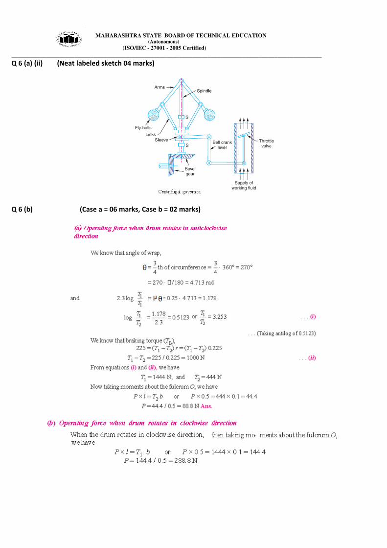
Q 6 (a) (ii) (Neat labeled sketch 04 marks)
Q 6 (b) (Case a = 06 marks, Case b = 02 marks)

MAHARASHTRA STATE BOARD OF TECHNICAL EDUCATION (Autonomous)
(ISO/IEC - 27001 - 2005 Certified)
__________________________________________________________________________________________________
Q 6 c
(i) Considering Uniform Pressure Condition
Frictional Torque, T = 2/3 µWR = 2/3 x 0.05 x (15 x 1000) x 7.5
= 3750 N-cm or 37.5 N-m ……………02 marks
Power lost in friction, P = 2πNT/60 x 1000 kW
= 2π x 100 x 37.5/60 x 1000
= 0.393 kW …………………………02 marks
(ii) Considering Uniform Wear Condition
Frictional Torque, T = 1/2 µWR = 1/2 x 0.05 x (15 x 1000) x 7.5
= 2812 N-cm or 28.12 N-m …………02 marks
Power lost in friction, P = 2πNT/60 x 1000 kW
= 2π x 100 x 28.12/60 x 1000
= 0.294 kW …………………………02 marks
----------------------------------------------------------------------------------------------------------------------------------------------------