Embed Size (px)
Citation preview

Maharashtra State Electricity Distribution Company Limited
SPEC. NO.
STORES: MSC-II/ DT/ 3Star 63,100KVA (non CSP with metering/2011
TECHNICAL SPECIFICATION
FOR
THREE STAR, THREE PHASE, 63, 100 kVA, 11/0.433 kV DISTRIBUTION TRANSFORMERS
WITHOUT CSP and with DTC metering
FOR
DISTRIBUTION SYSTEM
IN
MSEDCL

I N D E X
Clause No. Contents
1 Scope
2 System Particulars
3 Service Condition
4 Applicable Standards
5 Specific Technical requirement
6 Design & Construction
6.1 Core
6.2 Windings
6.3 Losses
6.4 Insulation Material & Clearances
6.5 Impedance Value
6.6 Tank
7 No CSP Protection
8 DTC metering Unit
9 Heat Dissipation and Total minimum oil volume
10 Conservator.
11 Breathers.
12 Terminals
13 Bushing and connections
14 Internal Connections
15 Tank base channel
16 Terminal Marking Plate & Rating Plate
17 Fittings
18 Lightning Arrestor
19 Transformer Oil
20 Tests & Inspection
21 Challenge Testing
22 Type Tests
23 Drawings
24 Rejection
25 Cleaning & Painting
26 Guaranteed Technical Particulars
27 Testing facilities

28 Submission of Routine Test Certificate
29 Stage Inspection
30 Testing for no load and full load losses of all
distribution transformers
31 Random Sample Testing
32 Inspection & Testing of Transformer Oil
33 Quality Assurance
34 Qualifying Requirements
35 Final Inspection
36 Performance Guarantee
37 Loading of transformers
38 Cost Data Sheet
39 Schedule
Schedule A Guaranteed and Other Technical Particulars
Schedule B Tenderer’s experience
Annexure-I Air Pressure Test
Annexure-II Unbalance Current Test
Annexure-III Temperature Rise Test
Annexure –IV Star Rating Labeling programme (Schedule -5 )
Annexure –V Indicative drawings

MAHARASHTRA STATE ELECTRICITY DISTRIBUTION COMPANY
TECHNICAL SPECIFICATION
THREE STAR, THREE PHASE, 63 kVA & 100 kVA, 11/0.433 DISTRIBUTION TRANSFORMERS
WITHOUT CSP FEATURE AND WITH DTC METERING UNIT
Tech. Spec. No.
STORES: MSC-II/ DT/ 3Star 63,100KVA (non CSP with metering/2011
1 Scope:-
This specification covers design, manufacturing, testing and delivery of Three Star, three phase,
63 kVA & 100 kVA, 11/0.433 , Oil immersed Oil Natural (ONAN), Outdoor type Distribution
Transformers without CSP feature and with DTC metering unit suitable for 11 kV, 50 Hz
Distribution System.
1.1 The equipment offered shall be complete with all parts necessary for their effective and trouble-free
operation. Such parts will be deemed to be within the scope of the supply irrespective of whether
they are specifically indicated in the commercial order or not.
1.2 It is not the intent to specify herein complete details of design and construction. The equipment
offered shall conform to the relevant standards and be of high quality, sturdy, robust and of good
design and workmanship complete in all respects and capable to perform continuous and
satisfactory operations in the actual service conditions at site and shall have sufficiently long life in
service as per statutory requirements.
1.3 The design and constructional aspects of materials shall not withstanding any anomalies,
discrepancies, omissions, in-completeness, etc. in these specifications and will be subject to good
engineering practice in conformity with the required quality of the product, and to such tolerances,
allowances and requirements for clearances etc. as are necessary by virtue of various stipulations in
that respect in the relevant Indian Standards, IEC standards, I.E. Rules, I.E. Act and other statutory
provisions.
1.4 The Bidder/supplier shall bind himself to abide by these considerations to the entire satisfaction of
the purchaser and will be required to adjust such details at no extra cost to the purchaser over and
above the tendered rates and prices.
1.5 Tolerances:
The tolerance of guaranteed performance figures shall be as specified in the (Part-I) table 7 of latest
issue of IS 2026 or relevant International Standard except wherever specified otherwise in this
specification.
2 System Particulars:-
The transformers shall be suitable for outdoor installation with following system particulars and they
should be suitable for service under fluctuations in supply voltage as permissible under Indian
Electricity Rules
2.1 Nominal System Voltage : 11 kV
2.2 Corresponding Highest System Voltage : 12 kV
2.3 Neutral earthing : Solidly earthed
2.4 Frequency : 50 Hz with ±3 % tolerance
2.5 Number of Phase : 3

3 SERVICE CONDITIONS:
3.1 Equipment supplied against the specification shall be suitable for satisfactory operation under the
following tropical conditions:-
i Max. ambient air temperature : 50 Deg. C
ii Max. relative humidity : 100 %
iii Max. annual rainfall : 1450 mm
iv Max. wind pressure : 150 kg/sq.m.
v Max. altitude above mean sea level : 1000 mtrs.
vi Isoceraunic level : 50
vii Seismic level(Horizontal acceleration) : 0.3 g.
viii Climatic Condition Moderately hot and humid tropical
climate conducive to rust and fungus
growth.
ix Reference Ambient Temperature for
temperature rise : 50 Deg C
3.2 The climatic conditions are prone to wide variations in ambient conditions and hence the equipment
shall be of suitable design to work satisfactorily under these conditions.
4 APPLICABLE STANDARDS:-
4.1 The design, manufacture and performance of the equipment shall comply with all currently
applicable statutes, regulations and safety codes.
Nothing in this specification shall be construed to relieve the bidder off his responsibilities.
4.2 The Distribution Transformers shall conform to IS: 2026 as amended up to date or other
International Standards for equal or better performance.
4.3 Unless otherwise specified, the equipment offered shall conform to latest applicable Indian, IEC,
British or U.S.A. Standards and in particular, to the following:-
a. IS 2026 (Part I,II,IV)/1997,
(Part-III)/1981, (Part-V)/1994
Power Transformer
b. IS:1180/1989 (Part-1) Outdoor type, Three phase distribution transformers up
to and including 100 kVA, 11KV
c. IS:335/1993 New insulating oil- Specification (fourth revision)
d. IS:2099/1986, IS: 7421-1988,
IS:3347 (Part-I /Sec-2)-1979,
IS:3347 (Part-I /Sec-1)-1982
amended up to date
Bushing
e. IS 5 Colours for ready mixed paints and enamels.
f. IS 13730 (Part-27)1996 Specification for particular types of winding wires.
g. IS: 3073/1974, IS: 3070( Part-
II)
Specifications for L.A’s

h. CBIP Publication No.295:2006 Manual on transformers
i. I.S. 13947/I/1993 Specification for low voltage switchgear & control gear
4.4 In case of conflict arising out due to variations between the applicable standard and the standards
specified herein the provisions of this specification should prevail.
5 Specific Technical requirement:
5.1 Standard kVA Ratings:-
The standard ratings for transformer shall be 63 kVA, 100 kVA.
5.2 Nominal voltage ratings
i Primary voltage : 11 kV
ii Secondary voltage : 0.433 kV
5.2.1 Winding connections:-
i. H.V. Winding : Delta (∆)
ii. L.V. Winding : Star (Y)
The neutral of the L.V. winding shall be brought out to a separate insulated terminal. The voltage
group shall be Dyn-11.
5.3 Temperature Rise:
i The temperature rise for top oil over an ambient temperature of 50° C should be 35°C maximum
(measured by thermometer in accordance with IS 2026).
ii Temperature rise for winding over an ambient temperature of 50° C should be 40° C maximum
(measured by resistance method in accordance with IS 2026).
5.4 No load voltage ratio:-
The no load voltage ratio shall be 11000/433 Volts.
6 Design & construction
6.1 Core
i The core shall be stacked/ wound type
a) For Stack core :- The core shall be of high grade cold rolled grain oriented (C.R.G.O) annealed
steel lamination having low loss and good grain properties, coated with hot oil proof insulation,
bolted together to the frames firmly to prevent vibration or noise. All core clamping bolts shall
be effectively insulated. The complete design of core must ensure permanency of the core losses
with continuous working of the transformers.
b) For Wound core :-
The core shall be ‘C’ type construction of high grade cold rolled grain oriented (C.R.G.O.)
annealed steel lamination having low loss and good grain properties, coated hot oil proof
insulation or Amorphous core material. The complete design of core must ensure permanency of
the core losses with continuous working of the transformers. The core material shall not be brittle
in case of CRGO material.
Core clamping for C.R.G.O./Amorphous Wound core type transformers shall be as follows:
1. Core clamping shall be with top and bottom U- shaped core clamps made of sheet steel
clamped.

2. M.S. core clamps shall be painted with oil-resistant paint.
3. Suitable provision shall be made in the bottom core clamp / bottom plate of the transformer
to arrest movement of the active part.
4. Core clamping shall be done with 12mm diameter MS Tie rods.
ii. The grade of core laminations shall be M4 or better.
The successful bidder, shall be required to submit the manufacturer’s test report showing the
Watt Loss per kg and the thickness of the core lamination, to ascertain the quality of Core
materials.
The purchaser reserves the right to get sample of the core material tested at any Government
recognized laboratory.
iii. The transformer core shall not be saturated for any value of V/f ratio to the extent of 112.5% of
the rated value of V/f ratio (i.e. 11000/50) (due to combined effect of voltage and frequency) up
to 12.5% without injurious heating at full load conditions and will not get saturated. The bidder
shall furnish necessary design data in support of this situation.
iv. Flux density:-
Flux density should not be more than 1.55 Tesla for CRGO transformers and 1.38 Tesla for
Amorphous Metal Core transformers at the rated voltage and frequency. The value of the flux
density allowed in the design shall be clearly stated in the offer along with graph.
v. The No load current at rated voltage shall not exceed the percentage given in Table below.
Sr.
No.
kVA
Rating
At Rated Voltage At 112.5 % Rated Voltage
1 63 (CRGO) 3% of the full load
current in LT winding
6 % of the full load
current
2 100 (CRGO) 2.5 % of the full load
current in LT winding
5 % of the full load
current
3 63 (AMDT ) 1.25 % of full load current
in LV winding
3.5% of full Load Current
4 100 (AMDT ) 1.1 % of full load current
in LV winding
3.0 % of full Load Current
i. Number of steps of core shall be minimum of
For 63 kVA 5 standard steps
For 100 kVA 5 standard steps
6.2. Winding:-
j. Materials:
Double paper covered Aluminium conductor shall be used for HV and LV winding for 11 kV
class.
ii Current Density:
Current density for HV and LV winding should not be more than 1.6 A / sq.mm for Aluminum
conductor.
iii L.V. Neutral formation shall be at top.

6.3 Losses :
The total losses (no load + load losses at 75 °C ) at 50% & 100% loading for three phase, three star
rating 63 kVA &100 kVA, 11 /0.433 kV distribution transformers at rated voltage, frequency and at
75 deg. C shall not exceed the values indicated as below:
TABLE – 1
KVA Rating Voltage Ratio
in kilovolts
Max. total Losses
at 50% loading of
kVA rating
(Watts)
Max. total Losses at
100% loading of kVA
ratings (Watts)
63 KVA 11/0.433 380 1250
100 KVA 11/0.433 520 1800
Tolerances:
No positive tolerance shall be allowed on the maximum losses given in the table for both 50 % &
100 % loading values. In case the actual loss values exceed the above guaranteed values, the
transformers shall be rejected at the risk, cost and responsibility of the supplier.
The values guaranteed in G.T.P. for flux density, no load current at rated voltage, no load current
at 112.5% of rated voltage and no load loss at rated voltage shall be individually met.
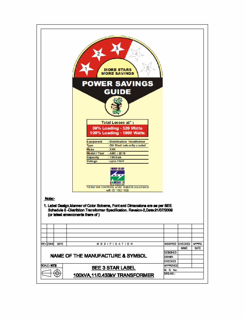
Note : Please refer Annexure IV i.e. Schedule 5 of the technical specifications for 3 star
distribution transformers given by Bureau of Energy Efficiency (the same is attached
with technical specification ). As per Govt. of India gazette notification dt. 06.07.2009
and BEE guidelines followed by Government of Maharashtra & B.R.1150 dt.
28.05.2010, it is compulsory to display Star label sticker on each supplied distribution
transformer at suitable place.
6.4 Insulation material & clearances:
i Materials - Makes of Electrical grade insulating craft paper, Press Board, Perma wood/ Haldi
wood insulation shall be declared in GTP by the bidder. The test reports for all properties as per
relevant I.S. amended up to date shall be submitted during inspection.
ii The electrical clearance between the winding and body of the tank (between inside surface of the
tank and outside edge of the windings) should not be less than 30 mm for 11 kV class.
Minimum external clearances of bushing terminals
11 kV
HV Ph to Ph 255 mm
Ph to E 140 mm
LV Ph-to-Ph 75 mm.
Ph to E 40 mm.

6.5 Impedance Value-
The percentage impedance at 75 º C. shall be 4.5% for 11 kV (IS tolerance of ± 10 % is applicable).
6.6 Tank
6.6.1 The transformer tank shall be made up of prime quality M.S. sheets of rectangular shape. No other
shape will be accepted. The transformer tank shall be of robust construction. All joints of tank and
fittings should be oil tight and no bulging shall occur during service. The tank design shall be such
that the core and windings can be lifted freely. The tank plates shall be of such strength that the
complete transformer when filled with oil may be lifted bodily by means of the lifting lugs provided.
Tank inside shall be painted by varnish. Top cover plate shall be slightly sloping; approximately 5 to
10 deg. towards HV bushing and edges of cover plate should be bent downwards so as to avoid entry
of water through the cover plate gasket. The width of bend plate shall be 25 mm min. The top cover
shall have no cut at point of lifting lug. The rectangular tank shall be fabricated by welding at
corners.
6.6.2 The transformer tank of corrugation is also acceptable, however shape of tank shall be rectangular
only. The corrugation sheets thickness shall be of minimum 1.6mm. Corrugation panel shall be used
for cooling. The transformer shall be capable of giving continuous rated output without exceeding
the specified temperature rise. Bidder shall submit the detailed calculation sheet alongwith offer. The
safe guard angle frame 50X50X5 mm shall be welded for corrugated side to the tank.
6.6.3 In rectangular shape tanks, horizontal or vertical joints in tank side walls and its bottom or top cover
will be not allowed. In addition the cover of the main tank shall be provided with an air release plug.
Side wall thickness : 3.15 mm. (min.)
Top and bottom plate thickness : 5 mm. (min.)
6.6.4 Reinforced by welded angle 50X50X5 MM on all the outside walls on the edge of tank to form two
equal compartments. The permanent deflection is not more than 5mm up to 750 mm length and 6mm
up to 1250 mm length when transformer tank without oil is subject to air pressure of 35 KPa above
atmospheric pressure for 30 min. Pressure test shall be performed carefully at the time of 1st stage
inspection only to confirm the adequacy of reinforcement angle and gauge of the tank and certified
by E.E. (IW).
6.6.5 All welding operations to be carried out by MIG process.
6.6.6 Lifting lugs: 2 nos. welded heavy duty lifting lugs of MS plate of 8mm thickness suitably
reinforced by vertical supporting flat of same thickness as of lug welded edgewise below the lug on
the side wall, up to reinforcing angle. They shall be so extended that cutting of bend plate is not
required. 2 nos welded heavy duty lifting lugs of MS Plate of 8 mm thickness should be on the top
plate of transformer.
6.6.7 Pulling lugs: 4 nos. of welded heavy duty pulling lugs of MS plate of 8mm thickness shall be
provided to pull the transformer horizontally.
6.6.8 Top cover fixing bolts: GI nut bolts of 3/8” dia. with one plain washer shall be used for top cover
fixing, spaced at 4” apart. 6mm neoprene bonded cork oil resistance gaskets conforming to type B/C
IS 4253 Part-II amended up to date will be placed between tank and cover plate.
6.6.9 Vertical clearance: - The height of the tank shall be such that minimum vertical clearance up to the
top cover plate of 120 mm is achieved from top yoke.

7.0 CSP Protection: No CSP feature is not required.
8.0 Tamper proof DTC METERING UNIT :
Tamper Proof DTC Metering Unit shall be manufactured in accordance with the following
Standards (as per drawing enclosed) Annexure –V.
The Metering unit shall comply with the requirement of IS:2147/1962 for Degree of Protection
I.P. 54.
General Technical Particulars:
This outdoor type Metering Unit shall be designed and fixed on the LV bushing side of the main
transformer tank. General arrangement of Metering Unit shall be kept as per drawing covering the
above aspect is enclosed at Annexure –IV. The overall dimensions of enclosure shall be such that it
should accommodate the LV Bushings, Three Ring Type CTs of rating 200/5 A, for 100kVA & 150/5
A for 63 kVA transformers, one LT CT operated Static TOD meter.
1. In First chamber-
The first chamber shall be provided as an enclosure to transformer L.V. bushings and CTs as shown
in diagram. The required minimum electrical clearances as per relevant IS, shall be maintained while
providing / fixing the box. The suitable rubber gasket shall be provided between transformer body
and enclosure so as rain water shall not enter in the chamber.
Three CTs of 5VA burden & class of accuracy 0.5 shall be mounted on fixed arrangement inside the
chamber for each phase as shown in the drawing. The inner diameter of CTs shall be suitable to
cover the cable size. CTs should be magnetically shielded and fixed inside the enclosure with
suitable nut bolts & washers.
Minimum 2.5 sq. mm. copper multistranded (flexible) wire shall be used for connections from CT
secondary terminals to Meter & P.T connections.
The Enclosure shall be fabricated by using CRCA sheet steel of 14 SWG (2mm) thickness & shall
comply with the requirement of I.P.-54 as per I.S. 2147/1962.
2. Second Chamber:
The energy meter shall be fixed on suitable arrangement keeping minimum clearance of 50 mm
from the tank surface. The clearances from Meter front side to enclosure shall be minimum 50 mm.
The Meter fixing arrangement shall be such that front and back as well as up and down with tilting
adjustment can be done to accommodate various type & make of meter (s). Also suitable space shall
be provided to install GSM MODEM alongwith the Antenna for future communication with the
meter.
Note : MSEDCL shall install any reputed make 3 phase, 4 wire static LT CT operated TOD energy
meters in the metering box.
Constructional main features of the Metering Unit are as under:
1. The single door panel shall be provided with 5 mm thick triplex glass window of size
150 mm x 115 mm – 1 nos for second chamber to facilitate meter reading.
2. One 6 mm isolated Earth Terminal in second chamber at side of the box.
3. Each LT Bushing provided with 2 nos. washer for lugs tightening.
4. Cam lock shall be provided to each chamber door with separate keys. The Two keys set shall
be supplied with each unit. e.g. Godrej cam lock.

5. 2 nos. earthing bolt size 25x10 mm each with 2 nos washer and one nut to be provided
6. 3 nos earth sticker with earth symbol to be provided.
7. 4 nos suitable size lugs for 70/ 120 sq.mm, 31/2 core PVC Al.Cable shall be provided
8. Danger marking 125 x 38 mm with Marathi language with 433 V AC.
9. Flat gasket of size 20 x 2 mm to be fixed with adhesive (fevibond) inside door
10. Inside hinges to be MIG welded strictly ( NO SPOT WELDING).
11. CT secondary & PT wires with proper lugs shall be connected to meter terminals.
12. Single panel doors for chamber 1 & 2.
13. Arrangement to be provided for holding the panel door manually
14. The sizes of each compartment & overall size shown are minimum and may be more to suit the
size of Transformer Tank and LT bushings.
15. The complete metering unit shall be as per Drawing enclosed so fitted with the transformer that
a gap of minimum 50 mm is maintained from the transformer tank & the unit for free
circulation of air & fitted towards the ground so that it is possible to take readings from a
distance of 2 to 3 meters.
16. The suitable cable glands shall be provided in first chamber for 3/12 cables.
17. Cable holding clamp shall be provided as shown in diagram. The cable holding clamp support
shall be welded on transformer tank.
Note: 1) All dimensions are in mm.
2) Chamber no.1& 2 Door - front open back
3) Sheet steel thickness: 2 mm (min)
4) Paint shade : Exterior & interior – Aircraft Blue at shade No 108 of IS 5.
5) Degree of enclosure protection IP : 54.
9.0 A) Heat Dissipation:
a. Heat dissipation by tank walls excluding top and bottom should be 500 W/ sq.meter.
b. Heat dissipation by fin type radiator 1.25 mm thick will be worked out on the basis of
manufacturers data sheet. The tenderer shall submit the calculation sheet with the offer or the offer
shall stand rejected.
c. Two nos. radiators shall be provided on HV side bushing and shall be of fin type. They should be
fixed at right angle to the sides and not diagonally. The size of the radiator shall be such that it
covers at least 50% of the bottom yoke, full core and complete top yoke.
B) Total Minimum Oil Volume :
Sr.No. KVA rating Voltage Ratio in
Volts
Oil in liters (exclusive of
oil absorbed in core &
coil assembly)
1 63 kVA 11000/433 155
2 100 kVA 11000/433 190
Note: The firm should maintain the oil volume in all supplied transformers as mentioned above.

10.0 Conservator:
a) The total volume of conservator shall be such as to contain 10% of total quantity of oil. Normally
3% quantity of the total oil will be contained in the conservator. Dimension of the conservator shall
be indicated on the General Arrangement Drawing.
b) Oil level indicator shall be provided on the side which will be with fully covered detachable flange
with single gasket and tightened with MS nut-bolt.
c) The inside diameter of the pipe connecting the conservator to the main tank shall be within 20 to 50
mm and it should be project into the conservator in such way that its end is approximately 20mm
above the totem of the conservator so as to create a sump for collection of impurities. The minimum
oil level (corresponding to (-) 5 deg.) should be above the sump level.
d) The pipe from conservator tank connecting to main tank shall be of 30 mm (min.) dia and shall have
a slopping flap so that the oil falling from the pipe shall not fall directly on the active job and shall
fall on the side walls only.
e) The conservator shall be provided with the drain plug and a filling hole (30mm dia) with cover.
11.0 Breather:
Breather joints will be screwed type. It shall have die-cast aluminum body or of Poly propylene
materials and inside container for silica gel shall be of tin sheet, in case of aluminum die cast
breather. Makes of the breather shall be subject to purchaser's approval. Volume of breathers shall
be suitable for 250 gm. of silica gel. The make and design of breather shall be subject to approval of
C.E. (Stores).
12.0 Terminals:
a. Brass rods 12 mm. diameter for HT with necessary nuts, check-nuts and plain thick tinned
washer.
b. Tinned Copper Rods of 12 mm diameter for 63/100 kVA distribution transformers for LT
extension with suitable cable lugs, necessary nuts, check-nuts and plain thick tinned washer.
13.0. Bushings & Connections:
13.1 For 11 kV (HV side), 12 kV Porcelain Bushing shall be used and for 433 volts (LV side), 1.0 kV
Porcelain Bushing shall be used. Bushings of the same voltage class shall be interchangeable. The
HV /LV Bushings assembly shall be as per relevant IS:3347 amended up to date. Porcelain part of
the LV bushings shall be as per IS: 3347 and Porcelain part of the HV bushings shall be as per IS
8603 (part I & III)-1977 (for heavily polluted atmosphere). The rated values, performance
requirements & tests for HV/LV Bushings shall be in accordance with IS 2099-1986. The Clamping
arrangement of 12 kV porcelain Bushings shall be accordance with IS: 4257 (part I)-1981.
13.2 HV Bushings shall be mounted on top cover of the transformer and LV Bushings shall be fixed on
tank body at equidistance throughout on opposite side of HV Bushings.
13.3 HV bushings shall be mounted on curvature shaped embossed plate, in such a way that all H.V.
Bushings shall remain parallel and at equi-distance throughout. Bushings having type tested, as per
relevant IS amended up to date shall only be acceptable.
13.4 The minimum creepage distance for both HV & LV Bushings shall not be less than 25 mm per kV.
14.0 Internal connections:
14.1 H.V. Winding :
i. In case of H.V. winding all jumpers from winding to bushing shall have cross section larger than
winding conductor.

ii. Inter coil connection shall be by crimping and brazing.
iii. In case of Copper Winding Delta joints shall be with crimping and Brazing only.
iv. Lead from delta joint shall be connected to bushing rod by brazing only.
14.2 L.V. Winding :
i. L.T. Star point shall be formed of Aluminium/Copper flat of sufficient length. Lead from
winding shall be connected to the flat by crimping and brazing.
ii. Firm connections of L.T. winding to bushing shall be made of adequate size of `L' shaped flat.
Connection of L.T. Coil lead to `L' shape flat shall be by crimping and brazing. Alternatively `L'
shape lug of adequate capacity effectively crimped shall be acceptable.
iii. ̀ L' shape flat/lug shall be clamped to L.V. Bushing metal part by using nut, lock-nut and washers.
iv. For Aluminum windings, L&T Alkapee aluminum brazing rods with suitable flux shall be used.
For copper winding crimping and silver brazing alloy shall be used.
15.0 Tank base channel :
It should be of two numbers of 75 mm x 40 mm channel for 63 kVA and 100 kVA transformers.
16.0 Terminal Marking Plates and Rating Plates :
Terminals shall be provided with terminal marking plates. The transformer shall be provided with
riveted rating plate of minimum 18 SWG aluminum anodized material sheet in a visible position.
The entries of the rating plate shall be in indelibly marked (i.e. by etching, engraving or stamping).
Marking as `M.S.E.D.C.L'S and `Sr. No.' of transformer shall be engraved on transformer main tank
below L.T. bushings.
The name of the company, order No., capacity, month and year of manufacturing shall be engraved
on separate plate which shall be firmly welded to main tank and shall form integral part of the tank.
17.0 Fittings:
The fittings on the transformers shall be as under:
1 Rating and diagram plate 1 no.
2 Earthing terminals with lugs. 2 no.
3 Lifting lugs 4 no. ( 2 nos to top plate of
transformer and 2 nos of
transformer tank )
4 Oil filling hole with cap(on conservator) 1 no
5 Drain valve - 20mm for all T/Fs (Metallic cover
spot welded to tank for drain valve shall be
provided).
1 no
6 Conservator with drain plug. 1 no
7 Thermometer pocket 1 no
8 Explosion vent (Only for 22 kV T/F) 1 no
9 Silica gel breather (250 gms) 1 no
10 Platform mounting channel 2 no
11 Oil level gauge indicating 3 positions of
marking as below :
1no
Minimum (-) 5 deg.C.

Normal 30 deg.C
Maximum 98 deg.C.
12 HT & LT bushing 3 nos. of HT bushing and 4 nos.
of LT bushing shall be
provided.
Each bushing (HV & LV)
should be provided with 3 nos.
of brass nuts and 2 plain brass
washers.
13 Radiators As per Cl. No. 8 (C)
14 Lightening Arrestors for HV Bushings 3 nos
15 Pulling lugs 4 nos
16 CSP feature operating handle 1 No
17 DTC metering Unit 1 No.
18.0 Lightening Arrestors:
The Lightening Arrestors (Disconnector type) of high surge capacity of 9 kV( Vrms), 5 kA( 8/20
micro wave shape) for 11 kV class transformers and 18 kV( Vrms), 5 kA ( 8/20 micro wave shape)
for 22 kV transformers conforming to IS: 3070/1974 shall be mounted on the HV bushings of
transformer, clamped securely to the tank, to protect the transformer and associated line equipment
from the occasional high voltage surges resulting from lighting or switching operations. The earthing
terminal of the lightening arresters shall be grounded separately.
19.0 Transformer Oil
Transformer oil to be used in all the Distribution transformers shall comply with the requirements of
latest IS 335/1983 amended up to date thereof. In addition the oil should conform to `Ageing
Characteristics’ specified below for New Oil and Oil in Transformers. Type test certificates of oil
being used shall be produced to EE (IW) at the time of stage inspection.
New oil - Ageing characteristics after accelerated ageing test 96 hrs at 115° C (open beaker method
with copper catalyst):
i. Specific Resistance (Resistivity)
a) at 20 º C :- 2.5 x 10 12
Ohm-Cm (Min)
b) at 90 º C :- 0.2 x 10 12
Ohm-Cm (Min)
ii. Dielectric dissipation factor - 0.20 (Max.tan delta) at 90 º C.
iii. Total acidity mg/KOH/gm - 0.05 (Max)
iv. Total sludge value (%) by weight - 0.05 (Max.)
v. The method of testing these aging characteristics is given in Appendix - C of IS 335 amended up
to date.
vi. Oil filled in Transformers:
The important characteristics of the transformer oil after it is filled in the transformer (within 3
months of filling) shall be as follows: -

Sr.No. Characteristics Specifications
1. Electric Strength (Breakdown voltage) 30 kV (Min)
2. Dielectric dissipation factor (Tan Delta) at 90 deg.C.) 0.01 (Max)
3. Specific Resistance (Resistivity) at 27 deg. C (ohm-cm) 10 x 10 12
4. Flash Point, P.M. (closed) 140 º C (Min)
5. Inter facial tension at 27 º C. 0.03N/M (Min)
6. Neutralization value (total acidity) 0.05Mg.KOH/gm
(Max.)
7 Water content PPM 35 (Max)
20.0 Test and Inspection:-
20.1 Routine Tests:-
i. All transformers shall be subjected to the following routine tests at the manufacturer's works. The
tests are to be carried out in accordance with the details specified in IS 2026 or as agreed upon
between the purchaser and the manufacturer.
1. Measurement of winding resistance.
2. Ratio, polarity and phase relationship.
3. Impedance voltage.
4. Load losses.
5. No-load losses and No-load current.
6. Insulation resistance.
7. Induced over voltage withstand.
8. Separate source voltages withstand.
ii. All the routine tests shall be conducted in the suppliers' laboratory at their cost.
iii. Heat run test shall be arranged free of cost on the unit selected from the 1st lot by Executive
Engineer / Authorized Representative.
iv. The calculations to confirm the thermal ability as per Clause no. 9.1 of latest IS: 2026 Part-I or
equivalent International Standard shall be submitted to Executive Engineer (IW).
21.0 Challenge Testing:
The manufacturer can also request challenge testing for any test based on specification and losses.
The challenger would request for testing with testing fees. The challenge test fees are proposed at
least three times the cost of testing. This is likely to deter unnecessary challenges. The challenger
would have the opportunity to select the sample from the store and any such challenge should be
made with in the guarantee period. The party challenged, challenger and the utility could witness the
challenge testing.
The challenge testing would cover following tests:
1. Measurement of magnetizing current.
2. No load losses test.
3. Load losses test (at 50 % loading or as per acceptance test).
4. Temperature rise test.

The challenge test could be conducted at NABL Laboratory, like ERDA and CPRI. If the values are
within the limits the products gets confirmed else not confirmed. No positive tolerances in losses is
permitted. If the product is not confirmed the manufacturer would pay the challenge fee and
challenger would get the fee refunded. However as a redressal system the challenger would be allow
to ask for fresh testing of two or more samples from the store and the same be tested in NABL
Laboratory in presence of party challenge, challenger and the utility.
If any one of the above sample does not confirm the test, then the product is said to have failed the
test. In such cases the manufacturer will be declared as unsuccessful manufacturer for the said
product with wide publicity and would not allow to complete in tenders of the MSEDCL for the
period of three years and heavy penalty would be imposed.
22.0 Type Tests:-
22.1 In addition to routine test as above Impulse voltage Withstand test and Dynamic Short Circuit Test
as under shall be successfully carried out at laboratories accredited by National Accreditation Board
for Testing and Calibration Laboratories (NABL)in accordance with IS 2026/1977 as amended from
time to time and technical specifications, within the last 5 (five) years prior to the date of offer. The
bidder shall furnish the following type tests reports (along with General arrangement drawing, Core
& Core details, Internal construction, HV& LV Bushing Assembly and Rating and Diagram Plate
drawings ) along with the offer.
i. Impulse Voltage with stand Test shall be carried out as per Clause No. 13 of IS 2026 (Part-III)/81
on all three HV phases chopped on tail. Impulse Voltage shall be 75 kVp for 11 kV class
transformers.
ii. Dynamic Short circuit Test
22.2 The following balance type test should be carried at the manufacturer’s works invariably in the
presence of MSEDCL’s representative at the time of inspection from the first lot.
i. Temperature Rise Test
ii. Air pressure test as per clause no. 22.5 of IS:1180 (Part I)/1989
iii. Unbalanced current test – unbalanced current should not be more than 2% of full load current
22.3 The type test reports should be submitted and got approved from the Chief Engineer (Stores) before
commencement of supply.
22.4 In case of any of the following, the offer may be considered for placement of order.
i. If above tests are carried out beyond 5 years
ii. Impulse Voltage Withstand test and Dynamic Short Circuit test carried out not from NABL
approved Laboratory.
iii. If there is any change in the design/ type of old type tested transformers to be offered against this
specification.
However, successful bidders have to carry out the type tests at the laboratories accredited by NABL
before commencement of supply at their own expense on the sample drawn by the purchaser from
the lot offered for first Stage Inspection.
22.5 In respect of the successful bidder, the purchaser reserves the right to demand repetition of some or
all the type tests in presence of the purchaser’s representative. In case the unit fails in the type tests,
the complete supply shall be rejected. The bidders are therefore requested to quote unit rates for
carrying out each type test, which however, will not be considered for evaluation of the offer.
23.0 Drawings:-
23.1 A set of following drawings with all dimensions shall be submitted by the Bidder along with the
offer:

i. General Dimensional.
ii. Core & Core Details (technical Details).
iii. Internal Construction.
iv. Rating & Diagram Plate.
v. HV/LV Bushings Assembly indicating measurement of creepage distances.
vi. Operation and Maintenance Manual.
vii. Outline General Arrangement for kVA Dist.Transformer -MSEDCL/MMII/63-100DT/01
viii.Meter Box & C.T. Mounting Box Arrangement for 63&100 kVA Dist.Transformer
MSEDCL/MMII/63-100DT/02.
ix. Meter Box & C.T. Mounting Box Arrangement for 63&100 kVA Dist.Transformer -
MSEDCL/MMII/63-100DT/03.
x. Meter Box with Meter for 63&100 kVA Dist.Transformer - MSEDCL/MMII/63-100DT/04.
23.2 The drawings shall be of A-3 (420 x 297 mm) size only. The bidder should also supply along with
his offer the pamphlets/literatures etc. for fittings / accessories. Indicative Drawings are attached
with the technical specifications for ready reference.
23.3 The bidder should not change design once offered as per A/T, Approved drawings and Type Test
Reports.
23.4 The successful Bidders shall submit complete set of Drawings (as listed in Cl.No.23.1) of
transformer in triplicate indicating dimensions to CE (Stores ) for approval and get approved before
commencement of supply.
24.0 Rejection :-
24.1 Apart from rejection due to failure of the transformer to meet the specified test requirements the
transformer shall be liable for rejection on any one of the following reasons.
i. At 50 % & 100% Loading condition, total losses exceeds the specified values mentioned in
Cl. No.6.3 above.
ii. Impedance voltage value exceeds the Guaranteed value plus tolerances as mentioned at
Cl..No.6.5 above.
iii Type test are not carried out as per clause no. 22.0 of the specification.
iv. Drawings are not submitted as per clause no. 23.0 of the specification.
v. GTP not submitted as per clause no. 26.0 of the specification.
vi Heat dissipation calculation sheet are not submitted as per clause no.8.0 of the specification.
25.0 Cleaning and Painting.
i. The surface of the tank shall be properly pre-treated / phosphated in a seven tank process and
shall be applied with a powder coating of 40 micron thickness. The powder coating shall be of
Aircraft Blue colour ( shade No. 108) for transformers. Powder coating shall be suitable for
outdoor use conforming IS: 13871/1993 – Powder coatings. The seven tank process facility shall
be enhance to ensure proper quality for outdoor application.

ii. The month and year of supply shall be painted in Red bold Marathi lettering at two places, one
on conservator and other at sum conspicuous place on the transformer which shall be clearly
visible from the ground.
26.0 Guaranteed & Technical Particulars:
The bidder should fill up all the details in GTP parameter list, the statement such as “as per drawings
enclosed”, “as per MSEDCL’s requirement” “as per IS” etc. shall be considered as details are not
furnished and such offers shall liable for rejection.
27.0 Testing facility
The bidder should have adequate testing facility for all routine and acceptance tests and also
arrangement for measurement of losses, resistance, etc. details of which will be enumerated in the
tender.
28.0 Submission Routine Test Certificate
a. The successful bidder shall submit the routine test certificate along with documentary evidence for
having paid the Excise Duty for the following raw materials viz. Oil, Aluminum, copper for
conductors, insulating materials, core materials, bushings at the time of routine testing of the fully
assembled transformer
b. The successful bidder shall be required to submit 5 copies of instruction and Operation manual for
each lot of 100 Transformers (or part thereof) supplied. This instruction manual should give
complete details about the pre-commissioning tests/checks and the details of preventive
maintenance etc.
29.0 Stage Inspection :-
29.1 Supplier shall give 15 days’ advance intimation to the Chief Engineer (Stores) and S.E. (Store/Adm)
to organize stage inspection in which assembly of core, windings and other core materials etc. would
be inspected. In respect of raw materials such as core stamping, winding conductor, oil etc.
successful bidder shall use these materials manufactured/supplied by the standard manufacturers and
furnish the manufacturer's test certificates, as well as, proof of purchase from those manufacturers
documentary evidence for having paid the excise duty for the information of the department.
29.2 Chief Engineer (Stores ) will depute representatives from testing and inspection wing at the time of
stage inspection.
29.3 10 % of the transformers from the offered lot will be tested for acceptance tests at factory, in the
presence of purchaser's representative before dispatch.
29.4 The inspection may be carried out by the purchaser at any stage of manufacture. The successful
bidder shall grant free access to the purchaser's representatives at a reasonable time when the work is
in progress. Inspection and acceptance of any equipment under this specification by the purchaser
shall not relieve the supplier of his obligation of furnishing equipment in accordance with the
specifications and shall not prevent subsequent rejection if the equipment is found to be defective.
29.5 The purchaser may at its option, open a transformer supplied to the Stores, in presence of supplier at
site or at Stores. If any of the technical particulars are seen to be in variance than the guaranteed
technical particulars, the whole lot of transformer will be rejected without any liability on purchaser.
29.6 In addition to the above, the purchaser may pick up any transformer and decide to get it type tested
from any laboratory accredited by NABL at purchaser's cost. The Bidder will have to organize
packing of the transformer at company's Stores for which they will be paid necessary charges. If the
transformer fails to meet the requirement of type tests, the quantity of transformers ordered on them

will be forthwith rejected and the purchaser may purchase these transformers at the risk and cost of
the supplier.
30.0 Testing for no load and full load losses of all Distribution Transformers:
After inspection of new transformers at factory for acceptance of the lot, all distribution transformers
from the lot will be tested for no load and full load losses at all stores. Tenderer has liberty to be
present at the time of testing.
31.0 Random Sample Testing (RST)
The tenderer should intimate to C.E. (Stores), M.S.E.D.C.L of completion of dispatches of whole lot
of Distribution Transformers to stores against this tender. C.E. (Stores), M.S.E.D.C.L for will select
the stores for Random Sample Testing (RST) and depute E.E. (Testing) to carry out RST of the lot.
E.E. (Testing) will select a transformer from the lot of transformers already tested for No load & full
load losses.15 days advance intimation will be given to tenderer for joint inspection. The date of
RST will not be altered to the convenience or request of supplier. If supplier’s representative fails to
attend on the date fixed for RST, the RST will be carried out in his absence and results of RST will
be binding on supplier. In case the selected transformer fails in any of the tests, complete lot of
transformers will be rejected.
32.0 Inspection & Testing of Transformer Oil:
The tenderer shall make arrangements for testing of transformer oil to be used in the transformers
and testing will be done in presence of purchaser's representative.
To ascertain the quality of transformer oil, original manufacturer's test report should be furnished to
EE (Testing) at the time of factory inspection for acceptance of the lot.
33.0 Quality Assurance:
33.1 The bidder shall invariably furnish following information along with the offer failing to which the
offer will be rejected.
33.2 Certificates of following materials.
i. Aluminium and copper conductor
ii. Transformer oil
iii. Core
iv. Insulating paper.
v. Porcelain Bushings
vi Steel Plate used for Tank
33.3 Names of the supplier for the raw material, list of standard accordingly to which the raw materials
are tested, list of test normally carried out on raw materials in presence of bidder’s representatives,
copies of type test certificates.
33.4 Information and copies of test certificate as in (i) above respect of bought out accessories including
terminal connectors.
33.5 List of manufacturing facilities available. In this list the bidder shall specifically mention whether
lapping machine, vacuum drying plant, air conditioned dust free room with positive air pressure for
provision of insulation and winding etc are available with him.
33.6 Level of automation achieved and list of areas where manual processing still exists.
33.7 List of areas in manufacturing process where stage inspection are normally carried out for quality
control and details of such tests and inspections.

33.8 Special features provided in the equipments to make it maintenance free.
33.9 List of testing equipment available with the bidder for final testing of transformers and test plant
limitation, if any, vis-à-vis the type, special acceptance and routine tests specified in the relevant
standards and the present specification.
33.10 The successful bidder shall submit the Routine Test Certificate along with documentary
evidence having paid for the excise duty for the following raw materials viz Oil, Aluminum for
conductors, insulating materials, Core materials, Bushing at the time of routine Testing of the fully
assembled transformer.
34.0 Qualifying Requirement: As per Tender
35.0 Final Inspection:
10 % of the transformers offered will be tested for all tests without opening the transformer. Heat
Run Test will have to be carried out on the transformer having maximum no load and full load losses
taken together. Chief Engineer (Stores) will depute representatives from testing and inspection
wing at the time of final inspection.
36.0 Performance Guarantee:
All transformers supplied against this specification shall be guaranteed for a period of 66 months
from the date of receipt at the consignee’s Stores Center or 60 months from the date of
commissioning, whichever is earlier. However, any engineering error, omission, wrong provisions,
etc. which do not have any effect on the time period, shall be attended to as and when observed/
pointed out without any price implication.
37.0 Loading of Transformer: The distribution transformers shall comply with IS: 6600.
38.0 COST DATA SHEET:-
The bidders shall submit the cost data sheets indicating the break up prices and quantity of each raw
material and components along with the unit rates required for manufacture the offered transformers
along with the offer. The cost data sheet format is enclosed herewith.. If the rates quoted are not
justified with the cost data sheets, the offer shall not be considered for evaluation and placement of
the order.
The cost data sheets shall be scrutinized by MM CELL section.
FORMAT FOR COST DATA
ITEM ------ KVA , ------- KV DISTRIBUTION TRANSFORMER
Sr.
No. PARTICULARS UNIT
UNIT
RATES
Rs.
QTY AMT (Rs.)
1 CORE (M4 or better ) KG
2 ALUMINIUM/COPPER
WITH DPC KG
3 INSULATION PAPER Meter
4 OIL LTRS
5 TANK NO
6 CHANNELS KG
7 INSULATORS/BUSHINGS KG

8 OTHERS LUMP
SUM
TOTAL
WASTAGE @ %
39.0 Schedules:
39.1 The bidder shall fill in the following schedules which form part of the tender specification and offer.
If the schedules are not submitted duly filled in with the offer, the offer shall be rejected.
Schedule `A' -Guaranteed Technical Particulars
Schedule `B' -Schedule of Tenderer's Experience.
39.2 The discrepancies between the specification and the catalogs, Literatures and indicative drawings
which are subject to change, submitted as part of the offer, shall not be considered and representation
in this regard will not be entertained.
39.3 The Bidder shall submit the list of orders for similar type of equipments, executed of under execution
during the last three years, with full details in the schedule of Tenderer's experience (Schedule `B') to
enable the purchaser to evaluate the tender.

Schedule `A'
GUARANTEED TECHNICAL PARTICULARS
As indicated in E-Tendering GTP Parameter

SCHEDULE – ‘B’
SCHEDULE OF TENDERER'S EXPERIENCE
Tenderer shall furnish here a list of similar orders executed/under execution by him to whom a reference
may be made by Purchaser in case he considers such a reference necessary.
-----------------------------------------------------------------------------------------------------------------
Sr. Name of client Value Period of supply Name & Address to
No. & Description. Of Order & commissioning whom reference may
(along with cap. be made.
of T/F)
-----------------------------------------------------------------------------------------------------------------
1 2 3 4 5
-----------------------------------------------------------------------------------------------------------------
NAME OF FIRM _________________________________
NAME & SIGNATURE OF TENDERER_______________
DESIGNATION____________________________________
DATE ____________________________________________

Annexure I
Air Pressure Test
Name of Supplier:
Order No.:
Capacity & Voltage Ratio of Distribution Transformer : ______ kVA, ____/0.433 kV
Vector Group Dyn11
Sr. No. of equipment Tested:
Date of Testing:
Reference Standard
All the opening of the transformer tank were closed with suitable gasket, bushing, valves and plugs.
The compressor pipe connected at oil filling hole on conservator and a pressure guage was fitted at air vent
plug. The parallel string were places around the tank, the distance between string and tank as shown in
following diagram were recorded before applying the pressure and after releasing pressure.
Tank Thickness: Side _________ mm. Top & Bottom ________ mm
Test Pressure : ______ kg/cm2
applied for 30 Minutes.
Test Point Distance before Test
In mm
Distance after release
of Pressure in mm
Deflection
In mm
A
B
C
D
Permanent Deflection : ________ mm
Permissible Limit of Permanent Deflection as per Specification : _____ mm
Test witnessed by Tested by

Annexure II
Unbalance Current Test
Name of Supplier:
Order No.:
Capacity & Voltage Ratio of Distribution Transformer : ______ kVA, ____/0.433 kV
Vector Group Dyn11
Sr. No. of equipment Tested:
Date of Testing:
Reference Standard
Transformer Secondary terminals 2U, 2V & 2W are shorted. The shorted 2U, 2V & 2W is connected
to 2N through Ammeter. The primary terminals 1U, 1V & 1W are connected to supply. The rated current
_____ A is fed to primary and unbalance current is noted on Ammeter.
Unbalance Current Measured in Ammeter : ______ A
Rated current in Secondary Side : ____________ A
Permissible limits as per specification : 2% of the Rated current in Secondary Side
% of Unbalance current with reference to Rated current in Secondary Side
Unbalance Current x 100 =
Rated current in Secondary Side
=
=
Test witnessed by Tested by

Annexure III
Temperature Rise Test
Name of Supplier:
Order No.:
Capacity & Voltage Ratio of Distribution Transformer : ______ kVA, ____/0.433 kV
Vector Group Dyn11
Sr. No. of equipment Tested:
Date of Testing:
Reference Standard
H. V. Winding L. V. Winding
Rated Line Current in Amp
Guaranteed No Load Losses ________ watt
Load Losses ________ watt
Total Losses ________ watt
P. T. Ratio : _______/____ =
C. T. Ratio : _______/_____ =
Wattmeter Constant =
Total Multiplying Factor (MF) =
Ambient Temp.
TIM
E
T1 °
C
T2 °
C
T3 °
C
Aver
age
°C
Top O
il T
emp. °C
Ris
e in
Top O
il T
emp. °C
Lin
e V
olt
age
in V
olt
s
Lin
e C
urr
ent
in A
mps
W1 w
atts
W2 w
atts
W3 w
atts
W1+
W2
+W
3 w
att
Mult
iply
ing F
acto
r (M
F)
Tota
l W
att
Reduced to Rated Current ________ amps
Calculation of Temperature Rise in Winding
LV Winding : Since the resistance of LV winding is less than 0.005 ohm, Temperature Rise in LV Winding
is taken as temperature rise of oil as per clause no. 4.3 of IS:2026 (Part II)/1977
Temperature Rise in LV Winding = __________ °C
HV Winding Resistance across 1U1V at _______°C = _______ ohm

Measurement of Hot Resistance of HV Winding after Shut Down.
Time Resistance
Hot winding Resistance at Ambient Temperature _________ °C (from graph) = _______ Ohm
Temperature Rise in H. V. Winding is
Hot Resistance x(235+Cold Ambient Temperature) =
Cold Resistance - (235+Hot Ambient Temperature
=
=
Results :
1) Temperature Rise in Oil = _________ °C
2) Temperature Rise in LV Winding = _________ °C
3) Temperature Rise in HV Winding = _________ °C
Test witnessed by Tested by

Annexure – IV
Revision: 2
Date: 21/07/2009
Schedule 5 – Distribution Transformer
Technical Specifications - Distribution Transformer
1. 0 Scope
1.1 This standard specifies the requirements for participating in the pilot energy labeling scheme for
oil immersed, naturally air cooled, three phase, and double wound non sealed type out door
distribution transformer.
1.2 The referred Indian Standard are IS 1180 (part I) Out door type three- phase Distribution
transformers upto and including 200 kVA, 11 kV – specification, IS:2026 (part 2)
Specifications of power transformers – for Temperature-rise and IS :2500 (part-I) -2000: Sampling
Schemes indexed by Acceptance Quality Limit (AQL) for lot-by-lot inspection.
1.3 The standard ratings covered under the pilot energy labeling scheme is 16, 25,
63, 100, 160 and 200 kVA and non standard ratings from 16 kVA to 200 kVA.
2.0 Schedule of Tests:
2.1 Method of Tests:
The testing code and procedure for distribution transformer would be as per IS 1180 (part 1): 1989 with all amendments as of date. The exception is conditions on limits of temperature rise. For the scheme the following would be used. Reduce the temperature rise limits of top oil and transformer winding from the existing IS 1180 (part 1): 1989 level of 45
0 C & 55
0 C to 35
0 C & 40
0 C.
2.2 Parameters to be tested:
Parameters for initial testing the type test parameters set out in IS 1180 (part 1) and the same is reproduced below: a. Measurement of winding resistance [IS 2026 (part I):1977] b. Measurement of voltage ratio and check of voltage vector relationship [IS 2026 (part I):1977] c. Measurement of impedance voltage/short circuit impedance and load loss [IS 2026 (part I):1977] d. Measurement of no-load loss and current [IS 2026 (part I):1977] e. Measurement of insulation resistance [IS 2026 (part I):1977] f. Induced over-voltage withstand test [IS 2026 (part 3):1981] g. Separate-source voltage withstand test [IS 2026 (part 3):1981] h. Lightning impulse test [IS 2026 (part 3):1981] i. Temperature-rise test [IS 2026 (part 2):1977] j. Short-circuit test [IS 2026 (part I):1977] k. Air pressure test [IS 1180 (part 1): 1989] l. Permissible flux density and over fluxing [IS 1180 (part 1): 1989]
Revised Schedule dated 14th
Aug 2007
1

Parameters for verification & challenge testing are as follows:
a. Measurement of winding resistance [IS 2026 (part I):1977] b. Measurement of impedance voltage/short circuit impedance and load
loss [IS 2026 (part I):1977] c. Measurement of no-load loss and current [IS 2026 (part I):1977] d. Temperature-rise test [IS 2026 (part 2):1977]
3.0 Tolerances:
No positive tolerance shall be allowed on the maximum losses displayed on the label for both 50% & 100% loading values.
4.0 Star rating plan:
4.1 Basis:
The existing efficiency or the loss standards are specified in IS 1180 (part 1). This standard defines load losses and no load losses separately. For the BEE labeling programme total losses at 50% and 100% load have been defined. The highest loss segment is defined as star 1 and lowest loss segment is defined as star 5. The existing IS 1180 (part 1) specification losses are the base case with star 1.The basis for star rating plan is as follows:
Case
Basis of losses (Total at 50% Load Condition)
Base case Star 1 Current purchasing practice (IS 1180 (part 1)Max Losses) Star 2 Star 3 Star 4
Star 5
4.2. Star Rating plan:
Some utility purchase specs like AP, NDPL Losses from TOC design (Moderate) Losses from lowest TOC design
High efficiency design
The total losses at 50% and 100% loading shall not exceed the values given below: Rating
1 star
2 star
3 star
4 star
5 star
kVA Max Max Max Max Max Max Max Max Max Max
Losses Losses Losses Losses Losses Losses Losses Losses Losses Losses at 50% at at 50% at at 50% at at 50% at at 50% at (Watts)
16 200
25 290
100% (Watts)
555
785
(Watts)
165
235
100% (Watts)
520
740
(Watts)
150
210
100% (Watts)
480
695
(Watts)
135
190
100% (Watts)
440
635
(Watts)
120
175
100% (Watts)
400
595
63 490
100 700
1415 430
2020 610
1335 380
1910 520
1250 340
1800 475
1140 300
1650 435
1050
1500
160 1000 2800 880 2550 770 2200 670 1950 570 1700
200 1130 3300 1010 3000 890
Revised Schedule dated 14th
Aug 2007
2700 780 2300 670 2100
2

For non standard rated transformer from 16 kVA upto 200 kVA which is not listed above ,the total losses at 50% and 100% loading for a given non standard rated transformer is going to be determined by the following equations :
Y0 50% = KX0 – KX1
X L2 – L1 + MLX1
KX2 – KX1 Y0 100% = KX0 – KX1
X L2 – L1 + MLX1 KX2 – KX1
Where;
K = kVA rating of the transformer
L = losses
ML = Maximum Losses for a given star rating.
X0 = kVA rating of the Non Standard Rating transformer
X1 = kVA rating of the Standard rated transformer below X0 X2 = kVA rating of the Standard rated transformer above X0
L2 = Maximum Losses for a given star rating of standard rating transformer above X0 @ a particular loading.
L1 = Maximum Losses for a given star rating of standard rating transformer below X0 @ a particular loading.
MLX1 = Maximum Losses of X1 @ a particular loading for a given star rating.
5. Qualifications: a) The products should conform to minimum requirements of IS 1180 (part 1): 1989 to
participate in BEE S&L Programme.
b) BIS product certification or at-least, Quality Certification such as ISO -9000 should be required to participate in BEE S&L Programme.
Revised Schedule dated 14th
Aug 2007
3

6.0 Sampling plan:
Sampling for test checking would be carried out after the deliveries are made to the utility on the basis of tender. Sampling would be guided by IS 2500 (part-I) -2000: Sampling Schemes indexed by Acceptance Quality Limit (AQL) for lot-by-lot inspection
7.0 Label design, manner of display:
7.1. Detailed label specifications (size, colour scheme, font size, security features, if
any, etc), content of the label (parameters displayed on the label) is provided below:
Revised Schedule dated 14th
Aug 2007
4

7.2. Manner of display of label:
The label shall be applied on the front base of the equipment near the name plate,
so as to be prominently visible on the equipment.
Revised Schedule dated 14th
Aug 2007
5

7.3. Colour Scheme:
Revised Schedule dated 14th
Aug 2007
6

Sample Picture of manner of affixing of Label:
Revised Schedule dated 14th
Aug 2007
7

8.0 Labeling Fees:
1. Registration fee is payable on application for authority to affix labels is Rs. 1000/- ( Rupees one thousand only) 2. Registration fee is payable on application for renewal of authority to affix labels is Rs. 500/- ( Rupees five hundred only) 3. Labeling fee for affixation of label on each Distribution Transformer is Rs. 100 (One hundred rupees only).
Revised Schedule dated 14th Aug 2007 8
Three Star , three phase , 63/100 kVA, 11/0.433 kV Distribution Transformer
Without CSP feature & with DTC metering Sr.No. GTP Parameter
1 Name of Manufacturer . T
2 Reference Standard T
3 Whether transformer is Oil Natural Air Natural cooled type (Yes/ No) B
4 Whether transformer is suitable for Indoor /Outdoor installation T
5 Rating of transformer in KVA N
6 Primary Voltage in kV N
7 Secondary Voltage in kV T
8 Whether neutral is solidly earthed (Yes/ No) B
9 Colour of transformer T
10 Vector Group T
11 Approximate overall length of transformer in mm N
12 Approximate overall breadth of transformer in mm N
13 Approximate overall height of transformer in mm N
14 Approximate length of transformer tank in mm N
15 Approximate breadth of transformer tank in mm N
16 Approximate height of transformer tank in mm N
17 Thickness of the side of transformer Tank plate in mm N
18 Thickness of the bottom of transformer tank plate in mm N
19 Thickness of the top of transformer tank plate in mm N
20 Weight of Tank & fittings in kgs N
21 Total Weight of Transformer in kgs N
22 Type of Tank (corrugated/conventional) T
23 Degree of slope to the top plate of Transformer. T
24 In case of Corrugated tank, Thickness of corrugated sheet ( in mm) T
25 Name plate details are as per the requirement specified in tender. (Yes/ No) B
26 No of radiators provided and location with arrangement T
27 Thickness of the radiator of transformer in mm N
28 No of radiator fins . T
29 Total radiating surface of transformer tank in Sq. mtrs. N
30 Core material used & its grade T
31 Type of core T
32 Weight of Core in kgs N
33 No. of steps of core for CRGO core N
34 Diameter of core in mm N
35 Effective core area.(sq.cm) N
36 Flux density in Tesla N
37 Thickness of core lamination in mm N
38 The temperature shall in no case reach a value that will damage the core itself, other parts or adjacent materials ( Yes/No)
B
39 Type of connection for H.V. Winding (Delta) (Yes/ No) B
40 Type of connection for L.V. Winding (Star) (Yes/ No) B
41 Material of H.V. winding T
42 Material of L.V.Winding T
43 Insulation provided to H.V winding. T
44 Insulation provided to L.V. winding. T
45 Current density of H.V. winding (in Ampere/ sq.mm) N
46 No of LV winding turns N
47 No of HV winding turns N
48 Resistance of LV winding per phase at 20 deg C in ohms T
49 Resistance of HV winding per phase at 20 deg C in ohms T
50 Current density of L.V. winding (in Ampere/sq. mm.) N
51 Clearance between Core & L.V. winding in mm N

52 Clearances between L.V. & H.V. winding in mm N
53 Clearances between HV Phase to Phase in mm N
54 Clearances between end insulation to Earth in mm N
55 Clearances between winding to tank in mm (min 30 mm)Yes/No B
56 Weight of Aluminum in kgs N
57 Inter layer insulation provided in H.V winding to design for Top & bottom layer T
58 Inter layer insulation provided in L.V winding to design for Top & bottom layer T
59 Inter layer insulation provided in between all layer in H.V winding T
60 Inter layer insulation provided in between all layer in L.V winding T
61 Details of end insulation T
62 Whether wedges are Provided at 50% turns of the Coil (Yes/ No) B
63 Insulation materials provided for core T
64 Length of coil used for HV winding in meter. N
65 Cross section area of the coil used for HV winding ( sq.mm) T
66 Length of coil used for LV winding in meter. N
67 Size of strip used for LV winding in mm T
68 No. of conductors in parallel for LV winding N
69 Total cross section area of LV conductor in sq. mm N
70 No. of H.V coils /phase N
71 Thickness of locking spacers between H.V. coils ( in mm) N
72 Weight of Oil in kgs N
73 Volume of Oil in Ltrs N
74 Quantity of total oil absorption ( in liters) in first filling N
75 Total oil Volume including Total Oil absorption in liters N
76 Grade of Oil used. T
77 Name of Oil manufacturers to be supplied. T
78 Breakdown Values of Oil at the time of first filling (kV/mm) considering 2.5 mm
gap T
79 Conservator tank to the transformer with oil level indicator (showing three levels)
and drain plug is provided ( Yes/ No) B
80 Drain Valve (20 mm) provided to the transformer tank ( Yes/No) B
81 Earthing terminals with lugs is provided ( Yes/No) B
82 Lifting lugs provided (Yes/No) B
83 Oil filling hole with cap (on conservator) is provided ( Yes/No) B
84 Thermometer pocket is provided (Yes/No) B
85 Quantity of Silica-Gel filled in breather ( in gm) N
86 Material of HV and LV Bushings and makes thereof T
87 Reference standard of Bushings T
88 Rating of L.V. Bushing T
89 Minimum Creepage Distance of HV Bushing in mm (min.25 mm per kV) N
90 Minimum Creepage Distance of LV Bushing in mm (min.25 mm per kV) N
91 Rating of H.V. Bushings ( in kV) N
92 Rating of L.V. Bushing (in kV, kA ) T
93 Min. External clearances of H.V. bushing terminals between ph. to ph (255 mm) B
94 Min. External clearances of H.V. bushing terminals between ph. to earth (140 mm) B
95 Min. External clearances of L.V. bushing terminals between ph. to ph (75 mm) B
96 Min. External clearances of L.V. bushing terminals between ph. to earth (40 mm) B
97 Rating of Lightening Arrestors and Make thereof T
98 Reference Standard of Lightening Arrestors. T
99 Maximum winding temperature rise in °C over an Ambient temp. of 50°C by Resistance Method
N
100 Maximum temperature rise of Oil in °C over an Ambient temp. of 50°C by
thermometer. N
101 Magnetizing current (No load) in Amps and its % of full load current at rated
voltage referred to L.V. side. T
102 Magnetizing current (No load) in Amps and its % of full load current at maximum
voltage (112.5% of rated voltage) referred to L.V. side. T
103 Max core loss at rated voltage and rated frequency (Watts) . N
104 Maximum Total Losses (No load + Load losses at 75°C) at 50% loading (Watts) N

105 Maximum Total Losses (No load + Load losses at 75°C) at 100% loading (Watts) N
106 Efficiency at 75 °C at unity P.F. at 125% load N
107 Efficiency at 75 °C at unity P.F. at 100% load N
108 Efficiency at 75 °C at unity P.F. at 75 % load N
109 Efficiency at 75 °C at unity P.F. at 50% load N
110 Efficiency at 75 °C at unity P.F. at 25% load N
111 Efficiency at 75 °C at 0.8 P.F. lag at 125% load N
112 Efficiency at 75 °C at 0.8 P.F. lag at 100 % load N
113 Efficiency at 75 °C at 0.8 P.F. lag at 75 % load N
114 Efficiency at 75 °C at 0.8 P.F. lag at 50 % load N
115 Efficiency at 75 °C at 0.8 P.F .lag at 25% load N
116 Efficiency at 75 °C at 0.8 P.F. leading at 125% load N
117 Efficiency at 75 °C at 0.8 P.F. leading at 100% load N
118 Efficiency at 75 °C at 0.8 P.F. leading at 75% load N
119 Efficiency at 75 °C at 0.8 P.F. leading at 50%load N
120 Efficiency at 75°C at 0.8 P.F. leading at 25 % load N
121 Regulation at Unity P.F (in %) N
122 Regulation at 0.8 P.F. lag. (in %) N
123 Regulation at 0.8 P.F. leading. (in %) N
124 % Impedance value at 75°C N
125 Separate source power frequency withstand test for HV for 1 minute in kv(min) T
126 Separate source power frequency withstand test for LV for 1 minute in kv(min) T
127 Induced over voltage withstand test for 1 min. specify voltage frequency, time for
test. T
128 Impulse test value (in kVp) . T
129 Type test report of L.T. circuit breaker used in CSP submitted alongwith offer in
physical form & soft copy B
130 The test certificates of Aluminium/copper conductor, core , insulating paper,
porcelain bushings, steel plate used for enclosure of offer transformer is enclosed
along with the offer in soft copy.(Yes/ No)
B
131 All type test report of type tests carried out on transformer at NABL laboratory shall be submitted along with the offer as per cl. XXII (c) of Section (I) i.e.
Instructions to tenderers. (Yes/ No)
B
132 Unbalance current test, Air pressure test and temperature rise test shall be
conducted as per format enclosed with the technical specification along with the
offer (Yes/ No)
B
133 All drawings shall be furnished for each offered item separately along with this
offer (Yes/ No) B
134 Oil absorption calculation sheet shall be furnished for each offered item
separately along with this offer (Yes/ No) B
135 Heat dissipation calculation shall be furnished for each offered item
separately along with this offer (Yes/ No) B
136 Flux density calculation sheet with no. of Primary & Secondary turns shall
be furnished for each offered item separately along with this offer (Yes/
No)
B
137 Calculation sheet for 112.5% of Rated V/f ratio (over fluxing calculation
sheet) shall be furnished for each offered item separately along with this
offer (Yes/ No)
B
138 Required documents, plant and machinery, list of order executed/under
execution shall be furnished for each offered item separately along with
this offer (Yes/ No)
B
139 The information required under Quality Assurance shall be submitted with the offer
in physical format & soft copy(Yes/ No) B
140 The cost data in the prescribed format shall be submitted with offer in physical
format & soft copy (Yes/ No) B
141 The performance Guarantee of the transformers in years N
142 Power frequency withstand voltage dry & wet in kV(rms) for H.V Bushing T
143 Dry lightning Impulse withstand voltage test in kV (peak) Stating the wave form adopted for H.V. bushing
T
144 Star lable shall be displayed on each supplied transformer (Yes/No) B
145 METERING UNIT enclosure material & thickness (in mm) T
146 Metering Unit overall dimensions of enclosure (LXBXH) (in mm). N
147 Design & construction of metering unit is as per drawings enclosed with specification (Yes / No)
B

148 First chamber provided to cover transformer L.V. bushings (Yes/ No) B
149 Type of CTs provided in the metering Unit with rating & details of design features
T
150 CT’s Class of accuracy and VA burden T
151 Cable size to connect CT secondary terminals to Meter T
152 Meter fixing arrangement is provided such that front and back as well as up and down with tilting adjustment can be done to accommodate various type & make of meter (s). (Yes/ No)
B
153 Suitable space is provided to install GSM MODEM alongwith the Antenna for future communication with the meter. (Yes/ No)
B
154 Inside & Outside Colour of Metering unit T
155 Degree of protection of Enclosure-IP-54 (Yes/No) B
156 Locking arrangement provided to cabinet as per specification (Yes/No) B
157 Size of glass window provided for Meter chamber. T