Embed Size (px)
Citation preview
MAHAVIR SWAMI POLYTECHNIC, SURAT
MECHANICAL ENGINEERING DEPARTMENT
PRACTICALS MANUAL
SEMESTER - III
SYBJECT-FLUID MECHANICS & HYDRAULIC MACHINES
SUBJECT CODE-3331903
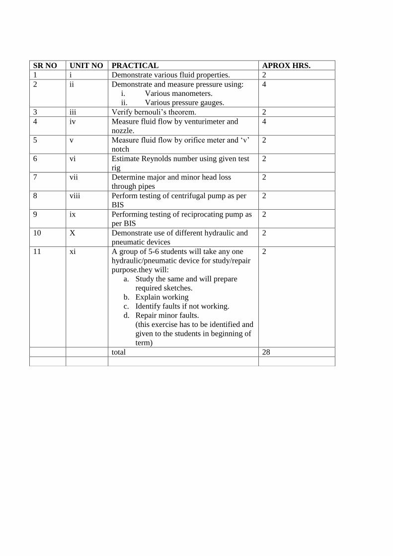
SR NO UNIT NO PRACTICAL APROX HRS.
1 i Demonstrate various fluid properties. 2
2 ii Demonstrate and measure pressure using:
i. Various manometers.
ii. Various pressure gauges.
4
3 iii Verify bernouli‟s theorem. 2
4 iv Measure fluid flow by venturimeter and
nozzle.
4
5 v Measure fluid flow by orifice meter and „v‟
notch
2
6 vi Estimate Reynolds number using given test
rig
2
7 vii Determine major and minor head loss
through pipes
2
8 viii Perform testing of centrifugal pump as per
BIS
2
9 ix Performing testing of reciprocating pump as
per BIS
2
10 X Demonstrate use of different hydraulic and
pneumatic devices
2
11 xi A group of 5-6 students will take any one
hydraulic/pneumatic device for study/repair
purpose.they will:
a. Study the same and will prepare
required sketches.
b. Explain working
c. Identify faults if not working.
d. Repair minor faults.
(this exercise has to be identified and
given to the students in beginning of
term)
2
total 28
EXPERIMENT NO 1
AIM:- Demonstrate the fluid properties.
INTRODUCTION:-
Fluid mechanics is a branch of science which deals with behavior of fluid at rest or in
motion. Thus this science deals with static and dynamic kinematics.
PROPERTIES OF FLUID:-
DENSITY OR MASS DENSITY.
Density or mass density of fluid is defined as ratio of mass of fluid to its volume. Thus mass per unit
volume is called as density. The unit of mass density in SI unit is Kg per cubic meter.
P= Mass of fluid
Volume of fluid
The value of density of water is 1000Kg/m3
SPECIFIC WEIGHT OR WEIGHT DENSITY.
Specific weight is a ratio weight of fluid per volume. Thus weight per unit volume is called Specific
Weight or Weight Density. It is denoted by symbol w.
W=p*g
Value of Specific Weight or Weight Density is 9.81*1000 Newton/m3 in si system.
SPECIFIC VOLUME:
Specific volume is defined as volume per unit mass.
It is expressed as m3/kg
SPECIFIC GRAVITY:-
Specific gravity is defined as ratio of weight density of a fluid to the weight density of a standard
fluid. For liquid standard fluid is water and for gas it is air.
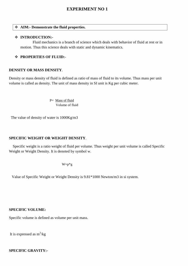
VISCOSITY:-
Viscocity is defined as property of fluid wich offers resistance to the movement of one layer of fluid
over other adjacent layer of the fluid.
Mathematically,
Ʈ= µ du/dy
The unit of viscosity are NS/m2
KINEMATIC VISCOSITY:
It is defined as ratio of dynamic viscosity and density of fluid. Denoted by greek letter V.
V=Viscosity/density
]
EXPERIMENT NO:-2
AIM: To Determine and measure pressure using various manometers and various
pressure gauge.
MEASUREMENT AND PRESSURE:
The pressure of a fluid is measured by the following device:
1) Manometers 2) Mechanical gauges
1. Manometers: Manometers are defined as the device used for measuring the pressure at a
point in a fluid by balancing the column of fluid by the same or another column of the fluid.
They are classified as:
[a] Simple manometers, [b] Differential Manometers.
2. Mechanical Gauges: Mechanical Gauges are the defined as the devices used for measuring
the pressure by balancing the fluid column by the spring or dead weight. The commonly used
mechanical pressure gauges are:
[A] bourdon tube pressure gauge:
[B] Diaphragm pressure gauge:
[C] Dead-weigth pressure gauge:
Simple Manometers:
A simple manometer consists of a glass tube having one of its ends connected to a point where
pressure is to be measured and other end remains open to atmosphere. Common types of simple
manometers are
1. Piezometer
2. U-tube manometer.
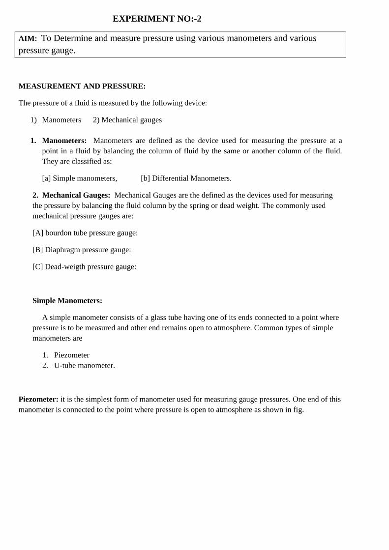
Piezometer: it is the simplest form of manometer used for measuring gauge pressures. One end of this
manometer is connected to the point where pressure is open to atmosphere as shown in fig.
U-tube manometer: it consists of glass tube bent in U-shape, one end of which is connected to a
point at which pressure is to be measured and other end remains open to the atmosphere as shown
in fig-b.
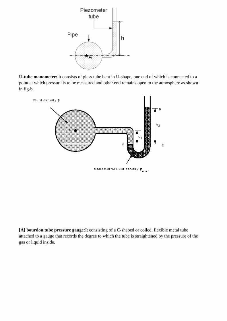
[A] bourdon tube pressure gauge:It consisting of a C-shaped or coiled, flexible metal tube
attached to a gauge that records the degree to which the tube is straightened by the pressure of the
gas or liquid inside.
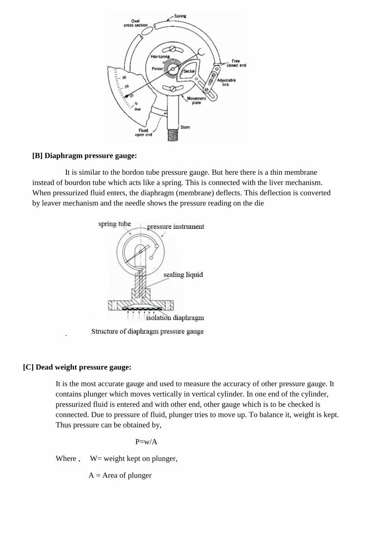
[B] Diaphragm pressure gauge:
It is similar to the bordon tube pressure gauge. But here there is a thin membrane
instead of bourdon tube which acts like a spring. This is connected with the liver mechanism.
When pressurized fluid enters, the diaphragm (membrane) deflects. This deflection is converted
by leaver mechanism and the needle shows the pressure reading on the die
.
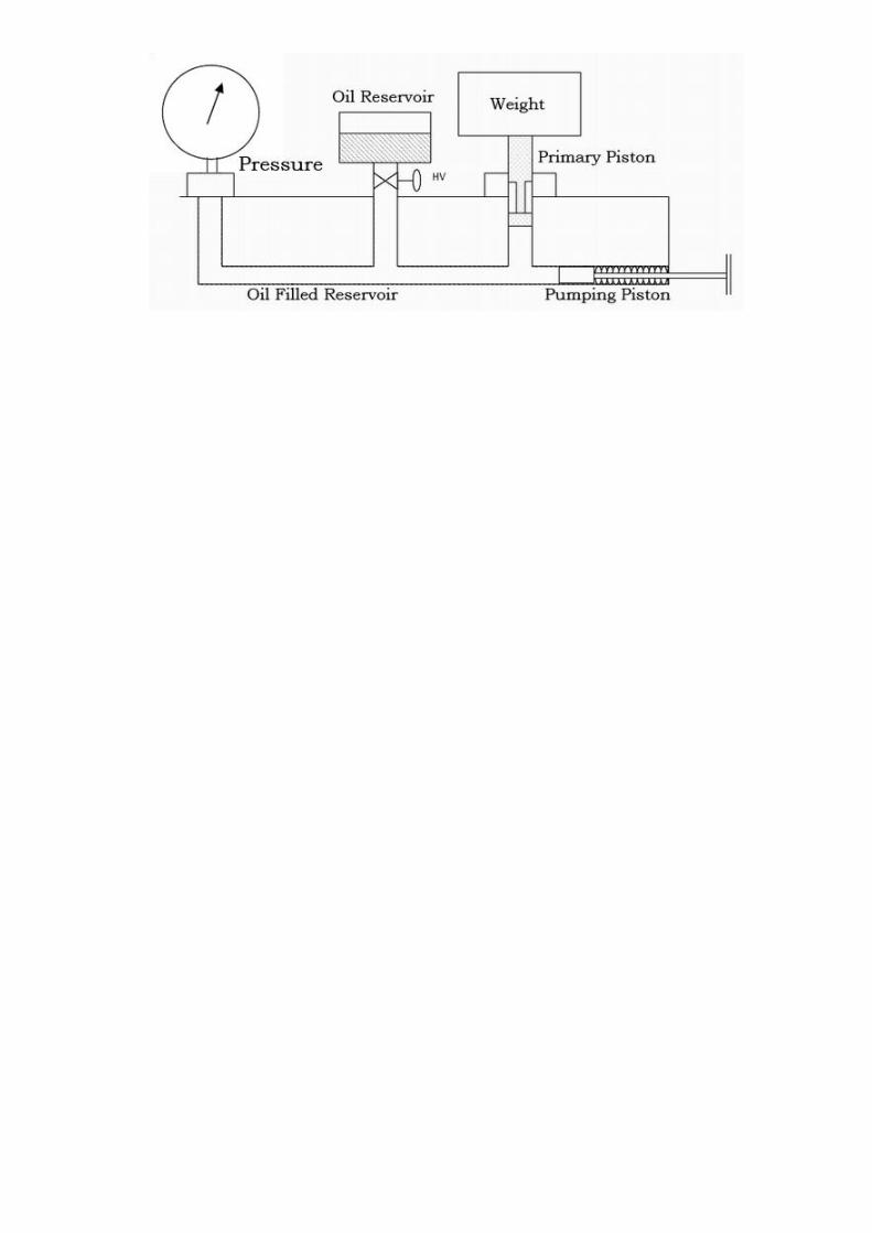
[C] Dead weight pressure gauge:
It is the most accurate gauge and used to measure the accuracy of other pressure gauge. It
contains plunger which moves vertically in vertical cylinder. In one end of the cylinder,
pressurized fluid is entered and with other end, other gauge which is to be checked is
connected. Due to pressure of fluid, plunger tries to move up. To balance it, weight is kept.
Thus pressure can be obtained by,
P=w/A
Where , W= weight kept on plunger,
A = Area of plunger
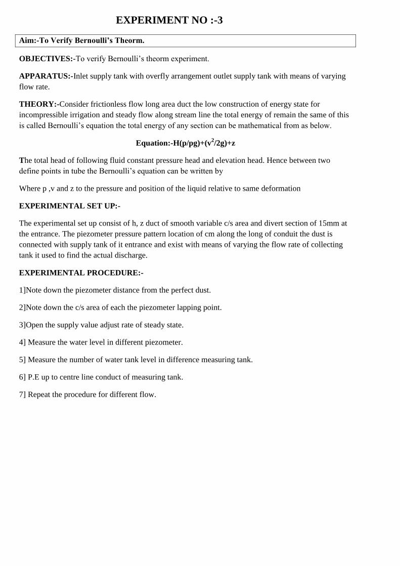
EXPERIMENT NO :-3
Aim:-To Verify Bernoulli‟s Theorm.
OBJECTIVES:-To verify Bernoulli‟s theorm experiment.
APPARATUS:-Inlet supply tank with overfly arrangement outlet supply tank with means of varying
flow rate.
THEORY:-Consider frictionless flow long area duct the low construction of energy state for
incompressible irrigation and steady flow along stream line the total energy of remain the same of this
is called Bernoulli‟s equation the total energy of any section can be mathematical from as below.
Equation:-H(p/pg)+(v2/2g)+z
The total head of following fluid constant pressure head and elevation head. Hence between two
define points in tube the Bernoulli‟s equation can be written by
Where p ,v and z to the pressure and position of the liquid relative to same deformation
EXPERIMENTAL SET UP:-
The experimental set up consist of h, z duct of smooth variable c/s area and divert section of 15mm at
the entrance. The piezometer pressure pattern location of cm along the long of conduit the dust is
connected with supply tank of it entrance and exist with means of varying the flow rate of collecting
tank it used to find the actual discharge.
EXPERIMENTAL PROCEDURE:-
1]Note down the piezometer distance from the perfect dust.
2]Note down the c/s area of each the piezometer lapping point.
3]Open the supply value adjust rate of steady state.
4] Measure the water level in different piezometer.
5] Measure the number of water tank level in difference measuring tank.
6] P.E up to centre line conduct of measuring tank.
7] Repeat the procedure for different flow.
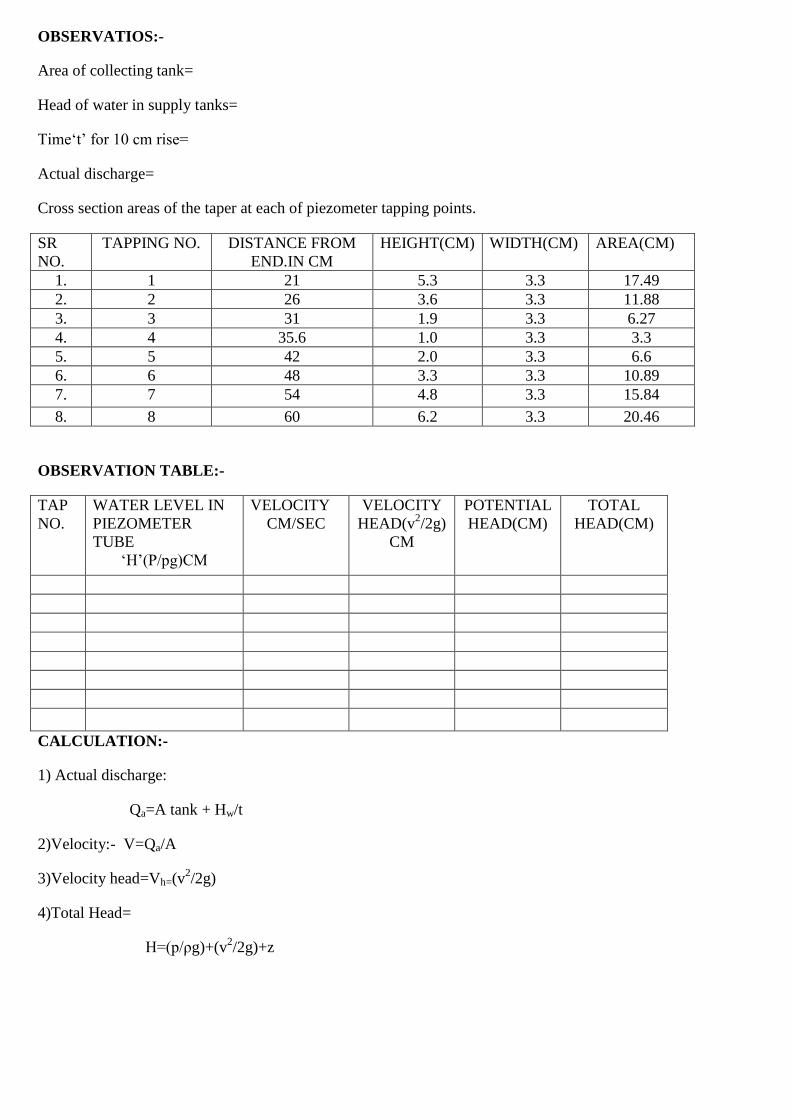
OBSERVATIOS:-
Area of collecting tank=
Head of water in supply tanks=
Time„t‟ for 10 cm rise=
Actual discharge=
Cross section areas of the taper at each of piezometer tapping points.
SR
NO.
TAPPING NO. DISTANCE FROM
END.IN CM
HEIGHT(CM) WIDTH(CM) AREA(CM)
1. 1 21 5.3 3.3 17.49
2. 2 26 3.6 3.3 11.88
3. 3 31 1.9 3.3 6.27
4. 4 35.6 1.0 3.3 3.3
5. 5 42 2.0 3.3 6.6
6. 6 48 3.3 3.3 10.89
7. 7 54 4.8 3.3 15.84
8. 8 60 6.2 3.3 20.46
OBSERVATION TABLE:-
TAP
NO.
WATER LEVEL IN
PIEZOMETER
TUBE
„H‟(P/pg)CM
VELOCITY
CM/SEC
VELOCITY
HEAD(v2/2g)
CM
POTENTIAL
HEAD(CM)
TOTAL
HEAD(CM)
CALCULATION:-
1) Actual discharge:
Qa=A tank + Hw/t
2)Velocity:- V=Qa/A
3)Velocity head=Vh=(v2/2g)
4)Total Head=
H=(p/ρg)+(v2/2g)+z
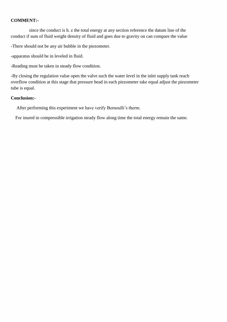
COMMENT:-
since the conduct is h. z the total energy at any section reference the datum line of the
conduct if sum of fluid weight density of fluid and goes due to gravity on can compare the value
-There should not be any air bubble in the piezometer.
-apparatus should be in leveled in fluid.
-Reading must be taken in steady flow condition.
-By closing the regulation value open the valve such the water level in the inlet supply tank reach
overflow condition at this stage that pressure head in each piezometer take equal adjust the piezometer
tube is equal.
Conclusion:-
After performing this experiment we have verify Bernoulli‟s therm.
For inured in compressible irrigation steady flow along time the total energy remain the same.
EXPERIMENT NO:-4(A)
Aim:- Flow Measurment By Venturimeter And Nozzle.
Objectives:-
To calibrate the Venturimeter i.e. to prepare a graph to find out discharge when
difference in limbs of manometer is known.
To determine the co-efficient of discharge for a given Venturimeter.
PRACTICAL SIGNIFICANCE:-
The practical application of Bernoulli‟s theorem is found in this apparatus.It is also
used for actual flow(discharge)measurements of fluids.
PREREQUISITE THEORATICAL BACKGROUND:-
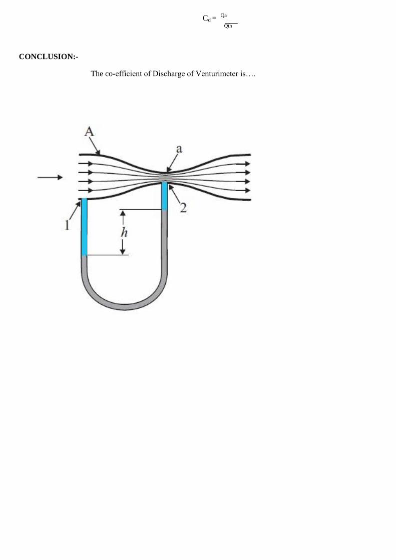
The Venturimeter is an apparatus for finding out the discharge of a liquid flowing in a
pipe. A Venturimeter, in its simplest from consist of the following three parts.
Convergent Cone
Throat
Divergent Cone
1)Convergent Cone:-It is a short pipe which pipe converges from a diameter from a
diameter “d1” to a smaller diameter “d2” it is also known as inlet of the Venturimeter.
The slope of the converging sides is in between 1 in 4 to 1 in 5.
2)Throat:-It is a small portion of circular pipe, in which diameter d2 is kept constant.
3)Divergent Cone:-It is a pipe, which diverges from a diameter d2 to a large diameter
d1.The length divergent cone be is about 3 to 4 times more than convergent cone.
The is accelerated in convergent cone, when flowing through the Venturimeter
As a result of acceleration, the velocity at throat increases and pressure decreses,if the
pressure head at the throat falls below 2.5 meters of water then there will be a tendency
of separation of the liquid flow. To avoid this, there is a ratio of the
Throat to the pipe.i.e. d2/d1. The most suitable value of this ratio is 1/3 to1/2.
The liquid while flowing through the Venturimeter is related in Divergent
cone, so velocity decreases and increases hence there is possibility for the stream of
liquid to break away from the walls of the meter due to boundary layer effects. To
avoid this and to reduce friction losses, the Divergent cone. The theoretical flow of
liquid through the Venturimeter is as follows.
Qth= A1 + A2 + (√2gh)
√(A1
2-A2
2)
WHERE,
Qth =Theoretical discharge
A1 = Area of inlet
A2 = Area of throat
H =Different of pressure head of water between inlet and
Outlet
Cd =Co-efficient of Discharge
PRECAUTION:-
1) There should not be air-bubbles in U-tube mercury
Manometer.
2) When taking the reading-h, U-tube mercury column
Should be stable.
PROCEDURE:-
1) Find out the c/s area of the measuring tank.
2) Open the valve at upstream end of the measuring tank.
3) Wait till mercury columns of manometer becomes stable.
4) Record the manometer reading.
5) Measure time required for 10 cm rise in collecting tank.
6) Repeat steps 2 to 5 by opening the valve to an increasing degree and record the
observation in the following format.
OBSERVATION:-
1) Diameter of pipe (d1) =
2) Diameter of throat (d2) =
3) Area of c/s of pipe (A1) =
4) Area of c/s of throat (a2) =
5) Area of measuring tank A =
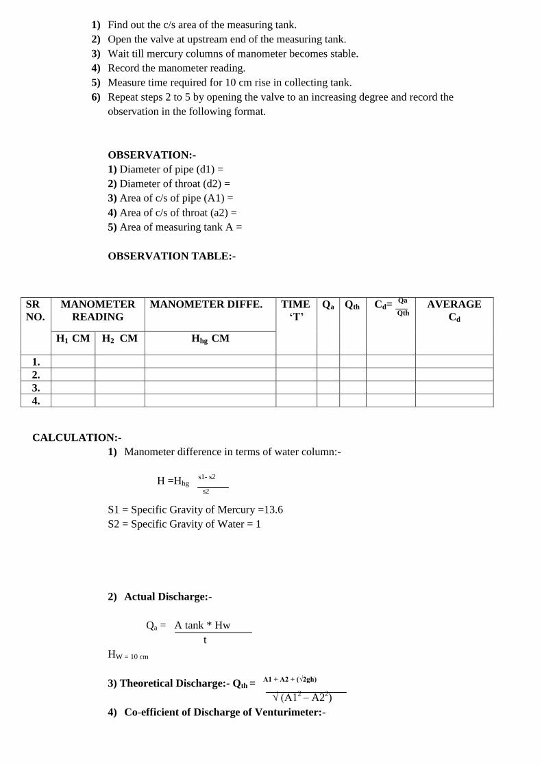
OBSERVATION TABLE:-
CALCULATION:-
1) Manometer difference in terms of water column:-
H =Hhg s1- s2
s2
S1 = Specific Gravity of Mercury =13.6
S2 = Specific Gravity of Water = 1
2) Actual Discharge:-
Qa = A tank * Hw
t
HW = 10 cm
3) Theoretical Discharge:- Qth = A1 + A2 + (√2gh)
√ (A1
2 – A2
2)
4) Co-efficient of Discharge of Venturimeter:-
SR
NO.
MANOMETER
READING
MANOMETER DIFFE. TIME
„T‟
Qa Qth Cd= Qa
Qth
AVERAGE
Cd
H1 CM H2 CM Hhg CM
1.
2.
3.
4.
Cd = Qa
Qth
CONCLUSION:-
The co-efficient of Discharge of Venturimeter is….
EXPERIMENT NO:-4-B
AIM:- To Study Fluid Flow By Nozzle .
OBJECTIVE:-To Determine the co-efficient of velocity of co-efficient construction of nozzles. A
nozzle is type of orifice with rounded edges on upstream side.
APPARATUS:-Supply tank with overflow arrangement of fitting of orifice installed in the vertical
plan of the tank side scale apparatus with book gauge a sat of orifice.
EXPERIMENTAL SET UP:-
The experimental set up consist of a supply with overflow arrange and gauge level measurement at
the tank. There are also for fixing different orifice installed in the vertical plane at the tan side
arrangement is made such that water passage through this method opening water comes out the
opening in the from get.
A horizontal scale on which is mounted a vertical scale with a hook gauge is attached to the supply
tank is hook. Gauge is attached to as well vertically in direction its cross pending movement can be
read on horizontal and vertical solve respect a tank as used of water through the yet.
PROCEDURE:-
1)Note down the lead of centre of after as are of collecting tank and supply tank.
2) Attach or orifice and note down its diameter.
3) Measure the lead at centre level of orifice to as bottom.
4)Locate the tip of hook gauge between consist and tank of the inter h. z & v c scale respectively.
5)Measure discharge of water following through the orifice by collecting tank water in measuring tank
for time period.
OBSERVATION:-
1. Diameter of pipe (d1) =
2. Diameter of Nozzle (d2) =
3. Area of c/s of pipe (A1) =
4. Area of c/s of orifice (a2) =
5. Area of measuring tank A =
OBSERVATION TABLE:-
CALCULATION:-
1)Manometer difference in terms of water column:-
H = Hhg s1 – s2
S2
S1 =Specific gravity of Mercury = 13.6
S2 = Specific gravity of water = 1
2) Actual Discharge:-
Qa = A tank *
Hw
t
HW = 1O cm
3)Theoretical Discharge:-
Qth =
A
1 + A
2 + (√2gh
)
√ (A1
2 – A2
2)
5) Co-efficient of Discharge of Venturimeter:-
Cd = Qa
Q
th
APPLICATION:-
It is very useful an may hydraulic device like.
1) Hydraulic press
2) Hydraulic crane
3) Hydraulic lift
CONCLUSION:-The co-efficient of discharge of nozzle is =………………………….
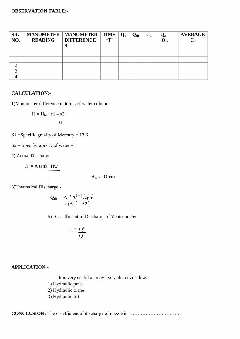
SR.
NO.
MANOMETER
READING
MANOMETER
DIFFERENCE
S
TIME
„T‟
Qa Qth Cd = Qa
Qth
AVERAGE
Cd
1.
2.
3.
4.
\
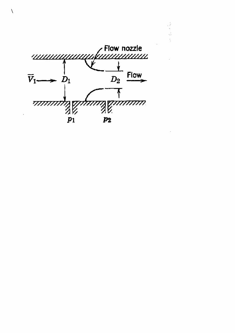
EXPERIMENT NO:- 5(A)
AIM: To measure fluid flow by orifice meter.
OBJECTIVE: To established orifice meter by establishing the relationship between flow rate and
pressure difference and to find its co-efficient of dishcharge.
APPARATUS: shape edge circular orifice installed in a pipeline-tube, monometer, supply tank and
measure tank, stop watch.
CHEMICAL: water, mercury
THEORY: an orifice meter in available head meter in which area of flow is discharge by allowing the
flow through a small constriction there by covering the pressure energy. The pressure differential thus
creased is measure by a pressure measuring device. Orifice is a simple device to measure the flow in a
pipe by reducing the flow passage in one section. The pressure difference between 2 sections is
created. The measurement of pressure difference between 2 sections enables us to determine the
discharge, which is taking place in the pipe. Since the diameter of the passage at the orifice meter is
less than that of the pipe, the flowing stream converges to a minimum cross-section known as vena-
contracta. As the fluid flows through it the velocity of the flow of fluid reaches maximum value & the
pressure becomes minimum. A pressure tap is provided at this section. Another pressure tap is
provided at a distance of 0.9 to 01.1 times the diameter of pipe from orifice plate where the pressure is
maximum (velocity is equal to velocity of flow in the pipe). So connecting a manometer to these
pressure taps we get the pressure differences.. This pressure difference is resulted to voltmeter flow
rate discharge. Through the pipe by following equation.
Where A= area of orifice
A1=area of pipe
H=difference of head
G= acceleration due to gravity.
PROCEDURE:
(i) Diameter of pipe and orifice are noted down.
(ii) Air in the manometer pipe is removed after allowing war to pass through the pipe.
(iii) The inlet and outlet valves are brought to required position.
(iv) For a constant discharge the readings of the manometer are taken down.
(v) Collecting tank readings are taken down.
(vi) The above procedure is repeated for different values of discharge.
(vii) The graph of Qact V/s H is plotted value of Cd is computed.
OBSERVATION:-
1) Diameter of pipe (d) =
2) Diameter of orifice =
3) Cross section area of pipe =
4) Cross section area of orifice =
5) Area of collecting tank =
OBSERVATION TABLE:-
SR NO MANOMETER
READING
MANOMETER
DIFFERENCES
TIME
T
Qa Qth Cd=Qa/Qth Avg
Cd
H1 cm H2 cm Hhg cm
CALCULATION:-
1) Manometer difference in terms of water column:-
H= Hhg x (S1-S2)/S3
S1= specific gravity of mercury =13.6
S2= specific gravity of water =1
2) Actual discharge :-
Qa = (Atank X Hw)/ t
3) Theoretical discharge :-
Qth = A1 x A2 x √2gh
√(A12 – A2
2)
4) Co- efficient of discharge of venturimeter :-
Cd = Qa/Qth
CONCLUSION:- we can perform this practical and convert that orifice meter is device which is used
to measure how rate at fluid through a pipe by converting the pressure energy of fluid in to kinetic
energy.
Also determine co-efficient of discharge for a given orifice mete
EXPERIMENT NO:-5 (B)
AIM: - To measure fluid flow by v-notch.
OBJECTIVES:- to calibrate v-notch and to find co-efficient of discharge.
APPARATUS: Triangular notch, hook gauge, stop watch etc.
THEORY: A notch may be defined as a sharp edged obstruction over which flow of a liquid occurs.
The sheet of water discharged by a notch is called vein. Notches are used for measuring the flow of
water from a reservoir and are generally rectangular, trapezoidal or triangular in shape. The most
common shape is triangular, since it has the advantage of greater accuracy at reduced flow rates
compared with other shapes. The coefficient of contraction will be constant for all heads. A triangular
notch is called V-notch.
PROCEDURE:
1. Fix the notch under test at the end of approach channel in a vertical plane with the sharp-edge on the
upstream side.
2. Fill the channel with water up to the crust level and note the initial reading „h‟ on the height gauge.
3. Adjust the flow control valve to give the maximum possible discharge without flooding the notch.
Note the final height gauge readings given the head over the notch i.e. H.
4. Collect the water discharging from the notch in a measuring tank of known dimensions and measure
the rise of water level „h‟ in the measuring tank for certain period of time.
5. Conditions are allowed to steady state before the head and rise of water level are recorded.
6. Lower and water level in the approach channel in stages by adjusting the flow control valve and
record the series of the readings h2 and „h‟ at each stage.
OBSERVATION:-
1. For v-notch, angle =60o
2. Lease count of height gauge=0.01
3. Area of measuring gauge Atank=
OBSERVATION TABLE:-
SR
NO
HEAD OF NOTCH
TIME
T
Qa Qth Cd=Qa/Qth Avg
Cd
H1
cm
H2
cm
Hhg= H2-H1 cm
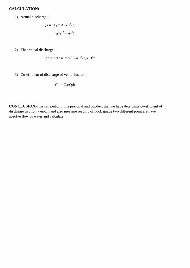
CALCULATION:-
1) Actual discharge :-
Qa = A1 x A2 x √2gh
√(A12 – A2
2)
2) Theoretical discharge:-
Qth =(8/15)x tan(θ/2)x √2g x H5/2
.
3) Co-efficient of discharge of venturimeter :-
Cd = Qa/Qth
CONCLUSION:- we can perform this practical and conduct that we have determine co-efficient of
discharge two for v-notch and also measure reading of hook guage two different point are have
absolve flow of water and calculate.
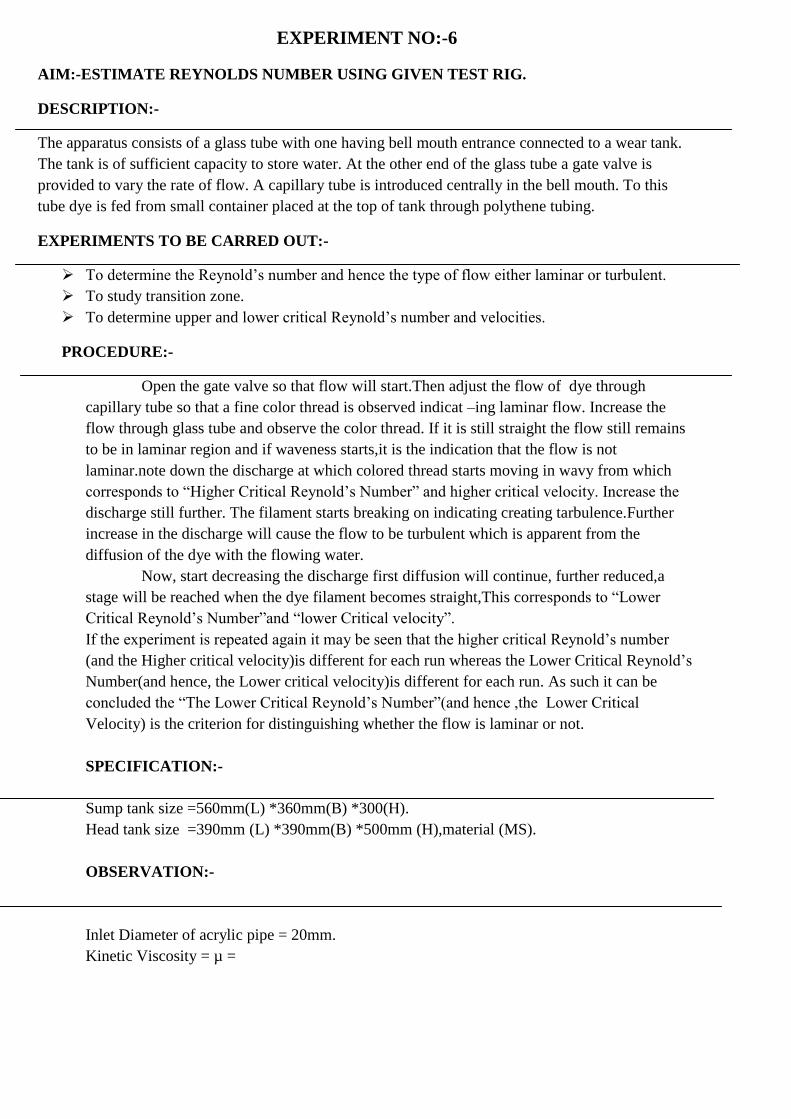
EXPERIMENT NO:-6
AIM:-ESTIMATE REYNOLDS NUMBER USING GIVEN TEST RIG.
DESCRIPTION:-
The apparatus consists of a glass tube with one having bell mouth entrance connected to a wear tank.
The tank is of sufficient capacity to store water. At the other end of the glass tube a gate valve is
provided to vary the rate of flow. A capillary tube is introduced centrally in the bell mouth. To this
tube dye is fed from small container placed at the top of tank through polythene tubing.
EXPERIMENTS TO BE CARRED OUT:-
To determine the Reynold‟s number and hence the type of flow either laminar or turbulent.
To study transition zone.
To determine upper and lower critical Reynold‟s number and velocities.
PROCEDURE:-
Open the gate valve so that flow will start.Then adjust the flow of dye through
capillary tube so that a fine color thread is observed indicat –ing laminar flow. Increase the
flow through glass tube and observe the color thread. If it is still straight the flow still remains
to be in laminar region and if waveness starts,it is the indication that the flow is not
laminar.note down the discharge at which colored thread starts moving in wavy from which
corresponds to “Higher Critical Reynold‟s Number” and higher critical velocity. Increase the
discharge still further. The filament starts breaking on indicating creating tarbulence.Further
increase in the discharge will cause the flow to be turbulent which is apparent from the
diffusion of the dye with the flowing water.
Now, start decreasing the discharge first diffusion will continue, further reduced,a
stage will be reached when the dye filament becomes straight,This corresponds to “Lower
Critical Reynold‟s Number”and “lower Critical velocity”.
If the experiment is repeated again it may be seen that the higher critical Reynold‟s number
(and the Higher critical velocity)is different for each run whereas the Lower Critical Reynold‟s
Number(and hence, the Lower critical velocity)is different for each run. As such it can be
concluded the “The Lower Critical Reynold‟s Number”(and hence ,the Lower Critical
Velocity) is the criterion for distinguishing whether the flow is laminar or not.
SPECIFICATION:-
Sump tank size =560mm(L) *360mm(B) *300(H).
Head tank size =390mm (L) *390mm(B) *500mm (H),material (MS).
OBSERVATION:-
Inlet Diameter of acrylic pipe = 20mm.
Kinetic Viscosity = µ =
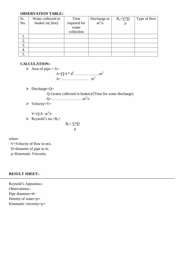
OBSERVATION TABLE:-
Sr.
No.
Water collected in
beaker in( litre)
Time
required for
water
collection
Discharge in
m3/s
Re=V*D
µ
Type of flow
1.
2.
3.
4.
5.
CALCULATION:-
Area of pipe = A=
A=∏/4 * d2
………………..m2
A= ………………… m2
Discharge=Q=
Q=(water collected in beaker)/(Time for water discharge)
Q=…………………….m3/s
Velocity=V=
V=Q/A m3/s
Reynold‟s no.=Re=
Re= V*D
µ
where
V=Velocity of flow in m/s.
D=diameter of pipe in m.
µ=Kinematic Viscosity
RESULT SHEET:-
Reynold‟s Apparatus:-
Observations:-
Pipe diameter=d=
Density of water=p=
Kinematic viscosity=µ=
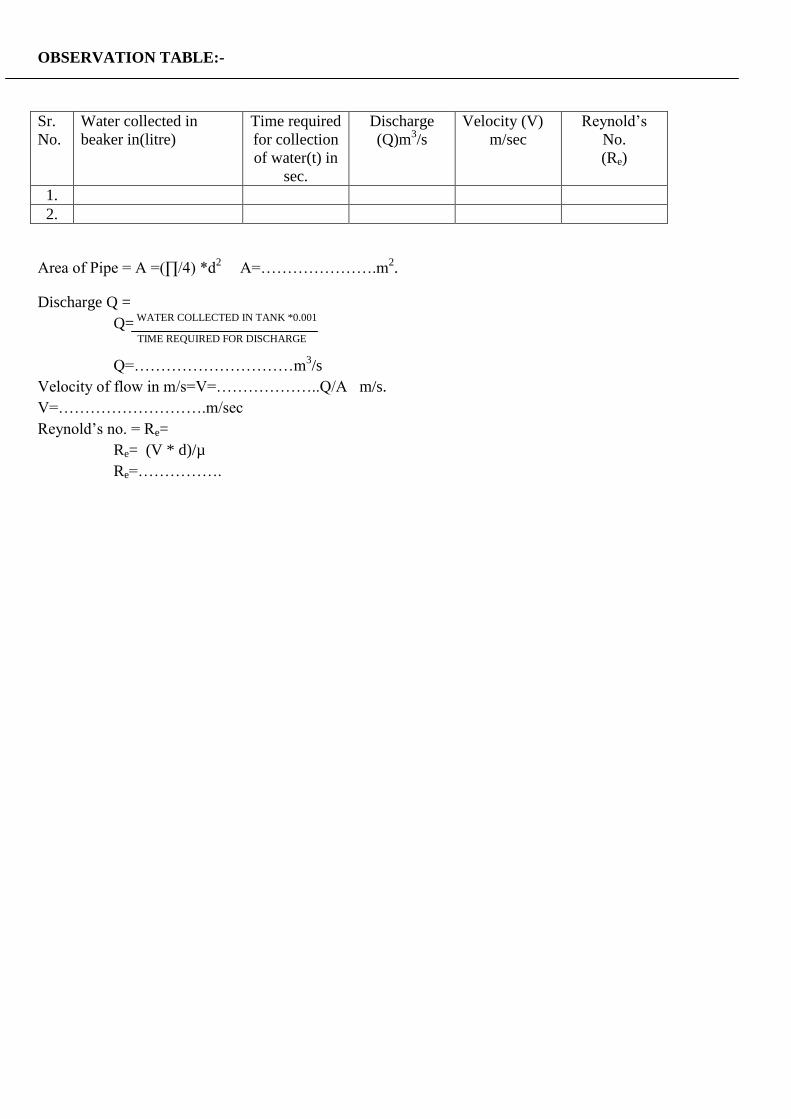
OBSERVATION TABLE:-
Sr.
No.
Water collected in
beaker in(litre)
Time required
for collection
of water(t) in
sec.
Discharge
(Q)m3/s
Velocity (V)
m/sec
Reynold‟s
No.
(Re)
1.
2.
Area of Pipe = A =(∏/4) *d2
A=………………….m2.
Discharge Q =
Q= WATER COLLECTED IN TANK *0.001
TIME REQUIRED FOR DISCHARGE
Q=…………………………m3/s
Velocity of flow in m/s=V=………………..Q/A m/s.
V=……………………….m/sec
Reynold‟s no. = Re=
Re= (V * d)/µ
Re=…………….
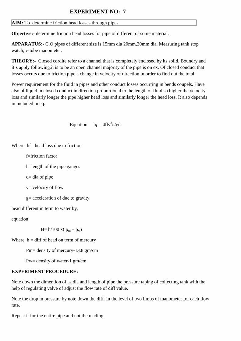
EXPERIMENT NO: 7
AIM: To determine friction head losses through pipes .
Objective:- determine friction head losses for pipe of different of some material.
APPARATUS:- C.O pipes of different size is 15mm dia 20mm,30mm dia. Measuring tank stop
watch, v-tube manometer.
THEORY:- Closed cordite refer to a channel that is completely enclosed by its solid. Boundry and
it‟s apply following.it is to be an open channel majority of the pipe is on ex. Of closed conduct that
losses occurs due to friction pipe a change in velocity of direction in order to find out the total.
Power requirement for the fluid in pipes and other conduct losses occurring in bends coupels. Have
also of liquid in closed conduct in direction proportional to the length of fluid so higher the velocity
loss and similarly longer the pipe higher head loss and similarly longer the head loss. It also depends
in included in eq.
Equation hf = 4flv2/2gd
Where hf= head loss due to friction
f=friction factor
l= length of the pipe gauges
d= dia of pipe
v= velocity of flow
g= acceleration of due to gravity
head different in term to water by,
equation
H= h/100 x( pm – pw)
Where, h = diff of head on term of mercury
Pm= density of mercury-13.8 gm/cm
Pw= density of water-1 gm/cm
EXPERIMENT PROCEDURE:
Note down the dimention of as dia and length of pipe the pressure taping of collecting tank with the
help of regulating valve of adjust the flow rate of diff value.
Note the drop in pressure by note down the diff. In the level of two limbs of manometer for each flow
rate.
Repeat it for the entire pipe and not the reading.
OBSERVATION:-
Diameter of pipe d1 =
Length of pipe L=
Area of measuring tank At =
OBSERVATION TABLE:-
SAMPLE CALCULATION:-
1) Discharge (Q) Qa = (Atank * Hw)/t
2) Friction head loss in m of water:-
Hf = ( SAg – Sw/Sw) * Hhg
3) Velocity(v):-
V= Qa/A
4) Co-efficient of pipe (f):-
Equation hf = 4flv2/2gd
CONCLUSION :-
Closed conduct to channel that it is completely enclosed by its solid boundary is fully that an
open change in velocity direction head loss. Liquid in closed that head loss.
Sr
no
FRICTIONAL
HEAD IN mm of
hg
FRICTIONAL
HEAD IN mm of
hg
FRICTIO
NAL
HEAD IN
mm OF
WATER
TIME
“t”
FOR 10
cm
RISE
(SEC)
DISCHARGE
‟Q‟m3/sec
VELOCIY
m/sec
FRICTION
FACTOR
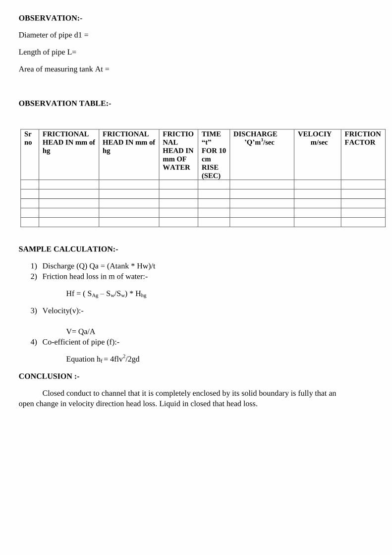
EXPERIMENT NO :-8
AIM:- to check the performance of given centrifugal pump.
APPARATUS:- centrifugal pump, D.C motor, rpm meter, vaccum gauge, pressure gauge, energy
meter, sump tank and measuring tank.
OBJECTIVES:- to determine the power consumption, output power of pump and pump efficiency.
PRACTICAL SIGNIFICANCE:-
After performing this practical you will be able to identify the function of pumps and its
basic mechanical elements converting the electrical energy into mechanical energy through motor
which is coupled with the pump and the mechanical energy gained by the pump.
THEORITICAL BACKGROUND:-
Transport of fluid through close conduit is a common feature in chemical industries. It
may be necessary to move a fluid against gravity force i.e. into pressure vessel, or pump it out freom a
vessel under vacuum as in case of evaporators. In all these cases, there will be additional losses of
energy due to friction as the liquid flows through conduits, fitting and valves. To ensure fluid
movement, energy has to be supplied to fluid from an external source. The centrifugal pump are the
most wide used in chemical industries.
The capacity of the pump is define as the volume of the fluid handled per unit time. For
incompressible fluid it is given in litter per minute. For compressible fluids, the capacity is given at the
inlet temperature and pressure of fluid.
The total head is the energy is the added by the pump to unit mass of the following stream.
Total head = P2 - P1 + v21 - v1
2 + (Z2 – Z1)
ρg 2g
where point 1 is taken as any point before pump on the suction line point 2 is any point on the delivery
line.
Theoretical energy Eth = ρgQH
Efficiency is the ratio of actual energy measured by watt meter to the theoretical energy
calculated from the equation.
PRECAUTION:-
1. Initially measuring tank must be empty.
2. Energy meter must be know for the rotations per KWh
3. Proming must be done before starting pump.
PROCEDURE:-
1. Prime the C.F. pump
2. Open delivery valve and start the C.F pump
3. Measure time required for 10 cm rise in, collecting tank
4. Record the pressure by the pressure gauge and vacuum gauge.
5. Record energy meter reading for one min.
6. Repeat steps 3 to 5 different closing of the delivery cock.
OBSERVATION TABLE:-
1. Measuring tank area=
2. Density of water =
OBSERVATION TABLE:-
Sr no Position of
Delivery
clock
Pressure
gauge
reading
(Kg/m2)
Vacuum
gauge
reading
mm of Hg
Time
„t‟ for
10 cm
Rise
sec
Energy meter
reading(E) watt
Actual
discharge
Total
Head
H
(meter
of
watt)
Initial
(E0)
watt
Final
(E)
watt
Diff.
watt
CALCULATION:
1. Actual Discharge:
Qa = (Atank x Hw)/t
2. Total head developed:
H = 10 x ( pressure gauge + Vacuum gauge/760)
3. Theoretical energy:
Eth = ρg QH
4. Actal energy:
Ea = (E-E0) x 1000 x 60
5. Efficiency :
D = Eth/Ea
CONCLUSION:-After performing this practical you will be able to identify the function of pumps
and its basic mechanical elements converting the electrical energy into mechanical energy through
motor which is coupled with the pump and the mechanical energy gained by the pump.
EXPERIMENT NO: 9
AIM: To perform test on reciprocating pump.
OBJECTIVES: To determine the co-efficient of discharge percentage slope efficiency and
reciprocating pump.
THEORY:-
Reciprocating pumps are positive pumps. Initialy a small quantity of liquid is taken into a
chamber and is physically displaced and forced out by with pressure by moving mechanical
element.The moving mechanical element may be a gear system rotating in the housing, or piston
moving in cylinder with the help of external power source.Thus,if the chamber is alternatively filled
by drawing in the liquid to be pumped and emptied by forcing it out, the liquid from the sump can be
raised to the required height.
EXPERIMENT PROCEDURE
- keep delivery valve plastically open start elastimeter.
- Measure the delivery pressure heat head.
-Measure the speed pump applies with tachometer.
- Note down time requires for 10cm length of water in measure tank the experiment for different
delivery valve.
SPECIFICATION:
Head =
Discharge =
Input power =
DATA:
- Diameter of piston
- Length of stoke
- Area of measuring tank
- Height difference between delivery guage
- Electric meter constant
- Speed
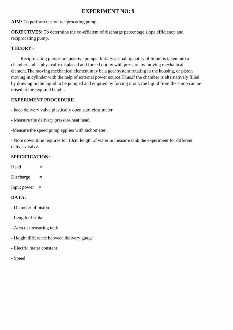
OBSERVATION:
1. Measure tank area (Atank)=
2. Density of water P =
OBSERVATION TABLE:
CALCULATION:
1. Theoritical capacity of pump:-
𝑄𝑡ℎ =2𝐿𝐴𝑁
60𝑚3/ sec
2. Total Head develop :-
H = hs + HD
H = 10 (pressure gauge + 𝑣𝑎𝑐𝑢𝑢𝑚𝑔𝑎𝑢𝑔𝑒
760 )
3. Power output :-
Pout = pg𝑄𝑡ℎH
4. Power=(E𝐸0)*1000*60
5. Efficiency:
D = Pout / Pin
CONCLUSION:
We are able to know that reciprocation pump is positive displacement. Pump which has a cylinder is
alternating discharge depend almost entry on the speed of pump.
Sr no Position of
Delivery
clock
Pressure
gauge
reading
(Kg/m2)
Vacuum
gauge
reading
mm of Hg
Time
„t‟ for
10 cm
Rise
sec
Energy meter
reading(E) watt
Actual
discharge
Total
Head
H
(meter
of
watt)
Initial
(E0)
watt
Final
(E)
watt
Diff.
watt
EXPERIMENT NO: 10
Aim: Demonstrate Use Of Different Hydraulic And Pneumatic Device
INTRODUTION: Student should write a report any one hydraulic device from listed below as
introducing by the faculty member different student can be assigned to write a different device.
WORKING PRINCIPAL: It used to increase the liquid pressure by utilised energy quantity of liquid
us low pressure that available from pump.
Hydraulic device like hydraulic produce & like need high pressure.
Hydraulic intensity is placed between pump& hydraulic device.
CONSTRUCTION: The hydraulic interfere consist of fixed ram is secreting by sliding inside a
fixed& inlet 7 outlet valve.
WORKING: Let us insert sliding ram at the bottom of its stroke the inlet existed valve on the while
the low pressure liquid from the fixed track most position its completely fill up with low pressure
head.
PIA=PZP
PZ=A/0 X PI
Where,
A= area of cylinder fixed
a= area of cylinder
PI=pressure intency low pressure liquid in fixed cylinder
PZ= pressure of high pressure liquid in sliding
APPLICATION: it is very useful in many hydraulic device like to
1. Hydraulic press
2. Hydraulic crain
3. Hydraulic lifted etc……
CONCLUSION: We can study with this practice &we inserted the constantly working & application
& awareness to know in which such reaction hydraulic device are utilised & where can used it.
Pneumatic devices
INTRODUCTION:
Should write a report on ant one pneumatic device instructed by faculty member
different student can be assingned to write report or different devices.
Pneumatic power drive system consist of double acting calculus cylinder apps of a ideas
accurate for vane motor like rotary actuations compressor failure to flow contra.
The compressed air as used in pneumatic power drive to system a compressed air compressed
by compressive enters. In both pipe through FRI unit which is consist of the filter release and lubricant
after that air in cylinder through direction central value.
When compressed air enters into cylinder as shown in fig. and there will be. A act ways stole for the
return enter of piston.
During return stoke. Air on other side at piston goes to atmosphere that‟s control value and
solenoid.
Basic requirement for a pneumatic system are,
Compressor
Pipe line
Air actuator
Application
CONCLUSION:-
WE CAN STUDY TO THIS PRACTICAL and after study we understand the
constant working and application accuracy to flow in which situation we can use device.
EXPERIMENT NO : 11
(this exercise has to be identified and given to the students in beginning of term)
AIM: A group of 5-6 students will take any one hydraulic/pneumatic device for study/repair
purpose.they will:
a. Study the same and will prepare required sketches.
b. Explain working
c. Identify faults if not working.
d. Repair minor fault

![Full page photo - Mahavir Swami Institute of Technology · ET'E( '-305 Microprocessor & M lcrocontl ollers ETF,L-3()5 Signals & stems Sensors & Transducers li]WC-405 Wireless ETF.L](https://img.pdfslide.net/doc/110x75/6072f6dba53c9b51013a74fc/full-page-photo-mahavir-swami-institute-of-ete-305-microprocessor-m.jpg)


![Bhagwan Mahavir Swami[1]](https://img.pdfslide.net/doc/110x75/552244c04a79595d5e8b4812/bhagwan-mahavir-swami1.jpg)