Embed Size (px)
Citation preview
1
Maher AttalOn behalf of
SESAME Team
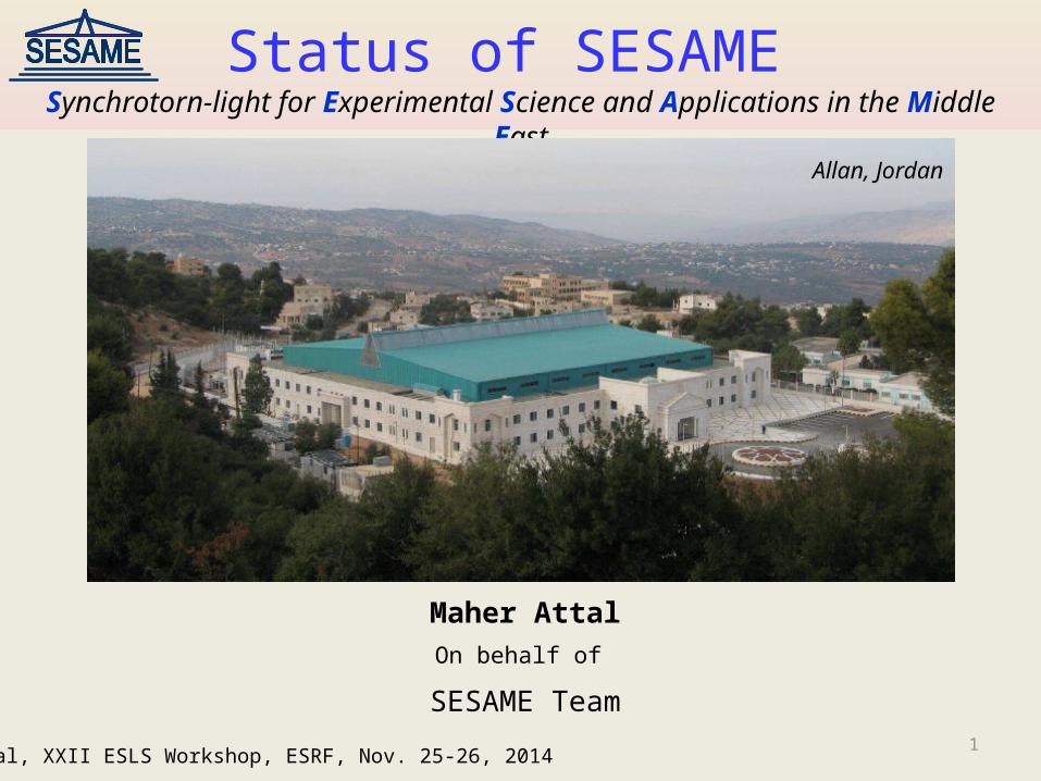
Status of SESAME Synchrotorn-light for Experimental Science and Applications in the Middle East
M. Attal, XXII ESLS Workshop, ESRF, Nov. 25-26, 2014
Allan, Jordan

2M. Attal, XXII ESLS Workshop, ESRF, Nov. 25-26, 2014
Introduction
SESAME is an interregional 3rd generation light source being constructed in Jordan (in Allan, 30km west of Amman) and expected to serve the user community in the Middle East region.
SESAME machine composes: BESSY I injector (22 MeV classical Microtron + 800 MeV Booster) completely new 2.5 GeV storage ring. mixture of donated ( by SLS, HZDR, LURE, Daresbury) and new beamlines.

3M. Attal, XXII ESLS Workshop, ESRF, Nov. 25-26, 2014
Microtron + TL1 Commissioning
Full energy beam at Microtron exit (~22MeV) Nov. 28, 2011.
Full energy beam at end of Microtron-Booster transfer line (~22MeV) March 27, 2012.
SESAME Microtron Main Parameters
Extractable energy 5.3-22.5MeVExtractable turns 10 – 42Energy gain / turn 535 keVEnergy spread(FWHM) 35keV Magnetic field 0.112TMicrowave frequency, power 3GHz, 2MWPulse duration 2sBeam power 400kW at 21MeVH-emittance 3.8 m.rad (100% of the beam @ 21MeV)V-emittance 12.8 µm.rad (100% of the beam @ 21MeV)
3 mm
4.4 mm

4
Booster Commissioning Results
Booster
Transfer line TL2
TL1 Microtron Main Booster parameters
Injection energy 20MeVExtraction energy 800MeVCircumference 38.4mH-emittance 300 nm.radV-emittance 30 nm.radMom. com. factor 0.18RF frequency 500MHzRF max. power 2kWOperation freq. 1HzInj. kicker pulse ~ 4.5µs
M. Attal, XXII ESLS Workshop, ESRF, Nov. 25-26, 2014

5
The first turn beam (July 15, 2014). No correctors are used.
Few turn beam (July 16, 2014). No correctors are used. using model values (QF= 2.83A, QD= -2.18A, Dipole= 24.96A) Varying injection angle. optimizing amplitude and timing of injection kicker kick.
Multi turn beam (thousands) (July 17, 2014).
Varying magnets current slightly from model values. Modifying slightly injection angle. 0.2A in Corr. 3 enhanced the transmission substantially.
Booster Commissioning Results
M. Attal, XXII ESLS Workshop, ESRF, Nov. 25-26, 2014

6
Characterizing the DC Mode
RF paramaters
Varying RF phase had no noticeable effect on the beam current in the Booster. The theoretical RF frequency 499.654MHz showed almost the best performance. Tune measurement
Horizontal tune was measured easily using the beam injection oscillations. Vertical tune was measured by injecting the beam with vertical angle (shaker is not ready yet). Three working points have been found as a result of scanning: 1- (2.22, 1.31), a working point mentioned in BESSY documents. 2- (2.22, 1.40) 3- (2.28, 1.47)
M. Attal, XXII ESLS Workshop, ESRF, Nov. 25-26, 2014

7
1- The point (2.22, 1.31) obtained for (QF = 2.67A, QD = 2.14A) (corresponding model values are QF = 2.83A, QD = 2.18A). It has low beam current transmission & low beam lifetime as shown by DCCT. DCCT signal
2- The point (2.22, 1.4) obtained for (QF = 2.68A, QD = 2.27A). It realizes better transmission with beam lifetime ~ 100ms.
Characterizing the DC Mode
M. Attal, XXII ESLS Workshop, ESRF, Nov. 25-26, 2014

8
Characterizing the DC Mode
3- The point (2.28, 1.47) for (QF = 2.77A, QD = 2.47A). It realizes good transmission with the best beam lifetime ~ 150ms.
Theoretical beam lifetime @20MeV is ~ 150ms if the Booster average pressure is 5e-7 mbar.
Betatron function measurement
Measure Qx versus kQF and kQD.
use the formula , N: number of family quadrupoles, Lq = 0.256m.
< x > = 4.65m @ QF (theoretical value is 5.3m) . < x > = 0.94m @ QD (theoretical value is 1.12m) .
M. Attal, XXII ESLS Workshop, ESRF, Nov. 25-26, 2014

9
Characterizing the DC Mode
Dispersion function measurement
Measure orbit position x for RF frequency fRF. BPM1 showed x = 2.3 mm for fRF = -100 kHz.
using the formula , and theoretical c = 0.18.
x = 2.06m (theoretical dispersion = 1.6m)
M. Attal, XXII ESLS Workshop, ESRF, Nov. 25-26, 2014
The fluctuating beam was always a prominent source of measurement error.

10
Energy Ramping Mode
Beam energy was ramped successfully to 800MeV (Sep. 17, 2014). Ibeam = 1.3 mA (~ 1.7% injection efficiency)
Injection was done at 23.9 ms delay in a semi-flat top region in the dipole current ramping curve.
M. Attal, XXII ESLS Workshop, ESRF, Nov. 25-26, 2014
0.00 200.00 400.00 600.00 800.00 1000.00 1200.000
200400600800
10001200
Dipole current ramp
time (ms)
Dipo
le cu
rren
t (A)
0.00 10.00 20.00 30.00 40.00 50.000
1020304050
Dipole current ramp
Time (ms)
Dipo
le cu
rren
t (A)
Injection moment
RF voltageDipole current
The ramping curve started with the working point (2.22, 1.4) .

11
Energy Ramping Mode
Ibeam = 4 mA (~ 5% injection efficiency) was achieved (Oct. 29, 2014). Another dipole current curve was used without a flat-top region (injection on the fly).
M. Attal, XXII ESLS Workshop, ESRF, Nov. 25-26, 2014
Injection moment
0 5 10 15 20 25 30 35 40 45 500
20406080
Dipole current
Time (ms)
Curr
ent (
A)
The RF voltage ramping curve started with 5kV and ended with 70 kV (injection voltage = 8kV).
RF voltage ramping curve
* Beam fluctuation due to instability in electrostatic injection septum.

12
Beam Images at Different Energies
The electron beam was imaged at different energies (during the ramping) using the added Visible Light Diagnostic beam line. The beam size was roughly measured over the ramping time.
100ms (~120MeV) 300ms (~440MeV) 500ms (~735MeV) 640ms (~800MeV)
M. Attal, XXII ESLS Workshop, ESRF, Nov. 25-26, 2014
100 150 200 250 300 350 400 450 500 550 6000
0.2
0.4
0.6
0.8
1
1.2
1.4
ramp time [ms]
horiz
onta
l bea
msiz
e rm
s [m
m]
100 150 200 250 300 350 400 450 500 550 6000
0.20.40.60.8
11.21.41.61.8
ramp time [ms]
verti
cal b
eam
size
rms [
mm
]

13
Booster Commissioning was done under Hard Conditions
M. Attal, XXII ESLS Workshop, ESRF, Nov. 25-26, 2014 13
December – April, 2014 November, 2014
The new roof is expected to be ready by Feb. 2015.
Tune measurement during ramping
Although no impact was seen on the acceleration efficiency, nevertheless the tune drift can be easily corrected.

14
Storage Ring Characteristics
Main 2.5 GeV Ring parameters: Simple DBA lattice (2 quadrupole families, 2 sextupole families) with dispersive sections. C = 133.2 m, Emitt. = 26 nm.rad. (Qx , Qy ) = (7.23, 6.19). Bending magnet: B0 = 1.455T, g = -2.79T/m. 16 straight sections (8x 4.4m + 8x 2.4m). Up to 25 beamlines ( 13 from dipoles + 12 from insertion devices).
x
y
x
Super-period.The ring is composed of 8 super-periods.
M. Attal, XXII ESLS Workshop, ESRF, Nov. 25-26, 2014

15
Storage Ring Status: Magnets
Storage ring magnets are constructed through CESSAMag project in the frame of SESAME-CERN/EU collaboration. Dipole (constructed by TESLA, UK) prototype is being magnetically measured at ALBA. All dipoles to be delivered by Sep. 2015.
Quadrupole prototype is being assembled (by Elytt-Spain, coils by STS-Turkey). First batch to be measured at CERN by March 2015.
Sextupole prototype (by CNE-Cyprus & HMC-3-Pakistan, coils by SEF-France) has been magnetically measured at CERN. First batch to be measured at CERN by March 2015.
M. Attal, XXII ESLS Workshop, ESRF, Nov. 25-26, 2014

16
Storage Ring Status: RF System
The 500MHz RF system is composed of 4 RF plants. Each plant composes:
- 120kW Elettra cavity (detuned up to ±2MHz).
Collaboration agreement was signed with Elettra. Delivery of 4 cavities foreseen by May 2016. - 80kW solid state amplifier(the 1st to be built by SOLEIL, the 3 others by Sigmaphi-SE).
Construction to start soon.
- WR1800 waveguide (inkind contribution from DESY)
- Digital LLRF (in the tendering process)
M. Attal, XXII ESLS Workshop, ESRF, Nov. 25-26, 2014
Courtesy of SOLEIL

17
Storage Ring Status: Vacuum Chamber
The ring contains 16 valves, 64 bellows, 32 BPMs + 32 ID BPMs.
Contract has been signed with FMB. Expected delivery date of prototype is Feb. 2015.
To be setup with magnets and prototype girder at CERN by March 2015. Valves, bellows, pumps injection section, RF section to be contracted.
One cell vacuum chamber
BPM
M. Attal, XXII ESLS Workshop, ESRF, Nov. 25-26, 2014

18
Storage Ring Status: Girders
Flatness < ± 50 µm, Pin-positioning < ± 50 µm, Deflection under load < 50 µm.
Contract has been signed with Nortemecanica, Spain. Prototype delivery expected by Feb. 2015. To be setup with magnets & vacuum chamber at CERN by March 2015 (SAT). Last batch to SESAME by May 2016.
5.2m 0.9m
0.953m
M. Attal, XXII ESLS Workshop, ESRF, Nov. 25-26, 2014

19
SESAME Phase 1- Day 1 Beam Lines
No. Beamline Energy Photon Source Comment
1 Protein Crystallography 4 – 14 keV IV Undulator ? Under discussion
2 XAFS / XRF (BASEMA) 4.5 – 30 keV Bending Magnet
•Helmholtz-Zentrum Dresden-Rossendorf/ESRF.• New focusing components.• New hutch
3 IR Spectromicroscopy (EMIRA) 0.01 – 1 eV Bending Magnet Completely new beam line
4 Powder Diffraction 5 – 25 keV 2.1T Wiggler SLS (with source)
5 Soft X-ray, Vacuum Ultraviolet (VUV) 0.05 – 2 keV Ellipt. Polarizing
Undulator Completely new beam line
6 SAXS / WAXS 8 – 12 keV Bending Magnet Daresbury
7 Extreme Ultraviolet (EUV) Spectroscopy 10 – 200 eV Bending Magnet Daresbury & LURE
M. Attal, XXII ESLS Workshop, ESRF, Nov. 25-26, 2014

20
(BASEMA) XAFS/ XRF beam line:
CDR approved. Manual user documentation finished. Installation to be started in 2015.
(EMIRA) IR beam line:
Collected from main and edge dipole field. Tendering process is being processed. Expected to be functional by mid 2016.
SESAME Phase 1- Day 1 Beam Lines
M. Attal, XXII ESLS Workshop, ESRF, Nov. 25-26, 2014
Dipole chamber
Prote
ctio
n wal
l
Diamond window
Experimental station
Branch 1
Branch 2

21
Storage Ring Milestone Schedule
Deliverables Contracted Prototype
1. Batch Last Batch
Magnets (Dipole) 08.2013 10.2014 02.2015 10.2015
Power-supplies 05.2014 10.2014 06.2015
Vacuum Chamber 01.2014 02.2015 05.2015 10.2015
Girder 08.2014 02.2015 09.2015 05.2016
Cavities 05.2014 12.2015 05.2016
RF-Amplifier 10 -11.2014(SOLEIL - Sigmaphi)
11.2015 (SOLEIL & Sigmaphi)
08.2016(Sigmaphi)
Storage ring commissioning expected by 1st of 2017.
M. Attal, XXII ESLS Workshop, ESRF, Nov. 25-26, 2014

22
Thank you
M. Attal, XXII ESLS Workshop, ESRF, Nov. 25-26, 2014