Embed Size (px)
Citation preview
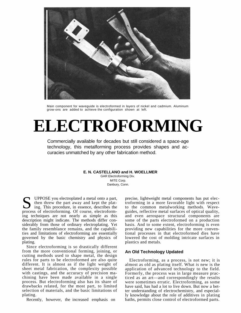
Main component for waveguide is electroformed in layers of nickel and cadmium. Aluminum grow-ons are added to achieve the configuration shown at left.
ELECTROFORMING
Commercially available for decades but still considered a space-age technology, this metalforming process provides shapes and ac-curacies unmatched by any other fabrication method.
E. N. CASTELLANO and H. WOELLMER GAR Electroforming Div.
MITE Corp. Danbury, Conn.
UPPOSE you electroplated a metal onto a part, then threw the part away and kept the plat-ing. This procedure, in essence, describes the
process of electroforming. Of course, electroform-ing techniques are not nearly as simple as this description might indicate. The methods differ con-siderably from those of ordinary electroplating. Yet the family resemblance remains, and the capabili-ties and limitations of electroforming are essentially governed by the basic chemistry and physics of plating.
Since electroforming is so drastically different from the more conventional forming, joining, or cutting methods used to shape metal, the design rules for parts to be electroformed are also quite different. It is almost as if the light weight of sheet metal fabrication, the complexity possible with castings, and the accuracy of precision ma-chining have been made available in a single process. But electroforming also has its share of drawbacks related, for the most part, to limited selection of materials, and the basic limitations of plating.
Recently, however, the increased emphasis on
precise, lightweight metal components has put elec-troforming in a more favorable light with respect to the common metalworking methods. Wave-guides, reflective metal surfaces of optical quality, and even aerospace structural components are some of the parts electroformed on a production basis. And to some extent, electroforming is even providing new capabilities for the more conven-tional processes in that electroformed dies have lowered the cost of molding intricate surfaces in plastics and metals.
An Old Technology Updated
Electroforming, as a process, is not new; it is almost as old as plating itself. What is new is the application of advanced technology to the field. Formerly, the process was in large measure prac-ticed as an art—and correspondingly the results were sometimes erratic. Electroforming, as some have said, has had a lot to live down. But now a bet-ter understanding of electrochemistry, and especial-ly knowledge about the role of additives in plating baths, permits close control of electroformed parts.
S
Results are now as reproducible as those obtained with welding, casting, forging, and other conven-tional techniques.
In electroforming, as in plating, metal ions are transferred electrochemically through an electrolyte from an anode to a surface where they are de-posited as atoms of plated metal. But in electro-forming, the surface that is to receive the plated metal, called a mandrel, is conditioned so that the plating does not adhere. Instead, the plated metal, or electroform, is lifted away and retains its as-deposited shape as a discrete component.
A part formed by this process has several un-usual characteristics:
∙ It can have extremely thin walls—less than one mil. In fact, minimum thickness is generally limited only by the fact that a part requires a certain amount of sturdiness to avoid being bent or broken by normal handling.
∙ Surface features of the mandrel are reproduced with extreme fidelity on the surface of the electroform. High surface finish and intricate detail are easily obtained.
• Complex contours are produced quite easily.
• Dimensional tolerances can be held to high accuracy. Accuracies of ±0.0001 in. are not unusual.
∙ Maximum size is limited only by the size of the available plating tank. Parts over 7 ft long have been successfully electroformed.
How the Process Affects Design As with most metalworking processes, the only
meaningful way to organize design guidelines for electroforming is to relate these guidelines to the details of the process itself. Also important is how design affects the cost of the electroform.
Mandrels: Probably the most interesting aspect
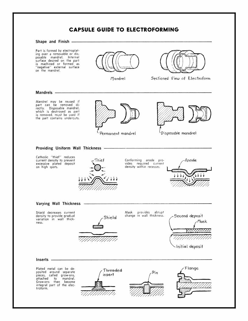
of electroforming is the ease with which complex shapes are produced. The mandrel and electroform bear the same geometric relationship that exists be-tween a mold and cast metal. Internal features of the electroform, therefore, are simply machined as negative-image external features on the mandrel.
Two types of mandrels are used: permanent and disposable. Permanent mandrels are used where the electroform has no undercut surfaces and can thus be lifted directly from the mandrel. Where undercuts are required on the electroform, the man-drel must be dissolved or melted away, or in some other way destroyed to be removed.
Stainless steel and aluminum are the materials most often used for mandrels. Stainless steel pol-ishes easily, providing high surface finish and high dimensional accuracy in the electroform. Internal (mandrel-facing) surfaces can be electroformed to 2 micro-in. rms. External surfaces are generally similar to that of a diecasting. Aluminum mandrels can be machined more easily, but do not provide the service life of stainless steel. Aluminum can be dissolved away and can thus serve as a disposable mandrel. Invar, low-melting bismuth alloys, and cast alloys of nickel or brass are used occasionally. Plaster, glass, quartz, wax, wood, and various plas-
tics and elastomers are also employed as mandrels. These materials are first made conductive with a surface coating. Mandrels must be handled with extreme care. The smallest imperfection—even a fine scratch—will reproduce on the electroformed part.
Of these materials, the castable ones are par-ticularly useful where large numbers of electro-forms must be produced with disposable mandrels. The mandrels can then be made economically in large numbers by casting them in reusable molds.
Because of the large number of available man-drel materials and the special features of each, a number of tradeoffs must be considered in design-ing the electroform. The disposable mandrels gen-erally cannot provide accuracy or surface finish as good as that provided by permanent mandrels. Every effort should therefore be made to avoid com-bining requirements for high accuracy or surface finish with undercut shapes. Small numbers of parts can be made economically—if functional re-quirements are not stringent—by using one of the low-cost mandrel materials such as wax or wood.
A number of different materials and special bond-ing techniques are sometimes employed to build up a mandrel where extreme accuracy must be combined with a complex shape. This type of man-drel construction is sometimes required for wave-guides and other electronic hardware having nu-merous cavities.
Most electroforms are produced over a positive, or male, mandrel. But sometimes accuracy or smooth surface finish is critical on the outside sur-face of the electroform, rather than on the inside surface. In such cases a negative, or female, man-drel is built.
Wall Thickness: Since plated metal is deposited
more or less uniformly, electroforms are essentially parts of constant wall thickness. Parts are produced with walls as thin as 0.005 in. One-half inch is gen-erally considered a practical maximum. Most elec-troforms are in the range of 0.010 to 0.050 in. thick.
Uniformity of the deposit is subject to the usual variations encountered in electroplating. Deposits build to greatest depth in areas of high plating-current concentration at sharp edges or on con-vex surfaces. Deposits are thinnest at low-current areas within recesses or on concave surfaces.
The easiest way to avoid either excess or insuf-ficient current density is to provide adequate radii at all edges and corners. Holes or slots should also be at least as wide as they are deep. If the electroform cannot be designed to these rules, the plater can use shields and "thieves" to reduce cur-rent density, or he can use conforming anodes to boost current density. Masks that prevent deposi-tion of metal in a given region are also used to produce variations in plating thickness.
Inserts and Grow-Ons: One aspect of the proc-
ess that makes electroforms particularly interest-ing is that the part need not be made entirely from deposited metal. Other materials, even non-conductors, can be incorporated into the compo-
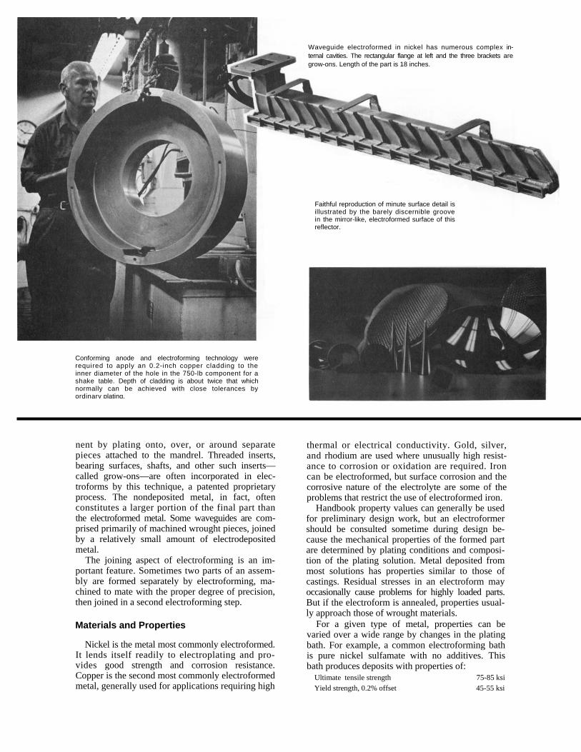
Waveguide electroformed in nickel has numerous complex in-ternal cavities. The rectangular flange at left and the three brackets are grow-ons. Length of the part is 18 inches.
Conforming anode and electroforming technology were required to apply an 0.2-inch copper cladding to the inner diameter of the hole in the 750-lb component for a shake table. Depth of cladding is about twice that which normally can be achieved with close tolerances by ordinary plating.
Faithful reproduction of minute surface detail is illustrated by the barely discernible groove in the mirror-like, electroformed surface of this reflector.
nent by plating onto, over, or around separate pieces attached to the mandrel. Threaded inserts, bearing surfaces, shafts, and other such inserts— called grow-ons—are often incorporated in elec-troforms by this technique, a patented proprietary process. The nondeposited metal, in fact, often constitutes a larger portion of the final part than the electroformed metal. Some waveguides are com-prised primarily of machined wrought pieces, joined by a relatively small amount of electrodeposited metal.
The joining aspect of electroforming is an im-portant feature. Sometimes two parts of an assem-bly are formed separately by electroforming, ma-chined to mate with the proper degree of precision, then joined in a second electroforming step.
Materials and Properties
Nickel is the metal most commonly electroformed. It lends itself readily to electroplating and pro-vides good strength and corrosion resistance. Copper is the second most commonly electroformed metal, generally used for applications requiring high
thermal or electrical conductivity. Gold, silver, and rhodium are used where unusually high resist-ance to corrosion or oxidation are required. Iron can be electroformed, but surface corrosion and the corrosive nature of the electrolyte are some of the problems that restrict the use of electroformed iron.
Handbook property values can generally be used for preliminary design work, but an electroformer should be consulted sometime during design be-cause the mechanical properties of the formed part are determined by plating conditions and composi-tion of the plating solution. Metal deposited from most solutions has properties similar to those of castings. Residual stresses in an electroform may occasionally cause problems for highly loaded parts. But if the electroform is annealed, properties usual-ly approach those of wrought materials.
For a given type of metal, properties can be varied over a wide range by changes in the plating bath. For example, a common electroforming bath is pure nickel sulfamate with no additives. This bath produces deposits with properties of:
Ultimate tensile strength 75-85 ksi Yield strength, 0.2% offset 45-55 ksi
Copyright 1968 by the Penton Publishing co., Cleveland, Ohio 44113
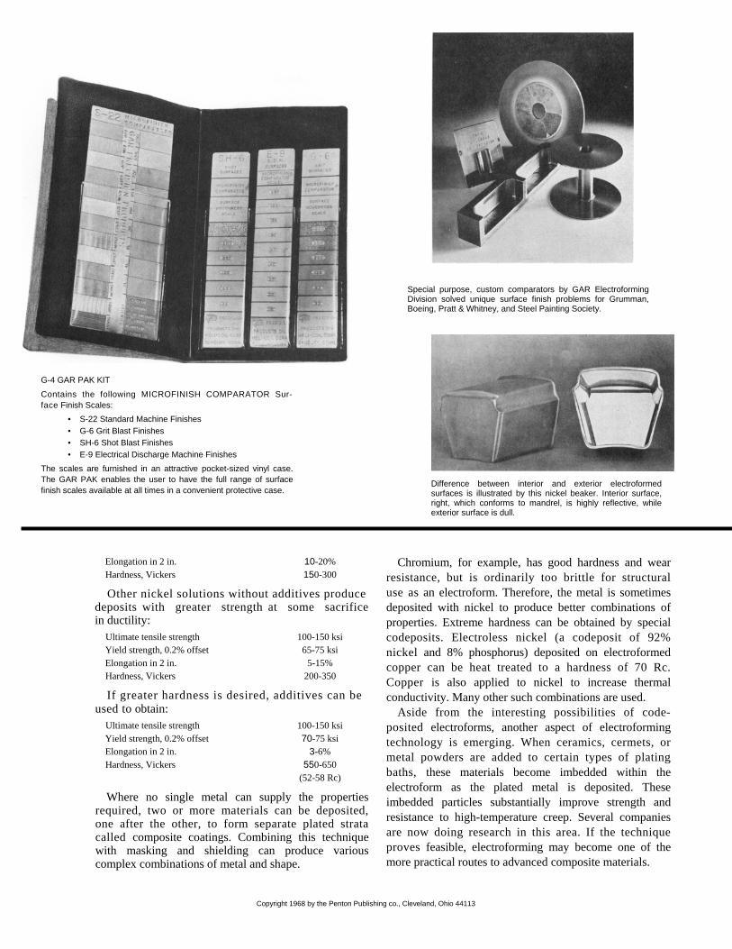
Special purpose, custom comparators by GAR Electroforming Division solved unique surface finish problems for Grumman, Boeing, Pratt & Whitney, and Steel Painting Society.
Difference between interior and exterior electroformed surfaces is illustrated by this nickel beaker. Interior surface, right, which conforms to mandrel, is highly reflective, while exterior surface is dull.
Elongation in 2 in. 10-20%Hardness, Vickers 150-300 Other nickel solutions without additives produce
deposits with greater strength at some sacrificein ductility:
Ultimate tensile strength 100-150 ksi Yield strength, 0.2% offset 65-75 ksi Elongation in 2 in. 5-15% Hardness, Vickers 200-350 If greater hardness is desired, additives can be
used to obtain: Ultimate tensile strength 100-150 ksi Yield strength, 0.2% offset 70-75 ksi Elongation in 2 in. 3-6% Hardness, Vickers 550-650 (52-58 Rc)
Where no single metal can supply the properties required, two or more materials can be deposited, one after the other, to form separate plated strata called composite coatings. Combining this technique with masking and shielding can produce various complex combinations of metal and shape.
Chromium, for example, has good hardness and wear resistance, but is ordinarily too brittle for structural use as an electroform. Therefore, the metal is sometimes deposited with nickel to produce better combinations of properties. Extreme hardness can be obtained by special codeposits. Electroless nickel (a codeposit of 92% nickel and 8% phosphorus) deposited on electroformed copper can be heat treated to a hardness of 70 Rc. Copper is also applied to nickel to increase thermal conductivity. Many other such combinations are used.
Aside from the interesting possibilities of code-posited electroforms, another aspect of electroforming technology is emerging. When ceramics, cermets, or metal powders are added to certain types of plating baths, these materials become imbedded within the electroform as the plated metal is deposited. These imbedded particles substantially improve strength and resistance to high-temperature creep. Several companies are now doing research in this area. If the technique proves feasible, electroforming may become one of the more practical routes to advanced composite materials.
G-4 GAR PAK KIT
Contains the following MICROFINISH COMPARATOR Sur-face Finish Scales:
• S-22 Standard Machine Finishes • G-6 Grit Blast Finishes • SH-6 Shot Blast Finishes • E-9 Electrical Discharge Machine Finishes
The scales are furnished in an attractive pocket-sized vinyl case. The GAR PAK enables the user to have the full range of surface finish scales available at all times in a convenient protective case.
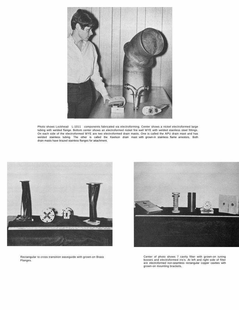
Photo shows Lockhead L-1011 components fabricated via electroforming. Center shows a nickel electroformed large tubing with welded flange. Bottom center shows an electroformed nickel fire wall WYE with welded stainless steel fittings. On each side of the electroformed WYE are two electroformed drain masts. One is called the APU drain mast and has welded stainless tubing. The other is called the Keelson drain mast with grown-in stainless flame arrestors. Both drain masts have brazed stainless flanges for attachment.
Rectangular to cross transition waveguide with grown-on Brass Flanges.
Center of photo shows 7 cavity filter with grown-on tuning bosses and electroformed iris's. At left and right side of filter are electroformed non-seamless rectangular copper cavities with grown-on mounting brackets.
For further information on solutions to specific electroforming problems, contact:
Eugene N. Castellano, General Manager GAR Electroforming Division/MITE Corporation
Augusta Drive
Danbury, Connecticut 06810 Tel. (203) 744-4300
Reprinted, with permission, from August 29, 1968 issue of MACHINE DESIGN.