Embed Size (px)
Citation preview

1
MaineDOTSEPTEMBER 2019
TrafficEngineeringStriping &StencilingHandbook

2
Section 1 & 2Striping Patterns/Layouts & Passing
Zone LayoutsSection 3
Truck Lane LayoutsSection 4
Turning Lane LayoutsSection 5 & 6
Stencil Layout,Square Footage
Points of ContactsRegion Traffic Engineers (RTE) List
Region 1 - SouthernRandy Illian - 855-7000
Bob VanLuling - 885-7000Region 2 – Midcoast
David Allen - 624-8227Region 3 - Western
Tim Soucie - 562-4228Region 4 - Eastern
Bruce Mattson - 941-4310**Andrew Allen - 941-4505
Region 5 - NorthernRaymond Demerchant - 764-2200
Erick Bechtel - 764-2200Additional Contact:
Noah French - 557-5429
**Contact for technical questions & future details

3
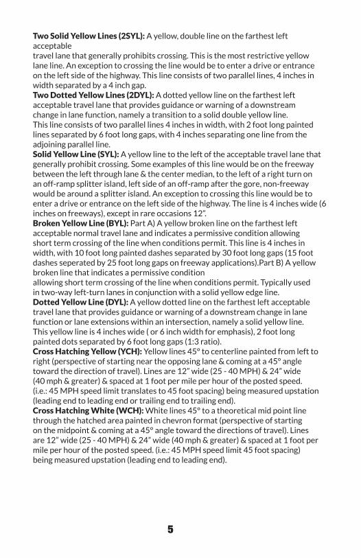
1. Passing zones shall not be less than 430 feet or 10 skips long (with 11 gaps).2. Traffic patterns are laid out using the basic “H” pattern. Use only the patterns on pages 8 & 9.3. All travel lanes have an assumed width of 11 feet unless otherwise marked (center of line to center of line). • All travel lanes must be properly identified. At the beginning of each end of the new pavement, the number reflecting the lane width should be painted on the road. (Example 10’, 10’-6’’, 11’, 11’-6’’, etc.) • Any tapering or widening of a travel lane, from the original desired width, shall be properly laid out to show the appropriate new taper or new widening along with the new desired width.4. All lanes, passing zones, intersections, islands, curve layouts, and truck lanes should follow the designs in this booklet.5. The listed Regional Traffic Engineers are the only individuals authorized to make changes to road layouts, passing zones, intersections, edge lines, truck lanes, and lane widths within each region.6. Any questions, concerns, or problems with the layouts need to be brought to the attention of the RTE in your region. The RTE contact information is on page 2.
Notes

4
DefinitionsSolid White Lines (SWL): Solid line pavement markings delineating the separationof traffic lanes that have the same direction of travel & where crossing the laneline markings is discouraged. This is also used in conjunction with tick marks inaggressive curves for additional visibility. Tick marks are 2 foot dots, attached tothe white line, that are 8 inches wide and gapped 6 feet between dots. Tickmarks run from the PC to the PT through the curve. When tick marks run throughan intersection the solid white line changes to a dotted white line forming a 12inch wide (8 inch + 4 inch) x 2 foot long dot.Broken White Line (BWL): Broken line pavement markings are used wherevercrossing the lane line is permitted. This line is 4 inches in width, with 10 foot longpainted lines separated by 30 foot long gaps. On the freeway they would be 6inch lines, 15 feet long with 25 foot gaps.Dotted White Line (DWL): A dotted lane line provides guidance or warning of adownstream change in lane function. A dotted line for lane extensions within anintersection should consist of 2 foot line segments and 6 foot gaps (1:3 ratio).A dotted line separating an auxiliary lane between two freeway interchangeor exit ramps involving lane drops should consist of 3 foot line segments and9 foot gaps. Dotted white lane lines that are used for lane drop markings andthat are used as a lane line separating through lanes from auxiliary lanes shouldconsist of line segments that are 3 feet in length separated by 9 foot gaps. A lanedrop marking used in advance of lane drops at freeway/expressway exit rampsshould begin at least 1/2 mile in advance of the theoretical gore. A dotted whiteline marking shall be used as the lane line to separate a through lane thatcontinues beyond the interchange or intersection from an adjacent lane under thefollowing conditions:A) A deceleration or acceleration lane,B) A through lane that becomes a mandatory exit or turn lane,C) An auxiliary lane 2 miles or less in length between an entrance ramp and anexit ramp,D) An auxiliary lane 1 mile or less in length between two adjacent intersections,E) Dotted line on a curve through an intersection.Two Solid White Lines (2SWL): A white, double line between travel lanes thatstrongly limits crossing. This is the most restrictive white lane lines. An exceptionto crossing this line would be to enter the roadway from a drive or entrance. Thisline consists of two parallel lines, 4 inches in width separated by a 4 inch gap.Stop Bar: Stop lines/bars shall consist of solid white lines, 24” wide,extending across approach lanes to indicate the point at which the stop isintended or required to be made.
5
Two Solid Yellow Lines (2SYL): A yellow, double line on the farthest leftacceptabletravel lane that generally prohibits crossing. This is the most restrictive yellowlane line. An exception to crossing the line would be to enter a drive or entranceon the left side of the highway. This line consists of two parallel lines, 4 inches inwidth separated by a 4 inch gap.Two Dotted Yellow Lines (2DYL): A dotted yellow line on the farthest leftacceptable travel lane that provides guidance or warning of a downstreamchange in lane function, namely a transition to a solid double yellow line.This line consists of two parallel lines 4 inches in width, with 2 foot long paintedlines separated by 6 foot long gaps, with 4 inches separating one line from theadjoining parallel line.Solid Yellow Line (SYL): A yellow line to the left of the acceptable travel lane thatgenerally prohibit crossing. Some examples of this line would be on the freewaybetween the left through lane & the center median, to the left of a right turn onan off-ramp splitter island, left side of an off-ramp after the gore, non-freewaywould be around a splitter island. An exception to crossing this line would be toenter a drive or entrance on the left side of the highway. The line is 4 inches wide (6 inches on freeways), except in rare occasions 12”.Broken Yellow Line (BYL): Part A) A yellow broken line on the farthest leftacceptable normal travel lane and indicates a permissive condition allowingshort term crossing of the line when conditions permit. This line is 4 inches inwidth, with 10 foot long painted dashes separated by 30 foot long gaps (15 foot dashes seperated by 25 foot long gaps on freeway applications).Part B) A yellow broken line that indicates a permissive conditionallowing short term crossing of the line when conditions permit. Typically usedin two-way left-turn lanes in conjunction with a solid yellow edge line.Dotted Yellow Line (DYL): A yellow dotted line on the farthest left acceptabletravel lane that provides guidance or warning of a downstream change in lanefunction or lane extensions within an intersection, namely a solid yellow line.This yellow line is 4 inches wide ( or 6 inch width for emphasis), 2 foot longpainted dots separated by 6 foot long gaps (1:3 ratio).Cross Hatching Yellow (YCH): Yellow lines 45° to centerline painted from left toright (perspective of starting near the opposing lane & coming at a 45° angletoward the direction of travel). Lines are 12” wide (25 - 40 MPH) & 24” wide(40 mph & greater) & spaced at 1 foot per mile per hour of the posted speed.(i.e.: 45 MPH speed limit translates to 45 foot spacing) being measured upstation(leading end to leading end or trailing end to trailing end).Cross Hatching White (WCH): White lines 45° to a theoretical mid point linethrough the hatched area painted in chevron format (perspective of startingon the midpoint & coming at a 45° angle toward the directions of travel). Linesare 12” wide (25 - 40 MPH) & 24” wide (40 mph & greater) & spaced at 1 foot permile per hour of the posted speed. (i.e.: 45 MPH speed limit 45 foot spacing)being measured upstation (leading end to leading end).

6

7
Drawings in this book are not to scale.
8
Section 1
2
7
12
3
8
13
4
9
14
5
10
15
1
6
11

9
20'' to 24''
8'' to12''
Final centerline markings are to be placed where the centerline will be striped. The striping truck may need to stripe from either direction, depending upon the direction of the sun. Marks must be placed on the high point (“center line joint”) because marks under the tire of the striping truck cannot be seen by the operator. One foot off the centerline joint is not acceptable.
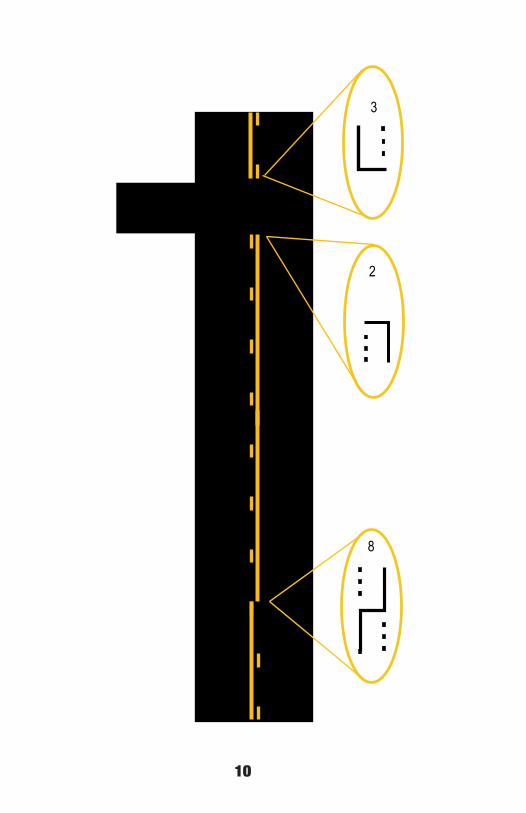
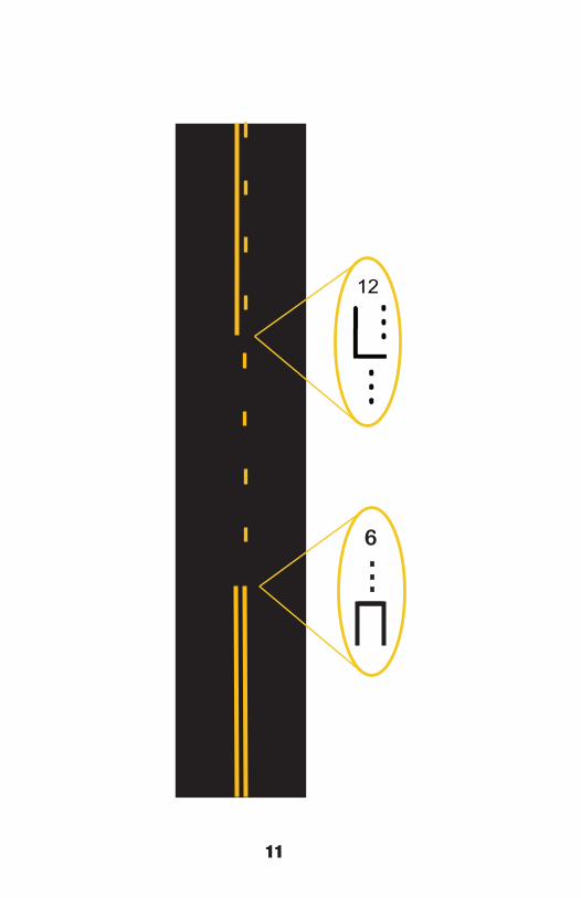
Center Line Markings & 5 Dot Patterns (For Dotted Lines)
16 17 18 19
Edge Line Markings (white)
20 21 22
23 24 25
10
8
3
2
11

12
30 ft
10 ft .
99
1313
19
18
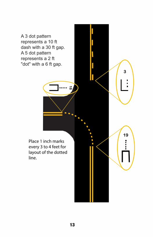
Place 1 inch marksevery 3 to 4 feet forlayout of the dottedline.
3
A 3 dot patternrepresents a 10 ftdash with a 30 ft gap.A 5 dot pattern represents a 2 ft "dot" with a 6 ft gap.

14
��
17
16
23
21
20
24
22
START PROJECT
12 inch dotted line (8” + 4”)
4 inch line with 8 inch x 24 inchtick marks

15

16
Section 2
Spacing for 25 - 30 MPH
200’
100 FT spacing when total length of center turn lane is less than 1,000 FT in length
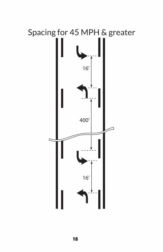
45º
25’ at 25 MPH30’ at 30 MPH..35’ at 35 MPH40’ at 40 MPH45’ at 45 MPH50’ at 50 MPH55’ at 55 MPH
*Crosshatching: Width of diagonals equals 12” if <45 MPH, 24” if > 45 MPH
16’
16’
30’
10’
17
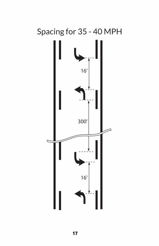
Spacing for 35 - 40 MPH
300’
16’
16’
18
Spacing for 45 MPH & greater
400’
16’
16’

19
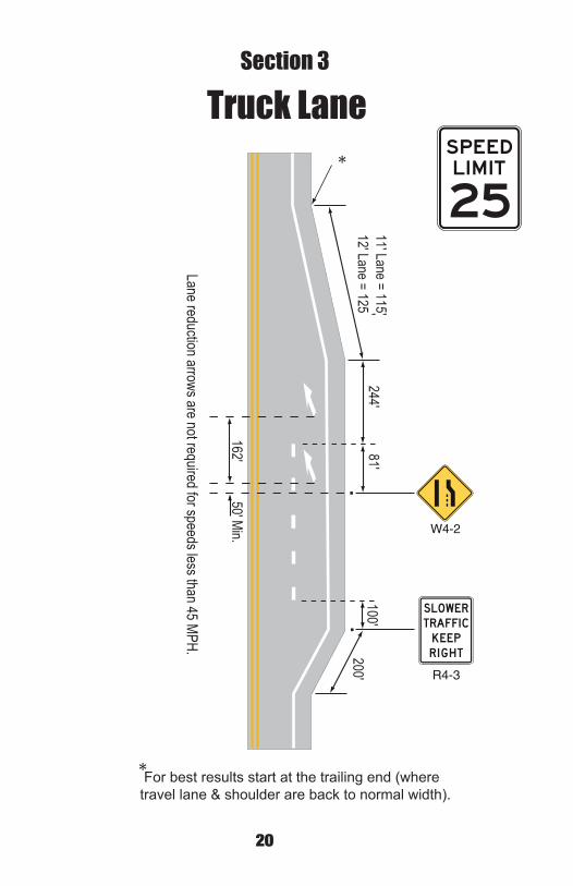
20
W4-2
R4-3
'
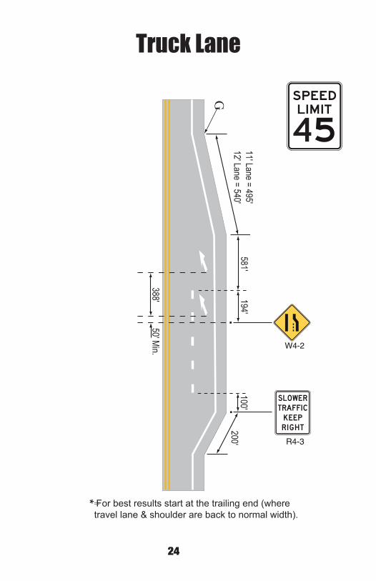
For best results start at the trailing end (where travel lane & shoulder are back to normal width).
*
*
Lane reduction arrows are not required for speeds less than 45 MPH.
Truck LaneSection 3
21
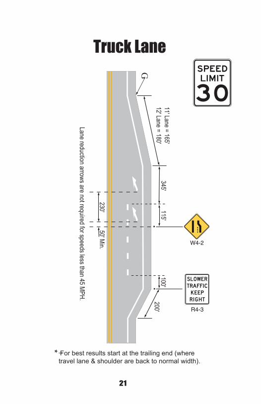
W4-2
R4-3
=For best results start at the trailing end (wheretravel lane & shoulder are back to normal width).
G
*
Lane reduction arrows are not required for speeds less than 45 MPH.
Truck Lane

22
W4-2
R4-3
=For best results start at the trailing end (wheretravel lane & shoulder are back to normal width).
G
*
Lane reduction arrows are not required for speeds less than 45 MPH.
Truck Lane
23
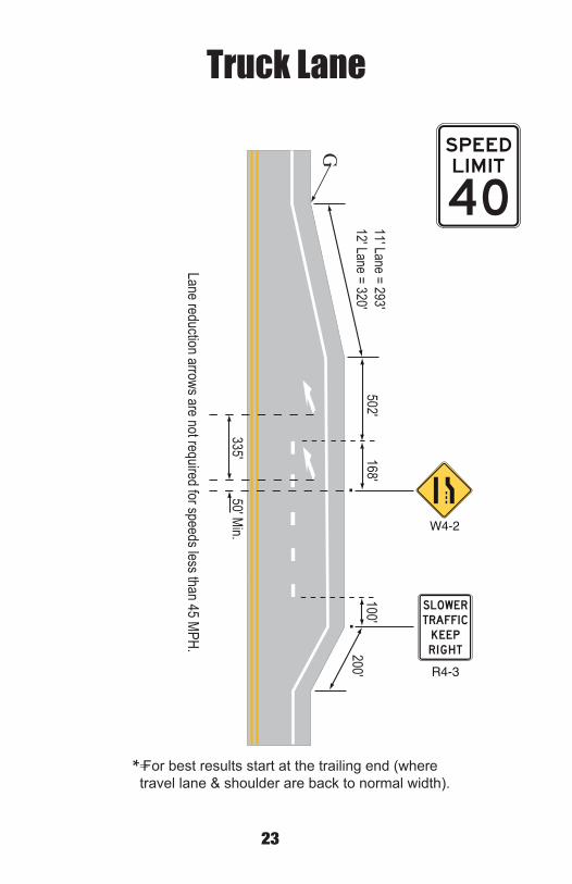
W4-2
R4-3
=For best results start at the trailing end (wheretravel lane & shoulder are back to normal width).
G
*
Truck Lane
24
W4-2
R4-3
=For best results start at the trailing end (wheretravel lane & shoulder are back to normal width).
G
*
Truck Lane

25
W4-2
R4-3
=For best results start at the trailing end (wheretravel lane & shoulder are back to normal width).
G
*
Truck Lane

26
W4-2
R4-3
=For best results start at the trailing end (wheretravel lane & shoulder are back to normal width).
G
*
Truck Lane

27
W4-2
R4-3
For best results start at the trailing end (wheretravel lane & shoulder are back to normal width).
*
*
Truck Lane
28
NO
RM
AL
WID
THFL
USH
CONC
RETE
D/4
D =
325
'1/
2 W
L =
10.4
2 x
W
1/2
W
1/2
L
50'
MIN
*LR
TMLA
YO
UT
D/3
D/3
D/2
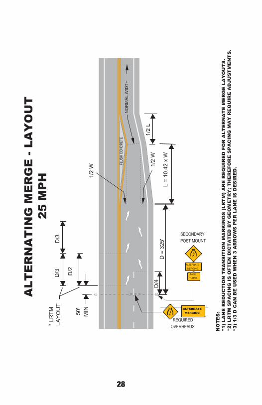
REQUIRED OVERHEADS
ALTERNATE MERGING
TAKE TURNS
SECONDARYPOST MOUNT
ALTERNATE MERGING
ALT
ER
NA
TIN
G M
ER
GE
- LA
YO
UT
25
MP
H
NO
TE
S:
*1)
LAN
E R
ED
UC
TIO
N T
RA
NS
ITIO
N M
AR
KIN
GS
(LR
TM
) A
RE
RE
QU
IRE
D F
OR
ALT
ER
NA
TE
ME
RG
E L
AY
OU
TS
.*2
) LR
TM
SP
AC
ING
IS
OFT
EN
DIC
TA
TE
D B
Y G
EO
ME
TR
Y; T
HE
RE
FOR
E S
PA
CIN
G M
AY
RE
QU
IRE
AD
JUS
TM
EN
TS
.*3
) 1/
3 D
CA
N B
E U
SE
D W
HE
N 3
AR
RO
WS
PE
R L
AN
E I
S D
ES
IRE
D.
• • • •
29
NO
RM
AL
WID
THFL
USH
CONC
RETE
D/4
D =
460
'1/
2 W
L =
15 x
W
1/2
W
1/2
L
50'
MIN
*LR
TMLA
YO
UT
D/3
D/3
D/2
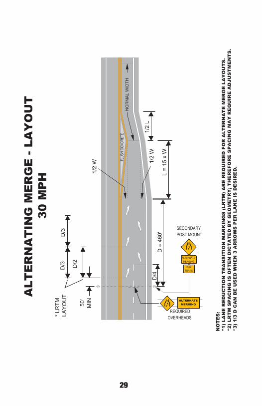
REQUIRED OVERHEADS
ALTERNATE MERGING
TAKE TURNS
SECONDARYPOST MOUNT
ALTERNATE MERGING
ALT
ER
NA
TIN
G M
ER
GE
- LA
YO
UT
30
MP
H
NO
TE
S:
*1)
LAN
E R
ED
UC
TIO
N T
RA
NS
ITIO
N M
AR
KIN
GS
(LR
TM
) A
RE
RE
QU
IRE
D F
OR
ALT
ER
NA
TE
ME
RG
E L
AY
OU
TS
.*2
) LR
TM
SP
AC
ING
IS
OFT
EN
DIC
TA
TE
D B
Y G
EO
ME
TR
Y; T
HE
RE
FOR
E S
PA
CIN
G M
AY
RE
QU
IRE
AD
JUS
TM
EN
TS
.*3
) 1/
3 D
CA
N B
E U
SE
D W
HE
N 3
AR
RO
WS
PE
R L
AN
E I
S D
ES
IRE
D.
• • • •

30
NO
RM
AL
WID
THFL
USH
CONC
RETE
D/4
D =
565
'1/
2 W
L =
20.4
2 x
W
1/2
W
1/2
L
50'
MIN
*LR
TMLA
YO
UT
D/3
D/3
D/2
REQUIRED OVERHEAD
ALTERNATE MERGING
TAKETURNS
SECONDARYPOST MOUNT
ALTERNATEMERGING
ALT
ER
NA
TIN
G M
ER
GE
- LA
YO
UT
35
MP
H
NO
TE
S:
*1)
LAN
E R
ED
UC
TIO
N T
RA
NS
ITIO
N M
AR
KIN
GS
(LR
TM
) A
RE
RE
QU
IRE
D F
OR
ALT
ER
NA
TE
ME
RG
E L
AY
OU
TS
.*2
) LR
TM
SP
AC
ING
IS
OFT
EN
DIC
TA
TE
D B
Y G
EO
ME
TR
Y; T
HE
RE
FOR
E S
PA
CIN
G M
AY
RE
QU
IRE
AD
JUS
TM
EN
TS
.*3
) 1/
3 D
CA
N B
E U
SE
D W
HE
N 3
AR
RO
WS
PE
R L
AN
E I
S D
ES
IRE
D.
• • • •

31
NO
RM
AL
WID
THFL
USH
CONC
RETE
D/4
D =
670
'1/
2 W
L =
26.6
7 x
W
1/2
W
1/2
L
50'
MIN
*LR
TMLA
YO
UT
D/3
D/3
D/2
REQUIRED OVERHEADS
ALTERNATE MERGING
TAKE TURNS
SECONDARYPOST MOUNT
ALTERNATE MERGING
ALT
ER
NA
TIN
G M
ER
GE
- LA
YO
UT
40
MP
H
NO
TE
S:
*1)
LAN
E R
ED
UC
TIO
N T
RA
NS
ITIO
N M
AR
KIN
GS
(LR
TM
) A
RE
RE
QU
IRE
D F
OR
ALT
ER
NA
TE
ME
RG
E L
AY
OU
TS
.*2
) LR
TM
SP
AC
ING
IS
OFT
EN
DIC
TA
TE
D B
Y G
EO
ME
TR
Y; T
HE
RE
FOR
E S
PA
CIN
G M
AY
RE
QU
IRE
AD
JUS
TM
EN
TS
.*3
) 1/
3 D
CA
N B
E U
SE
D W
HE
N 3
AR
RO
WS
PE
R L
AN
E I
S D
ES
IRE
D.
• • • •

32
NO
RM
AL
WID
THFL
USH
CONC
RETE
D/4
D =
775
'1/
2 W
L =
45 x
W
1/2
W
1/2
L
50'
MIN
*LR
TMLA
YO
UT
D/3
D/3
D/2
REQUIRED OVERHEADS
ALTERNATE MERGING
TAKE TURNS
SECONDARYPOST MOUNT
ALTERNATE MERGING
ALT
ER
NA
TIN
G M
ER
GE
- LA
YO
UT
45
MP
H
NO
TE
S:
*1)
LAN
E R
ED
UC
TIO
N T
RA
NS
ITIO
N M
AR
KIN
GS
(LR
TM
) A
RE
RE
QU
IRE
D F
OR
ALT
ER
NA
TE
ME
RG
E L
AY
OU
TS
.*2
) LR
TM
SP
AC
ING
IS
OFT
EN
DIC
TA
TE
D B
Y G
EO
ME
TR
Y; T
HE
RE
FOR
E S
PA
CIN
G M
AY
RE
QU
IRE
AD
JUS
TM
EN
TS
.*3
) 1/
3 D
CA
N B
E U
SE
D W
HE
N 3
AR
RO
WS
PE
R L
AN
E I
S D
ES
IRE
D.
• • • •

33
NO
RM
AL
WID
THFL
USH
CONC
RETE
D/4
D =
885
'1/
2 W
L =
50 x
W
1/2
W
1/2
L
50'
MIN
*LR
TMLA
YO
UT
D/3
D/3
D/2
REQUIRED OVERHEAD
ALTERNATE
MERGING
TAKETURNS
SECONDARYPOST MOUNT
ALTERNATEMERGING
ALT
ER
NA
TIN
G M
ER
GE
- LA
YO
UT
50
MP
H
NO
TE
S:
*1)
LAN
E R
ED
UC
TIO
N T
RA
NS
ITIO
N M
AR
KIN
GS
(LR
TM
) A
RE
RE
QU
IRE
D F
OR
ALT
ER
NA
TE
ME
RG
E L
AY
OU
TS
.*2
) LR
TM
SP
AC
ING
IS
OFT
EN
DIC
TA
TE
D B
Y G
EO
ME
TR
Y; T
HE
RE
FOR
E S
PA
CIN
G M
AY
RE
QU
IRE
AD
JUS
TM
EN
TS
.*3
) 1/
3 D
CA
N B
E U
SE
D W
HE
N 3
AR
RO
WS
PE
R L
AN
E I
S D
ES
IRE
D.
• • • •
34
NO
RM
AL
WID
THFL
USH
CONC
RETE
D/4
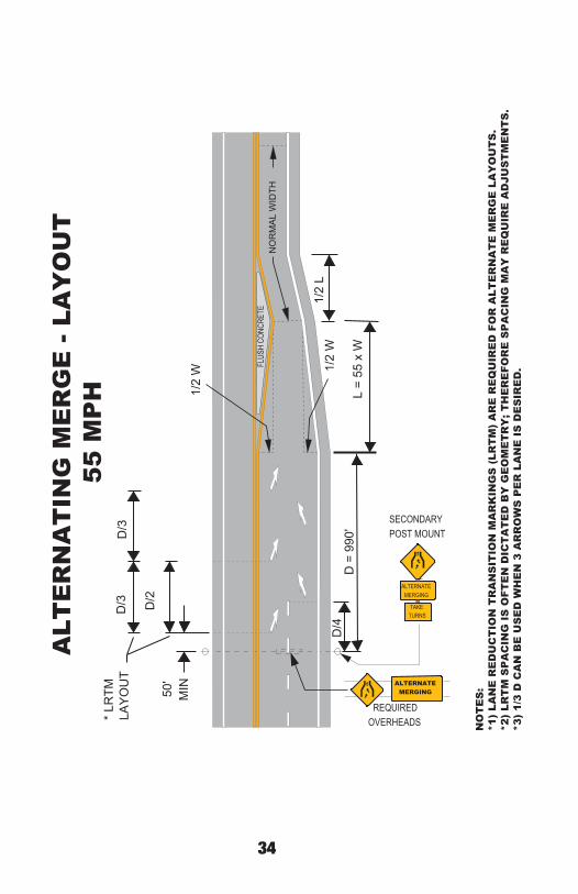
D =
990
'1/
2 W
L =
55 x
W
1/2
W
1/2
L
50'
MIN
*LR
TMLA
YO
UT
D/3
D/3
D/2
REQUIRED OVERHEADS
ALTERNATE MERGING
TAKE TURNS
SECONDARYPOST MOUNT
ALTERNATE MERGING
ALT
ER
NA
TIN
G M
ER
GE
- LA
YO
UT
55
MP
H
NO
TE
S:
*1)
LAN
E R
ED
UC
TIO
N T
RA
NS
ITIO
N M
AR
KIN
GS
(LR
TM
) A
RE
RE
QU
IRE
D F
OR
ALT
ER
NA
TE
ME
RG
E L
AY
OU
TS
.*2
) LR
TM
SP
AC
ING
IS
OFT
EN
DIC
TA
TE
D B
Y G
EO
ME
TR
Y; T
HE
RE
FOR
E S
PA
CIN
G M
AY
RE
QU
IRE
AD
JUS
TM
EN
TS
.*3
) 1/
3 D
CA
N B
E U
SE
D W
HE
N 3
AR
RO
WS
PE
R L
AN
E I
S D
ES
IRE
D.
• • • •
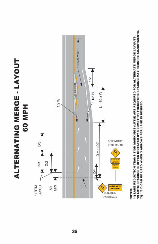
35
NO
RM
AL
WID
THFL
USH
CONC
RETE
D/4
D =
110
0'1/
2 W
L =
60 x
W
1/2
W
1/2
L
50'
MIN
*LR
TMLA
YO
UT
D/3
D/3
D/2
REQUIRED OVERHEADS
ALTERNATE MERGING
TAKE TURNS
SECONDARYPOST MOUNT
ALTERNATE MERGING
ALT
ER
NA
TIN
G M
ER
GE
- LA
YO
UT
60
MP
H
NO
TE
S:
*1)
LAN
E R
ED
UC
TIO
N T
RA
NS
ITIO
N M
AR
KIN
GS
(LR
TM
) A
RE
RE
QU
IRE
D F
OR
ALT
ER
NA
TE
ME
RG
E L
AY
OU
TS
.*2
) LR
TM
SP
AC
ING
IS
OFT
EN
DIC
TA
TE
D B
Y G
EO
ME
TR
Y; T
HE
RE
FOR
E S
PA
CIN
G M
AY
RE
QU
IRE
AD
JUS
TM
EN
TS
.*3
) 1/
3 D
CA
N B
E U
SE
D W
HE
N 3
AR
RO
WS
PE
R L
AN
E I
S D
ES
IRE
D.
• • • •
36
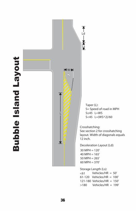
L
Ls
Ld
W
Taper (L): S= Speed of road in MPHS 45 L=WS S<45 L=(WS^2)/60
Crosshatching:See section 2 for crosshatchinglayout. Width of diagonals equals12 inch.
Deceleration Layout (Ld):
30 MPH = 120’ 40 MPH = 165’ 50 MPH = 265’ 60 MPH = 370’
Storage Length (Ls): <61 Vehicles/HR = 50’ 61-120 Vehicles/HR = 100’121-180 Vehicles/HR = 150’>180 Vehicles/HR = 199’
Bub
ble
Isla
nd L
ayou
t

37
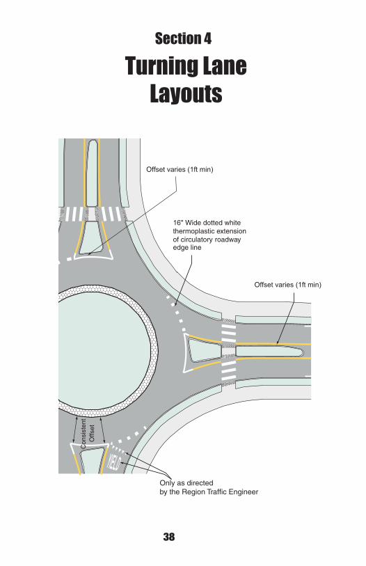
38
Turning LaneLayouts
O
Wide dotted white extension
of circulatory roadway edge line
O
Con
sist
ent
O
Only as directedby the Region Traffic Engineer
Section 4

39
Signalized Intersectionwith Multiple Turn Lanes
100' to 300' length unless Region Traffic Engineer determins a longer solid line is needed.
2' x 8'' dotted line with 6' gap when a through lane become a manda-tory turn lane.
Used (required) when through lane becomes mandatory turn lane.
2' x 8'' dottedline with a 6' gap.
Optional 2nd only & 3rd arrow.
Solid line (may be broken line where no auxiliary turn lane exists)
12'' to 24''

40
Railroad Crossing
The “R’s” wear offin the wheel paths, therefore this narrow layout is always used
Minimum15’
24’
If automatic gate is present, stop bar must be at a minimum of 8 feet prior to approaching the gate.
20’
16’
15’
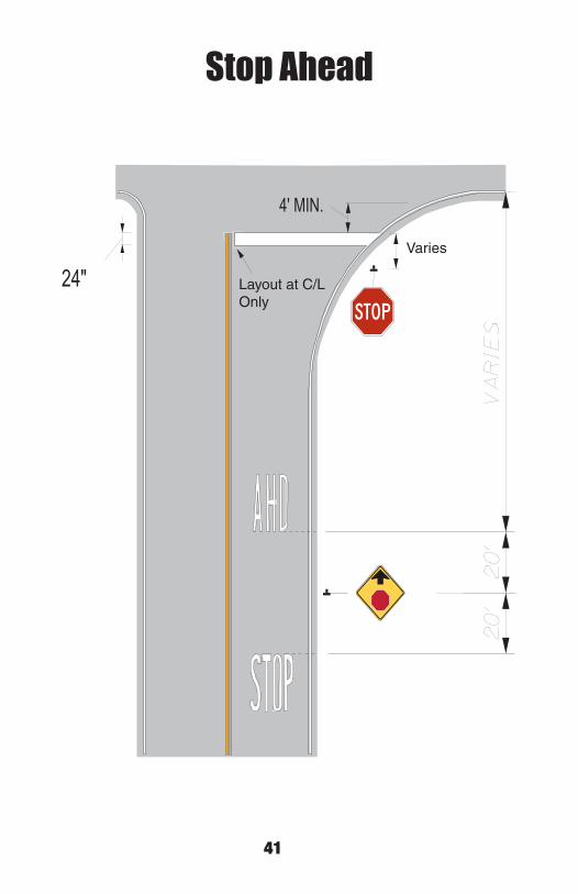
41
24"
4' MIN.
Stop Ahead
Varies
Layout at C/L Only

42
MIN.
20
'
50'
50'
6'
Lane Designation Layout
A third arrow may be added when a through lane becomes a turn lane or at the leading end of an auxiliary lane (longer than 250'.)
Lane separation lines & designation markings should start 10' past the beginning of the auxiliary lane when the auxiliary lane is longer than 110'.
2' x 4'' line & 6' gap can be used when in a curve.
Through lane becomes turn lane: The line is 8'' wide and the leading dashes (dots) are 2' L x 8'' W x6' gap (length of dots is determined by Region Traffic Engineer.)
4’ M
in.

43
Stop & Yield30
'30
'
30'
Max.Yellowwhenislandis raised(fullheight)
6'
4'Min.
24''
Layout only the 1sttriangle
4' Min.

44
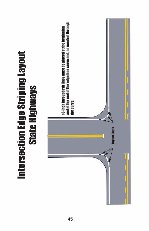
Inte
rsec
tion E
dge S
tripi
ng La
yout
Stat
e Aid
High
ways
18-in
ch la
yout
dash
lines
mus
t be p
lace
d at t
he be
ginn
ing
and a
t the
end o
f the
edge
line c
urve
and,
as ne
eded
, thro
ugh
the c
urve
.
45
Layo
ut Li
nes
Inte
rsec
tion E
dge S
tripi
ng La
yout
Stat
e Hig
hway
s
18-in
ch la
yout
dash
lines
mus
t be p
lace
d at t
he be
ginn
ing
and a
t the
end o
f the
edge
line c
urve
and,
as ne
eded
, thro
ugh
the c
urve
.

46
75' to
100' 12” t
o 24”
Layo
ut lin
es pl
aced
as ne
eded
Isla
nd St
ripin
g Lay
out
47
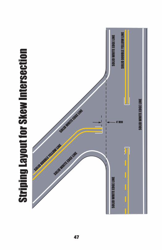
SOLID
WHI
TE ED
GE LI
NE
SOLID DOUBLE YELLOW LINE
SOLID
DOUB
LE YE
LLOW
LINE
SOLID
WHI
TE ED
GE LI
NESO
LID W
HITE
EDGE
LINE
SOLID WHITE EDGE LINE
SOLID WHITE EDGE LINE
4’ MIN
Strip
ing L
ayou
t for
Skew
Inte
rsec
tion

48
PT
PCPC
PC
PT
PT 18” dash line
Edge Line Layoutfor Curves
Place 18’’ long layout marks every200 to 400 feet in curves (beginning at the PC and ending at the PT).Marks should be spaced every 200 to 400 feet for sharp curves and every 400 to 500 feet for gradual curves).
49
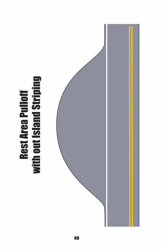
Rest
Area
Pullo
ffwi
th ou
t Isla
nd St
ripin
g

50
Rest
Area
with
Isla
nd St
ripin
g Lay
out

51
Inte
rsec
tion E
dge S
tripi
ng La
yout
Non S
tate
-Aid
Road
s

52

53
5.3 SF 7.1 SF
4.7 SF 6.2 SF
6.3 SF 4.7 SF
5 SF 7 SF
5 SF 6 SF
6 SF 5 SF
ACTUALAREA
PAY AREA
8'-0"
Section 5
5• •
Section 5
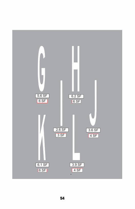
54
5.6 SF 6.2 SF
2.6 SF 3.6 SF
6.1 SF 3.9 SF
6 SF 6 SF
3 SF 4 SF
6 SF 4 SF5• •

55
7.4 SF 7.2 SF
5.8 SF 5.3 SF
6.1 SF 6.3 SF
7 SF 7 SF
6 SF 5 SF
6 SF 6 SF5• •
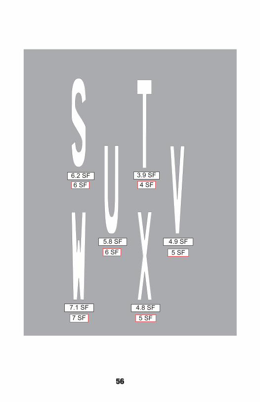
56
6.2 SF 3.9 SF
5.8 SF 4.9 SF
7.1 SF 4.8 SF
6 SF 4 SF
6 SF 5 SF
7 SF 5 SF5• •

57
3.9 SF 5.1 SF
2.6 SF 6.2 SF
5.6 SF 5.2 SF
4 SF 5 SF
3 SF 6 SF
6 SF 5 SF5• •
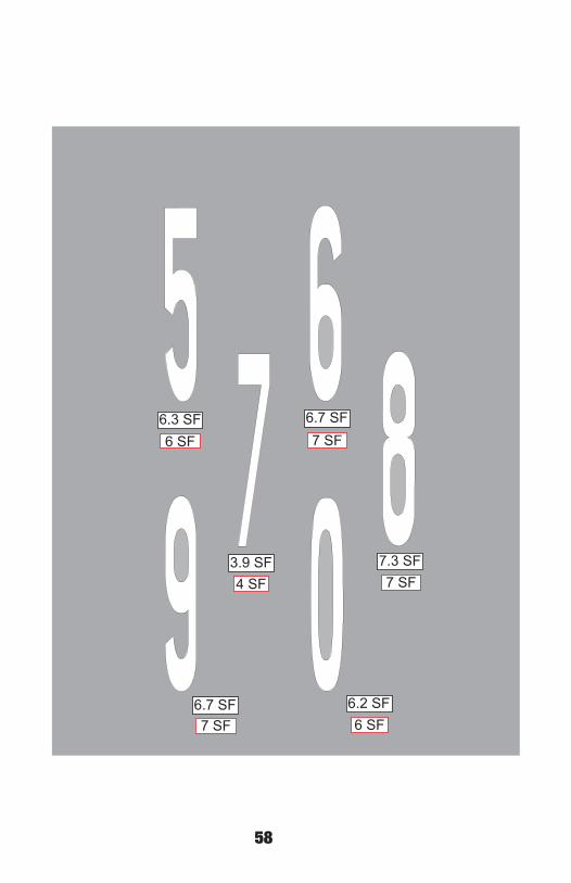
58
6.3 SF 6.7 SF
3.9 SF 7.3 SF
6.7 SF 6.2 SF
6 SF 7 SF
4 SF 7 SF
7 SF 6 SF5• •

59
31.4 SF
30.7 SF
31 SF
31 SF5• •

60
30.3 SF
30.9 SF 31 SF
30 SF• • • •

61
31.4 SF
30.4 SF
31 SF
30 SF6• •
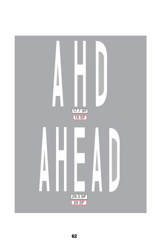
62
29.3 SF29 SF
17.7 SF18 SF
6• •

63
19.9 SF
20 SF
19.1 SF19 SF
6• •
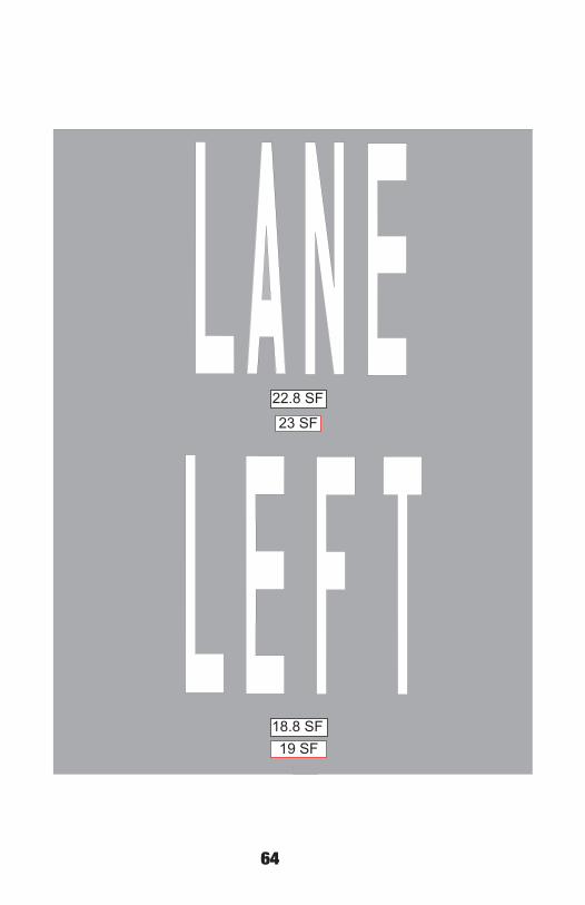
64
18.8 SF19 SF
22.8 SF
23 SF
6• •

65
17.8 SF18 SF
20.9 SF
21 SF
6• •
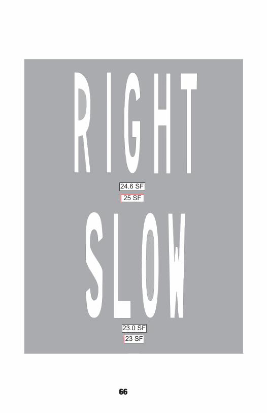
66
24.6 SF
25 SF
23.0 SF23 SF
6• •
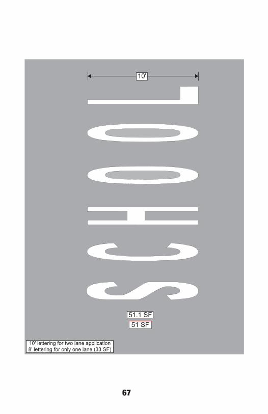
67
51.1 SF51 SF
10'
10' lettering for two lane application8' lettering for only one lane (33 SF) 6• •

68
23.2 SF
23 SF
30.9 SF31 SF
6• •
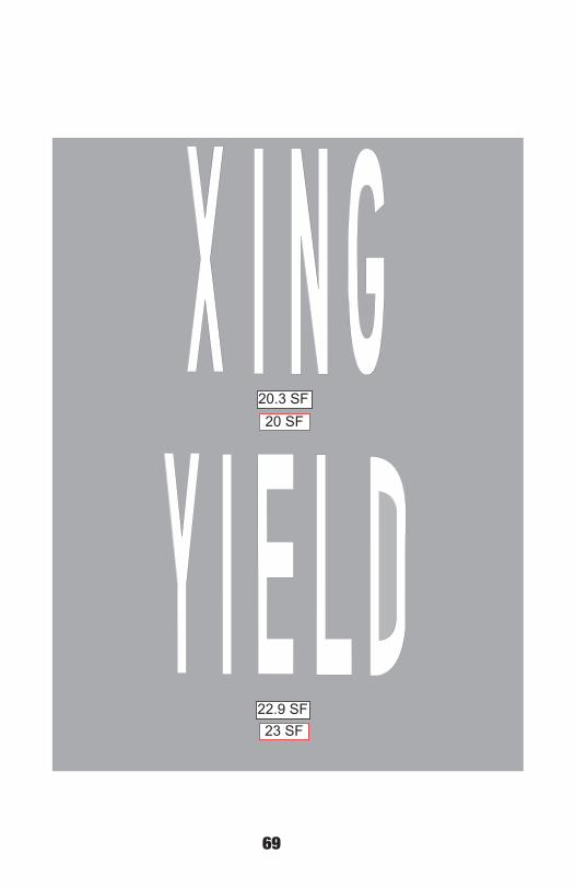
69
22.9 SF23 SF
20.3 SF20 SF
6• •

70

71
4.5
SF
5S
F
6'
3'-4
"
Bik
ew
ithP
asse
nger
5.6
SF
6S
F3'
-4"
6'
7• •
Section 6
Bik
eLa
neM
arke
rSection 6

72
9.4 SF9 SF
3'-4"
6'
3'-7"
9'-6"
Sharrow (Shared Bike Lane Marker)
7• •

73
6'3"
3'-6"
7.92 SF
8 SF
PEDESTRIAN CROSSING

74
3.9 SF
15.9 SF
4 SF
16 SF
2'
2'-4"
4'
4'
Handicap Markers
7• •

75
95.6 SF96 SF
71.7 SF72 SF
Hospital Symbols(high speed/low speed)
8' 12'16'
6'
6'
7• •

76
11.4 SF
15.6 SF
11 SF
16 SF
9'-6"
8'
Straight Only Arrow
Left Only Arrow
7• •

77
36.6 SF
37 SF
Any Direction Arrow
11'-2"
Right or Left Option Arrow
27.5 SF28 SF
11'-2"
8'
7• •
11'-6"

78
24.9 SF
25 SF
11'-6"
7'-6"
Left of Straight Option Arrow
7• •
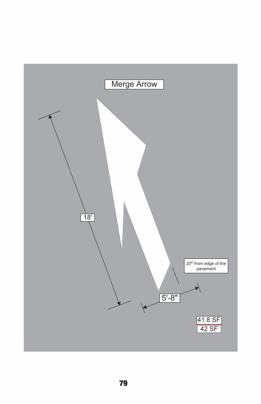
79
41.8 SF42 SF
20o from edge of thepavement
Merge Arrow
7• •
18'
5'-8"

80
27.5 SF 35.0 SF27 SF 35 SF
18'-8"
2'-8"
7'
13'-8"
6'-6"
Roundabout Arrows(Type LE & TRE)
7• •

81
28.2 SF 36.7 SF
28 SF 37 SF
18'-8"18'-8"
6'
Roundabout Arrows(Types TE & LTE)
4'
• • • •

82
22.9 SF 43.5 SF23 SF 43 SF
18'-8"18'-8"
9'
Roundabout Arrows(Types T & LTRE)
4'
8• •
83
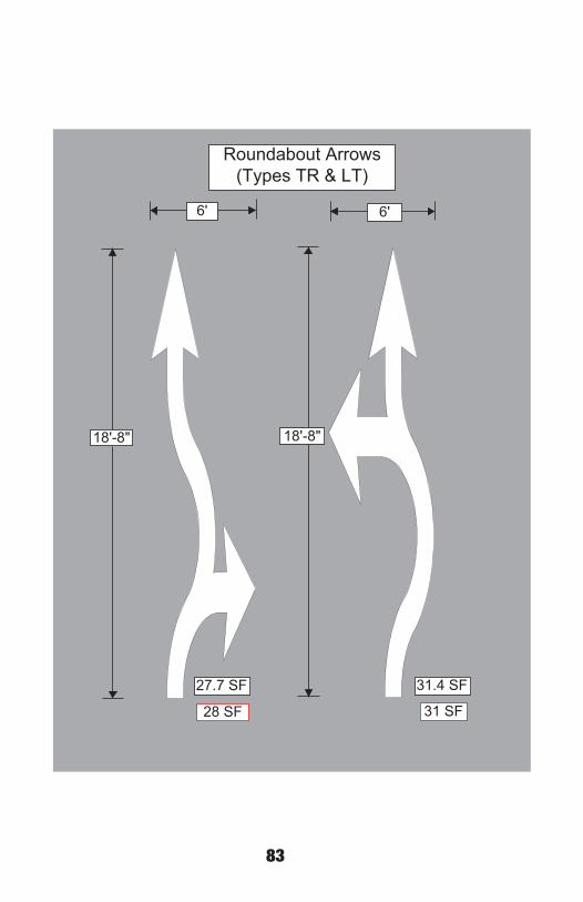
27.7 SF 31.4 SF
28 SF 31 SF
18'-8"18'-8"
6'6'
Roundabout Arrows(Types TR & LT)
8• •
84
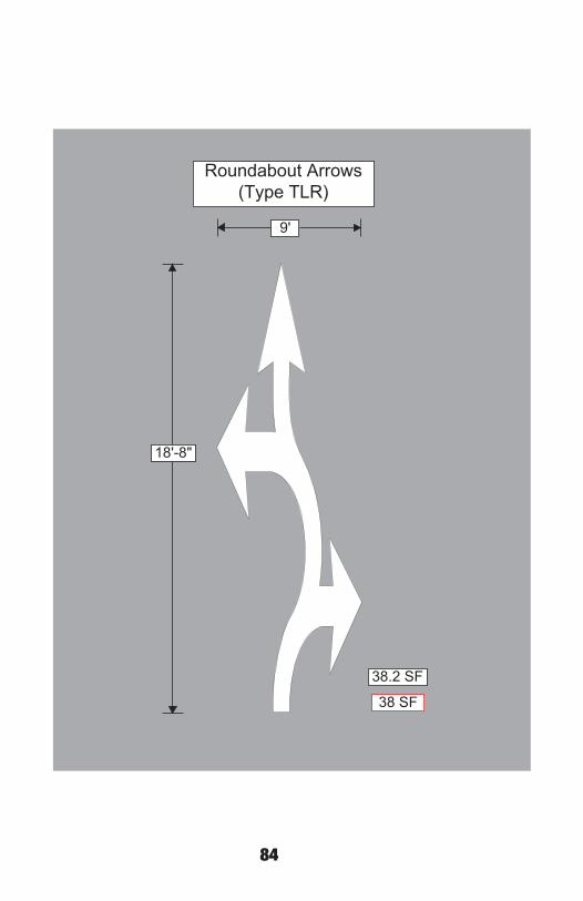
38.2 SF
38 SF
18'-8"
9'
Roundabout Arrows(Type TLR)
8• •

85
41.4 SF
41 SF
9'-6"
12'
Large Speed BumpWarning Marker
11.9 SF12 SF
6'
6'
Small Speed BumpWarning Marker
8• •
86
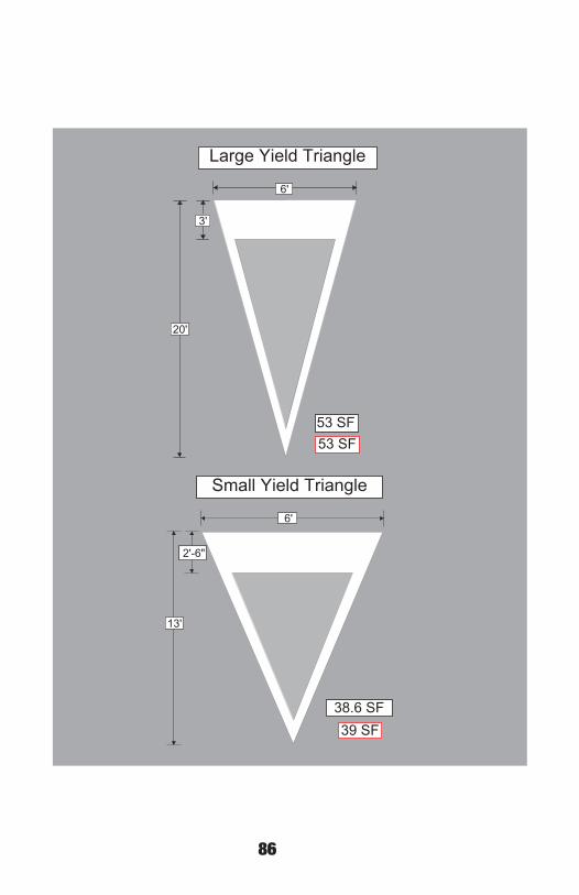
53 SF53 SF
6'
3'
20'
Large Yield Triangle
38.6 SF39 SF
6'
2'-6"
13'
Small Yield Triangle
8• •
87
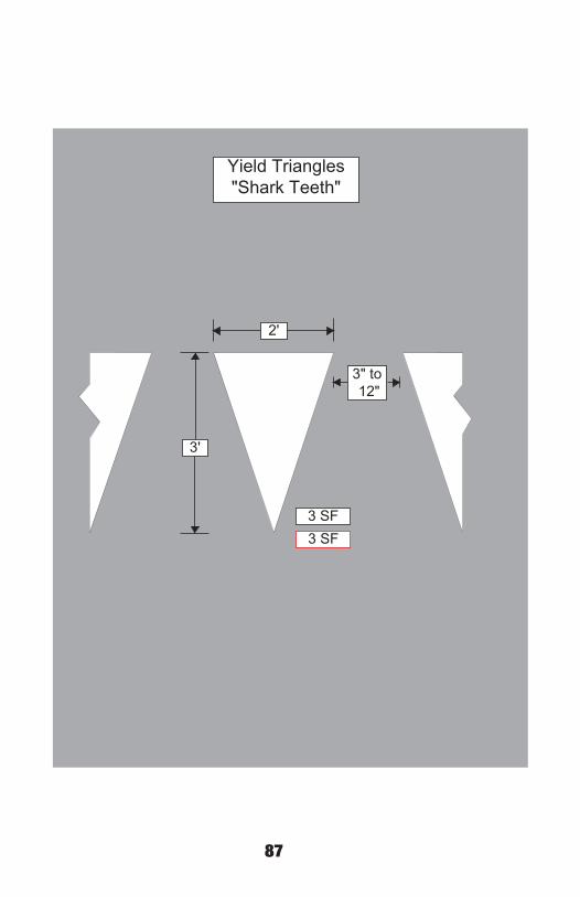
3 SF3 SF
2'
3'
3" to 12"
Yield Triangles"Shark Teeth"
8• •

88
24.3 SF24 SF
16'-6"
9'-6"
23'-6"
Interchange Ramp Arrow
40.2 SF40 SF
23'-6"
8'
Wrong Way Arrow
8• •
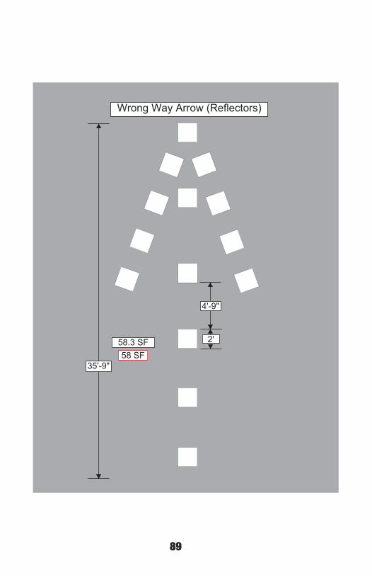
89
58.3 SF58 SF
35'-9"
2'
4'-9"
Wrong Way Arrow (Reflectors)
8• •
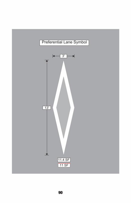
90
11.4 SF11 SF
3'
13'
Preferential Lane Symbol
8• •

91

92
9/19-0