Embed Size (px)
Citation preview

maintaining an anterior chamber with the cavitron unit Barrie Thrasher, M.D. Atlanta, Georgia
Maintenance of an anterior chamber using balanced salt solution (BSS) is not a new idea. However, using a Cavitron phacoemulsifier to force fluid into the anterior chamber while implanting a lens is somewhat novel.
We became interested in this technique for use with that occasional case of shallow chamber where air elevates the lens against the endothelium. Fluid infusion avoids lens-endothelium contact and allows, for the uninitiated, better visibility than air. Although fluid leaks out more rapidly than air, if continuous reinfusion of solution is perfonned using the Cavitron machine, the chamber can be maintained well.
Irrigating fluid
Fig. 1 (Thrasher). The normal set-up of the Cavitron unit.
Presented at the U.S. Intraocular Lens Symposium in Los Angeles, March 1978.
METHOD The Cavitron machine normally infuses fluid into
quite satifactory for us and we feel it has minimized pull of gravity (Fig. 1). Fig. 2 shows there~tructuring of the tubing set up to force fluid into the eye using the pump. The dial of the machine is set to "Standby" and position "2" of the foot pedal is used intermittently.
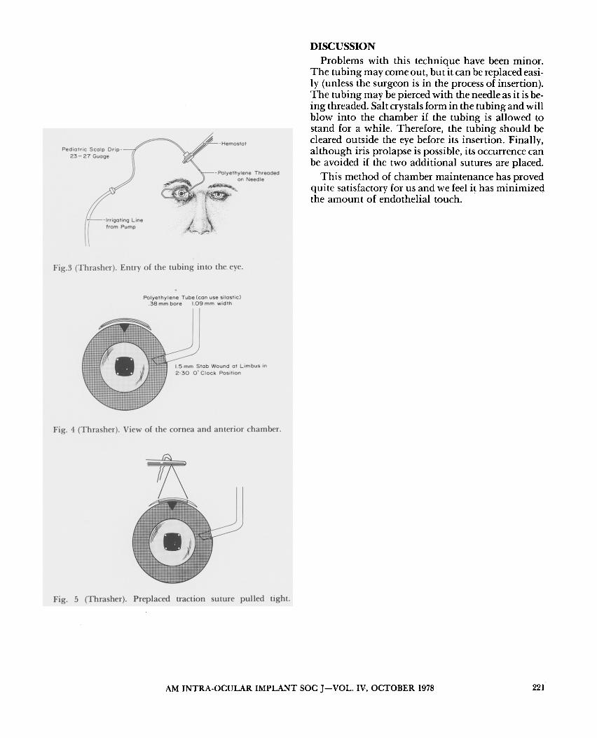
A pediatric scalp drip is attached to infusion tubing and the needle is threaded into lacrimal cannula polyethylene (or silastic) tubing (Fig. 3). The latter is bevel-cut. One mm of the tubing is then passed into the anterior chamber through a 2-0'clock limbal stab incision. This is made with a 52-Beaver Blade at the beginning of the procedure (Fig. 4).
Fig. 2 (Thrasher). Revision of fluid flow.
Irrigating -- fluid
Fig. 5 shows a traction suture of 10-0 Ethilon nylon which has been double armed and then pulled upon as the lens is reieased and the pump is activated. The wound shown in Fig. 5 is 6.5 mm. If a 1O.5-mm wound is used to express the nucleus, two additional sutures are placed laterally and tied first.
220 AM INTRA-OCULAR IMPLANT SOC .I-VOL. IV, OCTOBER 1978
Pediatric Scalp Drip-23-27 Guage
1-!---lrrioc,Iina Line from Pump
Fig.3 (Thrasher). Entry of the tubing into the eye.
Polyethylene Tube (can use silastic) .38 mm bore 1.09 mm width
1.5 mm Stab Wound at Limbus in 2:30 0 1 Clock Position
Fig. 4 (Thrasher). View of the cornea and anterior chamber.
Fig. 5 (Thrasher). Preplaced traction suture pulled tight.
DISCUSSION Problems with this technique have been minor.
The tubing may come out, but it can be replaced easily (unless the surgeon is in the process of insertion). The tubing may be pierced with the needle as it is being threaded. Salt crystals form in the tubing and will blow into the chamber if the tubing is allowed to stand for a while. Therefore, the tubing should be cleared outside the eye before its insertion. Finally, although iris prolapse is possible, its occurrence can be avoided if the two additional sutures are placed.
This method of chamber maintenance has proved quite satisfactory for us and we feel it has minimized the amount of endothelial touch.
AM INTRA-OCULAR IMPLANT SOC J-VOL. IV, OCTOBER 1978 221