Embed Size (px)
Citation preview
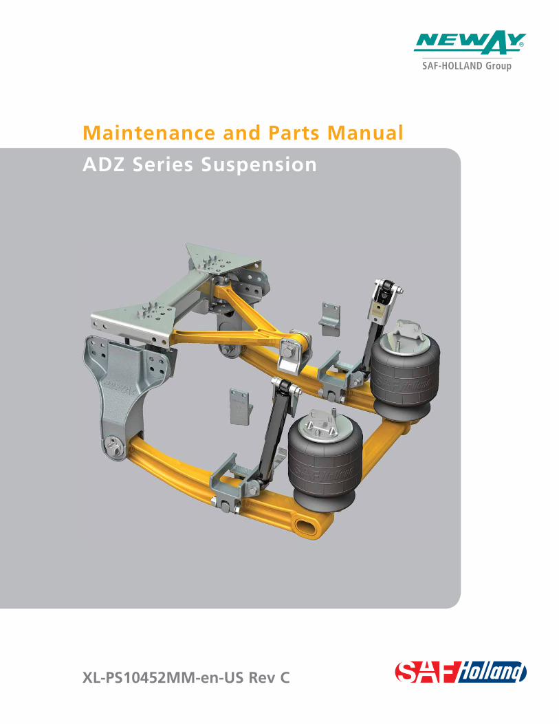
XL-PS10452MM-en-US Rev C
Maintenance and Parts Manual
ADZ Series Suspension


3XL-PS10452MM-en-US Rev C · 2013-04-03 · Amendments and errors reserved. © SAF-HOLLAND, Inc.
Contents
IntroductionThis manual provides you with information necessary for the care, maintenance, inspection, and safe operation of the SAF-HOLLAND Neway ADZ Series Air Suspension. The Neway ADZ Series Suspension is designed and engineered to provide trouble-free service. In the event of minor breakdown, such as a loss of air in the air springs, there are safety features designed into the suspension that will allow the vehicle to be driven CAUTIOUSLY at a slow speed, to the nearest service facility.
This suspension uses air delivered from the truck/tractor air system to pressurize the air springs and is controlled by either one or two height control valves. The height control valve regulates the air pressure required for varying loads and maintains the design ride height.
The Neway ADZ Series Suspensions are designed to be compatible with disc brake systems.
NOTE: For suspension components replacement contact SAF-HOLLAND Customer Service at 888-396-6501.
WarrantyRefer to the complete warranty for the country in which the product will be used. A copy of the written warranty can be found on the SAF-HOLLAND website (www.safholland.us).
Notes, Cautions, and WarningsYou must read and understand all of the safety procedures presented in this manual before starting any work on the suspension/axle.
NOTE: In the United States, workshop safety requirements are defined by federal and/or state Occupational Safety and Health Act or equivalent laws in other countries. This manual is written based on the assumption that OSHA or other applicable employee safety regulations are followed by the location where work is performed.
Proper tools must be used to perform the maintenance and repair procedures described in this manual. Some of these procedures require special tools.
Throughout this manual, you will notice the terms “NOTE”, “IMPORTANT”, “CAUTION”, and “WARNING” followed by important product information. So that you may better understand the manual, those terms are as follows:
NOTE: Includes additional information to enable accurate and easy performance of procedures.
IMPORTANT: Includes additional information that if not followed could lead to hindered product performance.
Used without the safety alert symbol, indicates a potentially hazardous situation which, if not avoided, could result in property damage.
Indicates a potentially hazardous situation which, if not avoided, could result in minor or moderate injury.
Indicates a potentially hazardous situation which, if not avoided, could result in death or serious injury.
Contents Page
Introduction ......................................................................... 3Warranty .............................................................................. 3Notes, Cautions, and Warnings ............................................. 3Section 1 – General Safety Instructions ................................ 4Section 2 – Model Identification & Serial Tag Information ..... 5Section 3 – Model Nomenclature ......................................... 5ADZ 123 Series Suspension – Exploded View ........................ 6ADZ 123 Series Suspension – Parts List ................................ 7ADZ 126 Series Suspension – Exploded View ........................ 8ADZ 126 Series Suspension – Parts List ................................ 9Section 4 – Service Repair Kits ........................................... 10Section 5 – Pre-Operation .................................................. 12Section 6 – Ride Height Adjustment ................................... 14
Contents Page
Section 7 – Axle Alignment ................................................ 15Section 8 – Changing Pinion Angle ..................................... 16
– Pinion Angle Reference Chart ........................... 19Section 9 – Air Spring Replacement .................................... 20Section 10 – Shock Absorber Replacement ......................... 21Section 11 – Axle Adapter Bar-Pin and Pivot Connection
Bushing Replacement ..................................... 22Section 12 – V-Rod Bushing Replacement ........................... 26Section 13 – Frame Bracket Replacement ........................... 29Section 14 – Torque Specifications ..................................... 32Section 15 – Routine Maintenance & Inspection ................. 33Section 16 – Troubleshooting ............................................. 34
XL-PS10452MM-en-US Rev C · 2013-04-03 · Amendments and errors reserved. © SAF-HOLLAND, Inc.
General Safety Instructions
4
1. General Safety Instructions
IMPORTANT: Read this manual before using this product. Keep this manual in a safe location for future reference.
Failure to follow the instructions and safety precautions in this manual could result in improper servicing or operation leading to component failure which if not avoided could result in death or serious injury.
Read and observe all Warning and Caution hazard alert messages in this publication. They provide information that can help prevent serious personal injury, damage to components, or both.
Failure to properly support the vehicle and/or suspension prior to commencing work could create a crush hazard which, if not avoided, could result in serious injury or death.
Please observe the following safety instructions in order to maintain the operational and road safety of your SAF-HOLLAND suspension:
1. Always be sure to chock the front tires prior to commencing work to prevent the vehicle from rolling forward or backward.
Failure to chock the front tires prior to commencing work may allow the vehicle to roll forward or backward which, if not avoided, could result in serious injury or death.
2. The air springs should always be operated with a static operating pressure between 80 psig (5.5 bars) and 100 psig (6.9 bars). The ideal static operating pressure of the air springs is 90 psig (6.2 bars).
Failure to operate the air springs with a proper static operating pressure could cause premature component failure and loss of vehicle control which, if not avoided, could result in death or serious injury.
3. In the event of an air loss, it is recommended to disconnect the HCV linkage to ensure all air springs are fully deflated. The vehicle can be temporarily operated and the load can be carried on the axle stops. In the event of inadequate air pressure, move the vehicle CAUTIOUSLY, at a slow speed, to the nearest repair facility. To deflate the air suspension, refer to procedures described in this manual. Before transporting the vehicle to a service center, check tire clearances. DO NOT operate the vehicle if any tire(s) is rubbing the vehicle.
Failure to maintain clearance between tires and the nearest point of contact on the suspension or vehicle could cause fire or loss of vehicle control which, if not avoided, could result in death or serious injury.
We highly recommend the use of only SAF-HOLLAND Original Parts.
A list of SAF-HOLLAND technical support locations to supply SAF-HOLLAND Original Parts can be found at www.safholland.us or you can contact SAF-HOLLAND Customer Service at 888-396-6501.
Updates to this manual will be published as necessary online at www.safholland.us.

XL-PS10452MM-en-US Rev C · 2013-04-03 · Amendments and errors reserved. © SAF-HOLLAND, Inc.
Model Information
5
Figure 2
Figure 3
Figure 1 2. Model Identification
A serial tag and model number tag are attached to the left and right ends of the transverse beam (lower control arm assembly) (Figure 1). The tags supply valuable information regarding the exact components used to manufacture the suspension (Figure 2).
NOTE: Depending upon chassis builder configuration, the model number tag may not call out the exact kit or parts list number. If so, the vehicle chassis builder will be able to identify the suspension model and its components using the vehicle’s VIN number.
IMPORTANT: Due to the custom built nature of each Neway ADZ application, having the exact parts list used by the chassis builder is critical in determining proper replacement components.
It is recommended that you determine your specific model number, record the information (Figure 3), and refer to it when obtaining information or replacement parts.
3. Model Nomenclature
IMPORTANT: This manual applies to the suspension model series listed below and for special orders of the same. It is very important to determine your specific model number, serial number, and parts list number. Record those numbers on this page, and refer to them when obtaining information or replacement parts.
Single Axle: Tandem Axle: Tridem Axle: ADZ-123 ADZ-246 ADZ-369 ADZ-124* ADZ-248* ADZ-126 ADZ-252 ADZ-378 ADZ-127* ADZ-254** Denotes special increased capacity for fire apparatus applications only with
SAF-HOLLAND Engineering approvals.
ADZ - X XX - 10
Air Drive
Number of Axles1 - Single2 - Tandem3 - Tridem
Rated Capacity (x1,000 lbs.)
Ride Height (Inches)
Write Important Suspension Data Here:
LCA Serial Number: ______________________
Model Number: _________________________
Parts List Number: _______________________
In Service Date: _________________________
SERIAL TAG
MODEL NUMBER TAG
SERIAL TAG
MODEL NUMBER TAG

XL-PS10452MM-en-US Rev C · 2013-04-03 · Amendments and errors reserved. © SAF-HOLLAND, Inc.
FOR 12" RIDE HEIGHT
ADZ 123 Series Suspension - Exploded View
6
39
38
14
9
8
13
1331
25
22A20
24
6 53 5
7
27B
4019
35
33
930
1113
15
1413
16
9
27A
32
33
34
109
34
37
2
2829
17
1819
21
20
26*
19
1
NOTE: Some of the ADZ components are available in Service Repair Kits found later in this Section.
41
2928
37 3636
2322B
20
42
4
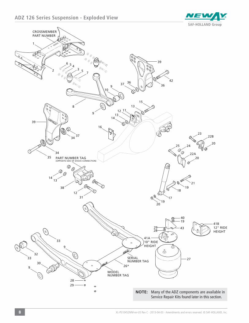
CROSSMEMBER PART NUMBER
39
36
12
PART NUMBER TAG (OPPOSITE SIDE OF SHOCK CONNECTION)
MODEL NUMBER TAG
SERIAL NUMBER TAG
XL-PS10452MM-en-US Rev C · 2013-04-03 · Amendments and errors reserved. © SAF-HOLLAND, Inc.
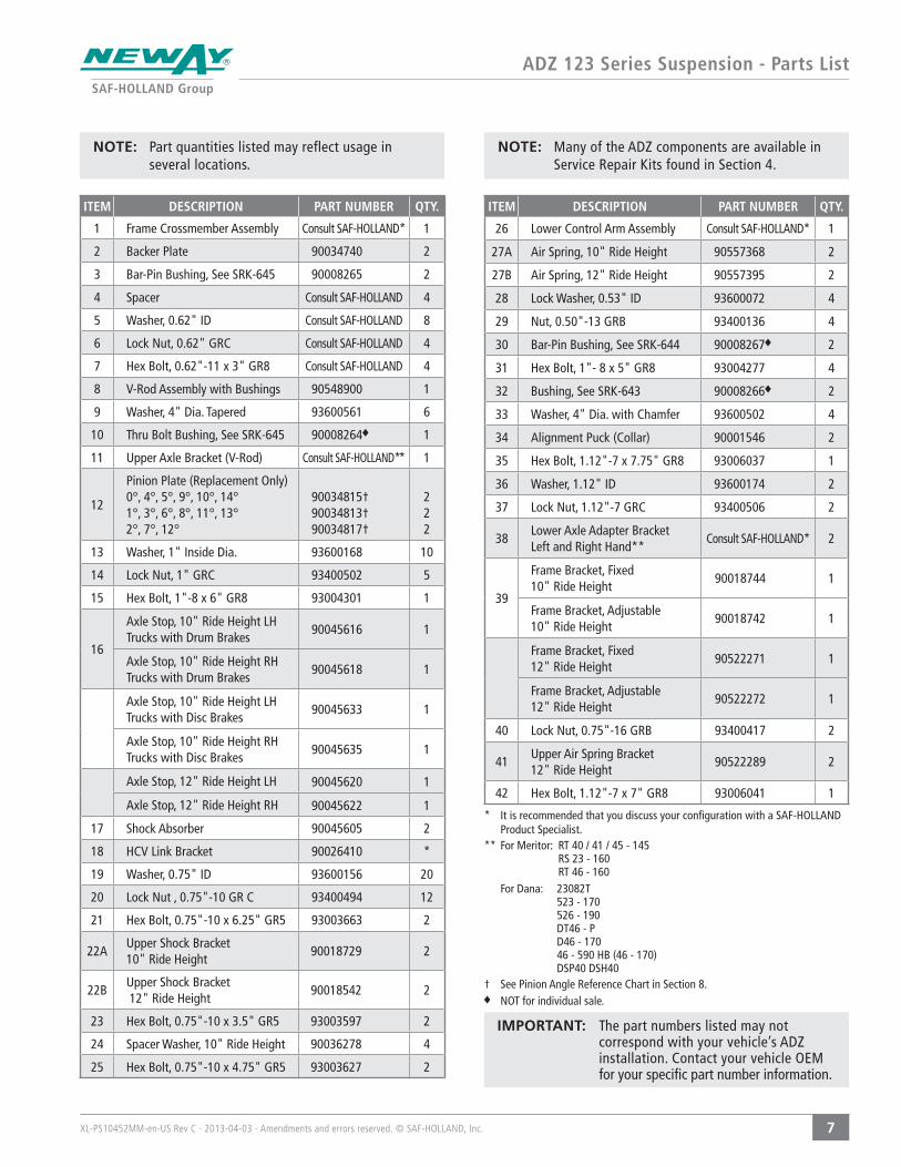
ADZ 123 Series Suspension - Parts List
7
ITEM DESCRIPTION PART NUMBER QTY.
1 Frame Crossmember Assembly Consult SAF-HOLLAND* 1
2 Backer Plate 90034740 2
3 Bar-Pin Bushing, See SRK-645 90008265 2
4 Spacer Consult SAF-HOLLAND 4
5 Washer, 0.62" ID Consult SAF-HOLLAND 8
6 Lock Nut, 0.62" GRC Consult SAF-HOLLAND 4
7 Hex Bolt, 0.62"-11 x 3" GR8 Consult SAF-HOLLAND 4
8 V-Rod Assembly with Bushings 90548900 1
9 Washer, 4" Dia. Tapered 93600561 6
10 Thru Bolt Bushing, See SRK-645 90008264 1
11 Upper Axle Bracket (V-Rod) Consult SAF-HOLLAND** 1
12
Pinion Plate (Replacement Only)0°, 4°, 5°, 9°, 10°, 14°1°, 3°, 6°, 8°, 11°, 13°2°, 7°, 12°
90034815†90034813†90034817†
222
13 Washer, 1" Inside Dia. 93600168 10
14 Lock Nut, 1" GRC 93400502 5
15 Hex Bolt, 1"-8 x 6" GR8 93004301 1
16
Axle Stop, 10" Ride Height LH Trucks with Drum Brakes
90045616 1
Axle Stop, 10" Ride Height RHTrucks with Drum Brakes
90045618 1
Axle Stop, 10" Ride Height LHTrucks with Disc Brakes
90045633 1
Axle Stop, 10" Ride Height RHTrucks with Disc Brakes
90045635 1
Axle Stop, 12" Ride Height LH 90045620 1
Axle Stop, 12" Ride Height RH 90045622 1
17 Shock Absorber 90045605 2
18 HCV Link Bracket 90026410 *
19 Washer, 0.75" ID 93600156 20
20 Lock Nut , 0.75"-10 GR C 93400494 12
21 Hex Bolt, 0.75"-10 x 6.25" GR5 93003663 2
22AUpper Shock Bracket 10" Ride Height
90018729 2
22BUpper Shock Bracket 12" Ride Height
90018542 2
23 Hex Bolt, 0.75"-10 x 3.5" GR5 93003597 2
24 Spacer Washer, 10" Ride Height 90036278 4
25 Hex Bolt, 0.75"-10 x 4.75" GR5 93003627 2
ITEM DESCRIPTION PART NUMBER QTY.
26 Lower Control Arm Assembly Consult SAF-HOLLAND* 1
27A Air Spring, 10" Ride Height 90557368 2
27B Air Spring, 12" Ride Height 90557395 2
28 Lock Washer, 0.53" ID 93600072 4
29 Nut, 0.50"-13 GRB 93400136 4
30 Bar-Pin Bushing, See SRK-644 90008267 2
31 Hex Bolt, 1"- 8 x 5" GR8 93004277 4
32 Bushing, See SRK-643 90008266 2
33 Washer, 4" Dia. with Chamfer 93600502 4
34 Alignment Puck (Collar) 90001546 2
35 Hex Bolt, 1.12"-7 x 7.75" GR8 93006037 1
36 Washer, 1.12" ID 93600174 2
37 Lock Nut, 1.12"-7 GRC 93400506 2
38Lower Axle Adapter Bracket Left and Right Hand**
Consult SAF-HOLLAND* 2
39
Frame Bracket, Fixed 10" Ride Height
90018744 1
Frame Bracket, Adjustable10" Ride Height
90018742 1
Frame Bracket, Fixed 12" Ride Height
90522271 1
Frame Bracket, Adjustable 12" Ride Height
90522272 1
40 Lock Nut, 0.75"-16 GRB 93400417 2
41Upper Air Spring Bracket 12" Ride Height
90522289 2
42 Hex Bolt, 1.12"-7 x 7" GR8 93006041 1
IMPORTANT: The part numbers listed may not correspond with your vehicle’s ADZ installation. Contact your vehicle OEM for your specific part number information.
* It is recommended that you discuss your configuration with a SAF-HOLLAND Product Specialist.
** For Meritor: RT 40 / 41 / 45 - 145 RS 23 - 160 RT 46 - 160
For Dana: 23082T 523 - 170 526 - 190 DT46 - P D46 - 170 46 - 590 HB (46 - 170) DSP40 DSH40
† See Pinion Angle Reference Chart in Section 8.NOT for individual sale.
NOTE: Many of the ADZ components are available in Service Repair Kits found in Section 4.
NOTE: Part quantities listed may reflect usage in several locations.
XL-PS10452MM-en-US Rev C · 2013-04-03 · Amendments and errors reserved. © SAF-HOLLAND, Inc.
ADZ 126 Series Suspension - Exploded View
8
39
38
14
9
8
13
1231
25
22A20
24
35
33
930
1113
15
1413
16
9
27
32
33
34
109
3437
2
2829
17
1819
21
20
26*
19
1
NOTE: Many of the ADZ components are available in Service Repair Kits found later in this section.
39
37 3636
2322B
20
4019
2928
41B12" RIDE HEIGHT
43
41A10" RIDE HEIGHT
42
6 53 5
7
4
CROSSMEMBER PART NUMBER
12
MODEL NUMBER TAG
SERIAL NUMBER TAG
PART NUMBER TAG (OPPOSITE SIDE OF SHOCK CONNECTION)
XL-PS10452MM-en-US Rev C · 2013-04-03 · Amendments and errors reserved. © SAF-HOLLAND, Inc.
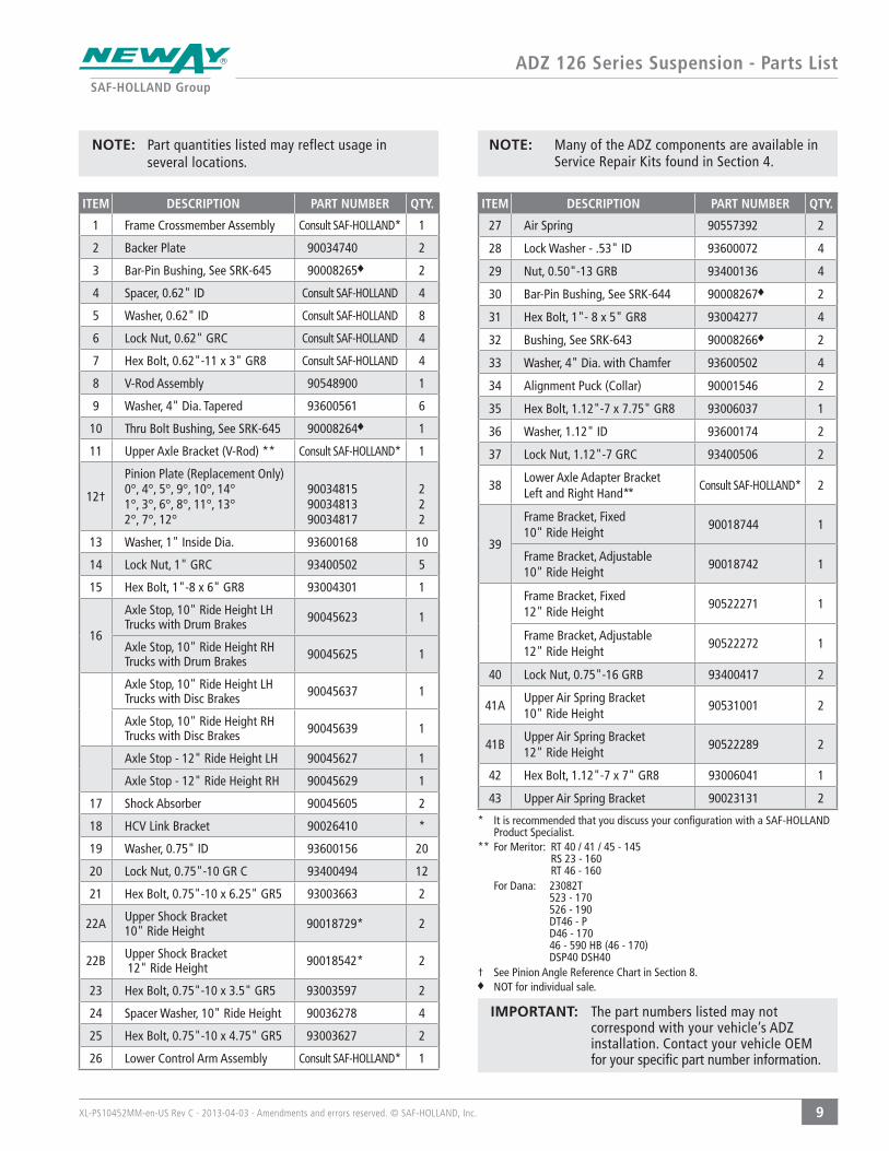
ADZ 126 Series Suspension - Parts List
9
ITEM DESCRIPTION PART NUMBER QTY.
1 Frame Crossmember Assembly Consult SAF-HOLLAND* 1
2 Backer Plate 90034740 2
3 Bar-Pin Bushing, See SRK-645 90008265 2
4 Spacer, 0.62" ID Consult SAF-HOLLAND 4
5 Washer, 0.62" ID Consult SAF-HOLLAND 8
6 Lock Nut, 0.62" GRC Consult SAF-HOLLAND 4
7 Hex Bolt, 0.62"-11 x 3" GR8 Consult SAF-HOLLAND 4
8 V-Rod Assembly 90548900 1
9 Washer, 4" Dia. Tapered 93600561 6
10 Thru Bolt Bushing, See SRK-645 90008264 1
11 Upper Axle Bracket (V-Rod) ** Consult SAF-HOLLAND* 1
12†
Pinion Plate (Replacement Only)0°, 4°, 5°, 9°, 10°, 14°1°, 3°, 6°, 8°, 11°, 13°2°, 7°, 12°
900348159003481390034817
222
13 Washer, 1" Inside Dia. 93600168 10
14 Lock Nut, 1" GRC 93400502 5
15 Hex Bolt, 1"-8 x 6" GR8 93004301 1
16
Axle Stop, 10" Ride Height LH Trucks with Drum Brakes 90045623 1
Axle Stop, 10" Ride Height RHTrucks with Drum Brakes 90045625 1
Axle Stop, 10" Ride Height LHTrucks with Disc Brakes 90045637 1
Axle Stop, 10" Ride Height RHTrucks with Disc Brakes 90045639 1
Axle Stop - 12" Ride Height LH 90045627 1
Axle Stop - 12" Ride Height RH 90045629 1
17 Shock Absorber 90045605 2
18 HCV Link Bracket 90026410 *
19 Washer, 0.75" ID 93600156 20
20 Lock Nut, 0.75"-10 GR C 93400494 12
21 Hex Bolt, 0.75"-10 x 6.25" GR5 93003663 2
22A Upper Shock Bracket 10" Ride Height 90018729* 2
22B Upper Shock Bracket 12" Ride Height 90018542* 2
23 Hex Bolt, 0.75"-10 x 3.5" GR5 93003597 2
24 Spacer Washer, 10" Ride Height 90036278 4
25 Hex Bolt, 0.75"-10 x 4.75" GR5 93003627 2
26 Lower Control Arm Assembly Consult SAF-HOLLAND* 1
ITEM DESCRIPTION PART NUMBER QTY.
27 Air Spring 90557392 2
28 Lock Washer - .53" ID 93600072 4
29 Nut, 0.50"-13 GRB 93400136 4
30 Bar-Pin Bushing, See SRK-644 90008267 2
31 Hex Bolt, 1"- 8 x 5" GR8 93004277 4
32 Bushing, See SRK-643 90008266 2
33 Washer, 4" Dia. with Chamfer 93600502 4
34 Alignment Puck (Collar) 90001546 2
35 Hex Bolt, 1.12"-7 x 7.75" GR8 93006037 1
36 Washer, 1.12" ID 93600174 2
37 Lock Nut, 1.12"-7 GRC 93400506 2
38Lower Axle Adapter Bracket Left and Right Hand**
Consult SAF-HOLLAND* 2
39
Frame Bracket, Fixed 10" Ride Height
90018744 1
Frame Bracket, Adjustable 10" Ride Height
90018742 1
Frame Bracket, Fixed 12" Ride Height
90522271 1
Frame Bracket, Adjustable 12" Ride Height
90522272 1
40 Lock Nut, 0.75"-16 GRB 93400417 2
41AUpper Air Spring Bracket 10" Ride Height
90531001 2
41BUpper Air Spring Bracket 12" Ride Height
90522289 2
42 Hex Bolt, 1.12"-7 x 7" GR8 93006041 1
43 Upper Air Spring Bracket 90023131 2
* It is recommended that you discuss your configuration with a SAF-HOLLAND Product Specialist.
** For Meritor: RT 40 / 41 / 45 - 145 RS 23 - 160 RT 46 - 160
For Dana: 23082T 523 - 170 526 - 190 DT46 - P D46 - 170 46 - 590 HB (46 - 170) DSP40 DSH40
† See Pinion Angle Reference Chart in Section 8.NOT for individual sale.
NOTE: Many of the ADZ components are available in Service Repair Kits found in Section 4.
NOTE: Part quantities listed may reflect usage in several locations.
IMPORTANT: The part numbers listed may not correspond with your vehicle’s ADZ installation. Contact your vehicle OEM for your specific part number information.

XL-PS10452MM-en-US Rev C · 2013-04-03 · Amendments and errors reserved. © SAF-HOLLAND, Inc.
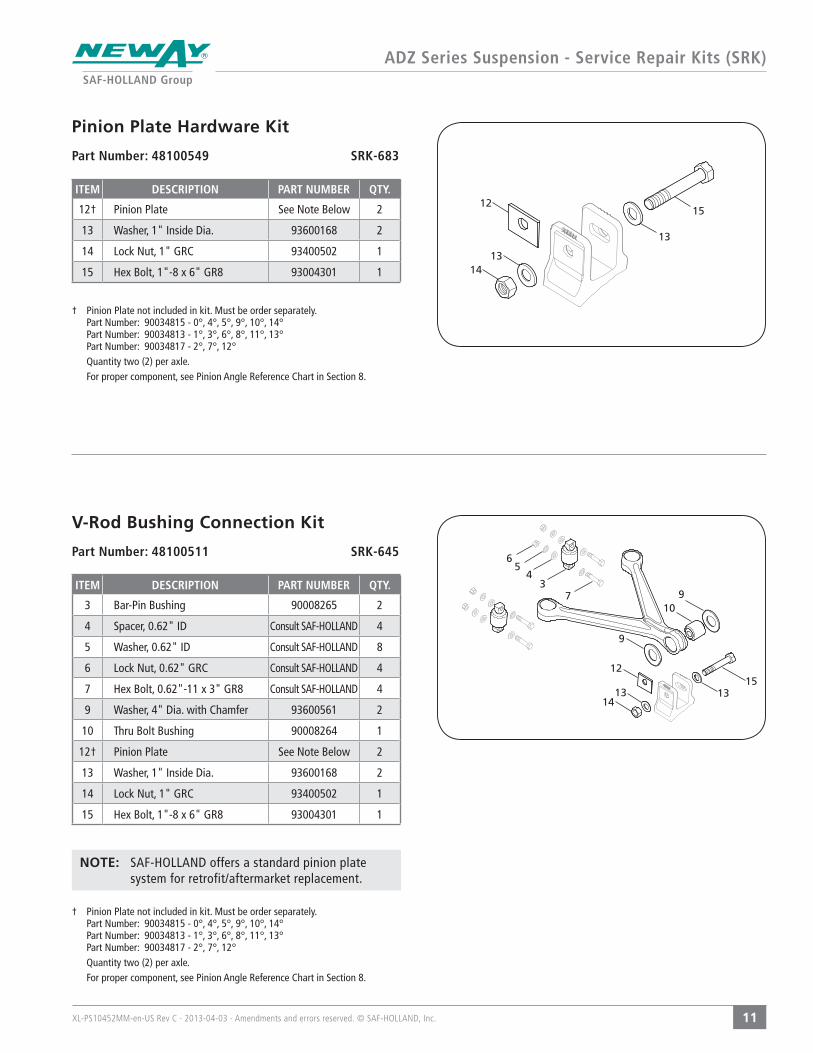
ADZ Series Suspension - Service Repair Kits (SRK)
10
ITEM DESCRIPTION PART NUMBER QTY.
32 Bushing 90008266 2
33 Washer, 4" Dia. with Chamfer 93600502 4
34 Alignment Puck (Collar) 90001546 2
35 Hex Bolt, 1.12"-7 x 7.75" GR8 93006037 1
36 Washer, 1.12" ID 93600174 3
37 Lock Nut, 1.12"-7 GRC 93400506 2
42 Hex Bolt, 1.12"- 7 x 7" GR8 93006041 1
4. Service Repair Kits
Front Pivot Bushing Connection Kit
Part Number: 48100509 SRK-643
3332
33
4236
34
37
35
3436
ITEM DESCRIPTION PART NUMBER QTY.
30 Bar-Pin Bushing 90008267 2
9 Washer, 4"Dia. with Chamfer 93600561 4
13 Washer, 1" Inside Dia. 93600168 8
14 Lock Nut, 1" GRC 93400502 4
31 Hex Bolt, 1"- 8 x 5" GR8 93004277 4
Axle Bar-Pin Bushing Connection Kit
Part Number: 48100510 SRK-644
9
30
14
1331
9
13
37
XL-PS10452MM-en-US Rev C · 2013-04-03 · Amendments and errors reserved. © SAF-HOLLAND, Inc.
ADZ Series Suspension - Service Repair Kits (SRK)
11
NOTE: SAF-HOLLAND offers a standard pinion plate system for retrofit/aftermarket replacement.
ITEM DESCRIPTION PART NUMBER QTY.
3 Bar-Pin Bushing 90008265 2
4 Spacer, 0.62" ID Consult SAF-HOLLAND 4
5 Washer, 0.62" ID Consult SAF-HOLLAND 8
6 Lock Nut, 0.62" GRC Consult SAF-HOLLAND 4
7 Hex Bolt, 0.62"-11 x 3" GR8 Consult SAF-HOLLAND 4
9 Washer, 4" Dia. with Chamfer 93600561 2
10 Thru Bolt Bushing 90008264 1
12† Pinion Plate See Note Below 2
13 Washer, 1" Inside Dia. 93600168 2
14 Lock Nut, 1" GRC 93400502 1
15 Hex Bolt, 1"-8 x 6" GR8 93004301 1
V-Rod Bushing Connection Kit
Part Number: 48100511 SRK-645 65
37
10
1513
9
1413
12
4
† Pinion Plate not included in kit. Must be order separately. Part Number: 90034815 - 0°, 4°, 5°, 9°, 10°, 14° Part Number: 90034813 - 1°, 3°, 6°, 8°, 11°, 13° Part Number: 90034817 - 2°, 7°, 12°
Quantity two (2) per axle. For proper component, see Pinion Angle Reference Chart in Section 8.
9
1413
12
13
15
ITEM DESCRIPTION PART NUMBER QTY.
12† Pinion Plate See Note Below 2
13 Washer, 1" Inside Dia. 93600168 2
14 Lock Nut, 1" GRC 93400502 1
15 Hex Bolt, 1"-8 x 6" GR8 93004301 1
Pinion Plate Hardware Kit
Part Number: 48100549 SRK-683
† Pinion Plate not included in kit. Must be order separately. Part Number: 90034815 - 0°, 4°, 5°, 9°, 10°, 14° Part Number: 90034813 - 1°, 3°, 6°, 8°, 11°, 13° Part Number: 90034817 - 2°, 7°, 12°
Quantity two (2) per axle. For proper component, see Pinion Angle Reference Chart in Section 8.
XL-PS10452MM-en-US Rev C · 2013-04-03 · Amendments and errors reserved. © SAF-HOLLAND, Inc.
Pre-Operation
12
Figure 5
Figure 6
Figure 4 5. Pre-Operation
1. With the vehicle on a level surface, build air pressure above 70 psig (4.83 bars).
2. Shut off the vehicle and visually check all air control system fittings for air leaks by applying a soapy water solution and checking for bubbles at all air connections and fittings. Check the air springs for equal firmness.
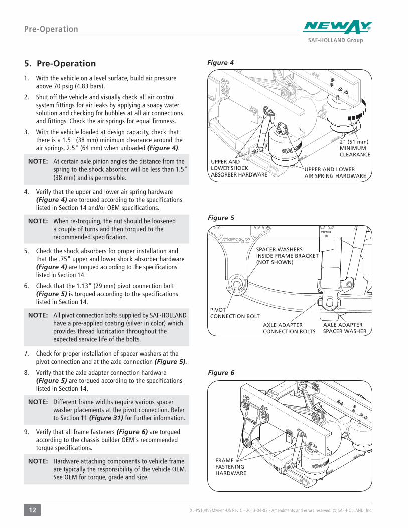
3. With the vehicle loaded at design capacity, check that there is a 1.5" (38 mm) minimum clearance around the air springs, 2.5" (64 mm) when unloaded (Figure 4).
NOTE: At certain axle pinion angles the distance from the spring to the shock absorber will be less than 1.5" (38 mm) and is permissible.
4. Verify that the upper and lower air spring hardware (Figure 4) are torqued according to the specifications listed in Section 14 and/or OEM specifications.
NOTE: When re-torquing, the nut should be loosened a couple of turns and then torqued to the recommended specification.
5. Check the shock absorbers for proper installation and that the .75" upper and lower shock absorber hardware (Figure 4) are torqued according to the specifications listed in Section 14.
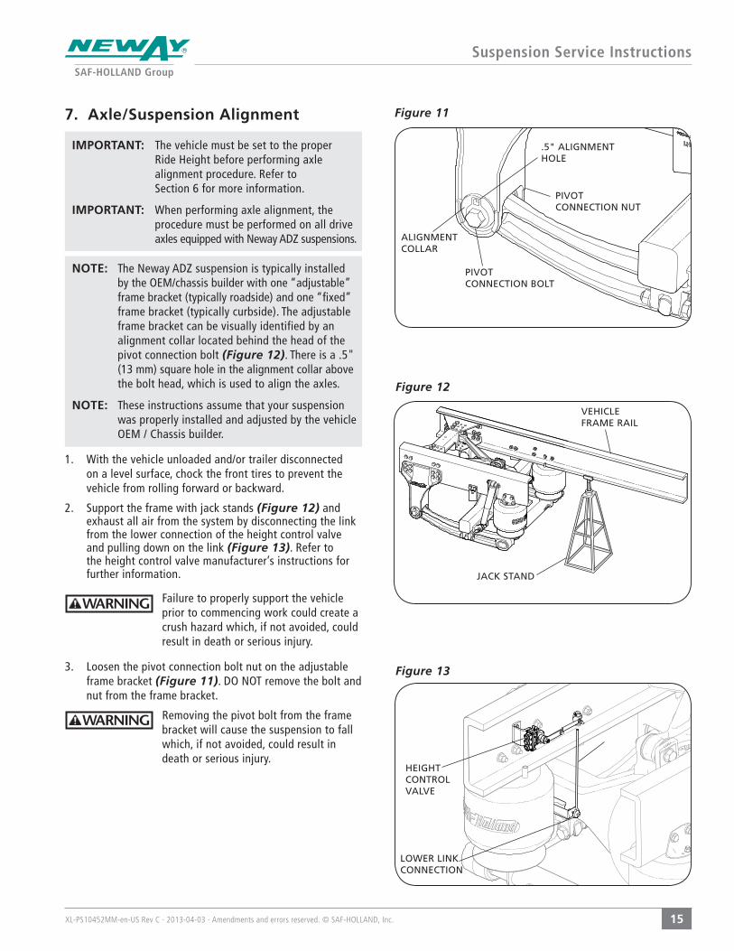
6. Check that the 1.13" (29 mm) pivot connection bolt (Figure 5) is torqued according to the specifications listed in Section 14.
NOTE: All pivot connection bolts supplied by SAF-HOLLAND have a pre-applied coating (silver in color) which provides thread lubrication throughout the expected service life of the bolts.
7. Check for proper installation of spacer washers at the pivot connection and at the axle connection (Figure 5).
8. Verify that the axle adapter connection hardware (Figure 5) are torqued according to the specifications listed in Section 14.
NOTE: Different frame widths require various spacer washer placements at the pivot connection. Refer to Section 11 (Figure 31) for further information.
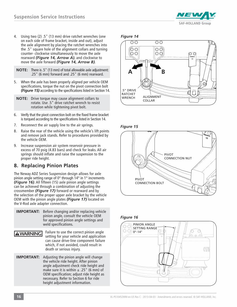
9. Verify that all frame fasteners (Figure 6) are torqued according to the chassis builder OEM’s recommended torque specifications.
NOTE: Hardware attaching components to vehicle frame are typically the responsibility of the vehicle OEM. See OEM for torque, grade and size.
UPPER AND LOWERAIR SPRING HARDWARE
2" (51 mm)MINIMUM CLEARANCE
UPPER AND LOWER SHOCK ABSORBER HARDWARE
SPACER WASHERS INSIDE FRAME BRACKET (NOT SHOWN)
PIVOT CONNECTION BOLT
AXLE ADAPTER CONNECTION BOLTS
AXLE ADAPTER SPACER WASHER
FRAME FASTENING HARDWARE

XL-PS10452MM-en-US Rev C · 2013-04-03 · Amendments and errors reserved. © SAF-HOLLAND, Inc.
Pre-Operation
13
Figure 9
Figure 7 10. The suspension ride height should be within ± .25" (6 mm) of the recommended design height. See Section 6 for further ride height information.
11. Weld-On Axle Adapter Bracket (Figure 7): The welds connecting the axle adapter brackets to the axle must be to the axle manufacturer’s or vehicle OEM’s specifications.
12. Check that the axle pinion angle (axle tilt) is within the chassis builder’s specifications. Refer to (Figure 8) for definition of pinion angle.
13. Ensure that SAF-HOLLAND axle stops are properly installed (Figure 9).
Failure to properly install axle stops could result in component failure which, if not avoided, could result in minor or moderate injury.
14. Check the alignment of the suspension per vehicle OEM instructions. If realignment is necessary, refer to the alignment procedures described in Section 6.
WELD-ONAXLE ADAPTER
AXLE STOP
Figure 8
PINION ANGLE SETTING RANGE 0°-14°

XL-PS10452MM-en-US Rev C · 2013-04-03 · Amendments and errors reserved. © SAF-HOLLAND, Inc.
Suspension Service Instructions
14
AB
Figure 10 6. Ride Height Adjustment
Proper suspension ride height should be within ± .25" (6 mm) of the specified ride height.
NOTE: The specified ride height can be found in the model number (Example: Model ADZ-123-10, the ride height is 10").
To check the current ride height of your suspension use the following steps:
1. Drive the vehicle forward in a straight line for at least two (2) vehicle lengths to release any bushing wind up.
2. With the vehicle unloaded and/or trailer disconnected on a level surface, chock the front tires to prevent the vehicle from rolling forward or backward.
3. Pressurize the air system with a constant supply of air in excess of 70 psig (4.8 bars) and check that all air springs properly inflate and raise the suspension to the proper ride height.
4. Measure the distance from the bottom of the frame rail to the ground (Figure 10 - Arrow A).
5. Measure the distance from the center of the wheel to the ground (Figure 10 - Arrow B).
6. Subtract the measurement found in Step 5 from the measurement found in Step 4 to determine the current ride height of your suspension.
Example: The bottom of the frame rail to the ground measures 30" (762 mm) (A). The center of the wheel to the ground measures 20" (508 mm) (B).
A (30") minus B (20") = Ride Height (10.0")
Current suspension ride height = 10.0"
IMPORTANT: If the measured ride height is not within ± .25" (6 mm) it must be adjusted using the height control valve. Refer to the height control valve manufacturer’s instructions for adjustment procedures.
NOTE: If proper ride height is not obtained or air springs do not inflate properly; check air pressure and check for proper piping in accordance with the truck manufacturer’s procedures and owner’s manual then repeat above steps. If proper ride height still cannot be obtained, contact vehicle OEM for assistance.
RIDE HEIGHT
XL-PS10452MM-en-US Rev C · 2013-04-03 · Amendments and errors reserved. © SAF-HOLLAND, Inc.
Suspension Service Instructions
15
Figure 12
Figure 117. Axle/Suspension Alignment
IMPORTANT: The vehicle must be set to the proper Ride Height before performing axle alignment procedure. Refer to Section 6 for more information.
IMPORTANT: When performing axle alignment, the procedure must be performed on all drive axles equipped with Neway ADZ suspensions.
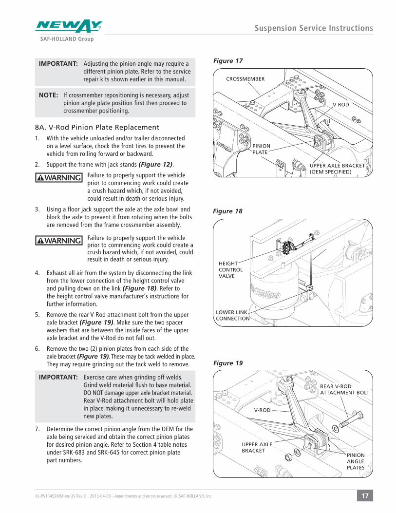
NOTE: The Neway ADZ suspension is typically installed by the OEM/chassis builder with one “adjustable” frame bracket (typically roadside) and one “fixed” frame bracket (typically curbside). The adjustable frame bracket can be visually identified by an alignment collar located behind the head of the pivot connection bolt (Figure 12). There is a .5" (13 mm) square hole in the alignment collar above the bolt head, which is used to align the axles.
NOTE: These instructions assume that your suspension was properly installed and adjusted by the vehicle OEM / Chassis builder.
1. With the vehicle unloaded and/or trailer disconnected on a level surface, chock the front tires to prevent the vehicle from rolling forward or backward.
2. Support the frame with jack stands (Figure 12) and exhaust all air from the system by disconnecting the link from the lower connection of the height control valve and pulling down on the link (Figure 13). Refer to the height control valve manufacturer’s instructions for further information.
Failure to properly support the vehicle prior to commencing work could create a crush hazard which, if not avoided, could result in death or serious injury.
3. Loosen the pivot connection bolt nut on the adjustable frame bracket (Figure 11). DO NOT remove the bolt and nut from the frame bracket.
Removing the pivot bolt from the frame bracket will cause the suspension to fall which, if not avoided, could result in death or serious injury.
PIVOT CONNECTION BOLT
ALIGNMENT COLLAR
.5" ALIGNMENT HOLE
PIVOT CONNECTION NUT
VEHICLE FRAME RAIL
JACK STAND
Figure 13
HEIGHT CONTROL VALVE
LOWER LINK CONNECTION
XL-PS10452MM-en-US Rev C · 2013-04-03 · Amendments and errors reserved. © SAF-HOLLAND, Inc.
Suspension Service Instructions
16
Figure 15
Figure 16
4. Using two (2) .5" (13 mm) drive ratchet wrenches (one on each side of frame bracket, inside and out), adjust the axle alignment by placing the ratchet wrenches into the .5" square hole of the alignment collars and turning counter- clockwise simultaneously to move the axle rearward (Figure 14, Arrow A), and clockwise to move the axle forward (Figure 14, Arrow B).
NOTE: There is .5" (13 mm) of total allowable axle adjustment: .25" (6 mm) forward and .25" (6 mm) rearward.
5. When the axle has been properly aligned per vehicle OEM specifications, torque the nut on the pivot connection bolt (Figure 15) according to the specifications listed in Section 14.
NOTE: Drive torque may cause alignment collars to rotate. Use .5" drive ratchet wrench to resist rotation while tightening pivot bolt.
6. Verify that the pivot connection bolt on the fixed frame bracket is torqued according to the specifications listed in Section 14.
7. Reconnect the air supply line to the air springs.
8. Raise the rear of the vehicle using the vehicle’s lift points and remove jack stands. Refer to procedures provided by the vehicle OEM.
9. Increase suspension air system reservoir pressure in excess of 70 psig (4.83 bars) and check for leaks. All air springs should inflate and raise the suspension to the proper ride height.
8. Replacing Pinion Plates
The Neway ADZ Series Suspension design allows for axle pinion angle setting range of 0° through 14° in 1° increments (Figure 16). All fifteen (15) axle pinion angle settings can be achieved through a combination of adjusting the crossmember (Figure 17) forward or rearward and by the selection of the proper upper axle bracket by the vehicle OEM with the pinion angle plates (Figure 17) located on the V-Rod axle adapter connection.
IMPORTANT: Before changing and/or replacing vehicle pinion angle, consult the vehicle OEM for approved pinion angle settings and weld specifications.
Failure to use the correct pinion angle setting for your vehicle and application can cause drive-line component failure which, if not avoided, could result in death or serious injury.
IMPORTANT: Adjusting the pinion angle will change the vehicle ride height. After pinion angle adjustment check ride height and make sure it is within ± .25" (6 mm) of OEM specification; adjust ride height as necessary. Refer to Section 6 for ride height adjustment information.
PINION ANGLE SETTING RANGE 0°-14°
PIVOT CONNECTION BOLT
PIVOT CONNECTION NUT
A B
Figure 14
.5" DRIVE RATCHET WRENCH ALIGNMENT
COLLAR
XL-PS10452MM-en-US Rev C · 2013-04-03 · Amendments and errors reserved. © SAF-HOLLAND, Inc.
Suspension Service Instructions
17
Figure 17 IMPORTANT: Adjusting the pinion angle may require a different pinion plate. Refer to the service repair kits shown earlier in this manual.
NOTE: If crossmember repositioning is necessary, adjust pinion angle plate position first then proceed to crossmember positioning.
8A. V-Rod Pinion Plate Replacement
1. With the vehicle unloaded and/or trailer disconnected on a level surface, chock the front tires to prevent the vehicle from rolling forward or backward.
2. Support the frame with jack stands (Figure 12).
Failure to properly support the vehicle prior to commencing work could create a crush hazard which, if not avoided, could result in death or serious injury.
3. Using a floor jack support the axle at the axle bowl and block the axle to prevent it from rotating when the bolts are removed from the frame crossmember assembly.
Failure to properly support the vehicle prior to commencing work could create a crush hazard which, if not avoided, could result in death or serious injury.
4. Exhaust all air from the system by disconnecting the link from the lower connection of the height control valve and pulling down on the link (Figure 18). Refer to the height control valve manufacturer’s instructions for further information.
5. Remove the rear V-Rod attachment bolt from the upper axle bracket (Figure 19). Make sure the two spacer washers that are between the inside faces of the upper axle bracket and the V-Rod do not fall out.
6. Remove the two (2) pinion plates from each side of the axle bracket (Figure 19). These may be tack welded in place. They may require grinding out the tack weld to remove.
IMPORTANT: Exercise care when grinding off welds. Grind weld material flush to base material. DO NOT damage upper axle bracket material. Rear V-Rod attachment bolt will hold plate in place making it unnecessary to re-weld new plates.
7. Determine the correct pinion angle from the OEM for the axle being serviced and obtain the correct pinion plates for desired pinion angle. Refer to Section 4 table notes under SRK-683 and SRK-645 for correct pinion plate part numbers.
CROSSMEMBER
V-ROD
PINION PLATE
UPPER AXLE BRACKET (OEM SPECIFIED)
Figure 18
HEIGHT CONTROL VALVE
LOWER LINK CONNECTION
Figure 19
REAR V-ROD ATTACHMENT BOLT
PINION ANGLE PLATES
UPPER AXLE BRACKET
V-ROD
XL-PS10452MM-en-US Rev C · 2013-04-03 · Amendments and errors reserved. © SAF-HOLLAND, Inc.
Suspension Service Instructions
18
Figure 22
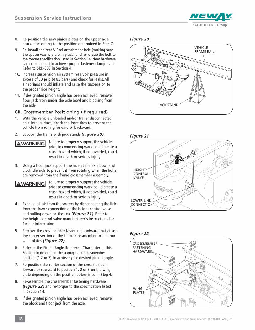
8. Re-position the new pinion plates on the upper axle bracket according to the position determined in Step 7.
9. Re-install the rear V-Rod attachment bolt (making sure the spacer washers are in place) and re-torque the bolt to the torque specification listed in Section 14. New hardware is recommended to achieve proper fastener clamp load. Refer to SRK-683 in Section 4.
10. Increase suspension air system reservoir pressure in excess of 70 psig (4.83 bars) and check for leaks. All air springs should inflate and raise the suspension to the proper ride height.
11. If designated pinion angle has been achieved, remove floor jack from under the axle bowl and blocking from the axle.
8B. Crossmember Positioning (if required)1. With the vehicle unloaded and/or trailer disconnected
on a level surface, chock the front tires to prevent the vehicle from rolling forward or backward.
2. Support the frame with jack stands (Figure 20).
Failure to properly support the vehicle prior to commencing work could create a crush hazard which, if not avoided, could result in death or serious injury.
3. Using a floor jack support the axle at the axle bowl and block the axle to prevent it from rotating when the bolts are removed from the frame crossmember assembly.
Failure to properly support the vehicle prior to commencing work could create a crush hazard which, if not avoided, could result in death or serious injury.
4. Exhaust all air from the system by disconnecting the link from the lower connection of the height control valve and pulling down on the link (Figure 21). Refer to the height control valve manufacturer’s instructions for further information.
5. Remove the crossmember fastening hardware that attach the center section of the frame crossmember to the four wing plates (Figure 22).
6. Refer to the Pinion Angle Reference Chart later in this Section to determine the appropriate crossmember position (1,2 or 3) to achieve your desired pinion angle.
7. Re-position the center section of the crossmember forward or rearward to position 1, 2 or 3 on the wing plate depending on the position determined in Step 4.
8. Re-assemble the crossmember fastening hardware (Figure 22) and re-torque to the specification listed in Section 14.
9. If designated pinion angle has been achieved, remove the block and floor jack from the axle.
CROSSMEMBER FASTENING HARDWARE
WING PLATES
Figure 20
VEHICLE FRAME RAIL
JACK STAND
Figure 21
HEIGHT CONTROL VALVE
LOWER LINK CONNECTION
XL-PS10452MM-en-US Rev C · 2013-04-03 · Amendments and errors reserved. © SAF-HOLLAND, Inc.
Pinion Angle Reference Chart
19
VEHICLE FRONT
2
2
3
3
3
PINION PLATENOTCH AT SLOT 1
AXLE ADAPTER BRACKET
4° ANGLE CROSSMEMBER IN
POSITION 1
9° ANGLE CROSSMEMBER IN
POSITION 2
14° ANGLE CROSSMEMBER IN
POSITION 3
1 1 12 23 3
PINION PLATE ORIENTATION
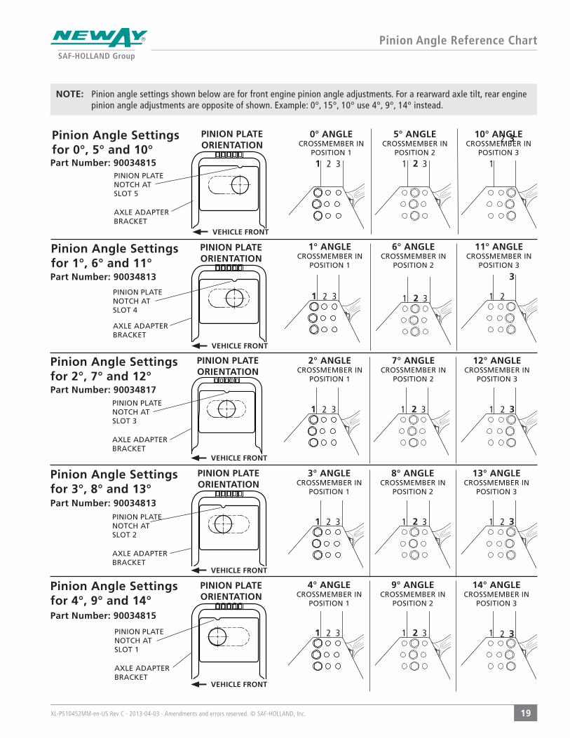
Pinion Angle Settings for 4°, 9° and 14°Part Number: 90034815
PINION PLATENOTCH AT SLOT 2
AXLE ADAPTER BRACKET
VEHICLE FRONT
3° ANGLE CROSSMEMBER IN
POSITION 1
8° ANGLE CROSSMEMBER IN
POSITION 2
13° ANGLE CROSSMEMBER IN
POSITION 3
1 1 12 2 23 3 3
PINION PLATE ORIENTATION
Pinion Angle Settings for 3°, 8° and 13°Part Number: 90034813
PINION PLATENOTCH AT SLOT 3
AXLE ADAPTER BRACKET
VEHICLE FRONT
2° ANGLE CROSSMEMBER IN
POSITION 1
7° ANGLE CROSSMEMBER IN
POSITION 2
12° ANGLE CROSSMEMBER IN
POSITION 3
1 1 12 2 23 3 3
PINION PLATE ORIENTATION
Pinion Angle Settings for 2°, 7° and 12°Part Number: 90034817
PINION PLATENOTCH AT SLOT 4
AXLE ADAPTER BRACKET
VEHICLE FRONT
1° ANGLE CROSSMEMBER IN
POSITION 1
6° ANGLE CROSSMEMBER IN
POSITION 2
11° ANGLE CROSSMEMBER IN
POSITION 3
1 1 12 2 23 3
PINION PLATE ORIENTATION
Pinion Angle Settings for 1°, 6° and 11°Part Number: 90034813
PINION PLATENOTCH AT SLOT 5
AXLE ADAPTER BRACKET
VEHICLE FRONT
0° ANGLE CROSSMEMBER IN
POSITION 1
5° ANGLE CROSSMEMBER IN
POSITION 2
10° ANGLE CROSSMEMBER IN
POSITION 3
1 1 12 23 3
PINION PLATE ORIENTATION
Pinion Angle Settings for 0°, 5° and 10°Part Number: 90034815
NOTE: Pinion angle settings shown below are for front engine pinion angle adjustments. For a rearward axle tilt, rear engine pinion angle adjustments are opposite of shown. Example: 0°, 15°, 10° use 4°, 9°, 14° instead.
XL-PS10452MM-en-US Rev C · 2013-04-03 · Amendments and errors reserved. © SAF-HOLLAND, Inc.
Component Replacement Instructions
20
Figure 24
Figure 25
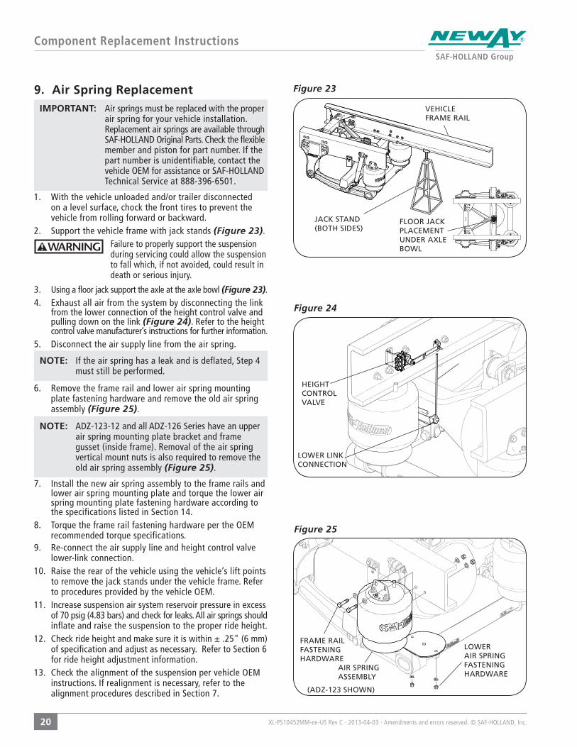
Figure 23 9. Air Spring ReplacementIMPORTANT: Air springs must be replaced with the proper
air spring for your vehicle installation. Replacement air springs are available through SAF-HOLLAND Original Parts. Check the flexible member and piston for part number. If the part number is unidentifiable, contact the vehicle OEM for assistance or SAF-HOLLAND Technical Service at 888-396-6501.
1. With the vehicle unloaded and/or trailer disconnected on a level surface, chock the front tires to prevent the vehicle from rolling forward or backward.
2. Support the vehicle frame with jack stands (Figure 23). Failure to properly support the suspension during servicing could allow the suspension to fall which, if not avoided, could result in death or serious injury.
3. Using a floor jack support the axle at the axle bowl (Figure 23).4. Exhaust all air from the system by disconnecting the link
from the lower connection of the height control valve and pulling down on the link (Figure 24). Refer to the height control valve manufacturer’s instructions for further information.
5. Disconnect the air supply line from the air spring.
NOTE: If the air spring has a leak and is deflated, Step 4 must still be performed.
6. Remove the frame rail and lower air spring mounting plate fastening hardware and remove the old air spring assembly (Figure 25).
NOTE: ADZ-123-12 and all ADZ-126 Series have an upper air spring mounting plate bracket and frame gusset (inside frame). Removal of the air spring vertical mount nuts is also required to remove the old air spring assembly (Figure 25).
7. Install the new air spring assembly to the frame rails and lower air spring mounting plate and torque the lower air spring mounting plate fastening hardware according to the specifications listed in Section 14.
8. Torque the frame rail fastening hardware per the OEM recommended torque specifications.
9. Re-connect the air supply line and height control valve lower-link connection.
10. Raise the rear of the vehicle using the vehicle’s lift points to remove the jack stands under the vehicle frame. Refer to procedures provided by the vehicle OEM.
11. Increase suspension air system reservoir pressure in excess of 70 psig (4.83 bars) and check for leaks. All air springs should inflate and raise the suspension to the proper ride height.
12. Check ride height and make sure it is within ± .25" (6 mm) of specification and adjust as necessary. Refer to Section 6 for ride height adjustment information.
13. Check the alignment of the suspension per vehicle OEM instructions. If realignment is necessary, refer to the alignment procedures described in Section 7.
FLOOR JACK PLACEMENT UNDER AXLE BOWL
VEHICLE FRAME RAIL
JACK STAND(BOTH SIDES)
FRAME RAIL FASTENING HARDWARE
(ADZ-123 SHOWN)
AIR SPRING ASSEMBLY
LOWER AIR SPRING FASTENING HARDWARE
HEIGHT CONTROL VALVE
LOWER LINK CONNECTION
XL-PS10452MM-en-US Rev C · 2013-04-03 · Amendments and errors reserved. © SAF-HOLLAND, Inc.
Component Replacement Instructions
21
Figure 27
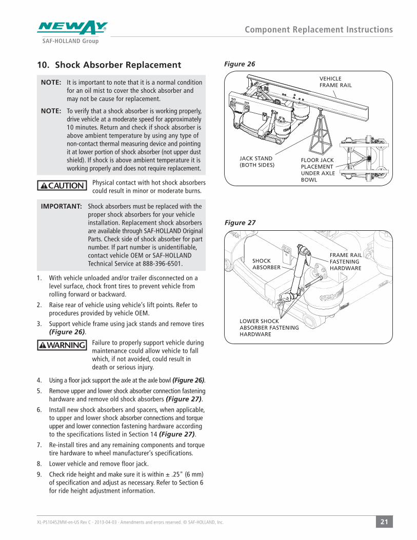
10. Shock Absorber Replacement
NOTE: It is important to note that it is a normal condition for an oil mist to cover the shock absorber and may not be cause for replacement.
NOTE: To verify that a shock absorber is working properly, drive vehicle at a moderate speed for approximately 10 minutes. Return and check if shock absorber is above ambient temperature by using any type of non-contact thermal measuring device and pointing it at lower portion of shock absorber (not upper dust shield). If shock is above ambient temperature it is working properly and does not require replacement.
Physical contact with hot shock absorbers could result in minor or moderate burns.
IMPORTANT: Shock absorbers must be replaced with the proper shock absorbers for your vehicle installation. Replacement shock absorbers are available through SAF-HOLLAND Original Parts. Check side of shock absorber for part number. If part number is unidentifiable, contact vehicle OEM or SAF-HOLLAND Technical Service at 888-396-6501.
1. With vehicle unloaded and/or trailer disconnected on a level surface, chock front tires to prevent vehicle from rolling forward or backward.
2. Raise rear of vehicle using vehicle’s lift points. Refer to procedures provided by vehicle OEM.
3. Support vehicle frame using jack stands and remove tires (Figure 26).
Failure to properly support vehicle during maintenance could allow vehicle to fall which, if not avoided, could result in death or serious injury.
4. Using a floor jack support the axle at the axle bowl (Figure 26).
5. Remove upper and lower shock absorber connection fastening hardware and remove old shock absorbers (Figure 27).
6. Install new shock absorbers and spacers, when applicable, to upper and lower shock absorber connections and torque upper and lower connection fastening hardware according to the specifications listed in Section 14 (Figure 27).
7. Re-install tires and any remaining components and torque tire hardware to wheel manufacturer’s specifications.
8. Lower vehicle and remove floor jack.
9. Check ride height and make sure it is within ± .25" (6 mm) of specification and adjust as necessary. Refer to Section 6 for ride height adjustment information.
SHOCK ABSORBER
FRAME RAIL FASTENING HARDWARE
LOWER SHOCK ABSORBER FASTENING HARDWARE
Figure 26
FLOOR JACK PLACEMENT UNDER AXLE BOWL
VEHICLE FRAME RAIL
JACK STAND(BOTH SIDES)
XL-PS10452MM-en-US Rev C · 2013-04-03 · Amendments and errors reserved. © SAF-HOLLAND, Inc.
Component Replacement Instructions
22
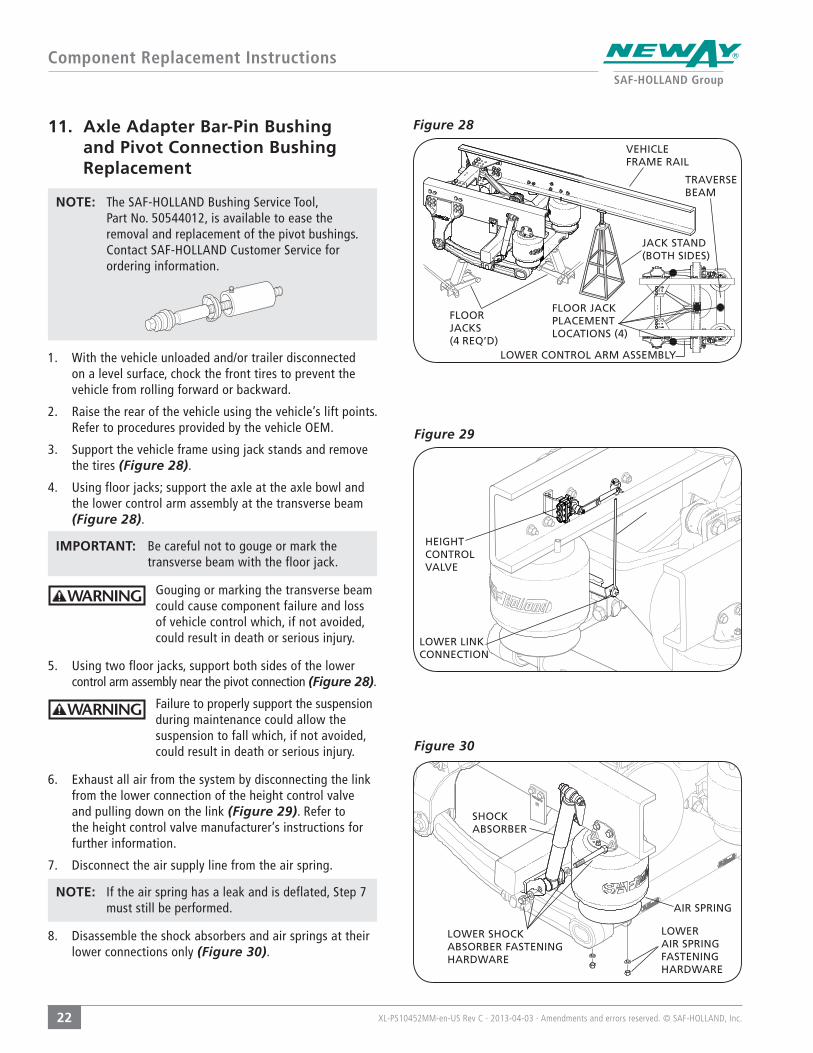
Figure 2811. Axle Adapter Bar-Pin Bushing and Pivot Connection Bushing Replacement
NOTE: The SAF-HOLLAND Bushing Service Tool, Part No. 50544012, is available to ease the removal and replacement of the pivot bushings. Contact SAF-HOLLAND Customer Service for ordering information.
1. With the vehicle unloaded and/or trailer disconnected on a level surface, chock the front tires to prevent the vehicle from rolling forward or backward.
2. Raise the rear of the vehicle using the vehicle’s lift points. Refer to procedures provided by the vehicle OEM.
3. Support the vehicle frame using jack stands and remove the tires (Figure 28).
4. Using floor jacks; support the axle at the axle bowl and the lower control arm assembly at the transverse beam (Figure 28).
IMPORTANT: Be careful not to gouge or mark the transverse beam with the floor jack.
Gouging or marking the transverse beam could cause component failure and loss of vehicle control which, if not avoided, could result in death or serious injury.
5. Using two floor jacks, support both sides of the lower control arm assembly near the pivot connection (Figure 28).
Failure to properly support the suspension during maintenance could allow the suspension to fall which, if not avoided, could result in death or serious injury.
6. Exhaust all air from the system by disconnecting the link from the lower connection of the height control valve and pulling down on the link (Figure 29). Refer to the height control valve manufacturer’s instructions for further information.
7. Disconnect the air supply line from the air spring.
NOTE: If the air spring has a leak and is deflated, Step 7 must still be performed.
8. Disassemble the shock absorbers and air springs at their lower connections only (Figure 30).
VEHICLE FRAME RAIL
JACK STAND(BOTH SIDES)
TRAVERSEBEAM
FLOOR JACKS(4 REQ’D)
FLOOR JACK PLACEMENT LOCATIONS (4)
LOWER CONTROL ARM ASSEMBLY
Figure 29
HEIGHT CONTROL VALVE
LOWER LINK CONNECTION
Figure 30
SHOCK ABSORBER
LOWER SHOCK ABSORBER FASTENING HARDWARE
AIR SPRING
LOWER AIR SPRING FASTENING HARDWARE
XL-PS10452MM-en-US Rev C · 2013-04-03 · Amendments and errors reserved. © SAF-HOLLAND, Inc.
Component Replacement Instructions
23
Figure 32
Figure 33
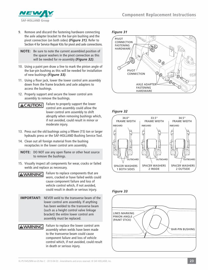
Figure 31 9. Remove and discard the fastening hardware connecting the axle adapter bracket to the bar-pin bushing and the pivot connection (on both sides) (Figure 31). Refer to Section 4 for Service Repair Kits for pivot and axle connections.
NOTE: Be sure to note the current assembled position of the spacer washers in the pivot connection as this will be needed for re-assembly (Figure 32).
10. Using a paint pen draw a line to mark the pinion angle of the bar-pin bushing as this will be needed for installation of new bushings (Figure 33).
11. Using a floor jack, lower the lower control arm assembly down from the frame brackets and axle adapters to access the bushings.
12. Properly support and secure the lower control arm assembly to remove the bushings.
Failure to properly support the lower control arm assembly could allow the lower control arm assembly to shift abruptly when removing bushings which, if not avoided, could result in minor or moderate injury.
13. Press out the old bushings using a fifteen (15) ton or larger hydraulic press or the SAF-HOLLAND Bushing Service Tool.
14. Clean out all foreign material from the bushing receptacles in the lower control arm assembly.
NOTE: DO NOT use any open flame or other heat source to remove the bushings.
15. Visually inspect all components for wear, cracks or failed welds and replace as necessary.
Failure to replace components that are worn, cracked or have failed welds could cause component failure and loss of vehicle control which, if not avoided, could result in death or serious injury.
IMPORTANT: NEVER weld to the transverse beam of the lower control arm assembly. If anything has been welded to the transverse beam (such as a height control valve linkage bracket) the entire lower control arm assembly must be replaced.
Failure to replace the lower control arm assembly when welds have been made to the transverse beam could cause component failure and loss of vehicle control which, if not avoided, could result in death or serious injury.
AXLE ADAPTER FASTENING HARDWARE
PIVOT CONNECTION
PIVOT CONNECTION FASTENING HARDWARE
SPACER WASHERS1 BOTH SIDES
34.0" FRAME WIDTH
34.5" FRAME WIDTH
33.5" FRAME WIDTH
SPACER WASHERS2 OUTSIDE
SPACER WASHERS2 INSIDE
LINES MARKING PINION ANGLE(PAINT STICK)
BAR-PIN BUSHING
INBOARD INBOARD INBOARD
OUTBOARD OUTBOARD OUTBOARD
XL-PS10452MM-en-US Rev C · 2013-04-03 · Amendments and errors reserved. © SAF-HOLLAND, Inc.
Component Replacement Instructions
24
Figure 35
Figure 36
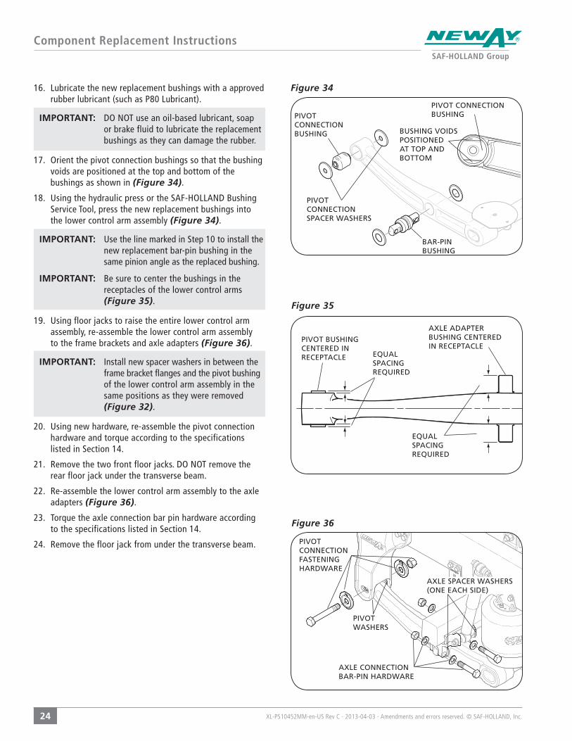
Figure 3416. Lubricate the new replacement bushings with a approved rubber lubricant (such as P80 Lubricant).
IMPORTANT: DO NOT use an oil-based lubricant, soap or brake fluid to lubricate the replacement bushings as they can damage the rubber.
17. Orient the pivot connection bushings so that the bushing voids are positioned at the top and bottom of the bushings as shown in (Figure 34).
18. Using the hydraulic press or the SAF-HOLLAND Bushing Service Tool, press the new replacement bushings into the lower control arm assembly (Figure 34).
IMPORTANT: Use the line marked in Step 10 to install the new replacement bar-pin bushing in the same pinion angle as the replaced bushing.
IMPORTANT: Be sure to center the bushings in the receptacles of the lower control arms (Figure 35).
19. Using floor jacks to raise the entire lower control arm assembly, re-assemble the lower control arm assembly to the frame brackets and axle adapters (Figure 36).
IMPORTANT: Install new spacer washers in between the frame bracket flanges and the pivot bushing of the lower control arm assembly in the same positions as they were removed (Figure 32).
20. Using new hardware, re-assemble the pivot connection hardware and torque according to the specifications listed in Section 14.
21. Remove the two front floor jacks. DO NOT remove the rear floor jack under the transverse beam.
22. Re-assemble the lower control arm assembly to the axle adapters (Figure 36).
23. Torque the axle connection bar pin hardware according to the specifications listed in Section 14.
24. Remove the floor jack from under the transverse beam.
PIVOT CONNECTION BUSHING
PIVOT CONNECTION BUSHING
BAR-PIN BUSHING
BUSHING VOIDS POSITIONED AT TOP AND BOTTOM
PIVOT CONNECTION SPACER WASHERS
EQUAL SPACING REQUIRED
PIVOT BUSHING CENTERED IN RECEPTACLE
AXLE ADAPTER BUSHING CENTERED IN RECEPTACLE
EQUAL SPACING REQUIRED
AXLE CONNECTION BAR-PIN HARDWARE
PIVOT CONNECTION FASTENING HARDWARE
PIVOT WASHERS
AXLE SPACER WASHERS (ONE EACH SIDE)

XL-PS10452MM-en-US Rev C · 2013-04-03 · Amendments and errors reserved. © SAF-HOLLAND, Inc.
Component Replacement Instructions
25
25. Re-connect the air springs, shock absorbers (Figure 37)and height control valve lower link and torque hardware according to the specifications listed in Section 14.
26. Re-install the tires and any remaining components and torque the tire hardware according to the wheel manufacturer’s and/or OEM’s specifications.
27. Remove the floor jack supporting the axle bowl.
28. Raise the rear of the vehicle using the vehicle’s lift points to remove the jack stands under the vehicle frame. Refer to procedures provided by the vehicle OEM.
29. Increase suspension air system reservoir pressure in excess of 70 psig (4.83 bars) and check for leaks. All air springs should inflate and raise the suspension to the proper ride height.
30. Check the ride height and make sure it is within ± .25" (6 mm) of design specification and adjust as necessary. Refer to the ride height adjustment instructions shown in Section 6.
31. Check the alignment of the suspension per vehicle OEM instructions. If re-alignment is necessary, refer to the alignment procedures described in Section 7.
Figure 37
SHOCK ABSORBER
LOWER SHOCK ABSORBER FASTENING HARDWARE
AIR SPRING
LOWER AIR SPRING FASTENING HARDWARE

XL-PS10452MM-en-US Rev C · 2013-04-03 · Amendments and errors reserved. © SAF-HOLLAND, Inc.
Component Replacement Instructions
26
Figure 40
Figure 38 12. V-Rod Bushing Replacement
1. With the vehicle unloaded and/or trailer disconnected on a level surface, chock the front tires to prevent the vehicle from rolling forward or backward.
2. Raise the rear of the vehicle using the vehicle’s lift points. Refer to procedures provided by the vehicle OEM.
3. Support the vehicle frame using jack stands (Figure 38).
Failure to properly support the vehicle prior to commencing work could create a crush hazard which, if not avoided, could result in death or serious injury.
4. Using a floor jack support the axle at the axle bowl and block the axle to prevent it from rotating when the V-Rod is removed from the upper axle adapter.
5. Exhaust all air from the system by disconnecting the link from the lower connection of the height control valve and pulling down on the link (Figure 39). Refer to the height control valve manufacturer’s instructions for further information.
6. Disconnect the air supply line from the air spring.
NOTE: If the air spring has a leak and is deflated, Step 7 must still be performed.
7. Using the floor jack, lower the suspension until the shock absorbers are fully extended.
8. Remove and discard the fastening hardware connecting the V-Rod to the frame crossmember (Figure 40). Refer to Section 4 for SRK-645 for replacement kit.
9. Mark position of V-Rod upper axle bracket pinion plate on the bracket with a paint pen so the plate can be re-installed in the same position. Refer to Section 8A for additional information.
10. Remove the rear V-Rod attachment bolt from the upper axle bracket (Figure 39).
IMPORTANT: Be sure the two spacer washers located between the inside faces of the upper axle bracket and side of the V-Rod do not fall out.
NOTE: There are backer plates and spacers in between the V-Rod bushing and the frame crossmember. Remove the backer plates and spacers and set aside for re-assembly.
V-ROD FASTENING HARDWARE
V-ROD FASTENING HARDWARE
V-ROD
REAR V-ROD ATTACHMENT BOLT
BACKER PLATE OR OEM SUPPLIED SPACER
Figure 39
HEIGHT CONTROL VALVE
LOWER LINK CONNECTION
FLOOR JACK PLACEMENT UNDER AXLE BOWL
VEHICLE FRAME RAIL
JACK STAND(BOTH SIDES)
UPPER AXLE BRACKET
FRAME CROSSMEMBER
XL-PS10452MM-en-US Rev C · 2013-04-03 · Amendments and errors reserved. © SAF-HOLLAND, Inc.
Component Replacement Instructions
27
Figure 42
Figure 43
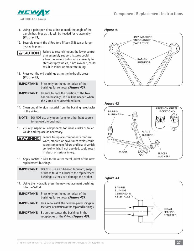
Figure 41 11. Using a paint pen draw a line to mark the angle of the bar-pin bushings as this will be needed for re-assembly (Figure 41).
12. Securely mount the V-Rod to a fifteen (15) ton or larger hydraulic press.
Failure to securely mount the lower control arm assembly support fixtures could allow the lower control arm assembly to shift abruptly which, if not avoided, could result in minor or moderate injury.
13. Press out the old bushings using the hydraulic press (Figure 42).
IMPORTANT: Press only on the outer jacket of the bushings for removal (Figure 42).
IMPORTANT: Be sure to note the position of the two bar-pin bushings. This will be needed when the V-Rod is re-assembled later.
14. Clean out all foreign material from the bushing receptacles in the V-Rod.
NOTE: DO NOT use any open flame or other heat source to remove the bushings.
15. Visually inspect all components for wear, cracks or failed welds and replace as necessary.
Failure to replace components that are worn, cracked or have failed welds could cause component failure and loss of vehicle control which, if not avoided, could result in death or serious injury.
16. Apply Loctite™ 603 to the outer metal jacket of the new replacement bushings.
IMPORTANT: DO NOT use an oil-based lubricant, soap or brake fluid to lubricate the replacement bushings as they can damage the rubber.
17. Using the hydraulic press the new replacement bushings into the V-Rod.
IMPORTANT: Press only on the outer jacket of the bushings for removal (Figure 42).
IMPORTANT: Be sure to install the new bar-pin bushings in the same orientation as the replaced bushings.
IMPORTANT: Be sure to center the bushings in the receptacles of the V-Rod (Figure 43).
BAR-PIN BUSHINGS
V-ROD BUSHING
PRESS ON OUTER JACKET ONLY
SPACER WASHERS
V-ROD
EQUAL SPACING REQUIRED
BAR-PIN BUSHING CENTERED IN RECEPTACLE
BAR-PIN BUSHINGS
LINES MARKING PINION ANGLE(PAINT STICK)
XL-PS10452MM-en-US Rev C · 2013-04-03 · Amendments and errors reserved. © SAF-HOLLAND, Inc.
Component Replacement Instructions
28
Figure 45
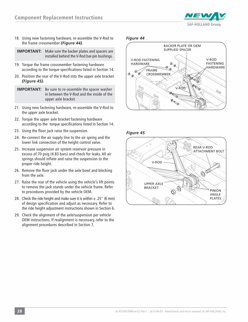
Figure 4418. Using new fastening hardware, re-assemble the V-Rod to the frame crossmember (Figure 44).
IMPORTANT: Make sure the backer plates and spacers are installed behind the V-Rod bar-pin bushings.
19. Torque the frame crossmember fastening hardware according to the torque specifications listed in Section 14.
20. Position the rear of the V-Rod into the upper axle bracket (Figure 45).
IMPORTANT: Be sure to re-assemble the spacer washer in between the V-Rod and the inside of the upper axle bracket.
21. Using new fastening hardware, re-assemble the V-Rod to the upper axle bracket.
22. Torque the upper axle bracket fastening hardware according to the torque specifications listed in Section 14.
23. Using the floor jack raise the suspension.
24. Re-connect the air supply line to the air spring and the lower link connection of the height control valve.
25. Increase suspension air system reservoir pressure in excess of 70 psig (4.83 bars) and check for leaks. All air springs should inflate and raise the suspension to the proper ride height.
26. Remove the floor jack under the axle bowl and blocking from the axle.
27. Raise the rear of the vehicle using the vehicle’s lift points to remove the jack stands under the vehicle frame. Refer to procedures provided by the vehicle OEM.
28. Check the ride height and make sure it is within ± .25" (6 mm) of design specification and adjust as necessary. Refer to the ride height adjustment instructions shown in Section 6.
29. Check the alignment of the axle/suspension per vehicle OEM instructions. If realignment is necessary, refer to the alignment procedures described in Section 7.
V-ROD FASTENING HARDWARE
V-ROD FASTENING HARDWARE
V-ROD
REAR V-ROD ATTACHMENT BOLT
PINION ANGLE PLATES
UPPER AXLE BRACKET
V-ROD
FRAME CROSSMEMBER
BACKER PLATE OR OEM SUPPLIED SPACER

XL-PS10452MM-en-US Rev C · 2013-04-03 · Amendments and errors reserved. © SAF-HOLLAND, Inc.
Component Replacement Instructions
29
Figure 47
Figure 48
Figure 46 13. Frame Bracket Replacement
IMPORTANT: The Neway ADZ Series Suspension frame brackets are symmetrical and can be installed on either side of the vehicle. Typically an adjustable frame bracket is located on the road side of the vehicle and a non-adjustable frame bracket on the curb side of the vehicle. Be sure one non-adjustable and one adjustable frame bracket is used for each suspension.
1. With the vehicle unloaded and/or trailer disconnected on a level surface, chock the front tires to prevent the vehicle from rolling forward or backward.
2. Raise the rear of the vehicle using the vehicle’s lift points. Refer to procedures provided by the vehicle OEM.
3. Support the vehicle frame using jack stands and remove the tires (Figure 46).
Failure to properly support the vehicle prior to commencing work could create a crush hazard which, if not avoided, could result in death or serious injury.
4. Using floor jacks; support the axle at the axle bowl and the lower control arm assembly at the transverse beam (Figure 46).
IMPORTANT: Be careful not to gouge or mark the transverse beam with the floor jack.
Failure to avoid gouging or marking the transverse beam could cause component failure and loss of vehicle control which, if not avoided, could result in death or serious injury.
5. Using two floor jacks, support both sides of the lower control arm assembly near the pivot connection (Figure 46).
Failure to properly support the suspension during maintenance could allow the suspension to fall which, if not avoided, could result in death or serious injury.
6. Exhaust all air from the system by disconnecting the link from the lower connection of the height control valve and pulling down on the link (Figure 47). Refer to the height control valve manufacturer’s instructions for further information.
7. Disconnect the air supply line from the air spring.
NOTE: If the air spring has a leak and is deflated, Step 7 must still be performed.
8. Remove and discard the pivot connection bolt and fastening hardware at the pivot connection (both sides) (Figure 48). Refer to SRK-643 and -644 in Section 4 for replacement hardware.
IMPORTANT: Be sure to note the positions of the spacer washers between the frame bracket flanges and the pivot end of the lower control arm assembly (Figure 32 and 48).
PIVOT CONNECTION
PIVOT CONNECTIONBOLT
ALIGNMENT COLLAR
PIVOT CONNECTION FASTENING HARDWARE
VEHICLE FRAME RAIL
JACK STAND(BOTH SIDES)
FLOOR JACKS(4 REQ’D)
FLOOR JACK PLACEMENT LOCATIONS (4)
HEIGHT CONTROL VALVE
LOWER LINK CONNECTION
PIVOT WASHERS
SPACER WASHERS INSIDE FRAME BRACKET (NOT SHOWN)
TRAVERSEBEAM
LOWER CONTROL ARM ASSEMBLY
XL-PS10452MM-en-US Rev C · 2013-04-03 · Amendments and errors reserved. © SAF-HOLLAND, Inc.
Component Replacement Instructions
30
Figure 48
Figure 49
Figure 47
FRAME BRACKET
FRAME BRACKET
LOWER CONTROL ARM ASSEMBLY
FRAME RAIL
FRAME BRACKET FASTENING HARDWARE
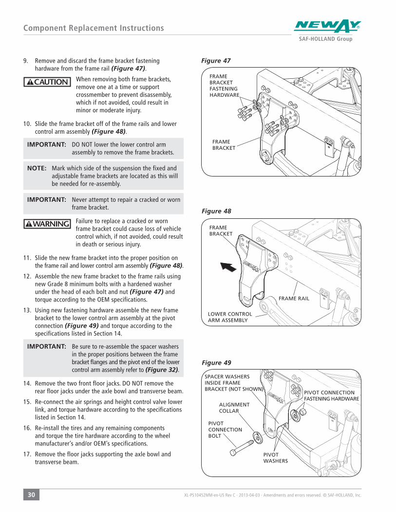
9. Remove and discard the frame bracket fastening hardware from the frame rail (Figure 47).
When removing both frame brackets, remove one at a time or support crossmember to prevent disassembly, which if not avoided, could result in minor or moderate injury.
10. Slide the frame bracket off of the frame rails and lower control arm assembly (Figure 48).
IMPORTANT: DO NOT lower the lower control arm assembly to remove the frame brackets.
NOTE: Mark which side of the suspension the fixed and adjustable frame brackets are located as this will be needed for re-assembly.
IMPORTANT: Never attempt to repair a cracked or worn frame bracket.
Failure to replace a cracked or worn frame bracket could cause loss of vehicle control which, if not avoided, could result in death or serious injury.
11. Slide the new frame bracket into the proper position on the frame rail and lower control arm assembly (Figure 48).
12. Assemble the new frame bracket to the frame rails using new Grade 8 minimum bolts with a hardened washer under the head of each bolt and nut (Figure 47) and torque according to the OEM specifications.
13. Using new fastening hardware assemble the new frame bracket to the lower control arm assembly at the pivot connection (Figure 49) and torque according to the specifications listed in Section 14.
IMPORTANT: Be sure to re-assemble the spacer washers in the proper positions between the frame bracket flanges and the pivot end of the lower control arm assembly refer to (Figure 32).
14. Remove the two front floor jacks. DO NOT remove the rear floor jacks under the axle bowl and transverse beam.
15. Re-connect the air springs and height control valve lower link, and torque hardware according to the specifications listed in Section 14.
16. Re-install the tires and any remaining components and torque the tire hardware according to the wheel manufacturer’s and/or OEM’s specifications.
17. Remove the floor jacks supporting the axle bowl and transverse beam.
SPACER WASHERS INSIDE FRAME BRACKET (NOT SHOWN)
PIVOT CONNECTIONBOLT
ALIGNMENT COLLAR
PIVOT CONNECTION FASTENING HARDWARE
PIVOT WASHERS

XL-PS10452MM-en-US Rev C · 2013-04-03 · Amendments and errors reserved. © SAF-HOLLAND, Inc.
Component Replacement Instructions
31
18. Raise the rear of the vehicle using the vehicle’s lift points to remove the jack stands under the vehicle frame. Refer to procedures provided by the vehicle OEM.
19. Increase suspension air system reservoir pressure in excess of 70 psig (4.83 bars) and check for leaks. All air springs should inflate and raise the suspension to the proper ride height.
20. Check the ride height and make sure it is within ± .25" (6 mm) of design specification and adjust as necessary. Refer to the ride height adjustment instructions shown in Section 6.
21. Re-align the ADZ suspension according to the axle alignment procedures shown in Section 7.
XL-PS10452MM-en-US Rev C · 2013-04-03 · Amendments and errors reserved. © SAF-HOLLAND, Inc.
Torque Specifications
32
COMPONENTFASTENER
SIZE
NOMINAL TORQUE VALUE
TORQUE RANGE
ADZ Pivot Connection
1 - 1/8"-7(28.6 mm )
634 ft.-lbs. (860 N•m)
571-697 ft.-lbs.(773-945 N•m)
Upper and Lower Shock Mount
3/4"-10(19.1 mm)
158 ft.-lbs. (214 N•m)
142-174 ft.-lbs.(193-235 N•m)
Upper and Lower Air Spring
1/2"-13(12.7 mm)
37 ft.-lbs. (50 N•m)
33-41 ft.-lbs.(45-55 N•m)
Upper Air Spring3/4"-16
(19.1 mm)37 ft.-lbs. (50 N•m)
33-41 ft.-lbs.(45-55 N•m)
V-Rod Connection at Axle
1"-8(25.4 mm)
634 ft.-lbs. (860 N•m)
571-697 ft.-lbs.(773-945 N•m)
Axle Adapter Connection – Bar-pin
1"-8(25.4 mm)
634 ft.-lbs. (860 N•m)
571-697 ft.-lbs.(773-945 N•m)
Crossmember Wing Plates to Crossmember Center Channel
3/4"-10(19.1 mm)
300 ft.-lbs.(407 N•m)
260-340 ft.-lbs.(352-461 N•m)
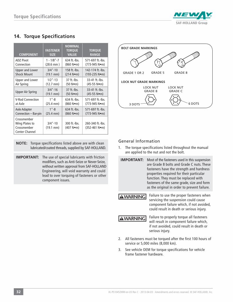
14. Torque Specifications
NOTE: Torque specifications listed above are with clean lubricated/coated threads, supplied by SAF-HOLLAND.
IMPORTANT: The use of special lubricants with friction modifiers, such as Anti-Seize or Never-Seize, without written approval from SAF-HOLLAND Engineering, will void warranty and could lead to over torquing of fasteners or other component issues.
General Information
1. The torque specifications listed throughout the manual are applied to the nut and not the bolt.
IMPORTANT: Most of the fasteners used in this suspension are Grade 8 bolts and Grade C nuts. These fasteners have the strength and hardness properties required for their particular function. They must be replaced with fasteners of the same grade, size and form as the original in order to prevent failure.
Failure to use the proper fasteners when servicing the suspension could cause component failure which, if not avoided, could result in death or serious injury.
Failure to properly torque all fasteners will result in component failure which, if not avoided, could result in death or serious injury.
2. All fasteners must be torqued after the first 100 hours of service or 5,000 miles (8,000 km).
3. See vehicle OEM for torque specifications for vehicle frame fastener hardware.
GRADE 1 OR 2
BOLT GRADE MARKINGS
LOCK NUT GRADE MARKINGS
3 DOTS
LOCK NUT GRADE B
LOCK NUT GRADE C
6 DOTS
GRADE 5 GRADE 8
XL-PS10452MM-en-US Rev C · 2013-04-03 · Amendments and errors reserved. © SAF-HOLLAND, Inc.
Maintenance and Service Schedule
33
15. Routine Maintenance and Daily Inspection
15.A Daily Inspection
1. Daily or before each trip, check the suspension to be sure it is fully operational and visually free of any obvious signs of failure in any major component.
2. Visually inspect air springs for sufficient and equal pressure and that the suspension is set at the proper ride height. See ride height measurement and re-setting instructions as described in Section 6. Service as necessary.
15.B Initial 5,000 Miles (8,000 km) or 100 Hours of Service
1. Suspension ride height (underside of frame to centerline of axle) MUST BE WITHIN ±.25" OF RECOMMENDED DESIGN HEIGHT. See ride height measurement and re-setting instructions as described in Section 6. Service as necessary.
An improperly set ride height could result in suspension component damage and/or poor vehicle ride performance.
2. After initial 5,000 miles (8,000 km) or 100 hours of service, inspect bolts and nuts at the pivot connections, frame crossmember connections, V-Rod connections and axle connections to ensure they are properly torqued. Check all other nuts and bolts for proper torque. Re-torque as necessary according to the specifications listed in Section 14.
IMPORTANT: It is recommended to monitor torque of any joint that required re-torque at the 5,000 mile/100 hours of service interval. Continue to monitor these joints daily until no change occurs at any joint that required re-torquing. Establish a re-check interval equivalent to findings of this monitoring.
Failure to maintain proper joint torque could lead to joint failure which, if not avoided, could result in death or serious injury.
3. With vehicle on level surface and air pressure in excess of 70 psig, verify that all air springs are of sufficient and equal firmness.
4. Visually check all air control system fittings for air leaks by applying a soapy water solution and checking for bubbles at all air connections and fittings.
15.C Routine Maintenance - 50,000 Miles (80,000 km) / 1,000 Hours of Service, or as Needed
Inspect suspension components per 5,000 mile (8,000 km)inspection. Check all other suspension components for any sign of damage, looseness, torque loss, wear or cracks. To prevent equipment breakdown; repair, tighten or replace damaged or loosened components.
15.D Visual Inspection Procedure
IMPORTANT: A schedule for physical and visual inspections should be established by the operator based on severity of operation or damage to the vehicle could occur.
IMPORTANT: During each pre-trip and safety inspection of the vehicle, a visual inspection of the suspension should be done or damage to the vehicle could occur.
Failure to correct out of specification conditions during routine inspections could result in poor suspension performance which, if not avoided, could result in damage to trailer components.
Visually check for:
• Bolt Movement – loose dirt, rust or metal wear around bolt head and nut
• Air Springs – clearances, wear damage, and proper inflation
• Shock Absorbers – leaking or damaged
• Cracked Parts or Welds
XL-PS10452MM-en-US Rev C · 2013-04-03 · Amendments and errors reserved. © SAF-HOLLAND, Inc.
Troubleshooting
34
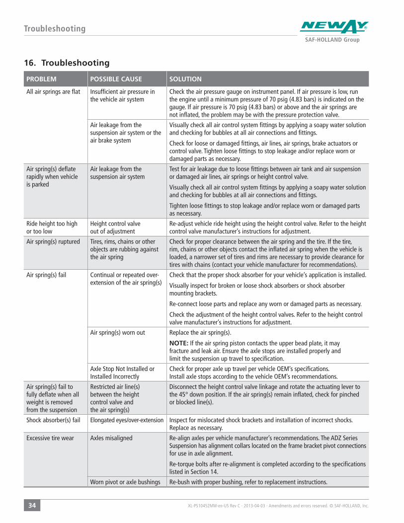
PROBLEM POSSIBLE CAUSE SOLUTION
All air springs are flat Insufficient air pressure in the vehicle air system
Check the air pressure gauge on instrument panel. If air pressure is low, run the engine until a minimum pressure of 70 psig (4.83 bars) is indicated on the gauge. If air pressure is 70 psig (4.83 bars) or above and the air springs are not inflated, the problem may be with the pressure protection valve.
Air leakage from the suspension air system or the air brake system
Visually check all air control system fittings by applying a soapy water solution and checking for bubbles at all air connections and fittings.
Check for loose or damaged fittings, air lines, air springs, brake actuators or control valve. Tighten loose fittings to stop leakage and/or replace worn or damaged parts as necessary.
Air spring(s) deflate rapidly when vehicle is parked
Air leakage from the suspension air system
Test for air leakage due to loose fittings between air tank and air suspension or damaged air lines, air springs or height control valve.
Visually check all air control system fittings by applying a soapy water solution and checking for bubbles at all air connections and fittings.
Tighten loose fittings to stop leakage and/or replace worn or damaged parts as necessary.
Ride height too high or too low
Height control valve out of adjustment
Re-adjust vehicle ride height using the height control valve. Refer to the height control valve manufacturer’s instructions for adjustment.
Air spring(s) ruptured Tires, rims, chains or other objects are rubbing against the air spring
Check for proper clearance between the air spring and the tire. If the tire, rim, chains or other objects contact the inflated air spring when the vehicle is loaded, a narrower set of tires and rims are necessary to provide clearance for tires with chains (contact your vehicle manufacturer for recommendations).
Air spring(s) fail Continual or repeated over-extension of the air spring(s)
Check that the proper shock absorber for your vehicle’s application is installed.
Visually inspect for broken or loose shock absorbers or shock absorber mounting brackets.
Re-connect loose parts and replace any worn or damaged parts as necessary.
Check the adjustment of the height control valves. Refer to the height control valve manufacturer’s instructions for adjustment.
Air spring(s) worn out Replace the air spring(s).
NOTE: If the air spring piston contacts the upper bead plate, it may fracture and leak air. Ensure the axle stops are installed properly and limit the suspension up travel to specification.
Axle Stop Not Installed or Installed Incorrectly
Check for proper axle up travel per vehicle OEM’s specifications.Install axle stops according to the vehicle OEM’s recommendations.
Air spring(s) fail to fully deflate when all weight is removed from the suspension
Restricted air line(s) between the height control valve and the air spring(s)
Disconnect the height control valve linkage and rotate the actuating lever to the 45° down position. If the air spring(s) remain inflated, check for pinched or blocked line(s).
Shock absorber(s) fail Elongated eyes/over-extension Inspect for mislocated shock brackets and installation of incorrect shocks. Replace as necessary.
Excessive tire wear Axles misaligned Re-align axles per vehicle manufacturer’s recommendations. The ADZ Series Suspension has alignment collars located on the frame bracket pivot connections for use in axle alignment.
Re-torque bolts after re-alignment is completed according to the specifications listed in Section 14.
Worn pivot or axle bushings Re-bush with proper bushing, refer to replacement instructions.
16. Troubleshooting
XL-PS10452MM-en-US Rev C · 2013-04-03 · Amendments and errors reserved. © SAF-HOLLAND, Inc.
Troubleshooting
35
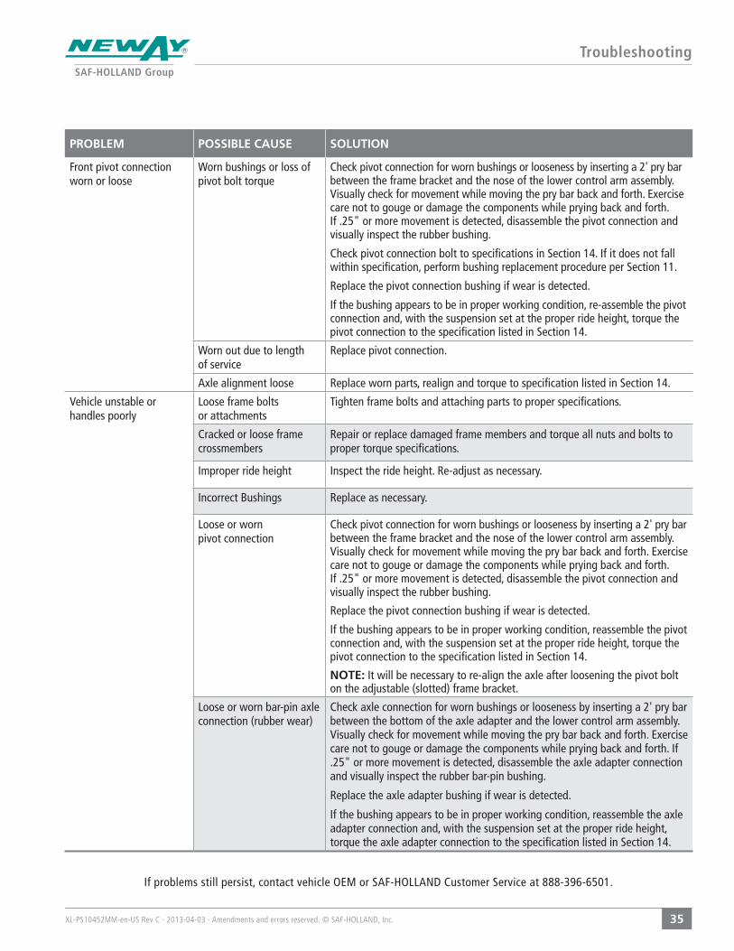
If problems still persist, contact vehicle OEM or SAF-HOLLAND Customer Service at 888-396-6501.
PROBLEM POSSIBLE CAUSE SOLUTION
Front pivot connection worn or loose
Worn bushings or loss of pivot bolt torque
Check pivot connection for worn bushings or looseness by inserting a 2' pry bar between the frame bracket and the nose of the lower control arm assembly. Visually check for movement while moving the pry bar back and forth. Exercise care not to gouge or damage the components while prying back and forth. If .25" or more movement is detected, disassemble the pivot connection and visually inspect the rubber bushing.
Check pivot connection bolt to specifications in Section 14. If it does not fall within specification, perform bushing replacement procedure per Section 11.
Replace the pivot connection bushing if wear is detected.
If the bushing appears to be in proper working condition, re-assemble the pivot connection and, with the suspension set at the proper ride height, torque the pivot connection to the specification listed in Section 14.
Worn out due to length of service
Replace pivot connection.
Axle alignment loose Replace worn parts, realign and torque to specification listed in Section 14.
Vehicle unstable or handles poorly
Loose frame bolts or attachments
Tighten frame bolts and attaching parts to proper specifications.
Cracked or loose frame crossmembers
Repair or replace damaged frame members and torque all nuts and bolts to proper torque specifications.
Improper ride height Inspect the ride height. Re-adjust as necessary.
Incorrect Bushings Replace as necessary.
Loose or worn pivot connection
Check pivot connection for worn bushings or looseness by inserting a 2' pry bar between the frame bracket and the nose of the lower control arm assembly. Visually check for movement while moving the pry bar back and forth. Exercise care not to gouge or damage the components while prying back and forth. If .25" or more movement is detected, disassemble the pivot connection and visually inspect the rubber bushing.
Replace the pivot connection bushing if wear is detected.
If the bushing appears to be in proper working condition, reassemble the pivot connection and, with the suspension set at the proper ride height, torque the pivot connection to the specification listed in Section 14.
NOTE: It will be necessary to re-align the axle after loosening the pivot bolt on the adjustable (slotted) frame bracket.
Loose or worn bar-pin axle connection (rubber wear)
Check axle connection for worn bushings or looseness by inserting a 2' pry bar between the bottom of the axle adapter and the lower control arm assembly. Visually check for movement while moving the pry bar back and forth. Exercise care not to gouge or damage the components while prying back and forth. If .25" or more movement is detected, disassemble the axle adapter connection and visually inspect the rubber bar-pin bushing.
Replace the axle adapter bushing if wear is detected.
If the bushing appears to be in proper working condition, reassemble the axle adapter connection and, with the suspension set at the proper ride height, torque the axle adapter connection to the specification listed in Section 14.
SAF-HOLLAND USA · 888.396.6501 · Fax 800.356.3929
www.safholland.us
SAF-HOLLAND CANADA · 519.537.3494 · Fax 800.565.7753
WESTERN CANADA · 604.574.7491 · Fax 604.574.0244
www.safholland.ca
SAF-HOLLAND MEXICO · 52.55.5362.8743 · Fax 52.55.5362.8743
www.safholland.com.mx
XL-P
S104
52M
M-e
n-U
S Re
v C
· 201
3-04
-03
· Am
endm
ents
and
err
ors
rese
rved
. ©
SAF
-HO
LLAN
D, In
c.
From fifth wheel rebuild kits to suspension bushing repair kits,
SAF-HOLLAND Original Parts are the same quality components used
in the original component assembly.
SAF-HOLLAND Original Parts are tested and designed to provide
maximum performance and durability. Will-fits, look-a likes or, worse
yet, counterfeit parts will only limit the performance potential and
could possibly void SAF-HOLLAND’s warranty. Always be sure to spec
SAF-HOLLAND Original Parts when servicing your
SAF-HOLLAND product.
SAF-HOLLAND USA, INC.1950 Industrial Blvd, Muskegon, MI 49442www.safholland.com