Embed Size (px)
Citation preview
Maintenance and Service GuideHP Pavilion dv9000 and dv9200 Notebook PC
Document Part Number: 417615-004
December 2007
This guide is a troubleshooting reference used for maintaining and servicing the computer. It provides comprehensive information on identifying computer features, components, and spare parts; troubleshooting computer problems; and performing computer disassembly procedures.

© Copyright 2006, 2007 Hewlett-Packard Development Company, L.P.
Microsoft, Windows, and Windows Vista are either trademarks or registered trademarks of Microsoft Corporation in the United States and/or other countries. Intel and Core are trademarks or registered trademarks of Intel Corporation or its subsidiaries in the United States and other countries. Bluetooth is a trademark owned by its proprietor and used by Hewlett-Packard Company under license. SD Logo is a trademark of its proprietor. AMD, the AMD Arrow logo and combinations thereof are trademarks of Advanced Micro Devices, Inc.
The information contained herein is subject to change without notice. The only warranties for HP products and services are set forth in the express warranty statements accompanying such products and services. Nothing herein should be construed as constituting an additional warranty. HP shall not be liable for technical or editorial errors or omissions contained herein.
Maintenance and Service GuideHP Pavilion dv9000 and dv9200 Notebook PCFourth Edition: December 2007First Edition: August 2006Document Part Number: 417615-004

Safety warning notice
ÅWARNING: To reduce the possibility of heat-related injuries or of overheating the computer, do not place the computer directly on your lap or obstruct the computer air vents. Use the computer only on a hard, flat surface. Do not allow another hard surface, such as an adjoining optional printer, or a soft surface, such as pillows or rugs or clothing, to block airflow. Also, do not allow the AC adapter to contact the skin or a soft surface, such as pillows or rugs or clothing, during operation. The computer and the AC adapter comply with the user-accessible surface temperature limits defined by the International Standard for Safety of Information Technology Equipment (IEC 60950).

Contents
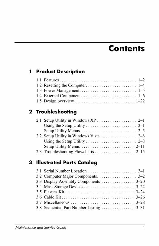
1 Product Description
1.1 Features . . . . . . . . . . . . . . . . . . . . . . . . . . . . . . . . . . . 1–21.2 Resetting the Computer. . . . . . . . . . . . . . . . . . . . . . . 1–41.3 Power Management. . . . . . . . . . . . . . . . . . . . . . . . . . 1–51.4 External Components . . . . . . . . . . . . . . . . . . . . . . . . 1–61.5 Design overview . . . . . . . . . . . . . . . . . . . . . . . . . . . 1–22
2 Troubleshooting
2.1 Setup Utility in Windows XP . . . . . . . . . . . . . . . . . . 2–1Using the Setup Utility . . . . . . . . . . . . . . . . . . . . . . . 2–1Setup Utility Menus . . . . . . . . . . . . . . . . . . . . . . . . . 2–5
2.2 Setup Utility in Windows Vista . . . . . . . . . . . . . . . . 2–8Using the Setup Utility . . . . . . . . . . . . . . . . . . . . . . . 2–8Setup Utility Menus . . . . . . . . . . . . . . . . . . . . . . . . 2–11
2.3 Troubleshooting Flowcharts . . . . . . . . . . . . . . . . . . 2–15
3 Illustrated Parts Catalog
3.1 Serial Number Location . . . . . . . . . . . . . . . . . . . . . . 3–13.2 Computer Major Components. . . . . . . . . . . . . . . . . . 3–23.3 Display Assembly Components . . . . . . . . . . . . . . . 3–203.4 Mass Storage Devices . . . . . . . . . . . . . . . . . . . . . . . 3–223.5 Plastics Kit . . . . . . . . . . . . . . . . . . . . . . . . . . . . . . . 3–243.6 Cable Kit . . . . . . . . . . . . . . . . . . . . . . . . . . . . . . . . . 3–263.7 Miscellaneous . . . . . . . . . . . . . . . . . . . . . . . . . . . . . 3–283.8 Sequential Part Number Listing . . . . . . . . . . . . . . . 3–31
Maintenance and Service Guide i

Contents
4 Removal and Replacement Preliminaries
4.1 Tools Required . . . . . . . . . . . . . . . . . . . . . . . . . . . . . 4–14.2 Service Considerations . . . . . . . . . . . . . . . . . . . . . . . 4–2
Plastic Parts . . . . . . . . . . . . . . . . . . . . . . . . . . . . . . . . 4–2Cables and Connectors . . . . . . . . . . . . . . . . . . . . . . . 4–2
4.3 Preventing Damage to Removable Drives . . . . . . . . 4–34.4 Preventing Electrostatic Damage . . . . . . . . . . . . . . . 4–44.5 Packaging and Transporting Precautions . . . . . . . . . 4–54.6 Workstation Precautions . . . . . . . . . . . . . . . . . . . . . . 4–64.7 Grounding Equipment and Methods . . . . . . . . . . . . . 4–7
5 Removal and Replacement Procedures
5.1 Serial Number . . . . . . . . . . . . . . . . . . . . . . . . . . . . . . 5–25.2 Disassembly Sequence Chart . . . . . . . . . . . . . . . . . . 5–25.3 Preparing the Computer For Disassembly . . . . . . . . 5–55.4 Hard Drive. . . . . . . . . . . . . . . . . . . . . . . . . . . . . . . . . 5–75.5 Computer Feet. . . . . . . . . . . . . . . . . . . . . . . . . . . . . 5–115.6 Memory Module . . . . . . . . . . . . . . . . . . . . . . . . . . . 5–125.7 RTC Battery . . . . . . . . . . . . . . . . . . . . . . . . . . . . . . 5–155.8 Mini Card Module. . . . . . . . . . . . . . . . . . . . . . . . . . 5–165.9 Optical Drive. . . . . . . . . . . . . . . . . . . . . . . . . . . . . . 5–195.10 Switch Cover. . . . . . . . . . . . . . . . . . . . . . . . . . . . . 5–225.11 Keyboard . . . . . . . . . . . . . . . . . . . . . . . . . . . . . . . . 5–265.12 Speaker Assembly. . . . . . . . . . . . . . . . . . . . . . . . . 5–315.13 Power Button Board . . . . . . . . . . . . . . . . . . . . . . . 5–335.14 Display Assembly . . . . . . . . . . . . . . . . . . . . . . . . . 5–355.15 Top Cover . . . . . . . . . . . . . . . . . . . . . . . . . . . . . . . 5–485.16 Wireless Switch Board . . . . . . . . . . . . . . . . . . . . . 5–545.17 Audio Board . . . . . . . . . . . . . . . . . . . . . . . . . . . . . 5–575.18 Bluetooth Module . . . . . . . . . . . . . . . . . . . . . . . . . 5–595.19 USB/Magnetic Board . . . . . . . . . . . . . . . . . . . . . . 5–615.20 ExpressCard Assembly . . . . . . . . . . . . . . . . . . . . . 5–635.21 Top Cover Support Trim. . . . . . . . . . . . . . . . . . . . 5–665.22 Display Lid Switch Module . . . . . . . . . . . . . . . . . 5–69
ii Maintenance and Service Guide
Contents
5.23 Power Connector Assembly . . . . . . . . . . . . . . . . . 5–715.24 System Board . . . . . . . . . . . . . . . . . . . . . . . . . . . . 5–755.25 Fan/Heat Sink Assembly. . . . . . . . . . . . . . . . . . . . 5–805.26 Processor . . . . . . . . . . . . . . . . . . . . . . . . . . . . . . . . 5–85
6 Specifications
A Screw Listing
B Backup and Recovery
C Display Component Recycling
D Connector Pin Assignments
E Power Cord Set Requirements
Index
Maintenance and Service Guide iii
Contents
iv Maintenance and Service Guide
1Product Description
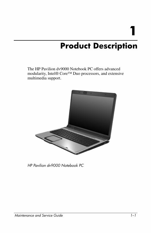
The HP Pavilion dv9000 Notebook PC offers advanced modularity, Intel® Core™ Duo processors, and extensive multimedia support.
HP Pavilion dv9000 Notebook PC
Maintenance and Service Guide 1–1
Product Description
1.1 Features■ The following processors are available, varying by
computer model:
❏ Intel Core Duo T7200 (2.00-GHz)
❏ Intel Core Duo T5600 (1.83-GHz)
❏ Intel Core Duo T5500 (1.66-GHz)
❏ Intel Core Duo T5300 (1.73-GHz)
❏ Intel Core Duo T5200 (1.66-GHz)
❏ Intel Core Duo T2250 (1.66-GHz)
❏ Intel Core Duo T2350 (1.86-GHz)
❏ Intel Core Duo T2300E (1.66-GHz)
❏ Intel Pentium Dual-Core T2080 (1.73-GHz)
❏ AMD Turion TL-64 2.2-GHz
❏ AMD Turion TL-60 2.0-GHz
❏ AMD Turion TL-58 1.9-GHz
❏ AMD Turion TL-56 1.8-GHz
❏ AMD Athlon 64 TK-53 (1.7-GHz)
■ The following displays are available, varying by computer model:
❏ 17.0-inch WSXGA+ BrightView (1680 × 1050) TFT display with over 16.7 million colors
❏ 17.0-inch WXGA+ BrightView (1440 × 900) TFT display with over 16.7 million colors
■ 200-, 160-, 120-, 100-, or 80-GB high-capacity hard drive, varying by computer model
■ 512-MB DDR synchronous DRAM (SDRAM) at 667 MHz, expandable to 2.0 GB
■ Microsoft® Windows Vista™ Business, Windows Vista Home Basic, and Windows® XP Professional
■ Full-size Windows keyboard with numeric keypad
1–2 Maintenance and Service Guide
Product Description
■ TouchPad pointing device with on/off button and dedicated two-way scroll zone
■ Integrated 10/100/1000 Gigabit Ethernet local area network (LAN) network interface card (NIC) with RJ-45 jack, varying by computer model
■ Integrated high-speed 56K modem with RJ-11 jack
■ Integrated wireless support for Mini Card IEEE 802.11a/b/g and 802.11b/g WLAN devices
■ Support for ExpressCard
■ External 90-watt AC adapter with 3-wire power cord
■ 8-cell Li-Ion battery
■ Stereo speakers with volume control buttons
■ Integrated 1.3-megapixel camera
■ Integrated microphones (select models only)
■ Support for the following optical drives:
❏ DVD±RW/R and CD-RW Double-Layer Combo Drive with LightScribe
❏ DVD±RW/R and CD-RW Double-Layer Combo Drive
■ Connectors:
❏ Audio-in (microphone)
❏ Audio-out (headphone, 2)
❏ Consumer infrared lens
❏ Expansion port 3
❏ ExpressCard
❏ External monitor
❏ IEEE 1394a digital
❏ Digital Media Slot
❏ Power
❏ RJ-11 (modem)
❏ RJ-45 (network)
Maintenance and Service Guide 1–3
Product Description
❏ S-Video-out
❏ Universal Serial Bus (USB) v. 2.0 (4 ports)
1.2 Resetting the ComputerIf the computer you are servicing has an unknown password, follow these steps to clear the password. These steps also clear CMOS:
1. Prepare the computer for disassembly (refer to Section 5.3, “Preparing the Computer For Disassembly,” for more information).
2. Remove the real-time clock (RTC) battery (refer toSection 5.7, “RTC Battery,” for more information).
3. Wait approximately 5 minutes.
4. Replace the RTC battery and reassemble the computer.
5. Connect AC power to the computer. Do not reinsert any batteries at this time.
6. Turn on the computer.
All passwords and all CMOS settings have been cleared.
1–4 Maintenance and Service Guide
Product Description
1.3 Power ManagementThe computer comes with power management features that extend battery operating time and conserve power. The computer supports the following power management features:
■ Standby
■ Hibernation
■ Setting customization by the user
■ Hotkeys for setting the level of performance
■ Battery calibration
■ Lid switch standby/resume
■ Power button
■ Advanced Configuration and Power Management (ACPM) compliance
Maintenance and Service Guide 1–5

Product Description
1.4 External ComponentsThe external components on the front of the computer are shown below and described in Table 1-1.
Front Components
Table 1-1
Front Components
Item Component Function
1 Power light On: The computer is on.Blinking: The computer is in standby.Off: The computer is off or in hibernation.
2 Battery light On: A battery is charging.Blinking: A battery that is the only available power source has reached a low-battery condition. When the battery reaches a critical low-battery condition, the battery light begins blinking rapidly.Off: If the computer is plugged into an external power source, the light is turned off when all batteries in the computer are fully charged. If the computer is not plugged into an external power source, the light stays off until the battery reaches a low-battery condition.
1–6 Maintenance and Service Guide
Product Description
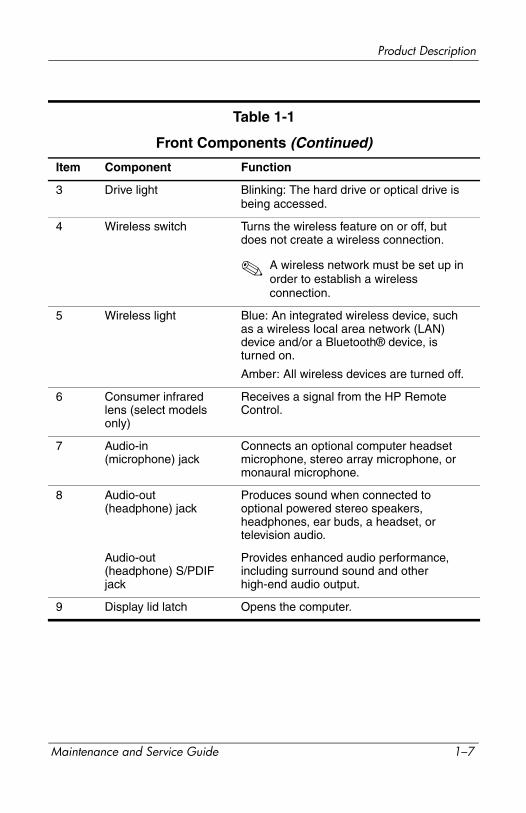
3 Drive light Blinking: The hard drive or optical drive is being accessed.
4 Wireless switch Turns the wireless feature on or off, but does not create a wireless connection.
✎ A wireless network must be set up in order to establish a wireless connection.
5 Wireless light Blue: An integrated wireless device, such as a wireless local area network (LAN) device and/or a Bluetooth® device, is turned on.
Amber: All wireless devices are turned off.
6 Consumer infrared lens (select models only)
Receives a signal from the HP Remote Control.
7 Audio-in (microphone) jack
Connects an optional computer headset microphone, stereo array microphone, or monaural microphone.
8 Audio-out (headphone) jack
Produces sound when connected to optional powered stereo speakers, headphones, ear buds, a headset, or television audio.
Audio-out (headphone) S/PDIF jack
Provides enhanced audio performance, including surround sound and other high-end audio output.
9 Display lid latch Opens the computer.
Table 1-1
Front Components (Continued)
Item Component Function
Maintenance and Service Guide 1–7

Product Description
The external components on the left side of the computer are shown below and described in Table 1-2.
Left-Side Components
Table 1-2
Left-Side Components
Item Component Function
1 Security cable slot Attaches an optional security cable to the computer.
✎ The security cable is designed to act as a deterrent, but it may not prevent the computer from being mishandled or stolen.
2 S-Video-out jack Connects an optional S-Video device such as a television, VCR, camcorder, overhead projector, or video capture card.
3 External monitor port Connects an external VGA monitor or projector.
1–8 Maintenance and Service Guide

Product Description
4 Expansion port 3 Connects the computer to an optional expansion product.
✎ The computer has only one expansion port. The term expansion port 3 describes the type of expansion port.
5 RJ-45 (network) jack Connects a network cable.
✎ The RJ-45 (network) jack provides Gigabit Ethernet functionality.
6 RJ-11 (modem) jack Connects a modem cable.
7 HDMI port (select models only)
Connects an optional audio or video device such as a high-definition television, set-top box, DVD player, or any compatible digital or audio device.
8 USB ports (2) Connect optional USB devices.
9 1394 port Connects an optional IEEE 1394 or 1394a device, such as a camcorder.
10 Digital Media Slot light On: A digital card is being accessed.
11 Digital Media Slot Supports the following optional digital card formats: Secure Digital (SD) Memory Card, MultiMediaCard (MMC), Secure Digital Input/Output (SD I/O), Memory Stick (MS), Memory Stick Pro (MSP), xDPicture Card (XD), xD-Picture Card (XD) Type M.
Table 1-2
Left-Side Components (Continued)
Item Component Function
Maintenance and Service Guide 1–9
Product Description
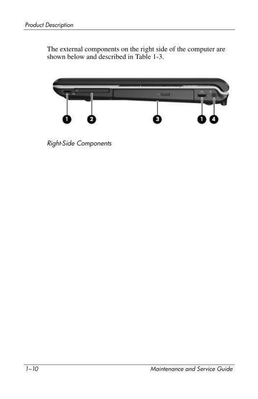
The external components on the right side of the computer are shown below and described in Table 1-3.
Right-Side Components
1–10 Maintenance and Service Guide
Product Description
Table 1-3
Right-Side Components
Item Component Function
1 USB ports (2) Connect optional USB devices.
2 ExpressCard slot Supports optional ExpressCard/54 cards.
3 Optical drive Reads an optical disc.
4 Power connector Connects an AC adapter.
Maintenance and Service Guide 1–11
Product Description
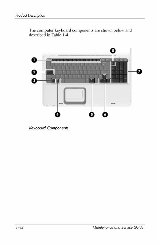
The computer keyboard components are shown below and described in Table 1-4.
Keyboard Components
1–12 Maintenance and Service Guide
Product Description
Table 1-4
Keyboard Components
Item Component Function
1 Function keys Execute frequently used system functions when pressed in combination with the fn key.
2 caps lock key Enables caps lock and turns on the caps lock light.
3 fn key Executes frequently used system functions when pressed in combination with a function key or the esc key.
4 Windows logo key Displays the Microsoft Windows Start menu.
5 Windows applications key
Displays a shortcut menu for items beneath the pointer.
6 Arrow keys Move the cursor around the screen.
7 Numeric keypad keys Can be used like the keys on an external numeric keypad.
8 num lock key Enables numeric lock, turns on the embedded numeric keypad, and turns on the num lock light.
Maintenance and Service Guide 1–13
Product Description
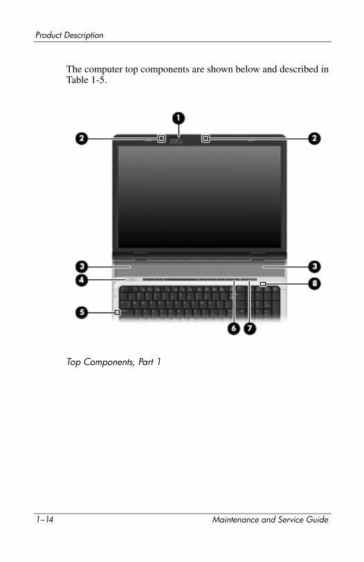
The computer top components are shown below and described in Table 1-5.
Top Components, Part 1
1–14 Maintenance and Service Guide
Product Description
Table 1-5
Top Components, Part 1
Item Component Function
1 Integrated camera (select models only)
Records video and captures still photos.
2 Internal microphones (2, select models only)
Record sound.
✎ A microphone icon next to each microphone opening indicates that the computer has internal microphones.
3 Speakers (2) Produce sound.
4 Power button When the computer is
■ Off, press to turn on the computer.
■ On, press to enter hibernation.
■ In standby, briefly press to exit standby.
■ In hibernation, briefly press to exit hibernation.
If the computer has stopped responding and Microsoft® Windows® shutdown procedures cannot be used, press and hold the power button for at least 5 seconds to turn off the computer.
5 Caps lock light On: Caps lock is on.
6 Volume mute button Mutes and restores speaker sound.
7 Volume scroll zone Adjusts speaker volume. Slide your finger to the left to decrease volume and to the right to increase volume. You can also tap the minus sign on the scroll zone to decrease volume, or tap the plus sign on the scroll zone to increase volume.
8 Num lock light On: Num lock is on.
Maintenance and Service Guide 1–15

Product Description
The computer top components are shown below and described in Table 1-6.
Top Components, Part 2
1–16 Maintenance and Service Guide
Product Description
Table 1-6
Top Components, Part 2
Item Component Function
1 Media button If QuickPlay is not installed and the computer is
■ On, opens the music program or Media menu, which allows you to select a multimedia program.
■ Off, does not function.
■ In standby, resumes from standby into Windows.
If QuickPlay is installed and the computer is
■ On, opens the music program or Media menu, which allows you to select a multimedia program.
■ Off, opens the music program or the Media menu, which allows you to select a multimedia program.
■ In standby, resumes from standby into Windows.
✎ The media button does not affect the procedure for restoring from hibernation.
2 DVD button When the computer is
✎ On, opens the default DVD program to start a DVD in the optical drive.
✎ Off, opens QuickPlay to start a DVD in the optical drive. If the QuickPlay software is not installed, the DVD button starts in Windows.
✎ In hibernation, opens QuickPlay to start a DVD in the optical drive. If QuickPlay is not installed, the computer resumes from hibernation.
Maintenance and Service Guide 1–17

Product Description
3 Previous/rewind button
When a disc is playing in the optical drive:
■ Plays the previous track or chapter, when pressed once.
■ Rewinds when pressed with the fn key.
4 Play/pause button When a disc is in the optical drive and is
■ Not playing, plays the disc.
■ Playing, pauses the disc.
5 Next/fast forward button
When a disc is playing in the optical drive:
■ Play the next track or chapter, when pressed once.
■ Fast forwards when pressed with the fn key.
6 Stop button When a disc is playing in the optical drive, stops the current disc activity.
Table 1-6
Top Components, Part 2 (Continued)
Item Component Function
1–18 Maintenance and Service Guide
Product Description
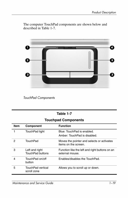
The computer TouchPad components are shown below and described in Table 1-7.
TouchPad Components
Table 1-7
Touchpad Components
Item Component Function
1 TouchPad light Blue: TouchPad is enabled.Amber: TouchPad is disabled.
2 TouchPad Moves the pointer and selects or activates items on the screen.
3 Left and right TouchPad buttons
Function like the left and right buttons on an external mouse.
4 TouchPad on/off button
Enables/disables the TouchPad.
5 TouchPad vertical scroll zone
Allows you to scroll up or down.
Maintenance and Service Guide 1–19
Product Description
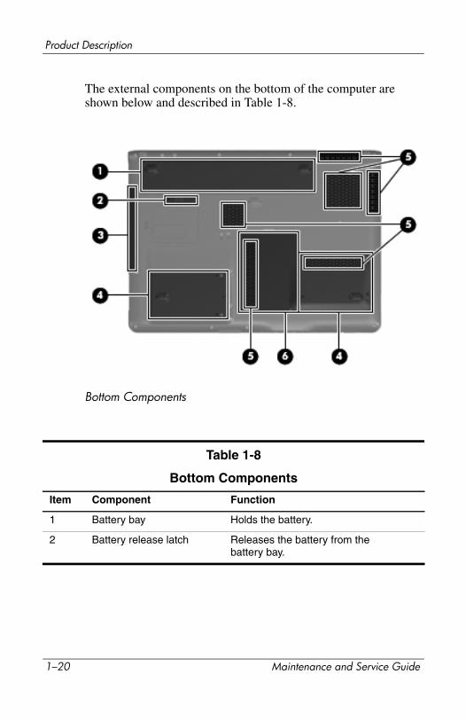
The external components on the bottom of the computer are shown below and described in Table 1-8.
Bottom Components
Table 1-8
Bottom Components
Item Component Function
1 Battery bay Holds the battery.
2 Battery release latch Releases the battery from the battery bay.
1–20 Maintenance and Service Guide
Product Description
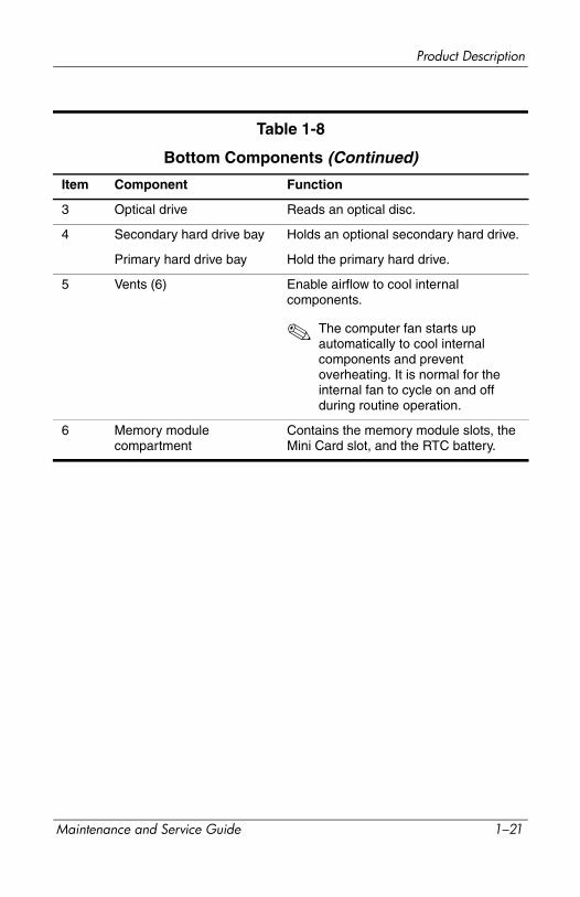
3 Optical drive Reads an optical disc.
4 Secondary hard drive bay Holds an optional secondary hard drive.
Primary hard drive bay Hold the primary hard drive.
5 Vents (6) Enable airflow to cool internal components.
✎ The computer fan starts up automatically to cool internal components and prevent overheating. It is normal for the internal fan to cycle on and off during routine operation.
6 Memory module compartment
Contains the memory module slots, the Mini Card slot, and the RTC battery.
Table 1-8
Bottom Components (Continued)
Item Component Function
Maintenance and Service Guide 1–21
Product Description
1.5 Design overviewThis section presents a design overview of key parts and features of the computer. Refer to Chapter 3, “Illustrated Parts Catalog,” to identify replacement parts, and Chapter 5, “Removal and Replacement Procedures,” for disassembly steps.
The system board provides the following device connections:
■ AMD Mobile Turion and Mobile AMD Athlon processors
■ Audio
■ Display
■ ExpressCard
■ Fan
■ Hard drive
■ Intel Core Duo processors
■ Keyboard and TouchPad
■ Memory module
■ Mini Card module
ÄCAUTION: To properly ventilate the computer, allow at least a 7.6-cm (3-inch) clearance on the left and right sides of the computer.
The computer uses an electric fan for ventilation. The fan is controlled by a temperature sensor and is designed to turn on automatically when high temperature conditions exist. These conditions are affected by high external temperatures, system power consumption, power management/battery conservation configurations, battery fast charging, and software. Exhaust air is displaced through the ventilation grill located on the left side of the computer.
1–22 Maintenance and Service Guide
2Troubleshooting
ÅWARNING: Only authorized technicians trained by HP should repair this equipment. All troubleshooting and repair procedures are detailed to allow only subassembly-/module-level repair. Because of the complexity of the individual boards and subassemblies, do not attempt to make repairs at the component level or modifications to any printed wiring board. Improper repairs can create a safety hazard. Any indication of component replacement or printed wiring board modification may void any warranty or exchange allowances.
2.1 Setup Utility in Windows XPThe Setup Utility is a ROM-based information and customization utility that can be used even when your Windows operating system is not working or will not load.
The utility reports information about the computer and provides settings for startup, security, and other preferences.
1. Turn on or restart the computer in Windows.
2. Before Windows opens and while the “Press <F10> to enter setup” prompt is displayed in the lower-left corner of the screen, press f10.
Using the Setup Utility
Changing the Language of the Setup UtilityThe following procedure explains how to change the language of the Setup Utility. If the computer is not in the Setup Utility, begin at step 1. If the computer is in the Setup Utility, begin at step 2.
Maintenance and Service Guide 2–1
Troubleshooting
1. To open the Setup Utility, turn on or restart the computer in Windows, and then press f10 while the prompt, “Press <F10> to enter setup,” is displayed in the lower-left corner of the screen.
2. Use the arrow keys to select System Configuration > Language, and then press enter.
3. Press f5 or f6 (or use the arrow keys) to select a language, and then press enter to select a language.
4. When a confirmation prompt with your preference selected is displayed, press enter to save your preference.
5. To set your preferences and exit the Setup Utility, press f10 and then follow the instructions on the screen.
Your preferences go into effect when the computer restarts in Windows.
Navigating and Selecting in the Setup UtilityBecause the Setup Utility is not Windows-based, it does not support the TouchPad. Navigation and selection are by keystroke.
■ To choose a menu or a menu item, use the arrow keys.
■ To choose an item in a drop-down list or to toggle a field, for example an Enable/Disable field, use either the arrow keys or f5 or f6.
■ To select an item, press enter.
■ To close a text box or return to the menu display, press f1.
■ To display additional navigation and selection information while the Setup Utility is open, press f1.
Displaying System InformationThe following procedure explains how to display system information in the Setup Utility. If the Setup Utility is not open, begin at step 1. If the Setup Utility is open, begin at step 2.
2–2 Maintenance and Service Guide
Troubleshooting
1. To start the Setup Utility, turn on or restart the computer in Windows, and then press f10 while the prompt, “Press <F10> to enter setup,” is displayed in the lower-left corner of the screen.
2. Access the system information by using the Main menu.
3. To close the Setup Utility without changing any settings, use the arrow keys to select Exit > Exit Discarding Changes, and then press enter. (The computer restarts in Windows.)
Restoring Default Settings in the Setup UtilityThe following procedure explains how to restore the Setup Utility default settings. If the computer is not in the Setup Utility, begin at step 1. If the computer is in the Setup Utility, begin at step 2.
1. To start the Setup Utility, turn on or restart the computer in Windows, and then press f10 while the prompt, “Press <F10> to enter setup,” is displayed in the lower-left corner of the screen.
2. Select Exit > Load Setup Defaults, and then press f10.
3. When the Setup Confirmation is displayed, press enter to save your preferences.
4. To set your preferences and exit the Setup Utility, press f10, and then follow the instructions on the screen.
The Setup Utility default settings are set when you exit the Setup Utility and go into effect when the computer restarts.
✎ Your password, security, and language settings are not changed when you restore the factory default settings.
Maintenance and Service Guide 2–3
Troubleshooting
Using Advanced Setup Utility FeaturesThis guide describes the Setup Utility features recommended for all users. For more information about the Setup Utility features recommended for advanced users only, refer to the Help and Support Center, which is accessible only when the computer is in Windows.
The Setup Utility features available for advanced users include a hard drive self-test, a Network Service Boot, and settings for boot order preferences.
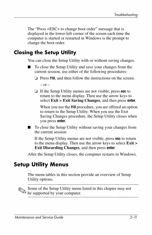
The “<F12> to boot from LAN” message that is displayed in the lower-left corner of the screen each time the computer is started or restarted in Windows or restored from hibernation is the prompt for a Network Service Boot.
The “Press <ESC> to change boot order” message that is displayed in the lower-left corner of the screen each time the computer is started or restarted in Windows or restored from hibernation is the prompt to change the boot order.
Closing the Setup UtilityYou can close the Setup Utility with or without saving changes.
■ To close the Setup Utility and save your changes from the current session, use either of the following procedures:
❏ Press f10, and then follow the instructions on the screen.
– or –
❏ If the Setup Utility menus are not visible, press esc to return to the menu display. Then use the arrow keys to select Exit > Exit Saving Changes, and then press enter.
When you use the f10 procedure, you are offered an option to return to the Setup Utility. When you use the Exit Saving Changes procedure, the Setup Utility closes when you press enter.
2–4 Maintenance and Service Guide
Troubleshooting
■ To close the Setup Utility without saving your changes from the current session:
If the Setup Utility menus are not visible, press esc to return to the menu display. Then use the arrow keys to select Exit > Exit Discarding Changes, and then press enter.
After the Setup Utility closes, the computer restarts in Windows.
Setup Utility Menus
The menu tables in this section provide an overview of Setup Utility options.
✎ Some of the Setup Utility menu listed in this chapter may not be supported by your computer.
Main Menu
Table 2-1
Main Menu
Select To Do This
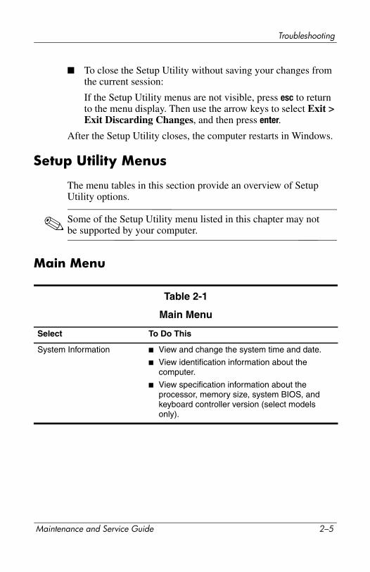
System Information ■ View and change the system time and date.
■ View identification information about the computer.
■ View specification information about the processor, memory size, system BIOS, and keyboard controller version (select models only).
Maintenance and Service Guide 2–5
Troubleshooting
Security Menu
System Configuration Menu
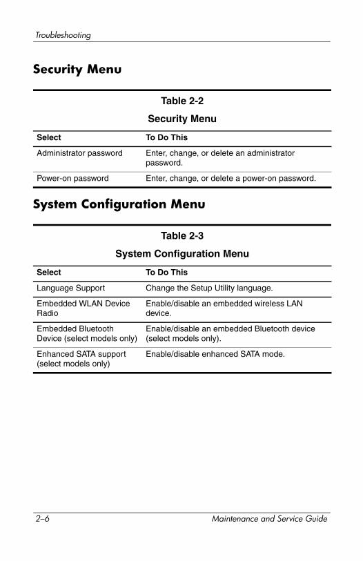
Table 2-2
Security Menu
Select To Do This
Administrator password Enter, change, or delete an administrator password.
Power-on password Enter, change, or delete a power-on password.
Table 2-3
System Configuration Menu
Select To Do This
Language Support Change the Setup Utility language.
Embedded WLAN Device Radio
Enable/disable an embedded wireless LAN device.
Embedded Bluetooth Device (select models only)
Enable/disable an embedded Bluetooth device (select models only).
Enhanced SATA support (select models only)
Enable/disable enhanced SATA mode.
2–6 Maintenance and Service Guide

Troubleshooting
Diagnostics Menu
Boot Options Set the following boot options:
■ f10 and f12 Delay (sec.)—Set the delay for the f10 and f12 functions of the Setup Utility in intervals of 5 seconds each (0, 5, 10, 15, 20).
■ CD-ROM boot—Enable/disable boot from CD-ROM.
■ Floppy boot—Enable/disable boot from Floppy.
■ Internal Network Adapter boot—Enable/disable boot from Internal Network Adapter.
■ Boot Order—Set the boot order for:
❐ USB Floppy
❐ ATAPI CD/DVD ROM Drive
❐ Hard drive❐ USB Diskette on Key
❐ USB Hard drive
❐ Network adapter
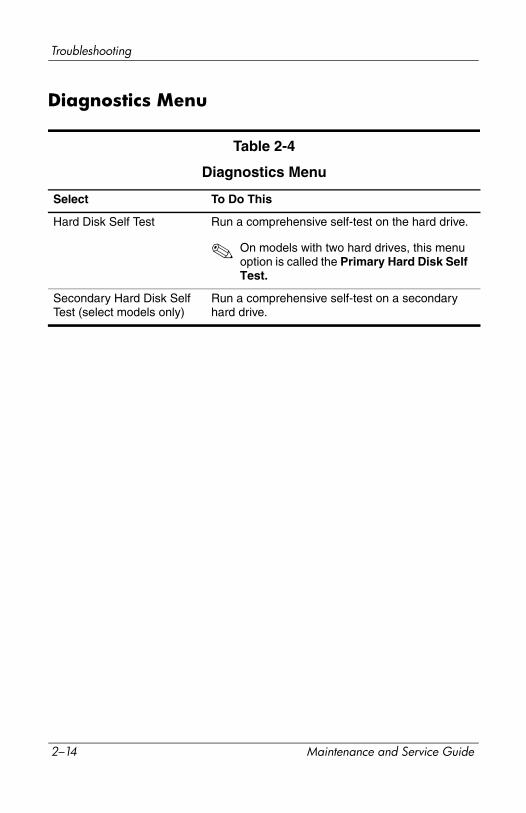
Table 2-4
Diagnostics Menu
Select To Do This
Hard Disk Self Test Run a comprehensive self-test on the hard drive.
Table 2-3
System Configuration Menu (Continued)
Select To Do This
Maintenance and Service Guide 2–7
Troubleshooting
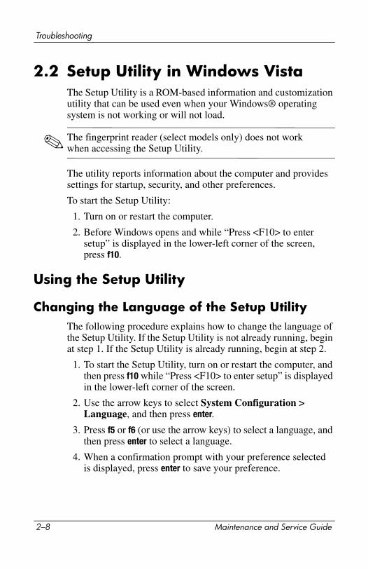
2.2 Setup Utility in Windows VistaThe Setup Utility is a ROM-based information and customization utility that can be used even when your Windows® operating system is not working or will not load.
✎ The fingerprint reader (select models only) does not work when accessing the Setup Utility.
The utility reports information about the computer and provides settings for startup, security, and other preferences.
To start the Setup Utility:
1. Turn on or restart the computer.
2. Before Windows opens and while “Press <F10> to enter setup” is displayed in the lower-left corner of the screen, press f10.
Using the Setup Utility
Changing the Language of the Setup UtilityThe following procedure explains how to change the language of the Setup Utility. If the Setup Utility is not already running, begin at step 1. If the Setup Utility is already running, begin at step 2.
1. To start the Setup Utility, turn on or restart the computer, and then press f10 while “Press <F10> to enter setup” is displayed in the lower-left corner of the screen.
2. Use the arrow keys to select System Configuration > Language, and then press enter.
3. Press f5 or f6 (or use the arrow keys) to select a language, and then press enter to select a language.
4. When a confirmation prompt with your preference selected is displayed, press enter to save your preference.
2–8 Maintenance and Service Guide

Troubleshooting
5. To set your preferences and exit the Setup Utility, press f10 and then follow the instructions on the screen.
Your preferences go into effect when the computer restarts in Windows.
Navigating and Selecting in the Setup UtilityBecause the Setup Utility is not Windows-based, it does not support the TouchPad. Navigation and selection are by keystroke.
■ To choose a menu or a menu item, use the arrow keys.
■ To choose an item in a drop-down list or to toggle a field, for example an Enable/Disable field, use either the arrow keys or f5 or f6.
■ To select an item, press enter.
■ To close a text box or return to the menu display, press esc.
■ To display additional navigation and selection information while the Setup Utility is open, press f1.
Displaying System InformationThe following procedure explains how to display system information in the Setup Utility. If the Setup Utility is not open, begin at step 1. If the Setup Utility is open, begin at step 2.
1. To start the Setup Utility, turn on or restart the computer, and then press f10 while “Press <F10> to enter setup” is displayed in the lower-left corner of the screen.
2. Access the system information by using the Main menu.
3. To exit the Setup Utility without changing any settings, use the arrow keys to select Exit > Exit Discarding Changes, and then press enter. (The computer restarts in Windows.)
Maintenance and Service Guide 2–9

Troubleshooting
Restoring Default Settings in the Setup UtilityThe following procedure explains how to restore the Setup Utility default settings. If the Setup Utility is not already running, begin at step 1. If the Setup Utility is already running, begin at step 2.
1. To start the Setup Utility, turn on or restart the computer, and then press f10 while “Press <F10> to enter setup” is displayed in the lower-left corner of the screen.
2. Select Exit > Load Setup Defaults, and then press enter.
3. When the Setup Confirmation is displayed, press enter to save your preferences.
4. To set your preferences and exit the Setup Utility, press f10, and then follow the instructions on the screen.
The Setup Utility default settings are set when you exit the Setup Utility and go into effect when the computer restarts.
✎ Your password, security, and language settings are not changed when you restore the factory default settings.
Using Advanced Setup Utility FeaturesThis guide describes the Setup Utility features recommended for all users. For more information about the Setup Utility features recommended for advanced users only, refer to Help and Support, which is accessible only when the computer is in Windows.
The Setup Utility features available for advanced users include a hard drive self-test, a Network Service Boot, and settings for boot order preferences.
The “<F12> to boot from LAN” message that is displayed in the lower-left corner of the screen each time the computer is started or restarted in Windows is the prompt for a Network Service Boot.
2–10 Maintenance and Service Guide
Troubleshooting
The “Press <ESC> to change boot order” message that is displayed in the lower-left corner of the screen each time the computer is started or restarted in Windows is the prompt to change the boot order.
Closing the Setup UtilityYou can close the Setup Utility with or without saving changes.
■ To close the Setup Utility and save your changes from the current session, use either of the following procedures:
❏ Press f10, and then follow the instructions on the screen.
– or –
❏ If the Setup Utility menus are not visible, press esc to return to the menu display. Then use the arrow keys to select Exit > Exit Saving Changes, and then press enter.
When you use the f10 procedure, you are offered an option to return to the Setup Utility. When you use the Exit Saving Changes procedure, the Setup Utility closes when you press enter.
■ To close the Setup Utility without saving your changes from the current session:
If the Setup Utility menus are not visible, press esc to return to the menu display. Then use the arrow keys to select Exit > Exit Discarding Changes, and then press enter.
After the Setup Utility closes, the computer restarts in Windows.
Setup Utility Menus
The menu tables in this section provide an overview of Setup Utility options.
✎ Some of the Setup Utility menu listed in this chapter may not be supported by your computer.
Maintenance and Service Guide 2–11
Troubleshooting
Main Menu
Security Menu
System Configuration Menu
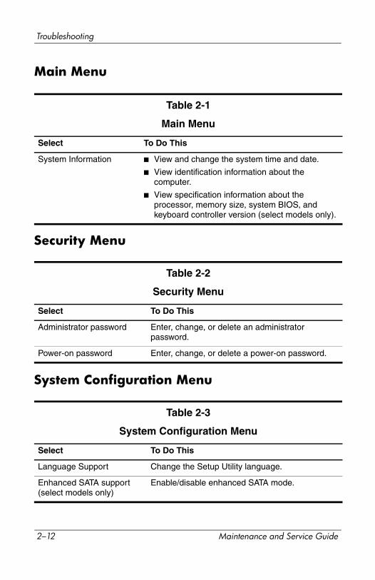
Table 2-1
Main Menu
Select To Do This
System Information ■ View and change the system time and date.
■ View identification information about the computer.
■ View specification information about the processor, memory size, system BIOS, and keyboard controller version (select models only).
Table 2-2
Security Menu
Select To Do This
Administrator password Enter, change, or delete an administrator password.
Power-on password Enter, change, or delete a power-on password.
Table 2-3
System Configuration Menu
Select To Do This
Language Support Change the Setup Utility language.
Enhanced SATA support (select models only)
Enable/disable enhanced SATA mode.
2–12 Maintenance and Service Guide

Troubleshooting
Boot Options Set the following boot options:
■ f10 and f12 Delay (sec.)—Set the delay for the f10 and f12 functions of the Setup Utility in intervals of 5 seconds each (0, 5, 10, 15, 20).
■ CD-ROM boot—Enable/disable boot from CD-ROM.
■ Floppy boot—Enable/disable boot from Floppy.
■ Internal Network Adapter boot—Enable/disable boot from Internal Network Adapter.
■ Boot Order—Set the boot order for:
❐ USB Floppy
❐ ATAPI CD/DVD ROM Drive
❐ Hard drive❐ USB Diskette on Key
❐ USB Hard drive
❐ Network adapter
Button Sound (select models only)
Enable/disable the Quick Launch Button tapping sound.
Video memory up to (select models only)
Select the amount of video memory.
Table 2-3
System Configuration Menu
Select To Do This
Maintenance and Service Guide 2–13
Troubleshooting
Diagnostics Menu
Table 2-4
Diagnostics Menu
Select To Do This
Hard Disk Self Test Run a comprehensive self-test on the hard drive.
✎ On models with two hard drives, this menu option is called the Primary Hard Disk Self Test.
Secondary Hard Disk Self Test (select models only)
Run a comprehensive self-test on a secondary hard drive.
2–14 Maintenance and Service Guide
Troubleshooting
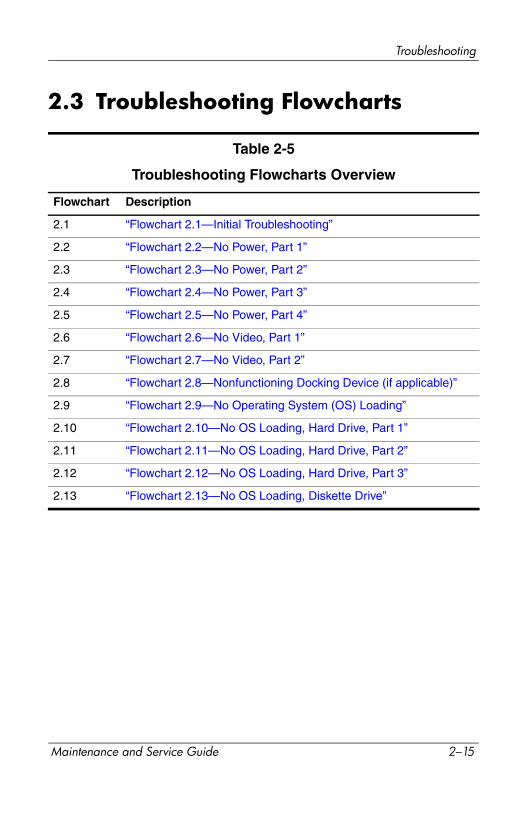
2.3 Troubleshooting Flowcharts
Table 2-5
Troubleshooting Flowcharts Overview
Flowchart Description
2.1 “Flowchart 2.1—Initial Troubleshooting”
2.2 “Flowchart 2.2—No Power, Part 1”
2.3 “Flowchart 2.3—No Power, Part 2”
2.4 “Flowchart 2.4—No Power, Part 3”
2.5 “Flowchart 2.5—No Power, Part 4”
2.6 “Flowchart 2.6—No Video, Part 1”
2.7 “Flowchart 2.7—No Video, Part 2”
2.8 “Flowchart 2.8—Nonfunctioning Docking Device (if applicable)”
2.9 “Flowchart 2.9—No Operating System (OS) Loading”
2.10 “Flowchart 2.10—No OS Loading, Hard Drive, Part 1”
2.11 “Flowchart 2.11—No OS Loading, Hard Drive, Part 2”
2.12 “Flowchart 2.12—No OS Loading, Hard Drive, Part 3”
2.13 “Flowchart 2.13—No OS Loading, Diskette Drive”
Maintenance and Service Guide 2–15
Troubleshooting
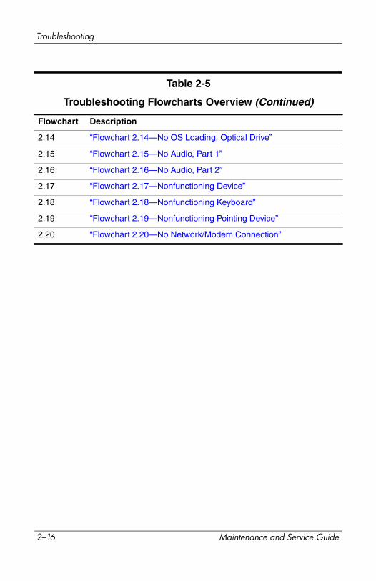
Flowchart Description
2.14 “Flowchart 2.14—No OS Loading, Optical Drive”
2.15 “Flowchart 2.15—No Audio, Part 1”
2.16 “Flowchart 2.16—No Audio, Part 2”
2.17 “Flowchart 2.17—Nonfunctioning Device”
2.18 “Flowchart 2.18—Nonfunctioning Keyboard”
2.19 “Flowchart 2.19—Nonfunctioning Pointing Device”
2.20 “Flowchart 2.20—No Network/Modem Connection”
Table 2-5
Troubleshooting Flowcharts Overview (Continued)
2–16 Maintenance and Service Guide
Troubleshooting
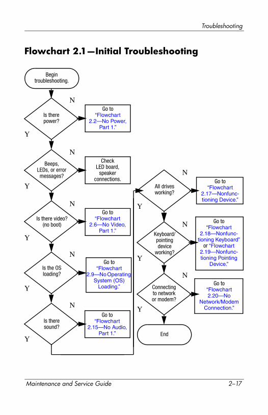
Flowchart 2.1—Initial Troubleshooting
Connectingto networkor modem?
Begintroubleshooting.
Is therepower?
Is the OSloading?
Is there video?(no boot)
Is theresound?
Beeps,LEDs, or errormessages?
Keyboard/pointingdevice
working?
Go to“Flowchart
2.17—Nonfunc-tioning Device.”
Go to“Flowchart
2.2—No Power, Part 1.”
Go to“Flowchart
2.6—No Video, Part 1.”
All drivesworking?
Y
Y
Y
Y
Y
Y
Y
Y
N
N
N
N
N
End
N
N
N
Go to“Flowchart
2.9—No Operating System (OS)
Loading.”
Go to“Flowchart
2.15—No Audio, Part 1.”
Go to“Flowchart
2.18—Nonfunc-tioning Keyboard”
or “Flowchart 2.19—Nonfunc-tioning Pointing
Device.”
CheckLED board,
speakerconnections.
Go to“Flowchart 2.20—No
Network/Modem Connection.”
Maintenance and Service Guide 2–17
Troubleshooting
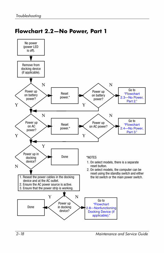
Flowchart 2.2—No Power, Part 1
1. Reseat the power cables in the docking device and at the AC outlet.
2. Ensure the AC power source is active.3. Ensure that the power strip is working.
Done
Remove fromdocking device(if applicable).
Power upon battery
power?
Power upon AC
power?
Power up in docking device?
Power upon battery
power?
Power upin docking
device?
Done
Reset power.*
Reset power.*
Power upon AC power?
N
Y
Y
N
N
Y
N
N
Y
Y
Y N
1. On select models, there is a separate reset button.
2. On select models, the computer can be reset using the standby switch and either the lid switch or the main power switch.
*NOTES
Go to“Flowchart
2.4—No Power, Part 3.”
Go to“Flowchart
2.3—No Power, Part 2.”
Go to“Flowchart
2.8—Nonfunctioning Docking Device (if
applicable).”
No power (power LED
is off).
2–18 Maintenance and Service Guide
Troubleshooting
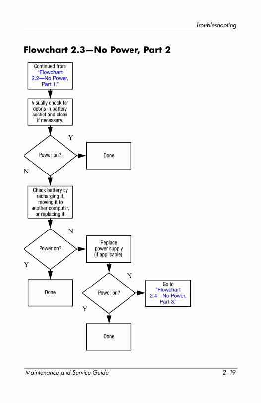
Flowchart 2.3—No Power, Part 2
Continued from“Flowchart
2.2—No Power, Part 1.”
Visually check fordebris in batterysocket and clean
if necessary.
Done
N
Y
Power on?
Check battery byrecharging it,moving it to
another computer,or replacing it.
Power on?
Done
Y
Replacepower supply(if applicable).
N
Power on?
Done
Y
NGo to
“Flowchart 2.4—No Power,
Part 3.”
Maintenance and Service Guide 2–19
Troubleshooting
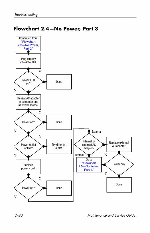
Flowchart 2.4—No Power, Part 3
Continued from“Flowchart
2.3—No Power, Part 2.”
Reseat AC adapterin computer andat power source.
Internal orexternal AC
adapter?
Done
Done
DoneDone
Power on?
Power on?
Power on?
Plug directlyinto AC outlet.
Power LEDon?
Power outletactive?
Try differentoutlet.
Replace externalAC adapter.
Replacepower cord.
Y
N
Y
Y
Y
Y
N
N
N
N
External
InternalGo to
“Flowchart 2.5—No Power,
Part 4.”
2–20 Maintenance and Service Guide

Troubleshooting
Flowchart 2.5—No Power, Part 4
Y
N
Continued from“Flowchart
2.4—No Power, Part 3.”
Reseat loosecomponents and
boards and replace damaged
items.
Opencomputer.
Loose ordamaged
parts?
Y
Closecomputer and
retest.
Power on?
Done
N
Replace the following items (if applicable). Check computer operation after each replacement:1. Internal DC-DC converter*2. Internal AC adapter3. Processor board*4. System board*
*NOTE: Replace these items as a set to prevent shorting out among components.
Maintenance and Service Guide 2–21
Troubleshooting
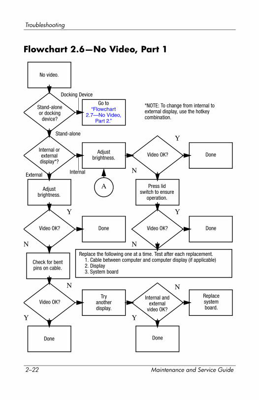
Flowchart 2.6—No Video, Part 1
A
N
Stand-aloneor docking
device?
No video.
Replace the following one at a time. Test after each replacement.1. Cable between computer and computer display (if applicable)2. Display3. System board
Internal orexternaldisplay*?
Adjustbrightness. Video OK? Done
Docking Device
Internal
Stand-alone
External
Adjustbrightness.
Video OK? Done
Y
Press lidswitch to ensure
operation.
Video OK? Done
Y
N
Video OK?
Done Done
N
Check for bentpins on cable.
Tryanotherdisplay.
Internal andexternal
video OK?
Replacesystemboard.
Y Y
NN
*NOTE: To change from internal to external display, use the hotkey combination.
Y
Go to“Flowchart
2.7—No Video, Part 2.”
2–22 Maintenance and Service Guide

Troubleshooting
Flowchart 2.7—No Video, Part 2
Y
N
Continued from“Flowchart
2.6—No Video, Part 1.”
Done
Adjust externalmonitor display.
Video OK?
Adjustdisplay
brightness.
Video OK?
Video OK?
Done
Done
Check that computer is properlyseated in docking device,
for bent pins on cable,and for monitor connection.
Go to “A” in“Flowchart
2.6—No Video, Part 1.”
Check brightnessof externalmonitor.
Try anotherexternalmonitor.
Internaland externalvideo OK?
Go to“Flowchart
2.8—Nonfunctioning Docking Device (if
applicable).”
Y
Y
Y
N
N
N
Remove computer from docking device,
if connected.
Maintenance and Service Guide 2–23
Troubleshooting
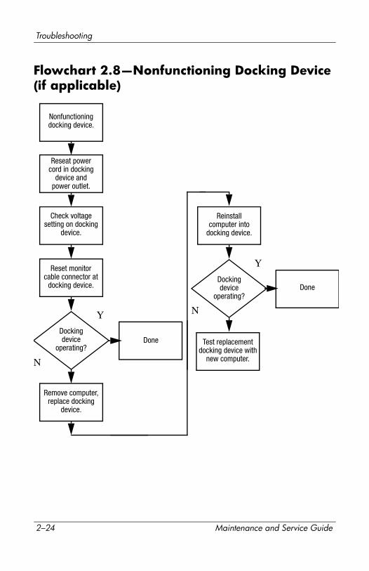
Flowchart 2.8—Nonfunctioning Docking Device(if applicable)
Y
N
Reseat power cord in docking
device andpower outlet.
N
Check voltagesetting on docking
device.
Reset monitorcable connector at
docking device.
Reinstallcomputer into
docking device.
Docking device
operating?
Docking device
operating?Done
Done
Y
Nonfunctioningdocking device.
Remove computer, replace docking
device.
Test replacement docking device with
new computer.
2–24 Maintenance and Service Guide
Troubleshooting
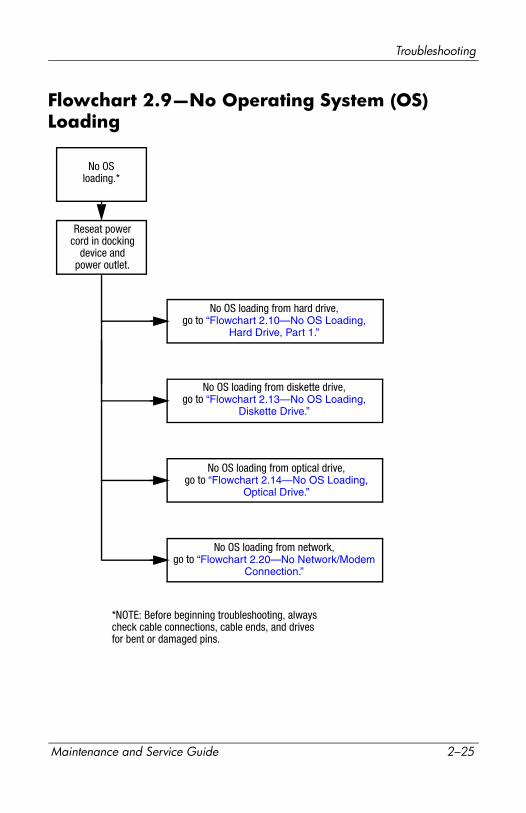
Flowchart 2.9—No Operating System (OS) Loading
No OS loading from hard drive,go to “Flowchart 2.10—No OS Loading,
Hard Drive, Part 1.”
Reseat powercord in docking
device andpower outlet.
No OSloading.*
*NOTE: Before beginning troubleshooting, always check cable connections, cable ends, and drives for bent or damaged pins.
No OS loading from diskette drive,go to “Flowchart 2.13—No OS Loading,
Diskette Drive.”
No OS loading from optical drive,go to “Flowchart 2.14—No OS Loading,
Optical Drive.”
No OS loading from network,go to “Flowchart 2.20—No Network/Modem
Connection.”
Maintenance and Service Guide 2–25
Troubleshooting
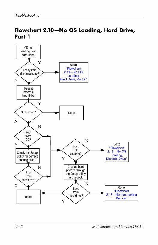
Flowchart 2.10—No OS Loading, Hard Drive, Part 1
Go to“Flowchart
2.17—Nonfunctioning Device.”
Y
Done
N
OS notloading fromhard drive.
Nonsystemdisk message?
Go to“Flowchart
2.11—No OS Loading,
Hard Drive, Part 2.”
Reseatexternal
hard drive.
OS loading? Done
BootfromCD?
Go to“Flowchart
2.13—No OS Loading,
Diskette Drive.”
Bootfrom
hard drive?
Bootfrom
diskette?
Change bootpriority throughthe Setup Utility
and reboot.
Bootfrom
hard drive?
Y
Y
Y
Y
Y
N
N
N
N
N
Check the Setuputility for correct
booting order.
2–26 Maintenance and Service Guide
Troubleshooting
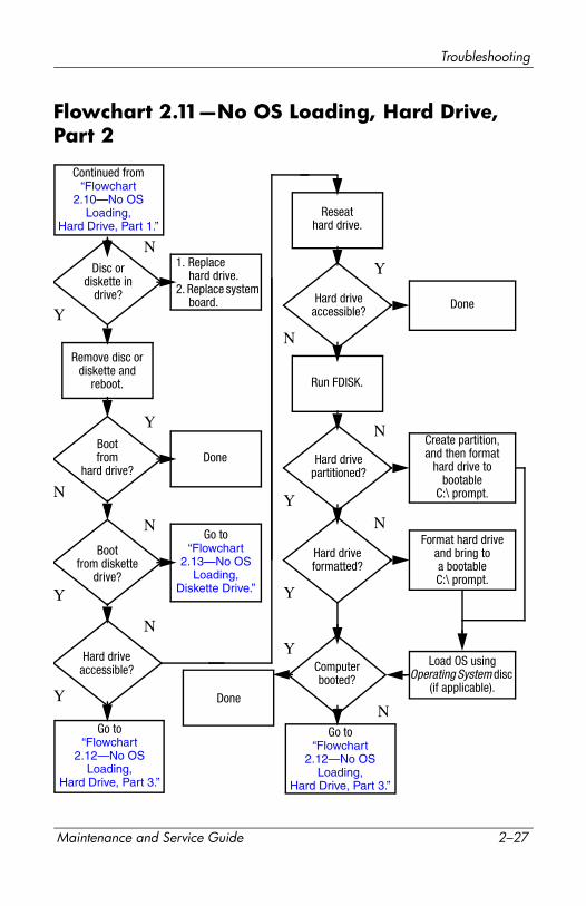
Flowchart 2.11—No OS Loading, Hard Drive, Part 2
Load OS using Operating System disc
(if applicable).
Continued from“Flowchart
2.10—No OS Loading,
Hard Drive, Part 1.”Reseat
hard drive.
Done
Disc ordiskette in
drive?
1. Replace hard drive.
2. Replace system board.
Go to“Flowchart
2.13—No OS Loading,
Diskette Drive.”
Format hard driveand bring toa bootableC:\ prompt.
Create partition, and then format
hard drive to bootable
C:\ prompt.
Bootfrom diskette
drive?
Remove disc ordiskette and
reboot.
Y
N
Bootfrom
hard drive?
Y
N
Y
N
Hard drive accessible?
Y
N
Hard driveaccessible?
Done
Run FDISK.
Y
N
Hard drivepartitioned?
Hard driveformatted?
Y
N
Y
N
Computerbooted?
Done
Y
NGo to
“Flowchart 2.12—No OS
Loading, Hard Drive, Part 3.”
Go to“Flowchart
2.12—No OS Loading,
Hard Drive, Part 3.”
Maintenance and Service Guide 2–27
Troubleshooting
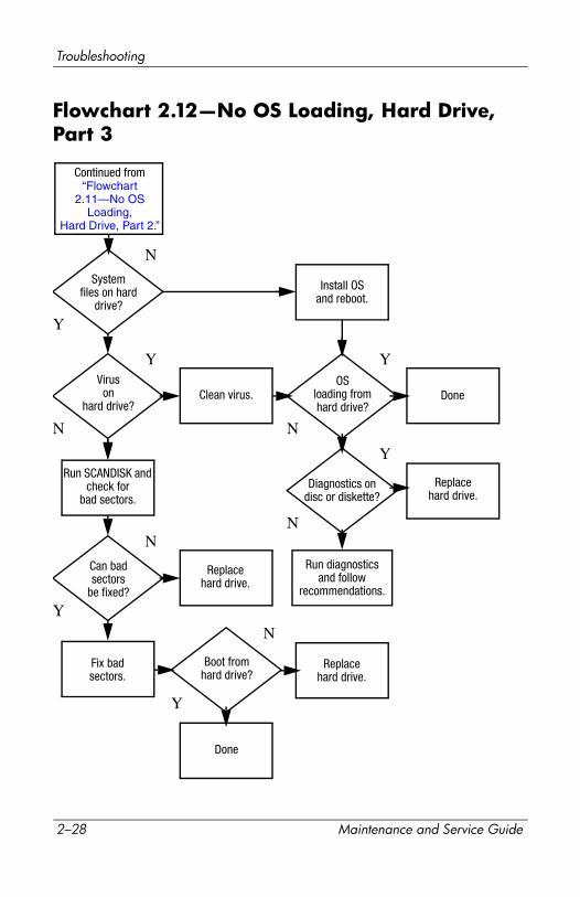
Flowchart 2.12—No OS Loading, Hard Drive, Part 3
Y
Systemfiles on hard
drive?
Continued from“Flowchart
2.11—No OS Loading,
Hard Drive, Part 2.”
Clean virus. Done
N
Install OSand reboot.
Viruson
hard drive?
OSloading fromhard drive?
Y
N
Y
N
Y
N
Diagnostics on disc or diskette?
Replacehard drive.
Run diagnosticsand follow
recommendations.
Run SCANDISK and check for
bad sectors.
Can badsectors
be fixed?
Replacehard drive.
Y
N
Y
N
Fix badsectors.
Boot fromhard drive?
Replacehard drive.
Done
2–28 Maintenance and Service Guide
Troubleshooting
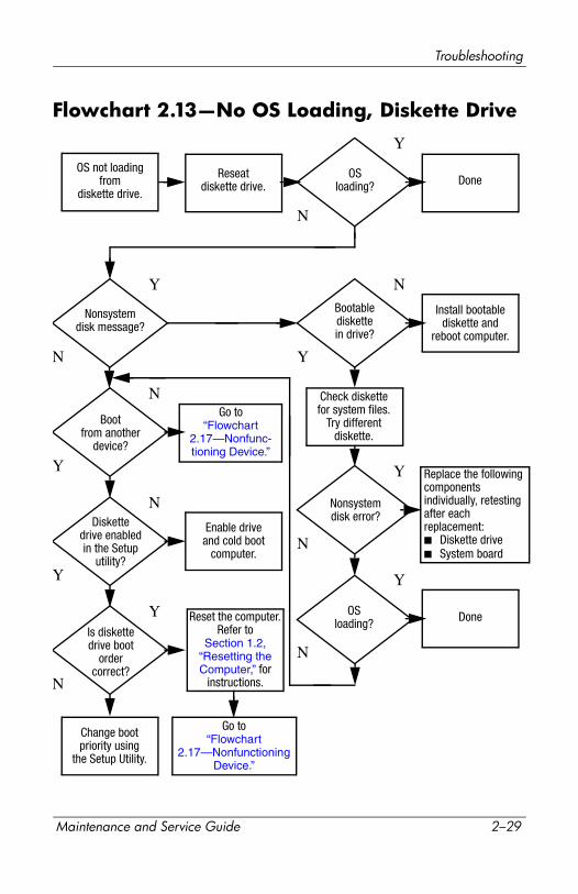
Flowchart 2.13—No OS Loading, Diskette Drive
Replace the following components individually, retesting after each replacement:■ Diskette drive■ System board
Done
Y
N
Reseatdiskette drive.
OS not loadingfrom
diskette drive.
Done
Y
Y
YY
Y Y
YN
N
N
N
N
N
N
OSloading?
Nonsystemdisk message?
Bootablediskettein drive?
Install bootablediskette and
reboot computer.
Check diskettefor system files.
Try differentdiskette.
Nonsystemdisk error?
OSloading?
Bootfrom another
device?
Enable driveand cold boot
computer.
Is diskettedrive boot
order correct?
Change bootpriority using
the Setup Utility.
Go to“Flowchart
2.17—Nonfunc-tioning Device.”
Diskettedrive enabledin the Setup
utility?
Go to“Flowchart
2.17—Nonfunctioning Device.”
Reset the computer. Refer to
Section 1.2, “Resetting the Computer,” for
instructions.
Maintenance and Service Guide 2–29

Troubleshooting
Flowchart 2.14—No OS Loading, Optical Drive
Y
Done
N
Bootabledisc indrive?
Discin drive?
No OSloading fromCD-ROM or
DVD-ROM drive.
Install bootabledisc andreboot
computer.
Go to“Flowchart
2.17—Nonfunctioning Device.”
Go to“Flowchart
2.17—Nonfunctioning Device.”
Installbootable disc.
Boots fromCD or DVD?
Boots fromCD or DVD?
Try anotherbootable disc.
Bootingfrom another
device?
Bootingorder
correct?
Correct bootorder using
the Setup Utility.
DoneReseatdrive.
Y
Y
Y
Y
Y
N
N
N
N
N
Reset the computer. Refer to
Section 1.2, “Resetting the Computer,” for
instructions.
2–30 Maintenance and Service Guide
Troubleshooting
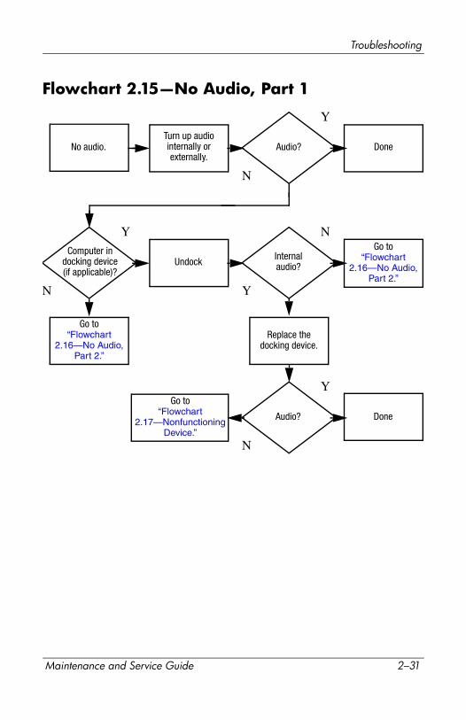
Flowchart 2.15—No Audio, Part 1
No audio.
N
Computer indocking device(if applicable)?
Internalaudio?
Audio? Done
Undock
Audio? Done
Turn up audiointernally orexternally.
Go to“Flowchart
2.16—No Audio, Part 2.”
Go to“Flowchart
2.17—Nonfunctioning Device.”
Y
Y
Y
Y
N
N
N
Go to“Flowchart
2.16—No Audio, Part 2.”
Replace the docking device.
Maintenance and Service Guide 2–31
Troubleshooting
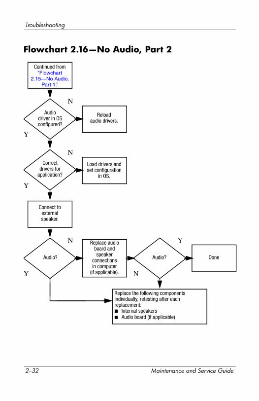
Flowchart 2.16—No Audio, Part 2
Y N
Continued from “Flowchart
2.15—No Audio, Part 1.”
Reloadaudio drivers.
Audiodriver in OSconfigured?
Audio?
Y
Y
YN
N
N
Correctdrivers for
application?
Connect toexternalspeaker.
Load drivers andset configuration
in OS.
Audio? Done
Replace audioboard andspeaker
connectionsin computer
(if applicable).
Replace the following components individually, retesting after each replacement:■ Internal speakers■ Audio board (if applicable)
2–32 Maintenance and Service Guide
Troubleshooting
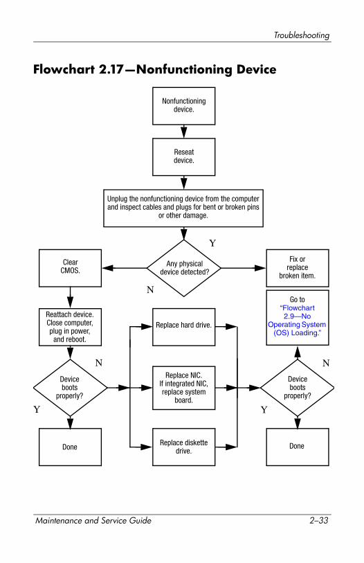
Flowchart 2.17—Nonfunctioning Device
Done
Any physicaldevice detected?
Y
N
Unplug the nonfunctioning device from the computer and inspect cables and plugs for bent or broken pins
or other damage.
Reseat device.
ClearCMOS.
Done
Fix orreplace
broken item.
Nonfunctioningdevice.
Reattach device.Close computer,plug in power,
and reboot.
Deviceboots
properly?
Go to“Flowchart 2.9—No
Operating System (OS) Loading.”
Deviceboots
properly?
Replace hard drive.
Replace diskette drive.
Replace NIC.If integrated NIC,replace system
board.Y
N
Y
N
Maintenance and Service Guide 2–33
Troubleshooting
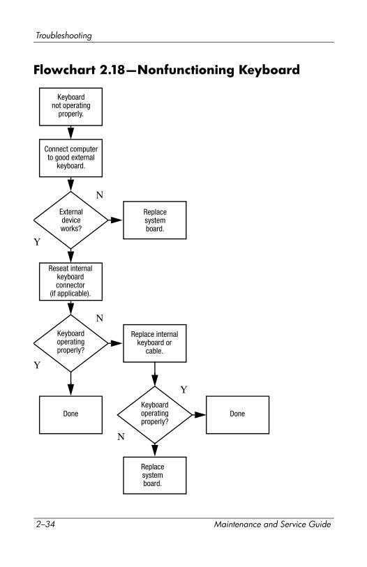
Flowchart 2.18—Nonfunctioning Keyboard
Y
N
Keyboardoperatingproperly?
Keyboardnot operating
properly.
Externaldeviceworks?
Replacesystemboard.
Replacesystemboard.
Connect computerto good external
keyboard.
Reseat internal keyboardconnector
(if applicable).
Replace internalkeyboard or
cable.
Y
N
Y
N
Done DoneKeyboardoperatingproperly?
2–34 Maintenance and Service Guide

Troubleshooting
Flowchart 2.19—Nonfunctioning Pointing Device
Y
N
Pointing devicenot operating
properly.
Externaldeviceworks?
Replacesystemboard.
Replacesystemboard.
Connect computerto good externalpointing device.
Reseat internalpointing device
connector (if applicable).
Replace internalpointing device
or cable.
Y
N
Y
N
Done Done
Pointing deviceoperatingproperly?
Pointing deviceoperatingproperly?
Maintenance and Service Guide 2–35
Troubleshooting
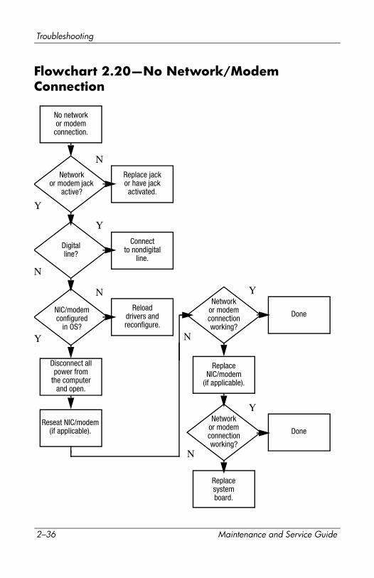
Flowchart 2.20—No Network/Modem Connection
Y
Disconnect allpower from
the computerand open.
No networkor modem
connection.
N
Done
Digitalline?
Networkor modem jack
active?
Replace jack or have jack activated.
Connectto nondigital
line.
NIC/modem configured
in OS?
Reloaddrivers and reconfigure.
Reseat NIC/modem(if applicable).
ReplaceNIC/modem
(if applicable).
Replacesystemboard.
Done
N
N
N
N
Y
Y
Y
Y
Networkor modem connection working?
Networkor modem connection working?
2–36 Maintenance and Service Guide
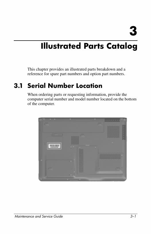
3Illustrated Parts Catalog
This chapter provides an illustrated parts breakdown and a reference for spare part numbers and option part numbers.
3.1 Serial Number LocationWhen ordering parts or requesting information, provide the computer serial number and model number located on the bottom of the computer.
Maintenance and Service Guide 3–1
Illustrated Parts Catalog
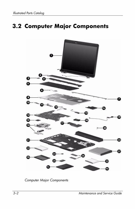
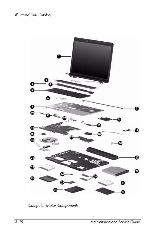
3.2 Computer Major Components
Computer Major Components
3–2 Maintenance and Service Guide
Illustrated Parts Catalog
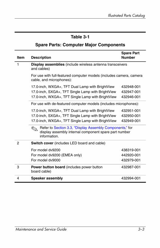
Table 3-1
Spare Parts: Computer Major Components
Item DescriptionSpare Part Number
1 Display assemblies (include wireless antenna transceivers and cables)
For use with full-featured computer models (includes camera, camera cable, and microphones):
17.0-inch, WXGA+, TFT Dual Lamp with BrightView17.0-inch, SXGA+, TFT Single Lamp with BrightView17.0-inch, WXGA+, TFT Single Lamp with BrightView
432948-001432947-001432946-001
For use with de-featured computer models (includes microphones):
17.0-inch, WXGA+, TFT Dual Lamp with BrightView17.0-inch, SXGA+, TFT Single Lamp with BrightView17.0-inch, WXGA+, TFT Single Lamp with BrightView
432951-001432950-001432949-001
✎ Refer to Section 3.3, “Display Assembly Components,” for display assembly internal component spare part number information.
2 Switch cover (includes LED board and cable)
For model dv9200For model dv9200 (EMEA only)For model dv9000
438319-001442920-001432979-001
3 Power button board (includes power button board cable)
432987-001
4 Speaker assembly 432994-001
Maintenance and Service Guide 3–3

Illustrated Parts Catalog
Computer Major Components
3–4 Maintenance and Service Guide
Illustrated Parts Catalog
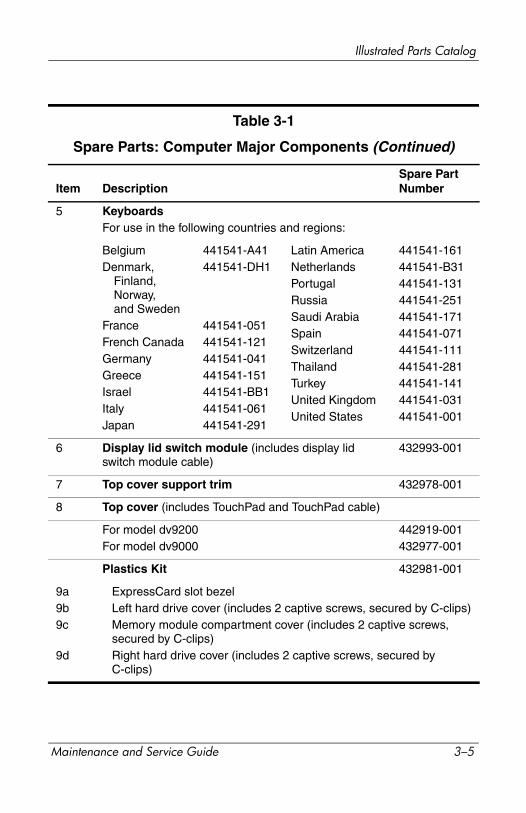
Table 3-1
Spare Parts: Computer Major Components (Continued)
Item DescriptionSpare Part Number
5 KeyboardsFor use in the following countries and regions:
BelgiumDenmark,
Finland, Norway, and Sweden
FranceFrench CanadaGermanyGreeceIsraelItalyJapan
441541-A41441541-DH1
441541-051441541-121441541-041441541-151441541-BB1441541-061441541-291
Latin AmericaNetherlandsPortugalRussiaSaudi ArabiaSpainSwitzerlandThailandTurkeyUnited KingdomUnited States
441541-161441541-B31441541-131441541-251441541-171441541-071441541-111441541-281441541-141441541-031441541-001
6 Display lid switch module (includes display lid switch module cable)
432993-001
7 Top cover support trim 432978-001
8 Top cover (includes TouchPad and TouchPad cable)
For model dv9200For model dv9000
442919-001432977-001
Plastics Kit 432981-001
9a9b9c
9d
ExpressCard slot bezelLeft hard drive cover (includes 2 captive screws, secured by C-clips)Memory module compartment cover (includes 2 captive screws, secured by C-clips)Right hard drive cover (includes 2 captive screws, secured by C-clips)
Maintenance and Service Guide 3–5

Illustrated Parts Catalog
Computer Major Components
3–6 Maintenance and Service Guide
Illustrated Parts Catalog
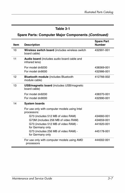
Table 3-1
Spare Parts: Computer Major Components (Continued)
Item DescriptionSpare Part Number
10 Wireless switch board (includes wireless switch board cable)
432991-001
11 Audio board (includes audio board cable and infrared lens)
For model dv9200For model dv9000
438369-001432986-001
12 Bluetooth module (includes Bluetooth module cable)
412766-002
13 USB/magnetic board (includes USB/magnetic board cable)
For model dv9200For model dv9000
438370-001432990-001
14 System boards
For use only with computer models using Intel processors:
G73 (includes 512 MB of video RAM)G73M (includes 256 MB of video RAM)G73 (includes 512 MB of video RAM) - for Germany onlyG73 (includes 256 MB of video RAM) - for Germany only
434660-001434659-001441620-001
445178-001
For use only with computer models using AMD processors
444002-001
Maintenance and Service Guide 3–7

Illustrated Parts Catalog
Computer Major Components
3–8 Maintenance and Service Guide
Illustrated Parts Catalog
Table 3-1Spare Parts: Computer Major Components (Continued)
Item DescriptionSpare Part Number
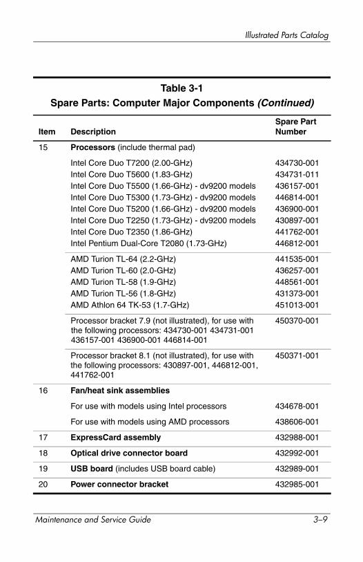
15 Processors (include thermal pad)
Intel Core Duo T7200 (2.00-GHz)Intel Core Duo T5600 (1.83-GHz)Intel Core Duo T5500 (1.66-GHz) - dv9200 modelsIntel Core Duo T5300 (1.73-GHz) - dv9200 modelsIntel Core Duo T5200 (1.66-GHz) - dv9200 modelsIntel Core Duo T2250 (1.73-GHz) - dv9200 modelsIntel Core Duo T2350 (1.86-GHz)Intel Pentium Dual-Core T2080 (1.73-GHz)
434730-001434731-011436157-001446814-001436900-001430897-001441762-001446812-001
AMD Turion TL-64 (2.2-GHz)AMD Turion TL-60 (2.0-GHz)AMD Turion TL-58 (1.9-GHz)AMD Turion TL-56 (1.8-GHz)AMD Athlon 64 TK-53 (1.7-GHz)
441535-001436257-001448561-001431373-001451013-001
Processor bracket 7.9 (not illustrated), for use with the following processors: 434730-001 434731-001 436157-001 436900-001 446814-001
450370-001
Processor bracket 8.1 (not illustrated), for use with the following processors: 430897-001, 446812-001, 441762-001
450371-001
16 Fan/heat sink assemblies
For use with models using Intel processors 434678-001
For use with models using AMD processors 438606-001
17 ExpressCard assembly 432988-001
18 Optical drive connector board 432992-001
19 USB board (includes USB board cable) 432989-001
20 Power connector bracket 432985-001
Maintenance and Service Guide 3–9

Illustrated Parts Catalog
Computer Major Components
3–10 Maintenance and Service Guide
Illustrated Parts Catalog
Table 3-1
Spare Parts: Computer Major Components (Continued)
Item DescriptionSpare Part Number
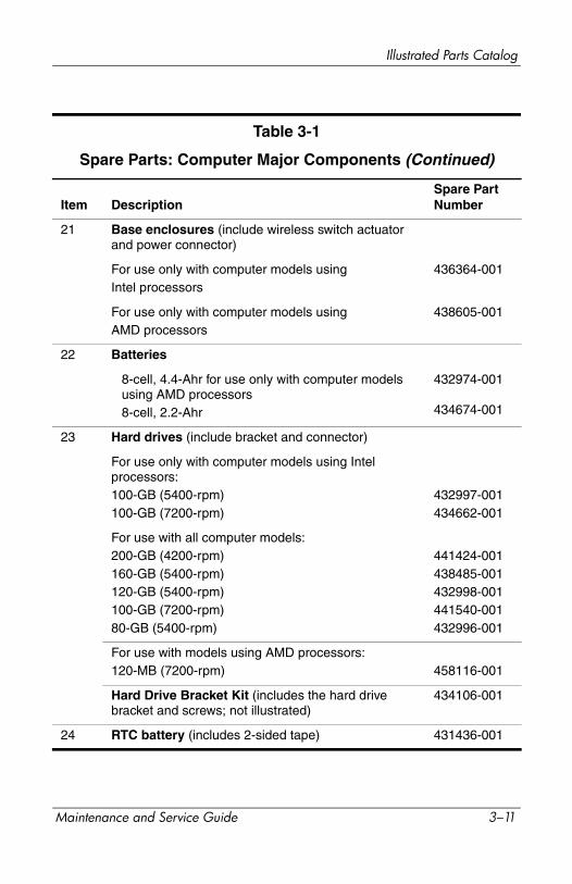
21 Base enclosures (include wireless switch actuator and power connector)
For use only with computer models usingIntel processors
436364-001
For use only with computer models usingAMD processors
438605-001
22 Batteries
8-cell, 4.4-Ahr for use only with computer models using AMD processors8-cell, 2.2-Ahr
432974-001
434674-001
23 Hard drives (include bracket and connector)
For use only with computer models using Intel processors:100-GB (5400-rpm)100-GB (7200-rpm)
432997-001434662-001
For use with all computer models:200-GB (4200-rpm)160-GB (5400-rpm)120-GB (5400-rpm)100-GB (7200-rpm)80-GB (5400-rpm)
441424-001438485-001432998-001441540-001432996-001
For use with models using AMD processors:120-MB (7200-rpm) 458116-001
Hard Drive Bracket Kit (includes the hard drive bracket and screws; not illustrated)
434106-001
24 RTC battery (includes 2-sided tape) 431436-001
Maintenance and Service Guide 3–11

Illustrated Parts Catalog
Computer Major Components
3–12 Maintenance and Service Guide

Illustrated Parts Catalog
Table 3-1
Spare Parts: Computer Major Components (Continued)
Item DescriptionSpare Part Number
25 Mini Card modules
802.11a/b/g WLAN Mini Card module for use in the countries or regions listed below. These countries and regions are categorized as most of the world1 (MOW1).
407674-001
Antigua & Barbuda
ArgentinaAustraliaBahamasBarbadosBrunei
CanadaChileDominican Republic
GuamGuatemalaHong Kong
PanamaIndiaIndonesiaMalaysiaMexicoNew Zealand
ParaguaySaudi ArabiaTaiwanThe United States
Vietnam
802.11a/b/g WLAN Mini Card module for use in the countries or regions listed below. These countries and regions are categorized as most of the world2 (MOW2).
407674-002
ArubaAustriaAzerbaijanBahrainBelgiumBermudaBulgariaCayman Islands
ColumbiaCroatiaCyprusThe Czech Republic
Denmark
EgyptEl SalvadorEstoniaFinlandFranceGeorgiaGermanyGreeceHungaryIcelandIrelandItalyLatviaLebanon
The PhilippinesPolandPortugalRomaniaRussiaSerbia and Montenegro
SingaporeSlovakiaLiechtensteinLithuaniaLuxembourgMaltaMonaco
The Netherlands
NorwayOmanSloveniaSouth AfricaSpainSri LankaSwedenSwitzerlandTurkeyThe UnitedKingdomUzbekistan
Maintenance and Service Guide 3–13

Illustrated Parts Catalog
Computer Major Components
3–14 Maintenance and Service Guide
Illustrated Parts Catalog
Table 3-1
Spare Parts: Computer Major Components (Continued)
Item DescriptionSpare Part Number
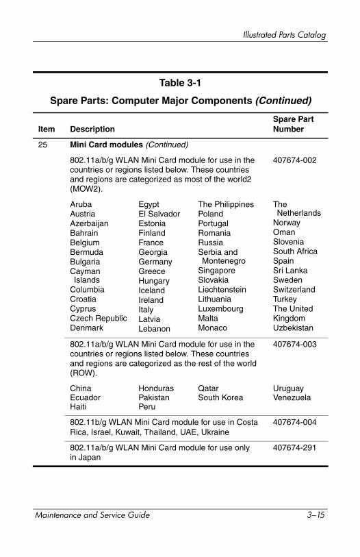
25 Mini Card modules (Continued)
802.11a/b/g WLAN Mini Card module for use in the countries or regions listed below. These countries and regions are categorized as most of the world2 (MOW2).
407674-002
ArubaAustriaAzerbaijanBahrainBelgiumBermudaBulgariaCayman Islands
ColumbiaCroatiaCyprusCzech RepublicDenmark
EgyptEl SalvadorEstoniaFinlandFranceGeorgiaGermanyGreeceHungaryIcelandIrelandItalyLatviaLebanon
The PhilippinesPolandPortugalRomaniaRussiaSerbia and Montenegro
SingaporeSlovakiaLiechtensteinLithuaniaLuxembourgMaltaMonaco
The Netherlands
NorwayOmanSloveniaSouth AfricaSpainSri LankaSwedenSwitzerlandTurkeyThe UnitedKingdomUzbekistan
802.11a/b/g WLAN Mini Card module for use in the countries or regions listed below. These countries and regions are categorized as the rest of the world (ROW).
407674-003
ChinaEcuadorHaiti
HondurasPakistanPeru
QatarSouth Korea
UruguayVenezuela
802.11b/g WLAN Mini Card module for use in Costa Rica, Israel, Kuwait, Thailand, UAE, Ukraine
407674-004
802.11a/b/g WLAN Mini Card module for use only in Japan
407674-291
Maintenance and Service Guide 3–15

Illustrated Parts Catalog
Computer Major Components
3–16 Maintenance and Service Guide
Illustrated Parts Catalog
Table 3-1
Spare Parts: Computer Major Components (Continued)
Item DescriptionSpare Part Number
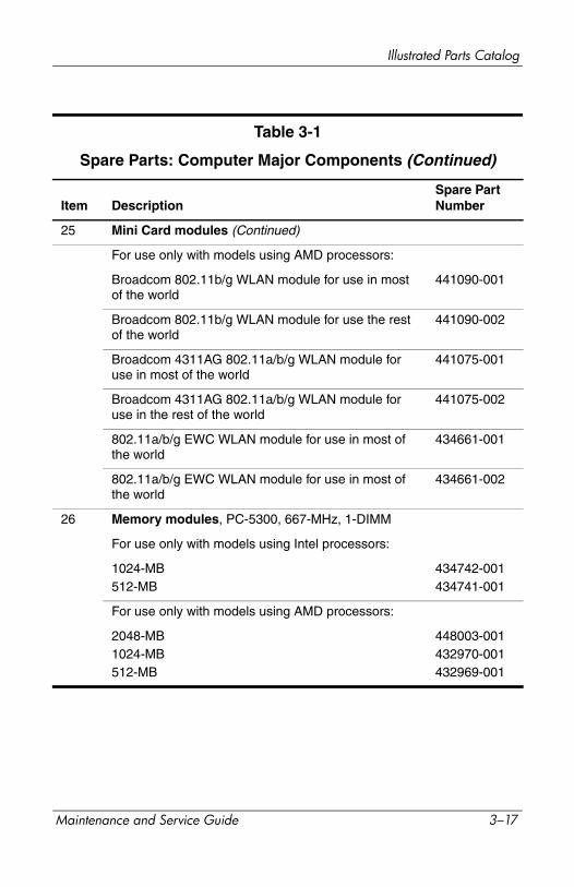
25 Mini Card modules (Continued)
For use only with models using AMD processors:
Broadcom 802.11b/g WLAN module for use in most of the world
441090-001
Broadcom 802.11b/g WLAN module for use the rest of the world
441090-002
Broadcom 4311AG 802.11a/b/g WLAN module for use in most of the world
441075-001
Broadcom 4311AG 802.11a/b/g WLAN module for use in the rest of the world
441075-002
802.11a/b/g EWC WLAN module for use in most of the world
434661-001
802.11a/b/g EWC WLAN module for use in most of the world
434661-002
26 Memory modules, PC-5300, 667-MHz, 1-DIMM
For use only with models using Intel processors:
1024-MB512-MB
434742-001434741-001
For use only with models using AMD processors:
2048-MB1024-MB512-MB
448003-001432970-001432969-001
Maintenance and Service Guide 3–17
Illustrated Parts Catalog
Computer Major Components
3–18 Maintenance and Service Guide

Illustrated Parts Catalog
Table 3-1
Spare Parts: Computer Major Components (Continued)
Item DescriptionSpare Part Number
27 Optical drives (include bezel)
DVD±RW/R and CD-RW Double-Layer Combo Drive with LightScribeDVD±RW/R and CD-RW Double-Layer Combo DriveDVD/CD-RW Combo Drive
432973-001
432972-001
434673-001
Cable Kit (not illustrated), includes: 434677-001
Audio board cableBluetooth module cableDisplay lid switch module cableUSB board cableUSB/magnetic board cable
Rubber Kit (not illustrated), includes: 432982-001
Rubber feet2nd hard drive doorRubber hingeDisplay panel bumpers
Maintenance and Service Guide 3–19
Illustrated Parts Catalog
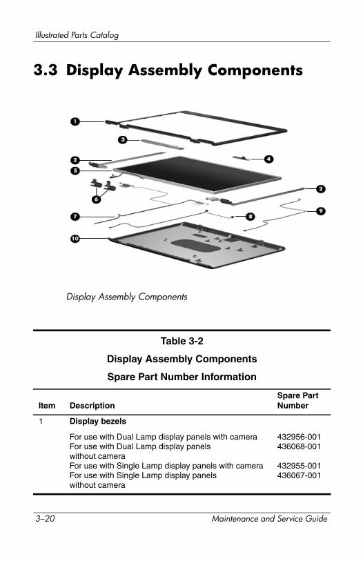
3.3 Display Assembly Components
Display Assembly Components
Table 3-2
Display Assembly Components
Spare Part Number Information
Item DescriptionSpare Part Number
1 Display bezels
For use with Dual Lamp display panels with cameraFor use with Dual Lamp display panelswithout cameraFor use with Single Lamp display panels with cameraFor use with Single Lamp display panelswithout camera
432956-001436068-001
432955-001436067-001
3–20 Maintenance and Service Guide
Illustrated Parts Catalog
2 Display Hinge Kit (includes left and right display hinges)
For use with Dual Lamp display panelsFor use with Single Lamp display panels
432964-001432963-001
3 Display inverters
For use with Dual Lamp display panelsFor use with Single Lamp display panels
432959-001431391-001
4 Camera module 432960-001
5 Display panels
17.0-inch, WXGA+, TFT Dual Lamp display panel with BrightView17.0-inch, SXGA+, TFT Single Lamp display panel with BrightView17.0-inch, WXGA+, TFT Single Lamp display panel with BrightView
432954-001
432953-001
432952-001
6 Display hinge covers 432965-001
7 Wireless antenna transceivers and cables 432966-001
8 Microphones 432961-001
9 Display Cable Kit (includes camera cable) 432962-001
10 Display enclosures
For use with Dual Lamp display panelsFor use with Single Lamp display panel
432958-001432957-001
Display Screw Kit (includes screws and rubber screw covers, not illustrated)
432967-001
Table 3-2
Display Assembly Components
Spare Part Number Information (Continued)
Item DescriptionSpare Part Number
Maintenance and Service Guide 3–21

Illustrated Parts Catalog
3.4 Mass Storage Devices
Mass Storage Devices
Table 3-3
Mass Storage Devices
Spare Part Number Information
Item DescriptionSpare Part Number
1 Hard drives (include bracket and connector)
For use only with computer models using Intel processors:
100-GB (7200-rpm)100-GB (5400-rpm)
434662-001432997-001
3–22 Maintenance and Service Guide
Illustrated Parts Catalog
For use with all computer models
200-GB (4200-rpm)160-GB (5400-rpm)120-GB (5400-rpm)100-GB (7200-rpm)80-GB (5400-rpm)
441424-001438485-001432998-001441540-001432996-001
For use with computer models using AMD processors:
120-MB (7200-rpm) 458116-001
1 Hard drives (Continued)
Hard drive Bracket Kit (not illustrated) 434106-001
Hard drive bracket rails (APD only) (not illustrated) 437385-001
Hard drive screws (APD only) (not illustrated) 437386-001
Hard drive connector (APD only) (not illustrated) 437387-001
2 Optical drives
DVD±RW/R and CD-RW Double-Layer Combo Drive with LightScribeDVD±RW/R and CD-RW Double-Layer Combo DriveDVD/CD-RW Combo Drive
432973-001
432972-001434673-001
Table 3-3
Mass Storage Devices
Spare Part Number Information (Continued)
Item DescriptionSpare Part Number
Maintenance and Service Guide 3–23
Illustrated Parts Catalog
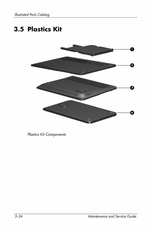
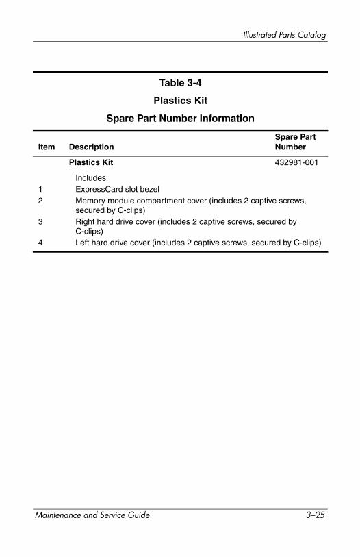
3.5 Plastics Kit
Plastics Kit Components
3–24 Maintenance and Service Guide
Illustrated Parts Catalog
Table 3-4
Plastics Kit
Spare Part Number Information
Item DescriptionSpare Part Number
Plastics Kit 432981-001
12
3
4
Includes:ExpressCard slot bezelMemory module compartment cover (includes 2 captive screws, secured by C-clips)Right hard drive cover (includes 2 captive screws, secured by C-clips)Left hard drive cover (includes 2 captive screws, secured by C-clips)
Maintenance and Service Guide 3–25
Illustrated Parts Catalog
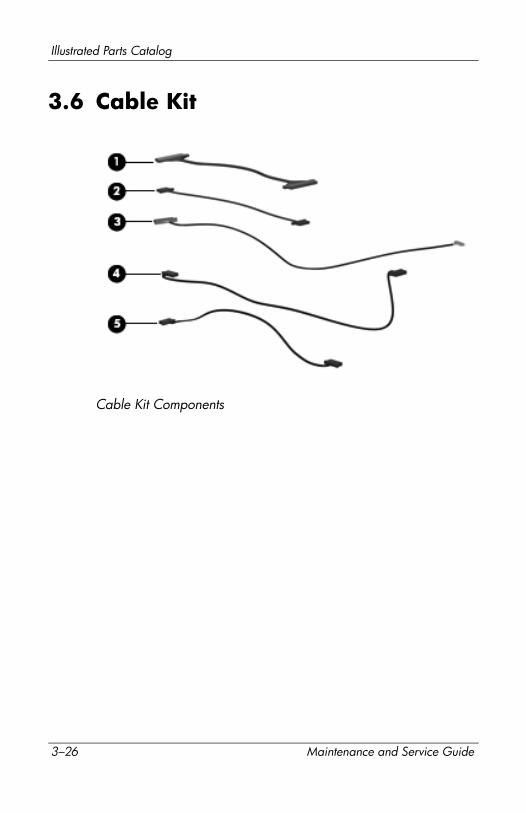
3.6 Cable Kit
Cable Kit Components
3–26 Maintenance and Service Guide

Illustrated Parts Catalog
Table 3-5
Cable Kit
Spare Part Number Information
Item DescriptionSpare Part Number
Cable Kit 434677-001
12345
Includes:Audio board cableDisplay lid switch module cableBluetooth module cableUSB board cableUSB/magnetic board cable
Maintenance and Service Guide 3–27

Illustrated Parts Catalog
3.7 Miscellaneous
Table 3-6
Spare Parts: Miscellaneous
DescriptionSpare Part Number
AC adapters
HP 90-W PFC AC adapterHP 90-W non-PFC AC adapter
432309-001432310-001
Composite S-Video and audio input cable 407939-001
Analog TV tuner 407941-001
Composite S-Video and audio input cable 407939-001
DVB-T TV tuner 412175-001
DVB-T TV tuner antenna 412176-001
DVB-T TV tuner antenna and antenna adapter 412176-002
Ear bud headset 371693-001
Backpack 405527-001
HP Remote Control 407313-001
Logo Kit 432984-001
RF input adapter cable 407940-001
USB digital drive 364727-001
USB travel mouse 435836-001
Optical wired mouse 436238-001
Remote control, ExpressCard (EMEA) 439254-001
Infrared emitter 439129-001
HP Remote Control 435743-001
Remote control, ExpressCard 439128-001
3–28 Maintenance and Service Guide
Illustrated Parts Catalog
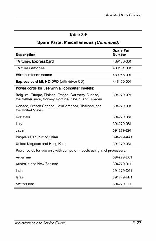
TV tuner, ExpressCard 439130-001
TV tuner antenna 439131-001
Wireless laser mouse 430958-001
Express card kit, HD-DVD (with driver CD) 445170-001
Power cords for use with all computer models:
Belgium, Europe, Finland, France, Germany, Greece, the Netherlands, Norway, Portugal, Spain, and Sweden
394279-021
Canada, French Canada, Latin America, Thailand, and the United States
394279-001
Denmark 394279-081
Italy 394279-061
Japan 394279-291
People’s Republic of China 394279-AA1
United Kingdom and Hong Kong 394279-031
Power cords for use only with computer models using Intel processors:
Argentina 394279-D01
Australia and New Zealand 394279-011
India 394279-D61
Israel 394279-BB1
Switzerland 394279-111
Table 3-6
Spare Parts: Miscellaneous (Continued)
DescriptionSpare Part Number
Maintenance and Service Guide 3–29

Illustrated Parts Catalog
Screw Kit (include the following screws; refer to Appendix A, “Screw Listing,” for more information on screw specifications and usage)
For use only with computer models using Intel processors 434676-001
For use only with computer models using AMD processors 432983-001
■ Phillips PM3.0×3.0 screw
■ Phillips PM2.5×11.0 screw
■ Phillips PM2.5×8.0 screw
■ Phillips PM2.5×7.0 screw
■ Phillips PM2.5×5.0 screw
■ Phillips PM2.5×4.0 screw
■ Phillips PM2.0×6.0 Screw■ Phillips PM2.0×5.0 captive screw
■ Phillips PM2.0×4.0 screw
■ Phillips PM2.0×3.0 screw
Table 3-6
Spare Parts: Miscellaneous (Continued)
DescriptionSpare Part Number
3–30 Maintenance and Service Guide
Illustrated Parts Catalog
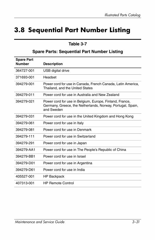
3.8 Sequential Part Number Listing
Table 3-7
Spare Parts: Sequential Part Number Listing
Spare Part Number Description
364727-001 USB digital drive
371693-001 Headset
394279-001 Power cord for use in Canada, French Canada, Latin America, Thailand, and the United States
394279-011 Power cord for use in Australia and New Zealand
394279-021 Power cord for use in Belgium, Europe, Finland, France, Germany, Greece, the Netherlands, Norway, Portugal, Spain, and Sweden
394279-031 Power cord for use in the United Kingdom and Hong Kong
394279-061 Power cord for use in Italy
394279-081 Power cord for use in Denmark
394279-111 Power cord for use in Switzerland
394279-291 Power cord for use in Japan
394279-AA1 Power cord for use in The People’s Republic of China
394279-BB1 Power cord for use in Israel
394279-D01 Power cord for use in Argentina
394279-D61 Power cord for use in India
405527-001 HP Backpack
407313-001 HP Remote Control
Maintenance and Service Guide 3–31
Illustrated Parts Catalog
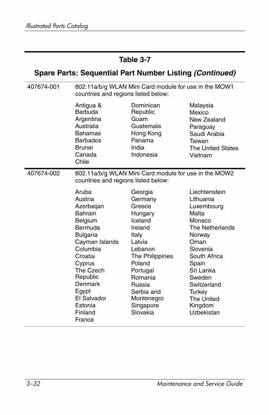
407674-001 802.11a/b/g WLAN Mini Card module for use in the MOW1 countries and regions listed below:
Antigua & BarbudaArgentinaAustraliaBahamasBarbadosBruneiCanadaChile
Dominican RepublicGuamGuatemalaHong KongPanamaIndiaIndonesia
MalaysiaMexicoNew ZealandParaguaySaudi ArabiaTaiwanThe United StatesVietnam
407674-002 802.11a/b/g WLAN Mini Card module for use in the MOW2 countries and regions listed below:
ArubaAustriaAzerbaijanBahrainBelgiumBermudaBulgariaCayman IslandsColumbiaCroatiaCyprusThe Czech RepublicDenmarkEgyptEl SalvadorEstoniaFinlandFrance
GeorgiaGermanyGreeceHungaryIcelandIrelandItalyLatviaLebanonThe PhilippinesPolandPortugalRomaniaRussiaSerbia and MontenegroSingaporeSlovakia
LiechtensteinLithuaniaLuxembourgMaltaMonacoThe NetherlandsNorwayOmanSloveniaSouth AfricaSpainSri LankaSwedenSwitzerlandTurkeyThe United KingdomUzbekistan
Table 3-7
Spare Parts: Sequential Part Number Listing (Continued)
3–32 Maintenance and Service Guide
Illustrated Parts Catalog
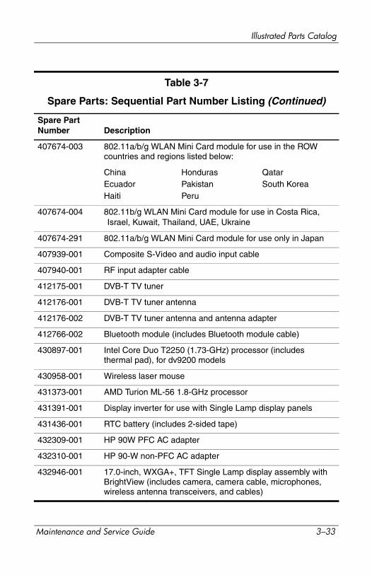
Spare Part Number Description
407674-003 802.11a/b/g WLAN Mini Card module for use in the ROW countries and regions listed below:
ChinaEcuadorHaiti
HondurasPakistanPeru
QatarSouth Korea
407674-004 802.11b/g WLAN Mini Card module for use in Costa Rica, Israel, Kuwait, Thailand, UAE, Ukraine
407674-291 802.11a/b/g WLAN Mini Card module for use only in Japan
407939-001 Composite S-Video and audio input cable
407940-001 RF input adapter cable
412175-001 DVB-T TV tuner
412176-001 DVB-T TV tuner antenna
412176-002 DVB-T TV tuner antenna and antenna adapter
412766-002 Bluetooth module (includes Bluetooth module cable)
430897-001 Intel Core Duo T2250 (1.73-GHz) processor (includes thermal pad), for dv9200 models
430958-001 Wireless laser mouse
431373-001 AMD Turion ML-56 1.8-GHz processor
431391-001 Display inverter for use with Single Lamp display panels
431436-001 RTC battery (includes 2-sided tape)
432309-001 HP 90W PFC AC adapter
432310-001 HP 90-W non-PFC AC adapter
432946-001 17.0-inch, WXGA+, TFT Single Lamp display assembly with BrightView (includes camera, camera cable, microphones, wireless antenna transceivers, and cables)
Table 3-7
Spare Parts: Sequential Part Number Listing (Continued)
Maintenance and Service Guide 3–33
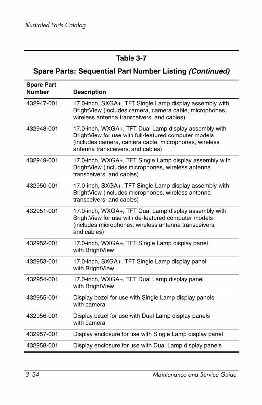
Illustrated Parts Catalog
Spare Part Number Description
432947-001 17.0-inch, SXGA+, TFT Single Lamp display assembly with BrightView (includes camera, camera cable, microphones, wireless antenna transceivers, and cables)
432948-001 17.0-inch, WXGA+, TFT Dual Lamp display assembly with BrightView for use with full-featured computer models (includes camera, camera cable, microphones, wireless antenna transceivers, and cables)
432949-001 17.0-inch, WXGA+, TFT Single Lamp display assembly with BrightView (includes microphones, wireless antenna transceivers, and cables)
432950-001 17.0-inch, SXGA+, TFT Single Lamp display assembly with BrightView (includes microphones, wireless antenna transceivers, and cables)
432951-001 17.0-inch, WXGA+, TFT Dual Lamp display assembly with BrightView for use with de-featured computer models (includes microphones, wireless antenna transceivers, and cables)
432952-001 17.0-inch, WXGA+, TFT Single Lamp display panel with BrightView
432953-001 17.0-inch, SXGA+, TFT Single Lamp display panel with BrightView
432954-001 17.0-inch, WXGA+, TFT Dual Lamp display panel with BrightView
432955-001 Display bezel for use with Single Lamp display panels with camera
432956-001 Display bezel for use with Dual Lamp display panels with camera
432957-001 Display enclosure for use with Single Lamp display panel
432958-001 Display enclosure for use with Dual Lamp display panels
Table 3-7
Spare Parts: Sequential Part Number Listing (Continued)
3–34 Maintenance and Service Guide
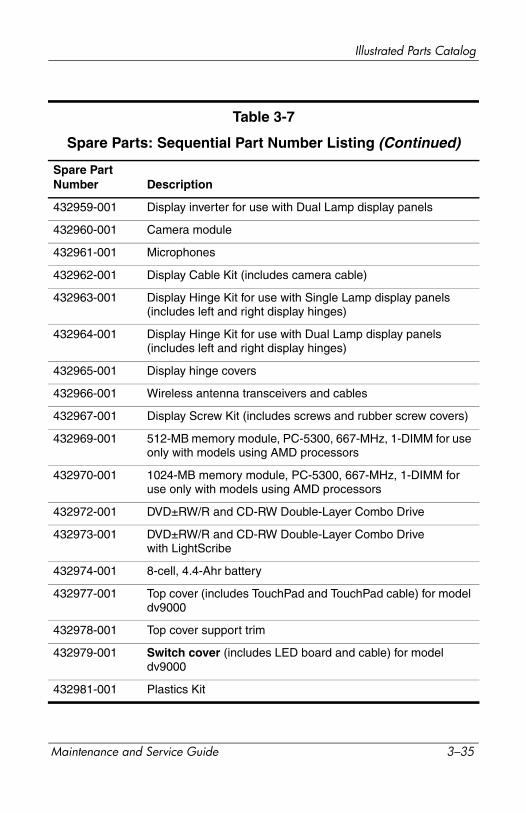
Illustrated Parts Catalog
Spare Part Number Description
432959-001 Display inverter for use with Dual Lamp display panels
432960-001 Camera module
432961-001 Microphones
432962-001 Display Cable Kit (includes camera cable)
432963-001 Display Hinge Kit for use with Single Lamp display panels (includes left and right display hinges)
432964-001 Display Hinge Kit for use with Dual Lamp display panels (includes left and right display hinges)
432965-001 Display hinge covers
432966-001 Wireless antenna transceivers and cables
432967-001 Display Screw Kit (includes screws and rubber screw covers)
432969-001 512-MB memory module, PC-5300, 667-MHz, 1-DIMM for use only with models using AMD processors
432970-001 1024-MB memory module, PC-5300, 667-MHz, 1-DIMM for use only with models using AMD processors
432972-001 DVD±RW/R and CD-RW Double-Layer Combo Drive
432973-001 DVD±RW/R and CD-RW Double-Layer Combo Drive with LightScribe
432974-001 8-cell, 4.4-Ahr battery
432977-001 Top cover (includes TouchPad and TouchPad cable) for model dv9000
432978-001 Top cover support trim
432979-001 Switch cover (includes LED board and cable) for model dv9000
432981-001 Plastics Kit
Table 3-7
Spare Parts: Sequential Part Number Listing (Continued)
Maintenance and Service Guide 3–35
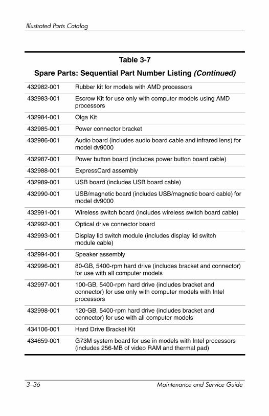
Illustrated Parts Catalog
432982-001 Rubber kit for models with AMD processors
432983-001 Escrow Kit for use only with computer models using AMD processors
432984-001 Olga Kit
432985-001 Power connector bracket
432986-001 Audio board (includes audio board cable and infrared lens) for model dv9000
432987-001 Power button board (includes power button board cable)
432988-001 ExpressCard assembly
432989-001 USB board (includes USB board cable)
432990-001 USB/magnetic board (includes USB/magnetic board cable) for model dv9000
432991-001 Wireless switch board (includes wireless switch board cable)
432992-001 Optical drive connector board
432993-001 Display lid switch module (includes display lid switch module cable)
432994-001 Speaker assembly
432996-001 80-GB, 5400-rpm hard drive (includes bracket and connector) for use with all computer models
432997-001 100-GB, 5400-rpm hard drive (includes bracket and connector) for use only with computer models with Intel processors
432998-001 120-GB, 5400-rpm hard drive (includes bracket and connector) for use with all computer models
434106-001 Hard Drive Bracket Kit
434659-001 G73M system board for use in models with Intel processors (includes 256-MB of video RAM and thermal pad)
Table 3-7
Spare Parts: Sequential Part Number Listing (Continued)
3–36 Maintenance and Service Guide

Illustrated Parts Catalog
Spare Part Number Description
434660-001 G73 system board for use in models with Intel processors (includes 512-MB of video RAM and thermal pad)
434661-001 802.11a/b/g EWC WLAN module for use in most of the world
434661-002 802.11a/b/g EWC WLAN module for use in the rest of the world
434662-001 100-GB, 7200-rpm hard drive (includes bracket and connector) for use only with computer models using Intel processors
434673-001 DVD/CD-RW Combo Drive
434674-001 8-cell, 2.2-Ahr battery
434676-001 Screw Kit for use only with computer models using Intel processors
434677-001 Cable Kit
434678-001 Fan/heat sink assembly for use in computer models with Intel processors (includes thermal pad)
434730-001 Intel Core Duo T7200 (2.0-GHz) processor (includes thermal pad)
434731-001 Intel Core Duo T5600 (1.8-GHz) processor (includes thermal pad)
434741-001 512-MB memory module, PC-5300, 667-MHz, 1-DIMM for use only with models using Intel processors
434742-001 1024-MB memory module, PC-5300, 667-MHz, 1-DIMM for use only with models using Intel processors
435743-001 HP Remote Control
435836-001 USB travel mouse
436067-001 Display bezel for use with Single Lamp display panelswithout camera
Table 3-7
Spare Parts: Sequential Part Number Listing (Continued)
Maintenance and Service Guide 3–37

Illustrated Parts Catalog
436068-001 Display bezel for use with Dual Lamp display panelswithout camera
436157-001 Intel Core Duo T5500 (1.66-GHz) processor (includes thermal pad), for use with dv9200 models
436238-001 Optical wired mouse
436257-001 AMD Turion ML-60 2.0-GHz processor
436364-001 Base enclosure (includes wireless switch actuator and power connector)
436900-001 Intel Core Duo T5200 (1.66-GHz) processor (includes thermal pad), for use with dv9200 models
437385-001 Hard drive bracket rails (APD only)
437386-001 Hard drive screws (APD only)
437387-001 Hard drive connector (APD only)
438319-001 Switch cover (includes LED board and LED board cable) for model dv9200
438369-001 Audio board (includes audio board cable and infrared lens) for model dv9200
438370-001 USB/magnetic board (includes USB/magnetic board cable) for model dv9200
438485-001 I160-GB (5400-rpm) hard drive for use with all computer models
438605-001 Base enclosure for use only with computer models using AMD processors (includes power connector)
438606-001 Fansink assembly for use only with computer models using AMD processors
439128-001 Remote control, ExpressCard
439129-001 Infrared emitter
439130-001 TV tuner, ExpressCard
Table 3-7
Spare Parts: Sequential Part Number Listing (Continued)
3–38 Maintenance and Service Guide
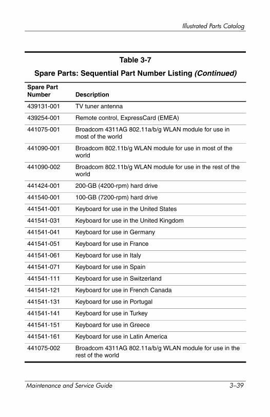
Illustrated Parts Catalog
Spare Part Number Description
439131-001 TV tuner antenna
439254-001 Remote control, ExpressCard (EMEA)
441075-001 Broadcom 4311AG 802.11a/b/g WLAN module for use in most of the world
441090-001 Broadcom 802.11b/g WLAN module for use in most of the world
441090-002 Broadcom 802.11b/g WLAN module for use in the rest of the world
441424-001 200-GB (4200-rpm) hard drive
441540-001 100-GB (7200-rpm) hard drive
441541-001 Keyboard for use in the United States
441541-031 Keyboard for use in the United Kingdom
441541-041 Keyboard for use in Germany
441541-051 Keyboard for use in France
441541-061 Keyboard for use in Italy
441541-071 Keyboard for use in Spain
441541-111 Keyboard for use in Switzerland
441541-121 Keyboard for use in French Canada
441541-131 Keyboard for use in Portugal
441541-141 Keyboard for use in Turkey
441541-151 Keyboard for use in Greece
441541-161 Keyboard for use in Latin America
441075-002 Broadcom 4311AG 802.11a/b/g WLAN module for use in the rest of the world
Table 3-7
Spare Parts: Sequential Part Number Listing (Continued)
Maintenance and Service Guide 3–39
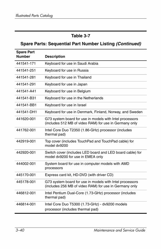
Illustrated Parts Catalog
Spare Part Number Description
441541-171 Keyboard for use in Saudi Arabia
441541-251 Keyboard for use in Russia
441541-281 Keyboard for use in Thailand
441541-291 Keyboard for use in Japan
441541-A41 Keyboard for use in Belgium
441541-B31 Keyboard for use in the Netherlands
441541-BB1 Keyboard for use in Israel
441541-DH1 Keyboard for use in Denmark, Finland, Norway, and Sweden
441620-001 G73 system board for use in models with Intel processors (includes 512 MB of video RAM) for use in Germany only
441762-001 Intel Core Duo T2350 (1.86-GHz) processor (includes thermal pad)
442919-001 Top cover (includes TouchPad and TouchPad cable) for model dv9200
442920-001 Switch cover (includes LED board and LED board cable) for model dv9200 for use in EMEA only
444002-001 System board for use in computer models with AMD processors
445170-001 Express card kit, HD-DVD (with driver CD)
445178-001 G73 system board for use in models with Intel processors (includes 256 MB of video RAM) for use in Germany only
446812-001 Intel Pentium Dual-Core (1.73-GHz) processor (includes thermal pad)
446814-001 Intel Core Duo T5300 (1.73-GHz) - dv9200 modelsprocessor (includes thermal pad)
Table 3-7
Spare Parts: Sequential Part Number Listing (Continued)
3–40 Maintenance and Service Guide
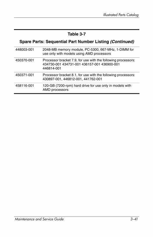
Illustrated Parts Catalog
448003-001 2048-MB memory module, PC-5300, 667-MHz, 1-DIMM for use only with models using AMD processors
450370-001 Processor bracket 7.9, for use with the following processors: 434730-001 434731-001 436157-001 436900-001 446814-001
450371-001 Processor bracket 8.1, for use with the following processors: 430897-001, 446812-001, 441762-001
458116-001 120-GB (7200-rpm) hard drive for use only in models with AMD processors
Table 3-7
Spare Parts: Sequential Part Number Listing (Continued)
Maintenance and Service Guide 3–41

Illustrated Parts Catalog
3–42 Maintenance and Service Guide
4Removal and Replacement
Preliminaries
This chapter provides essential information for proper and safe removal and replacement service.
4.1 Tools RequiredYou will need the following tools to complete the removal and replacement procedures:■ Magnetic screwdriver■ Phillips P0 and P1 screwdrivers■ Flat-bladed screwdriver
Maintenance and Service Guide 4–1
Removal and Replacement Preliminaries
4.2 Service ConsiderationsThe following sections include some of the considerations that you should keep in mind during disassembly and assembly procedures.
✎ As you remove each subassembly from the computer, place the subassembly (and all accompanying screws) away from the work area to prevent damage.
Plastic Parts
Using excessive force during disassembly and reassembly can damage plastic parts. Use care when handling the plastic parts. Apply pressure only at the points designated in the maintenance instructions.
Cables and Connectors
ÄCAUTION: When servicing the computer, ensure that cables are placed in their proper locations during the reassembly process. Improper cable placement can damage the computer.
Cables must be handled with extreme care to avoid damage. Apply only the tension required to unseat or seat the cables during removal and insertion. Handle cables by the connector whenever possible. In all cases, avoid bending, twisting, or tearing cables. Ensure that cables are routed in such a way that they cannot be caught or snagged by parts being removed or replaced. Handle flex cables with extreme care; these cables tear easily.
4–2 Maintenance and Service Guide

Removal and Replacement Preliminaries
4.3 Preventing Damage to Removable DrivesRemovable drives are fragile components that must be handled with care. To prevent damage to the computer, damage to a removable drive, or loss of information, observe the following precautions:■ Before removing or inserting a hard drive, shut down the
computer. If you are unsure whether the computer is off or in hibernation, turn the computer on, and then shut it down through the operating system.
■ Before removing a diskette drive or optical drive, ensure that a diskette or disc is not in the drive and ensure that the optical drive tray is closed.
■ Before handling a drive, ensure that you are discharged of static electricity. While handling a drive, avoid touching the connector.
■ Handle drives on surfaces covered with at least one inch of shock-proof foam.
■ Avoid dropping drives from any height onto any surface.■ After removing a hard drive, CD-ROM drive, or a diskette
drive, place it in a static-proof bag.■ Avoid exposing a hard drive to products that have magnetic
fields, such as monitors or speakers.■ Avoid exposing a drive to temperature extremes or liquids.■ If a drive must be mailed, place the drive in a bubble pack
mailer or other suitable form of protective packaging and label the package, “FRAGILE: Handle With Care.”
Maintenance and Service Guide 4–3
Removal and Replacement Preliminaries
4.4 Preventing Electrostatic DamageMany electronic components are sensitive to electrostatic discharge (ESD). Circuitry design and structure determine the degree of sensitivity. Networks built into many integrated circuits provide some protection, but in many cases, the discharge contains enough power to alter device parameters or melt silicon junctions.
A sudden discharge of static electricity from a finger or other conductor can destroy static-sensitive devices or microcircuitry. Often the spark is neither felt nor heard, but damage occurs.
An electronic device exposed to electrostatic discharge might not be affected at all and can work perfectly throughout a normal cycle. Or the device might function normally for a while, then degrade in the internal layers, reducing its life expectancy.
4–4 Maintenance and Service Guide
Removal and Replacement Preliminaries
4.5 Packaging and Transporting PrecautionsUse the following grounding precautions when packaging and transporting equipment:■ To avoid hand contact, transport products in static-safe
containers, such as tubes, bags, or boxes.■ Protect all electrostatic-sensitive parts and assemblies with
conductive or approved containers or packaging.■ Keep electrostatic-sensitive parts in their containers until
the parts arrive at static-free workstations.■ Place items on a grounded surface before removing items
from their containers.■ Always be properly grounded when touching a sensitive
component or assembly.■ Store reusable electrostatic-sensitive parts from assemblies
in protective packaging or nonconductive foam.■ Use transporters and conveyors made of antistatic belts and
roller bushings. Ensure that mechanized equipment used for moving materials is wired to ground and that proper materials are selected to avoid static charging. When grounding is not possible, use an ionizer to dissipate electric charges.
Maintenance and Service Guide 4–5
Removal and Replacement Preliminaries
4.6 Workstation PrecautionsUse the following grounding precautions at workstations:■ Cover the workstation with approved static-shielding material
(refer to Table 4-2, “Static-Shielding Materials”).■ Use a wrist strap connected to a properly grounded work
surface and use properly grounded tools and equipment.■ Use conductive field service tools, such as cutters,
screwdrivers, and vacuums.■ When using fixtures that must directly contact dissipative
surfaces, only use fixtures made of static-safe materials.■ Keep the work area free of nonconductive materials, such
as ordinary plastic assembly aids and Styrofoam.■ Handle electrostatic-sensitive components, parts, and
assemblies by the case or PCM laminate. Handle these items only at static-free workstations.
■ Avoid contact with pins, leads, or circuitry.■ Turn off power and input signals before inserting or removing
connectors or test equipment.
4–6 Maintenance and Service Guide
Removal and Replacement Preliminaries
4.7 Grounding Equipment and MethodsGrounding equipment must include either a wrist strap or a foot strap at a grounded workstation.■ When seated, wear a wrist strap connected to a grounded
system. Wrist straps are flexible straps with a minimum of one megohm ±10% resistance in the ground cords. To provide proper ground, wear a strap snugly against the skin at all times. On grounded mats with banana-plug connectors, use alligator clips to connect a wrist strap.
■ When standing, use foot straps and a grounded floor mat. Foot straps (heel, toe, or boot straps) can be used at standing workstations and are compatible with most types of shoes or boots. On conductive floors or dissipative floor mats, use foot straps on both feet with a minimum of one megohm resistance between the operator and ground. To be effective, the conductive strips must be worn in contact with the skin.
Other grounding equipment recommended for use in preventing electrostatic damage includes■ Antistatic tape.■ Antistatic smocks, aprons, and sleeve protectors.■ Conductive bins and other assembly or soldering aids.■ Nonconductive foam.■ Conductive tabletop workstations with ground cords of
one megohm resistance.■ Static-dissipative tables or floor mats with hard ties to
the ground.■ Field service kits.■ Static awareness labels.■ Material-handling packages.■ Nonconductive plastic bags, tubes, or boxes.■ Metal tote boxes.■ Electrostatic voltage levels and protective materials.
Maintenance and Service Guide 4–7

Removal and Replacement Preliminaries
Table 4-1 shows how humidity affects the electrostatic voltage levels generated by different activities.
Table 4-2 lists the shielding protection provided by antistatic bags and floor mats.
Table 4-1
Typical Electrostatic Voltage Levels
Relative Humidity
Event 10% 40% 55%
Walking across carpet 35,000 V 15,000 V 7,500 V
Walking across vinyl floor 12,000 V 5,000 V 3,000 V
Motions of bench worker 6,000 V 800 V 400 V
Removing DIPS from plastic tube 2,000 V 700 V 400 V
Removing DIPS from vinyl tray 11,500 V 4,000 V 2,000 V
Removing DIPS from Styrofoam 14,500 V 5,000 V 3,500 V
Removing bubble pack from PCB 26,500 V 20,000 V 7,000 V
Packing PCBs in foam-lined box 21,000 V 11,000 V 5,000 V
✎ A product can be degraded by as little as 700 V.
Table 4-2
Static-Shielding Materials
Material Use Voltage Protection Level
Antistatic plastic Bags 1,500 V
Carbon-loaded plastic Floor mats 7,500 V
Metallized laminate Floor mats 5,000 V
4–8 Maintenance and Service Guide
5Removal and Replacement
Procedures
This chapter provides removal and replacement procedures.
There are as many as 109 screws, in 11 different sizes, that must be removed, replaced, or loosened when servicing the computer. Make special note of each screw size and location during removal and replacement.
Refer to Appendix A, “Screw Listing,” for detailed information on screw sizes, locations, and usage.
Maintenance and Service Guide 5–1
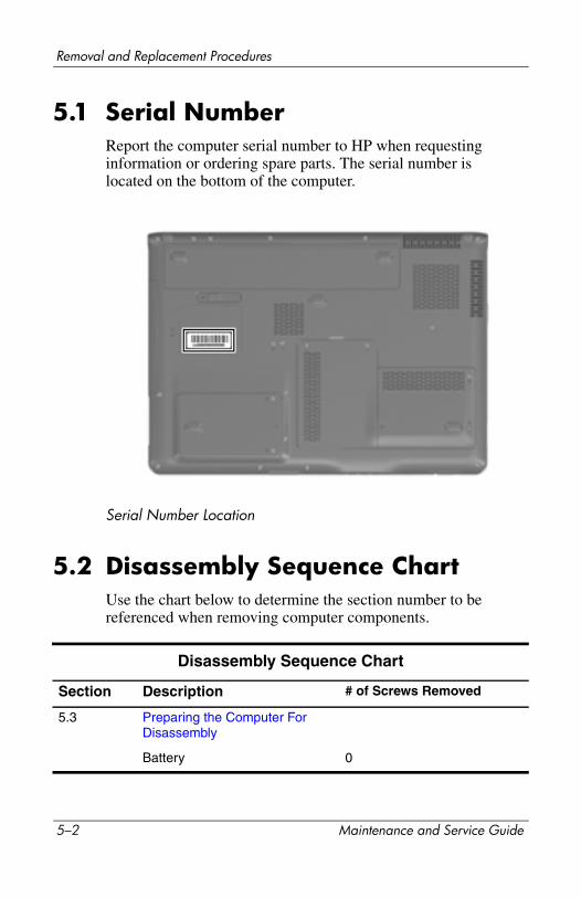
Removal and Replacement Procedures
5.1 Serial NumberReport the computer serial number to HP when requesting information or ordering spare parts. The serial number is located on the bottom of the computer.
Serial Number Location
5.2 Disassembly Sequence ChartUse the chart below to determine the section number to be referenced when removing computer components.
Disassembly Sequence Chart
Section Description # of Screws Removed
5.3 Preparing the Computer For Disassembly
Battery 0
5–2 Maintenance and Service Guide
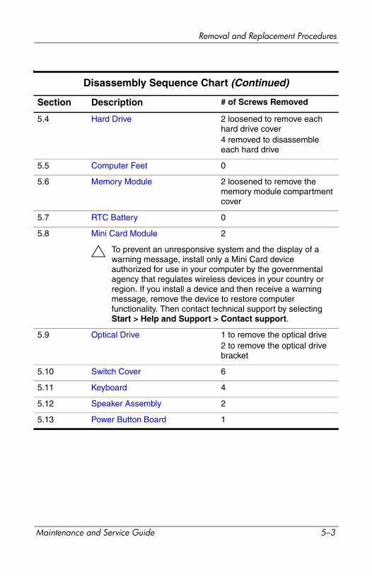
Removal and Replacement Procedures
Section Description # of Screws Removed
5.4 Hard Drive 2 loosened to remove each hard drive cover4 removed to disassemble each hard drive
5.5 Computer Feet 0
5.6 Memory Module 2 loosened to remove the memory module compartment cover
5.7 RTC Battery 0
5.8 Mini Card Module 2
Ä To prevent an unresponsive system and the display of a warning message, install only a Mini Card device authorized for use in your computer by the governmental agency that regulates wireless devices in your country or region. If you install a device and then receive a warning message, remove the device to restore computer functionality. Then contact technical support by selecting Start > Help and Support > Contact support.
5.9 Optical Drive 1 to remove the optical drive2 to remove the optical drive bracket
5.10 Switch Cover 6
5.11 Keyboard 4
5.12 Speaker Assembly 2
5.13 Power Button Board 1
Disassembly Sequence Chart (Continued)
Maintenance and Service Guide 5–3
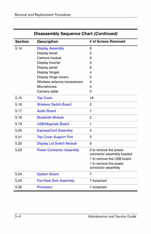
Removal and Replacement Procedures
Section Description # of Screws Removed
5.14 Display AssemblyDisplay bezelCamera moduleDisplay inverterDisplay panelDisplay hingesDisplay hinge coversWireless antenna transceiversMicrophonesCamera cable
6500640400
5.15 Top Cover 18
5.16 Wireless Switch Board 2
5.17 Audio Board 1
5.18 Bluetooth Module 2
5.19 USB/Magnetic Board 1
5.20 ExpressCard Assembly 4
5.21 Top Cover Support Trim 5
5.22 Display Lid Switch Module 0
5.23 Power Connector Assembly 2 to remove the power connector assembly bracket1 to remove the USB board1 to remove the power connector assembly
5.24 System Board 7
5.25 Fan/Heat Sink Assembly 7 loosened
5.26 Processor 1 loosened
Disassembly Sequence Chart (Continued)
5–4 Maintenance and Service Guide
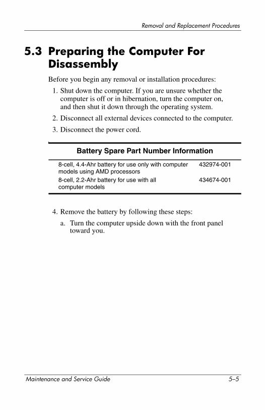
Removal and Replacement Procedures
5.3 Preparing the Computer For DisassemblyBefore you begin any removal or installation procedures:
1. Shut down the computer. If you are unsure whether the computer is off or in hibernation, turn the computer on, and then shut it down through the operating system.
2. Disconnect all external devices connected to the computer.
3. Disconnect the power cord.
4. Remove the battery by following these steps:
a. Turn the computer upside down with the front panel toward you.
Battery Spare Part Number Information
8-cell, 4.4-Ahr battery for use only with computer models using AMD processors8-cell, 2.2-Ahr battery for use with all computer models
432974-001
434674-001
Maintenance and Service Guide 5–5
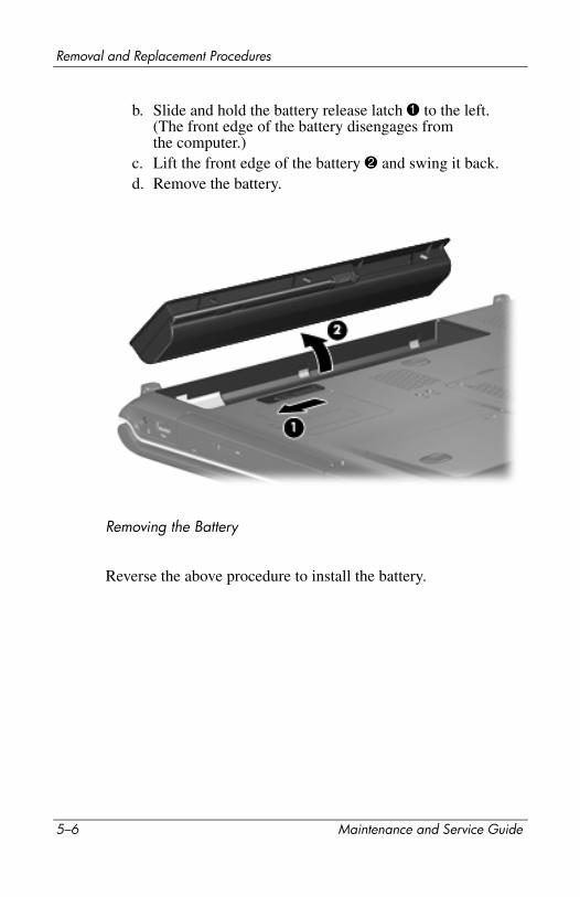
Removal and Replacement Procedures
b. Slide and hold the battery release latch 1 to the left. (The front edge of the battery disengages from the computer.)
c. Lift the front edge of the battery 2 and swing it back.d. Remove the battery.
Removing the Battery
Reverse the above procedure to install the battery.
5–6 Maintenance and Service Guide
Removal and Replacement Procedures
5.4 Hard Drive
Hard Drive Spare Part Number Information
Hard drives (include bracket and connector)
For use only with computer models using Intel processors:
100-GB (7200-rpm)100-GB (5400-rpm)
434662-001432997-001
For use with all computer models:
200-GB (4200-rpm)160-GB (5400-rpm)120-GB (5400-rpm)100-GB (7200-rpm)80-GB (5400-rpm)
441424-001438485-001432998-001441540-001432996-001
For use only with computer models using AMD processors:
120-GB (7200-rpm) 458116-001
Hard Drive Bracket Kit 434106-001
Maintenance and Service Guide 5–7
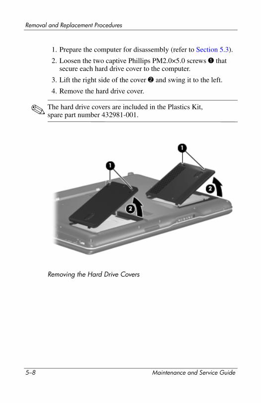
Removal and Replacement Procedures
1. Prepare the computer for disassembly (refer to Section 5.3).
2. Loosen the two captive Phillips PM2.0×5.0 screws 1 that secure each hard drive cover to the computer.
3. Lift the right side of the cover 2 and swing it to the left.
4. Remove the hard drive cover.
✎ The hard drive covers are included in the Plastics Kit, spare part number 432981-001.
Removing the Hard Drive Covers
5–8 Maintenance and Service Guide
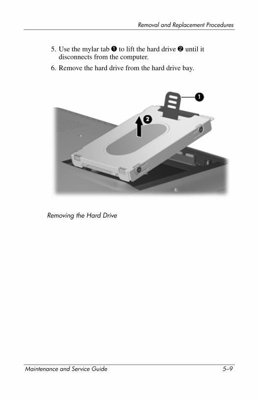
Removal and Replacement Procedures
5. Use the mylar tab 1 to lift the hard drive 2 until it disconnects from the computer.
6. Remove the hard drive from the hard drive bay.
Removing the Hard Drive
Maintenance and Service Guide 5–9
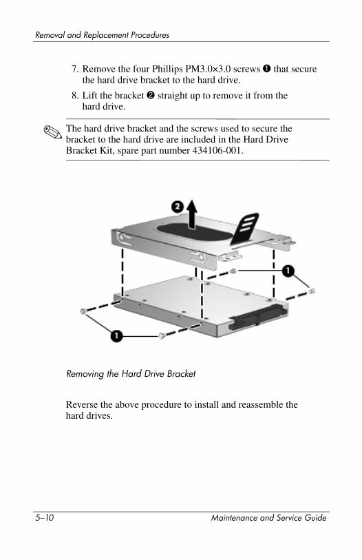
Removal and Replacement Procedures
7. Remove the four Phillips PM3.0×3.0 screws 1 that secure the hard drive bracket to the hard drive.
8. Lift the bracket 2 straight up to remove it from the hard drive.
✎ The hard drive bracket and the screws used to secure the bracket to the hard drive are included in the Hard Drive Bracket Kit, spare part number 434106-001.
Removing the Hard Drive Bracket
Reverse the above procedure to install and reassemble the hard drives.
5–10 Maintenance and Service Guide
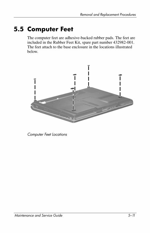
Removal and Replacement Procedures
5.5 Computer FeetThe computer feet are adhesive-backed rubber pads. The feet are included in the Rubber Feet Kit, spare part number 432982-001. The feet attach to the base enclosure in the locations illustrated below.
Computer Feet Locations
Maintenance and Service Guide 5–11

Removal and Replacement Procedures
5.6 Memory Module
1. Prepare the computer for disassembly (refer to Section 5.3).
Memory Module Spare Part Number Information
Memory modules, PC-5300, 667-MHz, 1-DIMM
For use only with models using Intel processors:
1024-MB512-MB
434742-001434741-001
For use only with models using AMD processors:
2048-MB1024-MB512-MB
448003-001432970-001432969-001
5–12 Maintenance and Service Guide

Removal and Replacement Procedures
2. Loosen the two captive Phillips PM2.0×5.0 screws 1 that secure the memory module compartment cover to the computer.
3. Lift the front of the memory module compartment cover 2, and then swing it back.
4. Remove the memory module compartment cover.
✎ The memory module compartment cover is included in the Plastics Kit, spare part number 432981-001.
Removing the Memory Module Compartment Cover
Maintenance and Service Guide 5–13
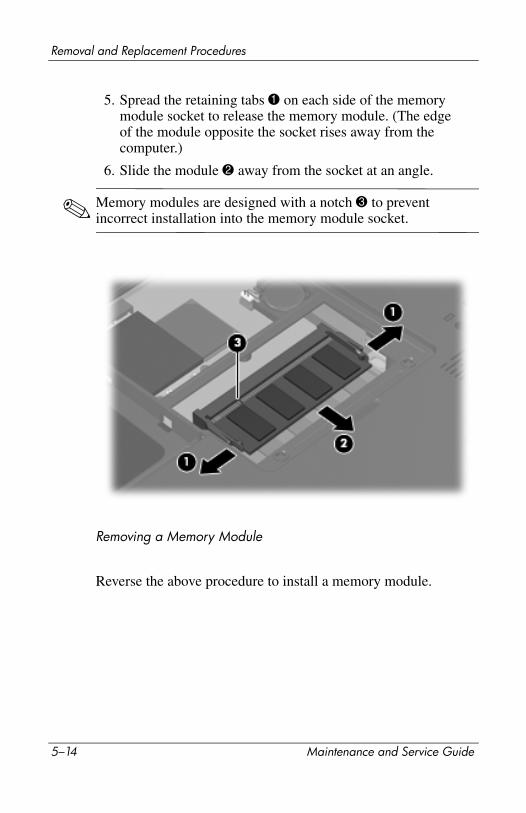
Removal and Replacement Procedures
5. Spread the retaining tabs 1 on each side of the memory module socket to release the memory module. (The edge of the module opposite the socket rises away from the computer.)
6. Slide the module 2 away from the socket at an angle.
✎ Memory modules are designed with a notch 3 to prevent incorrect installation into the memory module socket.
Removing a Memory Module
Reverse the above procedure to install a memory module.
5–14 Maintenance and Service Guide
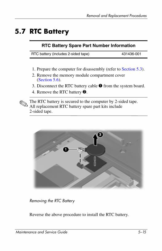
Removal and Replacement Procedures
5.7 RTC Battery
1. Prepare the computer for disassembly (refer to Section 5.3).2. Remove the memory module compartment cover
(Section 5.6).3. Disconnect the RTC battery cable 1 from the system board.4. Remove the RTC battery 2.
✎ The RTC battery is secured to the computer by 2-sided tape. All replacement RTC battery spare part kits include 2-sided tape.
Removing the RTC Battery
Reverse the above procedure to install the RTC battery.
RTC Battery Spare Part Number Information
RTC battery (includes 2-sided tape) 431436-001
Maintenance and Service Guide 5–15
Removal and Replacement Procedures
5.8 Mini Card Module
Mini Card Module
Spare Part Number Information
For use only with models using Intel processors:
802.11a/b/g WLAN Mini Card module for use in the MOW1 countries and regions listed below:
407674-001
Antigua & Barbuda
ArgentinaAustraliaBahamasBarbados
CanadaChileDominican Republic
GuamGuatemala
PanamaIndiaIndonesiaMalaysiaMexicoNew Zealand
ParaguaySaudi ArabiaTaiwanThe United StatesVietnam
802.11a/b/g WLAN Mini Card module for use in the MOW2 countries and regions listed below:
407674-002
ArubaAustriaAzerbaijanBahrainBelgiumBermudaBulgariaCayman IslandsColumbiaCroatiaCyprusThe Czech Republic
Denmark
EgyptEl SalvadorEstoniaFinlandFranceGeorgiaGermanyGreeceHungaryIcelandIrelandItalyLatviaLebanon
The PhilippinesPolandPortugalRomaniaRussiaSerbia andMontenegroSingaporeSlovakiaLiechtensteinLithuaniaLuxembourgMaltaMonaco
TheNetherlandsNorwayOmanSloveniaSouth AfricaSpainSri LankaSwedenSwitzerlandTurkeyThe UnitedKingdomUzbekistan
5–16 Maintenance and Service Guide

Removal and Replacement Procedures
1. Prepare the computer for disassembly (Section 5.3).
2. Remove the memory module compartment cover(Section 5.6).
802.11a/b/g WLAN Mini Card module for use in the ROW countries and regions listed below:
407674-003
ChinaEcuadorHaiti
HondurasPakistanPeru
QatarSouth Korea
UruguayVenezuela
802.11b/g WLAN Mini Card module for use in Costa Rica, Israel, Kuwait, Thailand, UAE, Ukraine.
407674-004
802.11a/b/g WLAN Mini Card module for use only in Japan 407674-291
For use only with models using AMD processors:
Broadcom 802.11b/g WLAN module for use in most of the world
441090-001
Broadcom 802.11b/g WLAN module for use the rest of the world
441090-002
Broadcom 4311AG 802.11a/b/g WLAN module for use in most of the world
441075-001
Broadcom 4311AG 802.11a/b/g WLAN module for use in the rest of the world
441075-002
802.11a/b/g EWC WLAN module for use in most of the world
434661-001
802.11a/b/g EWC WLAN module for use in most of the world
434661-002
Mini Card Module
Spare Part Number Information (Continued)
Maintenance and Service Guide 5–17
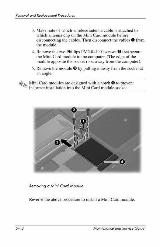
Removal and Replacement Procedures
3. Make note of which wireless antenna cable is attached to which antenna clip on the Mini Card module before disconnecting the cables. Then disconnect the cables 1 from the module.
4. Remove the two Phillips PM2.0×11.0 screws 2 that secure the Mini Card module to the computer. (The edge of the module opposite the socket rises away from the computer).
5. Remove the module 3 by pulling it away from the socket at an angle.
✎ Mini Card modules are designed with a notch 4 to prevent incorrect installation into the Mini Card module socket.
Removing a Mini Card Module
Reverse the above procedure to install a Mini Card module.
5–18 Maintenance and Service Guide

Removal and Replacement Procedures
5.9 Optical Drive
1. Prepare the computer for disassembly (Section 5.3).
2. Remove the Phillips PM2.5×8.0 screw 1 that secures the optical drive to the computer.
3. Insert a thin tool, such as a paper clip 2, into the media tray release hole. (The optical drive media tray releases from the optical drive.)
4. Use the media tray frame to slide the optical drive 3 out of the computer.
Optical Drive Spare Part Number Information
DVD±RW/R and CD-RW Double-Layer Combo Drive with LightScribeDVD±RW/R and CD-RW Double-Layer Combo DriveDVD/CD-RW Combo Drive
432973-001
432972-001434673-001
Maintenance and Service Guide 5–19
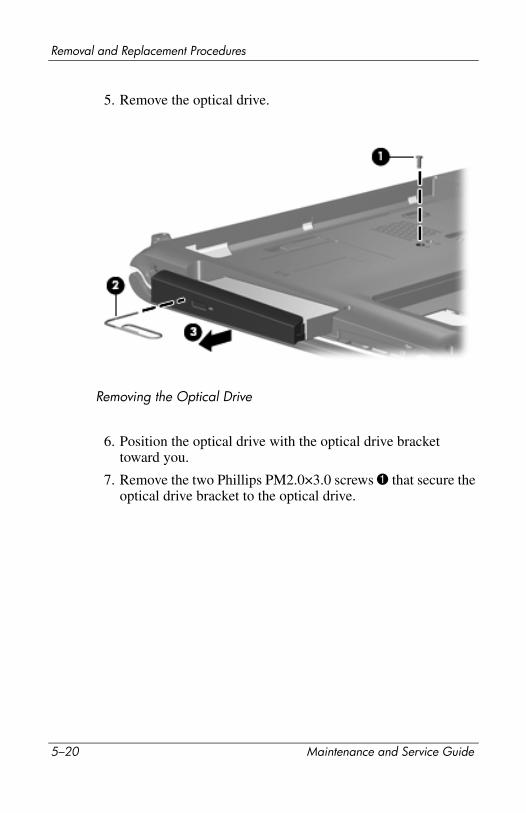
Removal and Replacement Procedures
5. Remove the optical drive.
Removing the Optical Drive
6. Position the optical drive with the optical drive bracket toward you.
7. Remove the two Phillips PM2.0×3.0 screws 1 that secure the optical drive bracket to the optical drive.
5–20 Maintenance and Service Guide
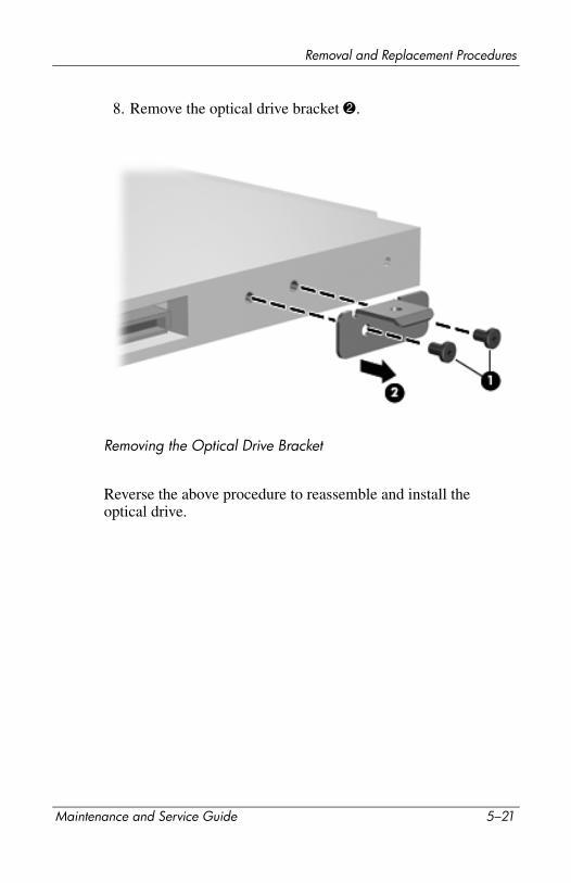
Removal and Replacement Procedures
8. Remove the optical drive bracket 2.
Removing the Optical Drive Bracket
Reverse the above procedure to reassemble and install the optical drive.
Maintenance and Service Guide 5–21

Removal and Replacement Procedures
5.10 Switch Cover
1. Prepare the computer for disassembly (Section 5.3).
2. Close the computer.
3. Turn the computer upside down with the front panel toward you.
4. Remove the six Phillips PM2.0×5.0 screws that secure the switch cover to the computer.
Switch Cover Spare Part Number Information
Switch cover (includes LED board and LED board cable), for model dv9000Switch cover (includes LED board and LED board cable), for model dv9200Switch cover (includes LED board and LED board cable), for model dv9200 for EMEA only
432979-001
438319-001
442920-001
5–22 Maintenance and Service Guide
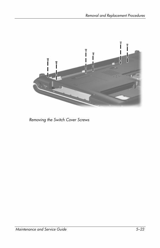
Removal and Replacement Procedures
Removing the Switch Cover Screws
Maintenance and Service Guide 5–23
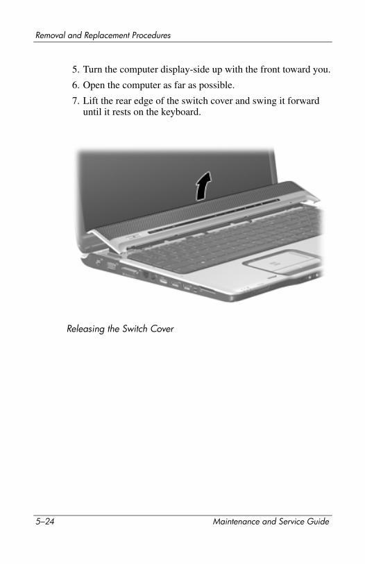
Removal and Replacement Procedures
5. Turn the computer display-side up with the front toward you.
6. Open the computer as far as possible.
7. Lift the rear edge of the switch cover and swing it forward until it rests on the keyboard.
Releasing the Switch Cover
5–24 Maintenance and Service Guide
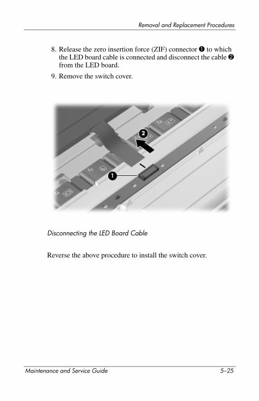
Removal and Replacement Procedures
8. Release the zero insertion force (ZIF) connector 1 to which the LED board cable is connected and disconnect the cable 2 from the LED board.
9. Remove the switch cover.
Disconnecting the LED Board Cable
Reverse the above procedure to install the switch cover.
Maintenance and Service Guide 5–25
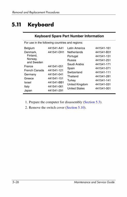
Removal and Replacement Procedures
5.11 Keyboard
1. Prepare the computer for disassembly (Section 5.3).
2. Remove the switch cover (Section 5.10).
Keyboard Spare Part Number Information
For use in the following countries and regions:
BelgiumDenmark,
Finland, Norway, and Sweden
FranceFrench CanadaGermanyGreeceIsraelItalyJapan
441541-A41441541-DH1
441541-051441541-121441541-041441541-151441541-BB1441541-061441541-291
Latin AmericaNetherlandsPortugalRussiaSaudi ArabiaSpainSwitzerlandThailandTurkeyUnited KingdomUnited States
441541-161441541-B31441541-131441541-251441541-171441541-071441541-111441541-281441541-141441541-031441541-001
5–26 Maintenance and Service Guide

Removal and Replacement Procedures
3. Remove the Phillips PM2.5×7.0 screw that secures the keyboard to the computer.
Removing the Keyboard Screw, Part 1
Maintenance and Service Guide 5–27
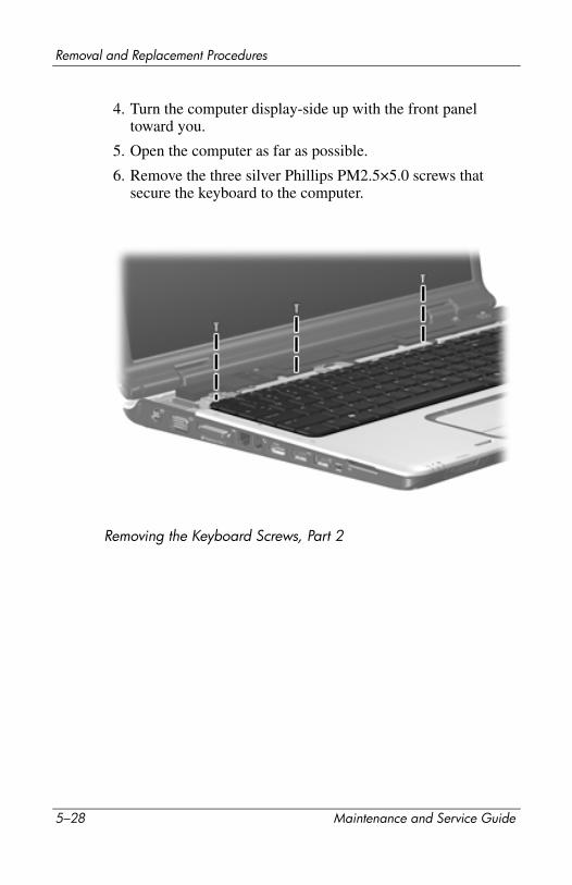
Removal and Replacement Procedures
4. Turn the computer display-side up with the front panel toward you.
5. Open the computer as far as possible.
6. Remove the three silver Phillips PM2.5×5.0 screws that secure the keyboard to the computer.
Removing the Keyboard Screws, Part 2
5–28 Maintenance and Service Guide
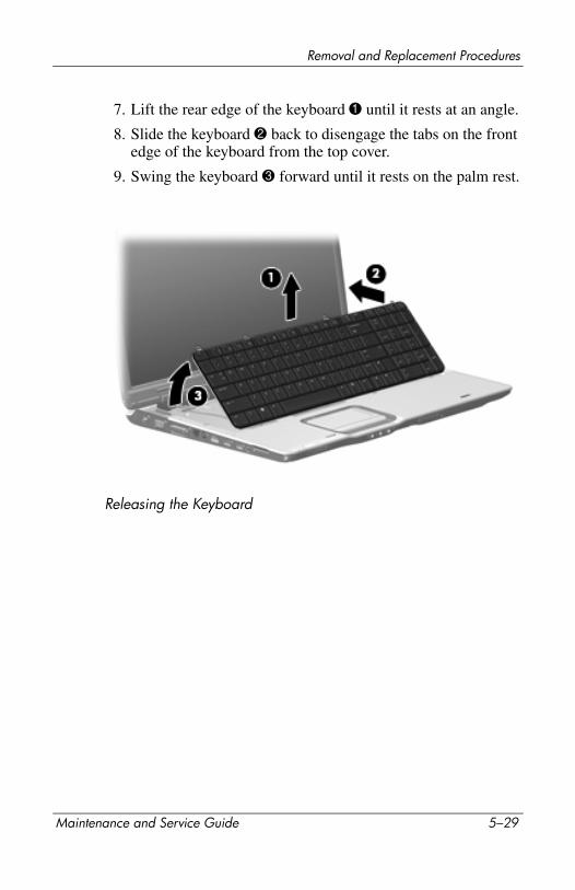
Removal and Replacement Procedures
7. Lift the rear edge of the keyboard 1 until it rests at an angle.
8. Slide the keyboard 2 back to disengage the tabs on the front edge of the keyboard from the top cover.
9. Swing the keyboard 3 forward until it rests on the palm rest.
Releasing the Keyboard
Maintenance and Service Guide 5–29
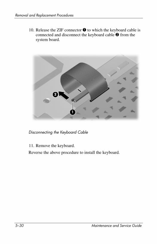
Removal and Replacement Procedures
10. Release the ZIF connector 1 to which the keyboard cable is connected and disconnect the keyboard cable 2 from the system board.
Disconnecting the Keyboard Cable
11. Remove the keyboard.
Reverse the above procedure to install the keyboard.
5–30 Maintenance and Service Guide
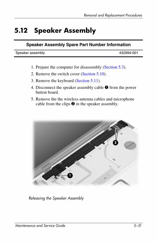
Removal and Replacement Procedures
5.12 Speaker Assembly
1. Prepare the computer for disassembly (Section 5.3).
2. Remove the switch cover (Section 5.10).
3. Remove the keyboard (Section 5.11).
4. Disconnect the speaker assembly cable 1 from the power button board.
5. Remove the the wireless antenna cables and microphone cable from the clips 2 in the speaker assembly.
Releasing the Speaker Assembly
Speaker Assembly Spare Part Number Information
Speaker assembly 432994-001
Maintenance and Service Guide 5–31
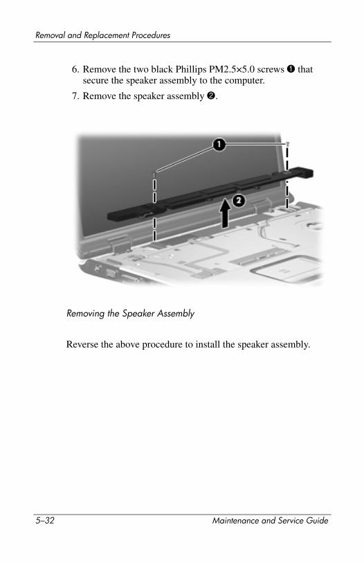
Removal and Replacement Procedures
6. Remove the two black Phillips PM2.5×5.0 screws 1 that secure the speaker assembly to the computer.
7. Remove the speaker assembly 2.
Removing the Speaker Assembly
Reverse the above procedure to install the speaker assembly.
5–32 Maintenance and Service Guide

Removal and Replacement Procedures
5.13 Power Button Board
1. Prepare the computer for disassembly (Section 5.3).
2. Remove the switch cover (Section 5.10).
3. Remove the keyboard (Section 5.11).
4. Disconnect the following cables from the power button board:
1 Display lid switch module cable
2 Microphone cable
3 Speaker assembly cable
5. Release the ZIF connector 4 to which the power button board cable is connected and disconnect the cable 5.
Disconnecting the Power Button Board Cables
Power Button Board Spare Part Number Information
Power button board (includes power button board cable) 432987-001
Maintenance and Service Guide 5–33
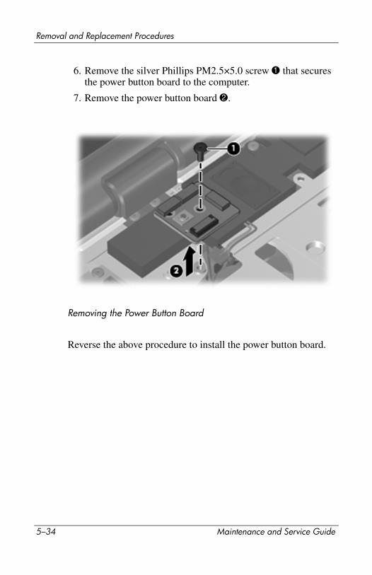
Removal and Replacement Procedures
6. Remove the silver Phillips PM2.5×5.0 screw 1 that secures the power button board to the computer.
7. Remove the power button board 2.
Removing the Power Button Board
Reverse the above procedure to install the power button board.
5–34 Maintenance and Service Guide
Removal and Replacement Procedures
5.14 Display Assembly
1. Prepare the computer for disassembly (Section 5.3) and remove the following components:
❏ Memory module compartment cover (Section 5.8)
❏ Switch cover (Section 5.10)
❏ Keyboard (Section 5.11)
❏ Speaker assembly (Section 5.12)
Display Assembly Spare Part Number Information
For use with full-featured computer models (includes camera, camera cable, and microphones)17.0-inch, SXGA+, TFT Single Lamp with BrightView17.0-inch, WXGA+, TFT Single Lamp with BrightView17.0-inch, WXGA+, TFT Dual Lamp with BrightView
432947-001432946-001432948-001
For use with de-featured computer models (includes microphones)17.0-inch, SXGA+, TFT Single Lamp with BrightView17.0-inch, WXGA+, TFT Single Lamp with BrightView17.0-inch, WXGA+, TFT Dual Lamp with BrightView
432950-001432949-001432951-001
Maintenance and Service Guide 5–35
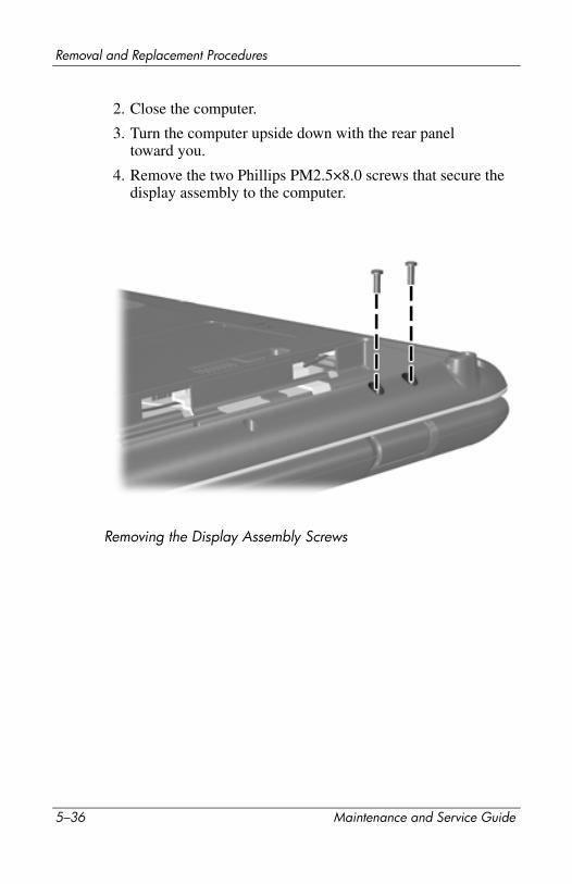
Removal and Replacement Procedures
2. Close the computer.
3. Turn the computer upside down with the rear panel toward you.
4. Remove the two Phillips PM2.5×8.0 screws that secure the display assembly to the computer.
Removing the Display Assembly Screws
5–36 Maintenance and Service Guide

Removal and Replacement Procedures
5. Turn the computer display-side up with the front toward you.
6. Open the computer to an upright position.
7. Disconnect the display cable 1 from the system board and the microphone cable 2 from the power button board.
8. Remove the wireless antenna cables and the camera cable from the clips 3 in the top cover.
9. Disconnect the camera cable 4 from the system board.
Disconnecting the Display Cables
Maintenance and Service Guide 5–37
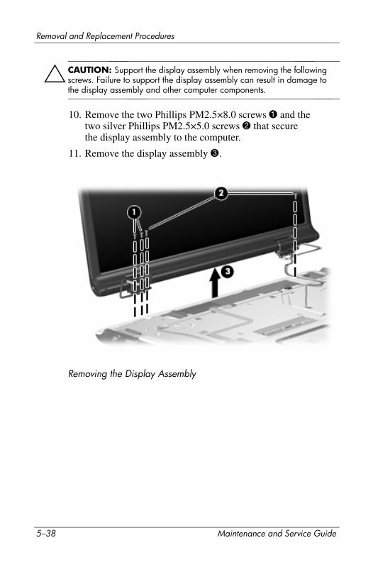
Removal and Replacement Procedures
ÄCAUTION: Support the display assembly when removing the following screws. Failure to support the display assembly can result in damage to the display assembly and other computer components.
10. Remove the two Phillips PM2.5×8.0 screws 1 and the two silver Phillips PM2.5×5.0 screws 2 that secure the display assembly to the computer.
11. Remove the display assembly 3.
Removing the Display Assembly
5–38 Maintenance and Service Guide

Removal and Replacement Procedures
12. Remove the following:
1 Three rubber screw covers on the display bezel top edge
2 Two rubber screw covers on the display bezel bottom edge
3 Five Phillips PM2.5×8.0 screws
✎ The display rubber screw covers are included in the Display Screw Kit, spare part number 432967-001.
Removing the Display Bezel Screws
Maintenance and Service Guide 5–39
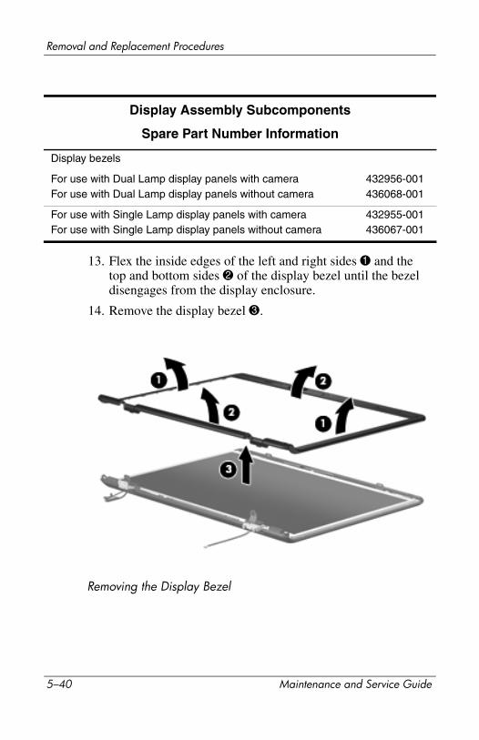
Removal and Replacement Procedures
13. Flex the inside edges of the left and right sides 1 and the top and bottom sides 2 of the display bezel until the bezel disengages from the display enclosure.
14. Remove the display bezel 3.
Removing the Display Bezel
Display Assembly Subcomponents
Spare Part Number Information
Display bezels
For use with Dual Lamp display panels with cameraFor use with Dual Lamp display panels without camera
432956-001436068-001
For use with Single Lamp display panels with cameraFor use with Single Lamp display panels without camera
432955-001436067-001
5–40 Maintenance and Service Guide
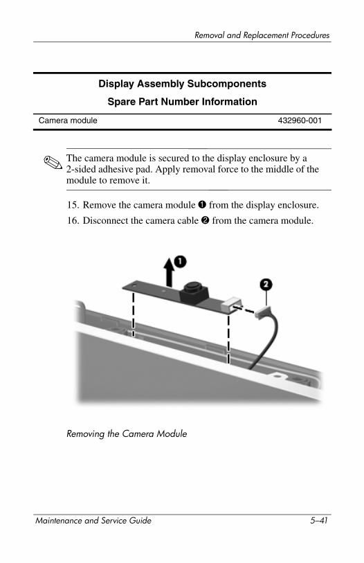
Removal and Replacement Procedures
✎ The camera module is secured to the display enclosure by a 2-sided adhesive pad. Apply removal force to the middle of the module to remove it.
15. Remove the camera module 1 from the display enclosure.
16. Disconnect the camera cable 2 from the camera module.
Removing the Camera Module
Display Assembly Subcomponents
Spare Part Number Information
Camera module 432960-001
Maintenance and Service Guide 5–41
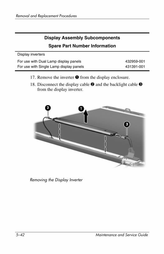
Removal and Replacement Procedures
17. Remove the inverter 1 from the display enclosure.
18. Disconnect the display cable 2 and the backlight cable 3 from the display inverter.
Removing the Display Inverter
Display Assembly Subcomponents
Spare Part Number Information
Display inverters
For use with Dual Lamp display panelsFor use with Single Lamp display panels
432959-001431391-001
5–42 Maintenance and Service Guide
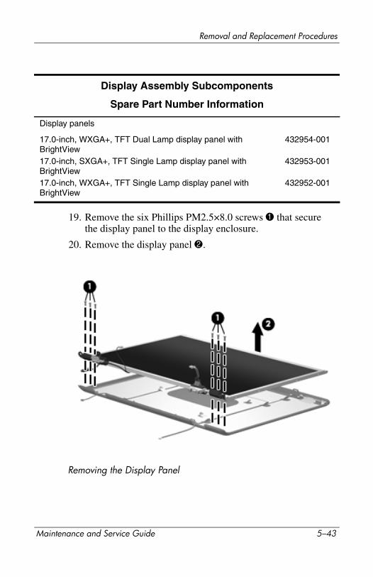
Removal and Replacement Procedures
19. Remove the six Phillips PM2.5×8.0 screws 1 that secure the display panel to the display enclosure.
20. Remove the display panel 2.
Removing the Display Panel
Display Assembly Subcomponents
Spare Part Number Information
Display panels
17.0-inch, WXGA+, TFT Dual Lamp display panel with BrightView17.0-inch, SXGA+, TFT Single Lamp display panel with BrightView17.0-inch, WXGA+, TFT Single Lamp display panel with BrightView
432954-001
432953-001
432952-001
Maintenance and Service Guide 5–43

Removal and Replacement Procedures
21. Remove the two Phillips PM2.0×3.0 screws 1 that secure each display hinge to the display enclosure.
22. Remove the display hinges 2.
23. Slide the left and right display hinge covers 3 off of the display hinges.
Removing the Display Hinges
Display Assembly Subcomponents
Spare Part Number Information
Display Hinge Kits
For use with Dual Lamp display panelsFor use with Single Lamp display panels
432964-001432963-001
Display hinge covers 432965-001
5–44 Maintenance and Service Guide
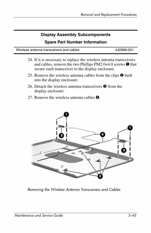
Removal and Replacement Procedures
24. If it is necessary to replace the wireless antenna transceivers and cables, remove the two Phillips PM2.0×4.0 screws 1 that secure each transceiver to the display enclosure.
25. Remove the wireless antenna cables from the clips 2 built into the display enclosure.
26. Detach the wireless antenna transceivers 3 from the display enclosure.
27. Remove the wireless antenna cables 4.
Removing the Wireless Antenna Transceivers and Cables
Display Assembly Subcomponents
Spare Part Number Information
Wireless antenna transceivers and cables 432966-001
Maintenance and Service Guide 5–45

Removal and Replacement Procedures
28. If it is necessary to replace the microphones and cables, release the retention tabs 1 built into the display enclosure that secure the microphone cables to the display enclosure.
29. Remove the microphone receivers 2 from the clips in the display enclosure.
30. Remove the microphone cables 3 from the display enclosure.
Removing the Microphones
Display Assembly Subcomponents
Spare Part Number Information
Microphones 432961-001
5–46 Maintenance and Service Guide
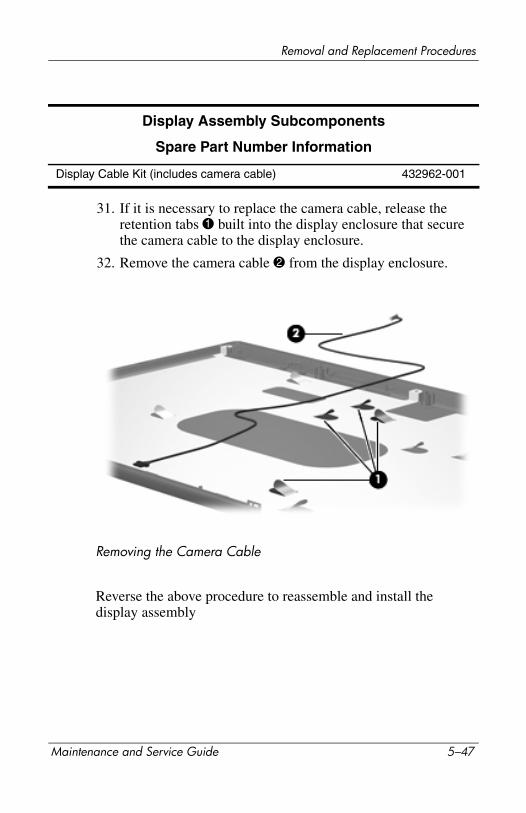
Removal and Replacement Procedures
31. If it is necessary to replace the camera cable, release the retention tabs 1 built into the display enclosure that secure the camera cable to the display enclosure.
32. Remove the camera cable 2 from the display enclosure.
Removing the Camera Cable
Reverse the above procedure to reassemble and install the display assembly
Display Assembly Subcomponents
Spare Part Number Information
Display Cable Kit (includes camera cable) 432962-001
Maintenance and Service Guide 5–47

Removal and Replacement Procedures
5.15 Top Cover
1. Prepare the computer for disassembly (Section 5.3) and remove the following components:
❏ Hard drive (Section 5.4)
❏ Optical drive (Section 5.9)
❏ Switch cover (Section 5.10)
❏ Keyboard (Section 5.11)
❏ Speaker assembly (Section 5.12)
❏ Display assembly (Section 5.14)
Top Cover Spare Part Number Information
Top cover (includes TouchPad and TouchPad cable) for use with model dv9000Top cover (includes TouchPad and TouchPad cable) for use with dv9200
432977-001
442919-001
5–48 Maintenance and Service Guide
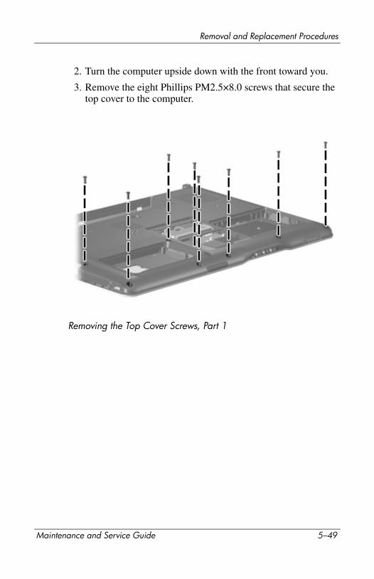
Removal and Replacement Procedures
2. Turn the computer upside down with the front toward you.
3. Remove the eight Phillips PM2.5×8.0 screws that secure the top cover to the computer.
Removing the Top Cover Screws, Part 1
Maintenance and Service Guide 5–49

Removal and Replacement Procedures
4. Remove the four silver Phillips PM2.5×5.0 screws that secure the top cover to the computer.
Removing the Top Cover Screws, Part 2
5–50 Maintenance and Service Guide
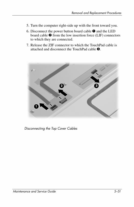
Removal and Replacement Procedures
5. Turn the computer right-side up with the front toward you.
6. Disconnect the power button board cable 1 and the LED board cable 2 from the low insertion force (LIF) connectors to which they are connected.
7. Release the ZIF connector to which the TouchPad cable is attached and disconnect the TouchPad cable 3.
Disconnecting the Top Cover Cables
Maintenance and Service Guide 5–51

Removal and Replacement Procedures
8. Remove the five Phillips PM2.5×8.0 screws 1 and the silver Phillips PM2.5×5.0 screw 2 that secures the top cover to the computer.
Removing the Top Cover Screws, Part 3
5–52 Maintenance and Service Guide

Removal and Replacement Procedures
9. Lift the rear edge of the top cover until it disengages from the computer, and remove the top cover.
Removing the Top Cover
Reverse the above procedure to install the top cover.
Maintenance and Service Guide 5–53
Removal and Replacement Procedures
5.16 Wireless Switch Board
1. Prepare the computer for disassembly (Section 5.3) and remove the following components:
❏ Hard drive (Section 5.4)
❏ Optical drive (Section 5.9)
❏ Switch cover (Section 5.10)
❏ Keyboard (Section 5.11)
❏ Speaker assembly (Section 5.12)
❏ Display assembly (Section 5.14)
❏ Top cover (Section 5.15)
Wireless Switch Board Spare Part Number Information
Wireless switch board 432991-001
5–54 Maintenance and Service Guide
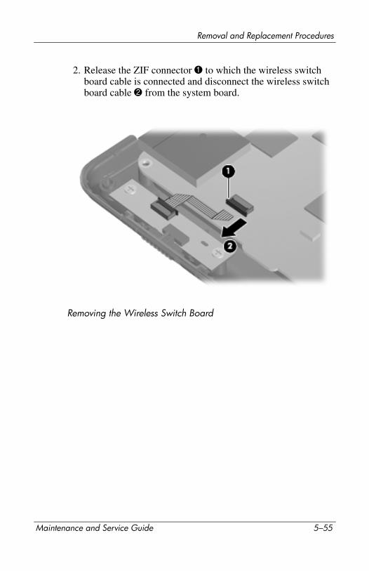
Removal and Replacement Procedures
2. Release the ZIF connector 1 to which the wireless switch board cable is connected and disconnect the wireless switch board cable 2 from the system board.
Removing the Wireless Switch Board
Maintenance and Service Guide 5–55
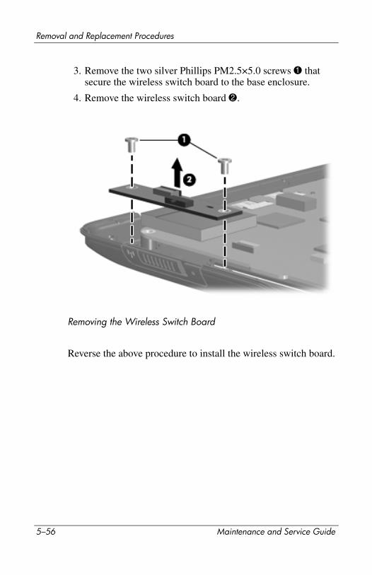
Removal and Replacement Procedures
3. Remove the two silver Phillips PM2.5×5.0 screws 1 that secure the wireless switch board to the base enclosure.
4. Remove the wireless switch board 2.
Removing the Wireless Switch Board
Reverse the above procedure to install the wireless switch board.
5–56 Maintenance and Service Guide
Removal and Replacement Procedures
5.17 Audio Board
1. Prepare the computer for disassembly (Section 5.3) and remove the following components:
❏ Hard drive (Section 5.4)
❏ Optical drive (Section 5.9)
❏ Switch cover (Section 5.10)
❏ Keyboard (Section 5.11)
❏ Speaker assembly (Section 5.12)
❏ Display assembly (Section 5.14)
❏ Top cover (Section 5.15)
Audio Board Spare Part Number Information
Audio board (includes audio board cable and infrared lens) for use with dv9000Audio board (includes audio board cable and infrared lens) for use with dv9200
432986-001
438369-001
Maintenance and Service Guide 5–57
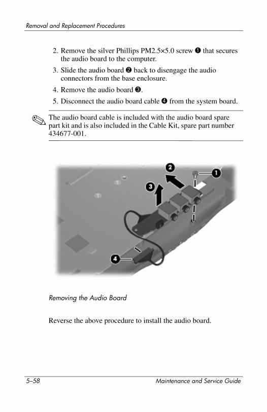
Removal and Replacement Procedures
2. Remove the silver Phillips PM2.5×5.0 screw 1 that secures the audio board to the computer.
3. Slide the audio board 2 back to disengage the audio connectors from the base enclosure.
4. Remove the audio board 3.
5. Disconnect the audio board cable 4 from the system board.
✎ The audio board cable is included with the audio board spare part kit and is also included in the Cable Kit, spare part number 434677-001.
Removing the Audio Board
Reverse the above procedure to install the audio board.
5–58 Maintenance and Service Guide

Removal and Replacement Procedures
5.18 Bluetooth Module
1. Prepare the computer for disassembly (Section 5.3) and remove the following components:
❏ Hard drive (Section 5.4)
❏ Optical drive (Section 5.9)
❏ Switch cover (Section 5.10)
❏ Keyboard (Section 5.11)
❏ Speaker assembly (Section 5.12)
❏ Display assembly (Section 5.14)
❏ Top cover (Section 5.15)
Bluetooth Module Spare Part Number Information
Bluetooth module (includes Bluetooth module cable) 412766-001
Maintenance and Service Guide 5–59

Removal and Replacement Procedures
2. Disconnect the Bluetooth module cable 1 from the system board.
✎ The Bluetooth module cable is included with the Bluetooth module spare part kit and is also included in the Cable Kit, spare part number 434677-001.
3. Route the Bluetooth module cable 2 under the system board.
4. Remove the two silver Phillips PM2.0×3.0 screws 3 that secure the Bluetooth module to the base enclosure.
5. Remove the Bluetooth module 4.
Removing the Bluetooth Module
Reverse the above procedure to install the Bluetooth module.
5–60 Maintenance and Service Guide
Removal and Replacement Procedures
5.19 USB/Magnetic Board
1. Prepare the computer for disassembly (Section 5.3) and remove the following components:
❏ Hard drive (Section 5.4)
❏ Optical drive (Section 5.9)
❏ Switch cover (Section 5.10)
❏ Keyboard (Section 5.11)
❏ Speaker assembly (Section 5.12)
❏ Display assembly (Section 5.14)
❏ Top cover (Section 5.15)
USB/Magnetic Board Spare Part Number Information
USB/magnetic board (includes USB/magnetic board cable) for use with dv9000USB/magnetic board (includes USB/magnetic board cable) for use with dv9200
432990-001
438370-001
Maintenance and Service Guide 5–61
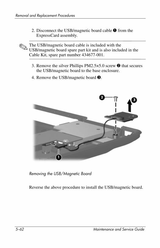
Removal and Replacement Procedures
2. Disconnect the USB/magnetic board cable 1 from the ExpressCard assembly.
✎ The USB/magnetic board cable is included with the USB/magnetic board spare part kit and is also included in the Cable Kit, spare part number 434677-001.
3. Remove the silver Phillips PM2.5×5.0 screw 2 that secures the USB/magnetic board to the base enclosure.
4. Remove the USB/magnetic board 3.
Removing the USB/Magnetic Board
Reverse the above procedure to install the USB/magnetic board.
5–62 Maintenance and Service Guide
Removal and Replacement Procedures
5.20 ExpressCard Assembly
1. Prepare the computer for disassembly (Section 5.3) and remove the following components:
❏ Hard drive (Section 5.4)
❏ Optical drive (Section 5.9)
❏ Switch cover (Section 5.10)
❏ Keyboard (Section 5.11)
❏ Speaker assembly (Section 5.12)
❏ Display assembly (Section 5.14)
❏ Top cover (Section 5.15)
❏ USB/magnetic board (Section 5.19)
ExpressCard Assembly Spare Part Number Information
ExpressCard assembly 432988-001
Maintenance and Service Guide 5–63
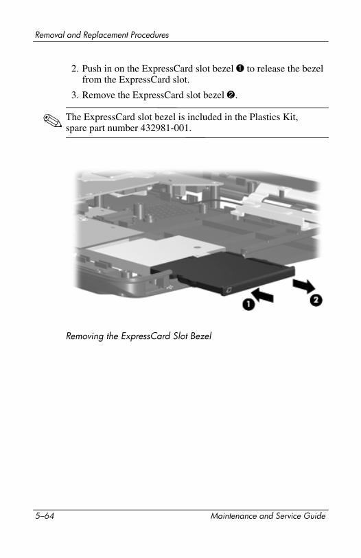
Removal and Replacement Procedures
2. Push in on the ExpressCard slot bezel 1 to release the bezel from the ExpressCard slot.
3. Remove the ExpressCard slot bezel 2.
✎ The ExpressCard slot bezel is included in the Plastics Kit, spare part number 432981-001.
Removing the ExpressCard Slot Bezel
5–64 Maintenance and Service Guide
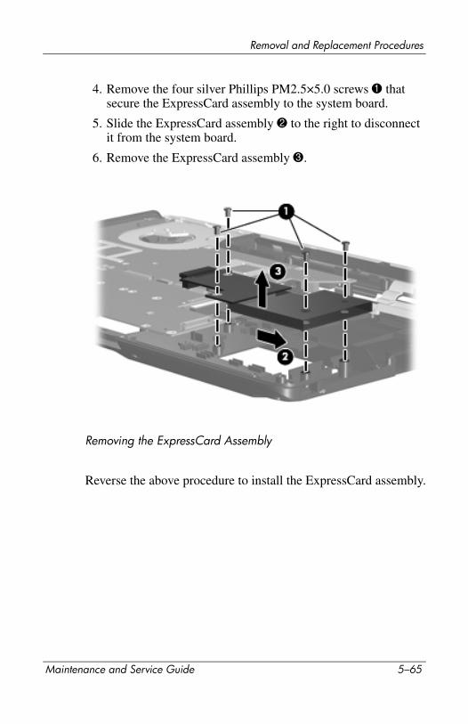
Removal and Replacement Procedures
4. Remove the four silver Phillips PM2.5×5.0 screws 1 that secure the ExpressCard assembly to the system board.
5. Slide the ExpressCard assembly 2 to the right to disconnect it from the system board.
6. Remove the ExpressCard assembly 3.
Removing the ExpressCard Assembly
Reverse the above procedure to install the ExpressCard assembly.
Maintenance and Service Guide 5–65

Removal and Replacement Procedures
5.21 Top Cover Support Trim
1. Prepare the computer for disassembly (Section 5.3) and remove the following components:
❏ Hard drive (Section 5.4)
❏ Optical drive (Section 5.9)
❏ Switch cover (Section 5.10)
❏ Keyboard (Section 5.11)
❏ Speaker assembly (Section 5.12)
❏ Display assembly (Section 5.14)
❏ Top cover (Section 5.15)
Top Cover Support Trim Spare Part Number Information
Top cover support trim 432978-001
5–66 Maintenance and Service Guide
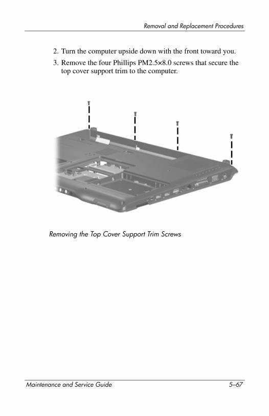
Removal and Replacement Procedures
2. Turn the computer upside down with the front toward you.
3. Remove the four Phillips PM2.5×8.0 screws that secure the top cover support trim to the computer.
Removing the Top Cover Support Trim Screws
Maintenance and Service Guide 5–67
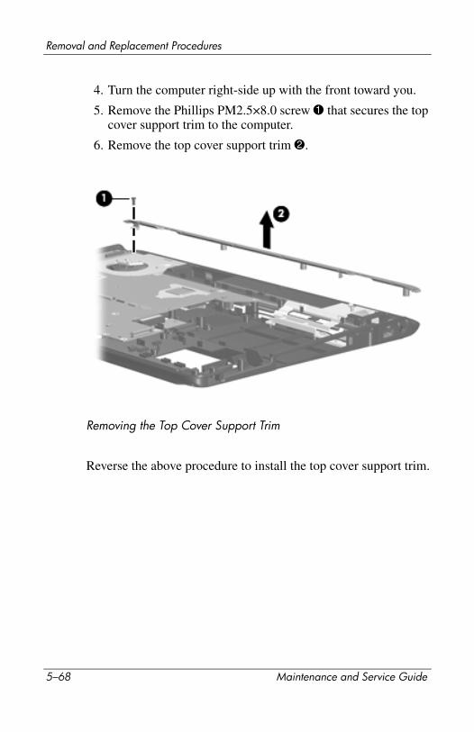
Removal and Replacement Procedures
4. Turn the computer right-side up with the front toward you.
5. Remove the Phillips PM2.5×8.0 screw 1 that secures the top cover support trim to the computer.
6. Remove the top cover support trim 2.
Removing the Top Cover Support Trim
Reverse the above procedure to install the top cover support trim.
5–68 Maintenance and Service Guide
Removal and Replacement Procedures
5.22 Display Lid Switch Module
1. Prepare the computer for disassembly (Section 5.3) and remove the following components:
❏ Hard drive (Section 5.4)
❏ Optical drive (Section 5.9)
❏ Switch cover (Section 5.10)
❏ Keyboard (Section 5.11)
❏ Speaker assembly (Section 5.12)
❏ Display assembly (Section 5.14)
❏ Top cover (Section 5.15)
❏ Top cover support trim (Section 5.21)
Display Lid Switch Module Spare Part Number Information
Display lid switch module 432993-001
Maintenance and Service Guide 5–69
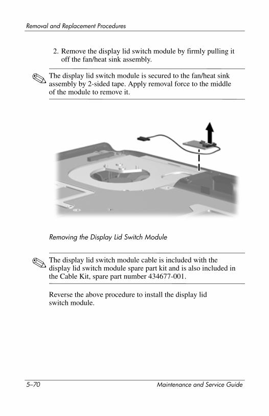
Removal and Replacement Procedures
2. Remove the display lid switch module by firmly pulling it off the fan/heat sink assembly.
✎ The display lid switch module is secured to the fan/heat sink assembly by 2-sided tape. Apply removal force to the middle of the module to remove it.
Removing the Display Lid Switch Module
✎ The display lid switch module cable is included with the display lid switch module spare part kit and is also included in the Cable Kit, spare part number 434677-001.
Reverse the above procedure to install the display lid switch module.
5–70 Maintenance and Service Guide
Removal and Replacement Procedures
5.23 Power Connector Assembly
1. Prepare the computer for disassembly (Section 5.3) and remove the following components:
❏ Hard drive (Section 5.4)
❏ Optical drive (Section 5.9)
❏ Switch cover (Section 5.10)
❏ Keyboard (Section 5.11)
❏ Speaker assembly (Section 5.12)
❏ Display assembly (Section 5.14)
❏ Top cover (Section 5.15)
Power Connector Assembly Spare Part Number Information
Power connector assembly (includes power connector assembly cable and power connector assembly bracket)
432985-001
USB board 432989-001
Maintenance and Service Guide 5–71
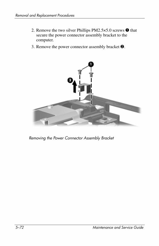
Removal and Replacement Procedures
2. Remove the two silver Phillips PM2.5×5.0 screws 1 that secure the power connector assembly bracket to the computer.
3. Remove the power connector assembly bracket 2.
Removing the Power Connector Assembly Bracket
5–72 Maintenance and Service Guide
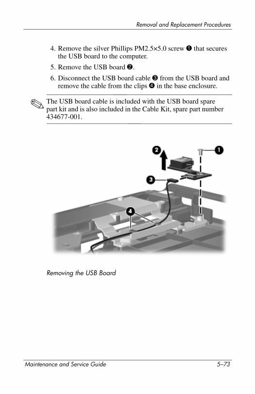
Removal and Replacement Procedures
4. Remove the silver Phillips PM2.5×5.0 screw 1 that secures the USB board to the computer.
5. Remove the USB board 2.
6. Disconnect the USB board cable 3 from the USB board and remove the cable from the clips 4 in the base enclosure.
✎ The USB board cable is included with the USB board spare part kit and is also included in the Cable Kit, spare part number 434677-001.
Removing the USB Board
Maintenance and Service Guide 5–73
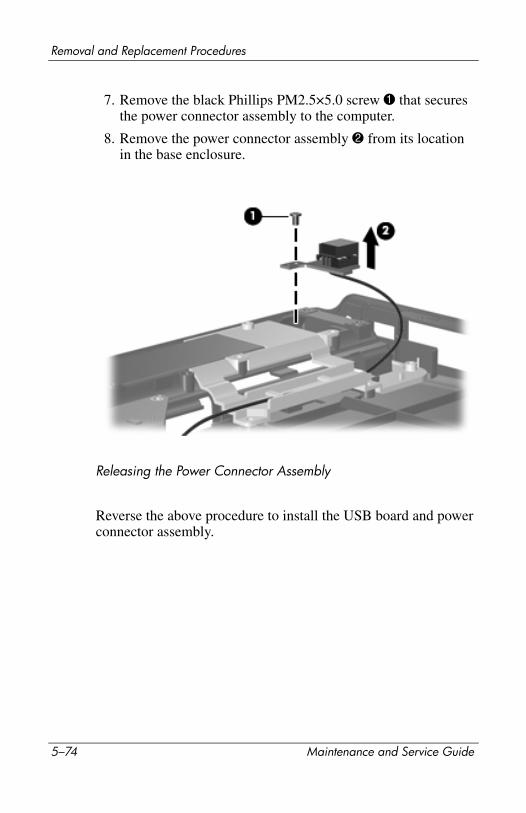
Removal and Replacement Procedures
7. Remove the black Phillips PM2.5×5.0 screw 1 that secures the power connector assembly to the computer.
8. Remove the power connector assembly 2 from its location in the base enclosure.
Releasing the Power Connector Assembly
Reverse the above procedure to install the USB board and power connector assembly.
5–74 Maintenance and Service Guide

Removal and Replacement Procedures
5.24 System Board
✎ When replacing the system board, ensure that the following components are removed from the defective system board and installed on the replacement system board:■ Memory modules (Section 5.6)■ RTC battery (Section 5.7)■ Mini Card module (Section 5.8)■ Bluetooth module (Section 5.18)■ ExpressCard assembly (Section 5.20)■ Optical drive connector module (Section 5.24)■ Fan/heat sink assembly (Section 5.25)■ Processor (Section 5.26)
1. Prepare the computer for disassembly (Section 5.3) and remove the following components:
❏ Hard drive (Section 5.4)
❏ Optical drive (Section 5.9)
❏ Switch cover (Section 5.10)
❏ Keyboard (Section 5.11)
❏ Speaker assembly (Section 5.12)
❏ Display assembly (Section 5.14)
System Board Spare Part Number Information
For use with only computer models using Intel processors:
G73 (includes 512-MB of video RAM)G73M (includes 256-MB of video RAM)G73 (includes 512 MB of video RAM) - for Germany onlyG73 (includes 256 MB of video RAM) - for EMEA only
434660-001434659-001441620-001445178-001
For use only with UMA computer models using AMD processors 444002-001
Maintenance and Service Guide 5–75
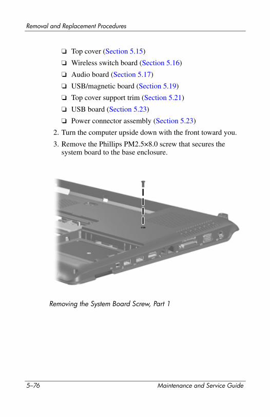
Removal and Replacement Procedures
❏ Top cover (Section 5.15)
❏ Wireless switch board (Section 5.16)
❏ Audio board (Section 5.17)
❏ USB/magnetic board (Section 5.19)
❏ Top cover support trim (Section 5.21)
❏ USB board (Section 5.23)
❏ Power connector assembly (Section 5.23)
2. Turn the computer upside down with the front toward you.
3. Remove the Phillips PM2.5×8.0 screw that secures the system board to the base enclosure.
Removing the System Board Screw, Part 1
5–76 Maintenance and Service Guide
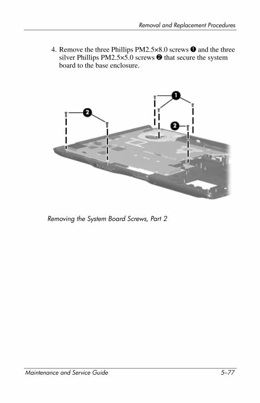
Removal and Replacement Procedures
4. Remove the three Phillips PM2.5×8.0 screws 1 and the three silver Phillips PM2.5×5.0 screws 2 that secure the system board to the base enclosure.
Removing the System Board Screws, Part 2
Maintenance and Service Guide 5–77
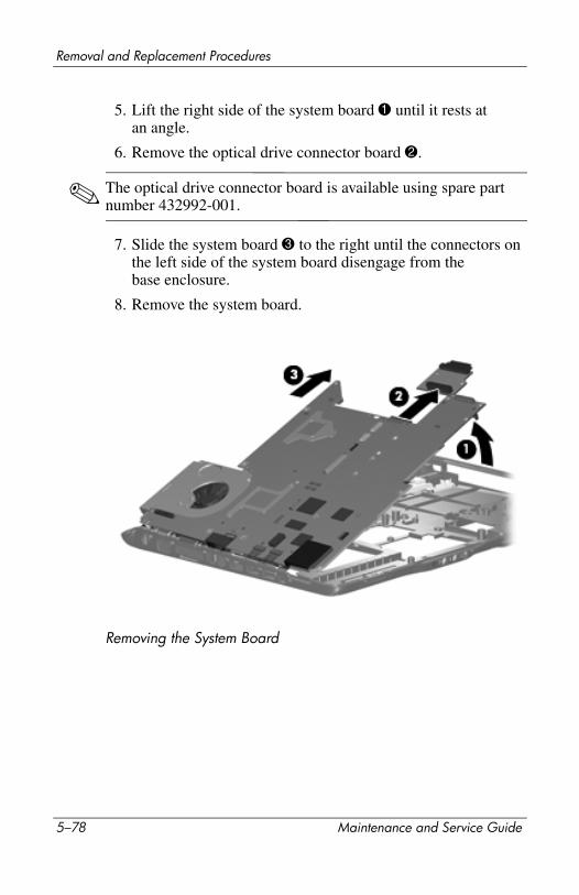
Removal and Replacement Procedures
5. Lift the right side of the system board 1 until it rests at an angle.
6. Remove the optical drive connector board 2.
✎ The optical drive connector board is available using spare part number 432992-001.
7. Slide the system board 3 to the right until the connectors on the left side of the system board disengage from the base enclosure.
8. Remove the system board.
Removing the System Board
5–78 Maintenance and Service Guide
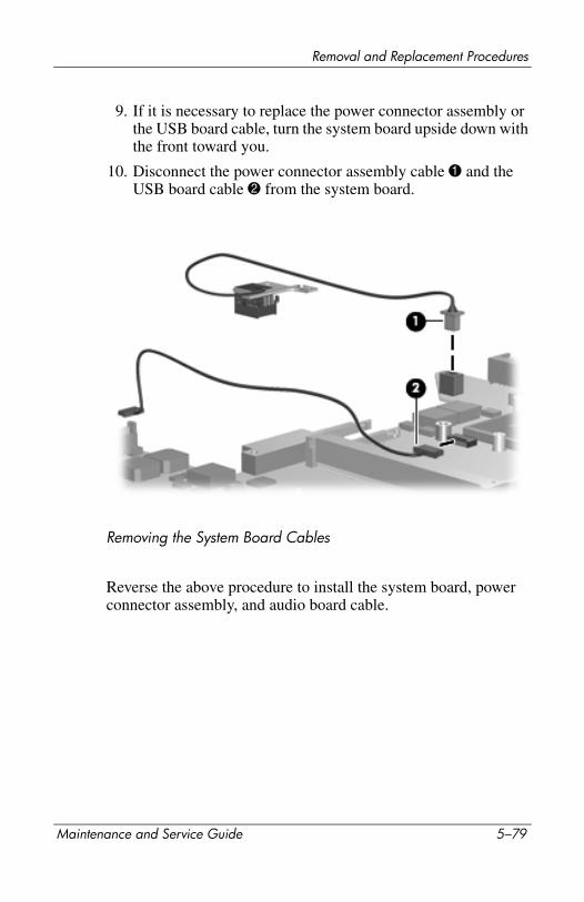
Removal and Replacement Procedures
9. If it is necessary to replace the power connector assembly or the USB board cable, turn the system board upside down with the front toward you.
10. Disconnect the power connector assembly cable 1 and the USB board cable 2 from the system board.
Removing the System Board Cables
Reverse the above procedure to install the system board, power connector assembly, and audio board cable.
Maintenance and Service Guide 5–79
Removal and Replacement Procedures
5.25 Fan/Heat Sink Assembly
✎ When replacing the fan/heat sink assembly, be sure the display lid switch module is removed from the defective fan/heat sink assembly and installed on the replacement fan/heat sink assembly. Refer to Section 5.22, “Display Lid Switch Module,” for display lid switch module removal information.
1. Prepare the computer for disassembly (Section 5.3) and remove the following components:
❏ Hard drive (Section 5.4)
❏ Optical drive (Section 5.9)
❏ Switch cover (Section 5.10)
❏ Keyboard (Section 5.11)
❏ Speaker assembly (Section 5.12)
❏ Display assembly (Section 5.14)
❏ Top cover (Section 5.15)
❏ Wireless switch board (Section 5.16)
❏ Audio board (Section 5.17)
❏ USB/magnetic board (Section 5.19)
❏ Top cover support trim (Section 5.21)
❏ USB board (Section 5.23)
❏ Power connector assembly (Section 5.23)
❏ System board (Section 5.24)
Fan/Heat Sink Assembly Spare Part Number Information
For use only with computer models using Intel processors 434678-001
For use only with computer models using AMD processors 438606-001
5–80 Maintenance and Service Guide

Removal and Replacement Procedures
2. Turn the system board upside down with the expansion port and external monitor port toward you.
3. Disconnect the fan cable 1 from the system board.
4. Loosen the four captive Phillips PM2.5×6.0 screws 2 that secure the fan/heat sink assembly to the system board.
5. Remove the fan/heat sink assembly 3.
Removing the Fan/Heat Sink Assembly
Maintenance and Service Guide 5–81
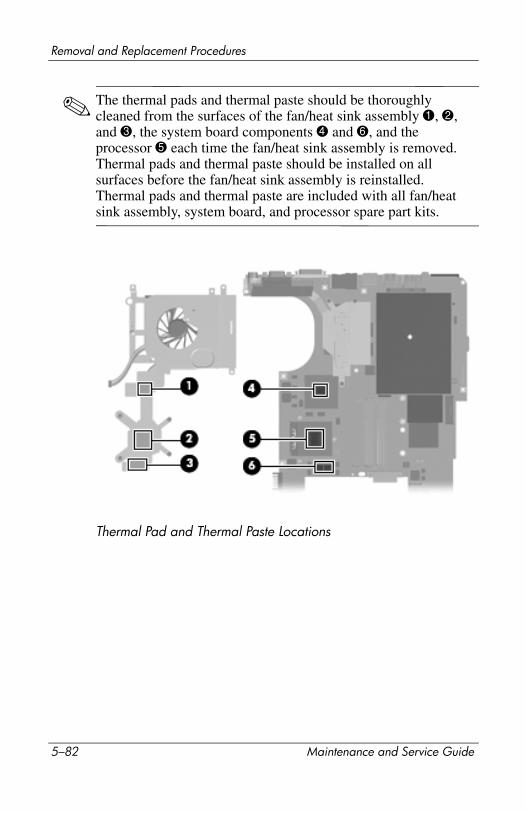
Removal and Replacement Procedures
✎ The thermal pads and thermal paste should be thoroughly cleaned from the surfaces of the fan/heat sink assembly 1, 2, and 3, the system board components 4 and 6, and the processor 5 each time the fan/heat sink assembly is removed. Thermal pads and thermal paste should be installed on all surfaces before the fan/heat sink assembly is reinstalled. Thermal pads and thermal paste are included with all fan/heat sink assembly, system board, and processor spare part kits.
Thermal Pad and Thermal Paste Locations
5–82 Maintenance and Service Guide
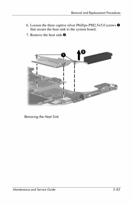
Removal and Replacement Procedures
6. Loosen the three captive silver Phillips PM2.5×5.0 screws 1 that secure the heat sink to the system board.
7. Remove the heat sink 2.
Removing the Heat Sink
Maintenance and Service Guide 5–83
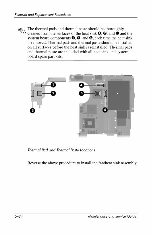
Removal and Replacement Procedures
✎ The thermal pads and thermal paste should be thoroughly cleaned from the surfaces of the heat sink 1, 2, and 3 and the system board components 4, 5, and 6, each time the heat sink is removed. Thermal pads and thermal paste should be installed on all surfaces before the heat sink is reinstalled. Thermal pads and thermal paste are included with all heat sink and system board spare part kits.
Thermal Pad and Thermal Paste Locations
Reverse the above procedure to install the fan/heat sink assembly.
5–84 Maintenance and Service Guide
Removal and Replacement Procedures
5.26 Processor
1. Prepare the computer for disassembly (Section 5.3) and remove the following components:
❏ Hard drive (Section 5.4)
❏ Optical drive (Section 5.9)
Processor Spare Part Number Information
Processors (include thermal pads and thermal paste)
Intel Core Duo T7200 (2.00-GHz)Intel Core Duo T5600 (1.83-GHz)Intel Core Duo T5500 (1.66-GHz), for dv9200 modelsIntel Core Duo T5300 (1.73-GHz), for dv9200 modelsIntel Core Duo T5200 (1.66-GHz), for dv9200 modelsIntel Core Duo T2250 (1.66-GHz), for dv9200 modelsIntel Core Duo T2350 (1.86-GHz)Intel Core Duo T5200 (1.66-GHz)Intel Pentium Dual-Core T2080 (1.73-GHz)
434730-001434731-011436157-001446814-001436900-001430897-001441762-001436902-001446812-001
AMD Turion TL-64 (2.2-GHz)AMD Turion TL-60 (2.0-GHz)AMD Turion TL-58 (1.9-GHz)AMD Turion TL-56 (1.8-GHz)AMD Athlon 64 TK-53 (1.7-GHz)
441535-001436257-001448561-001431373-001451013-001
Processor bracket 7.9 (not illustrated), for use with the following processors: 434730-001 434731-001 436157-001 436900-001 446814-001
450370-001
Processor bracket 8.1 (not illustrated), for use with the following processors: 430897-001, 446812-001, 441762-001
450371-001
Maintenance and Service Guide 5–85
Removal and Replacement Procedures
❏ Switch cover (Section 5.10)
❏ Keyboard (Section 5.11)
❏ Speaker assembly (Section 5.12)
❏ Display assembly (Section 5.14)
❏ Top cover (Section 5.15)
❏ Wireless switch board (Section 5.16)
❏ Audio board (Section 5.17)
❏ USB/magnetic board (Section 5.19)
❏ Top cover support trim (Section 5.21)
❏ USB board (Section 5.23)
❏ Power connector assembly (Section 5.23)
❏ System board (Section 5.24)
❏ Fan/heat sink assembly (Section 5.25)
5–86 Maintenance and Service Guide
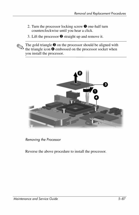
Removal and Replacement Procedures
2. Turn the processor locking screw 1 one-half turn counterclockwise until you hear a click.
3. Lift the processor 2 straight up and remove it.
✎ The gold triangle 3 on the processor should be aligned with the triangle icon 4 embossed on the processor socket when you install the processor.
Removing the Processor
Reverse the above procedure to install the processor.
Maintenance and Service Guide 5–87
Removal and Replacement Procedures
5–88 Maintenance and Service Guide
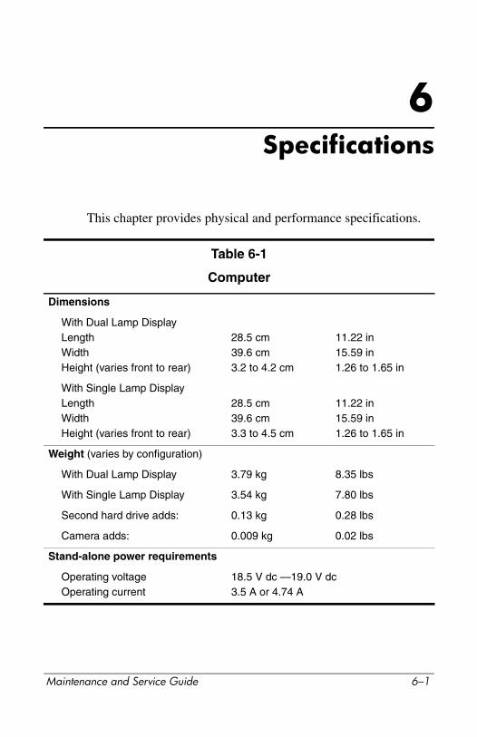
6Specifications
This chapter provides physical and performance specifications.
Table 6-1
Computer
Dimensions
With Dual Lamp DisplayLengthWidthHeight (varies front to rear)
28.5 cm39.6 cm3.2 to 4.2 cm
11.22 in15.59 in1.26 to 1.65 in
With Single Lamp DisplayLengthWidthHeight (varies front to rear)
28.5 cm39.6 cm3.3 to 4.5 cm
11.22 in15.59 in1.26 to 1.65 in
Weight (varies by configuration)
With Dual Lamp Display 3.79 kg 8.35 lbs
With Single Lamp Display 3.54 kg 7.80 lbs
Second hard drive adds: 0.13 kg 0.28 lbs
Camera adds: 0.009 kg 0.02 lbs
Stand-alone power requirements
Operating voltageOperating current
18.5 V dc —19.0 V dc3.5 A or 4.74 A
Maintenance and Service Guide 6–1

Specifications
Temperature
Operating*Nonoperating
5°C to 35°C-20°C to 60°C
41°F to 95°F-4°F to 140°F
Relative humidity (noncondensing)
OperatingNonoperating
10% to 90%5% to 95%, 38.7°C (101.6°F) maximum wet bulb temperature
Maximum altitude (unpressurized)
Operating (14.7 to 10.1 psia)Nonoperating (14.7 to 4.4 psia)
-15 m to 3,048 m-15 m to 12,192 m
-50 ft to 10,000 ft-50 ft to 40,000 ft
Shock
OperatingNonoperating
125 g, 2 ms, half-sine200 g, 2 ms, half-sine
Random Vibration
Operating
Nonoperating
0.75 g zero-to-peak, 10 Hz to 500 Hz, 0.25 oct/min sweep rate1.50 g zero-to-peak, 10 Hz to 500 Hz, 0.5 oct/min sweep rate
*Applicable product safety standards specify thermal limits for plastic surfaces. The computer operates well within this range of temperatures.
Table 6-1
Computer (Continued)
6–2 Maintenance and Service Guide
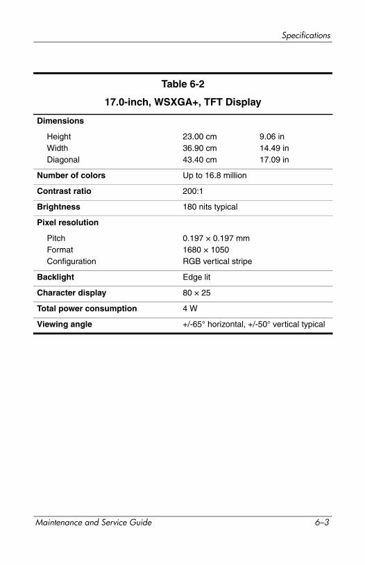
Specifications
Table 6-2
17.0-inch, WSXGA+, TFT Display
Dimensions
HeightWidthDiagonal
23.00 cm36.90 cm43.40 cm
9.06 in14.49 in17.09 in
Number of colors Up to 16.8 million
Contrast ratio 200:1
Brightness 180 nits typical
Pixel resolution
PitchFormatConfiguration
0.197 × 0.197 mm1680 × 1050RGB vertical stripe
Backlight Edge lit
Character display 80 × 25
Total power consumption 4 W
Viewing angle +/-65° horizontal, +/-50° vertical typical
Maintenance and Service Guide 6–3
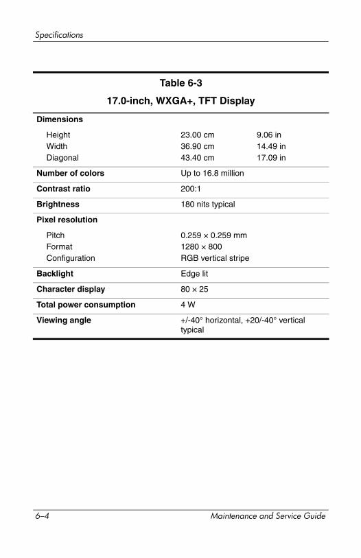
Specifications
Table 6-3
17.0-inch, WXGA+, TFT Display
Dimensions
HeightWidthDiagonal
23.00 cm36.90 cm43.40 cm
9.06 in14.49 in17.09 in
Number of colors Up to 16.8 million
Contrast ratio 200:1
Brightness 180 nits typical
Pixel resolution
PitchFormatConfiguration
0.259 × 0.259 mm1280 × 800RGB vertical stripe
Backlight Edge lit
Character display 80 × 25
Total power consumption 4 W
Viewing angle +/-40° horizontal, +20/-40° vertical typical
6–4 Maintenance and Service Guide
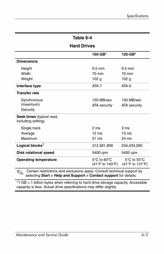
Specifications
Table 6-4
Hard Drives
160-GB* 120-GB*
Dimensions
HeightWidthWeight
9.5 mm70 mm102 g
9.5 mm70 mm102 g
Interface type ATA-7 ATA-5
Transfer rate
Synchronous (maximum)Security
150 MB/secATA security
100 MB/secATA security
Seek times (typical read, including setting)
Single trackAverageMaximum
2 ms12 ms21 ms
3 ms13 ms24 ms
Logical blocks† 312,581,808 234,433,260
Disk rotational speed 5400 rpm 5400 rpm
Operating temperature 5°C to 60°C (41°F to 140°F)
5°C to 55°C (41°F to 131°F)
✎ Certain restrictions and exclusions apply. Consult technical support by selecting Start > Help and Support > Contact support for details.
*1 GB = 1 billion bytes when referring to hard drive storage capacity. Accessible capacity is less. Actual drive specifications may differ slightly.
Maintenance and Service Guide 6–5
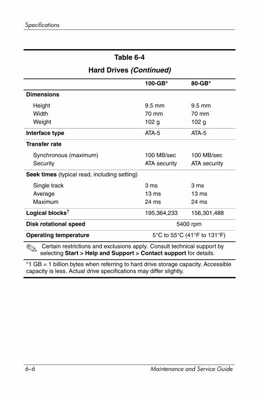
Specifications
100-GB* 80-GB*
Dimensions
HeightWidthWeight
9.5 mm70 mm102 g
9.5 mm70 mm102 g
Interface type ATA-5 ATA-5
Transfer rate
Synchronous (maximum)Security
100 MB/secATA security
100 MB/secATA security
Seek times (typical read, including setting)
Single trackAverageMaximum
3 ms13 ms24 ms
3 ms13 ms24 ms
Logical blocks† 195,364,233 156,301,488
Disk rotational speed 5400 rpm
Operating temperature 5°C to 55°C (41°F to 131°F)
✎ Certain restrictions and exclusions apply. Consult technical support by selecting Start > Help and Support > Contact support for details.
*1 GB = 1 billion bytes when referring to hard drive storage capacity. Accessible capacity is less. Actual drive specifications may differ slightly.
Table 6-4
Hard Drives (Continued)
6–6 Maintenance and Service Guide
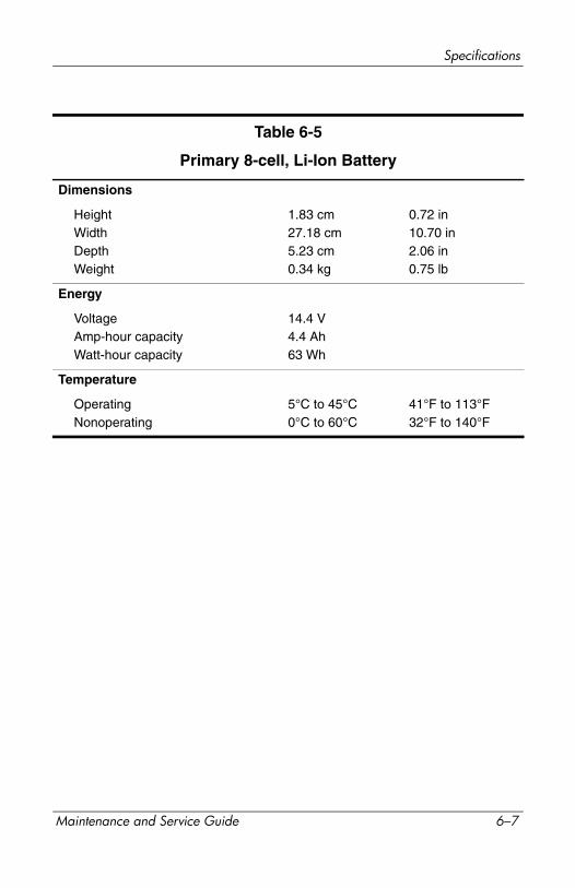
Specifications
Table 6-5
Primary 8-cell, Li-Ion Battery
Dimensions
HeightWidthDepthWeight
1.83 cm27.18 cm5.23 cm0.34 kg
0.72 in10.70 in2.06 in0.75 lb
Energy
VoltageAmp-hour capacityWatt-hour capacity
14.4 V4.4 Ah63 Wh
Temperature
OperatingNonoperating
5°C to 45°C0°C to 60°C
41°F to 113°F32°F to 140°F
Maintenance and Service Guide 6–7

Specifications
Table 6-6
DVD/CD-RW Combo Drive
Applicable disc Read:DVD-R, DVD-RW, DVD-ROM (DVD-5, DVD-9, DVD-10, DVD-18),CD-ROM (Mode 1 and 2)CD Digital AudioCD-XA ready (Mode 2, Form 1 and 2)CD-I ready (Mode 2, Form 1 and 2)CD-R, CD-RWPhoto CD (single and multisession)CD-Bridge
Write:CD-R and CD-RW
Access time CD media DVD media
Random < 110 ms < 130 ms
Cache buffer 2 MB
Data transfer rate
CD-R (24X)CD-RW (10X)CD-ROM (24X)DVD (8X)Multiword DMA mode 2
3600 KB/s (150 KB/s at 1X CD rate)1500 KB/s (150 KB/s at 1X CD rate)3600 KB/s (150 KB/s at 1X CD rate)10,800 KB/s (1352 KB/s at 1X DVD rate)16.6 MB/s
6–8 Maintenance and Service Guide
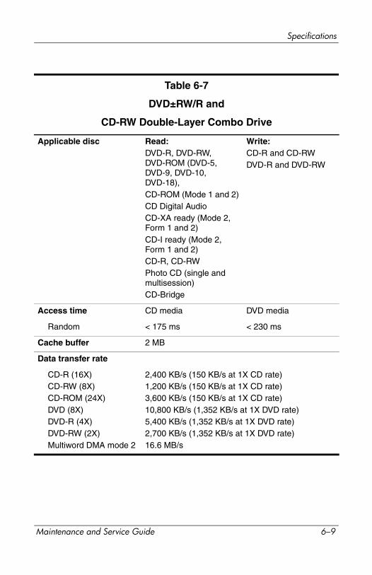
Specifications
Table 6-7
DVD±RW/R and
CD-RW Double-Layer Combo Drive
Applicable disc Read:DVD-R, DVD-RW, DVD-ROM (DVD-5, DVD-9, DVD-10, DVD-18),CD-ROM (Mode 1 and 2)CD Digital AudioCD-XA ready (Mode 2, Form 1 and 2)CD-I ready (Mode 2, Form 1 and 2)CD-R, CD-RWPhoto CD (single and multisession)CD-Bridge
Write:CD-R and CD-RWDVD-R and DVD-RW
Access time CD media DVD media
Random < 175 ms < 230 ms
Cache buffer 2 MB
Data transfer rate
CD-R (16X)CD-RW (8X)CD-ROM (24X)DVD (8X)DVD-R (4X)DVD-RW (2X)Multiword DMA mode 2
2,400 KB/s (150 KB/s at 1X CD rate)1,200 KB/s (150 KB/s at 1X CD rate)3,600 KB/s (150 KB/s at 1X CD rate)10,800 KB/s (1,352 KB/s at 1X DVD rate)5,400 KB/s (1,352 KB/s at 1X DVD rate)2,700 KB/s (1,352 KB/s at 1X DVD rate)16.6 MB/s
Maintenance and Service Guide 6–9
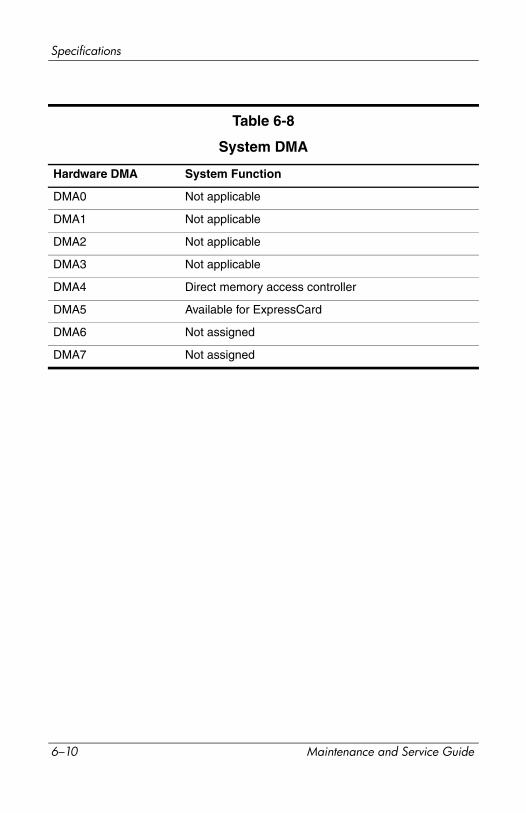
Specifications
Table 6-8
System DMA
Hardware DMA System Function
DMA0 Not applicable
DMA1 Not applicable
DMA2 Not applicable
DMA3 Not applicable
DMA4 Direct memory access controller
DMA5 Available for ExpressCard
DMA6 Not assigned
DMA7 Not assigned
6–10 Maintenance and Service Guide

Specifications
Table 6-9
System Interrupts
Hardware IRQ System Function
IRQ0 System timer
IRQ1 Quick Launch buttons
IRQ2 Cascaded
IRQ3 USB2 Enhanced Host Controller—24CD
IRQ4 COM1
IRQ5* Conexant AC—Link AudioSMBus Controller—24C3Data Fax Modem with SmartCP
IRQ6 Diskette drive
IRQ7* Parallel port
IRQ8 System CMOS/real-time clock
IRQ9* Microsoft ACPI-compliant system
IRQ10* USB UHCI controller—24C2GM/GME Graphic ControllerRealtek RTL8139 Family PCI fast Ethernet Controller
IRQ11 USB EHCI controller—24CDUSB UHCI controller—24C4USB UHCI controller—24C7Pro/Wireless 2200BGTI OHCI 1394 host controllerTI PCI1410 CardBus controller
*Default configuration
✎ ExpressCard may assert IRQ3, IRQ4, IRQ5, IRQ7, or IRQ20.
Maintenance and Service Guide 6–11

Specifications
Hardware IRQ System Function
IRQ12 Synaptics PS/2 port pointing device
IRQ13 Numeric data processor
IRQ14 Primary IDE channel
IRQ15 Secondary IDE channel
IRQ17 Conexant AC -Link Audio
IRQ17 Soft V90 Data Fax Modem with SmartCP
IRQ17 ATi Mobility Radeon Xpress 200 Series
IRQ19 Standard Enhanced PCI to USB Host Controller
IRQ19 Standard OpenHCD USB Host Controller
IRQ19 Standard OpenHCD USB Host Controller
IRQ20 TI 6411 PCIxx21/x515 Cardbus Controller
IRQ20 TI OHCI Compliant IEEE 1394 Host Controller
IRQ21 TI Integrated PCIxx21 FlashMedia Controller
IRQ21 Broadcom 802.11b/g WLAN
IRQ21 Microsoft ACPI-compliant system
IRQ22 Realtek RTL8100CL Family PCI fast Ethernet Controller
IRQ23 SDA Standard Compliant SD Host Controller
*Default configuration
✎ ExpressCard may assert IRQ3, IRQ4, IRQ5, IRQ7, or IRQ20.
Table 6-9
System Interrupts (Continued)
6–12 Maintenance and Service Guide

Specifications
Table 6-10
System I/O Addresses
I/O Address (hex) System Function (shipping configuration)
0x00000000-0x00000CF7 PCI bus
0x00000000-0x00000CF7 Direct memory access controller
0x00000020-0x00000021 Programmable interrupt controller
0x0000002E-0x0000002F System board resources
0x00000040-0x00000043 System timer
0x00000060-0x00000060 Quick Launch Buttons
0x00000061-0x00000061 System speaker
0x00000062-0x00000062 Microsoft ACPI-Compliant Embedded Controller
0x00000064-0x00000064 Quick Launch Buttons
0x00000066-0x00000066 Microsoft ACPI-Compliant Embedded Controller
0x00000070-0x00000071 System CMOS/real time clock
0x00000072-0x00000073 System board resources
0x00000080-0x0000008F Direct memory access controller
0x00000092-0x00000092 System board resources
0x000000A0-0x000000A1 Programmable interrupt controller
0x000000B0-0x000000B1 System board resources
0x000000C0-0x000000DF Direct memory access controller
0x000000F0-0x000000FE Numeric data processor
0x00000170-0x00000177 Secondary IDE Channel
Maintenance and Service Guide 6–13
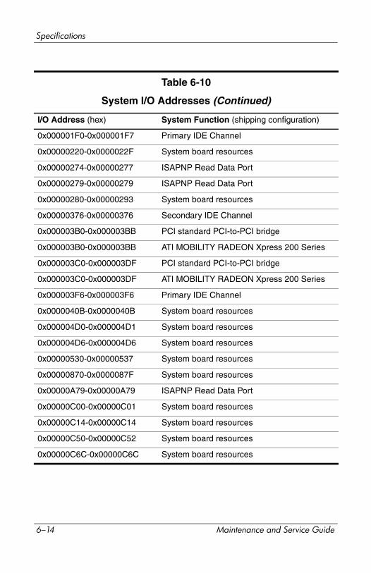
Specifications
I/O Address (hex) System Function (shipping configuration)
0x000001F0-0x000001F7 Primary IDE Channel
0x00000220-0x0000022F System board resources
0x00000274-0x00000277 ISAPNP Read Data Port
0x00000279-0x00000279 ISAPNP Read Data Port
0x00000280-0x00000293 System board resources
0x00000376-0x00000376 Secondary IDE Channel
0x000003B0-0x000003BB PCI standard PCI-to-PCI bridge
0x000003B0-0x000003BB ATI MOBILITY RADEON Xpress 200 Series
0x000003C0-0x000003DF PCI standard PCI-to-PCI bridge
0x000003C0-0x000003DF ATI MOBILITY RADEON Xpress 200 Series
0x000003F6-0x000003F6 Primary IDE Channel
0x0000040B-0x0000040B System board resources
0x000004D0-0x000004D1 System board resources
0x000004D6-0x000004D6 System board resources
0x00000530-0x00000537 System board resources
0x00000870-0x0000087F System board resources
0x00000A79-0x00000A79 ISAPNP Read Data Port
0x00000C00-0x00000C01 System board resources
0x00000C14-0x00000C14 System board resources
0x00000C50-0x00000C52 System board resources
0x00000C6C-0x00000C6C System board resources
Table 6-10
System I/O Addresses (Continued)
6–14 Maintenance and Service Guide
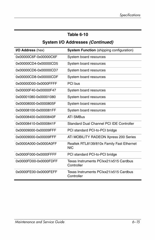
Specifications
I/O Address (hex) System Function (shipping configuration)
0x00000C6F-0x00000C6F System board resources
0x00000CD4-0x00000CD5 System board resources
0x00000CD6-0x00000CD7 System board resources
0x00000CD8-0x00000CDF System board resources
0x00000D00-0x0000FFFF PCI bus
0x00000F40-0x00000F47 System board resources
0x00001080-0x00001080 System board resources
0x00008000-0x0000805F System board resources
0x00008100-0x000081FF System board resources
0x00008400-0x0000840F ATI SMBus
0x00008410-0x0000841F Standard Dual Channel PCI IDE Controller
0x00009000-0x00009FFF PCI standard PCI-to-PCI bridge
0x00009000-0x00009FFF ATI MOBILITY RADEON Xpress 200 Series
0x0000A000-0x0000A0FF Realtek RTL8139/810x Family Fast Ethernet NIC
0x0000F000-0x0000FFFF PCI standard PCI-to-PCI bridge
0x0000FD00-0x0000FDFF Texas Instruments PCIxx21/x515 Cardbus Controller
0x0000FE00-0x0000FEFF Texas Instruments PCIxx21/x515 Cardbus Controller
Table 6-10
System I/O Addresses (Continued)
Maintenance and Service Guide 6–15
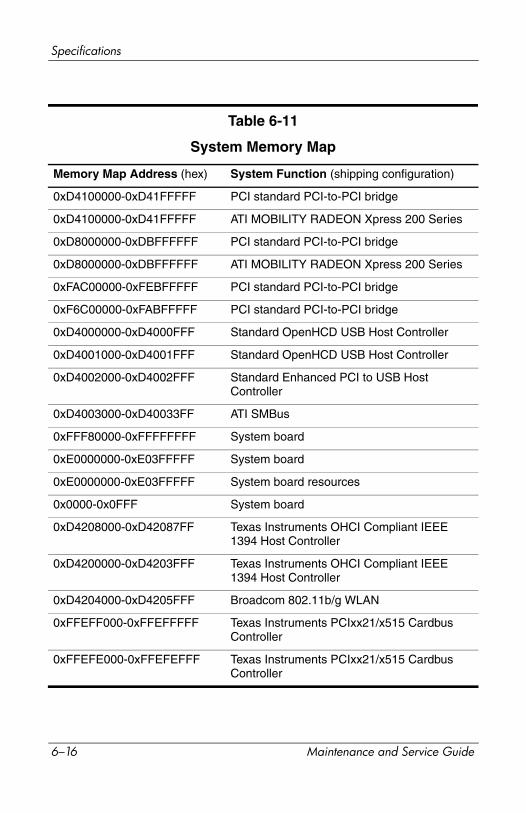
Specifications
Table 6-11
System Memory Map
Memory Map Address (hex) System Function (shipping configuration)
0xD4100000-0xD41FFFFF PCI standard PCI-to-PCI bridge
0xD4100000-0xD41FFFFF ATI MOBILITY RADEON Xpress 200 Series
0xD8000000-0xDBFFFFFF PCI standard PCI-to-PCI bridge
0xD8000000-0xDBFFFFFF ATI MOBILITY RADEON Xpress 200 Series
0xFAC00000-0xFEBFFFFF PCI standard PCI-to-PCI bridge
0xF6C00000-0xFABFFFFF PCI standard PCI-to-PCI bridge
0xD4000000-0xD4000FFF Standard OpenHCD USB Host Controller
0xD4001000-0xD4001FFF Standard OpenHCD USB Host Controller
0xD4002000-0xD4002FFF Standard Enhanced PCI to USB Host Controller
0xD4003000-0xD40033FF ATI SMBus
0xFFF80000-0xFFFFFFFF System board
0xE0000000-0xE03FFFFF System board
0xE0000000-0xE03FFFFF System board resources
0x0000-0x0FFF System board
0xD4208000-0xD42087FF Texas Instruments OHCI Compliant IEEE 1394 Host Controller
0xD4200000-0xD4203FFF Texas Instruments OHCI Compliant IEEE 1394 Host Controller
0xD4204000-0xD4205FFF Broadcom 802.11b/g WLAN
0xFFEFF000-0xFFEFFFFF Texas Instruments PCIxx21/x515 Cardbus Controller
0xFFEFE000-0xFFEFEFFF Texas Instruments PCIxx21/x515 Cardbus Controller
6–16 Maintenance and Service Guide
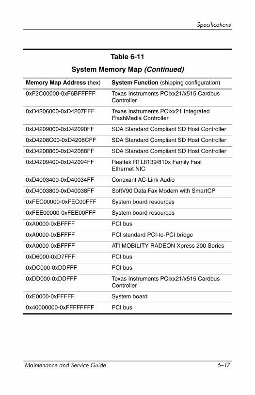
Specifications
Memory Map Address (hex) System Function (shipping configuration)
0xF2C00000-0xF6BFFFFF Texas Instruments PCIxx21/x515 Cardbus Controller
0xD4206000-0xD4207FFF Texas Instruments PCIxx21 Integrated FlashMedia Controller
0xD4209000-0xD42090FF SDA Standard Compliant SD Host Controller
0xD4208C00-0xD4208CFF SDA Standard Compliant SD Host Controller
0xD4208800-0xD42088FF SDA Standard Compliant SD Host Controller
0xD4209400-0xD42094FF Realtek RTL8139/810x Family Fast Ethernet NIC
0xD4003400-0xD40034FF Conexant AC-Link Audio
0xD4003800-0xD40038FF SoftV90 Data Fax Modem with SmartCP
0xFEC00000-0xFEC00FFF System board resources
0xFEE00000-0xFEE00FFF System board resources
0xA0000-0xBFFFF PCI bus
0xA0000-0xBFFFF PCI standard PCI-to-PCI bridge
0xA0000-0xBFFFF ATI MOBILITY RADEON Xpress 200 Series
0xD6000-0xD7FFF PCI bus
0xDC000-0xDDFFF PCI bus
0xDD000-0xDDFFF Texas Instruments PCIxx21/x515 Cardbus Controller
0xE0000-0xFFFFF System board
0x40000000-0xFFFFFFFF PCI bus
Table 6-11
System Memory Map (Continued)
Maintenance and Service Guide 6–17
Specifications
6–18 Maintenance and Service Guide
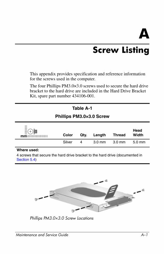
AScrew Listing
This appendix provides specification and reference information for the screws used in the computer.
The four Phillips PM3.0×3.0 screws used to secure the hard drive bracket to the hard drive are included in the Hard Drive Bracket Kit, spare part number 434106-001.
Phillips PM3.0×3.0 Screw Locations
Table A-1
Phillips PM3.0×3.0 Screw
Color Qty. Length ThreadHead Width
Silver 4 3.0 mm 3.0 mm 5.0 mm
Where used:4 screws that secure the hard drive bracket to the hard drive (documented in Section 5.4)
mm
Maintenance and Service Guide A–1
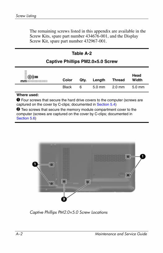
Screw Listing
The remaining screws listed in this appendix are available in the Screw Kits, spare part number 434676-001, and the Display Screw Kit, spare part number 432967-001.
Captive Phillips PM2.0×5.0 Screw Locations
Table A-2
Captive Phillips PM2.0×5.0 Screw
Color Qty. Length ThreadHead Width
Black 6 5.0 mm 2.0 mm 5.0 mm
Where used:1 Four screws that secure the hard drive covers to the computer (screws are captured on the cover by C-clips; documented in Section 5.4)2 Two screws that secure the memory module compartment cover to the computer (screws are captured on the cover by C-clips; documented inSection 5.6)
mm
A–2 Maintenance and Service Guide
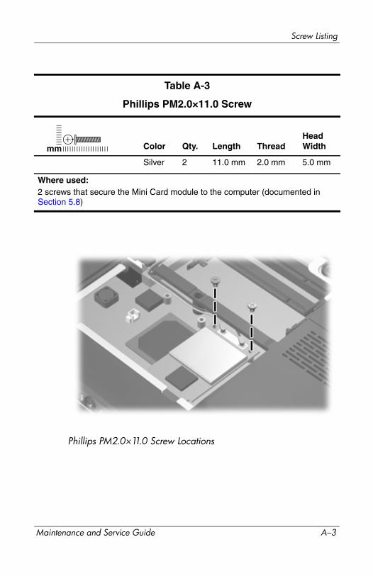
Screw Listing
Phillips PM2.0×11.0 Screw Locations
Table A-3
Phillips PM2.0×11.0 Screw
Color Qty. Length ThreadHead Width
Silver 2 11.0 mm 2.0 mm 5.0 mm
Where used:2 screws that secure the Mini Card module to the computer (documented in Section 5.8)
mm
Maintenance and Service Guide A–3
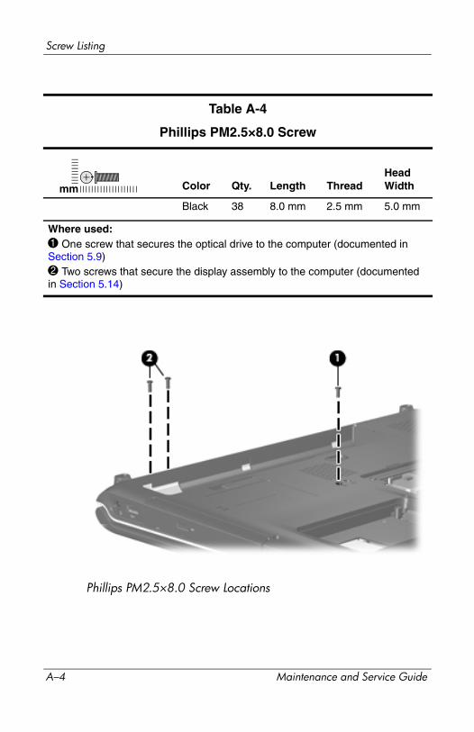
Screw Listing
Phillips PM2.5×8.0 Screw Locations
Table A-4
Phillips PM2.5×8.0 Screw
Color Qty. Length ThreadHead Width
Black 38 8.0 mm 2.5 mm 5.0 mm
Where used:1 One screw that secures the optical drive to the computer (documented inSection 5.9)2 Two screws that secure the display assembly to the computer (documented in Section 5.14)
mm
A–4 Maintenance and Service Guide
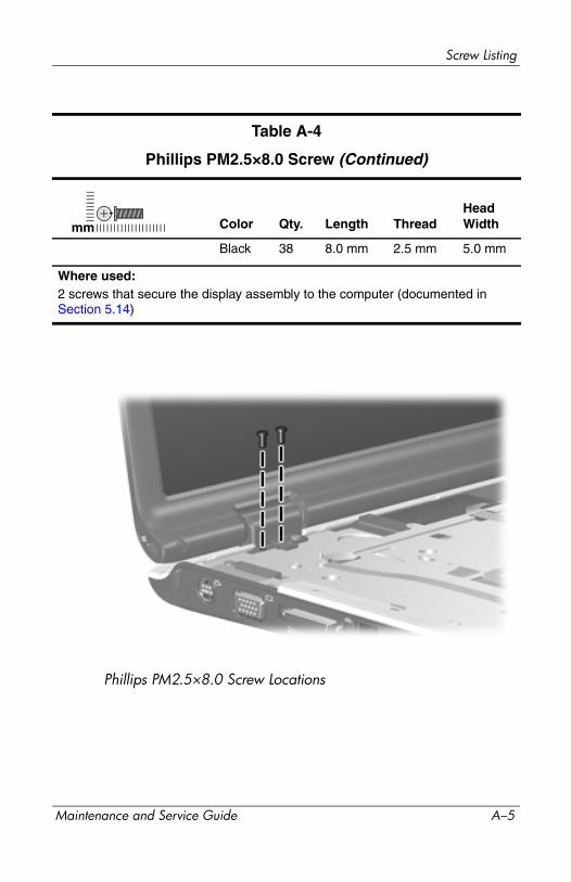
Screw Listing
Phillips PM2.5×8.0 Screw Locations
Table A-4
Phillips PM2.5×8.0 Screw (Continued)
Color Qty. Length ThreadHead Width
Black 38 8.0 mm 2.5 mm 5.0 mm
Where used:2 screws that secure the display assembly to the computer (documented in Section 5.14)
mm
Maintenance and Service Guide A–5

Screw Listing
Phillips PM2.5×8.0 Screw Locations
Table A-4
Phillips PM2.5×8.0 Screw (Continued)
Color Qty. Length ThreadHead Width
Black 38 8.0 mm 2.5 mm 5.0 mm
Where used:5 screws that secure the display bezel to the display enclosure (documented in Section 5.14)
mm
A–6 Maintenance and Service Guide

Screw Listing
Phillips PM2.5×8.0 Screw Locations
Table A-4
Phillips PM2.5×8.0 Screw (Continued)
Color Qty. Length ThreadHead Width
Black 38 8.0 mm 2.5 mm 5.0 mm
Where used:6 screws that secure the display panel to the display enclosure (documented in Section 5.14)
mm
Maintenance and Service Guide A–7
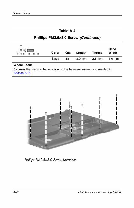
Screw Listing
Phillips PM2.5×8.0 Screw Locations
Table A-4
Phillips PM2.5×8.0 Screw (Continued)
Color Qty. Length ThreadHead Width
Black 38 8.0 mm 2.5 mm 5.0 mm
Where used:8 screws that secure the top cover to the base enclosure (documented inSection 5.15)
mm
A–8 Maintenance and Service Guide
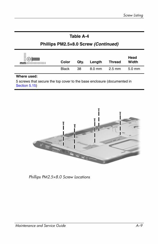
Screw Listing
Phillips PM2.5×8.0 Screw Locations
Table A-4
Phillips PM2.5×8.0 Screw (Continued)
Color Qty. Length ThreadHead Width
Black 38 8.0 mm 2.5 mm 5.0 mm
Where used:5 screws that secure the top cover to the base enclosure (documented inSection 5.15)
mm
Maintenance and Service Guide A–9
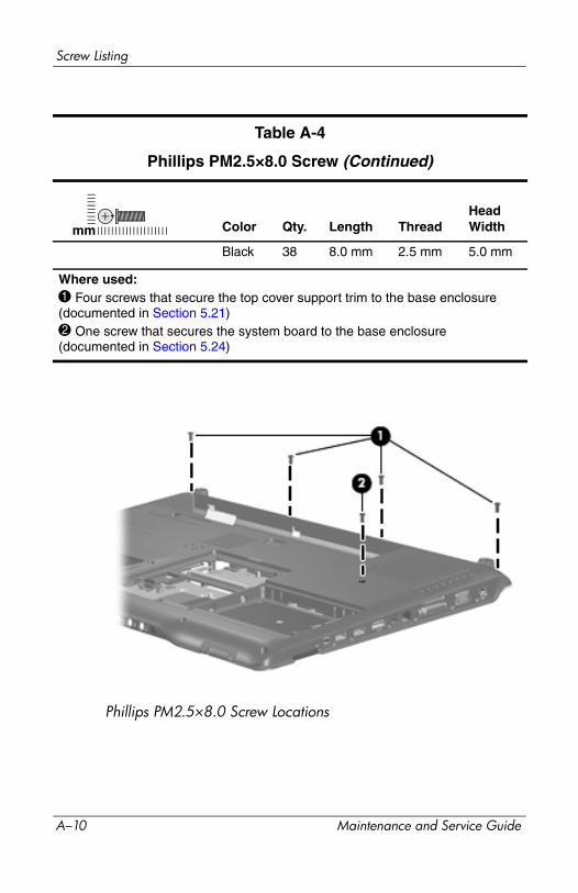
Screw Listing
Phillips PM2.5×8.0 Screw Locations
Table A-4
Phillips PM2.5×8.0 Screw (Continued)
Color Qty. Length ThreadHead Width
Black 38 8.0 mm 2.5 mm 5.0 mm
Where used:1 Four screws that secure the top cover support trim to the base enclosure (documented in Section 5.21)2 One screw that secures the system board to the base enclosure (documented in Section 5.24)
mm
A–10 Maintenance and Service Guide
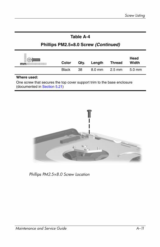
Screw Listing
Phillips PM2.5×8.0 Screw Location
Table A-4
Phillips PM2.5×8.0 Screw (Continued)
Color Qty. Length ThreadHead Width
Black 38 8.0 mm 2.5 mm 5.0 mm
Where used:One screw that secures the top cover support trim to the base enclosure (documented in Section 5.21)
mm
Maintenance and Service Guide A–11
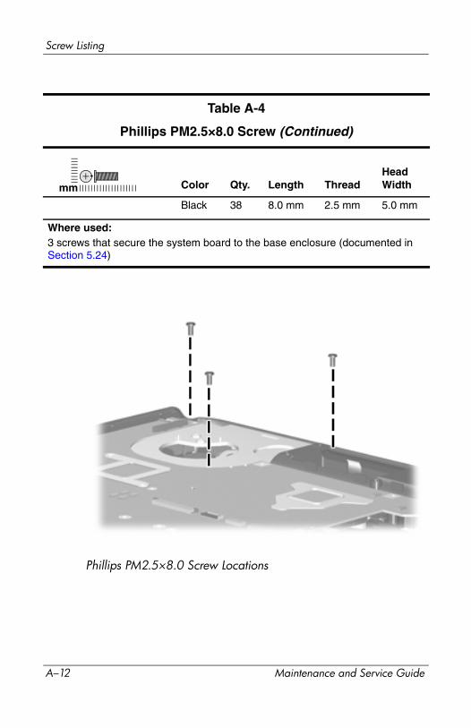
Screw Listing
Phillips PM2.5×8.0 Screw Locations
Table A-4
Phillips PM2.5×8.0 Screw (Continued)
Color Qty. Length ThreadHead Width
Black 38 8.0 mm 2.5 mm 5.0 mm
Where used:3 screws that secure the system board to the base enclosure (documented in Section 5.24)
mm
A–12 Maintenance and Service Guide
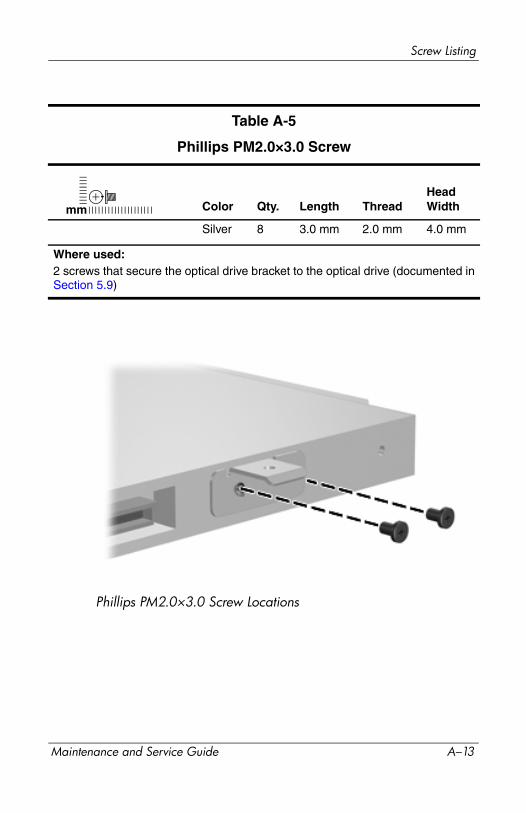
Screw Listing
Phillips PM2.0×3.0 Screw Locations
Table A-5
Phillips PM2.0×3.0 Screw
Color Qty. Length ThreadHead Width
Silver 8 3.0 mm 2.0 mm 4.0 mm
Where used:2 screws that secure the optical drive bracket to the optical drive (documented inSection 5.9)
mm
Maintenance and Service Guide A–13
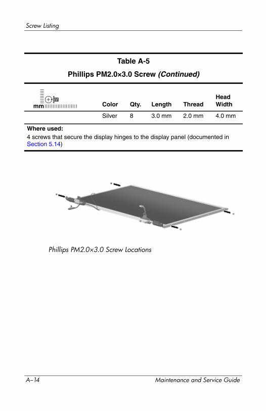
Screw Listing
Phillips PM2.0×3.0 Screw Locations
Table A-5
Phillips PM2.0×3.0 Screw (Continued)
Color Qty. Length ThreadHead Width
Silver 8 3.0 mm 2.0 mm 4.0 mm
Where used:4 screws that secure the display hinges to the display panel (documented inSection 5.14)
mm
A–14 Maintenance and Service Guide

Screw Listing
Phillips PM2.0×3.0 Screw Locations
Table A-5
Phillips PM2.0×3.0 Screw (Continued)
Color Qty. Length ThreadHead Width
Silver 8 3.0 mm 2.0 mm 4.0 mm
Where used:2 screws that secure the Bluetooth module to the base enclosure (documented in Section 5.18)
mm
Maintenance and Service Guide A–15

Screw Listing
Phillips PM2.0×5.0 Screw Locations
Table A-6
Phillips PM2.0×5.0 Screw
Color Qty. Length ThreadHead Width
Silver 6 5.0 mm 2.0 mm 5.0 mm
Where used:6 screws that secure the switch cover to the computer (documented inSection 5.10)
mm
A–16 Maintenance and Service Guide
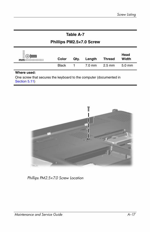
Screw Listing
Phillips PM2.5×7.0 Screw Location
Table A-7
Phillips PM2.5×7.0 Screw
Color Qty. Length ThreadHead Width
Black 1 7.0 mm 2.5 mm 5.0 mm
Where used:One screw that secures the keyboard to the computer (documented inSection 5.11)
mm
Maintenance and Service Guide A–17
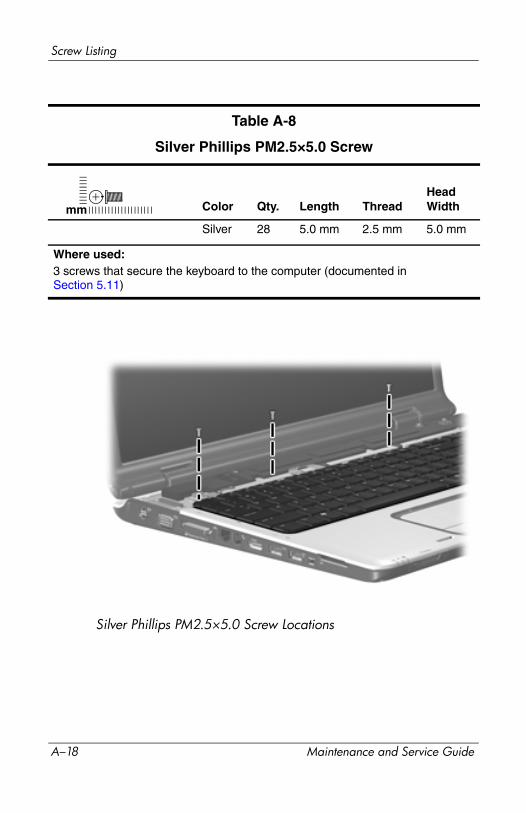
Screw Listing
Silver Phillips PM2.5×5.0 Screw Locations
Table A-8
Silver Phillips PM2.5×5.0 Screw
Color Qty. Length ThreadHead Width
Silver 28 5.0 mm 2.5 mm 5.0 mm
Where used:3 screws that secure the keyboard to the computer (documented inSection 5.11)
mm
A–18 Maintenance and Service Guide
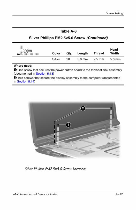
Screw Listing
Silver Phillips PM2.5×5.0 Screw Locations
Table A-8
Silver Phillips PM2.5×5.0 Screw (Continued)
Color Qty. Length ThreadHead Width
Silver 28 5.0 mm 2.5 mm 5.0 mm
Where used:1 One screw that secures the power button board to the fan/heat sink assembly (documented in Section 5.13)2 Two screws that secure the display assembly to the computer (documented in Section 5.14)
mm
Maintenance and Service Guide A–19

Screw Listing
Silver Phillips PM2.5×5.0 Screw Locations
Table A-8
Silver Phillips PM2.5×5.0 Screw (Continued)
Color Qty. Length ThreadHead Width
Silver 28 5.0 mm 2.5 mm 5.0 mm
Where used:4 screws that secure the top cover to the base enclosure (documented in Section 5.15)
mm
A–20 Maintenance and Service Guide
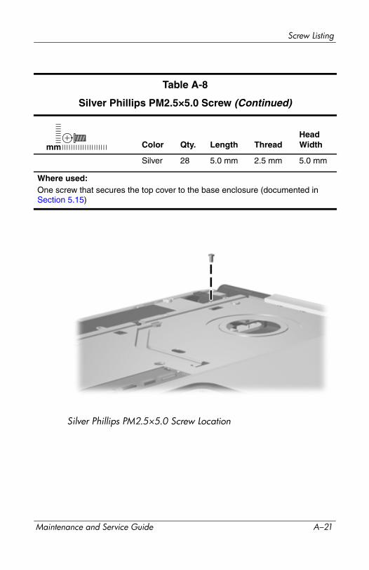
Screw Listing
Silver Phillips PM2.5×5.0 Screw Location
Table A-8
Silver Phillips PM2.5×5.0 Screw (Continued)
Color Qty. Length ThreadHead Width
Silver 28 5.0 mm 2.5 mm 5.0 mm
Where used:One screw that secures the top cover to the base enclosure (documented in Section 5.15)
mm
Maintenance and Service Guide A–21
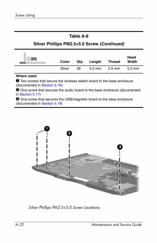
Screw Listing
Silver Phillips PM2.5×5.0 Screw Locations
Table A-8
Silver Phillips PM2.5×5.0 Screw (Continued)
Color Qty. Length ThreadHead Width
Silver 28 5.0 mm 2.5 mm 5.0 mm
Where used:1 Two screws that secure the wireless switch board to the base enclosure (documented in Section 5.16)2 One screw that secures the audio board to the base enclosure (documented in Section 5.17)3 One screw that secures the USB/magnetic board to the base enclosure (documented in Section 5.19)
mm
A–22 Maintenance and Service Guide
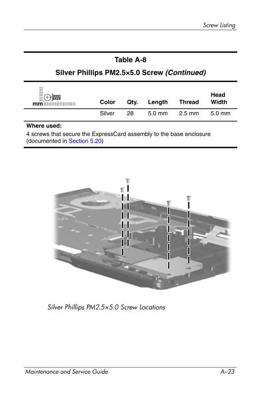
Screw Listing
Silver Phillips PM2.5×5.0 Screw Locations
Table A-8
Silver Phillips PM2.5×5.0 Screw (Continued)
Color Qty. Length ThreadHead Width
Silver 28 5.0 mm 2.5 mm 5.0 mm
Where used:4 screws that secure the ExpressCard assembly to the base enclosure (documented in Section 5.20)
mm
Maintenance and Service Guide A–23

Screw Listing
Silver Phillips PM2.5×5.0 Screw Locations
Table A-8
Silver Phillips PM2.5×5.0 Screw (Continued)
Color Qty. Length ThreadHead Width
Silver 28 5.0 mm 2.5 mm 5.0 mm
Where used:1 Two screws that secure the power connector assembly bracket to the base enclosure (documented in Section 5.23)2 One screw that secures the USB board to the base enclosure (documented in Section 5.23)
mm
A–24 Maintenance and Service Guide
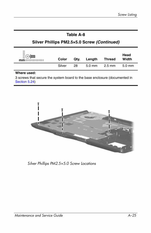
Screw Listing
Silver Phillips PM2.5×5.0 Screw Locations
Table A-8
Silver Phillips PM2.5×5.0 Screw (Continued)
Color Qty. Length ThreadHead Width
Silver 28 5.0 mm 2.5 mm 5.0 mm
Where used:3 screws that secure the system board to the base enclosure (documented in Section 5.24)
mm
Maintenance and Service Guide A–25

Screw Listing
Silver Phillips PM2.5×5.0 Screw Locations
Table A-8
Silver Phillips PM2.5×5.0 Screw (Continued)
Color Qty. Length ThreadHead Width
Silver 28 5.0 mm 2.5 mm 5.0 mm
Where used:3 screws that secure the heat sink to the system board (documented inSection 5.25)
mm
A–26 Maintenance and Service Guide
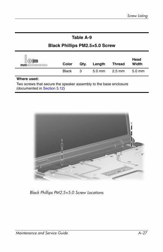
Screw Listing
Black Phillips PM2.5×5.0 Screw Locations
Table A-9
Black Phillips PM2.5×5.0 Screw
Color Qty. Length ThreadHead Width
Black 3 5.0 mm 2.5 mm 5.0 mm
Where used:Two screws that secure the speaker assembly to the base enclosure (documented in Section 5.12)
mm
Maintenance and Service Guide A–27
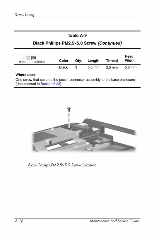
Screw Listing
Black Phillips PM2.5×5.0 Screw Location
Table A-9
Black Phillips PM2.5×5.0 Screw (Continued)
Color Qty. Length ThreadHead Width
Black 3 5.0 mm 2.5 mm 5.0 mm
Where used:One screw that secures the power connector assembly to the base enclosure (documented in Section 5.23)
mm
A–28 Maintenance and Service Guide
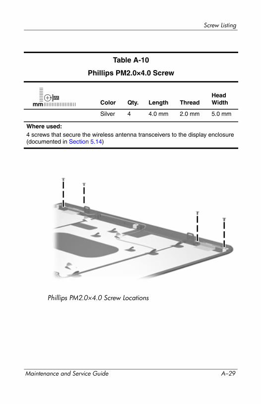
Screw Listing
Phillips PM2.0×4.0 Screw Locations
Table A-10
Phillips PM2.0×4.0 Screw
Color Qty. Length ThreadHead Width
Silver 4 4.0 mm 2.0 mm 5.0 mm
Where used:4 screws that secure the wireless antenna transceivers to the display enclosure (documented in Section 5.14)
mm
Maintenance and Service Guide A–29

Screw Listing
Phillips PM2.5×6.0 Screw Locations
Table A-11
Phillips PM2.5×6.0 Screw
Color Qty. Length ThreadHead Width
Black 4 6.0 mm 2.5 mm 5.0 mm
Where used:4 screws that secure the fan/heat sink assembly to the system board (documented in Section 5.25)
mm
A–30 Maintenance and Service Guide
BBackup and Recovery
Backup and Recovery in Windows XP
Recovering System InformationTools provided by the operating system and PC Recovery software are designed to help you with the following tasks for safeguarding your information and restoring it in case of a system failure:
■ Backing up your information regularly to protect your important system files.
■ Making a set of recovery discs (PC Recovery software feature). Recovery discs are used to start up (boot) your computer and restore the operating system and software programs to factory settings in case of system failure or instability.
■ Creating system restore points (operating system feature). System restore points allow you to reverse undesirable changes to your computer by restoring the computer to an earlier state.
■ Recovering a program or driver (PC Recovery software feature). This feature helps you reinstall a program or driver without performing a full system recovery.
■ Performing a full system recovery (PC Recovery software feature). With PC Recovery, you can recover your full factory image if you experience system failure or instability. PC Recovery works from a dedicated recovery partition on the hard drive or from recovery discs you create.
Maintenance and Service Guide B–1
Backup and Recovery
Backing Up Your Information
When to Back Up■ On a regularly scheduled basis
✎ Set reminders to back up your information periodically.
■ Before the computer is repaired or restored
■ Before you add or modify hardware or software
Backup Suggestions■ Create system restore points using Windows XP Professional
System Restore feature.
■ Store personal files in the My Documents folder and back up these folders periodically.
■ Back up templates stored in their associated programs.
■ Save customized settings in a window, toolbar, or menu bar by taking a screen shot of your settings.
The screen shot can be a time saver if you have to reset your preferences.
To copy the screen and paste it into a Word document:
a. Display the screen.
b. Copy the screen:
To copy only the active window, press alt+fn+prt sc.
To copy the entire screen, press fn+prt sc.
c. To paste the copied images into a document, open Word, and then select Edit > Paste.
B–2 Maintenance and Service Guide

Backup and Recovery
Using System Restore PointsWhen you back up your system, you are creating a system restore point. A system restore point allows you to save and name a snapshot of your hard drive at a specific point in time. You can then recover back to that point if you want to reverse subsequent changes made to your system.
✎ Recovering to an earlier restore point does not affect data files saved or e-mails created since the last restore point.
You also can create additional restore points to provide increased protection for your system files and settings.
When to Create Restore Points■ Before you add or extensively modify software or hardware.
■ Periodically, whenever the system is performing optimally.
✎ If you revert to a restore point and then change your mind, you can reverse the restoration.
Creating a System Restore Point1. Select Start > Help and Support > System Restore.
The System Restore window opens.
2. Click Create a restore point, and then click Next.
3. Follow the on-screen instructions.
Restoring to a Previous Date and TimeTo revert to a restore point (created at a previous date and time), when the computer was functioning optimally:
1. Select Start > Help and Support > System Restore.
The System Restore window opens.
Maintenance and Service Guide B–3
Backup and Recovery
2. Click Restore my computer to an earlier time, and then click Next.
3. Follow the on-screen instructions.
Creating Recovery DiscsPC Recovery Disc Creator creates a set of recovery CDs or DVDs for the computer. Use recovery discs to restore the operating system and software programs to factory settings, in case of system failure or instability.
✎ Handle these discs carefully and keep them in a safe place. The software allows the creation of only one set of recovery discs.
Note the following guidelines before creating recovery discs:
■ You will need high quality CD-R, DVD-R, or DVD+R media (purchased separately).
✎ DVD±RW/R and double-layer DVD±RW are not compatible with the PC Recovery Disc Creator software.
■ The computer must be connected to AC power during this process.
■ Only one set of recovery discs can be created per computer.
■ Number each disc before inserting it into the computer optical drive.
■ If necessary, you can exit the program before you have finished creating the recovery discs. The next time you open PC Recovery Disc Creator, you will be prompted to continue the disc creation process.
To create a set of recovery discs:
1. Select Start > All Programs > System Recovery > PC Recovery Disc Creator.
The PC Recovery Disc Creator tool opens.
2. Click Next.
B–4 Maintenance and Service Guide
Backup and Recovery
✎ If you are operating the computer on battery power, you will be prompted to connect to AC power before you can go to the next step.
3. Select the type of disc you want to use and click Next.
✎ The software examines the image and displays the number of blank discs needed to create your recovery discs.
4. Insert the first disc and follow the on-screen instructions to complete the creation of the recovery discs.
Reinstalling Software Programs and DriversIf a program or driver preinstalled at the factory is accidentally erased or is damaged, the Application and Driver Recovery tool allows you to reinstall it.
✎ Software not provided with this computer must be reinstalled from the disc provided by the manufacturer or downloaded from the manufacturer's Web site.
✎ Before reinstalling the program, be sure it is fully uninstalled.
The Application and Driver Recovery tool replaces corrupted system files and reinstalls deleted system files within the program.
■ In most cases, if the program you are reinstalling is still on your computer, the reinstallation process does not affect your personal settings.
■ In all cases, if a program has been deleted from your computer, the reinstallation process reinstalls the program or utility to the factory image but cannot restore your personal settings.
Maintenance and Service Guide B–5
Backup and Recovery
Reinstalling Preinstalled Programs and Drivers1. Remove the program or driver:
✎ In some cases, drivers are not listed in the Add or Remove Programs list. If the driver is not listed, it does not need to be removed.
a. Select Start > Control Panel > Add or Remove Programs.
b. Click the program or driver you want to remove, and then click Change/Remove.
2. Select Start > All Programs > System Recovery > Application and Driver Recovery.
The Application and Driver Recovery tool opens.
3. Select Application Installation or Driver Installation, and then click Next.
4. Follow the on-screen instructions to complete the program or driver recovery.
5. Restart the computer if prompted.
Reinstalling Programs from Discs1. Insert the disc into the optical drive.
2. When the installation wizard opens, follow the installation instructions on the screen.
3. Restart the computer if prompted.
Performing a RecoveryPC Recovery software allows you to repair or restore the system if you experience system failure or instability. PC Recovery works from recovery discs that you create or from a dedicated recovery partition on the hard drive.
B–6 Maintenance and Service Guide
Backup and Recovery
✎ Microsoft Windows XP has its own built-in repair features, such as System Restore and driver roll-back capabilities. If you have not already tried these features, try them before using PC Recovery.
✎ PC Recovery only recovers software that was preinstalled at the factory. Software not provided with this computer must be reinstalled from the disc provided by the manufacturer or downloaded from the manufacturer's Web site.
Recovering from the Recovery DiscsTo restore the system from the recovery discs:
1. Back up all personal files.
2. Insert the first recovery disc into the optical drive and restart the computer.
3. Follow the on-screen instructions.
Recovering from the Partition on the Hard DriveYou can perform a recovery from the partition on the hard drive from either the Start button or f11.
To restore the system from the partition:
1. Access the PC Recovery tool:
❏ To access PC Recovery from the Start button, select Start > All Programs > System Recovery > PC Recovery.
❏ To access PC Recovery from f11, restart the computer and press f11 while the “Press <F11> for recovery” message is displayed on the screen.
The PC Recovery tool opens.
2. Select PC Recovery and click Next.
The computer restarts and the PC Recovery tool opens.
Maintenance and Service Guide B–7
Backup and Recovery
3. Click OK.
4. Follow the on-screen instructions to complete the system recovery.
If you want to perform a destructive recovery:
✎ A destructive recovery formats the hard drive and restores the computer to its factory state. Select this option only as a last resort.
a. Click Advanced Options on the System Recovery screen.
b. Select Destructive Recovery and follow the on-screen instructions.
Deleting the Recovery Partition on the Hard DriveThe PC Recovery Advanced Options menu provides the option of deleting the recovery partition, which will increase space on the hard drive. Delete the recovery partition only if you have already created recovery discs.
ÄCAUTION: After you create the recovery discs, you can increase space on the hard drive by deleting the recovery partition. However, doing this is not recommended. If you delete this partition, you will lose any information that is on the partition, including the PC Recovery software. Thereafter, you must use the recovery discs to access PC Recovery software.
To delete the recovery partition:
1. If you have not already created recovery discs, create them now.
2. Select Start > All Programs > System Recovery > PC Recovery.
The PC Recovery tool opens.
3. Select PC Recovery and click Next.
The computer restarts and the PC Recovery tools opens.
B–8 Maintenance and Service Guide

Backup and Recovery
4. Click OK.
5. At the System Recovery screen, click Advanced Options.
6. Select Delete Recovery Partition (not recommended) and follow the on-screen instructions.
Updating Reinstalled SoftwareAfter you perform a system recovery, connect to the Internet to update all reinstalled software.
To access update links for the operating system and other software provided on your computer:
» Select Start > Help and Support.
To update optional software, follow the instructions provided by the software manufacturer. Some programs include an update feature you can access from a Help button or menu within the program.
Backup and Recovery in Windows Vista
Recovering System InformationTools provided by the operating system and Recovery Manager software are designed to help you with the following tasks for safeguarding your information and restoring it in case of a system failure:
■ Back up your information regularly to protect your important system files.
■ Make a set of recovery discs (Recovery Manager software feature). Recovery discs are used to start up (boot) your computer and restore the operating system and software programs to factory settings in case of system failure or instability.
Maintenance and Service Guide B–9
Backup and Recovery
■ Create system restore points (operating system feature). System restore points allow you to reverse undesirable changes to your computer by restoring the computer to an earlier state.
■ Recover a program or driver (Recovery Manager software feature). This feature helps you reinstall a program or driver without performing a full system recovery.
■ Perform a full system recovery (Recovery Manager software feature). With Recovery Manager, you can recover your full factory image if you experience system failure or instability. Recovery Manager works from a dedicated recovery partition on the hard drive or from recovery discs you create.
Backing up Your Information
When to Back Up■ On a regularly scheduled basis.
✎ Set reminders to back up your information periodically.
■ Before the computer is repaired or restored.
■ Before you add or modify hardware or software.
Backup Suggestions■ Create system restore points using the Windows System
Restore feature.
■ Store personal files in the Documents folder and back up these folders periodically.
■ Back up templates stored in their associated programs.
■ Save customized settings in a window, toolbar, or menu bar by taking a screen shot of your settings.
The screen shot can be a time saver if you have to reset your preferences.
B–10 Maintenance and Service Guide
Backup and Recovery
To copy the screen and paste it into a word-processing document:
a. Display the screen.
b. Copy the screen:
To copy only the active window, press alt+fn+prt sc.
To copy the entire screen, press fn+prt sc.
c. Open a word-processing document, and then select Edit > Paste.
Using System Restore PointsWhen you back up your system, you are creating a system restore point. A system restore point allows you to save and name a snapshot of your hard drive at a specific point in time. You can then recover back to that point if you want to reverse subsequent changes made to your system.
✎ Recovering to an earlier restore point does not affect data files saved or e-mails created since the last restore point.
You also can create additional restore points to provide increased protection for your system files and settings.
When to Create Restore Points■ Before you add or extensively modify software or hardware.
■ Periodically, whenever the system is performing optimally.
✎ If you revert to a restore point and then change your mind, you can reverse the restoration.
Creating a System Restore Point1. Select Start > Control Panel > System and Maintenance >
System.
2. In the left pane, click System protection.
Maintenance and Service Guide B–11

Backup and Recovery
3. Click the System Protection tab.
4. Under Automatic restore points, select the disk for which you want to create a restore point.
5. Click Create.
The System Protection window opens.
6. Follow the on-screen instructions.
Restoring to a Previous Date and TimeTo revert to a restore point (created at a previous date and time), when the computer was functioning optimally, follow these steps:
1. Select Start > Control Panel > System and Maintenance > System.
2. In the left pane, click System protection.
3. Click the System Protection tab.
4. Click the System Restore button, and then click Next.
The System Restore window opens.
5. Follow the on-screen instructions.
Creating Recovery DiscsRecovery Manager creates a set of recovery CDs or DVDs for the computer. Use recovery discs to restore the operating system and software programs to factory settings, in case of system failure or instability.
✎ Handle these discs carefully and keep them in a safe place. The software allows the creation of only one set of recovery discs.
Note the following guidelines before creating recovery discs:
■ You will need high quality CD-R, DVD-R, or DVD+R discs (purchased separately).
B–12 Maintenance and Service Guide
Backup and Recovery
✎ Formatted DVD±RW discs and DVD±RW double-layer discs are not compatible with the Recovery Manager software.
■ The computer must be connected to AC power during this process.
■ Only one set of recovery discs can be created per computer.
■ Number each disc before inserting it into the computer optical drive.
■ If necessary, you can exit the program before you have finished creating the recovery discs. The next time you open Recovery Manager, you will be prompted to continue the disc creation process.
To create a set of recovery discs:
1. Select Start > All Programs > Recovery Manager > Recovery Manager.
Recovery Manager opens.
2. Click Advanced Options.
✎ If you are operating the computer on battery power, you will be prompted to connect to AC power before you can go to the next step.
3. Click Recovery disc creation, and then click Next.
4. Follow the on-screen instructions.
Reinstalling Software Programs and DriversIf a program or driver preinstalled at the factory is accidentally erased or is damaged, Recovery Manager allows you to reinstall it.
✎ Software not provided with this computer must be reinstalled from the disc provided by the manufacturer or downloaded from the manufacturer's Web site.
Maintenance and Service Guide B–13
Backup and Recovery
✎ Before reinstalling the program, be sure it is fully uninstalled.
Recovery Manager replaces corrupted system files and reinstalls deleted system files within the program.
■ In most cases, if the program you are reinstalling is still on your computer, the reinstallation process does not affect your personal settings.
■ In all cases, if a program has been deleted from your computer, the reinstallation process reinstalls the program or utility to the factory image but cannot restore your personal settings.
Reinstalling Preinstalled Programs and Drivers1. Remove the program or driver:
✎ Before reinstalling the program, be sure it is fully uninstalled.
a. Select Start > Control Panel > Programs > Uninstall a program.
b. Right-click the program or driver you want to remove, and then click Uninstall.
2. Reinstall the program or driver:
a. Select Start > All Programs > Recovery Manager > Recovery Manager.
Recovery Manager opens.
b. Click Advanced Options.
c. Click either Software program re-installation or Hardware driver re-installation, and then click Next.
d. Follow the on-screen instructions.
e. Restart the computer if prompted.
Reinstalling Programs from Discs1. Insert the disc into the optical drive.
B–14 Maintenance and Service Guide
Backup and Recovery
2. When the installation wizard opens, follow the installation instructions on the screen.
3. Restart the computer if prompted.
Performing a RecoveryRecovery Manager software allows you to repair or restore the system if you experience system failure or instability. Recovery Manager works from recovery discs that you create or from a dedicated recovery partition on the hard drive.
✎ Windows has its own built-in repair features, such as System Restore and driver rollback capabilities. If you have not already tried these features, try them before using Recovery Manager.
✎ Recovery Manager only recovers software that was preinstalled at the factory. Software not provided with this computer must be reinstalled from the disc provided by the manufacturer or downloaded from the manufacturer's Web site.
Recovering from the Recovery DiscsTo restore the system from the recovery discs:
1. Back up all personal files.
2. Insert the first recovery disc into the optical drive and restart the computer.
3. Follow the on-screen instructions.
Recovering from the Partition on the Hard DriveYou can perform a recovery from the partition on the hard drive from either the Start button or f11.
To restore the system from the partition, follow these steps:
1. Access Recovery Manager in either of the following ways:
Maintenance and Service Guide B–15

Backup and Recovery
❏ Select Start > All Programs > Recovery Manager > Recovery Manager.
❏ Restart the computer and press f11 while the “Press <F11> for recovery” message is displayed on the screen. Then select Recovery Manager.
Recovery Manager opens.
2. Click Advanced Options.
3. Click System recovery, and then click Next.
4. Follow the on-screen instructions.
Deleting the Recovery Partition on the Hard DriveThe Recovery Manager Advanced Options menu provides the option of deleting the recovery partition, which will increase space on the hard drive. Delete the recovery partition only if you have already created recovery discs.
ÄCAUTION: After you create the recovery discs, you can increase space on the hard drive by deleting the recovery partition. However, doing this is not recommended. If you delete this partition, you will lose any information that is on the partition, including Recovery Manager software. Thereafter, you must use the recovery discs to access Recovery Manager software.
To delete the recovery partition:
1. If you have not already created recovery discs, create them now.
2. Select Start > All Programs > Recovery Manager > Recovery Manager.
Recovery Manager opens.
3. Click Advanced Options.
4. Click Remove recovery partition, and then click Next.
5. Follow the on-screen instructions.
B–16 Maintenance and Service Guide
Backup and Recovery
Updating Reinstalled SoftwareAfter you perform a system recovery, connect to the Internet to update all reinstalled software.
To access update links for the operating system and other software provided on your computer:
» Select Start > Help and Support.
To update optional software, follow the instructions provided by the software manufacturer. Some programs include an update feature you can access from a Help button or menu within the program.
Maintenance and Service Guide B–17
Backup and Recovery
B–18 Maintenance and Service Guide
CDisplay Component Recycling
ÅWARNING: The backlight contains mercury. Caution should be exercised when removing and handling the backlight to avoid damaging this component and causing exposure to the mercury.
ÄCAUTION: The procedures in this appendix can result in damage to display components. The only components intended for recycling purposes are the liquid crystal display (LCD) panel and the backlight. Careful handling should be exercised when removing these components.
✎ Materials DisposalThis HP product contains mercury in the display assembly backlight and may require special handling at end-of-life.
Disposal of mercury may be regulated because of environmental considerations. For disposal or recycling information, contact your local authorities or visit the Electronic Industries Alliance (EIA) at http://www.eiae.org.
Maintenance and Service Guide C–1
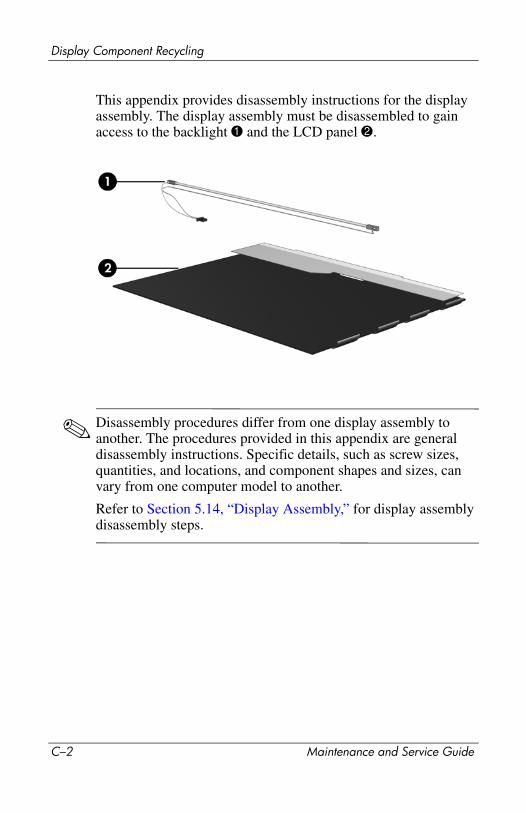
Display Component Recycling
This appendix provides disassembly instructions for the display assembly. The display assembly must be disassembled to gain access to the backlight 1 and the LCD panel 2.
✎ Disassembly procedures differ from one display assembly to another. The procedures provided in this appendix are general disassembly instructions. Specific details, such as screw sizes, quantities, and locations, and component shapes and sizes, can vary from one computer model to another.
Refer to Section 5.14, “Display Assembly,” for display assembly disassembly steps.
C–2 Maintenance and Service Guide

Display Component Recycling
Perform the following steps to disassemble the display assembly:
1. Remove all screw covers 1 and screws 2 that secure the display bezel to the display assembly.
Removing the Display Bezel Screw Covers and Screws
Maintenance and Service Guide C–3
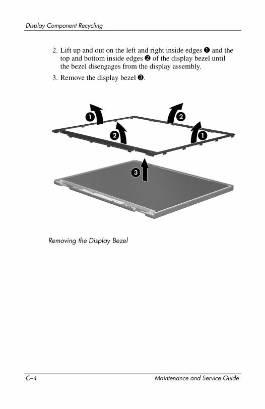
Display Component Recycling
2. Lift up and out on the left and right inside edges 1 and the top and bottom inside edges 2 of the display bezel until the bezel disengages from the display assembly.
3. Remove the display bezel 3.
Removing the Display Bezel
C–4 Maintenance and Service Guide
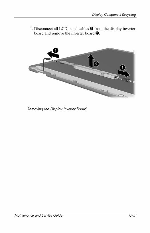
Display Component Recycling
4. Disconnect all LCD panel cables 1 from the display inverter board and remove the inverter board 2.
Removing the Display Inverter Board
Maintenance and Service Guide C–5
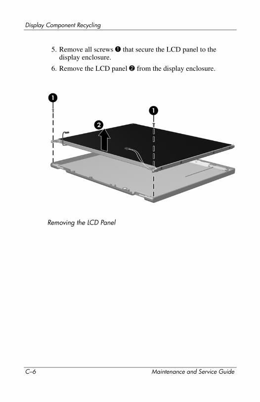
Display Component Recycling
5. Remove all screws 1 that secure the LCD panel to the display enclosure.
6. Remove the LCD panel 2 from the display enclosure.
Removing the LCD Panel
C–6 Maintenance and Service Guide
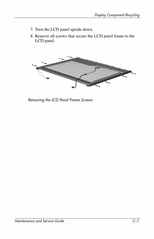
Display Component Recycling
7. Turn the LCD panel upside down.
8. Remove all screws that secure the LCD panel frame to the LCD panel.
Removing the LCD Panel Frame Screws
Maintenance and Service Guide C–7
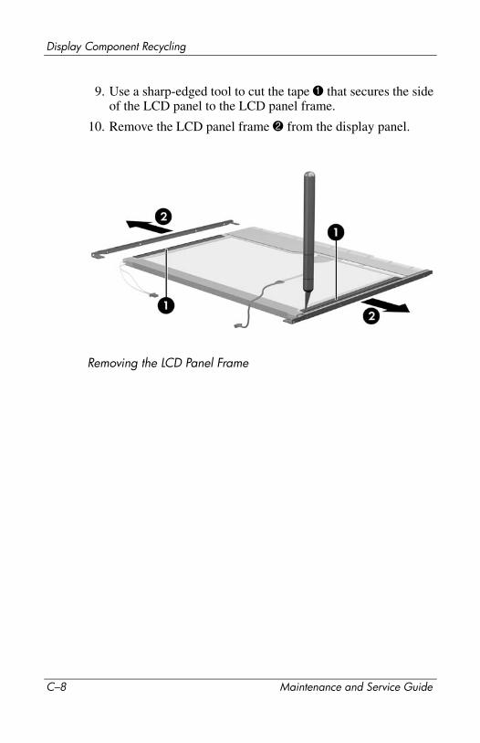
Display Component Recycling
9. Use a sharp-edged tool to cut the tape 1 that secures the side of the LCD panel to the LCD panel frame.
10. Remove the LCD panel frame 2 from the display panel.
Removing the LCD Panel Frame
C–8 Maintenance and Service Guide

Display Component Recycling
11. Remove the screws 1 that secure the backlight cover to the LCD panel.
12. Lift the top edge of the backlight cover 2 and swing it forward.
13. Remove the backlight cover.
Removing the Backlight Cover
Maintenance and Service Guide C–9
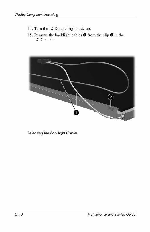
Display Component Recycling
14. Turn the LCD panel right-side up.
15. Remove the backlight cables 1 from the clip 2 in the LCD panel.
Releasing the Backlight Cables
C–10 Maintenance and Service Guide
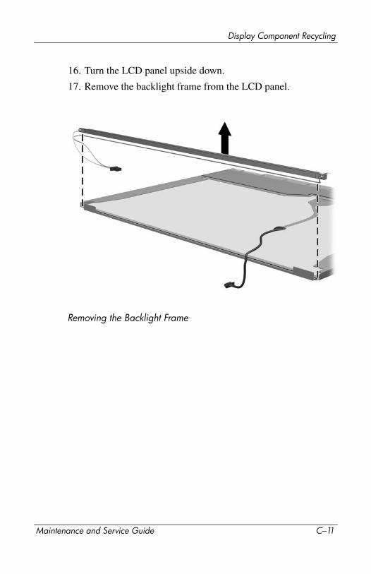
Display Component Recycling
16. Turn the LCD panel upside down.
17. Remove the backlight frame from the LCD panel.
Removing the Backlight Frame
Maintenance and Service Guide C–11
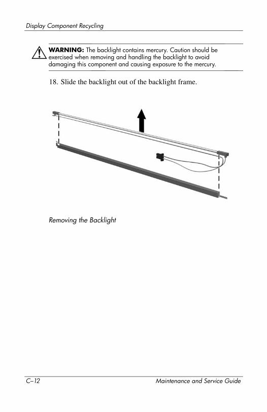
Display Component Recycling
ÅWARNING: The backlight contains mercury. Caution should be exercised when removing and handling the backlight to avoid damaging this component and causing exposure to the mercury.
18. Slide the backlight out of the backlight frame.
Removing the Backlight
C–12 Maintenance and Service Guide
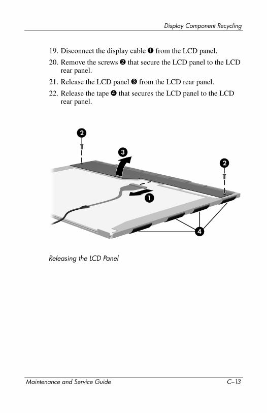
Display Component Recycling
19. Disconnect the display cable 1 from the LCD panel.
20. Remove the screws 2 that secure the LCD panel to the LCD rear panel.
21. Release the LCD panel 3 from the LCD rear panel.
22. Release the tape 4 that secures the LCD panel to the LCD rear panel.
Releasing the LCD Panel
Maintenance and Service Guide C–13
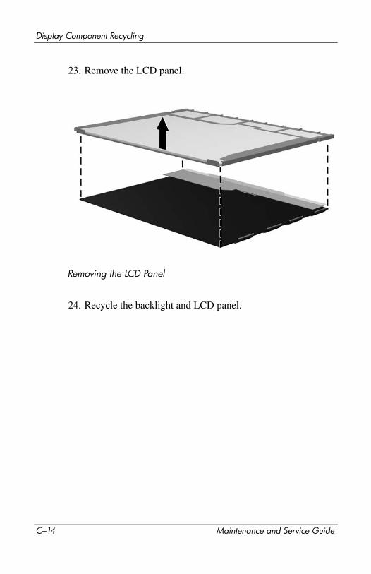
Display Component Recycling
23. Remove the LCD panel.
Removing the LCD Panel
24. Recycle the backlight and LCD panel.
C–14 Maintenance and Service Guide

DConnector Pin Assignments
Table E-1
Universal Serial Bus
Pin Signal Pin Signal
1 +5 VDC 3 Data +
2 Data – 4 Ground
Maintenance and Service Guide D–1

Connector Pin Assignments
Table E-2
RJ-45 (Network)
Pin Signal Pin Signal
1 Transmit + 5 Unused
2 Transmit – 6 Receive –
3 Receive + 7 Unused
4 Unused 8 Unused
D–2 Maintenance and Service Guide
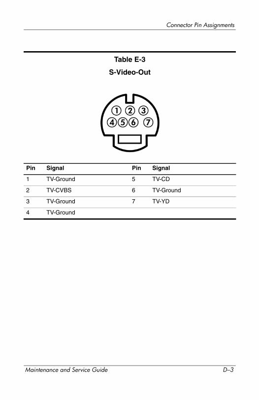
Connector Pin Assignments
Table E-3
S-Video-Out
Pin Signal Pin Signal
1 TV-Ground 5 TV-CD
2 TV-CVBS 6 TV-Ground
3 TV-Ground 7 TV-YD
4 TV-Ground
Maintenance and Service Guide D–3
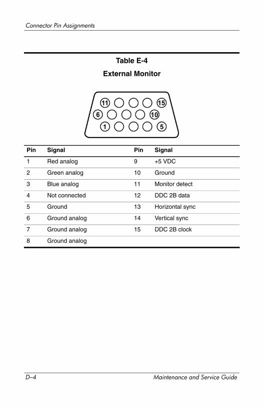
Connector Pin Assignments
Table E-4
External Monitor
Pin Signal Pin Signal
1 Red analog 9 +5 VDC
2 Green analog 10 Ground
3 Blue analog 11 Monitor detect
4 Not connected 12 DDC 2B data
5 Ground 13 Horizontal sync
6 Ground analog 14 Vertical sync
7 Ground analog 15 DDC 2B clock
8 Ground analog
D–4 Maintenance and Service Guide

Connector Pin Assignments
Table E-5
RJ-11 (Modem)
Pin Signal Pin Signal
1 Unused 4 Unused
2 Tip 5 Unused
3 Ring 6 Unused
Maintenance and Service Guide D–5
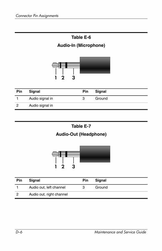
Connector Pin Assignments
Table E-6
Audio-In (Microphone)
Pin Signal Pin Signal
1 Audio signal in 3 Ground
2 Audio signal in
Table E-7
Audio-Out (Headphone)
Pin Signal Pin Signal
1 Audio out, left channel 3 Ground
2 Audio out, right channel
D–6 Maintenance and Service Guide
EPower Cord Set Requirements
3-Conductor Power Cord SetThe wide range input feature of the computer permits it to operate from any line voltage from 100 to 120 or 220 to 240 volts AC.
The power cord set included with the computer meets the requirements for use in the country or region where the equipment is purchased.
Power cord sets for use in other countries and regions must meet the requirements of the country or region where the computer is used.
Maintenance and Service Guide E–1
Power Cord Set Requirements
General RequirementsThe requirements listed below are applicable to all countries and regions.
■ The length of the power cord set must be at least 1.5 m (5.0 ft) and a maximum of 2.0 m (6.5 ft).
■ All power cord sets must be approved by an acceptable accredited agency responsible for evaluation in the country or region where the power cord set will be used.
■ The power cord sets must have a minimum current capacity of 10 amps and a nominal voltage rating of 125 or 250 V AC, as required by each country’s or region’s power system.
■ The appliance coupler must meet the mechanical configuration of an EN 60 320/IEC 320 Standard Sheet C13 connector for mating with the appliance inlet on the back of the computer.
E–2 Maintenance and Service Guide
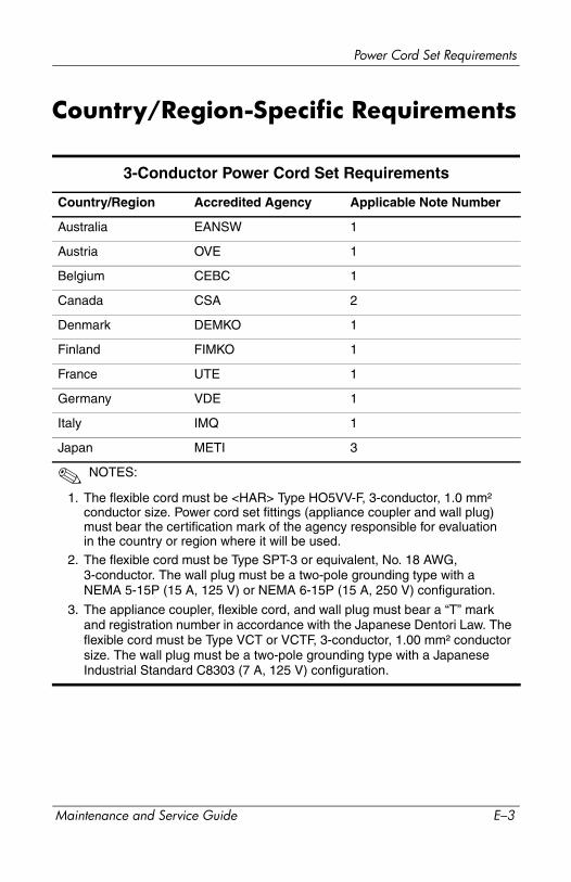
Power Cord Set Requirements
Country/Region-Specific Requirements
3-Conductor Power Cord Set Requirements
Country/Region Accredited Agency Applicable Note Number
Australia EANSW 1
Austria OVE 1
Belgium CEBC 1
Canada CSA 2
Denmark DEMKO 1
Finland FIMKO 1
France UTE 1
Germany VDE 1
Italy IMQ 1
Japan METI 3
✎ NOTES:
1. The flexible cord must be <HAR> Type HO5VV-F, 3-conductor, 1.0 mm²
conductor size. Power cord set fittings (appliance coupler and wall plug) must bear the certification mark of the agency responsible for evaluation in the country or region where it will be used.
2. The flexible cord must be Type SPT-3 or equivalent, No. 18 AWG, 3-conductor. The wall plug must be a two-pole grounding type with a NEMA 5-15P (15 A, 125 V) or NEMA 6-15P (15 A, 250 V) configuration.
3. The appliance coupler, flexible cord, and wall plug must bear a “T” mark and registration number in accordance with the Japanese Dentori Law. The flexible cord must be Type VCT or VCTF, 3-conductor, 1.00 mm² conductor size. The wall plug must be a two-pole grounding type with a Japanese Industrial Standard C8303 (7 A, 125 V) configuration.
Maintenance and Service Guide E–3
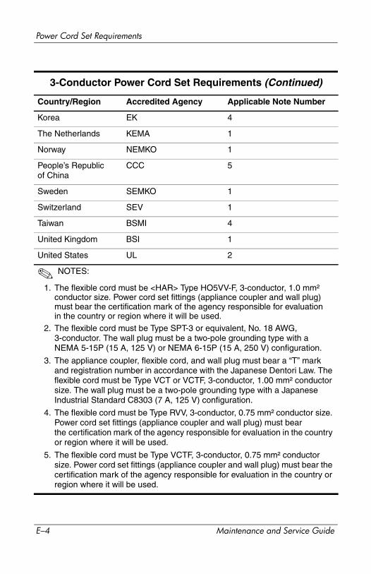
Power Cord Set Requirements
Korea EK 4
The Netherlands KEMA 1
Norway NEMKO 1
People’s Republic of China
CCC 5
Sweden SEMKO 1
Switzerland SEV 1
Taiwan BSMI 4
United Kingdom BSI 1
United States UL 2
✎ NOTES:
1. The flexible cord must be <HAR> Type HO5VV-F, 3-conductor, 1.0 mm²
conductor size. Power cord set fittings (appliance coupler and wall plug) must bear the certification mark of the agency responsible for evaluation in the country or region where it will be used.
2. The flexible cord must be Type SPT-3 or equivalent, No. 18 AWG, 3-conductor. The wall plug must be a two-pole grounding type with a NEMA 5-15P (15 A, 125 V) or NEMA 6-15P (15 A, 250 V) configuration.
3. The appliance coupler, flexible cord, and wall plug must bear a “T” mark and registration number in accordance with the Japanese Dentori Law. The flexible cord must be Type VCT or VCTF, 3-conductor, 1.00 mm² conductor size. The wall plug must be a two-pole grounding type with a Japanese Industrial Standard C8303 (7 A, 125 V) configuration.
4. The flexible cord must be Type RVV, 3-conductor, 0.75 mm² conductor size. Power cord set fittings (appliance coupler and wall plug) must bear the certification mark of the agency responsible for evaluation in the country or region where it will be used.
5. The flexible cord must be Type VCTF, 3-conductor, 0.75 mm² conductor size. Power cord set fittings (appliance coupler and wall plug) must bear the certification mark of the agency responsible for evaluation in the country or region where it will be used.
3-Conductor Power Cord Set Requirements (Continued)
Country/Region Accredited Agency Applicable Note Number
E–4 Maintenance and Service Guide
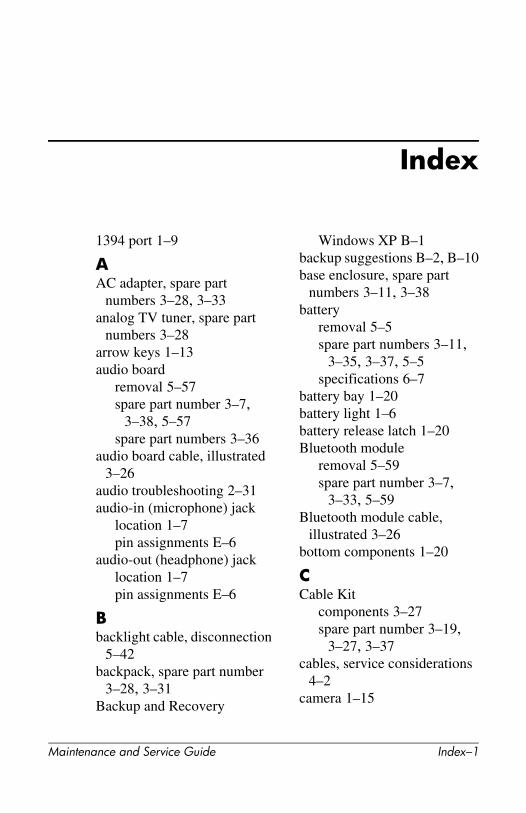
Index
1394 port 1–9
AAC adapter, spare part
numbers 3–28, 3–33analog TV tuner, spare part
numbers 3–28arrow keys 1–13audio board
removal 5–57spare part number 3–7,
3–38, 5–57spare part numbers 3–36
audio board cable, illustrated 3–26
audio troubleshooting 2–31audio-in (microphone) jack
location 1–7pin assignments E–6
audio-out (headphone) jacklocation 1–7pin assignments E–6
Bbacklight cable, disconnection
5–42backpack, spare part number
3–28, 3–31Backup and Recovery
Windows XP B–1backup suggestions B–2, B–10base enclosure, spare part
numbers 3–11, 3–38battery
removal 5–5spare part numbers 3–11,
3–35, 3–37, 5–5specifications 6–7
battery bay 1–20battery light 1–6battery release latch 1–20Bluetooth module
removal 5–59spare part number 3–7,
3–33, 5–59Bluetooth module cable,
illustrated 3–26bottom components 1–20
CCable Kit
components 3–27spare part number 3–19,
3–27, 3–37cables, service considerations
4–2camera 1–15
Maintenance and Service Guide Index–1
Index
camera cabledisconnection 5–37removal 5–47spare part number 3–21,
3–35, 5–47camera module
removal 5–41spare part number 3–21,
3–35, 5–41caps lock key 1–13caps lock light 1–15CMOS clearing 1–4components
bottom 1–20front 1–6keyboard 1–12left-side 1–8rear 1–8right-side 1–10top 1–14, 1–16, 1–19
composite S-Video and audio input cable, spare part number 3–28, 3–33
computer feet, locations 5–11Computer Setup
Advanced Menu 2–7, 2–14File Menu 2–5, 2–12Security Menu 2–6, 2–12Tools Menu 2–6, 2–12
computer specifications 6–1connector pin assignments
external monitor E–4headphone E–6microphone E–6monitor E–4RJ-11 (modem) E–5
RJ-45 (network) E–2S-Video-out E–3Universal Serial Bus (USB)
E–1connectors, service
considerations 4–2consumer infrared lens 1–7creating
recovery discsWindows Vista B–12Windows XP B–4
system restore pointWindows Vista B–11Windows XP B–3
Ddeleting
recovery partitionWindows Vista B–16Windows XP B–8
design overview 1–22Digital Media Slot 1–9Digital Media Slot light 1–9disassembly sequence chart
5–2diskette drive, OS loading
problems 2–29display assembly
removal 5–35spare part numbers 3–3,
3–33, 3–34, 5–35specifications 6–3, 6–4
display bezelremoval 5–40spare part numbers 3–20,
3–34, 3–37, 3–38, 5–40
Index–2 Maintenance and Service Guide
Index
Display Cable Kit, spare part number 3–21, 3–35, 5–47
display enclosure, spare part numbers 3–21, 3–34
display hingeremoval 5–44spare part numbers 5–44
display hinge coverremoval 5–44spare part number 3–21,
3–35, 5–44Display Hinge Kit, spare part
numbers 3–21, 3–35, 5–44display lid latch 1–7display lid switch module
removal 5–69spare part number 3–5,
3–36, 5–69display lid switch module
cabledisconnection 5–33illustrated 3–26
display panelremoval 5–43spare part numbers 3–21,
3–34, 5–43Display Screw Kit, spare part
number 3–21, 3–35docking device,
troubleshooting 2–24drive light 1–7drives, preventing damage 4–3DVB-T TV tuner antenna,
spare part number 3–28, 3–33
DVB-T TV tuner, spare part number 3–28, 3–33
DVD button 1–17DVD/CD-RW Combo Drive
OS loading problems 2–30precautions 4–3removal 5–19spare part numbers 3–19,
3–23, 3–37, 5–19specifications 6–8
DVD±RW/R and CD-RW Combo Drive
OS loading problems 2–30precautions 4–3removal 5–19spare part numbers 3–19,
3–23, 3–35, 5–19specifications 6–9
Eelectrostatic discharge 4–4,
4–8expansion port 3 1–9ExpressCard assembly
removal 5–63spare part number 3–9,
3–36, 5–63ExpressCard slot 1–11ExpressCard slot bezel
illustrated 3–25removal 5–64
external monitor portlocation 1–8pin assignments E–4
Ffan/heat sink assembly
Maintenance and Service Guide Index–3
Index
removal 5–80spare part numbers 3–9,
3–37, 5–80features 1–2feet, locations 5–11flowcharts, troubleshooting
no audio 2–31, 2–32no network/modem
connection 2–36no OS loading 2–25no OS loading from
diskette drive 2–29no OS loading from hard
drive 2–26, 2–27, 2–28no OS loading from optical
drive 2–30no power 2–18, 2–20, 2–21no video 2–22, 2–23nonfunctioning device
2–33nonfunctioning docking
device 2–24nonfunctioning keyboard
2–34nonfunctioning pointing
device 2–35fn key 1–13front components 1–6function keys 1–13
Ggrounding equipment and
methods 4–7
Hhard drive
OS loading problems 2–26
precautions 4–3removal 5–7spare part numbers 3–11,
3–22, 3–23, 3–36, 3–37, 5–7
specifications 6–5hard drive bay 1–21Hard Drive Bracket Kit, spare
part number 3–11, 3–23, 3–36, 5–7
hard drive bracket railsspare part numbers 3–38
hard drive bracket, removal 5–10
hard drive connectorspare part numbers 3–38
hard drive coverillustrated 3–25removal 5–8
hard drive screwsspare part numbers 3–38
HDMI port 1–9headphone jack
location 1–7pin assignments E–6
headset, spare part number 3–28, 3–31
heatsink, spare part numbers 3–38
hingeremoval 5–44spare part numbers 3–21,
3–35, 5–44hinge cover
removal 5–44
Index–4 Maintenance and Service Guide
Index
spare part number 3–21, 3–35, 5–44
II/O address specifications
6–13infrared receiver, spare part
numbers 3–28, 3–38interrupt specifications 6–11inverter
removal 5–42spare part numbers 3–21,
3–33, 3–35, 5–42
Kkeyboard
removal 5–26spare part numbers 3–5,
3–39, 3–40, 5–26troubleshooting 2–34
keyboard components 1–12keypad keys 1–13
LLED board cable,
disconnection 5–25left-side components 1–8logo kit, spare part numbers
3–28, 3–36
Mmass storage devices, spare
part numbers 3–22media button 1–17memory module
removal 5–12spare part numbers 3–17,
3–35, 3–37, 3–41, 5–12
memory module compartment 1–21
memory module compartment cover
illustrated 3–25removal 5–13
microphonelocation 1–15removal 5–46spare part number 3–21,
3–35, 5–46microphone cable,
disconnection 5–33microphone jack
location 1–7pin assignments E–6
Mini Card moduleremoval 5–16spare part numbers 3–13,
3–15, 3–17, 3–32, 3–33, 3–39, 5–16, 5–17
modem jacklocation 1–9pin assignments E–5
modem, troubleshooting 2–36monitor port
location 1–8pin assignments E–4
mouse, spare part number 3–28, 3–37, 3–38
Nnetwork jack
location 1–9pin assignments E–2
network, troubleshooting 2–36
Maintenance and Service Guide Index–5

Index
next/fast forward button 1–18nonfunctioning device,
troubleshooting 2–24, 2–33num lock key 1–13num lock light 1–15
Ooptical drive
location 1–11, 1–21OS loading problems 2–30precautions 4–3removal 5–19spare part numbers 3–19,
3–23, 5–19specifications 6–8
optical drive bracket, removal 5–20
optical drive connector boardremoval 5–78spare part number 3–9,
3–36, 5–78
Ppacking precautions 4–5password clearing 1–4performing a recovery
Windows Vista B–15Windows XP B–6
plastic parts 4–2Plastics Kit
contents 3–25spare part number 3–5,
3–25, 3–35play/pause button 1–18pointing device,
troubleshooting 2–35power button 1–15
power button boardremoval 5–33spare part number 3–3,
3–36, 5–33power connector 1–11power connector assembly
removal 5–71spare part number 3–9,
3–36, 5–71power connector assembly
cable, disconnection 5–79
power cordset requirements F–2spare part numbers 3–29,
3–31power light 1–6power management features
1–5power, troubleshooting 2–18previous/rewind button 1–18processor
removal 5–85spare part numbers 3–9,
3–33, 3–37, 3–38, 3–39, 5–85
Rrear components 1–8recovering from partition on
hard driveWindows Vista B–15Windows XP B–7
recovering from the recovery discs
Windows Vista B–15
Index–6 Maintenance and Service Guide
Index
Windows XP B–7remote control, spare part
number 3–28, 3–31remote control, spare part
numbers 3–28, 3–37, 3–38, 3–39
removalpreliminaries 4–1procedures 5–1
replacementpreliminaries 4–1procedures 5–1
RF input adapter cable, spare part number 3–28, 3–33
right-side components 1–10RJ-11 (modem) jack
location 1–9pin assignments E–5
RJ-45 (network) jacklocation 1–9pin assignments E–2
RTC batteryremoval 5–15spare part number 3–11,
3–33, 5–15
Sscrew kit
spare part numbers 3–36Screw Kit, spare part numbers
3–30, 3–37screw listing A–1security cable slot 1–8serial number 3–1, 5–2service considerations 4–2Setup Utility 2–1
speaker assemblyremoval 5–31spare part number 3–3,
3–36, 5–31speaker assembly cable,
disconnection 5–33speakers 1–15specifications
battery 6–7computer 6–1display 6–3, 6–4DVD/CD-RW Combo
Drive 6–8DVD±RW/R and CD-RW
Combo Drive 6–9hard drive 6–5I/O addresses 6–13interrupts 6–11optical drive 6–8system DMA 6–10
static shielding materials 4–8stop button 1–18S-Video and audio input cable,
spare part numbers 3–28S-Video-out jack
location 1–8pin assignments E–3
switch coverremoval 5–22spare part number 3–3,
3–35, 3–38, 3–40, 5–22system board
removal 5–75spare part number 3–40spare part numbers 3–7,
3–36, 3–37, 5–75
Maintenance and Service Guide Index–7

Index
system DMA 6–10
Tthermal pad, locations 5–82,
5–84thermal paste, locations 5–82,
5–84tools required 4–1top components 1–14, 1–16,
1–19top cover
removal 5–48spare part number 3–5,
3–40, 5–48top cover support trim
removal 5–66spare part number 3–5,
3–35, 5–66TouchPad 1–19TouchPad buttons 1–19TouchPad light 1–19TouchPad on/off button 1–19TouchPad vertical scroll zone
1–19transporting precautions 4–5troubleshooting
audio 2–31docking device 2–24flowcharts 2–15keyboard 2–34modem 2–36network 2–36nonfunctioning device
2–24, 2–33OS loading 2–25overview 2–1
pointing device 2–35power 2–18video 2–22
TV tuner antenna, spare part numbers 3–29, 3–39
TV tuner, spare part numbers 3–29, 3–38
UUniversal Serial Bus (USB)
portlocation 1–9, 1–11pin assignments E–1
unknown password 1–4USB board
removal 5–71spare part number 3–9,
3–36, 5–71USB board cable, illustrated
3–26USB digital drive, spare part
number 3–28, 3–31USB/magnetic board
removal 5–61spare part number 3–7,
3–36, 3–38, 5–61USB/magnetic board cable,
illustrated 3–26using system restore points
B–3, B–11
Vvents 1–21video troubleshooting 2–22volume mute button 1–15volume scroll zone 1–15
Index–8 Maintenance and Service Guide
Index
WWindows applications key
1–13Windows logo key 1–13wireless antenna
removal 5–45spare part number 3–21,
3–35, 5–45wireless laser mouse, spare
part number 3–29, 3–33wireless light 1–7wireless switch 1–7wireless switch board
removal 5–54spare part number 3–7,
3–36, 5–54workstation precautions 4–6
Maintenance and Service Guide Index–9