Embed Size (px)
Citation preview
J. Doucette, W. D. Grover, “Maintenance-Immune Design of Span-Restorable Mesh Networks,” Proceedings of the 18th Annual National Fiber Optics Engineers Conference (NFOEC 2002), Dallas, TX, pp. 2049-2061, September 2002.
MAINTENANCE-IMMUNE DESIGN OF SPAN-RESTORABLE MESH NETWORKS
John Doucette, Wayne D. Grover
TRLabs, #800 10611-98th Avenue, Edmonton, Alberta, Canada T5K 2P7 and Department of Electrical & Computer Engineering, University of Alberta, Edmonton, Alberta
Contact Phone: (780) 441-3800 Email: {doucette, grover}@trlabs.ca
Abstract – In contemplating mesh-based networking, some operators have expressed concern about the possible effects of span maintenance actions on network restorability, and hence availability. We consider this problem for span-restorable networks and provide two main advances. One is a bi-criteria optimization method that allows a controlled trade-off between the cost of spare capacity and the reduction of restorability risk, through enhancement of the ability to roll to protection on the same span without exporting any working flow onto other spare channels of the network as a whole. The second approach directly designs the spare capacity of a span-restorable network so that it is 100% immune to risk of restorability loss due to maintenance actions. This approach is mathematically similar to the problem of designing for 100% restorability for dual-failure scenarios but requires significantly less additional capacity. The maintenance immune design concept can easily be adapted to provide maintenance immunity for priority service paths only. Other desirable side-effects of the spare capacity additions for maintenance immunity are further enhancement of the actual dual-failure restorability levels and further expansion of the protected working capacity envelope provided for dynamic service path provisioning.
1. INTRODUCTION Most often in the design of survivable networks, the goal is to withstand any single physical failure
at a time. Some recent work has begun to look at the problem of designing for dual-failure restorability, although the capacity costs of complete dual-failure restorability are very high [1]. A more practical objective may be to consider that only high-priority service paths might warrant a design guarantee of dual-failure restorability as in [2]. While it might seem rather hypothetical to worry about the occurrence of dual (independent) physical failures, a single physical failure coupled with a span maintenance operation elsewhere may create a situation that is in many regards like a dual failure [3]. One major vendor has written, “service outages can be caused by unplanned service-affecting failures or scheduled maintenance and upgrade events” and considers the issue in their equipment designs [4].
In a mesh-restorable network, a span maintenance state can be somewhat like (or exactly equivalent) to a failure if the maintenance procedure involves rolling the working capacity on to spare capacity of the same span, or out into the network. Given the extent and rate of growth of some networks, the corresponding frequency of maintenance actions for upgrades or repairs may be much higher than the rate of actual failures. Several industry colleagues have therefore suggested to us that maintenance states coupled with single failures may be even more important and practical to consider than designing against all combinations of dual-failure scenarios themselves.
In this regard, recent work in [3] provided an analysis of the theoretical risk of single-failure restorability loss in span-restorable (SR) mesh networks under all combinations of maintenance and single-failure states. Our present aim is to go beyond analysis in this area, and look into deliberate changes in the synthesis of such networks so as to either mitigate, or even eliminate, maintenance-related risk to the restorability of such networks. The current focus is limited to span-restorable (or the corresponding link-protected) mesh networks where restoration occurs (or protection paths are pre-defined) between the end nodes of a failed span directly. The general issue of a theoretical loss of protection levels during maintenance states is not specific to span-restorable networks, however. In a BLSR ring-based network, for example, the risk is contained to other spans of the same ring only, but the
1
J. Doucette, W. D. Grover, “Maintenance-Immune Design of Span-Restorable Mesh Networks,” Proceedings of the 18th Annual National Fiber Optics Engineers Conference (NFOEC 2002), Dallas, TX, pp. 2049-2061, September 2002.
magnitude of the risk is of 100% protection loss. In shared backup path protected (SBPP) networks, the issue has is just as real but to our knowledge it has just not been studied yet.
One reason for the present interest in span-restorable networks is the finding in [3] that even under minimal capacity optimal design, the theoretical risk of restorability loss never reached 100% on any span, and was most often well below 100%. This suggests a certain natural ability of these networks to support a guarantee of immunity against maintenance-related effects to priority customers. Following this observation it is natural to ask if we could not go even farther to enhance and control these immunity characteristics by design.
An additional reason for interest in span restoration (or protection) is the concept of a protected working capacity envelope, which span-restorable networks naturally provide for service provisioning. Span-restorable networks protect the bearer capacity of the network directly with protocols embedded within the logical transport layer. In an optical network with OXC-based restoration or protection at the lightwave channel, waveband or whole-fiber level, this means that re-routing for survivability is completely transparent to payload types and there are no explicit provisioning operations required in the service layer to provide for survivability. The service layer merely routes over a shortest path, designates the protection priority or class, and receives a confirmation that the path is protected when routed within the current envelope of protected working span capacities. A vast number of combined routing states are all protected within this envelope as individual demands arrive and depart. In contrast to SBPP, where explicit arrangements for protection are referred into the service provisioning problem for every path, span restoration thus offers an alternative operational paradigm that may appeal to many operators: that of provisioning over protected capacity versus explicitly provisioning protection. In the cases below where spare capacity is added to the baseline design to achieve maintenance immunity, the range of inherently protected composite routing states supported by the network is only further expanded as a side effect. The failure resistance and the state-space of supported point-to-point demand combinations of the working capacity envelope are both enhanced.
1.1. Functional Models for Span Maintenance Actions Let us now explain the different functional models for how various procedures for diverting working
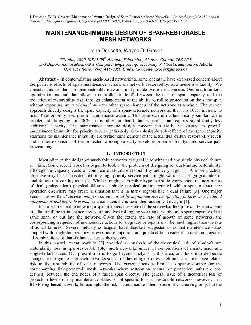
capacity during maintenance affect alterations in the network spare capacity distribution, and hence may also affect its theoretical restorability should a real failure occur while in that state. We understand that it is normal practice in ring-based networks (and transmission systems with APS) to speak of roll-to-protection as a way of moving working capacity over to spare capacity on the same span to facilitate repairs or upgrades on working channels or fibers. A similar logical concept applies in a mesh network but the roll-to-protection model becomes more general. Figure 1 illustrates four different basic functional models for the restorability-related effect of span maintenance, and terminology for referring to them.
working rolls to protection
any excess spare remains
fully contained (fully contained (wwii ≤≤ ssii))::
some working rolls to protectionand excess externally rerouted
all spare used up
partially contained (partially contained (wwii > > ssii))::
working externally rerouted
all spare withdrawn
fully exported:fully exported:
Figure 1 – Basic models for how span maintenance actions can affect network restorability.
In the fully contained model all working capacity, wi, is diverted (or “rolled”) over to spare capacity, si, on the maintenance span itself, with no need for external diversion rerouting. This is only possible if si
2
J. Doucette, W. D. Grover, “Maintenance-Immune Design of Span-Restorable Mesh Networks,” Proceedings of the 18th Annual National Fiber Optics Engineers Conference (NFOEC 2002), Dallas, TX, pp. 2049-2061, September 2002.
≥ wi. The effective amount of spare capacity remaining available to the network for protection uses is si,eff = si – wi.
In the partially contained model as much working capacity as possible first uses the same-span protection channels. Then, any further working capacity as needed (i.e., wi,eff = wi – si) is diverted to flow out over the network spares in general.
In the fully exported model all working capacity is referred out to the network for detouring and all spare capacity of the span is withdrawn from network use. This would occur when the span maintenance action requires complete turndown of all the span capacity. From the standpoint of network restorability effects, this is the worst case as it is functionally indistinguishable from a complete cut on the span. Designing to support this kind of maintenance action without loss of restorability is therefore mathematically identical to designing for 100% restorability to all dual-failure considerations. We need not consider this model further as methods for complete dual-failure restorability are already provided in [1] and [2]. It will, however, still serve as a benchmark of comparative interest for our results.
In general, therefore, depending on the relative si and wi capacities on the span, we can get instances of fully or partially contained maintenance states. If the amount of spare capacity, si, on a span undergoing maintenance exceeds (or equals) its working capacity, wi, then the net effect is a withdrawal of wi units of spare capacity on span i, leaving si,eff = si – wi remaining spare capacity on span i for use in restoration of failures on another span, acting as the full contained model. If the amount of spare capacity is not sufficient to contain the rollover within the span (i.e., wi > si), then the wi,eff = wi – si remaining paths are diverted in a mesh-like way over the spare capacity distributed throughout the network, acting as the partially contained model. The wi,eff diverted through the network are handled just as if span restoration was being performed on these lightpaths. All three models for the effects of maintenance consume spare capacity and so could result in a network state where there may not be enough spare capacity remaining to achieve full restoration of the failed channels on another span should it fail while in the maintenance state.
1.2. Concept of Maintenance-Related Risk Fields The concept of risk fields, or the theoretical exposure to restorability loss elsewhere in the network
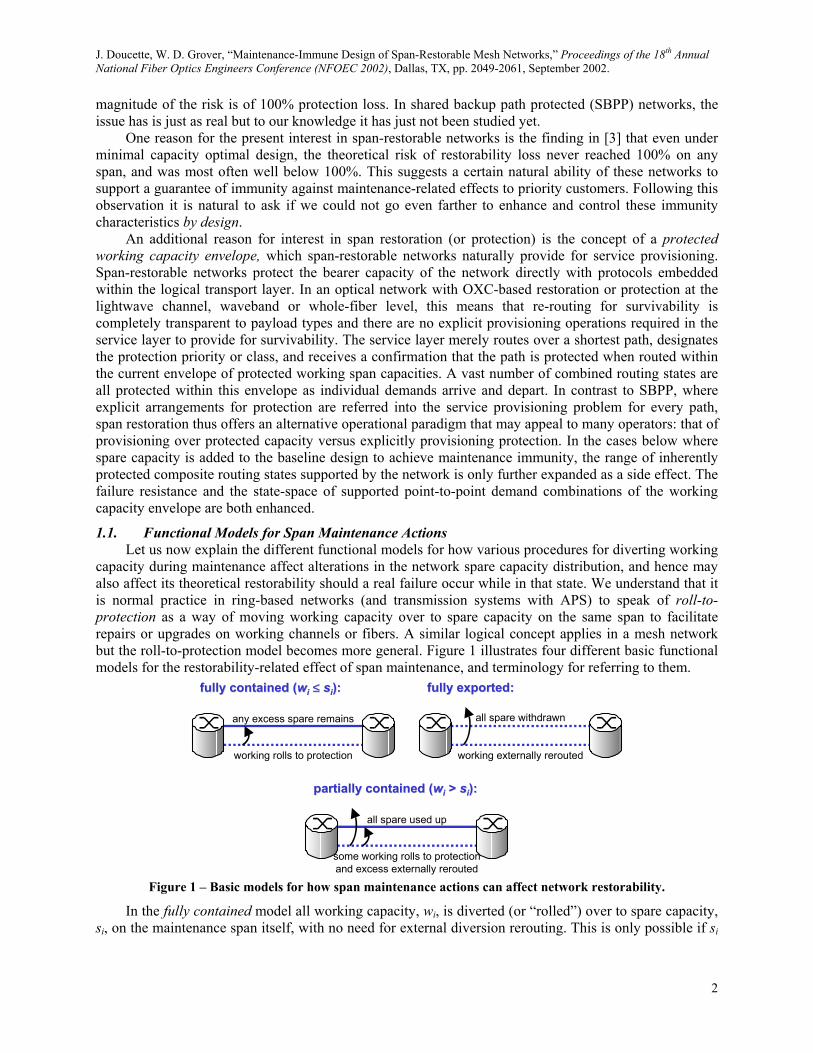
as a result of a maintenance action, was introduced in [3]. A risk field represents the extent to which a specific location and type of span maintenance action will impair the achievable restoration levels of other spans should they fail while in that maintenance state. For a given maintenance action, every other span has a risk field value equivalent to its loss of restorability (i.e., the percentage of wavelengths crossing it that is no longer restorable if that span fails). Work in [3] showed that under the partially contained model, restorability loss due to maintenance actions on some spans could extend through half the network’s spans, with some spans suffering 50% or more theoretical loss of restorability. However, unlike in rings, no span was ever seen to suffer the 100% restorability risk that arises on same-ring spans due to span maintenance. A typical risk field is illustrated conceptually in Figure 2.
13
8
M
9
30
10
28
17
44
31
14
Figure 2 – Illustrating the concept of a risk field for restorability loss for a span (M) under maintenance.
The maintenance span is marked “M” and the numbers on other spans are the percentage loss of restorability should that span fail while span M is under maintenance. The total magnitude of the risk field due to a maintenance action on a certain span is then defined as the sum of the number of all unit-hop
3

J. Doucette, W. D. Grover, “Maintenance-Immune Design of Span-Restorable Mesh Networks,” Proceedings of the 18th Annual National Fiber Optics Engineers Conference (NFOEC 2002), Dallas, TX, pp. 2049-2061, September 2002.
working channels that lose their restorability. For span M in Figure 2, the total risk field magnitude is 204, or the sum of the individual risk field values for each span experiencing loss of restorability. Averaged over all spans as maintenance spans, we obtain the average risk field magnitude for span maintenance in that network. Loss of restorability due to maintenance actions can arise as a result of two main causes: spare capacity contention and replacement path failure. Spare capacity contention refers to a situation where upon failure, the restoration mechanism is unable to find sufficient restoration routes for all of the failed working paths because maintenance replacement paths have made use of required spare capacity. The outcome in such cases can depend on the adaptability of the restoration mechanism. Replacement path failure refers to a situation where the physical failure strikes a span where spare capacity is currently being used to support one or more of the maintenance diversion paths.
1.3. Outline and Objectives Obviously any risk of restorability loss is undesirable if it can be avoided, so in Section 2 we test
some ideas for first reducing the extent and magnitude of maintenance-related risk fields. This yields some simple changes to the basic capacity design models that can improve the inherent ability to cope with maintenance actions, with little added cost. In Section 3 we then ask more generally: How could we optimally invest in additional capacity to achieve complete immunity to maintenance states? How does this compare to the capacity needed for full dual-failure restorability? We present our experimental methods in Section 4, and provide results in Section 5. We close with a summary discussion in Section 6.
2. MAINTENANCE AWARE BI-CRITERIA DESIGN METHOD A simple observation when considering partially contained roll-to-protection is that risk fields will
be minimized by maximizing the extent to which diverted working paths are contained on spare capacity of the same span. By its nature, partially contained roll-to-protection will only consume network spare capacity if its own spare capacity is exceeded by its working capacity. Should the span’s working capacity exceed its spare, then additional spare capacity distributed throughout the network will also be utilized to affect the maintenance diversion. So we expect that the closer we get to wi ≤ si for each span, the lower the theoretical risk field will be.
The design model for Maintenance Aware Spare Capacity Assignment (MA-SCA) takes the form of a bi-criteria integer programming (IP) model. The idea is to simultaneously minimize the cost of spare capacity plus a pseudo-cost or penalty term based on the number of working channels that cannot be diverted within their own spans. While this does not eliminate the loss of restorability due to maintenance actions, it can have two effects on the solution, depending on the weight (α) placed on the penalty term. At relatively light α the effect will be solely to bias the solution towards selecting amongst cost-equivalent solutions for an actual distribution of spare capacities that has a better overall matching in terms of wi ≅ si. At higher α values the effect will be to invest in additional spare capacity to further enhance the number of fully contained spans (i.e., those where s i ≥ wi). This is similar to the recent use of a bi-criteria design technique to secondarily optimize spare capacity to shorten the implied lengths of restoration routes [5]. The MA-SCA design model is as follows: Parameters: • Cj = cost of placing a spare (or working) channel on span j. • S = set of network spans. • α = alpha parameter trading off weight of two terms in the objective function. • wi = number of working channels on span i. • Pi = set of eligible resoration routes that can be used to divert or restore working channels on span i. • ,i p
jδ = 1 if restoration (or diversion) route p for failure of span i crosses span j, zero otherwise. Variables: • sj = number of spare channels required on span j, sj ≥ 0. • wsj = max{(wj – sj), 0}, wsj ≥ 0. • p
if = number of restoration paths assigned to the pth eligible route for failure of span i, . 0pif ≥
4
J. Doucette, W. D. Grover, “Maintenance-Immune Design of Span-Restorable Mesh Networks,” Proceedings of the 18th Annual National Fiber Optics Engineers Conference (NFOEC 2002), Dallas, TX, pp. 2049-2061, September 2002.
MA-SCA: (1) j j jj S j S
min C s wsα∈ ∈
⋅ ⋅+∑ ∑Subject to:
Restoration flow: i
pi i
p Pf w
∈
=∑ (2) i S∀ ∈
Spare capacity: (3)
,
i
i p pj j
p P
s fδ∈
≥ ⋅∑ i , , i S j S i j∀ ∈ ∈ ≠
wsj metric calculation: j jws w s≥ − j ; 0jws ≥ j S∀ ∈ (4)
The objective function (1) minimizes the total cost of spare capacity plus a penalty term incurred when diversion of working capacity for a maintenance action cannot be fully contained within the span itself. By increasing α, a planner can allow a controlled increase in spare capacity to minimize the amount of externally diverted working flow in the partially contained roll-to-protection type of maintenance. Constraint set (2) ensures sufficient restoration flow to fully restore the working wavelengths on failed span i, while constraint set (3) places enough spare capacity on each span j to accommodate the maximum restoration flow simultaneously imposed on it for any span failure. Constraint set (4) sets wsj values to be the maximum of wj – sj and 0 for any span j, so that the objective function’s secondary term can account for its related “cost.” Results for this approach follow in Section 5.1.
3. MAINTENANCE IMMUNE RESTORABILITY DESIGN Let us now go a step further than simply enhancing the design to contain diverted maintenance flows
and consider design of span-restorable networks that remain fully restorable for any single span failure in the presence of any maintenance action. We define a span i as being immune to a maintenance action on span h if span i maintains its full restorability when working channels on a span h are rolled to protection under the generalized partially contained model. A network as a whole is said to be maintenance immune if all spans are immune to all maintenance actions. Using this concept we develop a design model that will assure complete network-wide maintenance immunity. Previously defined parameters and variables are re-used as needed. In addition we have: New variables: • lh = number of working channels that a maintenance diversion places on spare capacity on the
maintenance span h itself, lh ≥ 0. • = number of working channels from maintenance span h that are assigned to eligible diversion
path p in the presence of failure on span i, m .
,h pim
, 0h pi ≥
• ,h pif = number of restoration paths assigned to the pth eligible restoration route for failure of span i
while span h is undergoing maintenance, . , 0h pif ≥
MI-SCA: (5) j jj S
min C s∈
⋅∑Subject to:
Maint. rest. flow: ,
: not in
h
h ph i
p Pi p
l m∈
+ = hw∑ (6) , , h S i S h∀ ∈ ∈ ≠ i
Failure rest. flow: ,
:i
h pi i
p Pf w
∈
=∑ (7) , , h S i S h∀ ∈ ∈ ≠ i
,iSpare capacity:
, , ,
i h
i p h p h p h pj j i j
p P p P
s fδ δ∈ ∈
≥ ⋅ + ⋅∑ ∑ m, ,
,
h S i Sj S h i j
∈ ∈∀
∈ ≠ ≠ (8)
5
J. Doucette, W. D. Grover, “Maintenance-Immune Design of Span-Restorable Mesh Networks,” Proceedings of the 18th Annual National Fiber Optics Engineers Conference (NFOEC 2002), Dallas, TX, pp. 2049-2061, September 2002.
Maint. capacity: (9)
, ,
i
i p h ph h i
p P
s fδ∈
≥ ⋅∑ hl+ i
i
i
, , h S i S h∀ ∈ ∈ ≠
The objective function (5) minimizes the total cost of spare capacity required to make the network fully restorable to any combination of maintenance action and span failure. Constraint set (6) ensures enough local roll-to-protection flow and additional diverted replacement paths to fully reroute all working channels on each maintenance span, while constraint set (7) ensures enough restoration flow to reroute working wavelengths on each failed span. Constraint set (8) places sufficient spare capacity on each non-failed and non-maintenance span to accommodate the maximum restoration flow simultaneously imposed on it for any combination of span failure and maintenance action. Constraint set (9) places enough spare capacity on the maintenance span to accommodate flows routed over it for restoration of any span failure plus the locally “rolled” capacity to protect its own maintenance. Note that Constraint sets (8) and (9) both apply simultaneously, so that whichever consideration is most binding on the spare capacity requirement of a span, maintenance diversion or restoration of other failures, will set the final value of spare capacity. Keep in mind that sj and sh are not separate variables, it is just the basic spare capacity variable being indexed in one instance from a failure scenario standpoint, in the other from a maintenance scenario standpoint.
3.1. Designing to Assert the Fully Contained Roll-to-Protection Model The MI-SCA formulation as defined refers in general to the partially contained roll-to-protection
model. To represent the fully contained model where diversion routes cannot be placed externally from the maintenance span, we transform constraint set (6) into (10) and transform constraint set (8) into (11).
Maint. rest. flow: (10) h hl w= , , h S i S h∀ ∈ ∈ ≠
Spare capacity:
, ,
i
i p h pj j
p P
s fδ∈
≥ ⋅∑, ,
,
h S i Sj S h i j
∈ ∈∀
∈ ≠ ≠ (11)
Constraint set (10) now forces the protection mechanism to roll all of the working channels on the maintenance span onto spare capacity fully contained on the span itself. And since there are no working channels from the maintenance span rerouted throughout the network, the last term in constraint set (8) can be dropped to create constraint set (11).
3.2. Accomodating the Fully Exported Roll-to-Protection Model Designing a network for immunity to fully exported maintenance diversion is equivalent to the dual-
failure design problem. The MI-SCA model can be appropriately modified by transforming constraint set (6) into (12), eliminating (9), and adding new constraint sets (13) and (14) below.
Maint. rest. flow: ,
h
h pi h
p Pm w
∈
=∑ (12) , , h S i S h∀ ∈ ∈ ≠ i
i
i
Restricted flow 1: (13) ,
: in
0i
h pi
p Ph p
f∈
=∑ , , h S i S h∀ ∈ ∈ ≠
Restricted flow 2: (14) ,
: in
0h
h pi
p Pi p
m∈
=∑ , , h S i S h∀ ∈ ∈ ≠
Constraint set (12) is essentially a duplicate of constraint set (7) except that it refers to the diversion of working channels on the maintenance span while span i has subsequently failed, effectively setting
values needed in constraint set (8). Constraint sets (13) and (14) generate enough spare capacity elsewhere in the network so that restoration remains possible without assuming any spare capacity use of the maintenance span. Note that if representing the true dual-failure design model (DF-SCA), we would not need separate and
,h pim
,h pim ,h p
if variables, and equations (12) and (14) could therefore both be eliminated, since we would now be making no distinction between spans h and i (they would both be failed spans).
6
J. Doucette, W. D. Grover, “Maintenance-Immune Design of Span-Restorable Mesh Networks,” Proceedings of the 18th Annual National Fiber Optics Engineers Conference (NFOEC 2002), Dallas, TX, pp. 2049-2061, September 2002.
Later results in Section 5.2 (Figure 6) that refer to the dual-failure design model are generated using this altered model.
3.3. Joint Working and Spare Maintenance Immune Capacity Design MI-SCA can be extended to jointly optimize the routing of working paths and the placement of
working and spare capacity (MI-JCA). This will in principle reduce the amount of extra spare capacity required to achieve full maintenance immunity. New parameters and variables become involved, primarily dealing with decisions about working path routing and capacities. Equation (5) becomes equation (15), and we add equations (16) and (17) to the formulation. New input parameters: • D = set of origin-destination (O-D) demand pair relations. • Qr = set of eligible working routes for demand pair r. • dr = number of wavelengths on demand pair r. • ,r q
jζ = 1 if working route q for demand relation r crosses span j, zero otherwise. New variables: • gr,q = working flow on working route q for demand pair r, gr,q ≥ 0. • wi = number of working wavelengths on span i (changes from a parameter to a variable), wi ≥ 0.
MI-JCA: (15) (j j jj S
min C s w∈
⋅ +∑ )
i
Working flow: (16) ,
r
r q r
q Q
g d∈
=∑ i D∀ ∈
Spare capacity: (17) , ,
r
r q r qj j
r Dq Q
w gζ∈∈
= ⋅∑ , , i S j S i j∀ ∈ ∈ ≠
New constraints (16) ensure that all channels for each O-D pair are routed and new constraint set (17) places enough working capacity on each span to accommodate all working flows routed over it.
3.4. Designing for an Acceptable Risk Residual A network planner might alternately be interested in specifying an acceptable risk of partial
restorability loss, less than 100% immunity. The maintenance immune design model can be modified to allow for such a user-controlled trade off between maintenance-related risk to restorability and increased design cost. We add a new parameter, replace constraint set (7) with (18), and bring in constraint sets (2) and (3) from the MA-SCA model. New input parameter: • = level of restorability required for failure of span i while another span is in a maintenance state, 0
≤ ≤ 1. iλ
iλFailure rest. flow: i (18) ,
:h
h pi i
p Pf w λ
∈
= ⋅∑ , , h S i S h∀ ∈ ∈ ≠
New constraints (18) provide enough restoration flow for each failed span to restore a specified percentage of that span’s channels in the presence of any maintenance action. We also need to take constraint sets (2) and (3) from the MA-SCA model and re-use them in this model in order that we still provide full restorability to any single span failure when not coincident with a maintenance action. These two constraints were not required in the basic MI-SCA model since it is implicit in constraint set (7) that if each span is restorable in the presence of any maintenance action, it must also be restorable in isolation. However, using constraint set (18) without these two added constraints explicitly providing full single-failure restorability, we may only be allocating enough capacity for the specified level of restorability even if the failure occurs in isolation.
7
J. Doucette, W. D. Grover, “Maintenance-Immune Design of Span-Restorable Mesh Networks,” Proceedings of the 18th Annual National Fiber Optics Engineers Conference (NFOEC 2002), Dallas, TX, pp. 2049-2061, September 2002.
4. TEST CASES AND EXPERIMENTAL METHODS Several test networks were used to explore the design ideas above. The MA-SCA tests were based
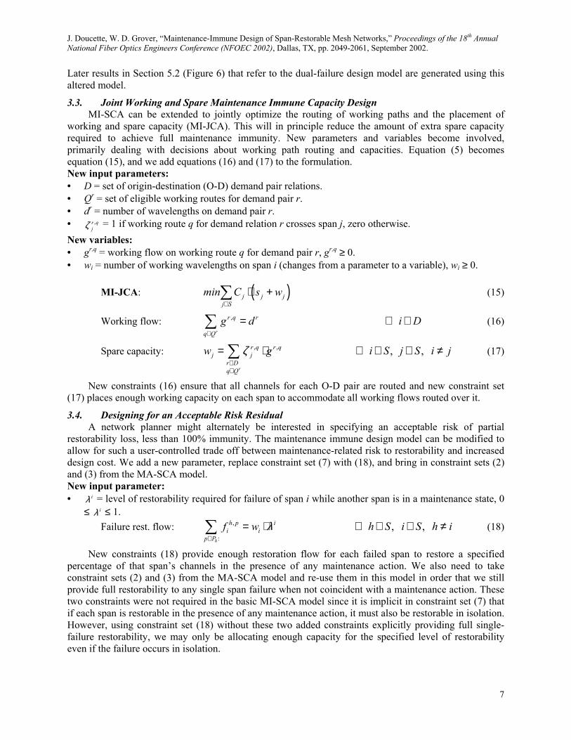
on three test networks, one with 20 nodes and 28 spans (20n28s1), one with 20 nodes and 40 spans (20n40s1), and one with 40 nodes and 70 spans (40n70s1). 20n40s1 and 40n70s1 are shown in Figure 3. 20n28s1 is the same test network used in [5]. MI-SCA test case networks are divided into two groups. The first group is a family of networks based on 40n70s1 where each subsequent member of the family is produced by randomly removing one span from the previous member, while retaining bi-connectivity. This is the same basic method used to study effects of varying nodal degree in [6]. The second group of MI-SCA test networks is a selection of five networks ranging from 15 nodes up to 45 nodes (including 20n40s1 and 40n70s1 already described), all shown in Figure 3. For each test network, the length of each span is the Euclidean distance on the plane between the end nodes the span connects. Capacity costs for all test cases are taken as proportional to the length of the span and the number of spare channels required on the span.
15n30s1 20n40s1
25n50s1 45n90s140n70s1
Figure 3 – Test case networks.
For all the test cases each O-D node pair exchanges a randomly generated number of wavelength demands following a uniform random distribution between 1 and 10. All working and spare capacity allocations were integer, corresponding to capacity design and restoration mechanisms operating at the wavelength channel level. All lightpath demands were first routed along their shortest paths (by total span-distance, not span-count). The design models were implemented in AMPL and solved with the Parallel CPLEX 7.1 MIP Solver on a 4-processor Ultrasparc Sun Server at 450 MHz with 4 GB of RAM running the Sun Solaris 8 Operating Environment. Results were based on full CPLEX terminations using a MIPGAP of 10-4, meaning all solutions are guaranteed to be within 0.01% of optimal. Problems solved in seconds or a few minutes with the exception of the MI-JCA models, which took as much as several hours for the largest test cases. The run-times are not a concern at present because the purpose is research understandings of the networking concepts and phenomena. Separate work can follow to operationalize these processes with faster methods or heuristics, if warranted. A pre-processing program generates the sets of eligible routes for consideration as restoration routes under each failure scenario and working routes for each O-D node pair. These are generated with the method described in [6]. The same routes-sets represent the eligible routes for maintenance diversion.
We use conventional spare capacity allocation (SCA), joint working and spare capacity allocation (JCA), and dual-failure spare capacity allocation (DF-SCA) models as benchmarks to which we compare our new formulations. The SCA model is identical to the MA-SCA model except that equation (5) replaces equation (1) and we drop equation (4). The JCA model adds equations (16) and (17) to the SCA model and replaces the objective function with equation (15). The DF-SCA model is as described in Section 3.2.
8
J. Doucette, W. D. Grover, “Maintenance-Immune Design of Span-Restorable Mesh Networks,” Proceedings of the 18th Annual National Fiber Optics Engineers Conference (NFOEC 2002), Dallas, TX, pp. 2049-2061, September 2002.
5. RESULTS AND DISCUSSION
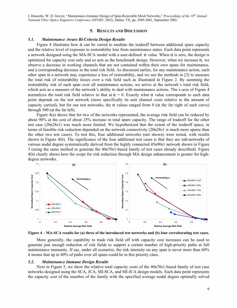
5.1. Maintenance Aware Bi-Criteria Design Results Figure 4 illustrates how α can be varied to mediate the tradeoff between additional spare capacity
and the relative level of exposure to restorability loss from maintenance states. Each data point represents a network designed using the MA-SCA model with a user-defined α value. When α is zero, the design is optimized for capacity cost only and so acts as the benchmark design. However, when we increase α, we observe a decrease in working channels that are not contained within their own spans for maintenance, and a corresponding decrease in the total risk field. As discussed earlier, for any maintenance action, each other span in a network may experience a loss of restorability, and we use the methods in [3] to measure the total risk of restorability losses over a risk field such as illustrated in Figure 2. By summing the restorability risk of each span over all maintenance actions, we arrive at the network’s total risk field, which acts as a measure of the network’s ability to deal with maintenance actions. The x-axis of Figure 4 normalizes the total risk field relative to that at α = 0. Exactly what α value corresponds to each data point depends on the test network (more specifically its unit channel costs relative to the amount of capacity carried), but for our test networks, the α values ranged from 0 (at the far right of each curve) through 500 (at the far left).
Figure 4(a) shows that for two of the networks represented, the average risk field can be reduced by about 90% at the cost of about 25% increase in total spare capacity. The range of tradeoff for the other test case (20n28s1) was much more limited. We hypothesized that the extent of the tradeoff space, in terms of feasible risk reduction depended on the network connectivity (20n28s1 is much more sparse than the other two test cases). To test this, four additional networks (not shown) were tested, with results shown in Figure 4(b). The significance of the four additional test cases is that they are sub-networks of various nodal degree systematically derived from the highly connected 45n90s1 network shown in Figure 3 (using the same method to generate the 40n70s1-based family of test cases already described). Figure 4(b) clearly shows how the scope for risk reduction through MA design enhancement is greater for high-degree networks.
1
1.05
1.1
1.15
1.2
1.25
1.3
0 0.2 0.4 0.6 0.8 1
Relative Average Risk Field
Nor
mal
ized
Spa
re C
apac
ity C
ost
20n28s1
20n40s1
40n70s1
Increasing α
(a)
1
1.1
1.2
1.3
1.4
1.5
1.6
0 0.2 0.4 0.6 0.8 1
Relative Average Risk Field
Nor
mal
ized
Spa
re C
apac
ity C
ost
45n90s1-Full
45n90s1-80s
45n90s1-70s
45n90s1-60s
Increasing α
(b)
Figure 4 – MA-SCA results for (a) three of the introduced test networks and (b) four corroborating test cases.
More generally, the capability to trade risk field off with capacity cost increases can be used to generate just enough reduction of risk fields to support a certain number of high-priority paths at full maintenance immunity. If say, under all scenarios, the risk intensity on any span is never more than 60% it means that up to 40% of paths over all spans could be in this priority class.
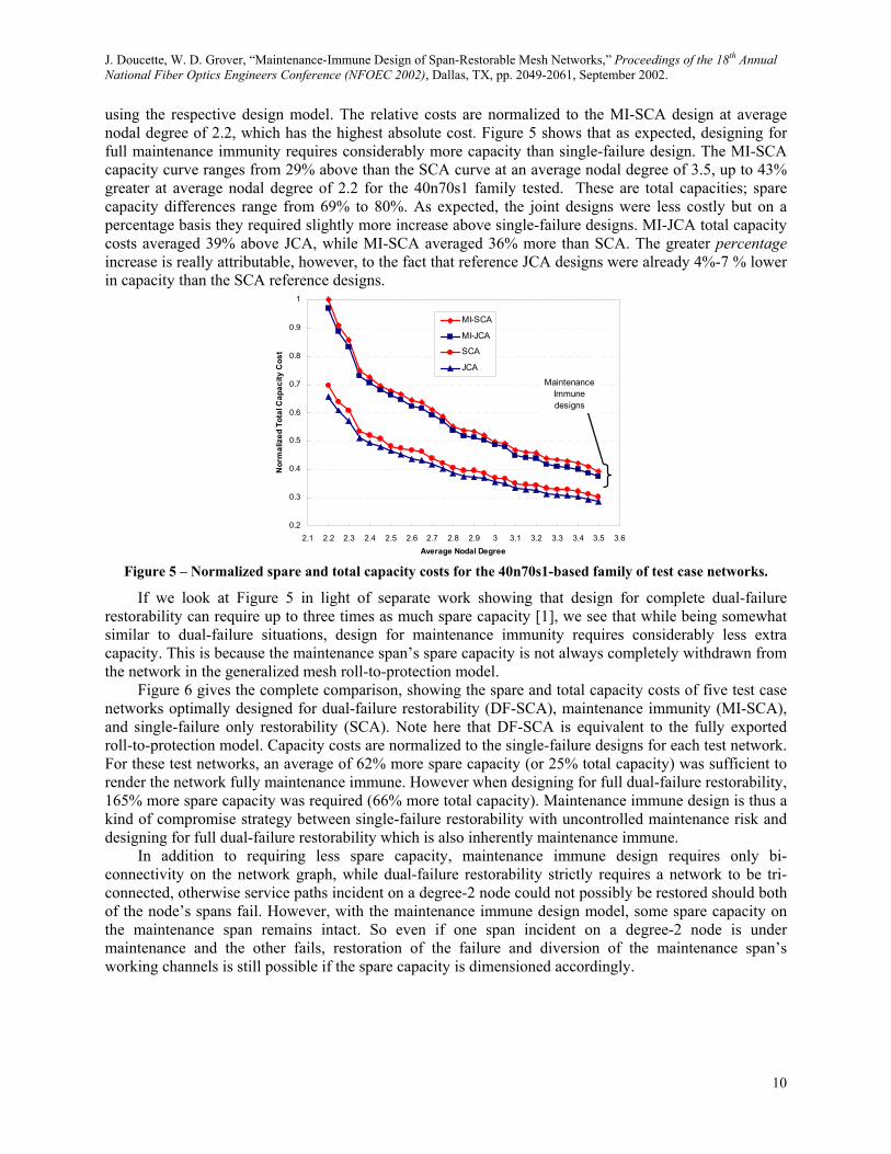
5.2. Maintenance Immune Design Results Next in Figure 5, we show the relative total capacity costs of the 40n70s1-based family of test case
networks designed using the SCA, JCA, MI-SCA, and MI-JCA design models. Each data point represents the capacity cost of the member of the family with the specified average nodal degree optimally solved
9
J. Doucette, W. D. Grover, “Maintenance-Immune Design of Span-Restorable Mesh Networks,” Proceedings of the 18th Annual National Fiber Optics Engineers Conference (NFOEC 2002), Dallas, TX, pp. 2049-2061, September 2002.
using the respective design model. The relative costs are normalized to the MI-SCA design at average nodal degree of 2.2, which has the highest absolute cost. Figure 5 shows that as expected, designing for full maintenance immunity requires considerably more capacity than single-failure design. The MI-SCA capacity curve ranges from 29% above than the SCA curve at an average nodal degree of 3.5, up to 43% greater at average nodal degree of 2.2 for the 40n70s1 family tested. These are total capacities; spare capacity differences range from 69% to 80%. As expected, the joint designs were less costly but on a percentage basis they required slightly more increase above single-failure designs. MI-JCA total capacity costs averaged 39% above JCA, while MI-SCA averaged 36% more than SCA. The greater percentage increase is really attributable, however, to the fact that reference JCA designs were already 4%-7 % lower in capacity than the SCA reference designs.
0.2
0.3
0.4
0.5
0.6
0.7
0.8
0.9
1
2.1 2.2 2.3 2.4 2.5 2.6 2.7 2.8 2.9 3 3.1 3.2 3.3 3.4 3.5 3.6Average Nodal Degree
Nor
mal
ized
Tot
al C
apac
ity C
ost
MI-SCA
MI-JCA
SCA
JCAMaintenance
Immune designs
Figure 5 – Normalized spare and total capacity costs for the 40n70s1-based family of test case networks.
If we look at Figure 5 in light of separate work showing that design for complete dual-failure restorability can require up to three times as much spare capacity [1], we see that while being somewhat similar to dual-failure situations, design for maintenance immunity requires considerably less extra capacity. This is because the maintenance span’s spare capacity is not always completely withdrawn from the network in the generalized mesh roll-to-protection model.
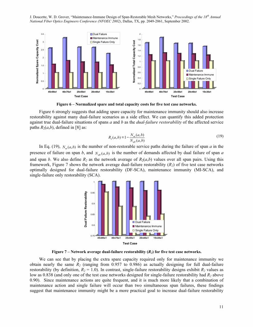
Figure 6 gives the complete comparison, showing the spare and total capacity costs of five test case networks optimally designed for dual-failure restorability (DF-SCA), maintenance immunity (MI-SCA), and single-failure only restorability (SCA). Note here that DF-SCA is equivalent to the fully exported roll-to-protection model. Capacity costs are normalized to the single-failure designs for each test network. For these test networks, an average of 62% more spare capacity (or 25% total capacity) was sufficient to render the network fully maintenance immune. However when designing for full dual-failure restorability, 165% more spare capacity was required (66% more total capacity). Maintenance immune design is thus a kind of compromise strategy between single-failure restorability with uncontrolled maintenance risk and designing for full dual-failure restorability which is also inherently maintenance immune.
In addition to requiring less spare capacity, maintenance immune design requires only bi-connectivity on the network graph, while dual-failure restorability strictly requires a network to be tri-connected, otherwise service paths incident on a degree-2 node could not possibly be restored should both of the node’s spans fail. However, with the maintenance immune design model, some spare capacity on the maintenance span remains intact. So even if one span incident on a degree-2 node is under maintenance and the other fails, restoration of the failure and diversion of the maintenance span’s working channels is still possible if the spare capacity is dimensioned accordingly.
10
J. Doucette, W. D. Grover, “Maintenance-Immune Design of Span-Restorable Mesh Networks,” Proceedings of the 18th Annual National Fiber Optics Engineers Conference (NFOEC 2002), Dallas, TX, pp. 2049-2061, September 2002.
0
0.5
1
1.5
2
2.5
3
3.5N
orm
aliz
ed S
pare
Cap
acity
Cos
t
45n90s1 40n70s1 25n50s1 20n40s1 15n30s1
Test Case
Dual FailureMaintenance ImmuneSingle Failure Only
0
0.2
0.4
0.6
0.8
1
1.2
1.4
1.6
1.8
2
Nor
mal
ized
Tot
al C
apac
ity C
ost
45n90s1 40n70s1 25n50s1 20n40s1 15n30s1
Test Case
Dual FailureMaintenance ImmuneSingle Failure Only
Figure 6 – Normalized spare and total capacity costs for five test case networks.
Figure 6 strongly suggests that adding spare capacity for maintenance immunity should also increase restorability against many dual-failure scenarios as a side effect. We can quantify this added protection against true dual-failure situations of spans a and b as the dual-failure restorability of the affected service paths R2(a,b), defined in [8] as:
nr2
aff
( , )( , ) 1( , )
N a bR a bN a b
= − (19)
In Eq. (19), nr ( , )N a b is the number of non-restorable service paths during the failure of span a in the presence of failure on span b, and aff ( , )N a b is the number of demands affected by dual failure of span a and span b. We also define R2 as the network average of R2(a,b) values over all span pairs. Using this framework, Figure 7 shows the network average dual-failure restorability (R2) of five test case networks optimally designed for dual-failure restorability (DF-SCA), maintenance immunity (MI-SCA), and single-failure only restorability (SCA).
0.75
0.8
0.85
0.9
0.95
1
Dua
l Fai
lure
Res
tora
bilit
y
45n90s1 40n70s1 25n50s1 20n40s1 15n30s1
Test Case
Dual FailureMaintenance ImmuneSingle Failure Only
Figure 7 – Network average dual-failure restorability (R2) for five test case networks.
We can see that by placing the extra spare capacity required only for maintenance immunity we obtain nearly the same R2 (ranging from 0.957 to 0.986) as actually designing for full dual-failure restorability (by definition, R2 = 1.0). In contrast, single-failure restorability designs exhibit R2 values as low as 0.838 (and only one of the test case networks designed for single-failure restorability had R2 above 0.90). Since maintenance actions are quite frequent, and it is much more likely that a combination of maintenance action and single failure will occur than two simultaneous span failures, these findings suggest that maintenance immunity might be a more practical goal to increase dual-failure restorability
11
J. Doucette, W. D. Grover, “Maintenance-Immune Design of Span-Restorable Mesh Networks,” Proceedings of the 18th Annual National Fiber Optics Engineers Conference (NFOEC 2002), Dallas, TX, pp. 2049-2061, September 2002.
12
than explicitly designing for R2 = 1.0. Capacity requirements are considerably less but the network is most of the way to dual-failure restorability.
6. SUMMARY This work has introduced several approaches to dealing with the effects of maintenance actions on
the restorability of a span-restorable network. The first is a bi-criteria mathematical model through which one can trade an increase in capacity cost in exchange for a decrease in average risk field due to maintenance diversion that is not wholly contained on the maintenance span itself. It was found that in highly connected graphs this strategy of simply enhancing the same-span containment effect could reduce 90% of the risk. The other main strategy is a design model that strictly eliminates all single-span maintenance risk. Test cases showed that for a 25% increase in capacity one could ensure full protection against span failures while in a maintenance state on any other span in the network. In the same test cases, designing for complete dual-failure restorability required approximately 66% more total capacity. The maintenance-immune design approach also has the additional benefit of significantly increasing the dual-failure restorability of the network as a whole and of further expanding its protected working capacity envelope for operational provisioning use.
7. ACKNOWLEDGEMENTS The authors wish to thank William Glenn of TRLabs and the University of Alberta for providing
software support and assistance. 8. REFERENCES
[1] M. Clouqueur, W. D. Grover, “Computational and Design Studies on the Unavailability of Mesh-restorable Networks,” Proceedings of the 2nd International Workshop on the Design of Reliable Communication Networks (DRCN 2000), Munich, Germany, pp. 181-186, April 2000.
[2] M. Clouqueur, W. D. Grover, “Mesh-restorable networks with complete dual failure restorability and with selectively enhanced dual failure restorability properties,” Optical Networking and Communications Conference (OptiComm 2002), Boston, MA, in press, July-August 2002.
[3] W. D. Grover, M. Clouqueur, T. Bach, “Quantifying and Managing the Influence of Maintenance Actions on the Survivability of Mesh-Restorable Networks,” Proceedings of the 17th Annual National Fiber Optic Engineers Conference (NFOEC 2001), Baltimore, MD, vol. 3, pp. 1514-1525, July 2001.
[4] Cisco Systems, “Always-On Availability for Multiservice Carrier Networks: Prerequisites for High-Availability Infrastructures,” Cisco Systems White Papers, 1999.
[5] J. Doucette, W. D. Grover, T. Bach, “Bi-criteria studies of mesh network restoration path-length versus capacity tradeoffs,” Proceedings of OSA Optical Fiber Communications Conference and Exhibit (OFC 2001), Anaheim, CA, pp. TuG2-1–TuG2-3, March 2001.
[6] J. Doucette, W. D. Grover, “Comparison of Mesh Protection and Restoration Schemes and the Dependency on Graph Connectivity,” Proceedings of the 2nd International Workshop on the Design of Reliable Communication Networks (DRCN 2000), Budapest, Hungary, pp. 121-128, October 2001.
[7] M. Herzberg, S. J. Bye, A. Utano, “The Hop-Limit Approach for Spare-Capacity Assignment in Survivable Networks,” IEEE/ACM Transactions on Networking, vol. 3, no. 6, pp. 775-784, December 1995.
[8] M. Clouqueur, W. D. Grover, “Availability Analysis of Span-Restorable Mesh Networks,” IEEE Journal on Selected Areas in Communications (JSAC), vol. 20, no. 4, pp. 810-821, May 2002.

![Optical Amplifiers Placement in WDM Mesh Networks for ...kamal/Docs/hk09.pdf · Networks for Optical Multicasting Service Support ... for AOM traffic. The network cost in [1]](https://img.pdfslide.net/doc/110x75/5aa4b3237f8b9ab4788c3426/optical-ampliers-placement-in-wdm-mesh-networks-for-kamaldocshk09pdfnetworks.jpg)