Embed Size (px)
Citation preview
Maintenance
M 20 / M 20 C
Maintenance A0
en / 26.01.2011 AA047781 1/1

Total Index A0.01
-
en / 26.01.2011 AA047652 1/1
Maintenance A0
Total Index A0.01
Introduction A0.02
Emergency Stop Safety System A0.04
Maintenance A5
Table of Contents A5.01
Introduction A5.02

Introduction A0.02
M20/M25/M32/M43
en / 26/1/11 AA047587 1/1
The present operating instructions include notes and guidelines for proper handling of the engine plant. It is
matched with the equipment condition and the type of fuel sold.
Since the type of fuel used considerably influences the service life of the components, the Caterpillar after-sales service has to be consulted when it is required to change from destillate fuel operation to heavy fuel oil operation, in order to ensure an expert retrofit of the engine plant and to exchange the necessary docu-mentation. When changing over from heavy fuel oil operation to destillate operation, the Caterpillar after-sales service should also be consulted for a longer period of time so that a documentation with extended maintenance intervals can be made available.
With regard to operation and maintenance of the engine including the necessary work to be carried out, the
operating instructions are subdivided into the following chapters:
Operating Instructions
Maintenance
Technical Engine Data
Operating Media
Control/Regulation
Tool Catalogue
With the respective information contained in the individual chapters, the technical personnel is able to
maintain the engine in such a manner that regarding its output, reliability, economy and service life opti-
mum operating results can be achieved.
If you need further information or if you have any other questions, we kindly ask you to contact our respon-
sible service organization.
The operating instructions do not release the personnel in charge of this engine plant from their duty to take
care. The recognized rules of technology are to be observed, taking into account overriding regulations,
observance of the general safety measures and locally applicable accident prevention regulations. Data or
explanations assumed to be the basic knowledge of trained technical and engine room personnel, are not
contained.
Caterpillar Motoren GmbH Co. KG is not responsible for damage caused by improper operation and
maintenance.
These operating instructions are only intended for our customers. All rights reserved for this docu-ment. All technical data contained in these operating instructions must neither be reproduced, dis-
tributed nor utilized for competitive purposes or disclosed to third parties without our express
approval.
Postal address: Caterpillar Motoren GmbH & Co. KG, P.O. Box 9009, D-24157 Kiel
Telephone: +49(0)431- 3995-01(chief operator)
Telefax: +49(0)431-3995-2010(after-sales service only)
http://www.marine.cat.com

Emergency StopSafety System
A0.04
M20/M25/M32/M43
Actions that must be performed after a safety/emergency stop* occurred:
- Identify the reason for emergency stop based on the points listed below.
- Work through list of corresponding sub-points.
- Contact your Caterpillar Service.
Type of emergency stop:
1. Overspeed condition
2. Lubrication oil (pressure and temperature)
3. Engine room monitoring
4. Cooling water - fresh water - HT (pressure and temperature)
5. Exhaust gas
6. Check pneumatic emergency stop system on engine after every emergency stop
7. Fault messages and measuring points
WARNING
Do not perform further starting attempts for a while after the safety/emergency stop device has triggered!
Note and observe the following points and actions.
If these actions are not observed, severe personal injuries as well as damage to the engine can occur, which may void the warranty.
NOTE*
With some engine assemblies, in particular in marine applications, an alarm or a po-wer reduction may be triggered before a safety/emergency stop is performed. If there are no safety concerns, the engine must also be shut down, if an alarm occurs or en-gine power is reduced and the causes have to be eliminated.
en / 15.12.2010 AA033984 1/5

Emergency StopSafety System
A0.04
M20/M25/M32/M43
1. Overspeed condition
Emergency stop due to excessive rpm.
1.1 How high was the maximum rpm before emergency stop was triggered?
1.2 Why did engine go into an overspeed condition?
Check:
• Check if emergency stop safety device is operational.
• Check free operation of adjustment shaft and joint
• Check every single regulator rack of fuel pumps in both directions for proper operation by pulling and pressing.
• Checking governor drive.
• Verification of possible out of calibration of actuator (if fitted).
1.3 Contact your Caterpillar Service.
2. Lube oil (lube oil pressure, lube oil temperature)
2.1 Emergency stop due to lack of lube oil
Checks:
• Visual inspection of engine.
• Lube oil pump drive:- Check gears for damage or loss.
• Check lube oil pressure switch.
• Check lube oil filter for metal chips.
• Check oil sump and piping for leaks and cracks.
2.2 Contact the Caterpillar Service.
NOTE
The following checks may be of assistance during troubleshooting and permit identi-fication of root causes of an emergency stop. However, they cannot cover the entire spectrum of possible causes.
en / 15.12.2010 AA033984 2/5

Emergency StopSafety System
A0.04
M20/M25/M32/M43
2.3 Emergency stop due to high lube oil temperature
Checks:
• Check temperature sensor.
• Check oil cooler.
• Check cooling water circuit.
• Pressurize each cylinder through opened indexing valves with shop air. If there is a rapid pressure drop or if no pressure builds up the cause must be investigated.
2.4 Contact the Caterpillar/ MaK Service.
3. Engine room monitoring
Emergency Stop due to excessive oil mist concentrationsee engine documentation, chap-
ter "Operating Instructions".
Checks:
• Check engine room monitoring device (operational test), see "engine documentation, chapter "External Documentation" C5.05.11.02.03. nn.
• Visual inspection of engine and gear train,
• of cam shaft trough,
• of combustion chamber,
• of turbo charger.
3.1 Contact your Caterpillar Service.
4. Cooling water (fresh water - HT, pressure and temperature)
Emergency stop due to excessively high cooling water temperature
Checks:
• Visual inspection of engine
• Check temperature sensors
• Check fresh water cooler
• Operational test of LT - Cooling water circuit with cooling water pump.
4.1 Contact your Caterpillar Service.
en / 15.12.2010 AA033984 3/5

Emergency StopSafety System
A0.04
M20/M25/M32/M43
5. Exhaust gas
Emergency stop due to excessively high exhaust temperature
Checks:
• Check exhaust gas temperature sensors.
• Aftercooler (differential pressure) (refer to A5.05.06.04.02.nn).
• Fuel pumps and fill level scale on each fuel pump.
• Injection valves (refer to A5.05.07.08.01.nn).
• Turbocharger
5.1 Contact your Caterpillar Service.
6. Check pneumatic emergency stop system on engine after every emergency stop
Checks:
• Check emergency stop pneumatic system on the engine for leaks.
• Stop valve to main start line upstream from start valve must constantly be open during operation, see engine documentation, chapter "Operating Instructions".
NOTE
In order for emergency stop safety device to operate properly, 7,5 bar pneumatic supply has to be available continuously.
en / 15.12.2010 AA033984 4/5

Emergency StopSafety System
A0.04
M20/M25/M32/M43
7. Fault messages and measuring points
7.1 General fault messages:
Fault message: Description:(Measuring point number)
6105 * Low shutdown air pressure
9631 * Oil mist detector failure
9601 * Terminal set X1 voltage failure
9717 * Terminal set X3 voltage failure
* see also List of Measuring Points, see "engine documentation, chapter "Control/Regulati-
on". C5.05.02.01.nn.nn.
7.2 Plant-specific fault messages:
- Safety system failure
- RPM switch unit failure (overspeed)
7.3 Please contact the Caterpillar Customer Service.
CAUTION
The fault messages listed below do not directly lead to an emergency stop, but they considerably affect reliable engine operation.
If such a fault message appears on the monitoring display of the alarm system, the engine plant may only be operated for a short time and under permanent observati-on.
At any rate, the cause of the fault message must be remedied immediately.
en / 15.12.2010 AA033984 5/5

Maintenance A5
-
en / 26.01.2011 AA000026 1/1
Maintenance

Table of Contents A5.01
-
Maintenance A5
Table of Contents A5.01
Introduction A5.02
Periodical scheduleDistillate fuel A5.04.01
Periodical scheduleHeavy fuel A5.04.02
Engine, cylinder head A5.05.01
Valve Clearance A5.05.01.01.01.00
Valve clearance A5.05.01.01.01.02
Valve Rocker Brackets A5.05.01.02.01.00
Valve Rocker A5.05.01.02.02.00
Valve Rotator A5.05.01.03.01.00
Valve Guide / Oil Scraper Ring A5.05.01.05.01.01
Media line A5.05.01.05.50.00
Cylinder Head A5.05.01.06.01.00
Nozzle Sleeve A5.05.01.06.50.00
Inlet and Exhaust Valve Cones A5.05.01.07.01.01
Valve Cones A5.05.01.08.01.00
Inlet Valve Cones A5.05.01.08.01.01
Exhaust Valve Cones A5.05.01.08.01.03
Inlet Valve Cones A5.05.01.08.01.04
Valve Seat Ring A5.05.01.08.02.00
Valve Seat Ring A5.05.01.08.02.01
Cylinder Head A5.05.01.10.00.00
Cylinder Head A5.05.01.10.01.01
Cylinder Head A5.05.01.11.01.00
Engine, gear A5.05.02
Running Gear/Engine Timing A5.05.02.01.01.00
Crank Web Deflection A5.05.02.02.01.00
Bearing Shells A5.05.02.03.07.01
Al-Grooved Bearings A5.05.02.03.09.01
Big-End Bearings A5.05.02.04.01.01
Big-End Bearings A5.05.02.04.02.00
Main Bearings A5.05.02.05.01.01
Main Bearings A5.05.02.05.02.00
Piston A5.05.02.06.01.01
en / 26.01.2011 AA020041 1/4
Table of Contents A5.01
-
Piston A5.05.02.06.01.02
Piston Rings and Grooves A5.05.02.07.01.01
Piston Rings and Grooves A5.05.02.07.01.03
Piston A5.05.02.10.01.01
Engine, housing A5.05.03
Crankcase Explosion Relief Valves A5.05.03.01.01.00
Explosion Relief Valve A5.05.03.01.01.02
Explosion relief valve A5.05.03.01.01.03
Zylinderbuchse A5.05.03.03.01.02
Cylinder Liner A5.05.03.04.01.00
Cylinder Liner A5.05.03.04.02.00
Engine Bolting and Unions A5.05.03.07.01.00
Engine, control A5.05.04
Camshaft Bearing A5.05.04.01.01.00
Camshaft A5.05.04.04.01.00
Camshaft A5.05.04.04.01.01
Camshaft A5.05.04.04.01.02
Timing Gear Train A5.05.04.08.01.00
Governor Drive A5.05.04.08.03.00
Vibration damper on camshaft A5.05.04.09.01.00
Vibration damper on camshaft A5.05.04.09.01.01
Vibration Damper on Camshaft A5.05.04.09.01.02
Engine, regulation A5.05.05
Control shaft bedding A5.05.05.01.02.00
Fuel Limiter A5.05.05.04.01.00
Fuel Limiter A5.05.05.04.01.01
Servo-Actuator A5.05.05.04.02.00
Servo-Actuator A5.05.05.04.02.01
Starting Fuel Limiter A5.05.05.05.01.00
Control Valves A5.05.05.09.05.00
Compressed-Air Filter A5.05.05.09.06.00
Compressed-Air Filter A5.05.05.09.06.01
Regleröl A5.05.05.25.00.01
en / 26.01.2011 AA020041 2/4

Table of Contents A5.01
-
Engine, exhaust gas system/supercharging A5.05.06
Exhaust Manifold A5.05.06.01.01.00
Exhaust Manifold A5.05.06.01.01.01
Charge Air Cooler A5.05.06.04.02.00
Charge Air Cooler A5.05.06.04.02.01
Charge Air Cooler A5.05.06.04.02.02
Charge Air Cooler A5.05.06.04.02.03
Charge Air Cooler A5.05.06.04.02.04
Exhaust gas turbocharger A5.05.06.05.00.01
Exhaust gas turbocharger A5.05.06.05.01.01
Exhaust gas turbocharger A5.05.06.05.01.02
Exhaust gas turbochargerTurbine cleaning A5.05.06.05.02.03
Exhaust gas turbochargerTurbine cleaning A5.05.06.05.02.04
Turbocharger A5.05.06.13.01.00
Turbocharger A5.05.06.13.01.01
Turbocharger A5.05.06.13.01.02
Turbocharger A5.05.06.13.01.03
Turbocharger A5.05.06.13.01.04
Turbocharger A5.05.06.13.01.05
Exhaust gas turbocharger A5.05.06.13.01.06
Abgasturbolader A5.05.06.13.01.07
Turbocharger A5.05.06.13.01.08
Exhaust gas turbocharger - HPR 5000 -(KBB) A5.05.06.13.02.11
Exhaust gas turbocharger - HPR 4000 -(KBB) A5.05.06.13.02.12
Engine, fuel system A5.05.07
Injection Pump A5.05.07.02.01.00
Injection Pump A5.05.07.02.01.01
Injection Pump A5.05.07.02.01.02
Injection Pump A5.05.07.03.01.00
Injection Pump A5.05.07.03.01.01
Injection Pump A5.05.07.03.01.02
Injection Pump A5.05.07.03.01.03
Fuel Injector A5.05.07.07.01.00
Fuel Injector A5.05.07.07.01.02
en / 26.01.2011 AA020041 3/4

Table of Contents A5.01
-
Fuel Injector A5.05.07.08.01.01
Fuel Injector A5.05.07.08.01.02
Fuel Injector A5.05.07.09.01.00
Fuel Injector A5.05.07.09.01.01
Duplex Fuel Filter A5.05.07.12.01.00
Duplex Fuel Preliminary Filter A5.05.07.12.02.02
Duplex Fuel Preliminary Filter A5.05.07.12.02.04
Fuel Feed Pump A5.05.07.13.01.00
Fuel Distributor Line/Manifold Line A5.05.07.15.01.00
Fuel / Fuel collector rail A5.05.07.15.01.01
Engine, lubricating oil system A5.05.08
Lubricating Oil System A5.05.08.02.01.00
Lube Oil Pump A5.05.08.03.01.00
Lube Oil Pump A5.05.08.03.02.00
Lubricating Oil Duplex Filter A5.05.08.04.01.00
Oil pressure control valve A5.05.08.05.01.00
Oil pressure control valve A5.05.08.05.01.01
Prelubricating pump/Prelubrication A5.05.08.10.00.00
Engine, cooling water system A5.05.09
Centrifugal Cooling Water Pump A5.05.09.07.01.00
Centrifugal Cooling Water Pump A5.05.09.07.01.01
Centrifugal Cooling Water Pump A5.05.09.07.01.04
Engine control equipment A5.05.11
Pressure Switches A5.05.11.01.02.01
Pressure Switches A5.05.11.01.03.00
RPM Switch A5.05.11.05.01.02
Lubricating Oil/Cooling Water Thermostat A5.05.11.06.01.00
Lubricating Oil/Cooling Water Thermostat A5.05.11.06.01.01
Pressure Switch A5.05.11.06.05.02
Pressure Switch A5.05.11.06.06.02
Crankcase Monitoring Device A5.05.11.09.01.03
Engine auxiliary units A5.05.12
Vibration Damper A5.05.12.04.01.03
en / 26.01.2011 AA020041 4/4

Introduction A5.02
M20/M25/M32/M43
1. General
It is assumed that the engine room personnel has the necessary knowledge and experi-ence required for the proper maintenance and servicing of diesel engines. For this rea-son and in the interest of clearness we did not go too much into details in themaintenance documents.
No claims can be raised owing to missing instructions in the maintenance documents, ifdamage is caused by improper handling.
All information refers to the date of printing.
2. Explanation of the maintenance system
2.1 Scheduled maintenance
Without “Scheduled maintenance” the economic operation of supercharged engine is inthe long run not possible at today's state of art.
The explanations are used to make the user of this engine plant familiar with the existingmaintenance system of Caterpillar Motoren GmbH & Co. KG and to interest and deepenthe understanding of the user for the problems and importance of the “Scheduledmaintenance”.
It is the purpose of the maintenance to replace parts subject to wear and tear or to repairthese parts before they are damaged.
The “Scheduled maintenance” is thereby supported by inspections according to fixeddeadlines. These inspections are decision criteria for the need and extend of mainte-nance and servicing.
The following is used as parameter:
• data on wear and tear
• evaluation criterion and
• performance checks
Most of the work to be carried out does not have a fixed deadline since the service life ofindividual components is highly influenced by environmental and operating conditions,fuel qualities and their care.
en / 14.12.2010 AA047605 1/15
Introduction A5.02
M20/M25/M32/M43
Therefore the present interval schedule shall not be considered stringent in the long run,but it is left to the user to modify the maintenance schedule in accordance with ownexperiences.
But in any case a sufficient safety margin - even if the mean wearing levels are well-known - is to be calculated in order to cover the always occurring variations.
It is recommended to consult Caterpillar Motoren GmbH & Co. KG with regard to exten-ded intervals in order to maintain the guarantee.
The information given by us gives no rise to legal claims.
2.2 Maintenance system
The maintenance system consists of:
• work interval schedule
• job cards
• maintenance schedule (large-scale plan) *
While the work interval schedule indicates the date when inspection, maintenance orrepair shall be carried out, the job cards indicate the manner in which the work is to becarried out.
* will be handed during commissioning of the engine
en / 14.12.2010 AA047605 2/15
Introduction A5.02
M20/M25/M32/M43
2.2.1 Work interval schedule
The work interval schedule shall provide for a quick summary of all intended inspection,maintenance and repair work occurring up to 90,000 operating hours.
The interval schedule is subdivided into the following four areas:
• Daily inspection and control work
• Initial inspection and maintenance work
Work which has to be carried out after first commissioning or commissioning aftermajor repair work.
• Periodic maintenance work
A list of all recurrent inspection, maintenance and repair work to be carried out at thescheduled date.
The indicated intervals are statistical mean values. Other values may be obtained,depending on equipment condition, operating and maintenance conditions.
• Maintenance work to be carried out independent of deadlines
List of work which may be required in the scope of scheduled work which cannot beallocated to a deadline.
en / 14.12.2010 AA047605 3/15
Introduction A5.02
M20/M25/M32/M43
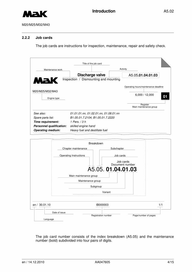
2.2.2 Job cards
The job cards are instructions for inspection, maintenance, repair and safety check.
The job card number consists of the index breakdown (A5.05) and the maintenancenumber (bold) subdivided into four pairs of digits.
¬
Discharge valveInspection / Dismounting and mounting
A5.05.01.04.01.03
6,000 / 12,000M20/M25/M32/M43
01Engine type
Operating hours/maintenance deadline
RegisterMain maintenance group
Title of the job card
ActivityMaintenance work
en / 30.01.10 IB000003 1/1
Language
Date of issue
Registration number Page/number of pages
See also: 01.01.01.nn, 01.02.01.nn, 01.08.01.nn
Spare parts list: B1.05.01.7.2104, B1.05.01.7.2220
Time requirement: 1 Pers. / 3 h
Personnel qualification: skilled engine hand
Operating medium: Heavy fuel and destillate fuel
Job cardsDocument number
Operating Instructions
Chapter maintenance Subchapter
Job cards
Main maintenance group
Maintenance group
Subgroup
Breakdown
A5.05. 01.04.01.03
Variant
en / 14.12.2010 AA047605 4/15
Introduction A5.02
M20/M25/M32/M43
• The first pair of digits indicates the engine main maintenance group:
01. Cylinder head 08. Lube oil system
02. Driving mechanism 09. Cooling water system
03. Engine housing 10. Starting air system
04. Engine control 11. Monitors
05. Regulation 12. Auxiliary generator sets and tools
06. Exhaust gas system/ 13. Additional installationsupercharging
07. Fuel system
In order to facilitate the finding of the engine main group, the pair of digits on the rightmargin has been set as register .
• The second and third pair of digits indicates the subgroups of the main group andthe titles of the job card where maintenance work is required.
• The fourth pair of digits indicates the type of variant.
• See job card: Reference is made to other job cards required for maintenance work.At this point the types of variants (fourth pair of digit) are marked “nn”.
• Spare parts sheets: For easy finding of necessary comsumables and spare parts forthe maintenance group in the Spare parts catalogue, indicating other design detailsin the illustrations, if necessary.
The third pair of digits in the index breakdown in the spare parts number indicates themain group/register.
• Fuel: Documenting the sold type of fuel of the engine plant.
• In the maintenance sheets the checks, maintenance, cleaning and repair works of themaintenance sheets are briefly designated
01
en / 14.12.2010 AA047605 5/15

Introduction A5.02
M20/M25/M32/M43
• Under the designation "tools (W)" only special and additional tools are listed with thetool No. Not all of these tools are included in the normal scope of supply.
• Together with the engine type it will be indicated for what engine the job card is valid.
• The indicated personnel and time requirement does not define the working time ofthe individual person.
• The indicated time is based on estimated mean values which may deviate accordingto the equipment of the plant and its maintenance conditions. Wherever the requiredworking time depends on the number of cylinders the indicated time of the mainte-nance sheets refers to one cylinder unit only.
2.2.3 Maintenance schedule (Periodic maintenance work)
A large-scale plan showing all maintenance work up to the largest maintenance intervalclearly indicating all occurrences and the future work expenditure for the individualcomponents.
It would be useful to mount the plan on a wall; when this is not possible for space rea-sons, it has to be folded and filed in the map “maintenance forms” *.
We cannot and will not give instructions for handling this plan but we will only give yousome guidelines how to use this plan as an aid for the maintenance system.
The work already carried out will be countersigned in fields intended for this purpose.Different colours can be used to differentiate between the results, e.g.: green = nodefects/o.k.; yellow = readjustment/correction (e.g. clearances); red = damage/replace-ment of parts.
Typical consumption parts which are replaced routinely or any time mounting is carriedout (O-ring seals, O-rings etc.) are not considered defective parts.
* The map will be handed during commissioning of the engine
en / 14.12.2010 AA047605 6/15

Introduction A5.02
M20/M25/M32/M43
3. Safety instructions
3.1 Safety symbols
In the present operating instructions the following warning notices are used:
A warning notice of this risk level signals the threat of a dangerous situation.
If the dangerous situation is not prevented, it will lead to death or serious injury.
Follow the instructions in this warning notice to prevent the risk of death or serious injury to persons.
A warning notice of this risk level signals a potentially dangerous situation.
If the dangerous situation is not prevented, this could lead to death or serious injury to persons.
Follow the instructions in this warning notice to prevent the possible risk of death or serious injury to persons.
A warning notice of this risk level signals a potentially dangerous situation.
If the dangerous situation is not prevented, this could lead to minor or moderate injury.
Follow the instructions in this warning notice to prevent injury to persons.
DANGER
WARNING
CAUTION
en / 14.12.2010 AA047605 7/15
Introduction A5.02
M20/M25/M32/M43
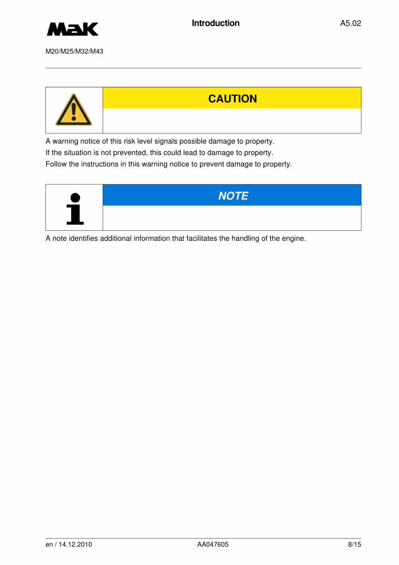
A warning notice of this risk level signals possible damage to property.
If the situation is not prevented, this could lead to damage to property.
Follow the instructions in this warning notice to prevent damage to property.
A note identifies additional information that facilitates the handling of the engine.
CAUTION
NOTE
en / 14.12.2010 AA047605 8/15

Introduction A5.02
M20/M25/M32/M43
3.2 General safety instructions
Our engine is equipped with a monitoring system and an emergency stop system to prevent da-
mage caused to the operators' health as well as damages to the engine.
Within the scope of commissioning all mechanical, electric and pneumatic equipment and sy-
stems allowing the engine to be stopped for safety reasons will be demonstrated and explained
by our commissioning personnel.
Participants in this acceptance procedure are the authorized personnel of Caterpillar Motoren
GmbH & Co. KG, the managing and operating personnel of the operator and also representatives
of the insurance companies.
This important system is subject to recurrent inspections and tests in order to ensure proper
function of its individual components.
In the section "Scheduled Maintenance" you will find the respective test frequencies and related
job instructions that should be followed to protect the personnel from injuries and prevent material
damages.
NOTE
The provisions of the relevant accident prevention regulations of the appro-priate employer's liability insurance association are to be observed any time operation and repair work is carried out.
en / 14.12.2010 AA047605 9/15
Introduction A5.02
M20/M25/M32/M43
WARNING
Keep all handles, steps, handrails, platforms, ladders free from dirt, e.g. oil, grease, fuel!
Use only suitable and technically perfect lifting gear and suspension systems with adequate lifting capacity!
Never work or stand under suspended loads!
During replacement work, individual parts and large assemblies are to be ca-refully fastened and secured on hoists to avoid risks of accidents!
Re-install removed guards and protecting devices on completion of work.
When carrying out overhead assembly work, the specially designed or safe-ty-oriented climbing aids are to be used only!
Do not use engine/plant parts for climbing on!
Use personal protective equipment as far as necessary or as required by the regulations!
Pressurized plant components (lube oil, hydraulic oil, fuel, cooling water, star-ting and control air) must be depressurized. Shut-off valves are to be secured by a plate “Do not open”!
When work is being carried out on engines and systems, the switch-on de-vices have to be switched off and protected. In order to prevent reconnection, the engines and systems have to be marked with a plate “Do not switch” or an appropriate pictogram plate!
Mounting openings are to be protected!
Replaced seals should be disposed of immediately, and above all, it should be taken care that this material is not overheated even by accident e.g. du-ring combustion and welding operations. If this should however has happen-ed, the gases emitted must not be inhaled. Skin contact with decomposed VITONR is to be avoided at all times. After a fire with VITONR, it is essential that neoprene gloves are worn during the clearing up operations.
en / 14.12.2010 AA047605 10/15
Introduction A5.02
M20/M25/M32/M43
CAUTION
Seals made of VITONR have been used at various locations in the engine. With normal engine operation this material is completely harmless, however it should not be exposed to temperatures above 300 °C, since above 325 °C a thermal decomposition and the formation of hydrofluoric acid can occur.
CAUTION
Maintenance and repair work must only be carried out by skilled and autho-rized personnel!
NOTE
Any residues have to be neutralized before their disposal, i.e. saturated with calcium hydroxide.
Clean the engine parts, especially connections and threaded unions of any traces of oil, fuel or preservatives before carrying out maintenance/repair (di-sassembly, assembly)!
Never use aggresive detergents and preservatives!
Use non-fuzzy cleaning rags!
Observe all indicating labels attached to the engine!
en / 14.12.2010 AA047605 11/15
Introduction A5.02
M20/M25/M32/M43
3.3 Working on electrical equipment
CAUTION
Work on the electrical equipment of the engine/plant must be carried out only by a skilled electrician or by instructed persons under the supervision and guidance of a skilled electrician in accordance with the electrical engineering rules and regulations!
Use only original fuses with the specified current raiting! Switch off the engi-ne/plant immediately if trouble occurs in the electrical system!
The electrical equipment is to be inspected/checked at regular intervals. Defects such as loose connections or scorched cables must be rectified imme-diately!
DANGER
Engine or plant parts on which inspection and maintenance work is being car-ried out have to be - if prescribed - shut off at the power supply and provided with the notice “Do not switch on” or the corresponding warning sign!
en / 14.12.2010 AA047605 12/15
Introduction A5.02
M20/M25/M32/M43
3.4 Working with hydraulic devices
3.5 Checking and adjustment of injection valve
WARNING
Do not place parts of your body above/below pressurized hydraulic tools!
Replace hydraulic hose lines at regular intervals, even if no safety relevant defects are detectable!
Operating instructions, tightening torques and setting dimensions specified in the appropriate job card are to be carefully observed!
The minimum bending radius of the high-pressure hoses are to be strictly ob-served!
The hose lines are to be protected against damage caused by external mechanical, thermal or chemical influences!
CAUTION
During testing make sure that no parts of your body are positioned in the area of the fuel jet!
Do not inhale the fuel mist - respiratory mask!
en / 14.12.2010 AA047605 13/15
Introduction A5.02
M20/M25/M32/M43
3.6 Handling of liquid nitrogen or carbon dioxide snow
3.7 Cleansing agents/chemicals
WARNING
When handling liquid nitrogen or carbon dioxide snow, safety shoes, safety gloves and safety glasses are to be worn in order to avoid injuries. Observe protection against cold!
CAUTION
Parts of the skin which have come into contact with liquid nitrogen or carbon dioxide snow must not be rubbed but covered with sterile surgical bandage
NOTE
Use only cleansing agents with a flash point above 65 °C!
Observe instructions for use in accordance with DIN safety data sheet of the regulati-ons for dangerous substances!
Observe the specialist disposal of all cleansing agents and chemicals in accordance with the regulations for dangerous substances!
In case of accident, observe the accident leaflets including first-aid actions for dangerous substances in accordance with the regulations for dangerous substances!
en / 14.12.2010 AA047605 14/15
Introduction A5.02
M20/M25/M32/M43
3.8 Proposition 65 Warning
NOTE
California / USA
Proposition 65 Warning
Diesel engine exhaust and some of its constituents are known to the state of California to cause cancer, birth defects, and other reproductive harm.
en / 14.12.2010 AA047605 15/15
Periodical scheduleDistillate fuel
A5.04.01
M20
Intervall Designation / Doc-Nr.
Work to be carried outRemarks
-------
Daily inspection and monitoring procedures
-------------------------------------------------------------------------------------------------------------------------
(if it is not automated)
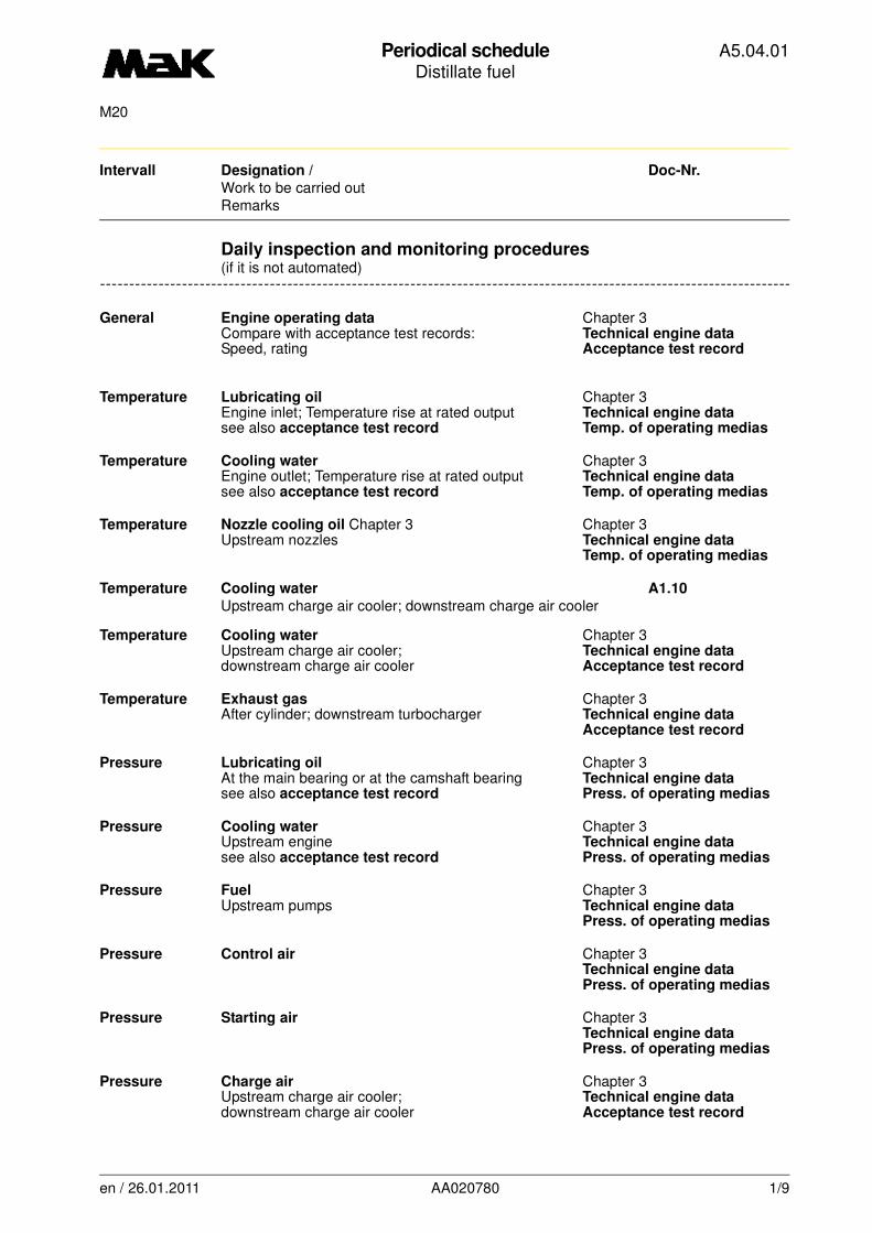
General Engine operating data Chapter 3Compare with acceptance test records: Technical engine dataSpeed, rating Acceptance test record
Temperature Lubricating oil Chapter 3Engine inlet; Temperature rise at rated output Technical engine datasee also acceptance test record Temp. of operating medias
Temperature Cooling water Chapter 3Engine outlet; Temperature rise at rated output Technical engine datasee also acceptance test record Temp. of operating medias
Temperature Nozzle cooling oil Chapter 3 Chapter 3Upstream nozzles Technical engine data
Temp. of operating medias
Temperature Cooling water A1.10
Upstream charge air cooler; downstream charge air cooler
Temperature Cooling water Chapter 3Upstream charge air cooler; Technical engine datadownstream charge air cooler Acceptance test record
Temperature Exhaust gas Chapter 3After cylinder; downstream turbocharger Technical engine data
Acceptance test record
Pressure Lubricating oil Chapter 3At the main bearing or at the camshaft bearing Technical engine datasee also acceptance test record Press. of operating medias
Pressure Cooling water Chapter 3Upstream engine Technical engine datasee also acceptance test record Press. of operating medias
Pressure Fuel Chapter 3Upstream pumps Technical engine data
Press. of operating medias
Pressure Control air Chapter 3Technical engine dataPress. of operating medias
Pressure Starting air Chapter 3Technical engine dataPress. of operating medias
Pressure Charge air Chapter 3Upstream charge air cooler; Technical engine datadownstream charge air cooler Acceptance test record
en / 26.01.2011 AA020780 1/9
Periodical scheduleDistillate fuel
A5.04.01
M20
Intervall Designation / Doc-Nr.
Work to be carried outRemarks
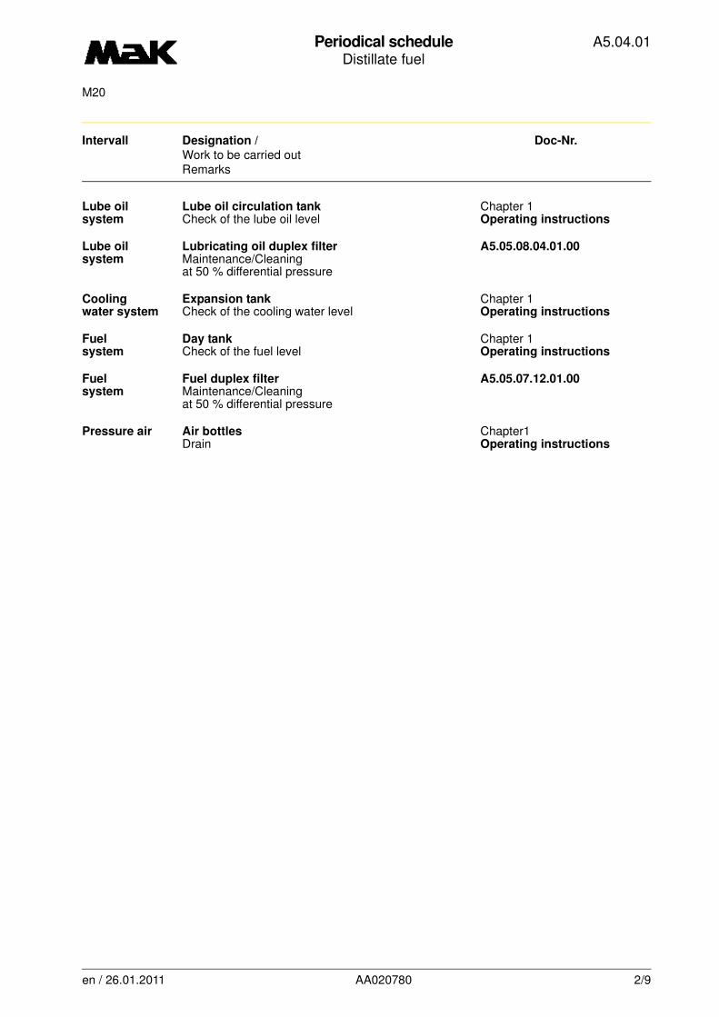
Lube oil Lube oil circulation tank Chapter 1system Check of the lube oil level Operating instructions
Lube oil Lubricating oil duplex filter A5.05.08.04.01.00system Maintenance/Cleaning
at 50 % differential pressure
Cooling Expansion tank Chapter 1water system Check of the cooling water level Operating instructions
Fuel Day tank Chapter 1system Check of the fuel level Operating instructions
Fuel Fuel duplex filter A5.05.07.12.01.00system Maintenance/Cleaning
at 50 % differential pressure
Pressure air Air bottles Chapter1Drain Operating instructions
en / 26.01.2011 AA020780 2/9
Periodical scheduleDistillate fuel
A5.04.01
M20
Intervall Designation / Doc-Nr.
Work to be carried outRemarks
-------
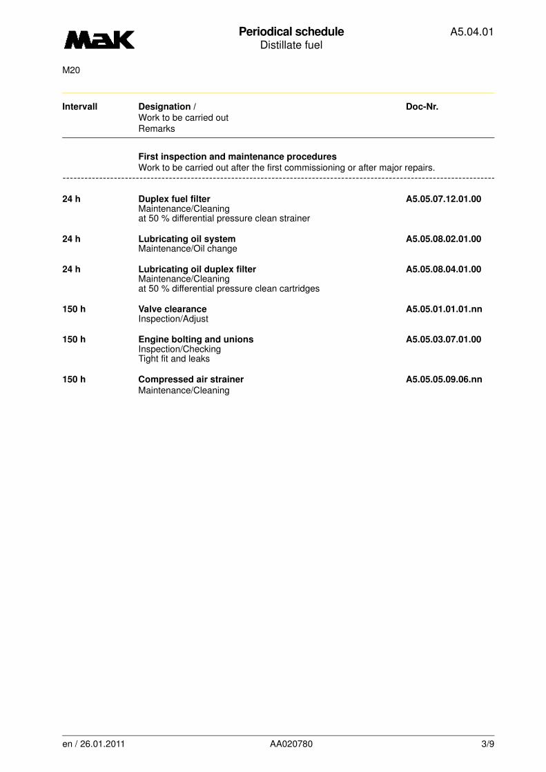
First inspection and maintenance procedures
-------------------------------------------------------------------------------------------------------------------------
Work to be carried out after the first commissioning or after major repairs.
24 h Duplex fuel filter A5.05.07.12.01.00Maintenance/Cleaningat 50 % differential pressure clean strainer
24 h Lubricating oil system A5.05.08.02.01.00Maintenance/Oil change
24 h Lubricating oil duplex filter A5.05.08.04.01.00Maintenance/Cleaningat 50 % differential pressure clean cartridges
150 h Valve clearance A5.05.01.01.01.nnInspection/Adjust
150 h Engine bolting and unions A5.05.03.07.01.00Inspection/CheckingTight fit and leaks
150 h Compressed air strainer A5.05.05.09.06.nn
Maintenance/Cleaning
en / 26.01.2011 AA020780 3/9

Periodical scheduleDistillate fuel
A5.04.01
M20
Intervall Designation / Doc-Nr.
Work to be carried outRemarks
-------
-------------------------------------------------------------------------------------------------------------------------Periodical maintenance procedures
24 h Compressed air strainer A5.05.05.09.06.nn
Maintenance/Cleaning
24 h Turbocharger A5.05.06.05.00.01Maintenance/Cleaningsee book C
150 h Valve rotor A5.05.01.03.01.00Inspection/Evaluate
150 h Cylinder head A5.05.01.10.00.00Inspection/Checkingof all cylinder units
150 h Vorschmierpumpe/Vorschmierung A5.05.08.10.00.00Wartung/Prüfen
300 h Turbocharger A5.05.06.05.00.01Maintenance/Cleaningsee book C
300 h Turbocharger A5.05.06.13.01.nnMaintenance/Cleaningsee book C
750 h Cooling water system A4.05.09.01Inspection/Anti-corrosion oil
750 h Duplex Fuel Filter A5.05.07.12.01.00Maintenance/Cleaning
1.500 h Valve clearance A5.05.01.01.01.nnInspection/Adjust
1.500 h Running gear/Engine timing A5.05.02.01.01.00Inspection/Checking
1.500 h Crankcase explosion safety valve A5.05.03.01.01.nnInspection/Checking
1.500 h Control shaft bedding A5.05.05.01.02.00Maintenance/Checking
1.500 h GovernorGovernor behaviour/Governor control rodsee book C
3.750 h Running gear/Engine timing A5.05.02.01.01.00Inspection/Checking
3.750 h Timing gear train A5.05.04.08.01.00Inspection/Checking
en / 26.01.2011 AA020780 4/9
Periodical scheduleDistillate fuel
A5.04.01
M20
Intervall Designation / Doc-Nr.
Work to be carried outRemarks
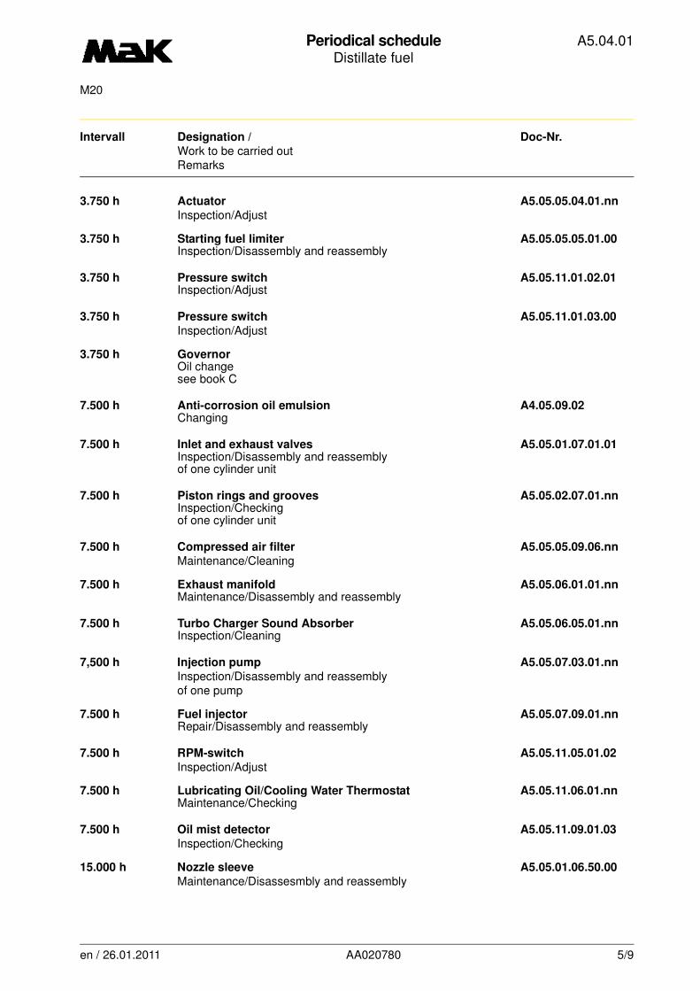
3.750 h Actuator A5.05.05.04.01.nn
Inspection/Adjust
3.750 h Starting fuel limiter A5.05.05.05.01.00Inspection/Disassembly and reassembly
3.750 h Pressure switch A5.05.11.01.02.01Inspection/Adjust
3.750 h Pressure switch A5.05.11.01.03.00
Inspection/Adjust
3.750 h GovernorOil changesee book C
7.500 h Anti-corrosion oil emulsion A4.05.09.02Changing
7.500 h Inlet and exhaust valves A5.05.01.07.01.01Inspection/Disassembly and reassemblyof one cylinder unit
7.500 h Piston rings and grooves A5.05.02.07.01.nnInspection/Checkingof one cylinder unit
7.500 h Compressed air filter A5.05.05.09.06.nn
Maintenance/Cleaning
7.500 h Exhaust manifold A5.05.06.01.01.nnMaintenance/Disassembly and reassembly
7.500 h Turbo Charger Sound Absorber A5.05.06.05.01.nnInspection/Cleaning
7,500 h Injection pump A5.05.07.03.01.nn
Inspection/Disassembly and reassemblyof one pump
7.500 h Fuel injector A5.05.07.09.01.nnRepair/Disassembly and reassembly
7.500 h RPM-switch A5.05.11.05.01.02
Inspection/Adjust
7.500 h Lubricating Oil/Cooling Water Thermostat A5.05.11.06.01.nnMaintenance/Checking
7.500 h Oil mist detector A5.05.11.09.01.03
Inspection/Checking
15.000 h Nozzle sleeve A5.05.01.06.50.00
Maintenance/Disassesmbly and reassembly
en / 26.01.2011 AA020780 5/9

Periodical scheduleDistillate fuel
A5.04.01
M20
Intervall Designation / Doc-Nr.
Work to be carried outRemarks
15.000 h Inlet and exhaust valves A5.05.01.07.01.01Inspection/Disassembly and reassemblyof all inlet and exhaust valves
15.000 h Big-end bearings A5.05.02.04.01.01Inspection/Disassemblyof one big-endbearing
15.000 h Main bearings A5.05.02.05.01.01
Inspection/Disassemblyof two main bearings
15.000 h Governor drive A5.05.04.08.03.00Inspection/Disassembly and reassembly
15.000 h Vibration damper on camshaft A5.05.04.09.01.nn
Repair/Disassembly and reassembly
15.000 h Exhaust gas turbocharger A5.05.06.05.00.01
Maintenance/Cleaning resp. revision of turbochargersee book C
15,000 h Injection pump A5.05.07.03.01.nn
Inspection/Disassembly and reassemblyof all pumps
15.000 h Fuel feed pump A5.05.07.13.01.00Maintenance/Disassembly and reassembly
15.000 h Lub oil pump A5.05.08.03.01.00Inspection/Checking
15,000 h Oil pressure regulating valve A5.05.08.05.01.nn
Maintenance/Adjust
15.000 h Centrifugal cooling water pump A5.05.09.07.01.nnMaintenance/Disassembly and reassembly
30.000 h Valve rocker A5.05.01.02.02.00Maintenance/Disassembly and reassembly
30.000 h Valve guide/Oil scraper ring A5.05.01.05.01.01Inspection/Replaceat all valves
30.000 h Cylinder head A5.05.01.10.01.01
Maintenance/Cleaning
30.000 h Big-end bearings A5.05.02.04.01.01Inspection/Disassemblyexchange all big-end bearings
30.000 h Main bearings A5.05.02.05.01.01Inspection/Disassemblyexchange of all bearings
en / 26.01.2011 AA020780 6/9
Periodical scheduleDistillate fuel
A5.04.01
M20
Intervall Designation / Doc-Nr.
Work to be carried outRemarks
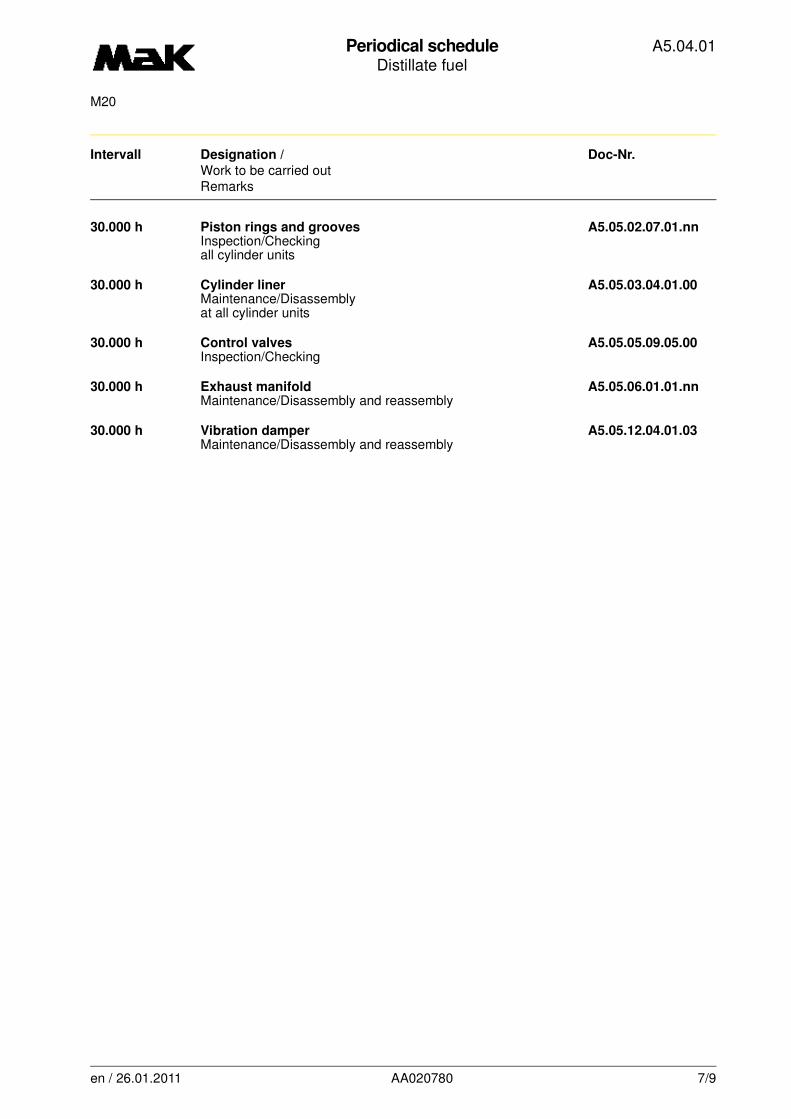
30.000 h Piston rings and grooves A5.05.02.07.01.nnInspection/Checkingall cylinder units
30.000 h Cylinder liner A5.05.03.04.01.00Maintenance/Disassemblyat all cylinder units
30.000 h Control valves A5.05.05.09.05.00Inspection/Checking
30.000 h Exhaust manifold A5.05.06.01.01.nnMaintenance/Disassembly and reassembly
30.000 h Vibration damper A5.05.12.04.01.03Maintenance/Disassembly and reassembly
en / 26.01.2011 AA020780 7/9
Periodical scheduleDistillate fuel
A5.04.01
M20
Intervall Designation / Doc-Nr.
Work to be carried outRemarks
-------
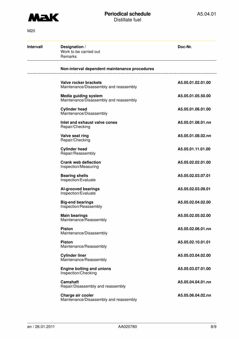
-------------------------------------------------------------------------------------------------------------------------Non-interval dependent maintenance procedures
Valve rocker brackets A5.05.01.02.01.00Maintenance/Disassembly and reassembly
Media guiding system A5.05.01.05.50.00Maintenance/Disassembly and reassembly
Cylinder head A5.05.01.06.01.00Maintenance/Disassembly
Inlet and exhaust valve cones A5.05.01.08.01.nnRepair/Checking
Valve seat ring A5.05.01.08.02.nnRepair/Checking
Cylinder head A5.05.01.11.01.00Repair/Reassembly
Crank web deflection A5.05.02.02.01.00Inspection/Measuring
Bearing shells A5.05.02.03.07.01Inspection/Evaluate
Al-grooved bearings A5.05.02.03.09.01Inspection/Evaluate
Big-end bearings A5.05.02.04.02.00Inspection/Reassembly
Main bearings A5.05.02.05.02.00Maintenance/Reassembly
Piston A5.05.02.06.01.nnMaintenance/Disassembly
Piston A5.05.02.10.01.01Maintenance/Reassembly
Cylinder liner A5.05.03.04.02.00Maintenance/Reassembly
Engine bolting and unions A5.05.03.07.01.00Inspection/Checking
Camshaft A5.05.04.04.01.nnRepair/Disassembly and reassembly
Charge air cooler A5.05.06.04.02.nnMaintenance/Disassembly and reassembly
en / 26.01.2011 AA020780 8/9

Periodical scheduleDistillate fuel
A5.04.01
M20
Intervall Designation / Doc-Nr.
Work to be carried outRemarks
Turbocharger A5.05.06.05.00.01Maintenance/Cleaningsee book C
Injection pump A5.05.07.02.01.nnRepair/Disassembly and reassembly
Injection pump A5.05.07.03.01.nnMaintenance/Disassembly and reassembly
Fuel injector A5.05.07.07.01.nnMaintenance/Disassembly and reassembly
Fuel injector A5.05.07.08.01.nnMaintenance/Adjust
Duplex fuel filter A5.05.07.12.01.00Maintenance/Cleaning
Fuel Distributor Line/Manifold Line A5.05.07.15.01.nnRepair/Disassembly and reassembly
Lubricating oil system A5.05.08.02.01.00Maintenance/oil change
Lub oil pump A5.05.08.03.02.00Maintenance/Disassembly and reassembly
Lubricating oil duplex filter A5.05.08.04.01.00Maintenance/Cleaning
en / 26.01.2011 AA020780 9/9
Periodical scheduleHeavy fuel
A5.04.02
M20
Intervall Designation / Doc-Nr.
Work to be carried outRemarks
-------
Daily inspection and monitoring procedures
-------------------------------------------------------------------------------------------------------------------------
(if it is not automated)
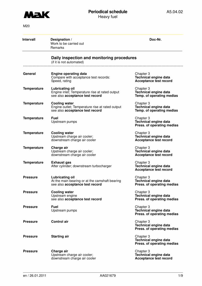
General Engine operating data Chapter 3Compare with acceptance test records: Technical engine dataSpeed, rating Acceptance test record
Temperature Lubricating oil Chapter 3Engine inlet; Temperature rise at rated output Technical engine datasee also acceptance test record Temp. of operating medias
Temperature Cooling water Chapter 3Engine outlet; Temperature rise at rated output Technical engine datasee also acceptance test record Temp. of operating medias
Temperature Fuel Chapter 3Upstream pumps Technical engine data
Press. of operating medias
Temperature Cooling water Chapter 3Upstream charge air cooler; Technical engine datadownstream charge air cooler Acceptance test record
Temperature Charge air Chapter 3Upstream charge air cooler; Technical engine datadownstream charge air cooler Acceptance test record
Temperature Exhaust gas Chapter 3After cylinder; downstream turbocharger Technical engine data
Acceptance test record
Pressure Lubricating oil Chapter 3At the main bearing or at the camshaft bearing Technical engine datasee also acceptance test record Press. of operating medias
Pressure Cooling water Chapter 3Upstream engine Technical engine datasee also acceptance test record Press. of operating medias
Pressure Fuel Chapter 3Upstream pumps Technical engine data
Press. of operating medias
Pressure Control air Chapter 3Technical engine dataPress. of operating medias
Pressure Starting air Chapter 3Technical engine dataPress. of operating medias
Pressure Charge air Chapter 3Upstream charge air cooler; Technical engine datadownstream charge air cooler Acceptance test record
en / 26.01.2011 AA021679 1/9
Periodical scheduleHeavy fuel
A5.04.02
M20
Intervall Designation / Doc-Nr.
Work to be carried outRemarks
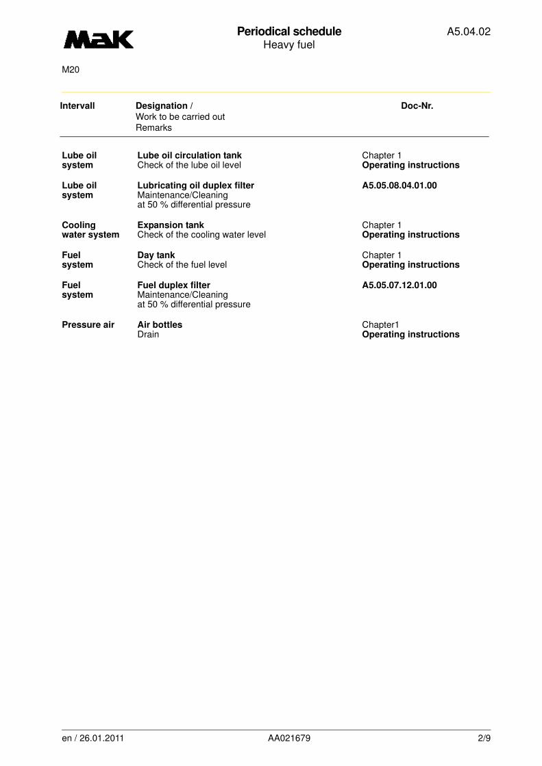
Lube oil Lube oil circulation tank Chapter 1system Check of the lube oil level Operating instructions
Lube oil Lubricating oil duplex filter A5.05.08.04.01.00system Maintenance/Cleaning
at 50 % differential pressure
Cooling Expansion tank Chapter 1water system Check of the cooling water level Operating instructions
Fuel Day tank Chapter 1system Check of the fuel level Operating instructions
Fuel Fuel duplex filter A5.05.07.12.01.00system Maintenance/Cleaning
at 50 % differential pressure
Pressure air Air bottles Chapter1Drain Operating instructions
en / 26.01.2011 AA021679 2/9

Periodical scheduleHeavy fuel
A5.04.02
M20
Intervall Designation / Doc-Nr.
Work to be carried outRemarks
-------
First inspection and maintenance procedures
-------------------------------------------------------------------------------------------------------------------------
Work to be carried out after the first commissioning or after major repairs
24 h Duplex fuel filter A5.05.07.12.01.00
Maintenance/Cleaningat 50 % differential pressure clean strainer
24 h Lubricating oil system A5.05.08.02.01.00
Maintenance/Oil change
24 h Lubricating oil duplex filter A5.05.08.04.01.00
Maintenance/Cleaningat 50 % differential pressure clean cartridges
150 h Valve clearance A5.05.01.01.01.nn
Inspection/Adjust
150 h Engine bolting and unions A5.05.03.07.01.00
Inspection/CheckingTight fit and leaks
en / 26.01.2011 AA021679 3/9

Periodical scheduleHeavy fuel
A5.04.02
M20
Intervall Designation / Doc-Nr.
Work to be carried outRemarks
-------
-------------------------------------------------------------------------------------------------------------------------Periodical maintenance procedures
24 h Compressed air strainer A5.05.05.09.06.nn
Maintenance/Cleaning
24 h Turbocharger A5.05.06.05.00.01
Maintenance/Cleaningsee book C
150 h Valve rotor A5.05.01.03.01.00
Inspection/Evaluate
150 h Cylinder head A5.05.01.10.00.00
Inspection/Checkingof all cylinder units
150 h Prelubricating pump/Prelubrication A5.05.08.10.00.00
Maintenance/Checking
300 h Turbocharger A5.05.06.05.00.01
Maintenance/Cleaningsee book C
300 h Turbocharger A5.05.06.13.01.nn
Maintenance/Cleaning
750 h Cooling water system A4.05.09.01
Inspection/Anti-corrosion oil
750 h Duplex fuel prefilter A5.05.07.12.02.nn
Maintenance/Cleaning
750 h Oil mist detector A5.05.11.09.01.03
Inspection/Checking
1.500 h Valve clearance A5.05.01.01.01.nn
Inspection/Adjust
1.500 h Running gear/Engine timing A5.05.02.01.01.00
Inspection/Checking
1.500 h Crankcase explosion safety valve A5.05.03.01.01.nn
Inspection/Checking
1.500 h Control shaft bedding A5.05.05.01.02.00
Maintenance/Checking
1.500 h Kurbelraumüberwachungsgerät A5.05.11.09.01.03Kontrolle/Prüfen
1.500 h Governor
Governor behaviour/Governor control rodsee book C
3.750h Running gear/Engine timing A5.05.02.01.01.00
Inspection/Checking
en / 26.01.2011 AA021679 4/9
Periodical scheduleHeavy fuel
A5.04.02
M20
Intervall Designation / Doc-Nr.
Work to be carried outRemarks
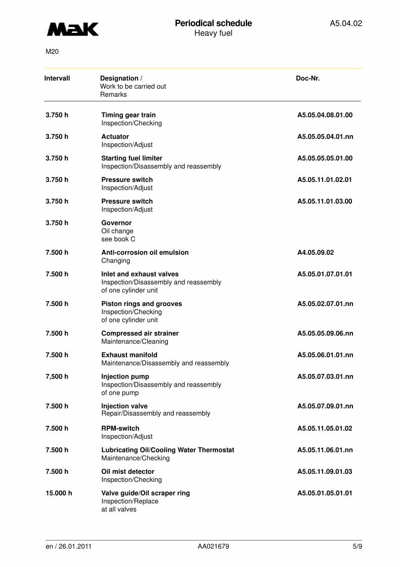
3.750 h Timing gear train A5.05.04.08.01.00
Inspection/Checking
3.750 h Actuator A5.05.05.04.01.nn
Inspection/Adjust
3.750 h Starting fuel limiter A5.05.05.05.01.00
Inspection/Disassembly and reassembly
3.750 h Pressure switch A5.05.11.01.02.01
Inspection/Adjust
3.750 h Pressure switch A5.05.11.01.03.00
Inspection/Adjust
3.750 h Governor
Oil changesee book C
7.500 h Anti-corrosion oil emulsion A4.05.09.02
Changing
7.500 h Inlet and exhaust valves A5.05.01.07.01.01
Inspection/Disassembly and reassemblyof one cylinder unit
7.500 h Piston rings and grooves A5.05.02.07.01.nn
Inspection/Checkingof one cylinder unit
7.500 h Compressed air strainer A5.05.05.09.06.nn
Maintenance/Cleaning
7.500 h Exhaust manifold A5.05.06.01.01.nn
Maintenance/Disassembly and reassembly
7,500 h Injection pump A5.05.07.03.01.nn
Inspection/Disassembly and reassemblyof one pump
7.500 h Injection valve A5.05.07.09.01.nnRepair/Disassembly and reassembly
7.500 h RPM-switch A5.05.11.05.01.02
Inspection/Adjust
7.500 h Lubricating Oil/Cooling Water Thermostat A5.05.11.06.01.nn
Maintenance/Checking
7.500 h Oil mist detector A5.05.11.09.01.03
Inspection/Checking
15.000 h Valve guide/Oil scraper ring A5.05.01.05.01.01
Inspection/Replaceat all valves
en / 26.01.2011 AA021679 5/9
Periodical scheduleHeavy fuel
A5.04.02
M20
Intervall Designation / Doc-Nr.
Work to be carried outRemarks
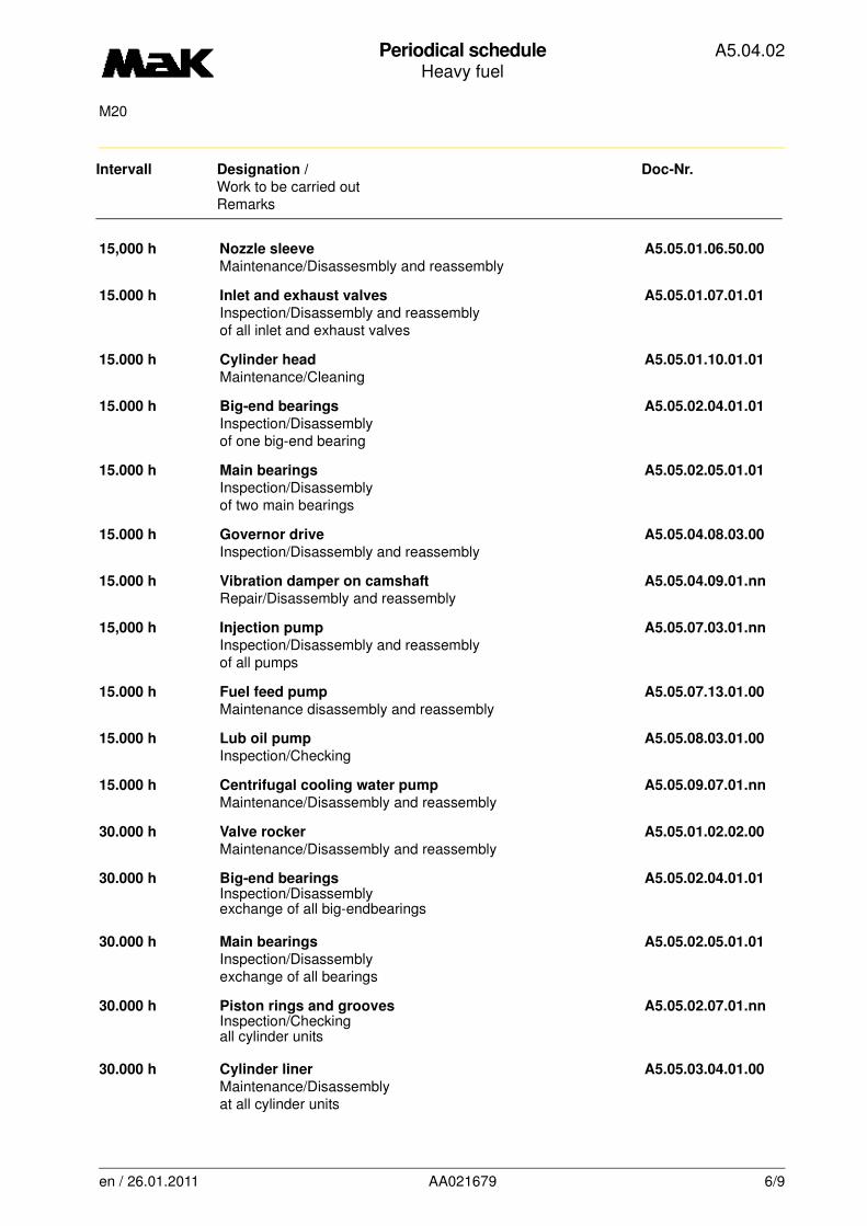
15,000 h Nozzle sleeve A5.05.01.06.50.00
Maintenance/Disassesmbly and reassembly
15.000 h Inlet and exhaust valves A5.05.01.07.01.01
Inspection/Disassembly and reassemblyof all inlet and exhaust valves
15.000 h Cylinder head A5.05.01.10.01.01
Maintenance/Cleaning
15.000 h Big-end bearings A5.05.02.04.01.01
Inspection/Disassemblyof one big-end bearing
15.000 h Main bearings A5.05.02.05.01.01
Inspection/Disassemblyof two main bearings
15.000 h Governor drive A5.05.04.08.03.00
Inspection/Disassembly and reassembly
15.000 h Vibration damper on camshaft A5.05.04.09.01.nn
Repair/Disassembly and reassembly
15,000 h Injection pump A5.05.07.03.01.nn
Inspection/Disassembly and reassemblyof all pumps
15.000 h Fuel feed pump A5.05.07.13.01.00
Maintenance disassembly and reassembly
15.000 h Lub oil pump A5.05.08.03.01.00
Inspection/Checking
15.000 h Centrifugal cooling water pump A5.05.09.07.01.nn
Maintenance/Disassembly and reassembly
30.000 h Valve rocker A5.05.01.02.02.00
Maintenance/Disassembly and reassembly
30.000 h Big-end bearings A5.05.02.04.01.01Inspection/Disassemblyexchange of all big-endbearings
30.000 h Main bearings A5.05.02.05.01.01
Inspection/Disassemblyexchange of all bearings
30.000 h Piston rings and grooves A5.05.02.07.01.nnInspection/Checkingall cylinder units
30.000 h Cylinder liner A5.05.03.04.01.00
Maintenance/Disassemblyat all cylinder units
en / 26.01.2011 AA021679 6/9
Periodical scheduleHeavy fuel
A5.04.02
M20
Intervall Designation / Doc-Nr.
Work to be carried outRemarks
30.000 h Control valves A5.05.05.09.05.00
Inspection/Checking
30.000 h Exhaust manifold A5.05.06.01.01.nn
Maintenance/Disassembly and reassembly
30.000 h Vibration damper A5.05.12.04.01.03
Maintenance/Disassembly and reassembly
en / 26.01.2011 AA021679 7/9
Periodical scheduleHeavy fuel
A5.04.02
M20
Intervall Designation / Doc-Nr.
Work to be carried outRemarks
-------
-------------------------------------------------------------------------------------------------------------------------Non-interval dependent maintenance procedures
Valve rocker brackets A5.05.01.02.01.00
Maintenance/Disassembly and reassembly
Media guiding system A5.05.01.05.50.00Maintenance/Disassembly and reassembly
Cylinder head A5.05.01.06.01.00
Maintenance/Disassembly
Inlet and exhaust valve cones A5.05.01.08.01.nn
Repair/Checking
Valve seat ring A5.05.01.08.02.nn
Repair/Checking
Cylinder head A5.05.01.11.01.00
Repair/Reassembly
Crank web deflection A5.05.02.02.01.00
Inspection/Measuring
Bearing shells A5.05.02.03.07.01
Inspection/Evaluate
Al-grooved bearings A5.05.02.03.09.01
Inspection/Evaluate
Big-end bearings A5.05.02.04.02.00
Inspection/Reassembly
Main bearings A5.05.02.05.02.00
Maintenance/Reassembly
Piston A5.05.02.06.01.nn
Maintenance/Disassembly
Piston A5.05.02.10.01.01
Wartung/Montage
Cylinder liner A5.05.03.04.02.00
Maintenance/Reassembly
Engine bolting and unions A5.05.03.07.01.00
Inspection/Checking
Camshaft A5.05.04.04.01.nn
Repair/Disassembly and reassembly
Actuator A5.05.05.04.01.nn
Maintenance/Disassembly and reassembly
Charge air cooler A5.05.06.04.02.nn
Maintenance/disassembly and reassembly
en / 26.01.2011 AA021679 8/9

Periodical scheduleHeavy fuel
A5.04.02
M20
Intervall Designation / Doc-Nr.
Work to be carried outRemarks
Injection pump A5.05.07.02.01.nn
Repair/Disassembly and reassembly
Injection pump A5.05.07.02.01.nnRepair/Disassembly and reassembly
Injection pump A5.05.07.03.01.nn
Maintenance/Disassembly and reassembly
Injection valve A5.05.07.07.01.nn
Maintenance/Disassembly and reassembly
Injection valve A5.05.07.08.01.nn
Maintenance/Adjust
Duplex fuel filter A5.05.07.12.01.00
Maintenance/Cleaning
Fuel Distributor Line/Manifold Line A5.05.07.15.01.nn
Repair/Disassembly and reassembly
Lubricating oil system A5.05.08.02.01.00
Maintenance/oil change
Lub oil pump A5.05.08.03.02.00
Maintenance/Disassembly and reassembly
Lubricating oil duplex filter A5.05.08.04.01.00
Maintenance/Cleaning
en / 26.01.2011 AA021679 9/9
Valve ClearanceInspection / Adjust
A5.05. 01.01.01.00
1500M20
01
-------
See also: 02.01.01.nn
Spare parts list: B1.05.01.2.2107
Time requirement: 1 Pers./ 0,50 h
Personnel qualification: skilled engine hand
-------------------------------------------------------------------------------------------------------------------------
Operating medium: Heavy fuel and distillate fuel
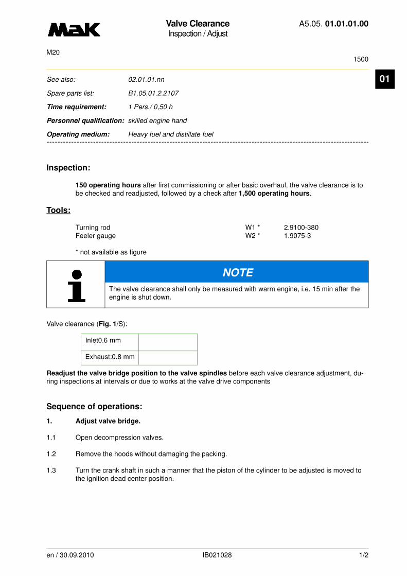
Inspection:
150 operating hours after first commissioning or after basic overhaul, the valve clearance is to be checked and readjusted, followed by a check after 1,500 operating hours.
Tools:
Turning rod W1 * 2.9100-380Feeler gauge W2 * 1.9075-3
* not available as figure
Valve clearance (Fig. 1/S):
Inlet0.6 mm
Exhaust:0.8 mm
Readjust the valve bridge position to the valve spindles before each valve clearance adjustment, du-ring inspections at intervals or due to works at the valve drive components
Sequence of operations:
1. Adjust valve bridge.
1.1 Open decompression valves.
1.2 Remove the hoods without damaging the packing.
1.3 Turn the crank shaft in such a manner that the piston of the cylinder to be adjusted is moved to the ignition dead center position.
NOTE
The valve clearance shall only be measured with warm engine, i.e. 15 min after the engine is shut down.
en / 30.09.2010 IB021028 1/2
Valve ClearanceInspection / Adjust
A5.05. 01.01.01.00
1500M20
01
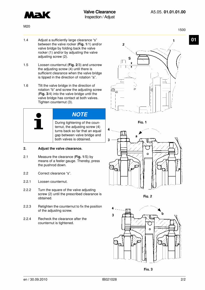
1.4 Adjust a sufficiently large clearance “s” between the valve rocker (Fig. 1/1) and/or valve bridge by folding back the valve rocker (1) and/or by adjusting the valve adjusting screw (2).1.5 Loosen counternut (Fig. 2/3) and unscrew the adjusting screw (4) until there is sufficient clearance when the valve bridge is tipped in the direction of rotation “a”.
1.6 Tilt the valve bridge in the direction of rotation “b” and screw the adjusting screw (Fig. 3/4) into the valve bridge until the valve bridge has contact at both valves. Tighten counternut (3).
2. Adjust the valve clearance.
2.1 Measure the clearance (Fig. 1/S) by means of a feeler gauge. Thereby, press the pushrod down.
2.2 Correct clearance “s”.
2.2.1 Loosen counternut.
2.2.2 Turn the square of the valve adjusting screw (2) until the prescribed clearance is obtained.
2.2.3 Retighten the counternut to fix the position of the adjusting screw.
2.2.4 Recheck the clearance after the counternut is tightened.
NOTE
During tightening of the coun-ternut, the adjusting screw (4) turns back so far that an equal gap between valve bridge and both valves is obtained.
en / 30.09.2010 IB021028 2/2
Valve clearanceInspection / Adjust
A5.05. 01.01.01.02
1500M20
01
-------
See also: 02.01.01.nn
Spare parts list: B1.05.01.2.2107
Time requirement: 1 Pers./ 0,50 h
Personnel qualification: skilled engine hand
-------------------------------------------------------------------------------------------------------------------------
Operating medium: Heavy fuel and distillate fuel
Inspection:
Check valve clearance,adjust if necessary every 1.500 h
Tools:
Feeler gauge W1 * 1.9075-003Turning rod W2 * 2.9100-380* not illustrated
Sequence of operations:
1. Adjust valve bridge.
1.1 Open the decompression valve.
1.2 Remove the cylinder head covers.
1.3 Move the cylinder to be adjusted to firing TDC. Inlet and exhaust valves are closed, rocker arm relieved.
1.4 Release valve bridge (1) of rocker arm (5). Enlarge clearance „s“ and/or flap back rocker arm (5).
NOTE
The valve clearance should only be measured when the engine is warm, i.e. 15 min. after the engine is shut down.
The position of the valve bridge must be readjusted before adjusting the valve clearance during scheduled inspections or due to work being carried out on the valve drive components.
NOTE
The adjustment is necessary so that the clearance “s“ of the valve bridge (Fig.1/1) is distributed evenly onto the corresponding valve cones (2,3).There must be a sufficient clearance ”s” between the valve adjusting screw (4) and the valve bridge (1) when adjusting the valve bridge.
en / 30.09.2010 IB025384 1/2

Valve clearanceInspection / Adjust
A5.05. 01.01.01.02
1500M20
01
1.5 Release locknut (6) and unsrew setting bolt (7) until a contact in „X”without clearance is reached.
1.6 At this position of the valve bridge screw in setting bolt (7) until contact at „Y” without any clearance is reached.Valve bridge must not be tited.
1.7 Hold tight setting bolt (7) and tighten lock-nut (6) with
M = 30 Nm.
1.8 Check absence of clearance at „X“ and „Y“ with feeler gauge of 0.02 mm (W1). Afterwards adjust valve clearance „s“ as per instruction.
2. Adjust valve clearance
2.1 Press the rocker arm (5) onto the push rod and measure the clearance „s“ with the feeler gauge.
2.2 Correct the clearance “s”:
2.2.1 Loosen counter nut (8).
2.2.2 Turn the valve adjusting screws (4) until the specified clearance ”s” has been attained.
Valve clearance „s“:
Inlet: 0.6 mm
Outlet: 0.8 mm
2.2.3 Tighten counter nut (8) with
M = 90 Nm
2.2.4 Check the clearance ”s” again.
2.3 Check the gaskets for the cylinder cover hoods and mount the cylinder cover hood.
2.4 Remove turning rod
2.5 Close decompression valves.
en / 30.09.2010 IB025384 2/2
Valve Rocker BracketsMaintenance / Disassembly and reassembly
A5.05. 01.02.01.00
M20
01
-------
See also: 01.01.01.nn
Spare parts list: B1.05.01.2.2107
Time requirement: 1 Pers./ 0,20 h
Personnel qualification: skilled engine hand
-------------------------------------------------------------------------------------------------------------------------
Operating medium: Heavy fuel and distillate fuel
Tools:
Torque wrench 40 - 180 Nm 1/2" W1 * 1.9454-40Turning rod W2 * 2.9100-380
* not available as figure
Auxiliary material:
Molykote paste “G-Rapid Plus” **
** or a product of equal standard
Sequence of operations:
1. Disassembly
1.1 Remove the cylinder head cover.
1.2 Move the piston to firing TDC. Inlet valves and exhaust valves are closed, valve rocker is relieved.
1.3 Unscrew the nuts (Fig. 1/1 and 2).
1.4 Remove the valve rocker bracket with inlet rocker and exhaust rocker.
2. Reassembly
2.1 Clean the surface for the valve rocker bracket on the cylinder head.
2.2 Blow through the oil transition hole with compressed air.
2.3 Fit the valve rocker bracket via studs on the cylinder head and adjust in such a way that the adjusting screws rest on the center of the valve bridges.
en / 30.09.2010 IB001341 1/2

Valve Rocker BracketsMaintenance / Disassembly and reassembly
A5.05. 01.02.01.00
M20
01
2.4 Grease the thread and nut contact face with Molykote paste “G-Rapid Plus” and tighten the nuts gradually (1) with aTorque of 120 Nm
and nuts (2) with a
Torque of 60 Nm.
2.5 Set the valve clearance (01.01.01 nn).
2.6 Perform the oil flow control.
2.7 Fit the cylinder head cover (inspect the gasket).
en / 30.09.2010 IB001341 2/2
Valve RockerMaintenance / Disassembly and reassembly
A5.05. 01.02.02.00
30000M20
01
-------
See also: 01.02.01.nn
Spare parts list: B1.05.01.2.2107
Time requirement: 1 Pers./ 1,00 h
Personnel qualification: skilled engine hand
-------------------------------------------------------------------------------------------------------------------------
Operating medium: Heavy fuel and distillate fuel
Maintenance:
Disassemble inlet and exhaust valve rocker and inspect the bearing clearances 30,000 h
Sequence of operations:
1. Disassembly
1.1 Disassemble valve rocker bracket (01.02.01.nn).
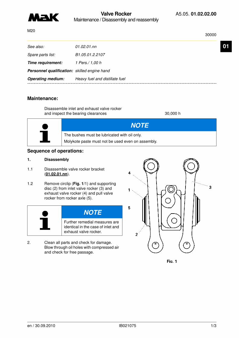
1.2 Remove circlip (Fig. 1/1) and supporting disc (2) from inlet valve rocker (3) and exhaust valve rocker (4) and pull valve rocker from rocker axle (5).
2. Clean all parts and check for damage. Blow through oil holes with compressed air and check for free passage.
NOTE
The bushes must be lubricated with oil only.
Molykote paste must not be used even on assembly.
NOTE
Further remedial measures are identical in the case of inlet and exhaust valve rocker.
en / 30.09.2010 IB021075 1/3
Valve RockerMaintenance / Disassembly and reassembly
A5.05. 01.02.02.00
30000M20
01
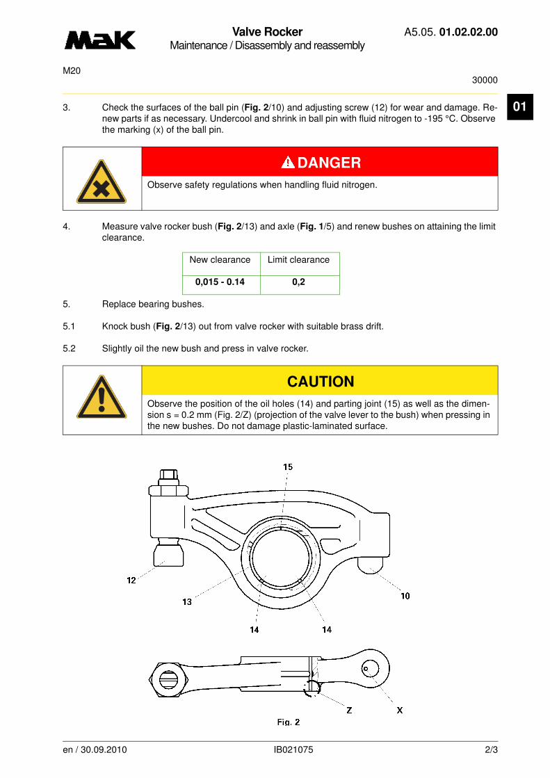
3. Check the surfaces of the ball pin (Fig. 2/10) and adjusting screw (12) for wear and damage. Re-new parts if as necessary. Undercool and shrink in ball pin with fluid nitrogen to -195 °C. Observe the marking (x) of the ball pin.4. Measure valve rocker bush (Fig. 2/13) and axle (Fig. 1/5) and renew bushes on attaining the limit clearance.
New clearance Limit clearance
0,015 - 0.14 0,2
5. Replace bearing bushes.
5.1 Knock bush (Fig. 2/13) out from valve rocker with suitable brass drift.
5.2 Slightly oil the new bush and press in valve rocker.
DANGER
Observe safety regulations when handling fluid nitrogen.
CAUTION
Observe the position of the oil holes (14) and parting joint (15) as well as the dimen-sion s = 0.2 mm (Fig. 2/Z) (projection of the valve lever to the bush) when pressing in the new bushes. Do not damage plastic-laminated surface.
en / 30.09.2010 IB021075 2/3

Valve RockerMaintenance / Disassembly and reassembly
A5.05. 01.02.02.00
30000M20
01
6. Reassembly6.1 Oil surfaces of the bushes of the inlet val-ve rocker (Fig. 1/3) and exhaust valve rok-ker (4) and rocker axle and carefully move the valve rocker onto the axle. Do not tilt valve rocker.
6.2 Fix the valve rocker with supporting disc (2) and circlip (1) axially.
6.3 Mount the valve rocker bracket on the cy-linder head (01.02.01.nn) and carry out lube oil flow control.
NOTE
Valve rocker axle must be un-damaged and free of burrs.
en / 30.09.2010 IB021075 3/3

Valve RotatorInspection / Evaluate
A5.05. 01.03.01.00
150M20
en / 24.09.2010 IB000333 1/1
01See also: 01.07.01.nn, 01.10.00.nn
Spare parts list: B1.05.01.2.2107
Time requirement: 1 Pers./ 0,10 h
Personnel qualification: skilled engine hand
--------------------------------------------------------------------------------------------------------------------------------
Operating medium: Heavy fuel and distillate fuel
Inspection:
of the valve rotator every 150 h
Sequence of operations:
1. Check valve rotation.
2. The valve rotator works properly if a uniform and engine speed dependent rotation can be detec-ted.
3. Lubricate the valve rotator with some drops of lubricating oil/gas oil mixture (mixture ratio 1:1) if a considerable deceleration of rotation, is detected in comparison to the new condition.
3.1 If, at nominal engine speed, the rotational speed goes down to approx 1 rpm, the valve rotator has to be changed.
CAUTION
Heavy fuel operation:=4 valve rotatorsinlet and exhaust valvesDistillate fuel operation:=2 valve rotatorsinlet valves only
NOTE
Check the rotational speed of the valves versus engine speed immediately after star-ting a new engine or when a plant has been overhauled. Use this rotational speed for reference later.
NOTE
Deceleration of the valve rotation can also be caused by hard motion of the valve stem in the valve guide. Remedy: Inject the gas oil/lubricating oil mixture drop by drop onto the valve stem.
CAUTION
Do not apply too much lubricating oil/gas oil mixture. There is danger of lubricating oil dilution!

Valve Guide / Oil Scraper RingInspection / Replacement
A5.05. 01.05.01.01
15000M20
01
-------
See also: 01.01.01.nn, 01.02.01.nn, 01.06.01.nn, 01.07.01.nn
Spare parts list: B1.05.01.2.2107
Time requirement: 1 Pers./ 0,20 h
Personnel qualification: skilled engine hand
-------------------------------------------------------------------------------------------------------------------------
Operating medium: Heavy fuel
Inspection:
of valve guide clearance of inlet and exhaust valves after 15,000 h
Auxiliary material:
Molykote paste “G-Rapid Plus” **
** or a product of equal standard
Sequence of operations:
1. Replacement of the oil scraper rings
(O-rings)
1.1 Dismount valve face, thoroughly clean stem.
1.2 Remove the O-ring (Fig. 1/1) from the groove of the guide bush by means of a sharp angle-shaped wire.
1.3 Clean the groove.
1.4 Slightly oil the new O-ring and carefully insert the O-ring in the groove. The ring must not be twisted in mounting position.
CAUTION
The O-ring is used to adjust the lubricant quantity and must only be replaced by a new original MaK spare part.
en / 31.05.2010 IB021186 1/2
Valve Guide / Oil Scraper RingInspection / Replacement
A5.05. 01.05.01.01
15000M20
01
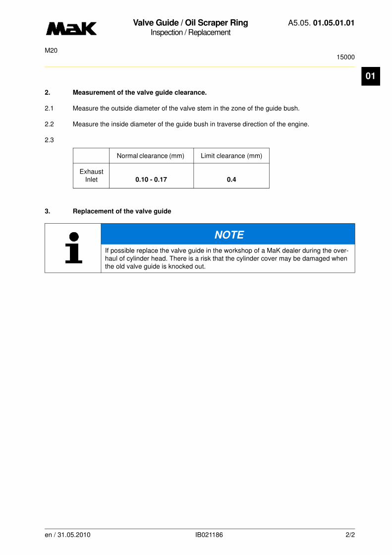
2. Measurement of the valve guide clearance.
2.1 Measure the outside diameter of the valve stem in the zone of the guide bush.
2.2 Measure the inside diameter of the guide bush in traverse direction of the engine.
2.3
Normal clearance (mm) Limit clearance (mm)
ExhaustInlet 0.10 - 0.17 0.4
3. Replacement of the valve guide
NOTE
If possible replace the valve guide in the workshop of a MaK dealer during the over-haul of cylinder head. There is a risk that the cylinder cover may be damaged when the old valve guide is knocked out.
en / 31.05.2010 IB021186 2/2

Media lineMaintenance / Disassembly and reassembly
A5.05. 01.05.50.00
M20
01
-------
See also:
Spare parts list: B1.05.01.2.2144
Time requirement: 1 Pers./ 0,25 h
Personnel qualification: skilled engine hand
-------------------------------------------------------------------------------------------------------------------------
Operating medium: Heavy fuel and distillate fuel
Auxiliary material:soft green soap*
* or product of equal standard
Sequence of operations:
1. Disassembly
1.1 Disassemble lubricating oil line for the injection pump (fig. 1/1) at the flange (3b) of the media li-ne.
1.2 Remove cheese head screws (2).
CAUTION
Depressurize system before commencing work.
A
2
B
A
B
2 4
Z
1
6
7
3b1
5
3a
en / 31.05.2010 IB003153 1/3

Media lineMaintenance / Disassembly and reassembly
A5.05. 01.05.50.00
M20
01
1.3 Remove flange (3a and 3b) together with sleeves (4).1.4 Remove sleeves (4) from flanges (3a and 3b).
1.5 Check O-rings (fig. 2/12) and, if necessary, insert new O-rings untwisted in the grooves using
soft soap.
1.6 Remove seals (11) and clean sealing surfaces.
2. Assembly
2.1 Mount sleeves (fig. 2/4) with flanges (3a and 3b).
2.2 Replace seals (fig. 3/11) (centering by dowel pins 21).
2.3 Mount flanges, seals and sleeves with cheese head screws.
4
11
12
3b
11
3a
A-A
2
21X
11
X
B-B
3
11
en / 31.05.2010 IB003153 2/3
Media lineMaintenance / Disassembly and reassembly
A5.05. 01.05.50.00
M20
01
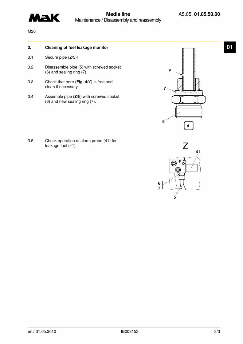
3. Cleaning of fuel leakage monitor3.1 Secure pipe (Z/5)!
3.2 Disassemble pipe (5) with screwed socket (6) and sealing ring (7).
3.3 Check that bore (Fig. 4/Y) is free and clean if necessary.
3.4 Assemble pipe (Z/5) with screwed socket (6) and new sealing ring (7).
3.5 Check operation of alarm probe (41) for leakage fuel (41).
7
6
44
Y
41
Z
5
6
7
en / 31.05.2010 IB003153 3/3

Cylinder HeadMaintenance / Disassembly
A5.05. 01.06.01.00
M20
01
-------
See also:
Spare parts list:
Time requirement: 1 Pers./ 0,50 h
Personnel qualification: skilled engine hand
-------------------------------------------------------------------------------------------------------------------------
Operating medium: Heavy fuel and distillate fuel
Tools:
Hydr. equipment set consisting ofHigh-pressure pump W1 0.9204-DHigh-pressure hose (1 m) W2 0.9205-B High-pressure hose W3 0.9205-CHydr. tensioning element W4 0.9213-A Distributor W5 0.9203-8 Bearing ring W6 0.9203-108 Spacer W7 0.9203-107 Pin W8 0.9203-110 Cylinder head lifting device W9 * 2.9221-ATurning rod W10 * 2.9100-380 Cylinder liner hold-down W11 * 2.9217-A
* not available as figure
Sequence of operations:
1. Mount liner holding device (W11) (02.10.01.nn). Turn the piston to firing TDC. Remove cylinder head cover and pump room lining.
2. Drain cooling water completely into a draining tank (connecting line: distributor line inlet/outlet open). Inspection:
Unscrew plug in pressure line behind cooling water pump after return valve.
NOTE
When lifting the cylinder head or when turning afterwards, the liner is always to be secured with the hold-down in order to prevent the liner from becoming loose.
CAUTION
Do not fall below minimum bending radius r = 120 mm of the high-pressure hoses. Only use hydraulic oil as an operating material (see Section A4.05.08, “Operating materials”). Store equipment protected against corrosion.
DANGER
No parts of the body should be over the equipment which is under pressure. Secure engine against unintentional starting.
en / 30.09.2010 IB001347 1/4
Cylinder HeadMaintenance / Disassembly
A5.05. 01.06.01.00
M20
01
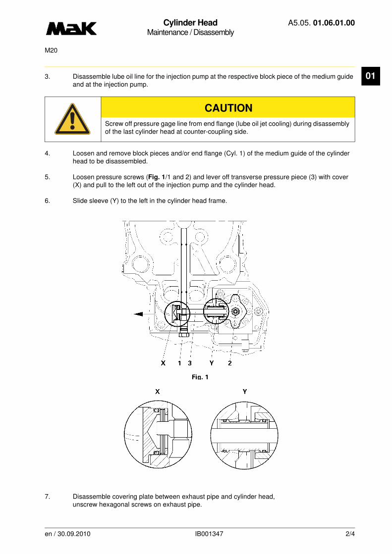
3. Disassemble lube oil line for the injection pump at the respective block piece of the medium guide and at the injection pump.4. Loosen and remove block pieces and/or end flange (Cyl. 1) of the medium guide of the cylinder head to be disassembled.
5. Loosen pressure screws (Fig. 1/1 and 2) and lever off transverse pressure piece (3) with cover (X) and pull to the left out of the injection pump and the cylinder head.
6. Slide sleeve (Y) to the left in the cylinder head frame.
7. Disassemble covering plate between exhaust pipe and cylinder head,unscrew hexagonal screws on exhaust pipe.
CAUTION
Screw off pressure gage line from end flange (lube oil jet cooling) during disassembly of the last cylinder head at counter-coupling side.
en / 30.09.2010 IB001347 2/4
Cylinder HeadMaintenance / Disassembly
A5.05. 01.06.01.00
M20
01
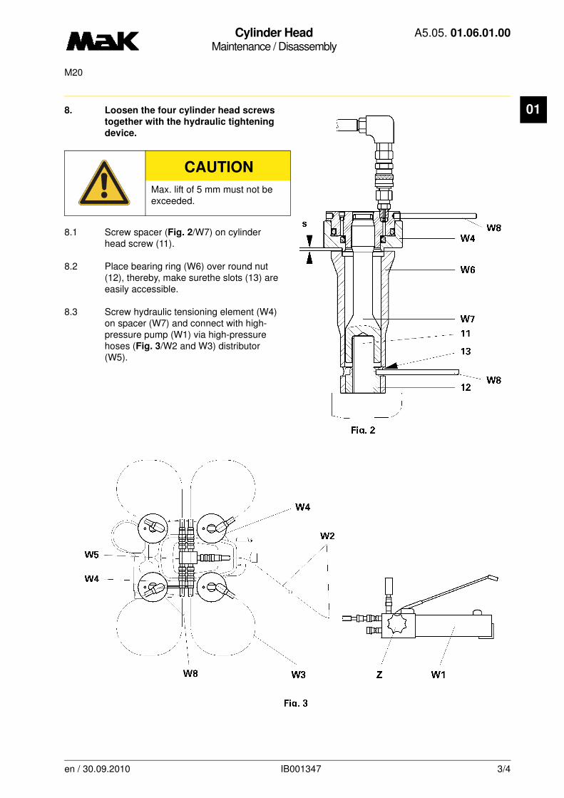
8. Loosen the four cylinder head screwstogether with the hydraulic tightening
device.
8.1 Screw spacer (Fig. 2/W7) on cylinder head screw (11).
8.2 Place bearing ring (W6) over round nut (12), thereby, make surethe slots (13) are easily accessible.
8.3 Screw hydraulic tensioning element (W4) on spacer (W7) and connect with high-pressure pump (W1) via high-pressure hoses (Fig. 3/W2 and W3) distributor (W5).
CAUTION
Max. lift of 5 mm must not be exceeded.
en / 30.09.2010 IB001347 3/4
Cylinder HeadMaintenance / Disassembly
A5.05. 01.06.01.00
M20
01
8.4 Press hydraulic tensioning element (Fig. 3/W4) with pin (W8), by turningdown against the bearing ring (W6) onto block length (Valve [Z] at the high-pressure pump [W1] is open) and establish gap of2.5 mm
(approx. 1 rotation) (Fig. 2/S).
8.5 Close valve (Fig. 3/Z) at high-pressure pump (W1) and at the same time extend all 4 cylinder head screws continuously with a hydraulic pressure of
p = 600 bar.
8.6 Disconnect round nuts (Fig. 2/12) with pin (W8).
8.7 Release tensioning elements, romove hydr. equipment and screw off round nuts.
9. Mount the cylinder head lifting gear (W11) on the cylinder head by means of the attached hexagon nut M12x35.Lift the cylinder head by means of a crane.Thereby, observe push-rod fitting!
10. Place cylinder head down on a wooden support.
NOTE
If the round nuts cannot be loosened, the cylinder head screw can be further prestressed with approx.
50 bar.
If the pressure is increased further, there is a risk of the round nut sticking due to stretching of the bolt thread.
CAUTION
Risk of damaging cooling water transition nozzles, cylinder head screws, push rods and charge air intake nozzles.
en / 30.09.2010 IB001347 4/4

Nozzle SleeveMaintenance / Disassembly and reassembly
A5.05. 01.06.50.00
15000M20
01
-------
See also: 01.06.01.nn, 07.07.01.nn
Spare parts list: B1.05.01.2.2107
Time requirement: 1 Pers./ 0,50 h
Personnel qualification: skilled engine hand
-------------------------------------------------------------------------------------------------------------------------
Operating medium: Heavy fuel and distillate fuel
Maintenance:
Change the O-rings every 15.000 h
Tools:
Pin spanner W1 2.9122 BRing spanner A/F 27 W2* 1.9456 BTorque wrench W3* 1.9454-6
* no illustration
Auxiliary material
Vaseline**High-temperature thread paste “Dag S-5080“**
**or product of equal standard
Sequence of operations:
1. Dismount the nozzle sleeve (1).
1.1 Attach the pin spanner (W1) to the nozzle sleeve (1) so that nozzle sleeve and pin spanner are engaged.
1.2 Attach the ring spanner (W2) to the pin spanner and unscrew the nozzle sleeve until nozzle sleeve and cylinder head (2) are fully unscrewed and loose.
1.3 Use a brass mandrel and gently drive out the nozzle sleeve.
CAUTION
Nozzle sleeve and cylinder head must be fully unscrewed and loose.
3
4
1
2
W1
en / 30.09.2010 IB021941 1/2
Nozzle SleeveMaintenance / Disassembly and reassembly
A5.05. 01.06.50.00
15000M20
01
1.4 Remove the O-rings (3 and 4).2. Mount the nozzle sleeve
2.1 Apply a film of green soft soap to the new black O-ring and insert it in the groove (4). Make sure the O-ring is not twisted.
2.2 Apply a film of green soft soap to the new green O-ring and insert it in the groove (3). Make sure the O-ring is not twisted.
2.3 Grease the threads of the nozzle sleeve with high-temperature thread paste.
2.4 Insert the nozzle sleeve and tighten the sleeve with the pin spanner (hand-tight).
2.5 Tighten the nozzle sleeve at a torque of
M =100 Nm.
CAUTION
Do not change the position of the O-rings. Observe the mounting instructions.
en / 30.09.2010 IB021941 2/2
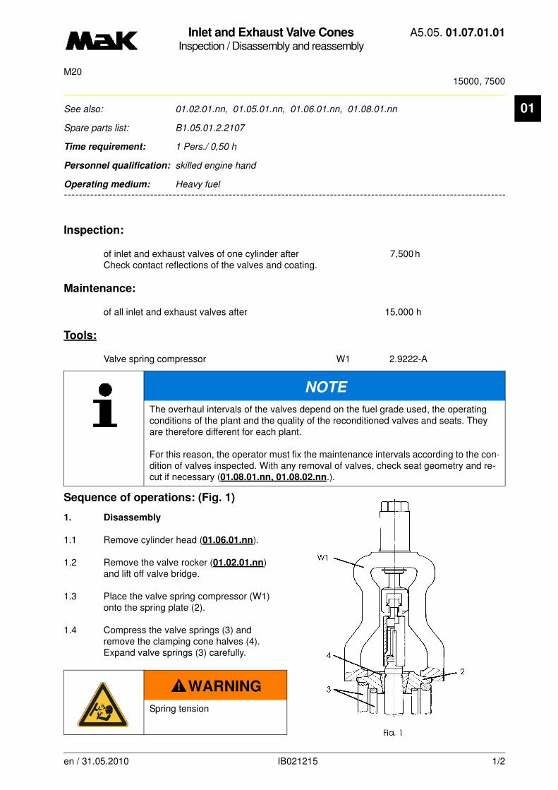
Inlet and Exhaust Valve ConesInspection / Disassembly and reassembly
A5.05. 01.07.01.01
15000, 7500M20
01
-------
See also: 01.02.01.nn, 01.05.01.nn, 01.06.01.nn, 01.08.01.nn
Spare parts list: B1.05.01.2.2107
Time requirement: 1 Pers./ 0,50 h
Personnel qualification: skilled engine hand
-------------------------------------------------------------------------------------------------------------------------
Operating medium: Heavy fuel
Inspection:
of inlet and exhaust valves of one cylinder after 7,500 h Check contact reflections of the valves and coating.
Maintenance:
of all inlet and exhaust valves after 15,000 h
Tools:
Valve spring compressor W1 2.9222-A
Sequence of operations: (Fig. 1)
1. Disassembly
1.1 Remove cylinder head (01.06.01.nn).
1.2 Remove the valve rocker (01.02.01.nn) and lift off valve bridge.
1.3 Place the valve spring compressor (W1) onto the spring plate (2).
1.4 Compress the valve springs (3) and remove the clamping cone halves (4). Expand valve springs (3) carefully.
NOTE
The overhaul intervals of the valves depend on the fuel grade used, the operating conditions of the plant and the quality of the reconditioned valves and seats. They are therefore different for each plant.
For this reason, the operator must fix the maintenance intervals according to the con-dition of valves inspected. With any removal of valves, check seat geometry and re-cut if necessary (01.08.01.nn, 01.08.02.nn.).
WARNING
Spring tension
en / 31.05.2010 IB021215 1/2

Inlet and Exhaust Valve ConesInspection / Disassembly and reassembly
A5.05. 01.07.01.01
15000, 7500M20
01
1.5 Remove valve spring compressor (Fig. 1/W1), spring plate (2), internal and external valve springs (3) as well as valve turning device from the cylinder cover.1.6 Extract valves from the cylinder head
2. Reassembly
2.1 Check valve guide clearance, renew the O-ring (01.05.01.nn).
2.2 Lubricate the valve stem well before fitting and fit the valve cone by screwing it in.
2.3 Assembly is carried out in reverse order to removal.
2.4 After inserting the clamping cone halves, slowly expand the valve springs and make sure that the clamping cone halves are in the correct position.
NOTE
Renew any valves which are heavily worn in the clamping area and any clamping cone halves which have large burrs. Remove projecting burrs before disassembling such valves. Maintenance of valve cone/valve seat (01.08.01.nn/01.08.02.nn).
en / 31.05.2010 IB021215 2/2
Valve ConesRepair / Checking
A5.05. 01.08.01.00
M20
01
-------
See also: 01.07.01.nn, 01.08.02.nn
Spare parts list: B1.05.01.2.2107
Time requirement: 0 Pers./ 0,00 h
Personnel qualification: Chief engineer / skilled engine hand
-------------------------------------------------------------------------------------------------------------------------
Operating medium: Heavy fuel and distillate fuel
Tools:
Valve refacer W1 2.9224-A
Auxiliary material:
Diamond paste Dp 30/10 - 15 µm *Thinner F25 *
* or a product of equal standard
Sequence of operations:
1. Check of valve condition
1.1 Valves may be reused without refinishing when
• the circumference of the valve cone face is metallic bright
• the valve cone face does not indicate carbon pockets with blowholes,
• by inspecting cracks, using magnifying glass with light (8 fold magnification) or powder spraying procedure (Met L'Check) and/or in the flux procedure, no crack formation is discovered at the valve cone face.
NOTE
Grind new or refinished and/or used undamaged inlet and exhaust valve cones befo-re the installation in accordance with sequence of operations 4.
Refinishing of the valve cones (in accordance with sequence of operations 3) may be necessary in the following cases:
•after extended operating periods,
•in the case of negative result, e.g. damaged sealing faces, deep scars, uneven
contact reflections of the valve cone/seat
en / 31.05.2010 IB001351 1/5

Valve ConesRepair / Checking
A5.05. 01.08.01.00
M20
01
• when the deviation from the straightness is not greater than the following values (Fig. 1).Measuring range “s” = 200 mm
= support points for test device
• when the radial run-outs of the valve cones do not exceed the following values:
1.2 Valves cannot be reused when
• the valve cone face is damaged (cracks,blowholes)
• the wear caused by corrosive material is > 2 %
of the valve head diameter (comparison with new valve)
• concave burns “s” caused by high-temperature corrosion at the lower side of the valve head
> 1.5 mm (Fig. 2)
• the lower part of the valve head indicates severe pitting (formation of so-called “paving stones”)
• corrosion pits and mechanical damage in the area of the valve stem, stem transition and valve head
• refinishing limit dimension is exceeded.
en / 31.05.2010 IB001351 2/5
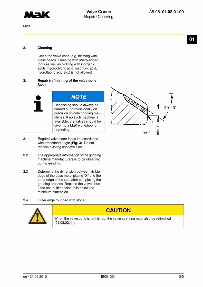
Valve ConesRepair / Checking
A5.05. 01.08.01.00
M20
01
2. Cleaning
Clean the valve cone, e.g. blasting with glass beads. Cleaning with sharp-edged tools as well as pickling with inorganic acids (hydrochloric acid, sulphuric acid, hydrofluoric acid etc.) is not allowed.
3. Repair (refinishing of the valve cone
face)
3.1 Regrind valve cone faces in accordance with prescribed angle (Fig. 3). Do not refinish existing concave fillet.
3.2 The appropriate information of the grinding machine manufacturers is to be observed during grinding.
3.3 Determine the dimension between visible edge of the base metal plating “X” and the outer edge of the seat after completing the grinding process. Replace the valve cone if the actual dimension falls below the minimum dimension.
3.4 Outer edge rounded with stone.
NOTE
Refinishing should always be carried out professionally on precision spindle grinding ma-chines. If no such machine is available, the valves should be given to a MaK workshop for regrinding.
CAUTION
When the valve cone is refinished, the valve seat ring must also be refinished (01.08.02.nn).
min
. 1
mm
en / 31.05.2010 IB001351 3/5
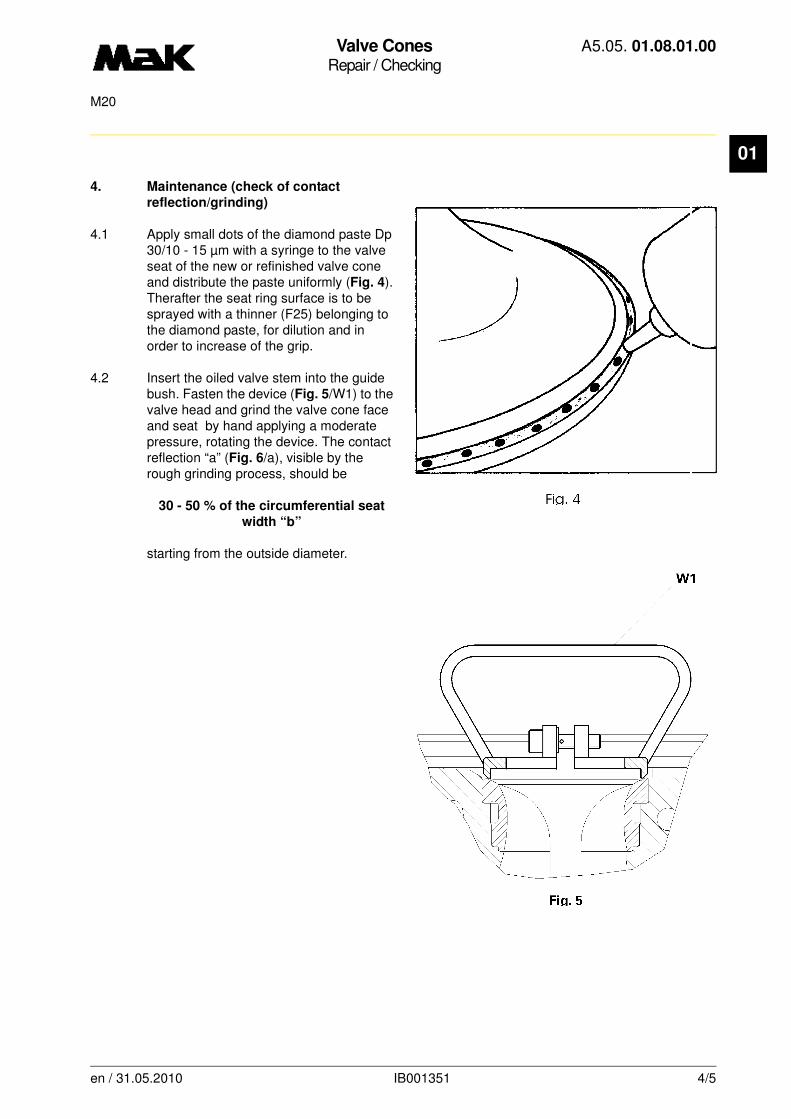
Valve ConesRepair / Checking
A5.05. 01.08.01.00
M20
01
4. Maintenance (check of contact
reflection/grinding)
4.1 Apply small dots of the diamond paste Dp 30/10 - 15 µm with a syringe to the valve seat of the new or refinished valve cone and distribute the paste uniformly (Fig. 4). Therafter the seat ring surface is to be sprayed with a thinner (F25) belonging to the diamond paste, for dilution and in order to increase of the grip.
4.2 Insert the oiled valve stem into the guide bush. Fasten the device (Fig. 5/W1) to the valve head and grind the valve cone face and seat by hand applying a moderate pressure, rotating the device. The contact reflection “a” (Fig. 6/a), visible by the rough grinding process, should be
30 - 50 % of the circumferential seat
width “b”
starting from the outside diameter.
en / 31.05.2010 IB001351 4/5
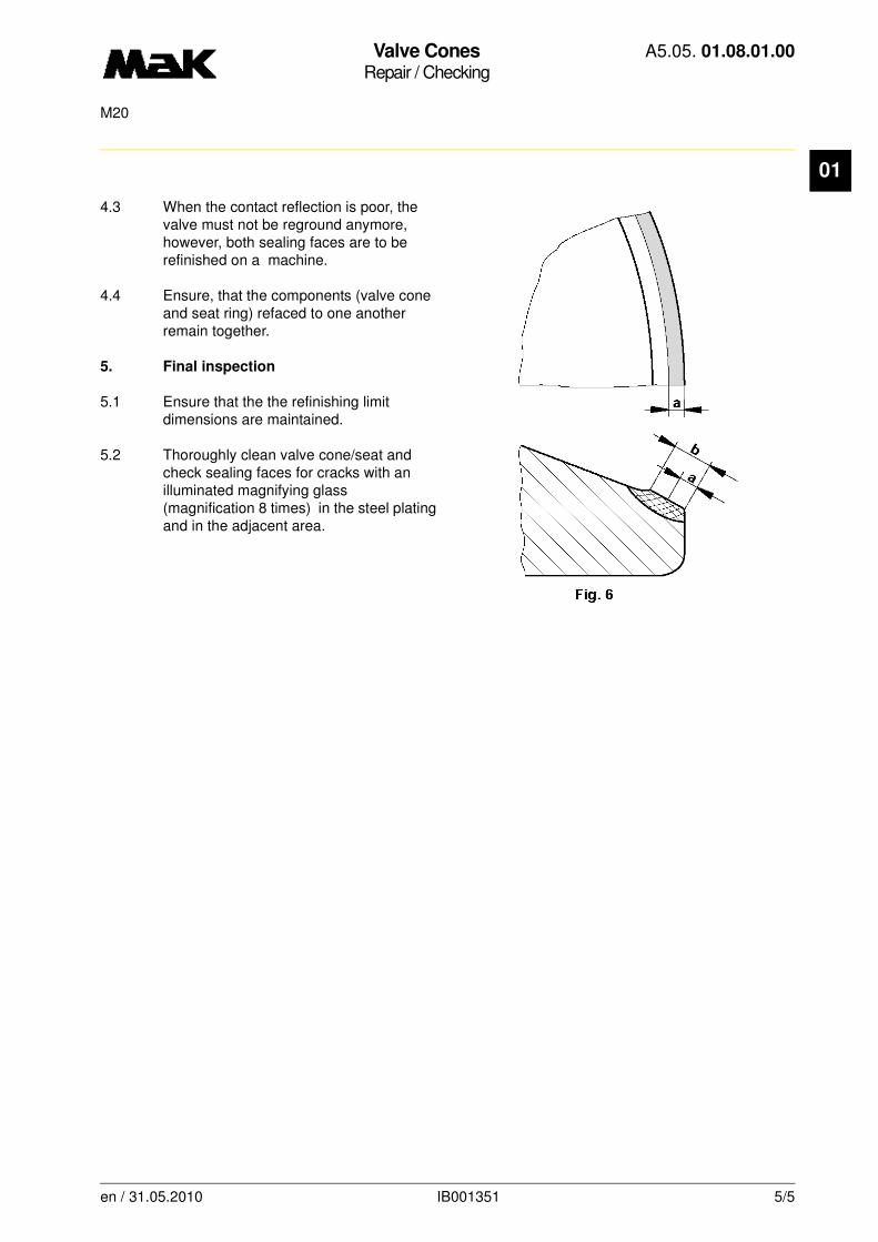
Valve ConesRepair / Checking
A5.05. 01.08.01.00
M20
01
4.3 When the contact reflection is poor, the valve must not be reground anymore, however, both sealing faces are to be refinished on a machine.
4.4 Ensure, that the components (valve cone and seat ring) refaced to one another remain together.
5. Final inspection
5.1 Ensure that the the refinishing limit dimensions are maintained.
5.2 Thoroughly clean valve cone/seat and check sealing faces for cracks with an illuminated magnifying glass (magnification 8 times) in the steel plating and in the adjacent area.
en / 31.05.2010 IB001351 5/5

Inlet Valve ConesRepair / Checking
A5.05. 01.08.01.01
M20
01
-------
See also: 01.07.01.nn, 01.08.02.nn
Spare parts list: B1.05.01.2.2107
Time requirement: 0 Pers./ 0,00 h
Personnel qualification: Chief engineer / skilled engine hand
-------------------------------------------------------------------------------------------------------------------------
Operating medium: Heavy fuel and distillate fuel
Tools:
Valve refacer W1 2.9224-A
Auxiliary material:
Diamond paste Dp 30/10 - 15 µm *Thinner F25 *
* or a product of equal standard
Sequence of operations:
1. Check of valve condition
1.1 Valves may be reused without refinishing when
• the circumference of the valve cone face is metallic bright
• the valve cone face does not indicate carbon pockets with blowholes,
• by inspecting cracks, using magnifying glass with light (8 fold magnification) or powder spraying procedure (Met L'Check) and/or in the flux procedure, no crack formation is discovered at the valve cone face.
NOTE
Grind new or refinished and/or used undamaged inlet valve cones before the installa-tion in accordance with sequence of operations 4.
Refinishing of the valve cones (in accordance with sequence of operations 3) may be necessary in the following cases:
•after extended operating periods,
•in the case of negative result, e.g. damaged sealing faces, deep scars, uneven con-tact reflections of the valve cone/seat.
en / 31.05.2010 IB022652 1/5
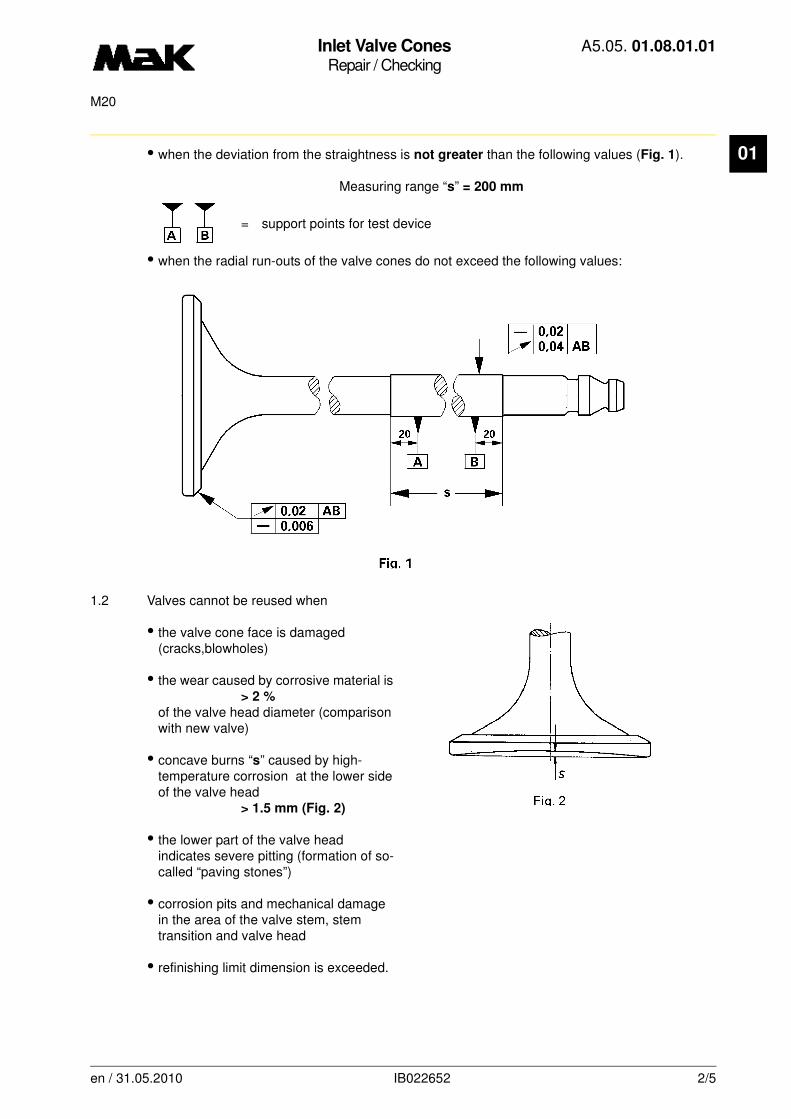
Inlet Valve ConesRepair / Checking
A5.05. 01.08.01.01
M20
01
• when the deviation from the straightness is not greater than the following values (Fig. 1).Measuring range “s” = 200 mm
= support points for test device
• when the radial run-outs of the valve cones do not exceed the following values:
1.2 Valves cannot be reused when
• the valve cone face is damaged (cracks,blowholes)
• the wear caused by corrosive material is > 2 %
of the valve head diameter (comparison with new valve)
• concave burns “s” caused by high-temperature corrosion at the lower side of the valve head
> 1.5 mm (Fig. 2)
• the lower part of the valve head indicates severe pitting (formation of so-called “paving stones”)
• corrosion pits and mechanical damage in the area of the valve stem, stem transition and valve head
• refinishing limit dimension is exceeded.
en / 31.05.2010 IB022652 2/5
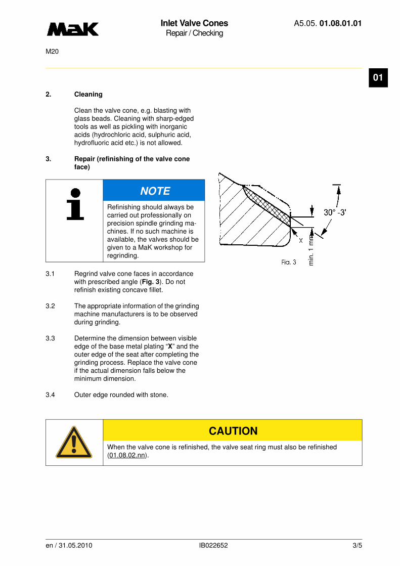
Inlet Valve ConesRepair / Checking
A5.05. 01.08.01.01
M20
01
2. Cleaning
Clean the valve cone, e.g. blasting with glass beads. Cleaning with sharp-edged tools as well as pickling with inorganic acids (hydrochloric acid, sulphuric acid, hydrofluoric acid etc.) is not allowed.
3. Repair (refinishing of the valve cone
face)
3.1 Regrind valve cone faces in accordance with prescribed angle (Fig. 3). Do not refinish existing concave fillet.
3.2 The appropriate information of the grinding machine manufacturers is to be observed during grinding.
3.3 Determine the dimension between visible edge of the base metal plating “X” and the outer edge of the seat after completing the grinding process. Replace the valve cone if the actual dimension falls below the minimum dimension.
3.4 Outer edge rounded with stone.
NOTE
Refinishing should always be carried out professionally on precision spindle grinding ma-chines. If no such machine is available, the valves should be given to a MaK workshop for regrinding.
CAUTION
When the valve cone is refinished, the valve seat ring must also be refinished (01.08.02.nn).
min
. 1
mm
en / 31.05.2010 IB022652 3/5

Inlet Valve ConesRepair / Checking
A5.05. 01.08.01.01
M20
01
4. Maintenance (check of contact
reflection/grinding)
4.1 Apply small dots of the diamond paste Dp 30/10 - 15 µm with a syringe to the valve seat of the new or refinished valve cone and distribute the paste uniformly (Fig. 4). Therafter the seat ring surface is to be sprayed with a thinner (F25) belonging to the diamond paste, for dilution and in order to increase of the grip.
4.2 Insert the oiled valve stem into the guide bush. Fasten the device (Fig. 5/W1) to the valve head and grind the valve cone face and seat by hand applying a moderate pressure, rotating the device. The contact reflection “a” (Fig. 6/a), visible by the rough grinding process, should be
30 - 50 % of the circumferential seat
width “b”
starting from the outside diameter.
en / 31.05.2010 IB022652 4/5

Inlet Valve ConesRepair / Checking
A5.05. 01.08.01.01
M20
01
4.3 When the contact reflection is poor, the valve must not be reground anymore, however, both sealing faces are to be refinished on a machine.
4.4 Ensure, that the components (valve cone and seat ring) refaced to one another remain together.
5. Final inspection
5.1 Ensure that the the refinishing limit dimensions are maintained.
5.2 Thoroughly clean valve cone/seat and check sealing faces for cracks with an illuminated magnifying glass (magnification 8 times) in the steel plating and in the adjacent area.
en / 31.05.2010 IB022652 5/5
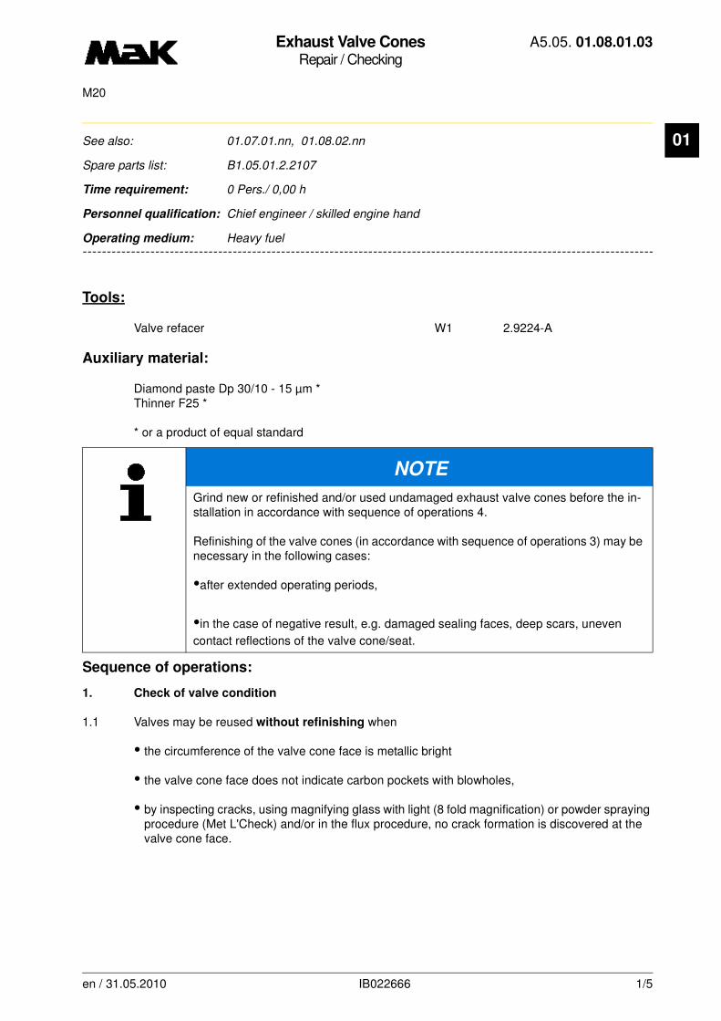
Exhaust Valve ConesRepair / Checking
A5.05. 01.08.01.03
M20
01
-------
See also: 01.07.01.nn, 01.08.02.nn
Spare parts list: B1.05.01.2.2107
Time requirement: 0 Pers./ 0,00 h
Personnel qualification: Chief engineer / skilled engine hand
-------------------------------------------------------------------------------------------------------------------------
Operating medium: Heavy fuel
Tools:
Valve refacer W1 2.9224-A
Auxiliary material:
Diamond paste Dp 30/10 - 15 µm *Thinner F25 *
* or a product of equal standard
Sequence of operations:
1. Check of valve condition
1.1 Valves may be reused without refinishing when
• the circumference of the valve cone face is metallic bright
• the valve cone face does not indicate carbon pockets with blowholes,
• by inspecting cracks, using magnifying glass with light (8 fold magnification) or powder spraying procedure (Met L'Check) and/or in the flux procedure, no crack formation is discovered at the valve cone face.
NOTE
Grind new or refinished and/or used undamaged exhaust valve cones before the in-stallation in accordance with sequence of operations 4.
Refinishing of the valve cones (in accordance with sequence of operations 3) may be necessary in the following cases:
•after extended operating periods,
•in the case of negative result, e.g. damaged sealing faces, deep scars, uneven
contact reflections of the valve cone/seat.
en / 31.05.2010 IB022666 1/5

Exhaust Valve ConesRepair / Checking
A5.05. 01.08.01.03
M20
01
• when the deviation from the straightness is not greater than the following values (Fig. 1).Measuring range “s” = 200 mm
= support points for test device
• when the radial run-outs of the valve cones do not exceed the following values:
1.2 Valves cannot be reused when
• the valve cone face is damaged (cracks,blowholes)
• the wear caused by corrosive material is > 2 %
of the valve head diameter (comparison with new valve)
• concave burns “s” caused by high-temperature corrosion at the lower side of the valve head
> 1.5 mm (Fig. 2)
• the lower part of the valve head indicates severe pitting (formation of so-called “paving stones”)
• corrosion pits and mechanical damage in the area of the valve stem, stem transition and valve head
• refinishing limit dimension is exceeded.
en / 31.05.2010 IB022666 2/5
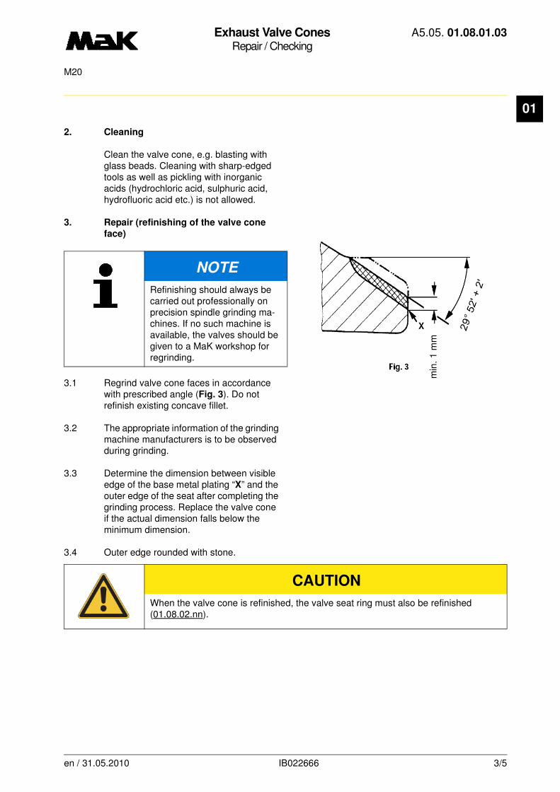
Exhaust Valve ConesRepair / Checking
A5.05. 01.08.01.03
M20
01
2. Cleaning
Clean the valve cone, e.g. blasting with glass beads. Cleaning with sharp-edged tools as well as pickling with inorganic acids (hydrochloric acid, sulphuric acid, hydrofluoric acid etc.) is not allowed.
3. Repair (refinishing of the valve cone
face)
3.1 Regrind valve cone faces in accordance with prescribed angle (Fig. 3). Do not refinish existing concave fillet.
3.2 The appropriate information of the grinding machine manufacturers is to be observed during grinding.
3.3 Determine the dimension between visible edge of the base metal plating “X” and the outer edge of the seat after completing the grinding process. Replace the valve cone if the actual dimension falls below the minimum dimension.
3.4 Outer edge rounded with stone.
NOTE
Refinishing should always be carried out professionally on precision spindle grinding ma-chines. If no such machine is available, the valves should be given to a MaK workshop for regrinding.
CAUTION
When the valve cone is refinished, the valve seat ring must also be refinished (01.08.02.nn).
min
. 1 m
m
en / 31.05.2010 IB022666 3/5
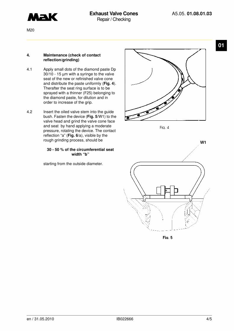
Exhaust Valve ConesRepair / Checking
A5.05. 01.08.01.03
M20
01
4. Maintenance (check of contact
reflection/grinding)
4.1 Apply small dots of the diamond paste Dp 30/10 - 15 µm with a syringe to the valve seat of the new or refinished valve cone and distribute the paste uniformly (Fig. 4). Therafter the seat ring surface is to be sprayed with a thinner (F25) belonging to the diamond paste, for dilution and in order to increase of the grip.
4.2 Insert the oiled valve stem into the guide bush. Fasten the device (Fig. 5/W1) to the valve head and grind the valve cone face and seat by hand applying a moderate pressure, rotating the device. The contact reflection “a” (Fig. 6/a), visible by the rough grinding process, should be
30 - 50 % of the circumferential seat
width “b”
starting from the outside diameter.
en / 31.05.2010 IB022666 4/5
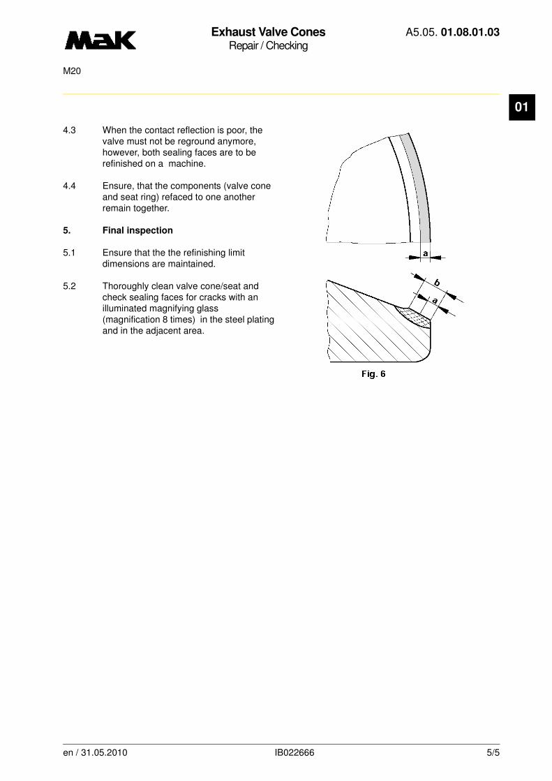
Exhaust Valve ConesRepair / Checking
A5.05. 01.08.01.03
M20
01
4.3 When the contact reflection is poor, the valve must not be reground anymore, however, both sealing faces are to be refinished on a machine.
4.4 Ensure, that the components (valve cone and seat ring) refaced to one another remain together.
5. Final inspection
5.1 Ensure that the the refinishing limit dimensions are maintained.
5.2 Thoroughly clean valve cone/seat and check sealing faces for cracks with an illuminated magnifying glass (magnification 8 times) in the steel plating and in the adjacent area.
en / 31.05.2010 IB022666 5/5
Inlet Valve ConesRepair / Checking
A5.05. 01.08.01.04
M20
01
-------
See also: 01.07.01.nn, 01.08.02.nn
Spare parts list: B1.05.01.2.2107
Time requirement: 0 Pers./ 0,00 h
Personnel qualification: Chief engineer / skilled engine hand
-------------------------------------------------------------------------------------------------------------------------
Operating medium: Heavy fuel and distillate fuel
Tools:
Valve refacer W1 2.9224-A
Auxiliary material:
Diamond paste Dp 30/10 - 15 µm *Thinner F25 *
* or a product of equal standard
Sequence of operations:
1. Check of valve condition
1.1 Valves may be reused without refinishing when
• the circumference of the valve cone face is metallic bright
• the valve cone face does not indicate carbon pockets with blowholes,
• by inspecting cracks, using magnifying glass with light (8 fold magnification) or powder spraying procedure (Met L'Check) and/or in the flux procedure, no crack formation is discovered at the valve cone face.
NOTE
Grind new or refinished and/or used undamaged inlet valve cones before the installa-tion in accordance with sequence of operations 4.
Refinishing of the valve cones (in accordance with sequence of operations 3) may be necessary in the following cases:
•after extended operating periods,
•in the case of negative result, e.g. damaged sealing faces, deep scars, uneven
contact reflections of the valve cone/seat.
en / 05.10.2010 IB023324 1/5
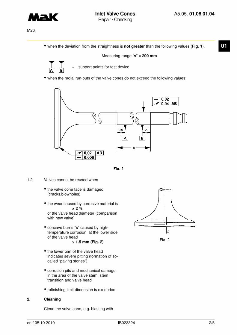
Inlet Valve ConesRepair / Checking
A5.05. 01.08.01.04
M20
01
• when the deviation from the straightness is not greater than the following values (Fig. 1).Measuring range “s” = 200 mm
= support points for test device
• when the radial run-outs of the valve cones do not exceed the following values:
1.2 Valves cannot be reused when
• the valve cone face is damaged (cracks,blowholes)
• the wear caused by corrosive material is > 2 %
of the valve head diameter (comparison with new valve)
• concave burns “s” caused by high-temperature corrosion at the lower side of the valve head
> 1.5 mm (Fig. 2)
• the lower part of the valve head indicates severe pitting (formation of so-called “paving stones”)
• corrosion pits and mechanical damage in the area of the valve stem, stem transition and valve head
• refinishing limit dimension is exceeded.
2. Cleaning
Clean the valve cone, e.g. blasting with
en / 05.10.2010 IB023324 2/5

Inlet Valve ConesRepair / Checking
A5.05. 01.08.01.04
M20
01
glass beads. Cleaning with sharp-edged tools as well as pickling with inorganic acids (hydrochloric acid, sulphuric acid, hydrofluoric acid etc.) is not allowed.3. Repair (refinishing of the valve cone
face)
3.1 Regrind valve cone faces in accordance with prescribed angle (Fig. 3). Do not refinish existing concave fillet.
3.2 The appropriate information of the grinding machine manufacturers is to be observed during grinding.
3.3 Determine the dimension between visible edge of the base metal plating “X” and the outer edge of the seat after completing the grinding process. Replace the valve cone if the actual dimension falls below the minimum dimension.
3.4 Outer edge rounded with stone.
NOTE
Refinishing should always be carried out professionally on precision spindle grinding machines. If no such machine is available, the valves should be given to a MaK workshop for regrinding.
CAUTION
When the valve cone is refinished, the valve seat ring must also be refinished (01.08.02.nn).
min
. 1 m
m
en / 05.10.2010 IB023324 3/5

Inlet Valve ConesRepair / Checking
A5.05. 01.08.01.04
M20
01
4. Maintenance (check of contact
reflection/grinding)
4.1 Apply small dots of the diamond paste Dp 30/10 - 15 µm with a syringe to the valve seat of the new or refinished valve cone and distribute the paste uniformly (Fig. 4). Therafter the seat ring surface is to be sprayed with a thinner (F25) belonging to the diamond paste, for dilution and in order to increase of the grip.
4.2 Insert the oiled valve stem into the guide bush. Fasten the device (Fig. 5/W1) to the valve head and grind the valve cone face and seat by hand applying a moderate pressure, rotating the device. The contact reflection “a” (Fig. 6/a), visible by the rough grinding process, should be
30 - 50 % of the circumferential seat
width “b”
starting from the outside diameter.
en / 05.10.2010 IB023324 4/5
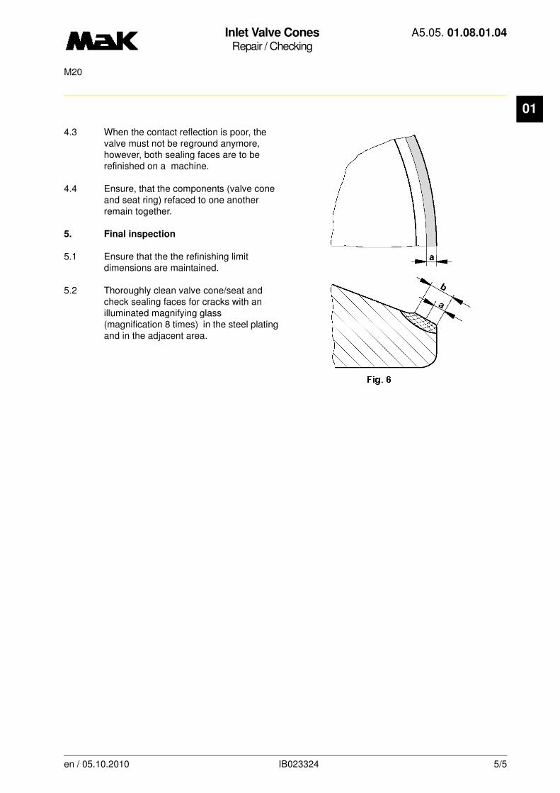
Inlet Valve ConesRepair / Checking
A5.05. 01.08.01.04
M20
01
4.3 When the contact reflection is poor, the valve must not be reground anymore, however, both sealing faces are to be refinished on a machine.
4.4 Ensure, that the components (valve cone and seat ring) refaced to one another remain together.
5. Final inspection
5.1 Ensure that the the refinishing limit dimensions are maintained.
5.2 Thoroughly clean valve cone/seat and check sealing faces for cracks with an illuminated magnifying glass (magnification 8 times) in the steel plating and in the adjacent area.
en / 05.10.2010 IB023324 5/5
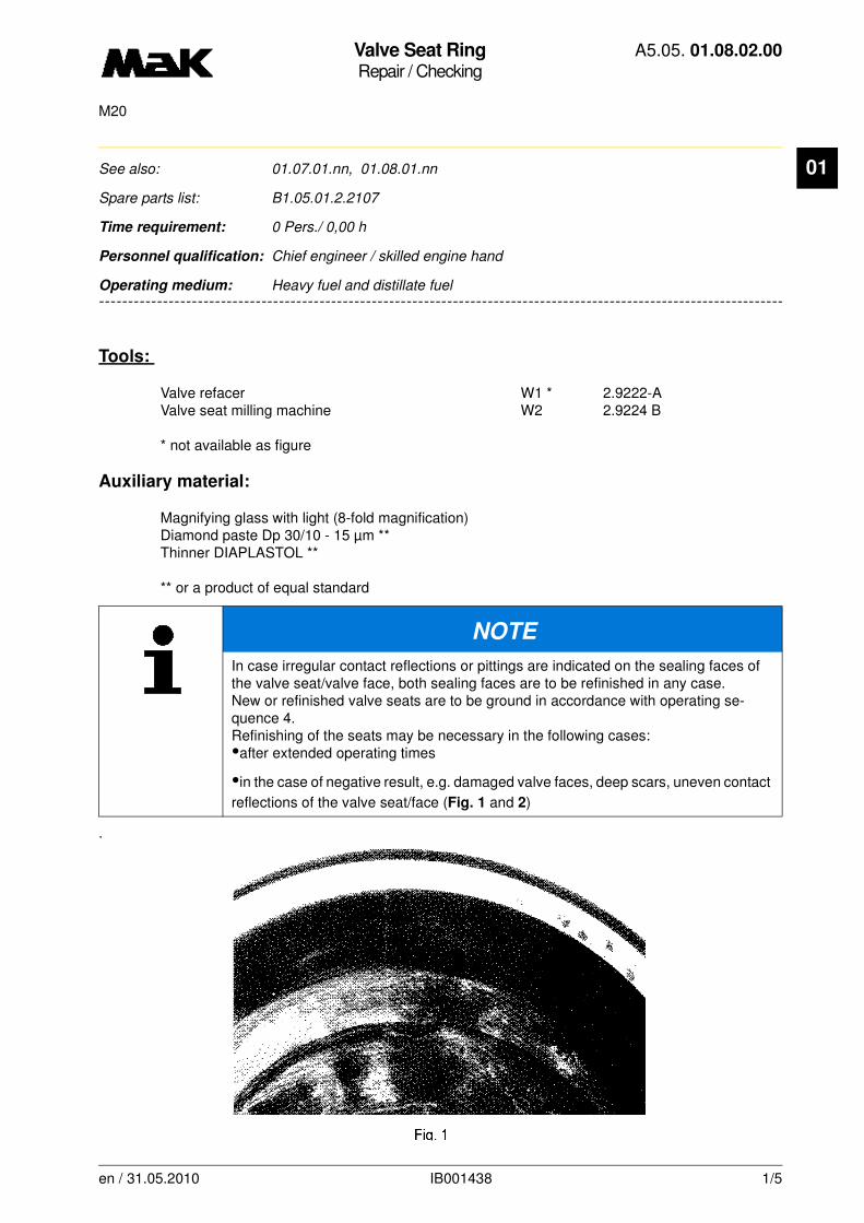
Valve Seat RingRepair / Checking
A5.05. 01.08.02.00
M20
01
-------
See also: 01.07.01.nn, 01.08.01.nn
Spare parts list: B1.05.01.2.2107
Time requirement: 0 Pers./ 0,00 h
Personnel qualification: Chief engineer / skilled engine hand
-------------------------------------------------------------------------------------------------------------------------
Operating medium: Heavy fuel and distillate fuel
Tools:
Valve refacer W1 * 2.9222-AValve seat milling machine W2 2.9224 B
* not available as figure
Auxiliary material:
Magnifying glass with light (8-fold magnification)Diamond paste Dp 30/10 - 15 µm ** Thinner DIAPLASTOL **
** or a product of equal standard
.
NOTE
In case irregular contact reflections or pittings are indicated on the sealing faces of the valve seat/valve face, both sealing faces are to be refinished in any case.New or refinished valve seats are to be ground in accordance with operating se-quence 4.Refinishing of the seats may be necessary in the following cases:•after extended operating times
•in the case of negative result, e.g. damaged valve faces, deep scars, uneven contact
reflections of the valve seat/face (Fig. 1 and 2)
en / 31.05.2010 IB001438 1/5
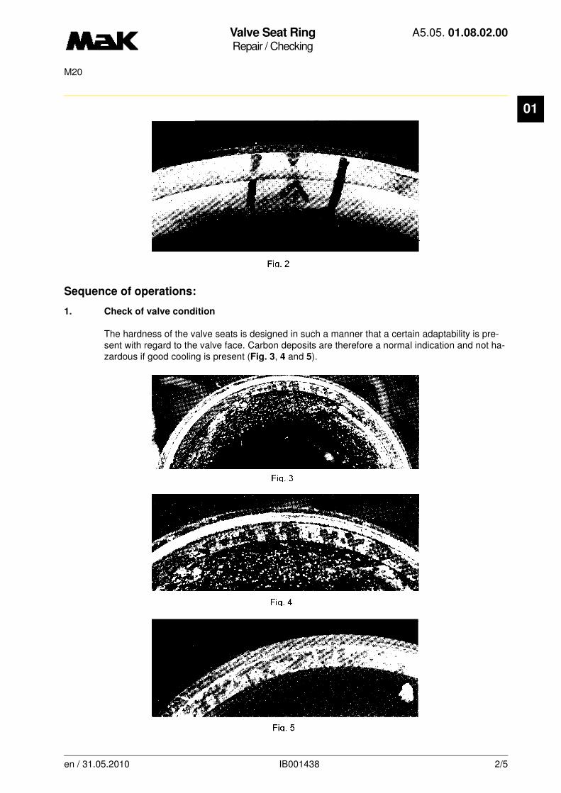
Valve Seat RingRepair / Checking
A5.05. 01.08.02.00
M20
01
Sequence of operations:
1. Check of valve condition
The hardness of the valve seats is designed in such a manner that a certain adaptability is pre-sent with regard to the valve face. Carbon deposits are therefore a normal indication and not ha-zardous if good cooling is present (Fig. 3, 4 and 5).
en / 31.05.2010 IB001438 2/5

Valve Seat RingRepair / Checking
A5.05. 01.08.02.00
M20
01
1.1 The valve seat rings are reusable without refinishing when• the circumference of valve face is metallic bright
• no carbon deposits with blow holes or visible wear are present
• by inspecting cracks using an illuminated magnifying glass (8-fold magnification) or powder spraying procedure (Met L'Check) and/or in the flux procedure no crack formation is established at the valve face.
1.2 The valve seat rings are not reusable when
• cracks are present in the seat face
• burn holes are present
• the refinishing limits have been exceeded.
2. Cleaning
Remove the residues from the seat faces.
3. Maintenance (refinishing the valve seat rings)
3.1 Remilling of the valve seat
3.1.1 Clean the valve seat ring thoroughly in the contact area (3) of the centering washer (4) in order to ensure an absolutely centrical fixing of the guide mandrel (5). Remove O-ring from guide bush.
3.1.2 Insert centering washer (4) with guide mandrel (5) and tighten with tension nut (6).
NOTE
Refinishing is to be carried out with the MaK precision seat grinding machine (W1) in a workmanlike manner. Refer to special operating instructions.
Alternatively the seats may be refinished by means of the MaK valve seat milling
device (Fig. 6/W2). Unnecessary stock removal is to be avoided, only carbon pockets are to be repaired if they are present in the contact area.
CAUTION
Handle the cutter head (2) with care, cutters are sensitive to impact, hard touch-down can also damage the valve seat face.
en / 31.05.2010 IB001438 3/5

Valve Seat RingRepair / Checking
A5.05. 01.08.02.00
M20
01
3.1.3 Place cutter head (Fig. 6/2) on greased mandrel, screw in knurled thumb screw (1), until resistance becomes noticeable.3.1.4 Rotate valve seat (clockwise) uniformly and slowly and remill the seat in one operation pass. The cutting of the cutters must be noticeable. Set the contact pressure by touch.
3.1.5 Prior to finishing the cutting process, slowly unscrew the knurled thumb screw (1) and simultaneously rotate the cutter head.
3.1.6 Max. permissible dimension for reworking:
Exhaust valve (Fig. 7):
The shoulder "y" must still remain di-stinct.
Inlet valve (Fig. 7a):
The dimension for "z" must not drop be-low the minimum dimension of 1 mm due to the reworking.
3.1.7 If the milling cutters are blunt, the cutter head is to be sent to MaK for refinishing.
CAUTION
The machine will rattle when the contact pressure is too low and/or the cutting speed is too high.
en / 31.05.2010 IB001438 4/5

Valve Seat RingRepair / Checking
A5.05. 01.08.02.00
M20
01
3.1.8 Dismount the milling device. Grind sharp edges with the fine emery cloth.4. Check of contact reflection/grinding
4.1 Apply small dots of the diamond paste Dp 30/10 - 15 µm with a syringe to the valve seat of the new or refinished vlave spindle and distribute the paste uniformly. Thereafter spray the complete seat ring surface with thinner DIAPLASTOL (01.08.01.nn).
4.2 Insert the lubricated valve stem into the guide bush. Fasten the device (W1) (01.08.01.nn) to the valve head and grind the valve face and seat by hand applying a moderate pressure, rotating the device. The contact reflection “a” which is visible by the rough grinding process shall be
30 - 50 % of the circumferential seat width “b”
starting from the outside diameter (01.08.01.nn).
4.3 If the contact reflection is poor, the valve must not be reground anymore, however, both sealing faces are to be refinished.
4.4 Ensure that the components (valve face and seat ring) refaced to one another will be held together.
5. Final check of valve condition
5.1 Check whether the refinishing limit dimensions have been observed.
5.2 Clean valve face/seat thoroughly and check the sealing faces with an illuminated magnifying glass (8-fold magnification) for cracks in the armouring and in the adjacent zone.
en / 31.05.2010 IB001438 5/5

Valve Seat RingRepair / Checking
A5.05. 01.08.02.01
M20
01
-------
See also: 01.07.01.nn, 01.08.01.nn
Spare parts list: B1.05.01.2.2107
Time requirement: 0 Pers./ 0,00 h
Personnel qualification: Chief engineer / skilled engine hand
-------------------------------------------------------------------------------------------------------------------------
Operating medium: Heavy fuel and distillate fuel
Tools:
Valve refacer W1 * 2.9224 AValve seat milling machine W2 2.9224 C
* not available as figure
Auxiliary material:
Magnifying glass with light (8-fold magnification)Diamond paste Dp 30/10 - 15 µm ** Thinner DIAPLASTOL **
** or a product of equal standard
NOTE
In case irregular contact reflections or pittings are indicated on the sealing faces of the valve seat/valve face, both sealing faces are to be refinished in any case.New or refinished valve seats are to be ground in accordance with operating se-quence 4.Refinishing of the seats may be necessary in the following cases:•after extended operating times
•in the case of negative result, e.g. damaged valve faces, deep scars, uneven contact
reflections of the valve seat/face (Fig. 1 and 2)
en / 30.09.2010 IB023062 1/5

Valve Seat RingRepair / Checking
A5.05. 01.08.02.01
M20
01
Sequence of operations:
1. Check of valve condition
The hardness of the valve seats is designed in such a manner that a certain adaptability is pre-sent with regard to the valve face. Carbon deposits are therefore a normal indication and not ha-zardous if good cooling is present (Fig. 3, 4 and 5).
en / 30.09.2010 IB023062 2/5

Valve Seat RingRepair / Checking
A5.05. 01.08.02.01
M20
01
1.1 The valve seat rings are reusable without refinishing when
• the circumference of valve face is metallic bright
• no carbon deposits with blow holes or visible wear are present
• by inspecting cracks using an illuminated magnifying glass (8-fold magnification) or powder spraying procedure (Met L'Check) and/or in the flux procedure no crack formation is established at the valve face.
1.2 The valve seat rings are not reusable when
• cracks are present in the seat face
• burn holes are present
• the refinishing limits have been exceeded.
2. Cleaning
Remove the residues from the seat faces.
3. Maintenance (refinishing the valve seat rings)
3.1 Remilling of the valve seat
3.1.1 Clean the valve seat ring thoroughly in the contact area (3) of the centering washer (4) in order to ensure an absolutely centrical fixing of the guide mandrel (5). Remove O-ring from guide bush.
3.1.2 Insert centering washer (4) with guide mandrel (5) and tighten with tension nut (6).
NOTE
Refinishing is to be carried out with the MaK precision seat grinding machine (W1) in a workmanlike manner. Refer to special operating instructions.
Alternatively the seats may be refinished by means of the MaK valve seat milling
device (Fig. 6/W2). Unnecessary stock removal is to be avoided, only carbon pockets are to be repaired if they are present in the contact area.
CAUTION
Handle the cutter head (2) with care, cutters are sensitive to impact, hard touch-down can also damage the valve seat face.
en / 30.09.2010 IB023062 3/5
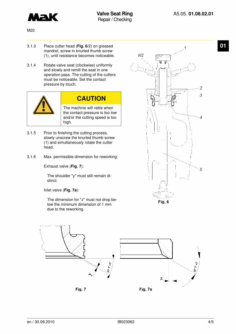
Valve Seat RingRepair / Checking
A5.05. 01.08.02.01
M20
01
3.1.3 Place cutter head (Fig. 6/2) on greased mandrel, screw in knurled thumb screw (1), until resistance becomes noticeable.3.1.4 Rotate valve seat (clockwise) uniformly and slowly and remill the seat in one operation pass. The cutting of the cutters must be noticeable. Set the contact pressure by touch.
3.1.5 Prior to finishing the cutting process, slowly unscrew the knurled thumb screw (1) and simultaneously rotate the cutter head.
3.1.6 Max. permissible dimension for reworking:
Exhaust valve (Fig. 7):
The shoulder "y" must still remain di-stinct.
Inlet valve (Fig. 7a):
The dimension for "z" must not drop be-low the minimum dimension of 1 mm due to the reworking.
CAUTION
The machine will rattle when the contact pressure is too low and/or the cutting speed is too high.
en / 30.09.2010 IB023062 4/5

Valve Seat RingRepair / Checking
A5.05. 01.08.02.01
M20
01
3.1.7 If the milling cutters are blunt, the cutter head is to be sent to MaK for refinishing.3.1.8 Dismount the milling device. Grind sharp edges with the fine emery cloth.
4. Check of contact reflection/grinding
4.1 Apply small dots of the diamond paste Dp 30/10 - 15 µm with a syringe to the valve seat of the new or refinished vlave spindle and distribute the paste uniformly. Thereafter spray the complete seat ring surface with thinner DIAPLASTOL (01.08.01.nn).
4.2 Insert the lubricated valve stem into the guide bush. Fasten the device (W1) (01.08.01.nn) to the valve head and grind the valve face and seat by hand applying a moderate pressure, rotating the device. The contact reflection “a” which is visible by the rough grinding process shall be
30 - 50 % of the circumferential seat width “b”
starting from the outside diameter (01.08.01.nn).
4.3 If the contact reflection is poor, the valve must not be reground anymore, however, both sealing faces are to be refinished.
4.4 Ensure that the components (valve face and seat ring) refaced to one another will be held together.
5. Final check of valve condition
5.1 Check whether the refinishing limit dimensions have been observed.
5.2 Clean valve face/seat thoroughly and check the sealing faces with an illuminated magnifying glass (8-fold magnification) for cracks in the armouring and in the adjacent zone.
en / 30.09.2010 IB023062 5/5
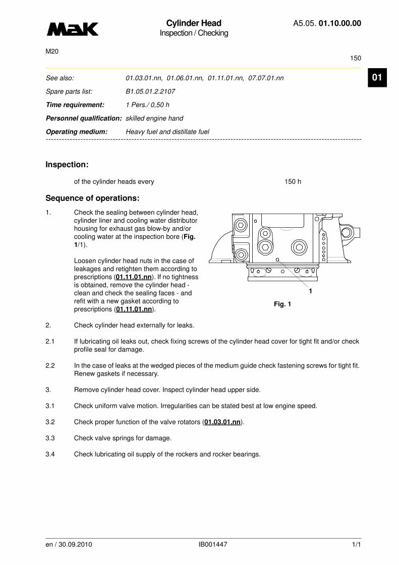
Cylinder HeadInspection / Checking
A5.05. 01.10.00.00
150M20
en / 30.09.2010 IB001447 1/1
01See also: 01.03.01.nn, 01.06.01.nn, 01.11.01.nn, 07.07.01.nn
Spare parts list: B1.05.01.2.2107
Time requirement: 1 Pers./ 0,50 h
Personnel qualification: skilled engine hand
--------------------------------------------------------------------------------------------------------------------------------
Operating medium: Heavy fuel and distillate fuel
Inspection:
of the cylinder heads every 150 h
Sequence of operations:
1. Check the sealing between cylinder head, cylinder liner and cooling water distributor housing for exhaust gas blow-by and/or cooling water at the inspection bore (Fig.
1/1).
Loosen cylinder head nuts in the case of leakages and retighten them according to prescriptions (01.11.01.nn). If no tightness is obtained, remove the cylinder head - clean and check the sealing faces - and refit with a new gasket according to prescriptions (01.11.01.nn).
2. Check cylinder head externally for leaks.
2.1 If lubricating oil leaks out, check fixing screws of the cylinder head cover for tight fit and/or check profile seal for damage.
2.2 In the case of leaks at the wedged pieces of the medium guide check fastening screws for tight fit. Renew gaskets if necessary.
3. Remove cylinder head cover. Inspect cylinder head upper side.
3.1 Check uniform valve motion. Irregularities can be stated best at low engine speed.
3.2 Check proper function of the valve rotators (01.03.01.nn).
3.3 Check valve springs for damage.
3.4 Check lubricating oil supply of the rockers and rocker bearings.
Fig. 1
1

Cylinder HeadMaintenance / Cleaning
A5.05. 01.10.01.01
15000M20
en / 31.05.2010 IB022277 1/1
01 See also: 01.02.01.nn, 01.06.01.nn, 01.07.01.nn, 07.07.01.nn
Spare parts list: B1.05.01.2.2107
Time requirement: 1 Pers./ 1,00 h
Personnel qualification: skilled engine hand
--------------------------------------------------------------------------------------------------------------------------------
Operating medium: Heavy fuel
Sequence of operations:
The following parts are disassembled:
inlet-, exhaust-, injection valve, valve rocker brackets.
1. Wash cylinder head with cold cleaner.
2. Remove carbon deposits from inlet- and exhaust ducts and cylinder head bottom (do not clean
the valve seats!) with a wire brush and scraper. Do not damage sealing recess.
3. Clean cooling water inlet and cooling water outlet.
4. Inspect cylinder head bottom for cracks especially at the valve channels.
5. Clean sealing face for injection valve.
6. Check inlet- and outlet bores of the medium guide for free access.
7. Check alarm probe for leaking fuel for function in distributor plate at connector of the medium guide (Cyl. 1).
NOTE
Put the cylinder head down with its bottom part only on a wooden support
Cylinder HeadRepair / Reassembly
A5.05. 01.11.01.00
M20
01
-------
See also: 01.01.01.nn, 01.02.01.nn, 01.06.01.nn, 02.06.01.nn, 07.07.01.nn
Spare parts list: B1.05.01.2.2107
Time requirement: 1 Pers./ 1,00 h
Personnel qualification: skilled engine hand
-------------------------------------------------------------------------------------------------------------------------
Operating medium: Heavy fuel and distillate fuel
Tools:
See maintenance sheet 01.06.01.nn.
Auxiliary material:
High-temperature thread paste “Dag S-5080” *Molykote paste “G-Rapid Plus” *Vaseline *
* or a product of equal standard
NOTE
When lifting the cylinder head or when turning afterwards, the cylinder liner is always to be secured with the hold-down to prevent the liner from coming loose.
CAUTION
Do not fall below minimum bending radius r = 120 mm of the high-pressure hoses.Only use hydraulic oil as an operating material.
DANGER
No parts of the body should be over the equipment which is under pressure.
en / 30.09.2010 IB001353 1/5
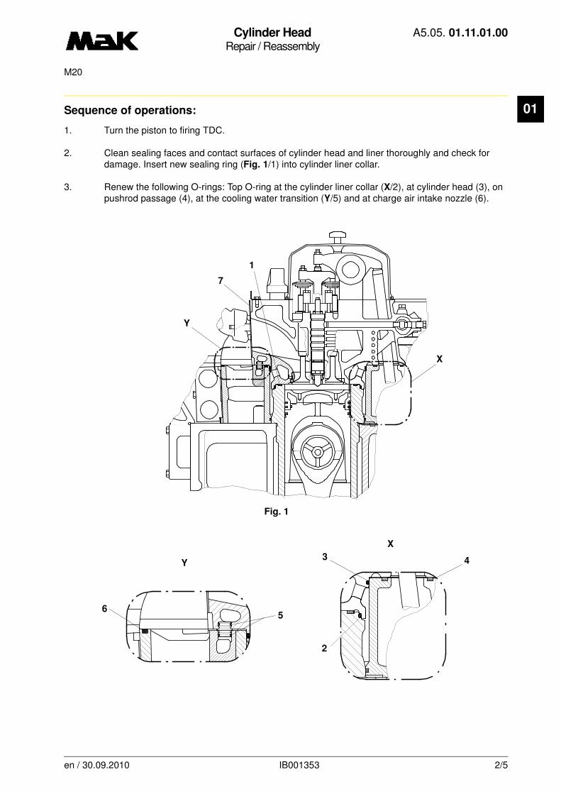
Cylinder HeadRepair / Reassembly
A5.05. 01.11.01.00
M20
01
Sequence of operations:1. Turn the piston to firing TDC.
2. Clean sealing faces and contact surfaces of cylinder head and liner thoroughly and check for damage. Insert new sealing ring (Fig. 1/1) into cylinder liner collar.
3. Renew the following O-rings: Top O-ring at the cylinder liner collar (X/2), at cylinder head (3), on pushrod passage (4), at the cooling water transition (Y/5) and at charge air intake nozzle (6).
Fig. 1
X
Y
X
1
7
Y
43
2
56
en / 30.09.2010 IB001353 2/5
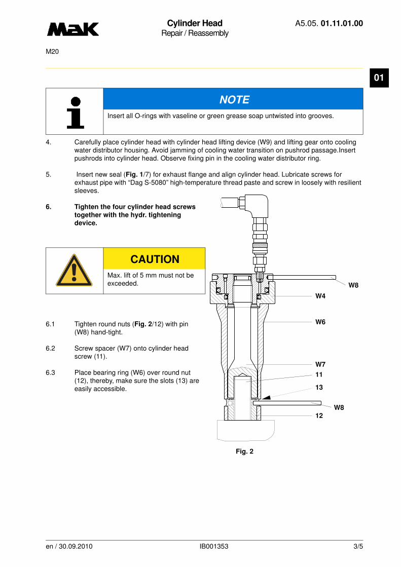
Cylinder HeadRepair / Reassembly
A5.05. 01.11.01.00
M20
01
4. Carefully place cylinder head with cylinder head lifting device (W9) and lifting gear onto cooling water distributor housing. Avoid jamming of cooling water transition on pushrod passage.Insert pushrods into cylinder head. Observe fixing pin in the cooling water distributor ring.
5. Insert new seal (Fig. 1/7) for exhaust flange and align cylinder head. Lubricate screws for exhaust pipe with “Dag S-5080” high-temperature thread paste and screw in loosely with resilient sleeves.
6. Tighten the four cylinder head screws
together with the hydr. tightening
device.
6.1 Tighten round nuts (Fig. 2/12) with pin (W8) hand-tight.
6.2 Screw spacer (W7) onto cylinder head screw (11).
6.3 Place bearing ring (W6) over round nut (12), thereby, make sure the slots (13) are easily accessible.
NOTE
Insert all O-rings with vaseline or green grease soap untwisted into grooves.
CAUTION
Max. lift of 5 mm must not be exceeded. W8
W4
W6
W7
11
13
W812
Fig. 2
en / 30.09.2010 IB001353 3/5

Cylinder HeadRepair / Reassembly
A5.05. 01.11.01.00
M20
01
6.4 Screw hydr. tensioning element (Fig. 2/W4) onto spacer (W7) and link with high-pressure pump (W1) via high-pressure hoses (Fig. 3/W2 and W3) distributor (W5).6.5 Press hydraulic tensioning element (Fig. 2/W4) by means of pin (W8) by turning down against the bearing ring (W6) onto block length and tighten hand-tight (valve [Fig. 3/Z] open at the high-pres-sure pump (W1)).
6.6 Close valve (Fig. 3/Z) at high-pressure pump (W1) and simultaneously extend all 4 cylinder head screws steadily with a hydraulic pressure of
p = 600 bar.
6.7 Firmly tighten all round nuts (Fig. 2/12) uniformly with pin (W8), ensure smooth running.
6.8 Check the fixed rest of round nuts.
• Lower pressure by 50 bar.• Round nuts should no longer be able to be loosened with the pin.
6.9 Release and remove hydraulic tensioning element.
CAUTION
Pressure must remain constant in case the pump is not activated, otherwise a tighte-ning error occurs.
W2
W3W8
W5
Z W1
Fig. 3
en / 30.09.2010 IB001353 4/5
Cylinder HeadRepair / Reassembly
A5.05. 01.11.01.00
M20
01
7. Tighten screws for exhaust pipe on alternate sides in 2 stages with a torque of
M = 60 and 110 Nm.
8. Fit disassembled block pieces and/or flanges of the medium guide with new seals. Ensure correct fit of the dowel pin.
9. Connect lube oil line and transverse thrust pieces of the respective injection pump in reverse order to the disassembly instructions (01.06.01.nn). The mounting instructions of 07.07.01.nn,
sequence of operations 2., must be observed by all means. Tighten compression screws with a torque of
M = 85 Nm.
10. Mount removed pressure gage lines and refill cooling water.
11. Set valve clearance (01.01.01.nn.) and fit pump room lining.
12. After commissioning of the engine, check tightness of all connections.
en / 30.09.2010 IB001353 5/5
Running Gear/Engine TimingInspection / Checking
A5.05. 02.01.01.00
1500, 3750M20
en / 30.09.2010 IB021322 1/1
02See also: 03.01.01.nn, 04.08.01.nn, 01.01.01.nn
Spare parts list: B1.05.03.2.1112
Time requirement: 1 Pers./ 0,50 h
Personnel qualification: Chief engineer / skilled engine hand
--------------------------------------------------------------------------------------------------------------------------------
Operating medium: Heavy fuel and distillate fuel
Sequence of operations:
1. Open indicator valve and engage turning gear.
2. Open crank case cover approx. 10 min. after shutting down the engine.
3. Check crankshaft bearings and big end bearings for even and normal temperatures.
4. Visually check screws and nuts.
5. Check extent of soiling of the engine room (silt deposits, corrosion, bearing metal particles, de-tached paint).
6. Check cylinder liner surface on engine side. Carry out lubrication oil flow check and check oil de-livery at bearing points.
7. Remove camshaft cover. Check screws of camshaft components and the lower valve mechanism for proper tightness.
8. Turn engine and check bearing surfaces of cams and rollers for scoring, pitting or other damage.
9. Check lubricating oil flow for camshaft bearing and valve mechanism.
10. Check wheel mechanism (04.08.01.nn).
11. Check oil tray and crank case for left-behind tools, cloths etc. Check seals of all crank case and sealing lids and refit cover.
12. Remove cylinder head cover. Check mechanical components like valve springs, valve bridges with guides, and rocker arms for irregularities. Look out for water or oil leaks.
NOTE
The temperature check for the bearings must be carried out with the engine at opera-ting temperature after switching off the circulation system lubrication. The remaining tasks are to be carried out after allowing a period of ventilation.

Crank Web DeflectionInspection / Measuring
A5.05. 02.02.01.00
M20
02
-------
See also:
Spare parts list: B1.05.02.2.2510, B1.05.03.2.1110
Time requirement: 2 Pers./ 1,00 h
Personnel qualification: Chief engineer / skilled engine hand
-------------------------------------------------------------------------------------------------------------------------
Operating medium: Heavy fuel and distillate fuel
Inspection:In the following cases additional measurements have to be made: In the case of suspect or dan-ger of foundation deformation, e. g.: • by collision of a ship• subsidence of the foundation• bearing or crankshaft damages• prior and after every docking of a ship.
Tools:Crank web measuring device W1 1.9425-300
a) Initial positionb) Negative deflectionc) Positive deflection
NOTE
Crank web deflection is the change in distance beween a web pair during one rotati-on of the crankshaft (Fig. 1). Depending on the location of the engine, the rigidness of the foundation and the ship, different values are given in comparison with loaded and unloaded condition of the ship as well as warm or cold engine. Measurements should therefore be carried out when the engine is warm, with normal loading and even keel; not in dock! Changes that suddenly appear or appear after a longer period under otherwise uniform conditions point to a deformation or subsiding of the founda-tion.It is therefore suggested to collect the measurement sheets extra so that the chronological allocation of the values and changes are visible. In the event of unper-missible changes, the installation must be realigned and the respective main bea-rings inspected.
en / 14.10.2010 IB001439 1/4
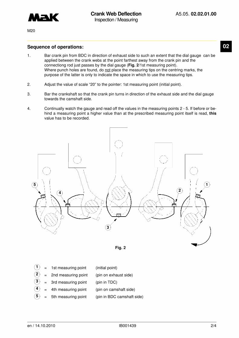
Crank Web DeflectionInspection / Measuring
A5.05. 02.02.01.00
M20
02
Sequence of operations:1. Bar crank pin from BDC in direction of exhaust side to such an extent that the dial gauge can be applied between the crank webs at the point farthest away from the crank pin and the connectiong rod just passes by the dial gauge (Fig. 2/1st measuring point).Where punch holes are found, do not place the measuring tips on the centring marks, the purpose of the latter is only to indicate the space in which to use the measuring tips.
2. Adjust the value of scale “20” to the pointer: 1st measuring point (initial point).
3. Bar the crankshaft so that the crank pin turns in direction of the exhaust side and the dial gauge towards the camshaft side.
4. Continually watch the gauge and read off the values in the measuring points 2 - 5. If before or be-hind a measuring point a higher value than at the prescribed measuring point itself is read, this
value has to be recorded.
= 1st measuring point (initial point)
= 2nd measuring point (pin on exhaust side)
= 3rd measuring point (pin in TDC)
= 4th measuring point (pin on camshaft side)
= 5th measuring point (pin in BDC camshaft side)
Fig. 2
5
3
42
1
1
2
3
4
5
en / 14.10.2010 IB001439 2/4

Crank Web DeflectionInspection / Measuring
A5.05. 02.02.01.00
M20
02
Values for crank web deflection in mm:
NOTE
Crank web deflection first of all is a criterion of the alignment of the engine with the shafting.
Heavy crank web deflection imposes additional loads on crankshaft and main bearings. This means that the admissible deflection is determined by the engine load. A high load admits less deflection than a low one.
The values below must be observed, if it is impossible to obtain the admissible limits for the plant from MaK.
Only the values measured on an engine at operating temperature has to be used for assessment. Values from a cold engine are of inferior importance.
M20
Cylinder 1 or last cylinder
with additional load + 0,04 / - 0,09 mm
(flywheel/coupling)
All cylinders
without external load + 0,04 / - 0,06 mm
Permissible values for realignment
of base frame mounted gensets + 0,03 / - 0,03 mm
in horizontal direction
en / 14.10.2010 IB001439 3/4
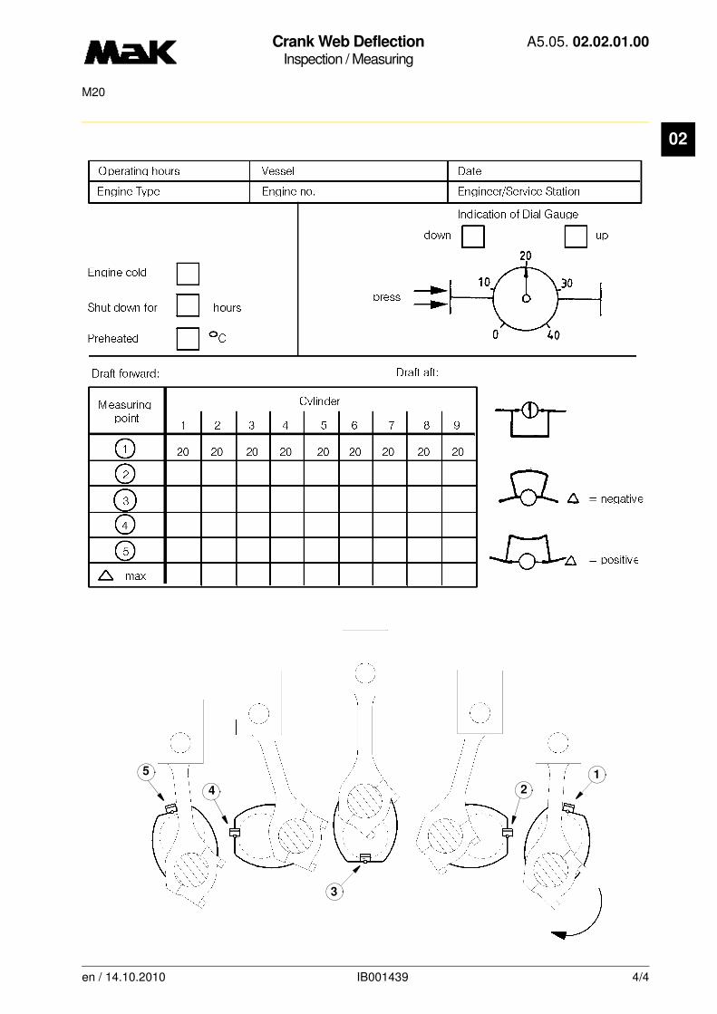
Crank Web DeflectionInspection / Measuring
A5.05. 02.02.01.00
M20
02
5
3
4 2
1
en / 14.10.2010 IB001439 4/4
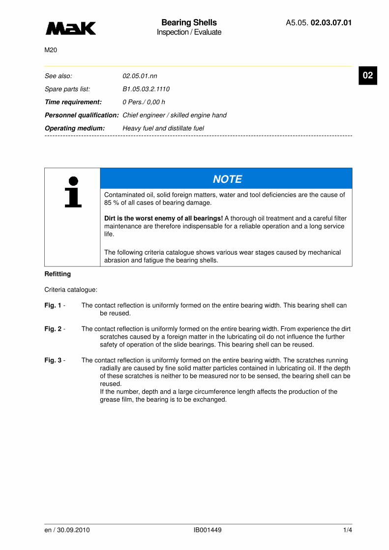
Bearing ShellsInspection / Evaluate
A5.05. 02.03.07.01
M20
02
-------
See also: 02.05.01.nn
Spare parts list: B1.05.03.2.1110
Time requirement: 0 Pers./ 0,00 h
Personnel qualification: Chief engineer / skilled engine hand
-------------------------------------------------------------------------------------------------------------------------
Operating medium: Heavy fuel and distillate fuel
Refitting
Criteria catalogue:
Fig. 1 - The contact reflection is uniformly formed on the entire bearing width. This bearing shell can be reused.
Fig. 2 - The contact reflection is uniformly formed on the entire bearing width. From experience the dirt scratches caused by a foreign matter in the lubricating oil do not influence the further safety of operation of the slide bearings. This bearing shell can be reused.
Fig. 3 - The contact reflection is uniformly formed on the entire bearing width. The scratches running radially are caused by fine solid matter particles contained in lubricating oil. If the depth of these scratches is neither to be measured nor to be sensed, the bearing shell can be reused.If the number, depth and a large circumference length affects the production of the grease film, the bearing is to be exchanged.
NOTE
Contaminated oil, solid foreign matters, water and tool deficiencies are the cause of 85 % of all cases of bearing damage.
Dirt is the worst enemy of all bearings! A thorough oil treatment and a careful filter maintenance are therefore indispensable for a reliable operation and a long service life.
The following criteria catalogue shows various wear stages caused by mechanical abrasion and fatigue the bearing shells.
en / 30.09.2010 IB001449 1/4
Bearing ShellsInspection / Evaluate
A5.05. 02.03.07.01
M20
02
ReplacementFig. 4 - The contact reflection shows the presence of heavy pressure on one bearing edge with scratches in the sliding surface made from aluminium alloy. This bearing shell is not reusable. The cause for this damage has to be determined and eliminated.
Fig. 5 - The contact reflection shows a large area of damage with various degrees of scratching. This bearing shell is not reusable. The cause for this slide bearing damage has to be determined and eliminated. Further bearing shells are to be inspected.
Fig. 6 - The load bearing area of the bearing shell shows breakages in the breaking metal, provoked by fatigue of the sliding surface made from aluminum alloy. Several bearing metal pieces are loose in the fatigue zone. The surface structure in the base of the breakage indicates a firm composition of steel and aluminum alloy. This bearing shell must be exchanged. Further shells are to be inspected.
en / 30.09.2010 IB001449 2/4

Bearing ShellsInspection / Evaluate
A5.05. 02.03.07.01
M20
02
en / 30.09.2010 IB001449 3/4

Bearing ShellsInspection / Evaluate
A5.05. 02.03.07.01
M20
02
en / 30.09.2010 IB001449 4/4
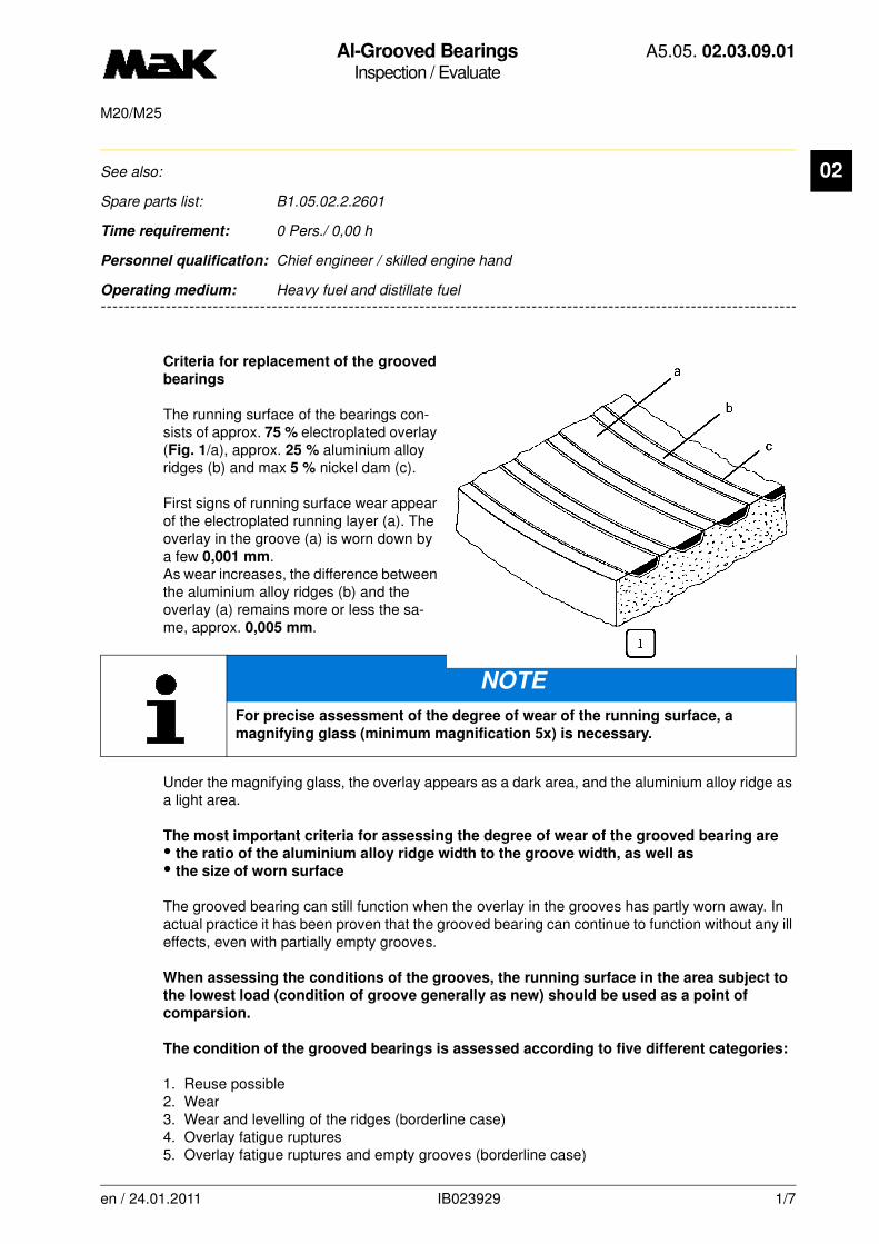
Al-Grooved BearingsInspection / Evaluate
A5.05. 02.03.09.01
M20/M25
02
-------
See also:
Spare parts list: B1.05.02.2.2601
Time requirement: 0 Pers./ 0,00 h
Personnel qualification: Chief engineer / skilled engine hand
-------------------------------------------------------------------------------------------------------------------------
Operating medium: Heavy fuel and distillate fuel
Criteria for replacement of the grooved
bearings
The running surface of the bearings con-sists of approx. 75 % electroplated overlay (Fig. 1/a), approx. 25 % aluminium alloy ridges (b) and max 5 % nickel dam (c).
First signs of running surface wear appear of the electroplated running layer (a). The overlay in the groove (a) is worn down by a few 0,001 mm.As wear increases, the difference between the aluminium alloy ridges (b) and the overlay (a) remains more or less the sa-me, approx. 0,005 mm.
Under the magnifying glass, the overlay appears as a dark area, and the aluminium alloy ridge as a light area.
The most important criteria for assessing the degree of wear of the grooved bearing are
• the ratio of the aluminium alloy ridge width to the groove width, as well as
• the size of worn surface
The grooved bearing can still function when the overlay in the grooves has partly worn away. In actual practice it has been proven that the grooved bearing can continue to function without any ill effects, even with partially empty grooves.
When assessing the conditions of the grooves, the running surface in the area subject to
the lowest load (condition of groove generally as new) should be used as a point of
comparsion.
The condition of the grooved bearings is assessed according to five different categories:
1. Reuse possible2. Wear3. Wear and levelling of the ridges (borderline case)4. Overlay fatigue ruptures5. Overlay fatigue ruptures and empty grooves (borderline case)
NOTE
For precise assessment of the degree of wear of the running surface, a
magnifying glass (minimum magnification 5x) is necessary.
en / 24.01.2011 IB023929 1/7
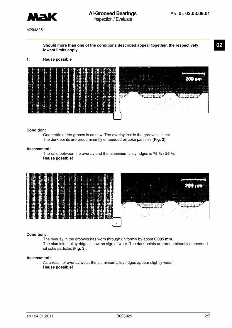
Al-Grooved BearingsInspection / Evaluate
A5.05. 02.03.09.01
M20/M25
02
Should more than one of the conditions described appear together, the respectivelylowest limits apply.
1. Reuse possible
Condition:
Geometrie of the groove is as new. The overlay inside the groove is intact.The dark points are predominantly embedded oil coke particles (Fig. 2).
Assessment:
The ratio between the overlay and the aluminium alloy ridges is 75 % / 25 %. Reuse possible!
Condition:
The overlay in the grooves has worn through uniformly by about 0,005 mm. The aluminium alloy ridges show no sign of wear. The dark points are predominantly embedded oil coke particles (Fig. 3).
Assessment:
As a result of overlay wear, the aluminium alloy ridges appear slightly wider. Reuse possible!
en / 24.01.2011 IB023929 2/7

Al-Grooved BearingsInspection / Evaluate
A5.05. 02.03.09.01
M20/M25
02
1.1 Reuse possibleCondition:
Small foreign particles spread over the entire running surface. No significant alteration of the alu-minium allow ridges (Fig. 4).
Assessment:
Reuse of the bearing shell is possible, since foreign particles are embedded in the grooves.
Condition:
The overlay has been locally “dragged” and “smeared” over the aluminium alloy ridges. The alu-minium alloy ridges can no longer be seen in some places.
Assessment:
Reuse of the bearing shell is possible.
en / 24.01.2011 IB023929 3/7

Al-Grooved BearingsInspection / Evaluate
A5.05. 02.03.09.01
M20/M25
02
2. WearCondition:
The bearing has in some places been worn down to such an extent that the bearing metal ridges and the overlay grooves have reached a ration of 1:1. The width of the bearing metal ridges has increased from 25 % (when new) to 50 %. Some overlay still exists in the grooves (Fig. 6).
Wear limits:
a) max. 30 % of circumferenceb) max. 70 % of widthc) max. 50 % of circumferenced) max. 35 % of width
Assessment:
Bearing is operative. Should a condition of wear as shown in 3 be expected within the next in-spection interval, bearing has to be replaced for safety reason.
Overlay-groove
Bearing metal ridge
= Wear 1:1
en / 24.01.2011 IB023929 4/7
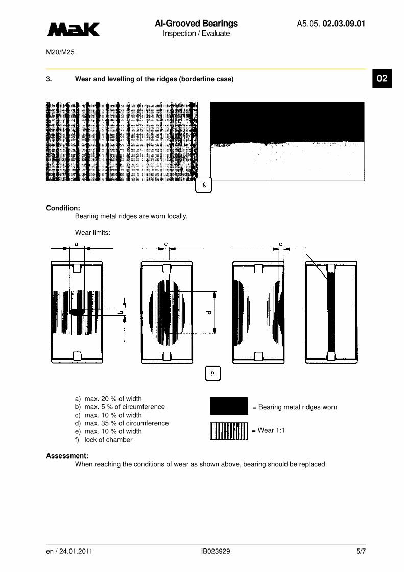
Al-Grooved BearingsInspection / Evaluate
A5.05. 02.03.09.01
M20/M25
02
3. Wear and levelling of the ridges (borderline case)Condition:
Bearing metal ridges are worn locally.
Wear limits:
a) max. 20 % of widthb) max. 5 % of circumferencec) max. 10 % of widthd) max. 35 % of circumferencee) max. 10 % of widthf) lock of chamber
Assessment:
When reaching the conditions of wear as shown above, bearing should be replaced.
= Bearing metal ridges worn
= Wear 1:1
en / 24.01.2011 IB023929 5/7
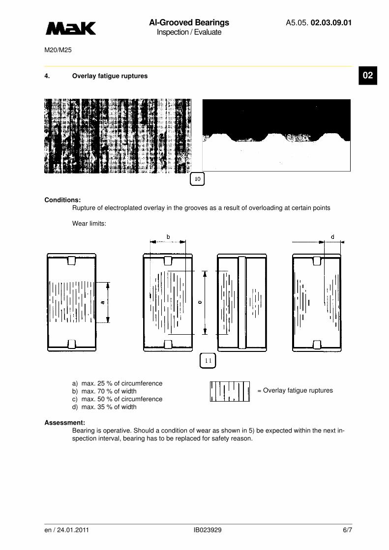
Al-Grooved BearingsInspection / Evaluate
A5.05. 02.03.09.01
M20/M25
02
4. Overlay fatigue rupturesConditions:
Rupture of electroplated overlay in the grooves as a result of overloading at certain points
Wear limits:
a) max. 25 % of circumferenceb) max. 70 % of widthc) max. 50 % of circumferenced) max. 35 % of width
Assessment:
Bearing is operative. Should a condition of wear as shown in 5) be expected within the next in-spection interval, bearing has to be replaced for safety reason.
= Overlay fatigue ruptures
en / 24.01.2011 IB023929 6/7

Al-Grooved BearingsInspection / Evaluate
A5.05. 02.03.09.01
M20/M25
02
5. Overlay fatique ruptures and empty groovesCondition:
In certain areas empty grooves are visible after washing out the ruptured overlay.
Wear limits:
a) max. 40 % of widthb) max. 10 % of circumferendec) max. 30 % of widthd) max. 40 % of circumferencee) max. 15 % of width
Assessment:
When reaching the condition described above, bearing must be replaced.
= Empty grooves
= Bearing metal ridges worn
= Overlay fatique ruptures
en / 24.01.2011 IB023929 7/7
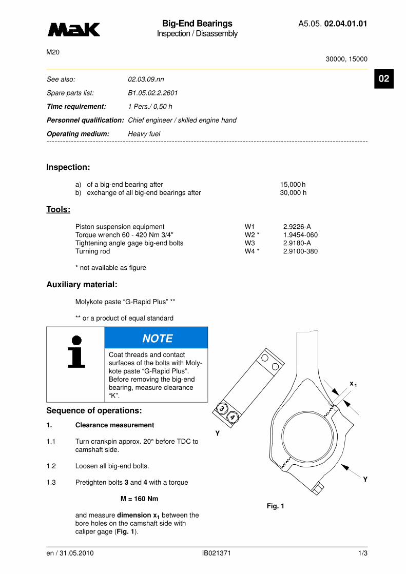
Big-End BearingsInspection / Disassembly
A5.05. 02.04.01.01
30000, 15000M20
02
-------
See also: 02.03.09.nn
Spare parts list: B1.05.02.2.2601
Time requirement: 1 Pers./ 0,50 h
Personnel qualification: Chief engineer / skilled engine hand
-------------------------------------------------------------------------------------------------------------------------
Operating medium: Heavy fuel
Inspection:
a) of a big-end bearing after 15,000 h b) exchange of all big-end bearings after 30,000 h
Tools:
Piston suspension equipment W1 2.9226-ATorque wrench 60 - 420 Nm 3/4" W2 * 1.9454-060Tightening angle gage big-end bolts W3 2.9180-ATurning rod W4 * 2.9100-380
* not available as figure
Auxiliary material:
Molykote paste “G-Rapid Plus” **
** or a product of equal standard
Sequence of operations:
1. Clearance measurement
1.1 Turn crankpin approx. 20° before TDC to camshaft side.
1.2 Loosen all big-end bolts.
1.3 Pretighten bolts 3 and 4 with a torque
M = 160 Nm
and measure dimension x1 between the bore holes on the camshaft side with caliper gage (Fig. 1).
NOTE
Coat threads and contact surfaces of the bolts with Moly-kote paste “G-Rapid Plus”. Before removing the big-end bearing, measure clearance “K”.
Y
Y
4
x 1
Fig. 1
3
en / 31.05.2010 IB021371 1/3

Big-End BearingsInspection / Disassembly
A5.05. 02.04.01.01
30000, 15000M20
02
1.4 Tighten bolts 1 and 2 twice in the sequence 1 - 2 - 1 - 2 with a torqueM = 160 Nm.
1.5 Mark the bolt position or put on a tightening angle gauge
1.6 Clamp the bolts tight in the sequence 3 - 4
- 1 - 2 with a torque
M = 350 Nm
corresponding to a minimum tightening angle of bolts:
1 and 2 of min. 13°°°° - 16
3 and 4 of min. 17°°°° - 19°°°°
1.7 Measure dimension x2 between the bore holes on the camshaft side and determine the differential dimension
x1 - x2 = clearance.
Clearance Limit valuemm mm
0.45 - 0.65 0.35
If the limit value is not reached, renew bearing shells pairwise and mark both halves in accordance with the numbers of impacts cylinder No., connecting rod and bearing cap (W).
CAUTION
the minimum tightening angle is to be kept
x 2
Z
Z
Fig. 2
34
21
W
W3
W
en / 31.05.2010 IB021371 2/3

Big-End BearingsInspection / Disassembly
A5.05. 02.04.01.01
30000, 15000M20
02
2. Removing the big-end bearing cap2.1 Turn crankshaft into a convenient position for removing (crankpin 20° before of TDC to the camshaft side).
2.2 Loosen big-end bearing bolts and screw out off connecting-rod big end.
2.3 Lift bearing cap out of the crankcase.
2.4 Check the toothing in the joint faces of connecting rod, big-end bearing cap and thread for damage.
3. Removing the bearing shells
3.1 Move piston to TDC position, fit piston suspension device (Fig. 3/W1) and move crankshaft carefully to camshaft side until the piston rests on the suspension device and the crankpin swings out of the connecting-rod big end.
3.2 Remove bearing shells from crankpins.
3.3 Bearing shells, rating/replacement criteria:
• AL groove bearing: 02.03.09.nn.
W1
Fig. 3
en / 31.05.2010 IB021371 3/3
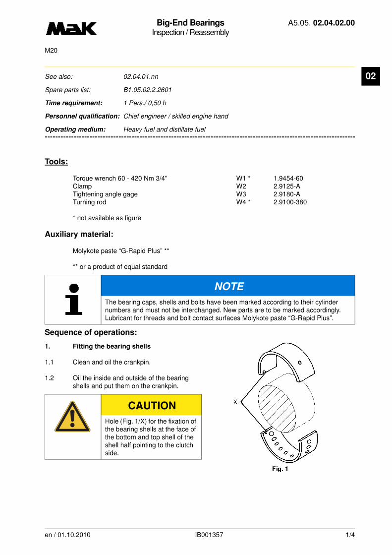
Big-End BearingsInspection / Reassembly
A5.05. 02.04.02.00
M20
02
-------
See also: 02.04.01.nn
Spare parts list: B1.05.02.2.2601
Time requirement: 1 Pers./ 0,50 h
Personnel qualification: Chief engineer / skilled engine hand
-------------------------------------------------------------------------------------------------------------------------
Operating medium: Heavy fuel and distillate fuel
Tools:
Torque wrench 60 - 420 Nm 3/4" W1 * 1.9454-60Clamp W2 2.9125-A Tightening angle gage W3 2.9180-A Turning rod W4 * 2.9100-380
* not available as figure
Auxiliary material:
Molykote paste “G-Rapid Plus” **
** or a product of equal standard
Sequence of operations:
1. Fitting the bearing shells
1.1 Clean and oil the crankpin.
1.2 Oil the inside and outside of the bearing shells and put them on the crankpin.
NOTE
The bearing caps, shells and bolts have been marked according to their cylinder numbers and must not be interchanged. New parts are to be marked accordingly. Lubricant for threads and bolt contact surfaces Molykote paste “G-Rapid Plus”.
CAUTION
Hole (Fig. 1/X) for the fixation of the bearing shells at the face of the bottom and top shell of the shell half pointing to the clutch side.
en / 01.10.2010 IB001357 1/4
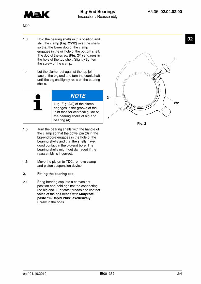
Big-End BearingsInspection / Reassembly
A5.05. 02.04.02.00
M20
02
1.3 Hold the bearing shells in this position and shift the clamp (Fig. 2/W2) over the shells so that the lower dog of the clamp engages in the oil hole of the bottom shell. The dog of the screw (Fig. 2/1) engages in the hole of the top shell. Slightly tighten the screw of the clamp.1.4 Let the clamp rest against the top joint face of the big end and turn the crankshaft until the big end lightly rests on the bearing shells.
1.5 Turn the bearing shells with the handle of the clamp so that the dowel pin (3) in the big-end bore engages in the hole of the bearing shells and that the shells have good contact in the big-end bore. The bearing shells might get damaged if the reassembly is incorrect.
1.6 Move the piston to TDC. remove clamp and piston suspension device.
2. Fitting the bearing cap.
2.1 Bring bearing cap into a convenient position and hold against the connecting-rod big end. Lubricate threads and contact faces of the bolt heads with Molykote
paste “G-Rapid Plus” exclusively. Screw in the bolts.
NOTE
Lug (Fig. 2/2) of the clamp engages in the groove of the joint face for centrical guide of the bearing shells of big-end bearing (4).
Fig. 2
3
2
1
W2
en / 01.10.2010 IB001357 2/4
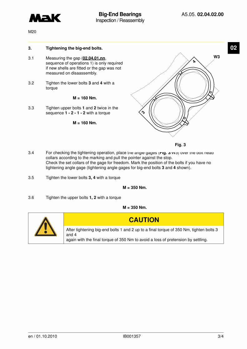
Big-End BearingsInspection / Reassembly
A5.05. 02.04.02.00
M20
02
3. Tightening the big-end bolts.3.1 Measuring the gap (02.04.01.nn, sequence of operations 1) is only required if new shells are fitted or the gap was not measured on disaassembly.
3.2 Tighten the lower bolts 3 and 4 with a torque
M = 160 Nm.
3.3 Tighten upper bolts 1 and 2 twice in the sequence 1 - 2 - 1 - 2 with a torque
M = 160 Nm.
3.4 For checking the tightening operation, place the angle gages (Fig. 3/W3) over the bolt head collars according to the marking and pull the pointer against the stop. Check the set collars of the gage for freedom. Mark the position of the bolts if you have no tightening angle gage (tightening angle gages for big-end bolts 3 and 4 shown).
3.5 Tighten the lower bolts 3, 4 with a torque
M = 350 Nm.
3.6 Tighten the upper bolts 1, 2 with a torque
M = 350 Nm.
CAUTION
After tightening big-end bolts 1 and 2 up to a final torque of 350 Nm, tighten bolts 3 and 4again with the final torque of 350 Nm to avoid a loss of pretension by settling.
Fig. 3
W3
3
4
en / 01.10.2010 IB001357 3/4

Big-End BearingsInspection / Reassembly
A5.05. 02.04.02.00
M20
02
3.7 Tightening check
3.7.1 Upper bolts 1 and 2: The maximum pointer must have been pulled beyond the angle marking. When checking without gage, the bolts must have turned through an angle of 13°°°° - 16°°°°.
3.7.2 Lower bolts 3 and 4: The maximum pointer must have passed the angle marking or the bolts must have turned through 17°°°° - 19.
NOTE
If these angles are not reached, undo the bolts with the ratchet handle (02.04.01.nn)
and check the parts for damage. For this, grease the threads and the contact faces of the bolts again with Molykote paste “G-Rapid Plus”.
en / 01.10.2010 IB001357 4/4
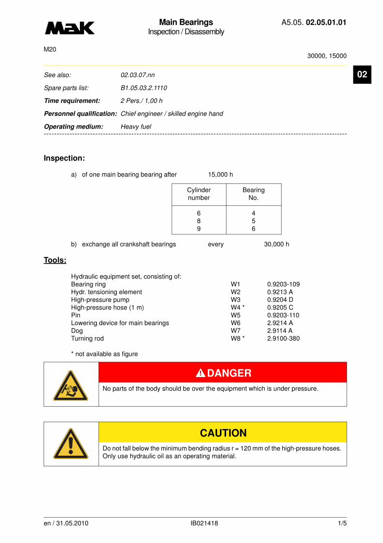
Main BearingsInspection / Disassembly
A5.05. 02.05.01.01
30000, 15000M20
02
-------
See also: 02.03.07.nn
Spare parts list: B1.05.03.2.1110
Time requirement: 2 Pers./ 1,00 h
Personnel qualification: Chief engineer / skilled engine hand
-------------------------------------------------------------------------------------------------------------------------
Operating medium: Heavy fuel
Inspection:
a) of one main bearing bearing after 15,000 h
Cylinder Bearingnumber No.
6 48 59 6
b) exchange all crankshaft bearings every 30,000 h
Tools:
Hydraulic equipment set, consisting of:Bearing ring W1 0.9203-109 Hydr. tensioning element W2 0.9213 A High-pressure pump W3 0.9204 D High-pressure hose (1 m) W4 * 0.9205 CPin W5 0.9203-110Lowering device for main bearings W6 2.9214 ADog W7 2.9114 ATurning rod W8 * 2.9100-380
* not available as figure
DANGER
No parts of the body should be over the equipment which is under pressure.
CAUTION
Do not fall below the minimum bending radius r = 120 mm of the high-pressure hoses. Only use hydraulic oil as an operating material.
en / 31.05.2010 IB021418 1/5
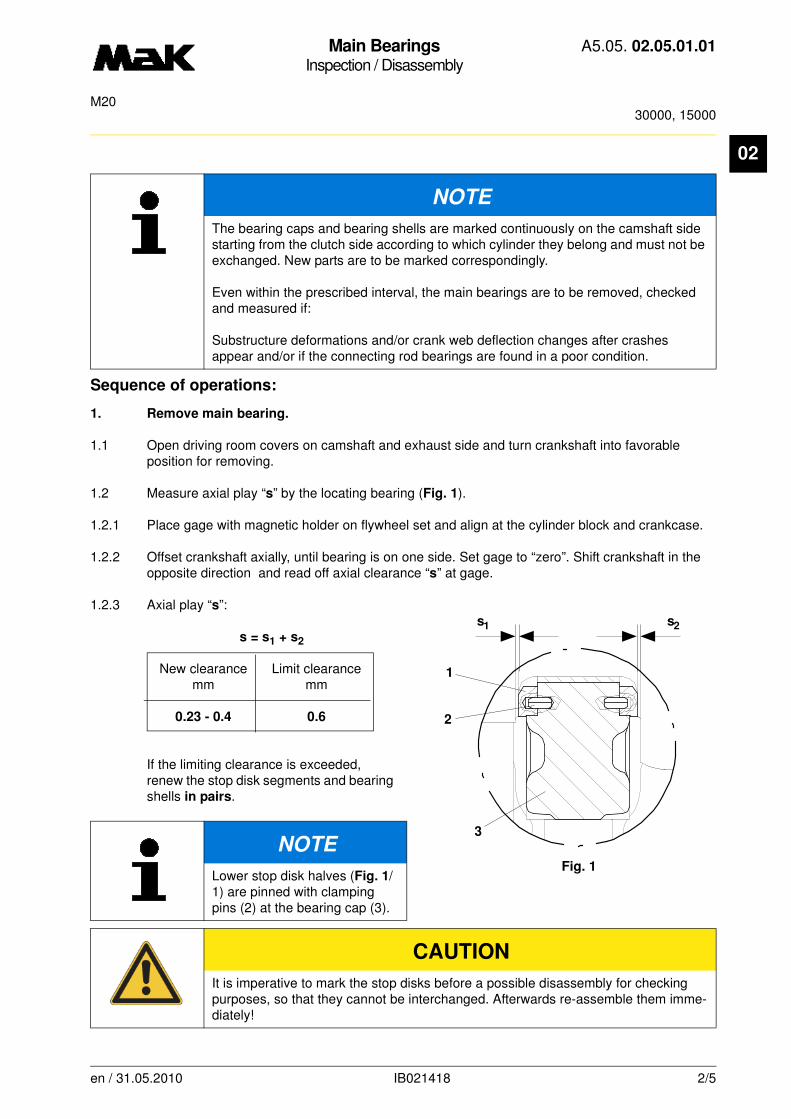
Main BearingsInspection / Disassembly
A5.05. 02.05.01.01
30000, 15000M20
02
Sequence of operations:
1. Remove main bearing.
1.1 Open driving room covers on camshaft and exhaust side and turn crankshaft into favorable position for removing.
1.2 Measure axial play “s” by the locating bearing (Fig. 1).
1.2.1 Place gage with magnetic holder on flywheel set and align at the cylinder block and crankcase.
1.2.2 Offset crankshaft axially, until bearing is on one side. Set gage to “zero”. Shift crankshaft in the opposite direction and read off axial clearance “s” at gage.
1.2.3 Axial play “s”:
s = s1 + s2
New clearance Limit clearancemm mm
0.23 - 0.4 0.6
If the limiting clearance is exceeded, renew the stop disk segments and bearing shells in pairs.
NOTE
The bearing caps and bearing shells are marked continuously on the camshaft side starting from the clutch side according to which cylinder they belong and must not be exchanged. New parts are to be marked correspondingly.
Even within the prescribed interval, the main bearings are to be removed, checked and measured if:
Substructure deformations and/or crank web deflection changes after crashes appear and/or if the connecting rod bearings are found in a poor condition.
NOTE
Lower stop disk halves (Fig. 1/1) are pinned with clamping pins (2) at the bearing cap (3).
CAUTION
It is imperative to mark the stop disks before a possible disassembly for checking purposes, so that they cannot be interchanged. Afterwards re-assemble them imme-diately!
s1 s2
Fig. 1
3
2
1
en / 31.05.2010 IB021418 2/5

Main BearingsInspection / Disassembly
A5.05. 02.05.01.01
30000, 15000M20
02
1.3 Loosen bearing bolts with hydraulic tightening equipment.1.3.1 Remove hexagon screws (Fig. 2/11) of the main bearing which is to be removed.
1.3.2 Place bearing ring (W1) over the round nut (12) and turn hydraulic tensioning element (W2) on bearing bolt (13) and screw against bearing ring. Make sure that the slots (14) are easily accessi-ble.
1.3.3 Link hydraulic tensioning element (W2) with high-pressure pump (W3) via high-pressure hose (W4) and press onto block length (Valve [Z] open at the high-pressure pump).
1.3.4 Set a gap “s” of 2.5 mm (Fig. 3) between bearing ring and tensioning element.
1.3.5 Stretch both bearing bolts in one work se-quence with
p = 750 bar
and loosen round nuts (12) with pin (W5).
NOTE
Prestress bearing bolts by approx. 50 bar more if required. If the pressure is increased further the round nut might stick due to stretching of the bolt thread.
W4
Z W3
11
14
W1
12
W2
13
Fig. 2
sW5
12
Fig. 3
en / 31.05.2010 IB021418 3/5
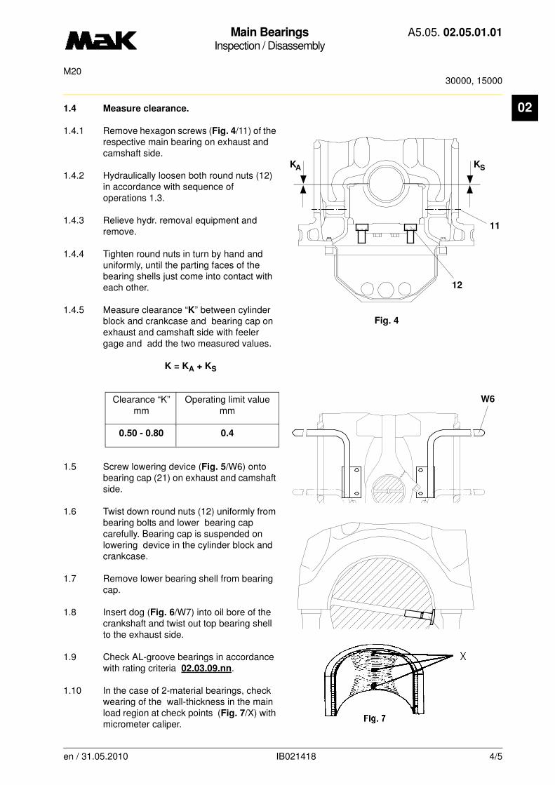
Main BearingsInspection / Disassembly
A5.05. 02.05.01.01
30000, 15000M20
02
1.4 Measure clearance.1.4.1 Remove hexagon screws (Fig. 4/11) of the respective main bearing on exhaust and camshaft side.
1.4.2 Hydraulically loosen both round nuts (12) in accordance with sequence of operations 1.3.
1.4.3 Relieve hydr. removal equipment and remove.
1.4.4 Tighten round nuts in turn by hand and uniformly, until the parting faces of the bearing shells just come into contact with each other.
1.4.5 Measure clearance “K” between cylinder block and crankcase and bearing cap on exhaust and camshaft side with feeler gage and add the two measured values.
K = KA + KS
Clearance “K” Operating limit valuemm mm
0.50 - 0.80 0.4
1.5 Screw lowering device (Fig. 5/W6) onto bearing cap (21) on exhaust and camshaft side.
1.6 Twist down round nuts (12) uniformly from bearing bolts and lower bearing cap carefully. Bearing cap is suspended on lowering device in the cylinder block and crankcase.
1.7 Remove lower bearing shell from bearing cap.
1.8 Insert dog (Fig. 6/W7) into oil bore of the crankshaft and twist out top bearing shell to the exhaust side.
1.9 Check AL-groove bearings in accordance with rating criteria 02.03.09.nn.
1.10 In the case of 2-material bearings, check wearing of the wall-thickness in the main load region at check points (Fig. 7/X) with micrometer caliper.
Fig. 4
12
KA
11
KS
W6
21
12
Fig. 5
Fig. 6
W7
en / 31.05.2010 IB021418 4/5

Main BearingsInspection / Disassembly
A5.05. 02.05.01.01
30000, 15000M20
02
Wear = new dimension -actual dimension
New dimension: 4.927-0.015 mm
In the case of a wear of > 0.05 mm the bearing shells are to be changed. Further rating criteria, 02.03.07.nn.
CAUTION
If a bearing shell has to be changed during inspection, the adjacent bearings are also to be checked.
en / 31.05.2010 IB021418 5/5
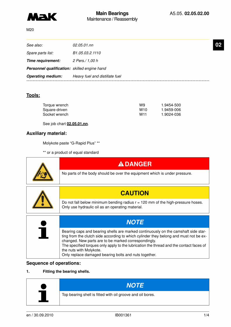
Main BearingsMaintenance / Reassembly
A5.05. 02.05.02.00
M20
02
-------
See also: 02.05.01.nn
Spare parts list: B1.05.03.2.1110
Time requirement: 2 Pers./ 1,00 h
Personnel qualification: skilled engine hand
-------------------------------------------------------------------------------------------------------------------------
Operating medium: Heavy fuel and distillate fuel
Tools:
Torque wrench W9 1.9454-500Square-driven W10 1.9459-006Socket wrench W11 1.9024-036
See job chart 02.05.01.nn.
Auxiliary material:
Molykote paste “G-Rapid Plus” **
** or a product of equal standard
Sequence of operations:
1. Fitting the bearing shells.
DANGER
No parts of the body should be over the equipment which is under pressure.
CAUTION
Do not fall below minimum bending radius r = 120 mm of the high-pressure hoses. Only use hydraulic oil as an operating material.
NOTE
Bearing caps and bearing shells are marked continuously on the camshaft side star-ting from the clutch side according to which cylinder they belong and must not be ex-changed. New parts are to be marked correspondingly. The specified torques only apply to the lubrication the thread and the contact faces of the nuts with Molykote. Only replace damaged bearing bolts and nuts together.
NOTE
Top bearing shell is fitted with oil groove and oil bores.
en / 30.09.2010 IB001361 1/4

Main BearingsMaintenance / Reassembly
A5.05. 02.05.02.00
M20
02
1.1 Lubricate working face of the top bearing shell well, wipe bearing back dry and press bearing shell into the bearing so far that the dog (Fig. 1/W7) can be inserted into the oil bore of the crankshaft.1.2 Twist in top bearing shell. Thereby, maintain central position of the bearing shell. The fixing lug must slide into the guide groove of the bearing seat.
1.3 Lubricate working face of the lower bearing shell, wipe bearing back dry and insert into bearing cap.
2. Tightening of the bearing shells.
2.1 Lift the bearing cap with the aid of the lowering device (Fig. 2/W6) over the bearing bolts and screw round nuts (1) uniformly on bearing bolts and tighten hand-tight with pin (W5). Remove lowering device (W6).
CAUTION
The bearing guide groove for the lower shell is on the cams-haft side. Observe fixing pin on the exhaust gas side in the case of locating bearing cap.
NOTE
During the installation of new bearing shells, the clearance “K” and in the case of locating bearings, the axial play (02.05.01.nn) is to be measu-red.
Fig. 1
W7
W6
1
Fig. 2
en / 30.09.2010 IB001361 2/4
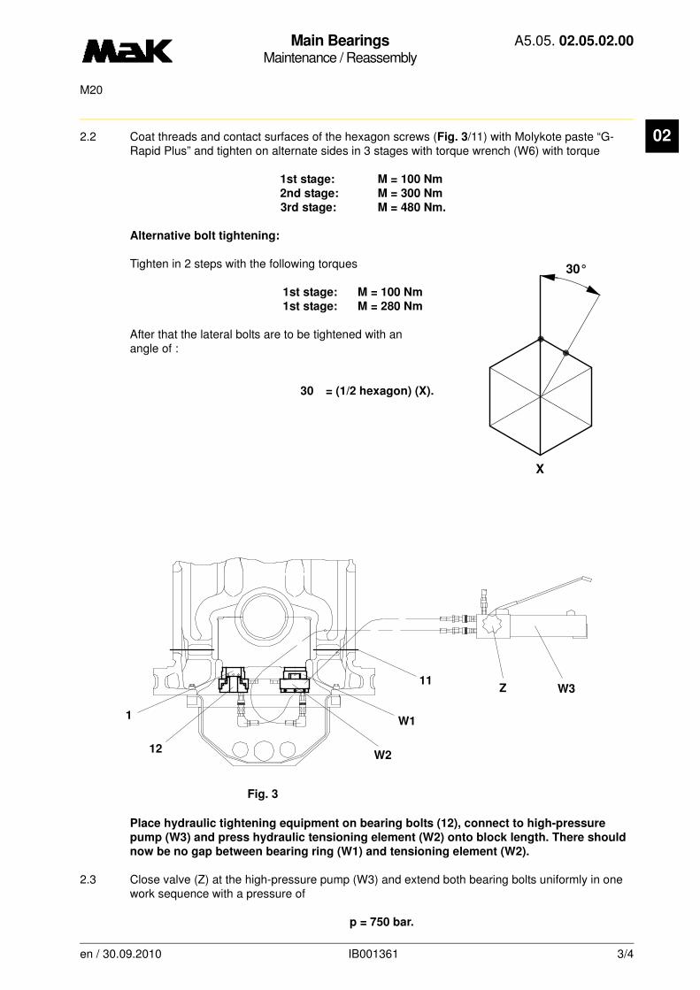
Main BearingsMaintenance / Reassembly
A5.05. 02.05.02.00
M20
02
2.2 Coat threads and contact surfaces of the hexagon screws (Fig. 3/11) with Molykote paste “G-Rapid Plus” and tighten on alternate sides in 3 stages with torque wrench (W6) with torque1st stage: M = 100 Nm
2nd stage: M = 300 Nm
3rd stage: M = 480 Nm.
Alternative bolt tightening:
Tighten in 2 steps with the following torques
1st stage: M = 100 Nm
1st stage: M = 280 Nm
After that the lateral bolts are to be tightened with an angle of :
30 = (1/2 hexagon) (X).
Place hydraulic tightening equipment on bearing bolts (12), connect to high-pressure
pump (W3) and press hydraulic tensioning element (W2) onto block length. There should
now be no gap between bearing ring (W1) and tensioning element (W2).
2.3 Close valve (Z) at the high-pressure pump (W3) and extend both bearing bolts uniformly in one work sequence with a pressure of
p = 750 bar.
X
30°
Fig. 3
1
12W2
W1
11Z W3
en / 30.09.2010 IB001361 3/4
Main BearingsMaintenance / Reassembly
A5.05. 02.05.02.00
M20
02
2.4 Firmly tighten round nuts (1) uniformly with pin (W5).
3. Inspection:
Lower pressure by 50 bar. Round nuts (1) should no longer be able to be loosened by hand.
4. Lower pressure at valve (Z) and remove hydraulic tightening equipment.
5. Carry out lube oil flow-through inspection.
CAUTION
The pressure must remain constant if the pump is not activated. Otherwise tightening errors occur.
en / 30.09.2010 IB001361 4/4
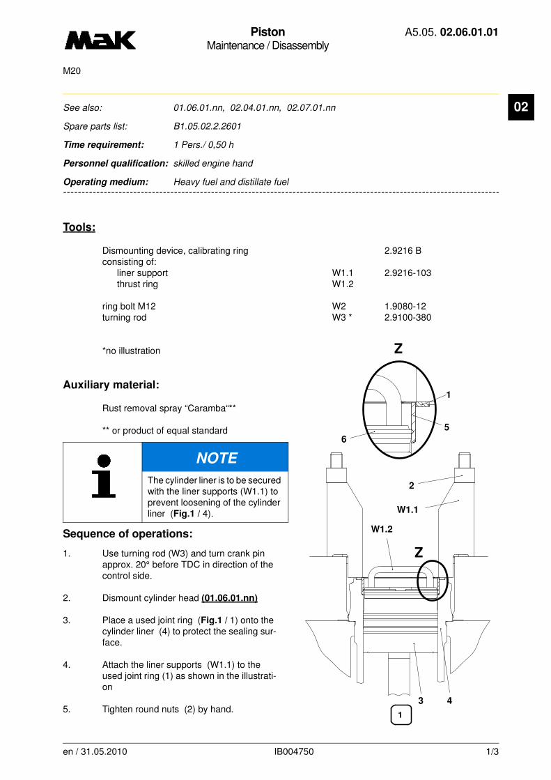
PistonMaintenance / Disassembly
A5.05. 02.06.01.01
M20
02
-------
See also: 01.06.01.nn, 02.04.01.nn, 02.07.01.nn
Spare parts list: B1.05.02.2.2601
Time requirement: 1 Pers./ 0,50 h
Personnel qualification: skilled engine hand
-------------------------------------------------------------------------------------------------------------------------
Operating medium: Heavy fuel and distillate fuel
Tools:
Dismounting device, calibrating ring 2.9216 Bconsisting of:
liner support W1.1 2.9216-103thrust ring W1.2
ring bolt M12 W2 1.9080-12turning rod W3 * 2.9100-380
*no illustration
Auxiliary material:
Rust removal spray “Caramba“**
** or product of equal standard
Sequence of operations:
1. Use turning rod (W3) and turn crank pin approx. 20° before TDC in direction of the control side.
2. Dismount cylinder head (01.06.01.nn)
3. Place a used joint ring (Fig.1 / 1) onto the cylinder liner (4) to protect the sealing sur-face.
4. Attach the liner supports (W1.1) to the used joint ring (1) as shown in the illustrati-on
5. Tighten round nuts (2) by hand.
NOTE
The cylinder liner is to be secured with the liner supports (W1.1) to prevent loosening of the cylinder liner (Fig.1 / 4).
Z
5
1
43
6
W1.2
Z
2
W1.1
1
en / 31.05.2010 IB004750 1/3
PistonMaintenance / Disassembly
A5.05. 02.06.01.01
M20
02
6. Fill the ring gap between piston (3)and cylinder liner (4) with grease.
7. Carefully scrape off and completely remove carbon deposits in the liner (4) ) between TDC of the first piston ring and the lower edge of the calibrating ring (5).
8. Clean the groove in the calibrating ring (5).
9. Spray a thin film of rust removal spray „Caramba“ in the ring gap between calibrating ring (5) and liner (4).
10. Allow the rust removal spray to react.
11. To loosen the calibrating ring (5) slightly beat it with a copper hammer until you can turn the guide of the calibrating ring by hand.
12. Turn piston (3) with turning rod (W3) approx. 50° to TDC.
13. Insert thrust ring (W1.2) and compressed snap ring (6) until the lower edge rests on the piston.
14. Carefully turn piston (3) and thrust ring (W1.2) upwards until the snap ring (6) is engaged in the groove of the calibrating ring (5).
15. Turn piston (3) further upwards and press out the calibrating ring (5. ). Watch the position of the calibrating ring.
16. Remove calibrating ring (5) and thrust ring (W1.2).
17. Dismount big-end bearing cover (02.04.01.nn).
18. Turn piston (3) in TDC position, re-tap threaded hole (M12, 11 mm deep) in piston head.
CAUTION
The sealing surfaces of the cylinder liner have to be protected against damage!
NOTE
Do not damage the surface of the liner !
CAUTION
In case the calibrating ring is tilted, you have to lower the piston and align the calibra-ting ring.The connecting-rod must not strike on the crank pin. Turn crank pin aside, if neces-sary.
en / 31.05.2010 IB004750 2/3

PistonMaintenance / Disassembly
A5.05. 02.06.01.01
M20
02
19. Screw the ring bolt (Fig. 2 / W2)into the piston .20. Mount the crane to the ring bolt (W2).
21. Slowly pull out the piston; carefully insert con-rod foot into the liner and remove big-end bearing shells.
22. Place piston in a suitable device. W2
2
en / 31.05.2010 IB004750 3/3

PistonMaintenance / Disassembly
A5.05. 02.06.01.02
M20
02
-------
See also: 01.06.01.nn, 02.04.01.nn, 02.07.01.nn
Spare parts list: B1.05.02.2.2601
Time requirement: 1 Pers./ 0,50 h
Personnel qualification: skilled engine hand
-------------------------------------------------------------------------------------------------------------------------
Operating medium: Heavy fuel and distillate fuel
Tools:
Sleeve support W1 2.9216-103Eye screw M12 W2 1.9080-012Turning rod W3* 2.9100-380Disassembly unit W4 2.9216 C*not shown
Aids:
“Caramba“** deruster
**or equivalent product
NOTE
To prevent loosening of the cylinder sleeve (4), it should also be secured with the sleeve supports (W1).
Y
W2
4
1
6
W45
Z
Y
Z
2
3
W1
en / 05.10.2010 IB004756 1/3

PistonMaintenance / Disassembly
A5.05. 02.06.01.02
M20
02
Procedure:1. Turn the crank pin with the turning rod (W3) approx. 20°in front of the top section to the control si-de.
2. Remove the cylinder head (01.06.01.nn)
3. Place a used sealing ring (1) as sealing surface protection on the cylinder sleeve (4).
4. Position sleeve supports (W1) on the used sealing ring (1) as shown in the drawing.
5. Hand-tighten the round nuts (2).
6. Fill the annular gap between the piston (3) and the cylinder sleeve (4) with grease.
7. Carefully scrape off the accumulated coke in the cylinder sleeve between the top section of the 1st piston ring and the lower edge of the calibration ring (5) and remove so that the shoulder of the calibration ring can be clearly felt all round.
8. Lightly spray the annular gap between the calibration ring and the cylinder sleeve (4) with deru-ster.
9. Allow the deruster to take effect.
10. Insert the disassembly unit (W4) so that the recess (Z) is inside the calibration ring (5).
11. Lightly tension the disassembly unit (W4) by turning the spindle nut (6).
12. Force out the calibration ring (5) by turning up the piston (3) into the top position.
13. Recut the threaded hole (M12, 11 mm deep) in the top of the piston.
14. Insert the eye screw (W2) in the piston (3).
15. Remove the cover of the connecting rod bearing (02.04.01.nn).
16. Attach the crane to the eye screw (W2) and slowly remove the piston (3).
CAUTION
The sealing surfaces of the sleeves must be protected from damage!
NOTE
Take care not to damage the cylinder sleeve surface!
en / 05.10.2010 IB004756 2/3
PistonMaintenance / Disassembly
A5.05. 02.06.01.02
M20
02
17. Drop the piston in the appropriate direction.
CAUTION
Make sure that the calibration ring is drawn out smoothly when removing the piston.If the calibration ring becomes tilted, lower the piston and align the calibration ring.The connecting rod must not strike the crank pin; if necessary turn the crank pin to the side.
en / 05.10.2010 IB004756 3/3

Piston Rings and GroovesInspection / Checking
A5.05. 02.07.01.01
30000, 7500M20
02
-------
See also: 01.06.01.nn, 02.04.01.nn, 02.06.01.nn
Spare parts list: B1.05.02.2.2617
Time requirement: 1 Pers./ 0,50 h
Personnel qualification: Chief engineer / skilled engine hand
-------------------------------------------------------------------------------------------------------------------------
Operating medium: Heavy fuel
Inspection:
of one piston and its rings after 7,500 h
Maintenance:
of all pistons and their rings after 30,000 h
Tools:
Piston ring expander W1 2.9227-A
Sequence of operations:
1. Piston inspection (7,500 h)
1.1 Open all crankcase doors.
1.2 Check the running surfaces of the cylinder liners from the crank chamber.
1.3 Draw the piston from the liner with worst running pattern (02.06.01.nn). Draw the other pistons too, if the piston rings are stuck or rotten.
NOTE
f the running surfaces of all cylinder liners are without scores or high spots or any other damage and if the parts of the drawn piston are in proper condition, all piston rings free and no heavy wear can be detected, the inspection of the others pistons can be postponed to a later date, but not beyond a maximum of 30,000 operating hours. During the inspection, pay special attention to any sharp edges of the rings, ring tension or rings sticking due to carbon deposits.
Do not remove graphite coating on the piston skirt.
After fitting new piston rings, the engine must be driven in according to the driving-in regulation A3.10.01.nn!
Built-up pistons with chrome-plated 1st ring groove may only be reconditioned by the manufacturer.
en / 31.05.2010 IB021477 1/3

Piston Rings and GroovesInspection / Checking
A5.05. 02.07.01.01
30000, 7500M20
02
1.4 Remove the piston rings only with the correct tool (Fig. 1/W1). Maintain previous position of the rings referring to the mounting position of the piston given in the measuring sheet.1.5 Clean piston rings.
1.6 Check the the chrome layer for wear, especially at the cut and at the opposite side. Renew all rings of this piston even if only parts of the chrome layer is no longer visible.
If the chrome layer of one piston ring has been worn, check the rings of all pistons.
1.7 Clean the piston, ring grooves and oil return holes for the scraper scraper ring.
1.8 Smooth slight friction and seizing marks with an oily fine emery cloth or fine carborundum stone. Renew the piston in case of heavy damage or deep scores.
1.9 Measure the groove width hN (Fig. 2) in the front area of the groove in longitudinal and transverse directions of the engine. When exceeding the limits, have the ring grooves reconditioned by MaK.
1.10 Measure the ring thickness hR (Fig. 2) at 4 different points.
hN1 = newhN2 = worn
en / 31.05.2010 IB021477 2/3

Piston Rings and GroovesInspection / Checking
A5.05. 02.07.01.01
30000, 7500M20
02
1.11 Determine the clearance by calculation and check it against the table.Ring thicknes hR Groove width hN Limit of hN - hRGroove Nominal Wear limit mm
mm mm
1 – 3 4.95 5.6 0.65
4 6 6.5 0.5
1.12 Fit piston rings with the marking facing upwards (Fig. 3/X) and with the ring stops into the ring grooves alternatingly opposite in engine longitudinal direction.
2. Maintenance (30,000 h)
2.1 Draw all pistons (02.06.01.nn).
2.2 Check the state of lubrication and appearance of the running surface of the piston and clean it.
2.3 Remove the piston rings with piston ring expander (Fig. 1/W1). Maintain previous position of the rings referring to the mounting position of the piston given in the measuring sheet.
2.4 Clean all ring grooves.
2.5 Measure the groove width hN in accordance with sequence of operations 1.9.
2.6 Renew all compression and scraper rings.
2.6.1 Fit piston rings with the marking facing
upwards (Fig. 3/X) and with the ring
stops into the ring grooves
alternatingly opposite in engine
longitudinal direction.
2.7 Fit all pistons (02.06.02.nn).
en / 31.05.2010 IB021477 3/3
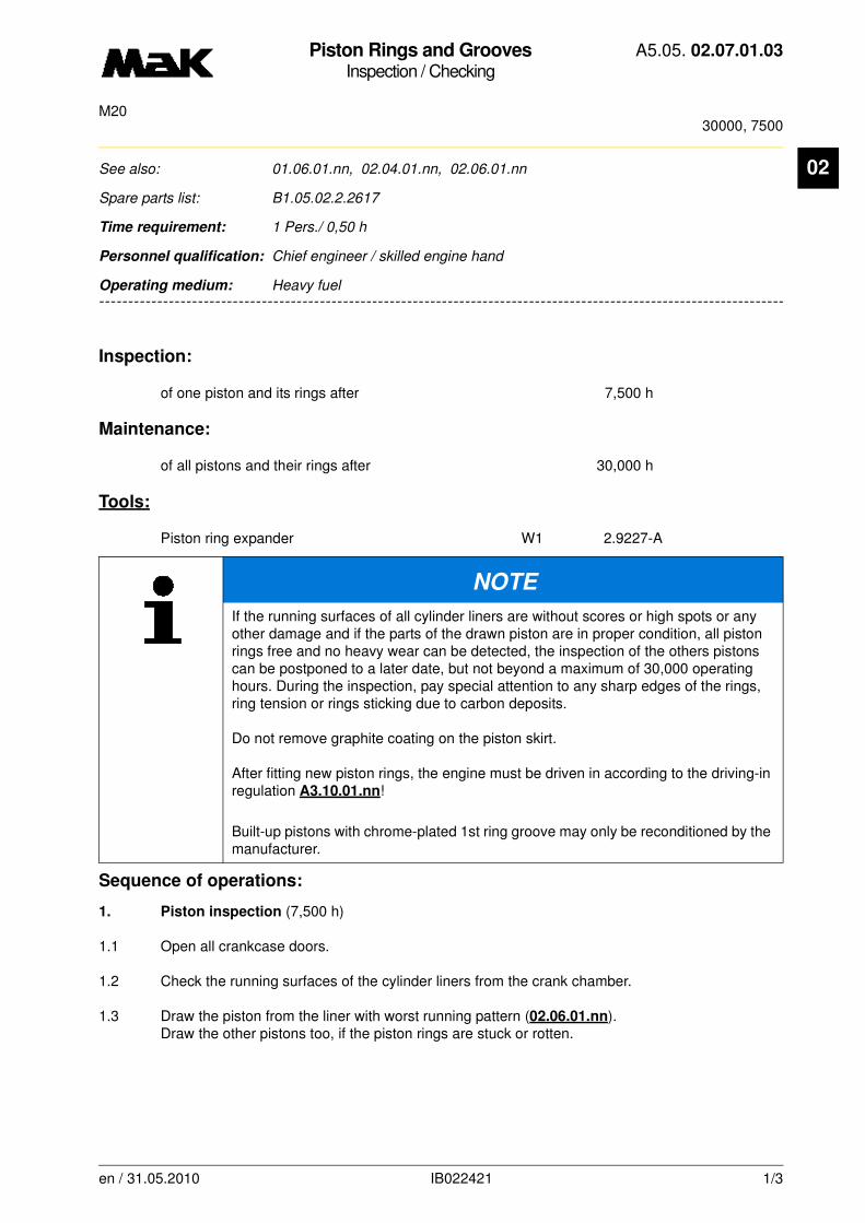
Piston Rings and GroovesInspection / Checking
A5.05. 02.07.01.03
30000, 7500M20
02
-------
See also: 01.06.01.nn, 02.04.01.nn, 02.06.01.nn
Spare parts list: B1.05.02.2.2617
Time requirement: 1 Pers./ 0,50 h
Personnel qualification: Chief engineer / skilled engine hand
-------------------------------------------------------------------------------------------------------------------------
Operating medium: Heavy fuel
Inspection:
of one piston and its rings after 7,500 h
Maintenance:
of all pistons and their rings after 30,000 h
Tools:
Piston ring expander W1 2.9227-A
Sequence of operations:
1. Piston inspection (7,500 h)
1.1 Open all crankcase doors.
1.2 Check the running surfaces of the cylinder liners from the crank chamber.
1.3 Draw the piston from the liner with worst running pattern (02.06.01.nn). Draw the other pistons too, if the piston rings are stuck or rotten.
NOTE
If the running surfaces of all cylinder liners are without scores or high spots or any other damage and if the parts of the drawn piston are in proper condition, all piston rings free and no heavy wear can be detected, the inspection of the others pistons can be postponed to a later date, but not beyond a maximum of 30,000 operating hours. During the inspection, pay special attention to any sharp edges of the rings, ring tension or rings sticking due to carbon deposits.
Do not remove graphite coating on the piston skirt.
After fitting new piston rings, the engine must be driven in according to the driving-in regulation A3.10.01.nn!
Built-up pistons with chrome-plated 1st ring groove may only be reconditioned by the manufacturer.
en / 31.05.2010 IB022421 1/3
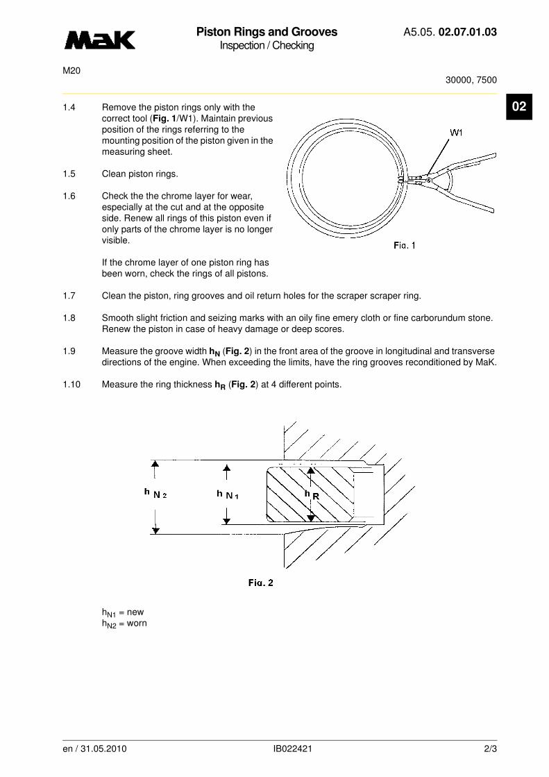
Piston Rings and GroovesInspection / Checking
A5.05. 02.07.01.03
30000, 7500M20
02
1.4 Remove the piston rings only with the correct tool (Fig. 1/W1). Maintain previous position of the rings referring to the mounting position of the piston given in the measuring sheet.1.5 Clean piston rings.
1.6 Check the the chrome layer for wear, especially at the cut and at the opposite side. Renew all rings of this piston even if only parts of the chrome layer is no longer visible.
If the chrome layer of one piston ring has been worn, check the rings of all pistons.
1.7 Clean the piston, ring grooves and oil return holes for the scraper scraper ring.
1.8 Smooth slight friction and seizing marks with an oily fine emery cloth or fine carborundum stone. Renew the piston in case of heavy damage or deep scores.
1.9 Measure the groove width hN (Fig. 2) in the front area of the groove in longitudinal and transverse directions of the engine. When exceeding the limits, have the ring grooves reconditioned by MaK.
1.10 Measure the ring thickness hR (Fig. 2) at 4 different points.
hN1 = newhN2 = worn
en / 31.05.2010 IB022421 2/3

Piston Rings and GroovesInspection / Checking
A5.05. 02.07.01.03
30000, 7500M20
02
1.11 Determine the clearance by calculation and check it against the table.Ring thicknes hR Groove width hN Limit of hN - hRGroove Nominal Wear limit mm
mm mm
1 – 2 4.95 5.6 0.65
3 6 6.5 0.5
1.12 Fit piston rings with the marking facing upwards (Fig. 3/X) and with the ring stops into the ring grooves alternatingly opposite in engine longitudinal direction.
2. Maintenance (30,000 h)
2.1 Draw all pistons (02.06.01.nn).
2.2 Check the state of lubrication and appearance of the running surface of the piston and clean it.
2.3 Remove the piston rings with piston ring expander (Fig. 1/W1). Maintain previous position of the rings referring to the mounting position of the piston given in the measuring sheet.
2.4 Clean all ring grooves.
2.5 Measure the groove width hN in accordance with sequence of operations 1.9.
2.6 Renew all compression and scraper rings.
2.6.1 Fit piston rings with the marking facing
upwards (Fig. 3/X) and with the ring
stops into the ring grooves
alternatingly opposite in engine
longitudinal direction.
2.7 Fit all pistons (02.06.02.nn).
en / 31.05.2010 IB022421 3/3

PistonMaintenance / Reassembly
A5.05. 02.10.01.01
M20
02
-------
See also: 02.04.02.nn, 02.07.01.nn
Spare parts list: B1.05.02.2.2601
Time requirement: 1 Pers./ 0,50 h
Personnel qualification: skilled engine hand
-------------------------------------------------------------------------------------------------------------------------
Operating medium: Heavy fuel and distillate fuel
Tools:
Mounting/extraction device for pistons W1 1.9080-012Cylinder liner holder W2 2.9217 APiston assembly ring W3 2.9220 BPiston insertion device (sheet metal sleeve) W4 259220 A
Auxiliary material:
Molykote paste "G-Rapid Plus“ **
** or a product of equal standard
Sequence of operations:
1. Replace the piston rings as required.
2. Fit the new piston rings with the ring joints in a longitudinal direction to the engine alternately arranged opposite each other! Lubricate the piston rings and pistons well on the outside.
NOTE
The cylinder liner must always be secured by means of the cylinder liner holder (fig.
3/W2) to prevent the cylinder liner from coming loose when turning the engine (wit-hout dismantled cylinder head)!
Pay attention to the cylinder number mark on the bottom end.
Drive in the engine according to the driving-in regulation (A3.10.01.nn) after fitting a new piston/new piston rings!
en / 30.09.2010 IB004785 1/3
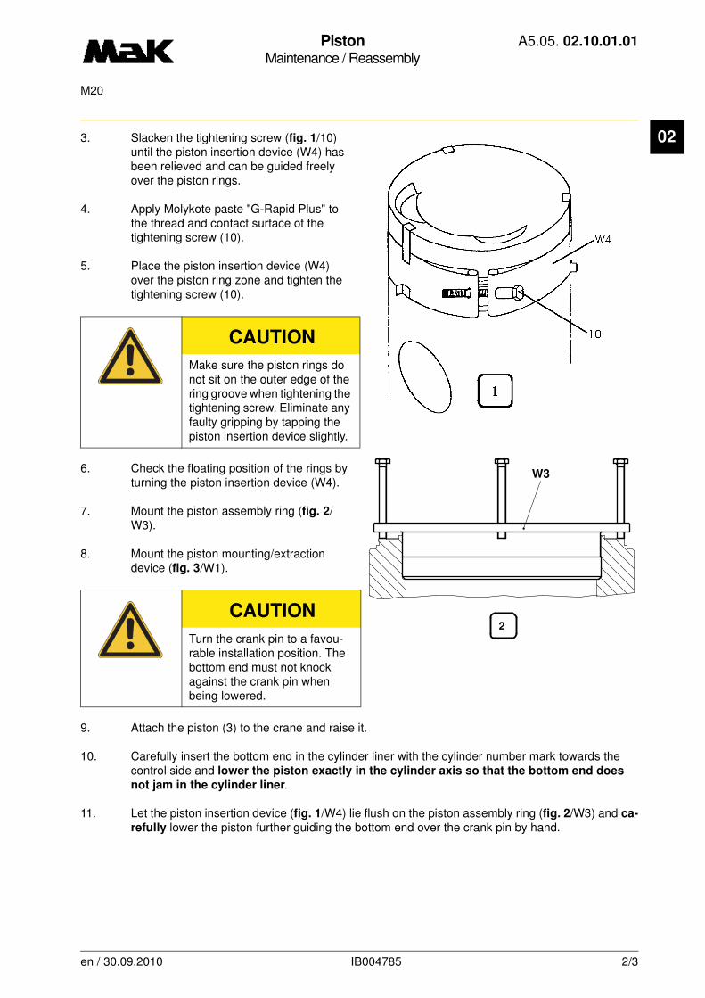
PistonMaintenance / Reassembly
A5.05. 02.10.01.01
M20
02
3. Slacken the tightening screw (fig. 1/10) until the piston insertion device (W4) has been relieved and can be guided freely over the piston rings.4. Apply Molykote paste "G-Rapid Plus" to the thread and contact surface of the tightening screw (10).
5. Place the piston insertion device (W4) over the piston ring zone and tighten the tightening screw (10).
6. Check the floating position of the rings by turning the piston insertion device (W4).
7. Mount the piston assembly ring (fig. 2/W3).
8. Mount the piston mounting/extraction device (fig. 3/W1).
9. Attach the piston (3) to the crane and raise it.
10. Carefully insert the bottom end in the cylinder liner with the cylinder number mark towards the control side and lower the piston exactly in the cylinder axis so that the bottom end does
not jam in the cylinder liner.
11. Let the piston insertion device (fig. 1/W4) lie flush on the piston assembly ring (fig. 2/W3) and ca-
refully lower the piston further guiding the bottom end over the crank pin by hand.
CAUTION
Make sure the piston rings do not sit on the outer edge of the ring groove when tightening the tightening screw. Eliminate any faulty gripping by tapping the piston insertion device slightly.
CAUTION
Turn the crank pin to a favou-rable installation position. The bottom end must not knock against the crank pin when being lowered.
2
W3
en / 30.09.2010 IB004785 2/3
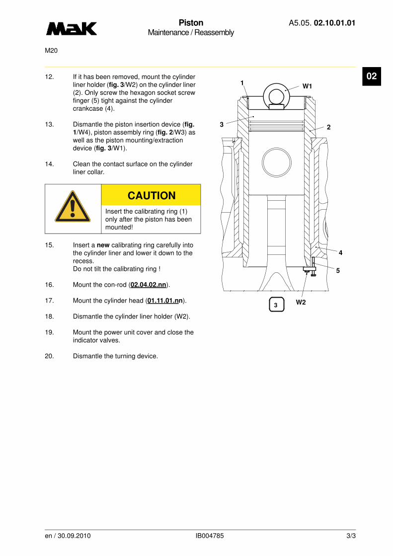
PistonMaintenance / Reassembly
A5.05. 02.10.01.01
M20
02
12. If it has been removed, mount the cylinder liner holder (fig. 3/W2) on the cylinder liner (2). Only screw the hexagon socket screw finger (5) tight against the cylinder crankcase (4).13. Dismantle the piston insertion device (fig.
1/W4), piston assembly ring (fig. 2/W3) as well as the piston mounting/extraction device (fig. 3/W1).
14. Clean the contact surface on the cylinder liner collar.
15. Insert a new calibrating ring carefully into the cylinder liner and lower it down to the recess.Do not tilt the calibrating ring !
16. Mount the con-rod (02.04.02.nn).
17. Mount the cylinder head (01.11.01.nn).
18. Dismantle the cylinder liner holder (W2).
19. Mount the power unit cover and close the indicator valves.
20. Dismantle the turning device.
CAUTION
Insert the calibrating ring (1) only after the piston has been mounted!
23
1
4
5
W2
W1
3
en / 30.09.2010 IB004785 3/3
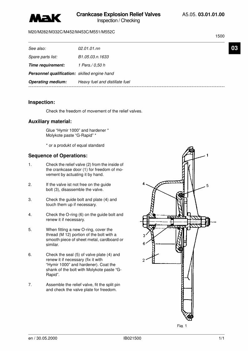
Crankcase Explosion Relief ValvesInspection / Checking
A5.05. 03.01.01.00
1500M20/M282/M332C/M452/M453C/M551/M552C
en / 30.05.2000 IB021500 1/1
03See also: 02.01.01.nn
Spare parts list: B1.05.03.n.1633
Time requirement: 1 Pers./ 0,50 h
Personnel qualification: skilled engine hand
--------------------------------------------------------------------------------------------------------------------------------
Operating medium: Heavy fuel and distillate fuel
Inspection:
Check the freedom of movement of the relief valves.
Auxiliary material:
Glue “Hymir 1000” and hardener *Molykote paste “G-Rapid” *
* or a produkt of equal standard
Sequence of Operations:
1. Check the relief valve (2) from the inside of the crankcase door (1) for freedom of mo-vement by actuating it by hand.
2. If the valve ist not free on the guide bolt (3), disassemble the valve.
3. Check the guide bolt and plate (4) and touch them up if necessary.
4. Check the O-ring (6) on the guide bolt and renew it if necessary.
5. When fitting a new O-ring, cover the thread (M 12) portion of the bolt with a smooth piece of sheet metal, cardboard or similar.
6. Check the seal (5) of valve plate (4) and renew it if necessary (fix it with “Hymir 1000” and hardener). Coat the shank of the bolt with Molykote paste “G-Rapid”.
7. Assemble the relief valve, fit the split pin and check the valve plate for freedom.
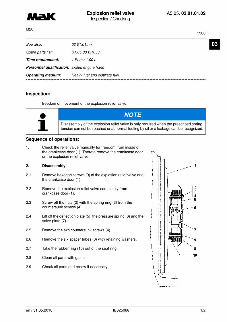
Explosion relief valveInspection / Checking
A5.05. 03.01.01.02
1500M20
03
-------
See also: 02.01.01.nn
Spare parts list: B1.05.03.2.1633
Time requirement: 1 Pers./ 1,00 h
Personnel qualification: skilled engine hand
-------------------------------------------------------------------------------------------------------------------------
Operating medium: Heavy fuel and distillate fuel
Inspection:
freedom of movement of the explosion relief valve.
Sequence of operations:
1. Check the relief valve manually for freedom from inside of the crankcase door (1). Thereto remove the crankcase door or the explosion relief valve.
2. Disassembly
2.1 Remove hexagon screws (9) of the explosion relief valve and the crankcase door (1).
2.2 Remove the explosion relief valve completely from crankcase door (1).
2.3 Screw off the nuts (2) with the spring ring (3) from the countersunk screws (4).
2.4 Lift off the deflection plate (5), the pressure spring (6) and the valve plate (7).
2.5 Remove the two countersunk screws (4).
2.6 Remove the six spacer tubes (8) with retaining washers.
2.7 Take the rubber ring (10) out of the seat ring.
2.8 Clean all parts with gas oil.
2.9 Check all parts and renew if necessary.
NOTE
Disassembly of the explosion relief valve is only required when the prescribed spring tension can not be reached or abnormal fouling by oil or a leakage can be recognized.
en / 31.05.2010 IB025068 1/2

Explosion relief valveInspection / Checking
A5.05. 03.01.01.02
1500M20
03
3. Reassembly3.1 Reassembly is done in reverse order of disassembly.
3.2 Tighten connecting bolts (9) using a torque of
M = 24,5 Nm
3.3 Check the explosion relief valve for proper function by manual operation after assembly.
3.4 When mounting the explosion relief valve to the crankcase door be sure that the sealing between seat ring and crankcase door is in proper condition.
en / 31.05.2010 IB025068 2/2

Explosion relief valveInspection / Checking
A5.05. 03.01.01.03
1500M20
03
-------
See also: 02.01.01.nn
Spare parts list: B1.05.03.2.1633
Time requirement: 1 Pers./ 1,00 h
Personnel qualification: skilled engine hand
-------------------------------------------------------------------------------------------------------------------------
Operating medium: Heavy fuel and distillate fuel
Check:
Ease of movement of the explosion relief valve every 1,500 h
Auxiliary materials:
Molykote Paste "G Rapid Plus“ *
Sealing compound "Dirko No. 610.020" *
* or equivalent product
Procedure:
1. Check the relief valve from the inside of the crankcase door (1) for ease of movement by actua-ting the valve by hand. For this purpose dismantle the crankcase door (1) or the explosion relief valve (5).
2. Disassembly
2.1 Unscrew and remove screws (8) from crankcase door (1).
2.2 Remove explosion relief valve (5) from the crankcase cover (1).
3. Assembly
3.1 Coat the threads of screws (8) slightly with Molykote Paste "G-Rapid Plus".
3.2 Clean the sealing face (10) on the crankcase door (1) and lubricate with sealing compound "Dirko No. 610.020".
3.3 Put the explosion relief valve (5) in place on the crankcase door (1).
NOTE
Removal of the explosion relief valve (5) is only required if the specified spring tension is not provided any more, in the event of abnormal oil contamination or if any leaks should be identified during operation.
en / 30.09.2010 IB026533 1/2
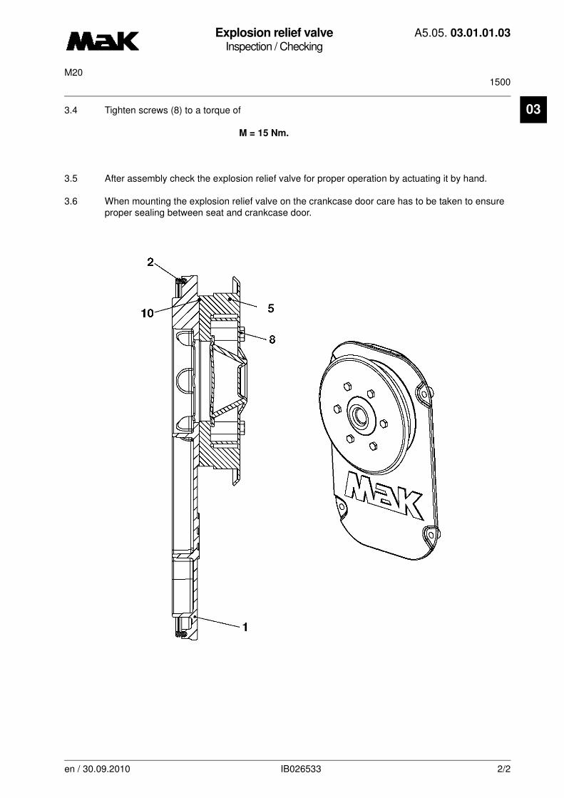
Explosion relief valveInspection / Checking
A5.05. 03.01.01.03
1500M20
03
3.4 Tighten screws (8) to a torque ofM = 15 Nm.
3.5 After assembly check the explosion relief valve for proper operation by actuating it by hand.
3.6 When mounting the explosion relief valve on the crankcase door care has to be taken to ensure proper sealing between seat and crankcase door.
en / 30.09.2010 IB026533 2/2
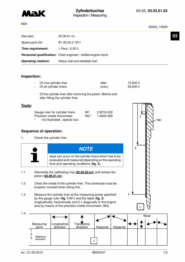
ZylinderbuchseInspection / Measuring
A5.05. 03.03.01.02
30000, 15000M20
03
-------
See also: 02.06.01.nn
Spare parts list: B1.05.03.2.1611
Time requirement: 1 Pers./ 0,50 h
Personnel qualification: Chief engineer / skilled engine hand
-------------------------------------------------------------------------------------------------------------------------
Operating medium: Heavy fuel and distillate fuel
Inspection:
- Of one cylinder liner after 15,000 h- Of all cylinder liners every 30,000 h
- Of the cylinder liner after removing the piston. Before and after fitting the cylinder liner.
Tools:
Gauge ruler for cylinder liners W1 2.9216-022Precision inside micrometer W2 * 1.9425-300* not illustrated , special tool
Sequence of operation:
1. Check the cylinder liner.
1.1 Dismantle the calibrating ring (02.05.50.nn) and extract the piston (02.06.01.nn).
1.2 Clean the inside of the cylinder liner. The crankcase must be properly covered when doing this.
1.3 Measure the cylinder liner at the measuring points specified by the gauge ruler (fig. 1/W1) and the table (fig. 2) longitudinally, transversally and 2 x diagonally to the engine axis by means of the precision inside micrometer (W2).
1.4
NOTE
wear can occur on the cylinder liners which has to be evaluated and measured depending on the operating time and operating conditions (fig. 3).
Wear
Measuring Longitudinal Transverse point direction direction Diagonal Diagonal
Reference dimension
123
en / 31.05.2010 IB022447 1/2

ZylinderbuchseInspection / Measuring
A5.05. 03.03.01.02
30000, 15000M20
03
1.5 Enter the measured values in the table (fig. 2) and then determine the wear (d1 - reference dimension d3 etc.). Also refer to the measuring sheet in the "forms for maintenance reports" folder”.1.6 When the wear limit, normally in the area of the upper piston ring point of return (fig.
3/4; TDC, first ring) or other limit values indicate in the table are reached, then the cylinder liner must be replaced.Reconditioning of the cylinder liners is only possible by Caterpillar / MaK.
Cylinder liner wear chart
Evaluation criteria Wear limit Explanation(mm)
Nominal Ø (new) * Radius r ≥ 3mm
200 +46 ** in circumferencial direction*** 1: Gusset, 2: Pocket, 3: Scores
Wear 0,8 4: TDC 1st. ring, 5: Canyon
Max. out-or-round 0,25
Gusset Height 6,00 wedge-shaped indentation across theDepth * 0,03 entire circumference, beginning from
the TDC of 1st. piston ring.
Canyon max. number 3 Individual deep blow-through ductsHeight 6,00 in the area of the first piston ring total width 3,00 (TDC).
Scores Number 3 Vertical and linear scores.Height 140,00Depth 0,03
Pocket Number 3 Irregular indentations.Height 45,00Width ** 15,00Depth * 0,02
en / 31.05.2010 IB022447 2/2
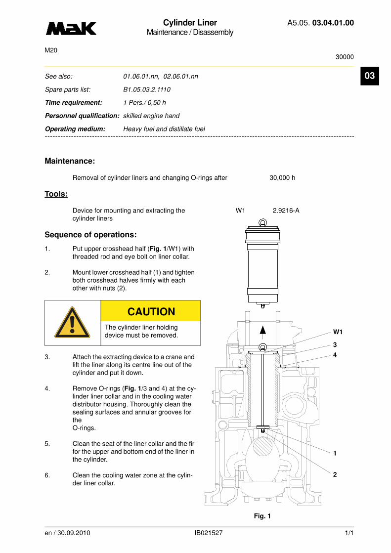
Cylinder LinerMaintenance / Disassembly
A5.05. 03.04.01.00
30000M20
en / 30.09.2010 IB021527 1/1
03See also: 01.06.01.nn, 02.06.01.nn
Spare parts list: B1.05.03.2.1110
Time requirement: 1 Pers./ 0,50 h
Personnel qualification: skilled engine hand
--------------------------------------------------------------------------------------------------------------------------------
Operating medium: Heavy fuel and distillate fuel
Maintenance:
Removal of cylinder liners and changing O-rings after 30,000 h
Tools:
Device for mounting and extracting the W1 2.9216-Acylinder liners
Sequence of operations:
1. Put upper crosshead half (Fig. 1/W1) with threaded rod and eye bolt on liner collar.
2. Mount lower crosshead half (1) and tighten both crosshead halves firmly with each other with nuts (2).
3. Attach the extracting device to a crane and lift the liner along its centre line out of the cylinder and put it down.
4. Remove O-rings (Fig. 1/3 and 4) at the cy-linder liner collar and in the cooling water distributor housing. Thoroughly clean the sealing surfaces and annular grooves for the O-rings.
5. Clean the seat of the liner collar and the fir for the upper and bottom end of the liner in the cylinder.
6. Clean the cooling water zone at the cylin-der liner collar.
CAUTION
The cylinder liner holding device must be removed.
W1
3
4
1
2
Fig. 1
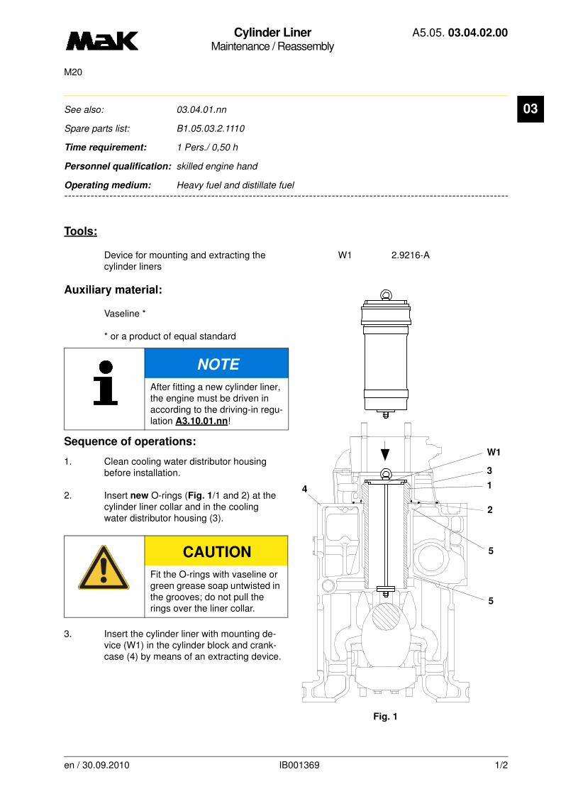
Cylinder LinerMaintenance / Reassembly
A5.05. 03.04.02.00
M20
03
-------
See also: 03.04.01.nn
Spare parts list: B1.05.03.2.1110
Time requirement: 1 Pers./ 0,50 h
Personnel qualification: skilled engine hand
-------------------------------------------------------------------------------------------------------------------------
Operating medium: Heavy fuel and distillate fuel
Tools:
Device for mounting and extracting the W1 2.9216-Acylinder liners
Auxiliary material:
Vaseline *
* or a product of equal standard
Sequence of operations:
1. Clean cooling water distributor housing before installation.
2. Insert new O-rings (Fig. 1/1 and 2) at the cylinder liner collar and in the cooling water distributor housing (3).
3. Insert the cylinder liner with mounting de-vice (W1) in the cylinder block and crank-case (4) by means of an extracting device.
NOTE
After fitting a new cylinder liner, the engine must be driven in according to the driving-in regu-lation A3.10.01.nn!
CAUTION
Fit the O-rings with vaseline or green grease soap untwisted in the grooves; do not pull the rings over the liner collar.
W1
3
1
Fig. 1
2
5
5
4
en / 30.09.2010 IB001369 1/2
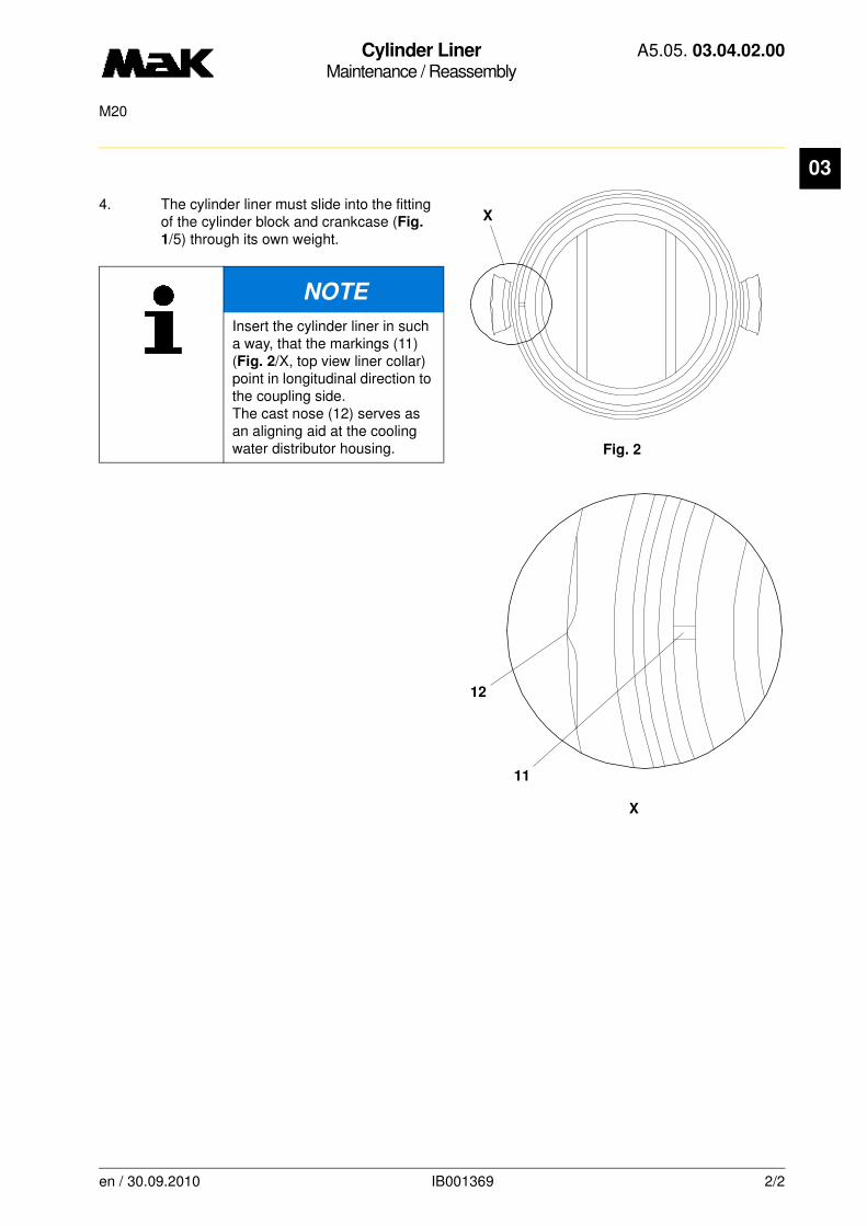
Cylinder LinerMaintenance / Reassembly
A5.05. 03.04.02.00
M20
03
4. The cylinder liner must slide into the fitting of the cylinder block and crankcase (Fig.
1/5) through its own weight.
NOTE
Insert the cylinder liner in such a way, that the markings (11) (Fig. 2/X, top view liner collar) point in longitudinal direction to the coupling side. The cast nose (12) serves as an aligning aid at the cooling water distributor housing. Fig. 2
X
X
12
11
en / 30.09.2010 IB001369 2/2
Engine Bolting and UnionsInspection / Checking
A5.05. 03.07.01.00
150M20
en / 10.08.2010 IB001402 1/1
03See also: 02.02.01.nn
Spare parts list: B1.05.06.2.7210, B1.05.07.2.8510
Time requirement: 1 Pers./ 2,00 h
Personnel qualification: skilled engine hand
--------------------------------------------------------------------------------------------------------------------------------
Operating medium: Heavy fuel and distillate fuel
Inspection:
of all bolts, unions and screwed connections for good fitting and leaks.
Sequence of operations:
1. Check the flanged connections, filter thermostats and pipe clamps of the followinf systems for good mounting and leaks:
• Cooling water
• Lubricating oil
• Fuel
• Exhaust gas
• Starting air
• Pneumatic control
2. Retighten the fixing bolts of the brackets for the injection pump control rod and check the locking washers and pins of the linkage.
3. Check the monitoring and control equipment for good fitting. Cables and signal lines must not scrape against any part.
4. Check the foundation bolts by knocking. Measure the crank web deflection after tightening slack foundation bolts (02.02.01.nn).
Consult MaK aftersales service for tightening values.
5. Check the elastic bearing elements for damages.
NOTE
This precautionary measure has to be taken once to detect any leaks and/or slack screwed connections that might result from some parts or gaskets taking a set that could cause damage.
When starting up a new plant (150 h) and/or after major repairs, the engine unions and screwed connections have to be inspected for good fitting and leaks.

Camshaft BearingInspection / Checking
A5.05. 04.01.01.00
30000, 15000M20
en / 30.09.2010 IB026569 1/1
04See also: 02.01.01.nn, 04.01.02.nn
Spare parts list: B1.05.04.2.3120
Time requirement: 1 Pers./ 0,20 h
Personnel qualification: skilled engine hand
--------------------------------------------------------------------------------------------------------------------------------
Operating medium: Heavy fuel and distillate fuel
Inspection:
- Bearing clearance of one camshaft bearing after 15,000 h
- Bearing clearance of all camshaft bearings after 30,000 h
Sequence of operations:
1. Check the camshaft bearing clearance.
1.1 Open corresponding inspection glass lid of the camshaft door on the control side.
1.2 Measure clearance camshaft bearing / bearing neck.
New clearance Clearance limitmm mm
0,11 - 0,165 0,22
NOTE
Camshaft bearings are not subjected to load changes. The load on the bearing occurs exceptionally in the lower contact area and is relatively heavy in this area. Smooth overload along the edges is not unusual.
NOTE
With reaching the clearance limit the camshaft bearing is to be replaced (MaK customer support) and the clearance of all camshaft bearings are to be checked. Check running surface of the bearing necks of the corresponding camshaft bearings.

CamshaftRepair / Disassembly and reassembly
A5.05. 04.04.01.00
M20
04
-------
See also: 01.01.01.nn, 01.02.01.nn
Spare parts list: B1.05.04.2.3120
Time requirement: 2 Pers./ 2,00 h
Personnel qualification: skilled engine hand
-------------------------------------------------------------------------------------------------------------------------
Operating medium: Heavy fuel and distillate fuel
Tools:
Camshaft - mounting device W1 2.9230-ALocking screw W2Torque wrench 40 - 180 Nm W3 1.9454-40Hexagon socket wrench 10 mm W4 * 1.9039-10Turning rod W5 * 2.9100-380
* not available as figure
Auxiliary material:
Sliding coating Metaflux ** Molykote paste ”G-Rapid Plus” **
** or a product of equal standard
Sequence of operations:
1. Disassembly
1.1 Open the decompression valves.
1.2 Remove the camshaft cover at the camshaft side and the cover on the opposite side of the clutch.
1.3 Remove the valve rocker of this cylinder and all cylinders to the right of it (01.02.01.nn).
1.4 Lift the rockers of the corresponding inlet and exhaust valve drives (Fig. 1/1) from the cams and secure with locking screw (W2).
Fig. 1
W2
1
en / 31.05.2010 IB001455 1/3
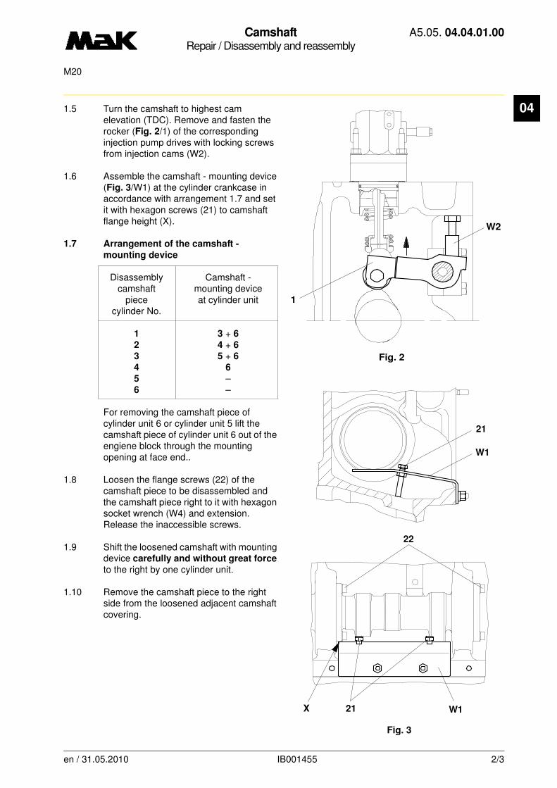
CamshaftRepair / Disassembly and reassembly
A5.05. 04.04.01.00
M20
04
1.5 Turn the camshaft to highest cam elevation (TDC). Remove and fasten the rocker (Fig. 2/1) of the corresponding injection pump drives with locking screws from injection cams (W2).1.6 Assemble the camshaft - mounting device (Fig. 3/W1) at the cylinder crankcase in accordance with arrangement 1.7 and set it with hexagon screws (21) to camshaft flange height (X).
1.7 Arrangement of the camshaft -
mounting device
Disassembly Camshaft -camshaft mounting device
piece at cylinder unitcylinder No.
1 3 + 62 4 + 63 5 + 64 6
5 –6 –
For removing the camshaft piece of cylinder unit 6 or cylinder unit 5 lift the camshaft piece of cylinder unit 6 out of the engiene block through the mounting opening at face end..
1.8 Loosen the flange screws (22) of the camshaft piece to be disassembled and the camshaft piece right to it with hexagon socket wrench (W4) and extension. Release the inaccessible screws.
1.9 Shift the loosened camshaft with mounting device carefully and without great force to the right by one cylinder unit.
1.10 Remove the camshaft piece to the right side from the loosened adjacent camshaft covering.
Fig. 2
W2
1
Fig. 3
21
W1
22
21 W1X
en / 31.05.2010 IB001455 2/3

CamshaftRepair / Disassembly and reassembly
A5.05. 04.04.01.00
M20
04
2. Assembly
Camshaft Flangepiece index
cylinder No.
1 4
2 2
3 3
4 4
5 5
6 6
2.1 Position the camshaft pieces in reverse disassembly order.
2.2 Grease the threads and contact surfaces of the flange screws with Molykote paste ”G-Rapid Plus” and bolt the loosened camshaft pieces.
2.3 Tighten the flange screws crosswise with a torque of
100 Nm = 50°°°° angle of rotation.
Remove the camshaft - mounting devices (W1).
2.4 Remove the locking screws (W2) of the raised valve and pump drive rocker.
2.5 Mount the valve rocker (01.02.01.nn) and check the valve clearance (01.01.01.nn).
2.6 Check the lubricating oil flow.
CAUTION
Do not cant camshaft piece in the camshaft bearings during removal. Handle with utmost caution. Danger of destruction of the bearings.
NOTE
The camshaft flange (Fig. 4/31) of every piece is pinned according to the cylinder and position in accordance with the firing order (32) and provided with a flange index (33) (see table).
Fig. 433
32
31
en / 31.05.2010 IB001455 3/3

CamshaftRepair / Disassembly and reassembly
A5.05. 04.04.01.01
M20
04
-------
See also: 01.01.01.nn, 01.02.01.nn
Spare parts list: B1.05.04.2.3120
Time requirement: 2 Pers./ 2,00 h
Personnel qualification: skilled engine hand
-------------------------------------------------------------------------------------------------------------------------
Operating medium: Heavy fuel and distillate fuel
Tools:
Camshaft - mounting device W1 2.9230-ALocking screw W2Torque wrench 40 - 180 Nm W3 1.9454-40Hexagon socket wrench 10 mm W4 * 1.9039-10Turning rod W5 * 2.9100-380
* not available as figure
Auxiliary material:
Sliding coating Metaflux ** Molykote paste ”G-Rapid Plus” **
** or a product of equal standard
Sequence of operations:
1. Disassembly
1.1 Open the decompression valves.
1.2 Remove the camshaft cover at the camshaft side and the cover on the opposite side of the clutch.
1.3 Remove the valve rocker of this cylinder and all cylinders to the right of it (01.02.01.nn).
1.4 Lift the rockers of the corresponding inlet and exhaust valve drives (Fig. 1/1) from the cams and secure with locking screw (W2).
Fig. 1
W2
1
en / 30.09.2010 IB002113 1/3

CamshaftRepair / Disassembly and reassembly
A5.05. 04.04.01.01
M20
04
1.5 Turn the camshaft to highest cam elevation (TDC). Remove and fasten the rocker (Fig. 2/1) of the corresponding injection pump drives with locking screws from injection cams (W2).1.6 Assemble the camshaft - mounting device (Fig. 3/W1) at the cylinder crankcase in accordance with arrangement 1.7 and set it with hexagon screws (21) to camshaft flange height (X).
1.7 Arrangement of the camshaft - mounting device
Disassembly Camshaft -camshaft mounting device
piece at cylinder unitcylinder No.
1 3 + 72 4 + 83 5 + 84 6 + 9
5 7 + 9
6 8
7 9
8 –
9 –
For removing the camshaft piece of cylinder unit 9 or cylinder unit 8 lift the camshaft piece of cylinder unit 9 out of the engiene block through the mounting opening at face end.
1.8 Loosen the flange screws (22) of the camshaft piece to be disassembled and the camshaft piece right to it with hexagon socket wrench (W4) and extension. Release the inaccessible screws.
1.9 Shift the loosened camshaft with mounting device carefully and without great force to the right by one cylinder unit.
1.10 Remove the camshaft piece to the right side from the loosened adjacent camshaft covering.
Fig. 2
W2
1
Fig. 3
21
W1
22
21 W1X
en / 30.09.2010 IB002113 2/3
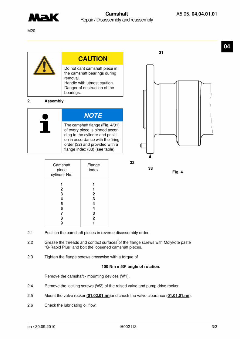
CamshaftRepair / Disassembly and reassembly
A5.05. 04.04.01.01
M20
04
2. Assembly
Camshaft Flangepiece index
cylinder No.
1 1
2 1
3 2
4 3
5 4
6 4
7 3
8 2
9 1
2.1 Position the camshaft pieces in reverse disassembly order.
2.2 Grease the threads and contact surfaces of the flange screws with Molykote paste ”G-Rapid Plus” and bolt the loosened camshaft pieces.
2.3 Tighten the flange screws crosswise with a torque of
100 Nm = 50°°°° angle of rotation.
Remove the camshaft - mounting devices (W1).
2.4 Remove the locking screws (W2) of the raised valve and pump drive rocker.
2.5 Mount the valve rocker (01.02.01.nn)and check the valve clearance (01.01.01.nn).
2.6 Check the lubricating oil flow.
CAUTION
Do not cant camshaft piece in the camshaft bearings during removal. Handle with utmost caution. Danger of destruction of the bearings.
NOTE
The camshaft flange (Fig. 4/31) of every piece is pinned accor-ding to the cylinder and positi-on in accordance with the firing order (32) and provided with a flange index (33) (see table).
Fig. 433
32
31
en / 30.09.2010 IB002113 3/3
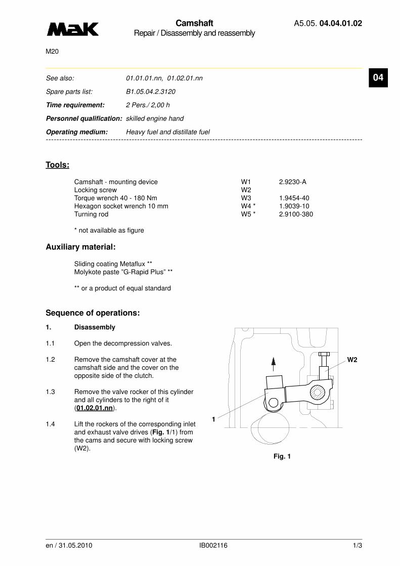
CamshaftRepair / Disassembly and reassembly
A5.05. 04.04.01.02
M20
04
-------
See also: 01.01.01.nn, 01.02.01.nn
Spare parts list: B1.05.04.2.3120
Time requirement: 2 Pers./ 2,00 h
Personnel qualification: skilled engine hand
-------------------------------------------------------------------------------------------------------------------------
Operating medium: Heavy fuel and distillate fuel
Tools:
Camshaft - mounting device W1 2.9230-ALocking screw W2Torque wrench 40 - 180 Nm W3 1.9454-40Hexagon socket wrench 10 mm W4 * 1.9039-10Turning rod W5 * 2.9100-380
* not available as figure
Auxiliary material:
Sliding coating Metaflux ** Molykote paste ”G-Rapid Plus” **
** or a product of equal standard
Sequence of operations:
1. Disassembly
1.1 Open the decompression valves.
1.2 Remove the camshaft cover at the camshaft side and the cover on the opposite side of the clutch.
1.3 Remove the valve rocker of this cylinder and all cylinders to the right of it (01.02.01.nn).
1.4 Lift the rockers of the corresponding inlet and exhaust valve drives (Fig. 1/1) from the cams and secure with locking screw (W2).
Fig. 1
W2
1
en / 31.05.2010 IB002116 1/3

CamshaftRepair / Disassembly and reassembly
A5.05. 04.04.01.02
M20
04
1.5 Turn the camshaft to highest cam elevation (TDC). Remove and fasten the rocker (Fig. 2/1) of the corresponding injection pump drives with locking screws from injection cams (W2).1.6 Assemble the camshaft - mounting device (Fig. 3/W1) at the cylinder crankcase in accordance with arrangement 1.7 and set it with hexagon screws (21) to camshaft flange height (X).
1.7 Arrangement of the camshaft -
mounting device
Disassembly Camshaft -camshaft mounting device
piece at cylinder unitcylinder No.
1 3 + 72 4 + 73 5 + 84 6 + 8
5 7 + 8
6 8
7 –
8 –
For removing the camshaft piece of cylinder unit 8 or cylinder unit 7 lift the camshaft piece of cylinder unit 8 out of the engiene block through the mounting opening at face end.
1.8 Loosen the flange screws (22) of the camshaft piece to be disassembled and the camshaft piece right to it with hexagon socket wrench (W4) and extension. Release the inaccessible screws.
1.9 Shift the loosened camshaft with mounting device carefully and without great force to the right by one cylinder unit.
1.10 Remove the camshaft piece to the right side from the loosened adjacent camshaft covering.
Fig. 2
W2
1
Fig. 3
21
W1
22
21 W1X
en / 31.05.2010 IB002116 2/3

CamshaftRepair / Disassembly and reassembly
A5.05. 04.04.01.02
M20
04
2. Assembly
Camshaft Flangepiece index
cylinder No.
1 5
2 2
3 3
4 4
5 5
6 6
7 7
8 8
2.1 Position the camshaft pieces in reverse disassembly order.
2.2 Grease the threads and contact surfaces of the flange screws with Molykote paste ”G-Rapid Plus” and bolt the loosened camshaft pieces.
2.3 Tighten the flange screws crosswise with a torque of
100 Nm = 50°°°° angle of rotation.
Remove the camshaft - mounting devices (W1).
2.4 Remove the locking screws (W2) of the raised valve and pump drive rocker.
2.5 Mount the valve rocker (01.02.01.nn) and check the valve clearance (01.01.01.nn).
2.6 Check the lubricating oil flow.
CAUTION
Do not cant camshaft piece in the camshaft bearings during removal. Handle with utmost caution. Danger of destruction of the bearings.
NOTE
The camshaft flange (Fig. 4/31) of every piece is pinned accor-ding to the cylinder and positi-on in accordance with the firing order (32) and provided with a flange index (33) (see table).
Fig. 433
32
31
en / 31.05.2010 IB002116 3/3

Timing Gear TrainInspection / Checking
A5.05. 04.08.01.00
3750M20
en / 30.09.2010 IB022002 1/1
04See also:
Spare parts list: B1.05.04.2.5140
Time requirement: 1 Pers./ 0,50 h
Personnel qualification: skilled engine hand
--------------------------------------------------------------------------------------------------------------------------------
Operating medium: Heavy fuel and distillate fuel
Inspection:
Working surfaces of the teeth 3,750 h
Sequence of operation:
1. Remove the covers at the gear housing on the camshaft and exhaust side.
1.1 Check the tooth surfaces of the camshaft gear (Fig. 1/1), intermediate wheel (2) and crankshaft gear (3) (pitting, cross bearing, disintegrations etc.)
1.2 Check the function of the oil nozzles (4, 5 and 6).
1.3 Fit the covers and check the gaskets.
2. Replace the O-rings on the intermediate wheel axle (7).
2.1 Remove locking plate (Fig. 2/10).
2.2 Shift the intermediate wheel axle (7) from the gear housing in the direction of the coupling side and renew the O-ring (11).
CAUTION
The preset tooth meshing of the intermediate wheel to the cams-haft gear and crankshaft gear must not be adjusted. Danger of timing adjustment!
Fig. 1
1
7
6
4
2
5
3
10
11 7
Fig. 2

Governor DriveInspection / Disassembly and reassembly
A5.05. 04.08.03.00
15000M20
04
-------
See also:
Spare parts list: B1.05.04.2.4111
Time requirement: 1 Pers./ 2,00 h
Personnel qualification: skilled engine hand
-------------------------------------------------------------------------------------------------------------------------
Operating medium: Heavy fuel and distillate fuel
Inspection:
Contact reflection at helical gear wheels every 15,000 h
Tools:
Torque wrench 40 - 180 Nm 1/2" W1 * 1.9454-40
* not available as figure
Auxiliary material:
Molykote paste “G-Rapid Plus” **Silicon sealing compound “Dirco Gray” **
** or a product of equal standard
Sequence of operations:
1. Disassembly
1.1 Loosen the governor linkage from the governor.
1.2 Unscrew the hexagon screws (Fig. 1/1) and lift the governor (2) from the guide of the governor housing (3).
1.3 Loosen the fillister head screws (4) and lift the housing from the top edge of the cylinder block and crankcase (3). The housing is fixed with two dowel pins (5).
Fig. 1
2
1
4
3
5
en / 31.05.2010 IB022022 1/3

Governor DriveInspection / Disassembly and reassembly
A5.05. 04.08.03.00
15000M20
04
1.4 Loosen and remove the cover (Fig. 2/11) at the gear housing, taking care of the do-wel pin (12). Check the oil lubricating hole.1.5 Loosen the hexagon screws at the helical gear wheel (13) and remove the helical gear wheel (13) from the camshaft gear (14).
1.6 Release the castellated nut (15) and unscrew it with the conical spring washer (16) from the governor drive shaft (17).
1.7 Pull off the helical gear wheel (18) from the governor drive shaft (17), taking care of the parallel key (19).
1.8 Check the tooth surfaces of the helical gear wheels (13 and 18) for wear (pitting, cross bearing, disintegrations).
1.9 Lift the governor drive shaft (17) out of the cylinder block and crankcase and check for wear.
1.10 Remove the serration from the governor drive shaft (17) and check the shaft (20) for wear.
1.11 Check the washer (21) for wear and renew it if necessary.
1.12 Check all oil lubricating holes for the lubri-cation of the governor drive shaft (17) and helical gear wheels (13 and 18) for flow through.
2. Reassembly
2.1 The reassembly is to be carried out in reverse order.
2.2 Grease the governor drive shaft (Fig. 2/17) and slide it into the cylinder block and crankcase with washer (21) from above.
NOTE
The governor drive shaft (17) is installed in the top and lower part of the cylinder frame. If required, the bushes (22 and 23) are to be driven out with a suitable mandrel from the cylinder block and crank-case and renewed.
Fig. 2
20
14
21
22
17
11
23
12
23
18
19
16
15
13
en / 31.05.2010 IB022022 2/3
Governor DriveInspection / Disassembly and reassembly
A5.05. 04.08.03.00
15000M20
04
2.3 Slide the helical gear wheel (18) with the conical spring washer (16) onto the governor drive shaft (17) and tighten and secure it with a castellated nut (15).2.4 Put the helical gear wheel (13) in the recess of the crankshaft gear (14). Grease the threads and contact surfaces of the hexagon screws with Molykote paste “G-Rapid Plus” and tighten crosswise with a torque of
M = 60 Nm.
2.5 Put the governor housing (Fig. 1/3) on the cylinder block and crankcase (taking care of the dowel pins [5]) and tighten it with fillister head screws. (4).
2.6 Put the governor (2) on the governor housing (3) and tighten it with hexagon screws (1). The ser-ration of the governor shaft (Fig. 2/20) must slide easily into the internal toothing of the governor drive shaft (17).
2.7 Fit the cover (11) with silicon sealing compound at the cylinder block and crankcase. The position is fixed with dowel pins (12).
2.8 Mount the governor linkage at the governor (Fig. 1/2) and, if necessary, readjust the governor (2) (see also governor adjustment, Book C).
3. Carry out lube oil flow through inspection.
en / 31.05.2010 IB022022 3/3
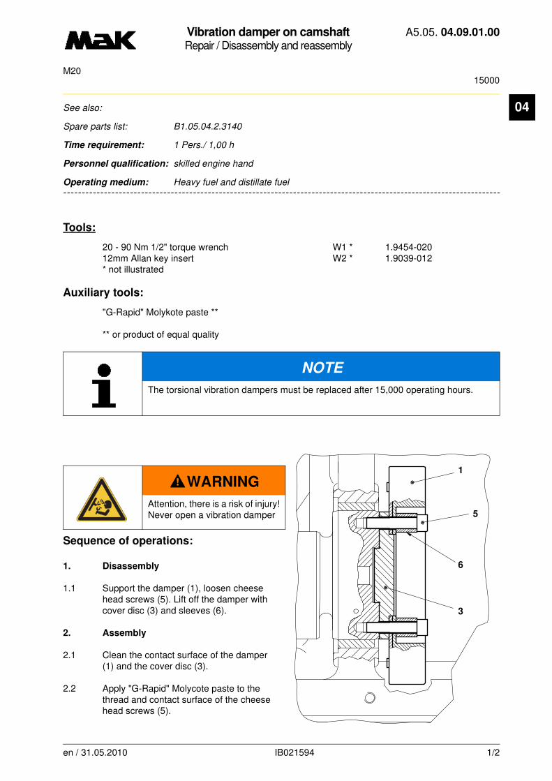
Vibration damper on camshaftRepair / Disassembly and reassembly
A5.05. 04.09.01.00
15000M20
04
-------
See also:
Spare parts list: B1.05.04.2.3140
Time requirement: 1 Pers./ 1,00 h
Personnel qualification: skilled engine hand
-------------------------------------------------------------------------------------------------------------------------
Operating medium: Heavy fuel and distillate fuel
Tools:
20 - 90 Nm 1/2" torque wrench W1 * 1.9454-02012mm Allan key insert W2 * 1.9039-012* not illustrated
Auxiliary tools:
"G-Rapid" Molykote paste **
** or product of equal quality
Sequence of operations:
1. Disassembly
1.1 Support the damper (1), loosen cheese head screws (5). Lift off the damper with cover disc (3) and sleeves (6).
2. Assembly
2.1 Clean the contact surface of the damper (1) and the cover disc (3).
2.2 Apply "G-Rapid" Molycote paste to the thread and contact surface of the cheese head screws (5).
NOTE
The torsional vibration dampers must be replaced after 15,000 operating hours.
WARNING
Attention, there is a risk of injury!Never open a vibration damper 5
1
6
3
en / 31.05.2010 IB021594 1/2

Vibration damper on camshaftRepair / Disassembly and reassembly
A5.05. 04.09.01.00
15000M20
04
2.3 Assemble the cover disc (3), the damper (1), sleeves (6) and cheese head screws (5) according to the illustration.2.4 Tighten the cheese head screws (5) with a torque of
M = 60 Nm.
en / 31.05.2010 IB021594 2/2
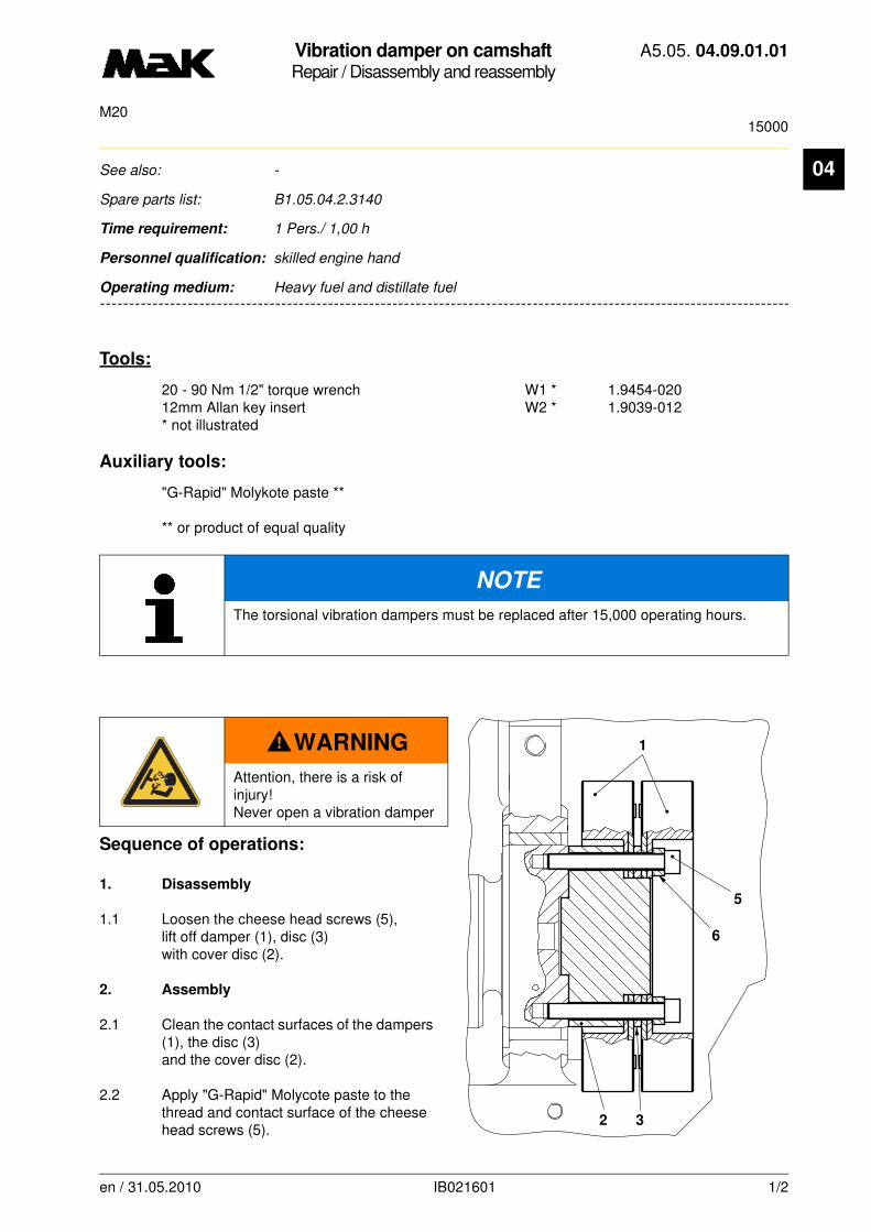
Vibration damper on camshaftRepair / Disassembly and reassembly
A5.05. 04.09.01.01
15000M20
04
-------
See also: -
Spare parts list: B1.05.04.2.3140
Time requirement: 1 Pers./ 1,00 h
Personnel qualification: skilled engine hand
-------------------------------------------------------------------------------------------------------------------------
Operating medium: Heavy fuel and distillate fuel
Tools:
20 - 90 Nm 1/2" torque wrench W1 * 1.9454-02012mm Allan key insert W2 * 1.9039-012* not illustrated
Auxiliary tools:
"G-Rapid" Molykote paste **
** or product of equal quality
Sequence of operations:
1. Disassembly
1.1 Loosen the cheese head screws (5), lift off damper (1), disc (3) with cover disc (2).
2. Assembly
2.1 Clean the contact surfaces of the dampers (1), the disc (3) and the cover disc (2).
2.2 Apply "G-Rapid" Molycote paste to the thread and contact surface of the cheese head screws (5).
NOTE
The torsional vibration dampers must be replaced after 15,000 operating hours.
WARNING
Attention, there is a risk of injury!Never open a vibration damper
6
5
32
1
en / 31.05.2010 IB021601 1/2
Vibration damper on camshaftRepair / Disassembly and reassembly
A5.05. 04.09.01.01
15000M20
04
2.3 Assemble the cover disc, both dampers (1) and disc (3), cheese head screws (5) and sleeves (6) according to the illustration.2.4 Tighten the cheese head screws (5) with a torque of
M = 60 Nm.
en / 31.05.2010 IB021601 2/2

Vibration Damper on CamshaftRepair / Disassembly and reassembly
A5.05. 04.09.01.02
15000M20
04
-------
See also: -
Spare parts list: B1.05.04.2.3140
Time requirement: 1 Pers./ 1,00 h
Personnel qualification: skilled engine hand
-------------------------------------------------------------------------------------------------------------------------
Operating medium: Heavy fuel and distillate fuel
Tools:
Torque wrench 20 - 90 Nm 1/2" W1 * 1.9454-020 Hex cap screw drive A/F12 W2 * 1.9039-012*no illustration
Auxiliary material:
Molykote paste „G-Rapid“ ****or a product of equivalent standard
Sequence of operations:
1. Disassembly
1.1 Support dampers (1 and 2).Loosen cylinder head screws (3).Lift off damper with washers (4 and 5).
1.2 Support cover disk (6). Loosen hexagon socket head cap screws (7).Remove cover disk.
NOTE
After 15.000 operating hours, the vibration dampers have to be exchanged against new ones.
WARNING
Attention, there is a risk of injury!Never open a vibration damper
87
4
9
1021
3
5
6
en / 30.09.2010 IB021607 1/2
Vibration Damper on CamshaftRepair / Disassembly and reassembly
A5.05. 04.09.01.02
15000M20
04
2. Reassembly2.1 Clean contact faces of dampers (1and 2), washers (4 and 5) and cover disk (6).
2.2 Check bores (9) of cover disk (6) and bore (8) of washer (5) for free flow and clean, if necessary.
2.3 Lubricate thread and contact face of cylinder head screws (3 and 7) with Molykote paste „G-Ra-pid“.
2.4 Mount cover disk (6).
2.5 Tighten cylinder head screws (7) with a torque of
M = 60 Nm
2.6 Slip-on damper (1) as shown in the illustration.
2.7 Place washer (5) and align it so that the bores (8 and 9) coincide.
2.8 Mount both dampers (2) with washer (4), cylinder head screws (3) and sleeves (10) in accordan-ce with the illustration.
2.9 Tighten cylinder head screws (5) with a torque of
M = 60 Nm
CAUTION
The free flow of bores (8 and 9) is absolutely necessary to ensure a proper function.
en / 30.09.2010 IB021607 2/2

Control shaft beddingMaintenance / Checking
A5.05. 05.01.02.00
1500M20
en / 10.12.2010 IB026480 1/1
05See also: -
Spare parts list: B1.05.04.2.4110, B1.05.05.2.4210, B1.05.05.2.4521, B1.05.05.2.4523
Time requirement: 1 Pers./ 0,20 h
Personnel qualification: skilled engine hand
--------------------------------------------------------------------------------------------------------------------------------
Operating medium: Heavy fuel and distillate fuel
Maintenance:
Oil control shaft after 1.500 h
Auxiliary material:
Multi-purpose grease or lubricating oil according to A4.05.08.nn
Sequence of operations:
1. Remove control shaft/injection pumps and control station covers.
2. Check control shaft and spindle to emergency-off lever and oil bearing areas slightly with lubrica-ting oil.
3. Oil all moving bearings of the following components slightly:
- swivel head of spring link between control shaft and regulator
- swivel arm between control shaft and injection pump
- dual pivoting bearing of clutch between control station and control shaft
4. Assemble covers.
CAUTION
After cleaning with fat dissolving agents, all bright-metallic components are to be oiled slightly.
Care has to be taken that all cleaned bearings are thoroughly greased.
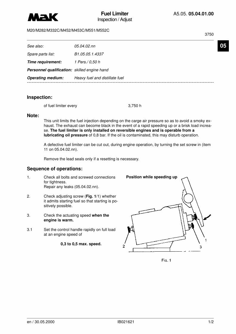
Fuel LimiterInspection / Adjust
A5.05. 05.04.01.00
3750M20/M282/M332C/M452/M453C/M551/M552C
05
-------
See also: 05.04.02.nn
Spare parts list: B1.05.05.1.4337
Time requirement: 1 Pers./ 0,50 h
Personnel qualification: skilled engine hand
-------------------------------------------------------------------------------------------------------------------------
Operating medium: Heavy fuel and distillate fuel
Inspection:
of fuel limiter every 3,750 h
Note:This unit limits the fuel injection depending on the carge air pressure so as to avoid a smoky ex-haust. The exhaust can become black in the event of a rapid speeding up or a brisk load increa-se. The fuel limiter is only installed on reversible engines and is operable from a
lubricating oil pressure of 0,8 bar. If the oil is contaminated, this may disturb operation.
A defective fuel limiter can be cut out, during engine operation, by turning the set screw in (item 11 on 05.04.02.nn).
Remove the lead seals only if a resetting is necessary.
Sequence of operations:
1. Check all bolts and screwed connections for tightness. Repair any leaks (05.04.02.nn).
2. Check adjusting screw (Fig. 1/1) whether it admits starting fuel so that starting is po-sitively possible.
3. Check the actuating speed when the
engine is warm.
3.1 Set the control handle rapidly on full load at an engine speed of
0,3 to 0,5 max. speed.
Position while speeding up
en / 30.05.2000 IB021621 1/2
Fuel LimiterInspection / Adjust
A5.05. 05.04.01.00
3750M20/M282/M332C/M452/M453C/M551/M552C
05
3.2 Check whether the piston follows the charge air pressure change continuously and without hesi-tation. Overhaul the fuel limiter if piston operation is not satisfactory.
Piston travel = 26 mm
3.3 If the exhaust gas becomes black turn adjusting screw (2) 1 to 1.5 turns clockwise to increase the spring load.
3.4 Speed the engine up again and check the exhaust gas.
3.5 If the regulating speed is too slow turn the adjusting screw (2) counterclockwise until the regula-ting speed is as desired without smoke in the exhaust.
4. Check the maximum fuel limiting screw (3) for correct position.
5. Lock the screws.
en / 30.05.2000 IB021621 2/2

Fuel LimiterInspection / Adjust
A5.05. 05.04.01.01
3750M20
05
-------
See also: 05.04.02.nn
Spare parts list: B1.05.05.1.4337
Time requirement: 1 Pers./ 0,50 h
Personnel qualification: skilled engine hand
-------------------------------------------------------------------------------------------------------------------------
Operating medium: Heavy fuel and distillate fuel
Inspection:
of fuel limiter every 3,750 h
Sequence of operations:
1. Check all bolts and screwed connections for tightness. Repair any leaks (05.04.02.nn).
2. Check adjusting screw (Fig. 1/1) whether it admits starting fuel so that starting is po-sitively possible.
3. Check the actuating speed when the
engine is warm.
3.1 Set the control handle rapidly on full load at an engine speed of
0,35 to 0,5 max. speed.
NOTE
This unit limits the fuel injection depending on the carge air pressure so as to avoid a smoky exhaust. The exhaust can become black in the event of a rapid speeding up or a brisk load increase.
en / 31.05.2010 IB021625 1/2
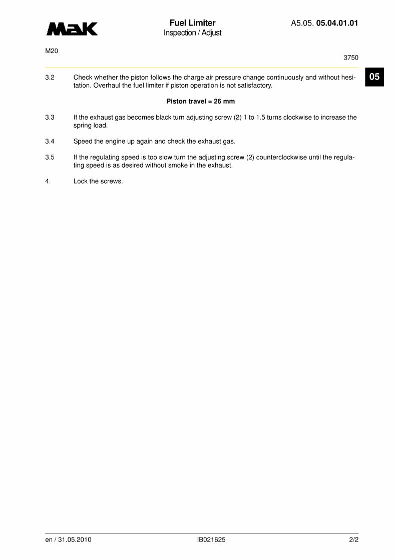
Fuel LimiterInspection / Adjust
A5.05. 05.04.01.01
3750M20
05
3.2 Check whether the piston follows the charge air pressure change continuously and without hesi-tation. Overhaul the fuel limiter if piston operation is not satisfactory.Piston travel = 26 mm
3.3 If the exhaust gas becomes black turn adjusting screw (2) 1 to 1.5 turns clockwise to increase the spring load.
3.4 Speed the engine up again and check the exhaust gas.
3.5 If the regulating speed is too slow turn the adjusting screw (2) counterclockwise until the regula-ting speed is as desired without smoke in the exhaust.
4. Lock the screws.
en / 31.05.2010 IB021625 2/2
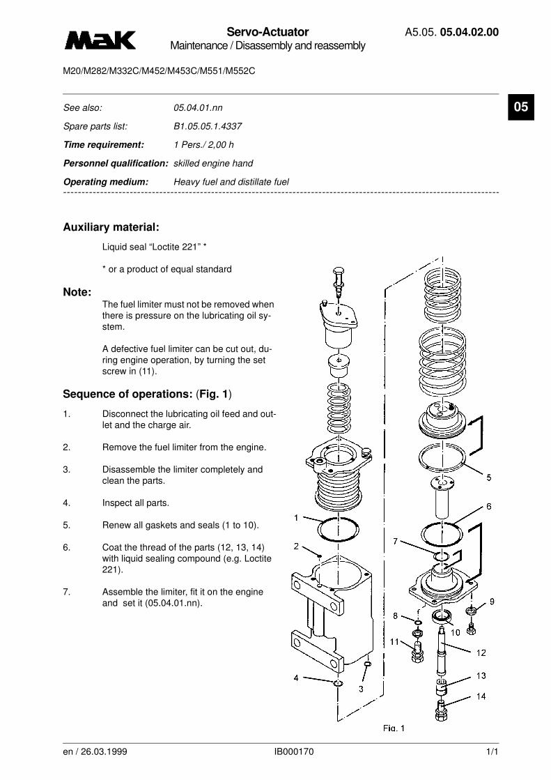
Servo-ActuatorMaintenance / Disassembly and reassembly
A5.05. 05.04.02.00
M20/M282/M332C/M452/M453C/M551/M552C
en / 26.03.1999 IB000170 1/1
05See also: 05.04.01.nn
Spare parts list: B1.05.05.1.4337
Time requirement: 1 Pers./ 2,00 h
Personnel qualification: skilled engine hand
--------------------------------------------------------------------------------------------------------------------------------
Operating medium: Heavy fuel and distillate fuel
Auxiliary material:
Liquid seal “Loctite 221” *
* or a product of equal standard
Note:The fuel limiter must not be removed when there is pressure on the lubricating oil sy-stem.
A defective fuel limiter can be cut out, du-ring engine operation, by turning the set screw in (11).
Sequence of operations: (Fig. 1)
1. Disconnect the lubricating oil feed and out-let and the charge air.
2. Remove the fuel limiter from the engine.
3. Disassemble the limiter completely and clean the parts.
4. Inspect all parts.
5. Renew all gaskets and seals (1 to 10).
6. Coat the thread of the parts (12, 13, 14) with liquid sealing compound (e.g. Loctite 221).
7. Assemble the limiter, fit it on the engine and set it (05.04.01.nn).

Servo-ActuatorMaintenance / Disassembly and reassembly
A5.05. 05.04.02.01
M20
en / 31.05.2010 IB020391 1/1
05See also: 05.04.01.nn
Spare parts list: B1.05.05.1.4337
Time requirement: 1 Pers./ 2,00 h
Personnel qualification: skilled engine hand
--------------------------------------------------------------------------------------------------------------------------------
Operating medium: Heavy fuel and distillate fuel
Auxiliary material:
Liquid seal “Loctite 221” *
* or a product of equal standard
Sequence of operations:
1. Disconnect the lubricating oil feed and out-let and the charge air.
2. Remove the fuel limiter from the engine.
3. Disassemble the limiter completely and clean the parts.
4. Inspect all parts.
5. Renew all gaskets and seals (1 to 10).
6. Coat the thread of the parts (12, 13, 14) with liquid sealing compound (e.g. Loctite 221).
7. Assemble the limiter, fit it on the engine and set it (05.04.01.nn).
CAUTION
The fuel limiter must not be removed when there is pressure on the lubricating oil system.
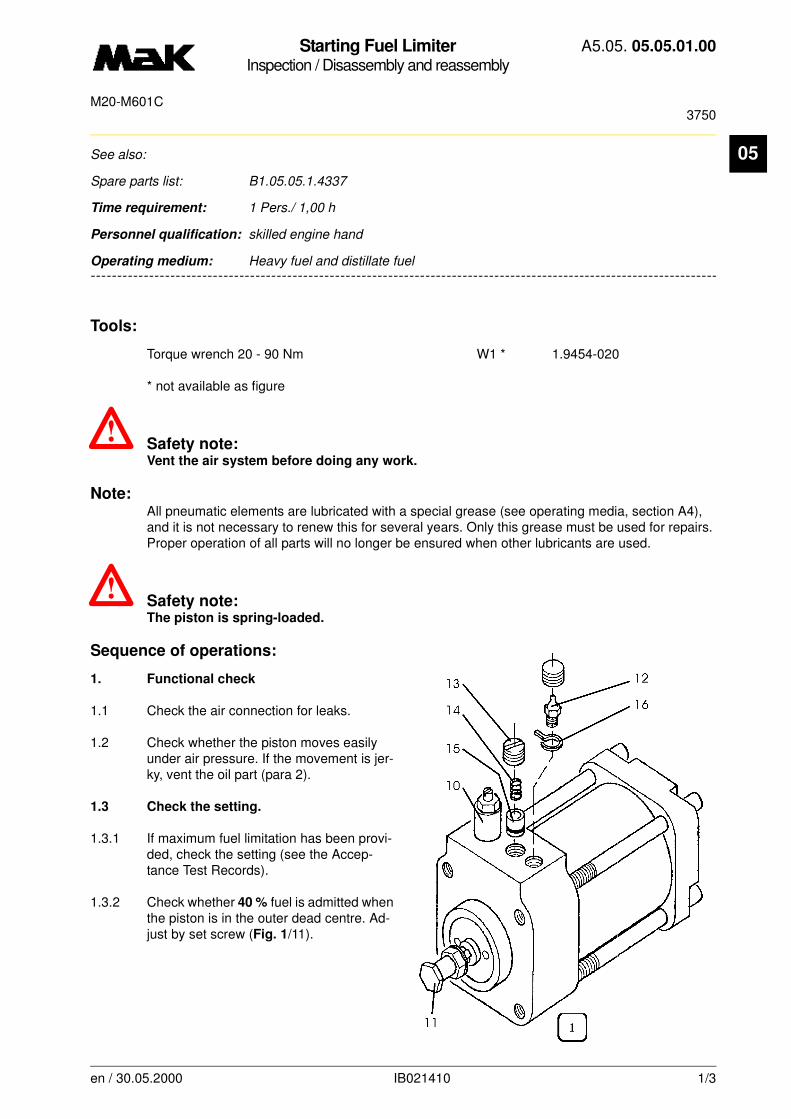
Starting Fuel LimiterInspection / Disassembly and reassembly
A5.05. 05.05.01.00
3750M20-M601C
05
-------
See also:
Spare parts list: B1.05.05.1.4337
Time requirement: 1 Pers./ 1,00 h
Personnel qualification: skilled engine hand
-------------------------------------------------------------------------------------------------------------------------
Operating medium: Heavy fuel and distillate fuel
Tools:
Torque wrench 20 - 90 Nm W1 * 1.9454-020
* not available as figure
~ Safety note:Vent the air system before doing any work.
Note:All pneumatic elements are lubricated with a special grease (see operating media, section A4), and it is not necessary to renew this for several years. Only this grease must be used for repairs. Proper operation of all parts will no longer be ensured when other lubricants are used.
~ Safety note:The piston is spring-loaded.
Sequence of operations:
1. Functional check
1.1 Check the air connection for leaks.
1.2 Check whether the piston moves easily under air pressure. If the movement is jer-ky, vent the oil part (para 2).
1.3 Check the setting.
1.3.1 If maximum fuel limitation has been provi-ded, check the setting (see the Accep-tance Test Records).
1.3.2 Check whether 40 % fuel is admitted when the piston is in the outer dead centre. Ad-just by set screw (Fig. 1/11).
en / 30.05.2000 IB021410 1/3

Starting Fuel LimiterInspection / Disassembly and reassembly
A5.05. 05.05.01.00
3750M20-M601C
05
1.4 Check whether full fuel is admitted within
15 seconds
after starting the engine. Adjust by throttle screw (Fig. 1/10).
2. Venting
2.1 Slip a transparent hose over vent screw (12) and put the other end into a an oil reservoir arranged at a lower level. Turn the vent screw entirely in and then screw one turn back.
2.2 Remove plug (13), spring (14) and piston (15).
2.3 Fill oil in as far as 7 mm below the housing top edge (SAE 20).
2.4 Insert the piston. Drive the air out by screwing the plug in.
2.5 Proceed according to 2.3 and 2.4 until no air escapes any more. Unscrew the plug. Insert the spring. Screw the plug in until it is flush with the housing top edge and secure it with locking spring (16).
2.6 If the cylinder is of the older type, the air must be removed by the throttle screw.
3. Disassembly
3.1 Close the main air valve. Remove the air connection.
3.2 Remove the unit from the engine.
3.3 Measure and note down the position of throttle screw (10) and thrust screw (11).
3.4 Disassemble the unit entirely and clean it in spirit.
3.5 Inspect all parts.
en / 30.05.2000 IB021410 2/3
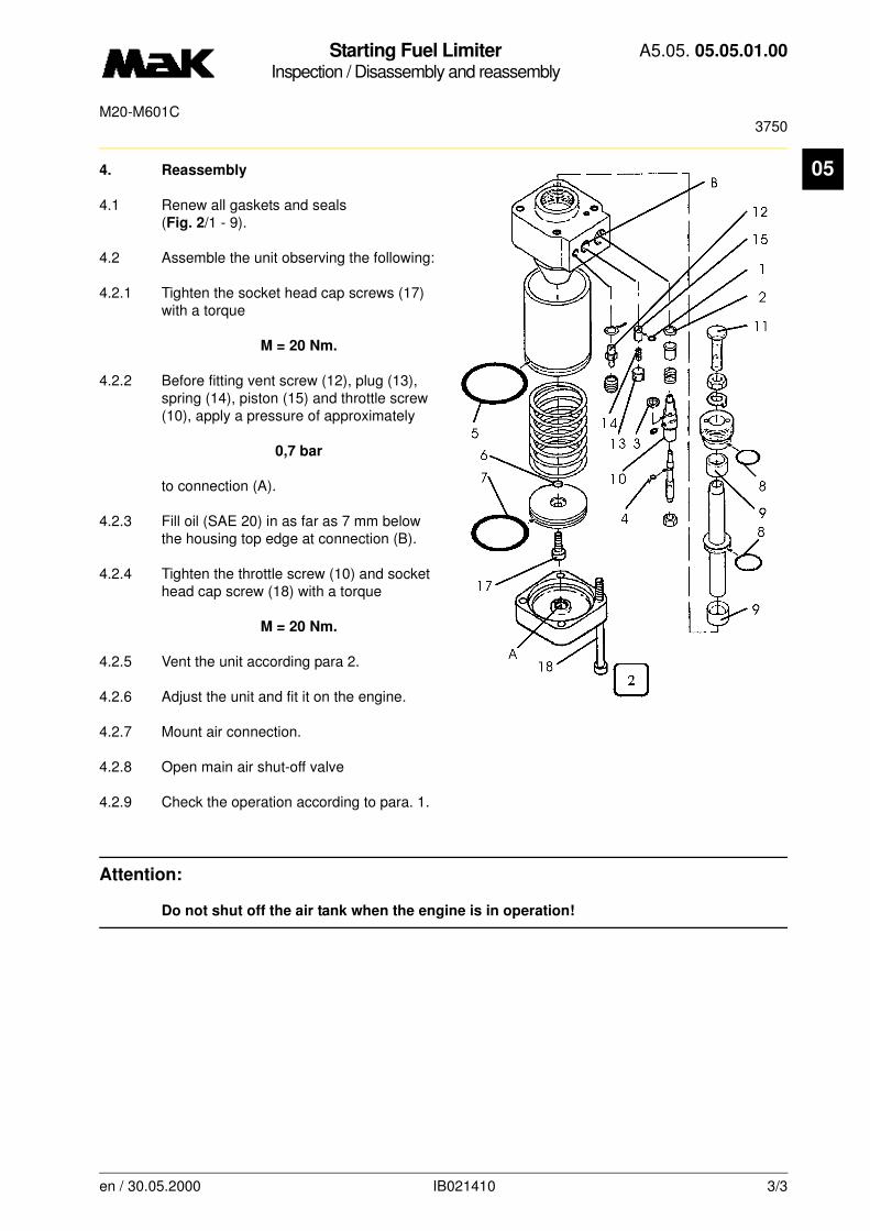
Starting Fuel LimiterInspection / Disassembly and reassembly
A5.05. 05.05.01.00
3750M20-M601C
05
4. Reassembly4.1 Renew all gaskets and seals (Fig. 2/1 - 9).
4.2 Assemble the unit observing the following:
4.2.1 Tighten the socket head cap screws (17) with a torque
M = 20 Nm.
4.2.2 Before fitting vent screw (12), plug (13), spring (14), piston (15) and throttle screw (10), apply a pressure of approximately
0,7 bar
to connection (A).
4.2.3 Fill oil (SAE 20) in as far as 7 mm below the housing top edge at connection (B).
4.2.4 Tighten the throttle screw (10) and socket head cap screw (18) with a torque
M = 20 Nm.
4.2.5 Vent the unit according para 2.
4.2.6 Adjust the unit and fit it on the engine.
4.2.7 Mount air connection.
4.2.8 Open main air shut-off valve
4.2.9 Check the operation according to para. 1.
Attention:
Do not shut off the air tank when the engine is in operation!
en / 30.05.2000 IB021410 3/3
Control ValvesInspection / Checking
A5.05. 05.09.05.00
30000M20
en / 30.09.2010 IB022045 1/1
05See also:
Spare parts list: B1.05.10.2.8614
Time requirement: 1 Pers./ 2,00 h
Personnel qualification: skilled engine hand
--------------------------------------------------------------------------------------------------------------------------------
Operating medium: Heavy fuel and distillate fuel
Inspection:
After four years carry out a random test of the low pressure valves.
In case of deficiencies recondition all control valves.
Special grease for all control units see MaK Lubricant Recommendations in A4.05.08.nn
The use of other lubricants may have a detrimental effect on the functioning of the fittings.
General maintenance instructions see “Description to Functional Diagram” in book C.
This will result in a certain cycle for control or inspection depending on the type and function of the individual control units.
Regulating elements (pressure reducers) must be checked in their circuit after maintenance work for their setting values and must be reset if required.
Ensure that no air is available at the components to be disassembled or that no air can be admitted to these.
Prior to disassembly operations and where necessary, measure and mark the position of valves, lever lengths and lever travels of e.g. actuators, limitations by set screws, and so on.
Do not disassemble control fittings at random since the built-in springs are somtimes prestressed. Where a screw or nut is used for the adjustment of the prestressing, first loosen these completely. Clean the individual components thoroughly and exchange worn down wear parts. During assembly slightly grease rubber rings and their sliding surfaces with the prescribed grease.

Compressed-Air FilterMaintenance / Cleaning
A5.05. 05.09.06.00
24, 150, 7500M20/M25/M32/M43/M453C/M552C/M601C
05
-------
See also:
Spare parts list: B1.05.05.1.4900
Time requirement: 1 Pers./ 0,20 h
Personnel qualification: skilled engine hand
-------------------------------------------------------------------------------------------------------------------------
Operating medium: Heavy fuel and distillate fuel
Maintenance/cleaning:
Drain compressed-air filter: every 24 h
Disassemble and clean compressed-air filter: initially 150 h
Disassemble and clean compressed-air filter: every 7,500 h
Auxiliary material:
Nitro-Solvents *
* or a product of equal standard
CAUTION
Close feed air lines and depressurize air system before every disassembly!
NOTE
It is to be checked to what extent following units/systems (emergency stop) in the circuit are affected in their functioning by the execution of the disassembly and cleaning measures!
en / 25.11.2010 IB021438 1/2
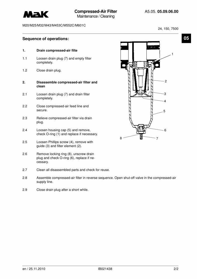
Compressed-Air FilterMaintenance / Cleaning
A5.05. 05.09.06.00
24, 150, 7500M20/M25/M32/M43/M453C/M552C/M601C
05
Sequence of operations:1. Drain compressed-air filte
1.1 Loosen drain plug (7) and empty filter completely.
1.2 Close drain plug.
2. Disassemble compressed-air filter and
clean
2.1 Loosen drain plug (7) and drain filter completely.
2.2 Close compressed-air feed line and secure.
2.3 Relieve compressed-air filter via drain plug.
2.4 Loosen housing cap (5) and remove, check O-ring (1) and replace if necessary.
2.5 Loosen Phillips screw (4), remove with guide (3) and filter element (2).
2.6 Remove locking ring (8), unscrew drain plug and check O-ring (6), replace if ne-cessary.
2.7 Clean all disassembled parts and check for reuse.
2.8 Assemble compressed-air filter in reverse sequence. Open shut-off valve in the compressed-air supply line.
2.9 Close drain plug after a short while.
1
2
3
4
5
6
78
en / 25.11.2010 IB021438 2/2
Compressed-Air FilterMaintenance / Cleaning
A5.05. 05.09.06.01
24, 7500M20/M25/M32/M43
en / 25.11.2010 IB024847 1/1
05See also: C5.05.05.45.23.nn
Spare parts list: B1.05.05.9.4523
Time requirement: 1 Pers./ 0,20 h
Personnel qualification: skilled engine hand
--------------------------------------------------------------------------------------------------------------------------------
Operating medium: Heavy fuel and distillate fuel
Maintenance/cleaning:
Drain compressed-air filter: every 24 h
Disassemble and clean compressed-air filter: initially 150 h
Disassemble and clean compressed-air filter: every 7,500 h
NOTE
Maintenance and trouble shooting see "engine documentation, chapter "Control/Regulation" C5.05.05.45.23.nn

ReglerölInspection / Oil change
A5.05. 05.25.00.01
24M20/M25/M32/M43
en / 25.08.2006 IB025366 1/1
05See also: C5.05.04.20.27.nn
Spare parts list:
Time requirement: 1 Pers./ 0,05 h
Personnel qualification: skilled engine hand
--------------------------------------------------------------------------------------------------------------------------------
Operating medium: Every fuel
Check: Visual check of the governor oil every 24 h
Attention: A visual check of the governor oil must be carried out every 24 hours on the oil level sight
glass of the governor.
If the governor oil should show obvious contamination, it must be changed forthwith.
Note: For further information and evaluation criteria please refer to the oil specificationin Book C (C5.05.04.20.27.nn).

Exhaust ManifoldMaintenance / Disassembly and reassembly
A5.05. 06.01.01.00
30000, 7500M20
06
-------
See also:
Spare parts list: B1.05.06.2.72n0
Time requirement: 1 Pers./ 3,00 h
Personnel qualification: skilled engine hand
-------------------------------------------------------------------------------------------------------------------------
Operating medium: Heavy fuel and distillate fuel
Inspection:
Exhaust manifolds must be examined for leakages after 7,500 h
Maintenance:
Remove and clean exhaust manifold after 30,000 h
Auxiliary material:
High temperature-thread paste “Dag S-5080” *
* or a product of equal standard
Sequence of operations:
1. Inspection
1.1 Remove the covering from the exhaust manifold.
1.2 Check all bolts for tightness.
1.3 Carry out a visual inspection at the flanged connections and expansion joints (inspection must be carried out with the engine running).
NOTE
Check also the exhaust piping after the turbocharger when doing the work on the ex-haust manifold.
If excessive vibrations and noises occur in the exhaust-gas turbine, the flanged con-nection on the exhaust pipe behind the turbine must be unscrewed and examined for pipe tension.
To safeguard the expansion joints these must not be subjected to bending or radial forces on removal and fitting. A small preload (expansion), however, is necessary in axial direction when installing (about 3mm).
Fit all screws with high temperature-thread paste “Dag S-5080” to avoid sticking due to heat.
en / 31.05.2010 IB022083 1/2

Exhaust ManifoldMaintenance / Disassembly and reassembly
A5.05. 06.01.01.00
30000, 7500M20
06
1.4 Fit the covering.
2. Maintenance
2.1 Remove covering and carry out inspections according to 1.3. Mark the mounting position of the expansion joints and pipes.
2.2 Remove the exhaust manifold.
2.2.1 Loosen the flanged connections first at the expansion joint (Fig. 1/1), then at the cylinder head (2) and remove the pipe.
2.3 Clean the inside of the exhaust manifolds and check for cracks.
2.4 Check the expansion joints and replace them if necessary.
2.5 Fit the exhaust manifolds with new gaskets in reverse order and observe the markings.
2.6 Coat the thread and screw contact surface of the screws with “Dag S-5080”. Screw in the screws with resilient sleeves and tighten on alternate sides in two stages with a
torque of 60 Nm and 110 Nm.
2.7 Fit the expansion joints after precise adjustment of the pipes (direction of flow marked with arrow).
2.8 Fit the covering.
NOTE
Soot and soot deposits indicate a leak of the system. Renew the gaskets if no cracks in the pipes or slack bolts are the cause of the leak. Replace expansion joints that have cracks in the bellows. On assembly pay attention to the direction of flow
(arrow on the flange).
2 1
Fig. 1
en / 31.05.2010 IB022083 2/2

Exhaust ManifoldMaintenance / Disassembly and reassembly
A5.05. 06.01.01.01
7500M20
06
-------
See also:
Spare parts list: B1.05.06.2.72n0
Time requirement: 1 Pers./ 3,00 h
Personnel qualification: skilled engine hand
-------------------------------------------------------------------------------------------------------------------------
Operating medium: Heavy fuel and distillate fuel
Checks:
Check exhaust pipe for leaks after 7,500 hrs
Auxiliary material:
High temperature bolt lubricant "Rivolta G.W.F“ *
* or comparable product
Procedure:
1. Remove exhaust pipe sheathing.
2. Check tightness of all bolt connections.
NOTE
In order to prevent longitudinal strain of the expansion joints, they should not be sub-jected to bending and/or radial forces during disassembly and assembly. However, for the expansion joint ahead of the turbine, a slight preload in axial direc-tion (strain) is required during installation.
Coat all bolts with high temperature bolt lubricant "Rivolta G.W.F." before installation in order to protect them from seizure.
DANGER
Caution, hot engine components can cause burns! Always check temperatures before beginning work on exhaust pipes! Let exhaust piping cool sufficiently!
en / 30.09.2010 IB025358 1/3
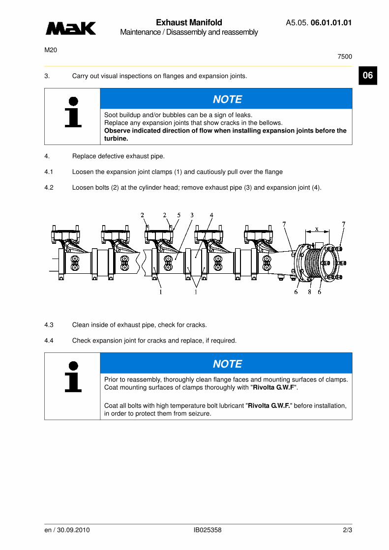
Exhaust ManifoldMaintenance / Disassembly and reassembly
A5.05. 06.01.01.01
7500M20
06
3. Carry out visual inspections on flanges and expansion joints.4. Replace defective exhaust pipe.
4.1 Loosen the expansion joint clamps (1) and cautiously pull over the flange
4.2 Loosen bolts (2) at the cylinder head; remove exhaust pipe (3) and expansion joint (4).
4.3 Clean inside of exhaust pipe, check for cracks.
4.4 Check expansion joint for cracks and replace, if required.
NOTE
Soot buildup and/or bubbles can be a sign of leaks. Replace any expansion joints that show cracks in the bellows. Observe indicated direction of flow when installing expansion joints before the
turbine.
NOTE
Prior to reassembly, thoroughly clean flange faces and mounting surfaces of clamps.Coat mounting surfaces of clamps thoroughly with "Rivolta G.W.F".
Coat all bolts with high temperature bolt lubricant "Rivolta G.W.F." before installation, in order to protect them from seizure.
en / 30.09.2010 IB025358 2/3

Exhaust ManifoldMaintenance / Disassembly and reassembly
A5.05. 06.01.01.01
7500M20
06
4.5 Install exhaust pipe (3) with expansion joint (4) and new seal (5).4.6 Coat threads and washer face of bolts (2) with "Rivolta G.W.F". Insert bolts with extension slee-ves in cylinder head and tighten alternately in 2 steps with a tightening torque of
M = 60 and 110 Nm
.
4.7 Coat mounting surfaces of clamps with "Rivolta G.W.F".
4.8 Cautiously pull clamps over the flanges
4.9 Tighten clamps with a tightening torque of
M = 25 Nm
.
4.10 When mounting the expansion joint (8) ahead of the turbine, fabricate a dummy.
Length of dummy x = 180 mm
4.11 Mount exhaust pipe with new seal and dummy.
4.12 Coat threads and washer face of bolts with "Rivolta G.W.F". Insert bolts with extension sleeves in cylinder head and tighten alternately in 2 steps with a tightening torque of
M = 60 and 110 Nm
.
4.13 Remove dummy
4.14 Mount expansion tube; note the direction of flow as identified by the arrow on the flange.
4.15 Coat threads and washer face of bolts (6) with "Rivolta G.W.F".
4.16 Fit bolts (6) from the expansion joint side.
4.17 Mount extension sleeves with hexagonal nuts (7) from the exhaust pipe side.
4.18 Tighten bolts with a tightening torque of M = 90 Nm
4.19 Install exhaust pipe sheathing.
CAUTION
The arrow on the expansion joint flange must point in the direction of flow
en / 30.09.2010 IB025358 3/3
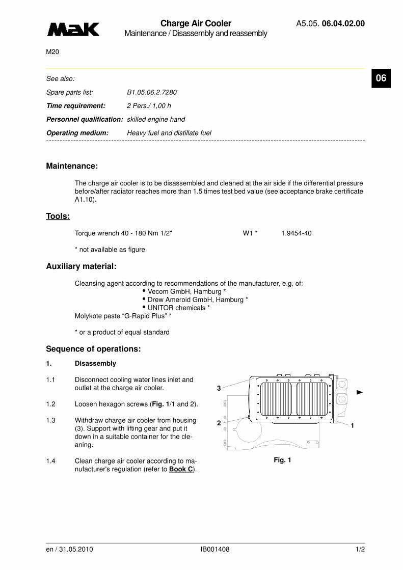
Charge Air CoolerMaintenance / Disassembly and reassembly
A5.05. 06.04.02.00
M20
06
-------
See also:
Spare parts list: B1.05.06.2.7280
Time requirement: 2 Pers./ 1,00 h
Personnel qualification: skilled engine hand
-------------------------------------------------------------------------------------------------------------------------
Operating medium: Heavy fuel and distillate fuel
Maintenance:
The charge air cooler is to be disassembled and cleaned at the air side if the differential pressure before/after radiator reaches more than 1.5 times test bed value (see acceptance brake certificate A1.10).
Tools:
Torque wrench 40 - 180 Nm 1/2" W1 * 1.9454-40
* not available as figure
Auxiliary material:
Cleansing agent according to recommendations of the manufacturer, e.g. of:• Vecom GmbH, Hamburg *• Drew Ameroid GmbH, Hamburg *• UNITOR chemicals *
Molykote paste “G-Rapid Plus” *
* or a product of equal standard
Sequence of operations:
1. Disassembly
1.1 Disconnect cooling water lines inlet and outlet at the charge air cooler.
1.2 Loosen hexagon screws (Fig. 1/1 and 2).
1.3 Withdraw charge air cooler from housing (3). Support with lifting gear and put it down in a suitable container for the cle-aning.
1.4 Clean charge air cooler according to ma-nufacturer's regulation (refer to Book C).
1
3
Fig. 1
2
en / 31.05.2010 IB001408 1/2

Charge Air CoolerMaintenance / Disassembly and reassembly
A5.05. 06.04.02.00
M20
06
2. Reassembly
2.1 Carry out reassembly in reverse order to disassembly.
2.2 Renew all seals.
2.3 Lubricate hexagon screws (Fig. 1/2) with Molykote paste “G-Rapid Plus” and tighten with a torque of
M = 60 Nm.
WARNING
Observe regulations of the manufacturer for cleansing agent to be used, protect skin against contact with cleansing agent, wear safety glasses. Ensure good ventilation.
NOTE
Ensure proper fit of the sealing plates in the housing.
en / 31.05.2010 IB001408 2/2

Charge Air CoolerMaintenance / Disassembly and reassembly
A5.05. 06.04.02.01
M20
06
-------
See also:
Spare parts list: B1.05.06.2.7240
Time requirement: 2 Pers./ 1,00 h
Personnel qualification: skilled engine hand
-------------------------------------------------------------------------------------------------------------------------
Operating medium: Heavy fuel and distillate fuel
Maintenance:
The charge air cooler is to be disassembled and cleaned at the air side if the differential pressure before/after radiator reaches more than 1.5 times test bed value (see acceptance brake certificate A1.10).
Tools:
Torque wrench 40 - 180 Nm 1/2" W1 * 1.9454-40
* not available as figure
Auxiliary material:
Cleansing agent according to recommendations of the manufacturer, e.g. of:• Vecom GmbH, Hamburg *• Drew Ameroid GmbH, Hamburg *• UNITOR chemicals *
Molykote paste “G-Rapid Plus” *
* or a product of equal standard
Sequence of operations:
1. Disassembly
1.1 Disconnect cooling water lines inlet and outlet at the charge air cooler.
1.2 Loosen hexagon screws (Fig. 1/1 and 2).
1.3 Withdraw charge air cooler from housing (3). Support with lifting gear and put it down in a suitable container for the cle-aning.
1.4 Clean charge air cooler according to ma-nufacturer's regulation (refer to Book C).
1
3
Fig. 1
2
en / 31.05.2010 IB002304 1/2
Charge Air CoolerMaintenance / Disassembly and reassembly
A5.05. 06.04.02.01
M20
06
2. Reassembly
2.1 Carry out reassembly in reverse order to disassembly.
2.2 Renew all seals.
2.3 Lubricate hexagon screws (Fig. 1/2) with Molykote paste “G-Rapid Plus” and tighten with a torque of
M = 60 Nm.
WARNING
Observe regulations of the manufacturer for cleansing agent to be used, protect skin against contact with cleansing agent, wear safety glasses. Ensure good ventilation.
NOTE
Ensure proper fit of the sealing plates in the housing.
en / 31.05.2010 IB002304 2/2
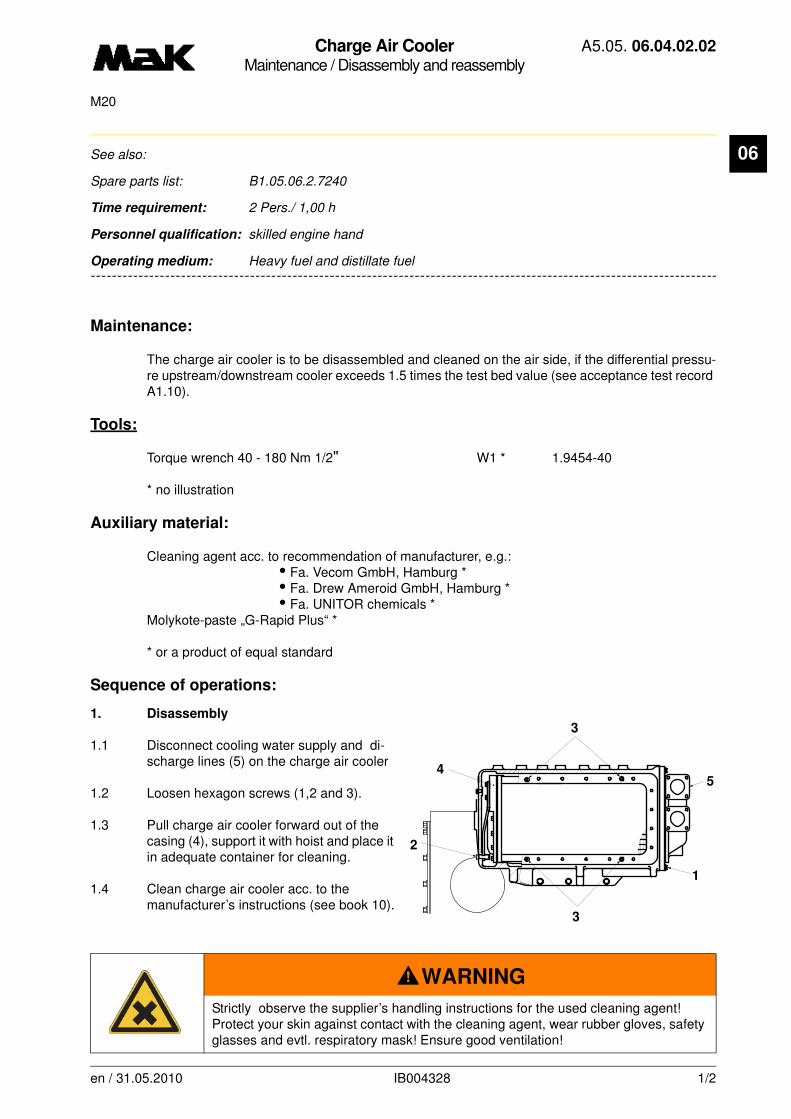
Charge Air CoolerMaintenance / Disassembly and reassembly
A5.05. 06.04.02.02
M20
06
-------
See also:
Spare parts list: B1.05.06.2.7240
Time requirement: 2 Pers./ 1,00 h
Personnel qualification: skilled engine hand
-------------------------------------------------------------------------------------------------------------------------
Operating medium: Heavy fuel and distillate fuel
Maintenance:
The charge air cooler is to be disassembled and cleaned on the air side, if the differential pressu-re upstream/downstream cooler exceeds 1.5 times the test bed value (see acceptance test record A1.10).
Tools:
Torque wrench 40 - 180 Nm 1/2" W1 * 1.9454-40
* no illustration
Auxiliary material:
Cleaning agent acc. to recommendation of manufacturer, e.g.:• Fa. Vecom GmbH, Hamburg *• Fa. Drew Ameroid GmbH, Hamburg *• Fa. UNITOR chemicals *
Molykote-paste „G-Rapid Plus“ *
* or a product of equal standard
Sequence of operations:
1. Disassembly
1.1 Disconnect cooling water supply and di-scharge lines (5) on the charge air cooler
1.2 Loosen hexagon screws (1,2 and 3).
1.3 Pull charge air cooler forward out of the casing (4), support it with hoist and place it in adequate container for cleaning.
1.4 Clean charge air cooler acc. to the manufacturer’s instructions (see book 10).
WARNING
Strictly observe the supplier’s handling instructions for the used cleaning agent! Protect your skin against contact with the cleaning agent, wear rubber gloves, safety glasses and evtl. respiratory mask! Ensure good ventilation!
5
3
3
4
2
1
en / 31.05.2010 IB004328 1/2
Charge Air CoolerMaintenance / Disassembly and reassembly
A5.05. 06.04.02.02
M20
06
2. Reassembly2.1 Renew all gaskets
2.2 Grease hexagon screws (1,2 and 3) with Molykote paste „G-Rapid Plus“.
2.3 Secure charge air cooler on hoist and push cooler into casing
Strictly observe the tightening instructions for hexagon screws (1, 2 and 3).
2.4 Mount hexagon screws (1 and 3) and slightly tighten them crosswise to provide for uniform contact of the charge air cooler on front and sides.
2.5 Tighten hexagon screws (1) crosswise in small steps up to a torque of
M = 60 Nm.
2.6 Tighten hexagon screws (3) crosswise in small steps up to a torque of
M = 60 Nm.
2.7 Mount hexagon screws (2) and tightem them crosswise in small steps up to a torque of
M = 60 Nm.
en / 31.05.2010 IB004328 2/2
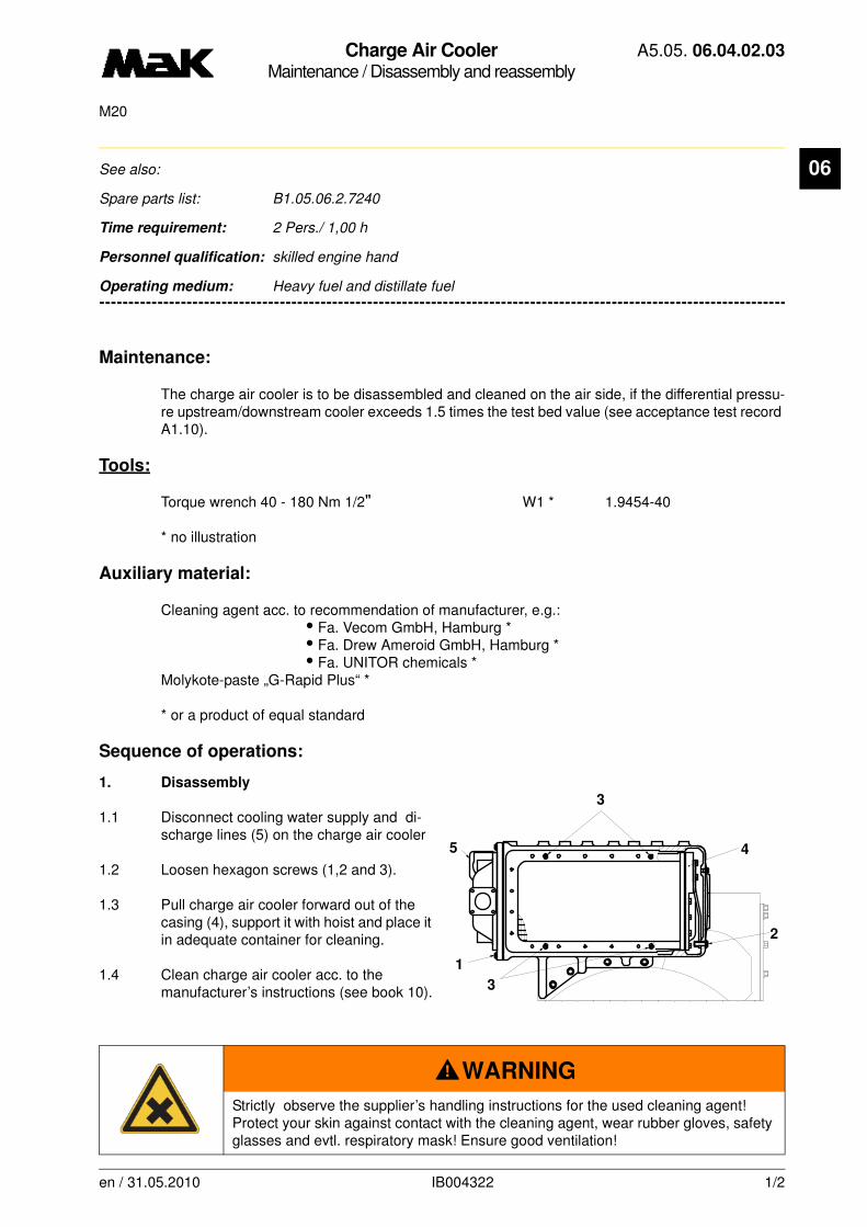
Charge Air CoolerMaintenance / Disassembly and reassembly
A5.05. 06.04.02.03
M20
06
-------
See also:
Spare parts list: B1.05.06.2.7240
Time requirement: 2 Pers./ 1,00 h
Personnel qualification: skilled engine hand
-------------------------------------------------------------------------------------------------------------------------
Operating medium: Heavy fuel and distillate fuel
Maintenance:
The charge air cooler is to be disassembled and cleaned on the air side, if the differential pressu-re upstream/downstream cooler exceeds 1.5 times the test bed value (see acceptance test record A1.10).
Tools:
Torque wrench 40 - 180 Nm 1/2" W1 * 1.9454-40
* no illustration
Auxiliary material:
Cleaning agent acc. to recommendation of manufacturer, e.g.:• Fa. Vecom GmbH, Hamburg *• Fa. Drew Ameroid GmbH, Hamburg *• Fa. UNITOR chemicals *
Molykote-paste „G-Rapid Plus“ *
* or a product of equal standard
Sequence of operations:
1. Disassembly
1.1 Disconnect cooling water supply and di-scharge lines (5) on the charge air cooler
1.2 Loosen hexagon screws (1,2 and 3).
1.3 Pull charge air cooler forward out of the casing (4), support it with hoist and place it in adequate container for cleaning.
1.4 Clean charge air cooler acc. to the manufacturer’s instructions (see book 10).
WARNING
Strictly observe the supplier’s handling instructions for the used cleaning agent! Protect your skin against contact with the cleaning agent, wear rubber gloves, safety glasses and evtl. respiratory mask! Ensure good ventilation!
2
3
4
1
3
5
en / 31.05.2010 IB004322 1/2

Charge Air CoolerMaintenance / Disassembly and reassembly
A5.05. 06.04.02.03
M20
06
2. Reassembly2.1 Renew all gaskets
2.2 Grease hexagon screws (1,2 and 3) with Molykote paste „G-Rapid Plus“.
2.3 Secure charge air cooler on hoist and push cooler into casing
Strictly observe the tightening instructions for hexagon screws (1, 2 and 3).
2.4 Mount hexagon screws (1 and 3) and slightly tighten them crosswise to provide for uniform contact of the charge air cooler on front and sides.
2.5 Tighten hexagon screws (1) crosswise in small steps up to a torque of
M = 60 Nm.
2.6 Tighten hexagon screws (3) crosswise in small steps up to a torque of
M = 60 Nm.
2.7 Mount hexagon screws (2) and tightem them crosswise in small steps up to a torque of
M = 60 Nm.
en / 31.05.2010 IB004322 2/2

Charge Air CoolerMaintenance / Disassembly and reassembly
A5.05. 06.04.02.04
M20
06
-------
See also:
Spare parts list: B1.05.06.2.7250
Time requirement: 2 Pers./ 1,00 h
Personnel qualification: skilled engine hand
-------------------------------------------------------------------------------------------------------------------------
Operating medium: Heavy fuel and distillate fuel
Maintenance:The charge air cooler must be removed and cleaned on the air side when the differential pressure before/after the cooler exceeds 1.5 times the test bench value (see acceptance brake certificate A1.10).
Auxiliary materials:Cleaning agent as recommended by the manufacturer, such as:
• Vecom GmbH, Hamburg *• Drew Ameroid GmbH, Hamburg *• UNITOR chemicals *
Molykote Paste "G-Rapid Plus“ *
* or equivalent product
Procedure:
1. Disassembly
1.1 Loosen the bleeder bolts, or for engines with continual bleeding, ensure that the corresponding cock valves are open, re-move the drain bolts (Fig. 1/5) and drain water from charge air cooler.
1.2 Remove the coolant feed and return li-nes(4) from the charge air cooler.
en / 30.09.2010 IB025507 1/3
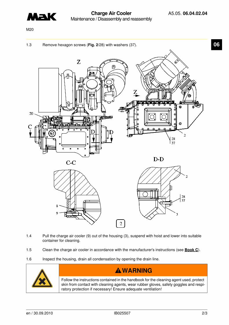
Charge Air CoolerMaintenance / Disassembly and reassembly
A5.05. 06.04.02.04
M20
06
1.3 Remove hexagon screws (Fig. 2/28) with washers (37).1.4 Pull the charge air cooler (9) out of the housing (3), suspend with hoist and lower into suitable container for cleaning.
1.5 Clean the charge air cooler in accordance with the manufacturer's instructions (see Book C).
1.6 Inspect the housing, drain all condensation by opening the drain line.
WARNING
Follow the instructions contained in the handbook for the cleaning agent used, protect skin from contact with cleaning agents, wear rubber gloves, safety goggles and respi-ratory protection if necessary! Ensure adequate ventilation!
en / 30.09.2010 IB025507 2/3

Charge Air CoolerMaintenance / Disassembly and reassembly
A5.05. 06.04.02.04
M20
06
2. Assembly2.1 Install charge air cooler in the reverse order as disassembly.
2.2 Insert new O-ring (8) into O-ring sheet (9).
2.3 Slide charge air cooler (2) into the housing (3) carefully.
2.4 Insert hexagon screws (28) with washers (37).
2.5 Tighten hexagon screws (28) one after the other to a torque of
M = 52 Nm.
2.6 Attach coolant supply and return lines (4) to the charge air cooler.
2.7 Tighten drain bolts (5) and fill engine completely with coolant.
2.8 Tighten bleeder bolts or the corresponding cock valves tightly.
NOTE
Apply a light coat of Molykote paste “G-Rapid Plus” to the contact surfaces and threads of all bolts.
en / 30.09.2010 IB025507 3/3
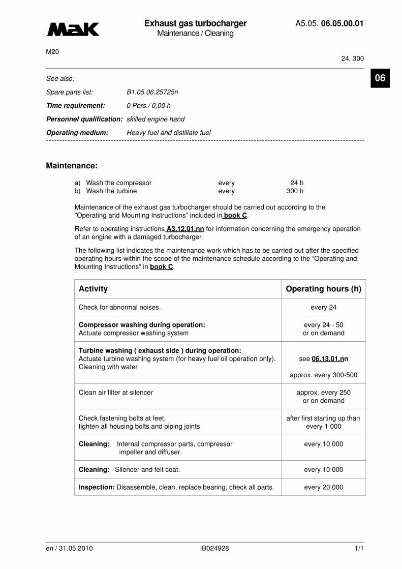
Exhaust gas turbochargerMaintenance / Cleaning
A5.05. 06.05.00.01
24, 300M20
en / 31.05.2010 IB024928 1/1
06See also:
Spare parts list: B1.05.06.25725n
Time requirement: 0 Pers./ 0,00 h
Personnel qualification: skilled engine hand
--------------------------------------------------------------------------------------------------------------------------------
Operating medium: Heavy fuel and distillate fuel
Maintenance:
a) Wash the compressor every 24 hb) Wash the turbine every 300 h
Maintenance of the exhaust gas turbocharger should be carried out according to the ”Operating and Mounting Instructions” included in book C.
Refer to operating instructions A3.12.01.nn for information concerning the emergency operation of an engine with a damaged turbocharger.
The following list indicates the maintenance work which has to be carried out after the specified operating hours within the scope of the maintenance schedule according to the “Operating and Mounting Instructions“ in book C.
Activity Operating hours (h)
Check for abnormal noises. every 24
Compressor washing during operation:
Actuate compressor washing systemevery 24 - 50or on demand
Turbine washing ( exhaust side ) during operation:
Actuate turbine washing system (for heavy fuel oil operation only).Cleaning with water
see 06.13.01.nn
approx. every 300-500
Clean air filter at silencer approx. every 250or on demand
Check fastening bolts at feet,tighten all housing bolts and piping joints
after first starting up than every 1 000
Cleaning: Internal compressor parts, compressorimpeller and diffuser.
every 10 000
Cleaning: Silencer and felt coat. every 10 000
Inspection: Disassemble, clean, replace bearing, check all parts. every 20 000

Exhaust gas turbochargerMaintenance / Cleaning
A5.05. 06.05.01.01
24M20
06
-------
See also: A5.05.06.13.01.nn, A3.06.06.nn
Spare parts list: B1.05.06.nn7259 nn
Time requirement: 1 Pers./ 0,40 h
Personnel qualification: skilled engine hand
-------------------------------------------------------------------------------------------------------------------------
Operating medium: Heavy fuel and distillate fuel
Maintenance:
Compressor cleaning M 20 every 24 h
Prerequisites:
-The compressor stage must be cleaned with the engine at operating temperature and under full load (> 85% load ), if possible; i.e., at high turbocharger rpm.
- Clean pipes from the charge air system and after each turbocharger.
Air side washing device operating instructions:
Basic position:
- Washing water container (3) : empty
- Cap (2) : closed
Washing procedure:
1. Remove thumb nut (1) with cap (2).
1.1 Fill washing water container (3) with clean water.
1.2 Install cap (2) with thumb nut (1).
NOTE
Deposits or dirt praticles inside the washing system can plug the nozzles and nega-tively impact cleaning success.
CAUTION
A washing water container that has been locked insufficiently or not at all may cause injury or death of the operator.
en / 30.09.2010 IB025455 1/3
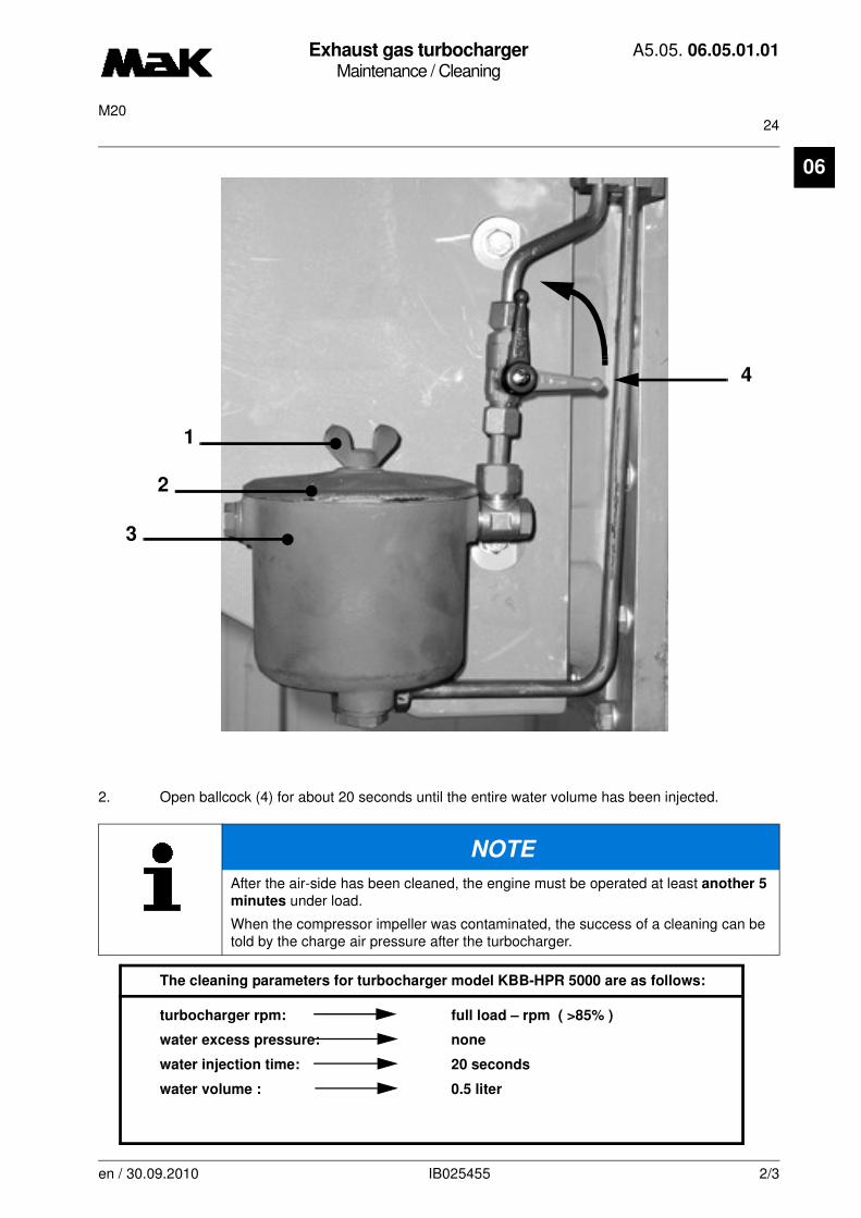
Exhaust gas turbochargerMaintenance / Cleaning
A5.05. 06.05.01.01
24M20
06
2. Open ballcock (4) for about 20 seconds until the entire water volume has been injected.
The cleaning parameters for turbocharger model KBB-HPR 5000 are as follows:
turbocharger rpm: full load – rpm ( >85% )
water excess pressure: none
water injection time: 20 seconds
water volume : 0.5 liter
NOTE
After the air-side has been cleaned, the engine must be operated at least another 5
minutes under load.
When the compressor impeller was contaminated, the success of a cleaning can be told by the charge air pressure after the turbocharger.
1
2
3
4
en / 30.09.2010 IB025455 2/3

Exhaust gas turbochargerMaintenance / Cleaning
A5.05. 06.05.01.01
24M20
06
Additional details on the exhaust turbocharger may be found in the maintenance instructions in book C or in the operator’s manual of the turbocharger manufacturer.
CAUTION
Because of the increased risk of corrosion, only clear water (drinking water) -
never salt water - must be used for cleaning. This water should not contain any
coolant treatments or other chemicals that may form deposits in the air ducts.
CAUTION
The injection tube must never be connected directly to a water line, a different
or larger metering container or to a larger washing water containerother than the
one provided by Caterpillar Motoren.
CAUTION
Avoid getting uncontrolled amounts of water into the turbocharger or the engine. This can cause personal injury and major damage.
en / 30.09.2010 IB025455 3/3
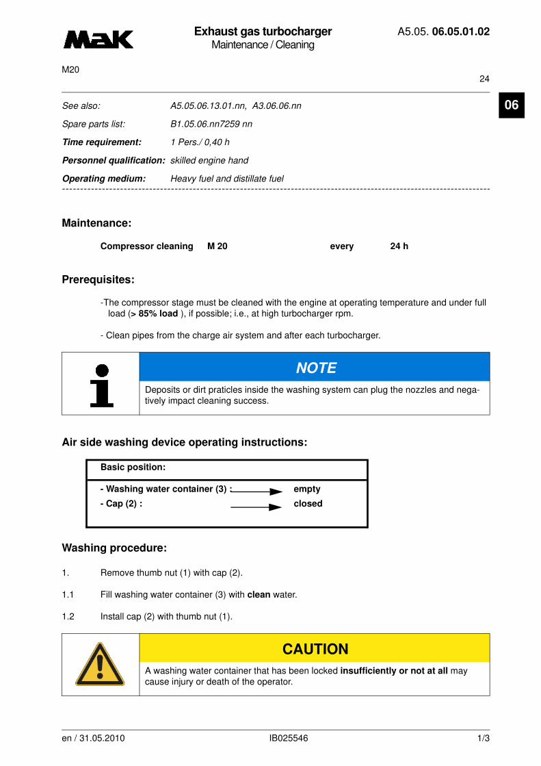
Exhaust gas turbochargerMaintenance / Cleaning
A5.05. 06.05.01.02
24M20
06
-------
See also: A5.05.06.13.01.nn, A3.06.06.nn
Spare parts list: B1.05.06.nn7259 nn
Time requirement: 1 Pers./ 0,40 h
Personnel qualification: skilled engine hand
-------------------------------------------------------------------------------------------------------------------------
Operating medium: Heavy fuel and distillate fuel
Maintenance:
Compressor cleaning M 20 every 24 h
Prerequisites:
-The compressor stage must be cleaned with the engine at operating temperature and under full load (> 85% load ), if possible; i.e., at high turbocharger rpm.
- Clean pipes from the charge air system and after each turbocharger.
Air side washing device operating instructions:
Basic position:
- Washing water container (3) : empty
- Cap (2) : closed
Washing procedure:
1. Remove thumb nut (1) with cap (2).
1.1 Fill washing water container (3) with clean water.
1.2 Install cap (2) with thumb nut (1).
NOTE
Deposits or dirt praticles inside the washing system can plug the nozzles and nega-tively impact cleaning success.
CAUTION
A washing water container that has been locked insufficiently or not at all may cause injury or death of the operator.
en / 31.05.2010 IB025546 1/3

Exhaust gas turbochargerMaintenance / Cleaning
A5.05. 06.05.01.02
24M20
06
2. Open ballcock (4) for about 20 seconds until the entire water volume has been injected.
The cleaning parameters for turbocharger model KBB-HPR 4000 are as follows:
turbocharger rpm: full load – rpm ( >85% )
water excess pressure: none
water injection time: 20 seconds
water volume : 0.5 liter
NOTE
After the air-side has been cleaned, the engine must be operated at least another 5
minutes under load.
When the compressor impeller was contaminated, the success of a cleaning can be told by the charge air pressure after the turbocharger.
1
2
3
4
en / 31.05.2010 IB025546 2/3
Exhaust gas turbochargerMaintenance / Cleaning
A5.05. 06.05.01.02
24M20
06
Additional details on the exhaust turbocharger may be found in the maintenance instructions in book C or in the operator’s manual of the turbocharger manufacturer.
CAUTION
Because of the increased risk of corrosion, only clear water (drinking water) -
never salt water - must be used for cleaning. This water should not contain any
coolant treatments or other chemicals that may form deposits in the air ducts.
CAUTION
The injection tube must never be connected directly to a water line, a different
or larger metering container or to a larger washing water containerother than the
one provided by Caterpillar Motoren.
CAUTION
Avoid getting uncontrolled amounts of water into the turbocharger or the engine. This can cause personal injury and major damage.
en / 31.05.2010 IB025546 3/3

Exhaust gas turbochargerMaintenance / Cleaning
A5.05. 06.05.02.03
150M20
06
-------
See also: A5.05.06.05.00.nn, A3.06.06.nn
Spare parts list: B1.05.06.nn7259 nn
Time requirement: 1 Pers./ 0,40 h
Personnel qualification: skilled engine hand
-------------------------------------------------------------------------------------------------------------------------
Operating medium: Heavy fuel
Maintenance:
Turbine cleaning M 20 every 150 h
Prerequisite: - Wet cleaning
wet cleaning of turbine and nozzle ring require lower exhaust gas temperatures or lower engine load*.
* Definition of low engine load:
Low engine load means that the engine either
- runs at zero pitch and rated rpm- runs on the grid at rated rpm and max. 10 % load- runs disengaged at rated rpm- for fixed impellers at max. 15% load.
NOTE
The cleaning effect during turbine washing is caused by the mechanical impact of the water droplets as well as by the water solubility of the deposits.
CAUTION
Please note that these cleaning instructions apply only to the engines listed on cover A0 and thus, only the "low load washing" cleaning type:
"WASHING OF TURBINE AND NOZZLE RING AT LOW EXHAUST GAS TEMPERA-TURE OR AT LOW ENGINE LOAD *"
may be used.
en / 10.08.2010 IB026792 1/4

Exhaust gas turbochargerMaintenance / Cleaning
A5.05. 06.05.02.03
150M20
06
Quality requirements for water for washing turbine and nozzle ring:The cleaning parameters for the turbocharger models KBB - HPR 5000 are as follows:
exhaust gas temperature before
turbine intake: < 420 ° C
injection time: 3 -4 times for 30 sec.
water pressure before diaphragm: approx. 2 bar (on-board supply)
Quality requirements for water for washing turbine and nozzle ring:
Clear freshwater (drinking water) without cleaners or solvents must be used.
The wash water used should have minimal mineral and salt content.
Notes on the cleaning procedure:
The exhaust gas temperature after the turbocharger will decrease considerably during cleaning(down to between 50° and 100°C).
NOTE
Water flow is controlled by a diaphragm located in the needle valve (Fig.2/1).
en / 10.08.2010 IB026792 2/4
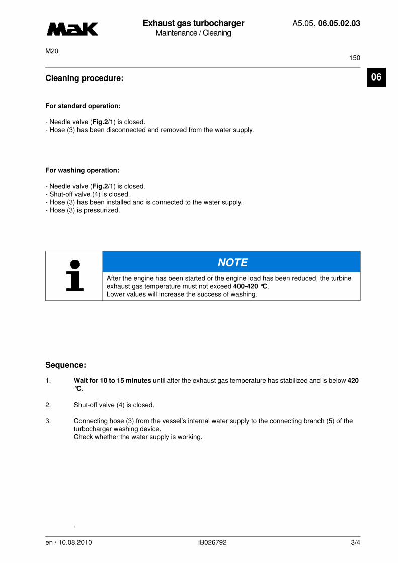
Exhaust gas turbochargerMaintenance / Cleaning
A5.05. 06.05.02.03
150M20
06
Cleaning procedure:For standard operation:
- Needle valve (Fig.2/1) is closed.- Hose (3) has been disconnected and removed from the water supply.
For washing operation:
- Needle valve (Fig.2/1) is closed.- Shut-off valve (4) is closed.- Hose (3) has been installed and is connected to the water supply. - Hose (3) is pressurized.
Sequence:
1. Wait for 10 to 15 minutes until after the exhaust gas temperature has stabilized and is below 420
°C.
2. Shut-off valve (4) is closed.
3. Connecting hose (3) from the vessel’s internal water supply to the connecting branch (5) of the turbocharger washing device.Check whether the water supply is working.
.
NOTE
After the engine has been started or the engine load has been reduced, the turbine exhaust gas temperature must not exceed 400-420 °C.Lower values will increase the success of washing.
en / 10.08.2010 IB026792 3/4

Exhaust gas turbochargerMaintenance / Cleaning
A5.05. 06.05.02.03
150M20
06
4. Open drain valve (Fig.2/4); pressure gauge (8) must indicate a pressure of:p ~ 2 bar
(on-board supply) .
5. Close shut-off valve (4).
6. Open needle valve (1).
7. Open shut-off valve (4) for 30 secs.
8. Check if exhaust gas temperature after turbocharger decreases.
9. The cleaning procedure is complete.
10. Repeat the cleaning procedure 3-4 times.
11. Disconnect the water supply completely, incl. hose (3) from the connecting branch of the (5) turbocharger washing device.
For additional instructions, see User Manual A3.06.06.nn.
CAUTION
After washing, the water
supply must be disconnect-
ed completely; i.e., incl.
hose (3) from the connect-
ing branch (5) to the turbo-
charger washing device.
CAUTION
Avoid getting uncontrolled amounts of water into the turbocharger or the engine. This can cause personal injury and major damage.In order to prevent corrosion on the inside surfaces of the housing, the engine must be run for 30 more minutes at the same load level. Due to increased corrosion risk from wash water residue in the exhaust system, we recommend not performing the washing procedure before longer engine standstill periods.
1
4
8
5
3
2
en / 10.08.2010 IB026792 4/4
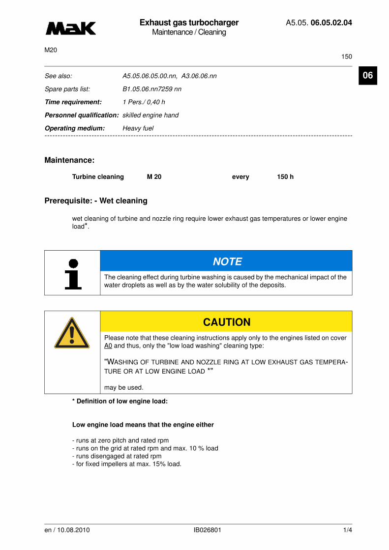
Exhaust gas turbochargerMaintenance / Cleaning
A5.05. 06.05.02.04
150M20
06
-------
See also: A5.05.06.05.00.nn, A3.06.06.nn
Spare parts list: B1.05.06.nn7259 nn
Time requirement: 1 Pers./ 0,40 h
Personnel qualification: skilled engine hand
-------------------------------------------------------------------------------------------------------------------------
Operating medium: Heavy fuel
Maintenance:
Turbine cleaning M 20 every 150 h
Prerequisite: - Wet cleaning
wet cleaning of turbine and nozzle ring require lower exhaust gas temperatures or lower engine load*.
* Definition of low engine load:
Low engine load means that the engine either
- runs at zero pitch and rated rpm- runs on the grid at rated rpm and max. 10 % load- runs disengaged at rated rpm- for fixed impellers at max. 15% load.
NOTE
The cleaning effect during turbine washing is caused by the mechanical impact of the water droplets as well as by the water solubility of the deposits.
CAUTION
Please note that these cleaning instructions apply only to the engines listed on cover A0 and thus, only the "low load washing" cleaning type:
"WASHING OF TURBINE AND NOZZLE RING AT LOW EXHAUST GAS TEMPERA-TURE OR AT LOW ENGINE LOAD *"
may be used.
en / 10.08.2010 IB026801 1/4
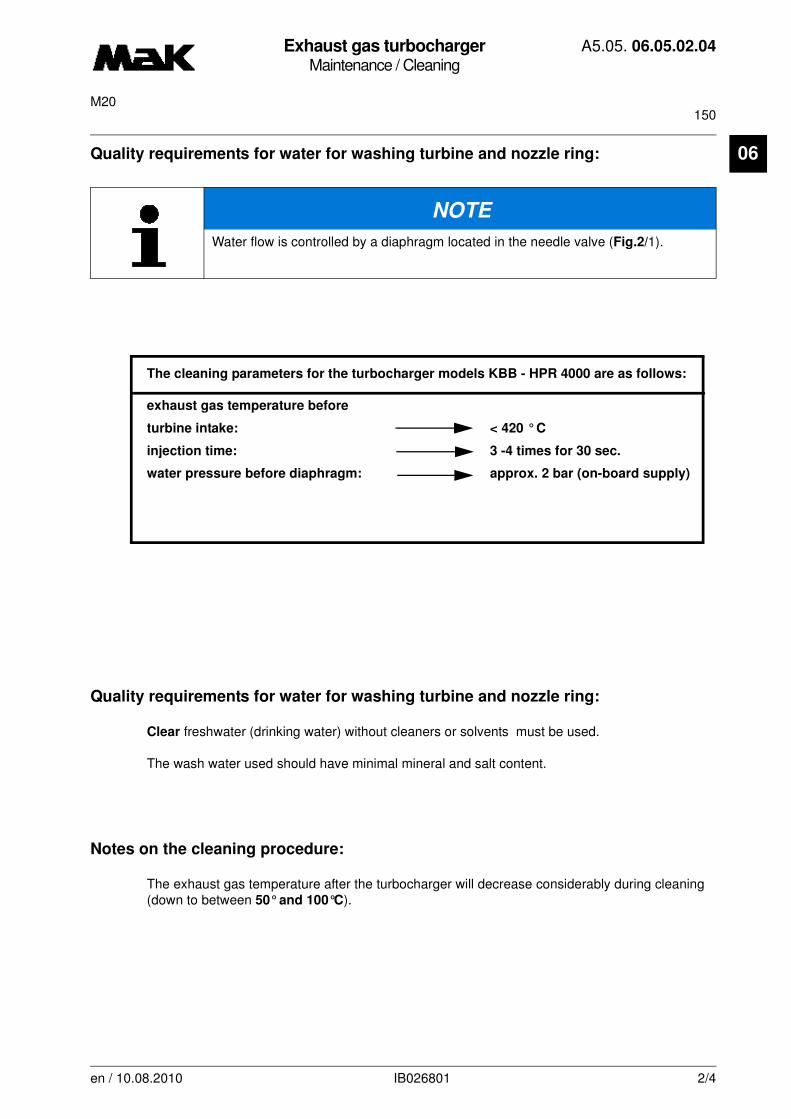
Exhaust gas turbochargerMaintenance / Cleaning
A5.05. 06.05.02.04
150M20
06
Quality requirements for water for washing turbine and nozzle ring:The cleaning parameters for the turbocharger models KBB - HPR 4000 are as follows:
exhaust gas temperature before
turbine intake: < 420 ° C
injection time: 3 -4 times for 30 sec.
water pressure before diaphragm: approx. 2 bar (on-board supply)
Quality requirements for water for washing turbine and nozzle ring:
Clear freshwater (drinking water) without cleaners or solvents must be used.
The wash water used should have minimal mineral and salt content.
Notes on the cleaning procedure:
The exhaust gas temperature after the turbocharger will decrease considerably during cleaning(down to between 50° and 100°C).
NOTE
Water flow is controlled by a diaphragm located in the needle valve (Fig.2/1).
en / 10.08.2010 IB026801 2/4
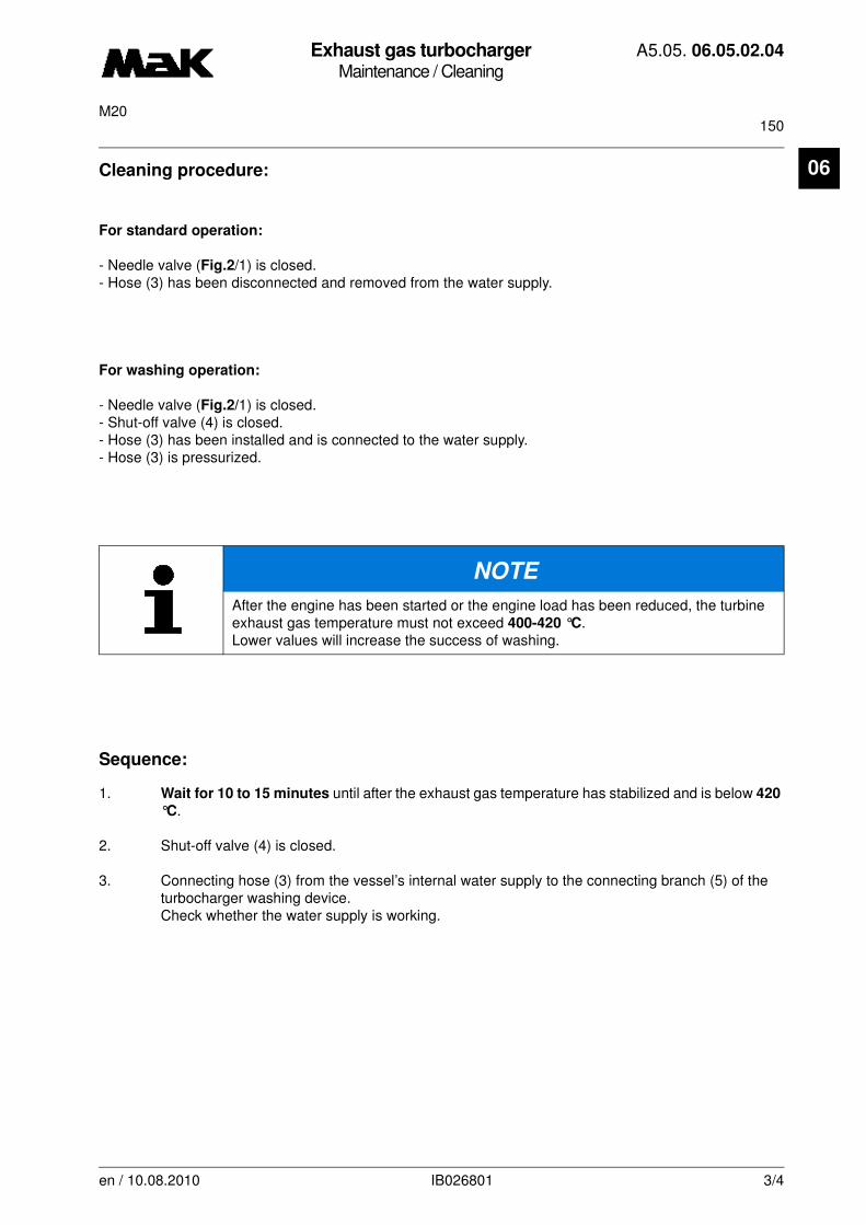
Exhaust gas turbochargerMaintenance / Cleaning
A5.05. 06.05.02.04
150M20
06
Cleaning procedure:For standard operation:
- Needle valve (Fig.2/1) is closed.- Hose (3) has been disconnected and removed from the water supply.
For washing operation:
- Needle valve (Fig.2/1) is closed.- Shut-off valve (4) is closed.- Hose (3) has been installed and is connected to the water supply. - Hose (3) is pressurized.
Sequence:
1. Wait for 10 to 15 minutes until after the exhaust gas temperature has stabilized and is below 420
°C.
2. Shut-off valve (4) is closed.
3. Connecting hose (3) from the vessel’s internal water supply to the connecting branch (5) of the turbocharger washing device.Check whether the water supply is working.
NOTE
After the engine has been started or the engine load has been reduced, the turbine exhaust gas temperature must not exceed 400-420 °C.Lower values will increase the success of washing.
en / 10.08.2010 IB026801 3/4
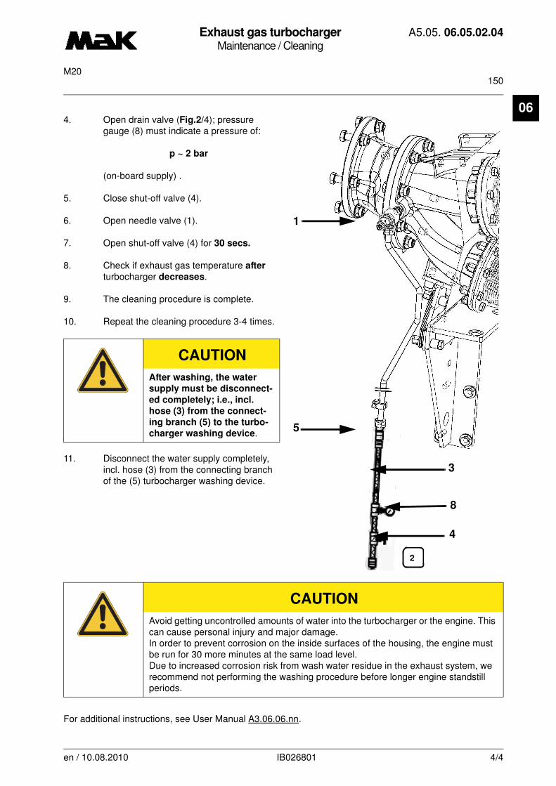
Exhaust gas turbochargerMaintenance / Cleaning
A5.05. 06.05.02.04
150M20
06
4. Open drain valve (Fig.2/4); pressuregauge (8) must indicate a pressure of:
p ~ 2 bar
(on-board supply) .
5. Close shut-off valve (4).
6. Open needle valve (1).
7. Open shut-off valve (4) for 30 secs.
8. Check if exhaust gas temperature after turbocharger decreases.
9. The cleaning procedure is complete.
10. Repeat the cleaning procedure 3-4 times.
11. Disconnect the water supply completely, incl. hose (3) from the connecting branch of the (5) turbocharger washing device.
For additional instructions, see User Manual A3.06.06.nn.
CAUTION
After washing, the water
supply must be disconnect-
ed completely; i.e., incl.
hose (3) from the connect-
ing branch (5) to the turbo-
charger washing device.
CAUTION
Avoid getting uncontrolled amounts of water into the turbocharger or the engine. This can cause personal injury and major damage.In order to prevent corrosion on the inside surfaces of the housing, the engine must be run for 30 more minutes at the same load level. Due to increased corrosion risk from wash water residue in the exhaust system, we recommend not performing the washing procedure before longer engine standstill periods.
1
4
8
5
3
2
en / 10.08.2010 IB026801 4/4
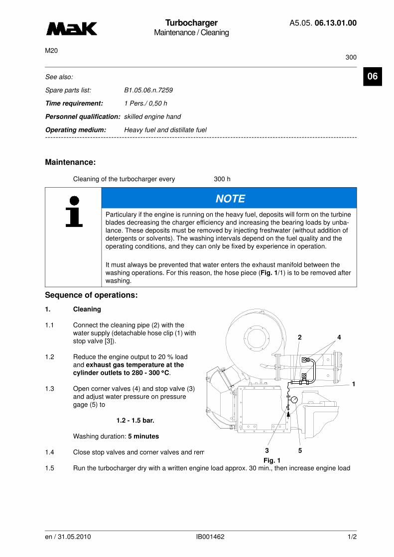
TurbochargerMaintenance / Cleaning
A5.05. 06.13.01.00
300M20
06
-------
See also:
Spare parts list: B1.05.06.n.7259
Time requirement: 1 Pers./ 0,50 h
Personnel qualification: skilled engine hand
-------------------------------------------------------------------------------------------------------------------------
Operating medium: Heavy fuel and distillate fuel
Maintenance:
Cleaning of the turbocharger every 300 h
Sequence of operations:
1. Cleaning
1.1 Connect the cleaning pipe (2) with the water supply (detachable hose clip (1) with stop valve [3]).
1.2 Reduce the engine output to 20 % load and exhaust gas temperature at the
cylinder outlets to 280 - 300 °°°°C.
1.3 Open corner valves (4) and stop valve (3) and adjust water pressure on pressure gage (5) to
1.2 - 1.5 bar.
Washing duration: 5 minutes
1.4 Close stop valves and corner valves and remove hose clip (Fig. 1/1).
1.5 Run the turbocharger dry with a written engine load approx. 30 min., then increase engine load
NOTE
Particulary if the engine is running on the heavy fuel, deposits will form on the turbine blades decreasing the charger efficiency and increasing the bearing loads by unba-lance. These deposits must be removed by injecting freshwater (without addition of detergents or solvents). The washing intervals depend on the fuel quality and the operating conditions, and they can only be fixed by experience in operation.
It must always be prevented that water enters the exhaust manifold between the washing operations. For this reason, the hose piece (Fig. 1/1) is to be removed after washing.
2 4
1
53
Fig. 1
en / 31.05.2010 IB001462 1/2
TurbochargerMaintenance / Cleaning
A5.05. 06.13.01.00
300M20
06
slowly.NOTE
Repeat washing procedure if vibrations and sounds appear at the turbocharger which were previously not present.
en / 31.05.2010 IB001462 2/2
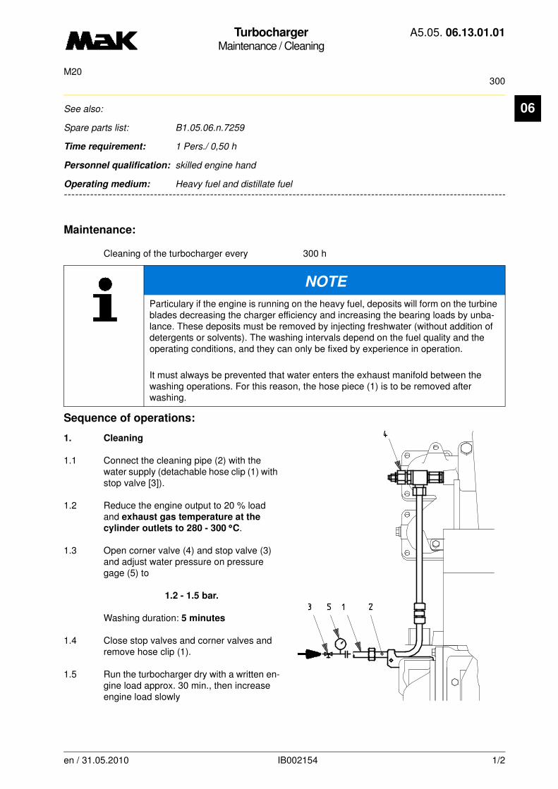
TurbochargerMaintenance / Cleaning
A5.05. 06.13.01.01
300M20
06
-------
See also:
Spare parts list: B1.05.06.n.7259
Time requirement: 1 Pers./ 0,50 h
Personnel qualification: skilled engine hand
-------------------------------------------------------------------------------------------------------------------------
Operating medium: Heavy fuel and distillate fuel
Maintenance:
Cleaning of the turbocharger every 300 h
Sequence of operations:
1. Cleaning
1.1 Connect the cleaning pipe (2) with the water supply (detachable hose clip (1) with stop valve [3]).
1.2 Reduce the engine output to 20 % load and exhaust gas temperature at the
cylinder outlets to 280 - 300 °°°°C.
1.3 Open corner valve (4) and stop valve (3) and adjust water pressure on pressure gage (5) to
1.2 - 1.5 bar.
Washing duration: 5 minutes
1.4 Close stop valves and corner valves and remove hose clip (1).
1.5 Run the turbocharger dry with a written en-gine load approx. 30 min., then increase engine load slowly
NOTE
Particulary if the engine is running on the heavy fuel, deposits will form on the turbine blades decreasing the charger efficiency and increasing the bearing loads by unba-lance. These deposits must be removed by injecting freshwater (without addition of detergents or solvents). The washing intervals depend on the fuel quality and the operating conditions, and they can only be fixed by experience in operation.
It must always be prevented that water enters the exhaust manifold between the washing operations. For this reason, the hose piece (1) is to be removed after washing.
en / 31.05.2010 IB002154 1/2
TurbochargerMaintenance / Cleaning
A5.05. 06.13.01.01
300M20
06
.NOTE
Repeat washing procedure if vibrations and sounds appear at the turbocharger which were previously not present.
en / 31.05.2010 IB002154 2/2
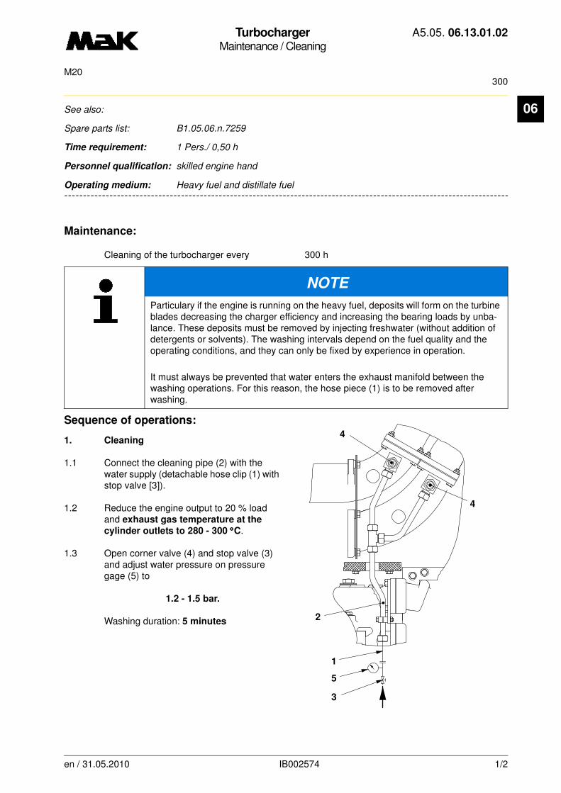
TurbochargerMaintenance / Cleaning
A5.05. 06.13.01.02
300M20
06
-------
See also:
Spare parts list: B1.05.06.n.7259
Time requirement: 1 Pers./ 0,50 h
Personnel qualification: skilled engine hand
-------------------------------------------------------------------------------------------------------------------------
Operating medium: Heavy fuel and distillate fuel
Maintenance:
Cleaning of the turbocharger every 300 h
Sequence of operations:
1. Cleaning
1.1 Connect the cleaning pipe (2) with the water supply (detachable hose clip (1) with stop valve [3]).
1.2 Reduce the engine output to 20 % load and exhaust gas temperature at the
cylinder outlets to 280 - 300 °°°°C.
1.3 Open corner valve (4) and stop valve (3) and adjust water pressure on pressure gage (5) to
1.2 - 1.5 bar.
Washing duration: 5 minutes
NOTE
Particulary if the engine is running on the heavy fuel, deposits will form on the turbine blades decreasing the charger efficiency and increasing the bearing loads by unba-lance. These deposits must be removed by injecting freshwater (without addition of detergents or solvents). The washing intervals depend on the fuel quality and the operating conditions, and they can only be fixed by experience in operation.
It must always be prevented that water enters the exhaust manifold between the washing operations. For this reason, the hose piece (1) is to be removed after washing.
4
5
3
1
2
4
en / 31.05.2010 IB002574 1/2
TurbochargerMaintenance / Cleaning
A5.05. 06.13.01.02
300M20
06
1.4 Close stop valves and corner valves and remove hose clip (1).
1.5 Run the turbocharger dry with a written engine load approx. 30 min., then increase engine load slowly.
NOTE
Repeat washing procedure if vibrations and sounds appear at the turbocharger which were previously not present.
en / 31.05.2010 IB002574 2/2

TurbochargerMaintenance / Cleaning
A5.05. 06.13.01.03
300M20
06
-------
See also:
Spare parts list: B1.05.06.n.7259
Time requirement: 1 Pers./ 0,50 h
Personnel qualification: skilled engine hand
-------------------------------------------------------------------------------------------------------------------------
Operating medium: Heavy fuel and distillate fuel
Maintenance:
Cleaning of the turbocharger every 300 h
Sequence of operations:
1. Cleaning
1.1 Connect the cleaning pipe (2) with the water supply (detachable hose clip (1) with stop valve [3]).
1.2 Reduce the engine output to 20 % load and exhaust gas temperature at the
cylinder outlets to 280 - 300 °°°°C.
1.3 Open corner valve (4) and stop valve (3) and adjust water pressure on pressure gage (5) to
1.2 - 1.5 bar.
Washing duration: 5 minutes
1.4 Close stop valves and corner valves and remove hose clip (1).
1.5 Run the turbocharger dry with a written engine load approx. 30 min., then increase engine load
NOTE
Particulary if the engine is running on the heavy fuel, deposits will form on the turbine blades decreasing the charger efficiency and increasing the bearing loads by unba-lance. These deposits must be removed by injecting freshwater (without addition of detergents or solvents). The washing intervals depend on the fuel quality and the operating conditions, and they can only be fixed by experience in operation.
It must always be prevented that water enters the exhaust manifold between the wa-shing operations. For this reason, the hose piece (1) is to be removed after washing.
2
4
5
1
3
en / 31.05.2010 IB003041 1/2

TurbochargerMaintenance / Cleaning
A5.05. 06.13.01.03
300M20
06
slowly.NOTE
Repeat washing procedure if vibrations and sounds appear at the turbocharger which were previously not present.
en / 31.05.2010 IB003041 2/2
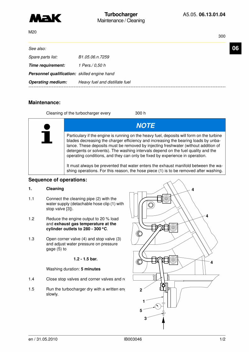
TurbochargerMaintenance / Cleaning
A5.05. 06.13.01.04
300M20
06
-------
See also:
Spare parts list: B1.05.06.n.7259
Time requirement: 1 Pers./ 0,50 h
Personnel qualification: skilled engine hand
-------------------------------------------------------------------------------------------------------------------------
Operating medium: Heavy fuel and distillate fuel
Maintenance:
Cleaning of the turbocharger every 300 h
Sequence of operations:
1. Cleaning
1.1 Connect the cleaning pipe (2) with the water supply (detachable hose clip (1) with stop valve [3]).
1.2 Reduce the engine output to 20 % load and exhaust gas temperature at the
cylinder outlets to 280 - 300 °°°°C.
1.3 Open corner valve (4) and stop valve (3) and adjust water pressure on pressure gage (5) to
1.2 - 1.5 bar.
Washing duration: 5 minutes
1.4 Close stop valves and corner valves and remove hose clip (1).
1.5 Run the turbocharger dry with a written engine load approx. 30 min., then increase engine load slowly.
NOTE
Particulary if the engine is running on the heavy fuel, deposits will form on the turbine blades decreasing the charger efficiency and increasing the bearing loads by unba-lance. These deposits must be removed by injecting freshwater (without addition of detergents or solvents). The washing intervals depend on the fuel quality and the operating conditions, and they can only be fixed by experience in operation.
It must always be prevented that water enters the exhaust manifold between the wa-shing operations. For this reason, the hose piece (1) is to be removed after washing.
4
4
4
1
2
3
5
en / 31.05.2010 IB003046 1/2

TurbochargerMaintenance / Cleaning
A5.05. 06.13.01.04
300M20
06
NOTE
Repeat washing procedure if vibrations and sounds appear at the turbocharger which were previously not present.
en / 31.05.2010 IB003046 2/2

TurbochargerMaintenance / Cleaning
A5.05. 06.13.01.05
300M20
06
-------
See also:
Spare parts list: B1.05.06.n.7259
Time requirement: 1 Pers./ 0,50 h
Personnel qualification: skilled engine hand
-------------------------------------------------------------------------------------------------------------------------
Operating medium: Heavy fuel and distillate fuel
Maintenance:
Cleaning of the turbocharger every 300 h
Sequence of operations:
1. Cleaning
1.1 Connect the cleaning pipe (2) with the water supply (detachable hose clip (1) with stop valve [3]).
1.2 Reduce the engine output to 20 % load and exhaust gas temperature at the
cylinder outlets to 280 - 300 °°°°C.
1.3 Open corner valve (4) and stop valve (3) and adjust water pressure on pressure gage (5) to
1.2 - 1.5 bar.
Washing duration: 5 minutes
1.4 Close stop valves and corner valves and remove hose clip (1).
1.5 Run the turbocharger dry with a written engine load approx. 30 min., then increase engine load slowly.
NOTE
Particulary if the engine is running on the heavy fuel, deposits will form on the turbine blades decreasing the charger efficiency and increasing the bearing loads by unba-lance. These deposits must be removed by injecting freshwater (without addition of detergents or solvents). The washing intervals depend on the fuel quality and the operating conditions, and they can only be fixed by experience in operation.
It must always be prevented that water enters the exhaust manifold between the wa-shing operations. For this reason, the hose piece (1) is to be removed after washing.
4
2
4
4
3
5
1
en / 31.05.2010 IB003054 1/2
TurbochargerMaintenance / Cleaning
A5.05. 06.13.01.05
300M20
06
NOTE
Repeat washing procedure if vibrations and sounds appear at the turbocharger which were previously not present.
en / 31.05.2010 IB003054 2/2

Exhaust gas turbochargerMaintenance / Cleaning
A5.05. 06.13.01.06
300M20
06
-------
See also:
Spare parts list: B1.05.06.n.7259
Time requirement: 1 Pers./ 0,50 h
Personnel qualification: skilled engine hand
-------------------------------------------------------------------------------------------------------------------------
Operating medium: Heavy fuel and distillate fuel
Maintenance:
Cleaning of the turbocharger every 300 h
Sequence of operations:
1. Cleaning
1.1 Connect the cleaning pipe (2) with the water supply (detachable hose clip (1) with stop valve [3]).
1.2 Open drain valve (Fig.2/1)öffnen.
1.3 Reduce engine output to 20 %, exhaust gas temperature after cylinder
280 - 300 °°°°C.
NOTE
Particularly if the engine is running on heavy fuel, deposits will settle down on the tur-bine blades decreasing the charger efficiency and increasing the bearing loads by unbalance. These deposits must be removed by injecting fresh water (without additi-on of detergents or solvents). The washing intervals depend on the fuel quality and the operating conditions, and they can only be fixed by experience in operation.
It must be absolutely prevented that water enters the exhaust manifold between the washing operations. For this reason, the hose piece (Fig.1/1) is to be removed after washing.
DANGER
Attention, danger of burning!The waste water runs off with a temperature of > 70 °°°°C.
2
4
4
4
1
5
3
1
en / 31.05.2010 IB004495 1/2

Exhaust gas turbochargerMaintenance / Cleaning
A5.05. 06.13.01.06
300M20
06
1.4 Open corner valves (Fig.1/4) and stop valve (3) and set water pressure on pressure gauge (5) to1,2 - 1,5 bar
Duration of washing: 5 minutes
1.5 Close stop (Fig.1/3) and corner valves (4) and remove hose clip (1).
1.6 If no further water runs out of the drain pipe (Fig.2/2), close the drain valve (1).
1.7 Let the exhaust gas turbocharger dry for about 30 minutes at the specified engine load, then slowly increase the engine load.
CAUTION
Check drain valve (Fig. 2/4) and pipe (2) during the washing process permanently for free passage. Clogging by deposits involves the risk that water runs bakc into the engine through the exhaust gas pipe.In case of clogging pierce the drain valve with a wire.
NOTE
In case of previously non-existent vibrations and noises at the exhaust gas turbocharger, repeat the washing process.
2
1
2
en / 31.05.2010 IB004495 2/2

AbgasturboladerMaintenance / Cleaning
A5.05. 06.13.01.07
300M20
06
-------
See also:
Spare parts list: B1.05.06.n.7259
Time requirement: 1 Pers./ 0,50 h
Personnel qualification: skilled engine hand
-------------------------------------------------------------------------------------------------------------------------
Operating medium: Heavy fuel and distillate fuel
Maintenance:
Cleaning of the turbocharger every 300 h
Sequence of operations:
1. Cleaning
1.1 Connect the cleaning pipe (2) with the water supply (detachable hose clip (1) with stop valve [3]).
1.2 Open drain valve (Fig.2/1)öffnen.
1.3 Reduce engine output to 20 %, exhaust gas temperature after cylinder
280 - 300 °°°°C.
NOTE
Particularly if the engine is running on heavy fuel, deposits will settle down on the tur-bine blades decreasing the charger efficiency and increasing the bearing loads by unbalance. These deposits must be removed by injecting fresh water (without additi-on of detergents or solvents). The washing intervals depend on the fuel quality and the operating conditions, and they can only be fixed by experience in operation.
It must be absolutely prevented that water enters the exhaust manifold between the washing operations. For this reason, the hose piece (Fig.1/1) is to be removed after washing.
DANGER
Attention, danger of burning!The waste water runs off with a temperature of > 70 °°°°C.
4
4
4
2
1
5
3
1
en / 31.05.2010 IB004503 1/2
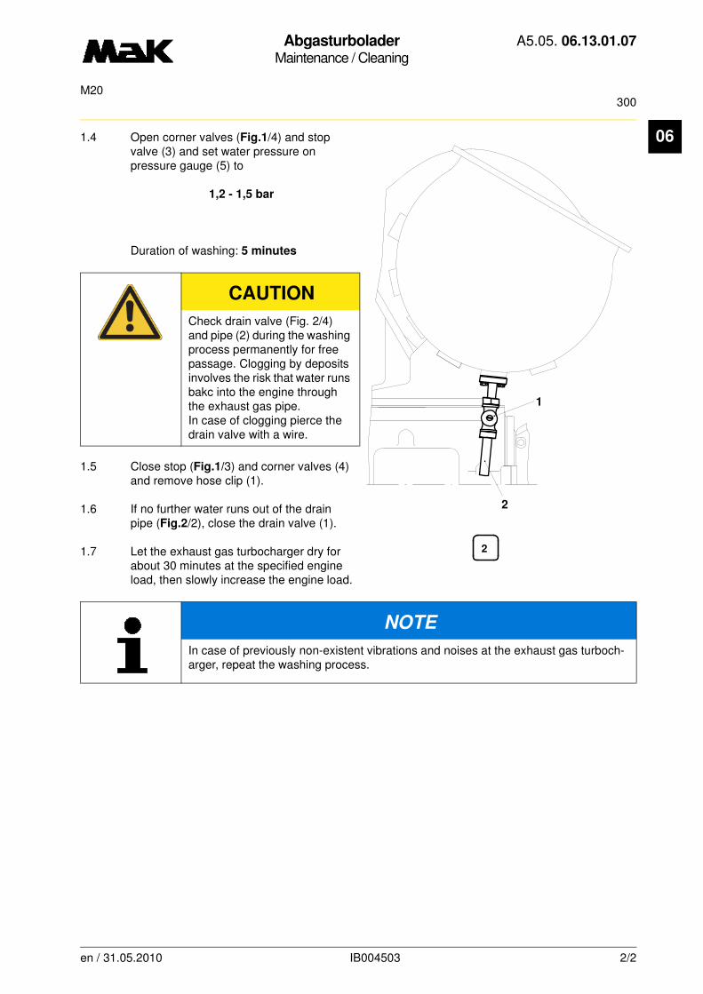
AbgasturboladerMaintenance / Cleaning
A5.05. 06.13.01.07
300M20
06
1.4 Open corner valves (Fig.1/4) and stop valve (3) and set water pressure on pressure gauge (5) to1,2 - 1,5 bar
Duration of washing: 5 minutes
1.5 Close stop (Fig.1/3) and corner valves (4) and remove hose clip (1).
1.6 If no further water runs out of the drain pipe (Fig.2/2), close the drain valve (1).
1.7 Let the exhaust gas turbocharger dry for about 30 minutes at the specified engine load, then slowly increase the engine load.
CAUTION
Check drain valve (Fig. 2/4) and pipe (2) during the washing process permanently for free passage. Clogging by deposits involves the risk that water runs bakc into the engine through the exhaust gas pipe.In case of clogging pierce the drain valve with a wire.
NOTE
In case of previously non-existent vibrations and noises at the exhaust gas turboch-arger, repeat the washing process.
1
2
2
en / 31.05.2010 IB004503 2/2

TurbochargerMaintenance / Cleaning
A5.05. 06.13.01.08
300M20
06
-------
See also:
Spare parts list: B1.05.06.n.7259
Time requirement: 1 Pers./ 0,50 h
Personnel qualification: skilled engine hand
-------------------------------------------------------------------------------------------------------------------------
Operating medium: Heavy fuel and distillate fuel
Maintenance:
Cleaning of the turbocharger every 300 h
Sequence of operations:
1. Cleaning
1.1 Connect the cleaning pipe (2) with the water supply (detachable hose clip (1) with stop valve [3]).
1.2 Open drain valve (Fig.2/1)öffnen.
1.3 Reduce engine output to 20 %, exhaust gas temperature after cylinder
280 - 300 °°°°C.
NOTE
Particularly if the engine is running on heavy fuel, deposits will settle down on the tur-bine blades decreasing the charger efficiency and increasing the bearing loads by unbalance. These deposits must be removed by injecting fresh water (without additi-on of detergents or solvents). The washing intervals depend on the fuel quality and the operating conditions, and they can only be fixed by experience in operation.
It must be absolutely prevented that water enters the exhaust manifold between the washing operations. For this reason, the hose piece (Fig.1/1) is to be removed after washing.
DANGER
Attention, danger of burning!The waste water runs off with a temperature of > 70 °°°°C. 2
3
1
5
4
1
en / 31.05.2010 IB004510 1/2
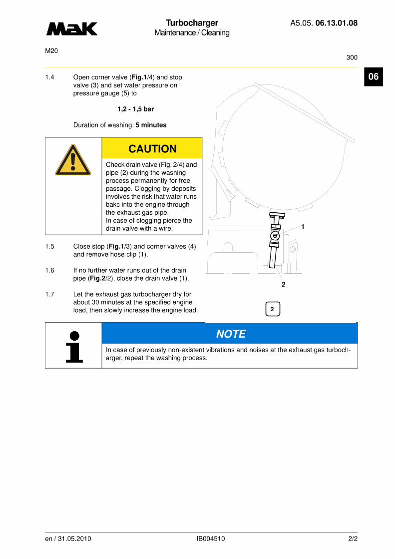
TurbochargerMaintenance / Cleaning
A5.05. 06.13.01.08
300M20
06
1.4 Open corner valve (Fig.1/4) and stop valve (3) and set water pressure on pressure gauge (5) to1,2 - 1,5 bar
Duration of washing: 5 minutes
1.5 Close stop (Fig.1/3) and corner valves (4) and remove hose clip (1).
1.6 If no further water runs out of the drain pipe (Fig.2/2), close the drain valve (1).
1.7 Let the exhaust gas turbocharger dry for about 30 minutes at the specified engine load, then slowly increase the engine load.
CAUTION
Check drain valve (Fig. 2/4) and pipe (2) during the washing process permanently for free passage. Clogging by deposits involves the risk that water runs bakc into the engine through the exhaust gas pipe.In case of clogging pierce the drain valve with a wire.
NOTE
In case of previously non-existent vibrations and noises at the exhaust gas turboch-arger, repeat the washing process.
2
1
2
en / 31.05.2010 IB004510 2/2
Exhaust gas turbocharger - HPR 5000 -Repair / Replacement
A5.05. 06.13.02.11
12000, 24000, 48000, 250, 1000M20
06
-------
See also: A3.06.06.nn
Spare parts list: B1.05.06.nn725n nn
Time requirement: 1 Pers./ 0,40 h
Personnel qualification: skilled engine hand
-------------------------------------------------------------------------------------------------------------------------
Operating medium: Heavy fuel
NOTE
The exhaust gas turbocharger must generally be maintained according to the main-tenance instructions in Book C or the Operating Instructions.
Below is a list of maintenance tasks that must be performed using the work interval schedule according to the operating instructions in Book C after the number of oper-ating hours listed.
The operating hours listed are guidelines that may need to be shortened or length-ened depending on the operating conditions, as well as for adapting to engine main-tenance intervals.
For "Washing the Turbocharger", the work processes are described in work cards (A5.05.06.05.01.nn) & (A5.05.06.05.02.nn) .
Instructions for emergency engine operation with a defective turbocharger see User Manual A3.12.01.nn.
en / 31.05.2010 IB025473 1/2
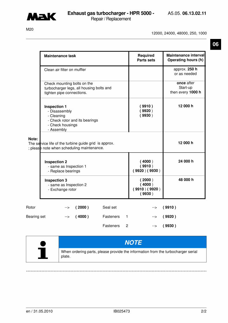
Exhaust gas turbocharger - HPR 5000 -Repair / Replacement
A5.05. 06.13.02.11
12000, 24000, 48000, 250, 1000M20
06
-------
Rotor --> ( 2000 ) Seal set --> ( 9910 )
Bearing set --> ( 4000 ) Fasteners 1 --> ( 9920 )
Fasteners 2 --> ( 9930 )
-------------------------------------------------------------------------------------------------------------------------
NOTE
When ordering parts, please provide the information from the turbocharger serial plate.
Maintenance task Required Maintenance interval
Parts sets Operating hours (h)
Clean air filter on muffler approx. 250 h
or as needed
Check mounting bolts on the once after
turbocharger legs, all housing bolts and Start-up
tighten pipe connections. then every 1000 h
Inspection 1 ( 9910 ) 12 000 h
- Disassembly ( 9920 )
- Cleaning ( 9930 )
- Check rotor and its bearings
- Check housings
- Assembly
Note:
The service life of the turbine guide grid is approx. 12 000 h
; please note when scheduling maintenance.
Inspection 2 ( 4000 ) 24 000 h
- same as Inspection 1 ( 9910 )
- Replace bearings ( 9920 ) ( 9930 )
Inspection 3 ( 2000 ) 48 000 h
- same as Inspection 2 ( 4000 )
- Exchange rotor ( 9910 ) ( 9920 )
( 9930 )
en / 31.05.2010 IB025473 2/2
Exhaust gas turbocharger - HPR 4000 -Repair / Replacement
A5.05. 06.13.02.12
12000, 24000, 48000, 250, 1000M20
06
-------
See also: A3.06.06.nn
Spare parts list: B1.05.06.nn725n nn
Time requirement: 1 Pers./ 0,40 h
Personnel qualification: skilled engine hand
-------------------------------------------------------------------------------------------------------------------------
Operating medium: Heavy fuel
NOTE
The exhaust gas turbocharger must generally be maintained according to the main-tenance instructions in Book C or the Operating Instructions.
Below is a list of maintenance tasks that must be performed using the work interval schedule according to the operating instructions in Book C after the number of oper-ating hours listed.
The operating hours listed are guidelines that may need to be shortened or length-ened depending on the operating conditions, as well as for adapting to engine main-tenance intervals.
For "Washing the Turbocharger", the work processes are described in work cards (A5.05.06.05.01.nn) & (A5.05.06.05.02.nn) .
Instructions for emergency engine operation with a defective turbocharger see User Manual A3.12.01.nn.
en / 31.05.2010 IB025572 1/2

Exhaust gas turbocharger - HPR 4000 -Repair / Replacement
A5.05. 06.13.02.12
12000, 24000, 48000, 250, 1000M20
06
Rotor --> ( 2000 ) Seal set --> ( 9910 )
Bearing set --> ( 4000 ) Fasteners 1 --> ( 9920 )
Fasteners 2 --> ( 9930 )
NOTE
When ordering parts, please provide the information from the turbocharger serial plate.
Maintenance task Required Maintenance interval
Parts sets Operating hours (h)
Clean air filter on muffler approx. 250 h
or as needed
Check mounting bolts on the once after
turbocharger legs, all housing bolts and Start-up
tighten pipe connections. then every 1000 h
Inspection 1 ( 9910 ) 12 000 h
- Disassembly ( 9920 )
- Cleaning ( 9930 )
- Check rotor and its bearings
- Check housings
- Assembly
Note:
The service life of the turbine guide grid is approx. 12 000 h
; please note when scheduling maintenance.
Inspection 2 ( 4000 ) 24 000 h
- same as Inspection 1 ( 9910 )
- Replace bearings ( 9920 ) ( 9930 )
Inspection 3 ( 2000 ) 48 000 h
- same as Inspection 2 ( 4000 )
- Exchange rotor ( 9910 ) ( 9920 )
( 9930 )
en / 31.05.2010 IB025572 2/2

Injection PumpRepair / Disassembly and reassembly
A5.05. 07.02.01.00
M20
07
-------
See also:
Spare parts list: B1.05.07.2.3580
Time requirement: 1 Pers./ 1,00 h
Personnel qualification: skilled engine hand
-------------------------------------------------------------------------------------------------------------------------
Operating medium: Heavy fuel and distillate fuel
Tools:
Torque wrench 40 - 180 Nm W1 * 1.9454-40
* not available as figure
Auxiliary material:
Molykote paste “G-Rapid Plus” **
** or a product of equal standard
Sequence of operations:
1. Disassembly
1.1 Empty fuel system (drain cock at counter-coupling side over fuel double filter).
1.2 Disassemble lube oil lines (Fig. 1/1) at the injection pump.
Fig. 1
1
2
X
3
en / 31.05.2010 IB001371 1/3
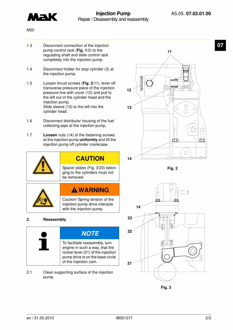
Injection PumpRepair / Disassembly and reassembly
A5.05. 07.02.01.00
M20
07
1.3 Disconnect connection of the injection pump control rack (Fig. 1/2) to the regulating shaft and slide control rack completely into the injection pump.1.4 Disconnect holder for stop cylinder (3) at the injection pump.
1.5 Loosen thrust screws (Fig. 2/11), lever off transverse pressure piece of the injection pressure line with cover (12) and pull to the left out of the cylinder head and the injection pump.Slide sleeve (13) to the left into the cylinder head.
1.6 Disconnect distributor housing of the fuel collecting pipe at the injection pump.
1.7 Loosen nuts (14) of the fastening screws at the injection pump uniformly and lift the injection pump off cylinder crankcase.
2. Reassembly
2.1 Clean supporting surface of the injection pump.
CAUTION
Spacer plates (Fig. 3/23) belon-ging to the cylinders must not be removed.
WARNING
Caution! Spring tension of the injection pump drive interacts with the injection pump.
NOTE
To facilitate reassembly, turn engine in such a way, that the rocker lever (21) of the injection pump drive is on the base circle of the injection cam.
Fig. 2
11
12
13
14
Fig. 3
14
23
22
21
en / 31.05.2010 IB001371 2/3
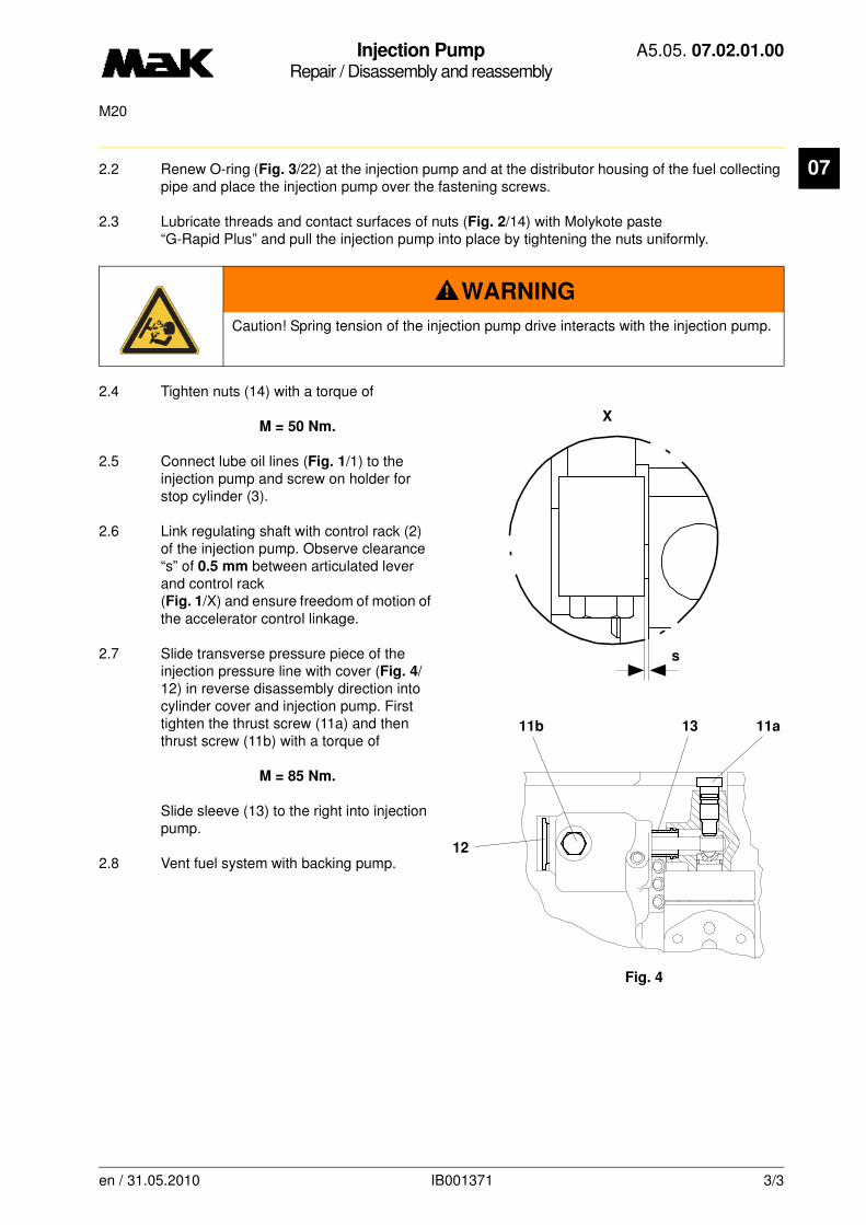
Injection PumpRepair / Disassembly and reassembly
A5.05. 07.02.01.00
M20
07
2.2 Renew O-ring (Fig. 3/22) at the injection pump and at the distributor housing of the fuel collecting pipe and place the injection pump over the fastening screws.2.3 Lubricate threads and contact surfaces of nuts (Fig. 2/14) with Molykote paste “G-Rapid Plus” and pull the injection pump into place by tightening the nuts uniformly.
2.4 Tighten nuts (14) with a torque of
M = 50 Nm.
2.5 Connect lube oil lines (Fig. 1/1) to the injection pump and screw on holder for stop cylinder (3).
2.6 Link regulating shaft with control rack (2) of the injection pump. Observe clearance “s” of 0.5 mm between articulated lever and control rack (Fig. 1/X) and ensure freedom of motion of the accelerator control linkage.
2.7 Slide transverse pressure piece of the injection pressure line with cover (Fig. 4/12) in reverse disassembly direction into cylinder cover and injection pump. First tighten the thrust screw (11a) and then thrust screw (11b) with a torque of
M = 85 Nm.
Slide sleeve (13) to the right into injection pump.
2.8 Vent fuel system with backing pump.
WARNING
Caution! Spring tension of the injection pump drive interacts with the injection pump.
X
s
1311b 11a
12
Fig. 4
en / 31.05.2010 IB001371 3/3

Injection PumpRepair / Disassembly and reassembly
A5.05. 07.02.01.01
M20
07
-------
See also: A5.05.07.15.01.nn
Spare parts list: B1.05.04.2.3580
Time requirement: 1 Pers./ 1,00 h
Personnel qualification: skilled engine hand
-------------------------------------------------------------------------------------------------------------------------
Operating medium: Heavy fuel and distillate fuel
Tools:
Torque wrench 40 - 180 Nm W1 * 1.9454-40
* not available as figure
Auxiliary material:
soft green soap**Molykote paste “G-Rapid Plus” ** ** or a product of equal standard
Sequence of operations:
1. Disassembly
1.1 Empty fuel system (drain cock at counter-coupling side over fuel double filter).
1.2 Disassemble lube oil lines (Fig. 1/1) at the injection pump.
3
2
X
11
en / 30.09.2010 IB003956 1/3

Injection PumpRepair / Disassembly and reassembly
A5.05. 07.02.01.01
M20
07
1.3 Disconnect connection of the injection pump control rack (Fig. 1/2) to the regulating shaft and slide control rack completely into the injection pump.1.4 Disconnect holder for stop cylinder (3) at the injection pump.
1.5 Loosen thrust screws (Fig. 2/11), lever off transverse pressure piece of the injection pressure line with cover (12) and pull to the left out of the cylinder head and the injection pump.Slide sleeve (13) to the left into the cylinder head.
1.6 Loosen the fuel manifold and collector (07.15.01.nn).
1.7 Loosen nuts (14) of the fastening screws at the injection pump uniformly and lift the injection pump off cylinder crankcase.
2. Reassembly
2.1 Clean supporting surface of the injection pump.
CAUTION
Spacer plates (Fig. 3/23) be-longing to the cylinders must not be removed.
WARNING
Caution! Spring tension of the injection pump drive interacts with the injection pump.
NOTE
To facilitate reassembly, turn engine in such a way, that the rocker lever (21) of the injec-tion pump drive is on the base circle of the injection cam.
11
13
11
14
12
2
23
22
14
24
21
3
en / 30.09.2010 IB003956 2/3
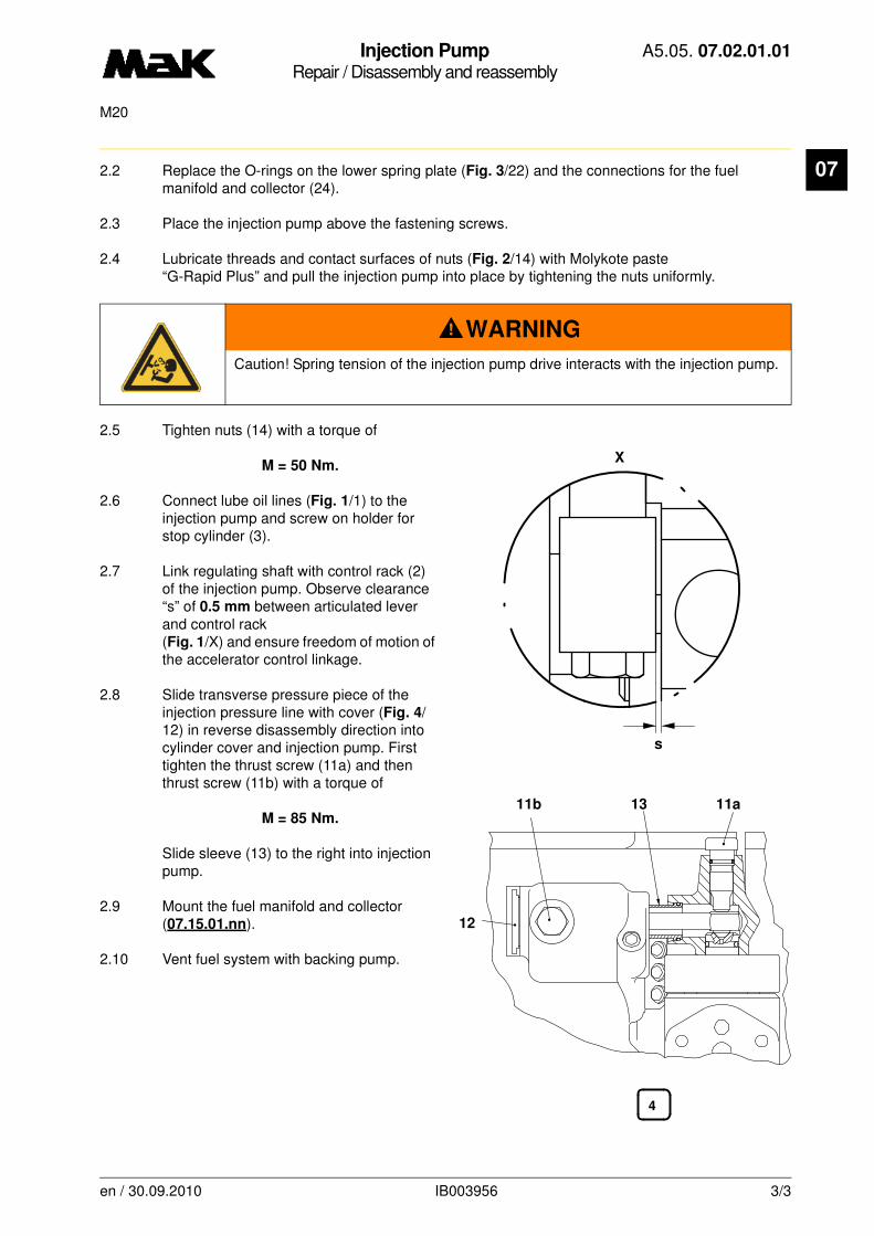
Injection PumpRepair / Disassembly and reassembly
A5.05. 07.02.01.01
M20
07
2.2 Replace the O-rings on the lower spring plate (Fig. 3/22) and the connections for the fuel manifold and collector (24).2.3 Place the injection pump above the fastening screws.
2.4 Lubricate threads and contact surfaces of nuts (Fig. 2/14) with Molykote paste “G-Rapid Plus” and pull the injection pump into place by tightening the nuts uniformly.
2.5 Tighten nuts (14) with a torque of
M = 50 Nm.
2.6 Connect lube oil lines (Fig. 1/1) to the injection pump and screw on holder for stop cylinder (3).
2.7 Link regulating shaft with control rack (2) of the injection pump. Observe clearance “s” of 0.5 mm between articulated lever and control rack (Fig. 1/X) and ensure freedom of motion of the accelerator control linkage.
2.8 Slide transverse pressure piece of the injection pressure line with cover (Fig. 4/12) in reverse disassembly direction into cylinder cover and injection pump. First tighten the thrust screw (11a) and then thrust screw (11b) with a torque of
M = 85 Nm.
Slide sleeve (13) to the right into injection pump.
2.9 Mount the fuel manifold and collector (07.15.01.nn).
2.10 Vent fuel system with backing pump.
WARNING
Caution! Spring tension of the injection pump drive interacts with the injection pump.
X
s
4
13 11a11b
12
en / 30.09.2010 IB003956 3/3

Injection PumpRepair / Disassembly and reassembly
A5.05. 07.02.01.02
M20
07
-------
See also: A5.05.07.15.01.nn
Spare parts list: B1.05.04.2.3580
Time requirement: 1 Pers./ 1,00 h
Personnel qualification: skilled engine hand
-------------------------------------------------------------------------------------------------------------------------
Operating medium: Heavy fuel and distillate fuel
Tools:
Torque wrench 40 - 180 Nm W1 * 1.9454-40
* not available as figure
Auxiliary material:
soft green soap**Molykote paste “G-Rapid Plus” ** ** or a product of equal standard
Sequence of operations:
1. Disassembly
1.1 Empty fuel system, drain cock (Fig. 5/30) .
1.2 Disassemble lube oil lines (Fig. 1/1) at the injection pump.
1
2
3
25
en / 31.05.2010 IB026455 1/3
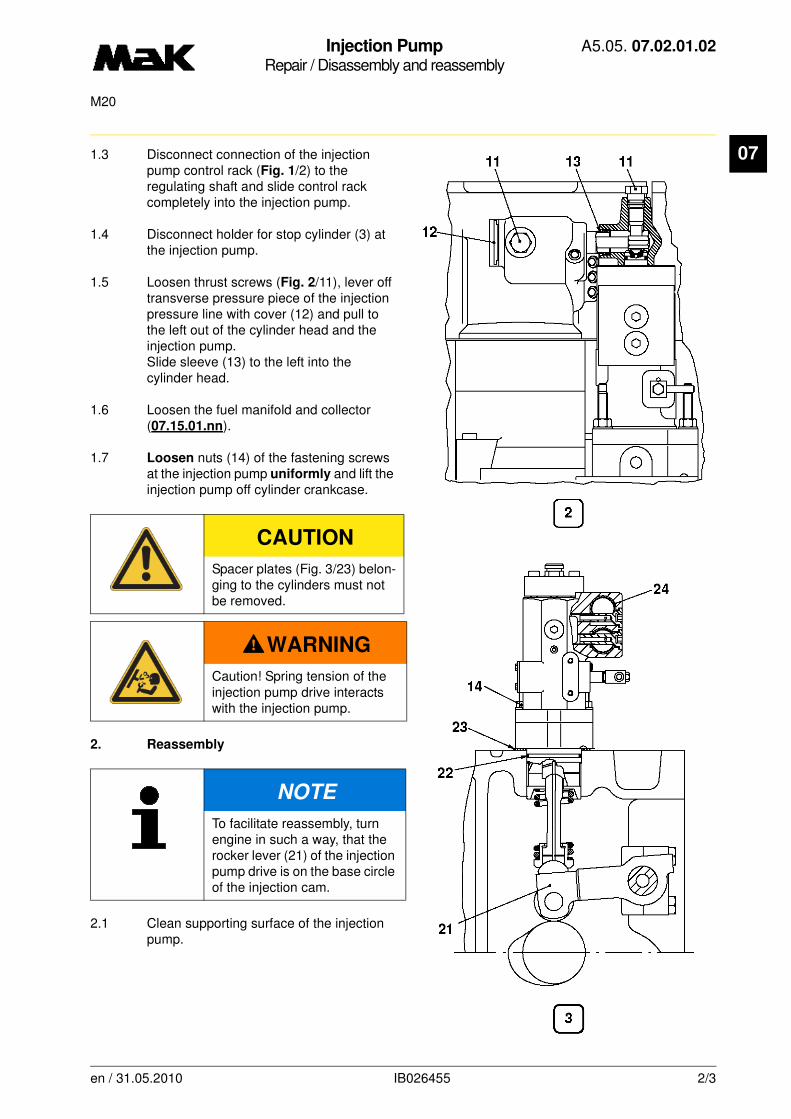
Injection PumpRepair / Disassembly and reassembly
A5.05. 07.02.01.02
M20
07
1.3 Disconnect connection of the injection pump control rack (Fig. 1/2) to the regulating shaft and slide control rack completely into the injection pump.1.4 Disconnect holder for stop cylinder (3) at the injection pump.
1.5 Loosen thrust screws (Fig. 2/11), lever off transverse pressure piece of the injection pressure line with cover (12) and pull to the left out of the cylinder head and the injection pump.Slide sleeve (13) to the left into the cylinder head.
1.6 Loosen the fuel manifold and collector (07.15.01.nn).
1.7 Loosen nuts (14) of the fastening screws at the injection pump uniformly and lift the injection pump off cylinder crankcase.
2. Reassembly
2.1 Clean supporting surface of the injection pump.
CAUTION
Spacer plates (Fig. 3/23) belon-ging to the cylinders must not be removed.
WARNING
Caution! Spring tension of the injection pump drive interacts with the injection pump.
NOTE
To facilitate reassembly, turn engine in such a way, that the rocker lever (21) of the injection pump drive is on the base circle of the injection cam.
en / 31.05.2010 IB026455 2/3
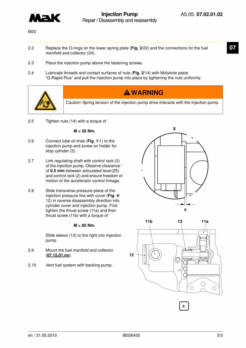
Injection PumpRepair / Disassembly and reassembly
A5.05. 07.02.01.02
M20
07
2.2 Replace the O-rings on the lower spring plate (Fig. 3/22) and the connections for the fuel manifold and collector (24).2.3 Place the injection pump above the fastening screws.
2.4 Lubricate threads and contact surfaces of nuts (Fig. 2/14) with Molykote paste “G-Rapid Plus” and pull the injection pump into place by tightening the nuts uniformly.
2.5 Tighten nuts (14) with a torque of
M = 50 Nm.
2.6 Connect lube oil lines (Fig. 1/1) to the injection pump and screw on holder for stop cylinder (3).
2.7 Link regulating shaft with control rack (2) of the injection pump. Observe clearance “ of 0.5 mm between articulated lever(25) and control rack (2) and ensure freedom of motion of the accelerator control linkage.
2.8 Slide transverse pressure piece of the injection pressure line with cover (Fig. 4/12) in reverse disassembly direction into cylinder cover and injection pump. First tighten the thrust screw (11a) and then thrust screw (11b) with a torque of
M = 85 Nm.
Slide sleeve (13) to the right into injection pump.
2.9 Mount the fuel manifold and collector (07.15.01.nn).
2.10 Vent fuel system with backing pump.
WARNING
Caution! Spring tension of the injection pump drive interacts with the injection pump.
X
s
4
13 11a11b
12
en / 31.05.2010 IB026455 3/3

Injection PumpMaintenance / Disassembly and reassembly
A5.05. 07.03.01.00
15000, 7500M20
07
-------
See also:
Spare parts list: B1.05.07.2.3597
Time requirement: 1 Pers./ 1,00 h
Personnel qualification: skilled engine hand
-------------------------------------------------------------------------------------------------------------------------
Operating medium: Heavy fuel and distillate fuel
Maintenance:
Disassemble injection pump if required, clean all parts and replace if necessary. Observe note!
Tools:
Torque wrench 20 - 90 Nm 1/2" W1* 1.9454-20
* not available as figure
Auxiliary material:
Molykote paste “G-Rapid Plus” *Vaseline *
** or a product of equal standard
Sequence of operations: (Fig. 1)
1. Disassembly
1.1 Clean the outside of the injection pump.
1.2 Remove and check impact screws (Fig. 1/1 and 2).
1.3 Clamp injection pump upwards with injection pump bottom part (3).
NOTE
All parts of the injection pump are manufactured with utmost precision in special workshops. This is the only guarantee for proper function. When repairing a pump, it is to be ensured that the various components of the pump, e.g. control sleeve, con-trol rack, rack pointer etc. remain together with their respective housing.
Plunger and barrel must be renewed as a unit only. In order to keep repair costs low, any parts to be reconditioned should be shipped only complete, and the possibility of interchanging must be excluded. Lapped surfaces must be preserved and not touched with fingers.
en / 31.05.2010 IB001436 1/3
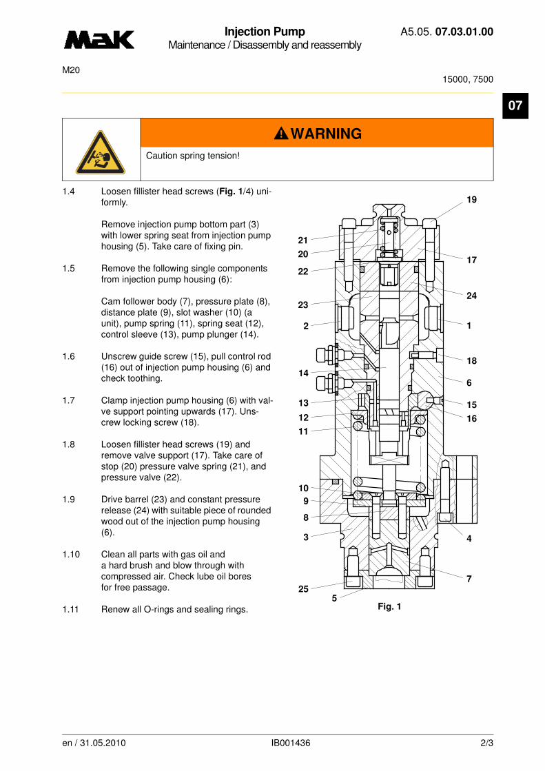
Injection PumpMaintenance / Disassembly and reassembly
A5.05. 07.03.01.00
15000, 7500M20
07
1.4 Loosen fillister head screws (Fig. 1/4) uni-formly.
Remove injection pump bottom part (3) with lower spring seat from injection pump housing (5). Take care of fixing pin.
1.5 Remove the following single components from injection pump housing (6):
Cam follower body (7), pressure plate (8), distance plate (9), slot washer (10) (a unit), pump spring (11), spring seat (12), control sleeve (13), pump plunger (14).
1.6 Unscrew guide screw (15), pull control rod (16) out of injection pump housing (6) and check toothing.
1.7 Clamp injection pump housing (6) with val-ve support pointing upwards (17). Uns-crew locking screw (18).
1.8 Loosen fillister head screws (19) and remove valve support (17). Take care of stop (20) pressure valve spring (21), and pressure valve (22).
1.9 Drive barrel (23) and constant pressure release (24) with suitable piece of rounded wood out of the injection pump housing (6).
1.10 Clean all parts with gas oil and a hard brush and blow through with compressed air. Check lube oil bores for free passage.
1.11 Renew all O-rings and sealing rings.
WARNING
Caution spring tension!
19
17
24
1
18
6
15
16
4
7
Fig. 1
21
20
22
23
2
14
13
12
11
10
9
8
3
255
en / 31.05.2010 IB001436 2/3

Injection PumpMaintenance / Disassembly and reassembly
A5.05. 07.03.01.00
15000, 7500M20
07
2. Reassembly
2.1 The reassembly is carried out in reverse order to the disassembly procedure.
2.2 Grease contact surfaces between valve support (17), constant pressure release (24) and barrel (23) thinly with absolutely clean Molykote paste “G-Rapid Plus”.
2.3 Coat threads and contact surfaces of the following screws with Molykote paste “G-Rapid Plus” and tighten crosswise with tightening torque:
Fillister head screw (Fig. 1/4)
M = 25 Nm
Fillister head screw (19)
M = 45 Nm
Imoact screws (1 and 2)
M = 50 Nm
During disassembly of the lower valve plate (5)
Fillister head screw (25)
M = 40 Nm
2.4 Check freedom of motion of the control rack.
NOTE
Insert O-rings with vaseline untwisted into slots, do not pull across sharp edges of the components.During visual inspection pay special attention to the following wear phenomena:•plunger, scores marks on the running surface. Control helix worn by cavitation or erosion•barrel: score marks in the running surface•piston with barrel, sliding fit of the piston in the barrel•impact screws, cavitation,•pressure valve: damaged contact faces, dented seat, worn pressure spring•pressure plate/cam follower body, worn plunger contact face and needle guide
•fuel supply and discharge bores in the connecting flange, cavitation, erosion
CAUTION
During reassembly see that the barrel is locked and that the marking of control rack - control sleeve and control sleeve - plunger coincide.
en / 31.05.2010 IB001436 3/3

Injection PumpMaintenance / Disassembly and reassembly
A5.05. 07.03.01.01
15000, 7500M20
07
-------
See also:
Spare parts list: B1.05.07.2.3597
Time requirement: 1 Pers./ 1,00 h
Personnel qualification: skilled engine hand
-------------------------------------------------------------------------------------------------------------------------
Operating medium: Heavy fuel and distillate fuel
Maintenance:
Disassemble injection pump if required, clean all parts and replace if necessary. Observe note!
Tools:
Torque wrench 20 - 90 Nm 1/2" W1* 1.9454-20
* not available as figure
Auxiliary material:
Molykote paste “G-Rapid Plus” *Vaseline *
** or a product of equal standard
Sequence of operations: (Fig. 1)
1. Disassembly
1.1 Clean the outside of the injection pump.
1.2 Remove and check impact screws (Fig. 1/1 and 2).
1.3 Clamp injection pump upwards with injection pump bottom part (3).
NOTE
All parts of the injection pump are manufactured with utmost precision in special workshops. This is the only guarantee for proper function. When repairing a pump, it is to be ensured that the various components of the pump, e.g. control sleeve, con-trol rack, rack pointer etc. remain together with their respective housing.
Plunger and barrel must be renewed as a unit only. In order to keep repair costs low, any parts to be reconditioned should be shipped only complete, and the possibility of interchanging must be excluded. Lapped surfaces must be preserved and not touched with fingers.
en / 31.05.2010 IB002110 1/3
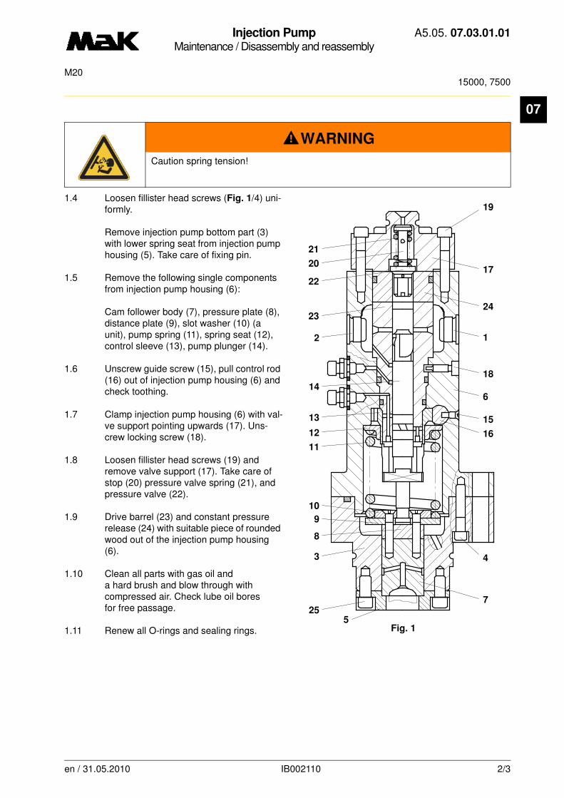
Injection PumpMaintenance / Disassembly and reassembly
A5.05. 07.03.01.01
15000, 7500M20
07
1.4 Loosen fillister head screws (Fig. 1/4) uni-formly.
Remove injection pump bottom part (3) with lower spring seat from injection pump housing (5). Take care of fixing pin.
1.5 Remove the following single components from injection pump housing (6):
Cam follower body (7), pressure plate (8), distance plate (9), slot washer (10) (a unit), pump spring (11), spring seat (12), control sleeve (13), pump plunger (14).
1.6 Unscrew guide screw (15), pull control rod (16) out of injection pump housing (6) and check toothing.
1.7 Clamp injection pump housing (6) with val-ve support pointing upwards (17). Uns-crew locking screw (18).
1.8 Loosen fillister head screws (19) and remove valve support (17). Take care of stop (20) pressure valve spring (21), and pressure valve (22).
1.9 Drive barrel (23) and constant pressure release (24) with suitable piece of rounded wood out of the injection pump housing (6).
1.10 Clean all parts with gas oil and a hard brush and blow through with compressed air. Check lube oil bores for free passage.
1.11 Renew all O-rings and sealing rings.
WARNING
Caution spring tension!
19
17
24
1
18
6
15
16
4
7
Fig. 1
21
20
22
23
2
14
13
12
11
10
9
8
3
255
en / 31.05.2010 IB002110 2/3

Injection PumpMaintenance / Disassembly and reassembly
A5.05. 07.03.01.01
15000, 7500M20
07
2. Reassembly
2.1 The reassembly is carried out in reverse order to the disassembly procedure.
2.2 Grease contact surfaces between constant pressure release (24) and barrel (23) thinly with abso-lutely clean Molykote paste “G-Rapid Plus”.
2.3 Coat threads and contact surfaces of the following screws with Molykote paste “G-Rapid Plus” and tighten crosswise with tightening torque:
Fillister head screw (Fig. 1/4)
M = 25 Nm
Fillister head screw (19)
M = 45 Nm
Imoact screws (1 and 2)
M = 50 Nm
During disassembly of the lower valve plate (5)
Fillister head screw (25)
M = 45 Nm
2.4 Check freedom of motion of the control rack.
NOTE
Insert O-rings with vaseline untwisted into slots, do not pull across sharp edges of the components.During visual inspection pay special attention to the following wear phenomena:•plunger, scores marks on the running surface. Control helix worn by cavitation or erosion•barrel: score marks in the running surface•piston with barrel, sliding fit of the piston in the barrel•impact screws, cavitation,•pressure valve: damaged contact faces, dented seat, worn pressure spring•pressure plate/cam follower body, worn plunger contact face and needle guide
•fuel supply and discharge bores in the connecting flange, cavitation, erosion
CAUTION
During reassembly see that the barrel is locked and that the marking of control rack - control sleeve and control sleeve - plunger coincide.
en / 31.05.2010 IB002110 3/3
Injection PumpMaintenance / Disassembly and reassembly
A5.05. 07.03.01.02
15000, 7500M20
07
-------
See also:
Spare parts list: B1.05.07.2.3597
Time requirement: 1 Pers./ 1,00 h
Personnel qualification: skilled engine hand
-------------------------------------------------------------------------------------------------------------------------
Operating medium: Heavy fuel and distillate fuel
Maintenance:
Disassemble injection pump if required, clean all parts and replace if necessary. Observe note!
Tools:
Torque wrench 20 - 90 Nm 1/2" W1* 1.9454-20
* not available as figure
Auxiliary material:
Molykote paste “G-Rapid Plus” *Vaseline *
** or a product of equal standard
Sequence of operations:
1. Disassembly
1.1 Clean the outside of the injection pump.
1.2 Remove and check impact screws (Fig. 1/1 and 2).
1.3 Clamp injection pump upwards with injection pump bottom part (3).
NOTE
All parts of the injection pump are manufactured with utmost precision in special workshops. This is the only guarantee for proper function. When repairing a pump, it is to be ensured that the various components of the pump, e.g. control sleeve, con-trol rack, rack pointer etc. remain together with their respective housing.
Plunger and barrel must be renewed as a unit only. In order to keep repair costs low, any parts to be reconditioned should be shipped only complete, and the possibility of interchanging must be excluded. Lapped surfaces must be preserved and not tou-ched with fingers.
en / 31.05.2010 IB003279 1/4
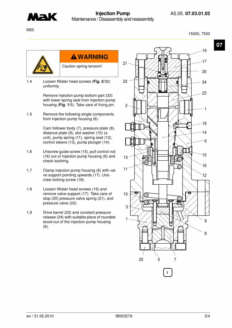
Injection PumpMaintenance / Disassembly and reassembly
A5.05. 07.03.01.02
15000, 7500M20
07
1.4 Loosen fillister head screws (Fig. 2/32) uniformly.
Remove injection pump bottom part (33) with lower spring seat from injection pump housing (Fig. 1/5). Take care of fixing pin.
1.5 Remove the following single components from injection pump housing (6):
Cam follower body (7), pressure plate (8), distance plate (9), slot washer (10) (a unit), pump spring (11), spring seat (12), control sleeve (13), pump plunger (14).
1.6 Unscrew guide screw (15), pull control rod (16) out of injection pump housing (6) and check toothing.
1.7 Clamp injection pump housing (6) with val-ve support pointing upwards (17). Uns-crew locking screw (18).
1.8 Loosen fillister head screws (19) and remove valve support (17). Take care of stop (20) pressure valve spring (21), and pressure valve (22).
1.9 Drive barrel (23) and constant pressure release (24) with suitable piece of rounded wood out of the injection pump housing (6).
WARNING
Caution spring tension!
20
17
19
23
24
14
18
16
15
6
12
9
1
7
22
21
25
13
1
3
10
5
21
11
8
en / 31.05.2010 IB003279 2/4

Injection PumpMaintenance / Disassembly and reassembly
A5.05. 07.03.01.02
15000, 7500M20
07
1.10 Dismantle the fuel outlet throttle screw (Fig.2/30) and the fuel inlet throttle screw (31).1.11 Clean all parts with gas oil and a hard brush and blow through with compressed air. Check lube oil bores for free passage.
1.12 Renew all O-rings and sealing rings.
NOTE
Insert O-rings with vaseline unt-wisted into slots, do not pull across sharp edges of the components.
During visual inspection pay special attention to the following wear phenomena:
•plunger, scores marks on the running surface. Control helix worn by cavitation or erosion
•barrel: score marks in the run-ning surface
•piston with barrel, sliding fit of the piston in the barrel
•impact screws, cavitation,
•pressure valve: damaged con-tact faces, dented seat, worn pressure spring
•pressure plate/cam follower body, worn plunger contact face and needle guide
•fuel supply and discharge bo-res in the connecting flange, ca-vitation, erosion
33 32
30
31
2
en / 31.05.2010 IB003279 3/4

Injection PumpMaintenance / Disassembly and reassembly
A5.05. 07.03.01.02
15000, 7500M20
07
2. Reassembly2.1 The reassembly is carried out in reverse order to the disassembly procedure.
2.2 Grease contact surfaces between constant pressure release (Fig. 1/24) and barrel (23) thinly with absolutely clean Molykote paste “G-Rapid Plus”.
2.3 Coat threads and contact surfaces of the following screws with Molykote paste “G-Rapid Plus” and tighten crosswise with tightening torque:
Fillister head screw (4)
M = 25 Nm
Fillister head screw (19)
M = 45 Nm
Imoact screws (1 and 2)
M = 50 Nm
During disassembly of the lower valve plate (5)
Fillister head screw (25)
M = 45 Nm
2.4 Check freedom of motion of the control rack.
CAUTION
During reassembly see that the barrel is locked and that the marking of control rack - control sleeve and control sleeve - plunger coincide.
en / 31.05.2010 IB003279 4/4

Injection PumpMaintenance / Disassembly and reassembly
A5.05. 07.03.01.03
15000, 7500M20
07
-------
See also:
Spare parts list: B1.05.07.2.3597
Time requirement: 1 Pers./ 1,00 h
Personnel qualification: skilled engine hand
-------------------------------------------------------------------------------------------------------------------------
Operating medium: Heavy fuel and distillate fuel
Maintenance:
Disassemble injection pump if required, clean all parts and replace if necessary. Observe note!
Tools:
Torque wrench 20 - 90 Nm 1/2" W1* 1.9454-20
* not available as figure
Auxiliary material:
Molykote paste “G-Rapid Plus” *Vaseline *
** or a product of equal standard
Sequence of operations:
1. Disassembly
1.1 Clean the outside of the injection pump.
1.2 Remove and check impact screws (Fig. 1/1 and 2).
1.3 Clamp injection pump upwards with injection pump bottom part (3).
NOTE
All parts of the injection pump are manufactured with utmost precision in special workshops. This is the only guarantee for proper function. When repairing a pump, it is to be ensured that the various components of the pump, e.g. control sleeve, con-trol rack, rack pointer etc. remain together with their respective housing.
Plunger and barrel must be renewed as a unit only. In order to keep repair costs low, any parts to be reconditioned should be shipped only complete, and the possibility of interchanging must be excluded. Lapped surfaces must be preserved and not touched with fingers.
en / 31.05.2010 IB024918 1/4
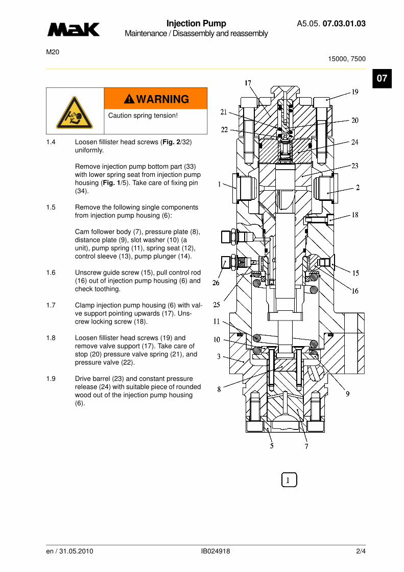
Injection PumpMaintenance / Disassembly and reassembly
A5.05. 07.03.01.03
15000, 7500M20
07
1.4 Loosen fillister head screws (Fig. 2/32) uniformly.
Remove injection pump bottom part (33) with lower spring seat from injection pump housing (Fig. 1/5). Take care of fixing pin (34).
1.5 Remove the following single components from injection pump housing (6):
Cam follower body (7), pressure plate (8), distance plate (9), slot washer (10) (a unit), pump spring (11), spring seat (12), control sleeve (13), pump plunger (14).
1.6 Unscrew guide screw (15), pull control rod (16) out of injection pump housing (6) and check toothing.
1.7 Clamp injection pump housing (6) with val-ve support pointing upwards (17). Uns-crew locking screw (18).
1.8 Loosen fillister head screws (19) and remove valve support (17). Take care of stop (20) pressure valve spring (21), and pressure valve (22).
1.9 Drive barrel (23) and constant pressure release (24) with suitable piece of rounded wood out of the injection pump housing (6).
WARNING
Caution spring tension!
en / 31.05.2010 IB024918 2/4

Injection PumpMaintenance / Disassembly and reassembly
A5.05. 07.03.01.03
15000, 7500M20
07
1.10 Dismantle the fuel outlet throttle screw (Fig.2/30) and the fuel inlet throttle screw (31).1.11 Clean all parts with gas oil and a hard brush and blow through with compressed air. Check lube oil bores for free passage.
1.12 Renew all O-rings and sealing rings.
CAUTION
If a possibly existing throttle (25) is to be exchanged, it has to be replaced, together with the connector, by the throttle-connector (26).
NOTE
Insert O-rings with vaseline unt-wisted into slots, do not pull across sharp edges of the components.
During visual inspection pay special attention to the following wear phenomena:
•plunger, scores marks on the running surface. Control helix worn by cavitation or erosion
•barrel: score marks in the run-ning surface
•piston with barrel, sliding fit of the piston in the barrel
•impact screws, cavitation,
•pressure valve: damaged con-tact faces, dented seat, worn pressure spring
•pressure plate/cam follower body, worn plunger contact face and needle guide
•fuel supply and discharge
bores in the connecting flange, cavitation, erosion
en / 31.05.2010 IB024918 3/4
Injection PumpMaintenance / Disassembly and reassembly
A5.05. 07.03.01.03
15000, 7500M20
07
2. Reassembly2.1 The reassembly is carried out in reverse order to the disassembly procedure.
2.2 Grease contact surfaces between constant pressure release (Fig. 1/24) and barrel (23) thinly with absolutely clean Molykote paste “G-Rapid Plus”.
2.3 Coat threads and contact surfaces of the following screws with Molykote paste “G-Rapid Plus” and tighten crosswise with tightening torque:
Fillister head screw (4)
M = 25 Nm
Fillister head screw (19)
M = 45 Nm
Imoact screws (1 and 2)
M = 50 Nm
During disassembly of the lower valve plate (5)
Fillister head screw (25)
M = 45 Nm
2.4 Check freedom of motion of the control rack.
CAUTION
During reassembly see that the barrel is locked and that the marking of control rack - control sleeve and control sleeve - plunger coincide.
en / 31.05.2010 IB024918 4/4
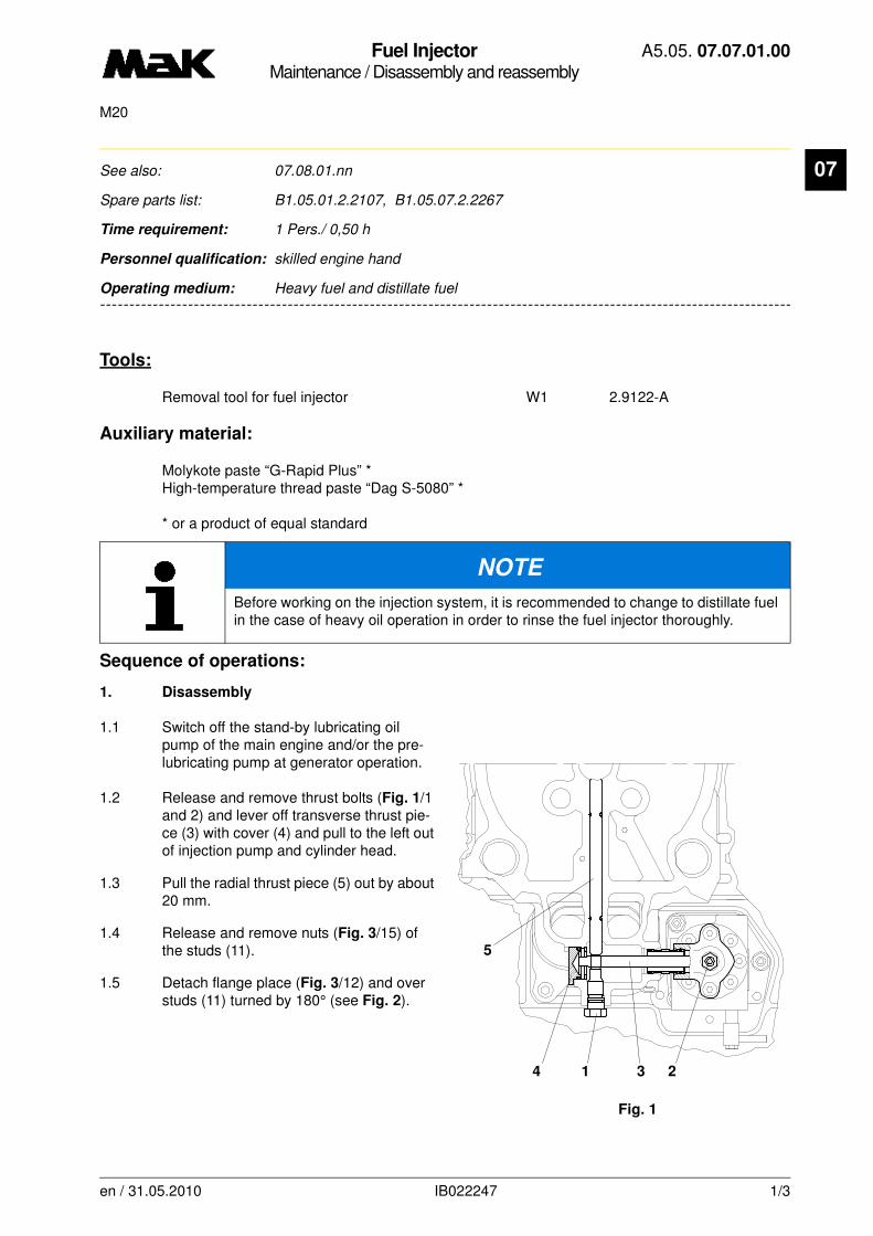
Fuel InjectorMaintenance / Disassembly and reassembly
A5.05. 07.07.01.00
M20
07
-------
See also: 07.08.01.nn
Spare parts list: B1.05.01.2.2107, B1.05.07.2.2267
Time requirement: 1 Pers./ 0,50 h
Personnel qualification: skilled engine hand
-------------------------------------------------------------------------------------------------------------------------
Operating medium: Heavy fuel and distillate fuel
Tools:
Removal tool for fuel injector W1 2.9122-A
Auxiliary material:
Molykote paste “G-Rapid Plus” *High-temperature thread paste “Dag S-5080” *
* or a product of equal standard
Sequence of operations:
1. Disassembly
1.1 Switch off the stand-by lubricating oil pump of the main engine and/or the pre-lubricating pump at generator operation.
1.2 Release and remove thrust bolts (Fig. 1/1 and 2) and lever off transverse thrust pie-ce (3) with cover (4) and pull to the left out of injection pump and cylinder head.
1.3 Pull the radial thrust piece (5) out by about 20 mm.
1.4 Release and remove nuts (Fig. 3/15) of the studs (11).
1.5 Detach flange place (Fig. 3/12) and over studs (11) turned by 180° (see Fig. 2).
NOTE
Before working on the injection system, it is recommended to change to distillate fuel in the case of heavy oil operation in order to rinse the fuel injector thoroughly.
Fig. 1
4 1 3 2
5
en / 31.05.2010 IB022247 1/3
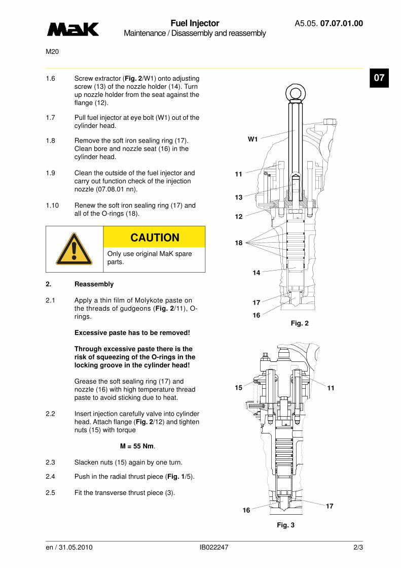
Fuel InjectorMaintenance / Disassembly and reassembly
A5.05. 07.07.01.00
M20
07
1.6 Screw extractor (Fig. 2/W1) onto adjusting screw (13) of the nozzle holder (14). Turn up nozzle holder from the seat against the flange (12).1.7 Pull fuel injector at eye bolt (W1) out of the cylinder head.
1.8 Remove the soft iron sealing ring (17). Clean bore and nozzle seat (16) in the cylinder head.
1.9 Clean the outside of the fuel injector and carry out function check of the injection nozzle (07.08.01 nn).
1.10 Renew the soft iron sealing ring (17) and all of the O-rings (18).
2. Reassembly
2.1 Apply a thin film of Molykote paste on the threads of gudgeons (Fig. 2/11), O-rings.
Excessive paste has to be removed!
Through excessive paste there is the
risk of squeezing of the O-rings in the
locking groove in the cylinder head!
Grease the soft sealing ring (17) and nozzle (16) with high temperature thread paste to avoid sticking due to heat.
2.2 Insert injection carefully valve into cylinder head. Attach flange (Fig. 2/12) and tighten nuts (15) with torque
M = 55 Nm.
2.3 Slacken nuts (15) again by one turn.
2.4 Push in the radial thrust piece (Fig. 1/5).
2.5 Fit the transverse thrust piece (3).
CAUTION
Only use original MaK spare parts.
Fig. 216
17
14
18
12
13
11
W1
Fig. 3
15
16
11
17
en / 31.05.2010 IB022247 2/3

Fuel InjectorMaintenance / Disassembly and reassembly
A5.05. 07.07.01.00
M20
07
2.6 Tighteen the thrust bolts (1 and 2) manually in alternating order, becauce of tapered seat of the transverse thrust piece (3) on the injection pump.2.7 First tighten thrust bolt (2) and then thrust bolt (1) with a torque of
M = 85 Nm.
2.8 Tighten nuts ( Fig. 3/15) once again with a torque of
M = 30 Nm.
en / 31.05.2010 IB022247 3/3
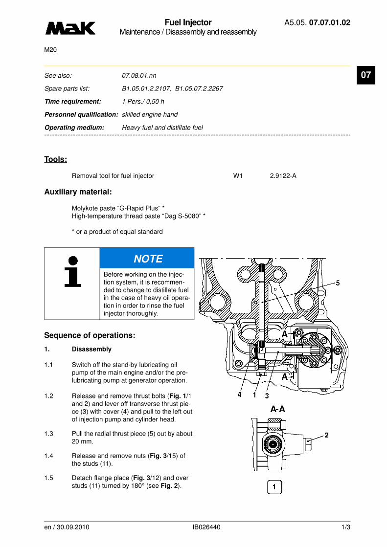
Fuel InjectorMaintenance / Disassembly and reassembly
A5.05. 07.07.01.02
M20
07
-------
See also: 07.08.01.nn
Spare parts list: B1.05.01.2.2107, B1.05.07.2.2267
Time requirement: 1 Pers./ 0,50 h
Personnel qualification: skilled engine hand
-------------------------------------------------------------------------------------------------------------------------
Operating medium: Heavy fuel and distillate fuel
Tools:
Removal tool for fuel injector W1 2.9122-A
Auxiliary material:
Molykote paste “G-Rapid Plus” *High-temperature thread paste “Dag S-5080” *
* or a product of equal standard
Sequence of operations:
1. Disassembly
1.1 Switch off the stand-by lubricating oil pump of the main engine and/or the pre-lubricating pump at generator operation.
1.2 Release and remove thrust bolts (Fig. 1/1 and 2) and lever off transverse thrust pie-ce (3) with cover (4) and pull to the left out of injection pump and cylinder head.
1.3 Pull the radial thrust piece (5) out by about 20 mm.
1.4 Release and remove nuts (Fig. 3/15) of the studs (11).
1.5 Detach flange place (Fig. 3/12) and over studs (11) turned by 180° (see Fig. 2).
NOTE
Before working on the injec-tion system, it is recommen-ded to change to distillate fuel in the case of heavy oil opera-tion in order to rinse the fuel injector thoroughly.
en / 30.09.2010 IB026440 1/3
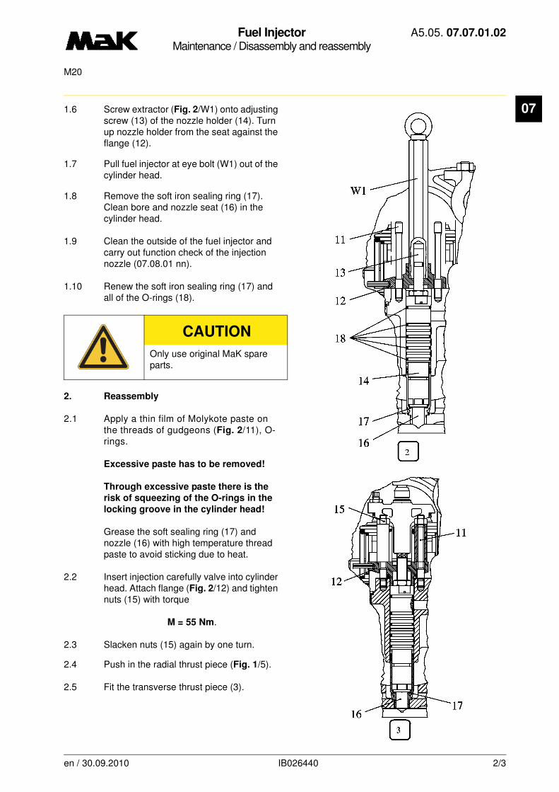
Fuel InjectorMaintenance / Disassembly and reassembly
A5.05. 07.07.01.02
M20
07
1.6 Screw extractor (Fig. 2/W1) onto adjusting screw (13) of the nozzle holder (14). Turn up nozzle holder from the seat against the flange (12).1.7 Pull fuel injector at eye bolt (W1) out of the cylinder head.
1.8 Remove the soft iron sealing ring (17). Clean bore and nozzle seat (16) in the cylinder head.
1.9 Clean the outside of the fuel injector and carry out function check of the injection nozzle (07.08.01 nn).
1.10 Renew the soft iron sealing ring (17) and all of the O-rings (18).
2. Reassembly
2.1 Apply a thin film of Molykote paste on the threads of gudgeons (Fig. 2/11), O-rings.
Excessive paste has to be removed!
Through excessive paste there is the
risk of squeezing of the O-rings in the
locking groove in the cylinder head!
Grease the soft sealing ring (17) and nozzle (16) with high temperature thread paste to avoid sticking due to heat.
2.2 Insert injection carefully valve into cylinder head. Attach flange (Fig. 2/12) and tighten nuts (15) with torque
M = 55 Nm.
2.3 Slacken nuts (15) again by one turn.
2.4 Push in the radial thrust piece (Fig. 1/5).
2.5 Fit the transverse thrust piece (3).
CAUTION
Only use original MaK spare parts.
en / 30.09.2010 IB026440 2/3
Fuel InjectorMaintenance / Disassembly and reassembly
A5.05. 07.07.01.02
M20
07
2.6 Tighteen the thrust bolts (1 and 2) manually in alternating order, becauce of tapered seat of the transverse thrust piece (3) on the injection pump.2.7 First tighten thrust bolt (2) and then thrust bolt (1) with a torque of
M = 85 Nm.
2.8 Tighten nuts ( Fig. 3/15) once again with a torque of
M = 30 Nm.
en / 30.09.2010 IB026440 3/3

Fuel InjectorMaintenance / Adjust
A5.05. 07.08.01.01
M20
07
-------
See also: 07.07.01.nn, 07.09.01.nn
Spare parts list: B1.05.07.2.2267, B1.05.07.2.2260
Time requirement: 1 Pers./ 0,50 h
Personnel qualification: skilled engine hand
-------------------------------------------------------------------------------------------------------------------------
Operating medium: Heavy fuel and distillate fuel
Tools:
Nozzle tester W1 1.9470 BAdapter/Nozzle holder - nozzle tester W2 2.9208 APressure pipe W3 1.9470-051
DANGER
When checking the opening pressure: Risk of accident! Keep your hands off the fuel jet!
NOTE
Proper function of the injection nozzlescan only be assessed from the behaviour of the exhaust gas temperatures or smoke emission behaviour.
The fuel injector should only be checked in case of a significant deviation of the
exhaust gas temperature from the respective cylinder value. For this purpose
the nozzle tester is provided, which can also be used for checking the nozzle
holes for unobstructed passage.
By means of the nozzle tester the behaviour of the nozzle in operation cannot be reproduced, because the flow rates and the related pressure build-up are not compa-rable with the real conditions on the engine, i.e. the spray pattern alone gives no indi-cation of the function of the nozzle.
On the nozzle tester the specified opening pressure is to be adjusted after assembly of the nozzle.
A drop in opening pressure after a short operating time (setting of nozzle spring and needle) is normal.
en / 31.05.2010 IB026385 1/2

Fuel InjectorMaintenance / Adjust
A5.05. 07.08.01.01
M20
07
Sequence of operations:1. Remove carbon deposits from the nozzle with a hard brush (no wire brush).
2. Check the nozzle hole for sharp edges, ovalization, corrosion and damage.
3. Place the injector with the adapter (W2) in the tester (W1).
4. Connect the injector delivery pipe (W3).
5. Increase the pressure by means of the pump until the nozzle opens. Determine injector opening pressure
and free passage of the nozzle holes.
5.1 For adjusting the opening pressure slacken the lock nut (1) and turn the adjusting screw (2) until the correct opening pressure is adjusted (see 5.2 and 5.3). Tighten the lock nut (1).
5.2 When using a new fuel injector or a new nozzle element (8) and a new nozzle spring (4) the nozzle opening pressure
is to be adjusted according to the
testbed record (A1.10.).
5.3 When continuing to use the old nozzle element (8) and/or the old nozzle spring (4) the opening pressure is to be adjusted according to the testbed record value (A1.10.) minus 10%.
Ptest = 350 bar - 10% = 315 bar
NOTE
If a high portion of fuel is lea-king or if the nozzle holes are clogged and the nozzle alrea-dy opens below the minimum
nozzle opening pressure of
230 bar, repair or replace the injector according to (07.09.01.nn).
en / 31.05.2010 IB026385 2/2
Fuel InjectorMaintenance / Adjust
A5.05. 07.08.01.02
M20
07
-------
See also: 07.07.01.nn, 07.09.01.nn
Spare parts list: B1.05.07.2.2267, B1.05.07.2.2260
Time requirement: 1 Pers./ 0,50 h
Personnel qualification: skilled engine hand
-------------------------------------------------------------------------------------------------------------------------
Operating medium: Heavy fuel and distillate fuel
Tools:
Nozzle tester W1 1.9470 BAdapter/Nozzle holder - nozzle tester W2 2.9208 APressure pipe W3 1.9470-051
DANGER
When checking the opening pressure: Risk of accident! Keep your hands off the fuel jet!
NOTE
Proper function of the injection nozzlescan only be assessed from the behaviour of the exhaust gas temperatures or smoke emission behaviour.
The fuel injector should only be checked in case of a significant deviation of the
exhaust gas temperature from the respective cylinder value. For this purpose
the nozzle tester is provided, which can also be used for checking the nozzle
holes for unobstructed passage.
By means of the nozzle tester the behaviour of the nozzle in operation cannot be reproduced, because the flow rates and the related pressure build-up are not compa-rable with the real conditions on the engine, i.e. the spray pattern alone gives no indi-cation of the function of the nozzle.
On the nozzle tester the specified opening pressure is to be adjusted after assembly of the nozzle.
A drop in opening pressure after a short operating time (setting of nozzle spring and needle) is normal.
en / 31.05.2010 IB026393 1/2
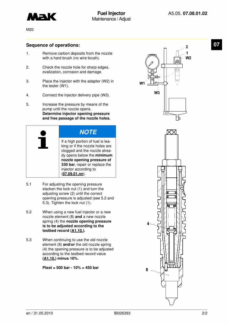
Fuel InjectorMaintenance / Adjust
A5.05. 07.08.01.02
M20
07
Sequence of operations:1. Remove carbon deposits from the nozzle with a hard brush (no wire brush).
2. Check the nozzle hole for sharp edges, ovalization, corrosion and damage.
3. Place the injector with the adapter (W2) in the tester (W1).
4. Connect the injector delivery pipe (W3).
5. Increase the pressure by means of the pump until the nozzle opens. Determine injector opening pressure
and free passage of the nozzle holes.
5.1 For adjusting the opening pressure slacken the lock nut (1) and turn the adjusting screw (2) until the correct opening pressure is adjusted (see 5.2 and 5.3). Tighten the lock nut (1).
5.2 When using a new fuel injector or a new nozzle element (8) and a new nozzle spring (4) the nozzle opening pressure
is to be adjusted according to the
testbed record (A1.10.).
5.3 When continuing to use the old nozzle element (8) and/or the old nozzle spring (4) the opening pressure is to be adjusted according to the testbed record value (A1.10.) minus 10%.
Ptest = 500 bar - 10% = 450 bar
NOTE
If a high portion of fuel is lea-king or if the nozzle holes are clogged and the nozzle alrea-dy opens below the minimum
nozzle opening pressure of
330 bar, repair or replace the injector according to (07.09.01.nn).
en / 31.05.2010 IB026393 2/2
Fuel InjectorRepair / Disassembly and reassembly
A5.05. 07.09.01.00
M20
07
-------
See also: 07.07.01.nn, 07.08.01.nn
Spare parts list: B1.05.07.2.2267
Time requirement: 1 Pers./ 0,50 h
Personnel qualification: skilled engine hand
-------------------------------------------------------------------------------------------------------------------------
Operating medium: Heavy fuel and distillate fuel
Tools:
Torque wrench 60 - 420 Nm W1 * 1.9454-60
* not available as figure
Auxiliary material:
Molykote paste "G-Rapid" **
** or a product of equal standard
NOTE
The fuel injector valve should only be disassembled if the inspection (07.08.01.nn.)
yields deficiencies (e.g. leaking, too low opening pressure, poor atomization).
All parts of the injection system are produced with utmost precision in special work-shops. This is the only guarantee for a proper function. For this reason, it is impossi-ble for the operator to repair it and the necessary maintenance work should be limited to
•cleaning
•inspection of opening pressure and tightness
•replacement of wearing parts making use of original parts and replacement ele-ments.
In order to keep repair costs low, elements in need of repair should be got ready for shipment as complete units and clearly marked to prevent them from being mixed up.
en / 31.05.2010 IB001412 1/2

Fuel InjectorRepair / Disassembly and reassembly
A5.05. 07.09.01.00
M20
07
Sequence of operations:1. Disassembly
1.1 Loosen nut (Fig. 1/1) and relieve pressure spring (2) by unscrewing setting spindle (3).
1.2 Loosen and screw off nozzle nut (4) by turning to the left.
1.3 Remove nozzle element (5) with needle, without damaging the lapped surfaces or coming into contact with the fingers. Take care of cylindrical pin (6).
1.4 Unscrew adjusting screw, check pressure spring and compression bolt (7) visually.
1.5 Clean all parts with gas oil.
1.6 Insert nozzle needle with gas oil into the nozzle element and check whether the nozzle needle falls onto the seat through its own weight. If the needle hangs or sticks, replace it together with the element.
1.7 Subject all parts, especially seat and contact faces, to a visual inspection. Replace defective parts.
2. Reassembly
2.1 Wipe all contact faces dry with clean paper.
2.2 Renew O-ring seal (8).
2.3 Coat thread of the fuel injector housing and the recess of the nozzle element with Molykote paste “G-Rapid Plus”.
2.4 The reassembly of the fuel injector is carried out in reverse order to the disassembly procedure.
2.5 Tighten nozzle nut (4) with a torque of
M = 250 Nm.
2.6 Adjust fuel injector in accordance with 07.08.01.nn.
3
1
8
2
7
6
5
4
Fig. 1
en / 31.05.2010 IB001412 2/2

Fuel InjectorRepair / Disassembly and reassembly
A5.05. 07.09.01.01
7500M20
07
-------
See also: 07.07.01.nn, 07.08.01.nn
Spare parts list: B1.05.07.2.2267
Time requirement: 1 Pers./ 0,50 h
Personnel qualification: skilled engine hand
-------------------------------------------------------------------------------------------------------------------------
Operating medium: Heavy fuel and distillate fuel
Tools:
Torque wrench 60 - 420 Nm W1 * 1.9454-60
* not available as figure
Auxiliary material:
Molykote paste "G-Rapid" **
** or a product of equal standard
NOTE
The fuel injector valve should only be disassembled if the inspection (07.08.01.nn.)
yields deficiencies (e.g. leaking, too low opening pressure, poor atomization).
All parts of the injection system are produced with utmost precision in special work-shops. This is the only guarantee for a proper function. For this reason, it is impossi-ble for the operator to repair it and the necessary maintenance work should be limited to
•cleaning
•inspection of opening pressure and tightness
•replacement of wearing parts making use of original parts and replacement ele-ments.
In order to keep repair costs low, elements in need of repair should be got ready for shipment as complete units and clearly marked to prevent them from being mixed up.
en / 31.05.2010 IB026415 1/2

Fuel InjectorRepair / Disassembly and reassembly
A5.05. 07.09.01.01
7500M20
07
Sequence of operations:1. Disassembly
1.1 Loosen nut (Fig. 1/1) and relieve pressure spring (2) by unscrewing setting spindle (3).
1.2 Loosen and screw off nozzle nut (4) by turning to the left.
1.3 Remove nozzle element (5) with needle, without damaging the lapped surfaces or coming into contact with the fingers. Take care of cylindrical pin (6).
1.4 Unscrew adjusting screw, check pressure spring and compression bolt (7) visually.
1.5 Clean all parts with gas oil.
1.6 Insert nozzle needle with gas oil into the nozzle element and check whether the nozzle needle falls onto the seat through its own weight. If the needle hangs or sticks, replace it together with the element.
1.7 Subject all parts, especially seat and contact faces, to a visual inspection. Replace defective parts.
2. Reassembly
2.1 Wipe all contact faces dry with clean paper.
2.2 Renew O-ring seal (8).
2.3 Coat thread of the fuel injector housing and the recess of the nozzle element with Molykote paste “G-Rapid Plus”.
2.4 The reassembly of the fuel injector is carried out in reverse order to the disassembly procedure.
2.5 Tighten nozzle nut (4) with a torque of
M = 250-20 Nm.
2.6 Adjust fuel injector in accordance with 07.08.01.nn.
3
1
2
4
5
8
7
6
en / 31.05.2010 IB026415 2/2
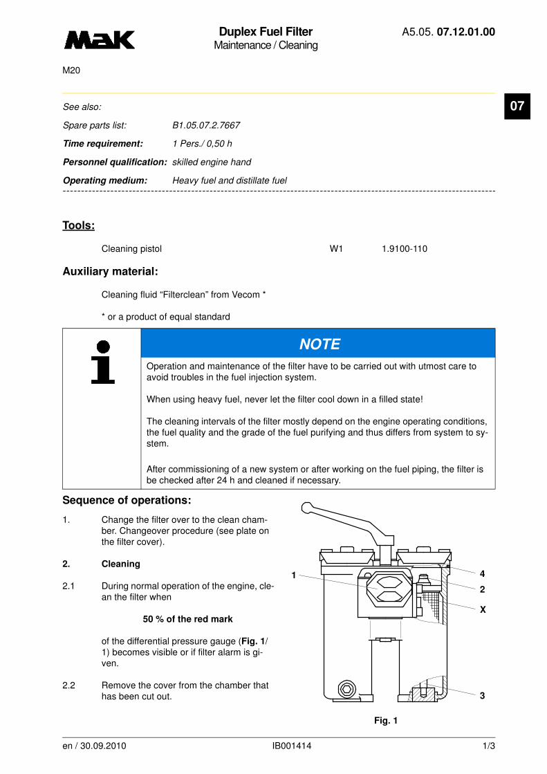
Duplex Fuel FilterMaintenance / Cleaning
A5.05. 07.12.01.00
M20
07
-------
See also:
Spare parts list: B1.05.07.2.7667
Time requirement: 1 Pers./ 0,50 h
Personnel qualification: skilled engine hand
-------------------------------------------------------------------------------------------------------------------------
Operating medium: Heavy fuel and distillate fuel
Tools:
Cleaning pistol W1 1.9100-110
Auxiliary material:
Cleaning fluid “Filterclean” from Vecom *
* or a product of equal standard
Sequence of operations:
1. Change the filter over to the clean cham-ber. Changeover procedure (see plate on the filter cover).
2. Cleaning
2.1 During normal operation of the engine, cle-an the filter when
50 % of the red mark
of the differential pressure gauge (Fig. 1/1) becomes visible or if filter alarm is gi-ven.
2.2 Remove the cover from the chamber that has been cut out.
NOTE
Operation and maintenance of the filter have to be carried out with utmost care to avoid troubles in the fuel injection system.
When using heavy fuel, never let the filter cool down in a filled state!
The cleaning intervals of the filter mostly depend on the engine operating conditions, the fuel quality and the grade of the fuel purifying and thus differs from system to sy-stem.
After commissioning of a new system or after working on the fuel piping, the filter is be checked after 24 h and cleaned if necessary.
1 4
2
X
3
Fig. 1
en / 30.09.2010 IB001414 1/3
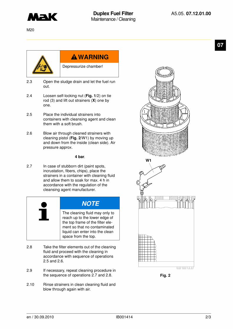
Duplex Fuel FilterMaintenance / Cleaning
A5.05. 07.12.01.00
M20
07
2.3 Open the sludge drain and let the fuel run out.
2.4 Loosen self-locking nut (Fig. 1/2) on tie rod (3) and lift out strainers (X) one by one.
2.5 Place the individual strainers into containers with cleansing agent and clean them with a soft brush.
2.6 Blow air through cleaned strainers with cleaning pistol (Fig. 2/W1) by moving up and down from the inside (clean side). Air pressure approx.
4 bar.
2.7 In case of stubborn dirt (paint spots, incrustation, fibers, chips), place the strainers in a container with cleaning fluid and allow them to soak for max. 4 h in accordance with the regulation of the cleansing agent manufacturer.
2.8 Take the filter elements out of the cleaning fluid and proceed with the cleaning in accordance with sequence of operations 2.5 and 2.6.
2.9 If necessary, repeat cleaning procedure in the sequence of operations 2.7 and 2.8.
2.10 Rinse strainers in clean cleaning fluid and blow through again with air.
WARNING
Depressurize chamber!
NOTE
The cleaning fluid may only to reach up to the lower edge of the top frame of the filter ele-ment so that no contaminated liquid can enter into the clean space from the top.
W1
Fig. 2
en / 30.09.2010 IB001414 2/3
Duplex Fuel FilterMaintenance / Cleaning
A5.05. 07.12.01.00
M20
07
2.11 Inspect the gauze of all strainers on the inside and outside for damage and replace if required2.12 Put a strong light behind the gauze and check success of the cleaning operation. Repeat if necessary.
2.13 Telescope the strainers again (Fig. 1/X), insert them into the chamber and tighten the nut (2) slightly.
2.14 Replace the gasket (4) and fit the cover.
2.15 Fill the filter chamber and vent it (see the plate on the filter cover).
CAUTION
The individual strainers are connected in parallel, and damage on only one filter ele-ment means malfunction of the entire element.
en / 30.09.2010 IB001414 3/3

Duplex Fuel Preliminary FilterMaintenance / Cleaning
A5.05. 07.12.02.02
750M20/M32/M282/M332C/M452/M453C/M551/M552C/M601/M601C
07
-------
See also:
Spare parts list: B1.05.07.1.7668
Time requirement: 1 Pers./ 1,00 h
Personnel qualification: skilled engine hand
-------------------------------------------------------------------------------------------------------------------------
Operating medium: Heavy fuel and distillate fuel
Maintenance:
Cleaning of the filter every 750 h
Tools:
Cleaning pistol W1 1.9100-110
Auxiliary material:
Cleaner “Filterclean” of Vecom *
* or a product of equal standard
Note:Operation and maintenance of the filter have to be carried out with utmost care to avoid troubles in the fuel system.
The cleaning intervals of the filter mostly depend on the engine operation conditions and the fuel quality and therefore are different from unit to unit.
When starting up a new plant or after doing some work on the fuel piping, check the filter after 24 hours and clean it if necessary.
Sequence of operations:
1. Change the filter over to the clean chamber. See the proce-dure from the plate on the filter cover.
2. Cleaning
2.1 Remove the cover from the chamber that has been cut out.
2.2 Open the sludge drain and let the fuel run out.
2.3 Withdraw the filter element (Fig. 1).
2.4 Rinse the chamber with gas oil.
en / 05.06.2000 IB022107 1/2
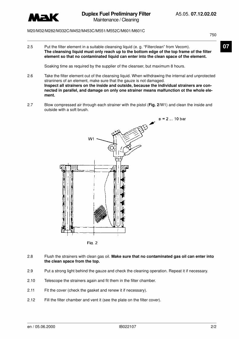
Duplex Fuel Preliminary FilterMaintenance / Cleaning
A5.05. 07.12.02.02
750M20/M32/M282/M332C/M452/M453C/M551/M552C/M601/M601C
07
2.5 Put the filter element in a suitable cleansing liquid (e. g. “Filterclean” from Vecom).The cleansing liquid must only reach up to the bottom edge of the top frame of the filterelement so that no contaminated liquid can enter into the clean space of the element.
Soaking time as required by the supplier of the cleanser, but maximum 8 hours.
2.6 Take the filter element out of the cleansing liquid. When withdrawing the internal and unprotected straniners of an element, make sure that the gauze is not damaged. Inspect all strainers on the inside and outside, because the individual strainers are con-
nected in parallel, and damage on only one strainer means malfunction ot the whole ele-
ment.
2.7 Blow compressed air through each strainer with the pistol (Fig. 2/W1) and clean the inside and outside with a soft brush.
2.8 Flush the strainers with clean gas oil. Make sure that no contaminated gas oil can enter into
the clean space from the top.
2.9 Put a strong light behind the gauze and check the cleaning operation. Repeat it if necessary.
2.10 Telescope the strainers again and fit them in the filter chamber.
2.11 Fit the cover (check the gasket and renew it if necessary).
2.12 Fill the filter chamber and vent it (see the plate on the filter cover).
en / 05.06.2000 IB022107 2/2
Duplex Fuel Preliminary FilterMaintenance / Cleaning
A5.05. 07.12.02.04
750M20-M601C
07
-------
See also:
Spare parts list: B1.05.07.1.7668
Time requirement: 1 Pers./ 1,00 h
Personnel qualification: skilled engine hand
-------------------------------------------------------------------------------------------------------------------------
Operating medium: Heavy fuel and distillate fuel
Maintenance:
Cleaning of the filter every 750 h
Auxiliary material:
Cleaner “Filterclean” of Vecom *
* or a product of equal standard
.
NOTE
Operation and maintenance of the filter have to be carried out with utmost care to avoid troubles in the fuel system.
The cleaning intervals of the filter mostly depend on the engine operation conditions and the fuel quality and therefore are different from unit to unit.
When starting up a new plant or after doing some work on the fuel piping, check the filter after 24 hours and clean it if necessary
en / 16.12.2010 IB022114 1/2
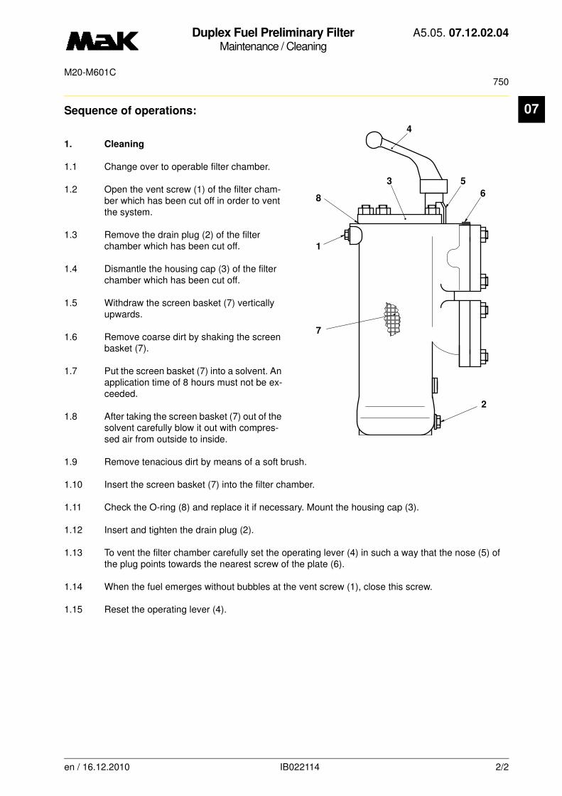
Duplex Fuel Preliminary FilterMaintenance / Cleaning
A5.05. 07.12.02.04
750M20-M601C
07
Sequence of operations:1. Cleaning
1.1 Change over to operable filter chamber.
1.2 Open the vent screw (1) of the filter cham-ber which has been cut off in order to vent the system.
1.3 Remove the drain plug (2) of the filter chamber which has been cut off.
1.4 Dismantle the housing cap (3) of the filter chamber which has been cut off.
1.5 Withdraw the screen basket (7) vertically upwards.
1.6 Remove coarse dirt by shaking the screen basket (7).
1.7 Put the screen basket (7) into a solvent. An application time of 8 hours must not be ex-ceeded.
1.8 After taking the screen basket (7) out of the solvent carefully blow it out with compres-sed air from outside to inside.
1.9 Remove tenacious dirt by means of a soft brush.
1.10 Insert the screen basket (7) into the filter chamber.
1.11 Check the O-ring (8) and replace it if necessary. Mount the housing cap (3).
1.12 Insert and tighten the drain plug (2).
1.13 To vent the filter chamber carefully set the operating lever (4) in such a way that the nose (5) of the plug points towards the nearest screw of the plate (6).
1.14 When the fuel emerges without bubbles at the vent screw (1), close this screw.
1.15 Reset the operating lever (4).
4
5
6
2
7
1
8
3
en / 16.12.2010 IB022114 2/2

Fuel Feed PumpMaintenance / Disassembly and reassembly
A5.05. 07.13.01.00
15000M20
07
-------
See also:
Spare parts list: B1.05.07.2.6480
Time requirement: 1 Pers./ 0,50 h
Personnel qualification: skilled engine hand
-------------------------------------------------------------------------------------------------------------------------
Operating medium: Heavy fuel and distillate fuel
Maintenance:
The fuel feed pump is to be disassembled every 15,000 hours of operation and the drive checked for wear.
Tools:
Torque wrench 40 - 180 Nm 1/2" W1 * 1.9454-40
* not available as figure
Auxiliary material:
Molykote paste “G-Rapid Plus” *Silicone sealing compound “Dirco Gray” *
* or a product of equal standard
Sequence of operations:
1. Disassembly
1.1 Close stop valves.
1.2 Discharge fuel from lines.
1.3 Disconnect lines at the pump.
1.4 Loosen fastening screws and pull fuel feed pump (Fig. 1/1) with coupling half out of the drive housing (2).
1.5 Remove drive housing (2) from pump car-rier plate and pull out of the cylinder block and crankcase with toothed wheel (3).
1.6 Loosen hexagon screw (4) and pull toothed wheel off (3) the drive shaft (5) with removal tool (W).
NOTE
If the fuel feed pump cannot be used due to natural wear and tear, it should be replaced. The installation of spare parts cannot reproduce the original performance according to the manufacturers.
Fig. 1
3W
2
1
Z
W
5
4
3
en / 31.05.2010 IB022122 1/3
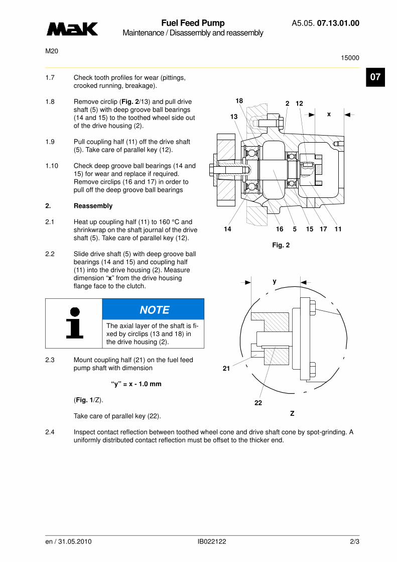
Fuel Feed PumpMaintenance / Disassembly and reassembly
A5.05. 07.13.01.00
15000M20
07
1.7 Check tooth profiles for wear (pittings, crooked running, breakage).1.8 Remove circlip (Fig. 2/13) and pull drive shaft (5) with deep groove ball bearings (14 and 15) to the toothed wheel side out of the drive housing (2).
1.9 Pull coupling half (11) off the drive shaft (5). Take care of parallel key (12).
1.10 Check deep groove ball bearings (14 and 15) for wear and replace if required. Remove circlips (16 and 17) in order to pull off the deep groove ball bearings
2. Reassembly
2.1 Heat up coupling half (11) to 160 °C and shrinkwrap on the shaft journal of the drive shaft (5). Take care of parallel key (12).
2.2 Slide drive shaft (5) with deep groove ball bearings (14 and 15) and coupling half (11) into the drive housing (2). Measure dimension “x” from the drive housing flange face to the clutch.
2.3 Mount coupling half (21) on the fuel feed pump shaft with dimension
“y” = x - 1.0 mm
(Fig. 1/Z).
Take care of parallel key (22).
2.4 Inspect contact reflection between toothed wheel cone and drive shaft cone by spot-grinding. A uniformly distributed contact reflection must be offset to the thicker end.
NOTE
The axial layer of the shaft is fi-xed by circlips (13 and 18) in the drive housing (2).
Fig. 2
x
218
13
14 16 5 15 17 11
12
Z
y
21
22
en / 31.05.2010 IB022122 2/3
Fuel Feed PumpMaintenance / Disassembly and reassembly
A5.05. 07.13.01.00
15000M20
07
2.5 Heat up toothed wheel (Fig. 1/3) to approx. 150 °C and fit onto the corresponding drive shaft cone up to stop (conical surfaces of the cones free from grease and dry) and immediately lubricate thread and contact surface of the hexagon screw (4) and washer with Molykote paste “G-Rapid Plus” and tighten with a torque ofM = 60 Nm.
Insert drive housing (2) into cylinder block and crankcase carefully with toothed wheel (3) (tooth profiles of the drive toothed wheels must mesh with each other) and mount at the pump carrier plate with sealing compound (backlash = 0.24 mm - 0.5 mm).
2.6 Mount fuel feed pump (1) and connect fuel lines.
2.7 Check lube oil supply of the toothed wheels.
2.8 Open stop valves and vent lines.
2.9 Check tightness.
en / 31.05.2010 IB022122 3/3

Fuel Distributor Line/Manifold LineRepair / Disassembly and reassembly
A5.05. 07.15.01.00
M20
07
-------
See also:
Spare parts list: B1.05.07.2.8510
Time requirement: 1 Pers./ 0,50 h
Personnel qualification: skilled engine hand
-------------------------------------------------------------------------------------------------------------------------
Operating medium: Heavy fuel and distillate fuel
Tools:
Torque wrench 20 - 90 Nm W1 * 1.9454-20* not available as figure
Auxiliary material:
Molykote paste “G-Rapid Plus” **** or a product of equal standard
Sequence of operations:
1. Disassembly
1.1 Drain fuel distributor line and manifold line (drain spigot at anti-drive end above fuel double filter).
1.2 Disassemble covering.
1.3 Loosen screws (Fig. 1/1 and 2).
1.4 Remove distributor housing (3) with equalizer (4).
1.5 Pull equalizer (4) out of distributor housing (3).
2 4 2 2
2 2
Z
Fig. 1
1 3
en / 21.07.93 IB002028 1/2
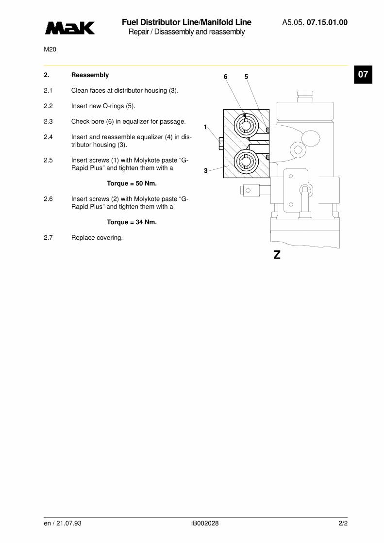
Fuel Distributor Line/Manifold LineRepair / Disassembly and reassembly
A5.05. 07.15.01.00
M20
07
2. Reassembly2.1 Clean faces at distributor housing (3).
2.2 Insert new O-rings (5).
2.3 Check bore (6) in equalizer for passage.
2.4 Insert and reassemble equalizer (4) in dis-tributor housing (3).
2.5 Insert screws (1) with Molykote paste “G-Rapid Plus” and tighten them with a
Torque = 50 Nm.
2.6 Insert screws (2) with Molykote paste “G-Rapid Plus” and tighten them with a
Torque = 34 Nm.
2.7 Replace covering.
6 5
3
1
Z
en / 21.07.93 IB002028 2/2
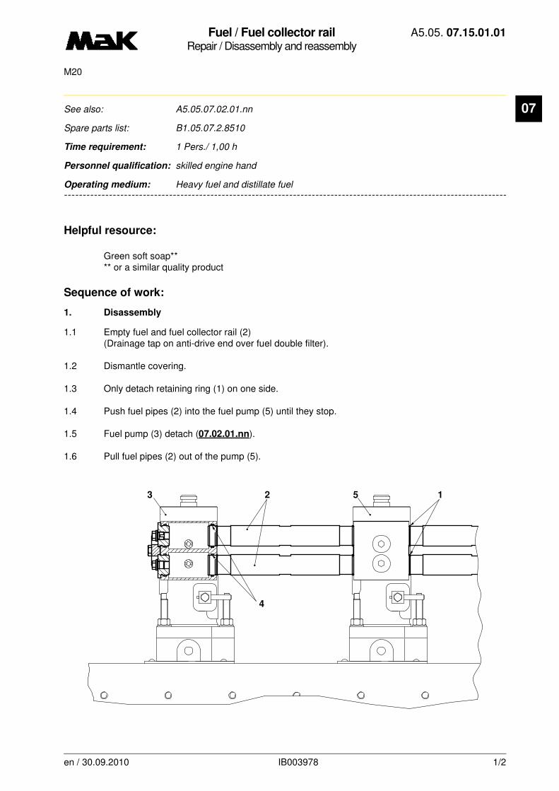
Fuel / Fuel collector railRepair / Disassembly and reassembly
A5.05. 07.15.01.01
M20
07
-------
See also: A5.05.07.02.01.nn
Spare parts list: B1.05.07.2.8510
Time requirement: 1 Pers./ 1,00 h
Personnel qualification: skilled engine hand
-------------------------------------------------------------------------------------------------------------------------
Operating medium: Heavy fuel and distillate fuel
Helpful resource:
Green soft soap** ** or a similar quality product
Sequence of work:
1. Disassembly
1.1 Empty fuel and fuel collector rail (2) (Drainage tap on anti-drive end over fuel double filter).
1.2 Dismantle covering.
1.3 Only detach retaining ring (1) on one side.
1.4 Push fuel pipes (2) into the fuel pump (5) until they stop.
1.5 Fuel pump (3) detach (07.02.01.nn).
1.6 Pull fuel pipes (2) out of the pump (5).
152
4
3
en / 30.09.2010 IB003978 1/2

Fuel / Fuel collector railRepair / Disassembly and reassembly
A5.05. 07.15.01.01
M20
07
2. Assembly2.1 Insert new O-rings (4) with green soft soap in both injection pumps.
2.2 Push fuel pipe ends into the fuel pump without retaining rings until they stop.
2.3 Assemble fuel pump (3).
2.4 Push fuel pipes (2) into fuel pump (3) until they stop.
2.5 Assemble retaining rings (1).
en / 30.09.2010 IB003978 2/2
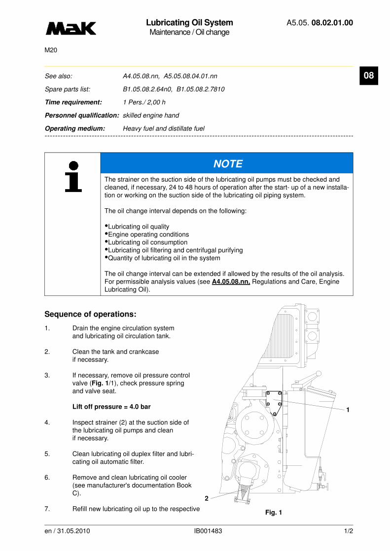
Lubricating Oil SystemMaintenance / Oil change
A5.05. 08.02.01.00
M20
08
-------
See also: A4.05.08.nn, A5.05.08.04.01.nn
Spare parts list: B1.05.08.2.64n0, B1.05.08.2.7810
Time requirement: 1 Pers./ 2,00 h
Personnel qualification: skilled engine hand
-------------------------------------------------------------------------------------------------------------------------
Operating medium: Heavy fuel and distillate fuel
Sequence of operations:
1. Drain the engine circulation system and lubricating oil circulation tank.
2. Clean the tank and crankcase if necessary.
3. If necessary, remove oil pressure control valve (Fig. 1/1), check pressure spring and valve seat.
Lift off pressure = 4.0 bar
4. Inspect strainer (2) at the suction side of the lubricating oil pumps and clean if necessary.
5. Clean lubricating oil duplex filter and lubri-cating oil automatic filter.
6. Remove and clean lubricating oil cooler (see manufacturer's documentation Book C).
7. Refill new lubricating oil up to the respective mark on the sump tank (lubricating oil quality, see
NOTE
The strainer on the suction side of the lubricating oil pumps must be checked and cleaned, if necessary, 24 to 48 hours of operation after the start- up of a new installa-tion or working on the suction side of the lubricating oil piping system.
The oil change interval depends on the following:
•Lubricating oil quality•Engine operating conditions •Lubricating oil consumption•Lubricating oil filtering and centrifugal purifying•Quantity of lubricating oil in the system
The oil change interval can be extended if allowed by the results of the oil analysis. For permissible analysis values (see A4.05.08.nn, Regulations and Care, Engine Lubricating Oil).
1
2
Fig. 1
en / 31.05.2010 IB001483 1/2

Lubricating Oil SystemMaintenance / Oil change
A5.05. 08.02.01.00
M20
08
A4.05.08.nn).8. Refill lubricating oil system and start the stand-by pump.
en / 31.05.2010 IB001483 2/2

Lube Oil PumpInspection / Checking
A5.05. 08.03.01.00
15000M20
en / 31.05.2010 IB022195 1/1
08See also: 08.03.02.nn
Spare parts list: B1.05.08.1.6417
Time requirement: 1 Pers./ 0,50 h
Personnel qualification: skilled engine hand
--------------------------------------------------------------------------------------------------------------------------------
Operating medium: Heavy fuel and distillate fuel
Control:
Check safety valve for function every 15,000 hours of operation.
Sequence of operations:
1. Screw off valve cover (Fig. 1/1) and mark set position of the valve spindle (2).
2. Unscrew valve spindle (2) and take valve cone (3) with valve spring (4) and spring seat (5) out of the housing (6).
3. Check sealing faces of the valve cone and if necessary grind them in. Clean sealing faces carefully.
4. Fit the valve in reverse order and set to the marked position.
5. Start up lubricating oil pump and vent system. Check pump suction line, the pump body and the shaft sealing for tightness.
WARNING
Observe spring tension
Fig. 1
1
2
5
4
3
6
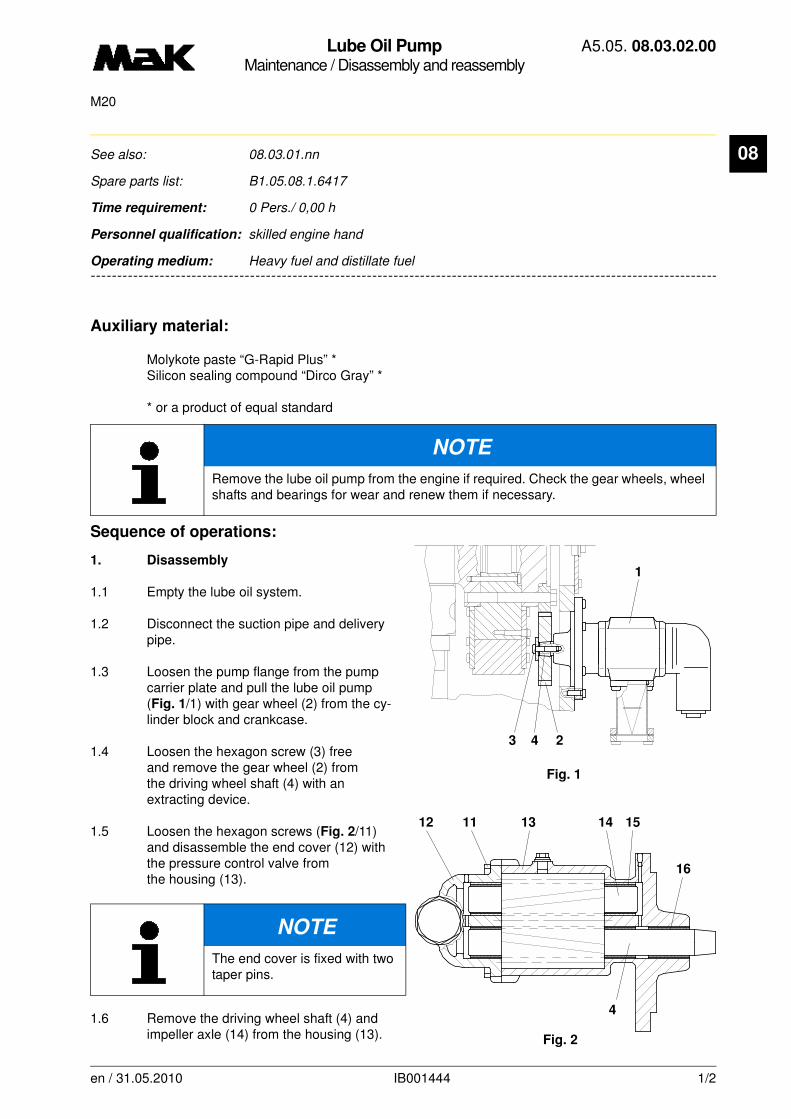
Lube Oil PumpMaintenance / Disassembly and reassembly
A5.05. 08.03.02.00
M20
08
-------
See also: 08.03.01.nn
Spare parts list: B1.05.08.1.6417
Time requirement: 0 Pers./ 0,00 h
Personnel qualification: skilled engine hand
-------------------------------------------------------------------------------------------------------------------------
Operating medium: Heavy fuel and distillate fuel
Auxiliary material:
Molykote paste “G-Rapid Plus” *Silicon sealing compound “Dirco Gray” *
* or a product of equal standard
Sequence of operations:
1. Disassembly
1.1 Empty the lube oil system.
1.2 Disconnect the suction pipe and delivery pipe.
1.3 Loosen the pump flange from the pump carrier plate and pull the lube oil pump (Fig. 1/1) with gear wheel (2) from the cy-linder block and crankcase.
1.4 Loosen the hexagon screw (3) free and remove the gear wheel (2) from the driving wheel shaft (4) with an extracting device.
1.5 Loosen the hexagon screws (Fig. 2/11) and disassemble the end cover (12) with the pressure control valve from the housing (13).
1.6 Remove the driving wheel shaft (4) and impeller axle (14) from the housing (13).
NOTE
Remove the lube oil pump from the engine if required. Check the gear wheels, wheel shafts and bearings for wear and renew them if necessary.
NOTE
The end cover is fixed with two taper pins.
Fig. 1
3 4 2
1
Fig. 2
12 11 13 14 15
16
4
en / 31.05.2010 IB001444 1/2
Lube Oil PumpMaintenance / Disassembly and reassembly
A5.05. 08.03.02.00
M20
08
1.7 Check the tooth surfaces for wear (pitting, cross bearing, disintegrations).1.8 Check the bearing bushes (Fig. 2/15 and 16), driving wheel shaft ends and impeller axle ends for wear and renew them if required with original MaK spare parts.
2. Reassembly
2.1 Mount the lube oil pump in reverse order.
2.2 Check the contact reflection between gear wheel cone and drive shaft cone by spot-grinding. The uniformly distributed contact reflection must be offset to the thicker end.
2.3 Heat up the gear wheel (Fig. 1/2) to approx. 150 °C in the oil bath and shrink it on the driving wheel shaft (4) (The conical surfaces are free from grease and dry).
2.4 Grease the thread and contact surface of the hexagon screw (3) and the washer with the Molykote paste “G-Rapid Plus” and tighten it with a torque of
M = 60 Nm.
2.5 Insert the lube oil pump (1) with gear wheel carefully in cylinder block and crankcase (2) (the tooth surfaces of the driving gear wheels must mesh into each other) and mount it at the pump carrier plate with sealing compound.
2.6 Connect the suction pipe and delivery pipe with new gaskets.
2.7 Check the lube oil supply of the gear wheels.
2.8 Start up the lube oil pump (1) and vent the system. Check for tightness.
NOTE
Undercool new bushes before the installation.
en / 31.05.2010 IB001444 2/2
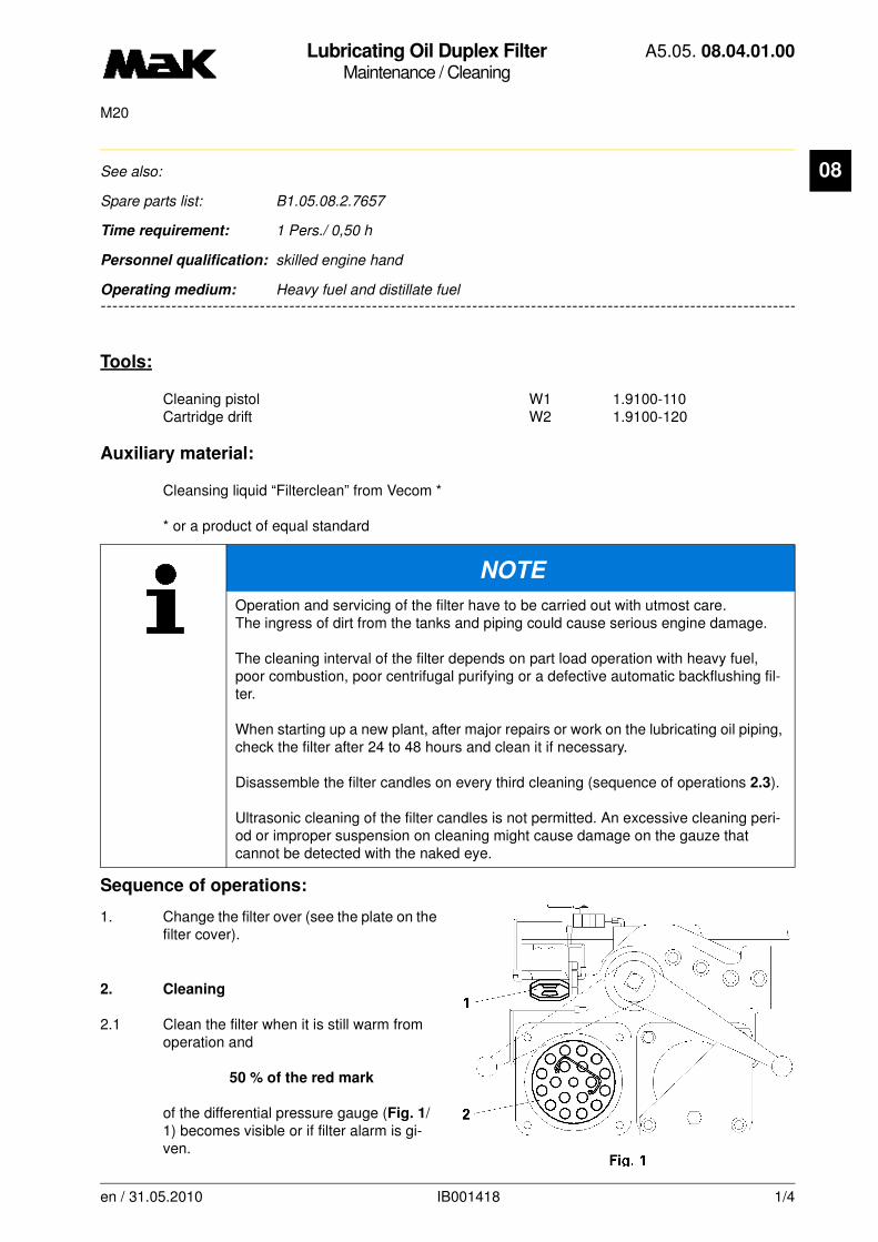
Lubricating Oil Duplex FilterMaintenance / Cleaning
A5.05. 08.04.01.00
M20
08
-------
See also:
Spare parts list: B1.05.08.2.7657
Time requirement: 1 Pers./ 0,50 h
Personnel qualification: skilled engine hand
-------------------------------------------------------------------------------------------------------------------------
Operating medium: Heavy fuel and distillate fuel
Tools:
Cleaning pistol W1 1.9100-110 Cartridge drift W2 1.9100-120
Auxiliary material:
Cleansing liquid “Filterclean” from Vecom *
* or a product of equal standard
Sequence of operations:
1. Change the filter over (see the plate on the filter cover).
2. Cleaning
2.1 Clean the filter when it is still warm from operation and
50 % of the red mark
of the differential pressure gauge (Fig. 1/1) becomes visible or if filter alarm is gi-ven.
NOTE
Operation and servicing of the filter have to be carried out with utmost care. The ingress of dirt from the tanks and piping could cause serious engine damage.
The cleaning interval of the filter depends on part load operation with heavy fuel, poor combustion, poor centrifugal purifying or a defective automatic backflushing fil-ter.
When starting up a new plant, after major repairs or work on the lubricating oil piping, check the filter after 24 to 48 hours and clean it if necessary.
Disassemble the filter candles on every third cleaning (sequence of operations 2.3).
Ultrasonic cleaning of the filter candles is not permitted. An excessive cleaning peri-od or improper suspension on cleaning might cause damage on the gauze that cannot be detected with the naked eye.
en / 31.05.2010 IB001418 1/4

Lubricating Oil Duplex FilterMaintenance / Cleaning
A5.05. 08.04.01.00
M20
08
2.2 Filter cleaning with mounted filtercandles.
2.2.1 Remove the cover from the filter chamber that has been cut out. Open the sludge drain and drain the contaminated liquid.
2.2.2 Remove the filter element.
2.2.3 Connect the cleaning pistol (Fig. 2/W1) to the compressed air supply and impinge the working pressure(6 -max. 10 bar).
2.2.4 Shift the spouting guard (13) to the stop at the pistol nozzle, put it into the cartridge opening and hold it tight. Pull the trigger of the cleaning pistol and introduce the nozzle gradually down to the bottom of each filter candles (14).
2.2.5 Fit the cover. Renew the gasket if necessary.
2.2.6 Fill the filter chamber and vent it (see the plate on the filter cover).
2.3 Filter cleaning with removed filter cand-
les (every third cleaning).
2.3.1 Empty the filter chamber by opening the sludge drain.
2.3.2 Remove the filter element.
2.3.3 Flush the filter chamber with gas oil.
WARNING
Depressurize the filter chamber!
en / 31.05.2010 IB001418 2/4
Lubricating Oil Duplex FilterMaintenance / Cleaning
A5.05. 08.04.01.00
M20
08
2.3.4 Put the filter element in a suitable cleansing liquid. The cleansing liquid must only reach up tothe bottom edge of the element plate (Fig. 3/2) so that no contaminated liquid can enter
into the filter candles (14) from the top. The top area of the gauze must be visible in the
filter candles. Soaking time as required by the suppliers of the cleanser, but maximum 4 hours.
2.3.5 Take the filter element out of cleansing liquid and blow through filter candles (14) with compressed air (Fig. 2/W1) (sequence of operations 2.2.4). Air pressure max. 10 bar.
2.3.6 Put the filter element again in clean cleansing liquid, allow to drip dry and blow through with com-pressed air (W1). Turn filter element upside down, so that the cleansing liquid can drain off.
2.3.7 Check the filter candles occasionally for damage (sequence of operations 2.4).
2.3.8 Put the filter element in the chamber, fit the cover and renew the gasket if necessary.
2.3.9 Fill the filter chamber and vent it (see the plate on the filter cover).
2.4 Cleaning the filter candles in the case of heavy soiling.
2.4.1 Soak the filter element in cleansing liquid (max. 4 hours).
2.4.2 Disconnect the base plate and carefully remove the protective shell from the filter element.
2.4.3 Remove the filter candles (14) with the drift (Fig. 3/W2) downwards and tilt them out. Remove
the O-ring (25) between the filter candles and the element plate (2), because O-rings must
not have contact with the cleansing liquid.
2.4.4 Inspect the filter candles and renew them in the case of damage and/or heavy folding of
the gauze.
2.4.5 Connect the cleaning pistol (Fig. 2/W1) to the compressed air supply. Air pressure max. 10 bar.
NOTE
In the case of heavy soiling of the filter element (paint spots, incrustation, tar deposits, fibers, chips), remove filter candles and clean them individually.
CAUTION
The damage on only one filter candles means malfunction of the whole element. Do not put the removed filter candles one upon another; this might damage the gauze.
en / 31.05.2010 IB001418 3/4

Lubricating Oil Duplex FilterMaintenance / Cleaning
A5.05. 08.04.01.00
M20
08
2.4.6 Introduce the pistol into the cartridge, pull the trigger and move down to the bottom of each filter
candles.
2.4.7 Remove sticking dirt with a soft brush.
2.4.8 Rinse the filter candles in clean cleansing liquid, blow through with air and allow them to dry with the opening facing downwards.
2.4.9 Put a strong light behind the gauze and check the cleaning operation. Repeat it if necessary.
2.4.10 Fit the filter candles in reverse order as described under 2.4.3. The O-ring between element plate and filter candles must be free from cracks and deformation.
3. Check the gasket between element plate and filter housing and renew it if necessary.
4. Fit the element in the filter chamber.
5. Fit the cover (renew the gasket).
6. Fill the filter chamber and vent it (see the plate on the filter cover).
NOTE
If possible, clean the filter elements from the ouside with a high-pressure cleaner. Working pressure of the high-pressure cleaner max. 60 bar. Cleansing agent: Warm water or water with cleansing liquid.
CAUTION
When cleaning with the high-pressure cleaner, be careful not to hold the nozzle too close to the gauze in order to avoid damage and/or displacement of the gauze wires.
en / 31.05.2010 IB001418 4/4
Oil pressure control valveMaintenance / Adjust
A5.05. 08.05.01.00
15000M20
08
-------
See also: 08.03.02.nn
Spare parts list: B1.05.08.2.6417
Time requirement: 1 Pers./ 1,00 h
Personnel qualification: skilled engine hand
-------------------------------------------------------------------------------------------------------------------------
Operating medium: Heavy fuel and distillate fuel
Maintenance:
Disassembly and adjustment of the oil pressure control valve every 15,000 h
Sequence of operations:
1. Disassembly
1.1 Loosen the cheese head screws (8) evenly to relieve the pressure spring (3).
1.2 Remove and dismantle the control valve (1).
1.2.1 Remove protective cap (30).
1.2.2 Loosen the hexagon nut (18) and completely unscrew the spindle (19) by turning it counter-clockwise and remove it together with the ball (16).
1.2.3 Loosen the screw connection (17) and remove it together with the sealing ring (14) and bush (10).
1.2.4 Remove the locking ring (9) and take out the piston (11) with washer (15) and pressure spring (13).
NOTE
Disassembly of the pressure control valve during the repair interval is only necessary if the necessary lubricating oil pressure can no longer be set by adjusting the initial tension of the spring. The lubricating oil pressure (see A1.05, engine data) is only allowed to be adjusted at the nominal engine speed (A1.10) and at the specified lubri-cating oil temperature (see A1.06).
WARNING
Pay attention to the tension of the pressure spring (Fig. 1/3) on the control valve (1)!
WARNING
Pay attention to the tension of the pressure spring (13) on the screwed connection (17)!
en / 31.05.2010 IB024704 1/3
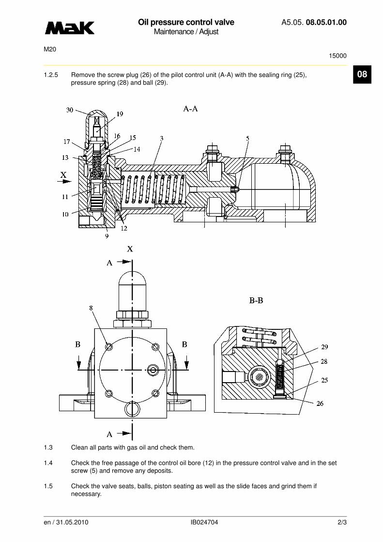
Oil pressure control valveMaintenance / Adjust
A5.05. 08.05.01.00
15000M20
08
1.2.5 Remove the screw plug (26) of the pilot control unit (A-A) with the sealing ring (25), pressure spring (28) and ball (29).1.3 Clean all parts with gas oil and check them.
1.4 Check the free passage of the control oil bore (12) in the pressure control valve and in the set screw (5) and remove any deposits.
1.5 Check the valve seats, balls, piston seating as well as the slide faces and grind them if necessary.
en / 31.05.2010 IB024704 2/3
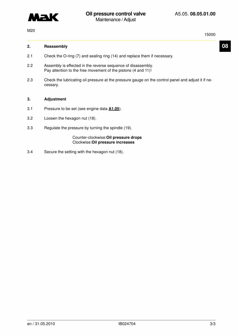
Oil pressure control valveMaintenance / Adjust
A5.05. 08.05.01.00
15000M20
08
2. Reassembly2.1 Check the O-ring (7) and sealing ring (14) and replace them if necessary.
2.2 Assembly is effected in the reverse sequence of disassembly.Pay attention to the free movement of the pistons (4 and 11)!
2.3 Check the lubricating oil pressure at the pressure gauge on the control panel and adjust it if ne-cessary.
3. Adjustment
3.1 Pressure to be set (see engine data A1.05).
3.2 Loosen the hexagon nut (18).
3.3 Regulate the pressure by turning the spindle (19).
Counter-clockwise:Oil pressure drops
Clockwise:Oil pressure increases
3.4 Secure the setting with the hexagon nut (18).
en / 31.05.2010 IB024704 3/3

Oil pressure control valveMaintenance / Adjust
A5.05. 08.05.01.01
15000M20/M25/M32/M43
08
-------
See also:
Spare parts list: B1.05.08.n.7810
Time requirement: 1 Pers./ 1,00 h
Personnel qualification: skilled engine hand
-------------------------------------------------------------------------------------------------------------------------Operating medium: Heavy fuel and distillate fuel
Maintenance:
Disassembly and adjustment of the oil pressure control valve every 15,000 h
Sequence of operations:
1. Disassembly
1.1 Loosen the cheese head screws (8) evenly to relieve the pressure spring (3).
1.2 Remove and dismantle the control valve (1).
1.2.1 Loosen the hexagon nut (18) and completely unscrew the spindle (19) by turning it counter-clockwise and remove it together with the ball (16).
NOTE
Disassembly of the pressure control valve during the repair interval is only necessary if the necessary lubricating oil pressure can no longer be set by adjusting the initial tension of the spring.
The lubricating oil pressure is only allowed to be adjusted at the nominal engine speed and at the specified lubricating oil temperature, see engine documentation, chapter "Technical Engine Data".
CAUTION
Pay attention to the tension of the pressure spring (Fig. 1/3) on the control valve (1)!
CAUTION
Pay attention to the tension of the pressure spring (13) on the screwed connection (17)!
en / 26.11.2010 IB022593 1/3
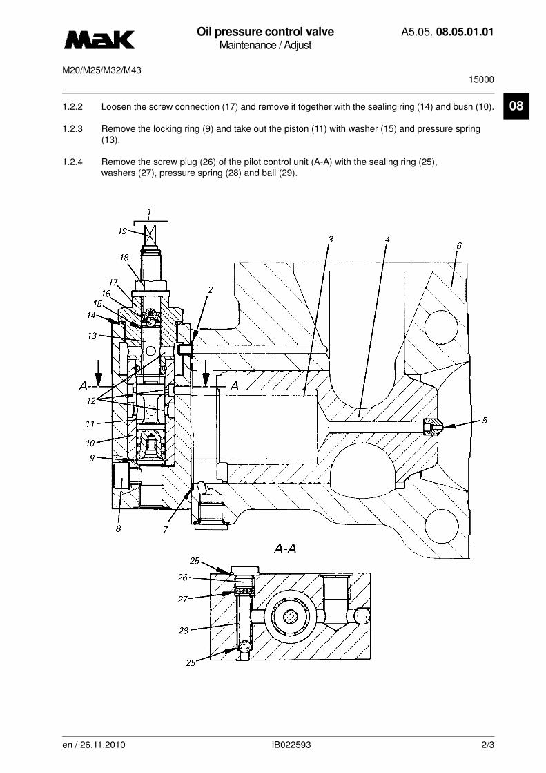
Oil pressure control valveMaintenance / Adjust
A5.05. 08.05.01.01
15000M20/M25/M32/M43
08
1.2.2 Loosen the screw connection (17) and remove it together with the sealing ring (14) and bush (10).1.2.3 Remove the locking ring (9) and take out the piston (11) with washer (15) and pressure spring (13).
1.2.4 Remove the screw plug (26) of the pilot control unit (A-A) with the sealing ring (25), washers (27), pressure spring (28) and ball (29).
en / 26.11.2010 IB022593 2/3

Oil pressure control valveMaintenance / Adjust
A5.05. 08.05.01.01
15000M20/M25/M32/M43
08
1.3 Clean all parts with gas oil and check them.1.4 Check the free passage of the control oil bore (12) in the pressure control valve and in the set screw (5) and remove any deposits.
1.5 Check the valve seats, balls, piston seating as well as the slide faces and grind them if necessary.
2. Reassembly
2.1 Check the O-rings (2 and 7) and sealing ring (14) and replace them if necessary.
2.2 Assembly is effected in the reverse sequence of disassembly.Pay attention to the free movement of the pistons (4 and 11)!
2.3 Check the lubricating oil pressure at the pressure gauge on the control panel and adjust it if ne-cessary.
3. Adjustment
3.1 Pressure to be set, see engine documentation, chapter "Technical Engine Data".
3.2 Loosen the hexagon nut (18).
Regulate the pressure by turning the spindle (19).
Counter-clockwise: Oil pressure drops
Clockwise: Oil pressure increases
3.3 Secure the setting with the hexagon nut (18).
en / 26.11.2010 IB022593 3/3
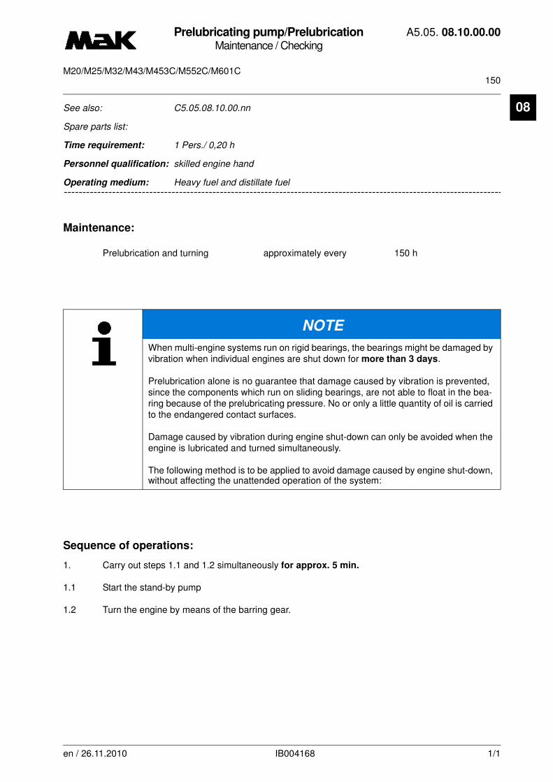
Prelubricating pump/PrelubricationMaintenance / Checking
A5.05. 08.10.00.00
150M20/M25/M32/M43/M453C/M552C/M601C
en / 26.11.2010 IB004168 1/1
08See also: C5.05.08.10.00.nn
Spare parts list:
Time requirement: 1 Pers./ 0,20 h
Personnel qualification: skilled engine hand
--------------------------------------------------------------------------------------------------------------------------------Operating medium: Heavy fuel and distillate fuel
Maintenance:
Prelubrication and turning approximately every 150 h
Sequence of operations:
1. Carry out steps 1.1 and 1.2 simultaneously for approx. 5 min.
1.1 Start the stand-by pump
1.2 Turn the engine by means of the barring gear.
NOTE
When multi-engine systems run on rigid bearings, the bearings might be damaged by vibration when individual engines are shut down for more than 3 days.
Prelubrication alone is no guarantee that damage caused by vibration is prevented, since the components which run on sliding bearings, are not able to float in the bea-ring because of the prelubricating pressure. No or only a little quantity of oil is carried to the endangered contact surfaces.
Damage caused by vibration during engine shut-down can only be avoided when the engine is lubricated and turned simultaneously.
The following method is to be applied to avoid damage caused by engine shut-down, without affecting the unattended operation of the system:
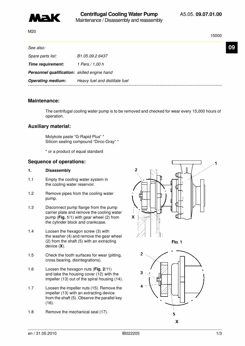
Centrifugal Cooling Water PumpMaintenance / Disassembly and reassembly
A5.05. 09.07.01.00
15000M20
09
-------
See also:
Spare parts list: B1.05.09.2.6437
Time requirement: 1 Pers./ 1,00 h
Personnel qualification: skilled engine hand
-------------------------------------------------------------------------------------------------------------------------
Operating medium: Heavy fuel and distillate fuel
Maintenance:
The centrifugal cooling water pump is to be removed and checked for wear every 15,000 hours of operation.
Auxiliary material:
Molykote paste “G-Rapid Plus” * Silicon sealing compound “Dirco-Gray” *
* or a product of equal standard
Sequence of operations:
1. Disassembly
1.1 Empty the cooling water system in the cooling water reservoir.
1.2 Remove pipes from the cooling water pump.
1.3 Disconnect pump flange from the pump carrier plate and remove the cooling water pump (Fig. 1/1) with gear wheel (2) from the cylinder block and crankcase.
1.4 Loosen the hexagon screw (3) with the washer (4) and remove the gear wheel (2) from the shaft (5) with an extracting device (X).
1.5 Check the tooth surfaces for wear (pitting, cross bearing, disintegrations).
1.6 Loosen the hexagon nuts (Fig. 2/11) and take the housing cover (12) with the impeller (13) out of the spiral housing (14).
1.7 Loosen the impeller nuts (15). Remove the impeller (13) with an extracting device from the shaft (5). Observe the parallel key (16).
1.8 Remove the mechanical seal (17).
en / 31.05.2010 IB022205 1/3

Centrifugal Cooling Water PumpMaintenance / Disassembly and reassembly
A5.05. 09.07.01.00
15000M20
09
1.9 Loosen the hexagon screws (Fig. 2/18) and remove the housing cover (12) from the bearing car-rier (19).1.10 Loosen flat head screw (28).
1.11 Remove cover (26) with sealing ring (27).
1.12 Remove “Nilos“ lock ring (20).
1.13 Force shaft (5) and grooved ball bearing (22) out of bearing flange (19) with a suitable tool..
2. Inspection
2.1 Inspect the impeller (13) visually and renew it in the case of heavy cavitation.
2.2 Check the ball bearings for freedom of movement, wear, corrosion, ball disintegrations and renew them if necessary.
2.3 Check the pressure compensating hole (24) and leaking liquid discharge (25) for free passage.
3. Reassembly
3.1 The reassembly is made in reverse order observing the following:
3.2 Renew all gaskets of the housings and mechanical seal (17).
3.3 Before mounting the impeller (13), check contact reflection between impeller cone and shaft cone by spot-grinding. (Min. 60 % of profile bearing length distributed uniformly over the cone.)
27
19 28
22
18
11
15
16
17
24
1412
20
25
5
132622
Fig. 2
en / 31.05.2010 IB022205 2/3
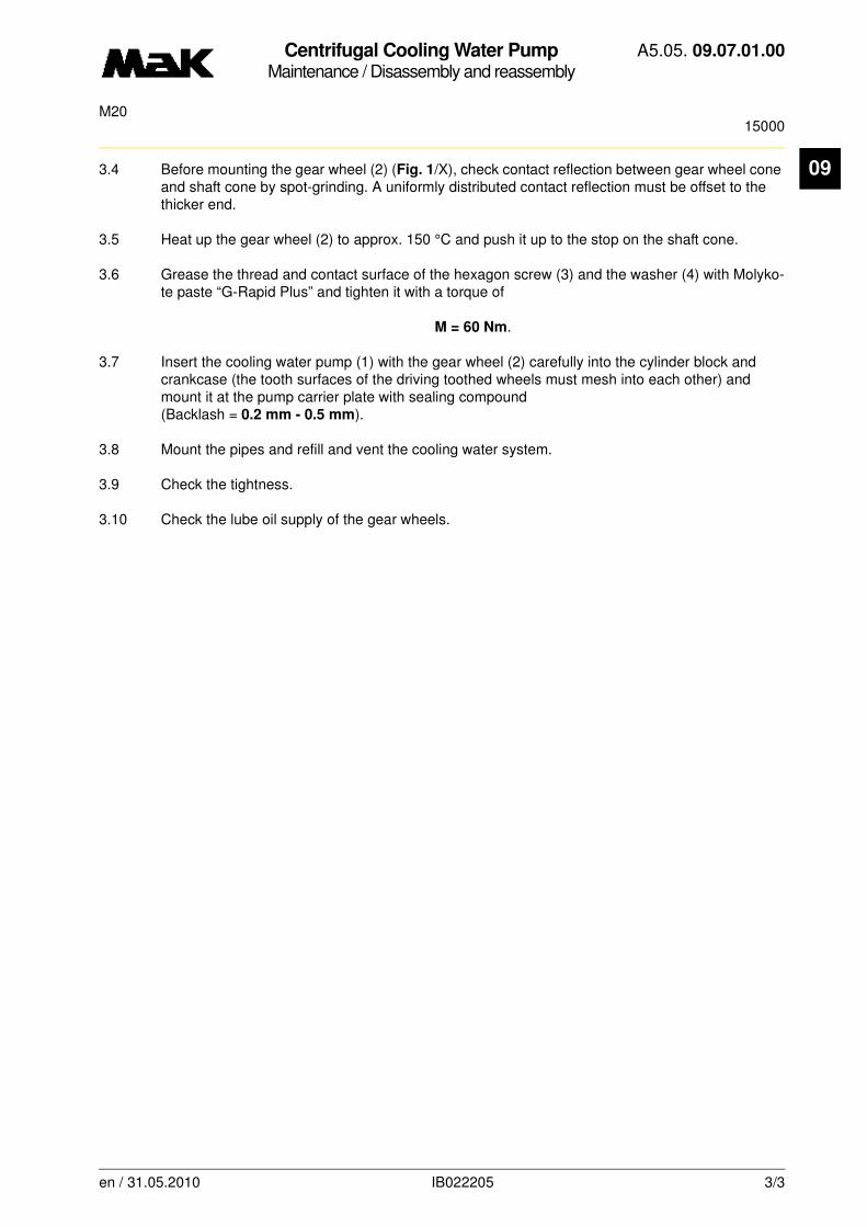
Centrifugal Cooling Water PumpMaintenance / Disassembly and reassembly
A5.05. 09.07.01.00
15000M20
09
3.4 Before mounting the gear wheel (2) (Fig. 1/X), check contact reflection between gear wheel cone and shaft cone by spot-grinding. A uniformly distributed contact reflection must be offset to the thicker end.3.5 Heat up the gear wheel (2) to approx. 150 °C and push it up to the stop on the shaft cone.
3.6 Grease the thread and contact surface of the hexagon screw (3) and the washer (4) with Molyko-te paste “G-Rapid Plus” and tighten it with a torque of
M = 60 Nm.
3.7 Insert the cooling water pump (1) with the gear wheel (2) carefully into the cylinder block and crankcase (the tooth surfaces of the driving toothed wheels must mesh into each other) and mount it at the pump carrier plate with sealing compound (Backlash = 0.2 mm - 0.5 mm).
3.8 Mount the pipes and refill and vent the cooling water system.
3.9 Check the tightness.
3.10 Check the lube oil supply of the gear wheels.
en / 31.05.2010 IB022205 3/3

Centrifugal Cooling Water PumpMaintenance / Disassembly and reassembly
A5.05. 09.07.01.01
15000M20
09
-------
See also: -
Spare parts list: B1.05.09.2.6437
Time requirement: 1 Pers./ 1,00 h
Personnel qualification: skilled engine hand
-------------------------------------------------------------------------------------------------------------------------
Operating medium: Heavy fuel and distillate fuel
Maintenance:
The centrifugal cooling water pump is to be removed and checked for wear every 15,000 hours of operation.
Auxiliary material:
Molykote paste “G-Rapid Plus” * Silicon sealing compound “Dirco-Gray” *
* or a product of equal standard
Sequence of operations:
1. Disassembly
1.1 Empty the cooling water system in the cooling water reservoir.
1.2 Remove pipes from the cooling water pump.
1.3 Disconnect pump flange from the pump carrier plate and remove the cooling water pump (Fig. 1/1) with gear wheel (2) from the cylinder block and crankcase.
1.4 Loosen the hexagon screw (3) with the washer (4) and remove the gear wheel (2) from the shaft (5) with an extracting device (X).
1.5 Check the tooth surfaces for wear (pitting, cross bearing, disintegrations).
1.6 Loosen the hexagon nuts (Fig. 2/11) and take the housing cover (12) with the impeller (13) out of the spiral housing (14).
1.7 Loosen the impeller nuts (15). Remove the impeller (13) with an extracting device from the shaft (5). Observe the parallel key (16).
1.8 Remove the mechanical seal (17).
en / 31.05.2010 IB022224 1/3
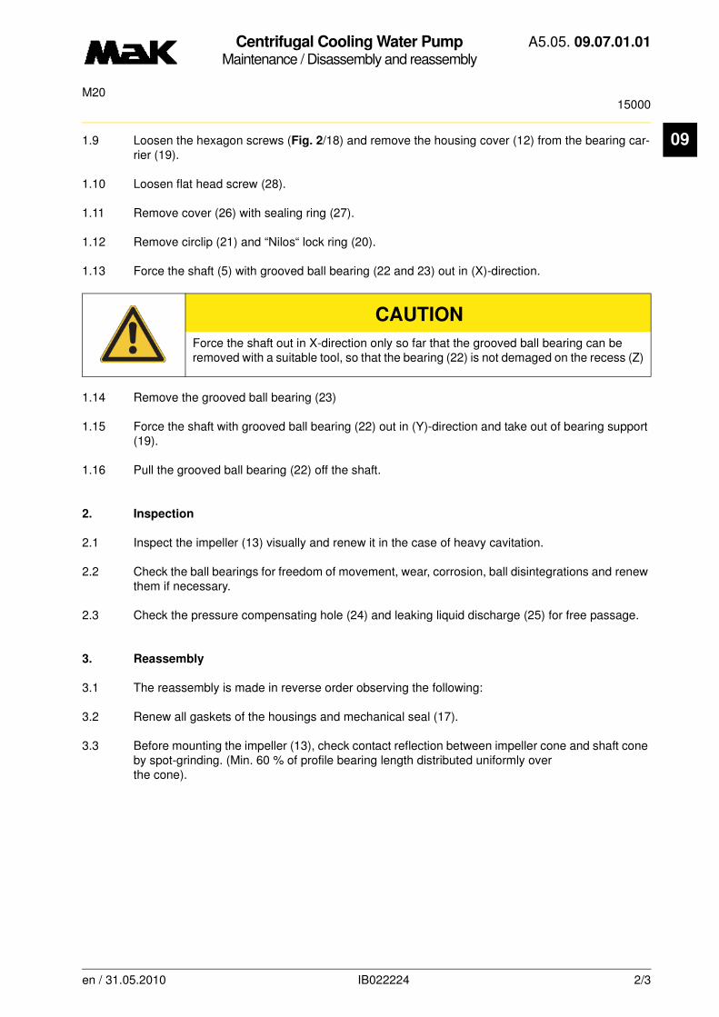
Centrifugal Cooling Water PumpMaintenance / Disassembly and reassembly
A5.05. 09.07.01.01
15000M20
09
1.9 Loosen the hexagon screws (Fig. 2/18) and remove the housing cover (12) from the bearing car-rier (19).1.10 Loosen flat head screw (28).
1.11 Remove cover (26) with sealing ring (27).
1.12 Remove circlip (21) and “Nilos“ lock ring (20).
1.13 Force the shaft (5) with grooved ball bearing (22 and 23) out in (X)-direction.
1.14 Remove the grooved ball bearing (23)
1.15 Force the shaft with grooved ball bearing (22) out in (Y)-direction and take out of bearing support (19).
1.16 Pull the grooved ball bearing (22) off the shaft.
2. Inspection
2.1 Inspect the impeller (13) visually and renew it in the case of heavy cavitation.
2.2 Check the ball bearings for freedom of movement, wear, corrosion, ball disintegrations and renew them if necessary.
2.3 Check the pressure compensating hole (24) and leaking liquid discharge (25) for free passage.
3. Reassembly
3.1 The reassembly is made in reverse order observing the following:
3.2 Renew all gaskets of the housings and mechanical seal (17).
3.3 Before mounting the impeller (13), check contact reflection between impeller cone and shaft cone by spot-grinding. (Min. 60 % of profile bearing length distributed uniformly overthe cone).
CAUTION
Force the shaft out in X-direction only so far that the grooved ball bearing can be removed with a suitable tool, so that the bearing (22) is not demaged on the recess (Z)
en / 31.05.2010 IB022224 2/3

Centrifugal Cooling Water PumpMaintenance / Disassembly and reassembly
A5.05. 09.07.01.01
15000M20
09
.3.4 Before mounting the gear wheel (2) (Fig. 1/X), check contact reflection between gear wheel cone and shaft cone by spot-grinding. A uniformly distributed contact reflection must be offset to the thicker end.
3.5 Heat up the gear wheel (2) to approx. 150 °C and push it up to the stop on the shaft cone.
3.6 Grease the thread and contact surface of the hexagon screw (3) and the washer (4) with Molyko-te paste “G-Rapid Plus” and tighten it with a torque of
M = 60 Nm.
3.7 Insert the cooling water pump (1) with the gear wheel (2) carefully into the cylinder block and crankcase (the tooth surfaces of the driving toothed wheels must mesh into each other) and mount it at the pump carrier plate with sealing compound (Backlash = 0.2 mm - 0.5 mm).
3.8 Mount the pipes and refill and vent the cooling water system.
3.9 Check the tightness.
3.10 Check the lube oil supply of the gear wheels.
Fig. 2
19 28
27
Z
20 22
22
11
15
16
17
24
25
21
1412
5
1326
18
Y X
en / 31.05.2010 IB022224 3/3
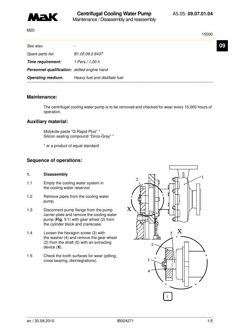
Centrifugal Cooling Water PumpMaintenance / Disassembly and reassembly
A5.05. 09.07.01.04
15000M20
09
-------
See also: -
Spare parts list: B1.05.09.2.6437
Time requirement: 1 Pers./ 1,00 h
Personnel qualification: skilled engine hand
-------------------------------------------------------------------------------------------------------------------------
Operating medium: Heavy fuel and distillate fuel
Maintenance:
The centrifugal cooling water pump is to be removed and checked for wear every 15,000 hours of operation.
Auxiliary material:
Molykote paste “G-Rapid Plus” * Silicon sealing compound “Dirco-Gray” *
* or a product of equal standard
Sequence of operations:
1. Disassembly
1.1 Empty the cooling water system in the cooling water reservoir.
1.2 Remove pipes from the cooling water pump.
1.3 Disconnect pump flange from the pump carrier plate and remove the cooling water pump (Fig. 1/1) with gear wheel (2) from the cylinder block and crankcase.
1.4 Loosen the hexagon screw (3) with the washer (4) and remove the gear wheel (2) from the shaft (5) with an extracting device (X).
1.5 Check the tooth surfaces for wear (pitting, cross bearing, disintegrations).
en / 30.09.2010 IB024271 1/5
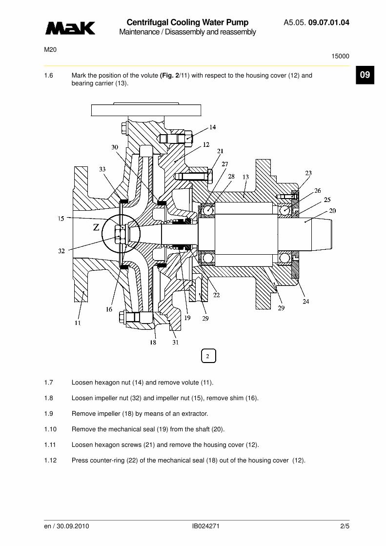
Centrifugal Cooling Water PumpMaintenance / Disassembly and reassembly
A5.05. 09.07.01.04
15000M20
09
1.6 Mark the position of the volute (Fig. 2/11) with respect to the housing cover (12) and bearing carrier (13).1.7 Loosen hexagon nut (14) and remove volute (11).
1.8 Loosen impeller nut (32) and impeller nut (15), remove shim (16).
1.9 Remove impeller (18) by means of an extractor.
1.10 Remove the mechanical seal (19) from the shaft (20).
1.11 Loosen hexagon screws (21) and remove the housing cover (12).
1.12 Press counter-ring (22) of the mechanical seal (18) out of the housing cover (12).
en / 30.09.2010 IB024271 2/5
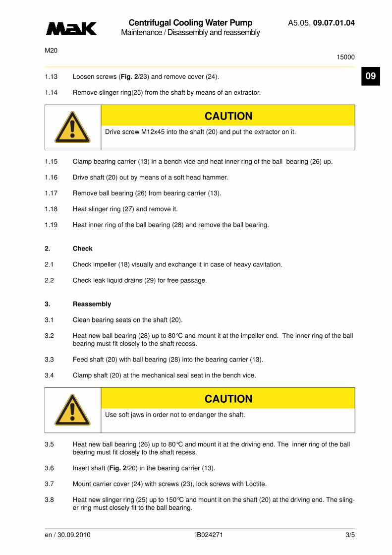
Centrifugal Cooling Water PumpMaintenance / Disassembly and reassembly
A5.05. 09.07.01.04
15000M20
09
1.13 Loosen screws (Fig. 2/23) and remove cover (24).1.14 Remove slinger ring(25) from the shaft by means of an extractor.
1.15 Clamp bearing carrier (13) in a bench vice and heat inner ring of the ball bearing (26) up.
1.16 Drive shaft (20) out by means of a soft head hammer.
1.17 Remove ball bearing (26) from bearing carrier (13).
1.18 Heat slinger ring (27) and remove it.
1.19 Heat inner ring of the ball bearing (28) and remove the ball bearing.
2. Check
2.1 Check impeller (18) visually and exchange it in case of heavy cavitation.
2.2 Check leak liquid drains (29) for free passage.
3. Reassembly
3.1 Clean bearing seats on the shaft (20).
3.2 Heat new ball bearing (28) up to 80°C and mount it at the impeller end. The inner ring of the ball bearing must fit closely to the shaft recess.
3.3 Feed shaft (20) with ball bearing (28) into the bearing carrier (13).
3.4 Clamp shaft (20) at the mechanical seal seat in the bench vice.
3.5 Heat new ball bearing (26) up to 80°C and mount it at the driving end. The inner ring of the ball bearing must fit closely to the shaft recess.
3.6 Insert shaft (Fig. 2/20) in the bearing carrier (13).
3.7 Mount carrier cover (24) with screws (23), lock screws with Loctite.
3.8 Heat new slinger ring (25) up to 150°C and mount it on the shaft (20) at the driving end. The sling-er ring must closely fit to the ball bearing.
CAUTION
Drive screw M12x45 into the shaft (20) and put the extractor on it.
CAUTION
Use soft jaws in order not to endanger the shaft.
en / 30.09.2010 IB024271 3/5

Centrifugal Cooling Water PumpMaintenance / Disassembly and reassembly
A5.05. 09.07.01.04
15000M20
09
3.9 Heat new slinger ring (Fig. 2/27) up to 150°C and mount it on the shaft (20) at the impeller end. The slinger ring must fit closely to the ball bearing.3.10 Insert new split ring (30) in the housing cover (12).
3.11 Insert counter-ring (22) of the mechanical seal in the housing cover (12).
3.12 Mount housing cover (12) on the bearing carrier in the correct position.
3.13 Before mounting the impeller (18) check the bearing pattern between impeller cone and shaft cone by spot-grinding. (Bearing portion of at least 60 % uniformly distributed on the cone).
3.14 Mount mechanical seal (19).
3.15 Hest impeller(18) up (max. 200 °C) and slide it on the shaft.
3.16 Reference dimension (Z)
d = 1.8 ± 0,1 mm
3.17 Mount the shim (16) , recess shows intothe direction of the impeller.
3.18 Mount the nut (15) nd tighten it with
M = 90 Nm
3.19 Lock the nut (16) with the 2nd nut (32)and secure the nuts with loctite.
3.20 Insert new split ring (33) in the volute (11).
3.21 Put flat gasket (31) into the volute (11).
3.22 Mount volute (11) on the housing cover (12) in the correct position.
3.23 Before mounting the flywheel (2) (fig. 1/x) check bearing pattern between gear wheel cone and shaft cone by spot-grinding. A uniformly distributed bearing pattern must be shifted to the thicker end.
CAUTION
Lock impeller nuts with Loctite
en / 30.09.2010 IB024271 4/5
Centrifugal Cooling Water PumpMaintenance / Disassembly and reassembly
A5.05. 09.07.01.04
15000M20
09
3.24 Heat gear wheel (2) up to 150°C and place it on the shaft cone up to the limit stop. (Cone surface grease-free and dry).3.25 Coat thread and contact surface of the hexagon screw (3) and washer (4) with Molykote paste "G-Rapid Plus" and tighten with a torque of
M = 60 Nm
3.26 Insert cooling water pump (Fig. 1/1) with gear wheel (2) carefully into the engine block (gear flanks of the driving gear wheels must be meshing, backlash must be palpable) and mount it at the pump carrier plate with sealing compound.
3.27 Mount the pipes and refill and vent the cooling water system.
3.28 Check the tightness.
3.29 Check the lube oil supply of the gear wheels.
en / 30.09.2010 IB024271 5/5
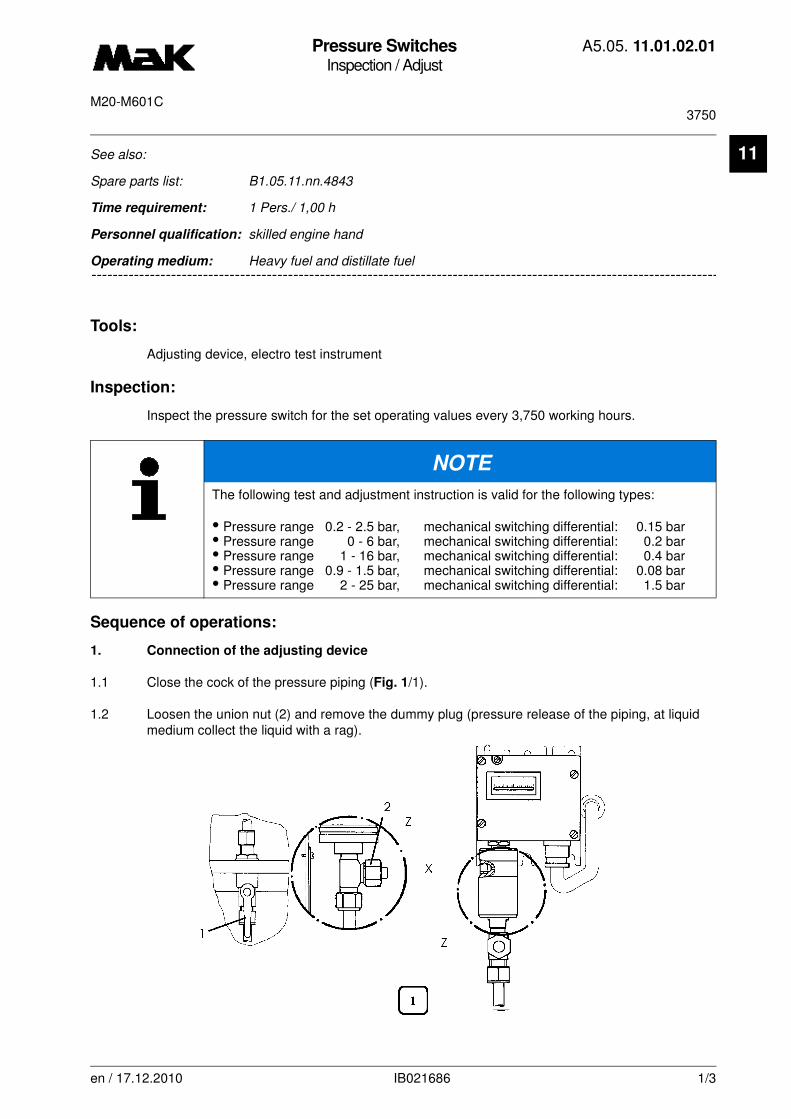
Pressure SwitchesInspection / Adjust
A5.05. 11.01.02.01
3750M20-M601C
11
-------
See also:
Spare parts list: B1.05.11.nn.4843
Time requirement: 1 Pers./ 1,00 h
Personnel qualification: skilled engine hand
-------------------------------------------------------------------------------------------------------------------------Operating medium: Heavy fuel and distillate fuel
Tools:
Adjusting device, electro test instrument
Inspection:
Inspect the pressure switch for the set operating values every 3,750 working hours.
Sequence of operations:
1. Connection of the adjusting device
1.1 Close the cock of the pressure piping (Fig. 1/1).
1.2 Loosen the union nut (2) and remove the dummy plug (pressure release of the piping, at liquid medium collect the liquid with a rag).
NOTE
The following test and adjustment instruction is valid for the following types:
• Pressure range 0.2 - 2.5 bar, mechanical switching differential: 0.15 bar• Pressure range 0 - 6 bar, mechanical switching differential: 0.2 bar• Pressure range 1 - 16 bar, mechanical switching differential: 0.4 bar• Pressure range 0.9 - 1.5 bar, mechanical switching differential: 0.08 bar• Pressure range 2 - 25 bar, mechanical switching differential: 1.5 bar
en / 17.12.2010 IB021686 1/3

Pressure SwitchesInspection / Adjust
A5.05. 11.01.02.01
3750M20-M601C
11
1.3 Connect the hose (with union nut and cutting) with the adju-sting device (Fig. 2).
2. Inspection of the set values
2.1 Ventilate the pressure switch via the adjustment device.
2.2 Inspect the pressure control via the pressure gauge (of the device) and simultaneously the switch point at the instrument or alarm unit for coincidence of the switch point with the set value.
2.3 At any deviation correct the adjustment due to item 3.
2.4 Deaerate the pressure switch slightly and simultaneously check the switch point via the test in-strument. Inspect the displayed switch difference.
CAUTION
When loosen/thighten the union nut directly located at the pressure joint of the pres-sure switch, it should be simultaneously counter acted at the key faces of the pressu-re joint.
CAUTION
For setting the differential pressure switch, the adjusting device must be equipped with two text connections (+, –, pressure difference) refer to view “X”.
Pressure monitor Difference pressure monitor
en / 17.12.2010 IB021686 2/3

Pressure SwitchesInspection / Adjust
A5.05. 11.01.02.01
3750M20-M601C
11
3. Correction of the adjustment (Perfor-mance with fixed switch difference)
(Fig. 3)
3.1 Remove the case cover by loosening the 4 locking screws.
3.2 Connect terminal (1 + 4) via cable with the adjusting device.
3.3 Loosen the stop screw (A).
3.4 Remove the cover aside by loosening the locking screw (B).
3.5 Set the upper or lower switching point (dif-ferential pressure switch) by means of the range spindle (C).
The lower or upper switching point (differential pressure switch) results in the fixed switching difference.
3.6 Tighten stop screw (A).
4. Removal of the adjusting device
4.1 Loosen the cable connection (terminal 1 + 4).
4.2 Loosen the connection hose of the adjusting device screw on the union nuts with plug (Fig. 1/2).
4.3 Fit the cover.
4.4 Tighten the cover of the range spindle.
4.5 Mark or lead the impected or corrected pressure switches.
NOTE
The scale accuracy is ± 2 % of the span. The instrument is in-dividually calibrated (1 - 2 on) so that no gauge inspection is necessary.
en / 17.12.2010 IB021686 3/3

Pressure SwitchesInspection / Adjust
A5.05. 11.01.03.00
3750M20
11
-------
See also:
Spare parts list: B1.05.11.2.4842
Time requirement: 1 Pers./ 0,50 h
Personnel qualification: skilled engine hand
-------------------------------------------------------------------------------------------------------------------------
Operating medium: Heavy fuel and distillate fuel
Tools:
Adjusting device, electric measuring instrument
Inspection:
Check the set operating values of the pressure switch every 3,750 operation hours.
Sequence of operations:
1. Connection of the adjusting device
1.1 Set cock of the pressure line (Fig. 1/1) to test position.
1.2 Remove plug (2) (G1/8") (depressurizing the line, catch liquid with a rag) and connect adjusting device in accordance with Fig. 2 and Fig. 3 to the test connection.
NOTE
These testing and adjusting instructions apply to the following types:Pressure range:0 -6 barSwitching difference:0.2 barPressure range:0 -16 barSwitching difference: 0.8 bar
en / 30.09.2010 IB021766 1/3

Pressure SwitchesInspection / Adjust
A5.05. 11.01.03.00
3750M20
11
1.3 Pneumatic connection (Fig. 2)10 Compressed air flange > 16 bar11 Pressure reducer12 Stop valve13 One-way restrictor14 Volume 1 l15 Precision manometer16 Pressure switch
1.4 Electric connection (Fig. 3)
Connect terminals 1, 2, 3 in the appliance plug.
2. Inspection
2.1 Vent pressure switch via adjusting device.
2.2 Check switching point via the precision manometer of the setting equipment and test lamps.
2.3 Gradually vent the pressure switch, thereby observe switching point on the precision manometer the adjusting device and test lamp (Check the indicated switching differential in accordance with measuring point list in Book C).
en / 30.09.2010 IB021766 2/3
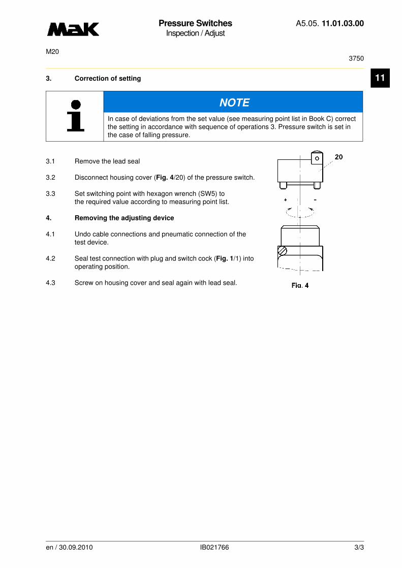
Pressure SwitchesInspection / Adjust
A5.05. 11.01.03.00
3750M20
11
3. Correction of setting3.1 Remove the lead seal
3.2 Disconnect housing cover (Fig. 4/20) of the pressure switch.
3.3 Set switching point with hexagon wrench (SW5) to the required value according to measuring point list.
4. Removing the adjusting device
4.1 Undo cable connections and pneumatic connection of the test device.
4.2 Seal test connection with plug and switch cock (Fig. 1/1) into operating position.
4.3 Screw on housing cover and seal again with lead seal.
NOTE
In case of deviations from the set value (see measuring point list in Book C) correct the setting in accordance with sequence of operations 3. Pressure switch is set in the case of falling pressure.
en / 30.09.2010 IB021766 3/3
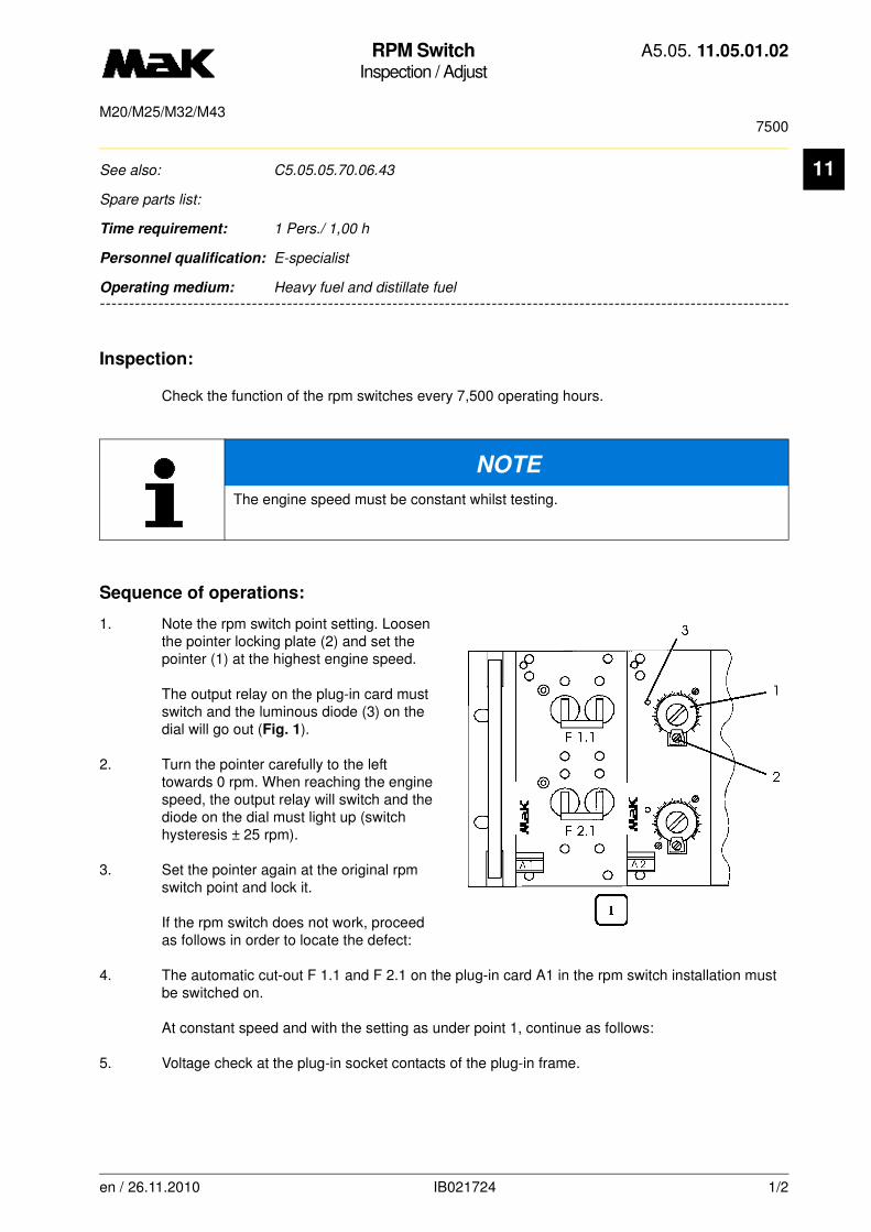
RPM SwitchInspection / Adjust
A5.05. 11.05.01.02
7500M20/M25/M32/M43
11
-------
See also: C5.05.05.70.06.43
Spare parts list:
Time requirement: 1 Pers./ 1,00 h
Personnel qualification: E-specialist
-------------------------------------------------------------------------------------------------------------------------
Operating medium: Heavy fuel and distillate fuel
Inspection:
Check the function of the rpm switches every 7,500 operating hours.
Sequence of operations:
1. Note the rpm switch point setting. Loosen the pointer locking plate (2) and set the pointer (1) at the highest engine speed.
The output relay on the plug-in card must switch and the luminous diode (3) on the dial will go out (Fig. 1).
2. Turn the pointer carefully to the left towards 0 rpm. When reaching the engine speed, the output relay will switch and the diode on the dial must light up (switch hysteresis ± 25 rpm).
3. Set the pointer again at the original rpm switch point and lock it.
If the rpm switch does not work, proceed as follows in order to locate the defect:
4. The automatic cut-out F 1.1 and F 2.1 on the plug-in card A1 in the rpm switch installation must be switched on.
At constant speed and with the setting as under point 1, continue as follows:
5. Voltage check at the plug-in socket contacts of the plug-in frame.
NOTE
The engine speed must be constant whilst testing.
en / 26.11.2010 IB021724 1/2

RPM SwitchInspection / Adjust
A5.05. 11.05.01.02
7500M20/M25/M32/M43
11
5.1 Supply (24 V DC at contact z16 and z20, contact z20 positive).5.2 PICK UP IMPULSE (dependent upon engine speed up to 1500 Hz at contact b14 and d14).
If nothing could be detected whilst checking points 4 - 6, renew the plug-in card.The engine speed must be
constant whilst testing.
NOTE
Carry out the rpm adjustment of the new plug-in card. For this see the "Engine Docu-
mentation, Chapter „Control / Regulation“, rpm switch".
en / 26.11.2010 IB021724 2/2
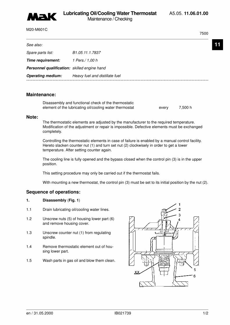
Lubricating Oil/Cooling Water ThermostatMaintenance / Checking
A5.05. 11.06.01.00
7500M20-M601C
11
-------
See also:
Spare parts list: B1.05.11.1.7837
Time requirement: 1 Pers./ 1,00 h
Personnel qualification: skilled engine hand
-------------------------------------------------------------------------------------------------------------------------
Operating medium: Heavy fuel and distillate fuel
Maintenance:
Disassembly and functional check of the thermostatic element of the lubricating oil/cooling water thermostat every 7,500 h
Note:The thermostatic elements are adjusted by the manufacturer to the required temperature. Modification of the adjustment or repair is impossible. Defective elements must be exchanged completely.
Controlling the thermostatic elements in case of failure is enabled by a manual control facility. Hereto slacken counter nut (1) and turn set nut (2) clockwisely in order to get a lower temperature. After setting counter again.
The cooling line is fully opened and the bypass closed when the control pin (3) is in the upper position.
This setting procedure may only be carried out if the thermostat fails.
With mounting a new thermostat, the control pin (3) must be set to its initial position by the nut (2).
Sequence of operations:
1. Disassembly (Fig. 1)
1.1 Drain lubricating oil/cooling water lines.
1.2 Unscrew nuts (5) of housing lower part (6) and remove housing cover.
1.3 Unscrew counter nut (1) from regulating spindle.
1.4 Remove thermostatic element out of hou-sing lower part.
1.5 Wash parts in gas oil and blow them clean.
en / 31.05.2000 IB021739 1/2
Lubricating Oil/Cooling Water ThermostatMaintenance / Checking
A5.05. 11.06.01.00
7500M20-M601C
11
1.6 Check lower seat and sealing faces of thermostatic element for damage.
1.7 Wipe clean thermostat housing with a lint-free rag and check for corrosion and deposits. Check upper plate for erosion.
2. Functional Check of the Thermostatic Element
2.1 Put thermostatic element (1) into a water bath of a termpature of approx. 10 K above the mean temperature specified on the insert (XX) (specification in degree Fahrenheit).
2.2 The thermostatic element must open steadily.
3. Assembly
3.1 Slightly grease inner side of O-ring (4) and upper face of element and regulating spindle. By the clearance of the O-ring, heat elongations are compensated.
3.2 Top up lubricating oil/cooling water system and check thermostat for leakage.
en / 31.05.2000 IB021739 2/2

Lubricating Oil/Cooling Water ThermostatMaintenance / Checking
A5.05. 11.06.01.01
7500M20-M601C
11
-------
See also:
Spare parts list: B1.05.11.1.7837
Time requirement: 1 Pers./ 1,00 h
Personnel qualification: skilled engine hand
-------------------------------------------------------------------------------------------------------------------------Operating medium: Heavy fuel and distillate fuel
Maintenance:
Disassembly of lubricating oil/cooling water thermostat, making a funcional check of thermostatic element every 7,500 h
Sequence of operations:
1. Disassembly
1.1 Drain lubricating oil/cooling water lines.
1.2 Unscrew hexagon nuts (2) of housing co-ver (6).
1.3 Remove cover (6) with O-ring (1).
1.4 Turn out thermostatic element (5) from valve housing (7).
NOTE
The thermostatic elements (Fig. 1/5) are adjusted by the manufacturer to the requi-red temperature. Modification of the adjustment or repair is impossible. Defective ele-ments must be exchanged completely.
Controlling the thermostatic elements in case of failure is enabled by a manual con-trol facility. Hereto slacken counter nut (3) and turn set screw (4) clockwisely in order to get a lower temperature. After setting counter again.
The cooling line is fully opened and the bypass closed when the set screw (4) flushes with the surface of the counternut (3).
This setting procedure may only be carried out if the thermostat fails.
With mounting a new thermostat, the set screw (4) must be set to its initial position by the nut (3).
en / 17.12.2010 IB021750 1/2
Lubricating Oil/Cooling Water ThermostatMaintenance / Checking
A5.05. 11.06.01.01
7500M20-M601C
11
1.5 Wash parts in gas oil and blow them clean.1.6 Wipe clean thermostat housing with lint-free cloth and check for corrosion and deposits.
2. Functional check of thermostatic element
2.1 Put thermostatic element (Fig. 1/5) into a water bath of temperature of approx. 15 K above the temperature specified on the strap (XX) (specification in degree C).
2.2 The thermostatic element (5) must open steadiliy.
3. Assembly
3.1 Repalce O-rings (1 and 9) and gasket (8).
3.2 Assembly is done in reverse order of disassembly.
3.3 Top up lubricating oil/cooling water system and check thermostat for leakages.
en / 17.12.2010 IB021750 2/2

Pressure SwitchInspection / Replacement
A5.05. 11.06.05.02
22500M20/M25
11
-------
See also: 11.06.06.nn
Spare parts list:
Time requirement: 1 Pers./ 2,00 h
Personnel qualification: skilled engine hand
-------------------------------------------------------------------------------------------------------------------------
Operating medium: Heavy fuel and distillate fuel
Maintenance:
Replacement of all pressure switches after 22,500 h
Tools:
Metric standard tools.
Set of replacement parts:
Pressure switch M2103 (emergency stop - cooling water pressure)
Pressure switch M1106 (emergency stop - lubricating oil pressure)
Depending on the equipment status all other pressure switches are to be replaced as well.
WARNING
- Ensure that the engine cannot be started!
- When exchanging the pressure pipe or draining off the cooling water it is
possible that "hot" cooling water leaks out.
- There is a danger of scalding.
- Avoid skin contact with cooling water emulsions, observe the safety data
sheets of the manufacturers.
en / 20.10.2010 IB026248 1/3
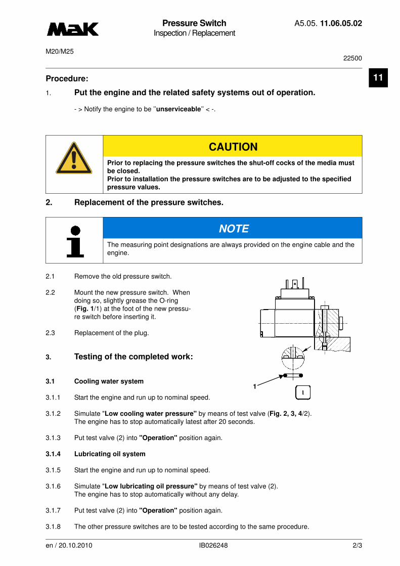
Pressure SwitchInspection / Replacement
A5.05. 11.06.05.02
22500M20/M25
11
Procedure:1. Put the engine and the related safety systems out of operation.
- > Notify the engine to be ’’unserviceable’’ < -.
2. Replacement of the pressure switches.
2.1 Remove the old pressure switch.
2.2 Mount the new pressure switch. When doing so, slightly grease the O-ring (Fig. 1/1) at the foot of the new pressu-re switch before inserting it.
2.3 Replacement of the plug.
3. Testing of the completed work:
3.1 Cooling water system
3.1.1 Start the engine and run up to nominal speed.
3.1.2 Simulate "Low cooling water pressure" by means of test valve (Fig. 2, 3, 4/2).The engine has to stop automatically latest after 20 seconds.
3.1.3 Put test valve (2) into "Operation" position again.
3.1.4 Lubricating oil system
3.1.5 Start the engine and run up to nominal speed.
3.1.6 Simulate "Low lubricating oil pressure" by means of test valve (2). The engine has to stop automatically without any delay.
3.1.7 Put test valve (2) into "Operation" position again.
3.1.8 The other pressure switches are to be tested according to the same procedure.
CAUTION
Prior to replacing the pressure switches the shut-off cocks of the media must
be closed.
Prior to installation the pressure switches are to be adjusted to the specified
pressure values.
NOTE
The measuring point designations are always provided on the engine cable and the engine.
1
en / 20.10.2010 IB026248 2/3

Pressure SwitchInspection / Replacement
A5.05. 11.06.05.02
22500M20/M25
11
3.1.9 Put the engine and the safety system into normal operating condition again.
-> Notify the engine to be "ready for operation" <-.
en / 20.10.2010 IB026248 3/3

Pressure SwitchMaintenance / Adjust
A5.05. 11.06.06.02
M20/M25/M32/M43
11
-------
See also: 11.06.05.nn
Spare parts list:
Time requirement: 1 Pers./ 0,25 h
Personnel qualification: skilled engine hand
-------------------------------------------------------------------------------------------------------------------------Operating medium: Heavy fuel and distillate fuel
Tools:
Pressure calibrating device W1*Electric continuity tester (multimeter) W2** no picture
Procedure:
1. Mount new pressure switch, see A5.05.11.06.05.nn.
2. Close shut-off valve (Fig. 3/6) of the corresponding medium to the pressure pipe.
2.1 Remove the plug from the pressure switch and connect the pressure calibrating device (W1) to the test connection. The adjustment value is to be inferred from the list of measuring points, see
"engine documentation, chapter "Control/Regulation".
2.2 In pressureless state the pressure switch contacts (Fig. 1)
1 + 2 are closed and contacts 1 + 3 are open (ohmic flow).
2.3 When the pressure drops, the pressure switch should switch at the measuring point value, in this state contacts 1 + 2 are open and contacts 1 + 3 are closed.
2.4 If a pressure switch is replaced, the switching value is to be inferred from the list of measuring points.(The measuring point number is indicated on the cable or the related nameplate.)
NOTE
If the pressure switch responds before or after the read limit, the switching point has to be readjusted, see item 3.
en / 26.11.2010 IB025583 1/2
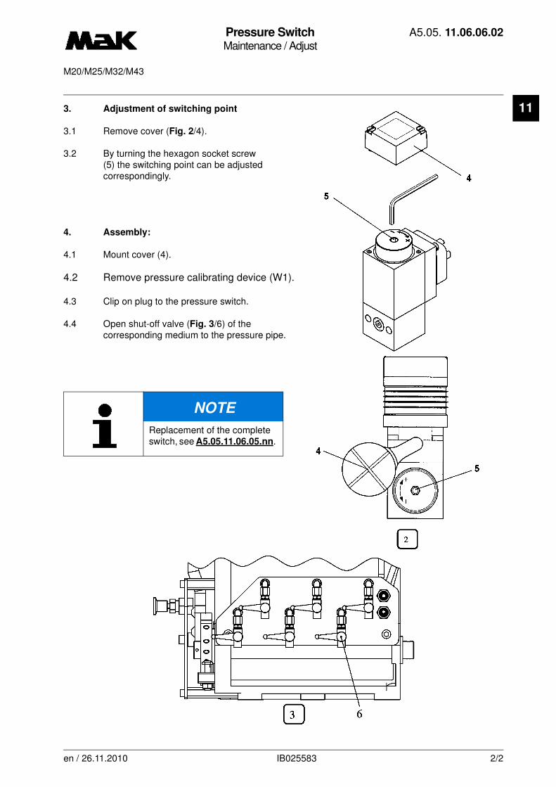
Pressure SwitchMaintenance / Adjust
A5.05. 11.06.06.02
M20/M25/M32/M43
11
3. Adjustment of switching point3.1 Remove cover (Fig. 2/4).
3.2 By turning the hexagon socket screw (5) the switching point can be adjusted correspondingly.
4. Assembly:
4.1 Mount cover (4).
4.2 Remove pressure calibrating device (W1).
4.3 Clip on plug to the pressure switch.
4.4 Open shut-off valve (Fig. 3/6) of thecorresponding medium to the pressure pipe.
NOTE
Replacement of the complete switch, see A5.05.11.06.05.nn.
en / 26.11.2010 IB025583 2/2
Crankcase Monitoring DeviceInspection / Checking
A5.05. 11.09.01.03
1500, 750, 7500M20/M25/M32/M43/M453C/M552C/M601C
en / 01.04.2010 IB021758 1/1
11See also:
Spare parts list: B1.05.11.nn4810
Time requirement: 2 Pers./ 1,00 h
Personnel qualification: skilled engine hand
--------------------------------------------------------------------------------------------------------------------------------Operating medium: Heavy fuel and distillate fuel
Maintenance:
a) Check the underpressure in the measuring chamber every 750 h
b) Clean the infrared filter and replace the sintered bronze filter in the measuring attachment every 1.500 h
c) Replace the sintered bronze filter in the pressure control every 7.500 h
Tools:
Test equipment and spare parts.Service box
NOTE
Maintenance and trouble shooting, refer, see "engine documentation, chapter "Ex-ternal Documentation".
CAUTION
The engine is not monitored in the event of the device malfunctioning. his can result in engine damage!
Vibration DamperMaintenance / Disassembly and reassembly
A5.05. 12.04.01.03
30000M20
12
-------
See also:
Spare parts list: B1.05.12.1.6347
Time requirement: 0 Pers./ 0,00 h
Personnel qualification: skilled engine hand
-------------------------------------------------------------------------------------------------------------------------
Operating medium: Heavy fuel and distillate fuel
Maintenance:
every 30,000 h
Auxiliary material:
Molykote paste “G-Rapid Plus” *Silicone sealing compound “Dirco-Grau” *
* or a product of equal standard
Sequence of operations:
1. Disassmbly
1.1 Remove pump carrier plate (3).
1.2 Mark two-piece stop disk (4), loosen screws (5), remove stop disk. If necessary, push off with screw M12 in thread (6) (observe marking).
1.3 Mark position of flywheel rim (7) to carrier (8).
1.4 Pull out spring assemblies (9) with a wire hook.
1.4.1 Inspect stop surfaces of the spring assemblies for wear.Smooth slight burr with soft emery paper. Replace spring assembly (9) in case of deeper grooves since there is a danger of the spring leaf ends snap getting caught in the grooves and breaking during further operation.
NOTE
When replacing (possible by way of exchange) and/or fitting dampers coat fastening screws (Fig. 1/1), threads and screw head rests with Molykote paste “G-Rapid Plus” and tighten with a pre-torque of
M = 100 Nm + 90°°°° angle of rotation.
The vibration damper is connected to the lube oil system of the engine.
Free passage of oil bores (2) must be ensured for the proper functioning of the dam-per!
If running of the engine becomes unbalanced at certain speeds, the cause can be a defective damper. In order to prevent further damage, avoid critical speed range and determine defect as soon as possible by torsional vibration measurement.
en / 30.09.2010 IB022217 1/2
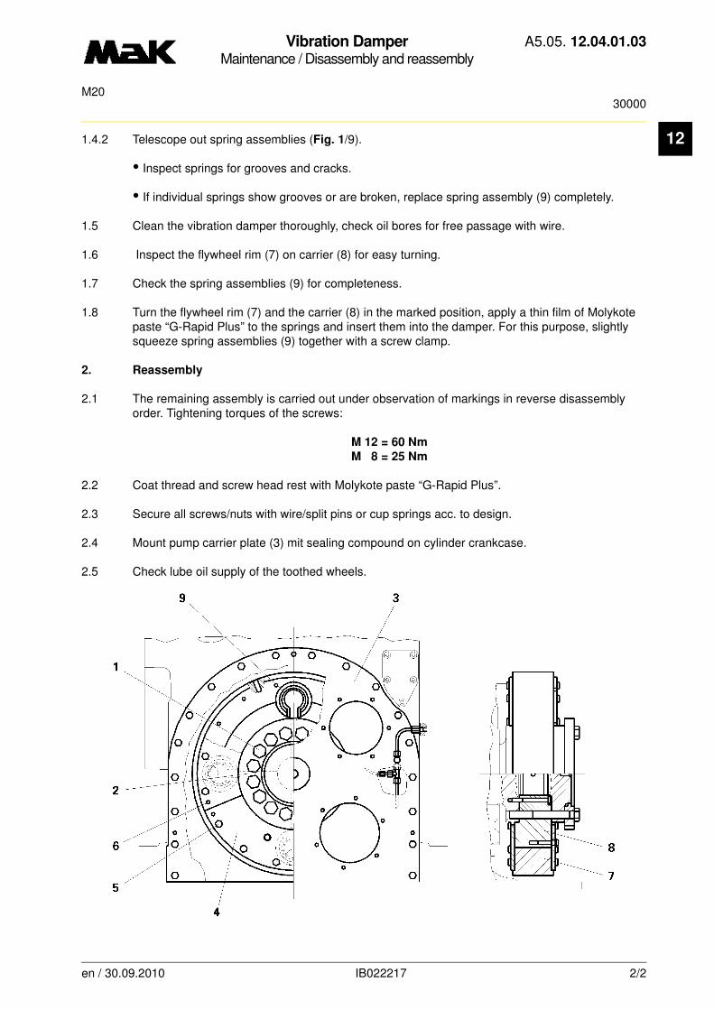
Vibration DamperMaintenance / Disassembly and reassembly
A5.05. 12.04.01.03
30000M20
12
1.4.2 Telescope out spring assemblies (Fig. 1/9).• Inspect springs for grooves and cracks.
• If individual springs show grooves or are broken, replace spring assembly (9) completely.
1.5 Clean the vibration damper thoroughly, check oil bores for free passage with wire.
1.6 Inspect the flywheel rim (7) on carrier (8) for easy turning.
1.7 Check the spring assemblies (9) for completeness.
1.8 Turn the flywheel rim (7) and the carrier (8) in the marked position, apply a thin film of Molykote paste “G-Rapid Plus” to the springs and insert them into the damper. For this purpose, slightly squeeze spring assemblies (9) together with a screw clamp.
2. Reassembly
2.1 The remaining assembly is carried out under observation of markings in reverse disassembly order. Tightening torques of the screws:
M 12 = 60 Nm
M 8 = 25 Nm
2.2 Coat thread and screw head rest with Molykote paste “G-Rapid Plus”.
2.3 Secure all screws/nuts with wire/split pins or cup springs acc. to design.
2.4 Mount pump carrier plate (3) mit sealing compound on cylinder crankcase.
2.5 Check lube oil supply of the toothed wheels.
en / 30.09.2010 IB022217 2/2