Embed Size (px)
Citation preview
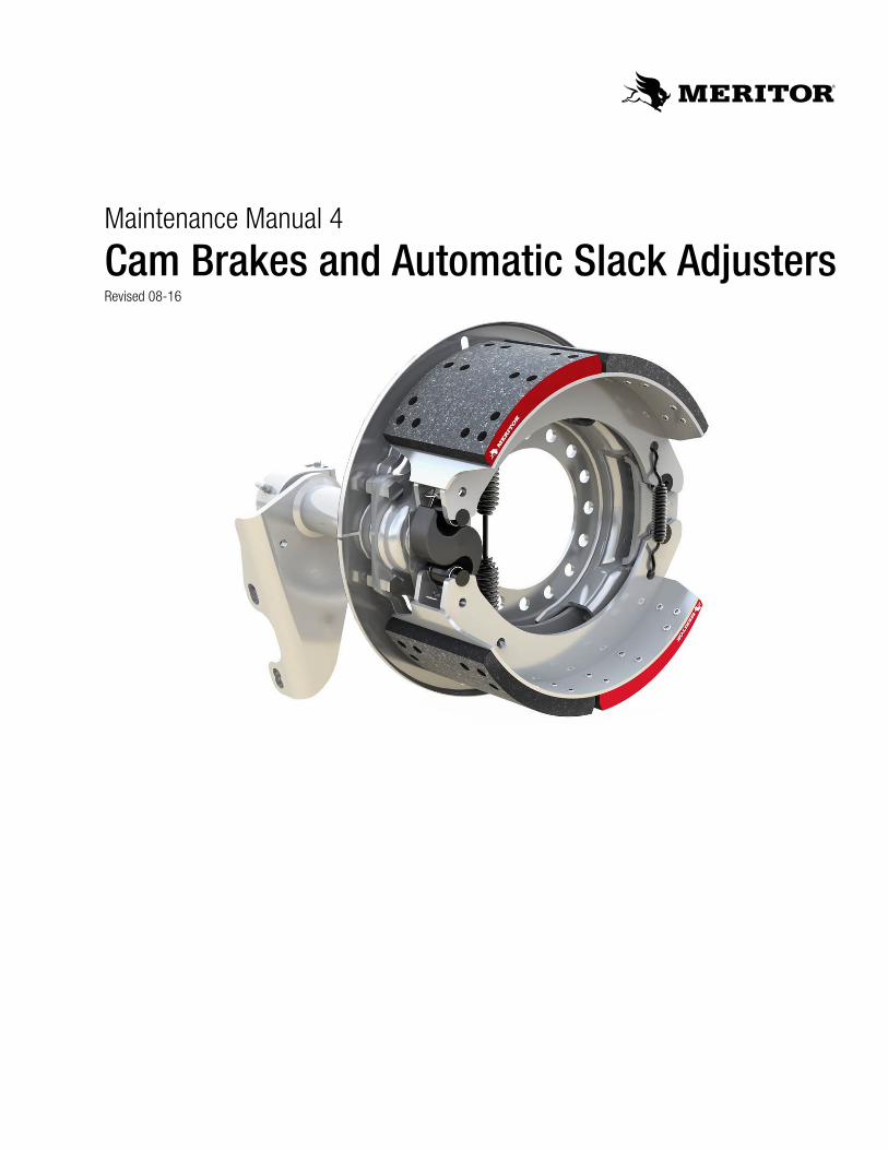
Maintenance Manual 4
Cam Brakes and Automatic Slack AdjustersRevised 08-16
Service Notes
Information contained in this publication was in effect at the time the publication was approved for printing and is subject to change without notice or liability. Meritor Heavy Vehicle Systems, LLC, reserves the right to revise the information presented or to discontinue the production of parts described at any time.
Meritor Maintenance Manual 4 (Revised 08-16)
About This ManualThis manual provides maintenance and service information for Meritor cam brakes and automatic slack adjuster.
Before You Begin1. Read and understand all instructions and procedures before
you begin to service components.
2. Read and observe all Warning and Caution hazard alert messages in this publication. They provide information that can help prevent serious personal injury, damage to components, or both.
3. Follow your company’s maintenance and service, installation, and diagnostics guidelines.
4. Use special tools when required to help avoid serious personal injury and damage to components.
Important InformationMeritor automatic slack adjusters (ASAs) should not need to be manually adjusted in service. ASAs should not have to be adjusted to correct excessive push rod stroke. The excessive stroke may be an indication that a problem exists with the foundation brake, ASA, brake actuator or other system components.
Meritor recommends troubleshooting the problem, replacing suspect components and then confirming proper brake operation prior to returning the vehicle into service.
In the event that a manual adjustment must be made (although not a common practice), a service appointment and full foundation brake, ASA, and other system component inspection should be conducted as soon as possible to ensure integrity of the overall brake system.
For Meritor brake adjustment, refer to the brake adjustment tables in this manual. For non-Meritor brake adjusters, refer to the brake manufacturer’s service procedures.
Hazard Alert Messages and Torque Symbols
WARNINGA Warning alerts you to an instruction or procedure that you must follow exactly to avoid serious personal injury and damage to components.
CAUTIONA Caution alerts you to an instruction or procedure that you must follow exactly to avoid damage to components.
@ This symbol alerts you to tighten fasteners to a specified torque value.
How to Obtain Additional Maintenance, Service and Product InformationVisit Literature on Demand at meritor.com to access and order additional information.
Contact the Meritor OnTrac™ Customer Call Center at 866-668-7221 (United States and Canada); 001-800-889-1834 (Mexico); or email [email protected].
If Tools, Supplies and Brake Service Kits are Specified in This ManualContact Meritor’s Commercial Vehicle Aftermarket at 888-725-9355.
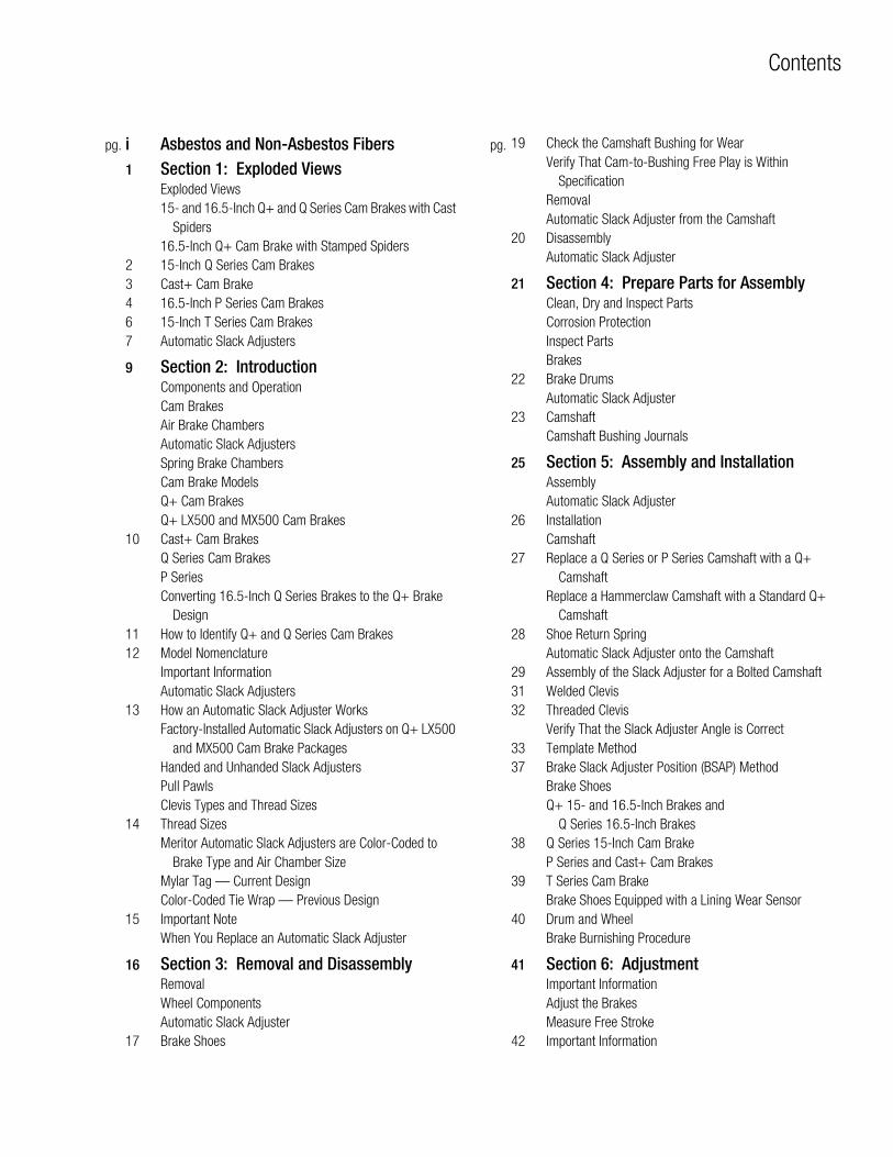
pg. pg.
Contents
i Asbestos and Non-Asbestos Fibers1 Section 1: Exploded Views
Exploded Views15- and 16.5-Inch Q+ and Q Series Cam Brakes with Cast
Spiders16.5-Inch Q+ Cam Brake with Stamped Spiders
2 15-Inch Q Series Cam Brakes3 Cast+ Cam Brake4 16.5-Inch P Series Cam Brakes6 15-Inch T Series Cam Brakes7 Automatic Slack Adjusters
9 Section 2: IntroductionComponents and OperationCam BrakesAir Brake ChambersAutomatic Slack AdjustersSpring Brake ChambersCam Brake ModelsQ+ Cam BrakesQ+ LX500 and MX500 Cam Brakes
10 Cast+ Cam BrakesQ Series Cam BrakesP SeriesConverting 16.5-Inch Q Series Brakes to the Q+ Brake
Design11 How to Identify Q+ and Q Series Cam Brakes12 Model Nomenclature
Important InformationAutomatic Slack Adjusters
13 How an Automatic Slack Adjuster WorksFactory-Installed Automatic Slack Adjusters on Q+ LX500
and MX500 Cam Brake PackagesHanded and Unhanded Slack AdjustersPull PawlsClevis Types and Thread Sizes
14 Thread SizesMeritor Automatic Slack Adjusters are Color-Coded to
Brake Type and Air Chamber SizeMylar Tag — Current DesignColor-Coded Tie Wrap — Previous Design
15 Important NoteWhen You Replace an Automatic Slack Adjuster
16 Section 3: Removal and DisassemblyRemovalWheel ComponentsAutomatic Slack Adjuster
17 Brake Shoes
19 Check the Camshaft Bushing for WearVerify That Cam-to-Bushing Free Play is Within
SpecificationRemovalAutomatic Slack Adjuster from the Camshaft
20 DisassemblyAutomatic Slack Adjuster
21 Section 4: Prepare Parts for AssemblyClean, Dry and Inspect PartsCorrosion ProtectionInspect PartsBrakes
22 Brake DrumsAutomatic Slack Adjuster
23 CamshaftCamshaft Bushing Journals
25 Section 5: Assembly and InstallationAssemblyAutomatic Slack Adjuster
26 InstallationCamshaft
27 Replace a Q Series or P Series Camshaft with a Q+ Camshaft
Replace a Hammerclaw Camshaft with a Standard Q+ Camshaft
28 Shoe Return SpringAutomatic Slack Adjuster onto the Camshaft
29 Assembly of the Slack Adjuster for a Bolted Camshaft31 Welded Clevis32 Threaded Clevis
Verify That the Slack Adjuster Angle is Correct33 Template Method37 Brake Slack Adjuster Position (BSAP) Method
Brake ShoesQ+ 15- and 16.5-Inch Brakes and
Q Series 16.5-Inch Brakes38 Q Series 15-Inch Cam Brake
P Series and Cast+ Cam Brakes39 T Series Cam Brake
Brake Shoes Equipped with a Lining Wear Sensor40 Drum and Wheel
Brake Burnishing Procedure
41 Section 6: AdjustmentImportant InformationAdjust the BrakesMeasure Free Stroke
42 Important Information
Contents
pg. pg.42 Commercial Vehicle Safety Alliance (CVSA) GuidelinesMeasure Push Rod Travel or Adjusted Chamber Stroke
43 Alternate Method to Measure Push Rod Travel or Adjusted Chamber Stroke
CVSA North American Out-of-Service Criteria Reference Tables
44 Standard- and Long-Stroke Clamp Type Brake Chamber Identification
Standard-Stroke ChambersLong-Stroke Chambers
45 Section 7: MaintenanceLubricationCam Brakes
47 Camshaft BushingsRollers and Anchor PinsImportant InformationAutomatic Slack Adjusters
48 Adjust the BrakesSlack Adjuster Inspection and LubricationSlack Adjusters Manufactured Before 1993
49 Grease SpecificationsAnti-Seize CompoundFactory-Installed Automatic Slack Adjusters on Q+ LX500
and MX500 Cam Brake Packages50 Inspection and Maintenance Intervals
Reline the BrakesImportant Information on Linings and Primary Shoe
LocationsUse the Correct Lining MaterialSingle AxlesTandem Axles
51 Combination Friction LiningsPrimary Shoe LocationsMajor OverhaulInspectionBefore You Return the Vehicle to Service
53 Section 8: DiagnosticsImportant Information
54 Troubleshooting
58 Section 9: SpecificationsTorque SpecificationsCam Brakes
Asbestos and Non-Asbestos Fibers
iMeritor Maintenance Manual 4 (Revised 08-16)
Figure 0.1
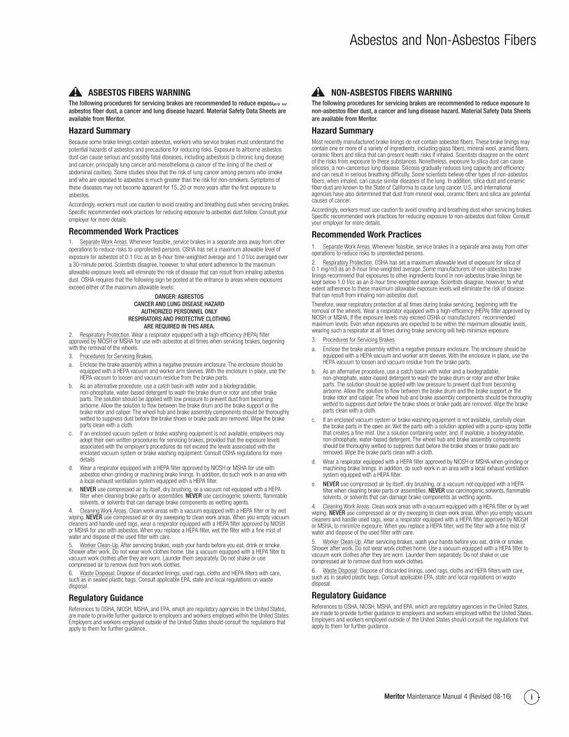
ASBESTOS FIBERS WARNING The following procedures for servicing brakes are recommended to reduce exposure to asbestos fiber dust, a cancer and lung disease hazard. Material Safety Data Sheets are available from Meritor.
Hazard SummaryBecause some brake linings contain asbestos, workers who service brakes must understand the potential hazards of asbestos and precautions for reducing risks. Exposure to airborne asbestos dust can cause serious and possibly fatal diseases, including asbestosis (a chronic lung disease) and cancer, principally lung cancer and mesothelioma (a cancer of the lining of the chest or abdominal cavities). Some studies show that the risk of lung cancer among persons who smoke and who are exposed to asbestos is much greater than the risk for non-smokers. Symptoms of these diseases may not become apparent for 15, 20 or more years after the first exposure to asbestos.
Accordingly, workers must use caution to avoid creating and breathing dust when servicing brakes. Specific recommended work practices for reducing exposure to asbestos dust follow. Consult your employer for more details.
Recommended Work Practices1. Separate Work Areas. Whenever feasible, service brakes in a separate area away from other operations to reduce risks to unprotected persons. OSHA has set a maximum allowable level of exposure for asbestos of 0.1 f/cc as an 8-hour time-weighted average and 1.0 f/cc averaged over a 30-minute period. Scientists disagree, however, to what extent adherence to the maximum allowable exposure levels will eliminate the risk of disease that can result from inhaling asbestos dust. OSHA requires that the following sign be posted at the entrance to areas where exposures exceed either of the maximum allowable levels:
DANGER: ASBESTOSCANCER AND LUNG DISEASE HAZARD
AUTHORIZED PERSONNEL ONLYRESPIRATORS AND PROTECTIVE CLOTHING
ARE REQUIRED IN THIS AREA. 2. Respiratory Protection. Wear a respirator equipped with a high-efficiency (HEPA) filter approved by NIOSH or MSHA for use with asbestos at all times when servicing brakes, beginning with the removal of the wheels.3. Procedures for Servicing Brakes.a. Enclose the brake assembly within a negative pressure enclosure. The enclosure should be
equipped with a HEPA vacuum and worker arm sleeves. With the enclosure in place, use the HEPA vacuum to loosen and vacuum residue from the brake parts.
b. As an alternative procedure, use a catch basin with water and a biodegradable, non-phosphate, water-based detergent to wash the brake drum or rotor and other brake parts. The solution should be applied with low pressure to prevent dust from becoming airborne. Allow the solution to flow between the brake drum and the brake support or the brake rotor and caliper. The wheel hub and brake assembly components should be thoroughly wetted to suppress dust before the brake shoes or brake pads are removed. Wipe the brake parts clean with a cloth.
c. If an enclosed vacuum system or brake washing equipment is not available, employers may adopt their own written procedures for servicing brakes, provided that the exposure levels associated with the employer’s procedures do not exceed the levels associated with the enclosed vacuum system or brake washing equipment. Consult OSHA regulations for more details.
d. Wear a respirator equipped with a HEPA filter approved by NIOSH or MSHA for use with asbestos when grinding or machining brake linings. In addition, do such work in an area with a local exhaust ventilation system equipped with a HEPA filter.
e. NEVER use compressed air by itself, dry brushing, or a vacuum not equipped with a HEPA filter when cleaning brake parts or assemblies. NEVER use carcinogenic solvents, flammable solvents, or solvents that can damage brake components as wetting agents.
4. Cleaning Work Areas. Clean work areas with a vacuum equipped with a HEPA filter or by wet wiping. NEVER use compressed air or dry sweeping to clean work areas. When you empty vacuum cleaners and handle used rags, wear a respirator equipped with a HEPA filter approved by NIOSH or MSHA for use with asbestos. When you replace a HEPA filter, wet the filter with a fine mist of water and dispose of the used filter with care.5. Worker Clean-Up. After servicing brakes, wash your hands before you eat, drink or smoke. Shower after work. Do not wear work clothes home. Use a vacuum equipped with a HEPA filter to vacuum work clothes after they are worn. Launder them separately. Do not shake or use compressed air to remove dust from work clothes.6. Waste Disposal. Dispose of discarded linings, used rags, cloths and HEPA filters with care, such as in sealed plastic bags. Consult applicable EPA, state and local regulations on waste disposal.
Regulatory GuidanceReferences to OSHA, NIOSH, MSHA, and EPA, which are regulatory agencies in the United States, are made to provide further guidance to employers and workers employed within the United States. Employers and workers employed outside of the United States should consult the regulations that apply to them for further guidance.
NON-ASBESTOS FIBERS WARNING The following procedures for servicing brakes are recommended to reduce exposure to non-asbestos fiber dust, a cancer and lung disease hazard. Material Safety Data Sheets are available from Meritor.
Hazard SummaryMost recently manufactured brake linings do not contain asbestos fibers. These brake linings may contain one or more of a variety of ingredients, including glass fibers, mineral wool, aramid fibers, ceramic fibers and silica that can present health risks if inhaled. Scientists disagree on the extent of the risks from exposure to these substances. Nonetheless, exposure to silica dust can cause silicosis, a non-cancerous lung disease. Silicosis gradually reduces lung capacity and efficiency and can result in serious breathing difficulty. Some scientists believe other types of non-asbestos fibers, when inhaled, can cause similar diseases of the lung. In addition, silica dust and ceramic fiber dust are known to the State of California to cause lung cancer. U.S. and international agencies have also determined that dust from mineral wool, ceramic fibers and silica are potential causes of cancer.
Accordingly, workers must use caution to avoid creating and breathing dust when servicing brakes. Specific recommended work practices for reducing exposure to non-asbestos dust follow. Consult your employer for more details.
Recommended Work Practices1. Separate Work Areas. Whenever feasible, service brakes in a separate area away from other operations to reduce risks to unprotected persons.
2. Respiratory Protection. OSHA has set a maximum allowable level of exposure for silica of 0.1 mg/m3 as an 8-hour time-weighted average. Some manufacturers of non-asbestos brake linings recommend that exposures to other ingredients found in non-asbestos brake linings be kept below 1.0 f/cc as an 8-hour time-weighted average. Scientists disagree, however, to what extent adherence to these maximum allowable exposure levels will eliminate the risk of disease that can result from inhaling non-asbestos dust.
Therefore, wear respiratory protection at all times during brake servicing, beginning with the removal of the wheels. Wear a respirator equipped with a high-efficiency (HEPA) filter approved by NIOSH or MSHA, if the exposure levels may exceed OSHA or manufacturers’ recommended maximum levels. Even when exposures are expected to be within the maximum allowable levels, wearing such a respirator at all times during brake servicing will help minimize exposure.
3. Procedures for Servicing Brakes.
a. Enclose the brake assembly within a negative pressure enclosure. The enclosure should be equipped with a HEPA vacuum and worker arm sleeves. With the enclosure in place, use the HEPA vacuum to loosen and vacuum residue from the brake parts.
b. As an alternative procedure, use a catch basin with water and a biodegradable, non-phosphate, water-based detergent to wash the brake drum or rotor and other brake parts. The solution should be applied with low pressure to prevent dust from becoming airborne. Allow the solution to flow between the brake drum and the brake support or the brake rotor and caliper. The wheel hub and brake assembly components should be thoroughly wetted to suppress dust before the brake shoes or brake pads are removed. Wipe the brake parts clean with a cloth.
c. If an enclosed vacuum system or brake washing equipment is not available, carefully clean the brake parts in the open air. Wet the parts with a solution applied with a pump-spray bottle that creates a fine mist. Use a solution containing water, and, if available, a biodegradable, non-phosphate, water-based detergent. The wheel hub and brake assembly components should be thoroughly wetted to suppress dust before the brake shoes or brake pads are removed. Wipe the brake parts clean with a cloth.
d. Wear a respirator equipped with a HEPA filter approved by NIOSH or MSHA when grinding or machining brake linings. In addition, do such work in an area with a local exhaust ventilation system equipped with a HEPA filter.
e. NEVER use compressed air by itself, dry brushing, or a vacuum not equipped with a HEPA filter when cleaning brake parts or assemblies. NEVER use carcinogenic solvents, flammable solvents, or solvents that can damage brake components as wetting agents.
4. Cleaning Work Areas. Clean work areas with a vacuum equipped with a HEPA filter or by wet wiping. NEVER use compressed air or dry sweeping to clean work areas. When you empty vacuum cleaners and handle used rags, wear a respirator equipped with a HEPA filter approved by NIOSH or MSHA, to minimize exposure. When you replace a HEPA filter, wet the filter with a fine mist of water and dispose of the used filter with care.
5. Worker Clean-Up. After servicing brakes, wash your hands before you eat, drink or smoke. Shower after work. Do not wear work clothes home. Use a vacuum equipped with a HEPA filter to vacuum work clothes after they are worn. Launder them separately. Do not shake or use compressed air to remove dust from work clothes.
6. Waste Disposal. Dispose of discarded linings, used rags, cloths and HEPA filters with care, such as in sealed plastic bags. Consult applicable EPA, state and local regulations on waste disposal.
Regulatory GuidanceReferences to OSHA, NIOSH, MSHA, and EPA, which are regulatory agencies in the United States, are made to provide further guidance to employers and workers employed within the United States. Employers and workers employed outside of the United States should consult the regulations that apply to them for further guidance.
1 Exploded Views
0 Meritor Maintenance Manual 4 (Revised 08-16)
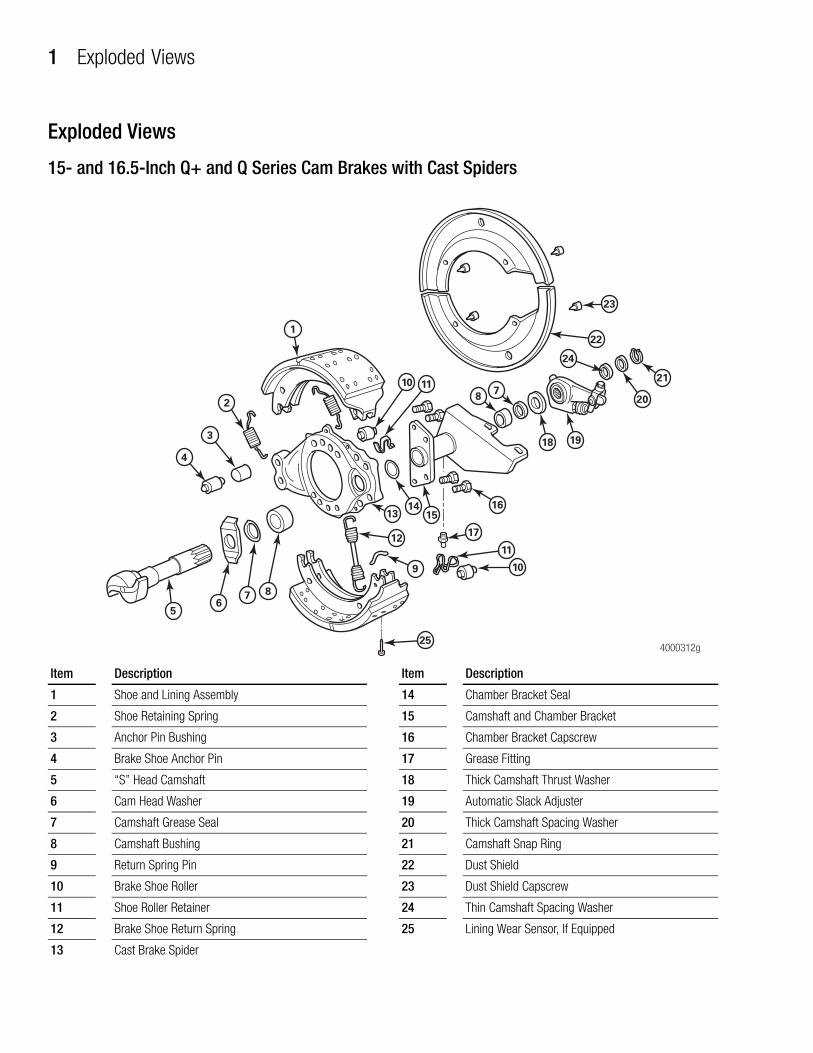
1 Exploded ViewsExploded Views
15- and 16.5-Inch Q+ and Q Series Cam Brakes with Cast Spiders
Figure 1.1
4000312g25
1
8
18 19
20
21
22
23
710 11
1413
12
9
11
10
16
17
15
876
5
2
24
3
4
Item Description
1 Shoe and Lining Assembly
2 Shoe Retaining Spring
3 Anchor Pin Bushing
4 Brake Shoe Anchor Pin
5 “S” Head Camshaft
6 Cam Head Washer
7 Camshaft Grease Seal
8 Camshaft Bushing
9 Return Spring Pin
10 Brake Shoe Roller
11 Shoe Roller Retainer
12 Brake Shoe Return Spring
13 Cast Brake Spider
14 Chamber Bracket Seal
15 Camshaft and Chamber Bracket
16 Chamber Bracket Capscrew
17 Grease Fitting
18 Thick Camshaft Thrust Washer
19 Automatic Slack Adjuster
20 Thick Camshaft Spacing Washer
21 Camshaft Snap Ring
22 Dust Shield
23 Dust Shield Capscrew
24 Thin Camshaft Spacing Washer
25 Lining Wear Sensor, If Equipped
Item Description
1 Exploded Views
1Meritor Maintenance Manual 4 (Revised 08-16)
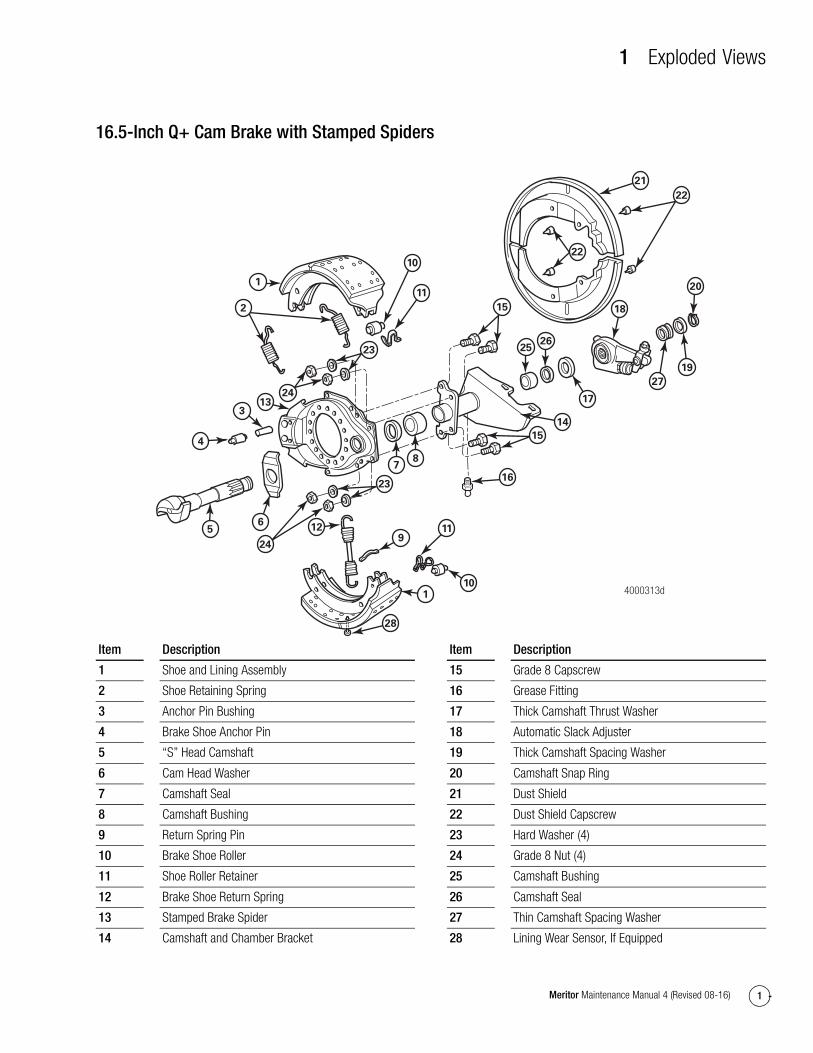
16.5-Inch Q+ Cam Brake with Stamped Spiders
Figure 1.2
28
4000313d
21
22
22
20
19
27
18
17
2625
15
14
15
16
23
10
11
24
1
2
4
313
78
9
23
11
101
56
24
12
Item Description
1 Shoe and Lining Assembly
2 Shoe Retaining Spring
3 Anchor Pin Bushing
4 Brake Shoe Anchor Pin
5 “S” Head Camshaft
6 Cam Head Washer
7 Camshaft Seal
8 Camshaft Bushing
9 Return Spring Pin
10 Brake Shoe Roller
11 Shoe Roller Retainer
12 Brake Shoe Return Spring
13 Stamped Brake Spider
14 Camshaft and Chamber Bracket
15 Grade 8 Capscrew
16 Grease Fitting
17 Thick Camshaft Thrust Washer
18 Automatic Slack Adjuster
19 Thick Camshaft Spacing Washer
20 Camshaft Snap Ring
21 Dust Shield
22 Dust Shield Capscrew
23 Hard Washer (4)
24 Grade 8 Nut (4)
25 Camshaft Bushing
26 Camshaft Seal
27 Thin Camshaft Spacing Washer
28 Lining Wear Sensor, If Equipped
Item Description
1 Exploded Views
2 Meritor Maintenance Manual 4 (Revised 08-16)
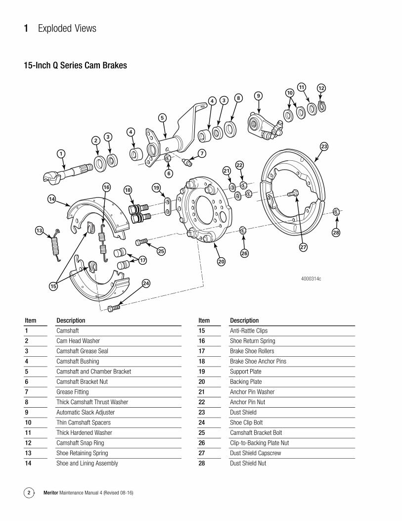
15-Inch Q Series Cam BrakesFigure 1.3
1
23
4
5
6
7
16
14
13
25
18 19
17
24
20
26
27
28
23
121110
9834
2221
15
4000314c
Item Description
1 Camshaft
2 Cam Head Washer
3 Camshaft Grease Seal
4 Camshaft Bushing
5 Camshaft and Chamber Bracket
6 Camshaft Bracket Nut
7 Grease Fitting
8 Thick Camshaft Thrust Washer
9 Automatic Slack Adjuster
10 Thin Camshaft Spacers
11 Thick Hardened Washer
12 Camshaft Snap Ring
13 Shoe Retaining Spring
14 Shoe and Lining Assembly
15 Anti-Rattle Clips
16 Shoe Return Spring
17 Brake Shoe Rollers
18 Brake Shoe Anchor Pins
19 Support Plate
20 Backing Plate
21 Anchor Pin Washer
22 Anchor Pin Nut
23 Dust Shield
24 Shoe Clip Bolt
25 Camshaft Bracket Bolt
26 Clip-to-Backing Plate Nut
27 Dust Shield Capscrew
28 Dust Shield Nut
Item Description
1 Exploded Views
3Meritor Maintenance Manual 4 (Revised 08-16)
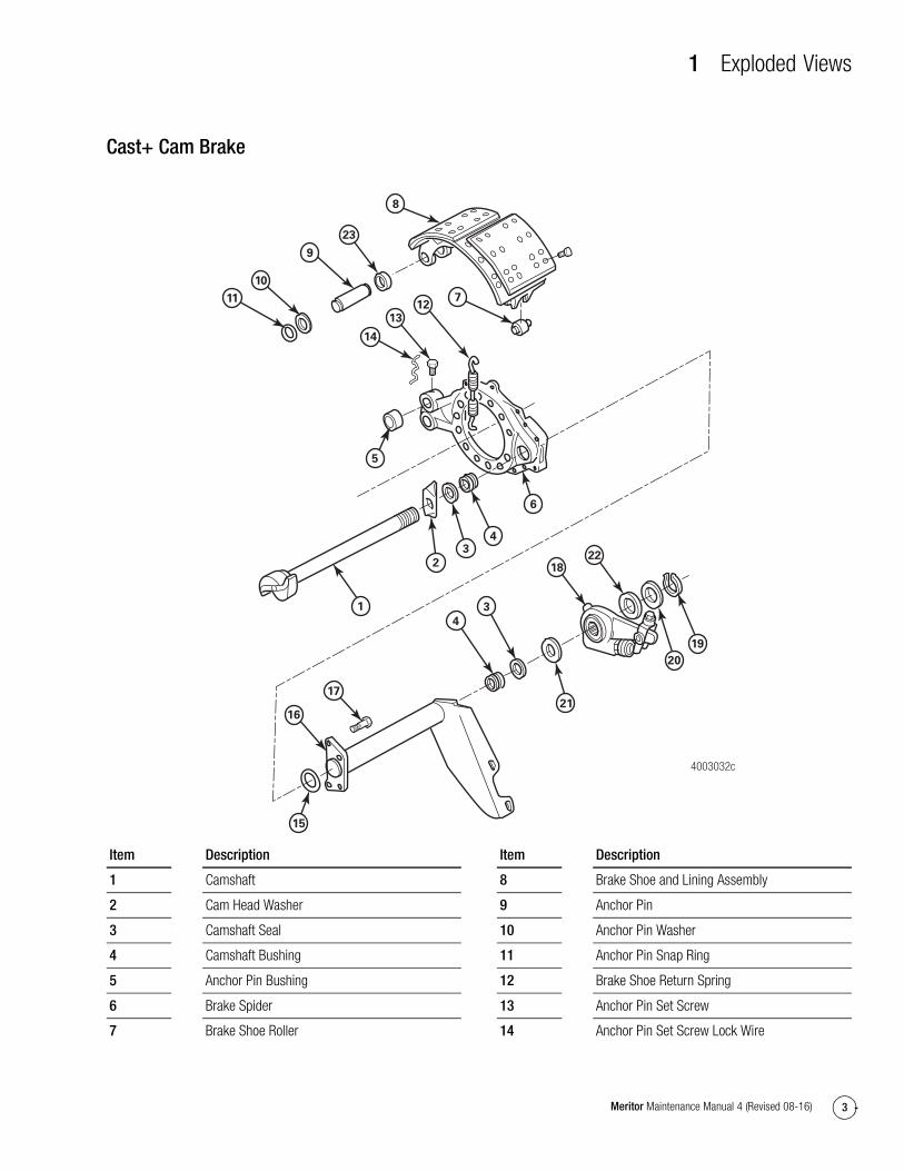
Cast+ Cam BrakeFigure 1.4
4003032c
8
9
10
11 712
13
14
5
6
43
2
1
4
17
16
15
3
1822
23
20
19
21
Item Description
1 Camshaft
2 Cam Head Washer
3 Camshaft Seal
4 Camshaft Bushing
5 Anchor Pin Bushing
6 Brake Spider
7 Brake Shoe Roller
8 Brake Shoe and Lining Assembly
9 Anchor Pin
10 Anchor Pin Washer
11 Anchor Pin Snap Ring
12 Brake Shoe Return Spring
13 Anchor Pin Set Screw
14 Anchor Pin Set Screw Lock Wire
Item Description
1 Exploded Views
4 Meritor Maintenance Manual 4 (Revised 08-16)
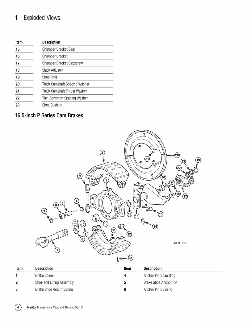
16.5-Inch P Series Cam Brakes
15 Chamber Bracket Seal
16 Chamber Bracket
17 Chamber Bracket Capscrew
18 Slack Adjuster
19 Snap Ring
20 Thick Camshaft Spacing Washer
21 Thick Camshaft Thrust Washer
22 Thin Camshaft Spacing Washer
23 Shoe Bushing
Item Description
Figure 1.5
24
220
21
189
10
1923
22
17
3
1
4
10
11
12
1413 15
16
56
4
7
8
9
4000315e
Item Description
1 Brake Spider
2 Shoe and Lining Assembly
3 Brake Shoe Return Spring
4 Anchor Pin Snap Ring
5 Brake Shoe Anchor Pin
6 Anchor Pin Bushing
Item Description
1 Exploded Views
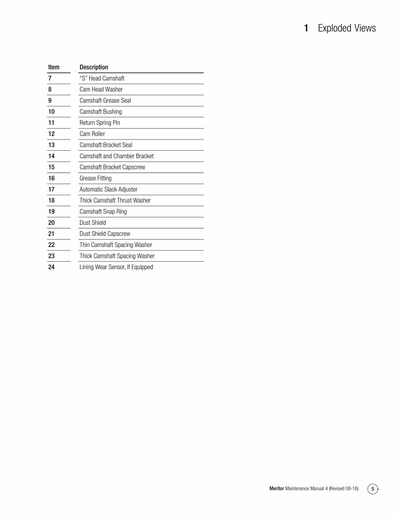
5Meritor Maintenance Manual 4 (Revised 08-16)
7 “S” Head Camshaft
8 Cam Head Washer
9 Camshaft Grease Seal
10 Camshaft Bushing
11 Return Spring Pin
12 Cam Roller
13 Camshaft Bracket Seal
14 Camshaft and Chamber Bracket
15 Camshaft Bracket Capscrew
16 Grease Fitting
17 Automatic Slack Adjuster
18 Thick Camshaft Thrust Washer
19 Camshaft Snap Ring
20 Dust Shield
21 Dust Shield Capscrew
22 Thin Camshaft Spacing Washer
23 Thick Camshaft Spacing Washer
24 Lining Wear Sensor, If Equipped
Item Description
1 Exploded Views
6 Meritor Maintenance Manual 4 (Revised 08-16)
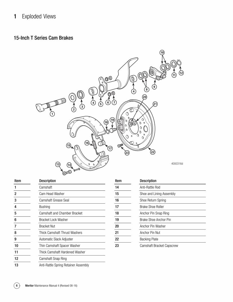
15-Inch T Series Cam BrakesFigure 1.6
4000316d
22
20
2176
54
32
1
1819
16
17
23
15
1413
9
4
1112
10
8
Item Description
1 Camshaft
2 Cam Head Washer
3 Camshaft Grease Seal
4 Bushing
5 Camshaft and Chamber Bracket
6 Bracket Lock Washer
7 Bracket Nut
8 Thick Camshaft Thrust Washers
9 Automatic Slack Adjuster
10 Thin Camshaft Spacer Washer
11 Thick Camshaft Hardened Washer
12 Camshaft Snap Ring
13 Anti-Rattle Spring Retainer Assembly
14 Anti-Rattle Rod
15 Shoe and Lining Assembly
16 Shoe Return Spring
17 Brake Shoe Roller
18 Anchor Pin Snap Ring
19 Brake Shoe Anchor Pin
20 Anchor Pin Washer
21 Anchor Pin Nut
22 Backing Plate
23 Camshaft Bracket Capscrew
Item Description
1 Exploded Views
7Meritor Maintenance Manual 4 (Revised 08-16)
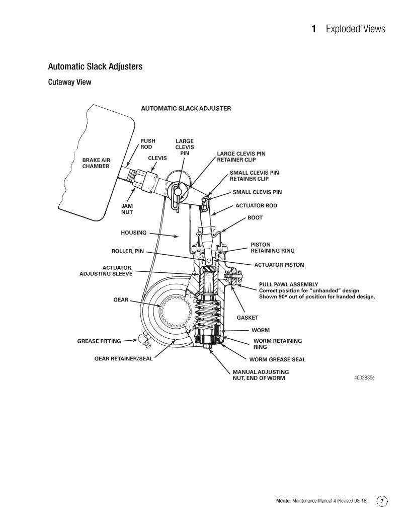
Automatic Slack Adjusters
Cutaway View
Figure 1.7
BRAKE AIRCHAMBER
PUSHROD
CLEVIS
LARGECLEVIS
PIN LARGE CLEVIS PIN RETAINER CLIP
SMALL CLEVIS PIN RETAINER CLIP
SMALL CLEVIS PIN
ACTUATOR ROD
BOOT
PISTONRETAINING RING
ACTUATOR PISTON
PULL PAWL ASSEMBLYCorrect position for “unhanded” design. Shown 90° out of position for handed design.
GASKET
WORM
WORM RETAININGRING
WORM GREASE SEAL
MANUAL ADJUSTINGNUT, END OF WORM
JAMNUT
HOUSING
ROLLER, PIN
ACTUATOR,ADJUSTING SLEEVE
GEAR
GREASE FITTING
GEAR RETAINER/SEAL
4002835e
AUTOMATIC SLACK ADJUSTER
1 Exploded Views
8 Meritor Maintenance Manual 4 (Revised 08-16)
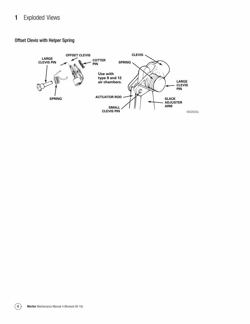
Offset Clevis with Helper Spring
Figure 1.8
LARGECLEVIS PIN
SPRING
OFFSET CLEVIS
COTTERPIN
SPRING
CLEVIS
LARGECLEVISPIN
SLACK ADJUSTER ARMSMALL
CLEVIS PIN
ACTUATOR ROD
Use withtype 9 and 12air chambers.
4002835c
2 Introduction
9Meritor Maintenance Manual 4 (Revised 08-16)
2 IntroductionComponents and Operation
Cam BrakesCam brakes are air-operated brakes — and the type of brake that is most commonly used in the commercial vehicle market. A cam brake consists of an air brake chamber and bracket, automatic slack adjuster, S-camshaft, brake hardware, shoes and linings, spider and brake drum.
At brake actuation, the S-cam rotates and pushes rollers located on the brake shoes against the brake drum. When a brake shoe is forced into the drum, friction slows the movement of the drum to stop the vehicle.
Air Brake ChambersThe vehicle supplies air to the brake system. When you push the brake pedal, a valve activates that uses compressed air to apply the brakes through the air brake chamber at each wheel end. Air brake chambers are specified by size for a particular brake and axle load. For example, a lightly-loaded steering axle might use a small chamber, while a heavily-loaded drive axle would use a larger chamber.
An air chamber also has a limited stroke movement, which is why maintaining cam brake adjustment is critical. The commercial vehicle industry uses two types of air brake chambers: the standard-stroke chamber and the long-stroke chamber.
Automatic Slack AdjustersTo adjust the brake as it wears, and help ensure the air brake chamber can produce enough actuation force, an automatic slack adjuster adjusts the amount of slack, or free play, in the brake. This adjustment is critical in air brakes, because with too little slack, the brake may drag and overheat. If there is too much slack, the brake may not generate enough braking effort to safely stop the vehicle.
Spring Brake ChambersAn air brake system requires parking brakes and emergency braking if the air system malfunctions; for example, if an air line ruptures. When the spring brake activates, air pressure is released from the spring brake chamber, which uses mechanical spring pressure as a braking force. The spring brake can be actuated automatically by low pressure, or it can be controlled mechanically to use as a parking brake.
Cam Brake Models
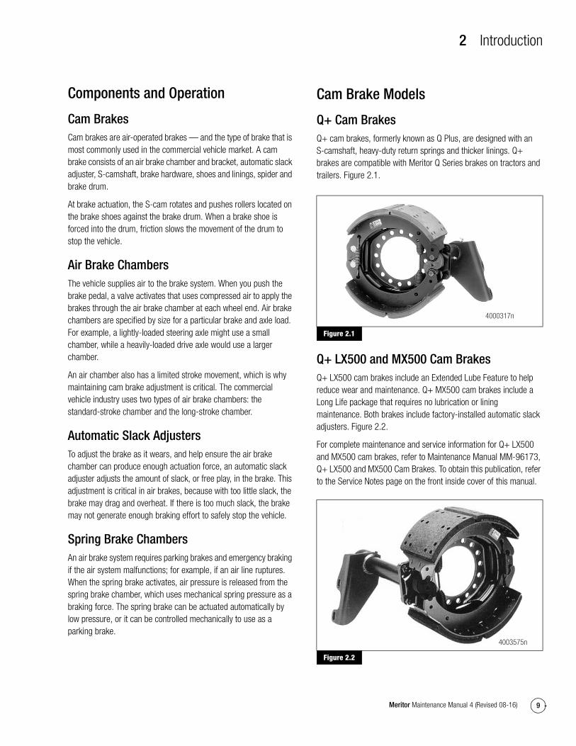
Q+ Cam BrakesQ+ cam brakes, formerly known as Q Plus, are designed with an S-camshaft, heavy-duty return springs and thicker linings. Q+ brakes are compatible with Meritor Q Series brakes on tractors and trailers. Figure 2.1.
Figure 2.1
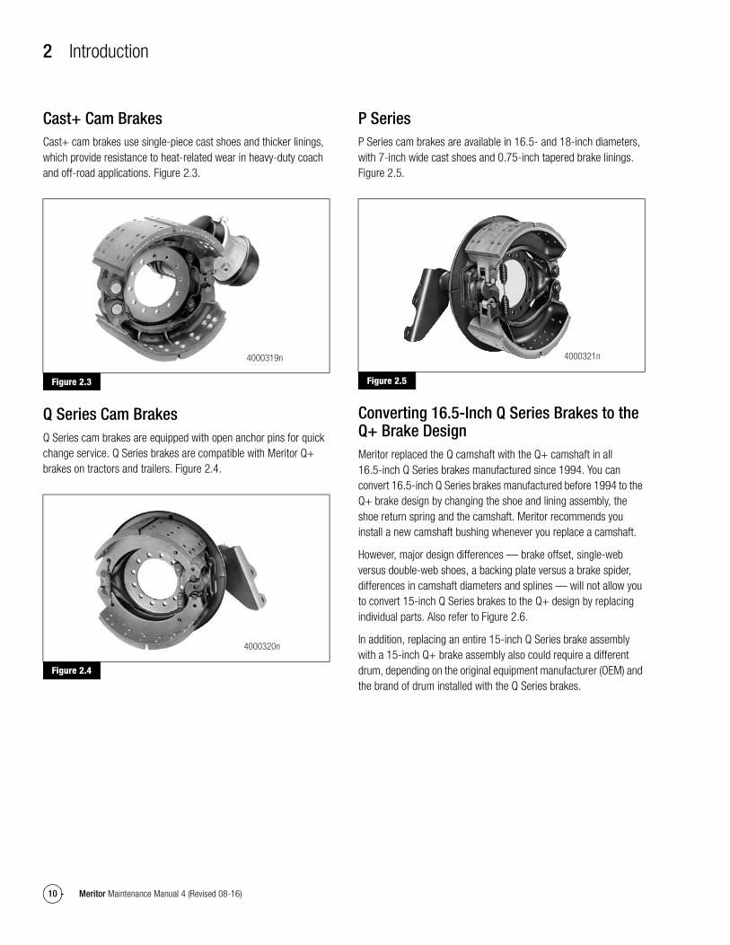
Q+ LX500 and MX500 Cam BrakesQ+ LX500 cam brakes include an Extended Lube Feature to help reduce wear and maintenance. Q+ MX500 cam brakes include a Long Life package that requires no lubrication or lining maintenance. Both brakes include factory-installed automatic slack adjusters. Figure 2.2.
For complete maintenance and service information for Q+ LX500 and MX500 cam brakes, refer to Maintenance Manual MM-96173, Q+ LX500 and MX500 Cam Brakes. To obtain this publication, refer to the Service Notes page on the front inside cover of this manual.
Figure 2.2
Figure 2.1
Figure 2.2
4000317n
4003575n
2 Introduction
10 Meritor Maintenance Manual 4 (Revised 08-16)
Cast+ Cam BrakesCast+ cam brakes use single-piece cast shoes and thicker linings, which provide resistance to heat-related wear in heavy-duty coach and off-road applications. Figure 2.3.
Figure 2.3
Q Series Cam BrakesQ Series cam brakes are equipped with open anchor pins for quick change service. Q Series brakes are compatible with Meritor Q+ brakes on tractors and trailers. Figure 2.4.
Figure 2.4
P SeriesP Series cam brakes are available in 16.5- and 18-inch diameters, with 7-inch wide cast shoes and 0.75-inch tapered brake linings. Figure 2.5.
Figure 2.5
Converting 16.5-Inch Q Series Brakes to the Q+ Brake DesignMeritor replaced the Q camshaft with the Q+ camshaft in all 16.5-inch Q Series brakes manufactured since 1994. You can convert 16.5-inch Q Series brakes manufactured before 1994 to the Q+ brake design by changing the shoe and lining assembly, the shoe return spring and the camshaft. Meritor recommends you install a new camshaft bushing whenever you replace a camshaft.
However, major design differences — brake offset, single-web versus double-web shoes, a backing plate versus a brake spider, differences in camshaft diameters and splines — will not allow you to convert 15-inch Q Series brakes to the Q+ design by replacing individual parts. Also refer to Figure 2.6.
In addition, replacing an entire 15-inch Q Series brake assembly with a 15-inch Q+ brake assembly also could require a different drum, depending on the original equipment manufacturer (OEM) and the brand of drum installed with the Q Series brakes.
Figure 2.3
Figure 2.4
4000319n
4000320n
Figure 2.5
4000321n

2 Introduction
11Meritor Maintenance Manual 4 (Revised 08-16)
How to Identify Q+ and Q Series Cam Brakes
Differences Between the Brakes
Figure 2.6
Figure 2.6
CAMTIP TO TIP = 3.25"
15" Q CAMSHAFT (1.25" DIA.-10 OR 24 SPLINES)
1.164 DIA.
4005132a
Q+ BRAKES Q SERIES BRAKES
FMSI NO. 4707
PLUS-SHAPED HOLES (+)STAMPED IN TABLE
MERITOR16.5 Q+
16.5 Q+STAMPED ON WEB
SHOE TAG
16.5" X 7" Q+ SHOE
28 RIVET HOLESIN TABLE
NO BULGEON WEB
DEEPER POCKET
INCREASEDLIFT
16.5Q+
LOCATED HERE
16.5" Q+ CAMSHAFT (1.5" DIA.-28 SPLINES)
1.18 DIA.
CAMTIP TO TIP = 4.25"
16 RIVETHOLES IN
TABLE
15" X 4" Q+ SHOE
DOUBLE WEB
15 Q+STAMPEDON WEB
FMSI NO. 4702
USED WITH SPIDERMERITOR
15 Q+
Q+
Q+
CAMTIP TO TIP = 3.38"
PART NUMBERLOCATED HERE
DEEPERPOCKET
INCREASEDLIFT
15Q+
LOCATED HERE
15" Q+ CAMSHAFT (1.5" DIA.-28 SPLINES)
0.988 DIA.
FMSI NO. 4515G
BULGEON WEB
16.5" X 7" Q SHOE
16.5 Q SERIESSTAMPED ON WEB
MERITOR16.5 Q SERIES
CAMTIP TO TIP = 4.22"
1.378 DIA.
16.5" Q CAMSHAFT (1.5" DIA.-10 OR 28 SPLINES)
14 RIVETHOLES
IN TABLE
FMSI NO. 1308 USED WITHBACKING PLATE
BULGE ON WEB
SINGLE WEB
15 Q SERIES STAMPED ON WEB
15" X 4" Q SHOE
MERITOR15 Q SERIES
NO BULGEON WEB
SHOE TAG
32 RIVET HOLESIN TABLE
PART NUMBERLOCATED HERE
2 Introduction
12 Meritor Maintenance Manual 4 (Revised 08-16)
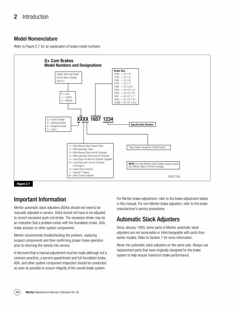
Model NomenclatureRefer to Figure 2.7 for an explanation of brake model numbers.
Figure 2.7
Important InformationMeritor automatic slack adjusters (ASAs) should not need to be manually adjusted in service. ASAs should not have to be adjusted to correct excessive push rod stroke. The excessive stroke may be an indication that a problem exists with the foundation brake, ASA, brake actuator or other system components.
Meritor recommends troubleshooting the problem, replacing suspect components and then confirming proper brake operation prior to returning the vehicle into service.
In the event that a manual adjustment must be made (although not a common practice), a service appointment and full foundation brake, ASA, and other system component inspection should be conducted as soon as possible to ensure integrity of the overall brake system.
For Meritor brake adjustment, refer to the brake adjustment tables in this manual. For non-Meritor brake adjusters, refer to the brake manufacturer’s service procedures.
Automatic Slack AdjustersSince January 1993, some parts of Meritor automatic slack adjusters are not serviceable or interchangeable with parts from earlier models. Refer to Section 1 for more information.
Never mix automatic slack adjusters on the same axle. Always use replacement parts that were originally designed for the brake system to help ensure maximum brake performance.
Figure 2.7
XXXX 1657 1234
Place holder needed for 16508 brakes
NOTE: For other Meritor brake models, please consult your Meritor sales or service manager.
Letters other than these are for older Q design (not Q+)
P = PlusL = LX500V = MX500
Specification Number
1 = With Manual Slack (Export Only)2 = With Automatic Slack3 = With Manual Slack and Air Chamber4 = With Automatic Slack and Air Chamber5 = Less Slack but with Air Chamber Supplied6 = Less Slack and Less Air Chamber
A through ZH = Heavy-Duty FeaturesT = TracLok™ Feature
Q = Quick ChangeS = Stamped SpiderK = Integral KnuckleC = Cast+
4002715b
Q+ Cam BrakesModel Numbers and Designations
W = Wear Sensor Installed
1540 = 15" x 4"1550 = 15" x 5"1560 = 15" x 6"1570 = 15" x 7"1586 = 15" x 8.6"1655 = 16-1/2" x 5"1656 = 16-1/2" x 6"1657 = 16-1/2" x 7"1658 = 16-1/2" x 8"16586 = 16-1/2" x 8.6"
Brake Size
2 Introduction
13Meritor Maintenance Manual 4 (Revised 08-16)
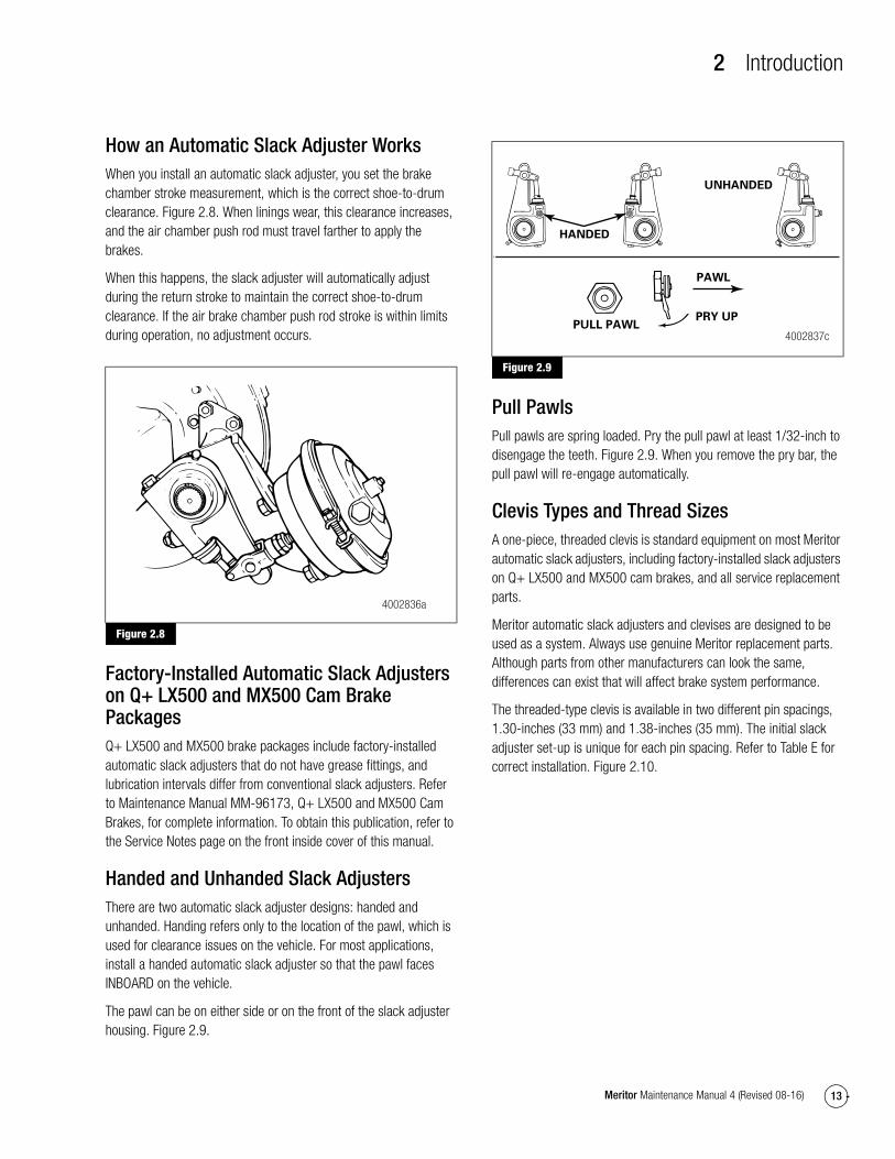
How an Automatic Slack Adjuster WorksWhen you install an automatic slack adjuster, you set the brake chamber stroke measurement, which is the correct shoe-to-drum clearance. Figure 2.8. When linings wear, this clearance increases, and the air chamber push rod must travel farther to apply the brakes.
When this happens, the slack adjuster will automatically adjust during the return stroke to maintain the correct shoe-to-drum clearance. If the air brake chamber push rod stroke is within limits during operation, no adjustment occurs.
Figure 2.8
Factory-Installed Automatic Slack Adjusters on Q+ LX500 and MX500 Cam Brake PackagesQ+ LX500 and MX500 brake packages include factory-installed automatic slack adjusters that do not have grease fittings, and lubrication intervals differ from conventional slack adjusters. Refer to Maintenance Manual MM-96173, Q+ LX500 and MX500 Cam Brakes, for complete information. To obtain this publication, refer to the Service Notes page on the front inside cover of this manual.
Handed and Unhanded Slack AdjustersThere are two automatic slack adjuster designs: handed and unhanded. Handing refers only to the location of the pawl, which is used for clearance issues on the vehicle. For most applications, install a handed automatic slack adjuster so that the pawl faces INBOARD on the vehicle.
The pawl can be on either side or on the front of the slack adjuster housing. Figure 2.9.
Figure 2.9
Pull PawlsPull pawls are spring loaded. Pry the pull pawl at least 1/32-inch to disengage the teeth. Figure 2.9. When you remove the pry bar, the pull pawl will re-engage automatically.
Clevis Types and Thread SizesA one-piece, threaded clevis is standard equipment on most Meritor automatic slack adjusters, including factory-installed slack adjusters on Q+ LX500 and MX500 cam brakes, and all service replacement parts.
Meritor automatic slack adjusters and clevises are designed to be used as a system. Always use genuine Meritor replacement parts. Although parts from other manufacturers can look the same, differences can exist that will affect brake system performance.
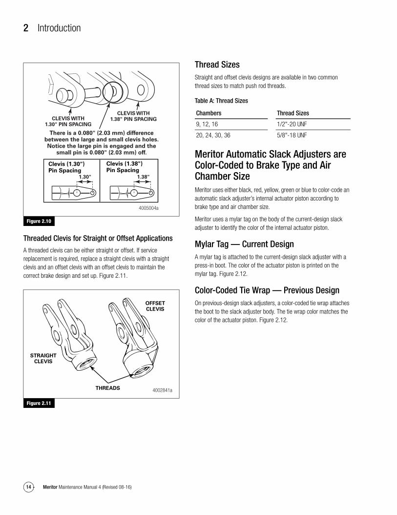
The threaded-type clevis is available in two different pin spacings, 1.30-inches (33 mm) and 1.38-inches (35 mm). The initial slack adjuster set-up is unique for each pin spacing. Refer to Table E for correct installation. Figure 2.10.
Figure 2.8
4002836a
Figure 2.9
HANDED
UNHANDED
PULL PAWLPRY UP
PAWL
4002837c
2 Introduction
14 Meritor Maintenance Manual 4 (Revised 08-16)
Figure 2.10
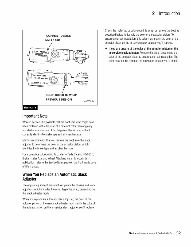
Threaded Clevis for Straight or Offset Applications
A threaded clevis can be either straight or offset. If service replacement is required, replace a straight clevis with a straight clevis and an offset clevis with an offset clevis to maintain the correct brake design and set up. Figure 2.11.
Figure 2.11
Thread SizesStraight and offset clevis designs are available in two common thread sizes to match push rod threads.
Table A: Thread Sizes
Meritor Automatic Slack Adjusters are Color-Coded to Brake Type and Air Chamber SizeMeritor uses either black, red, yellow, green or blue to color-code an automatic slack adjuster’s internal actuator piston according to brake type and air chamber size.
Meritor uses a mylar tag on the body of the current-design slack adjuster to identify the color of the internal actuator piston.
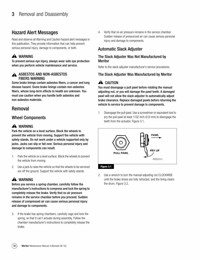
Mylar Tag — Current DesignA mylar tag is attached to the current-design slack adjuster with a press-in boot. The color of the actuator piston is printed on the mylar tag. Figure 2.12.
Color-Coded Tie Wrap — Previous DesignOn previous-design slack adjusters, a color-coded tie wrap attaches the boot to the slack adjuster body. The tie wrap color matches the color of the actuator piston. Figure 2.12.
Figure 2.10
Figure 2.11
4005004a
CLEVIS WITH1.38" PIN SPACINGCLEVIS WITH
1.30" PIN SPACING
There is a 0.080" (2.03 mm) differencebetween the large and small clevis holes.Notice the large pin is engaged and the
small pin is 0.080" (2.03 mm) off.
Clevis (1.38")Pin Spacing
Clevis (1.30")Pin Spacing
1.38"1.30"
STRAIGHTCLEVIS
THREADS
OFFSETCLEVIS
4002841a
Chambers Thread Sizes
9, 12, 16 1/2"-20 UNF
20, 24, 30, 36 5/8"-18 UNF
2 Introduction
15Meritor Maintenance Manual 4 (Revised 08-16)
Figure 2.12
Important NoteWhile in service, it is possible that the boot’s tie wrap might have been replaced with a tie wrap of a different color than originally installed at manufacture. If this happens, the tie wrap will not correctly identify the brake type and air chamber size.
Meritor recommends that you remove the boot from the slack adjuster to determine the color of the actuator piston, which identifies the brake type and air chamber size.
For a complete color-coding list, refer to Parts Catalog PB-8857, Brake, Trailer Axle and Wheel Attaching Parts. To obtain this publication, refer to the Service Notes page on the front inside cover of this manual.
When You Replace an Automatic Slack AdjusterThe original equipment manufacturer paints the chassis and slack adjusters, which includes the mylar tag or tie wrap, depending on the slack adjuster model.
When you replace an automatic slack adjuster, the color of the actuator piston on the new slack adjuster must match the color of the actuator piston on the in-service slack adjuster you’ll replace.
Check the mylar tag or color-coded tie wrap, or remove the boot as described below, to identify the color of the actuator piston. To ensure a correct installation, this color must match the color of the actuator piston on the in-service slack adjuster you’ll replace.
� If you are unsure of the color of the actuator piston on the in-service slack adjuster: Remove the piston boot to see the color of the actuator piston to ensure a correct installation. The color must be the same as the new slack adjuster you’ll install.
Figure 2.12
COLOR-CODED TIE WRAP
MYLAR TAG
CURRENT DESIGN
PREVIOUS DESIGN4003395a
3 Removal and Disassembly
16 Meritor Maintenance Manual 4 (Revised 08-16)
3 Removal and DisassemblyHazard Alert MessagesRead and observe all Warning and Caution hazard alert messages in this publication. They provide information that can help prevent serious personal injury, damage to components, or both.
WARNINGTo prevent serious eye injury, always wear safe eye protection when you perform vehicle maintenance and service.
ASBESTOS AND NON-ASBESTOS FIBERS WARNING
Some brake linings contain asbestos fibers, a cancer and lung disease hazard. Some brake linings contain non-asbestos fibers, whose long-term effects to health are unknown. You must use caution when you handle both asbestos and non-asbestos materials.
Removal
Wheel Components
WARNINGPark the vehicle on a level surface. Block the wheels to prevent the vehicle from moving. Support the vehicle with safety stands. Do not work under a vehicle supported only by jacks. Jacks can slip or fall over. Serious personal injury and damage to components can result.
1. Park the vehicle on a level surface. Block the wheels to prevent the vehicle from moving.
2. Use a jack to raise the vehicle so that the wheels to be serviced are off the ground. Support the vehicle with safety stands.
WARNINGBefore you service a spring chamber, carefully follow the manufacturer’s instructions to compress and lock the spring to completely release the brake. Verify that no air pressure remains in the service chamber before you proceed. Sudden release of compressed air can cause serious personal injury and damage to components.
3. If the brake has spring chambers, carefully cage and lock the spring, so that it can’t actuate during assembly. Follow the chamber manufacturer’s instructions to completely release the brake.
4. Verify that no air pressure remains in the service chamber. Sudden release of pressurized air can cause serious personal injury and damage to components.
Automatic Slack Adjuster
The Slack Adjuster Was Not Manufactured by Meritor
Refer to the slack adjuster manufacturer’s service procedures.
The Slack Adjuster Was Manufactured by Meritor
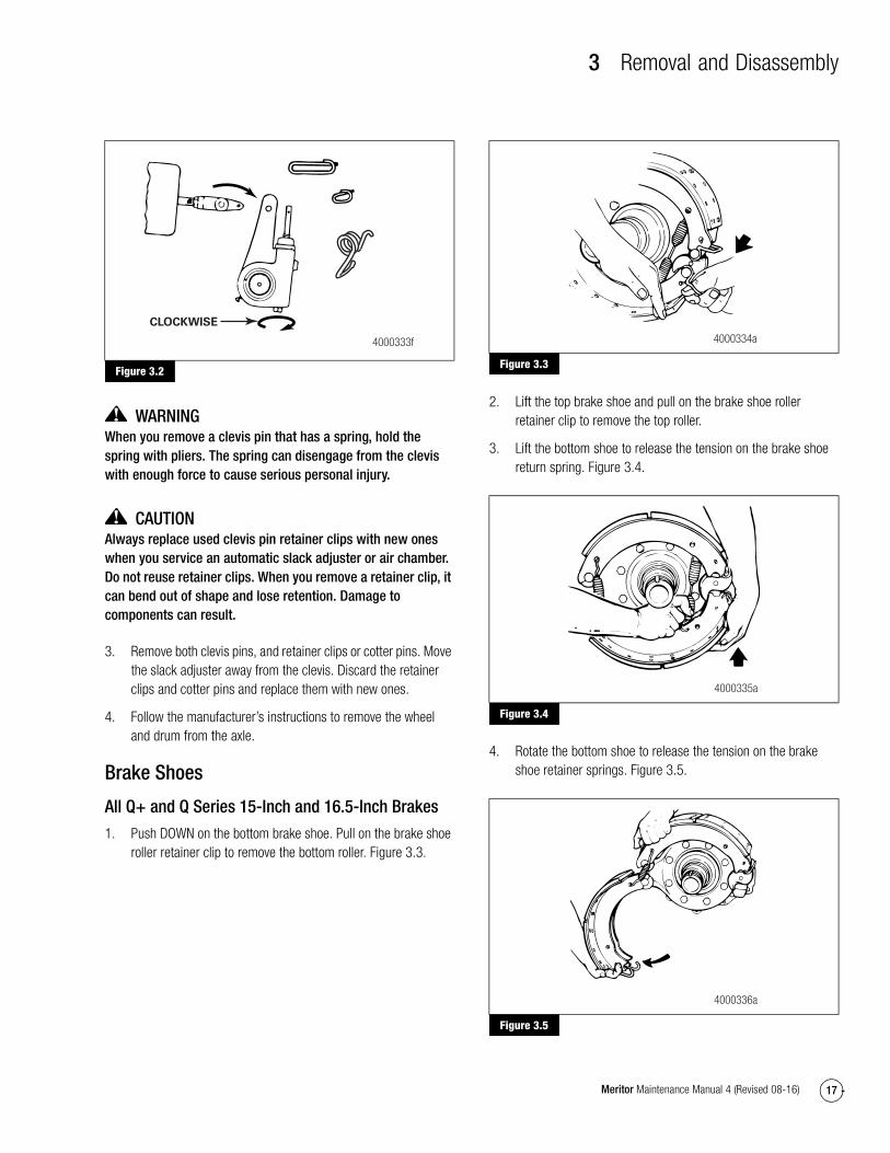
CAUTIONYou must disengage a pull pawl before rotating the manual adjusting nut, or you will damage the pawl teeth. A damaged pawl will not allow the slack adjuster to automatically adjust brake clearance. Replace damaged pawls before returning the vehicle to service to prevent damage to components.
1. Disengage the pull pawl. Use a screwdriver or equivalent tool to pry the pull pawl at least 1/32-inch (0.8 mm) to disengage the teeth from the actuator. Figure 3.1.
Figure 3.1
2. Use a wrench to turn the manual adjusting nut CLOCKWISE until the brake shoes are fully retracted, and the lining clears the drum. Figure 3.2.
Figure 3.1
PULL PAWLPRY UP
PAWL
4000331c
3 Removal and Disassembly
17Meritor Maintenance Manual 4 (Revised 08-16)
Figure 3.2
WARNINGWhen you remove a clevis pin that has a spring, hold the spring with pliers. The spring can disengage from the clevis with enough force to cause serious personal injury.
CAUTIONAlways replace used clevis pin retainer clips with new ones when you service an automatic slack adjuster or air chamber. Do not reuse retainer clips. When you remove a retainer clip, it can bend out of shape and lose retention. Damage to components can result.
3. Remove both clevis pins, and retainer clips or cotter pins. Move the slack adjuster away from the clevis. Discard the retainer clips and cotter pins and replace them with new ones.
4. Follow the manufacturer’s instructions to remove the wheel and drum from the axle.
Brake Shoes
All Q+ and Q Series 15-Inch and 16.5-Inch Brakes
1. Push DOWN on the bottom brake shoe. Pull on the brake shoe roller retainer clip to remove the bottom roller. Figure 3.3.
Figure 3.3
2. Lift the top brake shoe and pull on the brake shoe roller retainer clip to remove the top roller.
3. Lift the bottom shoe to release the tension on the brake shoe return spring. Figure 3.4.
Figure 3.4
4. Rotate the bottom shoe to release the tension on the brake shoe retainer springs. Figure 3.5.
Figure 3.5
Figure 3.2
CLOCKWISE
4000333f
Figure 3.3
Figure 3.4
Figure 3.5
4000334a
4000335a
4000336a
3 Removal and Disassembly
18 Meritor Maintenance Manual 4 (Revised 08-16)
5. Remove the shoe retainer springs and the brake shoes.
6. Use the correct bushing driver tool to remove the anchor pin bushings from the spider.
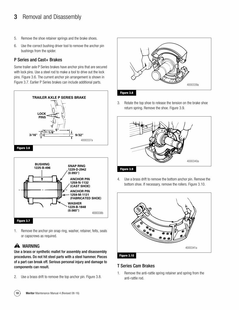
P Series and Cast+ Brakes
Some trailer axle P Series brakes have anchor pins that are secured with lock pins. Use a steel rod to make a tool to drive out the lock pins. Figure 3.6. The current anchor pin arrangement is shown in Figure 3.7. Earlier P Series brakes can include additional parts.
Figure 3.6
Figure 3.7
1. Remove the anchor pin snap ring, washer, retainer, felts, seals or capscrews as required.
WARNINGUse a brass or synthetic mallet for assembly and disassembly procedures. Do not hit steel parts with a steel hammer. Pieces of a part can break off. Serious personal injury and damage to components can result.
2. Use a brass drift to remove the top anchor pin. Figure 3.8.
Figure 3.8
3. Rotate the top shoe to release the tension on the brake shoe return spring. Remove the shoe. Figure 3.9.
Figure 3.9
4. Use a brass drift to remove the bottom anchor pin. Remove the bottom shoe. If necessary, remove the rollers. Figure 3.10.
Figure 3.10
T Series Cam Brakes
1. Remove the anti-rattle spring retainer and spring from the anti-rattle rod.
Figure 3.6
Figure 3.7
TRAILER AXLE P SERIES BRAKE
LOCKPINS
3/16" 9/32"1/8"
5"
4000337a
BUSHING1225-B-496
SNAP RING1229-D-2942(0.093")
ANCHOR PIN1259-N-1132(CAST SHOE)
ANCHOR PIN1259-M-1131(FABRICATED SHOE)
WASHER1229-B-1848(0.060")
4000338b
Figure 3.8
Figure 3.9
Figure 3.10
4000339a
4000340a
4000341a
3 Removal and Disassembly
19Meritor Maintenance Manual 4 (Revised 08-16)
2. Push DOWN on the bottom brake shoe to provide enough clearance to remove the bottom brake shoe roller. Remove the roller.
3. Lift the top brake shoe. Remove the top brake shoe roller. Remove the anchor pin snap ring and the anchor pin.
4. Rotate the bottom shoe to release the tension on the brake shoe retainer springs. Remove the shoe retainer springs and the brake shoes.
Check the Camshaft Bushing for Wear
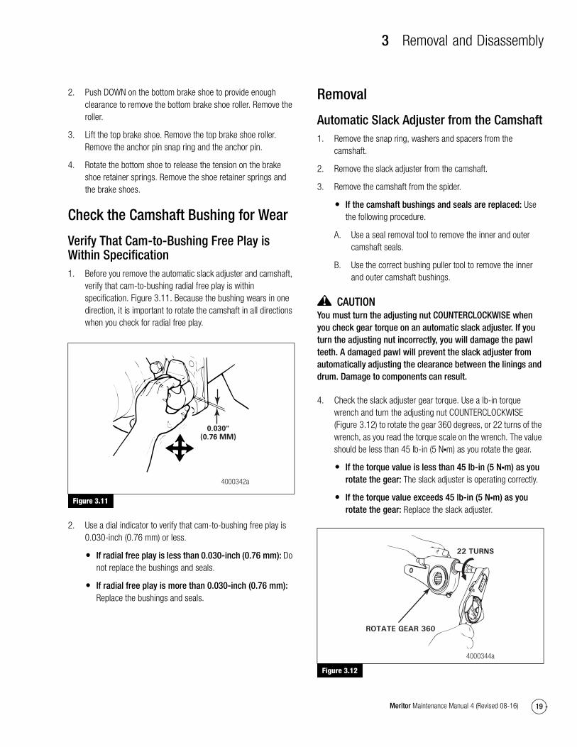
Verify That Cam-to-Bushing Free Play is Within Specification1. Before you remove the automatic slack adjuster and camshaft,
verify that cam-to-bushing radial free play is within specification. Figure 3.11. Because the bushing wears in one direction, it is important to rotate the camshaft in all directions when you check for radial free play.
Figure 3.11
2. Use a dial indicator to verify that cam-to-bushing free play is 0.030-inch (0.76 mm) or less.
� If radial free play is less than 0.030-inch (0.76 mm): Do not replace the bushings and seals.
� If radial free play is more than 0.030-inch (0.76 mm): Replace the bushings and seals.
Removal
Automatic Slack Adjuster from the Camshaft1. Remove the snap ring, washers and spacers from the
camshaft.
2. Remove the slack adjuster from the camshaft.
3. Remove the camshaft from the spider.
� If the camshaft bushings and seals are replaced: Use the following procedure.
A. Use a seal removal tool to remove the inner and outer camshaft seals.
B. Use the correct bushing puller tool to remove the inner and outer camshaft bushings.
CAUTIONYou must turn the adjusting nut COUNTERCLOCKWISE when you check gear torque on an automatic slack adjuster. If you turn the adjusting nut incorrectly, you will damage the pawl teeth. A damaged pawl will prevent the slack adjuster from automatically adjusting the clearance between the linings and drum. Damage to components can result.
4. Check the slack adjuster gear torque. Use a lb-in torque wrench and turn the adjusting nut COUNTERCLOCKWISE (Figure 3.12) to rotate the gear 360 degrees, or 22 turns of the wrench, as you read the torque scale on the wrench. The value should be less than 45 lb-in (5 N�m) as you rotate the gear.
� If the torque value is less than 45 lb-in (5 N�m) as you rotate the gear: The slack adjuster is operating correctly.
� If the torque value exceeds 45 lb-in (5 N�m) as you rotate the gear: Replace the slack adjuster.
Figure 3.12
Figure 3.11
4000342a
0.030"(0.76 MM)
Figure 3.12
22 TURNS
ROTATE GEAR 360
4000344a
3 Removal and Disassembly
20 Meritor Maintenance Manual 4 (Revised 08-16)
Disassembly
Automatic Slack Adjuster1. Use a punch and hammer to tap the metal boot retaining ring
from the slack adjuster housing.
2. Remove the boot from the housing. Pull the actuator assembly from the housing. Figure 3.13. Discard the boot, and install a new boot when you assemble the slack adjuster.
Figure 3.13
3. Use a small screwdriver to push down on one side of the piston retaining ring to force the ring out of the groove. Figure 3.14.
Figure 3.14
4. Extend the coils of the ring. Use pliers to unwind the ring and pull it out of the groove. Use a new ring when you assemble the slack adjuster. Figure 3.14.
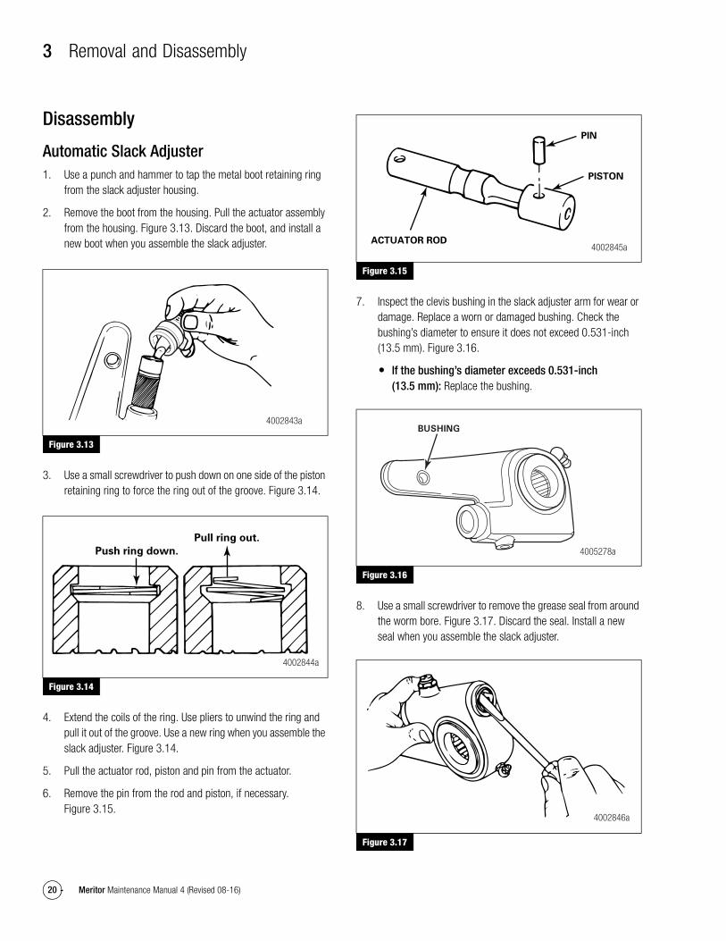
5. Pull the actuator rod, piston and pin from the actuator.
6. Remove the pin from the rod and piston, if necessary. Figure 3.15.
Figure 3.15
7. Inspect the clevis bushing in the slack adjuster arm for wear or damage. Replace a worn or damaged bushing. Check the bushing’s diameter to ensure it does not exceed 0.531-inch (13.5 mm). Figure 3.16.
� If the bushing’s diameter exceeds 0.531-inch (13.5 mm): Replace the bushing.
Figure 3.16
8. Use a small screwdriver to remove the grease seal from around the worm bore. Figure 3.17. Discard the seal. Install a new seal when you assemble the slack adjuster.
Figure 3.17
Figure 3.13
Figure 3.14
4002843a
Push ring down.
Pull ring out.
4002844a
Figure 3.15
Figure 3.16
Figure 3.17
PIN
PISTON
ACTUATOR ROD4002845a
4005278a
BUSHING
4002846a
4 Prepare Parts for Assembly
21Meritor Maintenance Manual 4 (Revised 08-16)
4 Prepare Parts for AssemblyHazard Alert MessagesRead and observe all Warning and Caution hazard alert messages in this publication. They provide information that can help prevent serious personal injury, damage to components, or both.
WARNINGTo prevent serious eye injury, always wear safe eye protection when you perform vehicle maintenance or service.
ASBESTOS AND NON-ASBESTOS FIBERS WARNING
Some brake linings contain asbestos fibers, a cancer and lung disease hazard. Some brake linings contain non-asbestos fibers, whose long-term effects to health are unknown. You must use caution when you handle both asbestos and non-asbestos materials.
Clean, Dry and Inspect Parts
WARNINGSolvent cleaners can be flammable, poisonous and cause burns. Examples of solvent cleaners are carbon tetrachloride, and emulsion-type and petroleum-base cleaners. Read the manufacturer’s instructions before using a solvent cleaner, then carefully follow the instructions. Also follow the procedures below.
� Wear safe eye protection.
� Wear clothing that protects your skin.
� Work in a well-ventilated area.
� Do not use gasoline or solvents that contain gasoline. Gasoline can explode.
� You must use hot solution tanks or alkaline solutions correctly. Read the manufacturer’s instructions before using hot solution tanks and alkaline solutions. Then carefully follow the instructions.
CAUTIONDo not use hot solution tanks or water and alkaline solutions to clean ground or polished parts. Damage to parts can result.
Use soap and water to clean non-metal parts.
Dry parts immediately after cleaning with soft, clean paper or cloth, or compressed air.
Corrosion ProtectionIf you assemble the parts immediately after you clean them, lubricate the parts with grease to prevent corrosion. Parts must be clean and dry before you lubricate them.
If you store the parts after you clean them, apply a corrosion-preventive material. Store the parts in a special paper or other material that prevents corrosion.
Inspect Parts
BrakesCheck the spider for expanded anchor pin holes and for cracks. Replace damaged spiders and anchor pin bushings.
Check the camshaft bracket for broken welds, cracks and correct alignment. Replace damaged brackets.
Check the anchor pins for corrosion and wear. Replace worn or damaged anchor pins.
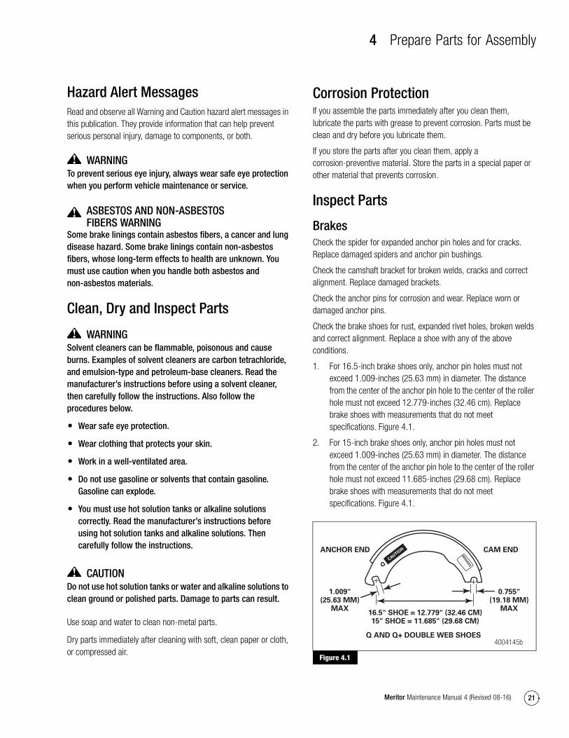
Check the brake shoes for rust, expanded rivet holes, broken welds and correct alignment. Replace a shoe with any of the above conditions.
1. For 16.5-inch brake shoes only, anchor pin holes must not exceed 1.009-inches (25.63 mm) in diameter. The distance from the center of the anchor pin hole to the center of the roller hole must not exceed 12.779-inches (32.46 cm). Replace brake shoes with measurements that do not meet specifications. Figure 4.1.
2. For 15-inch brake shoes only, anchor pin holes must not exceed 1.009-inches (25.63 mm) in diameter. The distance from the center of the anchor pin hole to the center of the roller hole must not exceed 11.685-inches (29.68 cm). Replace brake shoes with measurements that do not meet specifications. Figure 4.1.
Figure 4.1
Figure 4.1
4004145b
CAM ENDANCHOR END
1.009"(25.63 MM)
MAX
0.755"(19.18 MM)
MAX16.5" SHOE = 12.779" (32.46 CM)15" SHOE = 11.685" (29.68 CM)
Q AND Q+ DOUBLE WEB SHOES
4 Prepare Parts for Assembly
22 Meritor Maintenance Manual 4 (Revised 08-16)
Brake Drums
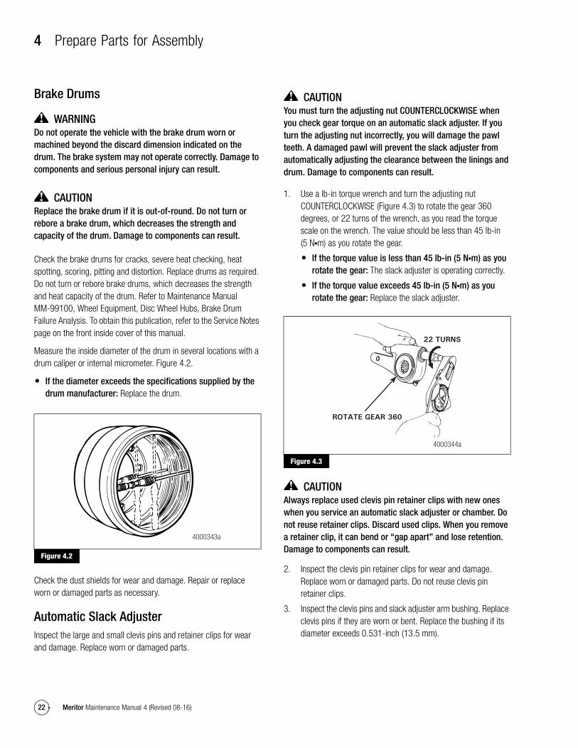
WARNINGDo not operate the vehicle with the brake drum worn or machined beyond the discard dimension indicated on the drum. The brake system may not operate correctly. Damage to components and serious personal injury can result.
CAUTIONReplace the brake drum if it is out-of-round. Do not turn or rebore a brake drum, which decreases the strength and capacity of the drum. Damage to components can result.
Check the brake drums for cracks, severe heat checking, heat spotting, scoring, pitting and distortion. Replace drums as required. Do not turn or rebore brake drums, which decreases the strength and heat capacity of the drum. Refer to Maintenance Manual MM-99100, Wheel Equipment, Disc Wheel Hubs, Brake Drum Failure Analysis. To obtain this publication, refer to the Service Notes page on the front inside cover of this manual.
Measure the inside diameter of the drum in several locations with a drum caliper or internal micrometer. Figure 4.2.
� If the diameter exceeds the specifications supplied by the drum manufacturer: Replace the drum.
Figure 4.2
Check the dust shields for wear and damage. Repair or replace worn or damaged parts as necessary.
Automatic Slack AdjusterInspect the large and small clevis pins and retainer clips for wear and damage. Replace worn or damaged parts.
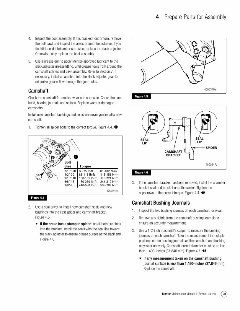
CAUTIONYou must turn the adjusting nut COUNTERCLOCKWISE when you check gear torque on an automatic slack adjuster. If you turn the adjusting nut incorrectly, you will damage the pawl teeth. A damaged pawl will prevent the slack adjuster from automatically adjusting the clearance between the linings and drum. Damage to components can result.
1. Use a lb-in torque wrench and turn the adjusting nut COUNTERCLOCKWISE (Figure 4.3) to rotate the gear 360 degrees, or 22 turns of the wrench, as you read the torque scale on the wrench. The value should be less than 45 lb-in (5 N�m) as you rotate the gear.
� If the torque value is less than 45 lb-in (5 N�m) as you rotate the gear: The slack adjuster is operating correctly.
� If the torque value exceeds 45 lb-in (5 N�m) as you rotate the gear: Replace the slack adjuster.
Figure 4.3
CAUTIONAlways replace used clevis pin retainer clips with new ones when you service an automatic slack adjuster or chamber. Do not reuse retainer clips. Discard used clips. When you remove a retainer clip, it can bend or “gap apart” and lose retention. Damage to components can result.
2. Inspect the clevis pin retainer clips for wear and damage. Replace worn or damaged parts. Do not reuse clevis pin retainer clips.
3. Inspect the clevis pins and slack adjuster arm bushing. Replace clevis pins if they are worn or bent. Replace the bushing if its diameter exceeds 0.531-inch (13.5 mm).
Figure 4.2
4000343a
Figure 4.3
22 TURNS
ROTATE GEAR 360
4000344a
4 Prepare Parts for Assembly
23Meritor Maintenance Manual 4 (Revised 08-16)
4. Inspect the boot assembly. If it is cracked, cut or torn, remove the pull pawl and inspect the areas around the actuator. If you find dirt, solid lubricant or corrosion, replace the slack adjuster. Otherwise, only replace the boot assembly.
5. Use a grease gun to apply Meritor-approved lubricant to the slack adjuster grease fitting, until grease flows from around the camshaft splines and pawl assembly. Refer to Section 7. If necessary, install a camshaft into the slack adjuster gear to minimize grease flow through the gear holes.
CamshaftCheck the camshaft for cracks, wear and corrosion. Check the cam head, bearing journals and splines. Replace worn or damaged camshafts.
Install new camshaft bushings and seals whenever you install a new camshaft.
1. Tighten all spider bolts to the correct torque. Figure 4.4. @
Figure 4.4
2. Use a seal driver to install new camshaft seals and new bushings into the cast spider and camshaft bracket. Figure 4.5.
� If the brake has a stamped spider: Install both bushings into the bracket. Install the seals with the seal lips toward the slack adjuster to ensure grease purges at the slack end. Figure 4.6.
Figure 4.5
Figure 4.6
3. If the camshaft bracket has been removed, install the chamber bracket seal and bracket onto the spider. Tighten the capscrews to the correct torque. Figure 4.4. @
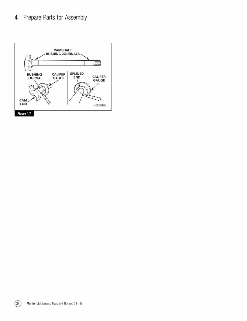
Camshaft Bushing Journals1. Inspect the two bushing journals on each camshaft for wear.
2. Remove any debris from the camshaft bushing journals to ensure an accurate measurement.
3. Use a 1-2-inch machinist’s caliper to measure the bushing journals on each camshaft. Take the measurement in multiple positions on the bushing journals as the camshaft and bushing may wear unevenly. Camshaft journal diameter must be no less than 1.490-inches (37.846 mm). Figure 4.7. @
� If any measurement taken on the camshaft bushing journal surface is less than 1.490-inches (37.846 mm): Replace the camshaft.
Figure 4.4
Bolt Size Torque
7/16"-20 60-75 lb-ft 81-102 N•m1/2"-20 85-115 lb-ft 115-156 N•m9/16"-18 130-165 lb-ft 176-224 N•m5/8"-18 180-230 lb-ft 244-312 N•m7/8"-9 440-580 lb-ft 598-789 N•m
4000345a
Figure 4.5
Figure 4.6
4000346a
SPIDER
CAMSHAFTBRACKET
SEALLIP
SEALLIP
4000347a
4 Prepare Parts for Assembly
24 Meritor Maintenance Manual 4 (Revised 08-16)
Figure 4.7
Figure 4.7
4009916a
CAMSHAFTBUSHING JOURNALS
CALIPERGAUGE
CALIPERGAUGE
SPLINEDEND
BUSHINGJOURNAL
CAMEND
5 Assembly and Installation
25Meritor Maintenance Manual 4 (Revised 08-16)
5 Assembly and InstallationHazard Alert MessagesRead and observe all Warning and Caution hazard alert messages in this publication. They provide information that can help prevent serious personal injury, damage to components, or both.
WARNINGTo prevent serious eye injury, always wear safe eye protection when you perform vehicle maintenance or service.
Use the correct shoe return spring with the Q+ camshaft. An incorrect shoe spring can interfere with the camshaft and affect braking performance. Serious personal injury and damage to components can result.
ASBESTOS AND NON-ASBESTOS FIBERS WARNING
Some brake linings contain asbestos fibers, a cancer and lung disease hazard. Some brake linings contain non-asbestos fibers, whose long-term effects to health are unknown. You must use caution when you handle both asbestos and non-asbestos materials.
CAUTIONOnly install a Q+ camshaft in a Q+ brake. A Q Series hammerclaw camshaft will not provide enough clearance between the brake shoe and the brake drum. Brake drag and damage to components can result.
To install a new brake drum so that it fits correctly over a Q+ brake shoe, you must install a Q+ camshaft to prevent damage to components.
Assembly
Automatic Slack AdjusterSince January 1993, some parts of Meritor automatic slack adjusters are not serviceable or interchangeable with parts from earlier models. Refer to Section 1 for more information.
Never mix automatic slack adjusters on the same axle. Always use replacement parts that were originally designed for the brake system to help ensure maximum brake performance.
1. Remove any corrosion-preventive material that may have been applied to the parts you will assemble.
2. Use grease to lubricate the gear bore in the housing.
3. Lubricate the worm gear seal with grease that meets Meritor specifications. Press the seal into its groove. Push the gear into the housing.
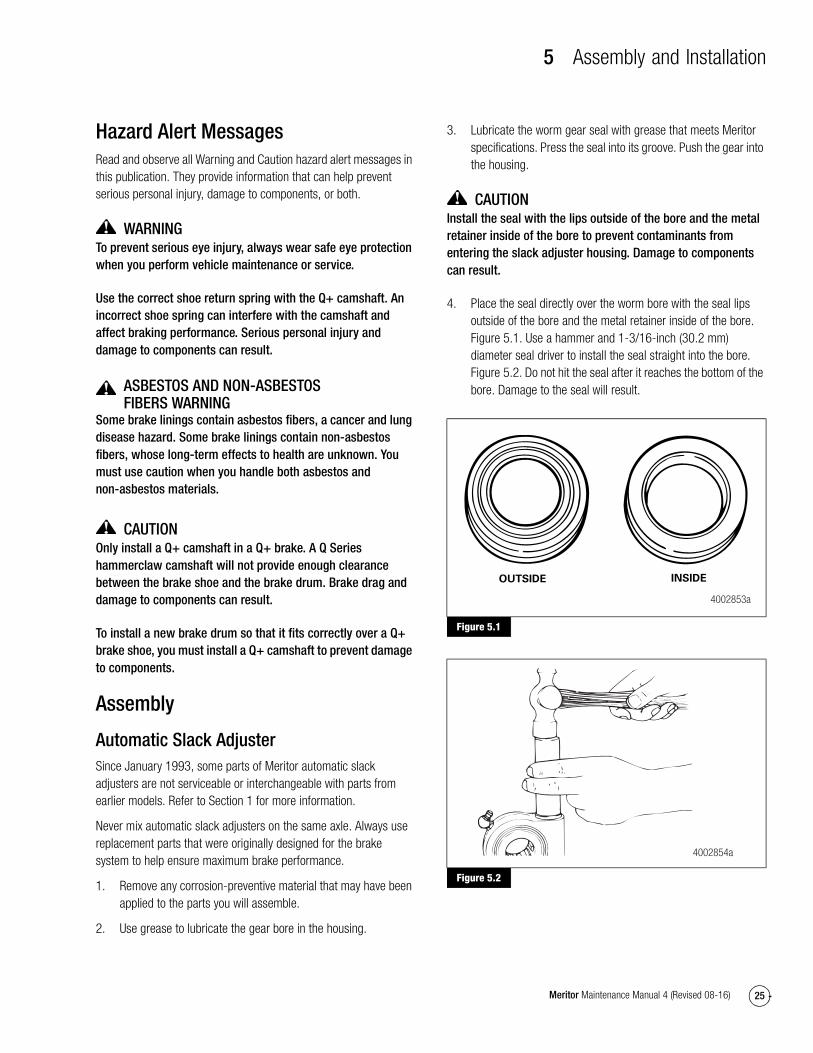
CAUTIONInstall the seal with the lips outside of the bore and the metal retainer inside of the bore to prevent contaminants from entering the slack adjuster housing. Damage to components can result.
4. Place the seal directly over the worm bore with the seal lips outside of the bore and the metal retainer inside of the bore. Figure 5.1. Use a hammer and 1-3/16-inch (30.2 mm) diameter seal driver to install the seal straight into the bore. Figure 5.2. Do not hit the seal after it reaches the bottom of the bore. Damage to the seal will result.
Figure 5.1
Figure 5.2
Figure 5.1
Figure 5.2
4002853a
OUTSIDE INSIDE
4002854a

5 Assembly and Installation
26 Meritor Maintenance Manual 4 (Revised 08-16)
5. If you removed the pin, install it into the rod and piston. Figure 5.3.
Figure 5.3
6. Apply a small amount of grease to the actuator piston and install the actuator rod and piston assembly into the actuator adjusting sleeve.
7. Slide the piston retaining ring over the rod.
8. Extend the coils of the ring.
9. Use a small screwdriver to press one end of the ring into the groove. Figure 5.4.
Figure 5.4
10. Keep the coil extended. Press on the ring and work around the groove until the ring is in the groove completely.
11. Check to ensure that the ring is installed correctly in the groove. You cannot pull the piston out of the actuator if the retaining ring is installed correctly.
12. Disengage the pull pawl. Use a screwdriver or equivalent tool to pry the pull pawl at least 1/32-inch (0.8 mm) to disengage the teeth from the actuator.
13. Make certain the pull pawl is disengaged, and install the actuator assembly into the housing so that the actuator slides along the worm splines.
14. Fill the boot with grease and slip it over the actuator rod. Do not seal the boot to the tapered part of the actuator rod. The top of the boot must fit into the groove.
15. Press the boot metal ring into the slack adjuster housing.
16. Remove the screwdriver or equivalent tool from the pull pawl. The pull pawl will re-engage automatically.
17. Refer to Section 7 for slack adjuster inspection and lubrication.
Installation
Camshaft1. Install the cam head thrust washer onto the camshaft. Apply
Meritor-approved grease to the camshaft bushings and journals, and seal lips. Refer to Section 7.
2. Install the camshaft through the spider and bracket so that the camshaft turns freely by hand. Figure 5.5.
Figure 5.5
Figure 5.3
Figure 5.4
4002855a
PIN
PISTON
ACTUATOR ROD
4002856a
START BOTTOM COIL RING IN GROOVE
Figure 5.5
4000348a
5 Assembly and Installation
27Meritor Maintenance Manual 4 (Revised 08-16)
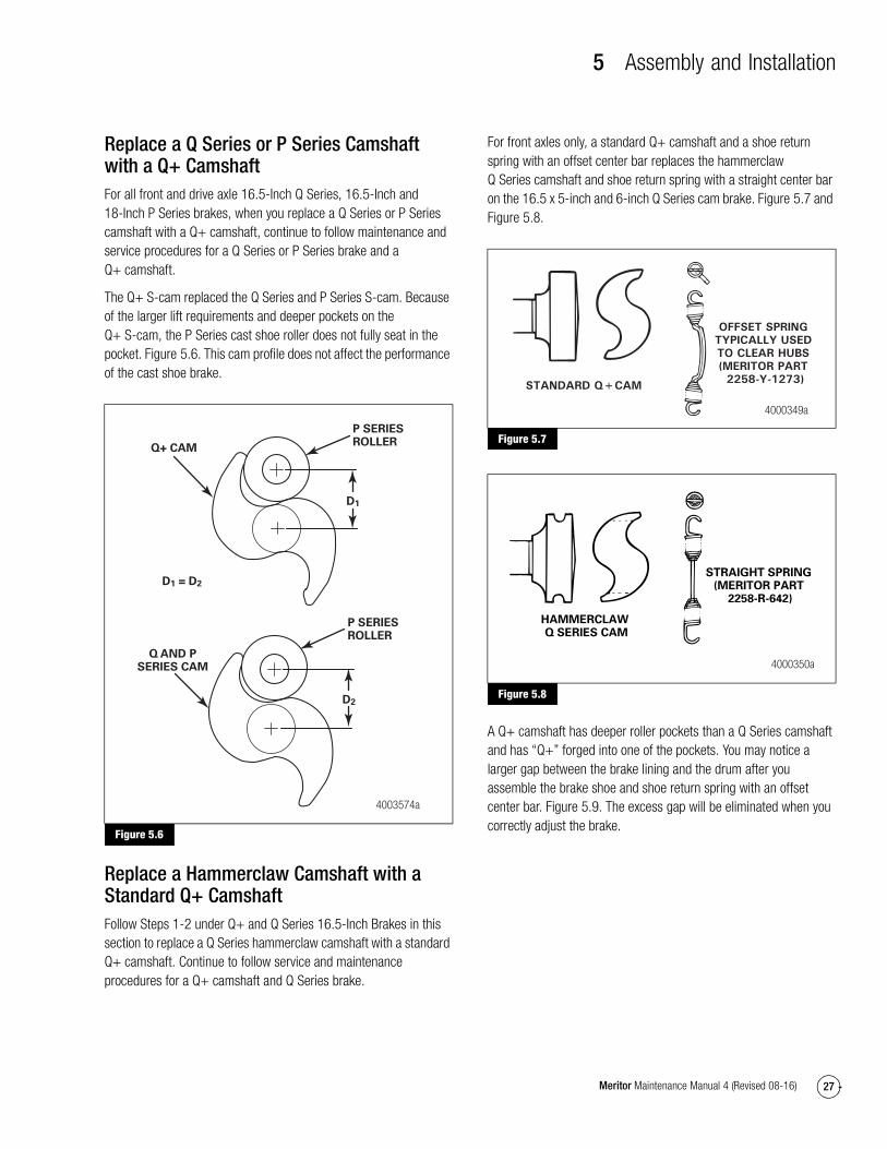
Replace a Q Series or P Series Camshaft with a Q+ CamshaftFor all front and drive axle 16.5-Inch Q Series, 16.5-Inch and 18-Inch P Series brakes, when you replace a Q Series or P Series camshaft with a Q+ camshaft, continue to follow maintenance and service procedures for a Q Series or P Series brake and a Q+ camshaft.
The Q+ S-cam replaced the Q Series and P Series S-cam. Because of the larger lift requirements and deeper pockets on the Q+ S-cam, the P Series cast shoe roller does not fully seat in the pocket. Figure 5.6. This cam profile does not affect the performance of the cast shoe brake.
Figure 5.6
Replace a Hammerclaw Camshaft with a Standard Q+ CamshaftFollow Steps 1-2 under Q+ and Q Series 16.5-Inch Brakes in this section to replace a Q Series hammerclaw camshaft with a standard Q+ camshaft. Continue to follow service and maintenance procedures for a Q+ camshaft and Q Series brake.
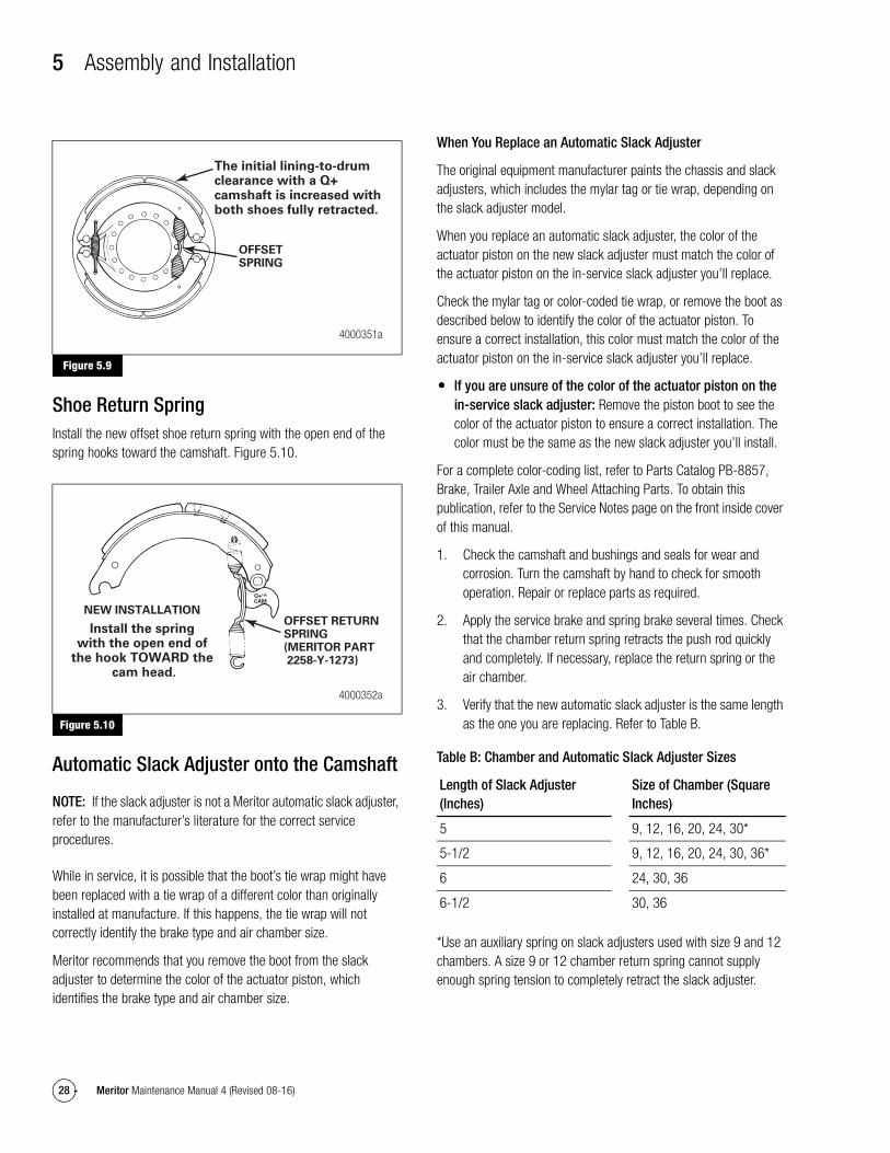
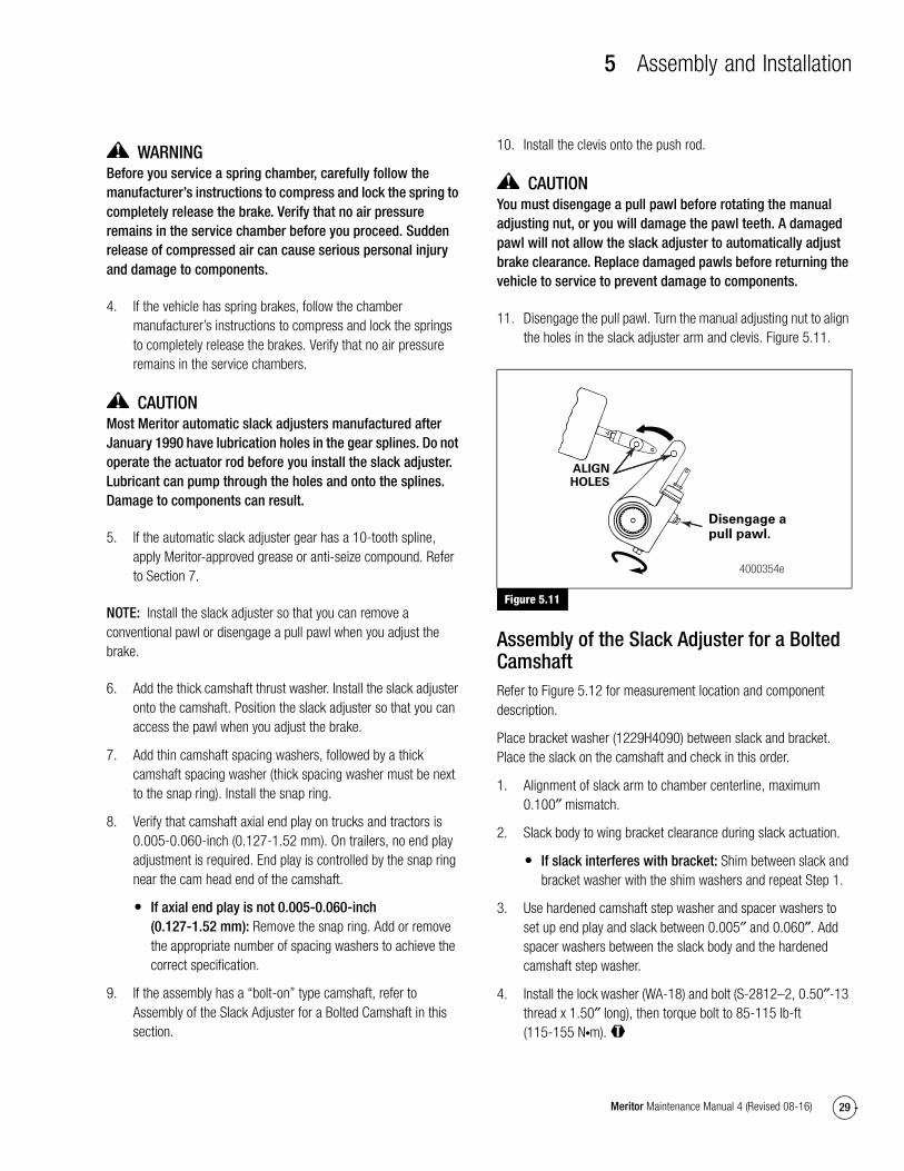
For front axles only, a standard Q+ camshaft and a shoe return spring with an offset center bar replaces the hammerclaw Q Series camshaft and shoe return spring with a straight center bar on the 16.5 x 5-inch and 6-inch Q Series cam brake. Figure 5.7 and Figure 5.8.
Figure 5.7
Figure 5.8
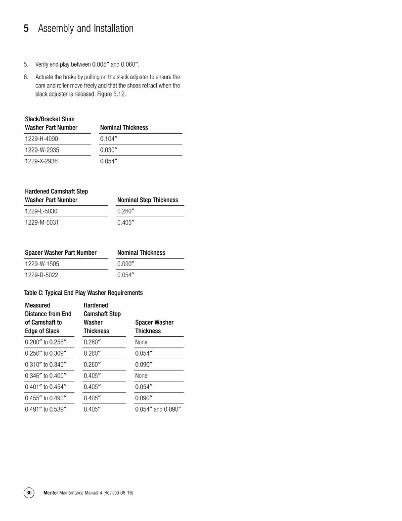
A Q+ camshaft has deeper roller pockets than a Q Series camshaft and has “Q+” forged into one of the pockets. You may notice a larger gap between the brake lining and the drum after you assemble the brake shoe and shoe return spring with an offset center bar. Figure 5.9. The excess gap will be eliminated when you correctly adjust the brake.
Figure 5.6
Q AND PSERIES CAM
P SERIESROLLER
P SERIESROLLER
Q+ CAM
4003574a
D1
D2
D1 = D2
Figure 5.7
Figure 5.8
STANDARD Q+CAM
OFFSET SPRINGTYPICALLY USEDTO CLEAR HUBS(MERITOR PART 2258-Y-1273)
4000349a
HAMMERCLAW Q SERIES CAM
STRAIGHT SPRING(MERITOR PART
2258-R-642)
4000350a
5 Assembly and Installation
28 Meritor Maintenance Manual 4 (Revised 08-16)
Figure 5.9
Shoe Return SpringInstall the new offset shoe return spring with the open end of the spring hooks toward the camshaft. Figure 5.10.
Figure 5.10
Automatic Slack Adjuster onto the Camshaft
NOTE: If the slack adjuster is not a Meritor automatic slack adjuster, refer to the manufacturer’s literature for the correct service procedures.
While in service, it is possible that the boot’s tie wrap might have been replaced with a tie wrap of a different color than originally installed at manufacture. If this happens, the tie wrap will not correctly identify the brake type and air chamber size.
Meritor recommends that you remove the boot from the slack adjuster to determine the color of the actuator piston, which identifies the brake type and air chamber size.
When You Replace an Automatic Slack Adjuster
The original equipment manufacturer paints the chassis and slack adjusters, which includes the mylar tag or tie wrap, depending on the slack adjuster model.
When you replace an automatic slack adjuster, the color of the actuator piston on the new slack adjuster must match the color of the actuator piston on the in-service slack adjuster you’ll replace.
Check the mylar tag or color-coded tie wrap, or remove the boot as described below to identify the color of the actuator piston. To ensure a correct installation, this color must match the color of the actuator piston on the in-service slack adjuster you’ll replace.
� If you are unsure of the color of the actuator piston on the in-service slack adjuster: Remove the piston boot to see the color of the actuator piston to ensure a correct installation. The color must be the same as the new slack adjuster you’ll install.
For a complete color-coding list, refer to Parts Catalog PB-8857, Brake, Trailer Axle and Wheel Attaching Parts. To obtain this publication, refer to the Service Notes page on the front inside cover of this manual.
1. Check the camshaft and bushings and seals for wear and corrosion. Turn the camshaft by hand to check for smooth operation. Repair or replace parts as required.
2. Apply the service brake and spring brake several times. Check that the chamber return spring retracts the push rod quickly and completely. If necessary, replace the return spring or the air chamber.
3. Verify that the new automatic slack adjuster is the same length as the one you are replacing. Refer to Table B.
Table B: Chamber and Automatic Slack Adjuster Sizes
*Use an auxiliary spring on slack adjusters used with size 9 and 12 chambers. A size 9 or 12 chamber return spring cannot supply enough spring tension to completely retract the slack adjuster.
Figure 5.9
Figure 5.10
The initial lining-to-drum clearance with a Q+ camshaft is increased with both shoes fully retracted.
OFFSETSPRING
4000351a
NEW INSTALLATION
Install the spring with the open end of
the hook TOWARD the cam head.
Q+TM
CAM
OFFSET RETURNSPRING(MERITOR PART 2258-Y-1273)
4000352a
Length of Slack Adjuster (Inches)
Size of Chamber (Square Inches)
5 9, 12, 16, 20, 24, 30*
5-1/2 9, 12, 16, 20, 24, 30, 36*
6 24, 30, 36
6-1/2 30, 36
5 Assembly and Installation
29Meritor Maintenance Manual 4 (Revised 08-16)
WARNINGBefore you service a spring chamber, carefully follow the manufacturer’s instructions to compress and lock the spring to completely release the brake. Verify that no air pressure remains in the service chamber before you proceed. Sudden release of compressed air can cause serious personal injury and damage to components.
4. If the vehicle has spring brakes, follow the chamber manufacturer’s instructions to compress and lock the springs to completely release the brakes. Verify that no air pressure remains in the service chambers.
CAUTIONMost Meritor automatic slack adjusters manufactured after January 1990 have lubrication holes in the gear splines. Do not operate the actuator rod before you install the slack adjuster. Lubricant can pump through the holes and onto the splines. Damage to components can result.
5. If the automatic slack adjuster gear has a 10-tooth spline, apply Meritor-approved grease or anti-seize compound. Refer to Section 7.
NOTE: Install the slack adjuster so that you can remove a conventional pawl or disengage a pull pawl when you adjust the brake.
6. Add the thick camshaft thrust washer. Install the slack adjuster onto the camshaft. Position the slack adjuster so that you can access the pawl when you adjust the brake.
7. Add thin camshaft spacing washers, followed by a thick camshaft spacing washer (thick spacing washer must be next to the snap ring). Install the snap ring.
8. Verify that camshaft axial end play on trucks and tractors is 0.005-0.060-inch (0.127-1.52 mm). On trailers, no end play adjustment is required. End play is controlled by the snap ring near the cam head end of the camshaft.
� If axial end play is not 0.005-0.060-inch (0.127-1.52 mm): Remove the snap ring. Add or remove the appropriate number of spacing washers to achieve the correct specification.
9. If the assembly has a “bolt-on” type camshaft, refer to Assembly of the Slack Adjuster for a Bolted Camshaft in this section.
10. Install the clevis onto the push rod.
CAUTIONYou must disengage a pull pawl before rotating the manual adjusting nut, or you will damage the pawl teeth. A damaged pawl will not allow the slack adjuster to automatically adjust brake clearance. Replace damaged pawls before returning the vehicle to service to prevent damage to components.
11. Disengage the pull pawl. Turn the manual adjusting nut to align the holes in the slack adjuster arm and clevis. Figure 5.11.
Figure 5.11
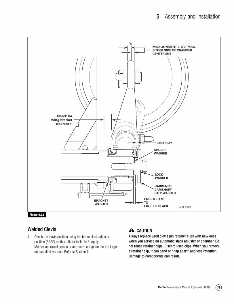
Assembly of the Slack Adjuster for a Bolted CamshaftRefer to Figure 5.12 for measurement location and component description.
Place bracket washer (1229H4090) between slack and bracket. Place the slack on the camshaft and check in this order.
1. Alignment of slack arm to chamber centerline, maximum 0.100″ mismatch.
2. Slack body to wing bracket clearance during slack actuation.
� If slack interferes with bracket: Shim between slack and bracket washer with the shim washers and repeat Step 1.
3. Use hardened camshaft step washer and spacer washers to set up end play and slack between 0.005″ and 0.060″. Add spacer washers between the slack body and the hardened camshaft step washer.
4. Install the lock washer (WA-18) and bolt (S-2812–2, 0.50″-13 thread x 1.50″ long), then torque bolt to 85-115 lb-ft (115-155 N�m). @
Figure 5.11
ALIGNHOLES
Disengage a pull pawl.
4000354e
5 Assembly and Installation
30 Meritor Maintenance Manual 4 (Revised 08-16)
5. Verify end play between 0.005″ and 0.060″.
6. Actuate the brake by pulling on the slack adjuster to ensure the cam and roller move freely and that the shoes retract when the slack adjuster is released. Figure 5.12.
Table C: Typical End Play Washer Requirements
Slack/Bracket Shim Washer Part Number Nominal Thickness
1229-H-4090 0.104″
1229-W-2935 0.030″
1229-X-2936 0.054″
Hardened Camshaft Step Washer Part Number Nominal Step Thickness
1229-L-5030 0.260″
1229-M-5031 0.405″
Spacer Washer Part Number Nominal Thickness
1229-W-1505 0.090″
1229-D-5022 0.054″
Measured Distance from End of Camshaft to Edge of Slack
Hardened Camshaft Step Washer Thickness
Spacer Washer Thickness
0.200″ to 0.255″ 0.260″ None
0.256″ to 0.309″ 0.260″ 0.054″
0.310″ to 0.345″ 0.260″ 0.090″
0.346″ to 0.400″ 0.405″ None
0.401″ to 0.454″ 0.405″ 0.054″
0.455″ to 0.490″ 0.405″ 0.090″
0.491″ to 0.539″ 0.405″ 0.054″ and 0.090″
5 Assembly and Installation
31Meritor Maintenance Manual 4 (Revised 08-16)
Figure 5.12
Welded Clevis1. Check the clevis position using the brake slack adjuster
position (BSAP) method. Refer to Table E. Apply Meritor-approved grease or anti-seize compound to the large and small clevis pins. Refer to Section 7.
CAUTIONAlways replace used clevis pin retainer clips with new ones when you service an automatic slack adjuster or chamber. Do not reuse retainer clips. Discard used clips. When you remove a retainer clip, it can bend or “gap apart” and lose retention. Damage to components can result.
Figure 5.12
4006240a
END PLAY
LOCKWASHER
HARDENEDCAMSHAFTSTEP WASHER
END OF CAMTOEDGE OF SLACK
BRACKETWASHER
SPACERWASHER
Check forwing bracket
clearance.
MISALIGNMENT 0.100” MAX. EITHER SIDE OF CHAMBER CENTERLINE

5 Assembly and Installation
32 Meritor Maintenance Manual 4 (Revised 08-16)
2. Install new clevis pin retainer clips or cotter pins to secure the clevis pins. Retainer clips must be fully installed and positioned around the side of the clevis pin. Figure 5.13.
Figure 5.13
Threaded ClevisThe threaded-type clevis is available in two different pin spacings, 1.30-inches (33 mm) and 1.38-inches (35 mm). Figure 5.14. Based on your pin spacing, install the threaded clevis to the correct position using the template or brake slack adjuster position (BSAP) method. Refer to Table E.
Figure 5.14
Verify That the Slack Adjuster Angle is CorrectThere are two methods for determining the correct geometry for the slack adjuster.
A. Brake Slack Adjuster Position (BSAP)
B. Template
Trucks and Tractors Equipped with Standard-Stroke or Long-Stroke Chambers
For trucks and tractors and trailers equipped with drum brakes and standard- or long-stroke chambers, you can use either the brake slack adjuster position (BSAP) method or the template method to verify that the slack adjuster installed angle is correct. Refer to Brake Slack Adjuster Position (BSAP) Method and Table E, Meritor Automatic Slack Adjuster Installation, in this section.
Trailers Equipped with Standard-Stroke or Long-Stroke Chambers
The BSAP procedure is not used on trailers with drum brakes. Use the template method to verify that the slack adjuster installed angle is correct.
To order Meritor automatic slack adjuster templates, refer to the Service Notes page on the front inside cover of this manual.
Figure 5.13
CLEVISLARGE CLEVIS PIN
ANDRETAINER CLIP
ACTUATORROD
SMALL CLEVIS PINAND RETAINER CLIP
LARGE CLEVIS PINRETAINER CLIP
P/N 2257-D-1174
SMALL CLEVIS PINRETAINER CLIP
P/N 2257-C-1173
The clevis pin retainerclips must be fully installed and positioned around the SIDE of theclevis pin.
4001487a
Figure 5.14
4005004a
CLEVIS WITH1.38" PIN SPACINGCLEVIS WITH
1.30" PIN SPACING
There is a 0.080" (2.03 mm) differencebetween the large and small clevis holes.Notice the large pin is engaged and the
small pin is 0.080" (2.03 mm) off.
Clevis (1.38")Pin Spacing
Clevis (1.30")Pin Spacing
1.38"1.30"
5 Assembly and Installation
33Meritor Maintenance Manual 4 (Revised 08-16)
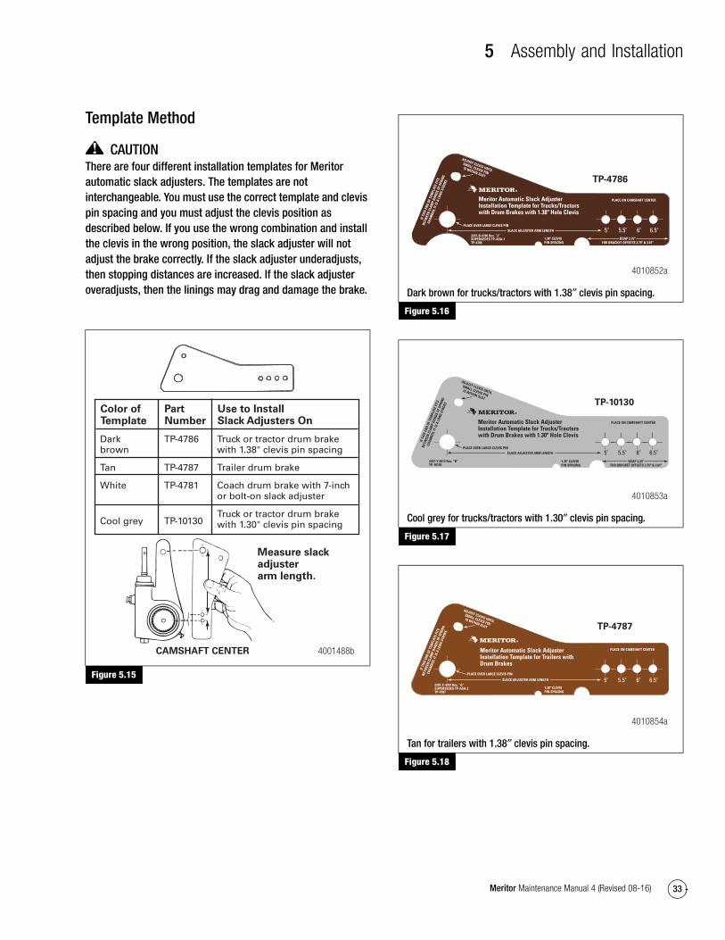
Template Method
CAUTIONThere are four different installation templates for Meritor automatic slack adjusters. The templates are not interchangeable. You must use the correct template and clevis pin spacing and you must adjust the clevis position as described below. If you use the wrong combination and install the clevis in the wrong position, the slack adjuster will not adjust the brake correctly. If the slack adjuster underadjusts, then stopping distances are increased. If the slack adjuster overadjusts, then the linings may drag and damage the brake.
Figure 5.15
Figure 5.16
Figure 5.17
Figure 5.18
Figure 5.15
Measure slack adjuster arm length.
CAMSHAFT CENTER
Color ofTemplate
Darkbrown
Tan
White
Cool grey
PartNumber
TP-4786
TP-4787
TP-4781
TP-10130
Use to InstallSlack Adjusters On
Truck or tractor drum brakewith 1.38" clevis pin spacing
Trailer drum brake
Coach drum brake with 7-inch or bolt-on slack adjuster
Truck or tractor drum brake with 1.30" clevis pin spacing
4001488b
Figure 5.16
Dark brown for trucks/tractors with 1.38″ clevis pin spacing.
Figure 5.17
Cool grey for trucks/tractors with 1.30″ clevis pin spacing.
Figure 5.18
Tan for trailers with 1.38″ clevis pin spacing.
4010852a
TP-4786
Meritor Automatic Slack Adjuster Installation Template for Trucks/Tractors with Drum Brakes with 1.38" Hole Clevis
5" 5.5" 6" 6.5"2297-B-4786 Rev. ”J“SUPERSEDES TP-ASA-1TP-4786
1.38" CLEVISPIN SPACING
BSAP 2.75"FOR BRACKET OFFSETS 3.75" & 3.81"
PLACE ON CAMSHAFT CENTER
ADJUST CLEVIS UNTIL
SMALL CLEVIS PINIS WITHIN SLOT
IF T
HIS
END
OF T
EMPL
ATE
FITS
BETW
EEN
CLA
MP
BAN
DS O
F SP
RIN
G
CHAM
BER,
IT IS
A L
ONG
STRO
KE
PLACE OVER LARGE CLEVIS PINSLACK ADJUSTER ARM LENGTH
4010853a
TP-10130
Meritor Automatic Slack Adjuster Installation Template for Trucks/Tractors with Drum Brakes with 1.30" Hole Clevis
5" 5.5" 6" 6.5"2297-Y-8813 Rev. ”B“TP-10130
1.30" CLEVISPIN SPACING
BSAP 2.25"FOR BRACKET OFFSETS 3.75" & 3.81"
PLACE ON CAMSHAFT CENTER
ADJUST CLEVIS UNTIL
SMALL CLEVIS PINIS WITHIN SLOT
IF T
HIS
END
OF T
EMPL
ATE
FITS
BETW
EEN
CLA
MP
BAN
DS O
F SP
RIN
G
CHAM
BER,
IT IS
A L
ONG
STRO
KEPLACE OVER LARGE CLEVIS PIN
SLACK ADJUSTER ARM LENGTH
4010854a
TP-4787
5" 5.5" 6" 6.5"2297-C-4787 Rev. ”G“SUPERSEDES TP-ASA-2TP-4787
1.38" CLEVISPIN SPACING
Meritor Automatic Slack Adjuster Installation Template for Trailers with Drum Brakes
ADJUST CLEVIS UNTIL
SMALL CLEVIS PINIS WITHIN SLOT
IF T
HIS
END
OF T
EMPL
ATE
FITS
BETW
EEN
CLA
MP
BAN
DS O
F SP
RIN
G
CHAM
BER,
IT IS
A L
ONG
STRO
KE
PLACE ON CAMSHAFT CENTER
PLACE OVER LARGE CLEVIS PIN
SLACK ADJUSTER ARM LENGTH
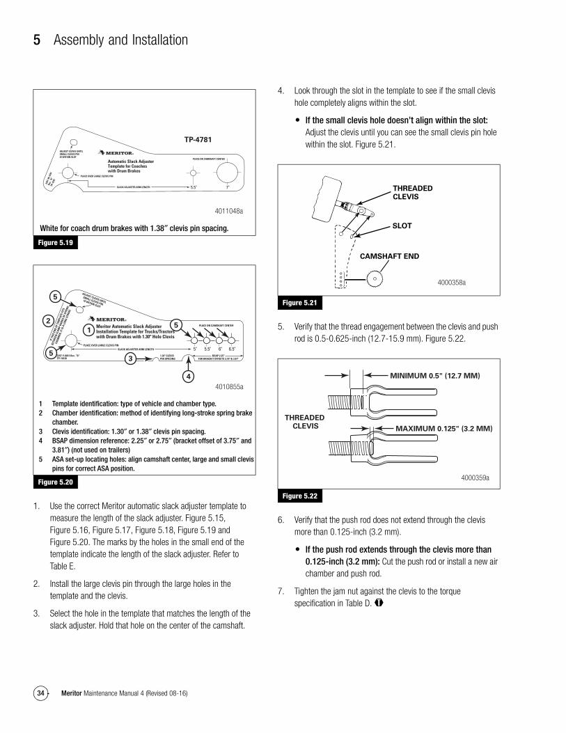
5 Assembly and Installation
34 Meritor Maintenance Manual 4 (Revised 08-16)
Figure 5.19
Figure 5.20
1. Use the correct Meritor automatic slack adjuster template to measure the length of the slack adjuster. Figure 5.15, Figure 5.16, Figure 5.17, Figure 5.18, Figure 5.19 and Figure 5.20. The marks by the holes in the small end of the template indicate the length of the slack adjuster. Refer to Table E.
2. Install the large clevis pin through the large holes in the template and the clevis.
3. Select the hole in the template that matches the length of the slack adjuster. Hold that hole on the center of the camshaft.
4. Look through the slot in the template to see if the small clevis hole completely aligns within the slot.
� If the small clevis hole doesn’t align within the slot: Adjust the clevis until you can see the small clevis pin hole within the slot. Figure 5.21.
Figure 5.21
5. Verify that the thread engagement between the clevis and push rod is 0.5-0.625-inch (12.7-15.9 mm). Figure 5.22.
Figure 5.22
6. Verify that the push rod does not extend through the clevis more than 0.125-inch (3.2 mm).
� If the push rod extends through the clevis more than 0.125-inch (3.2 mm): Cut the push rod or install a new air chamber and push rod.
7. Tighten the jam nut against the clevis to the torque specification in Table D. @
Figure 5.19
White for coach drum brakes with 1.38″ clevis pin spacing.
Figure 5.20
1 Template identification: type of vehicle and chamber type.2 Chamber identification: method of identifying long-stroke spring brake
chamber.3 Clevis identification: 1.30″ or 1.38″ clevis pin spacing.4 BSAP dimension reference: 2.25″ or 2.75″ (bracket offset of 3.75″ and
3.81″) (not used on trailers)5 ASA set-up locating holes: align camshaft center, large and small clevis
pins for correct ASA position.
PLACE ON CAMSHAFT CENTER
ADJUST CLEVIS UNTILSMALL CLEVIS PINIS WITHIN SLOT
PLACE OVER LARGE CLEVIS PIN
SLACK ADJUSTER ARM LENGTH
Automatic Slack AdjusterTemplate for Coaches with Drum Brakes
5.5" 7"
2297
-W-4
781
Rev.
”K“
TP-4
781
4011048a
TP-4781
Meritor Automatic Slack Adjuster Installation Template for Trucks/Tractorswith Drum Brakes with 1.30" Hole Clevis
5" 5.5" 6" 6.5"2297-Y-8813 Rev. ”B“TP-10130
1.30" CLEVISPIN SPACING
BSAP 2.25"FOR BRACKET OFFSETS 3.75" & 3.81"
PLACE ON CAMSHAFT CENTER
ADJUST CLEVIS UNTIL
SMALL CLEVIS PINIS WITHIN SLOT
IF T
HIS
END
OF T
EMPL
ATE
FITS
BETW
EEN
CLA
MP
BAN
DS O
F SP
RIN
G
CHAM
BER,
IT IS
A L
ONG
STRO
KE
PLACE OVER LARGE CLEVIS PINSLACK ADJUSTER ARM LENGTH
4010855a
5
3
4
52
1
5
Figure 5.21
Figure 5.22
THREADEDCLEVIS
SLOT
CAMSHAFT END
4000358a
MINIMUM 0.5" (12.7 MM)
MAXIMUM 0.125" (3.2 MM)
THREADED CLEVIS
4000359a
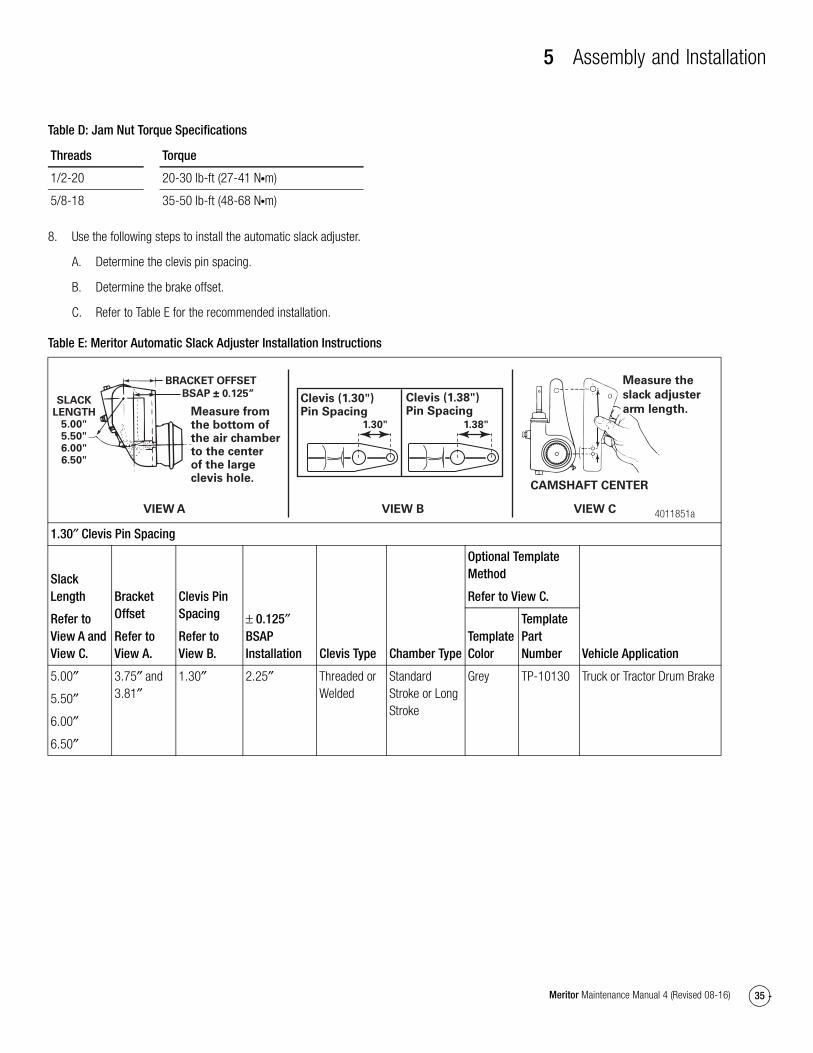
5 Assembly and Installation
35Meritor Maintenance Manual 4 (Revised 08-16)
Table D: Jam Nut Torque Specifications
8. Use the following steps to install the automatic slack adjuster.
A. Determine the clevis pin spacing.
B. Determine the brake offset.
C. Refer to Table E for the recommended installation.
Table E: Meritor Automatic Slack Adjuster Installation Instructions
Threads Torque
1/2-20 20-30 lb-ft (27-41 N�m)
5/8-18 35-50 lb-ft (48-68 N�m)
1.30″ Clevis Pin Spacing
Slack Length
Refer to View A and View C.
Bracket Offset
Refer to View A.
Clevis Pin Spacing
Refer to View B.
± 0.125″ BSAP Installation Clevis Type Chamber Type
Optional Template Method
Refer to View C.
Vehicle ApplicationTemplate Color
Template Part Number
5.00″
5.50″
6.00″
6.50″
3.75″ and 3.81″
1.30″ 2.25″ Threaded or Welded
Standard Stroke or Long Stroke
Grey TP-10130 Truck or Tractor Drum Brake
BRACKET OFFSET
SLACKLENGTH
5.00"5.50"6.00"6.50"
VIEW A
Measure fromthe bottom ofthe air chamberto the centerof the large clevis hole.
BSAP ± 0.125” Clevis (1.38")Pin Spacing
Clevis (1.30")Pin Spacing
1.38"1.30"
VIEW B 4011851a
CAMSHAFT CENTER
VIEW C
Measure the
slack adjuster
arm length.
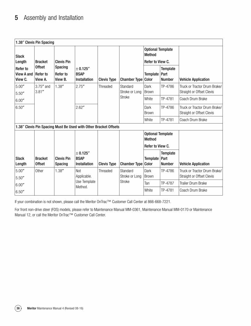
5 Assembly and Installation
36 Meritor Maintenance Manual 4 (Revised 08-16)
If your combination is not shown, please call the Meritor OnTrac™ Customer Call Center at 866-668-7221.
For front non-drive steer (FDS) models, please refer to Maintenance Manual MM-0361, Maintenance Manual MM-0170 or Maintenance Manual 12, or call the Meritor OnTrac™ Customer Call Center.
1.38″ Clevis Pin Spacing
Slack Length
Refer to View A and View C.
Bracket Offset
Refer to View A.
Clevis Pin Spacing
Refer to View B.
± 0.125″ BSAP Installation Clevis Type Chamber Type
Optional Template Method
Refer to View C.
Vehicle ApplicationTemplate Color
Template Part Number
5.00″
5.50″
6.00″
3.75″ and 3.81″
1.38″ 2.75″ Threaded Standard Stroke or Long Stroke
Dark Brown
TP-4786 Truck or Tractor Drum Brake/Straight or Offset Clevis
White TP-4781 Coach Drum Brake
6.50″ 2.62″ Dark Brown
TP-4786 Truck or Tractor Drum Brake/Straight or Offset Clevis
White TP-4781 Coach Drum Brake
1.38″ Clevis Pin Spacing Must Be Used with Other Bracket Offsets
Slack Length
Bracket Offset
Clevis Pin Spacing
± 0.125″ BSAP Installation Clevis Type Chamber Type
Optional Template Method
Refer to View C.
Vehicle ApplicationTemplate Color
Template Part Number
5.00″
5.50″
6.00″
6.50″
Other 1.38″ Not Applicable. Use Template Method.
Threaded Standard Stroke or Long Stroke
Dark Brown
TP-4786 Truck or Tractor Drum Brake/Straight or Offset Clevis
Tan TP-4787 Trailer Drum Brake
White TP-4781 Coach Drum Brake
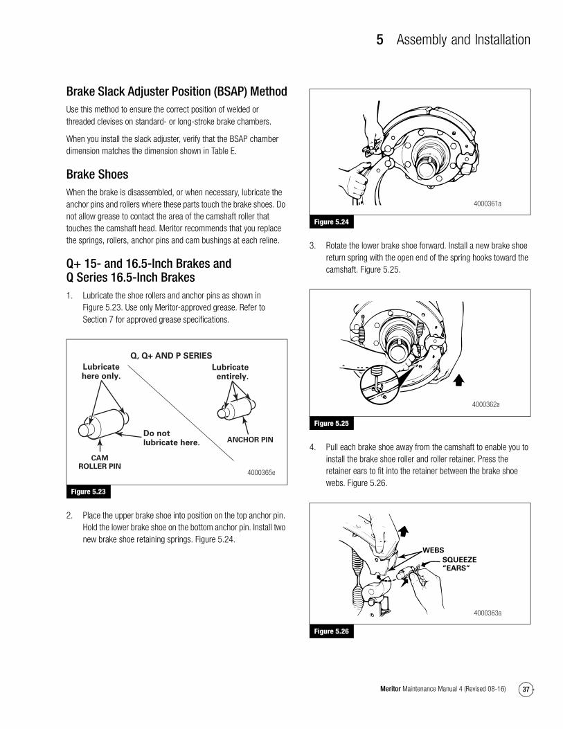
5 Assembly and Installation
37Meritor Maintenance Manual 4 (Revised 08-16)
Brake Slack Adjuster Position (BSAP) MethodUse this method to ensure the correct position of welded or threaded clevises on standard- or long-stroke brake chambers.
When you install the slack adjuster, verify that the BSAP chamber dimension matches the dimension shown in Table E.
Brake ShoesWhen the brake is disassembled, or when necessary, lubricate the anchor pins and rollers where these parts touch the brake shoes. Do not allow grease to contact the area of the camshaft roller that touches the camshaft head. Meritor recommends that you replace the springs, rollers, anchor pins and cam bushings at each reline.
Q+ 15- and 16.5-Inch Brakes and Q Series 16.5-Inch Brakes1. Lubricate the shoe rollers and anchor pins as shown in
Figure 5.23. Use only Meritor-approved grease. Refer to Section 7 for approved grease specifications.
Figure 5.23
2. Place the upper brake shoe into position on the top anchor pin. Hold the lower brake shoe on the bottom anchor pin. Install two new brake shoe retaining springs. Figure 5.24.
Figure 5.24
3. Rotate the lower brake shoe forward. Install a new brake shoe return spring with the open end of the spring hooks toward the camshaft. Figure 5.25.
Figure 5.25
4. Pull each brake shoe away from the camshaft to enable you to install the brake shoe roller and roller retainer. Press the retainer ears to fit into the retainer between the brake shoe webs. Figure 5.26.
Figure 5.26
Figure 5.23
CAMROLLER PIN
Lubricatehere only.
ANCHOR PIN
Lubricateentirely.
Do not lubricate here.
Q, Q+ AND P SERIES
4000365e
Figure 5.24
Figure 5.25
Figure 5.26
4000361a
4000362a
WEBS
SQUEEZE“EARS”
4000363a
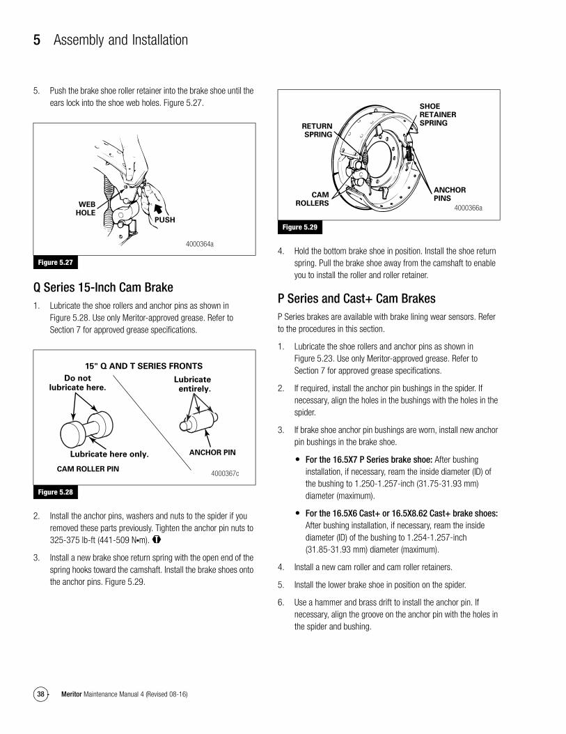
5 Assembly and Installation
38 Meritor Maintenance Manual 4 (Revised 08-16)
5. Push the brake shoe roller retainer into the brake shoe until the ears lock into the shoe web holes. Figure 5.27.
Figure 5.27
Q Series 15-Inch Cam Brake1. Lubricate the shoe rollers and anchor pins as shown in
Figure 5.28. Use only Meritor-approved grease. Refer to Section 7 for approved grease specifications.
Figure 5.28
2. Install the anchor pins, washers and nuts to the spider if you removed these parts previously. Tighten the anchor pin nuts to 325-375 lb-ft (441-509 N�m). @
3. Install a new brake shoe return spring with the open end of the spring hooks toward the camshaft. Install the brake shoes onto the anchor pins. Figure 5.29.
Figure 5.29
4. Hold the bottom brake shoe in position. Install the shoe return spring. Pull the brake shoe away from the camshaft to enable you to install the roller and roller retainer.
P Series and Cast+ Cam BrakesP Series brakes are available with brake lining wear sensors. Refer to the procedures in this section.
1. Lubricate the shoe rollers and anchor pins as shown in Figure 5.23. Use only Meritor-approved grease. Refer to Section 7 for approved grease specifications.
2. If required, install the anchor pin bushings in the spider. If necessary, align the holes in the bushings with the holes in the spider.
3. If brake shoe anchor pin bushings are worn, install new anchor pin bushings in the brake shoe.
� For the 16.5X7 P Series brake shoe: After bushing installation, if necessary, ream the inside diameter (ID) of the bushing to 1.250-1.257-inch (31.75-31.93 mm) diameter (maximum).
� For the 16.5X6 Cast+ or 16.5X8.62 Cast+ brake shoes: After bushing installation, if necessary, ream the inside diameter (ID) of the bushing to 1.254-1.257-inch (31.85-31.93 mm) diameter (maximum).
4. Install a new cam roller and cam roller retainers.
5. Install the lower brake shoe in position on the spider.
6. Use a hammer and brass drift to install the anchor pin. If necessary, align the groove on the anchor pin with the holes in the spider and bushing.
Figure 5.27
Figure 5.28
WEBHOLE
PUSH
4000364a
CAM ROLLER PIN
Lubricate here only.
Do notlubricate here.
15" Q AND T SERIES FRONTS
4000367c
ANCHOR PIN
Lubricateentirely.
Figure 5.29
CAMROLLERS
RETURNSPRING
SHOERETAINERSPRING
ANCHORPINS
4000366a
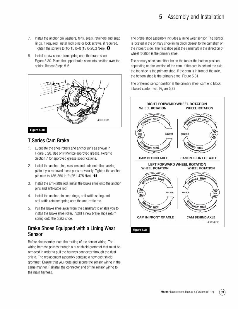
5 Assembly and Installation
39Meritor Maintenance Manual 4 (Revised 08-16)
7. Install the anchor pin washers, felts, seals, retainers and snap rings, if required. Install lock pins or lock screws, if required. Tighten the screws to 10-15 lb-ft (13.6-20.3 N�m). @
8. Install a new shoe return spring onto the brake shoe. Figure 5.30. Place the upper brake shoe into position over the spider. Repeat Steps 5-6.
Figure 5.30
T Series Cam Brake1. Lubricate the shoe rollers and anchor pins as shown in
Figure 5.28. Use only Meritor-approved grease. Refer to Section 7 for approved grease specifications.
2. Install the anchor pins, washers and nuts onto the backing plate if you removed these parts previously. Tighten the anchor pin nuts to 185-350 lb-ft (251-475 N�m). @
3. Install the anti-rattle rod. Install the brake shoe onto the anchor pins and anti-rattle rod.
4. Install the anchor pin snap rings, anti-rattle spring and anti-rattle retainer spring onto the anti-rattle rod.
5. Pull the brake shoe away from the camshaft to enable you to install the brake shoe roller. Install a new brake shoe return spring onto the brake shoe.
Brake Shoes Equipped with a Lining Wear SensorBefore disassembly, note the routing of the sensor wiring. The wiring harness passes through a dust shield grommet that must be removed in order to pull the harness connector through the dust shield. The replacement assembly contains a new dust shield grommet. Ensure that you route and secure the sensor wiring in the same manner. Reinstall the connector end of the sensor wiring to the main harness.
The brake shoe assembly includes a lining wear sensor. The sensor is located in the primary shoe lining block closest to the camshaft on the inboard side. The first shoe past the camshaft in the direction of wheel rotation is the primary shoe.
The primary shoe can either be on the top or the bottom position, depending on the location of the cam. If the cam is behind the axle, the top shoe is the primary shoe. If the cam is in front of the axle, the bottom shoe is the primary shoe. Figure 5.31.
The preferred sensor position is the primary shoe, cam end block, inboard center rivet. Figure 5.32.
Figure 5.31
Figure 5.30
4000368a
Figure 5.31
WHEEL ROTATION WHEEL ROTATION
WHEEL ROTATIONWHEEL ROTATION
CAM BEHIND AXLE
CAM IN FRONT OF AXLECAM BEHIND AXLE
CAM IN FRONT OF AXLE
PRIMARY SHOE
SECONDARY SHOE
CAM
SECONDARY SHOE
PRIMARY SHOE
CAMANCHOR ANCHOR
SECONDARY SHOE
PRIMARY SHOE
PRIMARY SHOE
SECONDARY SHOE
4006499c
ANCHOR ANCHORCAM
LEFT FORWARD WHEEL ROTATION
RIGHT FORWARD WHEEL ROTATION
CAM
CAM
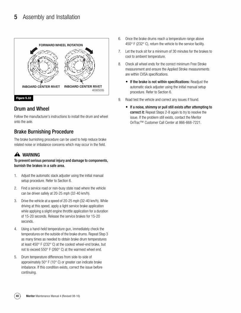
5 Assembly and Installation
40 Meritor Maintenance Manual 4 (Revised 08-16)
Figure 5.32
Drum and WheelFollow the manufacturer’s instructions to install the drum and wheel onto the axle.
Brake Burnishing ProcedureThe brake burnishing procedure can be used to help reduce brake related noise or imbalance concerns which may occur in the field.
WARNINGTo prevent serious personal injury and damage to components, burnish the brakes in a safe area.
1. Adjust the automatic slack adjuster using the initial manual setup procedure. Refer to Section 6.
2. Find a service road or non-busy state road where the vehicle can be driven safely at 20-25 mph (32-40 km/h).
3. Drive the vehicle at a speed of 20-25 mph (32-40 km/h). While driving at this speed, apply a light service brake application while applying a slight engine throttle application for a duration of 15-20 seconds. Release the service brakes for 15-20 seconds.
4. Using a hand-held temperature gun, immediately check the temperatures on the outside of the brake drums. Repeat Step 3 as many times as needed to obtain brake drum temperatures at least 450° F (232° C) at the coolest wheel-end brake, but not to exceed 550° F (260° C) at the warmest wheel end.
5. Drum temperature differences from side-to-side of approximately 50° F (10° C) or greater can indicate brake imbalance. If this condition exists, correct the issue before continuing.
6. Once the brake drums reach a temperature range above 450° F (232° C), return the vehicle to the service facility.
7. Let the truck sit for a minimum of 30 minutes for the brakes to cool to ambient temperature.
8. Check all wheel ends for the correct minimum Free Stroke measurement and ensure the Applied Stroke measurements are within CVSA specifications.
� If the brake is not within specifications: Readjust the automatic slack adjuster using the initial manual setup procedure. Refer to Section 6.
9. Road test the vehicle and correct any issues if found.
� If a noise, shimmy or pull still exists after attempting to correct it: Repeat Steps 2-8 again to try to resolve the issue. If the problem still exists, contact the Meritor OnTrac™ Customer Call Center at 866-668-7221.
Figure 5.32
4006500bINBOARD CENTER RIVET INBOARD CENTER RIVET
FORWARD WHEEL ROTATION
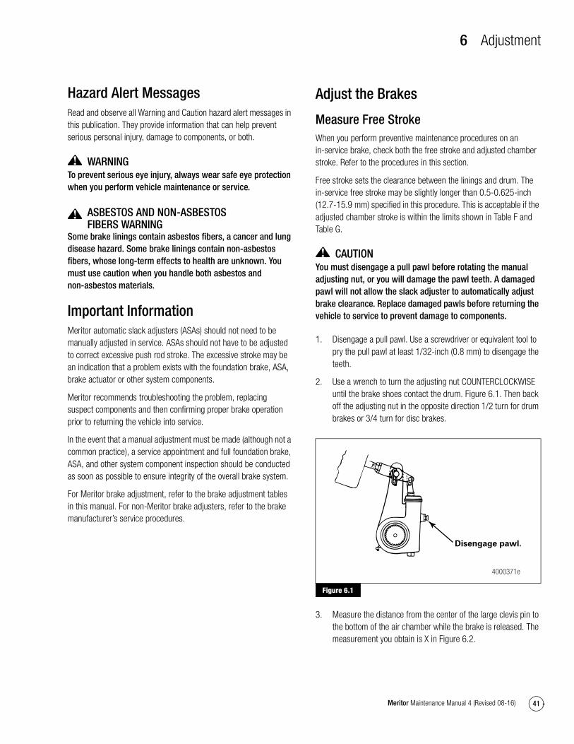
6 Adjustment
41Meritor Maintenance Manual 4 (Revised 08-16)
6 AdjustmentHazard Alert MessagesRead and observe all Warning and Caution hazard alert messages in this publication. They provide information that can help prevent serious personal injury, damage to components, or both.
WARNINGTo prevent serious eye injury, always wear safe eye protection when you perform vehicle maintenance or service.
ASBESTOS AND NON-ASBESTOS FIBERS WARNING
Some brake linings contain asbestos fibers, a cancer and lung disease hazard. Some brake linings contain non-asbestos fibers, whose long-term effects to health are unknown. You must use caution when you handle both asbestos and non-asbestos materials.
Important InformationMeritor automatic slack adjusters (ASAs) should not need to be manually adjusted in service. ASAs should not have to be adjusted to correct excessive push rod stroke. The excessive stroke may be an indication that a problem exists with the foundation brake, ASA, brake actuator or other system components.
Meritor recommends troubleshooting the problem, replacing suspect components and then confirming proper brake operation prior to returning the vehicle into service.
In the event that a manual adjustment must be made (although not a common practice), a service appointment and full foundation brake, ASA, and other system component inspection should be conducted as soon as possible to ensure integrity of the overall brake system.
For Meritor brake adjustment, refer to the brake adjustment tables in this manual. For non-Meritor brake adjusters, refer to the brake manufacturer’s service procedures.
Adjust the Brakes
Measure Free StrokeWhen you perform preventive maintenance procedures on an in-service brake, check both the free stroke and adjusted chamber stroke. Refer to the procedures in this section.
Free stroke sets the clearance between the linings and drum. The in-service free stroke may be slightly longer than 0.5-0.625-inch (12.7-15.9 mm) specified in this procedure. This is acceptable if the adjusted chamber stroke is within the limits shown in Table F and Table G.
CAUTIONYou must disengage a pull pawl before rotating the manual adjusting nut, or you will damage the pawl teeth. A damaged pawl will not allow the slack adjuster to automatically adjust brake clearance. Replace damaged pawls before returning the vehicle to service to prevent damage to components.
1. Disengage a pull pawl. Use a screwdriver or equivalent tool to pry the pull pawl at least 1/32-inch (0.8 mm) to disengage the teeth.
2. Use a wrench to turn the adjusting nut COUNTERCLOCKWISE until the brake shoes contact the drum. Figure 6.1. Then back off the adjusting nut in the opposite direction 1/2 turn for drum brakes or 3/4 turn for disc brakes.
Figure 6.1
3. Measure the distance from the center of the large clevis pin to the bottom of the air chamber while the brake is released. The measurement you obtain is X in Figure 6.2.
Figure 6.1
Disengage pawl.
4000371e
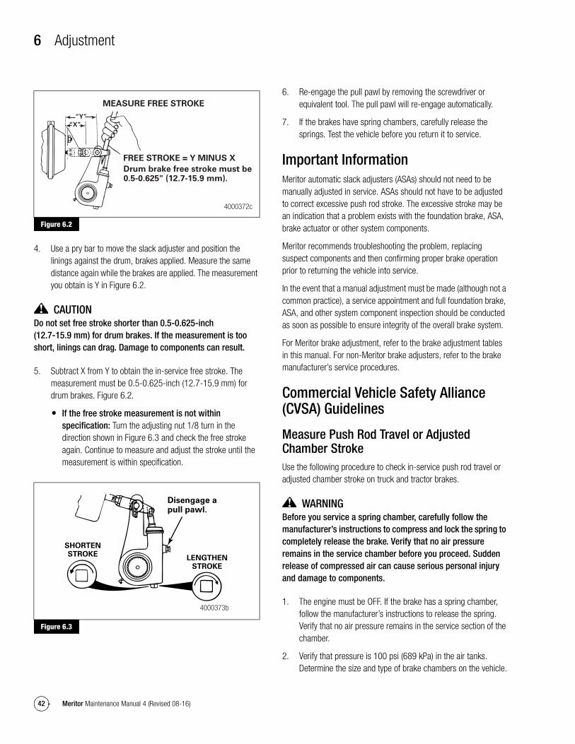
6 Adjustment
42 Meritor Maintenance Manual 4 (Revised 08-16)
Figure 6.2
4. Use a pry bar to move the slack adjuster and position the linings against the drum, brakes applied. Measure the same distance again while the brakes are applied. The measurement you obtain is Y in Figure 6.2.
CAUTIONDo not set free stroke shorter than 0.5-0.625-inch (12.7-15.9 mm) for drum brakes. If the measurement is too short, linings can drag. Damage to components can result.
5. Subtract X from Y to obtain the in-service free stroke. The measurement must be 0.5-0.625-inch (12.7-15.9 mm) for drum brakes. Figure 6.2.
� If the free stroke measurement is not within specification: Turn the adjusting nut 1/8 turn in the direction shown in Figure 6.3 and check the free stroke again. Continue to measure and adjust the stroke until the measurement is within specification.
Figure 6.3
6. Re-engage the pull pawl by removing the screwdriver or equivalent tool. The pull pawl will re-engage automatically.
7. If the brakes have spring chambers, carefully release the springs. Test the vehicle before you return it to service.
Important InformationMeritor automatic slack adjusters (ASAs) should not need to be manually adjusted in service. ASAs should not have to be adjusted to correct excessive push rod stroke. The excessive stroke may be an indication that a problem exists with the foundation brake, ASA, brake actuator or other system components.
Meritor recommends troubleshooting the problem, replacing suspect components and then confirming proper brake operation prior to returning the vehicle into service.
In the event that a manual adjustment must be made (although not a common practice), a service appointment and full foundation brake, ASA, and other system component inspection should be conducted as soon as possible to ensure integrity of the overall brake system.
For Meritor brake adjustment, refer to the brake adjustment tables in this manual. For non-Meritor brake adjusters, refer to the brake manufacturer’s service procedures.
Commercial Vehicle Safety Alliance (CVSA) Guidelines
Measure Push Rod Travel or Adjusted Chamber StrokeUse the following procedure to check in-service push rod travel or adjusted chamber stroke on truck and tractor brakes.
WARNINGBefore you service a spring chamber, carefully follow the manufacturer’s instructions to compress and lock the spring to completely release the brake. Verify that no air pressure remains in the service chamber before you proceed. Sudden release of compressed air can cause serious personal injury and damage to components.
1. The engine must be OFF. If the brake has a spring chamber, follow the manufacturer’s instructions to release the spring. Verify that no air pressure remains in the service section of the chamber.
2. Verify that pressure is 100 psi (689 kPa) in the air tanks. Determine the size and type of brake chambers on the vehicle.
Figure 6.2
Figure 6.3
MEASURE FREE STROKE
“Y”
“X”
FREE STROKE = Y MINUS X
Drum brake free stroke must be 0.5-0.625" (12.7-15.9 mm).
4000372c
SHORTENSTROKE
Disengage a pull pawl.
LENGTHENSTROKE
4000373b
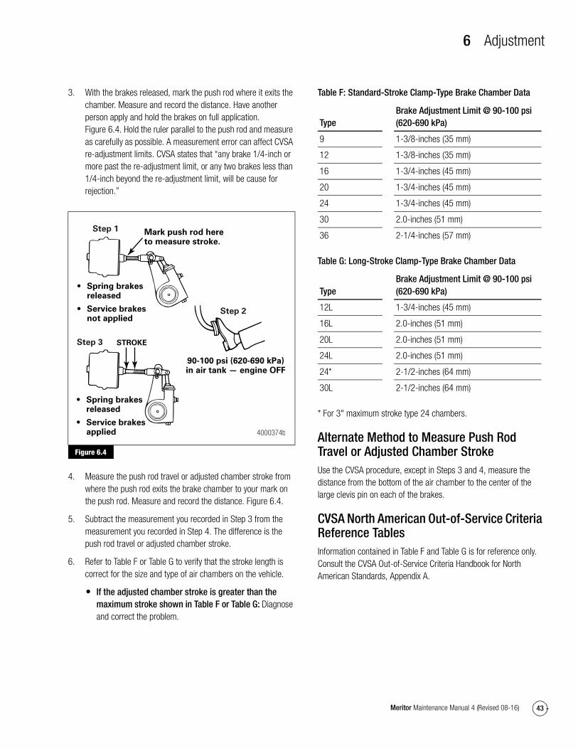
6 Adjustment
43Meritor Maintenance Manual 4 (Revised 08-16)
3. With the brakes released, mark the push rod where it exits the chamber. Measure and record the distance. Have another person apply and hold the brakes on full application. Figure 6.4. Hold the ruler parallel to the push rod and measure as carefully as possible. A measurement error can affect CVSA re-adjustment limits. CVSA states that “any brake 1/4-inch or more past the re-adjustment limit, or any two brakes less than 1/4-inch beyond the re-adjustment limit, will be cause for rejection.”
Figure 6.4
4. Measure the push rod travel or adjusted chamber stroke from where the push rod exits the brake chamber to your mark on the push rod. Measure and record the distance. Figure 6.4.
5. Subtract the measurement you recorded in Step 3 from the measurement you recorded in Step 4. The difference is the push rod travel or adjusted chamber stroke.
6. Refer to Table F or Table G to verify that the stroke length is correct for the size and type of air chambers on the vehicle.
� If the adjusted chamber stroke is greater than the maximum stroke shown in Table F or Table G: Diagnose and correct the problem.
Table F: Standard-Stroke Clamp-Type Brake Chamber Data
Table G: Long-Stroke Clamp-Type Brake Chamber Data
* For 3" maximum stroke type 24 chambers.
Alternate Method to Measure Push Rod Travel or Adjusted Chamber StrokeUse the CVSA procedure, except in Steps 3 and 4, measure the distance from the bottom of the air chamber to the center of the large clevis pin on each of the brakes.
CVSA North American Out-of-Service Criteria Reference TablesInformation contained in Table F and Table G is for reference only. Consult the CVSA Out-of-Service Criteria Handbook for North American Standards, Appendix A.
Figure 6.4
• Spring brakesreleased
• Service brakesnot applied
• Spring brakesreleased
• Service brakesapplied
90-100 psi (620-690 kPa)in air tank — engine OFF
Mark push rod here to measure stroke.
STROKE
4000374b
Step 2
Step 1
Step 3
TypeBrake Adjustment Limit @ 90-100 psi (620-690 kPa)
9 1-3/8-inches (35 mm)
12 1-3/8-inches (35 mm)
16 1-3/4-inches (45 mm)
20 1-3/4-inches (45 mm)
24 1-3/4-inches (45 mm)
30 2.0-inches (51 mm)
36 2-1/4-inches (57 mm)
TypeBrake Adjustment Limit @ 90-100 psi (620-690 kPa)
12L 1-3/4-inches (45 mm)
16L 2.0-inches (51 mm)
20L 2.0-inches (51 mm)
24L 2.0-inches (51 mm)
24* 2-1/2-inches (64 mm)
30L 2-1/2-inches (64 mm)
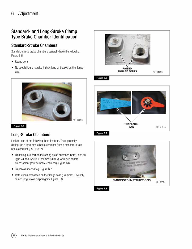
6 Adjustment
44 Meritor Maintenance Manual 4 (Revised 08-16)
Standard- and Long-Stroke Clamp Type Brake Chamber Identification
Standard-Stroke ChambersStandard-stroke brake chambers generally have the following. Figure 6.5.
� Round ports
� No special tag or service instructions embossed on the flange case
Figure 6.5
Long-Stroke ChambersLook for one of the following three features. They generally distinguish a long-stroke brake chamber from a standard-stroke brake chamber (SAE J1817).
� Raised square port on the spring brake chamber (Note: used on Type 24 and Type 30L chambers ONLY), or raised square embossment (service brake chamber). Figure 6.6.
� Trapezoid-shaped tag. Figure 6.7.
� Instructions embossed on the flange case (Example: “Use only 3-inch long stroke diaphragm”). Figure 6.8.
Figure 6.6
Figure 6.7
Figure 6.8
Figure 6.5
4010856a
Figure 6.6
Figure 6.7
Figure 6.8
4010859aRAISED
SQUARE PORTS
4010857aTRAPEZOID
TAG
4010858aEMBOSSED INSTRUCTIONS
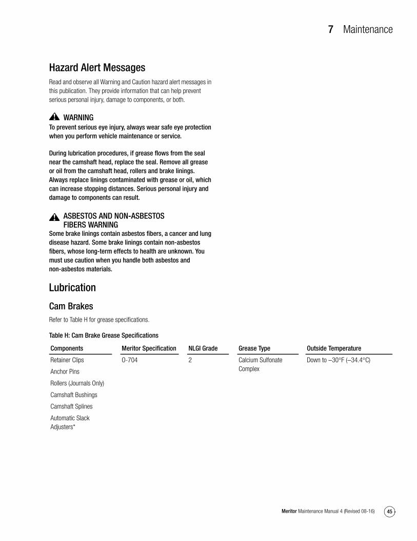
7 Maintenance
45Meritor Maintenance Manual 4 (Revised 08-16)
7 MaintenanceHazard Alert MessagesRead and observe all Warning and Caution hazard alert messages in this publication. They provide information that can help prevent serious personal injury, damage to components, or both.
WARNINGTo prevent serious eye injury, always wear safe eye protection when you perform vehicle maintenance or service.
During lubrication procedures, if grease flows from the seal near the camshaft head, replace the seal. Remove all grease or oil from the camshaft head, rollers and brake linings. Always replace linings contaminated with grease or oil, which can increase stopping distances. Serious personal injury and damage to components can result.
ASBESTOS AND NON-ASBESTOS FIBERS WARNING
Some brake linings contain asbestos fibers, a cancer and lung disease hazard. Some brake linings contain non-asbestos fibers, whose long-term effects to health are unknown. You must use caution when you handle both asbestos and non-asbestos materials.
Lubrication
Cam BrakesRefer to Table H for grease specifications.
Table H: Cam Brake Grease Specifications
Components Meritor Specification NLGI Grade Grease Type Outside Temperature
Retainer Clips
Anchor Pins
Rollers (Journals Only)
Camshaft Bushings
Camshaft Splines
Automatic Slack Adjusters*
O-704 2 Calcium Sulfonate Complex
Down to −30°F (−34.4°C)
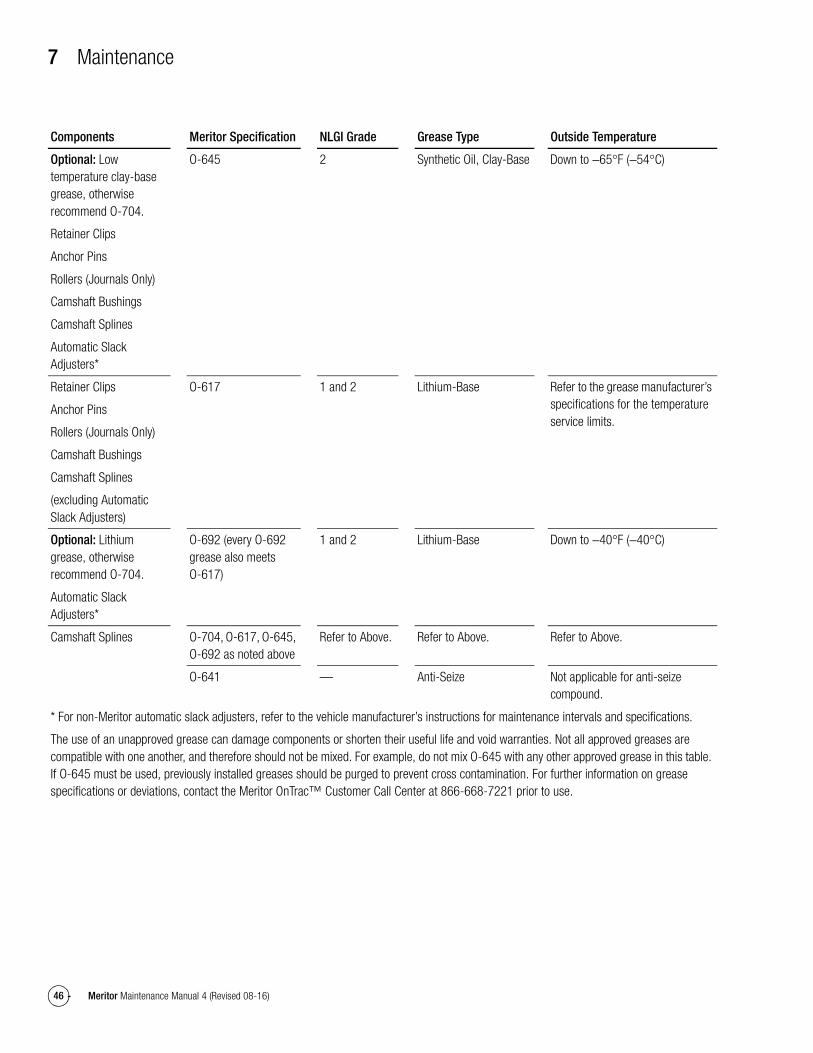
7 Maintenance
46 Meritor Maintenance Manual 4 (Revised 08-16)
Optional: Low temperature clay-base grease, otherwise recommend O-704.
Retainer Clips
Anchor Pins
Rollers (Journals Only)
Camshaft Bushings
Camshaft Splines
Automatic Slack Adjusters*
O-645 2 Synthetic Oil, Clay-Base Down to −65°F (−54°C)
Retainer Clips
Anchor Pins
Rollers (Journals Only)
Camshaft Bushings
Camshaft Splines
(excluding Automatic Slack Adjusters)
O-617 1 and 2 Lithium-Base Refer to the grease manufacturer’s specifications for the temperature service limits.
Optional: Lithium grease, otherwise recommend O-704.
Automatic Slack Adjusters*
O-692 (every O-692 grease also meets O-617)
1 and 2 Lithium-Base Down to −40°F (−40°C)
Camshaft Splines O-704, O-617, O-645, O-692 as noted above
Refer to Above. Refer to Above. Refer to Above.
O-641 — Anti-Seize Not applicable for anti-seize compound.
* For non-Meritor automatic slack adjusters, refer to the vehicle manufacturer’s instructions for maintenance intervals and specifications.
The use of an unapproved grease can damage components or shorten their useful life and void warranties. Not all approved greases are compatible with one another, and therefore should not be mixed. For example, do not mix O-645 with any other approved grease in this table. If O-645 must be used, previously installed greases should be purged to prevent cross contamination. For further information on grease specifications or deviations, contact the Meritor OnTrac™ Customer Call Center at 866-668-7221 prior to use.
Components Meritor Specification NLGI Grade Grease Type Outside Temperature
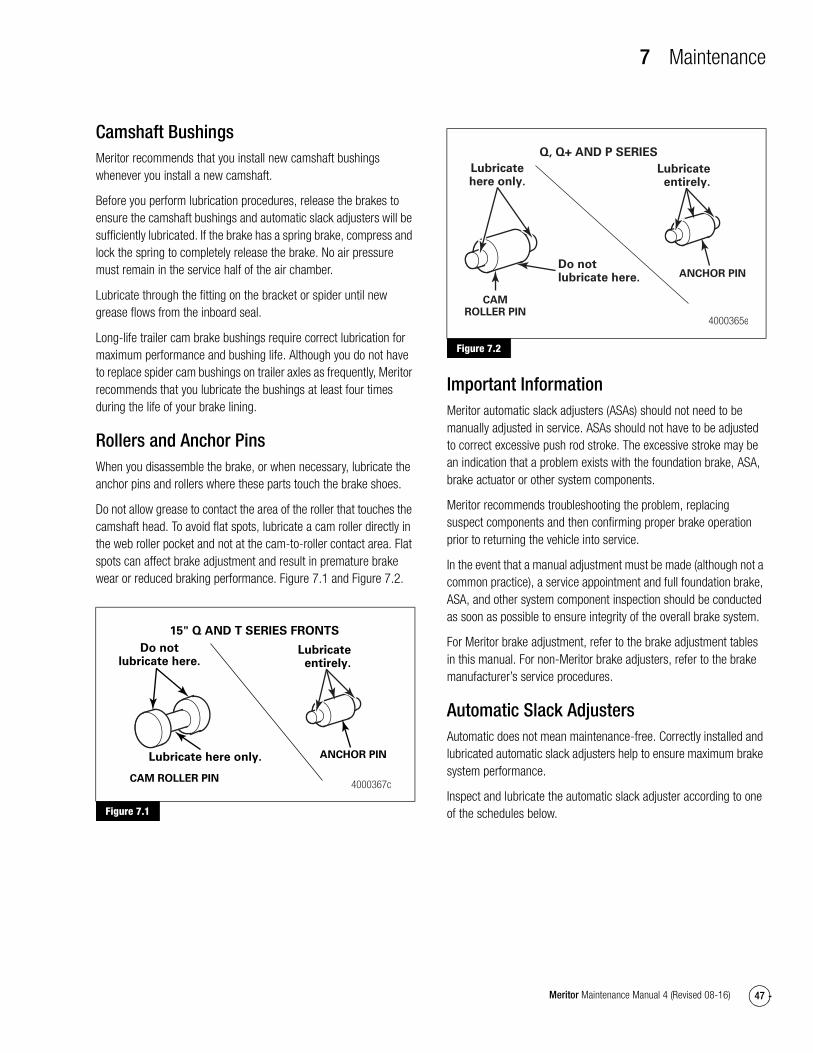
7 Maintenance
47Meritor Maintenance Manual 4 (Revised 08-16)
Camshaft BushingsMeritor recommends that you install new camshaft bushings whenever you install a new camshaft.
Before you perform lubrication procedures, release the brakes to ensure the camshaft bushings and automatic slack adjusters will be sufficiently lubricated. If the brake has a spring brake, compress and lock the spring to completely release the brake. No air pressure must remain in the service half of the air chamber.
Lubricate through the fitting on the bracket or spider until new grease flows from the inboard seal.
Long-life trailer cam brake bushings require correct lubrication for maximum performance and bushing life. Although you do not have to replace spider cam bushings on trailer axles as frequently, Meritor recommends that you lubricate the bushings at least four times during the life of your brake lining.
Rollers and Anchor PinsWhen you disassemble the brake, or when necessary, lubricate the anchor pins and rollers where these parts touch the brake shoes.
Do not allow grease to contact the area of the roller that touches the camshaft head. To avoid flat spots, lubricate a cam roller directly in the web roller pocket and not at the cam-to-roller contact area. Flat spots can affect brake adjustment and result in premature brake wear or reduced braking performance. Figure 7.1 and Figure 7.2.
Figure 7.1
Figure 7.2
Important InformationMeritor automatic slack adjusters (ASAs) should not need to be manually adjusted in service. ASAs should not have to be adjusted to correct excessive push rod stroke. The excessive stroke may be an indication that a problem exists with the foundation brake, ASA, brake actuator or other system components.
Meritor recommends troubleshooting the problem, replacing suspect components and then confirming proper brake operation prior to returning the vehicle into service.
In the event that a manual adjustment must be made (although not a common practice), a service appointment and full foundation brake, ASA, and other system component inspection should be conducted as soon as possible to ensure integrity of the overall brake system.
For Meritor brake adjustment, refer to the brake adjustment tables in this manual. For non-Meritor brake adjusters, refer to the brake manufacturer’s service procedures.
Automatic Slack AdjustersAutomatic does not mean maintenance-free. Correctly installed and lubricated automatic slack adjusters help to ensure maximum brake system performance.
Inspect and lubricate the automatic slack adjuster according to one of the schedules below.
Figure 7.1
CAM ROLLER PIN
Lubricate here only.
Do notlubricate here.
15" Q AND T SERIES FRONTS
4000367c
ANCHOR PIN
Lubricateentirely.
Figure 7.2
CAMROLLER PIN
Lubricatehere only.
ANCHOR PIN
Lubricateentirely.
Do not lubricate here.
Q, Q+ AND P SERIES
4000365e

7 Maintenance
48 Meritor Maintenance Manual 4 (Revised 08-16)
CAUTIONBefore you lubricate Meritor automatic slack adjusters at specified maintenance intervals, or when a fleet lubricates slack adjusters at shorter intervals, follow these procedures to prevent damage to components. Park the vehicle on a level surface, block the wheels to prevent the vehicle from moving, and completely release the spring brakes to prevent the slack adjusters from over-adjusting during lubrication procedures.
Before you perform lubrication procedures, release the brakes to ensure the camshaft bushings and automatic slack adjusters will be sufficiently lubricated. If the brake has a spring brake, compress and lock the spring to completely release the brake. No air pressure must remain in the service half of the air chamber.
Use the schedule that requires the most frequent inspection and lubrication, and whenever you reline the brakes. Refer to Table I and Table J for grease specifications.
� Vehicle manufacturer’s schedule
� Fleet’s schedule
� Every six months
� A minimum of four times during the life of the linings
Adjust the BrakesAdjust the wheel bearings before you adjust the brakes.
Clean, inspect and adjust the brakes each time you remove a hub. Check for correct lining-to-drum clearance, push rod travel and brake balance.
Slack Adjuster Inspection and Lubrication1. Ensure the vehicle is parked on a level surface, the wheels are
blocked and the parking brake is released. The slack adjuster must be installed on the brake assembly and connected to the air chamber with both clevis pins.
2. Check the free stroke and the adjusted chamber stroke.
� If the free stroke is not correct: Refer to Section 8 to correct the stroke before you adjust the chamber stroke.
3. Inspect the boot for cuts or other damage.
� If the boot is cut or damaged: Remove the pawl and inspect the grease.
� If the grease is in good condition: Replace the damaged boot with a new boot.
� If the grease is not in good condition: Replace the slack adjuster assembly.
4. Use a grease gun to lubricate the slack adjuster through the grease fitting until one of following is observed.
� The slack adjuster boot begins to inflate.
� Grease purges from the pull pawl.
� Grease purges from around the camshaft.
Slack Adjusters Manufactured Before 1993Remove and replace the slack adjuster when the following conditions are apparent.
� The grease is dry or contaminated.
� The pawl or actuator is worn.
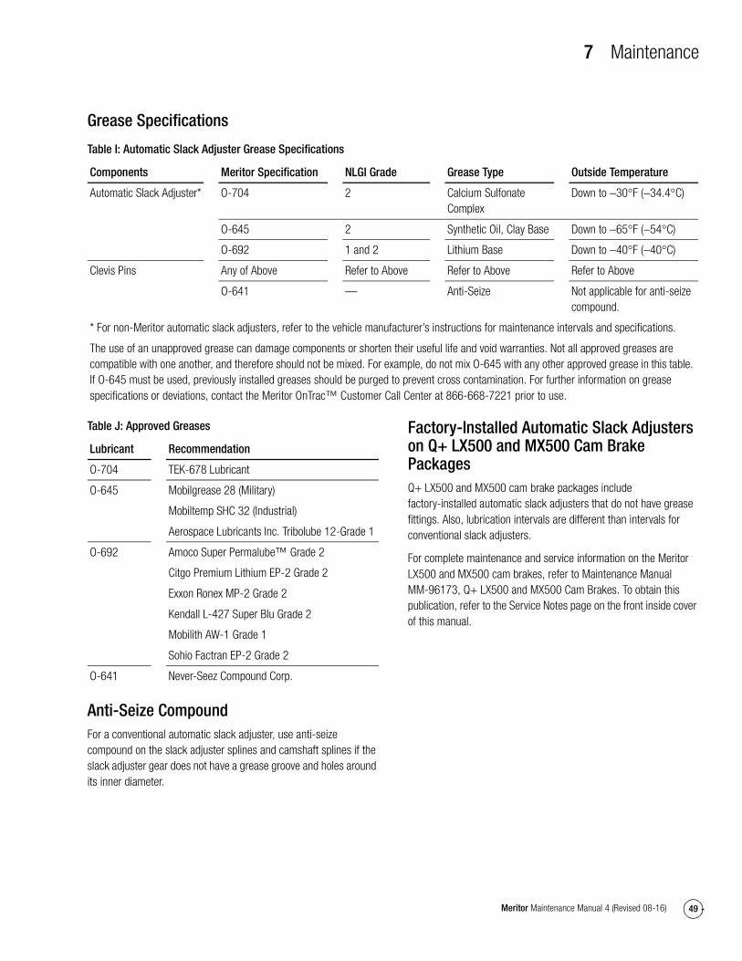
7 Maintenance
49Meritor Maintenance Manual 4 (Revised 08-16)
Grease Specifications
Table I: Automatic Slack Adjuster Grease Specifications
Table J: Approved Greases
Anti-Seize CompoundFor a conventional automatic slack adjuster, use anti-seize compound on the slack adjuster splines and camshaft splines if the slack adjuster gear does not have a grease groove and holes around its inner diameter.
Factory-Installed Automatic Slack Adjusters on Q+ LX500 and MX500 Cam Brake PackagesQ+ LX500 and MX500 cam brake packages include factory-installed automatic slack adjusters that do not have grease fittings. Also, lubrication intervals are different than intervals for conventional slack adjusters.
For complete maintenance and service information on the Meritor LX500 and MX500 cam brakes, refer to Maintenance Manual MM-96173, Q+ LX500 and MX500 Cam Brakes. To obtain this publication, refer to the Service Notes page on the front inside cover of this manual.
Components Meritor Specification NLGI Grade Grease Type Outside Temperature
Automatic Slack Adjuster* O-704 2 Calcium Sulfonate Complex
Down to −30°F (−34.4°C)
O-645 2 Synthetic Oil, Clay Base Down to −65°F (−54°C)
O-692 1 and 2 Lithium Base Down to −40°F (−40°C)
Clevis Pins Any of Above Refer to Above Refer to Above Refer to Above
O-641 — Anti-Seize Not applicable for anti-seize compound.
* For non-Meritor automatic slack adjusters, refer to the vehicle manufacturer’s instructions for maintenance intervals and specifications.
The use of an unapproved grease can damage components or shorten their useful life and void warranties. Not all approved greases are compatible with one another, and therefore should not be mixed. For example, do not mix O-645 with any other approved grease in this table. If O-645 must be used, previously installed greases should be purged to prevent cross contamination. For further information on grease specifications or deviations, contact the Meritor OnTrac™ Customer Call Center at 866-668-7221 prior to use.
Lubricant Recommendation
O-704 TEK-678 Lubricant
O-645 Mobilgrease 28 (Military)
Mobiltemp SHC 32 (Industrial)
Aerospace Lubricants Inc. Tribolube 12-Grade 1
O-692 Amoco Super Permalube™ Grade 2
Citgo Premium Lithium EP-2 Grade 2
Exxon Ronex MP-2 Grade 2
Kendall L-427 Super Blu Grade 2
Mobilith AW-1 Grade 1
Sohio Factran EP-2 Grade 2
O-641 Never-Seez Compound Corp.
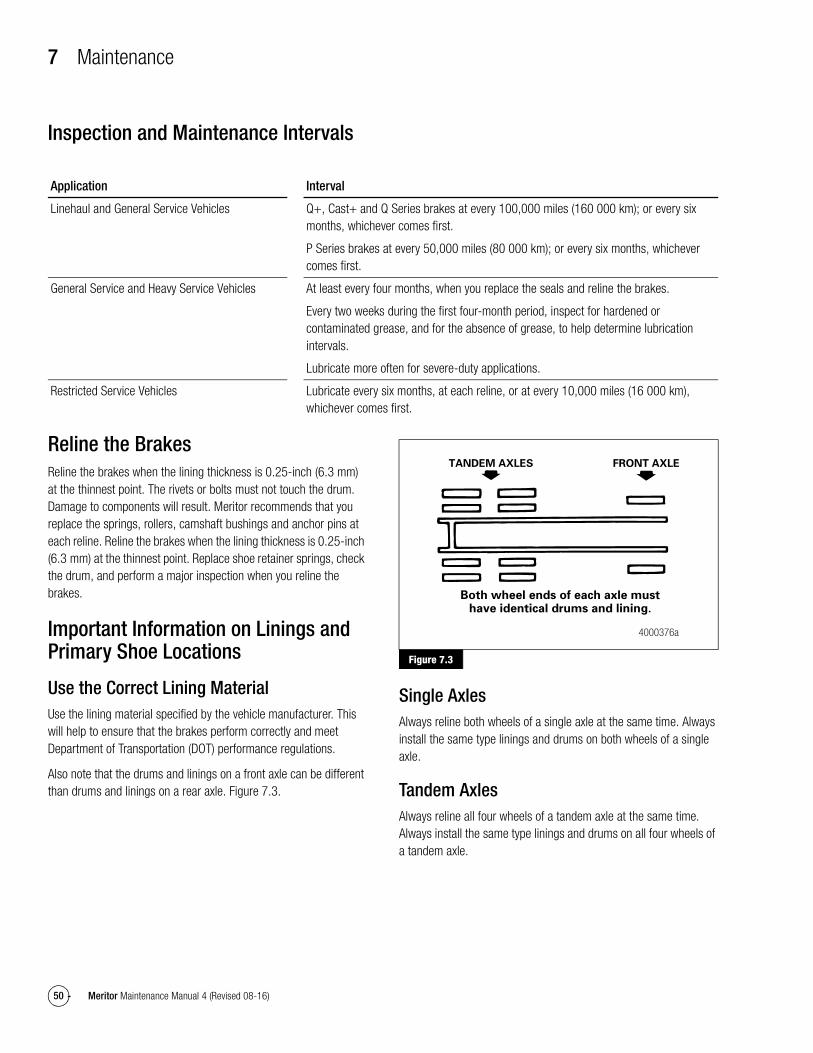
7 Maintenance
50 Meritor Maintenance Manual 4 (Revised 08-16)
Inspection and Maintenance Intervals
Reline the BrakesReline the brakes when the lining thickness is 0.25-inch (6.3 mm) at the thinnest point. The rivets or bolts must not touch the drum. Damage to components will result. Meritor recommends that you replace the springs, rollers, camshaft bushings and anchor pins at each reline. Reline the brakes when the lining thickness is 0.25-inch (6.3 mm) at the thinnest point. Replace shoe retainer springs, check the drum, and perform a major inspection when you reline the brakes.
Important Information on Linings and Primary Shoe Locations
Use the Correct Lining MaterialUse the lining material specified by the vehicle manufacturer. This will help to ensure that the brakes perform correctly and meet Department of Transportation (DOT) performance regulations.
Also note that the drums and linings on a front axle can be different than drums and linings on a rear axle. Figure 7.3.
Figure 7.3
Single AxlesAlways reline both wheels of a single axle at the same time. Always install the same type linings and drums on both wheels of a single axle.
Tandem AxlesAlways reline all four wheels of a tandem axle at the same time. Always install the same type linings and drums on all four wheels of a tandem axle.
Application Interval
Linehaul and General Service Vehicles Q+, Cast+ and Q Series brakes at every 100,000 miles (160 000 km); or every six months, whichever comes first.
P Series brakes at every 50,000 miles (80 000 km); or every six months, whichever comes first.
General Service and Heavy Service Vehicles At least every four months, when you replace the seals and reline the brakes.
Every two weeks during the first four-month period, inspect for hardened or contaminated grease, and for the absence of grease, to help determine lubrication intervals.
Lubricate more often for severe-duty applications.
Restricted Service Vehicles Lubricate every six months, at each reline, or at every 10,000 miles (16 000 km), whichever comes first.
Figure 7.3
TANDEM AXLES FRONT AXLE
Both wheel ends of each axle musthave identical drums and lining.
4000376a
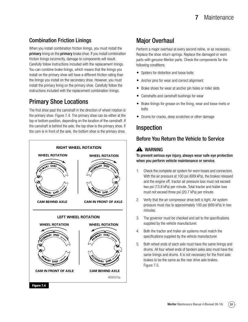
7 Maintenance
51Meritor Maintenance Manual 4 (Revised 08-16)
Combination Friction LiningsWhen you install combination friction linings, you must install the primary lining on the primary brake shoe. If you install combination friction linings incorrectly, damage to components will result. Carefully follow instructions included with the replacement linings. You can combine brake linings, which means that the linings you install on the primary shoe will have a different friction rating than the linings you install on the secondary shoe. However, you must install the primary lining on the primary shoe. Carefully follow the instructions included with the replacement combination linings.
Primary Shoe LocationsThe first shoe past the camshaft in the direction of wheel rotation is the primary shoe. Figure 7.4. The primary shoe can be either at the top or bottom position, depending on the location of the camshaft. If the camshaft is behind the axle, the top shoe is the primary shoe. If the cam is in front of the axle, the bottom shoe is the primary shoe.
Figure 7.4
Major OverhaulPerform a major overhaul at every second reline, or as necessary. Replace the shoe return springs. Replace the damaged or worn parts with genuine Meritor parts. Check the components for the following conditions.
� Spiders for distortion and loose bolts
� Anchor pins for wear and correct alignment
� Brake shoes for wear at anchor pin holes or roller slots
� Camshafts and camshaft bushings for wear
� Brake linings for grease on the lining, wear and loose rivets or bolts
� Drums for cracks, deep scratches or other damage
Inspection
Before You Return the Vehicle to Service
WARNINGTo prevent serious eye injury, always wear safe eye protection when you perform vehicle maintenance or service.
1. Check the complete air system for worn hoses and connectors. With the air pressure at 100 psi (689 kPa), the brakes released and the engine off, tractor air pressure loss must not exceed two psi (13.8 kPa) per minute. Total tractor and trailer loss must not exceed three psi (20.7 kPa) per minute.
2. Verify that the air compressor drive belt is tight. Air system pressure must rise to approximately 100 psi (689 kPa) in two minutes.
3. The governor must be checked and set to the specifications supplied by the vehicle manufacturer.
4. Both the tractor and trailer air systems must match the specifications supplied by the vehicle manufacturer.
5. Both wheel ends of each axle must have the same linings and drums. All four wheel ends of tandem axles also must have the same linings and drums. It is not necessary for the front axle brakes to be the same as the rear drive axle brakes. Figure 7.5.
Figure 7.4
WHEEL ROTATION WHEEL ROTATION
RIGHT WHEEL ROTATION
CAM IN FRONT OF AXLECAM BEHIND AXLE
LEFT WHEEL ROTATION
WHEEL ROTATIONWHEEL ROTATION
CAM BEHIND AXLECAM IN FRONT OF AXLE
4000375a
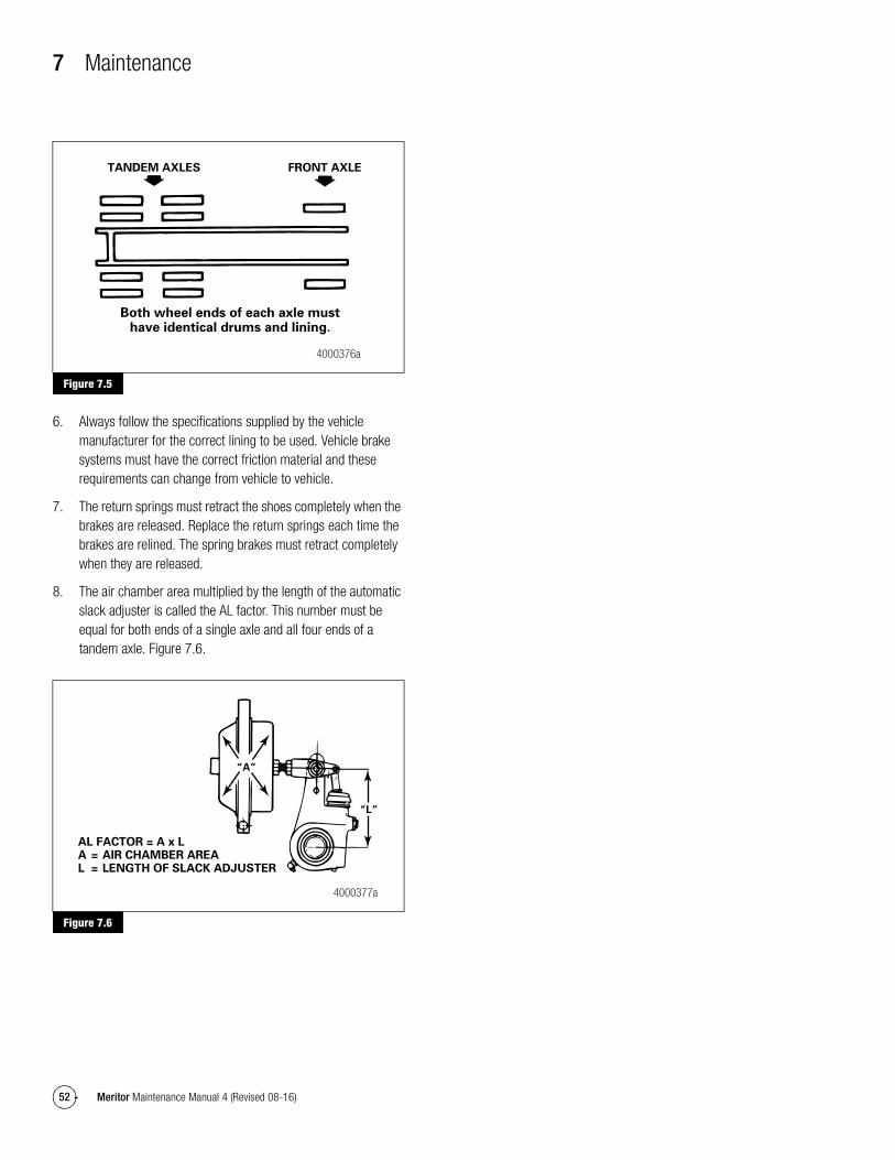
7 Maintenance
52 Meritor Maintenance Manual 4 (Revised 08-16)
Figure 7.5
6. Always follow the specifications supplied by the vehicle manufacturer for the correct lining to be used. Vehicle brake systems must have the correct friction material and these requirements can change from vehicle to vehicle.
7. The return springs must retract the shoes completely when the brakes are released. Replace the return springs each time the brakes are relined. The spring brakes must retract completely when they are released.
8. The air chamber area multiplied by the length of the automatic slack adjuster is called the AL factor. This number must be equal for both ends of a single axle and all four ends of a tandem axle. Figure 7.6.
Figure 7.6
Figure 7.5
Figure 7.6
TANDEM AXLES FRONT AXLE
Both wheel ends of each axle musthave identical drums and lining.
4000376a
AL FACTOR = A x LA = AIR CHAMBER AREAL = LENGTH OF SLACK ADJUSTER
“A”
“L”
4000377a
8 Diagnostics
53Meritor Maintenance Manual 4 (Revised 08-16)
8 DiagnosticsImportant InformationMeritor automatic slack adjusters (ASAs) should not need to be manually adjusted in service. ASAs should not have to be adjusted to correct excessive push rod stroke. The excessive stroke may be an indication that a problem exists with the foundation brake, ASA, brake actuator or other system components.
Meritor recommends troubleshooting the problem, replacing suspect components and then confirming proper brake operation prior to returning the vehicle into service.
In the event that a manual adjustment must be made (although not a common practice), a service appointment and full foundation brake, ASA, and other system component inspection should be conducted as soon as possible to ensure integrity of the overall brake system.
For Meritor brake adjustment, refer to the brake adjustment tables in this manual. For non-Meritor brake adjusters, refer to the brake manufacturer’s service procedures.

8 Diagnostics
54 Meritor Maintenance Manual 4 (Revised 08-16)
Troubleshooting
WARNINGTo prevent serious eye injury, always wear safe eye protection when you perform vehicle maintenance and service.
Table K: Cam Brakes, All Models
Symptoms Possible Causes Corrective Actions
The adjusted stroke is too long.
No adjustment occurs.
The slack adjuster part number is incorrect. Check with the warehouse distributor or original equipment manufacturer.
The clevis is installed at the wrong angle (BSAP or template). Use the correct template or BSAP setting to install the clevis correctly.
Wear between the clevis and collar is excessive, more than 0.060-inch (1.52 mm), (Quick Connect clevis).
Replace with a threaded clevis.
The jam nut at the clevis is loose. Tighten to specification.
The clevis pin bushing in the slack arm is worn. The inside diameter of the bushing is larger than 0.53-inch (13.46 mm).
Replace the bushing.
The return spring in the air chamber is weak or broken. Spring force must be at least 32 lb (142.4 N) at the first push rod movement.
Replace the return spring or air chamber.
The spring brake does not retract fully. Repair or replace the spring brake.
The teeth on the pawl or actuator are worn or stripped. Replace the slack adjuster.
High torque is required to rotate the worm when the slack is removed from the vehicle.
� In service slack, maximum worm torque: 45 lb-in (5.09 N�m)
� New or rebuilt slack, maximum worm torque: 25 lb-in (2.83 N�m)
Replace the slack adjuster.
Looseness between the camshaft splines and automatic slack adjuster gear is excessive.
Replace the powershaft, gear or automatic slack adjuster as needed.
Components, such as the cam bushing, are worn. Replace the components.
The non-original equipment manufacturer replacement linings may have excessive swell or growth.
Use Meritor-approved linings.
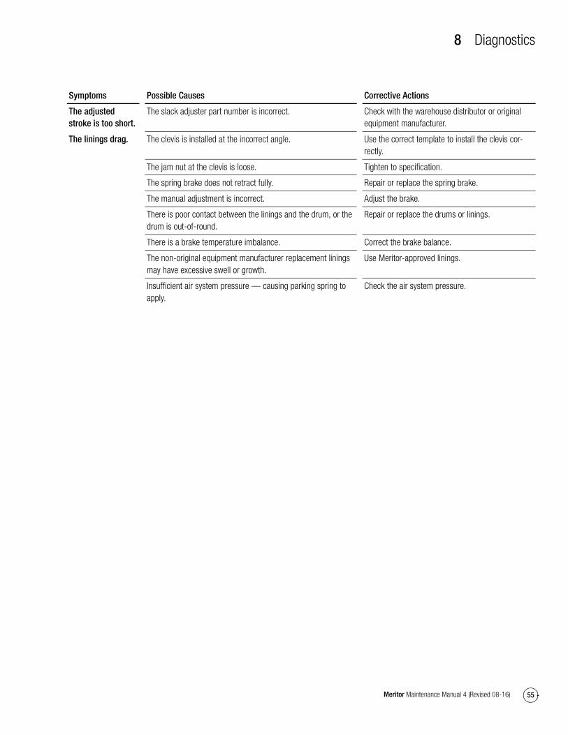
8 Diagnostics
55Meritor Maintenance Manual 4 (Revised 08-16)
The adjusted stroke is too short.
The linings drag.
The slack adjuster part number is incorrect. Check with the warehouse distributor or original equipment manufacturer.
The clevis is installed at the incorrect angle. Use the correct template to install the clevis cor-rectly.
The jam nut at the clevis is loose. Tighten to specification.
The spring brake does not retract fully. Repair or replace the spring brake.
The manual adjustment is incorrect. Adjust the brake.
There is poor contact between the linings and the drum, or the drum is out-of-round.
Repair or replace the drums or linings.
There is a brake temperature imbalance. Correct the brake balance.
The non-original equipment manufacturer replacement linings may have excessive swell or growth.
Use Meritor-approved linings.
Insufficient air system pressure — causing parking spring to apply.
Check the air system pressure.
Symptoms Possible Causes Corrective Actions
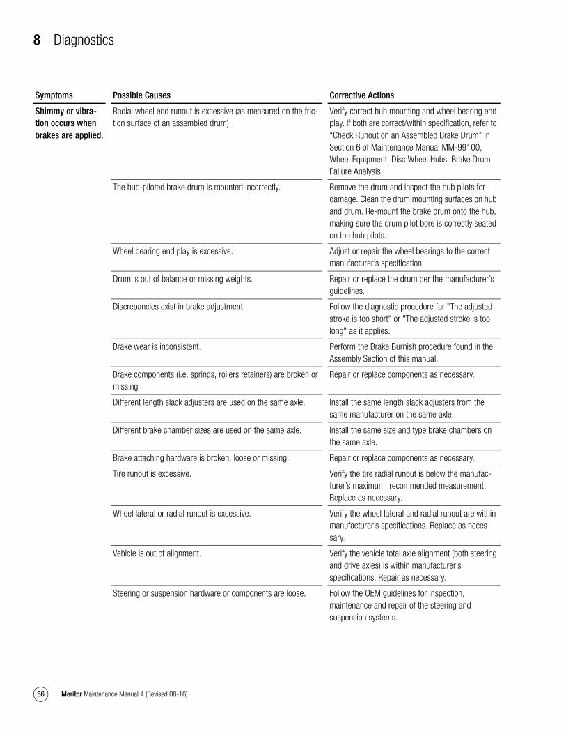
8 Diagnostics
56 Meritor Maintenance Manual 4 (Revised 08-16)
Shimmy or vibra-tion occurs when brakes are applied.
Radial wheel end runout is excessive (as measured on the fric-tion surface of an assembled drum).
Verify correct hub mounting and wheel bearing end play. If both are correct/within specification, refer to “Check Runout on an Assembled Brake Drum” in Section 6 of Maintenance Manual MM-99100, Wheel Equipment, Disc Wheel Hubs, Brake Drum Failure Analysis.
The hub-piloted brake drum is mounted incorrectly. Remove the drum and inspect the hub pilots for damage. Clean the drum mounting surfaces on hub and drum. Re-mount the brake drum onto the hub, making sure the drum pilot bore is correctly seated on the hub pilots.
Wheel bearing end play is excessive. Adjust or repair the wheel bearings to the correct manufacturer’s specification.
Drum is out of balance or missing weights. Repair or replace the drum per the manufacturer’s guidelines.
Discrepancies exist in brake adjustment. Follow the diagnostic procedure for "The adjusted stroke is too short" or "The adjusted stroke is too long" as it applies.
Brake wear is inconsistent. Perform the Brake Burnish procedure found in the Assembly Section of this manual.
Brake components (i.e. springs, rollers retainers) are broken or missing
Repair or replace components as necessary.
Different length slack adjusters are used on the same axle. Install the same length slack adjusters from the same manufacturer on the same axle.
Different brake chamber sizes are used on the same axle. Install the same size and type brake chambers on the same axle.
Brake attaching hardware is broken, loose or missing. Repair or replace components as necessary.
Tire runout is excessive. Verify the tire radial runout is below the manufac-turer’s maximum recommended measurement. Replace as necessary.
Wheel lateral or radial runout is excessive. Verify the wheel lateral and radial runout are within manufacturer’s specifications. Replace as neces-sary.
Vehicle is out of alignment. Verify the vehicle total axle alignment (both steering and drive axles) is within manufacturer’s specifications. Repair as necessary.
Steering or suspension hardware or components are loose. Follow the OEM guidelines for inspection, maintenance and repair of the steering and suspension systems.
Symptoms Possible Causes Corrective Actions
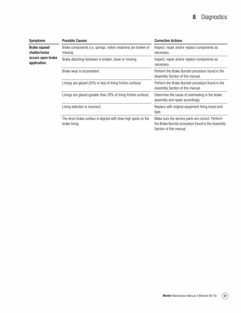
8 Diagnostics
57Meritor Maintenance Manual 4 (Revised 08-16)
Brake squeal/chatter/noise occurs upon brake application.
Brake components (i.e. springs, rollers retainers) are broken or missing.
Inspect, repair and/or replace components as necessary.
Brake attaching hardware is broken, loose or missing. Inspect, repair and/or replace components as necessary.
Brake wear is inconsistent. Perform the Brake Burnish procedure found in the Assembly Section of this manual.
Linings are glazed (20% or less of lining friction surface). Perform the Brake Burnish procedure found in the Assembly Section of this manual.
Linings are glazed (greater than 20% of lining friction surface). Determine the cause of overheating in the brake assembly and repair accordingly.
Lining selection is incorrect. Replace with original equipment lining brand and type.
The drum brake surface is aligned with shoe high spots on the brake lining.
Make sure the service parts are correct. Perform the Brake Burnish procedure found in the Assembly Section of this manual.
Symptoms Possible Causes Corrective Actions
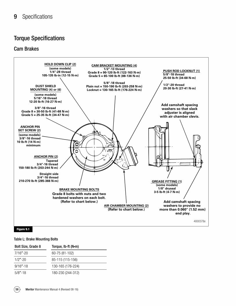
9 Specifications
58 Meritor Maintenance Manual 4 (Revised 08-16)
9 SpecificationsTorque Specifications
Cam Brakes
Figure 9.1
Table L: Brake Mounting Bolts
Figure 9.1
PUSH ROD LOCKNUT (1)5/8"-18 thread25-50 lb-ft (34-68 N·m)
1/2"-20 thread20-30 lb-ft (27-41 N·m)
Add camshaft spacing washers to provide no
more than 0.060" (1.52 mm) end play.
CAM BRACKET MOUNTING (4)1/2"-13 thread
Grade 8 = 90-120 lb-ft (122-163 N·m)Grade 5 = 65-100 lb-ft (88-136 N·m)
5/8"-18 threadPlain nut = 150-190 lb-ft (203-258 N·m)Locknut = 130-165 lb-ft (176-224 N·m)
AIR CHAMBER MOUNTING (2)
(Refer to chart below.)
Add camshaft spacingwashers so that slack
adjuster is alignedwith air chamber clevis.
GREASE FITTING (1)(some models)
1/8" dryseal3-5 lb-ft (4-7 N·m)
BRAKE MOUNTING BOLTS
Grade 8 bolts with nuts and twohardened washers on each bolt.
(Refer to chart below.)
HOLD DOWN CLIP (2)
(some models)1/4"-28 thread
105-135 lb-in (12-15 N·m)
DUST SHIELDMOUNTING (4) or (6)
(some models)5/16"-18 thread
12-20 lb-ft (16-27 N·m)
3/8"-16 threadGrade 8 = 30-50 lb-ft (41-68 N·m)Grade 5 = 25-35 lb-ft (34-47 N·m)
ANCHOR PIN SET SCREW (2)
(some models)3/8"-16 thread
10 lb-ft (14 N·m)minimum
ANCHOR PIN (2)
Tapered3/4"-16 thread
150-180 lb-ft (203-244 N·m)
Straight side3/4"-16 thread
210-270 lb-ft (285-366 N·m)
4000378e
Bolt Size, Grade 8 Torque, lb-ft (N�m)
7/16″-20 60-75 (81-102)
1/2″-20 85-115 (115-156)
9/16″-18 130-165 (176-224)
5/8″-18 180-230 (244-312)
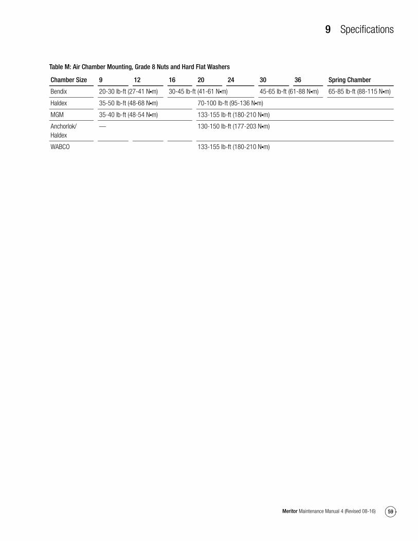
9 Specifications
59Meritor Maintenance Manual 4 (Revised 08-16)
Table M: Air Chamber Mounting, Grade 8 Nuts and Hard Flat Washers
Chamber Size 9 12 16 20 24 30 36 Spring Chamber
Bendix 20-30 lb-ft (27-41 N�m) 30-45 lb-ft (41-61 N�m) 45-65 lb-ft (61-88 N�m) 65-85 lb-ft (88-115 N�m)
Haldex 35-50 lb-ft (48-68 N�m) 70-100 lb-ft (95-136 N�m)
MGM 35-40 lb-ft (48-54 N�m) 133-155 lb-ft (180-210 N�m)
Anchorlok/Haldex
— 130-150 lb-ft (177-203 N�m)
WABCO 133-155 lb-ft (180-210 N�m)

Meritor Heavy Vehicle Systems, LLC2135 West Maple Road Printed in USATroy, MI 48084 USA866-OnTrac1 (668-7221) Copyright 2016 Revised 08-16meritor.com Meritor, Inc. Maintenance Manual 4 (16579)