Embed Size (px)
Citation preview

Application Note
WEBSITE: www.jdsu.com/test
CO
ONT 1
Coaxial cable
Final customer 1
ONT 1ONT 1ONT 1
Coaxial cable
Final customer 1
ONT 2
Final customer 2
Coaxial cable
ONT 2ONT 2ONT 2
Final customer 2
Coaxial cable
ONT 3
Coaxial cable
Final customer 3
ONT 3ONT 3ONT 3
Coaxial cable
Final customer 3
Splitter
OLT
ONT or ONU
OLT
ONT or ONU
ONT 1
Coaxial cable
Final customer 1
ONT 1ONT 1ONT 1
Coaxial cable
Final customer 1
ONT 2
Final customer 2
Coaxial cable
ONT 2ONT 2ONT 2
Final customer 2
Coaxial cable
ONT 3
Coaxial cable
Final customer 3
ONT 3ONT 3ONT 3
Coaxial cable
Final customer 3
Splitter
CO
Maintenance & Troubleshooting of a PON Network with an OTDR
Point-to-Point FTTx NetworkWhen a failure occurs on a point-to-point FTTx network, the network completely shuts down. It is then easy to disconnect the fiber without further affecting the customer issue.
To troubleshoot and fix FTTx network problems, an optical time domain reflectometry (OTDR) test can be performed with any test wavelength, such as 1310 or 1550 nm as the transmission signals are shut down.
ONT 1
Coaxial cable
Final customer 1
ONT 1ONT 1ONT 1
Coaxial cable
Final customer 1
Switch or OLT
ONT or DSLAMCO
Figure 1. FTTx Case = Point-to-Point FTTH Network
Figure 2. Simple PON Network Topology Figure 3. Cascaded PON Topology
Point-to-Multipoint FTTH Network (PON) TopologyTroubleshooting a point-to-multipoint fiber-to-the-home (FTTH) network (also defined as a PON net-work) differs significantly.
The International Telecommunications Union (ITU-T) and Institute of Electrical and Electronic Engineers (IEEE) have created several standards for optical access systems based on PON architecture (G.982, G.983 or G.984 for ITU and 802.3ah or 802.3av for IEEE). As Figure 2 shows, a PON network consists of one optical line terminal (OLT) connected via a splitter to multiple optical network terminals (ONTs) (one for each subscriber, up to 64 subscribers). Sometimes, a second splitter can be connected in cascade to the first splitter (as Figure 3 shows) to dispatch services to buildings or residential areas.
Troubleshooting a faulty passive optical point-to-multipoint network (PON) can be more complex than a point-to-point network. This application note looks at the use of non-intrusive or active fiber testing for troubleshooting PON networks.

Application Note: Maintenance & Troubleshooting of a PON Network with an OTDR 2
Using the network monitoring system at the Network Operation Center (NOC), operators can easily determine which subscribers are affected. They can also identify possible fault elements such as how many customers are affected and whether the PON is cascaded.
The cases below describe each possible scenario:
PON Case 1: Simple PON - Only One Customer is AffectedWhen only one subscriber cannot receive service, three potential faults are probable, see Figure 4: ‒ Fault in the distribution fiber between the customer and the closest splitter ‒ Fault in the ONT equipment ‒ Fault in the customer’s home wiring
Figure 4. PON Case 1—Possible Faults When Only One Subscriber is Affected
PON Case 2: Cascaded PON and all Affected Customers are Connected to the Same SplitterWhen all customers connected to the same splitter cannot receive service, but others connected to the same OLT can, the cause may be because of one of the following (see Figure 5): ‒ Fault at the last splitter ‒ Fault in the fiber link between the cascaded splitters
Figure 5. PON Case 2—Cascaded PON with Affected Subscribers Connected to Last Splitter
ONT 1
Coaxial cable
Final customer 1
ONT 1ONT 1ONT 1
Coaxial cable
Final customer 1
ONT 2
Final customer 2
Coaxial cable
ONT 2ONT 2ONT 2
Final customer 2
Coaxial cable
ONT 3
Coaxial cable
Final customer 3
ONT 3ONT 3ONT 3
Coaxial cable
Final customer 3
Case 1.A - Simple PON - Only one customer affected
Splitter
12
3
OLT
ONT or ONU
ONT 1
Coaxial cable
Final customer 1
ONT 1ONT 1ONT 1
Coaxial cable
Final customer 1
ONT 2
Final customer 2
Coaxial cable
ONT 2ONT 2ONT 2
Final customer 2
Coaxial cable
ONT 3
Coaxial cable
Final customer 3
ONT 3ONT 3ONT 3
Coaxial cable
Final customer 3
First splitter
Last splitter
1 23
OLT
ONT or ONU
ONT 1
Coaxial cable
Final customer 1
ONT 1ONT 1ONT 1
Coaxial cable
Final customer 1
ONT 2
Final customer 2
Coaxial cable
ONT 2ONT 2ONT 2
Final customer 2
Coaxial cable
ONT 3
Coaxial cable
Final customer 3
ONT 3ONT 3ONT 3
Coaxial cable
Final customer 3
First splitter
Case 2 Cascaded PON
Last splitter
12
OLT
ONT or ONU
Application Note: Maintenance & Troubleshooting of a PON Network with an OTDR 3
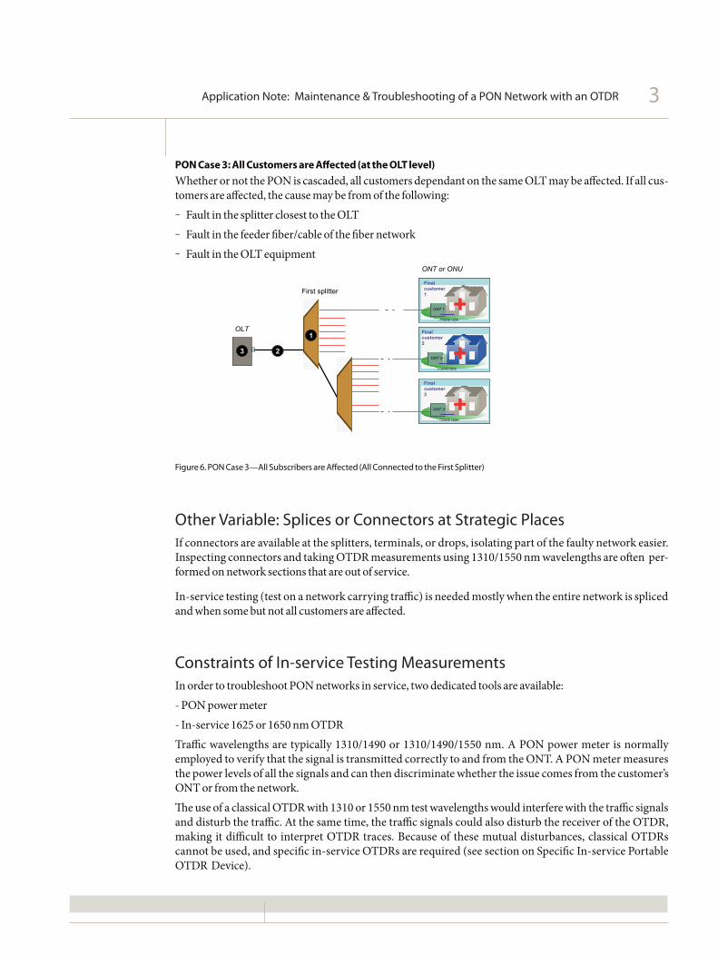
PON Case 3: All Customers are Affected (at the OLT level)Whether or not the PON is cascaded, all customers dependant on the same OLT may be affected. If all cus-tomers are affected, the cause may be from of the following: ‒ Fault in the splitter closest to the OLT ‒ Fault in the feeder fiber/cable of the fiber network ‒ Fault in the OLT equipment
Figure 6. PON Case 3—All Subscribers are Affected (All Connected to the First Splitter)
Other Variable: Splices or Connectors at Strategic PlacesIf connectors are available at the splitters, terminals, or drops, isolating part of the faulty network easier. Inspecting connectors and taking OTDR measurements using 1310/1550 nm wavelengths are often per-formed on network sections that are out of service.
In-service testing (test on a network carrying traffic) is needed mostly when the entire network is spliced and when some but not all customers are affected.
Constraints of In-service Testing MeasurementsIn order to troubleshoot PON networks in service, two dedicated tools are available:- PON power meter- In-service 1625 or 1650 nm OTDRTraffic wavelengths are typically 1310/1490 or 1310/1490/1550 nm. A PON power meter is normally employed to verify that the signal is transmitted correctly to and from the ONT. A PON meter measures the power levels of all the signals and can then discriminate whether the issue comes from the customer’s ONT or from the network.The use of a classical OTDR with 1310 or 1550 nm test wavelengths would interfere with the traffic signals and disturb the traffic. At the same time, the traffic signals could also disturb the receiver of the OTDR, making it difficult to interpret OTDR traces. Because of these mutual disturbances, classical OTDRs cannot be used, and specific in-service OTDRs are required (see section on Specific In-service Portable OTDR Device).
ONT 1
Coaxial cable
Final customer 1
ONT 1ONT 1ONT 1
Coaxial cable
Final customer 1
ONT 2
Final customer 2
Coaxial cable
ONT 2ONT 2ONT 2
Final customer 2
Coaxial cable
ONT 3
Coaxial cable
Final customer 3
ONT 3ONT 3ONT 3
Coaxial cable
Final customer 3
First splitter
1
23
OLT
ONT or ONU

Application Note: Maintenance & Troubleshooting of a PON Network with an OTDR 4
Recommended Steps for Locating FaultsDespite the fact companies with diverse fiber networks have their own methods and procedures, most of them optimize their fault location process to reduce the number of truck rolls.
The schematic in Figure 7 offers a complete view of: ‒ All of the possible fault locations, depending on how many customers are affected ‒ The best location to shoot an OTDR while minimizing truck rolls ‒ Whether or not a specific in-service OTDR device should be used
Figure 7. Schematic Summary
- The OLT- The distribution �ber- The ONT- The customer home wiring
PON Network(Multi-Point FTTH network
- The distribution fiberbetween the customer & theclosest splitter
- The ONT- The customer home wiring
See Figure 4
More than one
Shoot an OTDRfrom the last
splitter towardsthe ONT
In servicemeasurement
Yes
Shoot an OTDRfrom the ONT up
to the closestsplitter
No
Possible faulty elements
Shoot an OTDRfrom the OLT
towards the ONT
- The last splitter- The fiber link between thecascaded splitters
See Figure 5
Are connectorsavailabe at the last
splitter?
No
Shoot an OTDRfrom the last
splitter towardsthe fist splitter
Yes
- The OLT itself- The feeder part of the fibernetwork- The first splitter
See Figure 6
What type ofFFTx Network is
it?
How manycustomers are
affected?
Are affectedcustomers
connected tothe same first
splitter? Shoot an OTDRfrom the OLT
towards the firstsplitter
Which scenario? Second step analysis
Shoot an OTDRfrom the ONTtowards the
closest splitter
One only (whether cascaded splitter or not)
PONCase 1
PONCase 2
No => cascaded splitter
Yes (wether cascaded splitters or not)
PONCase 3
Test 1
Test 2
Test 3
Test 4
Test 5
Test 6
Out of service measurement
Point to Point FTTx Network
CaseFTTx
Are connectorsavailabe at the lastsplitter? (Assumingproblem could not be
solved by phone)

Application Note: Maintenance & Troubleshooting of a PON Network with an OTDR 5
Specific In-service Portable OTDR DeviceThe in-service OTDR was designed specifically for testing live fiber networks. This dedicated device uses an out-of band wavelength (test wavelength far away from traffic wavelength) to enable OTDR testing without disturbing either the network transmitters or the receivers.
JDSU first developed this particular OTDR a few years ago, allowing dark fiber providers to perform in-service monitoring on metropolitan and long-distance networks. In this case, a wavelength dense mul-tiplexer (WDM) is required to connect the OTDR to the network itself while the traffic remains active.
In the case of a PON network, this WDM is no longer needed, except for monitoring purposes (using a remote fiber test system). The PON network is a point-to-multipoint configuration and the troubleshoot-ing test is performed directly from an accessible element (ONT or splitter). The operator can disconnect the element because service is already off downstream toward the customer.
First, the in-service OTDR must not disturb the other customers while shooting the OTDR test wave-length upstream toward the OLT, which is most likely the case, as OLTs reject signals above 1625 nm, based on ITU-T recommendations.
Second, the traffic signals that the OTDR receives will be rejected to obtain accurate OTDR traces. The specific long-pass filter used to protect the OTDR diode can be added either via a jumper between the OTDR and the network or built into the OTDR.
Most equipment providers enable the use of the 1625 nm wavelength for safe testing. Some countries, such as Japan, are nevertheless pushing the 1650 nm wavelength as reflected in the ITU-T L.41 recommen-dation, which provides maintenance wavelengths on fiber-carrying signals. The 1650 nm wavelength is preferred based on the design of the filters and also because it is further away from the traffic signals (cur-rent and future PON technologies).
Figure 8. OTDR Insertion for In-service Monitoring Figure 9. OTDR Insertion for FTTH Troubleshooting at a Customer Location (ONT is disconnected)
Tx
OTDR
WDM
Link #1
SPFilter
LP Filter
Multiplexer
OTDR Filter
ONT 2
Final customer 2
Coaxial cable
OLT
OTDR with built-in LP filter
ONT disconneted
Signals
……………….. Live traffic ………………………………………
ONT 3
Coaxial cable
Final customer 2
ONT 3ONT 3ONT 3
Coaxial cable
Final customer 2
……………….. Live traffic ……………………
………………..NO TRAFFIC ……………………
Test wavelength

Application Note: Maintenance & Troubleshooting of a PON Network with an OTDR 6
Making the Right Testing DecisionsTo optimize maintenance costs and time, it is essential to select the right OTDR tool, the correct pulse width, and the best location to start troubleshooting. OTDR configuration should be set according to the equipment being qualified and the distance to cover.
Consider each case from the scenarios presented in Figure 7. To avoid complexity, this document only analyzes the cases where connectors are only available at the ONT/OLTs.
Case 1: Troubleshooting of the Distribution FiberSimple PON—Only one subscriber affected.Consider that no connectors are available at the splitter (see Figure 7, Test 3)
Case Test OTDR What Must Comment Pulse Width Specific OTDR Location Direction be Seen to Use
Case 1 Customer’s Upstream Distribution Testing through Short pulse In-service OTDROne Home fiber up to the splitter 3 to 30 nscustomer Disconnect the closest splitter is not required,down the ONT as the issue is only on the
distribution fiber side.
Figure 10. OTDR is Shot Upstream and Trace only Matters up to the Splitter
Test the distribution Fiber from Customer 2up to the closest splitter
No need to test beyondthe splitter
The OTDR trace must clearlyshow all events until the closest splitter
Test direction (upstream)

Application Note: Maintenance & Troubleshooting of a PON Network with an OTDR 7
Test the distribution Fiber from Customer 2up to the very first splitter
Last splitter First splitter
Test direction (upstream)
Need to test beyond the closest splitter up to the first splitter
Case 2: Troubleshooting of the Distribution Fiber and the Fiber between the Two Splitters in case of a Cascaded NetworkA cascaded network with 1x4 or 1x8 splitters is often found in Europe.Information received at the network operations center (NOC) says that all customers linked to the second splitter are down. Let’s consider the case where no connectors are available at the splitter (see Figure 7, Test 5).
Case Test OTDR What Must Comment Pulse Width Specific OTDR Location Direction be Seen to Use
Case 2 Customer’s Upstream Distribution fiber Testing through Medium pulse In-service OTDRAll customers home and fiber between the closest splitter 100 to 300 ns - Short dead zoneare down Disconnect the two splitters is requiredafter the the ONTsecond splitter
This case requires viewing the signal after the splitter. The OTDR used must be optimized for this applica-tion and have the shortest possible dead zone as the splitter typically provides 7 to 10 dB loss.
Figure 11. OTDR is Shot Upstream and Trace should Display the Traffic through the Last Splitter up to the First One
Application Note: Maintenance & Troubleshooting of a PON Network with an OTDR 8
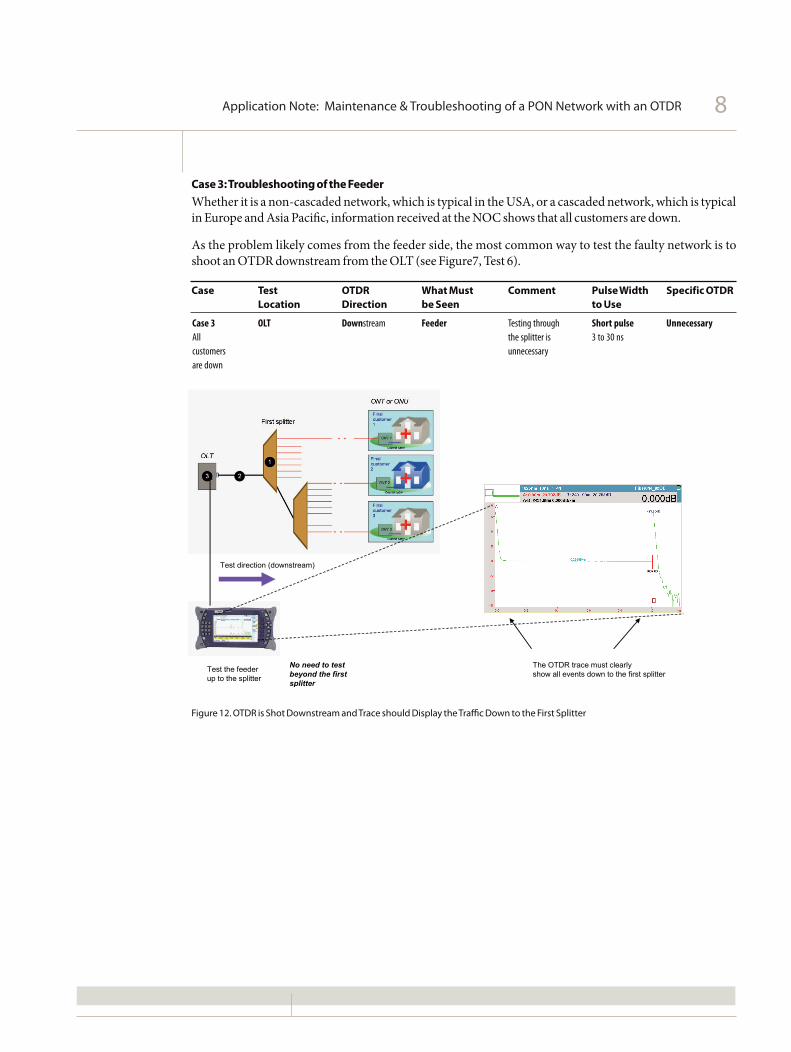
Case 3: Troubleshooting of the FeederWhether it is a non-cascaded network, which is typical in the USA, or a cascaded network, which is typical in Europe and Asia Pacific, information received at the NOC shows that all customers are down.
As the problem likely comes from the feeder side, the most common way to test the faulty network is to shoot an OTDR downstream from the OLT (see Figure7, Test 6).
Case Test OTDR What Must Comment Pulse Width Specific OTDR Location Direction be Seen to Use
Case 3 OLT Downstream Feeder Testing through Short pulse UnnecessaryAll the splitter is 3 to 30 nscustomers unnecessary are down
Figure 12. OTDR is Shot Downstream and Trace should Display the Traffic Down to the First Splitter
Test the feederup to the splitter
No need to test beyond the first splitter
The OTDR trace must clearlyshow all events down to the first splitter
Test direction (downstream)

Application Note: Maintenance & Troubleshooting of a PON Network with an OTDR 9
Troubleshooting the Distribution Fiber and/or the Fiber between Splitters with Alternative OTDR Testing from the OLT
OTDR testing directly from the OLT is certainly the preferred choice when a faulty feeder is suspected (Case 3), but this method is not recommended in the other cases. JDSU OTDR instruments can indeed test through splitters and provide accurate traces. Nevertheless, complete analysis of the resulting trace requires linking that trace to the exact (precisely documented) network topology.
Figure 13. OTDR is Shot Downstream and Trace Displays Many Events that are Difficult to Identify without Exact Network Topology (and corresponding distances)
Total Trace from the OLT
Shoot downstream from the feeder All splitters & ONTs can be seen
The OTDR trace showsall events, including the first splitter 1*8,some end of fibers, the second splitter 1*4…
Test direction (downstream)
Application Note: Maintenance & Troubleshooting of a PON Network with an OTDR 10
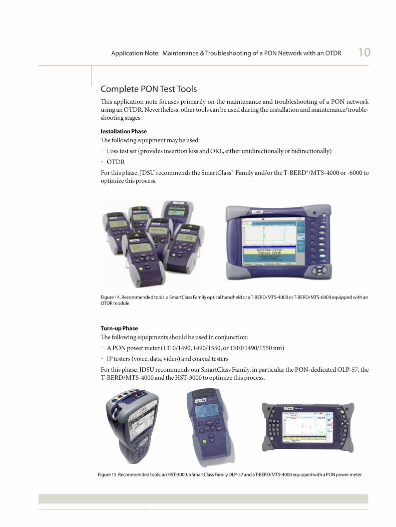
Complete PON Test ToolsThis application note focuses primarily on the maintenance and troubleshooting of a PON network using an OTDR. Nevertheless, other tools can be used during the installation and maintenance/trouble-shooting stages:
Installation PhaseThe following equipment may be used: ‒ Loss test set (provides insertion loss and ORL, either unidirectionally or bidirectionally) ‒ OTDRFor this phase, JDSU recommends the SmartClass™ Family and/or the T-BERD®/MTS-4000 or -6000 to optimize this process.
Figure 14. Recommended tools: a SmartClass Family optical handheld or a T-BERD/MTS-4000 or T-BERD/MTS-6000 equipped with an OTDR module
Turn-up PhaseThe following equipments should be used in conjunction: ‒ A PON power meter (1310/1490, 1490/1550, or 1310/1490/1550 nm) ‒ IP testers (voice, data, video) and coaxial testersFor this phase, JDSU recommends our SmartClass Family, in particular the PON-dedicated OLP-57, the T-BERD/MTS-4000 and the HST-3000 to optimize this process.
Figure 15. Recommended tools: an HST-3000, a SmartClass Family OLP-57 and a T-BERD/MTS-4000 equipped with a PON power meter

Application Note: Maintenance & Troubleshooting of a PON Network with an OTDR 11
Maintenance and Troubleshooting PhaseThe following equipments should be used in conjunction: ‒ A PON power meter (1310/1490, 1490/1550, or 1310/1490/1550 nm) ‒ A loss test set or an OTDR ‒ IP testers (voice, data, video) and coaxial testers
For this phase, JDSU recommends once more the material described above.
Figure 16. The Dedicated FTTx T-BERD/MTS-4000 Platform can be Equipped with a PON, an OTDR, and Triple-Play/WiFi Testing
*Refer to the JDSU Triple-Play book for more information, which is available on demand at: www.jdsu.com/products/communications-test-measurement/products/details/triple-play-service-deployment.html

Application Note: Maintenance & Troubleshooting of a PON Network with an OTDR 12
Product specifications and descriptions in this document subject to change without notice. © 2010 JDS Uniphase Corporation 30162937 000 0110 PONOTDR.AN.FOP.TM.AE January 2010
Test & Measurement Regional Sales
NORTH AMERICATEL: 1 866 228 3762FAX: +1 301 353 9216
LATIN AMERICATEL: +1 954 688 5660FAX: +1 954 345 4668
ASIA PACIFICTEL: +852 2892 0990FAX: +852 2892 0770
EMEATEL: +49 7121 86 2222FAX: +49 7121 86 1222
WEBSITE: www.jdsu.com/test