Embed Size (px)
Citation preview

Major 4a
Major 5aSoftware Option
Motorola MOTOTRBO
Software OptionMotorola MOTOTRBO

m4a_5a_motorola_mototrbo_eng (25.11.2016)- 2 -Kompetent für Elektroniksysteme
m4a_5a_motorola_mototrbo_eng (25.11.2016) - 3 -Kompetent für Elektroniksysteme
ContentsOrder Information 2General Information 3Important Settings at the Motorola MOTOTRBO 4Control Elements Major 5a 5Control Elements Major 4a 5Display Elements Major 4a / 5a 6Sockets Pinout Major 4a/5a 7Rearview Major 4a/5a 7RS232 Interface 8RS232 Cable for Flashing/Printing/Monitoring 8Configuration of the RS232 Interface 8Example Configurations 9Standard Keypad Assignment Major 5a 10Standard Keypad Assignment Major 4a 10Differences Major 4a - Major 5a 11Keypad Assignment Major 5a in Programming Mode 11Keypad Assignment Major 4a in Programming Mode 11Menu Structure 12Programming Short Call 15Configuration of the Software 15Changing the Assignment of Button Functions 16Customizing the Call Input 17Reset to Factory Defaults 17Transmit/Receive SDS (ab V3.03) 18Analog Channels 18ACK Request 18Default Group Call (since V3.06) 18Registerbelegung Major 4a, Major 5a 19Programmable Functions 22Technical Data 24General Safety Information 25Returning of Old Equipment 25
Page
Order Information
Order No. Description
681000.MOT Major 4a incl. Option MOTOTRBO
714000.MOT Major 5a incl. Option Motorola MOTOTRBO
903050 Distribution Frame (Überleitverteiler) DMR, 2-fold
903051 Distribution Frame (Überleitverteiler) DMR, 3-fold
Distribution Frame (Überleitverteiler) DMR, available on demand up to 9-fold
Attention: Power Supply Unit, Interface and cables are not included
900012 Power Supply Unit 230V/12V for Major 4a + Major 5a
900020 Interface-Audio-USB-RS232-RS485
900920 Connection Cable Motorola DM3400 <-> 900020, length ca. 1m
m4a_5a_motorola_mototrbo_eng (25.11.2016)- 2 -Kompetent für Elektroniksysteme
m4a_5a_motorola_mototrbo_eng (25.11.2016) - 3 -Kompetent für Elektroniksysteme
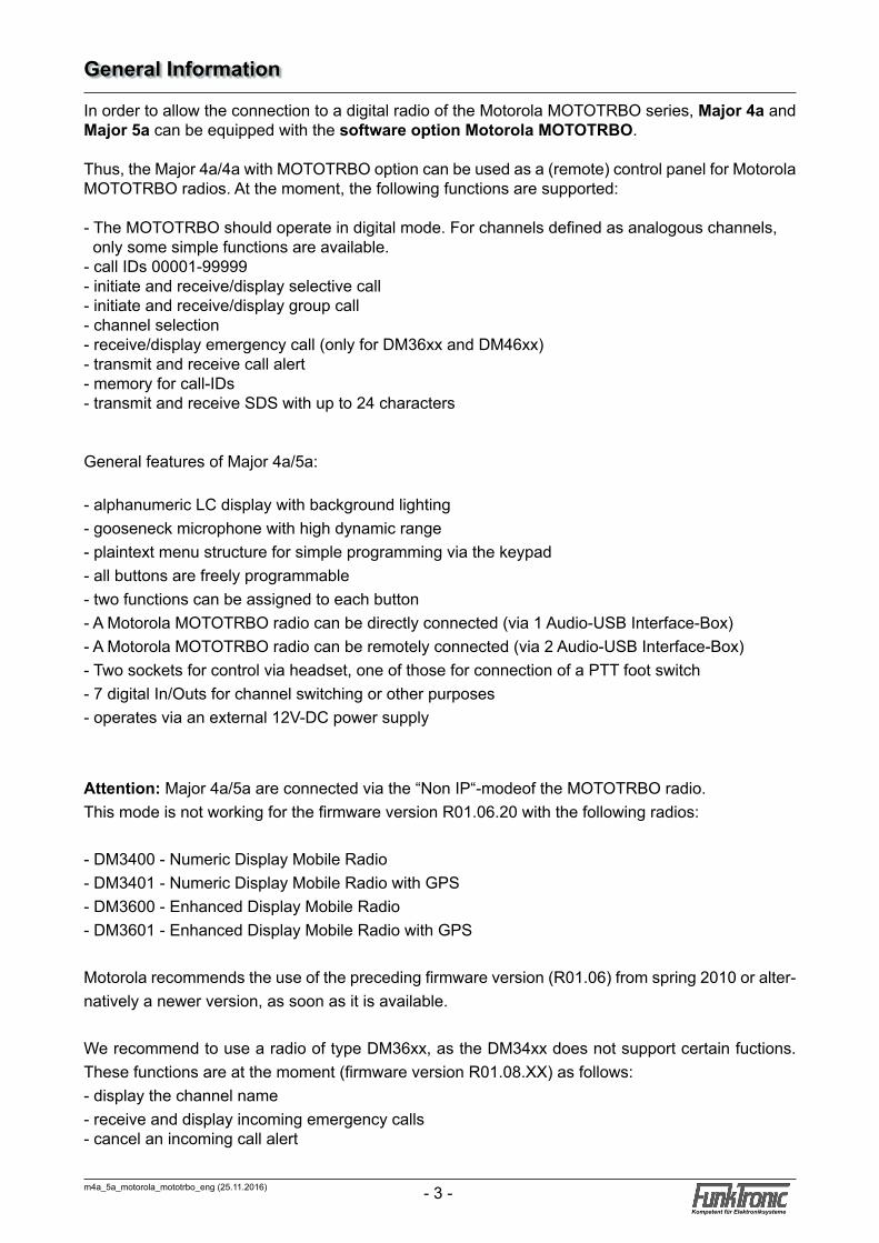
In order to allow the connection to a digital radio of the Motorola MOTOTRBO series, Major 4a and Major 5a can be equipped with the software option Motorola MOTOTRBO.
Thus, the Major 4a/4a with MOTOTRBO option can be used as a (remote) control panel for Motorola MOTOTRBO radios. At the moment, the following functions are supported:
- The MOTOTRBO should operate in digital mode. For channels defined as analogous channels, only some simple functions are available.- call IDs 00001-99999- initiate and receive/display selective call- initiate and receive/display group call- channel selection- receive/display emergency call (only for DM36xx and DM46xx)- transmit and receive call alert- memory for call-IDs- transmit and receive SDS with up to 24 characters
General features of Major 4a/5a:
- alphanumeric LC display with background lighting- gooseneck microphone with high dynamic range- plaintext menu structure for simple programming via the keypad- all buttons are freely programmable- two functions can be assigned to each button- A Motorola MOTOTRBO radio can be directly connected (via 1 Audio-USB Interface-Box)- A Motorola MOTOTRBO radio can be remotely connected (via 2 Audio-USB Interface-Box)- Two sockets for control via headset, one of those for connection of a PTT foot switch- 7 digital In/Outs for channel switching or other purposes- operates via an external 12V-DC power supply
Attention: Major 4a/5a are connected via the “Non IP“-modeof the MOTOTRBO radio.This mode is not working for the firmware version R01.06.20 with the following radios:
- DM3400 - Numeric Display Mobile Radio- DM3401 - Numeric Display Mobile Radio with GPS- DM3600 - Enhanced Display Mobile Radio- DM3601 - Enhanced Display Mobile Radio with GPS
Motorola recommends the use of the preceding firmware version (R01.06) from spring 2010 or alter-natively a newer version, as soon as it is available.
We recommend to use a radio of type DM36xx, as the DM34xx does not support certain fuctions. These functions are at the moment (firmware version R01.08.XX) as follows:- display the channel name- receive and display incoming emergency calls- cancel an incoming call alert
General Information
m4a_5a_motorola_mototrbo_eng (25.11.2016)- 4 -Kompetent für Elektroniksysteme
m4a_5a_motorola_mototrbo_eng (25.11.2016) - 5 -Kompetent für Elektroniksysteme
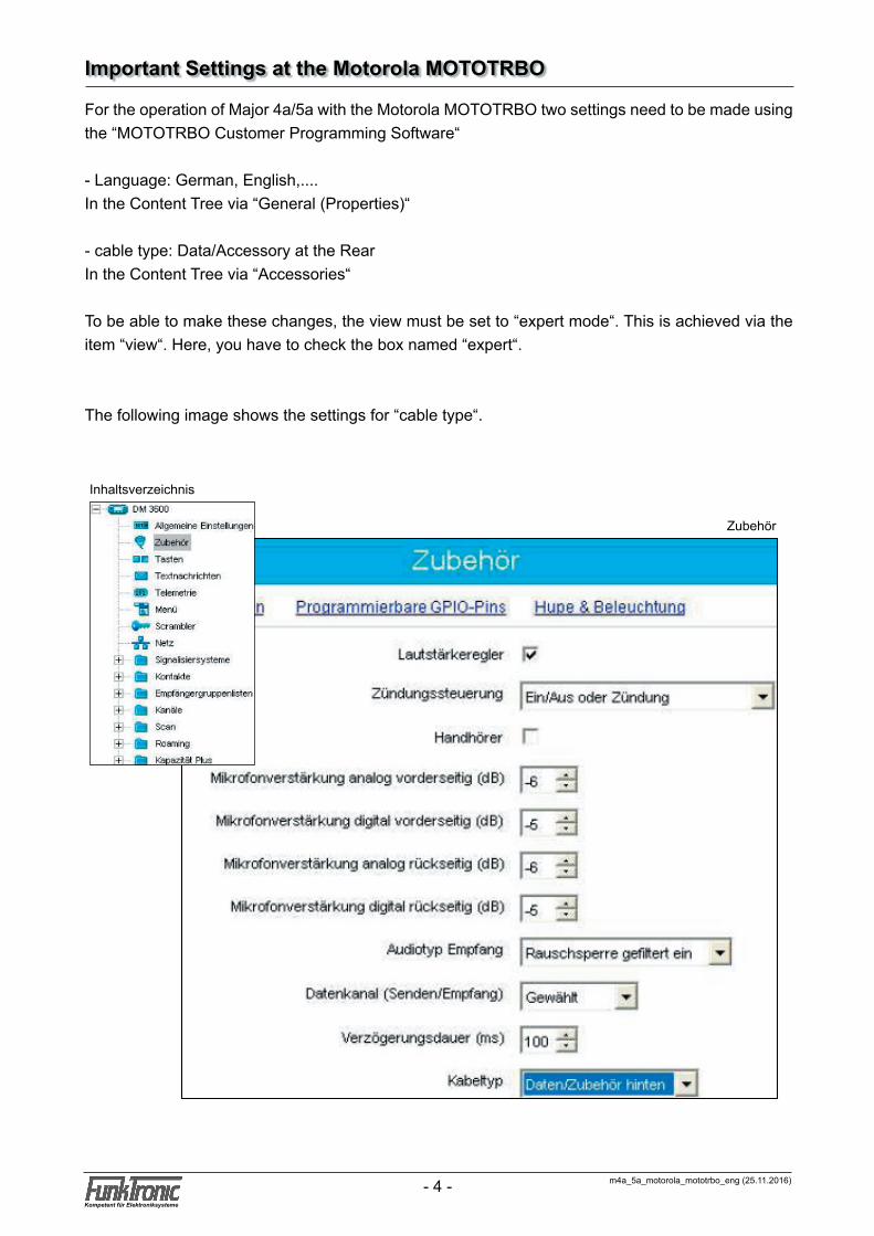
For the operation of Major 4a/5a with the Motorola MOTOTRBO two settings need to be made using the “MOTOTRBO Customer Programming Software“
- Language: German, English,....In the Content Tree via “General (Properties)“
- cable type: Data/Accessory at the RearIn the Content Tree via “Accessories“
To be able to make these changes, the view must be set to “expert mode“. This is achieved via the item “view“. Here, you have to check the box named “expert“.
The following image shows the settings for “cable type“.
Important Settings at the Motorola MOTOTRBO
Inhaltsverzeichnis
Zubehör

m4a_5a_motorola_mototrbo_eng (25.11.2016)- 4 -Kompetent für Elektroniksysteme
m4a_5a_motorola_mototrbo_eng (25.11.2016) - 5 -Kompetent für Elektroniksysteme
Control Elements Major 4a
handpiece with PTT button
gooseneck microphone
loudspeaker (LS) button
call buttonshort call button PTT button
LC display
function buttons
special buttons
status LEDs
Control Elements Major 5a
loudspeaker
gooseneck microphone
loudspeaker buttoncall button
short call button
PTT button
LC display
status LEDs
volume button
m4a_5a_motorola_mototrbo_eng (25.11.2016)- 6 -Kompetent für Elektroniksysteme
m4a_5a_motorola_mototrbo_eng (25.11.2016) - 7 -Kompetent für Elektroniksysteme
Display Elements Major 4a / 5a
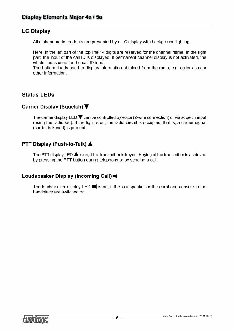
LC Display
All alphanumeric readouts are presented by a LC display with background lighting.
Here, in the left part of the top line 14 digits are reserved for the channel name. In the right part, the input of the call ID is displayed. If permanent channel display is not activated, the whole line is used for the call ID input.The bottom line is used to display information obtained from the radio, e.g. caller alias or other information.
Status LEDs
Carrier Display (Squelch)
The carrier display LED can be controlled by voice (2-wire connection) or via squelch input (using the radio set). If the light is on, the radio circuit is occupied, that is, a carrier signal (carrier is keyed) is present.
PTT Display (Push-to-Talk)
The PTT display LED is on, if the transmitter is keyed. Keying of the transmitter is achieved by pressing the PTT button during telephony or by sending a call.
Loudspeaker Display (Incoming Call)
The loudspeaker display LED is on, if the loudspeaker or the earphone capsule in the handpiece are switched on.
m4a_5a_motorola_mototrbo_eng (25.11.2016)- 6 -Kompetent für Elektroniksysteme
m4a_5a_motorola_mototrbo_eng (25.11.2016) - 7 -Kompetent für Elektroniksysteme
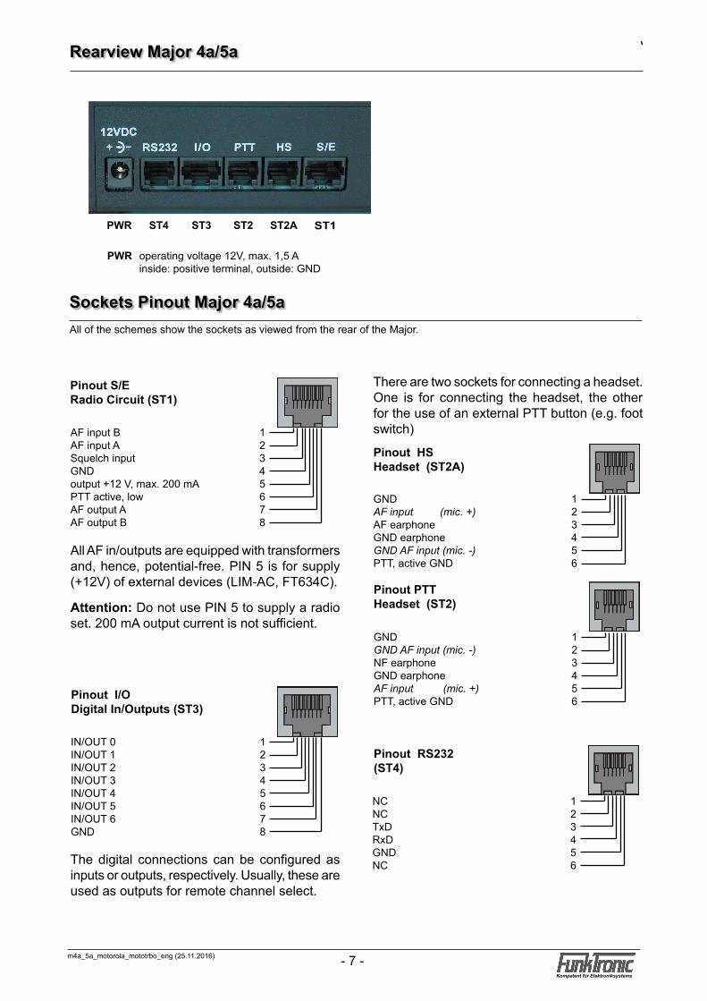
PWR operating voltage 12V, max. 1,5 A inside: positive terminal, outside: GND
Rearview Major 4a/5a
Pinout I/ODigital In/Outputs (ST3)
IN/OUT 0 1IN/OUT 1 2IN/OUT 2 3IN/OUT 3 4IN/OUT 4 5IN/OUT 5 6IN/OUT 6 7GND 8
Pinout RS232 (ST4)
NC 1NC 2TxD 3RxD 4GND 5NC 6
Pinout S/E Radio Circuit (ST1)
AF input B 1AF input A 2Squelch input 3GND 4output +12 V, max. 200 mA 5PTT active, low 6AF output A 7AF output B 8
Pinout PTT Headset (ST2)
GND 1GND AF input (mic. -) 2NF earphone 3GND earphone 4AF input (mic. +) 5PTT, active GND 6
Sockets Pinout Major 4a/5a
All AF in/outputs are equipped with transformers and, hence, potential-free. PIN 5 is for supply (+12V) of external devices (LIM-AC, FT634C).
Attention: Do not use PIN 5 to supply a radio set. 200 mA output current is not sufficient.
There are two sockets for connecting a headset. One is for connecting the headset, the other for the use of an external PTT button (e.g. foot switch)
The digital connections can be configured as inputs or outputs, respectively. Usually, these are used as outputs for remote channel select.
All of the schemes show the sockets as viewed from the rear of the Major.
ST1ST2AST4 ST2ST3PWR
Pinout HSHeadset (ST2A)
GND 1AF input (mic. +) 2AF earphone 3GND earphone 4GND AF input (mic. -) 5PTT, active GND 6

m4a_5a_motorola_mototrbo_eng (25.11.2016)- 8 -Kompetent für Elektroniksysteme
m4a_5a_motorola_mototrbo_eng (25.11.2016) - 9 -Kompetent für Elektroniksysteme
5 GND
ST4 RS232 Interface
RS232 Interface
Pinout RS232 ST4
1 2 3 4 5 6
RS232 Cable for Flashing/Printing/Monitoring
7 GND
2 TxD RS2323 RxD RS232
RS232 25pin connector on computer RS232 socket on Major
TxDRxDGND
Pinout RS232 ST4
1 2 3 4 5 6
TxDRxDGND
3 TxD RS232
2 RxD RS232
RS232 9pin connector on computer RS232 socket on Major
Configuration of the RS232 Interface9600 Baud, 8 data bits, no parity, 1 stop bit, no protocol
m4a_5a_motorola_mototrbo_eng (25.11.2016)- 8 -Kompetent für Elektroniksysteme
m4a_5a_motorola_mototrbo_eng (25.11.2016) - 9 -Kompetent für Elektroniksysteme
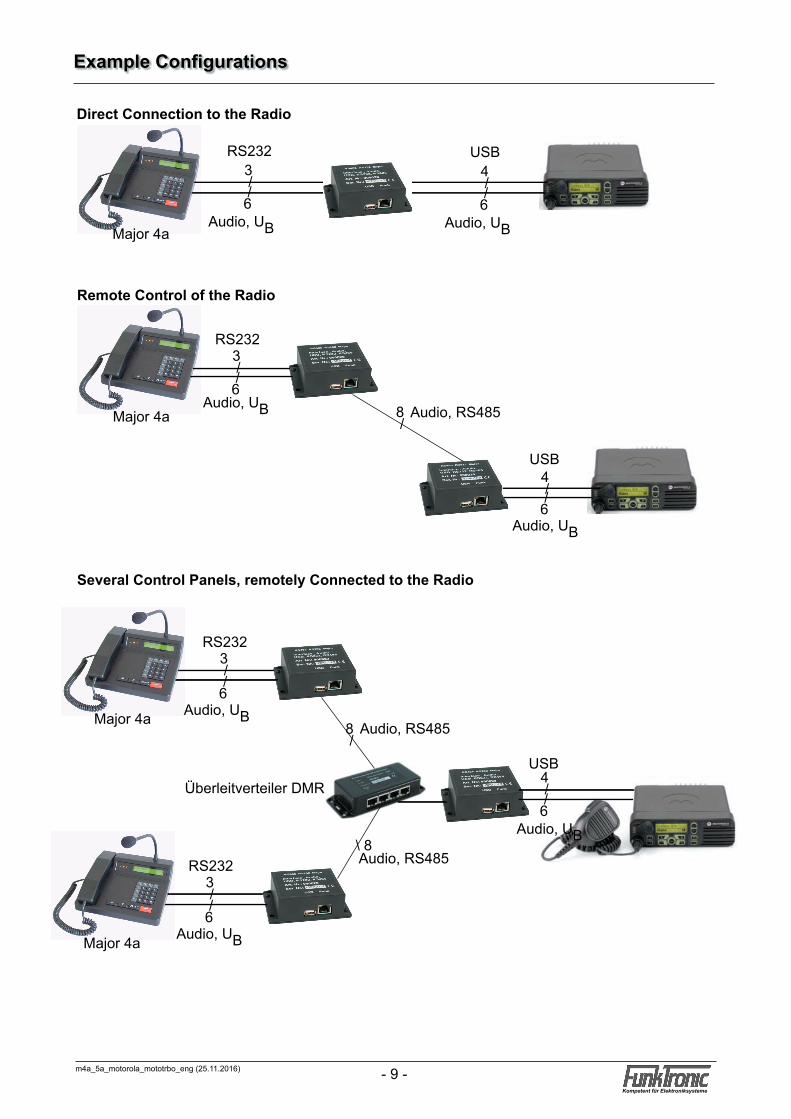
RS232
Audio, UB Audio, RS485
3 / /6
Remote Control of the Radio
Several Control Panels, remotely Connected to the Radio
8 /
USB4 / /6
Major 4a
Audio, UB
Direct Connection to the Radio
Major 4a
USB
Audio, UB
4 / /6
RS232
Audio, UB
3 / /6
Audio, RS485
Audio, RS485
RS232
Audio, UB
3 / /6
RS232
Audio, UB
3 / /6
8 /
USB
Audio, UB
4 / /6
\ 8
Major 4a
Major 4a
Überleitverteiler DMR
Example Configurations

m4a_5a_motorola_mototrbo_eng (25.11.2016)- 10 -Kompetent für Elektroniksysteme
m4a_5a_motorola_mototrbo_eng (25.11.2016) - 11 -Kompetent für Elektroniksysteme
0 ... 9 : number input (call, channel, status...) * short : transfer ID-code to call input* long : delete whole call input# short : scroll through ID-code memory# long : delete ID-code from memory� : channel input : PTT gooseneck mic / status : short: toggle selective call / group call long: send call alert to call ID
: volume control
��¡1 3
548
2
09
*7
6
#
A
E F
+- ��S1
¡BS2
¡CS3
¡DS4
Standard Keypad Assignment Major 4a
1 3548
2
09
*7
6
#
A B C
D E F
Standard Keypad Assignment Major 5a
Comparable to Major 4a, but without the additional buttons S1...S4 and F1...F4.
+-
m4a_5a_motorola_mototrbo_eng (25.11.2016)- 10 -Kompetent für Elektroniksysteme
m4a_5a_motorola_mototrbo_eng (25.11.2016) - 11 -Kompetent für Elektroniksysteme
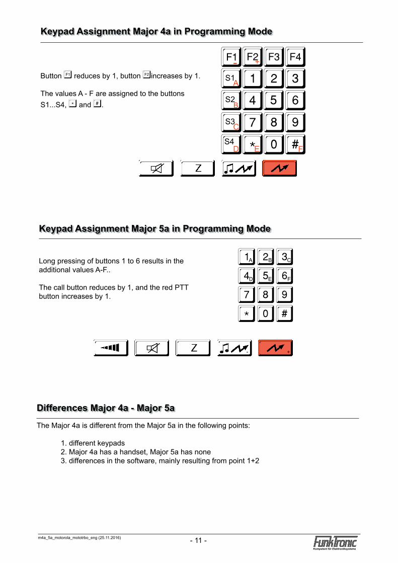
Keypad Assignment Major 4a in Programming Mode
Button � reduces by 1, button �increases by 1.
The values A - F are assigned to the buttons S1...S4, * and #.
��¡1 3
548
2
09
*7
6
#
A
E F
+- ��S1
¡BS2
¡CS3
¡DS4
1 3548
2
09
*7
6
#
A B C
D E F
Keypad Assignment Major 5a in Programming Mode
Long pressing of buttons 1 to 6 results in the additional values A-F..
The call button reduces by 1, and the red PTT button increases by 1.
+-
The Major 4a is different from the Major 5a in the following points:
1. different keypads 2. Major 4a has a handset, Major 5a has none 3. differences in the software, mainly resulting from point 1+2
Differences Major 4a - Major 5a
m4a_5a_motorola_mototrbo_eng (25.11.2016)- 12 -Kompetent für Elektroniksysteme
m4a_5a_motorola_mototrbo_eng (25.11.2016) - 13 -Kompetent für Elektroniksysteme
select number:
EEPROM programming : F4Next menu : F3
Software Version : F4Next menu : F3
Level settings : F4Next menu : F3
Register: Software: Major 4a V1.24Date : 23.09.04
Poti-Nr. (1-6):
Register: 000Code 12345
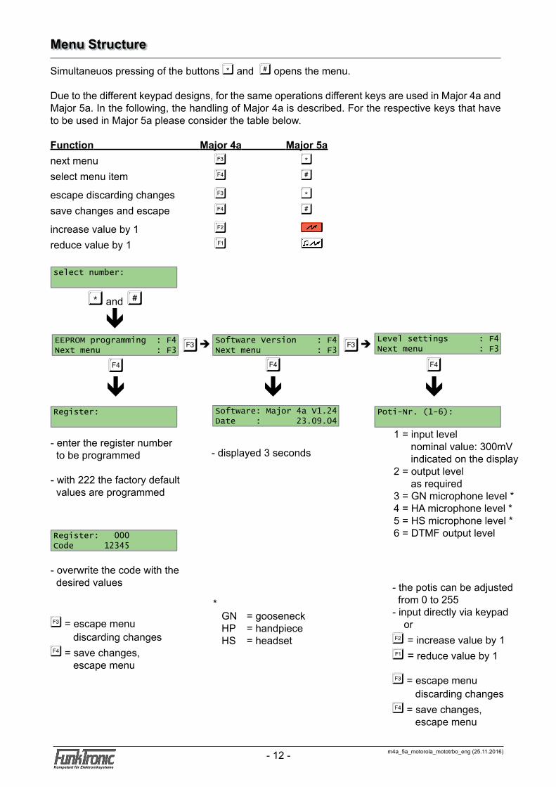
* GN = gooseneck HP = handpiece HS = headset
Menu Structure
Simultaneuos pressing of the buttons * and # opens the menu.
Due to the different keypad designs, for the same operations different keys are used in Major 4a and Major 5a. In the following, the handling of Major 4a is described. For the respective keys that have to be used in Major 5a please consider the table below.
Function Major 4a Major 5anext menu � *select menu item � #
escape discarding changes � *save changes and escape � #
increase value by 1 �reduce value by 1 �
- enter the register number to be programmed
- with 222 the factory default values are programmed
- overwrite the code with the desired values
1 = input level nominal value: 300mV indicated on the display2 = output level as required3 = GN microphone level *4 = HA microphone level *5 = HS microphone level *6 = DTMF output level
* and #
�
êè �è
ê ê ê� � �
- displayed 3 seconds
- the potis can be adjusted from 0 to 255- input directly via keypad or� = increase value by 1� = reduce value by 1
� = escape menu discarding changes� = save changes, escape menu
� = escape menu discarding changes� = save changes, escape menu
m4a_5a_motorola_mototrbo_eng (25.11.2016)- 12 -Kompetent für Elektroniksysteme
m4a_5a_motorola_mototrbo_eng (25.11.2016) - 13 -Kompetent für Elektroniksysteme
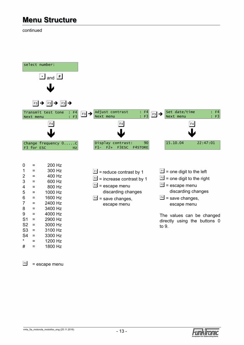
0 = 200 Hz1 = 300 Hz2 = 400 Hz3 = 600 Hz4 = 800 Hz5 = 1000 Hz6 = 1600 Hz7 = 2400 Hz8 = 3400 Hz9 = 4000 HzS1 = 2900 HzS2 = 3000 HzS3 = 3100 HzS4 = 3300 Hz* = 1200 Hz# = 1800 Hz
� = escape menu
* and #
ê
continued
�è�è�è
ê�
�è
ê�
� = reduce contrast by 1� = increase contrast by 1� = escape menu discarding changes� = save changes, escape menu
ê�
�è
� = one digit to the left� = one digit to the right� = escape menu discarding changes� = save changes, escape menu The values can be changed directly using the buttons 0 to 9.
Menu Structure
select number:
Transmit test tone : F4Next menu : F3
Change frequency 0.....CF3 for ESC Hz
Adjust contrast : F4Next menu : F3
Display contrast: 90F1- F2+ F3ESC F4STORE
Set date/time : F4Next menu : F3
15.10.04 22:47:01
m4a_5a_motorola_mototrbo_eng (25.11.2016)- 14 -Kompetent für Elektroniksysteme
m4a_5a_motorola_mototrbo_eng (25.11.2016) - 15 -Kompetent für Elektroniksysteme
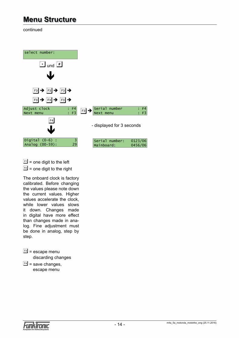
The onboard clock is factory calibrated. Before changing the values please note down the current values. Higher values accelerate the clock, while lower values slows it down. Changes made in digital have more effect than changes made in ana-log. Fine adjustment must be done in analog, step by step.
* und #
ê
continued
�è�è�è
ê�
�è
- displayed for 3 seconds
�è�è�è
� = escape menu discarding changes� = save changes, escape menu
� = one digit to the left� = one digit to the right
Menu Structure
select number:
Adjust clock : F4Next menu : F3
Digital (0-6) : 3Analog (00-59): 29
Serial number : F4Next menu : F3
Serial number: 0123/06Mainboard: 0456/06
m4a_5a_motorola_mototrbo_eng (25.11.2016)- 14 -Kompetent für Elektroniksysteme
m4a_5a_motorola_mototrbo_eng (25.11.2016) - 15 -Kompetent für Elektroniksysteme
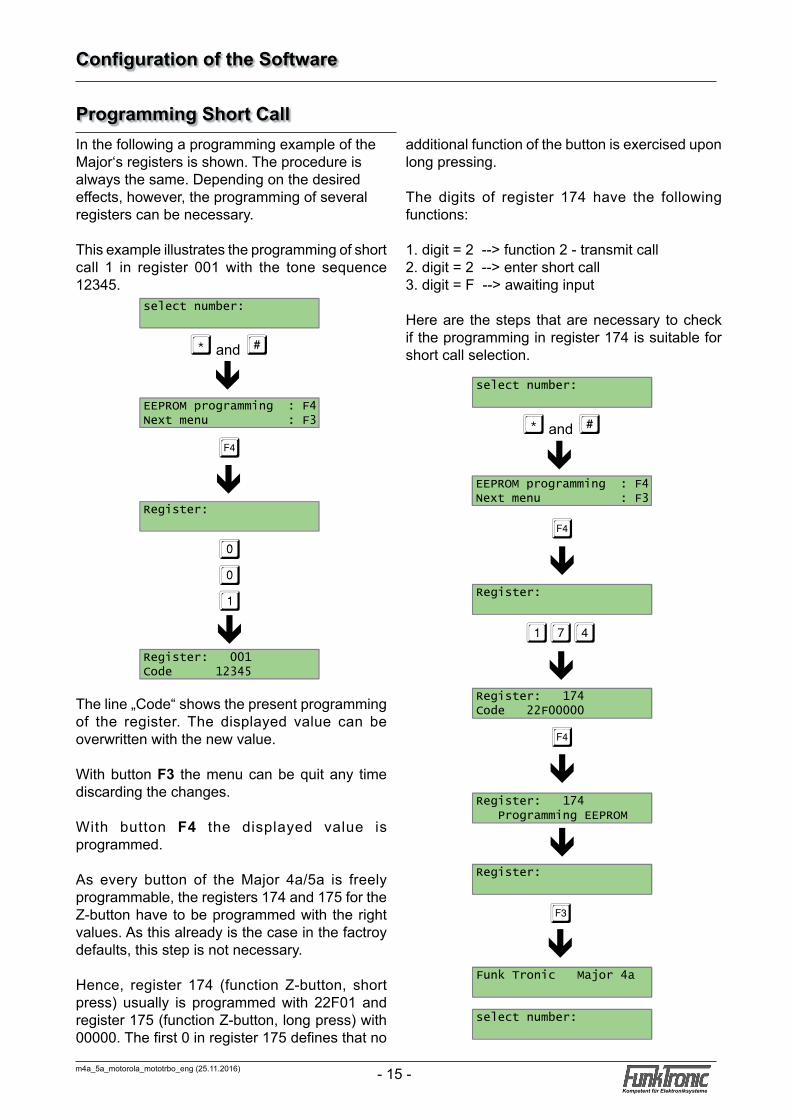
additional function of the button is exercised upon long pressing.
The digits of register 174 have the following functions:
1. digit = 2 --> function 2 - transmit call2. digit = 2 --> enter short call3. digit = F --> awaiting input
Here are the steps that are necessary to check if the programming in register 174 is suitable for short call selection.
Configuration of the Software
Programming Short CallIn the following a programming example of the Major‘s registers is shown. The procedure is always the same. Depending on the desired effects, however, the programming of several registers can be necessary.
This example illustrates the programming of short call 1 in register 001 with the tone sequence 12345.
The line „Code“ shows the present programming of the register. The displayed value can be overwritten with the new value.
With button F3 the menu can be quit any time discarding the changes.
With button F4 the displayed value is programmed.
As every button of the Major 4a/5a is freely programmable, the registers 174 and 175 for the Z-button have to be programmed with the right values. As this already is the case in the factroy defaults, this step is not necessary.
Hence, register 174 (function Z-button, short press) usually is programmed with 22F01 and register 175 (function Z-button, long press) with 00000. The first 0 in register 175 defines that no
* and #
1
ê
�
74
ê
ê
�
ê
ê
ê�
select number:
Register:
Register: 174Code 22F00000
Register: 174 Programming EEPROM
Register:
Funk Tronic Major 4a
select number:
* and #
0
ê
�
01
ê
ê
select number:
EEPROM programming : F4Next menu : F3
Register:
Register: 001Code 12345
EEPROM programming : F4Next menu : F3
m4a_5a_motorola_mototrbo_eng (25.11.2016)- 16 -Kompetent für Elektroniksysteme
m4a_5a_motorola_mototrbo_eng (25.11.2016) - 17 -Kompetent für Elektroniksysteme
Changing the Assignment of Button Functions
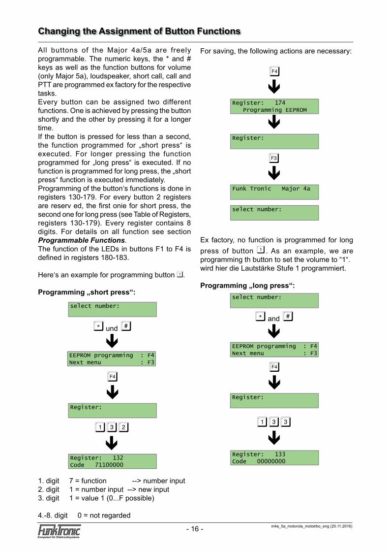
All buttons of the Major 4a/5a are freely programmable. The numeric keys, the * and # keys as well as the function buttons for volume (only Major 5a), loudspeaker, short call, call and PTT are programmed ex factory for the respective tasks.Every button can be assigned two different functions. One is achieved by pressing the button shortly and the other by pressing it for a longer time.If the button is pressed for less than a second, the function programmed for „short press“ is executed. For longer pressing the function programmed for „long press“ is executed. If no function is programmed for long press, the „short press“ function is executed immediately.Programming of the button‘s functions is done in registers 130-179. For every button 2 registers are reserv ed, the first onie for short press, the second one for long press (see Table of Registers, registers 130-179). Every register contains 8 digits. For details on all function see section Programmable Functions.The function of the LEDs in buttons F1 to F4 is defined in registers 180-183.
Here‘s an example for programming button 1.
Programming „short press“:
1. digit 7 = function --> number input2. digit 1 = number input --> new input3. digit 1 = value 1 (0...F possible)
4.-8. digit 0 = not regarded
Ex factory, no function is programmed for long press of button 1 . As an example, we are programming th button to set the volume to “1“.wird hier die Lautstärke Stufe 1 programmiert.
Programming „long press“:
* und #
1
ê
�
32
ê
ê
select number:
Register:
Register: 132Code 71100000
�
ê
For saving, the following actions are necessary:
EEPROM programming : F4Next menu : F3
ê
ê�
Register: 174 Programming EEPROM
Register:
Funk Tronic Major 4a
select number:
* and #ê
�
ê
select number:
EEPROM programming : F4Next menu : F3
Register:
133
êRegister: 133Code 00000000
m4a_5a_motorola_mototrbo_eng (25.11.2016)- 16 -Kompetent für Elektroniksysteme
m4a_5a_motorola_mototrbo_eng (25.11.2016) - 17 -Kompetent für Elektroniksysteme
Customizing the Call Input
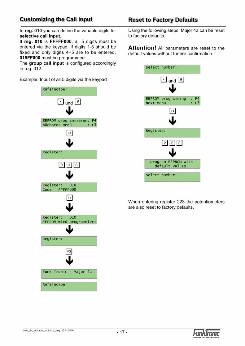
In reg. 010 you can define the variable digits for selective call input.If reg. 010 is FFFFF000, all 5 digits must be entered via the keypad. If digits 1-3 should be fixed and only digits 4+5 are to be entered, 015FF000 must be programmed.The group call input is configured accordingly in reg. 012.
Example: Input of all 5 digits via the keypad
* und #
0
ê
�
10
ê
ê
�
ê
ê
ê�
Rufeingabe:
EEPROM programmieren: F4nächstes Menü : F3
Register:
Register: 010Code FFFFF000
Register: 010EEPROM wird programmiert
Register:
Funk Tronic Major 4a
Rufeingabe:
Reset to Factory DefaultsUsing the following steps, Major 4a can be reset to factory defaults.
Attention! All parameters are reset to the default values without further confirmation.
When entering register 223 the potentiometers are also reset to factory defaults.
* and #
2
ê
�
22
ê
ê
select number:
EEPROM programming : F4Next menu : F3
Register:
program EEPROM with default values
select number:
m4a_5a_motorola_mototrbo_eng (25.11.2016)- 18 -Kompetent für Elektroniksysteme
m4a_5a_motorola_mototrbo_eng (25.11.2016) - 19 -Kompetent für Elektroniksysteme
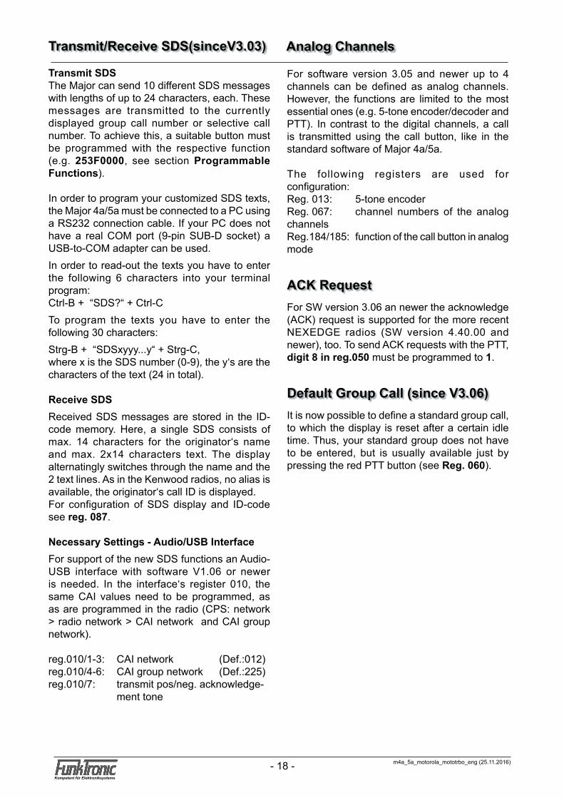
Transmit/Receive SDS(sinceV3.03)
Transmit SDSThe Major can send 10 different SDS messages with lengths of up to 24 characters, each. These messages are transmitted to the currently displayed group call number or selective call number. To achieve this, a suitable button must be programmed with the respective function (e.g. 253F0000, see section Programmable Functions).
In order to program your customized SDS texts, the Major 4a/5a must be connected to a PC using a RS232 connection cable. If your PC does not have a real COM port (9-pin SUB-D socket) a USB-to-COM adapter can be used.In order to read-out the texts you have to enter the following 6 characters into your terminal program:Ctrl-B + “SDS?“ + Ctrl-CTo program the texts you have to enter the following 30 characters:Strg-B + “SDSxyyy...y“ + Strg-C,where x is the SDS number (0-9), the y‘s are the characters of the text (24 in total).
Receive SDSReceived SDS messages are stored in the ID-code memory. Here, a single SDS consists of max. 14 characters for the originator‘s name and max. 2x14 characters text. The display alternatingly switches through the name and the 2 text lines. As in the Kenwood radios, no alias is available, the originator‘s call ID is displayed.For configuration of SDS display and ID-code see reg. 087.
Necessary Settings - Audio/USB InterfaceFor support of the new SDS functions an Audio-USB interface with software V1.06 or newer is needed. In the interface‘s register 010, the same CAI values need to be programmed, as as are programmed in the radio (CPS: network > radio network > CAI network and CAI group network).
reg.010/1-3: CAI network (Def.:012)reg.010/4-6: CAI group network (Def.:225)reg.010/7: transmit pos/neg. acknowledge- ment tone
For software version 3.05 and newer up to 4 channels can be defined as analog channels. However, the functions are limited to the most essential ones (e.g. 5-tone encoder/decoder and PTT). In contrast to the digital channels, a call is transmitted using the call button, like in the standard software of Major 4a/5a.
The following registers are used for configuration:Reg. 013: 5-tone encoderReg. 067: channel numbers of the analog channelsReg.184/185: function of the call button in analog mode
ACK RequestFor SW version 3.06 an newer the acknowledge (ACK) request is supported for the more recent NEXEDGE radios (SW version 4.40.00 and newer), too. To send ACK requests with the PTT, digit 8 in reg.050 must be programmed to 1.
Default Group Call (since V3.06)It is now possible to define a standard group call, to which the display is reset after a certain idle time. Thus, your standard group does not have to be entered, but is usually available just by pressing the red PTT button (see Reg. 060).
Analog Channels

m4a_5a_motorola_mototrbo_eng (25.11.2016)- 18 -Kompetent für Elektroniksysteme
m4a_5a_motorola_mototrbo_eng (25.11.2016) - 19 -Kompetent für Elektroniksysteme
000 short call 0-9-009 1st digit: 0 = group call, 1 = selective call 2nd-6th digit: variable digits, that must be entered
010 selective call register 1st-5th digit: digits for selective call variable digits are coded as F 6th digit: display the programmed group call if digits 1-5 are not programmed y/n (1/0)
011 general configuration 1st digit: language 0 = German 1 = English 2 = French 3 = Dutch 4 = Italian 5 = Czech 4th digit: RS232 monitor is on/off (1/0) at power-on 5th digit: pressing *+# (or F1+F4) is neces sary for n*1s to enter programming mode 0 = immediately F = disabled
012 group call register 1st-5th digit: digits for group call variable digits are coded as F 6th digit: display the programmed group call if digits 1-5 are not programmed y/n (1/0)
013 5-tone encoder (analog channels) 1st-5th digit: e-tone sequence, variable digits are coded as F 6th-8th digit: must be coded as 0
020 decoder 1021 decoder 2022 decoder 3023 decoder 4024 decoder 5025 decoder 6026 decoder 7027 decoder 8028 decoder 9029 decoder 10020-029: 1st-7thdigit: decoder, program unused digits with an F
8thdigit: 0 = decoder off 1 = decoder on
030 configuration 1 for decoder 1031 configuration 1 für decoder 2032 configuration 1 für decoder 3033 configuration 1 für decoder 4034 configuration 1 für decoder 5035 configuration 1 für decoder 6036 configuration 1 für decoder 7037 configuration 1 für decoder 8038 configuration 1 für decoder 9039 configuration 1 für decoder 10030-039: 1stdigit: alarm tone type 2nddigit: alarm tone duration n*200ms 3rddigit: alarm tone volume (0-9, A..F=Offset +0...5) 4thdigit: call volume duration n*200ms 5thdigit: call volume
040 configuration 2 für decoder 1041 configuration 2 für decoder 2042 configuration 2 für decoder 3043 configuration 2 für decoder 4044 configuration 2 für decoder 5045 configuration 2 für decoder 6046 configuration 2 für decoder 7047 configuration 2 für decoder 8048 configuration 2 für decoder 9049 configuration 2 für decoder 10040-049: 1stdigit: ID-mode of call 0 = 5-tone sequence 2nddigit: switching output: number: 0 (none), 1-7 3rddigit: switching output: 0(off) F(on) for a variable time: 1-D (0-13)s 4thdigit: acknowledgement: 0 = no acknowledgement 1 = acknowledgement 2 = single tone 3 = own ID-code 4 = received ID-code 5thdigit: Loudspeaker / LED: 0 = no action 1 = LS on 2 = LED fashes 3 = LS on + LED flashes
Register Programming Major 4a, Major 5a
reg. functionreg. function
m4a_5a_motorola_mototrbo_eng (25.11.2016)- 20 -Kompetent für Elektroniksysteme
m4a_5a_motorola_mototrbo_eng (25.11.2016) - 21 -Kompetent für Elektroniksysteme
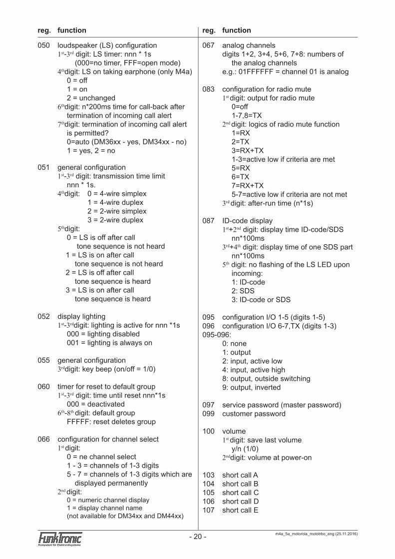
050 loudspeaker (LS) configuration 1st-3rd digit: LS timer: nnn * 1s (000=no timer, FFF=open mode) 4thdigit: LS on taking earphone (only M4a) 0 = off 1 = on 2 = unchanged 6thdigit: n*200ms time for call-back after termination of incoming call alert 7thdigit: termination of incoming call alert is permitted? 0=auto (DM36xx - yes, DM34xx - no) 1 = yes, 2 = no
051 general configuration 1st-3rd digit: transmission time limit nnn * 1s. 4thdigit: 0 = 4-wire simplex 1 = 4-wire duplex 2 = 2-wire simplex 3 = 2-wire duplex 5thdigit: 0 = LS is off after call tone sequence is not heard 1 = LS is on after call tone sequence is not heard 2 = LS is off after call tone sequence is heard 3 = LS is on after call tone sequence is heard
052 display lighting 1st-3rddigit: lighting is active for nnn *1s 000 = lighting disabled 001 = lighting is always on
055 general configuration 3rddigit: key beep (on/off = 1/0)
060 timer for reset to default group 1st-3rd digit: time until reset nnn*1s 000 = deactivated 6th-8th digit: default group FFFFF: reset deletes group
066 configuration for channel select 1st digit: 0 = ne channel select 1 - 3 = channels of 1-3 digits 5 - 7 = channels of 1-3 digits which are displayed permanently 2nd digit: 0 = numeric channel display 1 = display channel name (not available for DM34xx and DM44xx)
067 analog channels digits 1+2, 3+4, 5+6, 7+8: numbers of the analog channels e.g.: 01FFFFFF = channel 01 is analog
083 configuration for radio mute 1st digit: output for radio mute 0=off 1-7,8=TX 2nd digit: logics of radio mute function 1=RX 2=TX 3=RX+TX 1-3=active low if criteria are met 5=RX 6=TX 7=RX+TX 5-7=active low if criteria are not met 3rd digit: after-run time (n*1s)
087 ID-code display 1st+2nd digit: display time ID-code/SDS nn*100ms 3rd+4th digit: display time of one SDS part nn*100ms 5th digit: no flashing of the LS LED upon incoming: 1: ID-code 2: SDS 3: ID-code or SDS
095 configuration I/O 1-5 (digits 1-5)096 configuration I/O 6-7,TX (digits 1-3)095-096: 0: none 1: output 2: input, active low 4: input, active high 8: output, outside switching 9: output, inverted
097 service password (master password)099 customer password
100 volume 1st digit: save last volume y/n (1/0) 2nddigit: volume at power-on
103 short call A104 short call B105 short call C106 short call D107 short call E
reg. function reg. function
m4a_5a_motorola_mototrbo_eng (25.11.2016)- 20 -Kompetent für Elektroniksysteme
m4a_5a_motorola_mototrbo_eng (25.11.2016) - 21 -Kompetent für Elektroniksysteme
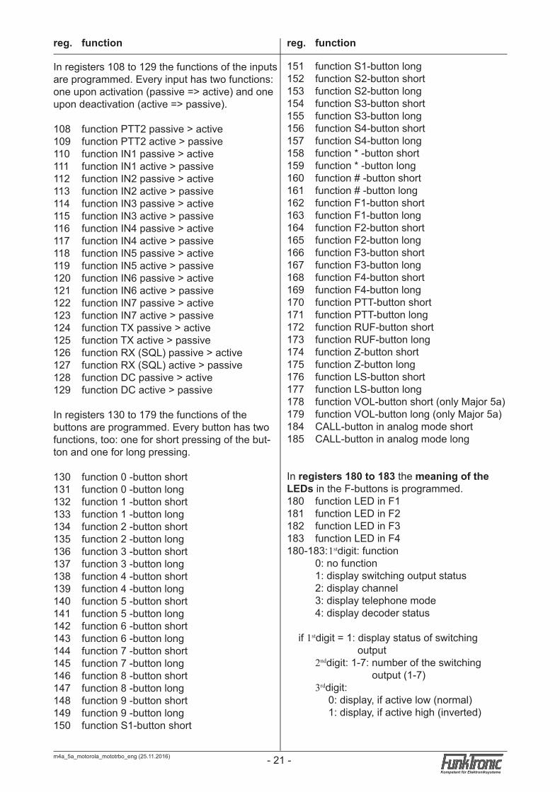
In registers 108 to 129 the functions of the inputs are programmed. Every input has two functions: one upon activation (passive => active) and one upon deactivation (active => passive).
108 function PTT2 passive > active109 function PTT2 active > passive110 function IN1 passive > active111 function IN1 active > passive112 function IN2 passive > active113 function IN2 active > passive114 function IN3 passive > active115 function IN3 active > passive116 function IN4 passive > active117 function IN4 active > passive118 function IN5 passive > active119 function IN5 active > passive120 function IN6 passive > active121 function IN6 active > passive122 function IN7 passive > active123 function IN7 active > passive124 function TX passive > active125 function TX active > passive126 function RX (SQL) passive > active127 function RX (SQL) active > passive128 function DC passive > active129 function DC active > passive
In registers 130 to 179 the functions of the buttons are programmed. Every button has two functions, too: one for short pressing of the but-ton and one for long pressing.
130 function 0 -button short131 function 0 -button long132 function 1 -button short133 function 1 -button long134 function 2 -button short135 function 2 -button long136 function 3 -button short137 function 3 -button long138 function 4 -button short139 function 4 -button long140 function 5 -button short141 function 5 -button long142 function 6 -button short143 function 6 -button long144 function 7 -button short145 function 7 -button long146 function 8 -button short147 function 8 -button long148 function 9 -button short149 function 9 -button long150 function S1-button short
151 function S1-button long152 function S2-button short153 function S2-button long154 function S3-button short155 function S3-button long156 function S4-button short157 function S4-button long158 function * -button short159 function * -button long160 function # -button short161 function # -button long162 function F1-button short163 function F1-button long164 function F2-button short165 function F2-button long166 function F3-button short167 function F3-button long168 function F4-button short169 function F4-button long170 function PTT-button short171 function PTT-button long172 function RUF-button short173 function RUF-button long174 function Z-button short175 function Z-button long176 function LS-button short177 function LS-button long178 function VOL-button short (only Major 5a)179 function VOL-button long (only Major 5a)184 CALL-button in analog mode short185 CALL-button in analog mode long
In registers 180 to 183 the meaning of the LEDs in the F-buttons is programmed.180 function LED in F1181 function LED in F2182 function LED in F3183 function LED in F4180-183: 1stdigit: function 0: no function 1: display switching output status 2: display channel 3: display telephone mode 4: display decoder status
if 1stdigit = 1: display status of switching output 2nddigit: 1-7: number of the switching output (1-7) 3rddigit: 0: display, if active low (normal) 1: display, if active high (inverted)
reg. function reg. function
m4a_5a_motorola_mototrbo_eng (25.11.2016)- 22 -Kompetent für Elektroniksysteme
m4a_5a_motorola_mototrbo_eng (25.11.2016) - 23 -Kompetent für Elektroniksysteme
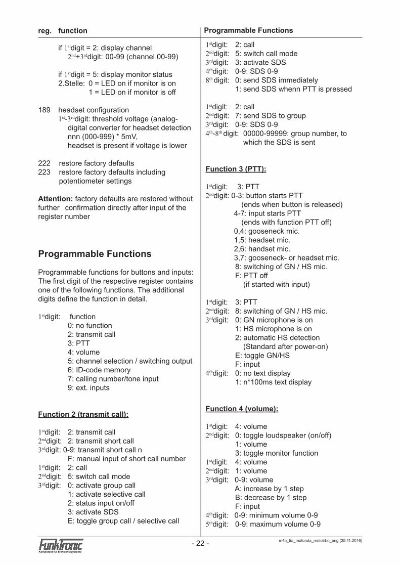
if 1stdigit = 2: display channel 2nd+3rddigit: 00-99 (channel 00-99)
if 1stdigit = 5: display monitor status 2.Stelle: 0 = LED on if monitor is on 1 = LED on if monitor is off
189 headset configuration 1st-3rddigit: threshold voltage (analog- digital converter for headset detection nnn (000-999) * 5mV, headset is present if voltage is lower
222 restore factory defaults 223 restore factory defaults including potentiometer settings
Attention: factory defaults are restored without further confirmation directly after input of the register number
Programmable Functions
Programmable functions for buttons and inputs:The first digit of the respective register contains one of the following functions. The additional digits define the function in detail.
1stdigit: function 0: no function 2: transmit call 3: PTT 4: volume 5: channel selection / switching output 6: ID-code memory 7: calling number/tone input 9: ext. inputs
Function 2 (transmit call):
1stdigit: 2: transmit call2nddigit: 2: transmit short call3rddigit: 0-9: transmit short call n F: manual input of short call number 1stdigit: 2: call2nddigit: 5: switch call mode3rddigit: 0: activate group call 1: activate selective call 2: status input on/off 3: activate SDS E: toggle group call / selective call
1stdigit: 2: call2nddigit: 5: switch call mode3rddigit: 3: activate SDS4thdigit: 0-9: SDS 0-98th digit: 0: send SDS immediately 1: send SDS whenn PTT is pressed
1stdigit: 2: call2nddigit: 7: send SDS to group3rddigit: 0-9: SDS 0-94th-8th digit: 00000-99999: group number, to which the SDS is sent
Function 3 (PTT):
1stdigit: 3: PTT2nddigit: 0-3: button starts PTT (ends when button is released) 4-7: input starts PTT (ends with function PTT off) 0,4: gooseneck mic. 1,5: headset mic. 2,6: handset mic. 3,7: gooseneck- or headset mic. 8: switching of GN / HS mic. F: PTT off (if started with input)
1stdigit: 3: PTT2nddigit: 8: switching of GN / HS mic.3rddigit: 0: GN microphone is on 1: HS microphone is on 2: automatic HS detection (Standard after power-on) E: toggle GN/HS F: input4thdigit: 0: no text display 1: n*100ms text display
Function 4 (volume):
1stdigit: 4: volume2nddigit: 0: toggle loudspeaker (on/off) 1: volume 3: toggle monitor function1stdigit: 4: volume2nddigit: 1: volume3rddigit: 0-9: volume A: increase by 1 step B: decrease by 1 step F: input4thdigit: 0-9: minimum volume 0-95thdigit: 0-9: maximum volume 0-9
reg. function Programmable Functions
m4a_5a_motorola_mototrbo_eng (25.11.2016)- 22 -Kompetent für Elektroniksysteme
m4a_5a_motorola_mototrbo_eng (25.11.2016) - 23 -Kompetent für Elektroniksysteme
Programmable Functions
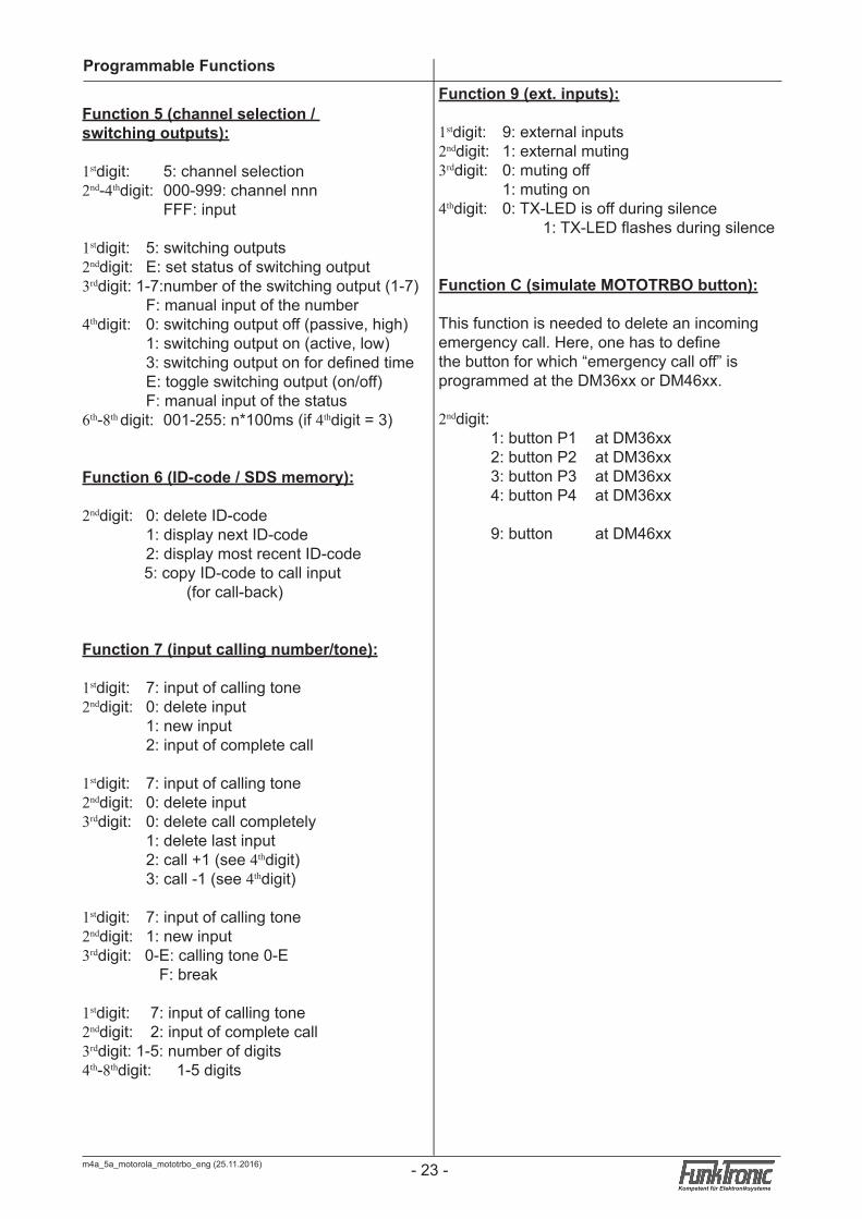
Function 5 (channel selection / switching outputs):
1stdigit: 5: channel selection2nd-4thdigit: 000-999: channel nnn FFF: input
1stdigit: 5: switching outputs2nddigit: E: set status of switching output3rddigit: 1-7:number of the switching output (1-7) F: manual input of the number4thdigit: 0: switching output off (passive, high) 1: switching output on (active, low) 3: switching output on for defined time E: toggle switching output (on/off) F: manual input of the status6th-8th digit: 001-255: n*100ms (if 4thdigit = 3)
Function 6 (ID-code / SDS memory):
2nddigit: 0: delete ID-code 1: display next ID-code 2: display most recent ID-code 5: copy ID-code to call input (for call-back)
Function 7 (input calling number/tone):
1stdigit: 7: input of calling tone2nddigit: 0: delete input 1: new input 2: input of complete call
1stdigit: 7: input of calling tone2nddigit: 0: delete input3rddigit: 0: delete call completely 1: delete last input 2: call +1 (see 4thdigit) 3: call -1 (see 4thdigit)
1stdigit: 7: input of calling tone2nddigit: 1: new input3rddigit: 0-E: calling tone 0-E F: break
1stdigit: 7: input of calling tone2nddigit: 2: input of complete call3rddigit: 1-5: number of digits4th-8thdigit: 1-5 digits
Function 9 (ext. inputs):
1stdigit: 9: external inputs2nddigit: 1: external muting3rddigit: 0: muting off 1: muting on4thdigit: 0: TX-LED is off during silence 1: TX-LED flashes during silence
Function C (simulate MOTOTRBO button):
This function is needed to delete an incoming emergency call. Here, one has to define the button for which “emergency call off” is programmed at the DM36xx or DM46xx.
2nddigit: 1: button P1 at DM36xx 2: button P2 at DM36xx 3: button P3 at DM36xx 4: button P4 at DM36xx
9: button at DM46xx
m4a_5a_motorola_mototrbo_eng (25.11.2016)- 24 -Kompetent für Elektroniksysteme
m4a_5a_motorola_mototrbo_eng (25.11.2016) - 25 -Kompetent für Elektroniksysteme
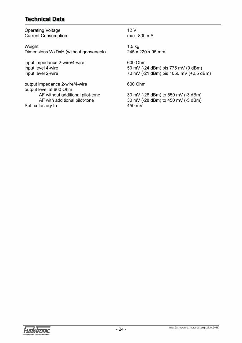
Technical Data
Operating Voltage 12 VCurrent Consumption max. 800 mA
Weight 1,5 kgDimensions WxDxH (without gooseneck) 245 x 220 x 95 mm
input impedance 2-wire/4-wire 600 Ohminput level 4-wire 50 mV (-24 dBm) bis 775 mV (0 dBm)input level 2-wire 70 mV (-21 dBm) bis 1050 mV (+2,5 dBm)
output impedance 2-wire/4-wire 600 Ohmoutput level at 600 Ohm AF without additional pilot-tone 30 mV (-28 dBm) to 550 mV (-3 dBm) AF with additional pilot-tone 30 mV (-28 dBm) to 450 mV (-5 dBm)Set ex factory to 450 mV
m4a_5a_motorola_mototrbo_eng (25.11.2016)- 24 -Kompetent für Elektroniksysteme
m4a_5a_motorola_mototrbo_eng (25.11.2016) - 25 -Kompetent für Elektroniksysteme
Please read the operating instructions carefully before installation and setup.
The relevant regulations must be complied to when working with 230V line voltage, two-wire-lines, four-wire-lines and ISDN-lines. It is also very important to comply to the regulations and safety instructions of working with radio installations.
Please comply to the following safety rules:
- All components may only be mounted and maintained when power is off.
- The modules may only be activated if they are built in a housing and are scoop-proof.
- Devices which are operated with external voltage - especially mains voltage - may only be opened when they have been disconnected from the voltage source or mains.
- All connecting cables of the electronic devices must be checked for damage regularly and must be exchanged if damaged.
- Absolutely comply to the regular inspections required by law according to VDE 0701 and 0702 for line-operated devices.
- Tools must not be used near or directly at concealed or visible power lines and conductor paths and also not at and in devices using external voltage – especially mains voltage - as long as the power supply voltage has not been turned off and all capacitors have been discharged. Electrolytic capacitors can be still charged for a long time after turning off.
- When using components, modules, devices or circuits and equipment the threshold values of voltage, current and power consumption specified in the technical data must absolutely be complied to. Exceeding these threshold values (even if only briefly) can lead to significant damage.
- The devices, components or circuits described in this manual are only adapted for the specified usage. If you are not sure about the purpose of the product, please ask your specialized dealer.
- The installation and setup have to be carried out by professional personnel.
Returning of Old EquipmentAccording to German law concerning electronic devices old devices cannot be disposed off as regular waste. Our devices are classified for commercial use only. According to § 11 of our general terms of payment and delivery, as of November 2005, the purchasers or users are obliged to return old equipment produced by us free of cost. FunkTronic GmbH will dispose of this old equipment at its own expense according to regulations.
Please send old equipment for disposal to: FunkTronic GmbH Breitwiesenstraße 4 36381 Schlüchtern
>>> Important hint: freight forward deliveries cannot be accepted by us.
2 February, 2006
Subject to change, Errors excepted
General Safety Information

m4a_5a_motorola_mototrbo_eng (25.11.2016)- 26 -Kompetent für Elektroniksysteme
Release Notes
Oct-09, 2014 - Translation of German manual dated from Oct-08, 2014
Nov-25, 2016 - Function C (simulate MOTOTRBO button) corrected