Embed Size (px)
Citation preview
1
A Process Modelling Framework for Formal Validation of Panama Canal System Operations
John Johnson Department of Civil Engineering,
University of Maryland, College Park, MD 20742, USA.
Mark A. Austin Institute for Systems Research
University of Maryland College Park, MD 20742
Copyright © 2008 by Institute for Systems Research. Published and used by INCOSE with permission.
Abstract. In this paper we develop a process modeling framework for the evaluation and formal validation of Panama Canal system operations. Component- and architecture-level processes are organized into a three level hierarchy and modeled in LTSA. Safety and progress requirements are formally expressed as processes that can be evaluated through compositional and search processes, respectively.
Introduction
Problem Statement. The Panama Canal is one of the world’s most important waterways. Initially opened for operation in 1914, the canal is now in the midst of a US $5 billon upgrade from industrial- to information-age capability (Panama Canal Upgrade, 2007). From a functional perspective, the new canal system will be capable of servicing a larger number of vessels, handling larger ships than before (i.e., so-called post-Panamax ships) and will even provide for continued operations while sections of the canal system are undergoing maintenance. It is estimated that by 2010, post-Panamax ships will have 50 percent of the world’s capacity for moving containers (Maxing Out, 2007). From a performance perspective, the present-day Panama Canal is typical of many large-scale waterways, where operations (e.g., shipping throughput; avoiding accidents) are limited by an ability to: (1) sense relevant activities and event in the surrounding environment, (2) look ahead and anticipate events, and (3) control system behavior. In an effort to relax, or even remove, these constraints, next-generation waterway systems are incorporating advances in computing, sensing, and communications. Sensors gather data which is fed to computers for advanced processing. The enriched information leads to better decision making which in turn is fed back to automated control systems. Through this process, the aforementioned barriers are overcome, thereby providing the desired results.
The first important consequence of this trend is that over time, present-day reliance on
centralized management of canal operations will be replaced by canal operations that are partially or fully decentralized. From a systems engineering perspective, this means that present-day canal systems that may have only a small number of current behaviors will be replaced by system architectures having many concurrent behaviors. A second consequence is that automation will replace some canal operations currently handled by humans. Design for automation in large-scale system operations is challenging because in addition to making sure system performance is adequate, we also need to validate that the automation system is capable
2
and will do the right thing in the first place. Lessons learned from industry (Jackson 2006; Magee 2006, Sangiovanni-Vincentelli 1996) indicate that there are now many automated engineering systems with complexity approaching the point where validation of design correctness will be impossible without mechanisms for verification are built into the design process itself. These mechanism include (Sangiovanni-Vincentelli 2000):
• Formal Models. We need ways to capture the design representation and it specification in an
unambiguous ``formal language'' that has precise semantics. • Abstraction. Abstraction mechanisms eliminate details that are of no importance when
evaluating system performance and/or checking that a design satisfies a particular property. • Decomposition. Decomposition is the process of breaking a design at a given level of
hierarchy into subsystems and components that can be designed and verified almost independently.
The hypothesis of our work is that these challenges can be kept in check through approaches to design that apply these mechanisms in a disciplined manner. Accordingly, the purposes of this paper are to explain how: (1) Architecture-level models of canal behavior can be systematically assembled from component-level behaviors, (2) Design requirements for safety and liveliness can be expressed formally and finite state processes, and (3) Safety validation can be accomplished through composition of finite state process models for canal behaviors and requirements. These principles are illustrated through simplified process models of Panama Canal behavior constructed in the labeled transition system analyzer (LTSA 2007).
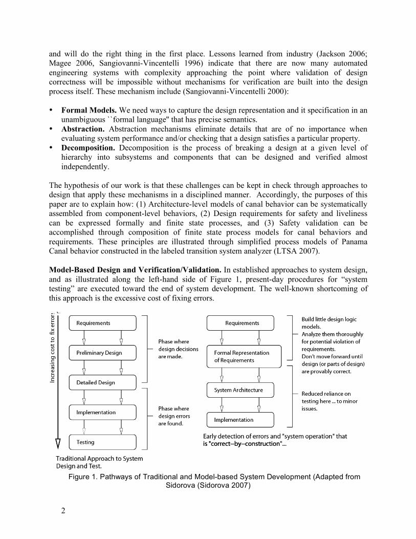
Model-Based Design and Verification/Validation. In established approaches to system design, and as illustrated along the left-hand side of Figure 1, present-day procedures for “system testing” are executed toward the end of system development. The well-known shortcoming of this approach is the excessive cost of fixing errors.
Implementation
System Architecture
Formal Representationof Requirements
Requirements
Testing
Implementation
Detailed Design
Preliminary Design
Requirements
Incre
asi
ng c
ost
toix
err
or
Phase wheredesign errorsare found.
are made.design decisionsPhase where
issues.testing here ... to minorReduced reliance on
Build little design logicmodels.Analyze them thoroughlyfor potential violation ofrequirements.Don’t move forward untildesign (or parts of design)are provably correct.
Early detection of errors and "system operation" that
Design and Test.Traditional Approach to System
Figure 1. Pathways of Traditional and Model-based System Development (Adapted from
Sidorova (Sidorova 2007)
3
Emerging approaches to system design (Magee 2006, Sidorova 2007, Uchitel 2004) are based upon formal methods and selective use of design abstractions. The new approach benefits system design in two ways: (1) Concepts and notations from mathematics can provide methodological assistance, facilitating the communication of ideas and the thinking process, and (2) Formal methods allow us to calculate some properties of a design. by building design logic into requirements and using formal models for synthesis of architecture-level representations. As illustrated along the right-hand side of Figure 1, the goal is to move design processes forward to the point where early detection of errors is possible and system operations are correct-by-construction (Sidorova 2007).
Process Modeling and Validation with LTSA The labeled transition system analyzer (LTSA) is a tool for validating communication and sequencing among entities in systems containing concurrent behaviors (LTSA 2007). In LTSA, processes correspond to sequences of actions. Spatial and temporal design concerns are not captured in LTSA (i.e., they are abstracted from modeling consideration). The textual representation is the finite state process (FSP) language. Labeled transition systems (LTSs) are the graphical representation. From Requirements to Behavior with LTSA. The transformation from requirements to high-level design occurs with the following activities: (1) identify main events, actions and interactions, (2) identify main processes, (3) identify and define properties of interest, and (4) structure processes into an architecture. Each canal component or subsystem will have behavior that can be defined by a finite state machine. Therefore, architecture-level models of behavior will be viewed as a network of interacting finite state machine processes. A top-down specification of required behavior for components can be specified through the use of visual modeling languages such as UML. Models of architecture-level behavior (details given below) are synthesized through a bottom-up composition of component-level behaviors. Specification of Component- and Architecture-Level Behavior. Process modeling of component-level behavior can be specified directly through FSP code. If concurrent behaviors have common elements, then there will be an interleaving of behaviors linked at common actions. Models of architecture-level behavior are obtained through the parallel composition of concurrent processes at the component level. Given two labeled transition systems (LTSs), let’s say P1 and P2 we denote the parallel composition P1 || P2 as the LTS that models their joint behavior. By extension, the architectural-level behavior model is defined by the product: P1 || P2 || ….. || PN, where Pi is the finite state model for the i-th component among N interacting components. Joint behavior is the result of all LTSs executing asynchronously, but synchronizing on all shared message labels. At the component level, the nodes of a labeled transition system represent states the component can be in. At the architecture level, labeled transition system nodes represent system-level states, which, in turn, correspond to specific combinations of component-level states. Transitions are labeled with messages that components send to each other. Validation of Requirements. The properties required of the system are also modeled as state
4
machines. LTSA mechanically checks that the specification of a concurrent system satisfies the properties required of its behavior. A good system: (1) exhibits safety and liveliness, and (2) avoids deadlocks. A safety property asserts that nothing bad will happen during the system execution. A liveliness property asserts that something good eventually happens (e.g., suppose that ships are approaching the Panama Canal. Liveliness would assert that, eventually, all of them will be able to pass through the passageway safely). A system state is deadlocked when there are no eligible actions that a system can perform. Formal model checking procedures make sure that the architecture-level design: (1) does what it is supposed to do; (2) prevents certain behaviors from occurring; and (3) does not support un-intended behaviors. If any one of these aspects is violated, then we have a gap between the intended system and the actual system design. The resulting high-level design is much more abstract than a detailed software/hardware implementation. But it captures the key patterns of interaction and can be formally analyzed for safety and liveliness properties. A detailed software/hardware implementation and optimization follows design.
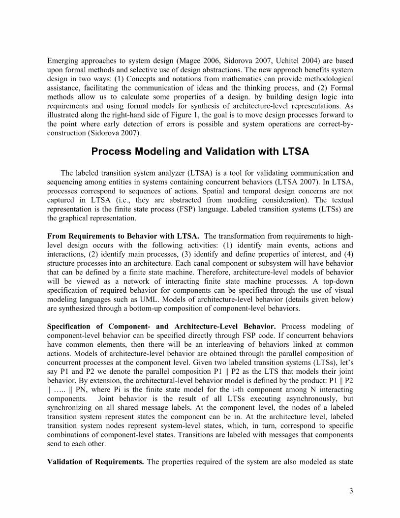
Building the Panama Canal Process Model The Panama Canal. The Panama Canal is an 80 kilometer passageway that joins the Atlantic and Pacific Oceans. See Figure 2.
Figure 2. Plan and Elevation View of the Panama Canal.
A ship passing through the canal will ascend through a set of locks, traverse Lake Gatun, and then descend through the lock system on the other side. The lock systems consist of a set of lock compartments having entrance and exit gates.
5
The locks function as water lifts, raising ships from sea level to the elevation of Lake Gatun (26 meters above sea level). The lock chambers are 33.53 meters wide and 304.8 meters long. The maximum dimensions of a ship that can transit the canal are: 32.3 meters in the beam, 12 meters draft, and 294 meters long. The water used to raise and lower the vessels in each set of locks comes from Lake Gatun by gravity.
Basic Ship Behavior. As a ship approaches the first chamber, valves below the compartment are released and the water level adjusts to that outside of the canal. The gates then open and the ship moves into the first chamber. After the gates lock, valves of the first and second chamber are opened to allow the water level of the first chamber to rise and match the second chamber. The gates open for a second time, allowing the ship to move into the second chamber. This repetitive process continues until the ship reaches the Lake Gatun. The ship traverses the lake and then descends through the exit lock system. The basic ship behavior is identical for crossings Pacific to Atlantic and Atlantic to Pacific.
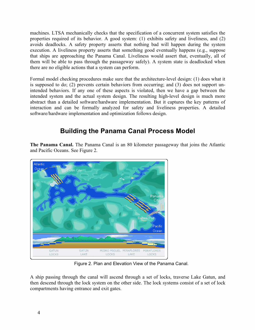
Component-Level Processes Figures 3 and 4 show elevation view of a double lock system architecture, the component-level processes, and labeled transition system (LTS) representations for sequences of actions representing basic component level behavior.
Figure 3. Elevation View of Lock System Components, Component- and Subsystem-Level
Processes.
The lock system architecture is an assemblage of Gate, Pump, and Ship processes. Gates can open and close, and Pumps can adjust the water level ``up’’ and ``down’’ (i.e., release). In the present-day canal, adjustments to water level are achieved through gravity feed from lake Gatun. The modified Panama Canal will rely on mechanical pumps and water saving basins. In LTSA, these actions are specified in FSP by writing:
6
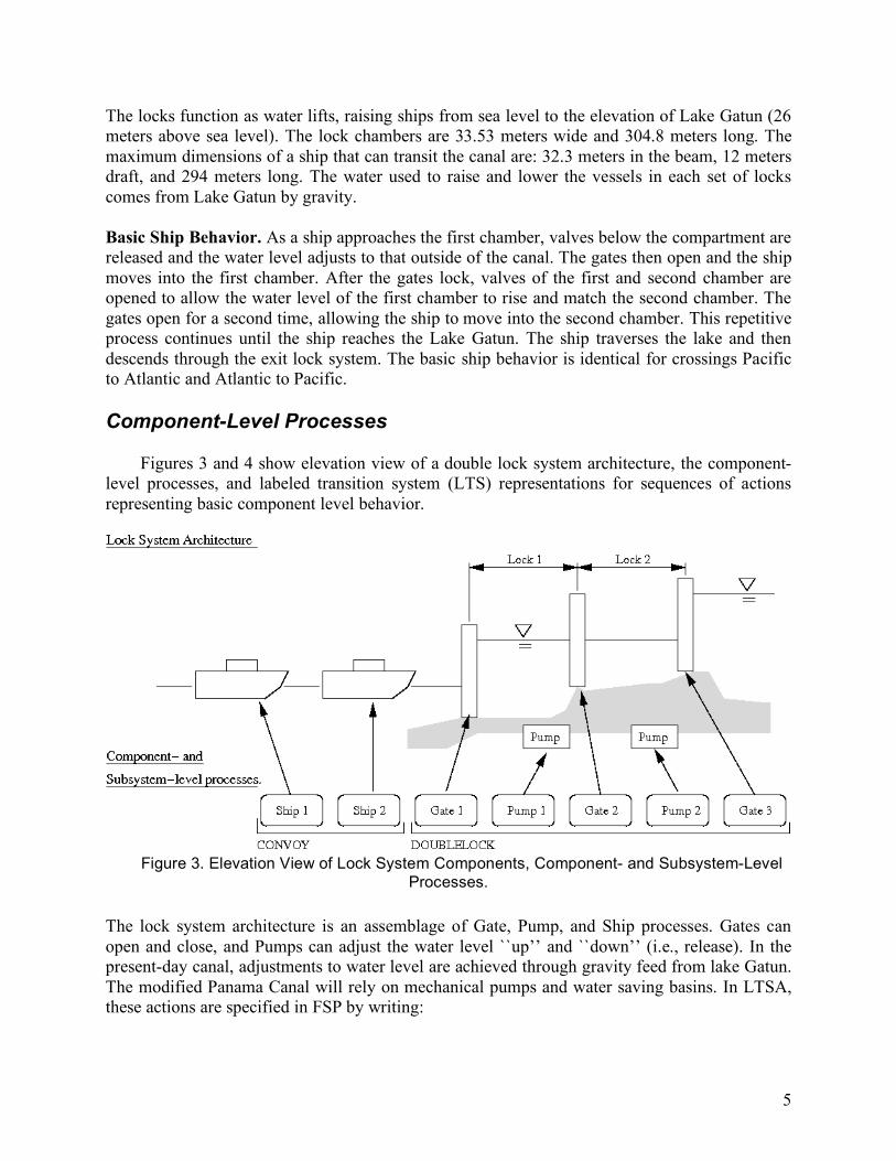
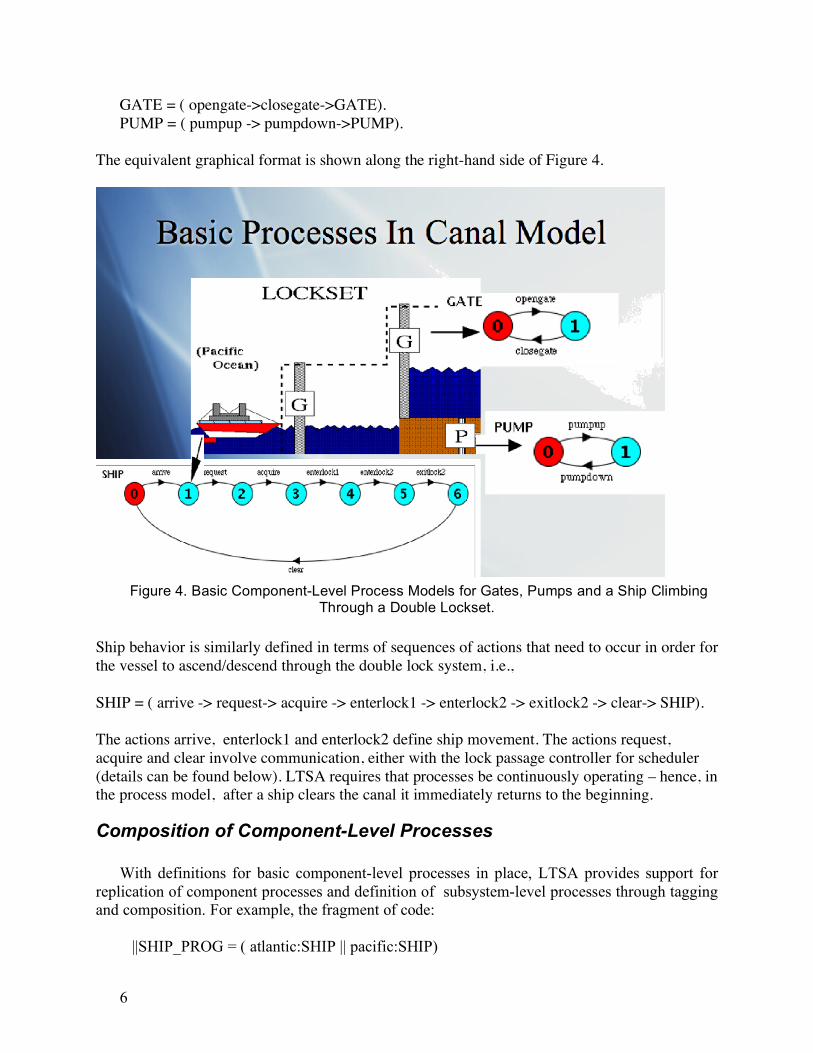
GATE = ( opengate->closegate->GATE).
PUMP = ( pumpup -> pumpdown->PUMP).
The equivalent graphical format is shown along the right-hand side of Figure 4.
Figure 4. Basic Component-Level Process Models for Gates, Pumps and a Ship Climbing
Through a Double Lockset.
Ship behavior is similarly defined in terms of sequences of actions that need to occur in order for
the vessel to ascend/descend through the double lock system, i.e.,
SHIP = ( arrive -> request-> acquire -> enterlock1 -> enterlock2 -> exitlock2 -> clear-> SHIP).
The actions arrive, enterlock1 and enterlock2 define ship movement. The actions request,
acquire and clear involve communication, either with the lock passage controller for scheduler
(details can be found below). LTSA requires that processes be continuously operating – hence, in
the process model, after a ship clears the canal it immediately returns to the beginning.
Composition of Component-Level Processes
With definitions for basic component-level processes in place, LTSA provides support for
replication of component processes and definition of subsystem-level processes through tagging and composition. For example, the fragment of code:
||SHIP_PROG = ( atlantic:SHIP || pacific:SHIP)
7
||CONVOY = ([1..2]:SHIP_PROG).
creates tags for ships on the Atlantic and Pacific sides of the canal, and then a convoy of ships on each side. At this point, the individual ships have completely independent behavior. Additional program structure can be enforced by creating queue processes and constraining the behavior to follow a first-in/first-out policy. Similarly, unconstrained behavior of the lock system components in achieve through composition of the pump and gate processes, e.g., ||DOUBLEGATE = ( low:PUMP || high:PUMP || low:GATE || middle:GATE || high:GATE).
creates a lockset with three gates (tagged, low, middle, and high) and two pumps (tagged low and high). The DOUBLEGATE process model has 32 states representing all possible permutation of pump and gates states. It is important to note that our use of tagged names simply relate processes to their position in the lockset system and are decoupled from spatial concerns (e.g., which lockset is on the West or East side of the Panama Canal). Hence, it is possible to systematically assemble a complete lockset process model, which in turn can act as a template or module for assembly of behavior for arbitrary canal configurations.
High-Level Canal Operations
By themselves, the pumps, gates and ships are independent processes that accomplish
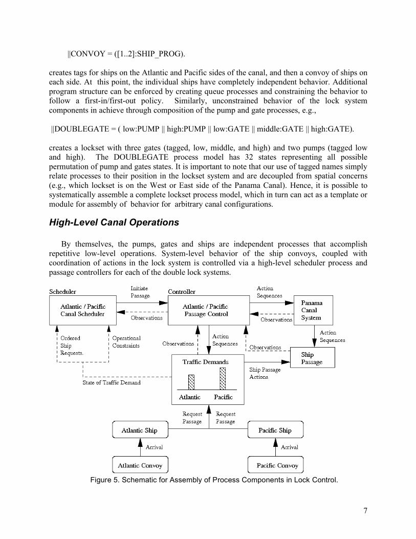
repetitive low-level operations. System-level behavior of the ship convoys, coupled with coordination of actions in the lock system is controlled via a high-level scheduler process and passage controllers for each of the double lock systems.
Figure 5. Schematic for Assembly of Process Components in Lock Control.
8
Figure 5 shows the essential details of communication among the scheduler, passage control, canal system (pumps and gates), and ship passage processes. When a ship ‘’arrives’’ at either the Atlantic or Pacific canal entrances, it request permission to enter the first lock system. If the lock system is currently occupied then the scheduler will direct the ship to join a queue. Eventually the ship will acquire access to the lock set, and be guided through the ascend/descend operations by the passage controller process (i.e., enterlock1, enterlock2, exitlock2, clear). Constraints on passage control ensure that the sequencing of ship actions is consistent with physical constraints. For example, if a ship enters the Panama Canal from the Atlantic side, then it needs to completely traverse the Atlantic-side lockset for before entering and descending through the Pacific-side lockset. These constraints can be enforced through sequences of actions that define entry and exit from specific locksets, e.g., the process
EASTNOPASSLOCK = (atlantic.arrive -> atlantic.clear -> pacific.arrive -> pacific.clear -> EASTNOPASSLOCK).
preserves order of operations for a ship traversing the canal, East to West.
Full Canal Model
The full canal model is defined through a system-level composition of Pacific- and Atlantic-side systems together with the process model for ship convoy behavior. In turn, the Pacific- and Atlantic-side processes are a composition of DOUBLEGATE, PASSSAGECONTROL and SCHEDULER processes. Joint behaviors in the full canal model correspond to sequenced actions/interactions between lower-level processes – these actions reduce the size of the overall model. Still, models are very large, often exceeding 140,000 different states (i.e., distinct combinations of subsystem and component-level states). With small process models (e.g., containing less than 20-30 states), one can visualize communication between the states in LTSA. Since this approach is intractable for analysis of full canal systems, we must resort to mathematics to formally validate properties of the full canal process model.
Formal Validation of Panama Canal Operations In our approach to process modeling and formal validation, requirements are written as
properties that can be formally evaluated with respect to the component- and architecture-level models. A property is an attribute of a process that is true for every possible execution of that process. Properties of interest for current processes fall into two categories: safety and liveliness. We also need to check that the proposed system will not enter a deadlock state – that is, a state for which there is no exit (or outgoing transition) , and hence the system becomes blocked and cannot make further progress.
9
Safety of Canal Operations
A safety property asserts that nothing bad happens during the canal operation. For Panama
Canal operations we need to ensure that at all times: (1) The canal scheduler will not assign more than one ship to a lock; (2) Ships acquire a lock before clearing it; (3) West-bound ships will clear the Atlantic lockset before the Pacific lockset (and vice versa for East-bound ships); and (4) Floods will be prevents by ensuring that a gate will not open before water levels on both side of the gate are equalized.
Safety properties are specified in FSP by property processes. Safety checks are compositional
in the sense that if there is no violation at a subsystem level, then there cannot be a violation when that subsystem is composed with other subsystems. For example, the abbreviated fragment of code:
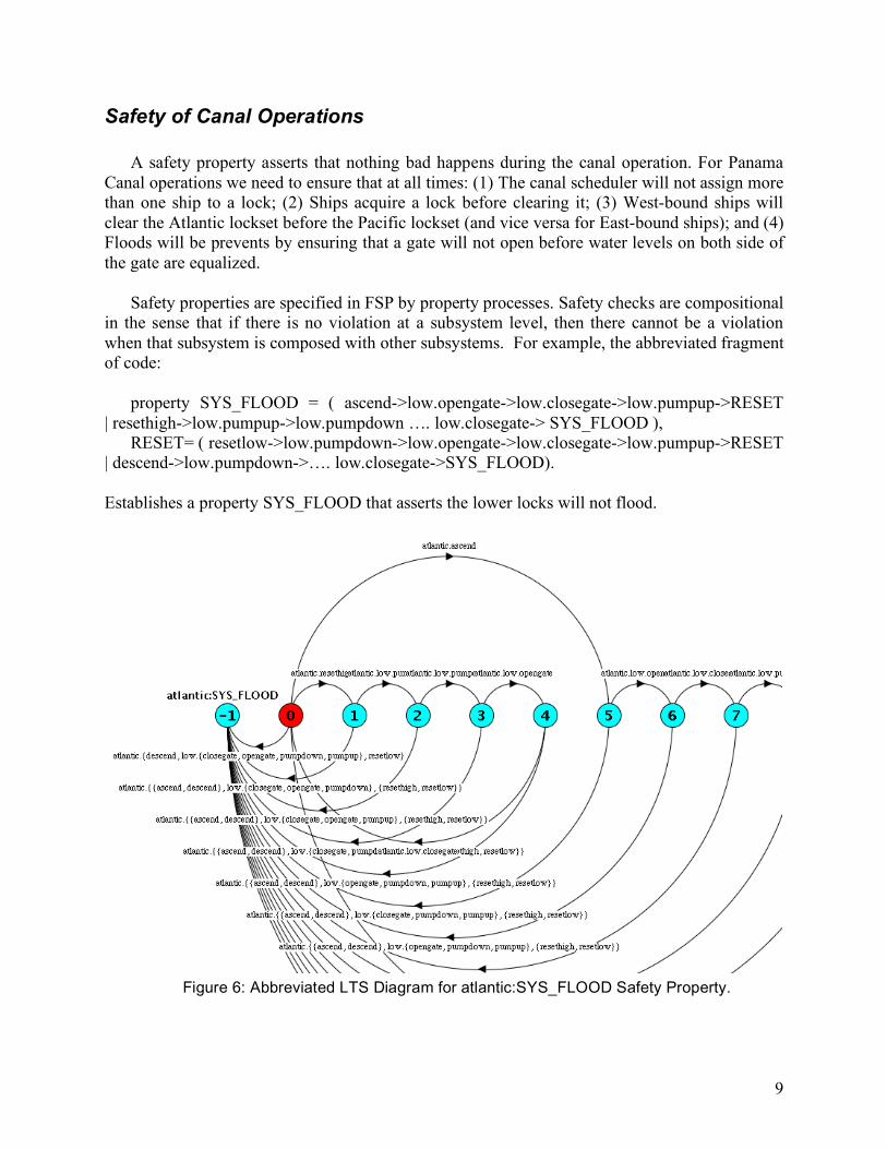
property SYS_FLOOD = ( ascend->low.opengate->low.closegate->low.pumpup->RESET
| resethigh->low.pumpup->low.pumpdown …. low.closegate-> SYS_FLOOD ), RESET= ( resetlow->low.pumpdown->low.opengate->low.closegate->low.pumpup->RESET
| descend->low.pumpdown->…. low.closegate->SYS_FLOOD).
Establishes a property SYS_FLOOD that asserts the lower locks will not flood.
Figure 6: Abbreviated LTS Diagram for atlantic:SYS_FLOOD Safety Property.
10
By default, and as illustrated in Figure 6, the LTSA compiler will automatically generate transitions to the error state. In total the atlantic:SYS_FLOOD property process contains 17 states, 16 for the process specification, and one for the error state. Two outcomes are possible when the flood property processes are composed with the system specification, i.e., ||FULLCANAL_TEST = (FULLCANAL || pacific:SYS_FLOOD || atlantic:SYS_FLOOD). If the combined canal–property process does not contain an error, then the FULLCANAL_TEST
specification will remain unchanged. If on the other hand, there is an error in the architecture-level design, indicating the possibility of an accidental flood occurring, then this will show up through the presence of an error state in FULLCANAL_TEST.
Liveliness of Canal Operations
A liveliness property asserts that something good eventually happens. For the Panama Canal
application we need to ensure that all ships will eventually clear the system. Accordingly the statement pair:
progress EASTPASS = {east.[1..2].atlantic.clear} progress WESTPASS = {west.[1..2].pacific.clear} asserts that all east-bound ships will eventually clear the Atlantic lockset and, conversely, all
west-bound ships will eventually clear the Pacific lockset. It is important to note that unlike safety properties, liveliness (or progress) checks are not compositional. Instead, progress analysis involves the systematic construction of terminal sets. A progress violation occurs if one or more terminal sets does not contain at least one of the terminal set actions (i.e., east[1].atlantic.clear or east[2].atlantic.clear for east-bound ships).
Conclusions and Future Work The essential details of a process modeling framework for the formal evaluation and
validation of Panama Canal System operations has been presented in this paper. The importance of this work stems from the critical role that the Panama Canal plays in global shipping operations. Motivation for this work stems from the difficulty engineers have in evaluating and validating designs where behavior is defined by decentralized operations (many concurrent behaviors), yet automation (sensors, control, computer software) is needed for the implementation of correct working operations. The enablers for our work are finite state processes and the labeled transition analyzer (LTSA). LTSA has its roots in the analysis of computer operating system processes. Yet, as we have shown in this paper, fundamental properties for design can be easily reinterpreted and placed in a canal design setting.
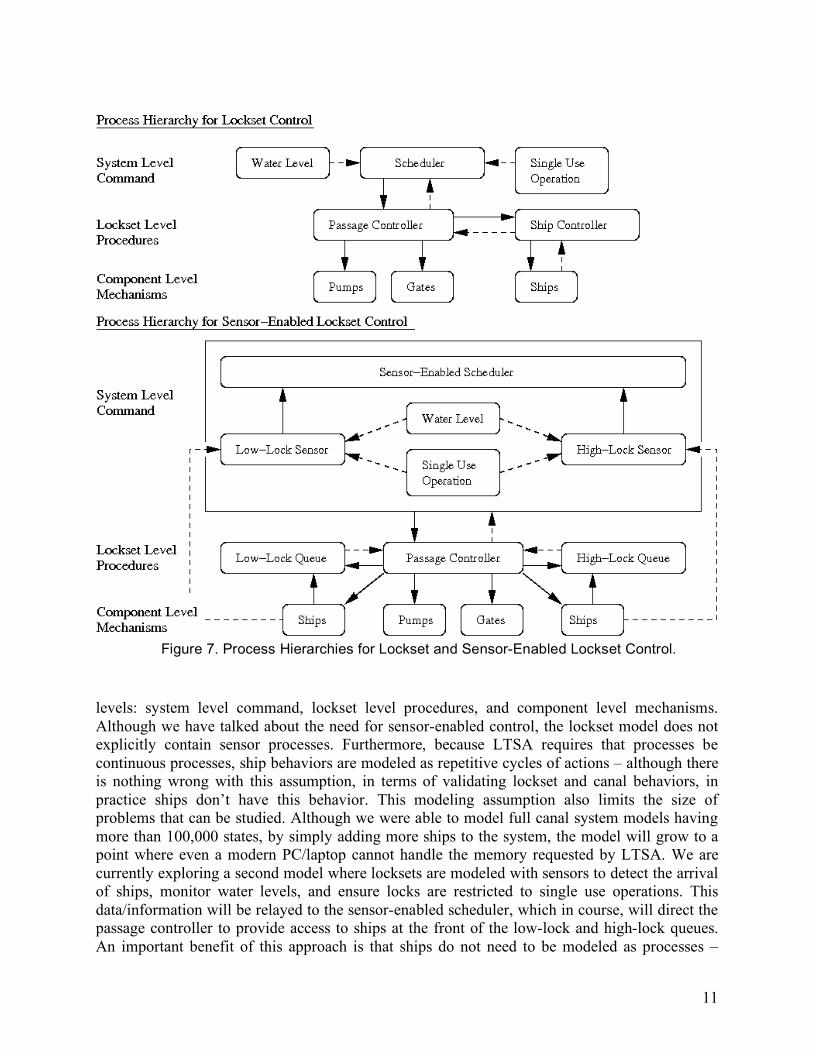
Figure 7 shows process hierarchies for lockset and sensor-enabled lockset control. In this paper we have restricted discussion to lockset control (i.e., we have described scheduler, passage control, ship control, ship, gate and pump processes). Processes have been organized into three
11
Figure 7. Process Hierarchies for Lockset and Sensor-Enabled Lockset Control.
levels: system level command, lockset level procedures, and component level mechanisms. Although we have talked about the need for sensor-enabled control, the lockset model does not explicitly contain sensor processes. Furthermore, because LTSA requires that processes be continuous processes, ship behaviors are modeled as repetitive cycles of actions – although there is nothing wrong with this assumption, in terms of validating lockset and canal behaviors, in practice ships don’t have this behavior. This modeling assumption also limits the size of problems that can be studied. Although we were able to model full canal system models having more than 100,000 states, by simply adding more ships to the system, the model will grow to a point where even a modern PC/laptop cannot handle the memory requested by LTSA. We are currently exploring a second model where locksets are modeled with sensors to detect the arrival of ships, monitor water levels, and ensure locks are restricted to single use operations. This data/information will be relayed to the sensor-enabled scheduler, which in course, will direct the passage controller to provide access to ships at the front of the low-lock and high-lock queues. An important benefit of this approach is that ships do not need to be modeled as processes –
12
instead, they are simply viewed as objects that are directed to pass through the canal system. Results of this work along with complete details of the LTSA analyses will be released in an ISR Technical Report (Johnson and Austin, 2007). Future work will focus on development of methods to keep problem sizes in check through: (1) judicious use of abstractions, and (2) layered organization and evaluation of property models. Acknowledgement. This work reported in this paper was supported, in part, by a summer grant to the first author from the NSF Research Experiences for Undergraduates (REU) Program.
References
Jackson, D., Dependable Software by Design. Scientific American, 294(6), June 2006. Johnson J., and Austin M., Mechanical Verification of Panama Canal System Operations with
LTSA, ISR Technical Report 2007-XX, Institute for Systems Research, University of Maryland, College Park, MD 20742, December 2007. (to be released).
Labeled Transition System Analyzer (LTSA) Home Page. See:
http://www.doc.ic.ac.uk/jnm/ltsa/LTSA.html. Accessed, November 2007. Magee J.L., and Kramer J., Concurrency: State Modelsand Java Programs (2nd Edition), John
Wiley and Sons, New York, 2006. Maxing Out, Economist 382, Academic Search Premier, Volume 71, 2007. Sangiovanni-Vincentelli A. Automotive Electronics: Trends and Challenges. In Presented at
Convergence 2000, Detroit, MI, October 2000. Sangiovanni-Vincentelli A., McGeer P.C., Saldanha A. Verification of Electronic Systems : A
Tutorial. In Proceedings of the 33rd Desgin Automation Conference, Las Vegas, 1996. Sidororva N., Lecture Notes on Process Modeling, Graduate Course, Department of Mathematics
and Computer Science, Eindhoven University, Netherlands, 2007. The Panama Canal’s Ultimate Upgrade, Popular Mechanics, Volume 184, 2007, pp. 56-61.
Academic Search Premier. EBSCO. Uchitel S., Kramer J., and Magee J. Incremental Elaboration of Scenario-Based Specifications
and Behavior using Implied Scenarios. ACM Transactions on Software Engineering and
Methodology, 13(1):37–85, January 2004.
Biography John Johnson is an undergraduate student in the Department of Civil and Environmental
Engineering at the University of Maryland, College Park. Mark Austin is an Associate Professor in the Department of Civil and Environmental
13
Engineering, University of Maryland, College Park. He currently holds an affiliate appointment with the Institute for Systems Research. During the past ten years, Mark has taught extensively in the Master of Science in Systems Engineering (MSSE) program, and conducted short courses in Systems Engineering at US companies, and in Europe and South America. He has a Bachelors degree in Civil Engineering from the University of Canterbury, New Zealand, and Masters and Ph.D. degrees in Civil Engineering from UC Berkeley.