Embed Size (px)
Citation preview
16
In the past I have rewound series field coils using a variable speed battery drill held in a vice. These fields have relatively few turns and a largish wire size but this radio used a shunt coil with lots of turns of 38-gauge wire. Obviously for it and the inter-stage transformer something better than the drill in the vice was needed.
Basic RequirementsThe field coil in question weighed three pounds and being as it used a bobbin without cheeks this was almost all copper wire. It and the feed coil, being so heavy, were going to need spindles supported at both ends. I knew from experience, with the drill in the vice, how much better it would be to have a foot pedal for start and stop and control of speed. Later I was to find that some sort of traverse, for the feed wire, made for a much more uniform winding. For the field coil I wouldn’t really need a turns counter, just fill a new bobbin, but for the inter-stage transformer this would not be the case. Finally, being as I wouldn’t use it all that much I wanted it to be low cost with parts mainly from the junk box.
ConstructionI’ll keep this description relatively simple; in the event that anyone should want to make a similar machine then the pictures should tell most of the story. However, I have given some dimensions of my effort, which should assist another constructor. Fortunately I had variable speed battery drill with a well worn chuck and a tired battery. The chuck no longer gripped drills sufficiently for high torque jobs but was fine for coil winding as not a lot of torque is needed. The battery would hold charge long enough and I could substitute batteries from other drills (the battery holder is less specific than an actual drill). Once stripped down the chuck, gearbox and motor assembly were mounted as shown in the pictures. The gearbox and motor do come apart so both need to be individually clamped. The clamps were
made from scraps of plywood having a hole cut through them with a hole-saw. Once cut in half, across the hole, I put a locating key (a ‘lost head’ nail with its head proud) which fits into slots in both items. Then long thin wood screws were used to tighten the clamps. In the case of the motor clamp this is also screwed to the side panel. The gearbox was best set for screw driving as it gives a much smoother start although the maximum speed is less. In practice, most drills in this mode are specified at 400 RPM, which is adequate. I included a cover over the motor end to protect it upon entry and exit from the loft where it will live between jobs. As can be seen the trigger and speed control are built into a simple housing, with the control best operated without a slipper! The battery simply drops through the hole with the rewired connector being attached as this is done. The drill takes three to four amps so I used a large wire gauge between it and the foot control. The only heavy wire I had was some spare cooker cable so I stripped the red and black wires from that. At first the items were hard wired but this got inconvenient so I included a plug and socket (US line types). The traverse for the wire feed is the piece of chrome plated tube, scrap from an old shower installation. It’s simple and how I use it is described later. Well, you didn’t really expect me to come up with a gear driven backwards and forwards mechanism as used on Pro. machines did you. The frame was made from15 mm thick plywood and dimensions (which would vary with the drill used) are: overall length 15.5, depth 10.5, height 9.5 inches excluding motor cover and turns counter. The feed wire spindle is set back from the front by 2.5 inches and is 2.5 inches up from the inside base. The traverse tube is 2 inches back from the feed wire spindle and 5.5 inches up from the inside base. The motor spindle is 3 inches in from the rear and 6.25 inches up from the inside base. The centre holes, for the feed and take up spindles, were drilled with the side panels clamped together of course. The
Making a Coil Winder (mostly from the junk box) part 1by Gary Tempest Improvements, modifications and winding an interstage transformer in part 2 (to follow)
Why make a coil winder? Well with old radios eventually you come up against open circuit components and for the one I was restoring this was the case. It had an open speaker field coil and push-pull inter-stage transformer. Yes! There are ways around re-winding such as substitution of permanent magnet speakers and other transformers. But this is really fixing a radio up and isn’t restoration. It’s so much more satisfying to rewind and put the set back as it was originally.
17
traverse tube is fixed in place by cutting two plywood discs, that fit the inside of the tube, and screwing them to the side panels. Initially I only had a hole in the left-hand side piece for the motor spindle and therefore made this side relatively quickly detachable. It is held to the bottom with furniture blocks having a machine screw. However, in practice when trying to fit the bobbin for the new wound coil it turned out to be very awkward. The solution was to slot the hole and fit an easily removed ‘bearing cap’. All bearing holes were lubricated with lithium grease. The feed and motor spindles were cut from easily obtainable 10 mm studding. I found out that the feed and new coil bobbin need to be securely fixed so I used a wing and a full nut locking one against the other. I did the same for the end of the removable spindle for the feed bobbin and locked these up hard before starting. It’s surprising how things become loose with the inevitable vibration. Slippage on the wound coil only gives a few more indicated turns, a jam on the feed means the wire breaks!
Turns CounterIntroductionI looked around for some time for a rotary counter (tape recorder etc) but did not find anything. Anyway they may have been difficult to drive requiring greater mechanical input than electronic. There are electro-magnetic counters but they are relatively expensive and of course they still need some sort of switch, operated by the shaft upon which the coil is mounted, to provide input. So I turned to 4000 Series Cmos, which is now obsolete although fortunately still readily available. It’s excellent for low-speed applications with good noise immunity. I was lucky enough to work with it (and most other logic families) but it’s now getting on for a couple of decades since I did so. I enjoyed my trip down memory lane whilst designing this useful and inexpensive circuit. It can be built for a few pounds but I had most of the components anyway.
The CircuitIf you have done much work with Cmos logic then this circuit will be simple and you will rapidly move on. If not then I expect it will look daunting, but maybe with some explanation all will become clear. This 4000 series of Cmos (Complimentary Metal Oxide Semiconductor) uses p-type and n-type Mos Fets to achieve its logic functions. When looking at the schematic the first thing to appreciate is that I have only drawn one sample counter output and its associated buffer to LED 5. All the rest are repetitions and given in the ‘running out’ lists below. This is much easier to do than a full drawing and how we convert that information for wiring anyway. The counter is two 4024, 7 stage ripple counters in cascade. The counter outputs are buffered and inverted (3 off 4049 devices) to light LEDs for the output display. The counters work in binary and so a little arithmetic addition (or a scientific calculator) is needed to convert the LED display into decimal for the number of turns.
The decimal values for each LED is given on the label that is glued below the display. So as an example, say LED’s 8, 5, 4, 2 and 1 are lit then just add 128, 16, 8, 2 and 1 to give 155 turns. Alternatively, enter the binary number into a scientific calculator that will do the conversion. You put in 10011101, with unlit LED’s counting as 0, and up comes155. Unlit LED’s, of higher order than the last one lit, don’t count as they wouldn’t if the display was in decimal. It has a maximum count of twice the last LED minus one, which equals 16383. If you go ‘round the clock’ its simple to make a note (mental if you trust it!) and just add this to the total. This may seem cumbersome but I was used to counting in binary and it is something you quickly get the hang of. For an occasional use coil winder it is good enough. Another way to use it is to work out what LED’s will be lit for the number of turns needed first. Then simply mark this on the label with a soft pencil that can be rubbed off later.
Motor and gearbox mounting Gearbox location
Gearbox clamp Motor clamp

18 1818
It’s easy to design a counter to display decimal but it needs a lot more logic devices. To start with decade counters (cascaded), for each digit, followed by decoders for 7 segment displays. Apart from cost the greatest thing against it is the increased wiring complexity as this was going to be hand wired on IC Vero-board (which is not getting any easier!). So I was sticking with a KISS design (KISS equals ‘Keep it Simple Stupid’). It’s easy to dream up additional functionality and complexity until you come to wiring and then you wish you hadn’t. Of course it’s a different matter if you have a draughtsman and a model shop standing by to make you a printed circuit board. My wife, who is into ‘high end’ sewing machines, said: “Can you pre-set the number of turns and go away and leave it to switch off when it’s finished”. “Ugh! No it won’t do that” but I had to smile. A friend asked could it count backwards if you need to take off turns following a mistake. No! It won’t do that either as that would mean Up/Down counters rather than simple ripple ones. These counters are more complex needing up and down clocks and controlling logic. The result of this is that you get less bits per device so two devices become four plus the extra control circuitry. Back to the circuit. The only slightly tricky part was the ‘slotted switch’ to give one input per revolution of the motor and coil spindle. This uses an Infra-Red transmitter and receiver (obtainable from Maplin at the time of writing) with the beam mostly cut off between them by the spindle mounted ‘chopper’ disc. This has a hole drilled in it that allows a pulse of IR once per rotation. I reckoned, from experience, that I would need a Schimdt trigger circuit to de-bounce the receiver output. Upon initial experimentation I decided that I could do without it but I should have been guided by the past. The edges that had looked quite clean on the ‘scope’ certainly weren’t in practice resulting in multiple counts. So in went the Schimdt and this did as expected to give correct operation. Schimdt trigger circuits were around in valve days and were made using ‘long tailed pairs’ with some positive feedback. With suitable bias their output would switch at a certain input voltage for a rising edge. However, in the opposite direction, when the input was falling, they would not switch back until the level was several volts lower than before. So ragged input edges, where the voltage jitters about, are converted to unambiguous output by this hysteresis window.
The 4093 Schimdt device used here has four, two–input inverting AND gates. But, if the two inputs of one gate (the other gates are unused) are strapped together then it becomes a simple logic inverter. The IR receiver when cut off has a high output going low when the hole in the disc passes by. This negative edge is inverted twice (IC 6 and IC 5) advancing the counter on each still negative going edge. The counters are reset to zero by a positive going pulse from the “Reset” switch. In actuality I just placed a couple of pins adjacent to each other on the circuit board for easy shorting. The BC107 transistor provides an alternative test input for the counter board. A low frequency audio generator can be used to verify correct counting action. The 1.5 nF capacitor across it is just an RF filter, for the input wire of the ‘chopper’ circuit, that I put in before the ‘cure all’ Schimdt trigger circuit. It may be unnecessary now but it will do no harm. As the crude EMC tests (see below) were made with it I’m reluctant to take it out. I wasn’t anticipating power cuts for the bench supply I was going to use, but I do have an Earth Leakage Trip and it’s easy to unplug the wrong thing so battery backup seemed good insurance. A PP3 and a couple of changeover diodes provide this. The IR devices were not as the sensitive as I expected. The diode needs a lot of current (40 mA) to achieve good bottoming of the receiver (a transistor with an open base) and this was with only about 3 to 4 mm gap between them. The data sheet quotes a maximum continuous current of 100 mA with up to 1A being allowed, with pulse operation, for applications needing greater distances.
EMCWhich stands for Electro-Magnetic-Compatibility, which I’m sure we are all aware of. Basically it means my kit won’t interfere with yours and yours won’t affect mine, even if it is a DC to blue light generator, because mines such a bloody good piece of design. No one who has been there would be so gung-ho of course. Before the 60’s not much was known or taken into account by many designers for it. Since then a whole branch of electronics has developed around it. My first initiation was back in those ignorant days and an embarrassing incident that was
Foot switch without battery Foot switch with battery
Coil winder left side Turns counter Turns counter circuit

19
22K1.5 nF
1.5 nF0.1
PP39V
0.1
Ic 34049
Ic 1 4024Reset
BC107
Test
Ir TxCH10L
Ir RxCH11M
+10V
0V
Ic 5
9 10
CoCa
An Em
Ic 2 4024
Led 1 to Led 14
IC1 1 2 3 (Q7) 4 (Q6) 5 (Q5) 6 (Q4) 7 8 9 (Q3) 10 11 (Q2) 12 (Q1) 13 14
to IR Rx to IC2/ 2 & Reset to IC2/ 1 & IC5/ 3 to IC3/ 14 to IC3/ 11 to IC3/ 9 to 0V n/c to IC3/ 7 n/c IC3/ 5 IC 3/ 3 n/c to +V
IC2 1 2 3 (Q7) 4 (Q6) 5 (Q5) 6 (Q4) 7 8 9 (Q3) 10 11 (Q2) 12 (Q1) 13 14
done done to IC 5/ 5 to IC 4/ 14 to IC 4/ 11 to IC 4/ 9 to 0V n/c to IC 4/ 7 n/c to IC 4/ 5 to IC 4/ 3 n/c to +V
IC3 1 2 3 4 5 6 7 8 9 10 11 12 13 14 15 16
to +V to Led 1 done to Led 2 done to Led 3 done to 0V done Led 4 done to Led 5 n/c done to Led 6 n/c
IC4 1 2 3 4 5 6 7 8 9 10 11 12 13 14 15 16
to +V to Led 8 done to Led 9 done to Led 10 done to 0V done Led 11 done to Led 12 n/c done to Led 13 n/c
IC5 1 2 3 4 5 6 7 8 9 10 11 12 13 14 15 16
to +V to Led 7 done to Led 14 done n/c to 0V to 0V to Ir Rx to 1C 1/ 1 to 0V n/c n/c to 0V n/c n/c
IC6 1 2 3 5,6,7,8,9,12 &13 4,10,11 14
as circuit as circuit as circuit 0V n/c +V
Note:1K8 Ohmfor each Led
Coil Winder Counter Drn: GNT 27/02/07
Ic 44049
Ic 54049
68K’s
220 100K
100K
1N40
0*
1N400*
+V Nc Q1 Q2 Nc Q3 Nc
I/P R Q7 Q6 Q5 Q4 -V
+V Nc Q1 Q2 Nc Q3 Nc
I/P R Q7 Q6 Q5 Q4 -V
IC 4 & 54049
Ic 640931
2 3
81632641282561024
20488192
Coil winder counter led label
4096
512
4 2 1
CH10L and CH11M are from Maplin Electronics. All LED’s are Standard 3mm Red devices. All resistors 0.6W or greater.
best not to be too close to, which fortunately I wasn’t. It was at the start of the new digital age, whilst analogue telephony was still top dog. The US had developed T1 equipment, for putting 24 channels of speech down two, two pair, lines. Over here it was seen as ideal to expand the low grade cabling between Tandem Exchanges around London. Tandem Exchanges were at the ends of spokes of a wheel, away from Main Exchanges at the hub. Obviously there was a lot of Tandem traffic and the old (Victorian era) cabling between them was now inadequate. What a panacea this digital; put in some racks and get a huge increase in traffic capability without having to dig up the City. So the company I was with,
an offshoot of US ITT, had built on their T1 design and adapted it for use here. Anyway, after the equipment had been designed and built it was put up for trial by the then British Post Office between two City exchanges. It didn’t last very long, next door to racks of Strowger (electro-mechanical switching), on the same station battery. The Alarm Card in seconds was more like some ones Christmas tree lights. So it was installed and ripped out within a few days, with much egg on face, not to return for some considerable time. A memorable culprit was a discrete transistor ring counter, used for channel selection at each end of the link. However, its noise immunity was poor and a single ‘spike’ into the ring
and Mrs Smith who wanted to be talking to Mrs Jones wasn’t. Of course the ends lost ‘sync’ as well and up came the alarms. Even later, on 30 channel equipment (approximately US T2) built to comply with European Standards many of the lessons had to be re-learnt as it used the first logic RTL devices. This stood for Resistor Transistor Logic and I still have a data sheet of the family. All of it only takes up a few pages whilst later several books were needed for the newer families (Cmos and TTL). It’s an easy logic to understand and quaintly the data sheets even have a pack circuit diagram that is understandable by mere mortals. They didn’t contain much logic of course and were in a
20 20
round can, a throwback to its transistor origins, and the lead out wires had to be shaped spider fashion to mount on the printed board. This time, when the equipment got fielded, it did its stuff without alarms flashing. However, at first I was always a little apprehensive inside exchange buildings waiting for ‘glitch of the week’ to light a lamp and sound the bell. One of the development pieces of kit was a big relay with its normally closed contacts wired in series with its power. An insulated aerial, from this spark transmitter, was probed around the rack and the circuit boards and each time it caused disaster the problem had to be found and cured. Eventually it could be done and with some trepidation nothing happened. So what’s all this got to do with this simple counter for a coil winder? Well it applies equally as much if you want the number given to match the turns applied. I’m happy to say on my bench supply, that’s nothing special in quality, it’s good but on another or a purpose built supply it would mean re-testing. If I had made a supply for it I would certainly have put it in a metal box with a filtered IEC connector, used a transformer with an electrostatic screen and had high frequency decoupling across the output. Testing was simple (I didn’t make the relay!) I just set the count to 1 and then did all I could to annoy it. This included a 1.4 kW hot air gun being repeatedly switched on and off alongside it and using the same power socket strip. Then a big soldering iron plugged in and out which gave one change of the lower order digits (11 non-turns) but I was never able to repeat it. I left it on for 48 hours with all the normal household activity, including a computer next to it, and it never changed. So I feel confident that I will get the number of turns I want and I won’t be trying to upset it either. I doubt that it will be affected by electrostatic pick up and
I can say that holding another tired battery drill alongside it, with a fire works display emitting from the brushes, had no effect.
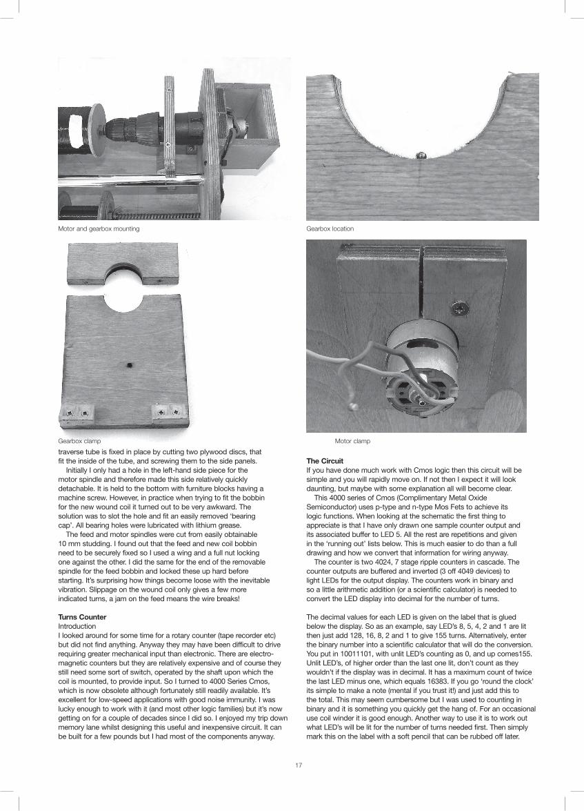
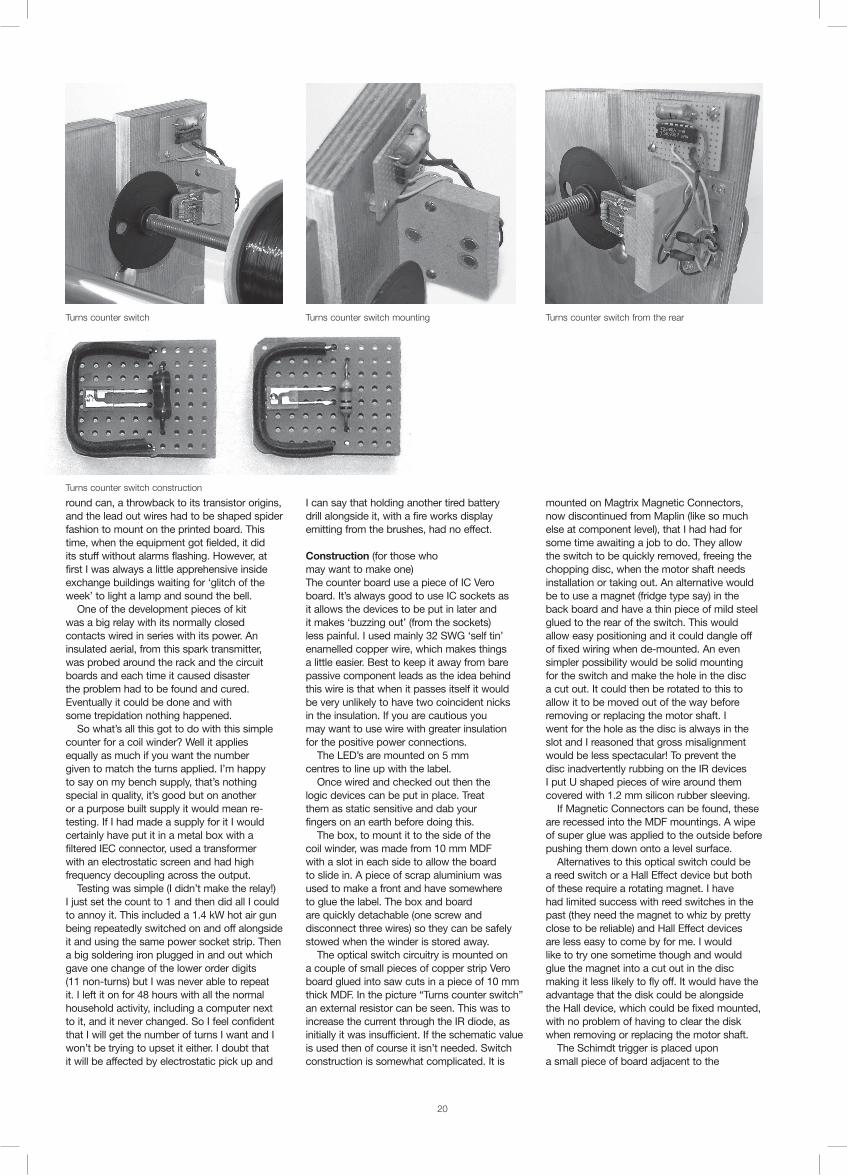
Construction (for those who may want to make one)The counter board use a piece of IC Vero board. It’s always good to use IC sockets as it allows the devices to be put in later and it makes ‘buzzing out’ (from the sockets) less painful. I used mainly 32 SWG ‘self tin’ enamelled copper wire, which makes things a little easier. Best to keep it away from bare passive component leads as the idea behind this wire is that when it passes itself it would be very unlikely to have two coincident nicks in the insulation. If you are cautious you may want to use wire with greater insulation for the positive power connections. The LED’s are mounted on 5 mm centres to line up with the label. Once wired and checked out then the logic devices can be put in place. Treat them as static sensitive and dab your fingers on an earth before doing this. The box, to mount it to the side of the coil winder, was made from 10 mm MDF with a slot in each side to allow the board to slide in. A piece of scrap aluminium was used to make a front and have somewhere to glue the label. The box and board are quickly detachable (one screw and disconnect three wires) so they can be safely stowed when the winder is stored away. The optical switch circuitry is mounted on a couple of small pieces of copper strip Vero board glued into saw cuts in a piece of 10 mm thick MDF. In the picture “Turns counter switch” an external resistor can be seen. This was to increase the current through the IR diode, as initially it was insufficient. If the schematic value is used then of course it isn’t needed. Switch construction is somewhat complicated. It is
mounted on Magtrix Magnetic Connectors, now discontinued from Maplin (like so much else at component level), that I had had for some time awaiting a job to do. They allow the switch to be quickly removed, freeing the chopping disc, when the motor shaft needs installation or taking out. An alternative would be to use a magnet (fridge type say) in the back board and have a thin piece of mild steel glued to the rear of the switch. This would allow easy positioning and it could dangle off of fixed wiring when de-mounted. An even simpler possibility would be solid mounting for the switch and make the hole in the disc a cut out. It could then be rotated to this to allow it to be moved out of the way before removing or replacing the motor shaft. I went for the hole as the disc is always in the slot and I reasoned that gross misalignment would be less spectacular! To prevent the disc inadvertently rubbing on the IR devices I put U shaped pieces of wire around them covered with 1.2 mm silicon rubber sleeving. If Magnetic Connectors can be found, these are recessed into the MDF mountings. A wipe of super glue was applied to the outside before pushing them down onto a level surface. Alternatives to this optical switch could be a reed switch or a Hall Effect device but both of these require a rotating magnet. I have had limited success with reed switches in the past (they need the magnet to whiz by pretty close to be reliable) and Hall Effect devices are less easy to come by for me. I would like to try one sometime though and would glue the magnet into a cut out in the disc making it less likely to fly off. It would have the advantage that the disk could be alongside the Hall device, which could be fixed mounted, with no problem of having to clear the disk when removing or replacing the motor shaft. The Schimdt trigger is placed upon a small piece of board adjacent to the
Turns counter switch Turns counter switch mounting Turns counter switch from the rear
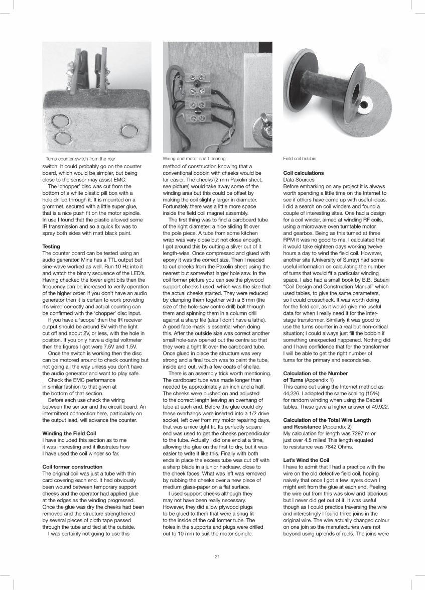
Turns counter switch construction
21
switch. It could probably go on the counter board, which would be simpler, but being close to the sensor may assist EMC. The ‘chopper’ disc was cut from the bottom of a white plastic pill box with a hole drilled through it. It is mounted on a grommet, secured with a little super glue, that is a nice push fit on the motor spindle. In use I found that the plastic allowed some IR transmission and so a quick fix was to spray both sides with matt black paint.
TestingThe counter board can be tested using an audio generator. Mine has a TTL output but sine-wave worked as well. Run 10 Hz into it and watch the binary sequence of the LED’s. Having checked the lower eight bits then the frequency can be increased to verify operation of the higher order. If you don’t have an audio generator then it is certain to work providing it’s wired correctly and actual counting can be confirmed with the ‘chopper’ disc input. If you have a ‘scope’ then the IR receiver output should be around 8V with the light cut off and about 2V, or less, with the hole in position. If you only have a digital voltmeter then the figures I got were 7.5V and 1.5V. Once the switch is working then the disc can be motored around to check counting but not going all the way unless you don’t have the audio generator and want to play safe. Check the EMC performance in similar fashion to that given at the bottom of that section. Before each use check the wiring between the sensor and the circuit board. An intermittent connection here, particularly on the output lead, will advance the counter.
Winding the Field CoilI have included this section as to me it was interesting and it illustrates how I have used the coil winder so far.
Coil former constructionThe original coil was just a tube with thin card covering each end. It had obviously been wound between temporary support cheeks and the operator had applied glue at the edges as the winding progressed. Once the glue was dry the cheeks had been removed and the structure strengthened by several pieces of cloth tape passed through the tube and tied at the outside. I was certainly not going to use this
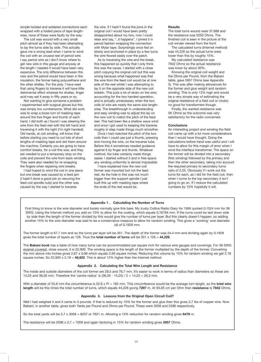
method of construction knowing that a conventional bobbin with cheeks would be far easier. The cheeks (2 mm Paxolin sheet, see picture) would take away some of the winding area but this could be offset by making the coil slightly larger in diameter. Fortunately there was a little more space inside the field coil magnet assembly. The first thing was to find a cardboard tube of the right diameter; a nice sliding fit over the pole piece. A tube from some kitchen wrap was very close but not close enough. I got around this by cutting a sliver out of it length-wise. Once compressed and glued with epoxy it was the correct size. Then I needed to cut cheeks from the Paxolin sheet using the nearest but somewhat larger hole saw. In the coil former picture you can see the plywood support cheeks I used, which was the size that the actual cheeks started. They were reduced by clamping them together with a 6 mm (the size of the hole-saw centre drill) bolt through them and spinning them in a column drill against a sharp file (alas I don’t have a lathe). A good face mask is essential when doing this. After the outside size was correct another small hole-saw opened out the centre so that they were a tight fit over the cardboard tube. Once glued in place the structure was very strong and a final touch was to paint the tube, inside and out, with a few coats of shellac. There is an assembly trick worth mentioning. The cardboard tube was made longer than needed by approximately an inch and a half. The cheeks were pushed on and adjusted to the correct length leaving an overhang of tube at each end. Before the glue could dry these overhangs were inserted into a 1/2 drive socket, left over from my motor repairing days, that was a nice tight fit. Its perfectly square end was used to get the cheeks perpendicular to the tube. Actually I did one end at a time, allowing the glue on the first to dry, but it was easier to write it like this. Finally with both ends in place the excess tube was cut off with a sharp blade in a junior hacksaw, close to the cheek faces. What was left was removed by rubbing the cheeks over a new piece of medium glass-paper on a flat surface. I used support cheeks although they may not have been really necessary. However, they did allow plywood plugs to be glued to them that were a snug fit to the inside of the coil former tube. The holes in the supports and plugs were drilled out to 10 mm to suit the motor spindle.
Coil calculationsData SourcesBefore embarking on any project it is always worth spending a little time on the Internet to see if others have come up with useful ideas. I did a search on coil winders and found a couple of interesting sites. One had a design for a coil winder, aimed at winding RF coils, using a microwave oven turntable motor and gearbox. Being as this turned at three RPM it was no good to me. I calculated that it would take eighteen days working twelve hours a day to wind the field coil. However, another site (University of Surrey) had some useful information on calculating the number of turns that would fit a particular winding space. I also had a small book by B.B. Babani “Coil Design and Construction Manual” which used tables, to give the same parameters, so I could crosscheck. It was worth doing for the field coil, as it would give me useful data for when I really need it for the inter-stage transformer. Similarly it was good to use the turns counter in a real but non-critical situation; I could always just fill the bobbin if something unexpected happened. Nothing did and I have confidence that for the transformer I will be able to get the right number of turns for the primary and secondaries.
Calculation of the Number of Turns (Appendix 1)This came out using the Internet method as 44,226. I adopted the same scaling (15%) for random winding when using the Babani tables. These gave a higher answer of 49,922.
Calculation of the Total Wire Length and Resistance (Appendix 2)My calculation for length was 7297 m or just over 4.5 miles! This length equated to resistance was 7842 Ohms. Let’s Wind the CoilI have to admit that I had a practice with the wire on the old defective field coil, hoping naively that once I got a few layers down I might exit from the glue at each end. Peeling the wire out from this was slow and laborious but I never did get out of it. It was useful though as I could practice traversing the wire and interestingly I found three joins in the original wire. The wire actually changed colour on one join so the manufacturers were not beyond using up ends of reels. The joins were
Turns counter switch from the rear Wiring and motor shaft bearing Field coil bobbin
22 22
Appendix 1 . Calculating the Number of Turns
First thing to know is the wire diameter and books normally give this bare. My trusty Collins Radio Diary for 1956 quoted 0.1524 mm for 38 SWG. Using the Internet method you add on 10% to allow for the coating, which equals 0.16764 mm. If the turns could be laid down side by side then the length of the former divided by this would give the number of turns per layer. But this clearly doesn't happen, so adding
another 15% to the wire diameter was said to be a conservative measure to allow for random winding. This gives a 'working' wire diameter (d) of 0.1928 mm.
The former length is 67.7 mm and so the turns per layer will be 351. The depth of the former was 24.4 mm and dividing again by 0.1928gives the total number of layers as 126. Thus the total number of turns will be 351 x 126 = 44,226.
The Babani book has a table of how many turns can be accommodated per square inch for various wire gauges and coverings. For 38 SWG enamel covered, close wound, it is 22,900. The winding space is the length of the former multiplied by the depth of the former. Converting the mm above into inches gives 2.67 x 0.96 which equals 2.56 square inches. Reducing this volume by 15% for random winding we get 2.18 square inches. So 22,900 x 2.18 = 49,922. This is about 12% higher than the Internet method.
Appendix 2. Calculating the Total Wire Length and Resistance
The inside and outside diameters of the coil former are 28.5 and 76.7 mm. It’s easier to work in terms of radius than diameters so these are 14.25 and 38.35 mm. Therefore the ‘centre radius’ is (38.35 - 14.25) / 2 + 14.25 = 26.3 mm.
With a diameter of 52.6 mm the circumference is 52.6 x Pi = 165 mm. This circumference would be the average turn length, so the total wire length will be this times the total number of turns, which equals 44,226 giving 7297 m. At 93.05 cm per Ohm then resistance is 7842 Ohms.
Appendix 3. Lessons from the Original Open Circuit Coil?
Well I had weighed it and it came to 3 pounds. If that is reduced by 10% for the former and glue then this gives 2.7 lbs of copper wire. Now Babani, in another table, gives both Yards per Pound and Ohms per Pound. These were 3058 and 2596 respectively.
So the total yards will be 2.7 x 3058 = 8257 or 7621 m. Allowing a 15% reduction for random winding gives 6478 m.
The resistance will be 2596 x 2.7 = 7009 and again factoring in 15% for random winding gives 5957 Ohms.
simple twisted and soldered connections each wrapped with a folded piece of tape length-wise, none of these were faulty by the way. The coil was wound with a very small pitch almost as if they had been attempting to lay the turns side by side. This actually gave me a wrong lead when I came to wind the coil with an unused reel of period wire. I say period wire as I don’t know where to get new wire in this gauge and anyway at the length I needed it would have been very expensive. The only difference between the new and the period would have been in the insulation, the former being polyurethane and the other shellac. For the poly. I have read that using fingers to traverse it will have little detrimental effect whereas for shellac, finger acid may eat it away in fifty years or so. Not wanting to give someone a problem I experimented with surgical gloves but this was simply too cumbersome. What did work was to wrap a loose turn of masking tape around the fore finger and thumb of each hand. I did both as I found I was steering the wire from the feed reel with the left hand and traversing it with the right (I’m right handed). Old hands, at coil winding, will know that before starting you need to cut lots of short lengths of masking tape and dot them around the machine. Certainly you are going to have comfort breaks, for a coil this size, and they are needed to put a temporary stop on the coils and prevent the wire from back winding. They were also needed for re-wrapping the fingers when repairing wire breaks. I had hoped to wind the coil in one piece but one break was caused by a feed jam (I hadn’t done a good job on securing the feed coil spindle nuts) and the other was caused by the way I started to traverse
the wire. If I hadn’t found the joins in the original coil I would have been pretty disappointed about my two, now I could relax and say, “..it happens”. I joined it in period fashion wrapping the connection with Mylar tape. Surprisingly once fed on slowly and anchored in place by a few turns the wire flowed easily over the patch. As to traversing the wire and the break, this happened so quickly that I only think this was the cause. I started with a close pitch copying the original coil but this was wrong because what happened was that the wire from the feed coil would be at one side of the reel whilst I was attempting to lay it on the opposite side of the new coil bobbin. This puts a lot of strain on the wire; accounting for the two handed operation, and is actually unnecessary when the two coils of wire are nearly the same size length-wise. The breakthrough in understanding and easy winding was to adjust the lay on the new coil to match the pitch of the feed reel. This had been like a shallow wave wind and once I got used to keeping the traverse roughly in step made things much smoother. Once I had matched the pitch of the two coils then I could use just a thumb, pressing and moving the wire, on the traverse tube. Before this it sometimes needed guidance against it by finger and thumb. Whatever method, the tube certainly made things easier. I started without it and in free space any winding uniformity is almost impossible. I have explained how the new coil former was mounted but not the feed reel. As the hole in this was not much bigger than the support spindle I just built this up with masking tape where the ends of the reel would be.
ResultsThe total turns wound were 37,688 and the resistance was 5250 Ohms. The finished coil is seen in the picture of the coil winder viewed from the front. The calculated turns (Internet method) was 44,226 so the actual turns were lower than this by roughly 15%. My calculated resistance was 7842 Ohms so the actual resistance was lower by about 30%. Knowing the original coil weight and the Ohms per Pound, from the Babani table, gave 5957 Ohms (see Appendix 3). This was after making allowances for the former and glue weight and random winding. This is only 13% high and would be a very simple way of estimating the original resistance of a field coil or choke: no good for transformers though. Finally, the wanted resistance was 5K Ohms so the outcome was very satisfactory for the radio concerned.
ConclusionsAn interesting project and winding the field coil came up with a lot more considerations than I would have thought. Doing the calculations before hand was useful and I will have to allow for this margin of error when I wind the interface transformer. The space on the former will be divided into a secondary (first winding) followed by the primary and then the other secondary, taking into account the required primary to secondary turns ratio of 2.25. Obviously if I work out the turns for each, as I did for the field coil, then when I come to the top secondary it isn’t going to go on. If I reduce the calculated numbers by 15% hopefully it will.