Embed Size (px)
Citation preview
Making Sure Resets Don’t Kill Your SoCs
Vikas Sachdeva
Real Intent Inc., Sunnyvale, CA
2
I. INTRODUCTION
The primary purpose of reset in a digital design is to initialize the hardware for system
operation by forcing the design into a known state. Verifying design initialization is a critical
part of design verification as failures can lead to functionality hazards or design re-spins.
With increasing design complexity, reset design architecture is also becoming more
complex.
Modern SoCs often have multiple power-on-resets that stage initialization of the chip
when power is turned on. Staging minimizes simultaneous switching that can cause other
issues. In addition to power-on-resets, there are also software resets, debug resets, low-
power resets, low-voltage resets, global resets and local resets. All these resets can be
independently asserted and de-asserted at any time during chip operation. In this paper I
review the fundamentals that engineers follow in designing complex reset architectures. I
then elaborate some of the failures that can occur if reset design fundamentals are not
followed, and introduce Meridian RDC, a static verification tool that aids in ensuring a robust
reset design.
II. Reset Design Fundamentals
While implementing complex reset architectures, designers follow simple reset design fundamentals. Some of these basic fundamentals are shown below
• Reset paths should be glitch free
Glitches on reset paths can be hazardous and lead to metastability or other functional failures in the system. Designers must therefore take special care to ensure there are no glitches on reset paths.
• Combinational loops on reset paths should be avoided
Combinational loops on resets can cause unpredictable behavior in silicon. Designers try to avoid combinational loops on reset paths to ensure safe functionality.
• Reconvergence on reset paths should be properly analyzed
Designers try to avoid reconvergence on reset paths as much as possible. If it’s not possible to avoid reconvergent paths, those paths must be properly scrutinized to ensure that they don’t lead to functional failures.
• Resets crossing clock-domain boundary should be properly synchronized
These are reset signals that cross the asynchronous clock domain boundary. Designers must add reset synchronizers to ensure the resets are properly synchronized so metastability does not propagate in the design.
• Paths crossing a reset-domain boundary must be made safe
Metastability due to asynchronous clock-domain crossing is a well-known problem. However metastability can also manifest in the design when the reset of a source register is unrelated to the reset of the destination register. These paths are referred to as Reset Domain Crossing (RDC), and like CDC crossings, can be subject to metastability when the reset subsystems operate asynchronously in the design.
• Avoid reconvergence or loss of correlation of synchronized resets
When multiple resets are synchronized it may take one or more clock cycles to capture it, depending upon arrival time of active clock edges. If multiple resets are being synchronized some of the resets can be captured in the first clock cycle while others are captured in the second clock cycle. This may result loss of correlation in the destination side.
3
While reset design fundamentals are well known to an experienced reset designer, with increasing complexity of the reset architecture, it is becoming more and more difficult to ensure that these design fundamentals are being followed in the whole SoC and across the many functional modes.
III. Typical Reset Failures
In the previous section I discussed reset design fundamentals. In this section I will review some of the failures that can occur if those reset design fundamentals are not followed.
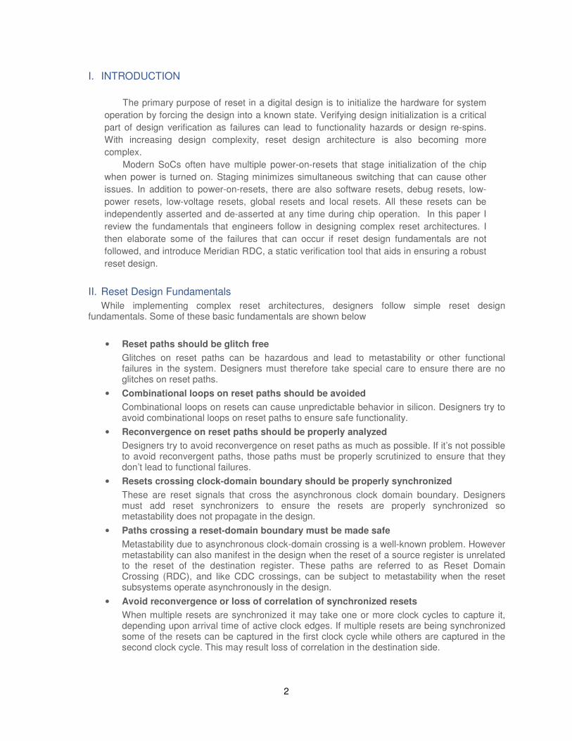
Consider the circuit below in Figure1. It has two resets, Test reset and Soft reset which go
through some combinational logic before they feed the asynchronous reset pin of the flop. If transitions in Mode sel are not properly sequenced with respect to Test reset and Soft reset
a glitch can be introduced on the reset pin of the flop that can propagate further down and lead to functional failure.
Figure1 (a): Reset Glitch Structure
Figure1 (b): Reset Glitch Waveform
4
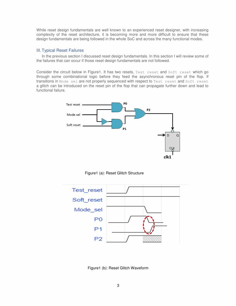
In the circuit below in Figure 2, the output of the flop that clocks RST-A is going from the
clk1 domain to the clk2 domain. If clk1 and clk2 are asynchronous to each other, the
clocked RST-A value can change at or near the active clk2 edge of the receiving flip-flop.
This can cause the output of the receiving clk2 flop to go metastable.
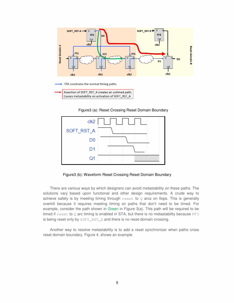
In the circuit below in Figure 3, the paths shown in blue are paths that are timed in STA.
The assertion of SOFT_RST_A creates a path shown in Red that is not timed in STA by
default. This can cause metastability in the destination flop that can propagate further in the
design and lead to functional failures. Note that there is only one clock domain in the design
implying that metastability can occur with just one clock domain.
Figure2 (a): Reset Crossing Clock Domain Boundary
Figure2 (b): Waveform Reset Crossing Clock Domain Boundary
5
There are various ways by which designers can avoid metastability on these paths. The
solutions vary based upon functional and other design requirements. A crude way to
achieve safety is by meeting timing through reset to Q arcs on flops. This is generally
overkill because it requires meeting timing on paths that don’t need to be timed. For
example, consider the path shown in Green in Figure 3(a). This path will be required to be
timed if reset to Q arc timing is enabled in STA, but there is no metastability because FF3
is being reset only by SOFT_RST_A and there is no reset-domain crossing.
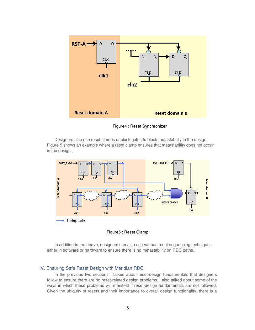
Another way to resolve metastability is to add a reset synchronizer when paths cross
reset domain boundary. Figure 4. shows an example
Figure3 (a): Reset Crossing Reset Domain Boundary
Figure3 (b): Waveform Reset Crossing Reset Domain Boundary
6
Designers also use reset clamps or clock gates to block metastability in the design.
Figure 5 shows an example where a reset clamp ensures that metastability does not occur
in the design.
In addition to the above, designers can also use various reset sequencing techniques
either in software or hardware to ensure there is no metastability on RDC paths.
IV. Ensuring Safe Reset Design with Meridian RDC
In the previous two sections I talked about reset-design fundamentals that designers
follow to ensure there are no reset-related design problems. I also talked about some of the
ways in which these problems will manifest if reset-design fundamentals are not followed.
Given the ubiquity of resets and their importance to overall design functionality, there is a
Figure4 : Reset Synchronizer
Figure5 : Reset Clamp
7
need for a tool that enables signing-off on the reset design, similar to CDC sign-off. The
requirements of this tool and associated methodology are as follows:
1. Ability to identify all problematic areas in the design where reset-design
fundamentals are not followed
2. Ability for user to define reset sequencing and complex reset schemes
3. Ability to identify the eventual consequence of metastability in the design to
minimize noise (e.g. don’t report issues that have no consequence).
4. Must provide precise debug information that facilitates quickly pinpointing the
root cause of the RDC problem.
5. It is also useful to be able to identify safe areas in the design where reset
design fundamentals are being followed.
STA or home grown scripting-based solutions don’t have an inherent understanding of reset
design fundamentals and they fail to meet the above criteria. They generally are noisy in that
they report more issues than are real issues, and they also miss real issues. Also STA tools
don’t support specifying reset sequencing or complex reset schemes.
Meridian RDC, Real Intent’s RDC Sign-off solution addresses all of the above requirements
to ensure safe reset design. It has an inherent understanding of reset-design fundamentals
and reports violations where those reset fundamentals are not followed. It also reports paths
that are safe RDC crossings where reset-design fundamentals are followed. The user can
provide information about reset sequencing and directional relationships among resets to
fine tune reset analysis. It performs comprehensive static analysis to ensure that signals
crossing reset domains function reliably. Among other things, Meridian RDC identifies
metastability problems arising from software and/or low power resets.
Reset paths are pervasive in the design and simplistic analysis can lead to hundreds of
thousands of crossings to be reviewed for typical designs. Meridian RDC distinguishes itself
by using sequencing and directional analysis to accurately identify only the problematic paths.
This leads to low noise results and saves valuable analysis time.
In addition to the above, RDC has smart reporting and a powerful GUI that keeps users
focused on important issues through an efficient organization of findings. Helpful guidance
and suggested actions help users pinpoint the source of the problems quickly. All the RDC
analysis data is stored in a database that can be accessed through the GUI or command line
interface. Users can customize the debug methodology to match their design flows using
spreadsheet reports, graphical reports, scripting, and so on. Meridian RDC supports an
integrated visualization tool. For example, pruned schematic views focus on fault-related
logic, and with a few mouse clicks, users are directed to the RTL source code that caused
the problem. This debug approach allows for easy investigation deep into the design to
isolate the root cause for any warnings and errors.
8
V. SUMMARY
Poor reset architecture and design can result in unreliable functional resets, causing
intermittent catastrophic chip failures. These chip-killer errors are not caught in static
solutions like STA, clock-domain crossing (CDC) tools, or through simulation. They result in
chip failures in the field that are difficult to diagnose and expensive to fix. Reset functionality
may be incorrect due to metastability, glitches on asynchronous resets, or reconvergence of
synchronized resets. Metastability may result at a reset-domain crossing when an
asynchronous reset is asserted or deasserted. Glitches may cause spurious resets when an
asynchronous reset is generated by combinatorial logic. Functional loss of correlation of
synchronized resets may result from reconvergence.
Meridian RDC is the only solution in the industry that automatically extracts resets and
reset domains and performs precise RDC analysis. Meridian RDC’s unique technology
allows designers to use effective strategies to guarantee a robust reset design. Since reset
paths are pervasive in the design, simplistic analysis can lead to hundreds of thousands of
crossings to be reviewed for typical designs. Meridian RDC distinguishes itself by using
sequencing and directional analysis to accurately identify only the problematic paths. This
leads to low noise results and saves valuable analysis time. This also enables Meridian
RDC to verify all aspects of a reset design. Meridian RDC was developed with several
partners that have helped to refine the presentation of violations, and to provide ample
debug information to help the user to understand the cause and effect of the violation. For
users of the Meridian CDC companion product, it is possible to suppress CDC-related reset
violations that would also be reported by Meridian CDC. This avoids any overlap and
ensures efficiency. Reset-design sign-off is key for SoC safety. Crucially, Meridian RDC is
also an integral tool for tracking conformance to processes driven by DO-254 and ISO
26262.
9
REFERENCES [1] http://www.realintent.com/real-intent-products/meridian-rdc/
2017-01-06, v1 Copyright © 2017 Real Intent Inc.
Real Intent, Inc.
990 Almanor Avenue, Suite 220
Sunnyvale, CA 94085
Phone: 408-830-0700
Fax: 408-737-1962 realintent.com


![SECCHI Status 2014.ppt [Read-Only] - STEREO...•SECCHI Electronics Box –Watchdog Resets: “Random” resets of the 750 CPU of unknown origin, For year AB 2007 5 4 Watchdog Resets:](https://img.pdfslide.net/doc/110x75/5f672017bee7a75286313eae/secchi-status-2014ppt-read-only-stereo-asecchi-electronics-box-awatchdog.jpg)