Embed Size (px)
Citation preview

MS 1525:2014
MALAYSIAN STANDARD
Energy efficiency and use of renewable energy for non-residential buildings - Code of practice (Second revision)
ICS: 91.040.01 Descriptors: energy efficiency, renewable energy, non-residential, buildings, code of practice, energy
© Copyright 2014
DEPARTMENT OF STANDARDS MALAYSIA
Lice
nsed
to U
NIV
ER
SIT
I MA
LAY
SIA
PE
RLI
S (
UN
IMA
P)
/ Dow
nloa
ded
on :
10-D
ec-2
014
10:5
6:02
AM
/ S
ingl
e us
er li
cens
e on
ly, c
opyi
ng a
nd n
etw
orki
ng p
rohi
bite
d

DEVELOPMENT OF MALAYSIAN STANDARDS The Department of Standards Malaysia (STANDARDS MALAYSIA) is the national standards and accreditation body of Malaysia. The main function of STANDARDS MALAYSIA is to foster and promote standards, standardisation and accreditation as a means of advancing the national economy, promoting industrial efficiency and development, benefiting the health and safety of the public, protecting the consumers, facilitating domestic and international trade and furthering international cooperation in relation to standards and standardisation. Malaysian Standards (MS) are developed through consensus by committees which comprise balanced representation of producers, users, consumers and others with relevant interests, as may be appropriate to the subject at hand. To the greatest extent possible, Malaysian Standards are aligned to or are adoption of international standards. Approval of a standard as a Malaysian Standard is governed by the Standards of Malaysia Act 1996 [Act 549]. Malaysian Standards are reviewed periodically. The use of Malaysian Standards is voluntary except in so far as they are made mandatory by regulatory authorities by means of regulations, local by-laws or any other similar ways. For the purposes of Malaysian Standards, the following definitions apply: Revision: A process where existing Malaysian Standard is reviewed and updated which resulted in the publication of a new edition of the Malaysian Standard. Confirmed MS: A Malaysian Standard that has been reviewed by the responsible committee and confirmed that its contents are current. Amendment: A process where a provision(s) of existing Malaysian Standard is altered. The changes are indicated in an amendment page which is incorporated into the existing Malaysian Standard. Amendments can be of technical and/or editorial nature. Technical corrigendum: A corrected reprint of the current edition which is issued to correct either a technical error or ambiguity in a Malaysian Standard inadvertently introduced either in drafting or in printing and which could lead to incorrect or unsafe application of the publication. NOTE: Technical corrigenda are not to correct errors which can be assumed to have no consequences in the application of the MS, for example minor printing errors. STANDARDS MALAYSIA has appointed SIRIM Berhad as the agent to develop, distribute and sell Malaysian Standards. For further information on Malaysian Standards, please contact: Department of Standards Malaysia OR SIRIM Berhad Ministry of Science, Technology and Innovation (Company No. 367474 - V) Level 1 & 2, Block 2300, Century Square 1, Persiaran Dato’ Menteri Jalan Usahawan Section 2, P. O. Box 7035 63000 Cyberjaya 40700 Shah Alam Selangor Darul Ehsan Selangor Darul Ehsan MALAYSIA MALAYSIA Tel: 60 3 8318 0002 Tel: 60 3 5544 6000 Fax: 60 3 8319 3131 Fax: 60 3 5510 8095 http://www.jsm.gov.my http://www.sirim.my E-mail: [email protected] E-mail: [email protected]
Lice
nsed
to U
NIV
ER
SIT
I MA
LAY
SIA
PE
RLI
S (
UN
IMA
P)
/ Dow
nloa
ded
on :
10-D
ec-2
014
10:5
6:02
AM
/ S
ingl
e us
er li
cens
e on
ly, c
opyi
ng a
nd n
etw
orki
ng p
rohi
bite
d

MS 1525:2014
© STANDARDS MALAYSIA 2014 - All rights reserved i
Contents
Page Committee representation .......................................................................................................... ii Foreword ..................................................................................................................................... v Introduction ................................................................................................................................ vi 1 Scope ............................................................................................................................. 1 2 Normative references .................................................................................................... 1 3 Terms and Definitions .................................................................................................... 2
4 Architectural and passive design strategy ..................................................................... 3 5 Building envelope ........................................................................................................ 13 6 Lighting ........................................................................................................................ 24 7 Electric power and distribution..................................................................................... 31 8 Air-conditioning and mechanical ventilation (ACMV) system ...................................... 37 9 Energy management control system ........................................................................... 50 10 Building energy simulation method (an alternative compliance method) .................... 60
Lice
nsed
to U
NIV
ER
SIT
I MA
LAY
SIA
PE
RLI
S (
UN
IMA
P)
/ Dow
nloa
ded
on :
10-D
ec-2
014
10:5
6:02
AM
/ S
ingl
e us
er li
cens
e on
ly, c
opyi
ng a
nd n
etw
orki
ng p
rohi
bite
d
MS 1525:2014
© STANDARDS MALAYSIA 2014 - All rights reserved ii
Committee representation The Industry Standards Committee on Building, Construction and Civil Engineering (ISC D) under whose authority this Malaysian Standard was developed, comprises representatives from the following organisations: Association of Consulting Engineers Malaysia Construction Industry Development Board Malaysia Department of Irrigation and Drainage Malaysia Department of Standards Malaysia Dewan Bandaraya Kuala Lumpur Federation of Malaysian Manufacturers Jabatan Bomba dan Penyelamat Malaysia Jabatan Kerajaan Tempatan Jabatan Kerja Raya Malaysia Malaysian Timber Council Malaysian Timber Industry Board Master Builders Association Malaysia Pertubuhan Akitek Malaysia Projek Lebuhraya Utara-Selatan Berhad Real Estate and Housing Developers' Association Malaysia SIRIM Berhad (Secretariat) Suruhanjaya Perkhidmatan Air Negara The Cement and Concrete Association of Malaysia The Institution of Engineers, Malaysia Universiti Sains Malaysia Universiti Teknologi Malaysia The Technical Committee on Energy Efficiency in Buildings (Passive) which supervised the development of this Malaysian Standard consists of representatives from the following organisations: Association of Consulting Engineers Malaysia Federation of Malaysian Manufacturers International Islamic University of Malaysia Jabatan Kerja Raya Malaysia Pertubuhan Akitek Malaysia SIRIM Berhad (Secretariat) SIRIM QAS International Sdn Bhd Suruhanjaya Tenaga Universiti Islam Antarabangsa Malaysia Universiti Teknologi Malaysia Universiti Teknologi MARA The following working groups developed this Malaysian Standard: The Working Group on Architecture and Passive Design Strategy which consists of representatives from the following organisations: Malaysia Green Building Confederation SIRIM Berhad (Secretariat) Suruhanjaya Tenaga Universiti Islam Antarabangsa Malaysia Universiti Putra Malaysia Universiti Teknologi MARA
Lice
nsed
to U
NIV
ER
SIT
I MA
LAY
SIA
PE
RLI
S (
UN
IMA
P)
/ Dow
nloa
ded
on :
10-D
ec-2
014
10:5
6:02
AM
/ S
ingl
e us
er li
cens
e on
ly, c
opyi
ng a
nd n
etw
orki
ng p
rohi
bite
d
MS 1525:2014
© STANDARDS MALAYSIA 2014 - All rights reserved iii
Committee representation (continued) The Working Group on Air-conditioning and Mechanical Ventilation (ACMV) System & Energy Management Control System which consists of representatives from the following organisations: Acson Malaysia Sales & Service Sdn Bhd Association of Consulting Engineers Malaysia Carrier (Malaysia) Sdn Bhd Daikin Air Conditioning (Malaysia) Sdn Bhd Dunham-Bush (Malaysia) Bhd Federation of Malaysian Manufacturers Group Associated (C&L) Sdn Bhd Jabatan Kerja Raya Malaysia Malaysia Chapter of American Society of Heating, Refrigerating and Air-Conditioning Engineers (MASHRAE) Malaysian Air Conditioning and Refrigeration Association (MACRA) O.Y.L Industries Sdn Bhd SIRIM Berhad (Secretariat) Superior Make Aircon Refrigeration Tech Sdn Bhd The Institution of Engineers, Malaysia Trane Malaysia TM Sales and Services Sdn Bhd York (Malaysia) Sales & Service Sdn Bhd The Working Group on Lighting which consists of representatives from the following organisations: Association of Consulting Engineers Malaysia Federation of Malaysian Manufacturers Jabatan Kerja Raya Malaysia Phillips (M) Sdn Bhd SIRIM Berhad (Secretariat) SIRIM QAS International Sdn Bhd Tenaga Nasional Berhad The Electrical and Electronics Association of Malaysia The Institution of Engineers, Malaysia The Working Group on Electric Power and Distribution which consists of representatives from the following organisations: Association of Consulting Engineers Malaysia Federation of Malaysian Manufacturers Jabatan Kerja Raya Malaysia SIRIM Berhad (Secretariat) Suruhanjaya Tenaga The Working Group on Energy Management System (EMS) which consists of representatives from the following organisations: Association of Consulting Engineers Malaysia BICT Engineering Sdn Bhd Federation of Malaysian Manufacturers George Kent (M) Bhd Honeywell Sdn Bhd Jabatan Kerja Raya Malaysia Johnson Controls (M) Sdn Bhd M&C Engineering and Trading Sdn Bhd Malaysia Chapter of American Society of Heating, Refrigerating and Air-Conditioning Engineers (MASHRAE) Malaysian Air Conditioning and Refrigeration Association (MACRA) Metronic Engineering Sdn Bhd SIRIM Berhad (Secretariat) Solar District Cooling Sdn Bhd The Institution of Engineers, Malaysia
Lice
nsed
to U
NIV
ER
SIT
I MA
LAY
SIA
PE
RLI
S (
UN
IMA
P)
/ Dow
nloa
ded
on :
10-D
ec-2
014
10:5
6:02
AM
/ S
ingl
e us
er li
cens
e on
ly, c
opyi
ng a
nd n
etw
orki
ng p
rohi
bite
d

MS 1525:2014
© STANDARDS MALAYSIA 2014 - All rights reserved iv
Committee representation (concluded) The Working Group on Overall Transfer Thermal Value (OTTV) which consists of representatives from the following organisations: Building Sector Energy Efficiency Project Federation of Malaysian Manufacturers Malaysia Green Building Confederation Malaysian Sheet Glass Sdn Bhd Pertubuhan Akitek Malaysia SIRIM Berhad (Secretariat) The Institution of Engineers, Malaysia Universiti Putra Malaysia
Lice
nsed
to U
NIV
ER
SIT
I MA
LAY
SIA
PE
RLI
S (
UN
IMA
P)
/ Dow
nloa
ded
on :
10-D
ec-2
014
10:5
6:02
AM
/ S
ingl
e us
er li
cens
e on
ly, c
opyi
ng a
nd n
etw
orki
ng p
rohi
bite
d

MS 1525:2014
© STANDARDS MALAYSIA 2014 - All rights reserved v
Foreword This Malaysian Standard was developed by the Technical Committee on Energy Efficiency in Buildings (Passive) under the authority of the Industry Standards Committee on Building, Construction and Civil Engineering. Major modifications of this revision are as follows: a) improvement to description on passive design strategies especially daylighting and
facade design; b) diagrammatic representation of shading coefficients; c) improved power intensities and inclusion of Colour Rendering Index (CRI); d) efficiency classification for motors according to IEC; e) introduction of MPLV (Malaysia Part Load Value); and f) prerequisites for optimizing EMS operation. This Malaysian Standard cancels and replaces MS 1525:2007, Code of practice on energy efficiency and use of renewable energy for non-residential buildings (First revision). This Malaysian Standard has been republished to incorporate editorial amendment AMD 1:2014. Compliance with a Malaysian Standard does not of itself confer immunity from legal obligations.
Lice
nsed
to U
NIV
ER
SIT
I MA
LAY
SIA
PE
RLI
S (
UN
IMA
P)
/ Dow
nloa
ded
on :
10-D
ec-2
014
10:5
6:02
AM
/ S
ingl
e us
er li
cens
e on
ly, c
opyi
ng a
nd n
etw
orki
ng p
rohi
bite
d

MS 1525:2013
vi © STANDARDS MALAYSIA 2014 - All rights reserved
Introduction The purposes of this Malaysian Standard are to: a) encourage the design, construction, operation and maintenance of new and existing
buildings in a manner that reduces the use of energy without constraining creativity in design, building function and the comfort or productivity of the occupants; and appropriately dealing with cost considerations;
b) provide the criteria and minimum standards for energy efficiency in the design of new
buildings, retrofit of existing buildings and methods for determining compliance with these criteria and minimum standards;
c) provide guidance for energy efficiency designs that demonstrate good professional
judgment to comply with minimum standards; and d) encourage the application of renewable energy in new and existing buildings to
minimise reliance on non-renewable energy sources, pollution and energy consumption whilst maintaining comfort, health and safety of the occupants.
As the standard sets out only the minimum requirements, designers are encouraged to design and select equipment above those stipulated in this standard. The recommendations for good practice in renewable energy applications are classified under the following areas: a) maximising passive solar design; b) optimising passive cooling strategies; c) optimising environmental cooling through natural means such as vegetation, site
planning, landscaping and shading; and d) maximising the availability of renewable energy resources such as solar heating, solar
electricity, solar lighting and solar assisted technologies. The requirements for energy efficiency are classified under the following areas: a) designing an efficient lighting system (Clause 6); b) minimising losses in electrical power distribution equipment (Clause 7); c) designing an efficient air-conditioning and mechanical ventilation system (Clause 8);
and d) designing a good energy management system (Clause 9).
Lice
nsed
to U
NIV
ER
SIT
I MA
LAY
SIA
PE
RLI
S (
UN
IMA
P)
/ Dow
nloa
ded
on :
10-D
ec-2
014
10:5
6:02
AM
/ S
ingl
e us
er li
cens
e on
ly, c
opyi
ng a
nd n
etw
orki
ng p
rohi
bite
d

MS 1525:2014
© STANDARDS MALAYSIA 2014 - All rights reserved 1
Energy efficiency and use of renewable energy for non-residential buildings - Code of practice
1 Scope This code of practice gives guidance on the effective use of energy including the application of renewable energy in new and existing non-residential buildings. Buildings or portions thereof whose peak design rate of electrical energy usage for all purposes is less than 10 W/m2 (installed) of gross floor area are excluded from this standard. Where specifically noted in this standard, certain other buildings or elements thereof may be exempted when design data are not available or applicable.
2 Normative references The following normative references are indispensable for the application of this standard. For dated references, only the edition cited applies. For undated references, the latest edition of the normative references (including any amendments) applies. MS 825, Code of practice for the design of road lighting (all parts) MS 2449, Performance rating of water-chilling packages using the vapor compression cycle MS IEC 8995, Lighting of indoor work places (ISO 8995:2002, IDT) MS IEC 60287-3-2, Electric cables - Calculation of the current rating - Part 3: Sections on operating conditions - Section 2: Economic optimization of power cable size (IEC 60287-3-2:1995, and its Amendment 1:1996, IDT) MS IEC 60364, Electrical installations of buildings MS IEC 60364-5-52, Electrical installations of buildings - Part 5-52: Selection and erection of electrical equipment - Wiring systems (IEC 60364-5-52:2001, IDT) MS IEC 60929, Specification for a.c. supplied electronic ballasts for tubular fluorescent lamps - Performance requirements ASHRAE Handbook - HVAC systems and equipment ANSI/SMACNA 006, HVAC Duct Construction Standards Metal and Flexible, SMACNA
AHRI 210-240, Performance Rating of Unitary Air-Conditioning & Air-Source Heat Pump Equipment
ANSI/AHRI 340/360, Commercial and Industrial Unitary Air-Conditioning and Heat Pump Equipment AHRI 550/590, Performance Rating of Water Chilling Packages Using the Vapor Compression Cycle ARI 480, Refrigerant-Cooled Liquid Coolers, Remote Type
Lice
nsed
to U
NIV
ER
SIT
I MA
LAY
SIA
PE
RLI
S (
UN
IMA
P)
/ Dow
nloa
ded
on :
10-D
ec-2
014
10:5
6:02
AM
/ S
ingl
e us
er li
cens
e on
ly, c
opyi
ng a
nd n
etw
orki
ng p
rohi
bite
d
MS 1525:2014
2 © STANDARDS MALAYSIA 2014 - All rights reserved
ANSI/ASHRAE 140, Standard Method of Test for the Evaluation of Building Energy Analysis Computer Programs Uniform Building By Laws, 1984 HVAC Air Duct Leakage Test Manual, SMACNA
3 Terms and definitions For the purpose of this standard, the following shall apply. 3.1 building envelope The exterior portions of a building through which thermal energy is transferred. NOTE. This thermal transfer is the major factor affecting interior comfort level and the air-conditioning load.
3.2 coefficient of performance This is the ratio of the rate of net heat removal to the rate of total energy input, expressed in consistent units and under designed rating conditions. 3.3 cross ventilation Cross ventilation is the flow of air through a building due to a wind-generated pressure drop across it. 3.4 fenestration A glazed opening in building wall to control solar radiant heat and daylighting. NOTES: 1. Most common forms include windows and clerestories. 2. Sometimes a fenestration may include its associated interior and exterior elements such as shades and blinds.
3.5 kilowatt refrigeration (kWr) The unit used to denote refrigeration capacity in kW. NOTE. 1 kWr = 3412 Btuh
3.6 Overall Thermal Transfer Value (OTTV) The design parameter that indicates the solar thermal load transmitted through the building envelope excluding the roof. 3.7 radiant barrier Radiant barrier is material that either reflects radiant heat or inhibits the emission of radiant heat.
Lice
nsed
to U
NIV
ER
SIT
I MA
LAY
SIA
PE
RLI
S (
UN
IMA
P)
/ Dow
nloa
ded
on :
10-D
ec-2
014
10:5
6:02
AM
/ S
ingl
e us
er li
cens
e on
ly, c
opyi
ng a
nd n
etw
orki
ng p
rohi
bite
d
MS 1525:2014
© STANDARDS MALAYSIA 2014 - All rights reserved 3
3.8 Roof Thermal Transfer Value (RTTV) The design parameter that indicates the solar thermal load transmitted through the roof. 3.9 shading coefficient The shading coefficient of the fenestration system is the ratio of solar heat gain through the fenestration system to the solar heat gain through an unshaded 3 mm clear glass under the same condition. 3.10 skylight A glazed opening, horizontal or inclined, which is set into roof of a building to provide daylighting.
4 Architectural and passive design strategy 4.1 Sustainable design approach Designing within the contextual climate and site are the first steps to optimise the benefits provided by the specific environment. Design solutions shall strive to achieve energy efficiency and to use environmentally friendly materials of high quality and durability in order to decrease waste. A combined architectural, engineering, site planning and landscaping (holistic) approach to designing an energy efficient building would optimise the energy efficiency of a building especially when employing combined passive and active devices. For example, adopting mixed mode systems, i.e. optimising daylighting and thermal comfort while reducing solar heat gain would be a strategy to achieve energy efficiency. 4.2 Passive design strategy The basic approach towards good passive design is to orientate, to shade, to insulate, to ventilate and to daylight buildings. Buildings have a primary function to provide an internal environment suitable for the purpose of the building. The architectural passive design consideration in designing a building is primarily influenced by its responsiveness to its site context. The important factors that should be considered include the following: a) site planning and orientation; b) daylighting; c) facade design; d) natural ventilation; e) thermal insulation; f) strategic landscaping; and g) renewable energy.
Lice
nsed
to U
NIV
ER
SIT
I MA
LAY
SIA
PE
RLI
S (
UN
IMA
P)
/ Dow
nloa
ded
on :
10-D
ec-2
014
10:5
6:02
AM
/ S
ingl
e us
er li
cens
e on
ly, c
opyi
ng a
nd n
etw
orki
ng p
rohi
bite
d

MS 1525:2014
4 © STANDARDS MALAYSIA 2014 - All rights reserved
These factors are just as important as the selection of active systems or devices to control visual and thermal comfort within the building, and need not impose any significant cost as compared to a more highly serviced building. 4.3 Site planning and orientation Site planning and orientation is an important consideration in architectural and passive design strategy. The basic principle of good orientation in equatorial region is to avoid exposure of openings to the intense solar radiation from East and West. The general rule for best orientation of buildings is to avoid facades with most openings facing East or West. Technically for buildings with rectangular plans the buildings’ main longitudinal
orientation should be on an axis 5 Northeast (see Figure 1 and 2). On narrow sites where the East-West longitudinal orientation may not be possible, the solutions may require other building geometries. In this case, the shading devices recommended may differ according to orientation (refer to shading coefficient values for external shading devices, in 5.3.3). The orientation of buildings may also contribute to the immediate microclimate of open spaces through the provision of shading and shadowing to the immediate surroundings that will in turn benefit the indoor areas adjacent to it. The microclimate information (air temperature, radiant temperature, relative humidity, air velocity and precipitation, etc) should be analysed for the specific locality. 4.4 Daylighting Designing with emphasis on day lighting should begin at the preliminary design stage. A good day lighting system should consider the following:
a) space orientation and organisation; b) physical (shape and size) and optical properties of glazing through which daylight will
transmit or penetrate; c) internal floor, wall and ceiling surface properties (colour and reflectivity); d) visual contrast between adjacent surfaces (e.g between walls and ceilings); and e) protection from visual discomfort (e.g glare and silhouette) caused by external and
internal building elements. Conventional and innovative day lighting strategies that collect transport and distribute light into buildings with deep plans and systems that reduce the need for artificial lighting without increasing solar heat gain, are recommended. 4.4.1 Daylight distribution The simplest form of description of the daylight distribution, penetration and intensity is the Daylight Factor (DF), expressed as a percentage. This is the ratio of the internal illuminance (Einternal) at a point in a room to the instantaneous external illuminance (Eexternal) on a horizontal surface:
%100 external
internal
E
EDF
Lice
nsed
to U
NIV
ER
SIT
I MA
LAY
SIA
PE
RLI
S (
UN
IMA
P)
/ Dow
nloa
ded
on :
10-D
ec-2
014
10:5
6:02
AM
/ S
ingl
e us
er li
cens
e on
ly, c
opyi
ng a
nd n
etw
orki
ng p
rohi
bite
d

MS 1525:2014
© STANDARDS MALAYSIA 2014 - All rights reserved 5
As a guide, the brightness inside a building and the associated distribution can be classified by the daylight factors as shown in Tables 1a, 1b and 1c.
Table 1a. Daylight factors and impact
DF (%) Lighting Glare Thermal comfort
> 6.0 Intolerable Intolerable Uncomfortable
3.5 - 6.0 Tolerable Uncomfortable Tolerable
1.0 - 3.5 Acceptable Acceptable Acceptable
< 1.0 Perceptible Imperceptible Acceptable
Table 1b. Internal illuminance
DF Ext (lux) 1 2 3 4 5 6
5 000 50 100 150 200 250 300
10 000 100 200 300 400 500 600
20 000 200 400 600 800 1 000 1 200
30 000 300 600 900 1 200 1 500 1 800
40 000 400 800 1 200 1 600 2 000 2 400
50 000 500 1 000 1 500 2 000 2 500 3 000
60 000 600 1 200 1 800 2 400 3 000 3 600
70 000 700 1 400 2 100 2 800 3 500 4 200
80 000 800 1 600 2 400 3 200 4 000 4 800
Table 1c. Sky conditions
Sky conditions
Sky type Description Cloud cover (%)
Sky Illuminance (lux)
Standard overcast
Sun not visible;sky covered with thick, milky white cloud
100 5 000 - 20 000
Cloudy Sky partially
covered by cloud > 70 20 000 - 100 000
Intermediate Sky mostly covered with 30 % to 70 %
cloud 30 - 70 30 000 - 100 000
Clear blue sky Sky with almost no
cloud < 30 50 000 - 100 000
NOTE. In general the sky type in Malaysia can be classified as Intermediate.
Lice
nsed
to U
NIV
ER
SIT
I MA
LAY
SIA
PE
RLI
S (
UN
IMA
P)
/ Dow
nloa
ded
on :
10-D
ec-2
014
10:5
6:02
AM
/ S
ingl
e us
er li
cens
e on
ly, c
opyi
ng a
nd n
etw
orki
ng p
rohi
bite
d

MS 1525:2014
6 © STANDARDS MALAYSIA 2014 - All rights reserved
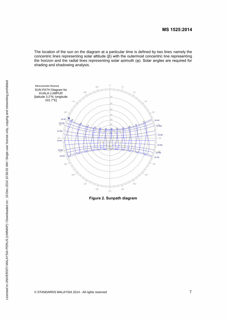
The designed DF may be obtained by simulation or architectural modeling of the building design. It is encouraged to model daylight performance by using scaled models or computer simulations, and the selected model conditions should be as close as possible to actual room conditions. 4.5 Facade design The facade of building is the external face of the building that encompasses the fenestration and other elements that describes the building form and aesthetics, enables indoor climatic control and provides security to occupants from weathering. A good facade design can help optimise daylighting and thermal comfort. The exterior wall and cladding systems should be designed to provide an integrated solution for the provision of view, daylight control, passive and active solar energy collection (e.g. building integrated photovoltaic, solar water heaters, ventilation systems, etc), and moisture management systems (e.g. dehumidifiers) while minimising heat gain. One of the most important aspects of façade design is sun-shading. The basic requirement is an understanding of the sun movement in relation to the site by studying the relevant sun path diagrams. The understanding of sun path diagram is also crucial for site planning and orientation as well as daylighting (refer 4.3 and 4.4). 4.5.1 Sun path diagram Sun path diagrams show the apparent path of the sun across the sky. The position of the sun in sky is defined by two angles: solar azimuth (φ) and solar altitude (β) as shown in Figure 1. Solar azimuth is the clockwise angle between the North reference and the perpendicular projection of the sun down onto the horizontal plane. Solar altitude or also referred to as solar elevation angle is angle of the sun’s position and the horizontal plane.
Figure 1. Solar angles Figure 2 is sun path diagram of Kuala Lumpur. The paths of the sun are represented by elliptical curves. The top elliptical curve represents the path of the sun for summer solstice (approximately Jun 21-22). The middle elliptical curve represents the path of the sun for March Equinox (approximately March 20-21) and September Equinox (approximately September 22-23.) The bottom elliptical curve represents the path of the sun for winter solstice (approximately December 21-22). The vertical curves indicate the location of the sun along the path at a particular time of the day in solar time.
Lice
nsed
to U
NIV
ER
SIT
I MA
LAY
SIA
PE
RLI
S (
UN
IMA
P)
/ Dow
nloa
ded
on :
10-D
ec-2
014
10:5
6:02
AM
/ S
ingl
e us
er li
cens
e on
ly, c
opyi
ng a
nd n
etw
orki
ng p
rohi
bite
d
MS 1525:2014
© STANDARDS MALAYSIA 2014 - All rights reserved 7
The location of the sun on the diagram at a particular time is defined by two lines namely the concentric lines representing solar altitude (β) with the outermost concentric line representing the horizon and the radial lines representing solar azimuth (φ). Solar angles are required for shading and shadowing analysis.
N15°
30°
45°
60°
75°
90°
105°
120°
135°
150°
165°180°
195°
210°
225°
240°
255°
270°
285°
300°
315°
330°
345°
10°
20°
30°
40°
50°
60°
70°
80°
8
910
111213141516
17
18
1920212223
1st Jan
1st Feb
1st Mar
1st Apr
1st May
1st Jun1st Jul
1st Aug
1st Sep
1st Oct
1st Nov
1st Dec
Stereographic Diagram Location: 3.2°, 101.7°
Figure 2. Sunpath diagram
SUN PATH Diagram for KUALA LUMPUR
[latitude 3.2°N, longitude 101.7°E]
Lice
nsed
to U
NIV
ER
SIT
I MA
LAY
SIA
PE
RLI
S (
UN
IMA
P)
/ Dow
nloa
ded
on :
10-D
ec-2
014
10:5
6:02
AM
/ S
ingl
e us
er li
cens
e on
ly, c
opyi
ng a
nd n
etw
orki
ng p
rohi
bite
d

MS 1525:2014
8 © STANDARDS MALAYSIA 2014 - All rights reserved
4.5.2 Sun-shading In determining the best sun-shading design, Shadow Angle Protractor can be superimposed on the sun path diagram to determine the Vertical Shadow Angle (VSA) and the Horizontal Shadow Angle (HSA). Figure 3 shows the superimposed Shadow Angle Protractor on the sun path diagram for Kuala Lumpur to determine VSA and HSA for North-East (NE) façade. For each façade the critical VSA and HSA need to be determined to design the appropriate sun-shading projections. Figure 4 illustrates the various solar angles (solar altitude and solar azimuth) and shadow angles (VSA and HSA) in relation to vertical and horizontal sun-shading
Figure 3. Superimposed shadow angle protractor on sun path diagram
a) Solar azimuth and Solar altitude
b) Altitude and HSA c) Solar altitude, HSA and VSA
Figure 4. Solar angles and shadow angles
Lice
nsed
to U
NIV
ER
SIT
I MA
LAY
SIA
PE
RLI
S (
UN
IMA
P)
/ Dow
nloa
ded
on :
10-D
ec-2
014
10:5
6:02
AM
/ S
ingl
e us
er li
cens
e on
ly, c
opyi
ng a
nd n
etw
orki
ng p
rohi
bite
d

MS 1525:2014
© STANDARDS MALAYSIA 2014 - All rights reserved 9
Table 2 presents shadow angle guidelines for preliminary design work. Various tools and softwares are now available to work out detailed sun-shading and overshadowing geometries.
Table 2. Shadow angle guidelines for Kuala Lumpur
Orientation VSA HSA Remarks (-) (+) N 65° 60° 60° Full shading
NE 35° - 20° Shading from 09:30 hr E 35° - - Shading from 09:00 hr
SE 30° 18° - Shading from 09:30 hr S 60° 55° 55° Full shading
SW 30° - 15° Shading until 17:00 hr W 35° - - Shading until 17:00 hr
NW 45° 15° - Full shading 4.6 Natural ventilation Natural ventilation uses natural forces of wind and buoyancy to deliver sufficient fresh air and air change to ventilate enclosed spaces without active temperature controls or mechanical means. Fresh air is required in buildings to alleviate odours and improve indoor environmental quality. Provisions for naturally ventilated lobby areas, corridors, lift cores, staircases should be encouraged. This could aid compliance to the requirements from the fire authorities for smoke venting of the spaces in the event of a fire. In some of these cases, spilled air from adjacent spaces is sufficient to provide for the required air change to ventilate the space and provide thermal comfort with reduced energy. Natural ventilation strategies rely on the movement of air through space to equalise pressure. There are basically two methods for providing natural ventilation: a) cross ventilation (wind-driven); and b) stack ventilation (buoyancy-driven). 4.6.1 Cross ventilation Good cross ventilation design should consider the following: a) orientate the building to maximise surface exposure to prevailing winds; b) provide inlets on the windward side (pressure zone) and outlets on the leeward side
(suction zone); c) use architectural features like wing walls and parapets to create positive and negative
pressure areas to induce cross ventilation; d) provide openings on opposite walls for optimum cross ventilation effectiveness. However,
if this is not possible, openings can be placed on adjacent walls; e) design openings to be easily accessible and operable by the occupants;
Lice
nsed
to U
NIV
ER
SIT
I MA
LAY
SIA
PE
RLI
S (
UN
IMA
P)
/ Dow
nloa
ded
on :
10-D
ec-2
014
10:5
6:02
AM
/ S
ingl
e us
er li
cens
e on
ly, c
opyi
ng a
nd n
etw
orki
ng p
rohi
bite
d

MS 1525:2014
10 © STANDARDS MALAYSIA 2014 - All rights reserved
f) avoid obstructions between inlets and outlets; g) have equal inlet and outlet areas to maximise airflow; h) design outlet openings to be slightly larger than inlet openings to produce higher air
velocities; i) locate outlet openings on the windward side at the occupied level; and j) use good site planning, landscaping and planting strategies to cool incoming air. 4.6.2 Stack ventilation A good stack ventilation should consider the following: a) provide at least two ventilation openings, one closer to the floor (inlet) and the other,
higher in the space (outlet); b) maximise the vertical distance between these two sets of openings. Increasing the
differential height will produce better airflow; c) provide equal inlet and outlet areas to maximise airflow; d) provide adequate openings in stairwells or other continuous vertical elements so that they
can work as stack wells. Such spaces may be used to ventilate adjacent spaces because their stack height allows them to displace large volumes of air;
e) use louvers on inlets to channel air intake; and f) use architectural features like solar chimneys to effectively exhaust the hot indoor air. The low incidence of significant wind force or low wind speeds to achieve sensible air movement for thermal comfort may necessitate additional air movement with the aid of mechanical means. 4.6.3 Air movement Air movement affects thermal comfort. The presence of air movement enhances evaporative and convective cooling from the skin and can further increase our thermal comfort. Table 3 provides a guide on the impact of air speed on occupants’ sensation.
Lice
nsed
to U
NIV
ER
SIT
I MA
LAY
SIA
PE
RLI
S (
UN
IMA
P)
/ Dow
nloa
ded
on :
10-D
ec-2
014
10:5
6:02
AM
/ S
ingl
e us
er li
cens
e on
ly, c
opyi
ng a
nd n
etw
orki
ng p
rohi
bite
d

MS 1525:2014
© STANDARDS MALAYSIA 2014 - All rights reserved 11
Table 3. Impact of air speed on occupants
Air speed (m/s)
Mechanical effect Occupant sensation
0.25 Smoke (from cigarette) indicates movement
Unnoticed, except at low air temperatures
0.25 - 0.5 Flame from a candle flickers Feels fresh at comfortable temperatures, but draughty at cool temperatures
0.5 - 1.0 Loose papers may be moved. Equivalent to walking speed
Generally pleasant when comfortable or warm, but causing constant awareness of air movement
1.0 - 1.5 Too fast for deskwork with loose papers
Acceptable in warm conditions but can be from slightly to annoyingly draughty
> 1.5 Equivalent to a fast walking speed
Acceptable only in very hot and humid conditions when no other relief is available. Requires corrective measures if comfort and productivity are to be maintained
4.6.4 Window design for daylighting and natural ventilation Windows form a fundamental component in a building’s facade. They provide a relationship between the exterior and interior in the form of light, sound, air and view of the exterior. The size, shape, position and orientation of windows are designed based on intended purposes and prioritised requirements. Table 4 is a guide for the design of windows.
Table 4. Window design
Purpose Design recommendation
Daylighting Optimum height and size for required daylight factor
Natural ventilation Orientation towards prevailing wind direction
Daylighting and view Size and sill height suited to occupant position and external features
Daylighting and natural ventilation
Size and location should be suited to all parameters
4.7 Thermal insulation
Thermal insulation and thermal mass can play an important role to reduce solar heat gain for passive cooling and decrease energy demand for active cooling of the building interior. Thermal insulation in buildings can be categorised as ‘bulk’ or ‘resistive insulation’ and ‘reflective insulation’. Bulk insulation (e.g. mineral wool) is normally used for thermal insulation in walls and roofs, as well as for noise-dampening under a metal roof. It works on the principle of retarding heat transfer due to the properties of low thermal conductivity (k-value) or high thermal resistance (R-value).
Lice
nsed
to U
NIV
ER
SIT
I MA
LAY
SIA
PE
RLI
S (
UN
IMA
P)
/ Dow
nloa
ded
on :
10-D
ec-2
014
10:5
6:02
AM
/ S
ingl
e us
er li
cens
e on
ly, c
opyi
ng a
nd n
etw
orki
ng p
rohi
bite
d
MS 1525:2014
12 © STANDARDS MALAYSIA 2014 - All rights reserved
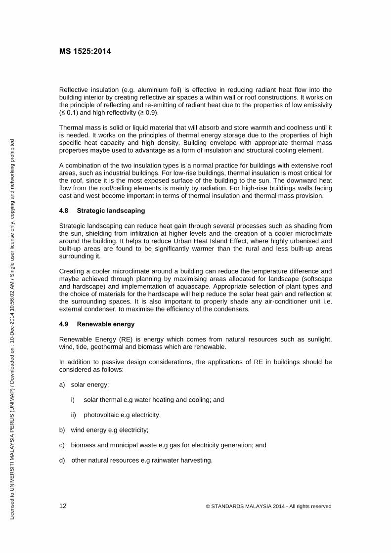
Reflective insulation (e.g. aluminium foil) is effective in reducing radiant heat flow into the building interior by creating reflective air spaces a within wall or roof constructions. It works on the principle of reflecting and re-emitting of radiant heat due to the properties of low emissivity (≤ 0.1) and high reflectivity (≥ 0.9). Thermal mass is solid or liquid material that will absorb and store warmth and coolness until it is needed. It works on the principles of thermal energy storage due to the properties of high specific heat capacity and high density. Building envelope with appropriate thermal mass properties maybe used to advantage as a form of insulation and structural cooling element. A combination of the two insulation types is a normal practice for buildings with extensive roof areas, such as industrial buildings. For low-rise buildings, thermal insulation is most critical for the roof, since it is the most exposed surface of the building to the sun. The downward heat flow from the roof/ceiling elements is mainly by radiation. For high-rise buildings walls facing east and west become important in terms of thermal insulation and thermal mass provision. 4.8 Strategic landscaping Strategic landscaping can reduce heat gain through several processes such as shading from the sun, shielding from infiltration at higher levels and the creation of a cooler microclimate around the building. It helps to reduce Urban Heat Island Effect, where highly urbanised and built-up areas are found to be significantly warmer than the rural and less built-up areas surrounding it. Creating a cooler microclimate around a building can reduce the temperature difference and maybe achieved through planning by maximising areas allocated for landscape (softscape and hardscape) and implementation of aquascape. Appropriate selection of plant types and the choice of materials for the hardscape will help reduce the solar heat gain and reflection at the surrounding spaces. It is also important to properly shade any air-conditioner unit i.e. external condenser, to maximise the efficiency of the condensers. 4.9 Renewable energy Renewable Energy (RE) is energy which comes from natural resources such as sunlight, wind, tide, geothermal and biomass which are renewable. In addition to passive design considerations, the applications of RE in buildings should be considered as follows: a) solar energy;
i) solar thermal e.g water heating and cooling; and ii) photovoltaic e.g electricity.
b) wind energy e.g electricity; c) biomass and municipal waste e.g gas for electricity generation; and
d) other natural resources e.g rainwater harvesting.
Lice
nsed
to U
NIV
ER
SIT
I MA
LAY
SIA
PE
RLI
S (
UN
IMA
P)
/ Dow
nloa
ded
on :
10-D
ec-2
014
10:5
6:02
AM
/ S
ingl
e us
er li
cens
e on
ly, c
opyi
ng a
nd n
etw
orki
ng p
rohi
bite
d

MS 1525:2014
© STANDARDS MALAYSIA 2014 - All rights reserved 13
The decision to apply RE systems in a building shall be made at the design and planning stage. The selection of the most suitable RE option should be based on the microclimatic conditions and the availability of the natural resources. Rain water harvesting should also be considered to be integrated into building and/or part of any befitting renewable energy systems. The design solutions for the selected option/s should ensure the effectiveness of the operation to optimise the efficiency of the system. 4.10 Other considerations In addition to the above, the following aspects should be considered: overall site master planning, the building’s internal design such as effective room depth, floor to ceiling height, location of cores, internal layout, building materials and roof design and colour.
5 Building envelope 5.1 General requirement Fundamentally, the building envelope has to block out heat gain into buildings via conduction and solar radiation. Simulation studies indicate that heat may be conducted both in and out of the building depending on the time of the day. This is especially so, for a typical office buildings that are air-conditioned during daytime only - heat would be conducted into the buildings during daytime and heat would be conducted out of the building during night time (especially during early morning hours when external temperatures are low). This phenomenon occurs in buildings that have high internal load at night. Internal loads are caused by lightings and equipments that are kept running during night time and these would generate heat within the building. It is therefore important that energy management is well conducted to ensure that night time internal load is kept to the minimum, to ensure that maximum benefit would be derived from the insulation of the building envelope. An alternative to complying with this clause is available in Clause 10, Building Energy Simulation Method. The Building Energy Simulation Method, allows designer to prove compliance by the same method used to derive the OTTV constants. In addition, Clause 10 applies the whole-building energy efficiency concept, and credits are accepted for on-site renewable energy sources, improved ACMV and daylight use. 5.2 Concept of OTTV The solar heat gain through the building envelope constitutes a substantial share of cooling load in an air-conditioned building. In non air-conditioned buildings, the solar heat gain causes thermal discomfort. To minimise solar heat gain into a building is, therefore, a very important consideration in the design of an energy efficient building. A design criterion for building envelope known as the overall thermal transfer value (OTTV) has been adopted. The OTTV requirement is simple, and was developed for air-conditioned building. It is also a useful indicator for non air-conditioned buildings. The OTTV aims at achieving the design of building envelope to cut down external heat gain and hence reduce the cooling load of the air-conditioning system. The OTTV of the building envelope for a building, having a total air-conditioned area exceeding 1000 m2 should not exceed 50 W/m2 and should meet the requirement specified in 5.4.2.
Lice
nsed
to U
NIV
ER
SIT
I MA
LAY
SIA
PE
RLI
S (
UN
IMA
P)
/ Dow
nloa
ded
on :
10-D
ec-2
014
10:5
6:02
AM
/ S
ingl
e us
er li
cens
e on
ly, c
opyi
ng a
nd n
etw
orki
ng p
rohi
bite
d
MS 1525:2014
14 © STANDARDS MALAYSIA 2014 - All rights reserved
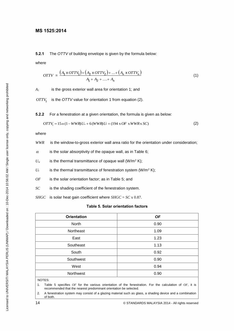
5.2.1 The OTTV of building envelope is given by the formula below: where
OTTV =
n
nn
A....AA
OTTV A...OTTV AOTTV A
21
2211 xxx (1)
A1 is the gross exterior wall area for orientation 1; and
1OTTV is the OTTV value for orientation 1 from equation (2).
5.2.2 For a fenestration at a given orientation, the formula is given as below:
) x x x (194)(6)(115 fwi SCWWROFUWWRUWWRαOTTV
(2)
where WWR is the window-to-gross exterior wall area ratio for the orientation under consideration;
α is the solar absorptivity of the opaque wall, as in Table 6;
Uw is the thermal transmittance of opaque wall (W/m2 K); Uf is the thermal transmittance of fenestration system (W/m2 K); OF is the solar orientation factor; as in Table 5; and SC is the shading coefficient of the fenestration system. SHGC is solar heat gain coefficient where SHGC = SC x 0.87.
Table 5. Solar orientation factors
Orientation OF
North 0.90
Northeast 1.09
East 1.23
Southeast 1.13
South 0.92
Southwest 0.90
West 0.94
Northwest 0.90
NOTES:
1. Table 5 specifies OF for the various orientation of the fenestration. For the calculation of OF, it is recommended that the nearest predominant orientation be selected.
2. A fenestration system may consist of a glazing material such as glass, a shading device and a combination of both.
Lice
nsed
to U
NIV
ER
SIT
I MA
LAY
SIA
PE
RLI
S (
UN
IMA
P)
/ Dow
nloa
ded
on :
10-D
ec-2
014
10:5
6:02
AM
/ S
ingl
e us
er li
cens
e on
ly, c
opyi
ng a
nd n
etw
orki
ng p
rohi
bite
d

MS 1525:2014
© STANDARDS MALAYSIA 2014 - All rights reserved 15
Table 6. Solar absorbtivity
NOTE. Table 5 and Table 6 is based on updated (2006) data to match with the current test reference year (TRY) weather data for Kuala Lumpur. Data collected indicates that the average vertical East surface solar radiation is significantly higher than the vertical West surface. This trend is seen to be caused by the normally clear sky in the morning and cloudy sky in the afternoon.
5.3 Shading coefficient 5.3.1 The shading coefficient of a shading system is the product of the shading coefficients of its sub-systems, for example
SC = SC1 x SC2 (3) where SC is the effective shading coefficient of the fenestration system; SC1 is the shading coefficient of sub-system 1 (e.g. glass); and
SC2 is the shading coefficient of sub-system 2 (e.g. external shading devices).
5.3.2 The shading coefficient for glass is the value assessed at normal incident angle. 5.3.3 The shading coefficient of external shading devices can be obtained from following Figures 5, 6, 7 and 8.
Colour Suggested value of α
Light < 0.40
Medium 0.40 to 0.70
Dark > 0.70
Lice
nsed
to U
NIV
ER
SIT
I MA
LAY
SIA
PE
RLI
S (
UN
IMA
P)
/ Dow
nloa
ded
on :
10-D
ec-2
014
10:5
6:02
AM
/ S
ingl
e us
er li
cens
e on
ly, c
opyi
ng a
nd n
etw
orki
ng p
rohi
bite
d

HORIZONTAL PROJECTION SHADING COFFICIENTS
0.5
0.55
0.6
0.65
0.7
0.75
0.8
0.85
R1 (Projection / Window Height)
Shad
ing
Coef
ficie
nt
North/South 0.77 0.71 0.67 0.65
East 0.77 0.68 0.6 0.55
West 0.79 0.71 0.65 0.61
NE/SW 0.77 0.69 0.63 0.6
NW/SE 0.79 0.72 0.66 0.63
0,35 0.6 1 1.65
SHADING COFFICIENTS HORIZONTAL PROJECTIONS
R1 0.3 to 0.4 0.5 to 0.7 0.8 to 1.2 1.3 to 2.0 North/South 0.77 0.71 0.67 0.65
East 0.77 0.68 0.6 0.55
West 0.79 0.71 0.65 0.61
NE/SW 0.77 0.69 0.63 0.6
NW/SE 0.79 0.72 0.66 0.63
Figure 5. Horizontal projection shading coefficients
MS 1525:2014
16
©
ST
AN
DA
RD
S M
ALA
YS
IA 2
014 - A
ll rights
reserv
ed
Lice
nsed
to U
NIV
ER
SIT
I MA
LAY
SIA
PE
RLI
S (
UN
IMA
P)
/ Dow
nloa
ded
on :
10-D
ec-2
014
10:5
6:02
AM
/ S
ingl
e us
er li
cens
e on
ly, c
opyi
ng a
nd n
etw
orki
ng p
rohi
bite
d

Figure 6. Vertical projection shading coefficients
VERTICAL PROJECTIONS SHADING COFFICIENTS
R2 0.3 to 0.4 0.5 to 0.7 0.8 to 0.12 1.3 to 2.0
North/South 0.82 0.77 0.73 0.7
East 0.87 0.82 0.78 0.75
West 0.86 0.81 0.77 0.74
NE/SW 0.83 0.77 0.72 0.69
NW/SE 0.84 0.79 0.74 0.71
MS 1525:2014
© S
TA
ND
AR
DS
MA
LA
YS
IA 2
014 - A
ll rights
reserv
ed
17
Lice
nsed
to U
NIV
ER
SIT
I MA
LAY
SIA
PE
RLI
S (
UN
IMA
P)
/ Dow
nloa
ded
on :
10-D
ec-2
014
10:5
6:02
AM
/ S
ingl
e us
er li
cens
e on
ly, c
opyi
ng a
nd n
etw
orki
ng p
rohi
bite
d

Figure 7. Egg crate shading coefficients
EGG CRATE SHADING COFFICIENTS
R1&R2 R1=0.2 R2=0.2
R1=0.2 R2=0.4-0.6
R1=0.2 R2=0.6-0.8
R1=0.4 R2=0.2-0.4
R1=0.4 R2=0.6-1.2
R1=0.4 R2=1.4-1.8
R1=0.6 R2=0.2-0.6
R1=0.6 R2=0.8-1.8
R1=0.8 R2=0.2-0.6
R1=0.8 R2=0.8-1.8
R1=1 R2=0.2-0.4
R1=1 R2=0.6-1.2
R1=1 R2=1.4-1.8
R1=1 2-1.8 R2=0.2-1.8
North/South 0.71 0.62 0.56 0.59 0.49 0.46 0.52 0.43 0.5 0.4 0.51 0.41 0.38 0.38
East 0.77 0.69 0.62 0.63 0.54 0.5 0.54 0.44 0.49 0.39 0.48 0.39 0.35 0.35
West 0.77 0.69 0.61 0.64 0.54 0.51 0.56 0.46 0.52 0.42 0.52 0.42 0.38 0.38
NE/SW 0.73 0.63 0.55 0.6 0.48 0.44 0.51 0.39 0.47 0.36 0.48 0.36 0.32 0.32
NW/SE 0.75 0.66 0.58 0.63 0.52 0.48 0.55 0.44 0.52 0.41 0.52 0.42 0.38 0.38
MS 1525:2014
18
© S
TA
ND
AR
DS
MA
LA
YS
IA 2
014 - A
ll rights
reserv
ed
Lice
nsed
to U
NIV
ER
SIT
I MA
LAY
SIA
PE
RLI
S (
UN
IMA
P)
/ Dow
nloa
ded
on :
10-D
ec-2
014
10:5
6:02
AM
/ S
ingl
e us
er li
cens
e on
ly, c
opyi
ng a
nd n
etw
orki
ng p
rohi
bite
d

R1 = Proj/Window Height R2 = Proj/Window Width
Figure 8. Egg Crate Shading Coefficients
EGG CRATE SHADING COFFICIENTS
R1 0.20 0.20 0.20 0.40 0.40 0.40 0.60 0.60 0.80 0.80 1.00 1.00 1.00 1.2 to 1.8
R2 0.20 0.4 to 0.6 0.6 to 0.8 0.2 to 0.4 0.6 to 1.2 1.4 to 1.8 0.2 to 0.6 0.8 to 1.8 0.2 to 0.6 0.8 to 1.8 0.2 to 0.4 0.6 to 1.2 1.4 to 1.8 0.2 to 1.8
North/South 0.71 0.62 0.56 0.59 0.49 0.46 0.52 0.43 0.5 0.4 0.51 0.41 0.38 0.38
East 0.77 0.69 0.62 0.63 0.54 0.5 0.54 0.44 0.49 0.39 0.48 0.39 0.35 0.33
West 0.77 0.69 0.61 0.64 0.54 0.51 0.56 0.46 0.52 0.42 0.52 0.42 0.38 0.38
NE/SW 0.73 0.63 0.55 0.6 0.48 0.44 0.51 0.39 0.47 0.36 0.48 0.36 0.32 0.32
NW/SE 0.75 0.66 0.58 0.63 0.52 0.48 0.55 0.44 0.52 0.41 0.52 0.42 0.38 0.38
MS 1525:2014
© S
TA
ND
AR
DS
MA
LA
YS
IA 2
014 - A
ll rights
reserv
ed
19
Lice
nsed
to U
NIV
ER
SIT
I MA
LAY
SIA
PE
RLI
S (
UN
IMA
P)
/ Dow
nloa
ded
on :
10-D
ec-2
014
10:5
6:02
AM
/ S
ingl
e us
er li
cens
e on
ly, c
opyi
ng a
nd n
etw
orki
ng p
rohi
bite
d

MS 1525:2014
20 © STANDARDS MALAYSIA 2014 - All rights reserved
11D062R
2
5.4 Daylighting 5.4.1 Saving in energy consumption for lighting due to daylighting technique is greater than the cooling energy penalties from additional glazed surface provided that the building envelope is carefully designed for daylighting. Fenestration for the purpose of daylighting should be designed to prevent direct solar radiation while allowing diffused light for effective daylighting. The recommended range of daylight factor is 1.0 % to 3.5 %. 5.4.2 In order to take advantage of daylight harvesting, the visible light transmission of the daylight fenestration system should not be less than 30 %. Alternative compliance is to provide lighting simulation study showing daylight factor of 1 % at a minimum depth of 3 m from the facade building. This simulation study should have glare protection devices in place. The glare protection devices should limit the luminance intensity of the daylight fenestration to a value less than 2,000 cd/m² at the worst case condition with direct sunlight impacting on the daylight fenestration. 5.5 Roofs 5.5.1 The roof of a conditioned space shall not have a thermal transmittance (U-value) greater than that tabulated in Table 7.
Table 7. Maximum U-value for roof (W/m²K)
Roof Weight Group
Maximum U-Value (W/m²K)
Light
(Under 50 kg/m²)
0.4
Heavy
(Above 50 kg/m²)
0.6
5.5.2 If more than one type of roof is used, the average thermal transmittance for the gross area of the roof shall be determined from:
Ur =
nr rr
nr nr rrrr
A...AA
U A...U AU A
21
2211 xxx (4)
where Ur is the average thermal transmittance of the gross area (W/m2 K); U r1 is the respective thermal transmittance of different roof sections (W/m2 K); and A r1 is the respective area of different roof sections (m²).
Lice
nsed
to U
NIV
ER
SIT
I MA
LAY
SIA
PE
RLI
S (
UN
IMA
P)
/ Dow
nloa
ded
on :
10-D
ec-2
014
10:5
6:02
AM
/ S
ingl
e us
er li
cens
e on
ly, c
opyi
ng a
nd n
etw
orki
ng p
rohi
bite
d

MS 1525:2014
© STANDARDS MALAYSIA 2014 - All rights reserved 21
11D062R
2
The average weight of the roof is calculated as follows:
Wr =
nr rr
nr n r rrrr
A....AA
W A....W AW A
21
2211 xxx (5)
where, Wr is the average weight of roof (kg/m2); Ar1 is the respective area of different roof sections (m²); and Wra is the respective weight of different roof sections (kg/m2). 5.6 Roofs with skylights 5.6.1 Concept of roof thermal transfer value (RTTV) In the case of an air-conditioned building, the concept of Roof Thermal Transfer Value (RTTV) is applied if the roof is provided with skylight and the entire enclosure below is fully air-conditioned. 5.6.2 For roofs with skylight, in addition to the requirement of 5.5.1 the maximum recommended RTTV is 25 W/m2. 5.6.3 The RTTV of roof is given by the following equation.
RTTV =
0
Deqrr sss
A
SF SC ATU ATU A xx x x x x
(6)
where RTTV is the roof thermal transfer value (W/m2); Ar is the opaque roof area (m2); Ur is the thermal transmittance of opaque roof area (W/m2 K); TDeq is the equivalent temperature difference (K), as from Table 8; As is the skylight area (m2); Us is the thermal transmittance of skylight area (W/m2);
T is the temperature difference between exterior and interior design conditions (5 K); SC is the shading coefficient of skylight; SF is the solar factor (W/m2), see 5.6.5; and Ao is the gross roof area (m2) where Ao = Ar + As.
Lice
nsed
to U
NIV
ER
SIT
I MA
LAY
SIA
PE
RLI
S (
UN
IMA
P)
/ Dow
nloa
ded
on :
10-D
ec-2
014
10:5
6:02
AM
/ S
ingl
e us
er li
cens
e on
ly, c
opyi
ng a
nd n
etw
orki
ng p
rohi
bite
d
MS 1525:2014
22 © STANDARDS MALAYSIA 2014 - All rights reserved
11D062R
2
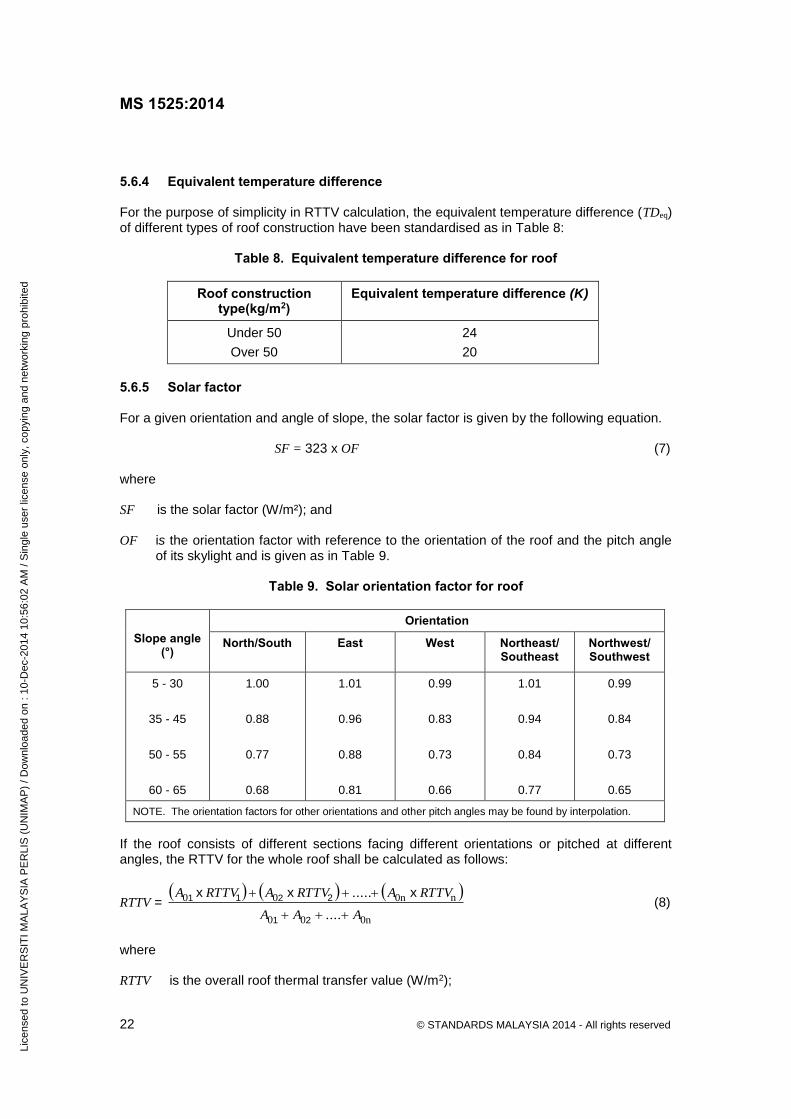
5.6.4 Equivalent temperature difference For the purpose of simplicity in RTTV calculation, the equivalent temperature difference (TDeq) of different types of roof construction have been standardised as in Table 8:
Table 8. Equivalent temperature difference for roof
Roof construction type(kg/m2)
Equivalent temperature difference (K)
Under 50
Over 50
24
20
5.6.5 Solar factor For a given orientation and angle of slope, the solar factor is given by the following equation.
SF = 323 x OF (7)
where SF is the solar factor (W/m²); and OF is the orientation factor with reference to the orientation of the roof and the pitch angle
of its skylight and is given as in Table 9.
Table 9. Solar orientation factor for roof
Slope angle
(°)
Orientation
North/South
East West Northeast/ Southeast
Northwest/ Southwest
5 - 30
35 - 45
50 - 55
60 - 65
1.00
0.88
0.77
0.68
1.01
0.96
0.88
0.81
0.99
0.83
0.73
0.66
1.01
0.94
0.84
0.77
0.99
0.84
0.73
0.65
NOTE. The orientation factors for other orientations and other pitch angles may be found by interpolation.
If the roof consists of different sections facing different orientations or pitched at different angles, the RTTV for the whole roof shall be calculated as follows:
RTTV =
0n00
n0n00
A....AA
RTTV A.....RTTV ARTTV A
21
2211 xxx (8)
where RTTV is the overall roof thermal transfer value (W/m2);
Lice
nsed
to U
NIV
ER
SIT
I MA
LAY
SIA
PE
RLI
S (
UN
IMA
P)
/ Dow
nloa
ded
on :
10-D
ec-2
014
10:5
6:02
AM
/ S
ingl
e us
er li
cens
e on
ly, c
opyi
ng a
nd n
etw
orki
ng p
rohi
bite
d
MS 1525:2014
© STANDARDS MALAYSIA 2014 - All rights reserved 23
11D062R
2
A0i is the respective area of different roof sections (m2); and RTTVi is the respective roof thermal transfer value of different roof sections (W/m2). 5.6.6 The gross roof area shall include all opaque roof areas and skylight areas, when such surfaces are exposed to outdoor air and enclose an air conditioned space. 5.7 Submission procedure The following information shall be provided by a professional architect or professional engineer: a) a drawing showing the cross-sections of typical parts of the roof construction, giving
details of the type and thickness of basic construction materials, insulation and air space; b) the U-value of the roof assembly; c) the OTTV calculation; and d) the RTTV of the roof assembly, if provided with skylights. 5.8 Air leakage 5.8.1 General requirement The building envelope should provide adequate barrier to prevent uncontrolled mixing of outside air with air-conditioned space. NOTE. The energy required to remove moisture from uncontrolled leakages of outside air into the building is one of the highest energy load contributed by the external environment into a building in the tropical climate. In a leaky building, the energy used to remove moisture would be higher than the energy used to remove heat contributed by solar radiation.
5.8.2 All open-able fenestration and doors between conditioned space and non-conditioned space should have an advisory label on it requesting that fenestration and doors are to be kept closed when not in use. 5.8.3 Any duct that provides a connection between conditioned space to outside air should have a damper in between to prevent air leakages into conditioned space when the duct is not in operation. 5.8.4 Where the false ceiling is used as return air plenum to the AHU (air handling unit); partitions should be placed in the false ceiling space between conditioned space and naturally ventilated space to prevent air leakages. 5.8.5 Vestibules It is recommended that a door that separates conditioned space from the exterior is protected by an enclosed vestibule, with all doors opening into and out of the vestibule equipped with self-closing devices. Vestibules should be designed so that in passing through the vestibule it is not necessary for the interior and exterior doors to open at the same time. Interior and exterior doors should have a minimum distance between them of not less than 2.5 meters when in closed position.
Lice
nsed
to U
NIV
ER
SIT
I MA
LAY
SIA
PE
RLI
S (
UN
IMA
P)
/ Dow
nloa
ded
on :
10-D
ec-2
014
10:5
6:02
AM
/ S
ingl
e us
er li
cens
e on
ly, c
opyi
ng a
nd n
etw
orki
ng p
rohi
bite
d

MS 1525:2014
24 © STANDARDS MALAYSIA 2014 - All rights reserved
11D062R
2
Exceptions to 5.8.5 can be made in the following cases: a) doors in buildings less than four stories above ground; b) doors are not intended to be used as a building entrance door, such as mechanical or
electrical equipment rooms; c) doors opening directly from a residential unit; d) doors that open directly from a space less than 300 sq meter in area; e) doors in building entrances with revolving doors; and f) doors used in primarily to facilitate vehicular movement or material handling and adjacent
personnel doors. 5.8.6 It is recommended that the following areas of the building envelope be sealed, caulked, gasketed, or weather-stripped to minimise air leakage: a) joints around fenestration and door frames; b) junctions between walls and foundations, between walls at building corners, between
walls and structural floors or roofs, and between walls and roof or wall panels; c) openings at penetrations of utility services through roofs, walls and floors; d) site-built fenestration and doors; e) building assemblies used as ducts or plenums; f) joints, seams, and penetrations of vapor retarders; and g) all other openings in the building envelope surrounding conditioned space. 5.8.7 The above, shall not reduce the outside air ventilation rate as specified in 8.1.4.
6 Lighting 6.1 Introduction The compliance to this clause requires the compliance to MS ISO 8995 (which is the minimum safety standard for interior lighting) and MS 825 (which is the minimum safety standard for exterior spaces). 6.1.1 Applications excluded from this clause include: a) outdoor activities such as manufacturing, storage, commercial greenhouse and
processing facilities; b) lighting power for theatrical productions, television broadcasting, audio-visual
presentations and those portions of entertainment facilities such as stage areas in hotel ballrooms, night-clubs, discos and casinos where lighting is an essential technical element for the function performed;
Lice
nsed
to U
NIV
ER
SIT
I MA
LAY
SIA
PE
RLI
S (
UN
IMA
P)
/ Dow
nloa
ded
on :
10-D
ec-2
014
10:5
6:02
AM
/ S
ingl
e us
er li
cens
e on
ly, c
opyi
ng a
nd n
etw
orki
ng p
rohi
bite
d
MS 1525:2014
© STANDARDS MALAYSIA 2014 - All rights reserved 25
11D062R
2
c) specialised luminaires for medical and dental purposes; d) outdoor recreational facilities; e) display lighting required for art exhibition or display in galleries, museums and
monuments; f) exterior lighting for public monuments; g) special lighting needs for research laboratories; h) lighting to be used solely for lighting indoor and outdoor plant growth during the hours of
10.00 pm and 6.00 am; i) emergency lighting that is automatically ‘off’ during normal operations; j) high risk security areas identified by local ordinances or regulations or by security or
safety personnel requiring additional lighting;
k) lighting for signs; and
l) store-front display windows in retail facilities. 6.2 General principles of efficient lighting practice 6.2.1 Lighting shall provide a suitable visual environment within a particular space i.e. sufficient and suitable lighting for the performance of a range of tasks and provision of a desired appearance. The prescribed colour rendering index (CRI) for a particular task application should also be considered in conjunction with the illuminance level.
6.2.2 The maintained illuminance levels with corresponding CRI for general building areas are as given in Table 10.
Lice
nsed
to U
NIV
ER
SIT
I MA
LAY
SIA
PE
RLI
S (
UN
IMA
P)
/ Dow
nloa
ded
on :
10-D
ec-2
014
10:5
6:02
AM
/ S
ingl
e us
er li
cens
e on
ly, c
opyi
ng a
nd n
etw
orki
ng p
rohi
bite
d

MS 1525:2014
26 © STANDARDS MALAYSIA 2014 - All rights reserved
11D062R
2
Table 10. Recommended average illuminance levels
Task and Applications Illuminance (Lux)
Minimum CRI
a) Lighting for infrequently used area:
- Minimum service illuminance 20 30
- Interior walkway and car-park 100 40
- Hotel bedroom 100 60
- Lift interior 100 40
- Corridor, passageways, stairs 100 40
- Escalator, travellator 150 40
- Entrance and exit 100 60
- Staff changing room, locker and cleaner room, cloak room, lavatories, stores.
100 60
- Entrance hall, lobbies, waiting room 100 60
- Inquiry desk 300 80
- Gate house 200 80
b) Lighting for working interiors
- Infrequent reading and writing 200 80
- General offices, shops and stores, reading and writing
300 - 400 80
- Drawing office 300 - 400 85
- Restroom 150 80
- Restaurant, canteen, cafeteria 200 80
- Kitchen 150 - 300 80
- Lounge 150 60
- Bathroom 150 80
- Toilet 100 60
- Bedroom 100 80
- Class room, library 300 - 500 80
- Shop/supermarket/department store 200 - 750 80
- Museum and gallery 300 80
c) Localised lighting for exacting task
- Proof reading 500 80
- Exacting drawing 1000 80
- Detailed and precise work 2000 80
Lice
nsed
to U
NIV
ER
SIT
I MA
LAY
SIA
PE
RLI
S (
UN
IMA
P)
/ Dow
nloa
ded
on :
10-D
ec-2
014
10:5
6:02
AM
/ S
ingl
e us
er li
cens
e on
ly, c
opyi
ng a
nd n
etw
orki
ng p
rohi
bite
d

MS 1525:2014
© STANDARDS MALAYSIA 2014 - All rights reserved 27
11D062R
2
6.2.3 Installed power and energy consumption should be minimised by the use of more efficient lamp/ballast systems and luminaires. 6.2.4 Where discharge lamps are used, ballast loss shall not exceed the values in Table 10a.
Table 10a. Recommended Loss Values for Ballast
No Lamp Type Maximum Allowable Losses
1 Fluorescent lamps, compact fluorescent 4 W
2 Sodium 70 W 15 W
3 Sodium 100 W 20 W
4 Sodium 150 W 22 W
5 Sodium 250 W 30 W
6 Sodium 400 W 45 W
7 Metal Halide 70 W 16 W
8 Metal Halide 100 W 16 W
9 Metal Halide 150 W 20 W
10 Metal Halide 250 W 34 W
11 Metal Halide 400 W 40 W
12 Metal Halide 1000 W 60 W
13 Mercury 80 W 12 W
14 Mercury 125 W 15 W
15 Mercury 250 W 18 W
16 Mercury 400 W 28 W
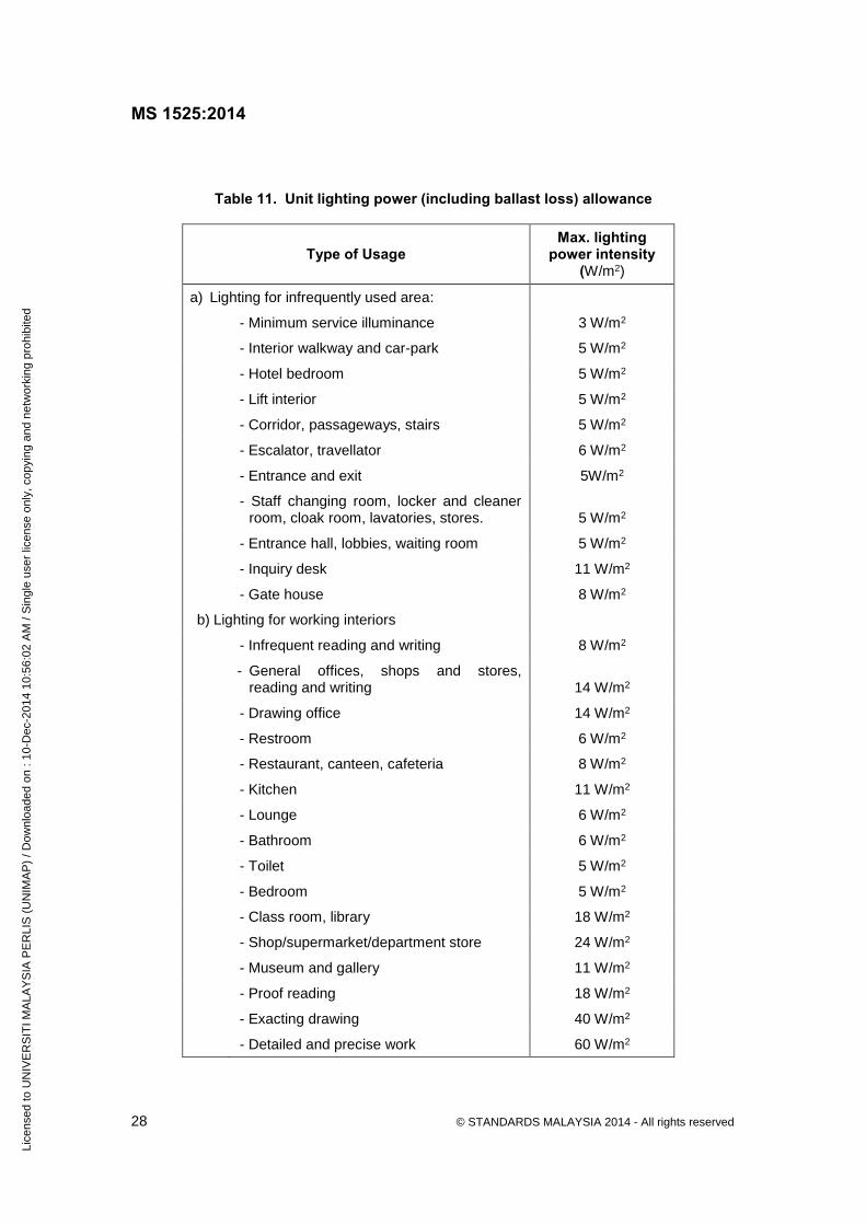
6.2.5 Luminaires shall be selected for efficient distribution of light without producing discomfort glare. 6.3 Maximum allowable power intensity for illumination systems Lighting load shall not exceed the corresponding maximum power intensity value as specified in Table 11. For Table 11 assumes power intensity to include ballast losses, luminaire performances and all requirements for compliance to minimum safety standards as prescribed in 6.1.
Lice
nsed
to U
NIV
ER
SIT
I MA
LAY
SIA
PE
RLI
S (
UN
IMA
P)
/ Dow
nloa
ded
on :
10-D
ec-2
014
10:5
6:02
AM
/ S
ingl
e us
er li
cens
e on
ly, c
opyi
ng a
nd n
etw
orki
ng p
rohi
bite
d
MS 1525:2014
28 © STANDARDS MALAYSIA 2014 - All rights reserved
11D062R
2
Table 11. Unit lighting power (including ballast loss) allowance
Type of Usage Max. lighting
power intensity (W/m2)
a) Lighting for infrequently used area:
- Minimum service illuminance 3 W/m2
- Interior walkway and car-park 5 W/m2
- Hotel bedroom 5 W/m2
- Lift interior 5 W/m2
- Corridor, passageways, stairs 5 W/m2
- Escalator, travellator 6 W/m2
- Entrance and exit 5W/m2
- Staff changing room, locker and cleaner room, cloak room, lavatories, stores.
5 W/m2
- Entrance hall, lobbies, waiting room 5 W/m2
- Inquiry desk 11 W/m2
- Gate house 8 W/m2
b) Lighting for working interiors
- Infrequent reading and writing 8 W/m2
- General offices, shops and stores, reading and writing
14 W/m2
- Drawing office 14 W/m2
- Restroom 6 W/m2
- Restaurant, canteen, cafeteria 8 W/m2
- Kitchen 11 W/m2
- Lounge 6 W/m2
- Bathroom 6 W/m2
- Toilet 5 W/m2
- Bedroom 5 W/m2
- Class room, library 18 W/m2
- Shop/supermarket/department store 24 W/m2
- Museum and gallery 11 W/m2
- Proof reading 18 W/m2
- Exacting drawing 40 W/m2
- Detailed and precise work 60 W/m2
Lice
nsed
to U
NIV
ER
SIT
I MA
LAY
SIA
PE
RLI
S (
UN
IMA
P)
/ Dow
nloa
ded
on :
10-D
ec-2
014
10:5
6:02
AM
/ S
ingl
e us
er li
cens
e on
ly, c
opyi
ng a
nd n
etw
orki
ng p
rohi
bite
d

MS 1525:2014
© STANDARDS MALAYSIA 2014 - All rights reserved 29
11D062R
2
6.4 Exterior building lighting power requirements 6.4.1 The same lighting systems criteria specified in 6.3 should apply. 6.4.2 The lighting power load for external car parks, drive-ways, pedestrian malls, landscape areas, shall not exceed the power intensities in Table 12. The area shall be the net site area excluding the built-up area.
Table 12. Building exteriors maximum lighting power intensity allowance
Building Exteriors Max. lighting power intensity
(W/m2)
Uncovered parking areas 2
Uncovered driveways 2
Pedestrian malls 5
Landscape areas 5
6.4.3 For facilities with multiple buildings, the building exterior lighting power requirements may be traded off among the buildings.
6.5 Lighting controls 6.5.1 All lighting systems except those required for emergency or exit lighting should be provided with manual, automatic or programmable controls. For lighting loads exceeding 100 kW automatic control should be provided. 6.5.2 Lighting zones control for daylight energy savings scheme. The minimum number of lighting control for daylight energy savings scheme should take into consideration the following criteria:
a) all spaces enclosed by walls or ceiling height partitions should be provided with at least one operated-on-off lighting control for each room;
b) one switch is provided for each task or group of tasks within an area of 30 m2 or less; c) the total number of switches should be at least one switch for each 1 kW of connected
load; and d) availability of lighting zones control for energy saving.
6.5.3 Switches provided for task areas, if readily accessible may be mounted as part of the task lighting fixtures. Switches controlling the same load from more than one location should not be credited as increasing the number of controls to meet the requirements of this subclause. 6.5.4 Lighting control requirements for spaces which are used as a whole (such as public lobbies of office buildings, hotels and hospitals, retail and department stores and service corridors under centralised supervision) should be controlled in accordance with the work activities, and controls may be centralised in remote locations.
Lice
nsed
to U
NIV
ER
SIT
I MA
LAY
SIA
PE
RLI
S (
UN
IMA
P)
/ Dow
nloa
ded
on :
10-D
ec-2
014
10:5
6:02
AM
/ S
ingl
e us
er li
cens
e on
ly, c
opyi
ng a
nd n
etw
orki
ng p
rohi
bite
d
MS 1525:2014
30 © STANDARDS MALAYSIA 2014 - All rights reserved
11D062R
2
6.6 Control accessibility 6.6.1 All lighting controls should be located at an accessible place with the following exceptions: a) lighting control requirements for spaces which shall be used as a whole, such as public
lobbies of office buildings, hotels and hospital, retail and department stores and service corridors under centralised supervision should be controlled in accordance with the work activities, and controls may be centralised in remote locations;
b) automatic controls; c) programmable controls; d) controls requiring trained operators; and e) controls for safety hazards and security. 6.6.2 Hotel and motel guest rooms should have a master switch which automatically turns off all lighting, power outlets and reduce operating air-conditioning loads except for essential loads. 6.6.3 Exterior lighting not intended for 24 hour continuous use should be automatically switched by timer and/or photocell. 6.6.4 Local manual controls or automatic controls such as photoelectric switches or automatic dimmers should be provided in day lighted space. Controls should be provided so as to operate rows of light parallel to the facade/exterior wall. 6.7 Operation and maintenance (O and M) manual and as built drawing An operation and maintenance manual and as built drawing manual should be provided to the owner. The manual should include the following information: a) the design service illuminance; b) the number of each type of lighting device; c) the total wattage of each type of lighting device, including nominal rating and gear losses; d) the installed lighting load for interior and exterior; and e) the gross built-up floor area of the installation.
Lice
nsed
to U
NIV
ER
SIT
I MA
LAY
SIA
PE
RLI
S (
UN
IMA
P)
/ Dow
nloa
ded
on :
10-D
ec-2
014
10:5
6:02
AM
/ S
ingl
e us
er li
cens
e on
ly, c
opyi
ng a
nd n
etw
orki
ng p
rohi
bite
d

MS 1525:2014
© STANDARDS MALAYSIA 2014 - All rights reserved 31
11D062R
2
7 Electric power and distribution These subclauses apply to the energy efficiency requirements of electric motors, cables, transformers and distribution systems of buildings except those required for emergency purposes. All electrical power distribution equipment should be selected for their energy efficiency and to optimise the cost of ownership. Cost of ownership includes the capital cost of the equipment and the cost of energy used over the equipment life time. The cost of energy used shall take into account the future electricity tariff increases, whether due to gas subsidy removal or basic escalation, or CPI (consumer price index) based. Supply system voltage has significant impact on losses. Hence, the supply voltage should be maintained as close as possible to the design/optimum voltage of the equipment installed. It shall be noted that the nominal low voltage (LV) supply in Malaysia has been rationalised to 230/400 V from the previous 240/415 V, while the higher voltages remain as they are. Supply voltage should also consider the magnitudes of loads fed and the supply distances from the local voltage transformation substation, especially for large constant loads with high load factors. 7.1 Alternating Current (A.C.) Electric motors A.C. 2 pole, 4 pole and 6 pole, 3 phase induction motors, in the range 0.75 kW to 370 kW should be specified as high efficiency motors (IEC high efficiency motors, efficiency class IE2), where appropriate as mentioned under clause 7.1.2. 7.1.1 Output rating and duty Unless specific circumstances apply, motor continuous rating should not exceed 30 % of its estimated maximum load. 7.1.2 Motor efficiencies Only motors of IE2 (High Efficiency) and IE3 (Premium Efficiency) classification as shown in Tables 13, 14 and 15 should be used where operating hours exceed 750 hr per year. Decisions on motor selection between IE2 and IE3 should be done on an economic justification basis.
Lice
nsed
to U
NIV
ER
SIT
I MA
LAY
SIA
PE
RLI
S (
UN
IMA
P)
/ Dow
nloa
ded
on :
10-D
ec-2
014
10:5
6:02
AM
/ S
ingl
e us
er li
cens
e on
ly, c
opyi
ng a
nd n
etw
orki
ng p
rohi
bite
d
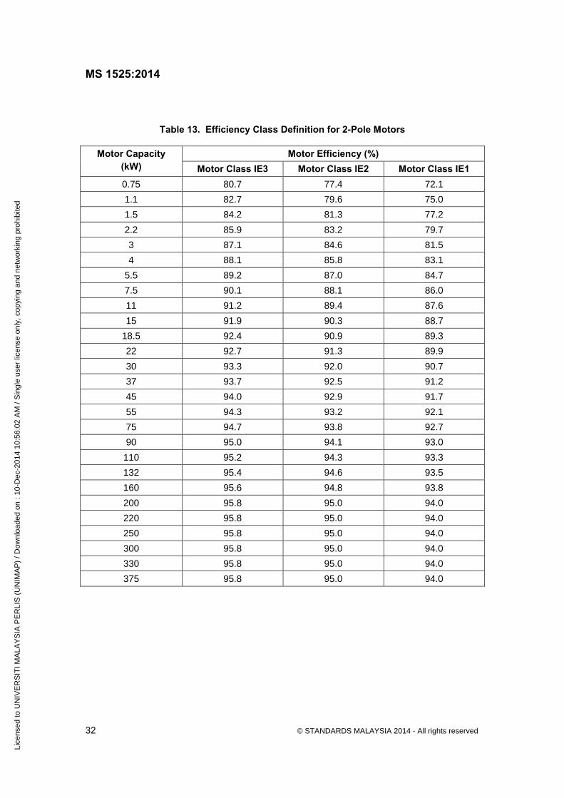
MS 1525:2014
32 © STANDARDS MALAYSIA 2014 - All rights reserved
11D062R
2
Table 13. Efficiency Class Definition for 2-Pole Motors
Motor Capacity (kW)
Motor Efficiency (%) Motor Class IE3 Motor Class IE2 Motor Class IE1
0.75 80.7 77.4 72.1
1.1 82.7 79.6 75.0
1.5 84.2 81.3 77.2
2.2 85.9 83.2 79.7
3 87.1 84.6 81.5
4 88.1 85.8 83.1
5.5 89.2 87.0 84.7
7.5 90.1 88.1 86.0
11 91.2 89.4 87.6
15 91.9 90.3 88.7
18.5 92.4 90.9 89.3
22 92.7 91.3 89.9
30 93.3 92.0 90.7
37 93.7 92.5 91.2
45 94.0 92.9 91.7
55 94.3 93.2 92.1
75 94.7 93.8 92.7
90 95.0 94.1 93.0
110 95.2 94.3 93.3
132 95.4 94.6 93.5
160 95.6 94.8 93.8
200 95.8 95.0 94.0
220 95.8 95.0 94.0
250 95.8 95.0 94.0
300 95.8 95.0 94.0
330 95.8 95.0 94.0
375 95.8 95.0 94.0
Lice
nsed
to U
NIV
ER
SIT
I MA
LAY
SIA
PE
RLI
S (
UN
IMA
P)
/ Dow
nloa
ded
on :
10-D
ec-2
014
10:5
6:02
AM
/ S
ingl
e us
er li
cens
e on
ly, c
opyi
ng a
nd n
etw
orki
ng p
rohi
bite
d

MS 1525:2014
© STANDARDS MALAYSIA 2014 - All rights reserved 33
11D062R
2
Table 14. Efficiency Class Definition for 4-Pole Motors
Motor Capacity (kW)
Motor Efficiency (%) Motor Class IE3 Motor Class IE2 Motor Class IE1
0.75 82.5 79.6 72.1
1.1 84.1 81.4 75.0
1.5 85.3 82.8 77.2
2.2 86.7 84.3 79.7
3 87.7 85.5 81.5
4 88.6 86.6 83.1
5.5 89.6 87.7 84.7
7.5 90.4 88.7 86.0
11 91.4 89.8 87.6
15 92.1 90.6 88.7
18.5 92.6 91.2 89.3
22 93.0 91.6 89.9
30 93.6 92.3 90.7
37 93.9 92.7 91.2
45 94.2 93.1 91.7
55 94.6 93.5 92.1
75 95.0 94.0 92.7
90 95.2 94.2 93.0
110 95.4 94.5 93.3
132 95.6 94.7 93.5
160 95.8 94.9 93.8
200 96.0 95.1 94.0
220 96.0 95.1 94.0
250 96.0 95.1 94.0
300 96.0 95.1 94.0
330 96.0 95.1 94.0
375 96.0 95.1 94.0
Lice
nsed
to U
NIV
ER
SIT
I MA
LAY
SIA
PE
RLI
S (
UN
IMA
P)
/ Dow
nloa
ded
on :
10-D
ec-2
014
10:5
6:02
AM
/ S
ingl
e us
er li
cens
e on
ly, c
opyi
ng a
nd n
etw
orki
ng p
rohi
bite
d
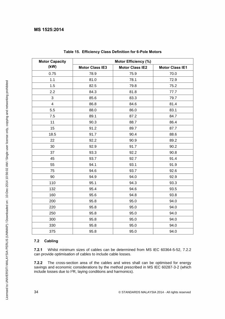
MS 1525:2014
34 © STANDARDS MALAYSIA 2014 - All rights reserved
11D062R
2
Table 15. Efficiency Class Definition for 6-Pole Motors
Motor Capacity (kW)
Motor Efficiency (%) Motor Class IE3 Motor Class IE2 Motor Class IE1
0.75 78.9 75.9 70.0
1.1 81.0 78.1 72.9
1.5 82.5 79.8 75.2
2.2 84.3 81.8 77.7
3 85.6 83.3 79.7
4 86.8 84.6 81.4
5.5 88.0 86.0 83.1
7.5 89.1 87.2 84.7
11 90.3 88.7 86.4
15 91.2 89.7 87.7
18.5 91.7 90.4 88.6
22 92.2 90.9 89.2
30 92.9 91.7 90.2
37 93.3 92.2 90.8
45 93.7 92.7 91.4
55 94.1 93.1 91.9
75 94.6 93.7 92.6
90 94.9 94.0 92.9
110 95.1 94.3 93.3
132 95.4 94.6 93.5
160 95.6 94.8 93.8
200 95.8 95.0 94.0
220 95.8 95.0 94.0
250 95.8 95.0 94.0
300 95.8 95.0 94.0
330 95.8 95.0 94.0
375 95.8 95.0 94.0
7.2 Cabling 7.2.1 Whilst minimum sizes of cables can be determined from MS IEC 60364-5-52, 7.2.2 can provide optimisation of cables to include cable losses. 7.2.2 The cross-section area of the cables and wires shall can be optimised for energy savings and economic considerations by the method prescribed in MS IEC 60287-3-2 (which include losses due to I2R, laying conditions and harmonics).
Lice
nsed
to U
NIV
ER
SIT
I MA
LAY
SIA
PE
RLI
S (
UN
IMA
P)
/ Dow
nloa
ded
on :
10-D
ec-2
014
10:5
6:02
AM
/ S
ingl
e us
er li
cens
e on
ly, c
opyi
ng a
nd n
etw
orki
ng p
rohi
bite
d
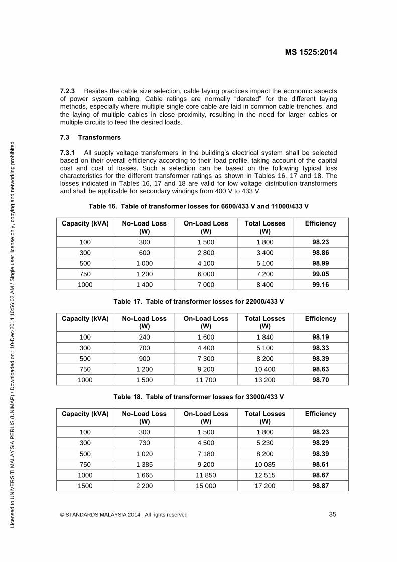
MS 1525:2014
© STANDARDS MALAYSIA 2014 - All rights reserved 35
11D062R
2
7.2.3 Besides the cable size selection, cable laying practices impact the economic aspects of power system cabling. Cable ratings are normally “derated” for the different laying methods, especially where multiple single core cable are laid in common cable trenches, and the laying of multiple cables in close proximity, resulting in the need for larger cables or multiple circuits to feed the desired loads. 7.3 Transformers 7.3.1 All supply voltage transformers in the building’s electrical system shall be selected based on their overall efficiency according to their load profile, taking account of the capital cost and cost of losses. Such a selection can be based on the following typical loss characteristics for the different transformer ratings as shown in Tables 16, 17 and 18. The losses indicated in Tables 16, 17 and 18 are valid for low voltage distribution transformers and shall be applicable for secondary windings from 400 V to 433 V.
Table 16. Table of transformer losses for 6600/433 V and 11000/433 V
Capacity (kVA) No-Load Loss (W)
On-Load Loss (W)
Total Losses (W)
Efficiency
100 300 1 500 1 800 98.23
300 600 2 800 3 400 98.86
500 1 000 4 100 5 100 98.99
750 1 200 6 000 7 200 99.05
1000 1 400 7 000 8 400 99.16
Table 17. Table of transformer losses for 22000/433 V
Capacity (kVA) No-Load Loss (W)
On-Load Loss (W)
Total Losses (W)
Efficiency
100 240 1 600 1 840 98.19
300 700 4 400 5 100 98.33
500 900 7 300 8 200 98.39
750 1 200 9 200 10 400 98.63
1000 1 500 11 700 13 200 98.70
Table 18. Table of transformer losses for 33000/433 V
Capacity (kVA) No-Load Loss (W)
On-Load Loss (W)
Total Losses (W)
Efficiency
100 300 1 500 1 800 98.23
300 730 4 500 5 230 98.29
500 1 020 7 180 8 200 98.39
750 1 385 9 200 10 085 98.61
1000 1 665 11 850 12 515 98.67
1500 2 200 15 000 17 200 98.87
Lice
nsed
to U
NIV
ER
SIT
I MA
LAY
SIA
PE
RLI
S (
UN
IMA
P)
/ Dow
nloa
ded
on :
10-D
ec-2
014
10:5
6:02
AM
/ S
ingl
e us
er li
cens
e on
ly, c
opyi
ng a
nd n
etw
orki
ng p
rohi
bite
d

MS 1525:2014
36 © STANDARDS MALAYSIA 2014 - All rights reserved
11D062R
2
7.3.2 Assessment of transformer efficiency in terms of load and no load losses may be effected using the following:
Transformer loss percentage = KVAP.F
NLLLL
100)(
Where LL is load losses in kW (winding losses); NLL is no load losses in kW (iron losses); P.F is power factor of load; and KVA is rated transformer capacity in KVA. Loss calculations would be: Iron (no load) loss + copper (load) loss. Iron losses = NLL x 8760 kWh/year, where NLL is the iron (no load loss) loss in kW Copper, or load losses = LLF x LL x 8760 kWh/year, where LLF is the loss load factor (nominally 0.3 x LF + 0.7 x LF^2) and the LL is the copper loss in kW at full load. The total loss should be summed over the transformer life and calculated on a “net present worth” basis over that period at a reasonable discount factor, and at estimated escalating economic tariffs over the same period. Other methods for selection of transformer that can be adopted include assessment of “Total Present Worth” of “Capital cost plus the capitalisation of the energy losses over the transformer lifetime”. 7.3.3 Transformer configuration should maintain a firm capacity that meets the full load requirements and shall not exceed 150 % of the load demand. 7.3.4 Distribution transformers should be located as close as possible to their load centres. As a general guide Table 19 can be used for this purpose.
Table 19. Location of distribution transformers
Load fed by transformer Distance of transformer from load centres
> 600 A Not more than 20 meters
300 A to 600 A Not more than 100 meters
7.3.5 Where harmonics content is significant, a transformer with higher harmonics withstand capability should be selected. 7.4 Inverters Inverters or variable speed drives (VSDs) should be used for motors serving fluctuating loads. VSDs can reduce energy consumption by adjusting motor speeds to cater for variable torque loads like fans and pumps, which traditionally vary their output by energy consuming mechanical means.
Lice
nsed
to U
NIV
ER
SIT
I MA
LAY
SIA
PE
RLI
S (
UN
IMA
P)
/ Dow
nloa
ded
on :
10-D
ec-2
014
10:5
6:02
AM
/ S
ingl
e us
er li
cens
e on
ly, c
opyi
ng a
nd n
etw
orki
ng p
rohi
bite
d
MS 1525:2014
© STANDARDS MALAYSIA 2014 - All rights reserved 37
11D062R
2
These inverters can also serve as motor starting mechanisms/devices to minimise voltage fluctuation disturbances to adjacent consumers due to high starting current. Starting mechanisms used shall suit the load capacity, starting frequency and the overall “system stiffness” at the location. In general “soft-start” mechanisms should be the preferred options. Except for consumer networks fed from their own MV (medium voltage) supply transformer substations, DOL (direct on line) starting shall be limited to motors not exceeding 5.0 kW (or 7.5 hp) capacity. For critical applications, such as hospitals and some manufacturing processes, the inverters need to be able to withstand or ‘ride through’ short duration voltage dips. The electronics in the VSDs, however, may result in increased harmonics and voltage spikes which may cause problems such as premature failures of motor insulation systems, increased motor losses, increased dielectric stress, overheating, resonance problems between the inductive and capacitive parts of the power network, malfunctioning of control systems, overloading and premature aging of capacitors, interference with telecommunications and computers, disturbances in ripple control systems, high currents in neutral conductors, etc. To overcome this, suitable harmonics filters will have to be used. 7.5 Power factor Power factor for motors shall be corrected to better than 0.85 when operating at duty point, to minimise losses due to reactive currents in the cables back to the main switchboard. The average power factor of the loads being served by the transformer should not be less than 0.85 or the utility tariff’s penalty baseline. In cases where load power factors fall below the baseline penalty value, power factor correction to a value exceeding the penalty baseline should be provided for, whether through automatic or manual correction. Power factor correction capacitors should be the low loss type with losses per kVAR not exceeding 0.35 W at upper temperature limit excluding the losses in the discharge resistors. 7.6 Sub metering To facilitate monitoring of energy consumption and energy management, electrical energy meters should be installed at strategic load centres to identify consumption by functional use (air conditioning, lighting etc.) and refer also to 9.8.
8 Air-conditioning and mechanical ventilation (ACMV) system 8.1 Load calculations 8.1.1 Calculation procedures Cooling system design loads for the purpose of sizing systems and equipment should be determined in accordance with the procedures described in the latest edition of the ASHRAE Handbook, or other equivalent publications. 8.1.2 Indoor design conditions Room comfort condition is dependent on various factors including air temperature, mean radiant temperature, humidity, clothing insulation, metabolic rate and air movement preference of the occupant.
Lice
nsed
to U
NIV
ER
SIT
I MA
LAY
SIA
PE
RLI
S (
UN
IMA
P)
/ Dow
nloa
ded
on :
10-D
ec-2
014
10:5
6:02
AM
/ S
ingl
e us
er li
cens
e on
ly, c
opyi
ng a
nd n
etw
orki
ng p
rohi
bite
d

MS 1525:2014
38 © STANDARDS MALAYSIA 2014 - All rights reserved
11D062R
2
For the purpose of engineering design, room comfort condition should consider the following three main factors: a) dry bulb temperature; b) relative humidity; and c) air movement (air velocity). In general, an individual feels comfortable when metabolic heat is dissipated at the rate at
which it is produced. The human body temperature needs to be maintained at a constant 37
0.5 C regardless of the prevailing ambient condition. The higher the space relative humidity, the lower the amount of heat the human body will be able to transfer by means of perspiration/evaporation. If the indoor air temperature is high and the relative humidity is high (above around 11.5 g vapour per kg dry air), the human body will feel uncomfortable. Generally, the relative humidity for indoor comfort condition should not exceed 70 %. Air movement (or air velocity) is essential for bodily comfort as it enhances heat transfer between air and the human body and accelerates cooling of the human body. Air movement in an occupied space gives a feeling of freshness by lowering the skin temperature, and the more varied the air currents in velocity and direction, the better the effect. A draught is created when the temperature of the moving air is too low and/or the velocity is too high. At
normal comfort room temperature (24 C to 26 C), the acceptable air velocity would be in the region of 0.15 m/s to 0.50 m/s. The indoor design conditions of an air-conditioned space for comfort cooling should be as follows:
a) recommended design dry bulb temperature 24 º C - 26 C
b) minimum dry bulb temperature 23 C c) recommended design relative humidity 50 % - 70 % d) recommended air movement 0.15 m/s - 0.50 m/s e) maximum air movement 0.70 m/s 8.1.3 Outdoor design parameters The recommended outdoor design parameters shall be as follows:
a) dry bulb temperature 33.3 C
b) wet bulb temperature 27.2 C 8.1.4 Ventilation Outdoor air-ventilation rates should comply with Third Schedule (By Law 41) Article 12(1) of Uniform Building by Laws, 1984.
Lice
nsed
to U
NIV
ER
SIT
I MA
LAY
SIA
PE
RLI
S (
UN
IMA
P)
/ Dow
nloa
ded
on :
10-D
ec-2
014
10:5
6:02
AM
/ S
ingl
e us
er li
cens
e on
ly, c
opyi
ng a
nd n
etw
orki
ng p
rohi
bite
d

MS 1525:2014
© STANDARDS MALAYSIA 2014 - All rights reserved 39
11D062R
2
Exception: Outdoor air quantities may exceed those shown, if required due to special occupancy or process requirements or source control of air contamination or indoor air quality consideration. 8.2 System and equipment sizing 8.2.1 Air conditioning systems and equipment shall be sized to provide no more than the space and system loads calculated in accordance with 8.1 above, consistent with available equipment capacity. Redundancy in capacity of equipment, if incorporated into the sizing of the duty equipment, should include efficiency devices such as variable speed drive, high efficiency motor, efficient unloading devices, multi compressors etc. so as not to diminish the equipment/system efficiency when operating at varying loads. 8.2.2 Where chillers are used and when the design load is greater than 1 000 kWr, a minimum of two chillers or a single multi-compressor chiller should be provided to meet the required load. 8.2.3 Multiple units of the same equipment type, such as multiple chillers, with combined capacities exceeding the design load may be specified to operate concurrently only if controls are provided which sequence or otherwise optimally control the operation of each unit based on the required cooling load. 8.2.4 Individual air cooled or water cooled direct expansion (DX) units greater than 35 kWr (reciprocating compressor) or 65 kWr (scroll compressor) should consist of either multi compressors or single compressor with step/variable unloaders. 8.2.5 Pump system efficiency For chilled water or condenser water pumping system operating for more than 750 hours a year, the pump efficiency shall be: a) > 70 % for flowrate between 50 m3/h to 100 m3/h;
b) > 73 % for flowrate between 100 m3/h to 270 m3/h; and
c) > 80 % for flowrate exceeding 270 m3/h. 8.3 Separate air distribution systems 8.3.1 Zones which are expected to operate non-simultaneously for more than 750 hours per year should be served by separate air distribution systems. As an alternative off-hour controls should be provided in accordance with 8.4.4. 8.3.2 Zones with special process temperature and/or humidity requirements should be served by separate air distribution system/s from those serving zones requiring only comfort cooling, or should include supplementary provisions so that the primary system/s may be specifically controlled for comfort purposes only.
Lice
nsed
to U
NIV
ER
SIT
I MA
LAY
SIA
PE
RLI
S (
UN
IMA
P)
/ Dow
nloa
ded
on :
10-D
ec-2
014
10:5
6:02
AM
/ S
ingl
e us
er li
cens
e on
ly, c
opyi
ng a
nd n
etw
orki
ng p
rohi
bite
d
MS 1525:2014
40 © STANDARDS MALAYSIA 2014 - All rights reserved
11D062R
2
Exception: Zones requiring comfort cooling only which are served by a system primarily used for process temperature and humidity control, need not be served by a separate system if the total supply air to these zones is no more than 25 % of the total system supply air, or the total conditioned floor area of the zones is less than 100 m2. 8.3.3 Separate air distribution systems should be considered for areas of the building having substantially different cooling characteristics, such as perimeter zones (3 m room depth) in contrast to interior zones. 8.3.4 For air conditioned space requiring exhaust air volume in excess of 3400 m3/h, not less than 85 % of non-conditioned make up air should be introduced directly into the space concerned unless the exhausted conditioned air is utilised for secondary cooling purposes. Alternatively, heat recovery devices should be provided. 8.4 Controls 8.4.1 Temperature control Each system should be provided with at least one thermostat for the regulation of temperature. Each thermostat should be capable of being set by adjustment or selection of
sensors over a minimum range of between 23 C to 27 C. Multi-stage thermostat should be provided for equipment exceeding 35/65 kWr in conjunction with 8.2.4. 8.4.1.1 Zoning for temperature control At least one thermostat for regulation of space temperature should be provided for: a) each separate system; and b) each separate zone as defined in 8.3. As a minimum each floor of a building should be considered as a separate zone. On a multi-storey building where the perimeter system offsets only the transmission gains of the exterior wall, an entire side of uniform exposure may be zoned separately. A readily accessible manual or automatic means should be provided to partially restrict or shut off the cooling input (for the exposure) to each floor. 8.4.1.2 Control setback and shut-off Each system should be equipped with a readily accessible means of shutting off or reducing the energy used during periods of non-use or alternate uses of the building spaces or zones served by the system. The following are examples that meet these requirements: a) manually adjustable automatic timing devices; b) manual devices for use by operating personnel; and c) automatic control system.
Lice
nsed
to U
NIV
ER
SIT
I MA
LAY
SIA
PE
RLI
S (
UN
IMA
P)
/ Dow
nloa
ded
on :
10-D
ec-2
014
10:5
6:02
AM
/ S
ingl
e us
er li
cens
e on
ly, c
opyi
ng a
nd n
etw
orki
ng p
rohi
bite
d

MS 1525:2014
© STANDARDS MALAYSIA 2014 - All rights reserved 41
11D062R
2
8.4.1.3 Multi zone systems These systems, other than those employing variable air volumes for temperature control should be provided with controls that will automatically reset the off-coil air supply to the highest temperature that will satisfy the zone requiring the coolest air. 8.4.2 Humidity control In a system requiring moisture removal to maintain specific selected relative humidity in spaces or zones, no new source of energy (such as electric reheat) should be used to produce a space relative humidity below 70 % for comfort cooling purposes. 8.4.2.1 Reheat systems Systems employing reheat where permitted by 8.4.2 and serving multiple zones, other than those employing variable air volume for temperature control, should be provided with controls that will automatically reset the system cold air supply to the highest temperature level that will satisfy the zone requiring the coolest air. Single zone reheat systems should be controlled to sequence reheat and cooling. 8.4.3 Energy recovery It is recommended that consideration be given to the use of recovery systems which will conserve energy (provided the amount expended is less than the amount recovered) when the energy transfer potential and the operating hours are considered.
Recovered energy in excess of the new source of energy expended in the recovery process may be used for control of temperature and humidity. Examples include the use of condenser water for reheat, super heater heat reclaim, heat recovery wheel, heat pipe or any other energy recovery technology. 8.4.4 Off-hour control 8.4.4.1 ACMV system should be equipped with automatic controls capable of accomplishing a reduction of energy use for example through equipment shutdown during periods of non-use or alternative use of the spaces served by the system. Exceptions: a) systems serving areas which are expected to operate continuously; and b) equipment with a connected load of 2 kW or less may be controlled by readily accessible
manual off-hour controls. 8.4.4.2 Outdoor air supply and exhaust systems should be provided with motorised or gravity dampers or other means of automatic volume shut-off or reduction during period of non-use or alternate use of the spaces served by the system. Exceptions: a) systems serving areas which are expected to operate continuously; b) systems which have a design air flowrate of 1 800 m3/h or less;
Lice
nsed
to U
NIV
ER
SIT
I MA
LAY
SIA
PE
RLI
S (
UN
IMA
P)
/ Dow
nloa
ded
on :
10-D
ec-2
014
10:5
6:02
AM
/ S
ingl
e us
er li
cens
e on
ly, c
opyi
ng a
nd n
etw
orki
ng p
rohi
bite
d

MS 1525:2014
42 © STANDARDS MALAYSIA 2014 - All rights reserved
11D062R
2
c) gravity and other non-electrical ventilation systems which may be controlled by readily
accessible manual damper controls; and d) where restricted by process requirements such as combustion air intakes. 8.4.4.3 Systems that serve zones which can be expected to operate non-simultaneously for more than 750 hours per year should include isolation devices and controls to shut off the supply of cooling to each zone independently. Isolation is not required for zones expected to operate continuously. 8.4.4.4 For buildings where occupancy patterns are not known at time of system design, isolation areas should be pre-designed. 8.4.4.5 Zones may be grouped into a single isolation area provided the total conditioned floor area does not exceed 250 m2 per group nor include more than one floor unless variable air volume or equivalent devices are incorporated. Use of outside economy air cycle design where feasible should be considered.
8.4.5 Mechanical ventilation control Each mechanical ventilation system (supply and/or exhaust) should be equipped with a readily accessible switch or other means for shut-off or volume reduction when ventilation is not required. Examples of such devices would include timer switch control, thermostat control, duty cycle programming and CO/CO2 sensor control. 8.4.6 Fan system efficiency For fan system with air flow rate exceeding 17 000 m3/h and operating for more than 750 hours a year, the power required by the motor for the entire fan system at design conditions should not exceed 0.42 W per m3/h of air flow rate. 8.5 Piping insulation All piping installed to serve buildings and within buildings should be adequately insulated to prevent excessive energy losses. Additional insulation with vapour barriers may be required to prevent condensation under some conditions. Exceptions: Piping insulation is not required in any of the following cases: a) piping installed within ACMV equipment;
b) piping at fluid temperatures between 23 C and 49 C; and c) when the heat loss and/or heat gain of the piping, without insulation, does not increase
the energy requirements of the building. 8.6 Air handling duct system insulation All ducts, plenums and enclosures installed in or on buildings should be adequately insulated to prevent excessive energy losses. Additional insulation with vapour barriers may be required to prevent condensation under some conditions.
Lice
nsed
to U
NIV
ER
SIT
I MA
LAY
SIA
PE
RLI
S (
UN
IMA
P)
/ Dow
nloa
ded
on :
10-D
ec-2
014
10:5
6:02
AM
/ S
ingl
e us
er li
cens
e on
ly, c
opyi
ng a
nd n
etw
orki
ng p
rohi
bite
d
MS 1525:2014
© STANDARDS MALAYSIA 2014 - All rights reserved 43
11D062R
2
Exceptions: Duct insulation is not required in the following cases: a) where the design temperature differential between the air in the duct and the surrounding
air is 8 C or less provided that the duct is within the air-conditioned space; b) when the heat gain or loss of the ducts, without insulation, will not increase the energy
requirements of the building; c) within ACMV equipment; and d) exhaust air ducts subject to qualification as in 8.6 a). 8.7 Duct construction All ductwork should be constructed and erected in accordance with ANSI/SMACNAHVAC Duct Construction Standards - Metal and Flexible published by Sheet Metal and Air Conditioning Contractors’ National Association (SMACNA) or any other equivalent duct construction standards. 8.7.1 High-pressure and medium-pressure ducts should be leak tested in accordance with HVAC Air Duct Leakage Test Manual published by SMACNA or any other equivalent standards, with the rate of leakage not to exceed the maximum rate specified. 8.7.2 When low pressure supply air ducts are located outside of the conditioned space (except return air plenums), all transverse joints should be sealed using mastic or mastic plus tape or equivalent material. For fibrous glass ductwork, pressure sensitive tape is acceptable. 8.7.3 Automatic or manual dampers installed for the purpose of shutting off outside air intake for ventilation air should be designed with tight shut-off characteristics to minimise air leakage. 8.8 Balancing The system design should provide means for balancing the air and water system such as but not limited to dampers, temperature and pressure test connections and balancing valves. 8.9 ACMV systems For the purposes of this part, ‘ACMV Systems’ are considered to be of two basic types: a) central system This type of system in turn comprises:
i) water* distribution Under this component, a centrifugal, rotary, screw, scroll or reciprocating, compression refrigeration or absorption refrigeration type water-chilling package generates chilled water to a central piping system which supplies the chilled water, as required, to the conditioned space(s) of a building. *includes other fluids e.g. glycol or brine solutions
Lice
nsed
to U
NIV
ER
SIT
I MA
LAY
SIA
PE
RLI
S (
UN
IMA
P)
/ Dow
nloa
ded
on :
10-D
ec-2
014
10:5
6:02
AM
/ S
ingl
e us
er li
cens
e on
ly, c
opyi
ng a
nd n
etw
orki
ng p
rohi
bite
d

MS 1525:2014
44 © STANDARDS MALAYSIA 2014 - All rights reserved
11D062R
2
ii) air distribution This component consists of terminal units which receive recirculated room air (plus outside air as required) from a central duct system, performs the required ventilating and/or air-conditioning functions, and delivers the conditioned air to the central duct system, for final delivery to the conditioned space(s) of a building. These terminal units receive chilled water from the central piping system to perform the cooling and dehumidification functions. The water chilling package, including its heat-rejecting element, pumps and the terminal units are termed as ACMV System Components under 8.11. b) unitary system In this system, one or more assembled units, which include an evaporator or cooling coil, compressor and condenser, perform the cooling and dehumidification functions on the re-circulated air from the conditioned space (plus outside air as required). The distribution of air from the unitary system into the conditioned space can either be of non-ducted or ducted type. These systems are termed as ACMV System Equipment under 8.10. 8.10 ACMV system equipment ACMV system equipment provides, in one (single package) or more (split system) factory assembled packages, means for air-circulation, air-cleaning, air-cooling with controlled temperature and dehumidification. The cooling function may be either electrically or heat operated, and the refrigerant condenser may be air, water or evaporatively-cooled. Where the equipment is provided in more than one package, the separate packages should be designed by the manufacturer to be used together. 8.10.1 ACMV system equipment, electrically operated, cooling mode 8.10.1.1 ACMV system equipment as per in 8.10.1.2 whose energy input in the cooling mode is entirely electric, should show a coefficient of performance (COP) cooling as defined in 3.2 at the standard rating conditions specified in Table 20 and additional standard rating conditions specified in applicable standards for particular ACMV system equipment not less than values shown in Table 21. 8.10.1.2 These requirements apply to but are not limited to central and unitary cooling equipment (air-cooled, water-cooled and evaporatively-cooled) and packaged terminal air-conditioners.
Lice
nsed
to U
NIV
ER
SIT
I MA
LAY
SIA
PE
RLI
S (
UN
IMA
P)
/ Dow
nloa
ded
on :
10-D
ec-2
014
10:5
6:02
AM
/ S
ingl
e us
er li
cens
e on
ly, c
opyi
ng a
nd n
etw
orki
ng p
rohi
bite
d

MS 1525:2014
© STANDARDS MALAYSIA 2014 - All rights reserved 45
11D062R
2
Table 20. ACMV system equipment, electrically driven1: Standard rating temperatures - cooling2
Item Air-cooled
Water-cooled (water-source)
Dry-bulb Wet-bulb Inlet Outlet
Room air entering equipment (°C)
Condenser ambient (air-cooled) (°C)
Refrigerant-water heat exchanger (°C)
27.0
35.0
-
19.0
24.0
-
-
-
30.0
-
-
35.0
NOTES:
1. Data in this table apply to the following types of equipment: a) central Air Conditioners: Air, Evaporatively and Water Cooled, ISO 13253; and b) commercial/Industrial Unitary Air- Conditioning Equipment, MS ISO 5151, ISO 13253. 2. Standard ratings are also based on other standard rating conditions such as, but not limited to,
electrical conditions; cooling coil air quantity; requirements for separated (split) assemblies; and minimum external flow resistance, as provided in the applicable standards.
Table 21. Unitary air conditioners, electrically driven:
Minimum COP - cooling
Equipment Size Sub-category Minimum COP
Non-Inverter type Inverter type 1
Air conditioners:
Air cooled with condenser
<19 kWr Single Split/Package
2.8 3.0
Multi-split 2.8 3.2
19 kWr and
< 35 kWr
Split or Package
2.8 3.5
35 kWr
Split or Package
2.7 2.9
Air conditioners:
Water and evaporatively cooled
< 19 kWr
Split or Package
3.6 4.0
19 kWr and
< 35 kWr
Split or
Package
3.7
4.4
35 kWr
Split or Package
3.8 4.4
NOTE:
1. The COP for the inverter unit is the weighted value, which is calculated based upon the following equation:
0.600.40 % 50% 100 COPCOPCOPweighted
Lice
nsed
to U
NIV
ER
SIT
I MA
LAY
SIA
PE
RLI
S (
UN
IMA
P)
/ Dow
nloa
ded
on :
10-D
ec-2
014
10:5
6:02
AM
/ S
ingl
e us
er li
cens
e on
ly, c
opyi
ng a
nd n
etw
orki
ng p
rohi
bite
d

MS 1525:2014
46 © STANDARDS MALAYSIA 2014 - All rights reserved
11D062R
2
8.10.1.3 In calculating the COP of ducted systems, the effective power input (Peff) of the indoor re-circulating fan is used, which is given as:
3.0
svinputeff
pqPP
where Pinput the input power of the fan motor (W); qv is rated air flow rate (m3/hr); and Δps the external static pressure difference (Pa). 8.11 ACMV system components
ACMV system components provide, in one or more factory-assembled packages, means for chilling water with controlled temperature, for delivery to terminal units serving the conditioned space of the building. The chiller may be of the centrifugal, rotary, screw, scroll or reciprocating, electrically driven type, absorption (heat-operated) type or using other prime movers. A second type of ACMV System Components involves the condensing unit, which receives its suction refrigerant vapour from a packaged or field assembled combination of cooling coil and fan (central station air handling unit) and delivers liquid refrigerant to the air handling unit. 8.11.1 ACMV system components, electrically operated, cooling mode ACMV system components, as listed in Table 23, whose energy input is entirely electrical, should, at the Standard Rating Conditions specified in Table 22 for water chillers and at additional standard rating conditions specified in applicable standards for particular system components show a Coefficient of Performance (COP) - cooling, as defined in 3.2 not less than the values shown in Table 23.
Table 22. ACMV system components, electrically driven1 for water chillers: Standard rating conditions - cooling2
Conditions Water Chilling Package
Leaving chilled water temperature oC (oF)
Entering chilled water temperature oC (oF)
6.67 (44)
12.22 (54)
Leaving condenser water temperature oC (oF)
Entering condenser water temperature oC (oF)
36.11 (97)
30.55 (87)
Fouling factor, waterc
Condenser m2 K/kW
Evaporator m2 K/kW
0.044
0.018
Condenser, ambient Temperature
Air-cooled oC
Evaporatively-cooled oC
35.0 DB
24.0 WB
NOTES:
1. Data in this table apply to the following types of ACMV System Components: Centrifugal or Rotary or Reciprocating water-chilling packages complying to MS 2449.
2. Air-cooled unit ratings is rated at sea level at Barometric Pressure of 101.3 kPa.
Lice
nsed
to U
NIV
ER
SIT
I MA
LAY
SIA
PE
RLI
S (
UN
IMA
P)
/ Dow
nloa
ded
on :
10-D
ec-2
014
10:5
6:02
AM
/ S
ingl
e us
er li
cens
e on
ly, c
opyi
ng a
nd n
etw
orki
ng p
rohi
bite
d

MS 1525:2014
© STANDARDS MALAYSIA 2014 - All rights reserved 47
11D062R
2
The energy consumed by the external water pumps circulating chilled water, and the heat rejecting device (cooling tower or heat exchanger) are not included in the COP consideration for the ACMV system component, unless the device (i.e. air-cooled condenser) is integrally incorporated into the package by the manufacturer.
Table 23. Water chilling packages, electrically driven: Chiller energy performance rating
Equipment Size
1COP at 100 % Load At M’sian test
Conditions
aMPLV at MS Std Conditions
2COP at 100 % Load at Std AHRI test
Conditions
bIPLV at AHRI Std Conditions
Minimum COP
Maximum kWe/RT
Minimum COP
Maximum kWe/RT
Minimum COP
Maximum kWe/RT
Minimum COP
Maximum kWe/RT
Air cooled,
with condenser
< 105 kWr
(30 RT) 2.79 1.26 3.20 1.10 2.79 1.26 3.66 0.96
≥ 105 kWr and < 530 kWr
(150 RT)
2.79 1.26 3.20 1.10 2.79 1.26 3.66 0.96
≥ 530 kWr and < 1060 kWr
(300 RT)
2.79 1.26 3.35 1.05 2.79 1.26 3.74 0.94
≥ 1060 kWr
(300 RT) 2.79 1.26 3.35 1.05 2.79 1.26 3.74 0.94
Water cooled, positive
Displacement
(Reciprocating, scroll, Rotary screw)
(< 260 kWr)
(< 75 RT) 4.34 0.81 4.14 0.85 4.51 0.78 5.58 0.63
> 260 < 530 kWr
(150 RT)
4.34 0.81 4.14 0.85 4.51 0.78 5.67 0.62
≥ 530 kWr and < 1060 kWr
(300 RT)
4.95 0.71 4.45 0.79 5.17 0.68 6.06 0.58
≥ 1060 kWr
(300 RT) 5.41 0.65 4.82 0.73 5.67 0.62 6.51 0.54
Water cooled,
Centrifugal
< 1060 kWr
(300 RT) 5.33 0.66 5.02 0.70 5.58 0.63 5.86 0.60
≥ 1060 kWr
(300 to 600 RT) 5.86 0.60 5.41 0.65 6.06 0.58 6.39 0.55
> 600 RT 5.96 0.59 5.58 0.63 6.17 0.57 6.51 0.54
Lice
nsed
to U
NIV
ER
SIT
I MA
LAY
SIA
PE
RLI
S (
UN
IMA
P)
/ Dow
nloa
ded
on :
10-D
ec-2
014
10:5
6:02
AM
/ S
ingl
e us
er li
cens
e on
ly, c
opyi
ng a
nd n
etw
orki
ng p
rohi
bite
d

MS 1525:2014
48 © STANDARDS MALAYSIA 2014 - All rights reserved
11D062R
2
NOTES : 1 Tested at Malaysian Chilled Water and Condenser Water Temperatures as per Table 23. Chillers without condensers can be rated with matching condensers and comply with the chiller efficiency requirements. 2 Tested at AHRI Leaving Chilled Water Temperature of 44 °F at 2.4 USGPM per tonne, and entering Condenser Water Temperature of 85 °F at 3 USGPM per tonne. a MPLV denotes Malaysia Part Load Value which is a single part load efficiency figure of merit calculated per method described in MS 2449 at Malaysia Standard Rating Conditions, where for part-load entering condenser water temperatures (ECWT), the temperature should vary linearly from the selected ECWT at 100 % load to 26.67 °C (80 °F) at 50 % load and fixed at 26.67 °C (80 °F) for 50 % to 0 % load, and is defined by the following formula:
(For part-load entering air dry bulb temperatures, the temperature should be vary linearly from selected
EDB at 100 % load to 25.55 °C (78 °F) at 33 % load and fixed at 25.55 °C (78 °F) for 33 % to 0 %
loads).
Where
A = kWe/RT at 100 %
B = kWe/RT at 75 %
C = kWe/RT at 50 %
D = kWe/RT at 25 %
b IPLV denotes Integrated Part Load Value which is a single number part-load efficiency figure of merit calculated per method described in AHRI 550/90 where for part-load entering condenser water temperatures (ECWT), the temperature should vary linearly from the selected ECWT at 100 % load to 18.33 °C (65 °F) at 50 % loads, and fixed at 18.33 °C (65 °F) for 50 % to 0 % loads and is defined by the following formula:
Chiller efficiency rating compliance shall meet either Minimum COP at 100 % Load Condition or Minimum MPLV and not at both conditions. Note that COP is applicable to a single chiller.
8.12 ACMV system equipment/component - heat-operated (absorption), cooling mode 8.12.1 Coefficient of performance (COP) - Cooling The definition in 3.2 applies together with the following supplementary. In the heat-operated (absorption) system equipment/components, pumps included in the package for circulating refrigerant and absorber fluids in the refrigeration cycle are included in determining the COP of the equipment/components. Heat-operated cooling equipment/components shall show a COP-cooling not less than the values shown in Table 25 when tested at standard rating conditions shown in Table 24. For heat-operated cooling equipment /component, the heat energy input should be limited to: a) solar energy; b) recovered energy from other processes; and c) natural gas or others (non electric).
Lice
nsed
to U
NIV
ER
SIT
I MA
LAY
SIA
PE
RLI
S (
UN
IMA
P)
/ Dow
nloa
ded
on :
10-D
ec-2
014
10:5
6:02
AM
/ S
ingl
e us
er li
cens
e on
ly, c
opyi
ng a
nd n
etw
orki
ng p
rohi
bite
d

MS 1525:2014
© STANDARDS MALAYSIA 2014 - All rights reserved 49
11D062R
2
Table 24. ACMV system cooling equipment/component, heat-operated: Standard rating conditions - cooling
Standard rating conditions
Heat source Direct fired (Gas, oil)
Indirect fired (Steam, hot water)
Airconditioners1 Units Temperatures Temperatures
Entering condenser air oC 35.0 DB, 24.0 WB -
Water chillers2
Leaving chilled water
Fouling factor
Entering chilled water
Entering condenser
Fouling factor
Leaving condenser water
oC (oF)
m2 K/kW
oC (oF)
oC (oF)
m2 K/kW
oC (oF)
6.67 (44)
0.018
12.22 (54)
30.55 (87)
0.044
36.11 (97)
6.67 (44)
0.018
12.22 (54)
30.55(87)
0.044
36.11 (97)
NOTES: 1. Per ANSI Standard Z21.40.1 and Addenda for Gas-fired absorption summer air-conditioning appliances. 2. Per AHRI Standard 560 for Absorption water-chilling packages.
Table 25. ACMV system cooling equipment/components, heat-operatedb:
Minimum COPc - cooling
Heat Source Direct fired (Gas, Oil)
Indirect fired (Steam, hot water)
Type Xa Type Ya Type Xa Type Ya
Not applicable 0.95 0.6 1.0
NOTES:
1. a Type X = Single effect absorption chillers a Type Y = Double effect absorption chillers
2. b As listed in Table 20 at sea level.
3. c Minimum COP = Net cooling output
Total heat input (electrical auxillary input included)
Lice
nsed
to U
NIV
ER
SIT
I MA
LAY
SIA
PE
RLI
S (
UN
IMA
P)
/ Dow
nloa
ded
on :
10-D
ec-2
014
10:5
6:02
AM
/ S
ingl
e us
er li
cens
e on
ly, c
opyi
ng a
nd n
etw
orki
ng p
rohi
bite
d
MS 1525:2014
50 © STANDARDS MALAYSIA 2014 - All rights reserved
11D062R
2
8.13 System testing and commissioning Air system balancing should be accomplished in a manner to minimise throttling losses and the fan speed should be adjusted to meet design flow conditions. Hydraulic system balancing should be accomplished in a manner to minimise throttling losses and the pump impeller should be trimmed or pump speed should be adjusted to meet design flow conditions. ACMV control systems should be tested to assure that control elements are calibrated, adjusted and in proper working condition. 8.14 Operation and maintenance manual and as-built drawings An operation and maintenance manual and as-built drawings should be provided to the owner. The manual should include basic data relating to the operation and maintenance of ACMV systems and equipment. Required routine maintenance action should be clearly identified. Where applicable, ACMV controls information such as diagrams, schematics, control sequence descriptions and maintenance and calibration information should be included. As-built drawings should contain information relating to rated capacities of all air conditioning plants which includes, but not limited to air handling units and fans. 8.15 Preventive maintenance The owner should implement preventive maintenance system and schedule periodic maintenance on all the critical items of air-conditioning systems such as compressors, cooling towers, pumps, condensers, air handlers, controls, filters and piping.
9 Energy management control system 9.1 Energy Management System (EMS) The Energy Management System (EMS) is a subset of the building automation system function. It should be considered for buildings with air-conditioned space > 4 000 m2. The EMS is a state-of-the-art system and is microprocessor based. Generally, the EMS has three main functions: a) control of equipment; b) monitoring of equipment; and c) integration of equipment sub-systems. 9.2 Control of equipment The primary purpose of the control of equipment is to save energy by (preferably real-time) optimisation system controls. This is performed by the EMS function of the building automation system through; a) scheduling and manual overriding;
Lice
nsed
to U
NIV
ER
SIT
I MA
LAY
SIA
PE
RLI
S (
UN
IMA
P)
/ Dow
nloa
ded
on :
10-D
ec-2
014
10:5
6:02
AM
/ S
ingl
e us
er li
cens
e on
ly, c
opyi
ng a
nd n
etw
orki
ng p
rohi
bite
d

MS 1525:2014
© STANDARDS MALAYSIA 2014 - All rights reserved 51
11D062R
2
b) control of set points; c) report and record operational alarms; and d) ensure correct and safe sequence of operation (for maximum demand limiting). 9.3 Monitoring of equipment The purpose of monitoring the equipment is to improve the efficiency of operations by: a) providing centralised information of current equipment conditions; b) providing information of equipment conditions through basic trending; c) providing a “management by exception” function to alert the operator of any abnormal
equipment conditions; and d) providing analytical tools to aid the study and management of equipment operations and
energy performance. 9.4 Integration of equipment subsystems Equipment subsystems are integrated for the purpose of improving: a) safety/security; for example, in the event of a fire, air-handling units can be used to create
a sandwich system for smoke control; b) indoor air quality; for example, by utilising the smoke purging system for periodic air
purging to achieve good indoor air quality; c) information management; by allowing information from multiple equipment subsystems to
be monitored, stored and reported in a consistent format; and d) overall system reliability; the intelligent controller of an equipment subsystem may be
configured to provide redundancy as a standby unit for another system/s without incurring additional cost.
9.5 Energy consuming areas 9.5.1 Air conditioning and mechanical ventilation (ACMV) system The system is typically the largest energy consumer in the building and has the largest energy savings potential. The EMS shall place special emphasis on the ACMV system as specified in 9.6. 9.5.2 Lighting system The lighting system is typically the second largest energy consumer in the building and is recommended for inclusion in the EMS as specified in 9.7. If included in EMS, the following should be considered; a) the capability and capacity of facilities management to maintain and operate EMS
controlled lighting system.
Lice
nsed
to U
NIV
ER
SIT
I MA
LAY
SIA
PE
RLI
S (
UN
IMA
P)
/ Dow
nloa
ded
on :
10-D
ec-2
014
10:5
6:02
AM
/ S
ingl
e us
er li
cens
e on
ly, c
opyi
ng a
nd n
etw
orki
ng p
rohi
bite
d

MS 1525:2014
52 © STANDARDS MALAYSIA 2014 - All rights reserved
11D062R
2
b) as lighting system in EMS is typically ‘a massively switched array’, its design and
implementation needs to account for maintainability and flexibility for scaling up and changes.
9.5.3 Others Any other large energy consuming equipment such as water pump sets, electric or gas heaters and others should be included under the EMS programme. It is recommended that monitoring of renewable energy sources such as solar and wind energy systems be included to assist users visualise energy balance and thence maximise the harvesting of such renewable energy sources. Also due the inter-relationship between water and energy, it is recommended for the EMS to monitor and capture data on water use efficiency as well as incorporate water leakage alarm. However, it is typically not appropriate to apply the EMS to control equipment such as computers. 9.6 Application of an EMS to the ACMV system 9.6.1 Central plant In buildings where chillers are used, the EMS should be used to issue start/stop commands to the chiller control panel. The start /stop commands should be based on as follows: a) time schedules to match occupancy patterns; and b) selection of the most energy efficient combination of chillers to satisfy building load; this is
known as chiller sequencing or chiller optimisation programming. Chillers are typically supplied with microprocessor based control panels. Where possible, a high level data interface between the chiller control panel and the EMS should be provided. The chiller is typically the largest single energy consumer in the building. The energy consumed by a chiller decreases as the set point of the leaving chilled water is increased. The EMS should automatically increase the set point of the leaving chilled water whenever possible to minimise energy consumption. The EMS may adjust the set point based on (but not limited to): a) time schedule; b) outdoor air temperature/enthalpy; c) maximum AHU valve position; and d) indoor relative humidity condition. 9.6.2 Air handling units (AHUs) The EMS should have the facility to start and stop the air handling units based on a time schedule. For further energy savings, the cooling coil valve of the AHUs should be controlled by an intelligent controller which integrates with the EMS.
Lice
nsed
to U
NIV
ER
SIT
I MA
LAY
SIA
PE
RLI
S (
UN
IMA
P)
/ Dow
nloa
ded
on :
10-D
ec-2
014
10:5
6:02
AM
/ S
ingl
e us
er li
cens
e on
ly, c
opyi
ng a
nd n
etw
orki
ng p
rohi
bite
d
MS 1525:2014
© STANDARDS MALAYSIA 2014 - All rights reserved 53
11D062R
2
Where permitted by the mechanical design of the AHU, the speed of the fan should be decreased and the set point of the cooling valve control loop should be increased to minimise energy consumption. For Variable Air Volume AHU system, the EMS should be capable of adjusting the set point based on (but not restricted to), static pressure reset inside the main supply air duct. Control of outdoor air supply to the AHU is recommended to be based on demand control ventilation to optimise energy consumption while maintaining healthy indoor air quality, for example by incorporating CO2 sensor. 9.6.3 Terminal units Terminal units which include variable air volume (VAV) boxes and fan coil units (FCUs) should be integrated with the EMS for start/stop control. Some applications may require a number of FCUs to be grouped together as a common zone for start/stop control by the EMS. 9.6.4 Unitary systems Unitary systems are designed to be self-contained or packaged units. Where unitary systems are provided with independent/dedicated control and monitoring of energy and performance, such provisions should have the capability of integration or high level interface for energy consumption and performance control (start/stop, temperature control, etc.) with the EMS. 9.6.5 Mechanical ventilation Where appropriate the EMS should start/stop mechanical ventilation equipment such as supply or exhaust fans. Some applications may require a number of fans to be grouped together as a common zone for start/stop control by the EMS. Control should be based on, but not limited to: a) time schedules; b) carbon monoxide (CO) or carbon dioxide (CO2) level in parking garages or large rooms
with highly variable occupancy; and c) duty cycling algorithm. 9.6.6 Pumps Chilled water and condenser water pumps larger than 2 kWe and operating for more than 750 hours per year should incorporate digital power meter/s linked to the EMS. 9.7 Application of EMS to the lighting system 9.7.1 Lighting systems shall be provided with manual, automatic or programmable controls except: a) those required for emergency lighting; b) those required for exit lighting; and c) continuous lighting required for security purposes.
Lice
nsed
to U
NIV
ER
SIT
I MA
LAY
SIA
PE
RLI
S (
UN
IMA
P)
/ Dow
nloa
ded
on :
10-D
ec-2
014
10:5
6:02
AM
/ S
ingl
e us
er li
cens
e on
ly, c
opyi
ng a
nd n
etw
orki
ng p
rohi
bite
d

MS 1525:2014
54 © STANDARDS MALAYSIA 2014 - All rights reserved
11D062R
2
The minimum number of controls should not be less than one for every 1 000 W of connected lighting power. For applications where automatic control is feasible, savings in lighting energy may be further realised through (but not limited to) incorporating devices such as “Lighting Sweep Logic” where lights turned off at night will remain off by means of the EMS periodically “sweeping” them off. 9.7.2 Common areas Lighting for common areas includes: a) decorative lighting; b) security lighting; c) lobby lighting; d) corridor lighting; and e) facade lighting. Where appropriate, lighting for common areas should be controlled by the EMS. Control of lighting for common areas should typically be based on time of day schedules or occupancy schedules or light level detection. 9.7.3 Work areas In cases where the EMS controls the lighting in the work areas, local override switches should be provided to allow localised control. The status of these switches should be monitored by the EMS. Control of lighting for work areas should typically be based on occupancy schedules. 9.8 Applications of EMS to energy audit Buildings provided with EMS as specified in 9.1 should be equipped with utility consumption (utility refers to electricity, fuel, gas, compressed air, etc.) data logging facilities for the collation of data for energy auditing. Suitable means or facilities for the monitoring of energy consumption (sub-metering) should be provided to all incoming power supply to a building and the outgoing sub-circuits serving, but not limited to the following: a) central air-conditioning system and/or external supplied cooling water; b) lift and escalator system; c) major water pumping system; d) general power supply; and e) lighting supply to tenancy areas and landlord areas.
Lice
nsed
to U
NIV
ER
SIT
I MA
LAY
SIA
PE
RLI
S (
UN
IMA
P)
/ Dow
nloa
ded
on :
10-D
ec-2
014
10:5
6:02
AM
/ S
ingl
e us
er li
cens
e on
ly, c
opyi
ng a
nd n
etw
orki
ng p
rohi
bite
d

MS 1525:2014
© STANDARDS MALAYSIA 2014 - All rights reserved 55
11D062R
2
9.9 Characteristics of EMS The EMS should be supplied with a full complement of energy management features including but not limited to: a) direct digital control algorithms; b) starting and stopping of equipment based on a time schedule and optimisation control logic; c) temporary override of the time schedules to accommodate changes in usage; d) chilled water leaving and/or entering temperature reset algorithm; e) control loop set point reset algorithm; f) chiller sequencing and optimisation algorithm; g) demand limiting algorithm; and h) duty cycling algorithm. The EMS should come with an energy tracking and reporting system so that a historical record of energy usage is maintained for analysis and energy audit purposes. EMS monitoring should consist of the following categories (but not limited to) of data collection; a) energy consumption; b) pattern identification/profiling; and c) operation alarm notification. The level of actual energy consumption is based on the collection of energy usage data by power meters while pattern identification requires the mapping of building activities that are known to have specific energy consumption characteristics. Where applicable, provision should also be made for automatic conversion of fuel energy use into its electrical energy equivalent. Accurate and meticulous information from pattern identification (more than what would appear on a total utility bill) will enable users to formulate feasible energy savings strategies. EMS Software that monitors energy should be able to do (preferably real time) reporting and capable of comparing recent data against historical data. Such monitoring can be useful for users who wish to track the energy consumption of very specific areas in a building, analyse days while taking weather into consideration and identify energy consumption that is unexpected or incongruous with previous data. All of these monitoring functions provide a user with opportunities to streamline energy usage. EMS software that allows comparison of meter readings with utility bills can help users keep track of both historical and present energy consumption and identify possible mistakes and anomalies. With some types of energy management software, users can set their own acceptable energy usage levels or implement energy savings plans. If these levels or plans are exceeded, the software can alert a user through email or text messages.
Lice
nsed
to U
NIV
ER
SIT
I MA
LAY
SIA
PE
RLI
S (
UN
IMA
P)
/ Dow
nloa
ded
on :
10-D
ec-2
014
10:5
6:02
AM
/ S
ingl
e us
er li
cens
e on
ly, c
opyi
ng a
nd n
etw
orki
ng p
rohi
bite
d
MS 1525:2014
56 © STANDARDS MALAYSIA 2014 - All rights reserved
11D062R
2
Ideally, the EMS should be capable of providing the following types of information (but not limited to) on trending: a) temperature; b) pressure; c) damper and valve position commands, including variable frequency drive control signals; d) virtual points (internal calculations such as enthalpy or changing set-points and targets); e) (ON/OFF) status or stage; f) flow rate (water, air or fuel); g) alarm state; h) current; i) power demand (kW); j) energy consumption (kWh, therms, gallons, etc.); and k) revolutions per minute (RPM). 9.10 Training for users
Users should be comprehensively trained on the features and benefits of the EMS. The maintenance or building operators should be trained for the following, but not limited to: a) setting of time schedule for equipment Start/Stop operation; b) manual centralised equipment Start/Stop controls from the EMS; c) manual by-pass of the EMS and resetting back to Auto Mode of the EMS; d) historical retrieval and trending for data analysis; and e) acknowledgement of alerts/alarms and troubleshooting of the EMS or equipment. 9.11 Testing and commissioning To ensure proper and comprehensive operation of the EMS, the commissioning process should commence at the design phase of the project and continue through the construction phase and the warranty period. The process should include documentation of design intent and verification of equipment performance. Commissioning process should also verify that complete and accessible equipment documentation is available onsite and that facility staff is adequately trained to operate the EMS.
Lice
nsed
to U
NIV
ER
SIT
I MA
LAY
SIA
PE
RLI
S (
UN
IMA
P)
/ Dow
nloa
ded
on :
10-D
ec-2
014
10:5
6:02
AM
/ S
ingl
e us
er li
cens
e on
ly, c
opyi
ng a
nd n
etw
orki
ng p
rohi
bite
d
MS 1525:2014
© STANDARDS MALAYSIA 2014 - All rights reserved 57
11D062R
2
The scope of commissioning process should be specified in the task list issued by the system designer or independent commissioning specialist engaged by the building owner. Commissioning process shall include the following major stages: a) perform design review on the system design and develop initial commissioning plan
describing project specifications and requirements for the construction phase; b) commissioning plan for the construction phase shall be finalised after selection of vendor
and the commissioning specialist shall review and approve EMS submittals; c) the commissioning specialist shall review functional test procedures that provide direction
and documentation for execution of works by EMS vendor; and d) result of functional tests shall be reviewed by commissioning specialist and all
deficiencies corrected and retested by the EMS vendor. The list of functional tests shall include the following: a) Installation and initial checkout A point-to-point and operational check should be performed before functional testing commences. Every control point in the system should undergo the following four tests: i) hardware check Verify wiring to each point and sensor location; software point address in the control system; point setting up in the local device controllers and all points in the controller or sensor are communicating properly with the control system. ii) software load and check
Check is performed on each controller to verify that it is powered up and the software program (with setpoints, deadbands, etc.) is uploaded to the controller with proper communication with the EMS. iii) calibration
Verify that all sensors are located away from interference that may cause erratic operation. Check all sensor readings in the EMS against a recently calibrated test instrument. Calibration should be performed as needed by entering an offset value to the EMS, or use other appropriate equivalent method. Inspect and note both extremes of the valve and damper actuator range and verify that the reading in the EMS matches a visual observation of that device. iv) response check Test open or close operation of controllers or actuators found in terminal units or other equipment by varying the set points, record output parameters (such as airflow, pressure, etc.) and verify that the readout in the EMS is consistent with the actual condition of the actuator. Observe proper staging.
Lice
nsed
to U
NIV
ER
SIT
I MA
LAY
SIA
PE
RLI
S (
UN
IMA
P)
/ Dow
nloa
ded
on :
10-D
ec-2
014
10:5
6:02
AM
/ S
ingl
e us
er li
cens
e on
ly, c
opyi
ng a
nd n
etw
orki
ng p
rohi
bite
d

MS 1525:2014
58 © STANDARDS MALAYSIA 2014 - All rights reserved
11D062R
2
b) Operational checkout
Run each component of equipment through the entire sequence of operation to verify that the system functions as intended. Initial checkout procedures described above will suffice as the operational checkout for small, standalone controllers, except for interaction tests with other equipment or tests for conditions such as power failure and fire alarm. The operational checkout is a debugging process prior to functionally test the system. c) Functional testing
Perform functional testing to verify that the EMS and controlled equipment actually work as intended. Test procedures and documentation forms are applicable and each component of equipment is to be run through the entire sequence of operations, and all alarms are checked. System should also be tested on equipment interactions and interlocks by undergoing start-up, shutdown, unoccupied, and occupied modes, as well as power failure, manual modes, full and part-load conditions. Tests may be manual, where physical conditions, set points, or point values are changed and the system’s response is observed (at the control system terminal, visually, or by handheld instruments) and documented. Some tests may require trending for a number of points in the system. The acquired test result and data may then be analysed in tabular or graphical form, verifying proper sequencing and operation. Portable data loggers may be required to complement monitoring equipment and verify proper operation. Seasonal or varying occupancy load testing may be conducted subsequently. 9.12 Post commissioning Facility staff needs complete, clear, and accessible documentation of the control systems. As-built documentation shall be provided before functional testing is complete. Since functional testing always results in some changes, corrections, or enhancements to the control sequences, the commissioning specialist shall verify that the final as-built documentation reflects these changes. The commissioning specialist or system designer shall review and approve O&M documentation and training plans, as well as verify that specific training is conducted. Towards the end of the warranty period (typically one year), the commissioning specialist shall return to the site and review the system performance, interview the facility staff and help to address any outstanding issues still under warranty. Training agenda should be provided for facility staff together with details such as personnel conducting the training; the qualification of the instructor; the topics covered, time expected on each topic, the technical rigor of each subject and any videotaping desired shall be dictated. Optimisation shall be conducted once an EMS is in place and fully operational, to move beyond common EMS routines and into customization for maximum occupant comfort and minimum energy consumption. As buildings are dynamic, with frequent changes in floor plans, space use, weather conditions, plug loads and occupant densities, EMS optimisation is an on-going process.
Lice
nsed
to U
NIV
ER
SIT
I MA
LAY
SIA
PE
RLI
S (
UN
IMA
P)
/ Dow
nloa
ded
on :
10-D
ec-2
014
10:5
6:02
AM
/ S
ingl
e us
er li
cens
e on
ly, c
opyi
ng a
nd n
etw
orki
ng p
rohi
bite
d

MS 1525:2014
© STANDARDS MALAYSIA 2014 - All rights reserved 59
11D062R
2
Optimisation can be conducted with but not limited to the following basic EMS capabilities: a) scheduling
Time clock and scheduling features can offer significant savings. Check on set schedules periodically to assess its relevancy to current operation and review opportunities to move beyond minimal utilisation with least significant effort or complexity. b) set points It is important to carefully analyze the net impact on energy consumption by adjusting space and equipment set points c) alarms EMS shall provide basic alarm functionality and options in specifying how alarms are monitored, reported, routed, and ultimately dealt with. Registering and recording alarms is necessary and critical in optimisation process. d) safety Safety devices should be set to protect equipment and the building itself from damage and reduce or eliminate the need for alarm reporting to remote sites and to engage after hour emergency service call. Safety setting should be recorded and made available in EMS sub-menu. Care is to be taken on safety provisions that protect lives and equipment (freeze-stat, high pressure limit, smoke detector, etc.) such that these should not rely on software and programming functions to work but should be hardwired. e) basic monitoring and trending EMS has the basic capability to monitor or record various parameters of equipment operation or trending. Trending is to be executed for points that control equipment; for monitored-only points that may have been installed, and for software or virtual points (calculated values such as resets). The trending features of EMS should be effectively commissioned and executed to meet commissioning plan requirements. Diagnostics are EMS features that assess how equipment and systems are working and identify problems or opportunities for improvement. Diagnostics during post commissioning form the fundamental basis towards optimisation. Diagnostics can assist to investigate control loops and verify their operation, learn more about the building, and ensure that efficient and safe equipment operation continue. Diagnostics can be implemented successfully only with built-in software features in EMS that summarize logged results of scheduling, set points, alarms, safety settings and trending of all relevant parameters and which are presented to the facility staff in meaningful, compact and legible tabular or graphical forms for action. Requirement for such presentation should be clearly stated in the contract specification. 9.13 Prerequisites for optimizing EMS operation The following items should be examined before attempting further enhancement: a) EMS documentation - be adequate; b) sequences of operation - compiled, examined and well understood;
Lice
nsed
to U
NIV
ER
SIT
I MA
LAY
SIA
PE
RLI
S (
UN
IMA
P)
/ Dow
nloa
ded
on :
10-D
ec-2
014
10:5
6:02
AM
/ S
ingl
e us
er li
cens
e on
ly, c
opyi
ng a
nd n
etw
orki
ng p
rohi
bite
d

MS 1525:2014
60 © STANDARDS MALAYSIA 2014 - All rights reserved
11D062R
2
c) current control strategies - compiled & examined; d) calibration of equipment - calibrate all sensors and actuators; and e) functional testing - ensure equipment is operating as intended.
10 Building energy simulation method (an alternative compliance method) 10.1 Scope of building energy simulation method The building energy simulation method is a performance based approach to compute the predicted energy use of buildings. 10.2 The building energy simulation should be performed twice. The first simulation should be for a building as per design, referred to as the design building. The second simulation is for a reference building referred to as the base building. The base building shall meet the relevant minimum requirements as specified in this standard (see Clauses 5, 6, 7 and 8). 10.3 The design building shall be modelled accurately from the architectural design drawings available. 10.4 The base building shall be modelled as, the model assumed for deriving the OTTV, a ‘shoe-box’ building with the following characteristics: a) Same floor area as the design building; b) same number of floors as the design building; c) same function (internal load) as the design building; and d) complying with the minimum requirements for OTTV, RTTV, Lighting and ACMV
components and equipment under Clause 5, 6, 7, and 8. 10.4.1 The base building shall be as functional as the design building and shall share all the same characteristic of the design building with the exception of the following: a) building form; b) building envelope; c) daylighting& lighting control; and d) ACMV system. NOTE. This permits designers to compensate for a poor building envelope with a daylighting control system or/and a more efficient ACMV system.
Lice
nsed
to U
NIV
ER
SIT
I MA
LAY
SIA
PE
RLI
S (
UN
IMA
P)
/ Dow
nloa
ded
on :
10-D
ec-2
014
10:5
6:02
AM
/ S
ingl
e us
er li
cens
e on
ly, c
opyi
ng a
nd n
etw
orki
ng p
rohi
bite
d
MS 1525:2014
© STANDARDS MALAYSIA 2014 - All rights reserved 61
11D062R
2
10.5 Simulation programs The simulation program should be a computer-based program for the analysis of energy consumption in buildings. The simulation program should include calculation methodologies for the building components being modelled and incorporate the following:
a) a minimum of 8,760 hours time step per year; b) a minimum of hourly variation in occupancy, lighting power, miscellaneous equipment
power, thermostat set-points, and ACMV system operation, defined separately for each day of the week and holidays;
c) thermal mass effects; and d) sufficient thermal zone to model the design building. NOTE. Freeware and commercially available softwares such as, but not limited to, DOE-2, TRNSYS, ESP, IES, EnergyPlus may be used for this purpose.
10.5.1 The simulation program should have a report such as ASHRAE Standard 140, CIBSE: AM11 or equivalent and the report should be furnished by the software developer. 10.5.2 Climatic data The simulation program should perform the simulation using a Test Reference Year weather data that consist of, at least, hourly values of climatic data, such as temperature and humidity from representative climatic data, for the city in which the design building is to be located. For cities or urban regions with several climatic data entries, and for locations where weather data are not available, the designer shall select weather data that best represent the climate at the construction site, but shall not be more than 300 km away of a design location and be of similar altitude and land/cityscape. 10.6 Compliance Compliance will be established if: a) the design building annual energy use, does not exceed the base building annual energy
use as calculated by the same simulation program; and if b) the energy performance rating for equipment or components specified in the design
building are not less than the rating used to calculate the base building energy consumption.
10.7 Exceptional compliance 10.7.1 Utilisation of on-site renewable energy sources (such as photovoltaic) or site-recovered energy, is encouraged. The annual energy consumption of the design building is permitted to be reduced by subtracting 100 % of the annual renewable energy or site-recovered energy utilised. 10.7.2 If the on-site renewable energy sources or site-recovered energy sources meet or exceed the energy used by the design building as simulated as per the requirement here, modelling or simulation of the base building need not be performed.
Lice
nsed
to U
NIV
ER
SIT
I MA
LAY
SIA
PE
RLI
S (
UN
IMA
P)
/ Dow
nloa
ded
on :
10-D
ec-2
014
10:5
6:02
AM
/ S
ingl
e us
er li
cens
e on
ly, c
opyi
ng a
nd n
etw
orki
ng p
rohi
bite
d

© STANDARDS MALAYSIA 2014 - All rights reserved
11D062R
2
Acknowledgements
Members of Technical Committee on Energy Efficiency of Buildings (Passive) Name Organisation Prof Ir Dr K.S. Kannan (Chairman) Universiti Teknologi Malaysia Mr Luqmanul Hakim Tarmizi (Secretary) SIRIM Berhad Ir Chen Thiam Leong Association of Consulting Engineers Malaysia Mr Faizul Ideris/ Mr K. Logendran
Federation of Malaysian Manufacturers
Rosnida Mohd Yusof/ Jabatan Kerja Raya Malaysia Ms Norhayati Mat Wajid Ar Chan Seong Aun/ Ar Von Kok Leong
Pertubuhan Akitek Malaysia
Mr Faiz Mohd Yusof SIRIM QAS International Sdn Bhd Ir Francis Xavier Jacob Suruhanjaya Tenaga Prof Dr Abdul Razak Sapian Universiti Islam Antarabangsa Malaysia Prof Dr Azni Zain Ahmed/ Dr Nor Zaini Ikrom Zakaria
Universiti Teknologi MARA
Members of Working Group on Architecture and Passive Design Strategy Name Organisation Prof Dr Abdul Razak Sapian (Chairman) Universiti Islam Antarabangsa Malaysia Mr Luqmanul Hakim Tarmizi (Secretary) SIRIM Berhad Dr Zuraini Denan/ Universiti Islam Antarabangsa Malaysia Prof Sr Dr Md Najib Ibrahim Ar Von Kok Leong Malaysia Green Building Confederation
Ir Francis Xavier Jacob Suruhanjaya Tenaga Dato’ Prof Ar Dr Elias Salleh/ Dr Mohamad Fakri Zaky Jaafar
Universiti Putra Malaysia
Prof Dr Azni Zain Ahmed/ Dr Nor Zaini Ikrom Zakaria
Universiti Teknologi MARA
Members of Working Group on Air-conditioning and Mechanical Ventilation (ACMV) Name Organisation Ir Chen Thiam Leong (Chairman) Association of Consulting Engineers Malaysia Mr Luqmanul Hakim Tarmizi (Secretary) SIRIM Berhad Mr Lee Chuan Yee/ Mr Tay Lee Weh
Acson Malaysia Sales & Service Sdn Bhd
Mr Mohd Amir Bidin Carrier (Malaysia) Sdn Bhd Mr Tan Yi Fang/ Mr Howard Heu
Daikin Air Conditioning (Malaysia) Sdn Bhd
Mr SP Wong Dunham-Bush (Malaysia) Bhd Mr Ooi Seng Chong Group Associated (C&L) Sdn Bhd Ir Zailani Nagin/ Ir Zulkifli Arshad
Jabatan Kerja Raya Malaysia
Ir Ong Ching Loon Malaysia Chapter of American Society of
Heating, Refrigerating and Air-Conditioning Engineers
Ir Ng Yong Kong Malaysian Air Conditioning and Refrigeration Association
Mr Chin Wai Meng O.Y.L Industries Sdn Bhd
Lice
nsed
to U
NIV
ER
SIT
I MA
LAY
SIA
PE
RLI
S (
UN
IMA
P)
/ Dow
nloa
ded
on :
10-D
ec-2
014
10:5
6:02
AM
/ S
ingl
e us
er li
cens
e on
ly, c
opyi
ng a
nd n
etw
orki
ng p
rohi
bite
d

© STANDARDS MALAYSIA 2014 - All rights reserved
11D062R
2
Acknowledgements (continued)
Mr Yeo Sek Chong/ Mr Azman Abdullah
Superior Make Aircon Refrigeration Tech Sdn Bhd
Ir Soong Peng Soon The Institution of Engineers, Malaysia Mr Darren Lai Trane Malaysia TM Sales and Services Sdn Bhd Mr Shamsul Fazri Ramli/ Mr Ooi Seng Choong
York (Malaysia) Sales & Service Sdn Bhd
Members of Working Group on Lighting Name Organisation Ir Looi Hip Peu (Chairman) Association of Consulting Engineers Malaysia
Mr Luqmanul Hakim Tarmizi (Secretary) SIRIM Berhad Mr Lim Kim Poi Federation of Malaysian Manufacturers
Ir Baihaki Azraee Jabatan Kerja Raya Malaysia
Mr Ranjith Nithin/ Mr Ehsan Aswad/ Mr Ivan Tan/ Mr Yee Shi Min
Phillips (M) Sdn Bhd
Mr Mohd Azmeer Ahmad SIRIM QAS International Sdn Bhd Ir Francis Xavier Jacob Suruhanjaya Tenaga Mr Glenn Tiong The Electrical and Electronics Association of
Malaysia
Ir Lee Kok Chong/ Ir Yau Chau Fong
The Institution of Engineers, Malaysia
Members of Working Group on Electrical Power and Distribution Name Organisation Ir Francis Xavier Jacob (Chairman) Suruhanjaya Tenaga
Mr Luqmanul Hakim Tarmizi (Secretary) SIRIM Berhad Ir Looi Hip Peu Association of Consulting Engineers Malaysia Ir Lalchand Gulabrai Federation of Malaysian Manufacturers
Mr Abdul Muhaimin Mahmud Jabatan Kerja Raya Malaysia
Lice
nsed
to U
NIV
ER
SIT
I MA
LAY
SIA
PE
RLI
S (
UN
IMA
P)
/ Dow
nloa
ded
on :
10-D
ec-2
014
10:5
6:02
AM
/ S
ingl
e us
er li
cens
e on
ly, c
opyi
ng a
nd n
etw
orki
ng p
rohi
bite
d
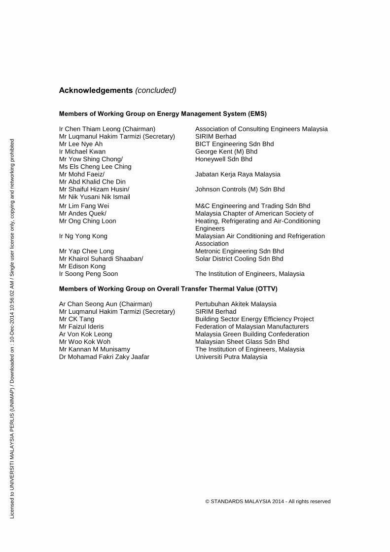
© STANDARDS MALAYSIA 2014 - All rights reserved
11D062R
2
Acknowledgements (concluded) Members of Working Group on Energy Management System (EMS) Name Organisation Ir Chen Thiam Leong (Chairman) Association of Consulting Engineers Malaysia Mr Luqmanul Hakim Tarmizi (Secretary) SIRIM Berhad Mr Lee Nye Ah BICT Engineering Sdn Bhd Ir Michael Kwan George Kent (M) Bhd Mr Yow Shing Chong/ Ms Els Cheng Lee Ching
Honeywell Sdn Bhd
Mr Mohd Faeiz/ Mr Abd Khalid Che Din
Jabatan Kerja Raya Malaysia
Mr Shaiful Hizam Husin/ Mr Nik Yusani Nik Ismail
Johnson Controls (M) Sdn Bhd
Mr Lim Fang Wei M&C Engineering and Trading Sdn Bhd Mr Andes Quek/ Mr Ong Ching Loon
Malaysia Chapter of American Society of Heating, Refrigerating and Air-Conditioning Engineers
Ir Ng Yong Kong Malaysian Air Conditioning and Refrigeration Association
Mr Yap Chee Long Metronic Engineering Sdn Bhd Mr Khairol Suhardi Shaaban/ Mr Edison Kong
Solar District Cooling Sdn Bhd
Ir Soong Peng Soon The Institution of Engineers, Malaysia Members of Working Group on Overall Transfer Thermal Value (OTTV) Name Organisation Ar Chan Seong Aun (Chairman) Pertubuhan Akitek Malaysia Mr Luqmanul Hakim Tarmizi (Secretary) SIRIM Berhad Mr CK Tang Building Sector Energy Efficiency Project Mr Faizul Ideris Federation of Malaysian Manufacturers
Ar Von Kok Leong Malaysia Green Building Confederation
Mr Woo Kok Woh Malaysian Sheet Glass Sdn Bhd Mr Kannan M Munisamy The Institution of Engineers, Malaysia Dr Mohamad Fakri Zaky Jaafar Universiti Putra Malaysia
Lice
nsed
to U
NIV
ER
SIT
I MA
LAY
SIA
PE
RLI
S (
UN
IMA
P)
/ Dow
nloa
ded
on :
10-D
ec-2
014
10:5
6:02
AM
/ S
ingl
e us
er li
cens
e on
ly, c
opyi
ng a
nd n
etw
orki
ng p
rohi
bite
d
© Copyright 2014 All rights reserved. No part of this publication may be reproduced or utilised in any form or by any means, electronic or mechanical, including photocopying and microfilm, without permission in writing from the Department of Standards Malaysia.
Lice
nsed
to U
NIV
ER
SIT
I MA
LAY
SIA
PE
RLI
S (
UN
IMA
P)
/ Dow
nloa
ded
on :
10-D
ec-2
014
10:5
6:02
AM
/ S
ingl
e us
er li
cens
e on
ly, c
opyi
ng a
nd n
etw
orki
ng p
rohi
bite
d