Embed Size (px)
Citation preview

High Linearity Mixer 5 - 35 GHz
Rev. V1
MAMX-011021
1 1
M/A-COM Technology Solutions Inc. (MACOM) and its affiliates reserve the right to make changes to the product(s) or information contained herein without notice. Visit www.macom.com for additional data sheets and product information.
For further information and support please visit: https://www.macom.com/support
1
Features
Passive Frequency Mixer
Conversion Loss: 8 dB @ 12 GHz
High IIP3: 23 dBm @ 12 GHz
RF Frequency: 5 - 35 GHz
LO Frequency: 3 - 33 GHz
IF Frequency: DC - 4.5 GHz
Lead-Free 1.5 x 1.2 mm TDFN 6-lead Package
Halogen-Free “Green” Mold Compound
RoHS* Compliant
Description
The MAMX-011021 is a passive mixer “engine” assembled in a 1.5 x 1.2 mm TDFN 6-lead plastic package. This device is designed for more linear applications such as high bit rate transmitters and receivers which may be used in Point-to-Point, Satcom or LAN applications. The mixer has 8 dB of conversion loss and 23 dBm of input intercept point (IIP3). This mixer can be used for either lower sideband (LSB) or upper sideband (USB) mixing. Two of these mixers can be combined in a quadrature configuration for image rejection. Positive bias voltage (< 1 V) can be applied to the LO or the VG (optional) pin to reduce LO drive requirements. The VG pin is internally bypassed. Positive bias voltage (< 1 V) can also be applied to the IF pin to optimize device linearity.
Ordering Information1,2
Part Number Package
MAMX-011021-TR1000 1000 piece reel
MAMX-011021-TR3000 3000 piece reel
MAMX-011021-SMB Sample Board
* Restrictions on Hazardous Substances, European Union Directive 2011/65/EU.
Functional Schematic
Pin Configuration3
1. Reference Application Note M513 for reel size information. 2. All sample boards include 5 loose parts.
Pin No. Pin Name Description
1 RF RF Port
2 N/C No Connection
3 IF (VD) IF Port
(optional Drain Voltage)
4 VG Gate Voltage (optional)
5 N/C No Connection
6 LO (VG) LO Port
(optional Gate Voltage)
7 Paddle4 Ground
3. MACOM recommends connecting No Connection pins to ground.
4. The exposed pad centered on the package bottom must be connected to RF, DC and thermal ground.
1
2
3
6
5
4
RF
N/C
IF
(VD)
LO
(VG)
N/C
VG

High Linearity Mixer 5 - 35 GHz
Rev. V1
MAMX-011021
2 2
M/A-COM Technology Solutions Inc. (MACOM) and its affiliates reserve the right to make changes to the product(s) or information contained herein without notice. Visit www.macom.com for additional data sheets and product information.
For further information and support please visit: https://www.macom.com/support
2
Electrical Specifications: TA = +25°C, VD = open, VG = open, Z0 = 50 Ω, IF Freq. = 2 GHz, LO Drive = 14 dBm @ 10 GHz, RF Freq. = 12 GHz
Absolute Maximum Ratings5,6
Parameter Absolute Maximum
Input Power 22 dBm
Drain Voltage 2 V
Gate Voltage 1 V
Junction Temperature7 +150°C
Operating Temperature -40°C to +85°C
Storage Temperature -65°C to +150°C
5. Exceeding any one or combination of these limits may cause permanent damage to this device.
6. MACOM does not recommend sustained operation near these survivability limits.
7. Operating at nominal conditions with TJ ≤ +150°C will ensure
MTTF > 1 x 10⁶ hours.
Parameter Test Conditions Units Min. Typ. Max.
Conversion Loss 6 GHz 12 GHz 30 GHz
dB — 9.5 8.0 8.5
— 9.0 —
RF Return Loss 5 - 35 GHz dB — 8 —
LO Return Loss 5 - 35 GHz dB — 10 —
IF Return Loss DC - 4.5 GHz dB — 12 —
Input P1dB — dBm — 15 —
Input IP3 PIN = -15 dBm dBm — 23 —
Handling Procedures
Please observe the following precautions to avoid damage:
Static Sensitivity
Gallium Arsenide Integrated Circuits are sensitive to electrostatic discharge (ESD) and can be damaged by static electricity. Proper ESD control techniques should be used when handling these Class 1A (HBM) devices.
High Linearity Mixer 5 - 35 GHz
Rev. V1
MAMX-011021
3 3
M/A-COM Technology Solutions Inc. (MACOM) and its affiliates reserve the right to make changes to the product(s) or information contained herein without notice. Visit www.macom.com for additional data sheets and product information.
For further information and support please visit: https://www.macom.com/support
3
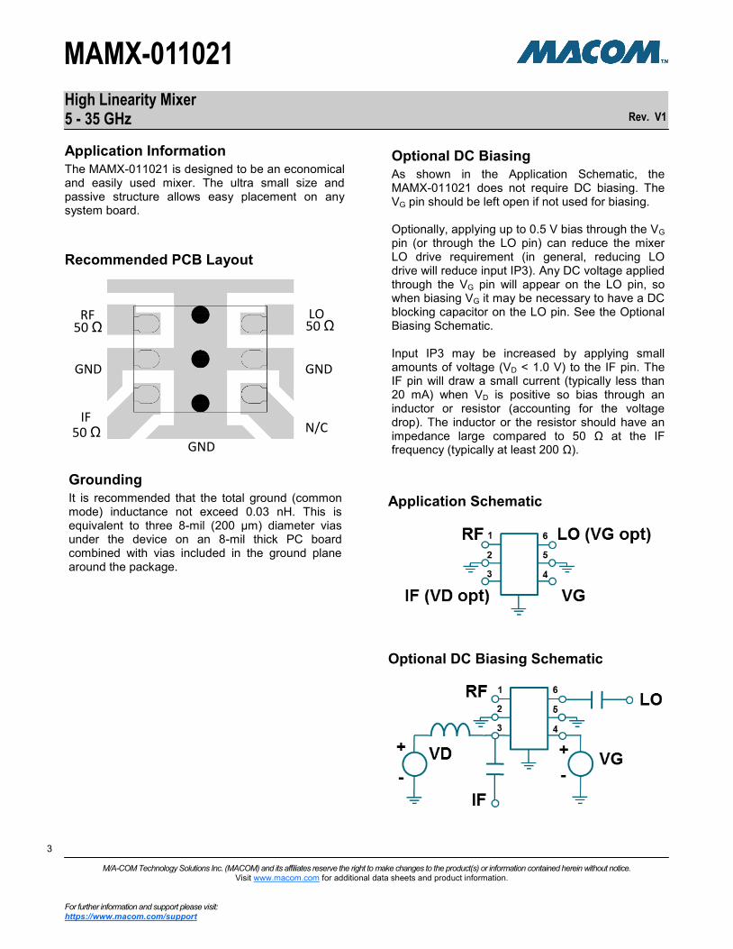
Application Schematic
Application Information
The MAMX-011021 is designed to be an economical and easily used mixer. The ultra small size and passive structure allows easy placement on any system board.
Optional DC Biasing
As shown in the Application Schematic, the MAMX-011021 does not require DC biasing. The VG pin should be left open if not used for biasing. Optionally, applying up to 0.5 V bias through the VG pin (or through the LO pin) can reduce the mixer LO drive requirement (in general, reducing LO drive will reduce input IP3). Any DC voltage applied through the VG pin will appear on the LO pin, so when biasing VG it may be necessary to have a DC blocking capacitor on the LO pin. See the Optional Biasing Schematic. Input IP3 may be increased by applying small amounts of voltage (VD < 1.0 V) to the IF pin. The IF pin will draw a small current (typically less than 20 mA) when VD is positive so bias through an inductor or resistor (accounting for the voltage drop). The inductor or the resistor should have an impedance large compared to 50 Ω at the IF frequency (typically at least 200 Ω).
Optional DC Biasing Schematic
Recommended PCB Layout
GND50 Ω
50 ΩRF
IF
50 ΩLO
GND GND
N/C
Grounding
It is recommended that the total ground (common mode) inductance not exceed 0.03 nH. This is equivalent to three 8-mil (200 µm) diameter vias under the device on an 8-mil thick PC board combined with vias included in the ground plane around the package.

High Linearity Mixer 5 - 35 GHz
Rev. V1
MAMX-011021
4 4
M/A-COM Technology Solutions Inc. (MACOM) and its affiliates reserve the right to make changes to the product(s) or information contained herein without notice. Visit www.macom.com for additional data sheets and product information.
For further information and support please visit: https://www.macom.com/support
4
Typical Performance Curves: Down Conversion, RF = -20 dBm, LO = 14 dBm, IF = 2 GHz, VG = open, ZO = 50 Ω, (unless otherwise noted)
Isolation
Conversion Gain (down)
Input IP3
Conversion Gain (up)
Gain vs. IF Frequency
Input P1dB
-20
-15
-10
-5
0
0 10 20 30 40
+25°C-40°C+85°C
(dB
)
Frequency (GHz)
0
10
20
30
40
0 10 20 30 40
+25°C-40°C+85°C
(dB
m)
Frequency (GHz)
-20
-15
-10
-5
0
0 10 20 30 40
+25°C-40°C+85°C
(dB
)
Frequency (GHz)
0
5
10
15
20
0 10 20 30 40
+25°C-40°C+85°C
(dB
m)
Frequency (GHz)
-60
-45
-30
-15
0
0 10 20 30 40
LO - IF
LO - RF
(dB
)
Frequency (GHz)
-25
-20
-15
-10
-5
0
0 2 4 6 8 10
LO - 5 GHzLO - 12 GHzLO - 20 GHz
(dB
)
IF Frequency (GHz)

High Linearity Mixer 5 - 35 GHz
Rev. V1
MAMX-011021
5 5
M/A-COM Technology Solutions Inc. (MACOM) and its affiliates reserve the right to make changes to the product(s) or information contained herein without notice. Visit www.macom.com for additional data sheets and product information.
For further information and support please visit: https://www.macom.com/support
5
Input IP3 over Temperature, VD = 0.5 V
Conversion Gain (LSB) vs. LO Drive Input IP2 vs. LO Drive
Input P1dB vs. LO Drive
Input IP3 vs. Optional VD
Input IP3 vs. LO Drive
Typical Performance Curves: Down Conversion, RF = -20 dBm, LO = 14 dBm, IF = 2 GHz, VG = open, ZO = 50 Ω, (unless otherwise noted)
-20
-15
-10
-5
0
0 10 20 30 40
LO = +12 dBmLO = +14 dBmLO = +16 dBm
(dB
)
Frequency (GHz)
0
20
40
60
80
0 10 20 30 40
LO = +12 dBmLO = +14 dBmLO = +16 dBm
(dB
m)
Frequency (GHz)
0
5
10
15
20
0 10 20 30 40
LO = +12 dBmLO = +14 dBmLO = +16 dBm
(dB
m)
Frequency (GHz)
0
10
20
30
40
0 10 20 30 40
LO = +12 dBmLO = +14 dBmLO = +16 dBm
(dB
m)
Frequency (GHz)
0
10
20
30
40
0 10 20 30 40
VD = 0.00 VVD = 0.25 VVD = 0.50 VVD = 0.75 V
(dB
m)
Frequency (GHz)
0
10
20
30
40
0 10 20 30 40
+25°C-40°C+85°C
(dB
)
Frequency (GHz)

High Linearity Mixer 5 - 35 GHz
Rev. V1
MAMX-011021
6 6
M/A-COM Technology Solutions Inc. (MACOM) and its affiliates reserve the right to make changes to the product(s) or information contained herein without notice. Visit www.macom.com for additional data sheets and product information.
For further information and support please visit: https://www.macom.com/support
6
Conversion Gain, LO = 1 GHz, VG = 0.28 V
RF Port Return Loss vs. Frequency LO Port Return Loss vs. Frequency
IF Port Return Loss vs. Frequency Down Conversion Gain vs. LO Drive and Optional VG
Typical Performance Curves: Down Conversion, TA = +25°C, RF = -20 dBm, LO = 14 dBm, IF = 2 GHz, VG = open, ZO = 50 Ω, (unless otherwise noted)
MxN Spurious Rejection at IF Port (dBc IF)
mRF
nLO
1 2 3 4 0
0 -3 30 24 31 xx
1 0 27 43 42 17
2 73 48 59 79 69
3 78 81 82 83 76
4 72 81 82 81 71
-20
-15
-10
-5
0
0 10 20 30 40
(dB
)
Frequency (GHz)
-20
-15
-10
-5
0
0 10 20 30 40
(dB
)
Frequency (GHz)
-40
-30
-20
-10
0
0 2 4 6 8 10
LO = 5 GHzLO = 12 GHzLO = 20 GHz
(dB
)
IF Frequency (GHz)
-20
-15
-10
-5
0
0 5 10 15 20
VG = 0.0 VVG = 0.2 VVG = 0.4 V
(dB
)
LO Power (dBm)
-20
-15
-10
-5
0
0 10 20 30 40
VD = 0.0 VVD = 0.5 V
(dB
)
Frequency (GHz)
High Linearity Mixer 5 - 35 GHz
Rev. V1
MAMX-011021
7 7
M/A-COM Technology Solutions Inc. (MACOM) and its affiliates reserve the right to make changes to the product(s) or information contained herein without notice. Visit www.macom.com for additional data sheets and product information.
For further information and support please visit: https://www.macom.com/support
7
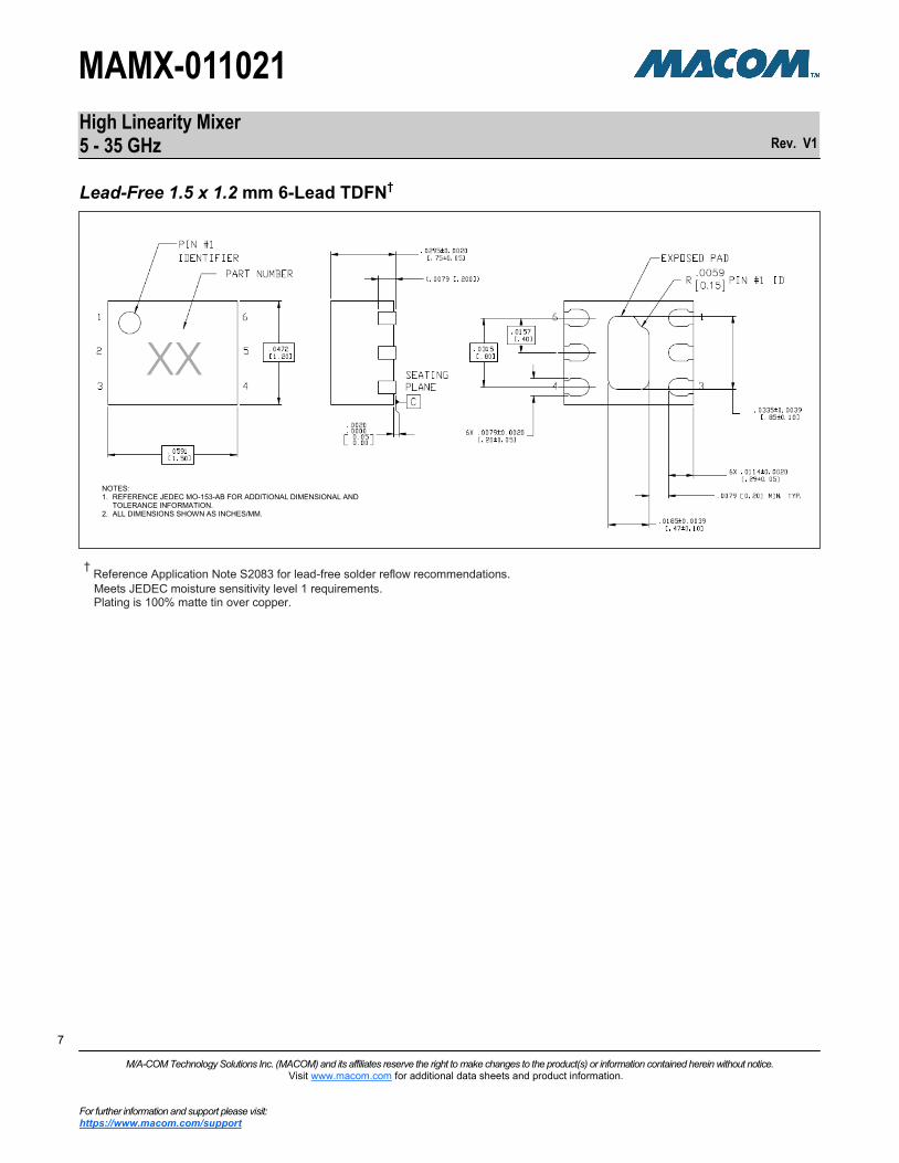
† Reference Application Note S2083 for lead-free solder reflow recommendations.
Meets JEDEC moisture sensitivity level 1 requirements. Plating is 100% matte tin over copper.
Lead-Free 1.5 x 1.2 mm 6-Lead TDFN†
NOTES: 1. REFERENCE JEDEC MO-153-AB FOR ADDITIONAL DIMENSIONAL AND
TOLERANCE INFORMATION. 2. ALL DIMENSIONS SHOWN AS INCHES/MM.

High Linearity Mixer 5 - 35 GHz
Rev. V1
MAMX-011021
8 8
M/A-COM Technology Solutions Inc. (MACOM) and its affiliates reserve the right to make changes to the product(s) or information contained herein without notice. Visit www.macom.com for additional data sheets and product information.
For further information and support please visit: https://www.macom.com/support
8
Applications Section
System usage of this Mixer
The MAMX-011021 may be used in single ended, balanced, and image reject circuit configurations.
Single Ended Mixer
Internally the MAMX-011021 is a single ended mixer. One disadvantage of a single ended mixer is the minimal LO rejection at the IF and RF ports. Multiple MAMX-011021 mixers can be combined with baluns or 90° hybrids to produce balanced mixers or image reject mixers. Generally these configurations will have an improved IP3 and greater rejection of unwanted frequencies.
Balanced Mixer
The balanced mixer will improve mixer performance by cancelling the LO at the IF output and cancelling RF second order products. Linearity will be improved by using two mixers and RF loss will be limited to the 180° hybrid and transformer insertion losses. LO drive requirements will be increased 3dB by the need to drive a second mixer. Also, the 0° hybrid losses must be added to the LO drive. An LO buffer such as a MACOM MAAM-011100 or MAAM-011109 may be used to allow a lower power LO source.
Image Reject Mixer
An image reject mixer can constructed from two MAMX-011021 mixers, a 0° hybrid and two 90° hybrids. The connection of the IF 90° hybrid ports determines if the upper or lower sideband RF signal is passed to the IF and the corresponding image is rejected. Similar to the balanced mixer a 3 dB LO power increase is required because of the second mixer. Buffer amplifiers such as a MACOM MAAM-011100 or MAAM-011109 may be used to provide the additional power.