Embed Size (px)
Citation preview

Ope
ratin
g M
anua
lD-R 290
Dust Concentration and Opacity Monitor of the Second
Generation
GmbH • Kollaustraße 105 • 22453 Hamburg • Germany • www.durag.com
Before starting any work please read the operating manual!
Article no.:4 009 352

Version: 10009568-11-03 Previous version: 10009568-10-03
Production date: 18/07/2016
Volume: 202
Operating manual Dust and Opacity Monitor D‑R 290
DURAG GmbHKollaustraße 10522453 HamburgGermany
Telephone:Fax:Email:Internet:
+49 (40) 55 42 18 – 0+49 (40) 58 41 [email protected]
This manual...● always relates to the complete device, even if individual program modules or parts have not been purchased.● or parts thereof may not be reproduced or distributed without express permission from DURAG GmbH, irre
spective of how this is done, in what language or by what medium, electronic or mechanical.● relates to the current design of the device at the time of this documentation being updated (see page 2 above
for production date).● contains figures which may differ due to further technical developments or to the manageable scale of their
actual appearance. No claims regarding the supply of identical products can therefore be derived from the illustrations shown.

Contents
D-R 290 3
Contents1 General 131.1 Information on this manual.............................................................................................................. 131.2 Explanation of symbols.................................................................................................................... 141.3 Limitation of liability......................................................................................................................... 151.4 Instructions regarding warranty....................................................................................................... 161.5 Spare parts...................................................................................................................................... 161.6 Customer service............................................................................................................................. 161.7 Copyright ........................................................................................................................................ 161.8 Trademarks..................................................................................................................................... 17
2 Safety 212.1 General safety instructions.............................................................................................................. 212.2 Designated use................................................................................................................................ 222.3 Responsibility of the operating company......................................................................................... 222.4 Personnel........................................................................................................................................ 222.4.1 Personnel, skills............................................................................................................................... 222.4.2 Unauthorised personnel.................................................................................................................. 232.5 Personal protective equipment........................................................................................................ 242.6 Basic hazards.................................................................................................................................. 242.6.1 Hazards due to electrical equipment............................................................................................... 242.6.2 Hazard due to hot, aggressive or explosive gases or high pressure of the measuring gas............ 252.6.3 Hazard due to automatic closing mechanisms................................................................................ 252.6.4 Avoidance of consequential damage in the event of a system fault................................................ 262.7 Device-specific hazards and safety measures................................................................................ 262.7.1 Hazard to the device due to purge air failure................................................................................... 262.8 Description and location of safety equipment and emergency stop mechanisms........................... 27
3 Delivery 313.1 Delivery information......................................................................................................................... 313.2 Transportation, packaging and storage........................................................................................... 313.2.1 Safety instructions for transport....................................................................................................... 313.2.2 Incorrect transport........................................................................................................................... 313.2.3 Transport inspection........................................................................................................................ 313.2.4 Packaging........................................................................................................................................ 323.2.5 Storage conditions........................................................................................................................... 323.3 Scope of supply............................................................................................................................... 333.3.1 Standard scope of supply................................................................................................................ 333.3.2 Optional equipment......................................................................................................................... 343.3.3 Reflectors........................................................................................................................................ 363.3.4 Optional version variants................................................................................................................. 37
4 Product description 414.1 Fundamental features...................................................................................................................... 414.2 Device and Function description..................................................................................................... 414.2.1 Principle of operation....................................................................................................................... 424.2.2 Measurement principle.................................................................................................................... 454.2.3 Transmission................................................................................................................................... 464.2.4 Opacity............................................................................................................................................ 464.2.5 Calculation of the opacity at the flue stack opening........................................................................ 464.2.6 Optical density (extinction).............................................................................................................. 484.2.7 Calculation of the dust concentration.............................................................................................. 48

Contents
4 D-R 290
4.3 System components........................................................................................................................ 504.3.1 Possible system configurations....................................................................................................... 514.4 Applications, Designated use.......................................................................................................... 534.5 Conformity/approval........................................................................................................................ 544.6 Designation of device components for the D-R 290........................................................................ 544.7 Identification of the product............................................................................................................. 574.7.1 Information about the type label...................................................................................................... 59
5 Installation 635.1 Safety.............................................................................................................................................. 635.1.1 Transport to the place of installation................................................................................................ 645.1.2 Skill levels of personnel for installation and commissioning............................................................ 645.2 Preparation for installation............................................................................................................... 645.2.1 Preconditions for operation.............................................................................................................. 665.2.2 Instructions for planning the electrical connections to the system................................................... 665.2.3 Instructions for selection the device variant and measuring point................................................... 675.2.4 Free space around the device housing........................................................................................... 695.3 System installation sequence :........................................................................................................ 695.4 Installation of the D−R 290 measuring head and reflector ............................................................. 705.4.1 Standard installation of the welded-in pipes with adjustment flanges............................................. 705.4.2 Installation variants.......................................................................................................................... 735.4.3 Alignment of the tube stubs............................................................................................................. 765.4.4 Installation of the measuring head and reflector.............................................................................. 765.4.5 Electrical connections to the measuring head................................................................................. 795.4.6 Meaning of the LEDs....................................................................................................................... 805.4.7 Configuration of the relay outputs.................................................................................................... 815.5 Installation of the D-SK 290 protective device ................................................................................ 835.5.1 Installation sequence for the measuring head and reflector (when the D-SK 290 protective device is
used)................................................................................................................................................ 845.5.2 Display LEDs of the control electronics........................................................................................... 875.5.3 Installation protective device D-SK 290........................................................................................... 875.5.4 D-SK AE electrical connection......................................................................................................... 885.5.5 Configuring the protective device.................................................................................................... 925.5.6 Checking the protective device........................................................................................................ 925.5.7 Commissioning the D-SK AE........................................................................................................... 935.6 Installation of the D-ISC 100 control unit......................................................................................... 965.6.1 Connecting the supply and control unit........................................................................................... 965.7 Installation of the supply unit........................................................................................................... 975.7.1 Installation of the D-TB 100 supply unit........................................................................................... 975.7.2 Electrical connection to the D-TB 100 supply unit........................................................................... 985.8 Installation of the purge air unit..................................................................................................... 1015.8.1 Selection of an installation location of the purge air unit (blower)................................................. 1015.8.2 Arrangement and installation of the purge air unit......................................................................... 1015.8.3 Electrical installation of the purge air unit...................................................................................... 1025.8.4 Electrical connection for the purge air motor................................................................................. 1025.9 Active operation............................................................................................................................. 1035.10 Dismantling and disposal............................................................................................................... 1035.10.1 Dismantling.................................................................................................................................... 1035.10.2 Disposal of the Dust Concentration and Opacity Monitor.............................................................. 1045.10.3 RoHS compliance.......................................................................................................................... 104
6 Commissioning 1076.1 Optical alignment........................................................................................................................... 107
Contents
D-R 290 5
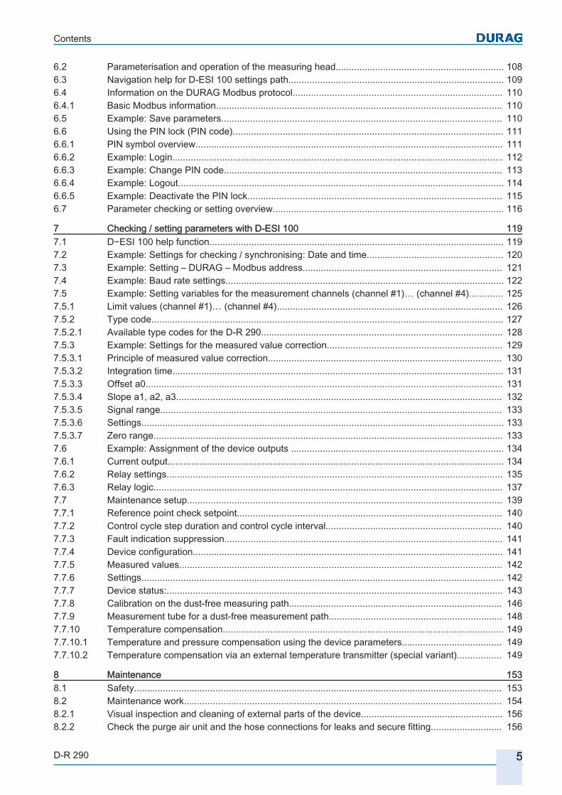
6.2 Parameterisation and operation of the measuring head................................................................ 1086.3 Navigation help for D-ESI 100 settings path.................................................................................. 1096.4 Information on the DURAG Modbus protocol................................................................................ 1106.4.1 Basic Modbus information............................................................................................................. 1106.5 Example: Save parameters........................................................................................................... 1106.6 Using the PIN lock (PIN code)....................................................................................................... 1116.6.1 PIN symbol overview..................................................................................................................... 1116.6.2 Example: Login.............................................................................................................................. 1126.6.3 Example: Change PIN code.......................................................................................................... 1136.6.4 Example: Logout............................................................................................................................ 1146.6.5 Example: Deactivate the PIN lock................................................................................................. 1156.7 Parameter checking or setting overview........................................................................................ 116
7 Checking / setting parameters with D‑ESI 100 1197.1 D−ESI 100 help function................................................................................................................ 1197.2 Example: Settings for checking / synchronising: Date and time.................................................... 1207.3 Example: Setting – DURAG – Modbus address............................................................................ 1217.4 Example: Baud rate settings.......................................................................................................... 1227.5 Example: Setting variables for the measurement channels (channel #1)… (channel #4)............. 1257.5.1 Limit values (channel #1)… (channel #4)...................................................................................... 1267.5.2 Type code...................................................................................................................................... 1277.5.2.1 Available type codes for the D-R 290............................................................................................ 1287.5.3 Example: Settings for the measured value correction................................................................... 1297.5.3.1 Principle of measured value correction......................................................................................... 1307.5.3.2 Integration time.............................................................................................................................. 1317.5.3.3 Offset a0........................................................................................................................................ 1317.5.3.4 Slope a1, a2, a3............................................................................................................................ 1327.5.3.5 Signal range.................................................................................................................................. 1337.5.3.6 Settings.......................................................................................................................................... 1337.5.3.7 Zero range..................................................................................................................................... 1337.6 Example: Assignment of the device outputs ................................................................................. 1347.6.1 Current output................................................................................................................................ 1347.6.2 Relay settings................................................................................................................................ 1357.6.3 Relay logic..................................................................................................................................... 1377.7 Maintenance setup........................................................................................................................ 1397.7.1 Reference point check setpoint..................................................................................................... 1407.7.2 Control cycle step duration and control cycle interval................................................................... 1407.7.3 Fault indication suppression.......................................................................................................... 1417.7.4 Device configuration...................................................................................................................... 1417.7.5 Measured values........................................................................................................................... 1427.7.6 Settings.......................................................................................................................................... 1427.7.7 Device status:................................................................................................................................ 1437.7.8 Calibration on the dust-free measuring path................................................................................. 1467.7.9 Measurement tube for a dust-free measurement path.................................................................. 1487.7.10 Temperature compensation........................................................................................................... 1497.7.10.1 Temperature and pressure compensation using the device parameters...................................... 1497.7.10.2 Temperature compensation via an external temperature transmitter (special variant)................. 149
8 Maintenance 1538.1 Safety............................................................................................................................................ 1538.2 Maintenance work......................................................................................................................... 1548.2.1 Visual inspection and cleaning of external parts of the device...................................................... 1568.2.2 Check the purge air unit and the hose connections for leaks and secure fitting........................... 156

List of figures
6 D-R 290
8.2.3 Checking and changing the filter................................................................................................... 1568.2.4 Cleaning the outer glass and the zero-point reflector:................................................................... 1578.2.5 Removing deposits from the welded-in pipes................................................................................ 1588.2.6 Checking the linearity.................................................................................................................... 1588.2.7 Zero point check............................................................................................................................ 1618.2.8 Contamination check..................................................................................................................... 1618.2.9 Reference point check................................................................................................................... 1628.2.10 Control cycle.................................................................................................................................. 1628.2.11 Functional test of the fail-safe shutter............................................................................................ 1638.2.12 Checking the battery in the measuring head................................................................................. 1648.3 Error messages / troubleshooting.................................................................................................. 167
9 Appendix 1779.1 Measurement point questionnaire................................................................................................. 1779.2 D-R 290 technical data ................................................................................................................. 1799.2.1 D-R 290 application data............................................................................................................... 1799.2.2 D-R 290 measuring head and reflector......................................................................................... 1799.2.3 D-SK AE control electronics protective device.............................................................................. 1809.2.4 D-SK 290 MA fail-safe shutter protective device........................................................................... 1809.2.5 D-TB 100 supply unit (terminal box).............................................................................................. 1819.2.6 D-BL XXX purge air unit ............................................................................................................... 1819.3 Dimensional diagrams................................................................................................................... 1829.3.1 Dimensional diagram of the measuring head/reflector.................................................................. 1829.3.2 Dimensional diagram of the measuring head/reflector with fail-safe shutter................................. 1849.3.3 Dimensional diagram of the welded-in pipe with adjustment flange.............................................. 1859.3.4 Dimensional diagram of the control electronics D-SK AE............................................................. 1869.3.5 Dimensional diagram fail-safe shutter D-SK MA........................................................................... 1879.3.6 Dimensional diagram supply unit (terminal box) D-TB 100........................................................... 1879.3.7 Dimensional diagram purge air unit D-BL...................................................................................... 1889.3.8 Dimensional diagram (optional) weather protection covers........................................................... 191
10 Glossary 195
11 Index 197
List of figuresFig. 4.1 System components..................................................................................................................... 42Fig. 4.2 Measurement............................................................................................................................... 43Fig. 4.3 Turntable plate............................................................................................................................. 43Fig. 4.4 Comparison measurement........................................................................................................... 43Fig. 4.5 Zero point measurement.............................................................................................................. 44Fig. 4.6 Reference point measurement..................................................................................................... 45Fig. 4.7 Measurement principle................................................................................................................. 45Fig. 4.8 Relationship between extinction, transmission and opacity......................................................... 46Fig. 4.9 Reference points for determination of the opacity........................................................................ 47Fig. 4.10 System components..................................................................................................................... 50Fig. 4.11 Dimensional diagram D−R 290 standard welded-in pipe with adjustment flange (↘= red dot).... 52Fig. 4.12 type label...................................................................................................................................... 59Fig. 5.1 System layout (example).............................................................................................................. 65Fig. 5.2 Measuring point............................................................................................................................ 68

List of figures
D-R 290 7
Fig. 5.3 Installation example on a horizontal duct..................................................................................... 69Fig. 5.4 Standard welded-in pipe with adjustment flange.......................................................................... 71Fig. 5.5 Standard installation of a welded-in pipe with adjustment flange................................................. 72Fig. 5.6 Installation of a welded-in pipe with adjustment flange in a brick stack....................................... 73Fig. 5.7 Installation of a welded-in pipe with adjustment flange on a gusset plate.................................... 74Fig. 5.8 Installation of a welded-in pipe with adjustment flange in a double-walled flue........................... 75Fig. 5.9 Alignment of the tube stubs.......................................................................................................... 76Fig. 5.10 Installation at the adjustment flange, dimensional diagram D−R 290.......................................... 78Fig. 5.11 Adjustable attachment.................................................................................................................. 79Fig. 5.12 Connection plugs and sockets on the underside of the housing.................................................. 80Fig. 5.13 (LEDs in the measuring head)...................................................................................................... 81Fig. 5.14 Attachment screws for thehousing cover..................................................................................... 82Fig. 5.15 Undo............................................................................................................................................. 82Fig. 5.16 Position of the switches SW1 and 2 in the measuring head........................................................ 82Fig. 5.17 Tightening..................................................................................................................................... 83Fig. 5.18 Installation at the adjustment flange, dimensional diagram D−R 290.......................................... 85Fig. 5.19 Adjustable attachment.................................................................................................................. 86Fig. 5.20 Control electronics displays.......................................................................................................... 87Fig. 5.21 Air flow sensor.............................................................................................................................. 88Fig. 5.22 Electrical connection to the D-SK AE........................................................................................... 89Fig. 5.23 Connection of the fail-safe shutter to the 8-core plug cable of the measuring head.................... 91Fig. 5.24 Control electronics front panel...................................................................................................... 93Fig. 5.25 LED control electronics................................................................................................................ 94Fig. 5.26 D‑SK AE control electronics......................................................................................................... 95Fig. 5.27 Shutter motor................................................................................................................................ 95Fig. 5.28 Connecting the D−R 290 as an individual sensor to the D‑TB 100 supply unit............................ 96Fig. 5.29 Connecting the D−R 290 as an individual sensor directly to the D‑ISC 100 control unit.............. 96Fig. 5.30 Supplying the D−R 290 via a D-TB 100 and connection of a D‑ISC 100 via DURAG Bus.......... 97Fig. 5.31 Supply unit cover assembly.......................................................................................................... 98Fig. 5.32 Attaching the retaining plates....................................................................................................... 98Fig. 5.33 Connecting the cable screen........................................................................................................ 99Fig. 5.34 Connecting the cable.................................................................................................................... 100Fig. 5.35 D-TB 100 terminal box connection diagram................................................................................. 100Fig. 5.36 Junction box................................................................................................................................. 102Fig. 5.37 Electrical connection for the purge air motor................................................................................ 102Fig. 6.1 Sighting mechanism..................................................................................................................... 108Fig. 6.2 Optical alignment.......................................................................................................................... 108Fig. 6.3 Device list..................................................................................................................................... 109Fig. 6.4 PIN lock deactivated..................................................................................................................... 111Fig. 6.5 Login box...................................................................................................................................... 112Fig. 6.6 D-ESI 100 device overview page after login................................................................................ 113Fig. 6.7 D-ESI 100 device overview page after login................................................................................ 113Fig. 6.8 Change PIN Code box................................................................................................................. 114Fig. 6.9 End device locked with a PIN code.............................................................................................. 114Fig. 6.10 Deactivate the PIN code............................................................................................................... 115Fig. 6.11 PIN Code changed successfully................................................................................................... 115Fig. 6.12 PIN lock deactivated..................................................................................................................... 116Fig. 6.13 Change PIN code failed............................................................................................................... 116Fig. 7.1 Info about D−ESI 100................................................................................................................... 119Fig. 7.2 Setting the date/time.................................................................................................................... 120

List of figures
8 D-R 290
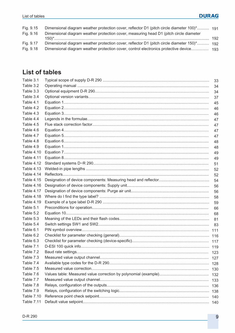
Fig. 7.3 Setting DURAG − Modbus address.............................................................................................. 121Fig. 7.4 Setting DURAG – Modbus communication settings .................................................................... 123Fig. 7.5 Setting variables for the measurement channels......................................................................... 125Fig. 7.6 Common parameters D‑R 290 Variables setting I........................................................................ 131Fig. 7.7 Diagram: Measured value correction by polynomial (example)................................................... 132Fig. 7.8 Common parameters D‑R 290 Variables setting II....................................................................... 133Fig. 7.9 Setting the analogue output......................................................................................................... 134Fig. 7.10 Setting relay setup........................................................................................................................ 136Fig. 7.11 Setting the relay settings.............................................................................................................. 138Fig. 7.12 Setting the maintenance settings................................................................................................. 139Fig. 7.13 Device configuration..................................................................................................................... 141Fig. 7.14 Measured values.......................................................................................................................... 142Fig. 7.15 Calibration.................................................................................................................................... 143Fig. 7.16 Device status................................................................................................................................ 144Fig. 7.17 Pin assignment or the purge air monitoring plug.......................................................................... 145Fig. 7.18 Connection plugs and sockets on the underside of the housing.................................................. 145Fig. 7.19 Quick Info explanation of the shutter status................................................................................. 145Fig. 7.20 Dust-free measurement................................................................................................................ 147Fig. 7.21 Diaphragm.................................................................................................................................... 148Fig. 7.22 Measurement tube for a smoke-free measurement path............................................................. 148Fig. 7.23 Temperaturetransmitter................................................................................................................ 149Fig. 7.24 Pin assignmentconnection , temperature transmitter................................................................... 150Fig. 7.25 Electrical connection of a 2-wire transducer (without its own power supply)............................... 150Fig. 7.26 Electrical connection of a 4-wire-transducer (with its own power supply).................................... 150Fig. 8.1 Purge air filter............................................................................................................................... 156Fig. 8.2 Optical surfaces............................................................................................................................ 157Fig. 8.3 EPA-Test filter.............................................................................................................................. 158Fig. 8.4 Insert the test filter into the device................................................................................................ 159Fig. 8.5 Example of a linearity test without scaling.................................................................................... 160Fig. 8.6 Example of a linearity test with scaling......................................................................................... 161Fig. 8.7 Turntable plate............................................................................................................................. 162Fig. 8.8 LED 5........................................................................................................................................... 164Fig. 8.9 Attachment screws for thehousing cover..................................................................................... 164Fig. 8.10 Undo............................................................................................................................................. 165Fig. 8.11 Changing the battery.................................................................................................................... 165Fig. 8.12 Tightening..................................................................................................................................... 166Fig. 9.1 Measurement point questionnaire 1............................................................................................. 177Fig. 9.2 Measurement point questionnaire 2............................................................................................. 178Fig. 9.3 Dimensional diagram of the measuring head/reflector................................................................. 182Fig. 9.4 Installation example on a horizontal duct..................................................................................... 183Fig. 9.5 Dimensional diagram of the measuring head/reflector with fail-safe shutter................................ 184Fig. 9.6 Installation example on a horizontal duct..................................................................................... 185Fig. 9.7 Dimensional diagram D−R 290 standard welded-in pipe with adjustment flange (↘= red dot).... 185Fig. 9.8 Housing D-SK AE dimensional diagram, space required............................................................. 186Fig. 9.9 Dimensional diagram housing D-SK 290 MA *D1 diameter 100 mm .......................................... 187Fig. 9.10 Dimensional diagram housing D-SK 280 MA *D1 diameter 150 mm .......................................... 187Fig. 9.11 Dimensional diagram D-TB 100 supply unit................................................................................. 188Fig. 9.12 Dimensional diagram purge air unit *D1 diameter 100 mm (*D1 see Welded-in pipe lengths )... 189Fig. 9.13 Dimensional diagram purge air unit *D1 diameter 150 mm (*D1 see Welded-in pipe lengths )... 190Fig. 9.14 Dimensional diagram weather protection cover, measuring head D1 (pitch circle diameter
100)*............................................................................................................................................. 191
List of tables
D-R 290 9
Fig. 9.15 Dimensional diagram weather protection cover, reflector D1 (pitch circle diameter 100)*........... 191Fig. 9.16 Dimensional diagram weather protection cover, measuring head D1 (pitch circle diameter
150)*............................................................................................................................................. 192Fig. 9.17 Dimensional diagram weather protection cover, reflector D1 (pitch circle diameter 150)*........... 192Fig. 9.18 Dimensional diagram weather protection cover, control electronics protective device................ 193
List of tablesTable 3.1 Typical scope of supply D‑R 290 ................................................................................................. 33Table 3.2 Operating manual ........................................................................................................................ 34Table 3.3 Optional equipment D‑R 290........................................................................................................ 34Table 3.4 Optional version variants.............................................................................................................. 37Table 4.1 Equation 1.................................................................................................................................... 45Table 4.2 Equation 2.................................................................................................................................... 46Table 4.3 Equation 3.................................................................................................................................... 46Table 4.4 Legends in the formulae............................................................................................................... 47Table 4.5 Flue stack correction factor.......................................................................................................... 47Table 4.6 Equation 4.................................................................................................................................... 47Table 4.7 Equation 5.................................................................................................................................... 47Table 4.8 Equation 6.................................................................................................................................... 48Table 4.9 Equation 1.................................................................................................................................... 48Table 4.10 Equation 7.................................................................................................................................... 49Table 4.11 Equation 8.................................................................................................................................... 49Table 4.12 Standard systems D−R 290......................................................................................................... 51Table 4.13 Welded-in pipe lengths ................................................................................................................ 52Table 4.14 Reflectors..................................................................................................................................... 52Table 4.15 Designation of device components: Measuring head and reflector.............................................. 54Table 4.16 Designation of device components: Supply unit........................................................................... 56Table 4.17 Designation of device components: Purge air unit....................................................................... 56Table 4.18 Where do I find the type label? .................................................................................................... 58Table 4.19 Example of a type label D‑R 290 ................................................................................................. 59Table 5.1 Preconditions for operation.......................................................................................................... 66Table 5.2 Equation 10.................................................................................................................................. 68Table 5.3 Meaning of the LEDs and their flash codes.................................................................................. 81Table 5.4 Switch settings SW1 and SW2..................................................................................................... 83Table 6.1 PIN symbol overview.................................................................................................................... 111Table 6.2 Checklist for parameter checking (general).................................................................................. 116Table 6.3 Checklist for parameter checking (device-specific)...................................................................... 117Table 7.1 D-ESI 100 quick info..................................................................................................................... 119Table 7.2 Baud rate settings........................................................................................................................ 123Table 7.3 Measured value output channel................................................................................................... 127Table 7.4 Available type codes for the D-R 290........................................................................................... 128Table 7.5 Measured value correction........................................................................................................... 130Table 7.6 Values table: Measured value correction by polynomial (example)............................................. 132Table 7.7 Measured value output channel................................................................................................... 133Table 7.8 Relays, configuration of the outputs............................................................................................. 136Table 7.9 Relays, configuration of the switching logic.................................................................................. 138Table 7.10 Reference point check setpoint.................................................................................................... 140Table 7.11 Default value setpoint................................................................................................................... 140

List of tables
10 D-R 290
Table 7.12 Specified values for control measurements................................................................................. 140Table 7.13 Default value for fault indication suppression .............................................................................. 141Table 7.14 Pin assignment of the 8-pin plug for purge air monitoring............................................................ 145Table 7.15 Pin assignment of the device socket for connection of the 4-20 mA temperature transmitter..... 150Table 8.1 Suggestion for checking and maintenance work.......................................................................... 155Table 8.2 List of messages for D‑R 290 ...................................................................................................... 167Table 8.3 List of warnings for the D‑R 290 .................................................................................................. 168Table 8.4 List of simple faults for the D‑R 290 ............................................................................................ 171Table 8.5 List of critical faults for the D‑R 290 ............................................................................................ 172Table 9.1 Technical data, D-R 290 application data.................................................................................... 179Table 9.2 Technical data, D-R 290 measuring head.................................................................................... 179Table 9.3 Technical data, D-R 290 reflector................................................................................................. 180Table 9.4 Technical data, D-SK AE control electronics protective device.................................................... 180Table 9.5 Technical data, D-SK 290 MA fail-safe shutter protective device................................................ 180Table 9.6 Technical data, D-TB 100 supply unit (terminal box)................................................................... 181Table 9.7 Technical data, D-BL xxx purge air unit....................................................................................... 181Table 9.8 Welded-in pipe lengths ................................................................................................................ 185

D-R 290Dust Concentration and Opacity Monitor of the
Second Generation
11 General
1.1 Information on this manual
1.2 Explanation of symbols
1.3 Limitation of liability
1.4 Instructions regarding warranty
1.5 Spare parts
1.6 Customer service
1.7 Copyright
1.8 Trademarks

12 D-R 290

1 | General
D-R 290 13
General
We hope that our products and services will make a significant contribution to your success. We will be delighted if the information provided in this publication achieves this.Should you require information that is not sufficiently covered in this document, please request the required information from the relevant agent of DURAG GmbH. Our Support & Service team is also available to answer any questions on DURAG GROUP products and services. Addresses and telephone numbers can be found on page DURAG GROUP company addresses.
If anything is not clear:Please contact the manufacturer! Obtain answers to your questions.
Information on the company and its products can also be found on the Internet at www.durag.de.
Information on this manual
This manual provides important information on how to use the D‑R 290. Compliance with all specified safety instructions and guidelines for behaviour is a prerequisite for safe working.In addition, the locally applicable accident prevention regulations and general safety requirements for the device and its application must also be complied with.
NOTICEBefore starting any work, read the Operating manual!Don't let ignorance lead to personal injuries and damage to the equipment.
In particular read the section 2 Safety [} 21] and the respective safety instructions in full.● This manual is an integral part of the product and must be kept in the immediate
vicinity of the device, accessible to all staff. Ensure compliance with the instructions set out for avoidance of hazards and damage.
This manual...● always relates to the complete device, even if individual program modules or parts
have not been purchased.● or parts thereof may not be reproduced or distributed without express permission
from DURAG GmbH, irrespective of how this is done, in what language or by what medium, electronic or mechanical.
● relates to the current design of the device at the time of this documentation being updated (see page 2 above for production date).
● contains figures which may differ due to further technical developments or to the manageable scale of their actual appearance. No claims regarding the supply of identical products can therefore be derived from the illustrations shown.
Unless otherwise stated: all measurements are in mm
1
1.1

1 | General
14 D-R 290
In order to make the text of this manual clear, text elements such as instructions, warnings, tips, keyboard symbols, menu addresses etc. are displayed in different ways. Warning notices are represented by symbols in this Operating manual. Instructions are introduced with key words that highlight the extent of the hazard.All instructions must be unconditionally and carefully observed to avoid accidents, personal injury and material damage.
DANGER...indicates an immediately hazardous situation that will lead to death or serious injury if not avoided.
WARNING...indicates a possible situation of danger that will lead to death or serious injury if not avoided.
CAUTION...indicates a possible situation of danger that can lead to minor or slight injury if not avoided.
CAUTION...indicates a situation that may result in material or environmental damage if not avoided.
Information or a tip is shown as follows:
... highlights useful tips and recommendations, as well as information aimed at ensuring efficient and fault-free operation.
Explanation of symbols
To draw attention to specific hazards, warning notices and signal words are used in conjunction with the following symbols:
General warning symbol
Caustic
Electric power Explosive atmosphere
Warning
Tips and Recommendations
1.2
Specific safety instructions
1 | General
D-R 290 15
Injuries to the hand Electrostatic sensitive devices (ESD)
Hot surface
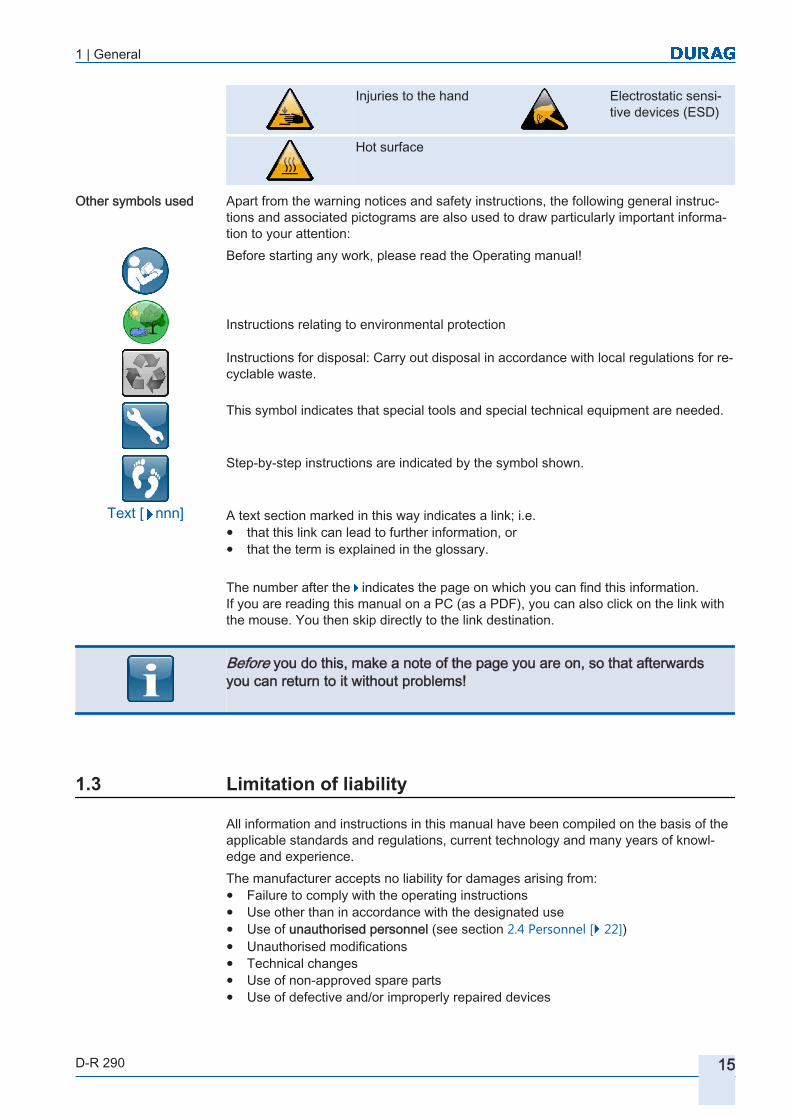
Apart from the warning notices and safety instructions, the following general instructions and associated pictograms are also used to draw particularly important information to your attention:Before starting any work, please read the Operating manual!
Instructions relating to environmental protection
Instructions for disposal: Carry out disposal in accordance with local regulations for recyclable waste.
This symbol indicates that special tools and special technical equipment are needed.
Step-by-step instructions are indicated by the symbol shown.
A text section marked in this way indicates a link; i.e.● that this link can lead to further information, or● that the term is explained in the glossary.
The number after the indicates the page on which you can find this information. If you are reading this manual on a PC (as a PDF), you can also click on the link with the mouse. You then skip directly to the link destination.
Before you do this, make a note of the page you are on, so that afterwards you can return to it without problems!
Limitation of liability
All information and instructions in this manual have been compiled on the basis of the applicable standards and regulations, current technology and many years of knowledge and experience.The manufacturer accepts no liability for damages arising from:● Failure to comply with the operating instructions● Use other than in accordance with the designated use● Use of unauthorised personnel (see section 2.4 Personnel [} 22])● Unauthorised modifications● Technical changes● Use of non-approved spare parts● Use of defective and/or improperly repaired devices
Other symbols used
Text [ nnn]
1.3

1 | General
16 D-R 290
Furthermore, the obligations agreed in the contract of sale, the general conditions of business ("Conditions of supply for goods and services in the electrical industry" (ZVEI)) and the manufacturer's Conditions of Supply, together with the statutory regulations in force at the date of signing the contract are all applicable.
Instructions regarding warranty
The terms of the warranty can be found as a separate document in the General Terms and Conditions of Business.Conversions and modifications to the device are not admissible. Any tampering with the device will invalidate the warranty.Fault-free and safe operation of the device depends on appropriate transportation, correct storage, installation and assembly, regular maintenance and also careful operation.
Spare parts
WARNING Risk of injury due to incorrect spare parts! Incorrect or defective spare parts can lead to damage, malfunctions or total failure and may also impair safety.
▶ Only use genuine spare parts supplied by the manufacturer.
▶ Spare parts can be obtained from an authorised agent or directly from the manufacturer.
Customer service
If anything is unclear, contact the manufacturer. Our Service Department is available to provide any technical information you may require.Information about responsible offices and partners can be obtained at any time over the Internet. For the manufacturer's addresses see page 2 or page DURAG GROUP company addresses.
Copyright
Keep this manual confidential. It is intended exclusively for personnel employed to use the device Passing it on to third parties without the written consent of the manufacturer is not permitted.The manual or parts of it may not be duplicated or transferred without the written consent of the manufacturer, nor translated into any other languages, irrespective of the method or means, whether electronically or mechanically.© DURAG GmbH 2015 All rights reserved.
The content, texts, drawings, pictures and other images contained in this document are protected by copyright and subject to industrial property rights. Any improper use is punishable by law.
1.4
1.5
1.6
1.7

1 | General
D-R 290 17
Trademarks
All additional program names and designations (such as Microsoft Windows and Excel) used in this manual may also be registered trademarks of their respective manufacturers and may not be used commercially or in any other way. Errors and omissions excepted.
1.8

1 | General
18 D-R 290

D-R 290Dust Concentration and Opacity Monitor of the
Second Generation
22 Safety
2.1 General safety instructions
2.2 Designated use
2.3 Responsibility of the operating company
2.4 Personnel2.4.1 Personnel, skills
2.4.2 Unauthorised personnel
2.5 Personal protective equipment
2.6 Basic hazards2.6.1 Hazards due to electrical equipment
2.6.2 Hazard due to hot, aggressive or explosive gases or high pressure of the measuring gas
2.6.3 Hazard due to automatic closing mechanisms
2.6.4 Avoidance of consequential damage in the event of a system fault
2.7 Device-specific hazards and safety measures2.7.1 Hazard to the device due to purge air failure
2.8 Description and location of safety equipment and emergency stop mechanisms

20 D-R 290

2 | Safety
D-R 290 21
Safety
Before starting any work, read the operating instructions!In this section we give you important instructions for your safety. We point out how you can avoid hazards that may affect the life and health of the personnel and cause damage to the device and other equipment. Compliance with these instructions contributes to problem-free operation.If you fail to take note of these instructions, the DURAG GmbH may not be made liable for damage caused as a result of negligent or intentional disregard of the information provided in these instructions!
General safety instructions
The product Dust and Opacity Monitor D‑R 290 from DURAG GmbH has been designed and built using state of the art technology and complies with the recognised safety regulations. Despite this, hazards can arise.Operate the product only when it is in good working order, and in compliance with the manual. Any abnormal change to normal operation should be taken seriously as an indication of impaired functionality.In this regard, pay attention to:● emission of smoke or unusual smells● unusual noises resulting from and during operation of the device (including for in
stance the purge air blower),● unusual vibrations,● excessive temperatures of system components,● changes in power consumption without obvious cause● the tripping of monitoring devices,● abnormal, strong fluctuations or shifts in the measurement results.Use other than in accordance with the designated use or handling can result in health hazards or material damage. Follow the instructions for all actions on the product D‑R 290 and the safety instructions and warnings in the individual sections of this manual.The following warnings and safety instructions apply in full to the product described:● When preparing and performing work:
Observe the legal requirements applicable for the system and the corresponding technical regulations. Comply with national safety and accident prevention regulations.
● Work in accordance with:… the local, plant-specific conditions, … hazards caused by operational processes … the specifications.
● This manual is an integral part of the product and must be kept in the immediate vicinity of the device, accessible to all staff. Ensure compliance with the instructions set out for avoidance of hazards and damage.
● Suitable protective mechanisms and personal protective equipment must be available in sufficient quantities and used by the personnel in accordance with the relevant potential hazards.
● The device may only be operated when in good working order, and in compliance with the safety instructions!
● The device as a whole and also its individual components may be used only when in their original configuration.
2
2.1

2 | Safety
22 D-R 290
● Maintenance work and repairs, other than those described in this manual, may not be performed without prior approval of the manufacturer.
Designated use
The designated use of the D‑R 290 is described in section 4.4 Applications, Designated use [} 53] !
Responsibility of the operating company
The device is intended for use in commercial operations. The operating company is therefore subject to the statutory health and safety obligations, together with the applicable directives, legislation and standards.In addition to the health and safety instructions contained in this manual, the safety regulations, accident prevention regulations and environmental protection regulations for the application in which the device is used must be complied with. The following rules in particular are applicable:● The operating company must inform itself about the applicable health and safety
regulations. In addition, a risk assessment must be performed which identifies the hazards arising in connection with the device under the special working conditions prevailing at the place of use. The results of the risk assessment must be converted into applicable operating instructions for the operation of the device.
● Throughout the period of use of the device, the operating company must check that the operating instructions they have written satisfy the latest issue of the regulations, and must update them as required.
● The operating company must clearly regulate and specify who has responsibility for installation, operation, maintenance and cleaning.
● The operating company must ensure that all employees who deal with the device have read and understood the operating instructions. In addition, at regular intervals it must train the personnel and inform them about the hazards.
● Furthermore operating company is responsible for ensuring that the device is in good technical condition at all times and that the necessary maintenance work has been performed.
● The operating company must provide the necessary protective equipment for personnel.
Personnel
Personnel, skills
WARNING Danger of injury due to insufficient skills!Incorrect use can result in serious personal injury and material damage.Only ever have work performed by suitably qualified specialised personnel.
This manual assumes that the personnel performing the work have the necessary training and knowledge. Only personnel who have this knowledge are considered to be qualified and authorised in this manual.For work on the D‑R 290 product, authorised personnel must have the following skills to which reference is made in this manual for the various activities:
2.2
2.3
2.4
2.4.1

2 | Safety
D-R 290 23
● Operatorsare those who have had operational training, including instruction in the operation of the productD‑R 290 Dust and Opacity Monitor and are in a position to perform the work assigned to them.
● Specialised personnelare those who because of their specialist training and experience, coupled with knowledge of the applicable regulations, are in a position to perform the work assigned to them and make independent judgements of the potential hazards.
● Electriciansare those who because of their specialist training and experience, coupled with knowledge of the applicable regulations, are in a position to perform work on electrical equipment and make independent judgements of the potential hazards. Specialised electricians are specifically trained for the working environment in which they operate, and they also know the local relevant standards and regulations. All electrical work may only be carried out by specialised electricians.
In addition, the operating company must ensure that the operators, specialised personnel and electricians are given up-to-date instructions on the following:● Precise knowledge of operational hazards and how to avoid them.● Knowledge of system conditions, applicable standards, regulations, directives, op
erating instructions and accident prevention regulations in the context of the work assigned to them.
● Potential hazards resulting from improper behaviour.● Sufficient knowledge of the D‑R 290 (Dust and Opacity Monitor).To acquire specialist knowledge of the device, DURAG offers appropriate courses.Information on these is available online on the DURAG website or by telephone (see the manufacturer's address on page 2).● Service technicians
because of their specialist training, knowledge and experience of the applicable standards and regulations are able to carry out work specifically on DURAG GROUP devices. Service technicians are employees of the DURAG GROUP or employees of DURAG GROUP partners. Service technicians have completed comprehensive education and training on these devices.In order to ensure compliance with special local provisions and plant regulations, local skilled personnel or an electrician should accompany them in their work as necessary.
Only persons who can be expected to perform their work reliably are accredited as personnel.Persons whose responsiveness is compromised by substances such as drugs, alcohol or medications will not be accredited.When selecting personnel, the specific regulations regarding age and professional qualifications at the operating site should be complied with.
Unauthorised personnel
WARNING Danger for unauthorised persons!Unauthorised persons who fail to comply with the requirements outlined here are not aware of the dangers inherent in the work area. Incorrect behaviour can lead to severe injury and damage.Therefore:
▶ Ensure that unauthorised personnel do not enter the working area.
▶ In case of doubt, approach personnel and instruct them to leave the working area.
▶ Stop all work if any unauthorised persons are in the working area.
2.4.2

2 | Safety
24 D-R 290
Personal protective equipment
During work, it may be necessary to wear personal protective equipment to minimise health hazards.Detailed specifications must be set out by the operating company, depending on the potential plant-specific hazards.● The protective equipment necessary for the relevant work must be worn at all
times.● Observe any signs with instructions relating to personal protective equipment in
the working area.● Do not wear any rings, chains or other jewellery when at work.
Basic hazards
This section sets out the remaining risks identified by the risk assessment.The information set out here and the safety instructions and warnings in the other sections of this manual must be adhered to, in order to prevent health hazards and hazardous situations.
Hazards due to electrical equipment
The personnel assigned to carry out installation, commissioning and maintenance must be thoroughly familiar with all potential hazards and repair measures as set out in this manual.
DANGER High voltage. Risk of fatal injury due to electric shock!Touching live parts poses an immediate risk of fatal injury. Damage to the insulation or to individual components can lead to fatal injury.
▶ If there is any damage to the insulation, switch off the power supply immediately and have it repaired.
▶ Permit only qualified electricians to work on electrical equipment.
▶ Before opening the casing of a device or removing a guard protecting against touching it, deenergise the device, test it to ensure it is electrically dead and secure it against switching on again.
▶ Keep moisture away from live components. This can lead to short circuits.
To avoid hazards:● Only connect the Dust and Opacity Monitor to the supply voltage set out on the
type label.● Do not connect the operating voltage and switch on until the device has been fully
installed. Once the operating voltage has been connected, the device is immediately ready for operation!
● Cables must be routed so as to exclude the possibility of potential accidents by people stumbling over them or becoming entangled in them.
This measuring system has been designed to ensure safe separation between primary and secondary electric circuits. Low voltages which are connected must therefore also be safely separated.
2.5
2.6
2.6.1

2 | Safety
D-R 290 25
NOTICE Damage to electronic components due to electrostatic discharge (ESD)Electronic components are becoming ever smaller and more complex. Their susceptibility to damage from electrostatic discharge is increased accordingly. To protect these components, measures must be undertaken to prevent electrostatic discharge during all work performed on the open device (ESD protection).To prevent the human body becoming charged with static electricity, service employees can for example be equipped with a personal earthing system.
Hazard due to hot, aggressive or explosive gases or high pressure of the measuring gas
Measurement and reflector units are directly mounted on the duct carrying the gas to be measured. If these devices become detached from the flange tube, gas can escape from the duct through the flange connection, particularly in the event of overpressure, and cause serious damage to health if maintenance personnel are unprotected. Therefore, before releasing the flange connection, always take appropriate protective measures, e.g. close the quick-release clamp and secure it against unintentional opening, wear protective clothing etc. The operator must also erect the relevant warning signs.Wherever possible, install or remove components only when the plant is shut down. Before opening the duct access ports:● Make sure that no overpressure is present in the measurement duct.● Make sure that no toxic gases are present in the measurement duct.If it is not possible to shut down the plant, and toxic gases, which may be at high temperature or pressure, are present in the measurement duct:
WARNING Health hazard due to hot and/or toxic gases in the duct!When a duct access port (such as a welded-in tube) is opened, pressurised gases may escape.
▶ Always wear suitable protective equipment (such as a face mask, heat-resistant gloves and clothing, protective breathing equipment).
▶ The applicable specifications safety regulations and the operating company working instructions for the plant must be complied with.
The exhaust gas temperature must not fall below the dew point, to ensure that the duct is free of condensed gas. Particularly during start up / shut down of the system being measured, monitor the changes in the temperature of the measured gas in relation to the dew point.
Hazard due to automatic closing mechanisms
When using the optional D-SK 290 fail-safe shutter:
WARNING High risk of injury due to sudden closure of the shutter▶ Never insert fingers into the closing area of the fail-safe shutter.
▶ Before maintenance work:Unplug the connection plug at the measuring head for the fail-safe shutter.(Caution,when the connection is broken, the fail-safe shutter closes very quickly)
2.6.2
2.6.3
2 | Safety
26 D-R 290
Avoidance of consequential damage in the event of a system fault
In order to prevent and limit faults that can directly or indirectly result in physical injuries or damage to property, the operating company must ensure that:● responsible maintenance personnel are available at short notice at all times.● Maintenance personnel are trained in the targeted localisation and rectification of
faults in the product D‑R 290 and associated systems.● defective system components can be switched off immediately if necessary.● switching off the device will not lead to unpredictable consequential faults and
damage.
Device-specific hazards and safety measures
The device is designed so that when used properly no hazard to the operators can arise.All devices, where plug connectors are available, are supplied fitted with the required pre-assembled connection cables.For all connections and installations performed in relation to the device, the operating company must comply with:local regulations for the installation of electrical devices!
Hazard to the device due to purge air failure
The purge air is necessary for protection of the component units. The purge air shields components from hot and/or aggressive gases. Loss of the purge air supply even for a (very) short time can lead to malfunctions, damage or total write-off of the measuring head.In the event of over-pressure in the measurement duct, the gas can also pass through the purge air hose to the fan and filter, and damage those system parts also.
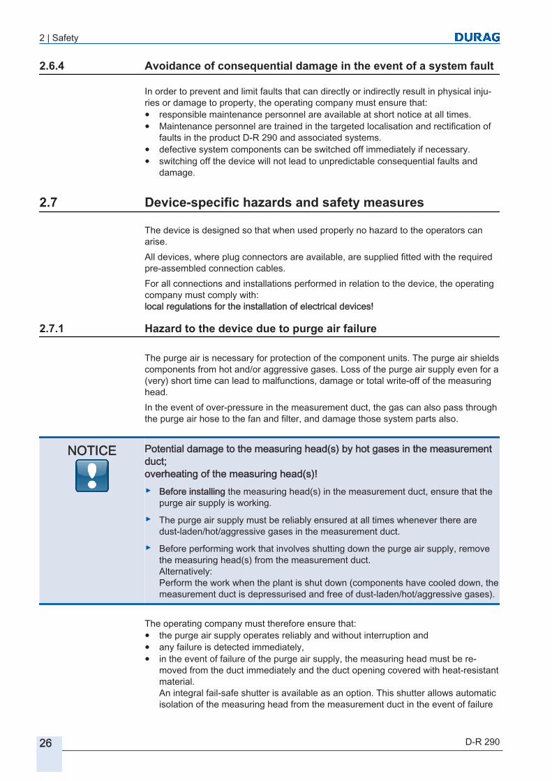
NOTICE Potential damage to the measuring head(s) by hot gases in the measurement duct;overheating of the measuring head(s)!▶ Before installing the measuring head(s) in the measurement duct, ensure that the
purge air supply is working.
▶ The purge air supply must be reliably ensured at all times whenever there are dust-laden/hot/aggressive gases in the measurement duct.
▶ Before performing work that involves shutting down the purge air supply, remove the measuring head(s) from the measurement duct. Alternatively:Perform the work when the plant is shut down (components have cooled down, the measurement duct is depressurised and free of dust-laden/hot/aggressive gases).
The operating company must therefore ensure that:● the purge air supply operates reliably and without interruption and● any failure is detected immediately,● in the event of failure of the purge air supply, the measuring head must be re
moved from the duct immediately and the duct opening covered with heat-resistant material.An integral fail-safe shutter is available as an option. This shutter allows automatic isolation of the measuring head from the measurement duct in the event of failure
2.6.4
2.7
2.7.1

2 | Safety
D-R 290 27
of the purge air supply. For a short time this reliably prevents damage to the device. The fail-safe shutter is not suitable for protecting the measuring head against overheating for an extended period!
Description and location of safety equipment and emergency stop mechanisms
The operating company must incorporate safety measures for the product Dust and Opacity Monitor D‑R 290 into the safety concept for the overall system. This also includes setting up and describing safety and emergency stop mechanisms, including giving the location of the associated emergency stop buttons.
2.8

2 | Safety
28 D-R 290

D-R 290Dust Concentration and Opacity Monitor of the
Second Generation
33 Delivery
3.1 Delivery information
3.2 Transportation, packaging and storage3.2.1 Safety instructions for transport
3.2.2 Incorrect transport
3.2.3 Transport inspection
3.2.4 Packaging
3.2.5 Storage conditions
3.3 Scope of supply3.3.1 Standard scope of supply
3.3.2 Optional equipment
3.3.3 Reflectors
3.3.4 Optional version variants

30 D-R 290

3 | Delivery
D-R 290 31
DeliveryThis section contains information about the items delivered, special accessories, approvals, warranty and application areas etc.
Delivery information
The items delivered in each case are listed on the shipping documents enclosed with the delivery in accordance with the valid sales contract. On receipt, immediately check the delivery for completeness and transport damage.
Transportation, packaging and storage
Safety instructions for transport
The products delivered generally concern an electronic device. It must be handled with the necessary care. Avoid major knocks, vibration and moisture.Where there are extreme fluctuations of temperature and moisture, condensation can cause moisture to build up within the device. This can cause an electrical short circuit.After transportation of the device, do not put it into operation until the device, including its internal parts, has acclimatised to the ambient temperature.
Incorrect transport
WARNING Risk of injury due to incorrect transport!Incorrect transport can result in serious personal injury and material damage.
▶ When unloading the packages, following delivery and internal transportation, exercise caution and observe the symbols and information on the packaging.
▶ Where necessary use appropriate lifting gear to unload the packages. The safe working load of the lifting gear must be at least the total weight of the items delivered.
▶ Only use the slinging points provided.
▶ Do not stand underneath loads when they are being lifted or set down; and keep out of the hazard area.
Transport inspection
Upon receipt, immediately check the delivery for completeness and transport damage. If any external damage in transport is evident:1. Submit a claim immediately to the carrier and to the DURAG GROUP
DURAG GROUP company addresses can be found on page DURAG GROUP company addresses
2. Grant the delivery only qualified acceptance.3. Endorse the transport documents or the carrier's delivery note with particulars of
the damage.4. Submit the claim.
Hidden transport damage must be the subject of a claim within 7 days.
3
3.1
3.2
3.2.1
3.2.2
3.2.3

3 | Delivery
32 D-R 290
NOTICESubmit a claim for every defect as soon as it is detected. Claims for damages can only be made within the contractual time limits for claims.
Packaging
The individual packages are packed according to the anticipated transportation conditions.The packaging should protect the individual components against transport damage, corrosion and other damage until they are installed. Therefore, do not destroy the packaging and only remove it shortly before installation.Where possible, use the original packaging for future transportation. The materials and any moulded parts used in the packaging are designed to ensure safe transport.
If no return agreement has been made for the packaging, separate the materials by type and size and either store them for further use or send them for recycling.
Incorrect disposal can pollute the environment!Packaging materials are valuable raw materials and, in many cases, can be reused or effectively processed and recycled.Dispose of packaging materials in an environmentally friendly manner.Observe the applicable local waste disposal regulations.(see also section 5.10.2 Disposal of the Dust Concentration and Opacity Monitor [} 104])
Storage conditions
Store the Dust and Opacity Monitor D‑R 290 and spare parts under the following conditions:● Do not store outdoors.● Store in a dry, dust-free location.● Do not expose to aggressive substances.● Avoid storage below the dew point.● Protect the Dust and Opacity Monitor against mechanical damage.● Storage temperature: -20°C to 50°C● Relative humidity: 20 % to 80 % (non-condensing)● In the case of storage for longer than 3 months, check the general condition of all
parts and the packing regularly. If required, top up or replace the anti-corrosion protection. The transport packaging is not normally suitable for long-term storage.
NOTICE If necessary for the goods, the packages may display storage instructions in addition to the requirements set out here. Note the instructions on the packages and comply with them!
3.2.4
Handling packaging materials
3.2.5

3 | Delivery
D-R 290 33
Scope of supply
The actual delivery may differ from the standard items supplied listed here for special designs, selection of additional ordering options or due to the latest technical modifications from the explanations and illustrations in this manual. The product(s) delivered is/are detailed on the delivery note.The standard scope of supply is listed without obligation in the following table, together with its features.
Standard scope of supply
Scope of supply of the typical overall D‑R 290 system: Quantity re
quired per system
Equipment
Complete measuring system D‑R 290 consisting of:1 piece D‑R 290 M measuring head:
Pitch circle diameter 100 mm
1 piece D‑R 290 R reflector:Pitch circle diameter 100 mm
1 piece e.g. D‑ISC 100
A-
0-
0-
6
for use with a sensor e.g. for D-R 290consisting of:● Control and display unit● Power supply unit 90-264V~, 200VA● 6x M20x1.5 cable glandsFor details see Technical data D-ISC 100
1 piece Blower assembly (purge air unit) D-BL, for purge air delivery quantities 40/60 m3
(for systems with 100 mm pitch circle diameter)
Purge air hose 10 m(standard)Ø 40mm, temperature range – 25 to + 80°Cwith attachment clips
3.3
3.3.1

3 | Delivery
34 D-R 290
Scope of supply of the typical overall D‑R 290 system: Quantity re
quired per system
Equipment
2 pieces D‑R 290 welded-in pipes with adjustment flangematerial 1.0037 ST37, pitch circle diameter 100 mm,hose outside Ø 65 mm, tube length 200 mm
1 piece Individual test certificate for the delivered device
Table 3.1: Typical scope of supply D‑R 290
Item no. Operating manual in4 009 351 German4 009 352 Englishx xxx xxx State the language (check availability)
Standard for deliveries outside the EC is English,unless specified otherwise!
Table 3.2: Operating manual
(Illustrations may differ from the actual appearance.)
Optional equipment
Article number
Equipment
1 piece D‑R 290 M measuring head:Pitch circle diameter 150 mm
1 piece D‑R 290 R reflector:Pitch circle diameter 150 mm
4 004 908 e.g.D-TB 100 supply unit(terminal box)for an individual sensor, incl. mains adaptor 90-264V~, 24V , 2A box with 6x cable glands M20x1.5 and 21 terminals connecting cable with 17-pin M23 socket see below
A
-0
-0
-6
-B
3.3.2

3 | Delivery
D-R 290 35
Article number
Equipment
4 004 649 Pre-assembledconnecting cable:length e.g. 3 m
CBL
-U1C
-PCG
-03
-PP3
1 119 341 D-ESI 100 SETParameterisation softwareconsisting of: Licence for one workstation, Software on USB memory stick, Special USB cable
Welded-in pipes with adjustment flanges(other standard lengths on request)
Pitch circlediameter
Hose outside Ø available tube length
Material
1 112 328* 100 mm(* = standard)
65 mm 200 mm ST 37/1.00371 107 241 316Ti/1.45711 115 002 89 mm 500 mm ST 37/1.00371 115 433 316Ti/1.45711 101 386 150 mm 240 mm ST 37/1.00371 101 390 316Ti/1.45711 122 576 114.3 mm 500 mm ST 37/1.00371 122 578 316Ti/1.45711 107 246 Protective device (automatic fail-safe shutter) D-SK 290 MA
115/230 V and 50/60 Hz(2 items recommended, one each for the measuring head and the reflector)
1 123 903 D-SK AE control device protective device (incl. supercaps)complete with housing(recommended 2 items, one each for the measuring head and the reflector)
1 109 0xx Air flow sensor protective device F3(recommended 2 items, one each for the measuring head and the reflector)various lengths of connecting cables
4 008 49x D‑R 290 CBL-U4C-PP6-xxconnecting cable for connecting the D-SK AE with the measuring head D-R 290various lengths
2 pieces Blower assembly (purge air unit) D-BL, for purge air delivery quantities 100/120 m3
(two blowers are needed for systems with 150 mm pitch circle diameter)

3 | Delivery
36 D-R 290
Article number
Equipment
1 104 170 Purge air hose extension /m
1 101 403 Laser adjusting device for installing the welded-in pipeD-R 280-70
1 108 061 Test filter (3 pieces) for testing the linearity to EPA specificationsD−R 290-85
1 108 565 Test filter (4 pieces) for testing the linearitybetween 20-80 % opacityD−R 290-86
1 107 242 Weather protection cover for the measuring head (stainless steel)D-WSH 290 M
1 107 243 Weather protection cover for the reflector (stainless steel)D−WSH 290 R
1 107 176 Weather protection cover for the purge air unit (stainless steel)D−BL WSH 460
1 107 963 Weather protection cover for the control device protective device(D−SK AE) (stainless steel) D−SK AE WSH
1 106 794 Temperature transmitter (transducer) 0..600°C D–FL 100 TM-H1 108 375 Temperature transmitter (transducer) 0…100°C or 0…400°C
D−FL 100 TM−E
Table 3.3: Optional equipment D‑R 290
(Illustrations may differ from the actual appearance.)
Reflectors
The reflector type is selected according to the length of the measuring section (distance from flange to flange). During installation please check that the length of the measuring section matches that stated when the system was ordered and for which the device has been designed. Measurement heads and reflectors that are matched to each other as a measuring unit must be installed as a pair facing each other.For the available reflectors see section 4.3.1 Possible system configurations [} 51].
3.3.3
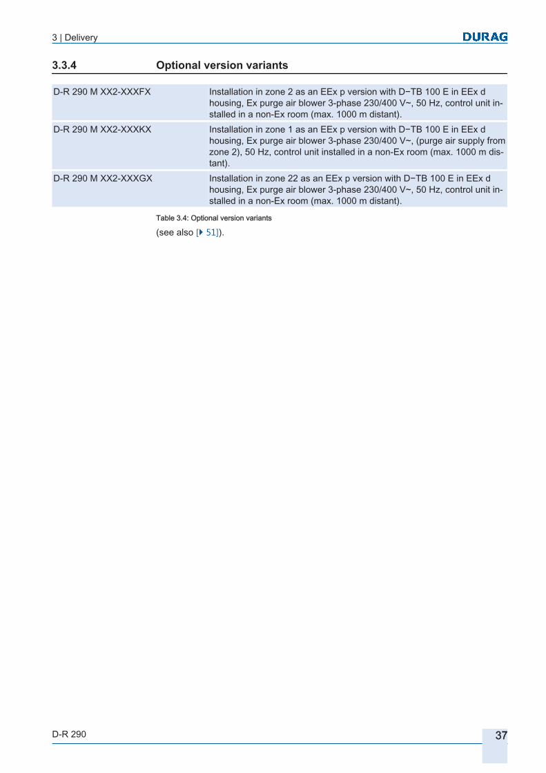
3 | Delivery
D-R 290 37
Optional version variants
D‑R 290 M XX2-XXXFX Installation in zone 2 as an EEx p version with D−TB 100 E in EEx d housing, Ex purge air blower 3-phase 230/400 V~, 50 Hz, control unit installed in a non-Ex room (max. 1000 m distant).
D‑R 290 M XX2-XXXKX Installation in zone 1 as an EEx p version with D−TB 100 E in EEx d housing, Ex purge air blower 3-phase 230/400 V~, (purge air supply from zone 2), 50 Hz, control unit installed in a non-Ex room (max. 1000 m distant).
D‑R 290 M XX2-XXXGX Installation in zone 22 as an EEx p version with D−TB 100 E in EEx d housing, Ex purge air blower 3-phase 230/400 V~, 50 Hz, control unit installed in a non-Ex room (max. 1000 m distant).
Table 3.4: Optional version variants
(see also [} 51]).
3.3.4

3 | Delivery
38 D-R 290

D-R 290Dust Concentration and Opacity Monitor of the
Second Generation
44 Product description
4.1 Fundamental features
4.2 Device and Function description4.2.1 Principle of operation
4.2.2 Measurement principle
4.2.3 Transmission
4.2.4 Opacity
4.2.5 Calculation of the opacity at the flue stack opening
4.2.6 Optical density (extinction)
4.2.7 Calculation of the dust concentration
4.3 System components4.3.1 Possible system configurations
4.4 Applications, Designated use
4.5 Conformity/approval
4.6 Designation of device components for the D-R 290
4.7 Identification of the product4.7.1 Information about the type label

40 D-R 290

4 | Product description
D-R 290 41
Product descriptionThis section explains the units that make up the measuring system and how these units work together. It lists the basic characteristics of the products and defines the designations of the device components.It also lists various alternative arrangements with other measurement heads and tube diameters / flange diameters.This Operating manual is applicable to the 2nd generation Dust Concentration and Opacity Monitors D‑R 290 . The devices are based on the DURAG sensor concept and are compatible with the D−ISC 100 universal control unit and D−ESI 100 PC software.
Fundamental features
Optical transmission meters of proven suitability and certified for measurement of the opacity of the gas being measured. Capable of being calibrated for measurement of a range of dust concentrations, from low to high.Suitable for use in plants for which the monitoring of the dust emissions is required by law.The outputs from the measuring heads and the control unit can be freely assigned to four digital channels which can parameterised independently of each other. This means that the optical density, dust content, opacity etc. can be output simultaneously.Other features are:● Continuous in situ [} 195] measurement directly in the smoke gas flow, contact-
free , without extraction of a sample.● Long working life due to the use of a semiconductor light source.● Outstanding measured value basis thanks to use of a super wide band diode
(SWBD). This broad spectrum enables a more stable measurement than can be achieved using conventional LEDs.
● Cyclical system function test; additional automatic internal contamination checks and associated measured value corrections.
● Long maintenance intervals due to the supply of a protective shield of purge air in front of the measurement head and reflector and the heated outer glass of the measuring device.
● Simple to install and operate using the external control unit with a digital display or using the operating software installed on a laptop or tablet PC via a USB connection.
● In accordance with the DURAG sensor concept, the system uses the D-ISC 100 universal operation unit for visualisation of the measured values. The D-ISC 100 permits the use of a variety of input and output interfaces (Modbus serial and TCP to VDI 4201, analogue inputs and outputs, relay contact inputs and outputs.)
Device and Function description
In the standard system, the D−R 290 Dust Concentration and Opacity Monitor consists of five main components:● measuring head D‑R 290 M● reflector D‑R 290 R● D-TB 100 supply unit and / or● D-ISC 100 control unit● D-BL blower assembly (purge air unit)● Two welded-in pipes with adjustment flange D‑R 290 E or D‑R 290 − 150 E.
4
4.1
4.2

4 | Product description
42 D-R 290
The housing is constructed of high-quality materials such as painted aluminium die-castings and stainless steel (1.4301 or 1.4571).All five units complement each other within the dust concentration and opacity monitoring system in the twin-beam alternating light process [} 196] using the auto-collimation principle [} 195] . This is designed to monitor plants where quantitative [} 196] measurements of dust concentrations are required.
Opticalmeasuring unit Reflector
Welded-in pipeswith
adjustment flange
Purge airunit Universal operation unit
(display and control unit)
Fig. 4.1: System components● Protective device (not shown) consisting of:
○ Fail-safe shutter○ Control electronics○ Air flow sensor○ Connecting cable
Principle of operation
The Dust Concentration and Opacity Monitor D‑R 290 operates on the transmission principle [} 196]. The measuring head (receiver) and reflector are mounted opposite each other. Through the use of the auto-collimation principle [} 195] the measuring light traverses the measurement path twice and the sensitivity of the measurement is doubled (see Fig. 4.2 ).The modulated measuring light transmitted from the measuring head initially traverses the measuring path as far as the reflector. This reflects it back so that it passes through the measuring path a second time. The attenuation of the measurement light beam by the dust particles is thereby proportional to the particle density. The homogeneous spot of light on the reflector side has a substantially larger diameter than the
Optional:
4.2.1

4 | Product description
D-R 290 43
reflector surface area. This simplifies adjustment and avoids measurement errors in the event of thermal distortion of the surfaces on which the measuring head and reflector are mounted.
MeasurementComparison standard
Measuring section
Reflector
Zero pointreflectorTransmitter
Turntable plate
50% splitter mirror
Receiver
Fig. 4.2: Measurement
The inevitable intensity drift of the optical sensor (receiver) and the semiconductor light source caused by ageing and temperature influences are compensated automatically by the device. For this purpose the modulated light from the super wide band diode is divided into a measuring light beam and a comparison light beam (see Fig. 4.4 ). An optical receiver receives the measurement and comparative measurement beams alternately. The changeover between measuring light and comparison light is achieved by a stepper motor which rotates the turntable plate (see Fig. 4.3 ) so that the light path to the reflector is blocked whilst the optical path to the comparison standard is open. The difference between the two measurements represents the actual effect of the ageing (of the lamp) and influence of the temperature.
Comparison measurementComparison standard
Measuring section
Reflector
Zero pointreflectorTransmitter
Turntable plate
50% splitter mirror
Receiver
Fig. 4.4: Comparison measurement
The comparison light beam passes through the integrated comparison path every 2 minutes for approx. 5 seconds. The value of the comparison light is digitised and saved for the following measurement light period.
Fig. 4.3: Turntable plate

4 | Product description
44 D-R 290
Zero point measurementComparison standard
Measuring section
Reflector
Zero pointreflectorTransmitter
Turntable plate
50% splitter mirror
Receiver
Fig. 4.5: Zero point measurement
To check the correct operation of the D‑R 290 a checking cycle is performed at a periodic interval configurable from 0 to 720 hours (0 = no control cycle). During this cyclical check a zero point reflector is used to automatically check the contamination control of the optical surfaces. The zero point and a reference are also measured automatically.During the reference point measurement (Fig. 4.6 ) a mesh filter (see Fig. 4.3 ) with a defined light attenuation is moved into the measurement beam. A check is then made that the measured attenuation corresponds with the defined value. For zero point measurement (Fig. 4.5 ) the measurement beam is reflected directly in front of the measurement medium. It thus passes through all the lenses and relevant optical components, just as in the real measurement procedure.The measurement results for subsequent measurements are corrected to compensate for the measured difference in value (contamination). If the contamination exceeds a certain percentage (configurable between 0 and 10%), a warning is indicated. If the contamination exceeds a higher percentage (>10%), an error message is indicated, and the measured values from the device are thereafter no longer valid.The evaluation electronics determines the transmission from the received measurement light and the intensity of the comparison light. From this the opacity [} 195], or alternatively the extinction [} 195] is measured. The extinction can be calibrated and can be specified as dust concentration in mg/m³.Furthermore for a known measuring path length the extinction coefficient and the Koschmieder visual range can be calculated.All the calculated values can be freely assigned to the four digitial measuring channels.
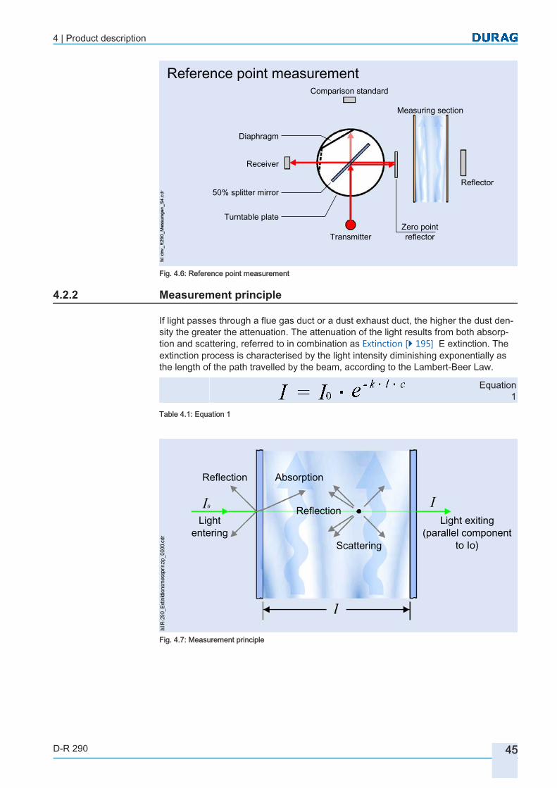
4 | Product description
D-R 290 45
Reference point measurementComparison standard
Measuring section
Reflector
Zero pointreflectorTransmitter
Turntable plate
50% splitter mirror
Receiver
Diaphragm
Fig. 4.6: Reference point measurement
Measurement principle
If light passes through a flue gas duct or a dust exhaust duct, the higher the dust density the greater the attenuation. The attenuation of the light results from both absorption and scattering, referred to in combination as Extinction [} 195] E extinction. The extinction process is characterised by the light intensity diminishing exponentially as the length of the path travelled by the beam, according to the Lambert-Beer Law.
Equation 1
Table 4.1: Equation 1
Reflection Absorption
Scattering
ReflectionLight
enteringLight exiting
(parallel componentto Io)
Fig. 4.7: Measurement principle
4.2.2
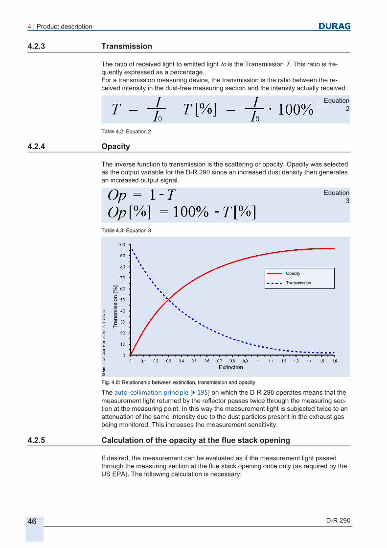
4 | Product description
46 D-R 290
Transmission
The ratio of received light to emitted light Io is the Transmission T. This ratio is frequently expressed as a percentage.For a transmission measuring device, the transmission is the ratio between the received intensity in the dust-free measuring section and the intensity actually received.
Equation 2
Table 4.2: Equation 2
Opacity
The inverse function to transmission is the scattering or opacity. Opacity was selected as the output variable for the D‑R 290 since an increased dust density then generates an increased output signal.
Equation 3
Table 4.3: Equation 3
Tran
smis
sion
[%]
Extinction
Opacity
Transmission
Fig. 4.8: Relationship between extinction, transmission and opacity
The auto-collimation principle [} 195] on which the D‑R 290 operates means that the measurement light returned by the reflector passes twice through the measuring section at the measuring point. In this way the measurement light is subjected twice to an attenuation of the same intensity due to the dust particles present in the exhaust gas being monitored. This increases the measurement sensitivity.
Calculation of the opacity at the flue stack opening
If desired, the measurement can be evaluated as if the measurement light passed through the measuring section at the flue stack opening once only (as required by the US EPA). The following calculation is necessary:
4.2.3
4.2.4
4.2.5

4 | Product description
D-R 290 47
Op Opacity at the measuring point (value corresponding to a single passage)
Op1 (measured) opacity at the measuring point(value corresponding to a double passage; auto-collimation principle [} 195] )
Op2 Opacity at the flue stack opening(value corresponding to a single passage)
L1 Diameter of the flue stack at the measuring pointL2 Diameter at the flue stack openingPLCF Path length correction factor (flue stack correction factor)
Table 4.4: Legends in the formulae
Table 4.5: Flue stack correction factor
Equation 4
Table 4.6: Equation 4
Based on the (measured) double attenuation of the measurement light at the measuring point, we have the following relationship:
Equation 5
Table 4.7: Equation 5
Flue stack mouth
Measuring point
Fig. 4.9: Reference points for determination of the opacity

4 | Product description
48 D-R 290
If necessary the evaluation system of the D−R 290 can perform these calculations, convert the measurements accordingly and output the results.To do this, the flue stack correction factor (L2 / L1) should be set in the evaluation unit . The setting is performed as described on page 118. The flue stack correction factor setting affects the measured values in the type code "general opacity".
Measuring point = 6.00 m = L1 Flue stack mouth = 5.10 m = L2 Flue stackcorrection factor
= L2/L1 = 5.10 m/6.00 m = 0.850
The standard setting for the flue stack correction factor is 1. The effect of this setting is that the opacity is displayed as if the measurement light passed through the measuring section at the measuring point only once. If the calculation should not be performed by the D−R 290, enter the factor 2.
Optical density (extinction)
The logarithm of the inverse of the transmission is designated the optical density OD or also as the extinction.
Equation 6
Table 4.8: Equation 6
Equation 1
Table 4.9: Equation 1
Calculation of the dust concentration
The measurement of the dust concentration is performed at constant emitted light intensity I0 and a fixed value l for the measuring section. The extinction coefficient k depends on a number of parameters (such as size of the dust particles or the material of the dust particles, characterised by specific gravity, refraction index and absorption constant for the light wavelength used) and can be different for every plant. In addition, in combustion plants as well as dust creating plants e.g. the cement industry, the size of the dust particles varies as the loading of the plant changes. Also an important influencing factor is the mode of action of wet dust extractors (water vapour and condensation cores) and the respective filter performance. Due to the number of influencing variables, there is no simple formula that can be given for the relationship between the dust loading and the transmission. Therefore the relationship between the device display in optical density and the dust emission must be determined for every plant by means of gravimetric measurement (gravimetry [} 195]).Using lnT = ln10 ⋅ lgT, Equation 1 can be reformulated as:
Example:
4.2.6
4.2.7

4 | Product description
D-R 290 49
Equation 7
Table 4.10: Equation 7
The dust concentration c is:
Equation 8
Table 4.11: Equation 8
I0 emitted light k extinction coefficientI received light OD Optical densityl Measurement path length, (x 2 for
auto-collimation)c Dust concentration
b Dust coefficient a Dust offset
For the reasons already mentioned, the coefficients a and b must be determined by gravimetric measurement. The measurements to be performed must be performed with the occurring plant loads and the difference filtering possibilities of the respective plant. Check measurements for different types of fuel are necessary. Only when these comparisons figures are available can the extinction values be correctly evaluated regarding the dust emission. Since the dust concentration is subject to statistical fluctuations, statistical methods are best for determining the calibration curve for the relationship between extinction [} 195] and dust concentration.For further information please refer to the standards VDI 3950 (Germany), EN 14181, EN 13284-1, EN 15259 and others.The setting of the coefficients in the device is described in section 7.7.6 Settings [} 142].

4 | Product description
50 D-R 290
System components
Standard OptionalA Measuring head C Fail-safe shutterB Volumetric flow sensor F Weather protection coverD Reflector G Temperature transmitter (for stand
ardisation)E Welded-in pipe with adjustment
flangeJ Electronics for fail-safe shutter
H Purge air unit K D-ISC 100 control unit
Connections1 Operating power supply 4 Control cable for the fail-safe shut
ter2 Measurement cable for the volu
metric flow sensor5 Measuring head connection
4.3

4 | Product description
D-R 290 51
3 Connection for the fail-safe shutter 6 Various connections (Modbus TCP/RTU, analogue and digital connections)
Fig. 4.10: System components
Possible system configurations
Various components are available for the different measuring sector lengths from 1 to 18 m. These differ in their designs and in reflector material that is used.The following designs are available:● D‑R 290 M XX2-10XXX pitch circle diameter Ø 100 mm● D‑R 290 M XX2-15XXX pitch circle diameter Ø 150 mm for longer measuring sec
tion lengths
Measuring head Reflector Reflector type Measuring path Pitch circle diameter Ø
D‑R 290 M XX2-10XXX D‑R 290 R 1XX-10X
Scotchlite
1 m to 2.25 m
100 mm
D‑R 290 M XX2-15XXX
D‑R 290 R 1XX-15X150 mm
D‑R 290 M XX2-10XXX D‑R 290 R 2XX-10X
Triple with lenses
1.75 m to approx. 8 m
100 mm
D‑R 290 M XX2-15XXX
D‑R 290 R 2XX-15X
1.75 m to approx.
18 m
150 mm
Table 4.12: Standard systems D−R 290
Various different tube diameters are available to suit the different adjustment flange diameters.This table shows the maximum tube lengths up to which measurement can be performed. The welded-in pipes should also project about 30 mm into the measurement duct. The specifications are in relation to the standard welded-in pipes with adjustment flange (1.0037). Special lengths are available on request.
4.3.1
Design

4 | Product description
52 D-R 290
Fig. 4.11: Dimensional diagram D−R 290 standard welded-in pipe with adjustment flange (↘= red dot)
D1 Pitch circle diameter Ø
[mm]
D2 Tube outside Ø
[mm]
D3 Tube inside Ø
[mm]
D4 Flangeoutside Ø
[mm]
L1 max. permissible
length[mm]
L2 Stud length[mm]
100 65 59 130 200 ~73100 89 83 130 600 ~73150 89 83 190 600 ~80150 114.3 107.1 190 1000 ~80
Table 4.13: Welded-in pipe lengths
The following reflectors can be used for the D‑R 290 measuring system :
Suitable for measuring path Type Version 1 m to 2.25 m
D‑R 290 R 1XX-10X
Scotchlite
D‑R 290 R 1XX-15X
1.75 m to approx. 8 m D‑R 290 R 2XX-10X
Triple with lenses
1.75 m to 18 m D‑R 290 R 2XX-15X
Table 4.14: Reflectors
Reflectors

4 | Product description
D-R 290 53
If the power supply or the purge air fails, the fail-safe shutter of the protective device will be closed. The control electronics monitors the air flow sensor in order to detect a failure of the purge air. Integrated maintenance-free supercaps supply the necessary power to the shutters to close them within approx. 2 seconds. After the failure has been rectified the fail-safe shutter automatically opens again. A message is output giving the current status of the shutter. For dimensions see 9.3.5 Dimensional diagram fail-safe shutter D-SK MA [} 187] The control electronics D−SK AE are contained in a compact aluminium housing (colour: Traffic blue RAL 5017) with a transparent cover. The front panel is protected by the transparent cover which can be swung away to the left. The connection terminals are contained in a separate area within the housing (behind a swing-away cover in the lower part of the housing). The housing is protected against sprayed water to protection type IP 65. For the diameter of the attachment holes and attachment dimensions see 9.3.4 Dimensional diagram of the control electronics D-SK AE [} 186].
Applications, Designated use
The Dust and Opacity Monitor is a device for monitoring dust emissions in e.g.:● of flue gas, air or process gas● in ducts, pipes or flues● on ventilation units generally● on incineration plants generally● on waste, special waste and sewage sludge incineration plants,● on cement manufacturing plants● on power stations with gas, oil, coal or mixed fuel firing● on plants for incineration of biomass● Refineries and other petrochemical plants● Soot factories, conversion plants, asphalt mixing plants, dust filter plants, …The Dust Concentration and Opacity Monitor D‑R 290 satisfies the official emission monitoring for medium to high concentrations (according to the European specifications and the EPA [} 195]).
WARNING Danger when using other than for the intended application!Any use other than or beyond the designated use of the of the Dust and Opacity Monitor can lead to hazardous situations.There is a risk of personal injury and material damage.Only ever operate the Dust and Opacity Monitor in compliance with the parameters stated on the type label and to the parameters listed in the 9.2 D-R 290 technical data [} 179]. All specifications in this operating manual must be strictly complied with!
Claims of any kind resulting from incorrect use will not be accepted.The operating company bears sole liability for all damage caused by use other than in accordance with the designated use.
The D‑R 290 is a class A product. If used in residential areas devices of this kind of class can cause radio interferences. In this case the operating company is responsible to take appropriate measures.
Protective device
Control electronics housing
4.4

4 | Product description
54 D-R 290
Fault-free and safe operation of this of the Dust and Opacity Monitor depends on appropriate transport, correct storage, installation and assembly, as well as careful operation and maintenance by qualified personnel.Observe and comply with the parameters listed in the 9.2 D-R 290 technical data [} 179].
Conformity/approval
The D‑R 290 has been developed, manufactured, tested and documented in conformity with the applicable safety standards.Therefore under normal circumstances no hazards arise from this device either for the health of personnel or for damage to equipment. To minimise hazards, compliance with the handling regulations and safety instructions in this manual is essential. Comply with these instructions for configuration, installation, designated use and maintenance.Further information on the standards and directives that have been applied can be found in section --- FEHLENDER LINK ---.
Designation of device components for the D-R 290
1
Carrying handle
2 Mini-USB connection(with cover)
3 Housing cover
4 Window for the status LEDs
5 Quick-release fastener
6 Device flange(purge air flange)
7 Purge air connection
4.5
4.6

4 | Product description
D-R 290 55
8 Optional connectionfor a temperature sensor
9 Device connection
10 Purge air sensor connectionand fail-safe shutter(measuring head)
11 Purge air sensor connectionand fail-safe shutter(reflector)
12 Viewing window fordevice alignment(sighting mechanism)
13 Measuring window
14 Zero point reflector(in the measuring position)
15 Filter adapter (without filter)
16 Zero point reflector(in the reference position)
Table 4.15: Designation of device components: Measuring head and reflector

4 | Product description
56 D-R 290
1 Circuit diagram2 Connection terminals3 Spring clip for
cable screen4 Cable gland5 Lower part of the housing
with attachment plates as necessary (not shown)
Table 4.16: Designation of device components: Supply unit
1 Stainless steel baseplate2 Filter housing3 Filter adapter4 Filter lower part with air inlet5 Filter spring clip6 Blower motor7 Cable gland
for connection cable8 Junction box
Table 4.17: Designation of device components: Purge air unit
The designation of the device components of the optional D−ISC 100 universal operation unit is described in the operating manual supplied with that unit.

4 | Product description
D-R 290 57
Identification of the product
The type label is located:on the measuring head on the device side
on the reflector on the device side
on the supply uniton the device side
on the blower assembly (purge air unit)on the baseplate
4.7
Standard:

4 | Product description
58 D-R 290
on the fail-safe shutterD‑SK 290 MAon the shutter bracket alongside the motor
on the control electronicsD‑SK AEon the device cover
on the control unitD−ISC 100on the device side
Table 4.18: Where do I find the type label?
Option:

4 | Product description
D-R 290 59
Information about the type label
The information on the type label has the following meaning:
Fig. 4.12: type label
1 DURAG Manufacturer2 www.durag.de Manufacturer's address, homepage3 D-R 290 Device type designation4 M Module (here e.g.: measuring head)
EC2 variant; (here e.g.: emission measurement to EN 15267 (ext. certificate), EU, generation 2
-10SAE Special device fittings (here e.g.: Process connection 40 mm; LK D=100 mm, air inlet D=40 mm, purge flange with swirl generator; tested for suitability; protection type IP 65, for installation in the N-EX zone; interface M23 connection for sensor, USB, SSK M, SSK R)
5 PN: Order number6 SN: Serial number7 U: 24VDC ( ) 48VA Operating voltage8 IP65 Protection type9 Before starting any work, read the operating manual!
10 Declaration of conformity and type approval supplied
11 Date Date (year) of manufactureThe coloured backgrounds in the illustration of the type label are to assist in making clear the information areas in this description; the colours are not shown on the physical type labels!
Table 4.19: Example of a type label D‑R 290
4.7.1

4 | Product description
60 D-R 290

D-R 290Dust Concentration and Opacity Monitor of the
Second Generation
55 Installation
5.1 Safety5.1.1 Transport to the place of installation
5.1.2 Skill levels of personnel for installation and commissioning
5.2 Preparation for installation5.2.1 Preconditions for operation
5.2.2 Instructions for planning the electrical connections to the system
5.2.3 Instructions for selection the device variant and measuring point
5.2.4 Free space around the device housing
5.3 System installation sequence :
5.4 Installation of the D−R 290 measuring head and reflector 5.4.1 Standard installation of the welded-in pipes with adjustment flanges
5.4.2 Installation variants
5.4.3 Alignment of the tube stubs
5.4.4 Installation of the measuring head and reflector
5.4.5 Electrical connections to the measuring head
5.4.6 Meaning of the LEDs
5.4.7 Configuration of the relay outputs
5.5 Installation of the D-SK 290 protective device 5.5.1 Installation sequence for the measuring head and reflector (when the D-SK 290 protective
device is used)
5.5.2 Display LEDs of the control electronics
5.5.3 Installation protective device D-SK 290

62 D-R 290
5.5.4 D-SK AE electrical connection
5.5.5 Configuring the protective device
5.5.6 Checking the protective device
5.5.7 Commissioning the D-SK AE
5.6 Installation of the D-ISC 100 control unit5.6.1 Connecting the supply and control unit
5.7 Installation of the supply unit5.7.1 Installation of the D-TB 100 supply unit
5.7.2 Electrical connection to the D-TB 100 supply unit
5.8 Installation of the purge air unit5.8.1 Selection of an installation location of the purge air unit (blower)
5.8.2 Arrangement and installation of the purge air unit
5.8.3 Electrical installation of the purge air unit
5.8.4 Electrical connection for the purge air motor
5.9 Active operation
5.10 Dismantling and disposal5.10.1 Dismantling
5.10.2 Disposal of the Dust Concentration and Opacity Monitor
5.10.3 RoHS compliance

5 | Installation
D-R 290 63
Installation
Safety
DANGER High voltage. Risk of fatal injury due to electric shock!Touching live parts poses an immediate risk of fatal injury. Damage to the insulation or to individual components can lead to fatal injury.
▶ If there is any damage to the insulation, switch off the power supply immediately and have it repaired.
▶ Permit only qualified electricians to work on electrical equipment.
▶ Before opening the casing of a device or removing a guard protecting against touching it, deenergise the device, test it to ensure it is electrically dead and secure it against switching on again.
▶ Keep moisture away from live components. This can lead to short circuits.
Wherever possible, install or remove components only when the plant is shut down. Before opening the duct access ports:● Make sure that no overpressure is present in the measurement duct.● Make sure that no toxic gases are present in the measurement duct.If it is not possible to shut down the plant, and toxic gases, which may be at high temperature or pressure, are present in the measurement duct:
WARNING Health hazard due to hot and/or toxic gases in the duct!When a duct access port (such as a welded-in tube) is opened, pressurised gases may escape.
▶ Always wear suitable protective equipment (such as a face mask, heat-resistant gloves and clothing, protective breathing equipment).
▶ The applicable specifications safety regulations and the operating company working instructions for the plant must be complied with.
CAUTION Material damage due to unauthorised personnelIncorrect handling of the equipment can lead to serious material damage.
▶ Permit only appropriately skilled and trained personnel to work on the D‑R 290 .
5
5.1
5 | Installation
64 D-R 290
NOTICE Damage to electronic components due to electrostatic discharge (ESD)Electronic components are becoming smaller and smaller and more and more complex. Their susceptibility to damage from electrostatic discharge is increased accordingly. Therefore:
▶ To protect the components, measures must be undertaken to prevent electrostatic discharge during all work performed at the open device (ESD protection).
▶ To prevent static charges building up on the human body, service employees can for example be equipped with a personal earthing system.
Transport to the place of installation
Avoid heavy impacts. Wherever possible, use the original packaging for transportation. The original packaging ensures safe transport.Where there are extreme fluctuations of temperature and moisture, condensation can cause moisture to build up within the device. This can cause an electrical short circuit.After transportation of the device, do not put it into operation until the device, including its internal parts, has acclimatised to the ambient temperature.
Skill levels of personnel for installation and commissioning
Installation and commissioning of the of the Dust and Opacity Monitor must be carried out by skilled personnel (see section 2.4.1 Personnel, skills [} 22]):● Specialist staff, and for electrical work electricians with special knowledge of the
supply unit.● Service technicians can be involved for support as necessary.The operating company must provide employees with training in the following areas:● operational hazards and how to prevent them● applicable regulations relating to the assigned work● tasks assigned and possible hazards due to incorrect behaviour.
Preparation for installation
The standard system consists of:● a D‑R 290 measuring head and the associated reflector● a D−BL purge air blower● optional: a second blower (D-BL …; e.g. for units with pitch circle diameter Ø
150 mm), see Fig. 5.1 D● optional (not shown): two D−SK 290 fail-safe shutters one each for the measuring
head and the reflector● a D−ISC 100 universal control and display unit, see Fig. 5.1 A, B, D, E● optional: a supply unit (terminal box D-TB …) for power supply to the measuring
head and as a data interface, see Fig. 5.1 B, C, E● optional (not shown): a weather protection cover (as required for the measuring
head, reflector and blower)Examples for the various system configurations can be found in Fig. 5.1 .
5.1.1
5.1.2
5.2
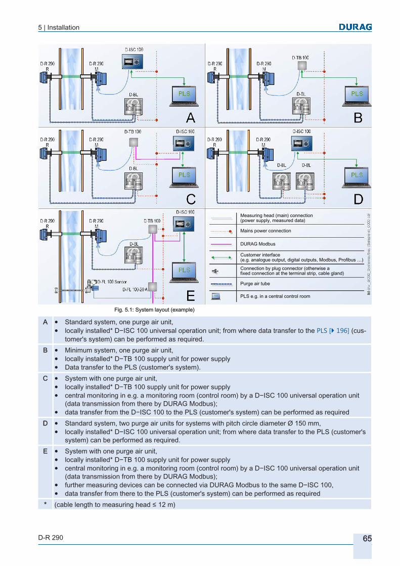
5 | Installation
D-R 290 65
Measuring head (main) connection(power supply, measured data)
Mains power connection
DURAG Modbus
Customer interface(e.g. analogue output, digital outputs, Modbus, Profibus …)
Connection by plug connector (otherwise afixed connection at the terminal strip, cable gland)
Purge air tube
PLS e.g. in a central control room
Fig. 5.1: System layout (example)
A ● Standard system, one purge air unit,● locally installed* D−ISC 100 universal operation unit; from where data transfer to the PLS [} 196] (cus
tomer's system) can be performed as required.B ● Minimum system, one purge air unit,
● locally installed* D−TB 100 supply unit for power supply● Data transfer to the PLS (customer's system).
C ● System with one purge air unit,● locally installed* D−TB 100 supply unit for power supply● central monitoring in e.g. a monitoring room (control room) by a D−ISC 100 universal operation unit
(data transmission from there by DURAG Modbus);● data transfer from the D−ISC 100 to the PLS (customer's system) can be performed as required
D ● Standard system, two purge air units for systems with pitch circle diameter Ø 150 mm,● locally installed* D−ISC 100 universal operation unit; from where data transfer to the PLS (customer's
system) can be performed as required.E ● System with one purge air unit,
● locally installed* D−TB 100 supply unit for power supply● central monitoring in e.g. a monitoring room (control room) by a D−ISC 100 universal operation unit
(data transmission from there by DURAG Modbus);● further measuring devices can be connected via DURAG Modbus to the same D−ISC 100,● data transfer from there to the PLS (customer's system) can be performed as required
* (cable length to measuring head ≤ 12 m)

5 | Installation
66 D-R 290
Preconditions for operation
Check that the following preconditions for operation of the D−R 290 Dust Concentration and Opacity Monitor are satisfied:(Based on the following checklist, the suitability of the device can quickly and easily be determined).
Checklist: Requirements for operating the D−R 290
Are the flue gas temperatures above dewpoint, so that the gas does not dissolve in condensate within the duct?
If the gas temperature regularly falls below dewpoint, the D−R 290 is unsuitable for this application.
❑
Does the measuring point lie in an explosion hazard area, or is it intended to measure explosive gas mixtures?
Only the appropriate optional version of the D−R 290 system is suitable for this application.
❑
How large is the measurement distance at the measurement location?
Refer to the table on page 52 and select the appropriate system.
❑
What measurement range is required? For this, determine the dust concentration to be expected, as well as the limit value (if any) that should be monitored.
❑
What is the wall thickness of the duct at the measuring point?
Refer to the table on page 52 and select the appropriate system.
❑
What is the gauge pressure in the measurement duct?
The maximum gauge pressure for the application of the standard blower is approximately 20 hPa.
❑
Is suitable purge air available? The fresh air sucked in by the blower for the purge air must be free of dust and oil and have a temperature of -20 to +40 °C.
❑
Is the measurement location outdoors? In this case a weather protection cover should be fitted to protect the components that are located outdoors (see page 35 ff).
❑
Is the planned installation location safe for service personnel?
The working platform should be approximately 1.5 m below the measurement opening. All parts of the measuring system must be accessible without danger. Observe the valid country-specific regulations on accident prevention.
❑
Is there sufficient space available to carry out maintenance work on the components?
Virtually all system components require the cover to be swung open for access, and sufficient space must be provided for this at the hinge side (see Fig. 5.3 and 9.3.4 Dimensional diagram of the control electronics D-SK AE [} 186]).
❑
Table 5.1: Preconditions for operation
Instructions for planning the electrical connections to the system
The electrical connection of the measuring system depends on the composition of the system● in the universal operation unit D‑ISC 100 (see also the applicable operating man
ual) or
5.2.1
5.2.2

5 | Installation
D-R 290 67
● in the terminal compartment of the D−TB 100 supply unit via a terminal strip in accordance with the connection diagram (see Fig. 5.35 ). The respective connection diagram can also be found within the supply unit.
The cables for the mains and data cables should be routed separately. The mains supply cable should use H 07 RR – U 3 G 1.5 or the equivalent. The material of the conductors and sheath must be appropriate to the conditions at the operating site. To protect the supply conductor, a 16 A automatic circuit breaker should be installed as near to the measuring system as possible. Label the MCB so that it can be identified as the isolation switch for the device. The individual conductors of the mains power supply cable must be mutually secured (e.g. using cable ties) in such a way that they cannot touch neighbouring terminals whilst being disconnected.(see also the technical data 9.2.5 D-TB 100 supply unit (terminal box) [} 181]).
Even when the plant is switched off there remains the danger of the measuring head and reflector overheating.Note that:▶ The purge air supply must continue to operate even when the plant (for which the
dust emissions are to be measured) is switched off!
▶ The purge air supply must remain switched on at all times as long as the measuring head and reflector are installed at the measuring point and exposed to the hot gas to be measured.
▶ Fail-safe shutter (optional) if installed offer only short-term protection.
The cabling between the supply unit and the customer interface (PLS [} 196]) in the control room must be carried out with screened data cables; e.g. LiHCH (TP) 8 x 2 x 0.5 mm², with twisted pairs of fine-wire flexible cores, operational capacitance approx. 80 nF/km.Connect one end of the screen in the supply unit.
Instructions for selection the device variant and measuring point
The technical requirements posed by various types of boilers or dust extraction plants, stacks flue gas flues are very varied. The wall thickness and flue stack diameter can affect the choice of system variants. Refer to the sections 4.3.1 Possible system configurations [} 51] and Fig. 5.1 .As a general principle it is recommended that the location of the measuring point is performed by the responsible measuring institute (e.g. TÜV). In addition, consideration must also be given to the intended measuring point:● feasibility of installation of the reflector● feasibility of installation of the purge air unit(s)● if necessary, feasibility of installation of the fail-safe shutter● clearance to swing out the measuring head and reflector.● if installed outdoors, the space required for weather protection covers for the
measuring system and purge air unit(s).● A duct that runs vertically is preferable to one that runs horizontally.
5.2.3

5 | Installation
68 D-R 290
Within the measurement duct…
▶ …the distribution of the dust and smoke within the gas should be as homogeneous as possible
▶ …the dewpoint of the flue gases should not be undershot
▶ ...the path of the light beam through the gas to be measured should be as nearly horizontal as possible.
The measuring point should not be just before or just after bends in the duct or changes in its cross-section. The upstream section (duct section leading up to the measuring point) should be at least 5 × D (D = internal diameter of the duct) and the downstream section (duct section leading away from the measuring point)) should be at least 2 × D (see Fig. 5.2 a). If no such location is available, the upstream section (A) should be longer than the downstream section (see Fig. 5.2 b).On flues with round internal cross-sections, "D" means the internal diameter. In the case of square or rectangular cross-sections, the hydraulic diameter is used:
Equation 10
F AreaU Scope
Table 5.2: Equation 10
The installation location should be as free from vibrations and oscillations as possible. If this is not possible, it is recommended that the installation it keep away from draughts that might induce vibration, so that the measuring system is not subject to stresses.
Fig. 5.2: Measuring point
If a measuring point is sought between a filter and an induced draught, then the installation point should be placed more towards the induced draught and less towards the filter.

5 | Installation
D-R 290 69
The measurement location must not only be accessible without hazard for commissioning and calibration work, but also for subsequent maintenance and service activities.To determine the space required, refer to Fig. 5.3 :
1 Adjustment flanges aligned to each other within ± 1°2 Duct wall 3 Welded-in pipe with adjustment
flange4 Red dot 6 Rubber sleeve7 12 disc springs * 8 1 spherical washer *9 1 self-locking nut * 10a Measuring head (MK)
10b Reflector (R) * per threaded studFig. 5.3: Installation example on a horizontal duct
Free space around the device housing
If several housings (e.g. for a universal operation unit and control electronics for fail-safe shutters) are installed alongside each other, allow sufficient clearance between them to allow the hinged parts of the housings to be swung out, according to their height. The opening screws (for the control electronics of fail-safe shutters, on the right hand side wall) must also be accessible. Otherwise it will not be possible to install the housings subsequently.For this also see the section of dimensional diagrams:
9.3.4 Dimensional diagram of the control electronics D-SK AE [} 186]
System installation sequence :
1. Check the preconditions for operation (5.2.1 Preconditions for operation [} 66])2. Select the optional system components (5.2.3 Instructions for selection the device
variant and measuring point [} 67])3. Select the measuring point (5.2.3 Instructions for selection the device variant and
measuring point [} 67])4. Plan the installation locations for purge air shutter unit(s) (5.8.1 Selection of an in
stallation location of the purge air unit (blower) [} 101])5. Install and align the welded-in pipes with adjustment flange for the measurement
and reflector units (5.4.1 Standard installation of the welded-in pipes with adjustment flanges [} 70] ff., 5.4.3 Alignment of the tube stubs [} 76])
5.2.4
5.3

5 | Installation
70 D-R 290
6. Lay the connecting cables (5.2.2 Instructions for planning the electrical connections to the system [} 66])
7. Install and connect the supply unit(s) (5.7 Installation of the supply unit [} 97] ff.)8. Install and connect the purge air unit, and test it for correct operation (5.8 Installa
tion of the purge air unit [} 101] ff.)9. Connect purge air hose pipes to the measurement and reflector units, bring the
purge air unit into operation and only then:10. Attach the measuring head and reflector to the measurement duct (5.4.4 Installa
tion of the measuring head and reflector [} 76] and 5.5.1 Installation sequence for the measuring head and reflector (when the D-SK 290 protective device is used) [} 84])
11. Make the electrical connections to the components (5.4.5 Electrical connections to the measuring head [} 79], 5.5.4 D-SK AE electrical connection [} 88], 5.7.2 Electrical connection to the D-TB 100 supply unit [} 98], 5.8.3 Electrical installation of the purge air unit [} 102] and 5.8.4 Electrical connection for the purge air motor [} 102])
12. Perform optical adjustment of the measurement unit (6.1 Optical alignment [} 107])
13. Commission the D‑R 290 and perform a function test (6 Commissioning [} 107])14. Program the necessary measurement parameters and calibrate the units;
perform a function test (6.2 Parameterisation and operation of the measuring head [} 108] ff.)
Installation of the D−R 290 measuring head and reflector
Adjustment flanges with welded−in pipe connections are provided as standard for installation of the measuring head and reflector within steel ducts. Thick installation to ducts and brickwork stacks or high exhaust gas temperatures require suitably modified flanges, which are either manufactured on site or which can be designed by DURAG. If the welded-in pipes are more than a certain length, a larger tube diameter must be selected (see Table 4.13 ).
Standard version of adjustment flanges: Steel 37 Material No. 1.0037Special optional version: V4A Material No. 1.4571
Standard installation of the welded-in pipes with adjustment flanges
Wherever possible, install or remove components only when the plant is shut down. Before opening the duct access ports:● Make sure that no overpressure is present in the measurement duct.● Make sure that no toxic gases are present in the measurement duct.If it is not possible to shut down the plant, and toxic gases, which may be at high temperature or pressure, are present in the measurement duct:
5.4
5.4.1

5 | Installation
D-R 290 71
WARNING Health hazard due to hot and/or toxic gases in the duct!When a duct access port (such as a welded-in tube) is opened, pressurised gases may escape.
▶ Always wear suitable protective equipment (such as a face mask, heat-resistant gloves and clothing, protective breathing equipment).
▶ The applicable specifications safety regulations and the operating company working instructions for the plant must be complied with.
Possible material damage when making the opening in the duct.Parts that fall may damage the duct wall or its coating.Do not allow parts that are cut out to fall into the duct.
1. First mark the installation locations for the welded-in pipes with adjustment flanges,2. Create an opening, using a technique appropriate to the material and situation of
the measurement duct.3. The tube ends should project approx. 30 mm into the inside of the duct.
During installation note:
Important comments:▶ The red dot on the adjustment flange must always be at the top when installed!
▶ The two threaded studs (A and B see Fig on the left) should be on the same horizontal level.
▶ Before the welded-in pipes with adjustment flange can finally be fixed to the duct, the tube for the measuring head and tube for the reflector must be aligned to each other (see section 5.4.3 Alignment of the tube stubs [} 76]). The deviation between them most be no greater than ± 1°.
▶ Tube lengths greater than 600 mm require a larger pitch circle diameter and flange diameter!
Fig. 5.4: Standard welded-in pipe with adjustment flange
For dimensions see Table 4.13

5 | Installation
72 D-R 290
1 Duct wall 2 Insulation3 Welded-in pipe with adjustment
flange4 Red dot at the top of the flange
Fig. 5.5: Standard installation of a welded-in pipe with adjustment flange

5 | Installation
D-R 290 73
Installation variants
Example for a brick stackWith brick stacks also an initial opening is made in the stack, after which an anchor plate with a suitable hole is fitted, on to which the tube with the adjustment flange is welded. Comply also with the instructions and specifications as for the standard installation (5.4.1 Standard installation of the welded-in pipes with adjustment flanges [} 70]).
1 Duct wall 2 Gusset plate3 Welded-in pipe 4 Red dot at the top of the flange5 Attaching the gusset plate to stack wall
Fig. 5.6: Installation of a welded-in pipe with adjustment flange in a brick stack
5.4.2

5 | Installation
74 D-R 290
Example for thin-walled measurement ductsReinforcing gusset plates should be used for thin-walled ducts (see Fig. 5.7 ). For stacks with flue gas temperatures over 250°C (480°F), additional heat shields for thermal insulation in front of the measuring head and reflector are advisable (not shown). In this case it may also be necessary to fit fail-safe shutters. Comply also with the instructions and specifications as for the standard installation (5.4.1 Standard installation of the welded-in pipes with adjustment flanges [} 70]).
1 Duct wall 2 Support for the welded-in pipe3 Welded-in pipe 4 Red dot at the top of the flange5 Wall reinforcement
Fig. 5.7: Installation of a welded-in pipe with adjustment flange on a gusset plate

5 | Installation
D-R 290 75
Example for double-walled fluesWith double-walled or multiple-walled flues also an initial opening is made in the outer wall. If the installation is on the inner wall the opening in the outer wall should be somewhat larger. An appropriate opening is then made in the inner wall. The procedure depends on the materials as in the examples in the preceding section. The anchor plate, welding or the gusset plate for the welded-in pipes with adjustment flanges should ideally be installed on the inner wall, so as to retain the gases within the duct. Seal the installation opening in the outer wall, leaving clearance to allow movement of the flanged tube due to thermal expansion. Any additional mounting of the flanged tube on the outer wall must also allow this movement.Please observe the maximum length of the welded-in pipe (see Table 4.13 ) and the tube cross sections associated with it, which is limited due to the measurement beam. For tube lengths 600 mm and greater, the pitch circle diameter and flange diameter are different, and so is the system to be used. Comply also with the instructions and specifications as for the standard installation (5.4.1 Standard installation of the welded-in pipes with adjustment flanges [} 70]).
1 Duct wall 2 Gusset plate3 Welded-in pipe 4 Red dot at the top of the flange5 Attaching the gusset plate to stack
wall6 Flexible seal
7 Temporary displacement of the welded-in pipe
Fig. 5.8: Installation of a welded-in pipe with adjustment flange in a double-walled flue

5 | Installation
76 D-R 290
Alignment of the tube stubs
The axes of the welded-in pipes with adjustment flange must be carefully aligned to each other during installation. The maximal permissible deviation from parallelism of the flanges is ±1°.
HR Auxiliary tubeFig. 5.9: Alignment of the tube stubs
Precise alignment of the tube stubs (and parallelism of the adjustment flanges) can be achieved using an auxiliary tube (Fig. 5.9 HR).1. Insert a tube (outer diameter max. 58 mm) through the entire flue through the two
opposite openings in the duct so that it projects at both ends.2. Slide the welded-in pipes (with the adjustment flange facing outwards) over the
projecting ends of the auxiliary tube.3. Align the red dot to the top and position the welded-in pipe so that it projects
30 mm into the flue.4. Keeping it in this position, weld the welded-in pipe with the adjustment flange to
the flue wall or fasten it by other means depending on the flue material and surroundings of the measurement duct.
5. Pull the guide tube out.The installed flanges are now aligned.For measurement ducts in which alignment by means of a tube is not possible, an optical (laser) adjustment device can be supplied (D-R 280-70).
Installation of the measuring head and reflector
The measuring head and reflector will be damaged if the purge air supply failsIf the purge air supply is not running, the measuring head and reflector within the duct will be irreversibly damaged within a short time due to excessive heat and dust.
▶ It is absolutely essential that the measuring head and reflector are removed from the measurement duct before the purge air is switched off!
▶ Under no circumstances allow the measuring head and reflector to remain in the measurement duct if the purge air supply is not running.
▶ Ensure a reliable supply of purge air, even when the system is stopped.
5.4.3
5.4.4

5 | Installation
D-R 290 77
For installation of the purge air blower see 5.8 Installation of the purge air unit [} 101].Installation of fail-safe shutters offers effective protection against damage during a short loss of purge air supply. The D−R 290 measuring system is designed optically and mechanically so that a D‑SK 290 protective device (fail-safe shutter) can be installed between each welded-in pipe and the measuring head or reflector. The installation of these fail-safe shutters allows the path between the measuring device and the flue gas to be closed mechanically in the event of a fault (power supply failure or purge air failure). This protects the measuring device until the failure has been rectified.When installing fail-safe shutters, please observe the installation sequence described for them (see section 5.5.1 Installation sequence for the measuring head and reflector (when the D-SK 290 protective device is used) [} 84].
WARNING Danger of burns due to hot surfaces!Contact with hot components can cause serious burns.
▶ Suitable heat-resistant protective gear (such as face mask, safety gloves) must always be worn where any work is undertaken in the vicinity of hot components.
▶ Wherever possible, allow components to cool down to ambient temperature before starting work.
Wherever possible, install or remove components only when the plant is shut down. Before opening the duct access ports:● Make sure that no overpressure is present in the measurement duct.● Make sure that no toxic gases are present in the measurement duct.If it is not possible to shut down the plant, and toxic gases, which may be at high temperature or pressure, are present in the measurement duct:
WARNING Health hazard due to hot and/or toxic gases in the duct!When a duct access port (such as a welded-in tube) is opened, pressurised gases may escape.
▶ Always wear suitable protective equipment (such as a face mask, heat-resistant gloves and clothing, protective breathing equipment).
▶ The applicable specifications safety regulations and the operating company working instructions for the plant must be complied with.

5 | Installation
78 D-R 290
1 Instructions for aligning the measuring head/reflector at the adjustment flange:First tighten nut B. Vertical adjustment: with nut C Horizontal adjustment: with nut A
2 Duct wall 3 Welded-in pipe with adjustment flange
4 Red dot 5 Threaded studs6 Rubber sleeve 7 12 disc springs *8 1 spherical washer * 9 1 nut *
10 measuring head (M) or reflector (R) 11 Purge air flange* per threaded studFig. 5.10: Installation at the adjustment flange, dimensional diagram D−R 290
When installing the measuring head and reflector without protective devices (fail-safe shutters) at the adjustment flange, perform the operations in the following sequence:1. First pull the rubber sleeve (Fig. 5.10 – 6) over the flange tube in the measurement
duct (3)2. Connect the purge air hose to the purge air adapter of the measuring head or re
flector (11) and secure it with the hose clamps supplied.

5 | Installation
D-R 290 79
When laying the purge air hoses, note that:Standard purge air hoses are designed for a maximum ambient temperature of approx. – 25 to + 80°C. Temperatures outside this range compromise the reliability of purge air provision. Purge air hoses for other temperature ranges are available on request.Do not bend the hoses in too tight a radius in comparison to the hose diameter (risk of kinking, leading to: loss of purge air and irreparable damage to the measuring heads due to overheating).The hoses are not resistant to tension. Therefore:
▶ Do not hang the hoses in free loops under their own weight. Fit supports at reasonable intervals.
▶ Do not use force, e.g. to drag them through narrow openings in walls.
▶ Do not use hoses as attachments or supports for other objects.
D Disc springs E Spherical washerF Self-locking nut G Adjustment flange with tubeH Purge air flange
Fig. 5.11: Adjustable attachment
1. Place 12 disc springs (D) in alternate directions on each of the 3 threaded studs of the flanged tube.
2. Switch on the purge air unit (for installation of the D-BL purge air unit see 5.8 Installation of the purge air unit [} 101] ff) and slide the purge air flange of the measuring head or reflector connected to the active purge air supply on to the threaded studs (5).
3. On each stud place a spherical washer (E - flat face towards the nut)4. and on each stud only loosely tighten a self-locking nut (F) (final tightening is per
formed as part of the optical adjustment; see section 6.1 Optical alignment [} 107]).
5. Pull the rubber sleeve (6) over the space between the flanged pipe (3) and purge air flange (11).
6. Use the connecting cable to make the connection between the measuring head and the supply unit / control unit.
7. Align the measuring head and reflector to each other; see section 6.1 Optical alignment [} 107].
Electrical connections to the measuring head
Depending on the configuration, the measuring head of the D−R 290 has up to a maximum of 5 connection plugs on the underside of the housing (see Fig. 5.12 ).
5.4.5

5 | Installation
80 D-R 290
1 Service connection(mini-USB)
2 External 4-20 mA temperaturetransmitter (4-pin M12 socket)(option)
3 Main connection plug 4 Protective device measuring head(8-pin M12 socket)
5 Protective device reflector(8-pin M12 socket)
Fig. 5.12: Connection plugs and sockets on the underside of the housing
From left to right, these are:1. Mini-USB socket for connecting a PC, laptop or tablet to the D-ESI 100 [} 195].2. In a special version, a 4-pin M12 socket for connecting a 4-20 mA temperature
sensor for measured value standardisation.3. Main connecting plug for the supply via D-TB 100 or D-ISC 100.4. 8-pin M12 socket for connecting a purge air sensor and protective device (fail-safe
shutter) for the measuring head.5. 8-pin M12 socket for connecting a purge air sensor and protective device (fail-safe
shutter) for the reflector.The D−TB 100 supply unitor the control unit D−ISC 100 is connected at the main connecting plug (item 3 in Fig. 5.12 ). This connection is described in section 5.6.1 Connecting the supply and control unit [} 96].The connection of the protective device for the measuring head at the socket item 4 (Fig. 5.12 ) and the protective device for the reflector at the socket item 5 is described in sections 5.5.4 D-SK AE electrical connection [} 88] (Fig. 5.22 and Fig. 5.23 ).The connection of the external 4-20 mA temperature transmitter at the socket item 2 is performed according to Fig. 7.24 (see section 7.7.10.2 Temperature compensation via an external temperature transmitter (special variant) [} 149]).
Meaning of the LEDs
At the side of the measuring head casing there is a viewing window allowing 4 LEDs to be viewed. The signals of these LEDs have the following meaning:
5.4.6

5 | Installation
D-R 290 81
No. LED Behaviour Function1 Permanently lit during operation Ready for operation
2 Lights up continuously when the measuring head is in maintenance mode
Maintenance
Flashes at a 1-second interval (duty ratio 50/50) when the measuring head has a warning / information in the memory
Warning
3 Flashes at a 1-second interval (duty ratio 50/50) when the measuring head has saved a defect/failure
Failuresee section Faults
Flashes alternately green (4) when a defective DURAG Modbus bus frame has been received
Data errors
4 Flashes when a DURAG Modbus frame is received
DURAG Modbusactive
Flashes alternately red (3), when a defective DURAG Modbus frame has been received (see above)
Data errors
1 green - 2 yellow - 3 red - 4 green
Table 5.3: Meaning of the LEDs and their flash codes
Configuration of the relay outputs
The contact settings of the relays (normally closed/normally open) on the D‑R 290 can be configured.
Risk of contamination; perform the contamination checkIf the D‑R 290 device casing is opened, the device together with the optical components within it is no longer watertight and dust-tight. There is risk of contamination of the optical components. If a particular degree of contamination is exceeded, the device signals a defect condition and ceases to perform measurements.
▶ Clean the device casing before opening it.
▶ Open the device only in a clean dry environment.
▶ Do not expose the opened device to the weather (rain, snow, sandstorms …).
Fig. 5.13: (LEDs in the measuring head)
5.4.7

5 | Installation
82 D-R 290
Opening the housing1. Open the four quick-release clamps and swing down the measuring unit.
2. The 6 screws for the housing cover are accessible internally. Undo them in the sequence specified at the bottom left.Before undoing the last screw (6) grasp the handle of the housing cover with one hand, so that the housing cover is supported by the lower arm.
3. Put the housing cover aside.
Setting the relay outputs with switches SW1 and SW2The switches SW1 and SW2 are located on the main circuit board (see Fig. 5.16 ).
Fig. 5.16: Position of the switches SW1 and 2 in the measuring head
Fig. 5.16 (top right) shows the available switch settings and their functions. Switch SW1 (designation on the printed circuit board) configures relay 1. Switch SW2 relates to relay 2.
Open the housing:
First pull the plugthen open the door
Fig. 5.14: Attachment screws for thehousing cover
Fig. 5.15: Undo

5 | Installation
D-R 290 83
Switch between middle and NO (bottom) Switch between middle and NC (top)NO
normally openNC
normally closed
Table 5.4: Switch settings SW1 and SW2
The default setting of the switch is NO (switch between middle and NO)
Closing the housing1. Carefully place the housing cover back over the electronics. The handle at the bot
tom. Insert the screws and tighten them equally in the opposite sequence to removing them (see Fig. on the left).
2. Swing the measuring unit shut and close the four quick-release clamps.
Before commissioning the D‑R 290 measuring system, the measuring heads must be parameterised (see section 6.2 Parameterisation and operation of the measuring head [} 108] ff).
Installation of the D-SK 290 protective device
Where the flue gas duct or stack is at overpressure or at high temperatures, even a brief failure of the purge air supply can lead to damage to the measuring devices. Such damage may be irreparable. Installation of the optional D−SK 290 protective device (fail-safe shutter) is recommended here. This protective device consists essentially of a D‑SK 290 MA motorised fail-safe shutter and D‑SK AE control electronics with the F3 air flow sensor.The measuring system is designed optically and mechanically so that a D‑SK 290 MA fail-safe shutter can be installed between each welded-in pipe and the measuring head or reflector. In the event of a fault (power supply failure or purge air failure), within 2-3 seconds the fail-safe shutter mechanically closes the path between the measuring device and flue gas. This provides short-term protection to the measuring device in the event of a fault.
The fail-safe shutter when closed is not however gas-tight. Because of the danger of overheating, the measuring head must not be allowed to remain in the flue gas duct for an extended period unprotected by purge air. The fail-safe shutter provides protection for a short period before a repair is performed or the measuring head/reflector is removed.
Fig. 5.17: Tightening
5.5
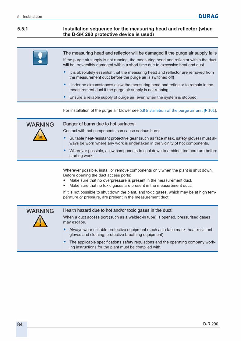
5 | Installation
84 D-R 290
Installation sequence for the measuring head and reflector (when the D-SK 290 protective device is used)
The measuring head and reflector will be damaged if the purge air supply failsIf the purge air supply is not running, the measuring head and reflector within the duct will be irreversibly damaged within a short time due to excessive heat and dust.
▶ It is absolutely essential that the measuring head and reflector are removed from the measurement duct before the purge air is switched off!
▶ Under no circumstances allow the measuring head and reflector to remain in the measurement duct if the purge air supply is not running.
▶ Ensure a reliable supply of purge air, even when the system is stopped.
For installation of the purge air blower see 5.8 Installation of the purge air unit [} 101].
WARNING Danger of burns due to hot surfaces!Contact with hot components can cause serious burns.
▶ Suitable heat-resistant protective gear (such as face mask, safety gloves) must always be worn where any work is undertaken in the vicinity of hot components.
▶ Wherever possible, allow components to cool down to ambient temperature before starting work.
Wherever possible, install or remove components only when the plant is shut down. Before opening the duct access ports:● Make sure that no overpressure is present in the measurement duct.● Make sure that no toxic gases are present in the measurement duct.If it is not possible to shut down the plant, and toxic gases, which may be at high temperature or pressure, are present in the measurement duct:
WARNING Health hazard due to hot and/or toxic gases in the duct!When a duct access port (such as a welded-in tube) is opened, pressurised gases may escape.
▶ Always wear suitable protective equipment (such as a face mask, heat-resistant gloves and clothing, protective breathing equipment).
▶ The applicable specifications safety regulations and the operating company working instructions for the plant must be complied with.
5.5.1

5 | Installation
D-R 290 85
1 Instructions for aligning the measuring head/reflector at the adjustment flange:First tighten nut B. Vertical adjustment: with nut C Horizontal adjustment: with nut A
2 Duct wall 3 Welded-in pipe with adjustment flange
4 Red dot 5 Threaded studs6 Rubber sleeve 7 12 disc springs *8 1 spherical washer * 9 1 nut *
10 measuring head (M) or reflector (R) 11 Purge air flange12 Drive 13 Fail-safe shutter14 Flat gasket * per threaded stud
Fig. 5.18: Installation at the adjustment flange, dimensional diagram D−R 290
When installing the measuring head and reflector with protective devices (fail-safe shutters) on the adjustment flange, perform the operations in the following sequence:1. Slide the gasket supplied (Fig. 5.18 - 14) on to the threaded studs of the welded-in
flanged tube.2. Also slide the D−SK 290 MA fail-safe shutter on to the threaded studs. When doing
so, align the motor housing to the side facing away from the duct and facing downwards (Fig. 5.18 - 12).
3. First pull the rubber sleeve (Fig. 5.18 - 6) over the purge air flange (11) of the measuring head or reflector.

5 | Installation
86 D-R 290
4. Connect the purge air hose to the purge air adapter of the measuring head or reflector (11) and secure it with the hose clamps supplied.Make sure that the rubber sleeve does not lie behind the hose connection (in the direction of the measuring head/reflector).
When laying the purge air hoses, note that:Standard purge air hoses are designed for a maximum ambient temperature of approx. – 25 to + 80°C. Temperatures outside this range compromise the reliability of purge air provision. Purge air hoses for other temperature ranges are available on request.Do not bend the hoses in too tight a radius in comparison to the hose diameter (risk of kinking, leading to: loss of purge air and irreparable damage to the measuring heads due to overheating).The hoses are not resistant to tension. Therefore:
▶ Do not hang the hoses in free loops under their own weight. Fit supports at reasonable intervals.
▶ Do not use force, e.g. to drag them through narrow openings in walls.
▶ Do not use hoses as attachments or supports for other objects.
D Disc springs E Spherical washerF Self-locking nut G Adjustment flange with tubeH Purge air flange
Fig. 5.19: Adjustable attachment
1. Place 12 disc springs (D) in alternate directions on each of the 3 threaded studs of the flanged tube.
2. Switch on the purge air unit (for installation of the D-BL purge air unit see 5.8 Installation of the purge air unit [} 101] ff) and slide the purge air flange of the measuring head or reflector connected to the active purge air supply on to the threaded studs (5).
3. On each stud place a spherical washer (E - flat face towards the nut)4. and on each stud only loosely tighten a self-locking nut (F) (final tightening is per
formed as part of the optical adjustment; see section 6.1 Optical alignment [} 107]).
5. Pull the rubber sleeve (6) over the space between the fail-safe shutter (13) and purge air flange (11).
6. Use the connecting cables to make the connections between the fail-safe shutters (D−SK 290 MA) and the control device (D−SK AE) and between them and the status inputs of the measuring head.
7. Enter the installation of the air flow sensor and fail-safe shutter under the respective measuring head tab (see 5.5.5 Configuring the protective device [} 92]).
8. Align the measuring head and reflector to each other; see section 6.1 Optical alignment [} 107].
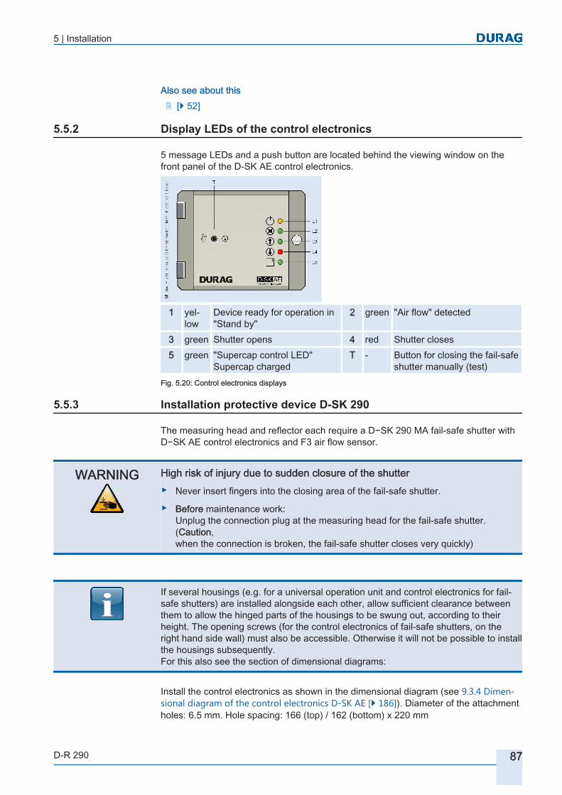
5 | Installation
D-R 290 87
Also see about this2 [} 52]
Display LEDs of the control electronics
5 message LEDs and a push button are located behind the viewing window on the front panel of the D-SK AE control electronics.
1 yellow
Device ready for operation in "Stand by"
2 green "Air flow" detected
3 green Shutter opens 4 red Shutter closes5 green "Supercap control LED"
Supercap chargedT - Button for closing the fail-safe
shutter manually (test)Fig. 5.20: Control electronics displays
Installation protective device D-SK 290
The measuring head and reflector each require a D−SK 290 MA fail-safe shutter with D−SK AE control electronics and F3 air flow sensor.
WARNING High risk of injury due to sudden closure of the shutter▶ Never insert fingers into the closing area of the fail-safe shutter.
▶ Before maintenance work:Unplug the connection plug at the measuring head for the fail-safe shutter.(Caution,when the connection is broken, the fail-safe shutter closes very quickly)
If several housings (e.g. for a universal operation unit and control electronics for fail-safe shutters) are installed alongside each other, allow sufficient clearance between them to allow the hinged parts of the housings to be swung out, according to their height. The opening screws (for the control electronics of fail-safe shutters, on the right hand side wall) must also be accessible. Otherwise it will not be possible to install the housings subsequently.For this also see the section of dimensional diagrams:
Install the control electronics as shown in the dimensional diagram (see 9.3.4 Dimensional diagram of the control electronics D-SK AE [} 186]). Diameter of the attachment holes: 6.5 mm. Hole spacing: 166 (top) / 162 (bottom) x 220 mm
5.5.2
5.5.3

5 | Installation
88 D-R 290
The D−SK AE control electronics are electrically connected to the D−SK 290 MA fail-safe shutter via a 6-core cable.
Do not make the electrical connection to the fail-safe shutter until the measuring device has been installed!
In addition an F3 air flow sensor which is installed in the purge air infeed to the measuring device and which detects any failure of the purge air is connected to the D−SK AE control electronics.The 6-core cable (2 metre length supplied) to the fail-safe shutter and the cable to the air flow sensor can be extended to 50 metres without problem (air flow sensor 3-core cable with an overall screen).
1 Air flow 2 red colour markingFig. 5.21: Air flow sensor
After removing the cover screws (PG 7), install the air flow sensor in the opening alongside the purge air connection for the measuring device so that the air flow passes through the transverse hole in the sensor. The red colour marking is an installation aid and points away from the device towards the hose (air flow).
D-SK AE electrical connection
The electrical connection to the fail-safe shutter is made using a 20‑way terminal strip in the D‑SK AE junction box as shown in the connection diagram).
5.5.4

5 | Installation
D-R 290 89
Mains (see type label)
Protective earth conductor
Purge air IN
Purge air OUT
Limit position fail-safe shutter OPEN
Limit position fail-safe shutter CLOSED
Connection stripto the driveD-SK 310 MA / D-SK 290 MA. D-SK 280 MA
externalClose shutter
Air flow sensor
sw
br
gr
no
no
no
nc
c
c
Fig. 5.22: Electrical connection to the D-SK AE
5 cable glands are available for connection of the cables. The M20 cable glands are suitable for cable diameters from 7 mm to 13 mm. The M16 cable glands are used for cable diameters between 4.5 mm and 10 mm.The cables for the mains and data cables should be routed separately.The mains supply cable should use H 07 RR – U 3 G 1.5 or the equivalent. The material of the conductors and sheath must be appropriate to the conditions at the operating site. To protect the supply conductor, a 16 A automatic circuit breaker should be installed as near to the measuring system as possible. Label the MCB so that it can be

5 | Installation
90 D-R 290
identified as the isolation switch for the device. The individual conductors of the mains power supply cable must be mutually secured in such a way that they cannot touch neighbouring terminals whilst being disconnected (e.g. using cable ties).If monitoring and control of the fail-safe shutter is performed via the measuring head, the plug end of the 8-core cable already installed should be plugged into the respective panel jack in the measuring head. The free end of the cable is connected to the respective terminals in the control device of the protective device (D−SK AE) (Fig. 5.23 ).

5 | Installation
D-R 290 91
Purge air INc
Purge air OUTc
Limit position closing shutter OPEN
Limit position closing shutter CLOSED
External shutter close
External shutter close
1 (white) 24 VDC sensor 2 (brown) Purge air inlet3 (green) S1 inlet (SSK* open) 4 (yellow) S2 inlet (SSK* closed)5 (grey) Outlet (SSK* open) 6 (lilac) Outlet (SSK* open)7 (blue) GND 8 (red) 24 VDC SSK*
(not needed for D−SK AE)*SSK = Fail-safe shutterFig. 5.23: Connection of the fail-safe shutter to the 8-core plug cable of the measuring head

5 | Installation
92 D-R 290
Configuring the protective device
After installation of all the components of the protective device (shutter, control electronics, air flow sensor) the D-R 290 measuring head configuration must be parameterised for the protective device (the presence of the air flow sensor and fail-safe shutter(s)).
Setting path:> Specific parameters > D-R 290 configuration > Purge air sensor 1 present and> Specific parameters > D-R 290 configuration > fail-safe shutter 1 present
or
> Specific parameters > D-R 290 configuration > Purge air sensor 2 present and> Specific parameters > D-R 290 configuration > fail-safe shutter 2 present
The fail-safe shutter is closed during installation and parameterisation. It opens once the air flow sensor has detected the presence of the purge air.
WARNING High risk of injury due to sudden closure of the shutter▶ Never insert fingers into the closing area of the fail-safe shutter.
▶ Before maintenance work:Unplug the connection plug at the measuring head for the fail-safe shutter.(Caution,when the connection is broken, the fail-safe shutter closes very quickly)
Checking the protective device
When the mains power is switched on (check the charge status of the supercaps [} 196]; see below) and the purge air is present, the fail-safe shutter automatically switches to the “OPEN“ position.If the power supply or the purge air fails, the fail-safe shutter of the protective device switches to the “CLOSED“ position. In this case the D‑SK AE control electronics provides the necessary power via the maintenance-free supercaps. After the failure has been rectified the fail-safe shutter automatically switches back to the “OPEN“ position. The status feedback message"Shutter OPEN“ is set at terminals 7 and 8 (connection closed) in the control electronics.The charge status of the supercaps is indicated by the green “Battery check LED“ on the front panel. When the supercaps are charged the LED lights up.The LEDs indicate only the activation, but not the shutter position. The feedback message for the shutter position is given via the cam switch in the rotary drive.
5.5.5
5.5.6

5 | Installation
D-R 290 93
The fail-safe shutter can be closed manually by pressing the push button “Hand“ (see the graphic) on the front panel of the control electronics or by parameterising the device settings:
Setting path:> Specific parameters > D-R 290 configuration > Fail-safe shutter 1 presentor> Specific parameters > D-R 290 configuration > Fail-safe shutter 2 present
to "0" via D−ESI 100 or D−ISC 100. To activate the shutter function this parameter must be reset to "1".The checking for correct operation is performed …… automatically when the D-SK AE is connected to the measuring head D−R 290. A brief test is performed every 24 hours.… manually when the D-SK AE is connected to the measuring head D−R 290 and the manual test function for the fail-safe shutter is tested.(see also section 8.2.11 Functional test of the fail-safe shutter [} 163])
Setting path:> Functions > D-R 290 Service Functions > Test Functions > Test the fail-safe shutter 1> Functions > D-R 290 Service Functions > Test Functions > Test the fail-safe shutter 2
Commissioning the D-SK AE
Before commissioning the electrical connections must be made.● via a 6−core cable between the D‑SK AE control electronics and the
D−SK 290 MA fail-safe shutter (Fig. 5.22 , Fig. 5.23 ).● via an 8−core cable between the D−SK AE and the measuring head (Fig. 5.23 ).● via the 3-core cable already installed between the air flow sensor and the D‑SK AE
control electronics (Fig. 5.22 , Fig. 5.23 )
Terminals 4 to 9, 16 and 17 must be connected to the measuring head.
Within the measuring head a shutter message must be output:
Fig. 5.24: Control electronics front panel
5.5.7

5 | Installation
94 D-R 290
Setting path:> Specific parameters > D-R 290 configuration > Purge air sensor 1 present and> Specific parameters > D-R 290 configuration > fail-safe shutter 1 present
or
> Specific parameters > D-R 290 configuration > Purge air sensor 2 present and> Specific parameters > D-R 290 configuration > fail-safe shutter 2 present
Without this message, the shutter remains closed and cannot be opened by the controller.
"Supercaps" are used for reliable closure of the shutter when the power fails. They are located on the main printed circuit board of the control electronics (D‑SK AE, on the back of the printed circuit board no. 30).The supercaps are charged automatically at commissioning and after every power supply failure. The charging procedure lasts max. 2 ½ min. The fully charged status of the supercaps is indicated by the "Supercap check LED“ (Fig. on the left - L5) on the front panel.
The fail-safe shutter will open only if the supercaps are fully charged!
The housing must be opened to set the switching points and the Hysteresis [} 195]:1. Use a screwdriver to turn the twist lock catch on the right side of the housing anti
clockwise.2. Then open the assembly frame with the transparent cover which swings open to
the left.The setting elements are now accessible.
3. Set the "Air flow"" potentiometer (P1)and the“Hysteresis“ potentiometer (P2) to the minimum (turn the potentiometers fully clockwise).✓ Once the mains power is applied the device is ready for operation. The yellow
LED (Fig. on the left - L1) “Stand by“ and the red LED (Fig. on the left - L4) “"Close shutter" light up.
4. With the purge air unit running, slowly turn the potentiometer (P1) "Air flow“ towards the maximum (turn the potentiometer anti-clockwise), until the green LED (Fig. on the left - L2) "Air flow“ lights up. Then turn the potentiometer as further 1/2 turn beyond the switch point.✓ The green LED (Fig. on the left - L3) “"Open the shutter" lights up and the fail-
safe shutter is automatically moved to the "OPEN" position.
Fig. 5.25: LED control electronics

5 | Installation
D-R 290 95
The potentiometer (P2) “Hysteresis“ adjusts the fluctuation range for the response of the D SK 290 system to a variation in the purge air flow from the air flow set by P1. If the fluctuation range is set too small, the protective shutter will open and close continually.
P1 air flow
P2 hysteresis
Fuse
Fig. 5.26: D‑SK AE control electronics
After the settings for commissioning have been made, the housing should be closed:1. Close the hinged assembly frame with the transparent cover.2. Use a screwdriver to turn the twist lock catch on the right side of the housing clock
wise.The operation of the fail-safe shutter whilst the device is in operation can be performed by briefly switching off the purge air supply or by disconnecting the purge air hose.There will be a delay before the shutter closes, because the air flow monitor detects the failure of the purge air only at intervals given by a time constant.If the commissioning has been performed correctly but the shutter does not operate, the motor current protection switch in the housing of the shutter motor may have tripped.To reactivate the motor current protection switch, undo the two socket-head screws on the cover of the motor, remove the cover and push the actuation button on the motor current protection switch back in.If the shutter does not open or close within 3 minutes, the measuring head sets a "shutter blocked" flag. The connection between terminals 16 and 17 (see Fig. 5.22 ) is then opened so that the shutter closes. This safety function can be deactivated by resetting the blocking message e.g. by using the D-ESI 100 software or by restarting the measuring head.
Setting path:> Specific parameters > D−R 290 device status > Fail-safe shutter > Fail-safe shutter 1 blocked and deactivated
or
> Specific parameters > D−R 290 device status > Fail-safe shutter > Fail-safe shutter 2 blocked and deactivated
Resetting the blocking message to the value "0" restores the connection of the terminals16 and 17 through the measuring head.
Motor currentprotectionswitch
Fig. 5.27: Shutter motor

5 | Installation
96 D-R 290
Installation of the D-ISC 100 control unit
For installation of the optional D-ISC 100 control unit and for further information about it please refer to the operating manual for this control unit.
Connecting the supply and control unit
The measuring device D‑R 290 can be operated in three different modes, using the D‑TB 100 supply unit and/or the D‑ISC 100 control unit:● As a stand-alone device with only one D‑TB 100 and no control unit (Fig. 5.28 ). In
this case, operation is performed using Modbus or a PC, laptop or tablet, using the D‑ESI 100 operating software .
Fig. 5.28: Connecting the D−R 290 as an individual sensor to the D‑TB 100 supply unit● Directly supplied by the D−ISC 100 control unit at the sensor level (Fig. 5.29 ). In
this case the D‑R 290 is supplied with power directly by the D‑ISC 100, and no D‑TB 100 is required. The maximum permissible length of this connecting cable is 12 m.
Fig. 5.29: Connecting the D−R 290 as an individual sensor directly to the D‑ISC 100 control unit
5.6
5.6.1

5 | Installation
D-R 290 97
● With the D‑ISC 100 control unit at field node level and the power supply of the D‑R 290 provided by a D‑TB 100 (Fig. 5.30 ). In this configuration the control unit can be up to 1000 m from the device and also be used for operating other DURAG Bus devices.
Fig. 5.30: Supplying the D−R 290 via a D-TB 100 and connection of a D‑ISC 100 via DURAG Bus
Installation of the supply unit
The power supply of the D−R 290 measuring system is provided by a D−TB 100 supply unit.A blower is also required for the purge air.
Installation of the D-TB 100 supply unit
The D-TB 100 supply unit is installed close to the measuring point (ensure the pre-installed connection cable reaches it; see delivery note). The dimensional drawing for the D-TB 100 supply unit, showing the positions of the attachment holes can be found on page 9.3.6 Dimensional diagram supply unit (terminal box) D-TB 100 [} 187] in Fig. 9.11 .
5.7
5.7.1
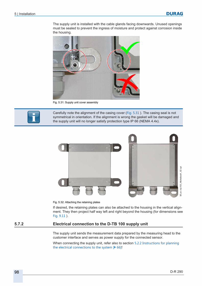
5 | Installation
98 D-R 290
The supply unit is installed with the cable glands facing downwards. Unused openings must be sealed to prevent the ingress of moisture and protect against corrosion inside the housing.
Fig. 5.31: Supply unit cover assembly
Carefully note the alignment of the casing cover (Fig. 5.31 ). The casing seal is not symmetrical in orientation. If the alignment is wrong the gasket will be damaged and the supply unit will no longer satisfy protection type IP 66 (NEMA 4.4x).
Fig. 5.32: Attaching the retaining plates
If desired, the retaining plates can also be attached to the housing in the vertical alignment. They then project half way left and right beyond the housing (for dimensions see Fig. 9.11 ).
Electrical connection to the D-TB 100 supply unit
The supply unit sends the measurement data prepared by the measuring head to the customer interface and serves as power supply for the connected sensor.When connecting the supply unit, refer also to section 5.2.2 Instructions for planning the electrical connections to the system [} 66]!
5.7.2

5 | Installation
D-R 290 99
DANGER High voltage. Risk of fatal injury due to electric shock!Touching live parts poses an immediate risk of fatal injury.
▶ Permit only qualified electricians to work on electrical equipment.
▶ Before opening the casing of a device or removing a guard protecting against touching it, deenergise the device, test it to ensure it is electrically dead and secure it against switching on again.
In all installations, ensure compliance with the applicable local regulations and any supplementary regulations issued by the local power supply companies.
1. Loosen the four (captive) screws and open the supply unit.Spring terminals are provided in the supply unit for connecting the data cable screens. These terminals can be released using a hexagon socket key, moved to the available tapped holes on their rail (Fig. 5.33 – 1) if required and also changed to a different direction.
1 Tapped hole 2 Recess in the spring terminalFig. 5.33: Connecting the cable screen
1. Strip back approx. 20 mm of the screen.2. Using a suitable tool (e.g. a screwdriver), depress the spring terminal into the re
cess ( Fig. 5.33 – 2) provided for this and insert the screen between the jaws of the terminal.
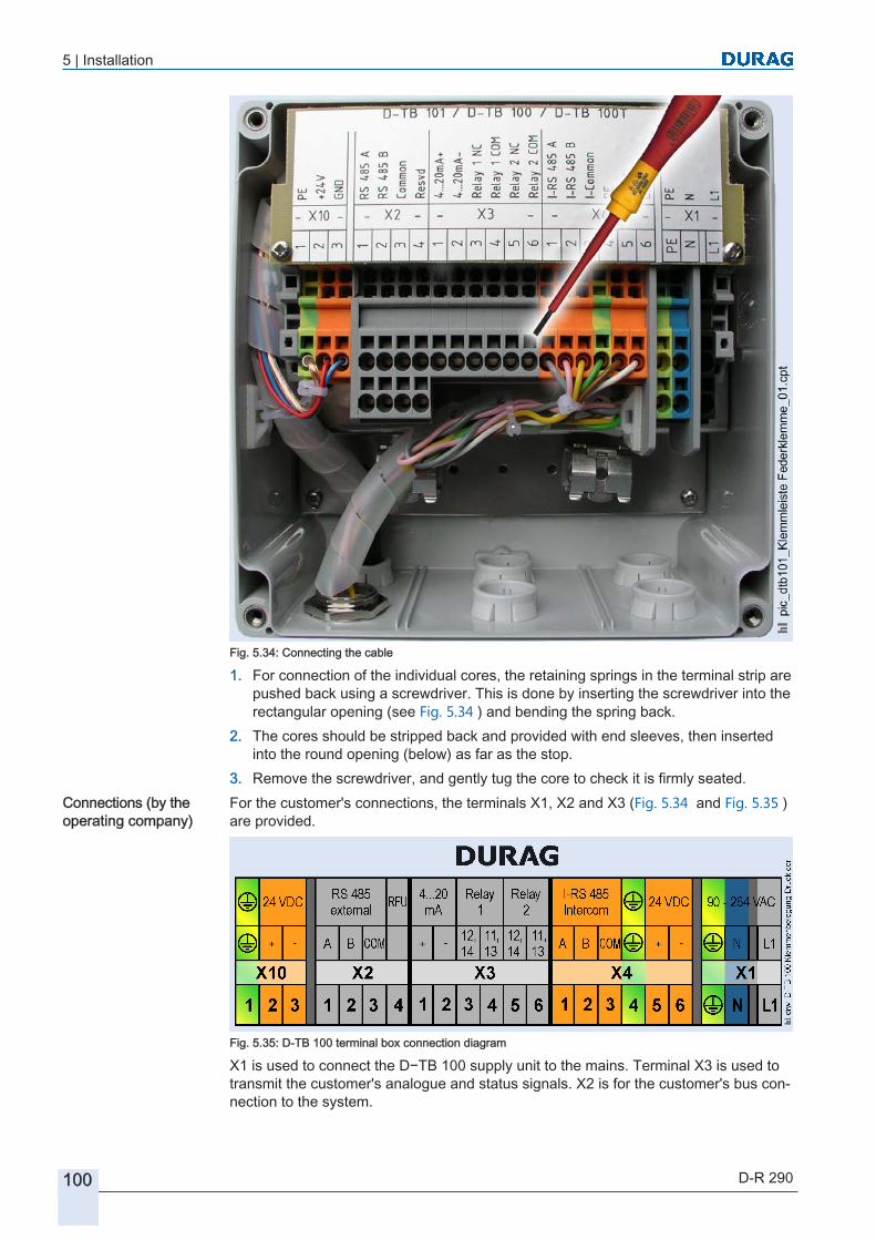
5 | Installation
100 D-R 290
Fig. 5.34: Connecting the cable
1. For connection of the individual cores, the retaining springs in the terminal strip are pushed back using a screwdriver. This is done by inserting the screwdriver into the rectangular opening (see Fig. 5.34 ) and bending the spring back.
2. The cores should be stripped back and provided with end sleeves, then inserted into the round opening (below) as far as the stop.
3. Remove the screwdriver, and gently tug the core to check it is firmly seated.For the customer's connections, the terminals X1, X2 and X3 (Fig. 5.34 and Fig. 5.35 ) are provided.
Fig. 5.35: D-TB 100 terminal box connection diagram
X1 is used to connect the D−TB 100 supply unit to the mains. Terminal X3 is used to transmit the customer's analogue and status signals. X2 is for the customer's bus connection to the system.
Connections (by the operating company)

5 | Installation
D-R 290 101
The cables to terminal X10 are pre-wired by the factory for the measuring heads. The practical connection to the measuring heads is then performed via a plug connector.
When connecting the conductors to the terminals, make absolutely sure you use the relevant twisted pairs of the cable for the associated conductors (e.g. RS 485 A and B, 4..20mA + and –, relay 1 NC and COM, etc.)!
Close the supply unit and tighten the four (captive) screws.In order to maintain protection type IP 66 (NEMA 4.4x) any cable glands that are not used must be securely sealed using suitable plugs.
Installation of the purge air unit
A purge air unit (blower) is required for supplying the device with purge air.Purge air units are used to reduce contamination of the outer optical faces and to provide thermal protection of the device against exhaust gases. Even at plants with a natural operational vacuum, a purge air unit is required, because the device may become contaminated if the boiler is shut down, the suction intake fails or during start-up.
Selection of an installation location of the purge air unit (blower)
The following points must be observed when selecting the installation location:
Damage as a result of blocked intake openings / purge air hoses!The inlet opening must not be blocked or covered over by deposits of leaves, sand, dirt, snow or the like.It can also make sense to guard against ingress by small animals and insects so as to avoid them causing interruptions in the purge air supply
▶ Fit the intake air hose so that no water, dirt or dust can accumulate in the hose.
▶ See technical data (e.g. ambient temperature and protection type) – see the appendix!
● The intake air must be as free of dust and as dry as possible.● The temperature of the intake air must be within the range -20 to +40°C.● Sufficient clear space must be available for filter replacement (see Fig. 9.12 , sec
tion 9.3.7 Dimensional diagram purge air unit D-BL [} 188]).● A weather protection cover type D‑BL WSHN is available for outdoors installation
of the purge air unit.The purge air unit can be attached to the rear wall using the 4 attachment holes (see Fig. 9.12 upper illustration).
Arrangement and installation of the purge air unit
The purge air unit is mounted on a compact stainless steel baseplate (material no. 1.4301) (see also 9.3.7 Dimensional diagram purge air unit D-BL [} 188]).
5.8
5.8.1
5.8.2

5 | Installation
102 D-R 290
The pure air unit is supplied with 10 m of purge air hose Ø 40mm, temperature range – 25 to + 85°C.The optional weather protection cover type D‑BL WSH is also made of stainless steel (material no. 1. 4301).
Electrical installation of the purge air unit
During electrical installation of the purge air unit, note the following: 1. The local mains voltage and frequency must be compared to the data on the type
label. Connect the unit only if the data match.2. Connect the protective earth conductor to the earthing terminal.3. Perform the connection and arrangement of the jumpers according to the connec
tion schematics in the terminal box lid.4. Set the motor protection switch (not supplied) to the rated current of the motor.5. The direction of rotation of the blower motor must be checked.For technical data of the purge air unit see the Appendix.
The measuring head and reflector will be damaged if the purge air supply failsIf the purge air supply is not running, the measuring head and reflector within the duct will be irreversibly damaged within a short time due to excessive heat and dust.
▶ It is absolutely essential that the measuring head and reflector are removed from the measurement duct before the purge air is switched off!
▶ Under no circumstances allow the measuring head and reflector to remain in the measurement duct if the purge air supply is not running.
▶ Ensure a reliable supply of purge air, even when the system is stopped.
It is therefore recommended that the purge air unit is provided with a separate fuse.
Electrical connection for the purge air motor
drw
_D-B
L xx
x_E
lekt
risch
e A
nsch
lüss
e S
püllu
ftein
heit_
0004
_S1
L1 N
U3 U2 Z4U1 1/2CA1 U4
Erde Ground
Z2Z3
Z11/2CA1
1/2CA2CB
Typ D-BL 1-00 ...115 V
L1 N
U3 U2 Z4U1 1/2CA1 U4
Erde Ground
Z2Z3
Z1
1CA1
1CA2 2CA1
2CA2CBCB
Typ D-BL 1-00 ...230 V
Fig. 5.37: Electrical connection for the purge air motor
Also see about this2 Personnel, skills [} 22]
5.8.3
5.8.4
Fig. 5.36: Junction box

5 | Installation
D-R 290 103
Active operation
Once the power for the power supply unit and the purge air unit has been switched on, the D‑R 290 measuring system operational. No special operator control is required while the system is in operation. To end the operation, the device connection cable can be unplugged from the supply unit or the universal operation unit. However the purge air supply must continue to be ensured.
The measuring head and reflector will be damaged if the purge air supply failsIf the purge air supply is not running, the measuring head and reflector within the duct will be irreversibly damaged within a short time due to excessive heat and dust.
▶ It is absolutely essential that the measuring head and reflector are removed from the measurement duct before the purge air is switched off!
▶ Under no circumstances allow the measuring head and reflector to remain in the measurement duct if the purge air supply is not running.
▶ Ensure a reliable supply of purge air, even when the system is stopped.
Dismantling and disposal
Dismantling
DANGER High voltage. Risk of fatal injury due to electric shock!Touching live parts poses an immediate risk of fatal injury. Damage to the insulation or to individual components can lead to fatal injury.
▶ If there is any damage to the insulation, switch off the power supply immediately and have it repaired.
▶ Permit only qualified electricians to work on electrical equipment.
▶ Before opening the casing of a device or removing a guard protecting against touching it, deenergise the device, test it to ensure it is electrically dead and secure it against switching on again.
▶ Keep moisture away from live components. This can lead to short circuits.
1. Dust and Opacity Monitor Disconnect the device from the mains and check that it is deenergised.
2. Undo all plug connectors connected to the respective measuring head.3. Open the supply unit.4. Disconnect the of the Dust and Opacity Monitor from the electrical power by dis
connecting the wires at the terminal strip.5. Use a suitable tool (such as a screwdriver) to depress the spring terminal into the
recess provided. Pull the cable and screen out from the clamping jaws.6. Uninstall the cables that were used,7. Dust and Opacity Monitor and remove the measuring head from the operating
company's overall system at an organisational level.
5.9
5.10
5.10.1

5 | Installation
104 D-R 290
Disposal of the Dust Concentration and Opacity Monitor
Disposal of used electrical and electronic devices(to be applied in European Union countries and other European countries with a separate collection system for these devices)
This product is not to be treated as normal domestic waste. It must be taken to a collection point for the recycling of electrical and electronic devices. Your contribution to the correct disposal of this product protects the environment and the health of your fellow man. Irresponsible disposal places the environment and our health at risk. Materials recycling helps reduce the consumption of raw materials. Current information on the recycling of this product can be obtained from your local authority and municipal waste management agency.
RoHS compliance
The DURAG product D‑R 290 Dust and Opacity Monitor complies with the RoHS [} 196].
5.10.2
5.10.3

D-R 290Dust Concentration and Opacity Monitor of the
Second Generation
66 Commissioning
6.1 Optical alignment
6.2 Parameterisation and operation of the measuring head
6.3 Navigation help for D-ESI 100 settings path
6.4 Information on the DURAG Modbus protocol6.4.1 Basic Modbus information
6.5 Example: Save parameters
6.6 Using the PIN lock (PIN code)6.6.1 PIN symbol overview
6.6.2 Example: Login
6.6.3 Example: Change PIN code
6.6.4 Example: Logout
6.6.5 Example: Deactivate the PIN lock
6.7 Parameter checking or setting overview

106 D-R 290

6 | Commissioning
D-R 290 107
Commissioning
Preconditions for operation (checklist)
Has the supply unit been installed, connected to the power supply and is it in operation?
❑
Has the measuring head and reflector purge air supply been ensured? ❑Are the measuring head and reflector mounted on the flue stack? ❑Has the cabling been performed as specified? See section● 5.7.2 Electrical connection to the D-TB 100 supply unit [} 98]● 5.8.3 Electrical installation of the purge air unit [} 102], 5.8.4 Electrical con
nection for the purge air motor [} 102]● 5.5.4 D-SK AE electrical connection [} 88]
❑
WARNING Danger of injury due to insufficient skills!Incorrect use can result in serious personal injury and material damage.Only ever have work performed by suitably qualified specialised personnel! Ensure compliance with the skills and knowledge described in section 2.4.1 Personnel, skills [} 22].
Possible damage to the measuring head and reflector due to hot gases and dust in the ductUnder no circumstances operate the measuring head and reflector unless the purge air supply to the flange and dust duct is running. If the purge air supply is not running, the measuring head and reflector will be irreversibly damaged within a short time due to excessive heat and dust.
Optical alignment
After installation on the stack, the measuring system must be optically aligned. The measuring system is factory-set to the measuring path length specified by the operating company. Therefore there is no need to open the system in order to make further settings. If the measuring system has not yet been aligned to the corresponding measuring path length, or if the measuring system is subsequently installed on a measuring section of a different length, after adjustment a calibration to the dust free measuring path must be performed (see 7.7.8 Calibration on the dust-free measuring path [} 146]).It is advisable that the optical alignment is done in the following sequence:1. Make the electrical connections to the measuring head and supply unit / control
unit.Switch on the power.After the power has been switched on, the measuring system performs an LED comparison measurement and a contamination check measurement. It then switches into measurement mode and is thus ready for operation.
6
6.1

6 | Commissioning
108 D-R 290
2. Once the measuring head and reflector have been installed as shown in Fig. 5.10 or Fig. 5.18 , the 3 nuts on the respective flanges are tightened as described in the points below.
3. By this means the optical alignment of the measuring head is performed at the same time.For this a sighting mechanism (Fig. on the left middle) is available on the measuring head, which is located on the right side behind a sight glass. The image of the reflector (spot of light) must be aligned so that it is positioned in the centre of the sighting mechanism (see figure on the left, bottom). If necessary the reflector must also be aligned (at right angles to the gas duct).
4. Now nut B is tightened first (Fig. on the left, top).When the nut A is tightened, the measuring head changes its inclination relative to the axis B - C and the image in the sighting mechanism moves in a horizontal direction. Tightening or releasing the nut C causes a pivoting movement about the axis A - B and the image in the sighting mechanism moves in the vertical direction.
Only tighten the (self-locking) nuts to such a degree that the disc springs can still perform their spring action.
Parameterisation and operation of the measuring head
The device is supplied with factory settings. The calibration to the dust-free measuring path is performed in the factory provided that the operating company has supplied a completed measuring point questionnaire. After successful initial commissioning, the parameterisation of the measuring head must be performed by software. The basic parameters necessary for operation must be saved.DURAG service technicians will be glad to assist you if required. They have the necessary equipment and software. You can find the addresses and phone numbers of the service engineers under DURAG GROUP company addresses.Specific hardware and software are required for inputting or checking parameters. We recommend the use of the optional D‑ESI 100 SET.The standard interface for parameterisation is the USB port. To allow the use of this port, the protective cap must be opened on the USB port of the measuring head (see Fig. 5.12 ).
Fig. 6.1: Sighting mechanism
Fig. 6.2: Optical alignment
6.2

6 | Commissioning
D-R 290 109
The D−ESI 100 SET includes a USB cable with a Mini-B 5-pin plug. Insert this plug into the USB port accessible at the rear of the casing; it is then connected to the measuring head. Insert the other end of the USB cable into the PC to make the connection.Using the USB port allows only one device, the one actually connected, to be addressed at any given time. For parameterisation, the software for the D−ESI 100 SET is used (supplied on the USB memory stick). More details on D−ESI 100 and how to carry out the following settings with the Engineering and Service Interface can be found in the D−ESI 100 manual.Alternatively the sensor can also be activated via the DURAG Modbus. Information on the DURAG Modbus protocol are described in section 6.4 Information on the DURAG Modbus protocol [} 110].
Navigation help for D-ESI 100 settings path
Navigation help for D‑ESI 100If necessary at the start of each description you will find a box "D‑ESI 100 setting path". It shows the path to the relevant menu in the setting software where you can perform the listed checks/settings (see below).
Setting path:
Sitemap > »Device (e.g. D−FL 220) > > Common Parameters > Bus In
formation > Current date and time >
The device overview page containing the device list (see figure below) is always the startpoint:
Fig. 6.3: Device list
Example for the path information in the D‑ESI 100 path above:The box summarises in abbreviated form the following action steps:
1. Click on »Device in the sitemap. Click on the symbol in the device list for the desired device (in this example the top device in the list: D−FL 220).
2. In the menu that appears, click on the tab "Common parameters" (active tabs have a blue background).
3. You will find a list field under “Select group”. Click there on the ▼ arrow and select "Bus Information".
4. In the table which is now visible, click on the symbol in the "Current date/time” line (at the end of the line).
6.3

6 | Commissioning
110 D-R 290
Information on the DURAG Modbus protocol
This information is intended for operating and maintenance personnel who already have the necessary basic information technology and networking knowledge:● The Modbus protocol is a communications protocol. Since 1979, because of its
open structure, Modbus has become a de facto standard in the industry.● The data are transmitted in binary form. This form of the Modbus is designated as
RTU.● The DURAG Modbus is based on the Modbus protocol, and also defines additional
information, such as register assignments.● The D‑ISC 100 uses a RS-485 serial interface [} 196] to the DURAG Modbus
specification.We have summarised in the appendix the most important technical data that you require for the D‑ISC 100 - Universal control unit in relation to the Modbus (see Setting the addresses (slave addresses)).
Basic Modbus information
Basic information about the Modbus RTU [} 195] Modbus can be obtained from the Internet at the home page of the Modbus Independent User Organisation (IDA)*.● "Modbus Protocol specifications"http://www.modbus.org/docs/Modbus_Application_Protocol_V1_1b.pdf(Describes the datagrams (protocol data units) that are exchanged between master and slave).● "Modbus over Serial Line Specification and Implementation Guide"http://www.modbus.org/docs/Modbus_over_serial_line_V1_02.pdf(Describes how the datagrams are packed into telegrams (application data units)).The specifications of the cables to be used for operating the Modbus can be found on the Internet under the address*● http://www.modbus.org/docs/Modbus_over_serial_line_V1_02.pdfin the Chapter 3.6 Cables.● http://modbus.org/docs/Modbus_Messaging_Implementa
tion_Guide_V1_0b.pdfInformation on using Modbus TCP.*(DURAG GmbH offers no guarantee of the correctness of the Internet addresses. DURAG GmbH offers no guarantee of the correctness of the pages listed. The presenters of those pages take sole responsibility for them).
Example: Save parameters
6.4
6.4.1
6.5
» Device» Options» Data log» Login

6 | Commissioning
D-R 290 111
Setting path:
Sitemap > »Device (e.g. D‑R 290 ) > > Save Parameters
For security reasons, parameters that are changed (e.g. specific parameters such as data for gravimetric calibration) are initially written only to the working memory of the device. This means these data are currently used or referenced, but are no longer available after the device has been restarted (i.e. the device then reverts to using the "old" parameters).Clicking on the "Save parameters" button causes the data to be transferred to the read-only memory of the device. This means the parameters are also retained and continue to be used even the device is restarted.
On the device details page, left click on the "Save parameters" button
Using the PIN lock (PIN code)
The measuring head of the D‑R 290 can be locked with a PIN code against accidental changes to the parameters that affect the measurement (see also D‑ESI 100 Operating manual).The PIN code is deactivated when the devices are delivered.
Fig. 6.4: PIN lock deactivated
Also see about this2 Example: Login [} 112]
PIN symbol overview
D‑ESI 100 uses the following symbols in conjunction with the PIN code:
Symbol MeaningChange the PIN (only for the device currently displayed)
PIN lock deactivated (device not protected)
PIN lock active -> protected parameters locked (device protected)
PIN lock active -> protected parameters enabled (device has been unlocked using a valid PIN code)PIN lock active -> protected parameters not enabled (an invalid PIN code was used for the current device)Remedy: Log out and log in against with the PIN code valid for the device.
Step 1
Save parameters
6.6
6.6.1

6 | Commissioning
112 D-R 290
Symbol MeaningEdit parameters that do not have a PIN lock
Edit parameters that do have a PIN lock (to edit these parameters, it is necessary to enter a valid PIN code)
Table 6.1: PIN symbol overview
Example: Login
Setting path:
Sitemap > »Login
Left click on "Login" in the sitemap.This calls up the login box for inputting the PIN code.
Fig. 6.5: Login box
The login name generally adopted is "user". The entry is not case-sensitive.PIN / password for a device where the PIN code is deactivated is "0000" (four zeros). Enter four zeros.After entering this, login is completed by a left mouse click on the "Login" button or
with the Enter key
The "Change PIN code" button and the symbol with the same name also appear on
the device overview page .
6.6.2
» Device» Options» Data log» Login
Step 1
Step 2Step 3

6 | Commissioning
D-R 290 113
Fig. 6.6: D-ESI 100 device overview page after login
Inputting the login name/PIN combination "user/0000" always takes you to the dialogue box where you can change the PIN code. Access to one or more protected devices is however available only once you have entered the current PIN code for the respective devices on the login page!
Example: Change PIN code
See also section: Logging in (in the D−ESI 100 manual)
Setting path:
Sitemap > »Login (user/0000) > "Login"
device (e.g. D‑R 290 ) >
Fig. 6.7: D-ESI 100 device overview page after login
The "Change PIN code" button assigns a new PIN code to all the devices listed on the device overview page at once (for restrictions see below under "pre-conditions").The "Change PIN code" symbol only assigns a new PIN code to the device listed on the device overview page whose "Change PIN code" symbol you clicked on (for pre-conditions see the section "Change PIN code" in the D−ESI 100 manual).
● You logged in with PIN code "0000" (four zeros) and …you are connected by USB cable to an unprotected device or …
● You logged in …○ with PIN code "0000" (four zeros) and …○ selected an unprotected device via the existing DURAG − Modbus connection in
the device overview page and…○ then clicked on the symbol to call up the device details page or…
6.6.3
» Device» Options» Data log» Login
Change PIN code
Pre-condition:
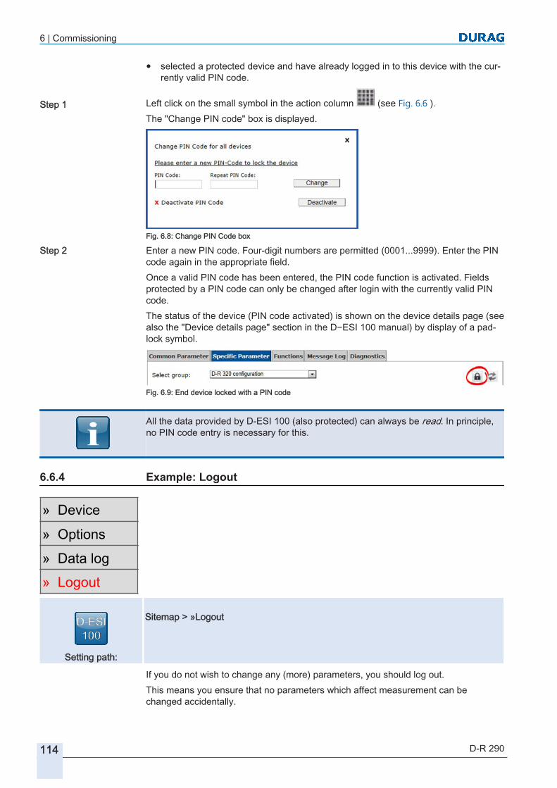
6 | Commissioning
114 D-R 290
● selected a protected device and have already logged in to this device with the currently valid PIN code.
Left click on the small symbol in the action column (see Fig. 6.6 ).The "Change PIN code" box is displayed.
Fig. 6.8: Change PIN Code box
Enter a new PIN code. Four-digit numbers are permitted (0001...9999). Enter the PIN code again in the appropriate field.Once a valid PIN code has been entered, the PIN code function is activated. Fields protected by a PIN code can only be changed after login with the currently valid PIN code.The status of the device (PIN code activated) is shown on the device details page (see also the "Device details page" section in the D−ESI 100 manual) by display of a padlock symbol.
Fig. 6.9: End device locked with a PIN code
All the data provided by D‑ESI 100 (also protected) can always be read. In principle, no PIN code entry is necessary for this.
Example: Logout
Setting path:
Sitemap > »Logout
If you do not wish to change any (more) parameters, you should log out.This means you ensure that no parameters which affect measurement can be changed accidentally.
Step 1
Step 2
6.6.4
» Device» Options» Data log» Logout

6 | Commissioning
D-R 290 115
To log out, simply left click on "Logout” in the site map.
Auto logoutIf the PIN lock is activated, a user that is logged in is automatically logged out if the system has not recorded any user activity within one hour.
Example: Deactivate the PIN lock
The PIN code can be deactivated only by a user who is logged in.Refer to section 6.6.2 Example: Login [} 112]
Left click on the "Change PIN Code" button or on the small symbol in the Action col
umn (see also Fig. 6.6 ).The "Change PIN Code" box is displayed.
Fig. 6.10: Deactivate the PIN code
Left click on the "Deactivate" button.
D‑ESI 100 Successful completion of the change is reported in a dialogue box.
Fig. 6.11: PIN Code changed successfully
In the bottom area, under the "Protocol" heading, there is a green tick. If you hover the mouse cursor over this tick you are shown the message Quick Info [} 196] "PIN code changed successfully". That means in this case that the PIN code has been deactivated."Protocol" is not a link, no protocol can be called up by clicking on it. The data available and the green tick are the protocol!The dialogue box can be closed (only) by clicking on the × (at the top right of the box).
Step 1
6.6.5
Step 1
Step 2
Success

6 | Commissioning
116 D-R 290
Once the PIN code has successfully been deactivated, the device is now no longer protected against accidental changes. The appropriate symbol (padlock crossed out) is shown on the device detail page (see Fig. 6.12 ).
Fig. 6.12: PIN lock deactivated
In the bottom area, under the "Protocol" heading, there is a red cross. If you hover the mouse cursor over this tick you are shown the message Quick Info [} 196] "Change PIN code failed". That means in this case that the old PIN code remains active.
Fig. 6.13: Change PIN code failed
"Protocol" is not a link, no protocol can be called up by clicking on it. The data available and the red cross are the protocol!The dialogue box can be closed (only) by clicking on the × (at the top right of the box).If the PIN code was not successfully changed (deactivated), the device is still protected against accidental changes. The old PIN code for the device remains valid!
Parameter checking or setting overview
The following table shows which parameters must be checked and set. The individual operations are listed in functional sequence one after the other. The right-hand column in the table indicates the section which contains detailed information about the respective check / setting.At the start of this section you will find a box "D‑ESI 100 setting path" which shows the path to the relevant menu in the setting software in which you can perform the listed checks/settings.
Key word Range Component see section1 Date, time* Bus information current date/time
● set (manually)● synchronise time
7.2 Example: Settings for checking / synchronising: Date and time [} 120]
2 Digitalcommunication(DURAG−Modbus)*
Bus information Modbus addressModbus communicationsettings
7.3 Example: Setting – DURAG – Modbus address [} 121]7.4 Example: Baud rate settings [} 122]
unsuccessful
6.7

6 | Commissioning
D-R 290 117
Key word Range Component see section3 Measured value out
put separately in each case for channels 1…4
Variables setting
Type codeLimit valuesMeasured value correctionIntegration timeSignal rangeOutput the control cycle(settings)Zero range
7.5 Example: Setting variables for the measurement channels (channel #1)… (channel #4) [} 125] and the followingsection
4 Analogue output andrelay settings
Analogue output and relay settings
Analogue output settings● Channel for analogue
output● analogue output range**Relay settings● Relay 1● Relay 2● Relay logic
7.6 Example: Assignment of the device outputs [} 134]
5 Maintenance settings*
Maintenance settings
Reference point test setpoint(Duration of the controlcycle stepControl cycle intervalFault indication suppression)
7.7 Maintenance setup [} 139]
6 Test and simulationfunctions
Functions Simulation of the analogue output fixed value, simulation of the measurement channels, simulation of the digital outputs
Table 6.2: Checklist for parameter checking (general)
Other entries are device-specific:
Key word Range Component see section7 Device configuration Device-specific
settingsDevice variant,fail-safe shutter fitted
Device configuration
8 Measured values Device-specificsettings
Contamination, zero point value, reference point value
7.7.5 Measured values [} 142]
9 Settings Device-specificsettings
Data for gravimetric calibration, stack correction factor, measurement path length
7.7.6 Settings [} 142]
10 Device status Device-specificsettings
Device status, device temperatures, purge air flow, fail-safe shutter position
7.7.7 Device status: [} 143]
11 Maintenance andservice functions
Functions Control cycle, contamination check, zero point check and reference point check
8.2.10 Control cycle [} 162], 8.2.8 Contamination check [} 161], 8.2.7 Zero point check [} 161], 8.2.9 Reference point check [} 162]
12 D-R 290 Checking the linearity
Functions Checking the linearity 8.2.6 Checking the linearity [} 158]

6 | Commissioning
118 D-R 290
Key word Range Component see section13 D-R 290 Service
FunctionsFunctions Calibration to the dust-free
measuring path, test function for the fail-safe shutters
7.7.8 Calibration on the dust-free measuring path [} 146]
* only if necessary** corresponds to the setting of the signal range of the channel for analogue output
Table 6.3: Checklist for parameter checking (device-specific)

7 | Checking / setting parameters with D‑ESI 100
D-R 290 119
Checking / setting parameters with D‑ESI 100 The procedures for setting parameters of the measuring head(s) using the software D‑ESI 100 (optional ) are described in the following sections. If necessary at the start of each description you will find a box "D‑ESI 100 setting path. It shows the path to the relevant menu in the setting software where you can perform the listed checks/settings.
D−ESI 100 help function
D‑ESI 100 is intuitive to use. It was therefore possible to do without an elaborate help function. Instead of that, information is overlaid as so-called Quick Info [} 196].Quick info provides information while you are working with the program and inputting data.Simply hover the cursor over a pictogram (provided with quick info) whose function you would like to get information about (see below, left-hand image). All symbols and pictograms are generally provided with quick info of this kind.
Table 7.1: D-ESI 100 quick info
Further information on topics such as inputting parameters can also be obtained as
quick info if you hover the cursor over an " symbol" (see above, right-hand im
age). You can get additional descriptions if you hover the cursor over a " symbol".
If at any time the Quick Info is not displayed, left-click in a free area of the screen.Then hover the cursor again over the place where you require information.
You can get information about the program (as otherwise under Help>Info or Help>About program or similar) as Quick Info, if you hover the cursor over "version"in the bottom right-hand corner of the window.
Fig. 7.1: Info about D−ESI 100
7
» Device» Options» Data log» Login7.1
Help
Program version

7 | Checking / setting parameters with D‑ESI 100
120 D-R 290
Example: Settings for checking / synchronising: Date and time
Setting path:
Site map > »Device (e.g. D‑R 290 ) > > Common parameters > Bus in
formation > Current date/time >
Fig. 7.2: Setting the date/time
The D‑R 290 has an internal clock (in the measuring head). It is necessary that the clock is correctly set for recording messages in the message logbook and for access to settings.A specific desired date/time input can be saved in the device (e.g. the system works in more than one time zone). After this has been input, the time can however no longer be synchronised (see above); otherwise the input will be overwritten again by the system time!
Parameters DescriptionCurrent date/time Standard format: 22.08.2011 13:29:28
Set/correct the time
Left click on "device" in the site map.
Left click on for the desired device in the device list.
Under Common parameters in the list field after "Select group" set "Bus information".
Left click on the "Edit" symbol in the line for which you wish to change the "Current date/time".Perform direct keyboard input to correct the date and/or time in the "value" column, using the specified format.
Synchronising the timeIn order to achieve synchronous time input between the time data for any monitoring system that may be used and the time data for the message logbook, the device time can be synchronised with the system time (PC time).
Left click on "device" in the site map.
7.2
Step 1Step 2
Step 3
Step 4
Step 5
Step 1

7 | Checking / setting parameters with D‑ESI 100
D-R 290 121
Left click on the in the device list on the device for which the time is to be synchronised, on the device parameter Click on the "Synchronise time" button.
All parameters that are changed must then be permanently saved. For this, see (in the D‑ESI 100Manual) Chapter "6.5 Example: Save parameters [} 110]".
The detailed procedure for setting parameters is described in the D‑ESI 100Manual.
Example: Setting – DURAG – Modbus address
The available address range is from 1 to 247.The default address is: 25 .Comply with the Modbus rules for the use of addresses!
Setting path:
Sitemap > »Device (e.g. D‑R 290 ) > > Common Parameters > Bus In
formation > Modbus Address, Value >
Fig. 7.3: Setting DURAG − Modbus address
Setting DURAG − Modbus address in the device
Left click on "Device" in the sitemap.
Left click on for the desired device in the device list.
Under Common parameters in the list field, after "Select Group" set "Bus information".
Left click on the "Edit" symbol in the "Modbus address“ line.
Using the number keys, correct the Modbus address there in the "Value" column.
Step 2
Step 3
synchronise time
7.3
Step 1Step 2
Step 3
Step 4
Step 5

7 | Checking / setting parameters with D‑ESI 100
122 D-R 290
Setting path:
Sitemap > »Device (e.g. D‑R 290 ) > > Save Parameters
For security reasons, parameters that are changed (e.g. specific parameters such as data for gravimetric calibration) are initially written only to the working memory of the device. This means these data are currently used or referenced, but are no longer available after the device has been restarted (i.e. the device then reverts to using the "old" parameters).Clicking on the "Save parameters" button causes the data to be transferred to the read-only memory of the device. This means the parameters are also retained and continue to be used even the device is restarted.
The procedure for inputting the DURAG − Modbus address and also the baud rate is different from the one used for all other data inputs. So as not to break off Modbus communication between the device and the PC, the new address is at first written only to the register. It is not yet brought into use! The new address is not transferred to the read-only memory of the device (EEPROM) until it has been saved. And only after a restart of the device does the new address also become active i.e. used (see below, saving parameters, restarting the device).
Setting path:
Sitemap > »Device (e.g. D‑R 290 ) > > Save parameters Sitemap > »Device (e.g. D‑R 290 ) > > Restart device
So that the new DURAG − Modbus address can be used, left click on the "Save parameters" button.
Finally the device must be restarted in order to use the new DURAG Modbus address.To do this, left click on the "Restart device" button.
From now on, the device will use the new DURAG − Modbus address.
Example: Baud rate settings
For the baud rate of the RS-485 interface, you can choose between four different settings.
Parameters DescriptionBaud rate Optionally: 9600bd, 19200bd, 38400bd, 57600bd
» Device» Options» Data log» Login
Step 6
Save parametersStep 7
Restart device
7.4

7 | Checking / setting parameters with D‑ESI 100
D-R 290 123
The default is 19200 Baud.
Comply with the Modbus rules on setting baud rates!
Setting path:
Sitemap > »Device (e.g. D‑R 290 ) > > Common Parameters > Bus In
formation > Modbus Communication Settings > Value > (change the
value manually) or (select a setting from the binary table)
Fig. 7.4: Setting DURAG – Modbus communication settings
Setting the baud rate on the device
Left click on "Device" in the sitemap.
Left click on for the desired device in the device list.
Under Common parameters in the list field, after "Select Group" set "Bus information".
If you know the direct input, left click on the "Edit" symbol in the "Modbus Communication Settings" line. Enter the appropriate code using the keyboard.
If you do not know the direct input, left click on the "Binary Table" symbol in the "Modbus Communication Settings" line. A window opens. Refer only to the first two lines.
9600 bd off - 9600bd | on - 19200bd | off – 38400bd | on -57600bd ☐off - 9600bd | off - 19200bd | on – 38400bd | on -57600bd ☐
19200 bd off - 9600bd | on - 19200bd | off – 38400bd | on -57600bd ☑off - 9600bd | off - 19200bd | on – 38400bd | on -57600bd ☐
38400 bd off - 9600bd | on - 19200bd | off – 38400bd | on -57600bd ☐off - 9600bd | off - 19200bd | on – 38400bd | on -57600bd ☑
57600bd off - 9600bd | on - 19200bd | off – 38400bd | on -57600bd ☑off - 9600bd | off - 19200bd | on – 38400bd | on -57600bd ☑
Table 7.2: Baud rate settings
Step 1Step 2
Step 3
Step 4

7 | Checking / setting parameters with D‑ESI 100
124 D-R 290
Set or remove the ticks there, depending on the desired setting. To do this, left click on the box under "On/Off". Perform your settings as shown in the "Setting the baud rate" table.ExplanationIf you wish to set 9600 bd: leave both boxes unticked.If you wish to set 19200 bd: place a tick in the upper of the two boxes, leave the lower box unticked.etc.Load the new setting to the program by left clicking the "Send" button.
Setting path:
Sitemap > »Device (e.g. D‑R 290 ) > > Save Parameters
For security reasons, parameters that are changed (e.g. specific parameters such as data for gravimetric calibration) are initially written only to the working memory of the device. This means these data are currently used or referenced, but are no longer available after the device has been restarted (i.e. the device then reverts to using the "old" parameters).Clicking on the "Save parameters" button causes the data to be transferred to the read-only memory of the device. This means the parameters are also retained and continue to be used even the device is restarted.
The procedure for inputting the DURAG − Modbus address and also the baud rate is different from the one used for all other data inputs. So as not to break off Modbus communication between the device and the PC, the new address is at first written only to the register. It is not yet brought into use! The new address is not transferred to the read-only memory of the device (EEPROM) until it has been saved. And only after a restart of the device does the new address also become active i.e. used (see below, saving parameters, restarting the device).
Setting path:
Sitemap > »Device (e.g. D‑R 290 ) > > Save Parameters Sitemap > »Device (e.g. D‑R 290 ) > > Restart device
So that the new Baud rate can be used, left click on the "Save parameters" button.
Step 5
» Device» Options» Data log» Login
Step 6
Save parameters

7 | Checking / setting parameters with D‑ESI 100
D-R 290 125
Finally the device must be restarted in order to use the new Baud rate.To do this, left click on the "Restart device" button.
From now on the device will use the new Baud rate.
Example: Setting variables for the measurement channels (channel #1)… (channel #4)
The variables setting the measurement channels (channel #1)… (channel #4) is performed as follows:
Setting path:
Sitemap > »Device (e.g. D‑R 290 ) > > Common Parameters > Setting
variables > [PARAMETER] >
Fig. 7.5: Setting variables for the measurement channels
Set variables for the measurement channels (general)
Left click on "Device" in the sitemap.
Left click on for the desired device in the device list.
Under Common parameters in the list field, after "Select group", select "Setting variables".
Left click on the "Edit" symbol in the line for which you wish to change the setting.Using the keyboard, correct the entry in the "Value" column there.
Repeat the step for each variable whose value you wish to change and for all desired channels (channel # 1 … # 4)
Step 7
Restart device
7.5
Step 1Step 2
Step 3
Step 4
Step 5
» Device» Options» Data log» Login

7 | Checking / setting parameters with D‑ESI 100
126 D-R 290
Setting path:
Sitemap > »Device (e.g. D‑R 290 ) > > Save Parameters
For security reasons, parameters that are changed (e.g. specific parameters such as data for gravimetric calibration) are initially written only to the working memory of the device. This means these data are currently used or referenced, but are no longer available after the device has been restarted (i.e. the device then reverts to using the "old" parameters).Clicking on the "Save parameters" button causes the data to be transferred to the read-only memory of the device. This means the parameters are also retained and continue to be used even the device is restarted.For the new setting to be used permanently, left click on the "Save parameters" button. (The new setting is not used permanently until it has been saved.)
Limit values (channel #1)… (channel #4)
Each channel can monitor four limit values (two upper limit values and two lower limit values).The limit values setting for the measurement channels (channel #1)… (channel #4) is performed as follows:
Setting path:
Sitemap > »Device (e.g. D‑R 290 ) > > Common Parameters > Setting
variables > [upper/lower limit value 1/2] >
Set variables for the measurement channels (limit values)
Left click on "Device" in the sitemap.
Left click on for the desired device in the device list.
Under Common parameters in the list field, after "Select group“ select "Setting variables".
Left click on the "Edit" symbol in the line for which you wish to change the limit value.Using the keyboard, correct the entry in the "Value" column there.
Repeat the step for each variable whose value you wish to change and for all desired channels (channel # 1 … # 4)
Step 6
Save parameters
7.5.1
Step 1Step 2
Step 3
Step 4
Step 5

7 | Checking / setting parameters with D‑ESI 100
D-R 290 127
Setting path:
Sitemap > »Device (e.g. D‑R 290 ) > > Save Parameters
For security reasons, parameters that are changed (e.g. specific parameters such as data for gravimetric calibration) are initially written only to the working memory of the device. This means these data are currently used or referenced, but are no longer available after the device has been restarted (i.e. the device then reverts to using the "old" parameters).Clicking on the "Save parameters" button causes the data to be transferred to the read-only memory of the device. This means the parameters are also retained and continue to be used even the device is restarted.For the new setting to be used permanently, left click on the "Save parameters" button. (The new setting is not used permanently until it has been saved.)
Type code
The "Type code" selects the output variable for the respective channel.The variables setting for the "Type code" permits a selection based on a code table.
A DURAG device (measuring head) generally has 4 measured value output channels. In each channel the output of the relevant measured value (see diagram below) is parameterised by clicking on the appropriate radio button.
Close ≘ (abort and) close window Send ≘ load (temporarily)
Table 7.3: Measured value output channel
» Device» Options» Data log» Login
Step 6
Save parameters
7.5.2

7 | Checking / setting parameters with D‑ESI 100
128 D-R 290
Setting path:
Site map > »Device (e.g. D‑R 290 ) > > Common parameters > Variables
setting > [type code] >
Set the output variable (type code) of the measurement channel
Left click on "device" in the site map.
Left click on for the desired device in the device list.
Under Common parameters in the list field, after "Select group", select "Variable setting".
Left click on the "Code table" symbol in the "Type code in the measurement channel" line (#1 … #4) for which you wish to change the setting.
Left click on the radio button (column On/Off) in the line which contains the desired output variable (type).● Left click on the "Close" button, to close the window without loading the new value
to the measuring head.● Left click on the "Send" button to load the new value to the temporary memory of
the measuring head and then close the window.The new setting will immediately be used until the device is next restarted. After a restart, the old setting will be used. In order to use the new setting permanently (even after a restart), the settings must be saved before the next restart.To do this, left click on the "Save parameters" button. (The new setting is not used permanently until it has been saved.)
Available type codes for the D-R 290
The following type codes can be set for the D-R 290:
Type Unit DescriptionDust mg/m³ Dust content, calculated from the optical density and the
calibration parameters(see 4.2.7 Calculation of the dust concentration [} 48] and 7.7.6 Settings [} 142])
Dust (standard) mg/Nm³ Dust content converted to standard cubic metres(see 7.7.10 Temperature compensation [} 149])
Transmission % T Optical transmission in the measuring path. The display shows the transmission which the light encounters in traversing the measuring path once.
Step 1Step 2
Step 3
Step 4
Step 5
Step 6
Save parameters
7.5.2.1

7 | Checking / setting parameters with D‑ESI 100
D-R 290 129
Type Unit DescriptionOpacity % OP Opacity as specified in section 4.2.4 Opacity [} 46]. Calcula
ted using the current stack correction factor that was set (see 7.7.6 Settings [} 142])
Optical density OD Optical density as specified in section 4.2.6 Optical density (extinction) [} 48]
Opacity (SP) %OP SP Optical density as specified in section 4.2.4 Opacity [} 46] with a fixed flue stack correction factor of 1.
Opacity (DP) %OP DP Optical density as specified in section 4.2.4 Opacity [} 46] with a fixed flue stack correction factor of 2.
Extinction coefficient 1/km Extinction coefficient k as specified in section 4.2.7 Calculation of the dust concentration [} 48].For correct calculation of the extinction coefficient, the measurement path length must be set (see 7.7.6 Settings [} 142])
Visual range km Koschmieder visual range. For correct calculation of the visual range, the measurement path length must be set (see 7.7.6 Settings [} 142])
Table 7.4: Available type codes for the D-R 290
Example: Settings for the measured value correction
If necessary the real measurement value that was determined can be modified to suit the physical characteristics of the duct in which the measurement is being performed, and/or to suit the purpose to which the signal is to be put (depending on the plant or evaluation process).A measured value correction is performed irrespective of any gravimetric calibration parameter setting based on a gravimetric calibration.If a measured value correction is performed, this takes effect in addition to the settings for the gravimetric calibration.A measured value correction is performed using the variables "Offset a0", "Gradient a1", "Gradient a2" and "Gradient a3".
Setting path:
Sitemap > »Device (e.g. D‑R 290 ) > > Common Parameters > Setting variables > [offset a0/gradient a1/
gradient a2/gradient a3] >
Adjusting the variable for the measured value correction
Left click on "Device" in the sitemap.
Left click on for the desired device in the device list.
Under Common parameters in the list field, after "Select group", select "Setting variables".
7.5.3
Step 1Step 2
Step 3

7 | Checking / setting parameters with D‑ESI 100
130 D-R 290
Left click on the "Edit" symbol in the line where you wish to change the setting ("Offseta0", "Gradient a1", "Gradient a2" or "Gradient a3").Using the keyboard, correct the entry in the "Value" column.
Repeat the step for each variable whose value you wish to change and for all desired channels (channel # 1 … # 4).
Setting path:
Sitemap > »Device (e.g. D‑R 290 ) > > Save Parameters
For security reasons, parameters that are changed (e.g. specific parameters such as data for gravimetric calibration) are initially written only to the working memory of the device. This means these data are currently used or referenced, but are no longer available after the device has been restarted (i.e. the device then reverts to using the "old" parameters).Clicking on the "Save parameters" button causes the data to be transferred to the read-only memory of the device. This means the parameters are also retained and continue to be used even the device is restarted.For the new setting to be used permanently, left click on the "Save parameters" button. (The new setting is not used permanently until it has been saved.)
Principle of measured value correction
In most cases, there is no need to correct the measured value.If modifications are required due to the special features of a measurement point or the evaluation unit, perform corrections of the measured values as shown in the following diagram:
Measurements supply raw data
Measured value integration(factory pre-setting: 30 s)
Step 4
Step 5
» Device» Options» Data log» Login
Step 6
Save parameters
7.5.3.1

7 | Checking / setting parameters with D‑ESI 100
D-R 290 131
Measured value correctionif necessary with a third degree polynomial(factory pre-setting: OFF)
Zero range correctionif necessary(factory pre-setting: OFF)
Measured value output(output at current output 4…20mA)
Table 7.5: Measured value correction
A measured value correction can be performed separately for each channel. The correction is categorised into various steps (see the diagram above).
Integration time
Each channel has an integration memory (Integration time [} 195] ) which can be set to a value between 1 s and 180 s (factory default setting: 30 s).
Offset a0
An offset (offset or adjustment offset [} 195]) can be added to or subtracted from the measured value (see Fig. [} 132]).
Setting path:
Site map > »Device (e.g. D‑R 290 ) > > Common parameters > Variables setting >
> Offset a0 > [PARAMETER] (change the value manually)
Fig. 7.6: Common parameters D‑R 290 Variables setting I
7.5.3.2
7.5.3.3

7 | Checking / setting parameters with D‑ESI 100
132 D-R 290
Slope a1, a2, a3
The measured value correction is described by a third degree polynomial:y = a3 • x³ + a2 • x² + a1 • x + a0a3 = cubic correction factor ● a2 = quadratic correction factor ● a1 = linear correction factor ● a0 = Offset or adjustment offset [} 195]
Fig. 7.7: Diagram: Measured value correction by polynomial (example)
a0 a1 a2 a3K1‘ 0.1 1 0 0K2‘ 0 0.97 0 0K3‘ 0 1 0.0012 0K4‘ 0 1 0 0.00003
K1‘…K4‘ Measured values with correction by polynomials
Table 7.6: Values table: Measured value correction by polynomial (example)
Setting path:
Site map > »Device (e.g. D‑R 290 ) > > Common parameters > Variables setting >
> Slope a1…3 > [PARAMETER] (change the value manually)
7.5.3.4
Example:

7 | Checking / setting parameters with D‑ESI 100
D-R 290 133
Fig. 7.8: Common parameters D‑R 290 Variables setting II
Signal range
Each channel must be assigned a measurement range with a start and end (D‑ESI 100 designation: signal range start / signal range end). The reference check value must be specified based on the measurement range setting (e.g. 70% of the measurement range) as must the range for the 4..20mA current output (4mA = signal range start, 20mA = signal range end). The dimensions of the signal range settings correspond to the settings in the type code (see section 7.5.2 Type code [} 127]).
Settings
It is specified for the channel whether during the check measurement the last measured value should be retained or the reference check value output.
Zero range
Each channel has a zero range correction function. This allows specification that measured values are set to <zero range (positive active) or measured values >zero range (negative active) or measured values <>zero range equal to zero. This function allows suppression of fluctuations around the zero point, negative values (positive active) or positive values (negative active).
1. "Zero range: positive active"-> y = x if x > +1×|ZR|y = 0 if x ≤ +1×|ZR|(measured values ≤ +1×|ZR| are set to 0)2. "Zero range: negative active"-> y = x if x < -1×|ZR|y = 0 if x ≥ -1×|ZR|(measured values ≥ -1×|ZR| are set to 0)3. "Zero range: positive active" and"Zero range: negative active""-> y = x if x > +1×|ZR| or x < -1×|ZR|y = 0 if x ≤ +1×|ZR| and x ≥ -1×|ZR|(combination of the two above functions)
7.5.3.5
7.5.3.6
7.5.3.7

7 | Checking / setting parameters with D‑ESI 100
134 D-R 290
Zero range positive active
Zero range negative active
Zero range positive active - Zero range negative active
A Measured value B Corrected measured value in the zero range
C Zero Range
Table 7.7: Measured value output channel
|ZR| = Zero Range valueVariable: Zero Range (value)
Example: Assignment of the device outputs
Current output
The measuring head has available a analogue output (0)4..20mA with "live zero". The setting is performed as follows:
Setting path:
Sitemap > »Device (e.g. D‑R 290 ) > > Common Parameters > analogue
output and relay settings > [PARAMETER] >
Fig. 7.9: Setting the analogue output
7.6
7.6.1

7 | Checking / setting parameters with D‑ESI 100
D-R 290 135
Any one of the four measurement channels can be assigned to the analogue output. The output value of this measurement channel is then output at the analogue output. The analogue output range is determined by the signal range start/end setting in the measurement channel or by the setting of the current loop output range start/end in the analogue output settings.
Signal range start: Measured value for 4 mASignal range end: Measured value for 20 mA
Setting the analogue output
Left click on "Device" in the sitemap.
Left click on for the desired device in the device list.
Under Common parameters in the list field, after "Select group" enter the "analogue output and relay settings".
Left click on the "Edit" symbol in the line for which you wish to change the setting.Using the keyboard, correct the entry in the "Value" column there.
Repeat the step for each variable whose value you wish to change.
Setting path:
Sitemap > »Device (e.g. D‑R 290 ) > > Save Parameters
For security reasons, parameters that are changed (e.g. specific parameters such as data for gravimetric calibration) are initially written only to the working memory of the device. This means these data are currently used or referenced, but are no longer available after the device has been restarted (i.e. the device then reverts to using the "old" parameters).Clicking on the "Save parameters" button causes the data to be transferred to the read-only memory of the device. This means the parameters are also retained and continue to be used even the device is restarted.For the new setting to be used permanently, left click on the "Save parameters" button. (The new setting is not used permanently until it has been saved.)
Relay settings
The measuring head has two potential-free relay outputs available. The relay outputs can be assigned to an event or a combination of events.The setting is performed in the following way:
Step 1Step 2
Step 3
Step 4
Step 5
» Device» Options» Data log» Login
Step 6
Save parameters
7.6.2

7 | Checking / setting parameters with D‑ESI 100
136 D-R 290
Setting path:
Sitemap > »Device (e.g. D‑R 290 ) > > Common parameters > Current output and Relay settings > Relay setup > [PARAMETER]
(Change value manually / Select settings from binary table)
Fig. 7.10: Setting relay setup
The relays switch when triggered by the events assigned to them.
Close ≘ (abort and) close window Send ≘ load (temporarily)
Table 7.8: Relays, configuration of the outputs
Setting the relay outputs
Left click on "Device" in the sitemap.
Left click on for the desired device in the device list.
Step 1Step 2

7 | Checking / setting parameters with D‑ESI 100
D-R 290 137
Under Common parameters in the list field, after "Select group", enter the "Current output and Relay settings".
If you know the direct input, left click on the "Edit" symbol in one of the lines under "Relay settings". Enter the appropriate code using the keyboard.
If you do not know the direct input, left click on the "binary table" symbol in one of the lines under "Relay settings".A table opens as shown above under "Relays, configuration of the outputs" (the table may vary slightly depending on the parameters).Set or remove the ticks there, depending on the desired setting. To do this, left click on the box under "Set". Multiple selections are available. Each highlighted action leads to a reaction by the relay(s) when entered.Temporarily load the new setting to the program by left clicking the "Send" button.
Setting path:
Sitemap > »Device (e.g. D‑R 290 ) > > Save Parameters
For security reasons, parameters that are changed (e.g. specific parameters such as data for gravimetric calibration) are initially written only to the working memory of the device. This means these data are currently used or referenced, but are no longer available after the device has been restarted (i.e. the device then reverts to using the "old" parameters).Clicking on the "Save parameters" button causes the data to be transferred to the read-only memory of the device. This means the parameters are also retained and continue to be used even the device is restarted.So that the new setting can be used permanently, left click on the "Save parameters" button. (The new setting is not used permanently until it has been saved.)
Relay logic
The switching logic of the relays can be set using the relay logic function.The setting is performed as follows:
Setting path:
Sitemap > »Device (e.g. D‑R 290 ) > > Common Parameters > analogue output and relay settings > relay settings > [PARAMETER]
(Change values manually / Select settings from binary table)
Step 3
Step 4
Step 5
» Device» Options» Data log» Login
Step 6
Save parameters
7.6.3

7 | Checking / setting parameters with D‑ESI 100
138 D-R 290
Fig. 7.11: Setting the relay settings
The choice is available between negative logic (the relay switches when no event is active) and positive logic (the relay switches when an event is active).The initial status of the relays is dependent on the settings of the internal switches (for the D-R 290 e.g. SW 1 and 2; see also section 5.4.7 Configuration of the relay outputs [} 81] in the relevant device manual).
Close ≘ (abort and) close window Send ≘ load (temporarily)
Table 7.9: Relays, configuration of the switching logic
Setting the relay outputs
Left click on "Device" in the sitemap.
Left click on for the desired device in the device list.
Under Common parameters in the list field, after "Select group" enter the "analogue output and relay settings".
If you know the direct input, left click on the "Edit" symbol in one of the lines under "Relay settings" "Relay logic". Enter the appropriate code using the keyboard.
If you do not know the direct input, left click on the "binary table" symbol in the "Relay logic"line.A table like that shown above under "Relays, configuration of the switching logic" opens.
Step 1Step 2
Step 3
Step 4

7 | Checking / setting parameters with D‑ESI 100
D-R 290 139
Set or remove the ticks there, depending on the desired setting. To do this, left click on the box under "On/Off".Temporarily load the new setting to the program by left clicking the "Send" button.
Setting path:
Sitemap > »Device (e.g. D‑R 290 ) > > Save Parameters
For security reasons, parameters that are changed (e.g. specific parameters such as data for gravimetric calibration) are initially written only to the working memory of the device. This means these data are currently used or referenced, but are no longer available after the device has been restarted (i.e. the device then reverts to using the "old" parameters).Clicking on the "Save parameters" button causes the data to be transferred to the read-only memory of the device. This means the parameters are also retained and continue to be used even the device is restarted.For the new setting to be used permanently, left click on the "Save parameters" button. (The new setting is not used permanently until it has been saved.)
Maintenance setup
Maintenance settings are set individually depending on the measuring head or measuring system used.Cyclical reference point/zero point measurements can be performed by the D‑R 290 for checking the measurement function.Details can be found in the following sections.
Setting path:
Sitemap > »device device (e.g. D‑R 290 ) > > Common Parameters >
Maintenance settings >
Fig. 7.12: Setting the maintenance settings
Step 5
» Device» Options» Data log» Login
Step 6
Save parameters
7.7

7 | Checking / setting parameters with D‑ESI 100
140 D-R 290
Reference point check setpoint
During reference point measurement the mesh filter is moved into the measuring beam (see Fig. 4.6 ; mesh at the measuring beam diaphragm). The opacity is measured, compared with the setpoint, and scaled to the signal range.
TC Variable type code SA Signal range startN Zero point check value S Signal range 100%
SE Signal range end R Reference point test setpoint 70%
Table 7.10: Reference point check setpoint
Parameters Default value UnitReference point check setpoint 70 %
Table 7.11: Default value setpoint
The reference point test setpoint can be between 5 and 95 % of the value input to the signal range. The measured value is divided by the setpoint calibrate in the factory (~12% OP SP) and scaled according to the prevailing setpoint (see above, Tab. Reference point check setpoint "R"; generally 70%).(Signal range start <- Signal range -> Signal range end;see section 7.5.3.5 Signal range [} 133]).The zero point setpoint is 0 (zero). This value is fixed and cannot be adjusted or changed.
Control cycle step duration and control cycle interval
The control cycle step duration and the control cycle interval can be set for the control cycle (0=automation checking cycle disabled). The setting is advised (generally 12 or 24 h) if the system is integrated into a monitoring system. This system can be programmed to respond if the values deviate from the specified values.
Parameters Default value UnitControl cycle step duration 30 SecondsControl cycle interval 0 Hours
Table 7.12: Specified values for control measurements
7.7.1
7.7.2

7 | Checking / setting parameters with D‑ESI 100
D-R 290 141
Fault indication suppression
If a fault is detected by the system, this results in a programmed response. In addition, the system saves the appropriate (fault) report (see section System messages). The message is saved in the memory of the message logbook (in the measuring head) and can provide the maintenance engineer with information for/when carrying out device maintenance, if applicable.The fault indication suppression designates the time period (in seconds) for which the system will first pause. The system response is then only initiated if the failure still persists after the specified time has expired. This means transient failures can be ignored without triggering a system response.
Parameters Default value UnitFault indication suppression 10 Seconds
Table 7.13: Default value for fault indication suppression
Device configuration
The device configuration is device-specific for the D‑R 290 .
Setting path:
Device (D‑R 290) > > Specific Parameters >
D‑R 290 Configuration > [PARAMETER] (Change values manually)
This communicates to the system whether purge air sensors and / or fail-safe shutters are fitted. After installation and connection of the protective device (at the measuring head/at the reflector) (see section 5.5.4 D-SK AE electrical connection [} 88]) the corresponding entry must be made at this point in the device configuration.
Fig. 7.13: Device configuration
The device configuration example shown above indicates that only at the measuring head is a protective device configured (1), whilst the reflector there is no entry (0).
For use of the protective device the value "1" must be entered for Purge air sensor x present and for fail-safe shutter x installed.
If the value "0" is entered for Purge air sensor x present, the system shows a "0" from the purge air flow (but does not report an error). Any fail-safe shutter that is fitted will therefore not be opened.If the value "0" is entered for fail-safe shutter x installed, the status of the fail-safe shutter is always "4-shutter closed“ (and no error message is output in this case either).
7.7.3
7.7.4

7 | Checking / setting parameters with D‑ESI 100
142 D-R 290
Measured values
The last measured values from a device are displayed in each case. The selection of these values is dependent on the device .Specially for the D−R 290 the "Values of the last available contamination zero point and reference point measurement" are presented here.
Setting path:
Device (DR 290) > > Specific Parameters >DR 290 Measured values > [PARAMETER] (Change values manually)
Fig. 7.14: Measured values
The values of a check measurement not actually in progress show the last check value in each case.If there is a check measurement actually in progress it shows the continuously updated value.In the example (illustration above) the measured values relating to contamination, zero point value and reference point value are shown as "0", since no control cycle has yet been performed.If necessary, a contamination warning threshold may be set here.Note:
If contamination >10% the device outputs an error message in any case. The warning threshold must therefore be set to a valueless than 10%, if a warning message is desired earlier than the output by the device of the default error message.
Settings
Setting path:
Device (D‑R 290 ) > > Specific Parameter > D‑R 290 Calibration >
7.7.5
Contamination,zero point value,reference point value
Contamination warning threshold
7.7.6

7 | Checking / setting parameters with D‑ESI 100
D-R 290 143
Fig. 7.15: Calibration
After gravimetric calibration of the D‑R 290 a calibration offset and calibration gradient can be set here.The relationship between the optical density and dust content, (values are determined within the gravimetric calibration) is saved in the device by these calibration parameters. This allows the direct display of the dust concentration (see section 4.2.6 Optical density (extinction) [} 48]).In addition the active measurement path length for calculation of the extinction coefficient and the Koschmieder visual range can be saved (see also section 4.2.6 Optical density (extinction) [} 48]).The values for the flange-flange distance (LFF) and the flange length (LF) can also be saved for reference. If these values are input, the active measurement path length is calculated automatically, using the formula LA = LFF – 2 × LF.The stack correction factor can be input for an opacity evaluation according to US EPA regulations (see section 4.2.5 Calculation of the opacity at the flue stack opening [} 46]).
Device status:
The device status shows various parameters which give information about the operating status of the D‑R 290. These include for instance the inner temperatures, status of the purge air monitoring and status of the fail-safe shutter.
Setting path:
Device (D‑R 290 ) > > Specific Parameters > D‑R 290 device status >
Calibration offsetCalibration gradient
Measuring path length
Flue stackcorrection factor
7.7.7

7 | Checking / setting parameters with D‑ESI 100
144 D-R 290
Fig. 7.16: Device status
The status of the measuring device shows the currently measured LED current, the measurement status and the positions of the zero point reflector and turntable.An explanation of the status codes can be displayed as Quick Info [} 196] (hover the
mouse cursor over the start of the line).The D‑R 290 has three temperature sensors. These measure:● the printed circuit board temperature● the temperature of the LED● the temperature of the measuring head close to the stepper motorsIf the sensed temperature undershoots the respective temperature setting, a heating element is activated for the respective component.The D‑R 290 has combined analogue/digital inputs for purge air monitoring. The device connected between pins 1 and 2 of the respective plug (see [} 144]) can optionally be:● a 4-20 mA analogue transmitter for purge air measurementor● a NO contact for purge air monitoring.In this case an internal short-circuit detection leads to a display of the purge air flow as exactly 100.0%.If the D-SK AE is connected as shown in Fig. 5.23 the NO contact indicates "Purge air on".The other parameters are provided for future connection of analogue purge air measurement.
Status of themeasuring device
Temperaturemonitoringand heating
Purge air monitoring

7 | Checking / setting parameters with D‑ESI 100
D-R 290 145
Pin Colour Function Pin Colour Function1 wh 24 VDC sensor 5 gy Output (SSK open)2 bn Input purge air 6 pk Output (SSK open)3 gn Input S1 (SSK open) 7 bu GND4 ye Input S2 (SSK closed) 8 rd 24 VDC SSK
Table 7.14: Pin assignment of the 8-pin plug for purge air monitoring
The warning thresholds and fault thresholds affect the behaviour of the device at specific purge air values. These values should not be changed.
Fig. 7.18: Connection plugs and sockets on the underside of the housing
The assignment of the purge air monitoring and the fail-safe shutters is:
▶ Sensor 1 / shutter 1: -> measuring head -> connection 4 in Fig. 7.18
▶ Sensor 2 / shutter 2 -> reflector -> connection 5 in Fig. 7.18
The status of both fail-safe shutters can be interrogated here.An explanation of the status codes can be displayed as Quick Info [} 196] (hover the
mouse cursor over the start of the line).
Fig. 7.19: Quick Info explanation of the shutter status
Activation of the fail-safe shutters includes a protective function to avoid damage if the shutter is blocked.If within 3 minutes the shutter has not completely opened or closed, it will automatically be set by the system to "closed".In addition the parameter "fail-safe shutter 1 (or 2) blocked and deactivated" is set by the measuring head to "1".
Fig. 7.17: Pin assignment or the purge air monitoring plug
Fail-safe shutter

7 | Checking / setting parameters with D‑ESI 100
146 D-R 290
After the blockage has been removed, "0" must by input here to allow the shutter to be opened again.
Every time the device is restarted the parameter "Fail-safe shutter 1 (or 2) blocked and deactivated" is set to "0". The system then attempts to open the shutter(s).
Calibration on the dust-free measuring path
The calibration is performed in the following sequence:1. Install the measuring head and reflector in a dust free space (measuring tube) at
the exact original measuring path length. The lengthening of the path due to the disc springs and the fail-safe shutters must also be taken into account. Ensure the most parallel alignment possible of the flanges for the measuring head and the reflector.
2. The optical surfaces (outer glass and zero point reflector) of the measuring system must be cleaned very carefully and without leaving any smears, using an optical cleaning cloth and glass cleaning agent (see section 8.2.4 Cleaning the outer glass and the zero-point reflector: [} 157]).
3. Switch on the measuring head and wait until it is ready for operation (the maintenance LED must not light up continuously).
4. Check the contamination display. The contamination must not be greater than 2%.
Setting path:
Device (D‑R 290 ) > > Specific Parameters > D‑R 290 Measured values > contamination [%]
1. First the measuring head has to be aligned optically (see section 6.1 Optical align
ment [} 107]). If the measuring head and the reflector have been mounted as shown in figure Fig. 5.10 or Fig. 5.18 , the 3 nuts on the reflector flange can be tightened.First tighten the nut B on the measuring head. When the nut A is tightened the measuring head inclines to the axis B - C, and the figure in the image display moves in a vertical direction. When the nut C is tightened or loosened, the measuring head pivots at the axis A - B and the figure in the image display moves in a horizontal direction.
2. The metal knurled screw on the optics has to be removed (control the focus setting) and the focus has to be set with the plastic button so that a sharp image can be seen in the image display for control distances of 1 to 2.25 meters (reflector 1). For control distances of more than 2.25 metres (reflector 2), turn the plastic button anticlockwise to the stop.
3. Then lock the setting with the metal knurled screw.4. The measurement on the dust-free measuring path can be started in the area
Functions -> D‑R 290 Service Functions (see illustration below).
Setting path:
Device (D‑R 290 ) > > Specific Parameter > D‑R 290 Measured values > Contamination [%]
7.7.8
Step 1
Step 2

7 | Checking / setting parameters with D‑ESI 100
D-R 290 147
Fig. 7.20: Dust-free measurement
1. The parameter "Measurement on the dust-free measurement path is stable" counts down from 60 to 0. After 60 seconds measurement time the parameter must stand at "1" to indicate that the measurement is sufficiently stable. The measurement then terminates automatically. (The yellow maintenance LED no longer lights up continuously.)If the measurement is unstable the parameter stands still at 0 and the measurement does not terminate automatically.
The measurement determined during the calibration on the dust-free measuring path at calibration is used by the device in every case, irrespective of whether the measurement was stable or not.
If the measurement shall not be used, simply restart the device or perform the following function:
Setting path:
device (D‑R 290 ) > > Functions > Maintenance / Service Functions > Restore the saved parameters
If the measurement shall be taken over, after the calibration has terminated automati
cally or manually, click on the Save parameters button or perform the following function:
Setting path:
device (D‑R 290 ) > > Functions > Maintenance / Service Functions > Save parameters
1. Disconnect the transceiver and evaluation unit (power down).2. Open the 4 quick-release clamps on the measuring head, swing the measuring
head open, and reattach the cover with 6 hexagon socket-head screws.3. After this, swing back the measuring head again to close it and close the 4 quick-
release clamps again.4. Electrically reconnect the measuring head and control unit (and switch on the pow
er). After it is switched on, the D‑R 290 performs an LED comparison and a contamination measurement, and is then ready for operation.
Step 3
Step 4

7 | Checking / setting parameters with D‑ESI 100
148 D-R 290
Measurement tube for a dust-free measurement path
For the adjustments described in the previous sections a "dust-free measurement path", "dust free area", or a "measurement tube" are required. All three terms represent a defined dust free measuring path. A corresponding tube can be supplied by DURAG, but you can also manufacture your own. If you do this, note that a diaphragm should be fitted within the internally blackened tube every 500 mm (see drawing). Diaphragms are available as accessories.
To simplify alignment of the measurement configuration, it is advisable to order two optional additional purge air flanges and to mount them on the flanges of the measurement tube. For measurement only the reflector and measuring head need then be installed there. This means the measurement configuration requires optical alignment only the first time it is installed. For every further measurement the devices are then need only be mounted on to the purging air flanges with the quick-release clamps.
max. 250 mm
Measurement tube for a smoke-free measurement path
500 mm distance from diaphragm to diaphragm
Purge air flange Purge air flange
Diaphragm
optional optional
Measuring path
Diaphragm
Hole circle Ø 100 mm external Ø 89 mm internal Ø 83 mmFig. 7.22: Measurement tube for a smoke-free measurement path
7.7.9
Fig. 7.21: Diaphragm

7 | Checking / setting parameters with D‑ESI 100
D-R 290 149
Temperature compensation
Temperature and pressure compensation using the device parameters
The Dust and Opacity Monitor D‑R 290 can covert a calculated dust concentration into a dust concentration per standard cubic metre.For this the dust concentration determined in mg/m3 is converted to the standard status at 0°C according to the following formula:
C(standard)=
Temperature of the gas being measured + 273.15°CStandard temperature + 273.15°C × Media pressure
1013.25 hPa
(measurement)CThe display of the calculated value based on a standard cubic metre is performed by selecting the type code 0x0052 for one of the four output channels. (see also section 7.5.2 Type code [} 127].)The determination of the media conditions is performed either● by describing the media conditions by D−ESI 100, D−ISC 100 or Modbus.
Setting path:
Device (D‑R 290 ) > > Common parameters > D‑R 290 Setting variables > Media conditions
● by using a D−ISC 100 analogue input module and the "Media conditions" software module in the D−ISC 100.
● in a special variant of the D‑R 290 via the optional 4−20 mA temperature input (see section 7.7.10.2 Temperature compensation via an external temperature transmitter (special variant) [} 149])
Temperature compensation via an external temperature transmitter (special variant)
The necessary determination of the temperature of the gas being measured is performed by means of an additional temperature measurement input (4-pin plug connection) at the measuring head (Fig. 5.12 - item 2).
The parameterCommon Parameters > Setting variables > Media conditions > Media temperature for the standardisation described above is meaningless for this device variant.
This input is arranged as a 4..20 mA interface. Suitable temperature transmitters (transducers) with 4..20 mA output are available as accessories.The temperature measurement range be selected as any of● 0..200°C (32..392°F),● 0..400°C (32..752°F) and● 0..1000°C (32..1832°F)and should correspond to the temperature of the gas being measured.
7.7.10
7.7.10.1
7.7.10.2
Fig. 7.23: Temperaturetransmitter
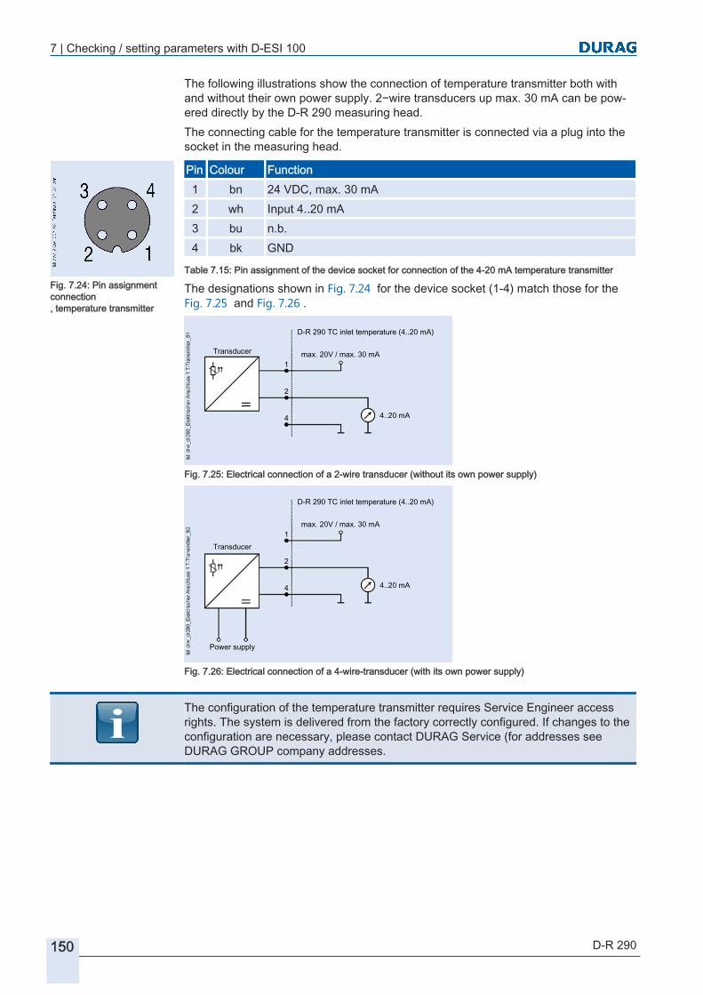
7 | Checking / setting parameters with D‑ESI 100
150 D-R 290
The following illustrations show the connection of temperature transmitter both with and without their own power supply. 2−wire transducers up max. 30 mA can be powered directly by the D‑R 290 measuring head.The connecting cable for the temperature transmitter is connected via a plug into the socket in the measuring head.
Pin Colour Function1 bn 24 VDC, max. 30 mA2 wh Input 4..20 mA3 bu n.b.4 bk GND
Table 7.15: Pin assignment of the device socket for connection of the 4-20 mA temperature transmitter
The designations shown in Fig. 7.24 for the device socket (1-4) match those for the Fig. 7.25 and Fig. 7.26 .
D-R 290 TC inlet temperature (4..20 mA)
Transducer
4..20 mA
max. 20V / max. 30 mA1
2
4
Fig. 7.25: Electrical connection of a 2-wire transducer (without its own power supply)
D-R 290 TC inlet temperature (4..20 mA)
Transducer
4..20 mA
max. 20V / max. 30 mA1
2
4
Power supply
Fig. 7.26: Electrical connection of a 4-wire-transducer (with its own power supply)
The configuration of the temperature transmitter requires Service Engineer access rights. The system is delivered from the factory correctly configured. If changes to the configuration are necessary, please contact DURAG Service (for addresses see DURAG GROUP company addresses.
Fig. 7.24: Pin assignmentconnection , temperature transmitter

D-R 290Dust Concentration and Opacity Monitor of the
Second Generation
88 Maintenance
8.1 Safety
8.2 Maintenance work8.2.1 Visual inspection and cleaning of external parts of the device
8.2.2 Check the purge air unit and the hose connections for leaks and secure fitting.
8.2.3 Checking and changing the filter
8.2.4 Cleaning the outer glass and the zero-point reflector:
8.2.5 Removing deposits from the welded-in pipes
8.2.6 Checking the linearity
8.2.7 Zero point check
8.2.8 Contamination check
8.2.9 Reference point check
8.2.10 Control cycle
8.2.11 Functional test of the fail-safe shutter
8.2.12 Checking the battery in the measuring head
8.3 Error messages / troubleshooting

152 D-R 290

8 | Maintenance
D-R 290 153
MaintenanceThe D‑R 290 is an easily maintained dust concentration measurement system.In this section the necessary maintenance work such as visual checks, cleaning, changing filters etc., are explained, together with some checks and tests.If required, maintenance can also be handled by DURAG GmbH. We will be happy to explain the advantages of a maintenance contract for your company to you. Also the installation and commissioning of the D‑R 290 measuring device can be performed by DURAG. You will find our service addresses and telephone numbers in the appendix on page DURAG GROUP company addresses.
Safety
DANGER High voltage. Risk of fatal injury due to electric shock!Touching live parts poses an immediate risk of fatal injury. Damage to the insulation or to individual components can lead to fatal injury.Therefore:
▶ Permit only skilled electricians to work on electrical equipment.
▶ Before starting work, switch off the power supply and secure it against restoration.
▶ Before removing the casing or guard, check that the devices are deenergised.
▶ Keep moisture away from live components. Moisture can lead to short circuits.
WARNING Danger of burns due to hot surfaces!Contact with hot components can cause serious burns.
▶ Suitable heat-resistant protective gear (such as face mask, safety gloves) must always be worn where any work is undertaken in the vicinity of hot components.
▶ Wherever possible, allow components to cool down to ambient temperature before starting work.
Wherever possible, install or remove components only when the plant is shut down. Before opening the duct access ports:● Make sure that no overpressure is present in the measurement duct.● Make sure that no toxic gases are present in the measurement duct.If it is not possible to shut down the plant, and toxic gases, which may be at high temperature or pressure, are present in the measurement duct:
8
Customer service information
8.1

8 | Maintenance
154 D-R 290
WARNING Health hazard due to hot and/or toxic gases in the duct!When a duct access port (such as a welded-in tube) is opened, pressurised gases may escape.
▶ Always wear suitable protective equipment (such as a face mask, heat-resistant gloves and clothing, protective breathing equipment).
▶ The applicable specifications safety regulations and the operating company working instructions for the plant must be complied with.
WARNING Risk of injury due to crushing and abrasion!Do not insert fingers into the closing area of the fail-safe shutter. Before maintenance work, disconnect terminals 16 and 17 in the DSK AE control electronics. To do this, unplug the connection plug at the measuring head for the fail-safe shutter. (When disconnected, the fail-safe shutter is closed).
WARNING Danger of injury due to insufficient skills!Incorrect use can result in serious personal injury and material damage.Only ever have work performed by suitably qualified specialised personnel! Ensure compliance with the skills and knowledge described in section 2.4.1 Personnel, skills [} 22].
WARNING Risk of injury due to incorrect spare parts! Incorrect or defective spare parts can lead to damage, malfunctions or total failure and may also impair safety.
▶ Only use genuine spare parts supplied by the manufacturer.
▶ Spare parts can be obtained from an authorised agent or directly from the manufacturer.
NOTICE Damage to electronic components due to electrostatic discharge (ESD)Electronic components are becoming ever smaller and more complex. Their susceptibility to damage from electrostatic discharge is increased accordingly. To protect these components, measures must be undertaken to prevent electrostatic discharge during all work performed on the open device (ESD protection).To prevent the human body becoming charged with static electricity, service employees can for example be equipped with a personal earthing system.
Maintenance work
The D‑R 290 is a low maintenance measuring system whose maintenance intervals depend on the installed system and must be specified by the operating company. They depend on:● the type of the medium being measured● the pressure relationships
8.2

8 | Maintenance
D-R 290 155
● the general ambient circumstances (e.g. climatic conditions at the measuring point)It makes sense to start with a short maintenance interval (typically 4 weeks). The maintenance interval can then be increased step by step up to a maximum of 6 months, in accordance with the prevailing conditions.Maintenance should be performed during an inspection of the system being monitored, i.e. this means the system is not in operation.Irrespective of this however, a check should be performed every four weeks. The check is to look for external changes such as deposits, faulty seals, colour changes on the casing, etc. It is also a check that all screw connections, closures and devices are tightly secured.If the measuring system is not maintained or insufficiently maintained, increasing contamination of the lens and filter, if necessary in accordance with the respective instructions for the system, may lead to the failure of the measuring head and possible damage to it.
Table of maintenance work (suggestion)
K* Activity Who Whena Visual inspection and cleaning of external parts of the device Operating personnel** every four weeksa Checking the closures and screw connections Operating personnel** every four weeksa Check the purge air unit and the hose connections for leaks
and secure fittingOperating personnel** every four weeks
b Remove deposits on and within the welded-in pipe Operating personnel** every four weeksb Purge air blower:
Checking the filter Changing the filter(see also Checking / changing the filter)
Specialised staff**every four weekstypically every3 months
b Cleaning the purge air hoses Specialised staff** Typically every3 months
b Measuring head:Checking the contamination value (see --- FEHLENDER LINK ---),if necessary cleaning the device glasses
Specialised staff** every four weeks
b Check the performance LED alignment Specialised staff** Typically every3 months
a Check the measured values for contamination, zero point and reference point
Operating personnel** every four weeks
b Linearity check (see Checking the linearity) Specialised staff** 1/year* K ≘ Category - ** Definition see section 2.4 Personnel [} 22]
Table 8.1: Suggestion for checking and maintenance work
Category for maintenance workWork of category "a" can be performed whilst the plant is in operation (the work instructions are created by the operating company). Work of category "b" requires the purge air to be switched off.
When performing any maintenance work of category "b", ensure that:The purge air is necessary for protection of the component units. The purge air shields components from hot and/or aggressive gases. Loss of the purge air supply even for a (very) short time can lead to malfunctions, damage or total write-off of the measuring head.

8 | Maintenance
156 D-R 290
In the event of over-pressure in the measurement duct, the gas can also pass through the purge air hose to the fan and air filter, and damage those system parts also.
The measuring head and reflector will be damaged if the purge air supply failsIf the purge air supply is not running, the measuring head and reflector within the duct will be irreversibly damaged within a short time due to excessive heat and dust.
▶ It is absolutely essential that the measuring head and reflector are removed from the measurement duct before the purge air is switched off!
▶ Under no circumstances allow the measuring head and reflector to remain in the measurement duct if the purge air supply is not running.
▶ Ensure a reliable supply of purge air, even when the system is stopped.
Also see about this2 Contamination check [} 161]
Visual inspection and cleaning of external parts of the device
In accordance with the maintenance intervals specified by the operator the dust concentration and opacity monitoring system is initially subject to a regular visual check. The check is to look for external changes such as corrosion, faulty seals, colour changes on the housing, etc. There is also a check that all screw connections, closures and devices are tightly secured.Use oil-free compressed air or a soft lint-free cloth, moistened with water and Isopropanol [} 195] if necessary, to remove any deposits.
Check the purge air unit and the hose connections for leaks and secure fitting.
Check the purge air unit, including the purge air hoses, for damage.Check the hose connections for leak-tightness and secure fitting.
Checking and changing the filter
The filter cartridge can be cleaned several times before it has to be replaced. The maintenance intervals for the filters depend on the quality of the intake air.1. System is out of operation, otherwise close the fail-safe shutter.2. Open the filter housing lock. Check the purge air filter at the purge air blower3. If there is loose dirt in the housing: Remove the filter cartridge.
Clean the filter housing (and the filter if required).4. Insert a filter cartridge. When closing the filter housing make sure that the interlock
engages.5. Switch off the power to the purge air unit (blower).6. Reconnect the power supply to the purge air unit.7. If necessary check that the fail-safe shutter opens again.
8.2.1
8.2.2
8.2.3
Fig. 8.1: Purge air filter

8 | Maintenance
D-R 290 157
Cleaning the outer glass and the zero-point reflector:
If the device is indicating a contamination value less than approx. 2%, in general no cleaning work is necessary.
Scratched outer glassDuring any cleaning operation there is a risk of scratching the outer glass in the measuring head. For this reason always take special care when cleaning the optical surfaces.First blow then off with oil-free compressed air to remove any abrasive particles. If necessary then carefully clean them off with a soft non-linting cloth, wetted as necessary with water and alcohol.
To prevent displacement of the zero point reflector by an automatic contamination measurement whilst work is being performed on the screws, first bring the device into zero point measurement mode:
Setting path:
Device (D‑R 290 ) > > Functions > Maintenance / Service Functions > Maintenance Functions > Start zero point test
A Securing the zero point reflector with hexagon socket-head screws
B Face to be cleaned of the zero point reflector
C Face to be cleaned of the outer glass
Fig. 8.2: Optical surfaces
8.2.4
Preparation:
Measuring unit:

8 | Maintenance
158 D-R 290
1. Open the four quick-release clamps and swing down the measuring unit.2. For better handling it is recommended to dismantle the zero point reflector from the
drive shaft.3. To do this, loosen the hexagon socket-head screws (A, see illustration) and care
fully pull off the zero point reflector.4. Clean the outer glass (C, see illustration) and zero point reflector (on face B, see
illustration).5. After cleaning it, re-install the zero point reflector in its original position on the drive
axis.6. Swing the measuring unit shut and close the four quick-release clamps.1. Open the four quick-release clamps and swing down the reflector.2. Carefully clean the outer glass (directly in front of / on the reflector) so that no
smears are present.3. Swing the measuring unit shut and close the four quick-release clamps.4. Swing the reflector shut and close the four quick-release clamps.Terminate the zero point measurement:
Setting path:
device (D‑R 290 ) > > Functions > Maintenances / ServiceFunctions > Maintenance Functions > Stop zero point test
Removing deposits from the welded-in pipes
Remove any deposits in (and also on) the welded-in pipes.Never touch parts which could be hot without temperature-resistant equipment or protective gloves. Depending on the characteristics, pressure and temperature of the gases in the duct, it may be that the inside of the welded-in pipes can be cleaned only when the plant is shut down. Before removing the measuring head and reflector (including where necessary the fail-safe shutters), make sure that none of the gases present constitute a health hazard.Dirt can be removed using oil-free compressed air, a brush or cloth and cleaning agents that dry without leaving any residue (e.g. dishwashing liquid) .Do not under any circumstances use solvents that attack aluminium.
Checking the linearity
The purpose of the linearity check is to check the functional performance of the device in accordance with European and international standards.Linearity filters according to US EPA and EN 15267 can be ordered from DURAG as special accessories.
Open the housing:
First pull the plugthen open the door
Reflector unit:
Finally:
8.2.5
8.2.6
Fig. 8.3: EPA-Test filter

8 | Maintenance
D-R 290 159
1. In order to perform a linearity test, open the 4 quick-release clamps on the measuring head and swing the measuring head aside.
Fig. 8.4: Insert the test filter into the device
2. The linearity measurement with the test filters can then be performed. You can check the filters by plugging them into the filter holder in front of the outer glass on the measuring head (see illustration above).
3. The linearity measurement is started from the D−ESI 100 [} 195] or D-ISC 100 [} 195].
Setting path:
Device (D‑R 290 ) > > Functions > D‑R 290 Linearity test > Start linearity test
The output of the measured values is performed directly in the function menu:
Setting path:
Device (D‑R 290 ) > > Functions > D‑R 290 Linearity test > Linearity test measured value [% OP SP]
The type of output of the linearity values on the four measurement channels can be set by the parameter
Setting path:
Device (D‑R 290 ) > > Functions > D‑R 290 Linearity test > Scaling the linearity values
:● If this parameter is set to "0" the device measures in normal mode, i.e. the meas
ured value from the linearity test is output on all channels. Depending on the 7.5.2 Type code [} 127] that is used, opacity, transmission, optical density etc. are also output.
● If this parameter is set to "1" the opacity value in [% opacity single path] in each channel is scaled according to the respective signal range.
Open the housing:
First pull the plugthen open the door

8 | Maintenance
160 D-R 290
Example 1 (linearity test without scaling)1. The linearity measurement is started and a test filter with an opacity of approx.
15.4% is inserted.2. The scaling is set to 0.3. The measured values of the device are assigned as shown in Fig. 8.5 to:
∙ Channel 1 Optical density (double path) 0.145∙ Channel 2 Opacity (PLCF = 1) 15.4%∙ Channel 3 Opacity SP 15.4%∙ Channel 4 Measured dust value (factor a=0, b =
200)29.1 mg/m3
∙ Directly measured value: 15.4% OP SP
Fig. 8.5: Example of a linearity test without scaling
Example 2 (linearity test with scaling)The linearity measurement is started and a test filter with an opacity of approx. 15.4% is inserted.The scaling is set to 1.The channels are set to the following signal ranges (see also section 7.5.3.5 Signal range [} 133] and 7.5.2.1 Available type codes for the D-R 290 [} 128]):
∙ Channel 1 Optical density (double path) 0 to 2∙ Channel 2 Opacity (PLCF = 1) 0 to 20 % OP∙ Channel 3 Opacity SP 0 to 100 % OP SP∙ Channel 4 Measured dust value 0 to 200 mg/m3
The measured values of the device are assigned as shown in Fig. 8.6 to:
∙ Channel 1 Optical density (double path) 0.309 (~15.4% of 2)∙ Channel 2 Opacity (PLCF = 1) 3.1 (~15.4% of 20)∙ Channel 3 Opacity SP 15.4 (~15.4% of 100)∙ Channel 4 Measured dust value 30.9 (~15.4% of 200)∙ Directly measured value: 15.4% OP SP

8 | Maintenance
D-R 290 161
Fig. 8.6: Example of a linearity test with scaling
Zero point check
The zero point check can be started and stopped by:
Setting path:
Device (D‑R 290 ) > > Functions > Maintenance / Service Functions > Start zero point check
Device (D‑R 290 ) > > Functions > Maintenance / Service Functions > Stop zero point check
During the zero point check the device measures the received intensity with the zero point reflector swung into position, and compares it with the reference value. The output from the measuring channels is dependent in every case on the settings for the channel (see section 7.5.3.6 Settings [} 133]).Direct output of the opacity measured during the current measurement and during the last zero point measurement can be found under:
Setting path:
Device (D‑R 290 ) > > Specific parameters >D‑R 290 Measured values > Zero point value [% OP SP]
Contamination check
The D−R 290 automatically performs a contamination measurement once an hour.The contamination measurement can also be performed manually via:
Setting path:
Device (D‑R 290 ) > > Functions > Maintenances / Service Functions > Start contamination check
Device (D‑R 290 ) > > Functions > Maintenance / Service Functions > Stop contamination check
8.2.7
8.2.8

8 | Maintenance
162 D-R 290
starts and stops the check. During the contamination check the device measures the intensity with the zero point reflector swung into position, and compares it with the factory calibration value. The output from the measuring channels is dependent in every case on the settings for the channel (see section 7.5.3.6 Settings [} 133]).Direct output of the contamination result measured during the current measurement and during the last contamination measurement can be found under:
Setting path:
Device (D‑R 290 ) > > Specific parameters > D‑R 290 Measured values > contamination [%]
Reference point check
The reference point check can be started and stopped manually via:
Setting path:
Device (D‑R 290 ) > > Functions > Maintenance / Service Functions > Start Reference point check
Device (D‑R 290 ) > > Functions > Maintenance / Service Functions > Stop Reference point check
During the reference point check the device measures the intensity with the zero point reflector swung into position and mesh filter swung into position, and compares it with the factory reference value. The output from the measuring channels is dependent in every case on the settings for the channel (see section 7.5.3.6 Settings [} 133]).Direct output of the opacity measured during the current measurement and during the last reference value measurement can be found under:
Setting path:
Device (D‑R 290 ) > > Specific parameters > D‑R 290 Measured values > Reference point value [% OP SP]
Control cycle
The automatic control cycle is performed automatically; interval and duration of the individual measurements can be configured on the maintenance settings (see section 7.7.2 Control cycle step duration and control cycle interval [} 140]).During the control cycle the following tests are performed successively:● contamination check● zero point check● reference point checkIn addition to the automatic performance, the control cycle can be started and stopped manually by:
Setting path:
Device (D‑R 290 ) > > Functions > Maintenance / Service Functions > Start automatic control cycle
Device (D‑R 290 ) > > Functions > Maintenance / Service Functions > Stop automatic control cycle
8.2.9
Fig. 8.7: Turntable plate
8.2.10
8 | Maintenance
D-R 290 163
The control cycle, irrespective of whether it is started automatically or manually, always ends automatically once the cycle has been completed.All other functions (zero point check, reference point check, contamination check, linearity check) remain active until either they are terminated or another function is started.
Functional test of the fail-safe shutter
Maintenance and the functional test on the fail-safe shutter should be carried out at the maintenance interval for the measuring instrument, depending on the dust or soot content of the measuring gases.For checking for deposits in the guide slot of the fail-safe shutter, and for removal of those deposits the protective device including the measuring head or reflector must be dismantled.To avoid unnecessary downtime this can be scheduled to be done in the course of plant inspection.
WARNING Risk of injury due to crushing and abrasion!Do not insert fingers into the closing area of the fail-safe shutter. Before maintenance work, disconnect terminals 16 and 17 in the DSK AE control electronics. To do this, unplug the connection plug at the measuring head for the fail-safe shutter. (When disconnected, the fail-safe shutter is closed).
1. Where disassembly of the device from the measuring site is necessary, undo the connections:∙ between the measuring head and control unit∙ between the fail-safe shutters and control device for the fail-safe shutters (including the connecting cables to the measuring head).
2. By undoing the quick-release clamps, release the measuring head or reflector from the purge air flange.
3. If necessary, disconnect the measuring head or reflector as from the purge air supply.
4. Pull the rubber sleeve from the space in the D‑SK 290 MA fail-safe shutter and the purge air flange over the purge air flange.
5. Undo the self-locking nuts and take the spherical washers off the threaded studs.6. Detach the purge air flange for the measuring head or reflector from the threaded
bolts.7. Take the disc springs off the threaded bolts on the flange tube.8. Carefully release the D‑SK 290 MA fail-safe shutter from the welded-in flanged
tube, and remove it. Make sure that the flat seal in front of the flange tube is not damaged. Damaged seals must be replaced immediately.
9. Checking for deposits in the guide slot of the fail-safe shutter, and remove them if necessary. Dirt can be removed using oil-free compressed air, a brush or cloth and cleaning agents that dry without leaving any residue (e.g. dishwashing liquid). Do not under any circumstances use solvents that attack aluminium.
10. Reinstall the measuring head or reflector, and reconnect the purge air supply.● Test the fail-safe shutter with the test function:
8.2.11
Checking fordeposits
Testing the fail-safe shutter

8 | Maintenance
164 D-R 290
Setting path:
Device (D‑R 290 ) > > Functions > D‑R 290 Service Functions > Test the fail-safe shutter 1or
Device (D‑R 290 ) > > Functions > D‑R 290 Service Functions > Test the fail-safe shutter 2
The fail-safe shutter is operating correctly if during the test the shutter closes once and opens again.At intervals of approx. 6 months the operational status of the supercaps should also be tested:● Check LED 5 on the control electronics (figure on the left – L5). The LED will light up if the supercaps charging status is OK.A possible cause of any malfunction is a defect in the charging electronics or a defective supercap.In such cases, check the charging electronics (printed circuit board D-SK AE no.30 mains adaptor) and replace them if they are defective.
Checking the battery in the measuring head
The battery in the measuring head buffers the power supply for the internal clock within the measuring head. This clock provides system messages with timestamp.After a long time in storage without a power supply this battery can become discharged. Frequent occurrence of the warning [81] (see [} 168]) "Clock not set" may also indicate a discharged battery.To change the battery, proceed as follows:
Opening the housing1. Open the four quick-release clamps and swing down the measuring unit.
2. The 6 screws for the housing cover are accessible internally. Undo them in the sequence specified at the bottom left.Before undoing the last screw (6) grasp the handle of the housing cover with one hand, so that the housing cover is supported by the lower arm.
3. Put the housing cover aside.
Checking the supercaps
Fig. 8.8: LED 5
8.2.12
Open the housing:
First pull the plugthen open the door
Fig. 8.9: Attachment screws for thehousing cover
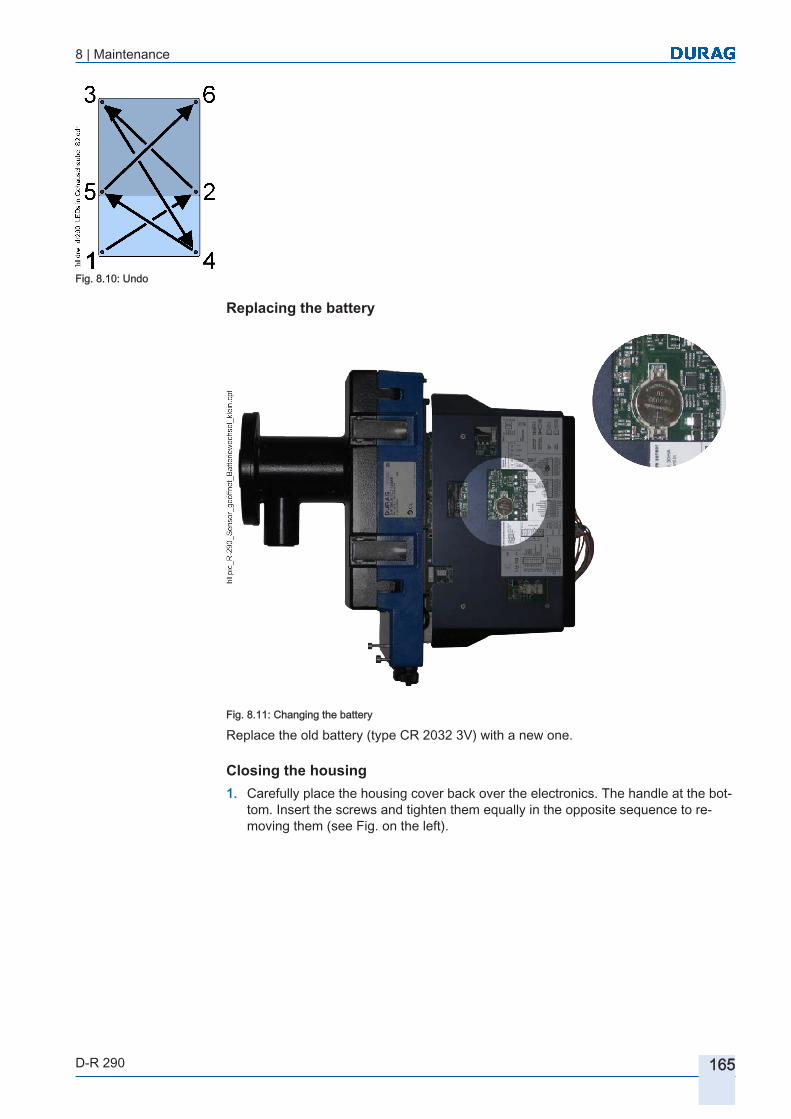
8 | Maintenance
D-R 290 165
Replacing the battery
Fig. 8.11: Changing the battery
Replace the old battery (type CR 2032 3V) with a new one.
Closing the housing1. Carefully place the housing cover back over the electronics. The handle at the bot
tom. Insert the screws and tighten them equally in the opposite sequence to removing them (see Fig. on the left).
Fig. 8.10: Undo
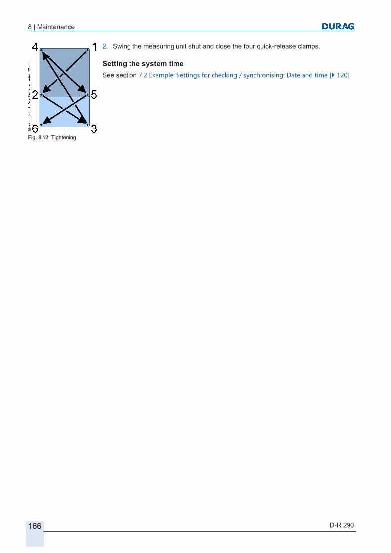
8 | Maintenance
166 D-R 290
2. Swing the measuring unit shut and close the four quick-release clamps.
Setting the system timeSee section 7.2 Example: Settings for checking / synchronising: Date and time [} 120]
Fig. 8.12: Tightening

8 | Maintenance
D-R 290 167
Error messages / troubleshooting
Sequ. no.
Message Cause;(●) available actions by whom
[001] System start (switched on) The system has been switched on.● No action necessary
[002] System start (external reset) A system start was triggered by the internal reset logic.● No action necessary
[003] System start (watchdog reset) A system start was triggered by the internal watchdog timer. A deliberate soft reset will also trigger this message!● If this error occurs frequently, there is a fault in
the electronics, and the measuring head must be sent in to the Service Dept for repair.
Manufacturer(send the device back)
[004] System start (BOD reset) A system start has been triggered due to detection of an undervoltage.● Check the 24V power supply
Specialisedelectrician
[005] System start (with default jumper)
The measuring head has been restarted by placing the default jumper on to X14● No action necessary
[006] Zero point measurement is being performed
The system is performing zero point measurement● No action necessary
[007] Reference point measurement is being performed
The system is performing reference point measurement● No action necessary
[008] Contamination measurement is being performed
The system is performing contamination measurement● No action necessary
[009] Parameter change saved Changed parameter have been saved● No action necessary
[010] Logbook was reset The records logbook has been cleared down● No action necessary
[011] Message counter was reset The message counter has been reset● No action necessary
[012] Device starting The device is in start mode and not yet ready to operate. The duration of the wait until readiness to operate is approx. 20 sec● No action necessary
[013] Linearity test being performed The system is in linearity measurement mode➔ No action necessary
[014] LED comparison is being performed
The system is performing an LED comparison (initiated by a Service Engineer)● No action necessary
[015] Initial contamination measurement being performed
The system is performing an initial contamination measurement (initiated by a Service Engineer)● No action necessary
8.3

8 | Maintenance
168 D-R 290
Sequ. no.
Message Cause;(●) available actions by whom
[016] Initial LED comparison being performed
The system is performing an initial LED comparison (initiated by a Service Engineer)● No action necessary
[017] Initial reference measurement being performed
The system is performing an initial reference measurement (initiated by a Service Engineer)● No action necessary
[018] Calibration of dust-free measuring path being performed
The system is in dust-free measuring path calibration mode● No action necessary
[019] Offset measurement being performed
The system is performing an offset measurement (initiated by a Service Engineer)● No action necessary
[020] Device is performing a fail-safe shutter test [020]
The system is testing the fail-safe shutter 1● No action necessary
[021] Device is performing a fail-safe shutter test
The system is testing the fail-safe shutter 2● No action necessary
[022] Simulation / function test being performed
System is in simulation mode● No action necessary
[023] Device is in maintenance mode
System is in maintenance mode● No action necessary
[024] Device outputting PLCF The device is outputting the scaled stack factor (PLCF).(for devices according to the US EPA)● No action necessary
Table 8.2: List of messages for D‑R 290
Sequ. no.
Warning Cause;(●) available actions by whom
[064] Measured value 1:Upper limit value 1 active
The upper limit value 1 of measurement channel 1 has been exceeded
[065] Measured value 1:Lower limit value 1 active
The lower limit value 1 of measurement channel 1 has been undershot.
[066] Measured value 1:Upper limit value 2 active
The upper limit value 2 of measurement channel 1 has been exceeded
[067] Measured value 1:Lower limit value 2 active
The lower limit value 2 of measurement channel 1 has been undershot.
[068] Measured value 2:Upper limit value 1 active
The upper limit value 1 of measurement channel 2 has been exceeded
[069] Measured value 2:Lower limit value 1 active
The lower limit value 1 of measurement channel 2 has been undershot.
[070] Measured value 2:Upper limit value 2 active
The upper limit value 2 of measurement channel 2 has been exceeded
[071] Measured value 2:Lower limit value 2 active
The lower limit value 2 of measurement channel 2 has been undershot.
[072] Measured value 3:Upper limit value 1 active
The upper limit value 1 of measurement channel 3 has been exceeded
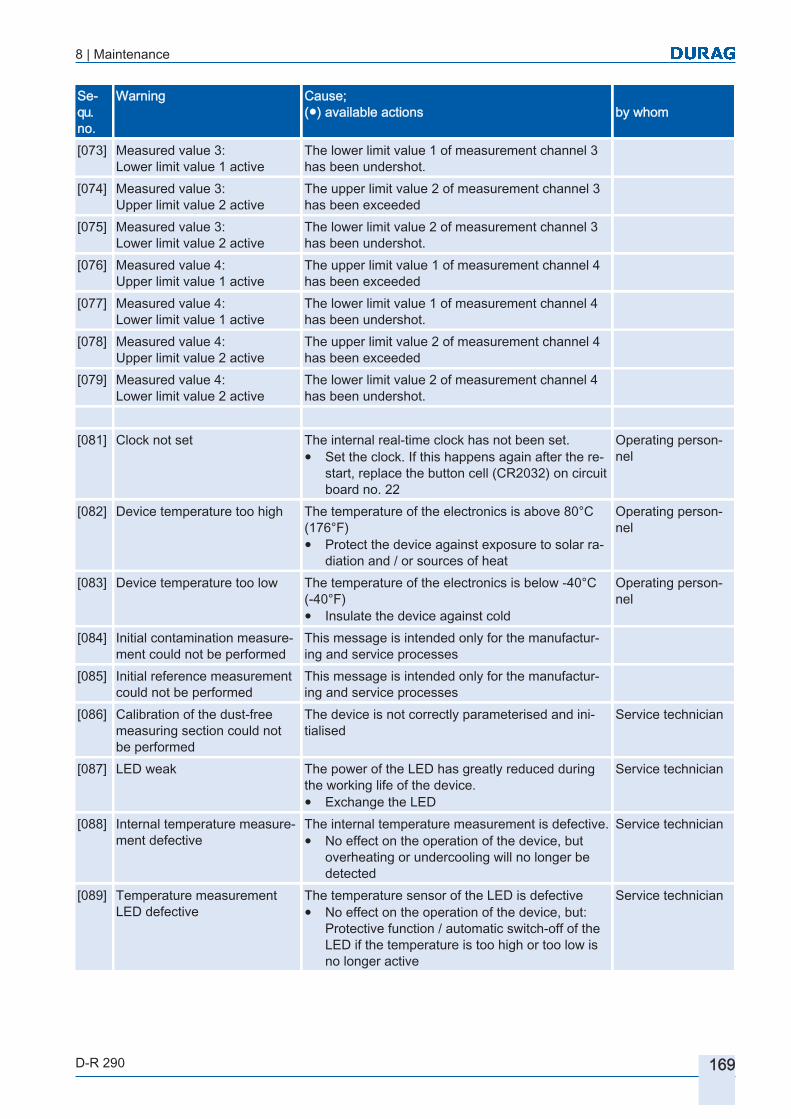
8 | Maintenance
D-R 290 169
Sequ. no.
Warning Cause;(●) available actions by whom
[073] Measured value 3:Lower limit value 1 active
The lower limit value 1 of measurement channel 3 has been undershot.
[074] Measured value 3:Upper limit value 2 active
The upper limit value 2 of measurement channel 3 has been exceeded
[075] Measured value 3:Lower limit value 2 active
The lower limit value 2 of measurement channel 3 has been undershot.
[076] Measured value 4:Upper limit value 1 active
The upper limit value 1 of measurement channel 4 has been exceeded
[077] Measured value 4:Lower limit value 1 active
The lower limit value 1 of measurement channel 4 has been undershot.
[078] Measured value 4:Upper limit value 2 active
The upper limit value 2 of measurement channel 4 has been exceeded
[079] Measured value 4:Lower limit value 2 active
The lower limit value 2 of measurement channel 4 has been undershot.
[081] Clock not set The internal real-time clock has not been set.
● Set the clock. If this happens again after the restart, replace the button cell (CR2032) on circuit board no. 22
Operating personnel
[082] Device temperature too high The temperature of the electronics is above 80°C (176°F)● Protect the device against exposure to solar ra
diation and / or sources of heat
Operating personnel
[083] Device temperature too low The temperature of the electronics is below -40°C (-40°F)● Insulate the device against cold
Operating personnel
[084] Initial contamination measurement could not be performed
This message is intended only for the manufacturing and service processes
[085] Initial reference measurement could not be performed
This message is intended only for the manufacturing and service processes
[086] Calibration of the dust-free measuring section could not be performed
The device is not correctly parameterised and initialised
Service technician
[087] LED weak The power of the LED has greatly reduced during the working life of the device.● Exchange the LED
Service technician
[088] Internal temperature measurement defective
The internal temperature measurement is defective.● No effect on the operation of the device, but
overheating or undercooling will no longer be detected
Service technician
[089] Temperature measurement LED defective
The temperature sensor of the LED is defective● No effect on the operation of the device, but:
Protective function / automatic switch-off of the LED if the temperature is too high or too low is no longer active
Service technician

8 | Maintenance
170 D-R 290
Sequ. no.
Warning Cause;(●) available actions by whom
[090] Temperature measurement of the stepper motor is defective
The temperature sensor of the stepper motor is defective● No effect on the operation of the device, but:
Protective function / automatic switch-off of the stepper motors if the temperature is too high or too low is no longer active
Service technician
[091] Warning of contamination The device contamination is higher than the configurable warning threshold● Clean the device plate, zero point reflector and
reflector unit
Specialised personnel
[092] Purge air flow 1 (measuring head) too low
Purge air flow is below the warning threshold. Possible causes: Filter clogged, purge air hose split, parameterisation of the purge air inlet defective.● Measurement function still operates, but a rapid
increase in contamination can be expected. Check the purge air flow / restore the flow or remove the device from the flue stack.
Specialised personnel
[093] Purge air flow 2 (reflector) too low
Purge air flow is below the warning threshold. Possible causes: Filter clogged, purge air hose split, parameterisation of the purge air inlet defective.● Measurement function still operates, but a rapid
increase in contamination can be expected. Check the purge air flow / restore the flow or remove the device from the flue stack.
Specialised personnel
[094] Purge air flow 1 (measuring head) too high
Purge air flow above the warning threshold. If the purge air flow is too high, depending on the flue stack temperature and flue gas velocity there may be an effect on the measured values.● Check the effect of the purge air on the meas
ured values
Specialised personnel
[095] Purge air flow 2 (reflector) too high
Purge air flow above the warning threshold. If the purge air flow is too high, depending on the flue stack temperature and flue gas velocity there may be an effect on the measured values.● Check the effect of the purge air on the meas
ured values
Specialised personnel
[096] LED heating defective No current flowing through the LED heating● Measurement function still operates, but at very
low temperatures (< -30°C/-22°F) a protective shut-down of the LED may occur
Service technician
[097] Stepper motor heating defective
No current flowing through the stepper motor heating● Measurement function still operates, but at very
low temperatures (< -40°C/-40°F) a protective shut-down of the stepper motor may occur
Service technician
[098] Disc heater defective No current flowing through the disc heater● Measurement function still operates, but if tem
peratures fluctuate greatly and at high atmospheric humidity, condensation may occur on the device disc
Service technician
Table 8.3: List of warnings for the D‑R 290

8 | Maintenance
D-R 290 171
Sequ. no.
Simple fault Cause;(●) available actions by whom
[128] System settings invalid The device settings held in the EEPROM are invalid. The device may be operating with invalid parameters.
● Check the device settings and correct them if necessary. After the correction, save the changes!
Specialisedpersonnel
● If the fault persists, the electronics are defective. Service technician[129] Invalid firmware The device firmware may not be operating correct
ly.
● Check the operation of the device and any other messages, reboot the device.
Service technician
● If the fault persists, the electronics are defective.[130] Device not initialised The device is not correctly parameterised, or the
parameterisation has been lost due to a memory defect.
Service technician
[131] Receiver overrun The signal intensity is too high.● Check the beam inlet, comply with the minimum
distance between the reflectors
Specialisedpersonnel
[132] Receiver overrun Electronics fault. Service technician[133] Receiver overrun Electronics fault. Service technician[134] Receiver overrun Electronics fault. Service technician[135] Contamination error The contamination is greater than 10%.
● Clean the device plate, zero point reflector and reflector unit
Specialisedpersonnel
[136] LED undertemperature shut-down
The LED was shut down because the LED temperature was too low.● If the device is started up at a very low tempera
ture, the warming up of the device components can take up to 30 min.
● Check the device temperature andthe current in the heaters
Specialisedpersonnel
[137] LED overtemperature shut-down
The LED was shut down because the LED temperature was too high.● Provide cooling.
Specialisedpersonnel
[138] Stepper motor undertemperature shut-down
The stepper motor was shut down because the stepper motor temperature was too low.● If the device is started up at a very low tempera
ture, the warming up of the device components can take up to 30 min.
● Check the device temperature and the current in the heaters
Specialisedpersonnel
[139] Stepper motor overtemperature shut-down
The stepper motor was shut down because the stepper motor temperature was too high.● Provide cooling.
Specialisedpersonnel

8 | Maintenance
172 D-R 290
Sequ. no.
Simple fault Cause;(●) available actions by whom
[140] Stepper motor error The stepper motor driver has reported a fault.● Check the stepper motors for correct operation,
check that plug X4 is securely seated● If the error occurs repeatedly or over an exten
ded period, the electronics may be defective
Specialisedpersonnel
[141] Stepper motor error The stepper motor driver has reported a fault. ➔ Check the stepper motors for correct operation, check that plug X4 is securely seated● If the error occurs repeatedly or over an exten
ded period, the electronics may be defective
Specialisedpersonnel
[142] Purge air flow 1 (measuring head) too low
Purge air flow is below the fault threshold. Possible causes: Blower defective, filter clogged, purge air hose split, parameterisation of the purge air inlet defective.● It can be expected that the measurement func
tion may be impaired by dust in the welded-in pipes, by a rapid increase in contamination or damage to the device due to high temperatures. Check the purge air flow / restore the flow or remove the device from the flue stack.
Specialisedpersonnel
[143] Purge air flow 2 (reflector) too low
Purge air flow is below the fault threshold. Possible causes: Blower defective, filter clogged, purge air hose split, parameterisation of the purge air inlet defective.● It can be expected that the measurement func
tion may be impaired by dust in the welded-in pipes, by a rapid increase in contamination or damage to the device due to high temperatures. Check the purge air flow / restore the flow or remove the device from the flue stack.
Specialisedpersonnel
[144] Fail-safe shutter 1 (measuring head) closed
The fail-safe shutter at the measuring head is closed. This means that valid measurement values are no longer being reported.● Check the reason for closure of the shutter (has
the purge air failed?)
Operatingpersonnel
[145] Fail-safe shutter 2 (reflector) closed
The fail-safe shutter at the reflector is closed. This means that valid measurement values are no longer being reported.● Check the reason for closure of the shutter (has
the purge air failed?)
Operatingpersonnel
Table 8.4: List of simple faults for the D‑R 290
Sequ. no.
Critical fault Cause;(●) available actions by whom
[192] Hardware fault The electronic hardware of the device has a serious internal fault.● Exchange the electronics (No. 22)
Service technician
[193] Hardware fault The electronic hardware of the device has a serious internal fault.● Exchange the electronics (No. 22)
Service technician

8 | Maintenance
D-R 290 173
Sequ. no.
Critical fault Cause;(●) available actions by whom
[194] Hardware fault The electronic hardware of the device has a serious internal fault.● Exchange the electronics (No. 22)
Service technician
[195] Zero point reflector positioning error
The zero point reflector could not find the light barrier.
● Check the operation of the stepper motors Operatingpersonnel
● Possibly exchange the light barrier Service technician[196] Turntable position error The turntable could not find the light barrier.
● Check the operation of the stepper motors Operatingpersonnel
● Possibly exchange the light barrier Service technician[197] LED current too low No current through the LED, or very little current
● Check the plug / contact of the LED connecting cable
Operatingpersonnel
● LED possibly defective: Exchange the LED Service technician[198] LED current too high Current through the LED is too high
● LED possibly defective: Exchange the LED● Error in activating the LED, electronics (no. 22)
Service technician
[199] Fault fail-safe shutter 1(measuring head)
Switch contact fault at the fail-safe shutter protecting the measuring head● Check the connections for the fail-safe shutter
protecting the measuring head, and check the control device
Specialisedpersonnel
[200] Fault fail-safe shutter 2(reflector)
Switch contact fault at the fail-safe shutter protecting the reflector● Check the connections for the fail-safe shutter
protecting the measuring head, and check the control device
Specialisedpersonnel
[201] Fail-safe shutter 1 blocked(measuring head)
Fail-safe shutter protecting the measuring head does not open or close within 3 min.● If the supercaps for starting the device were
completely discharged, restart the device● Check the operation of the fail-safe shutter● Check the connections for the fail-safe shutter
protecting the measuring head, and check the control device
Specialisedpersonnel
[202] Fail-safe shutter 2 blocked (reflector)
Fail-safe shutter protecting the reflector does not open or close within 3 min.● If the supercaps for starting the device were
completely discharged, restart the device● Check the operation of the fail-safe shutter● Check the connections for the fail-safe shutter
protecting the measuring head, and check the control device
Specialisedpersonnel
Table 8.5: List of critical faults for the D‑R 290

8 | Maintenance
174 D-R 290

D-R 290Dust Concentration and Opacity Monitor of the
Second Generation
9 Appendix
Appendix9.1 Measurement point questionnaire
9.2 D-R 290 technical data 9.2.1 D-R 290 application data
9.2.2 D-R 290 measuring head and reflector
9.2.3 D-SK AE control electronics protective device
9.2.4 D-SK 290 MA fail-safe shutter protective device
9.2.5 D-TB 100 supply unit (terminal box)
9.2.6 D-BL XXX purge air unit
9.3 Dimensional diagrams9.3.1 Dimensional diagram of the measuring head/reflector
9.3.2 Dimensional diagram of the measuring head/reflector with fail-safe shutter
9.3.3 Dimensional diagram of the welded-in pipe with adjustment flange
9.3.4 Dimensional diagram of the control electronics D-SK AE
9.3.5 Dimensional diagram fail-safe shutter D-SK MA
9.3.6 Dimensional diagram supply unit (terminal box) D-TB 100
9.3.7 Dimensional diagram purge air unit D-BL
9.3.8 Dimensional diagram (optional) weather protection covers

176 D-R 290

9 | Appendix
D-R 290 177
Appendix
Measurement point questionnaire
Fig. 9.1: Measurement point questionnaire 1
9
9.1

9 | Appendix
178 D-R 290
Fig. 9.2: Measurement point questionnaire 2

9 | Appendix
D-R 290 179
D-R 290 technical data
Comments:* Variants** others on request▷ We reserve the right to make technical changes!
D-R 290 application data
Sample gas type Air, flue gas, non-combustible process gasSample gas temperature above dewpoint,
-25…250°C standard-25…1000°C option
-13…482°F-13…1832°F
Inner duct pressure -50…+20 hPaSample gas relative humidity 0...95 % non-condensingStack / duck inner diameter 1…18 m, dependent on the flange diameter and reflector type
Table 9.1: Technical data, D-R 290 application data
D-R 290 measuring head and reflector
Physical measuring value Optical density / extinctionopacity
Derived measuring values Transmission, opacity (SP), dust concentration in mg/m3, mg/Nm3 after gravimetric calibration, extinction coefficient, visibiltiy
Measuring range, opacity 0…20 % … 0…100 %Output range opacity Freely configurable within the measuring rangeMeasuring range, extinction 0…0.1 … 0…2Output range extinction Freely configurable within the measuring rangeMeasuring range dust concentration 0…80 mg/m3 … 0…4000 mg/m3 (dependent on the calibration)Output range dust concentration Freely configurable within the measuring rangeLowest detection limit 0.75 % for measuring range 0…0.1 extinctionCombined standard uncertainty to QAL1 [} 196], DIN EN 14181
1.8 % based on the certified measuring range end value 15 mg/m3
Light source, spectral range 450… 680 nm, SWBD LED whiteProcess connection Adjustment flange, pitch circle diameter 100 mm
Adjustment flange, pitch circle diameter 150 mmDigital interfaces RS 485 Modbus RTU, bi-directional communication,
mini-USB (service)Analogue outputs 1x 4-20 mA, 400 Ohm, isolated, assignment parameterisableDigital outputs 2x contact NC/NO, max. load 60 V / 30 V~ / 0,5 A
Function parameterisable, typically: Maintenance, failureOperating voltage 24 V , 0.5 A
9.2
9.2.1
9.2.2

9 | Appendix
180 D-R 290
Overvoltage category CAT IIAmbient temperature -40...+60°C (-40...+140°F)IP Code (IEC 60529) IP65EX zone Option: Ex II 3G Ex pz II T4, Ex II 3D Ex pz II T4Installation altitude ≤ 2000 m above mslDimensions (HxWxD): Approx. 370 x 190 x 400 mmWeight Approx. 10 kgMaterial Aluminium, painted blue RAL 5017 Service software D−ESI 100, requires a PC with Windows XP®, Windows 7®
OS or Windows 8® OS
Table 9.2: Technical data, D-R 290 measuring head
Process connection Adjustment flange, pitch circle diameter 100 mmAdjustment flange, pitch circle diameter 150 mm
Ambient temperature -40...+60°C (-40...+140°F)IP Code (IEC 60529) IP65Installation altitude ≤ 2000 m above mslDimensions (HxWxD): Approx. 370 x 190 x 270 mmWeight Approx. 7 kgMaterial Aluminium, painted blue RAL 5017
Table 9.3: Technical data, D-R 290 reflector
D-SK AE control electronics protective device
Digital outputs 1 contact fail-safe shutter “CLOSED“,1 contact fail-safe shutter “OPEN“,1 changeover contact “Purge air“ available / failedcontact rating 48 V , 0.5 A
Power supply 25-264 V~ 47-440 Hz, 10 VAOvervoltage category CAT IIMotor drive 24V Ambient temperature -20…+50°C (-4…+122°F)IP Code (IEC 60529) IP65Installation altitude ≤ 2000 m above mslDimensions (HxWxD): Approx. 250 x 200 x 100 mmWeight Approx. 3.5 kgMaterial Aluminium, painted blue RAL 5017
Table 9.4: Technical data, D-SK AE control electronics protective device
D-SK 290 MA fail-safe shutter protective device
Motor drive Rotary drive, 24 V with built-in motor protection switchTorque 8 Nm
9.2.3
9.2.4

9 | Appendix
D-R 290 181
OPEN/CLOSE time Approx. 2 secondsAmbient temperature -20…+120°C (-4…+248°F)IP Code (IEC 60529) IP65Installation altitude ≤ 2000 m above mslDimensions (HxWxD): Approx. 250 x 200 x 150 mmWeight Approx. 4.5 kgMaterial Shut-off shutter: Stainless steel 1.4571
housing: Aluminium, painted
Table 9.5: Technical data, D-SK 290 MA fail-safe shutter protective device
D-TB 100 supply unit (terminal box)
Operating voltage 90…264 V~, 48…62 Hz)Output voltage 24 V Overvoltage category CAT IIAmbient temperature -25…+55°C (-13…+131°F)IP Code (IEC 60529) IP65 (NEMA 4, 4X)Installation altitude ≤ 2000 m above mslDimensions (HxWxD): approx. 160 x 230 x 105 mm or 180 x 230 x 105 mmTests for Flammability of Plastic Materials for Parts in Devices and Applications
to IEC/DIN EN 60695-11 -10 and -20, UL 94-V0
Weight Approx. 1.5 kgMaterial Polycarbonate, light grey RAL 7035
Table 9.6: Technical data, D-TB 100 supply unit (terminal box)
D-BL XXX purge air unit
Power supply 115/230 V~, 50/60 Hz *0,4 kW /0,5 kW
Overvoltage category CAT IIPurge air quantity approx. 80/90 m3/hIP Code (IEC 60529) IP55Installation altitude ≤ 2000 m above mslSound pressure level ≤ 63 dB(A)Dimensions (HxWxD): Approx. 350 x 550 x 500 mmWeight Approx. 12 kg* other voltages and frequencies available on request The purge air unit is supplied with 10 m of purge air hose Ø 40 mm with a permissible temperature range – 25 to + 85°C (-13…185°F)..
Table 9.7: Technical data, D-BL xxx purge air unit
9.2.5
9.2.6

9 | Appendix
182 D-R 290
Dimensional diagrams
Dimensional diagram of the measuring head/reflector
Fig. 9.3: Dimensional diagram of the measuring head/reflector
D1, D4 see Table 9.8
9.3
9.3.1

9 | Appendix
D-R 290 183
1 Adjustment flanges aligned to each other within ± 1°2 Duct wall 3 Welded-in pipe with adjustment
flange4 Red dot 6 Rubber sleeve7 12 disc springs * 8 1 spherical washer *9 1 self-locking nut * 10a Measuring head (MK)
10b Reflector (R) * per threaded studFig. 9.4: Installation example on a horizontal duct

9 | Appendix
184 D-R 290
Dimensional diagram of the measuring head/reflector with fail-safe shutter
Fig. 9.5: Dimensional diagram of the measuring head/reflector with fail-safe shutter
D1 see Table 9.8
9.3.2

9 | Appendix
D-R 290 185
1 Adjustment flanges aligned to each other within ± 1°2 Duct wall 3 Welded-in pipe with adjustment
flange4 Red dot 6 Rubber sleeve7 12 disc springs * 8 1 spherical washer *9 1 self-locking nut * 10a Measuring head (MK)
10b Reflector (R) * per threaded studFig. 9.6: Installation example on a horizontal duct
Dimensional diagram of the welded-in pipe with adjustment flange
Fig. 9.7: Dimensional diagram D−R 290 standard welded-in pipe with adjustment flange (↘= red dot)
D1 Pitch circle diameter Ø
[mm]
D2 Tube outside Ø
[mm]
D3 Tube inside Ø
[mm]
D4 Flangeoutside Ø
[mm]
L1 max. permissible
length[mm]
L2 Stud length[mm]
100 65 59 130 200 ~73100 89 83 130 600 ~73150 89 83 190 600 ~80150 114.3 107.1 190 1000 ~80
Table 9.8: Welded-in pipe lengths
9.3.3

9 | Appendix
186 D-R 290
Dimensional diagram of the control electronics D-SK AE
Fig. 9.8: Housing D-SK AE dimensional diagram, space required
9.3.4
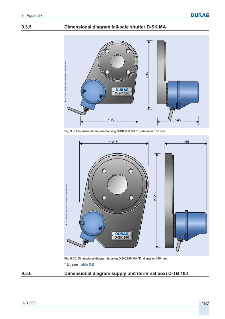
9 | Appendix
D-R 290 187
Dimensional diagram fail-safe shutter D-SK MA
Fig. 9.9: Dimensional diagram housing D-SK 290 MA *D1 diameter 100 mm
Fig. 9.10: Dimensional diagram housing D-SK 280 MA *D1 diameter 150 mm
* D1 see Table 9.8
Dimensional diagram supply unit (terminal box) D-TB 100
9.3.5
9.3.6

9 | Appendix
188 D-R 290
Fig. 9.11: Dimensional diagram D-TB 100 supply unit
Dimensional diagram purge air unit D-BL9.3.7

9 | Appendix
D-R 290 189
WSH Weather protection cover (optional) FR Clear space (for changing the filter)Fig. 9.12: Dimensional diagram purge air unit *D1 diameter 100 mm (*D1 see Table 9.8 )
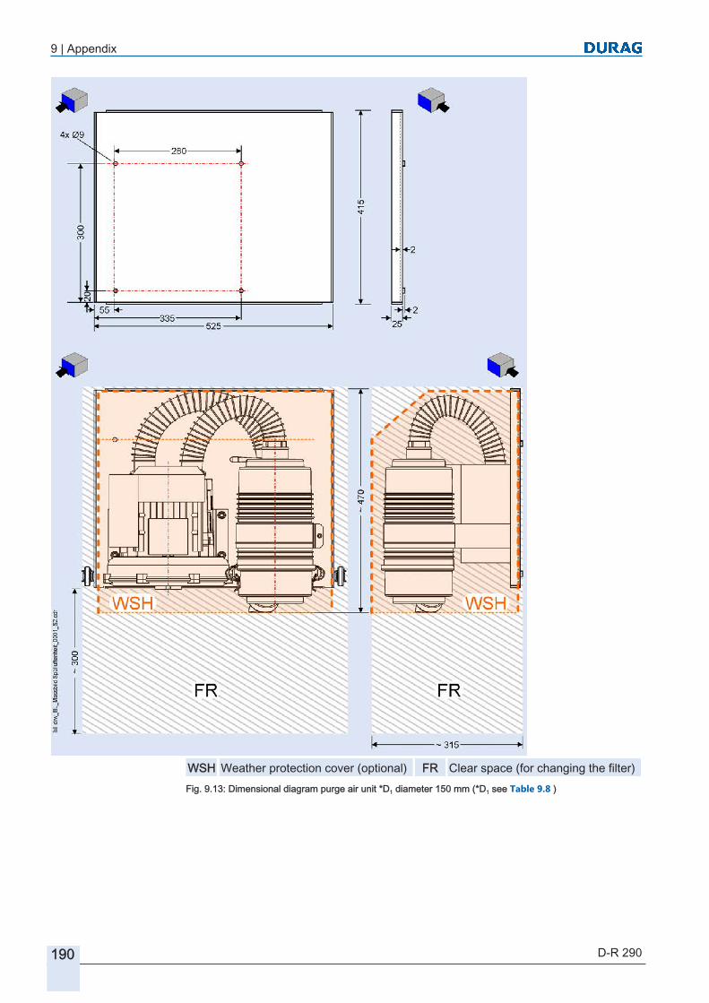
9 | Appendix
190 D-R 290
WSH Weather protection cover (optional) FR Clear space (for changing the filter)Fig. 9.13: Dimensional diagram purge air unit *D1 diameter 150 mm (*D1 see Table 9.8 )

9 | Appendix
D-R 290 191
Dimensional diagram (optional) weather protection covers
Fig. 9.14: Dimensional diagram weather protection cover, measuring head D1 (pitch circle diameter 100)*
Fig. 9.15: Dimensional diagram weather protection cover, reflector D1 (pitch circle diameter 100)*
* D1 see Table 9.8
9.3.8

9 | Appendix
192 D-R 290
Fig. 9.16: Dimensional diagram weather protection cover, measuring head D1 (pitch circle diameter 150)*
Fig. 9.17: Dimensional diagram weather protection cover, reflector D1 (pitch circle diameter 150)*
* D1 see Table 9.8

9 | Appendix
D-R 290 193
Fig. 9.18: Dimensional diagram weather protection cover, control electronics protective device

9 | Appendix
194 D-R 290

10 Glossary
D-R 290 195
10 GlossaryAuto-collimation principle
The collimator (Latin) is a device for generating a parallel beam path. In optics, auto-collimation is understood to mean imaging systems in which the object is in the same plane as the image. In the process, semi-transparent mirrors enable the lens of the collimator to be used simultaneously as the lens of the measuring instrument, thus as far as possible eliminating lens and set-up errors.
D-ESI 100The D−ESI 100 software is a graphical interface for operating and managing sensor devices. The software simplifies the checking and where necessary the parameterisation of bus-based DURAG devices. D−ESI 100 allows individual devices or multiple devices connected via a DURAG - Modbus or USB cable to be identified. Setting parameters (depending on the capabilities of the device concerned) can be read and edited, and measurement results displayed or recorded for maintenance purposes. D-ESI 100 is used on site by maintenance teams and by DURAG service engineers.
D-ISC 100
The D‑ISC 100 universal operation unit was designed for the new generation of DURAG devices. It replaces the various different control, display, evaluation and supply units used by those devices, and creates uniformity in their supply and operation.
EPAThe US Environmental Protection Agency, or either EPA or US EPA for short, is a governmental organisation of the United States of America concerned with the protection of the environment and the protection of human health.
Extinction<lat.>: including (phys.) Attenuation of a wave movement (radiation) when passing through a medium Extinction is also referred to an optical density. By conversion of the transmission into extinction and after a gravimetric comparison measurement, the display is output in mg/m³. By calculation based on the reference variables T, P, RF for dust concentrations this result is given in mg/Nm³.
Gravimetry<lat.>: including (chem.) Measurement analysis; procedure for quantitative determination of elements and groups in substance mixtures.
Hysteresis(Greek: hysteros = afterwards) refers to the continuation of an effect after the removal of its cause. This phenomenon occurs in a wide range of scientific fields. For the fail-safe shutter it is used to program the tolerance that the system permits with respect to the air flow setting before the shutters are opened or closed. This avoids continually opening and closing of the shutters because of normal fluctuations in the air flow.
In situThe term in situ (Latin for at the (original) location, on the premises, "on the spot") in environmental technology denotes the execution of defined procedures on site.
Integration timeThe values are measured at the time intervals defined in the measurement system. However, for various reasons display of the individual measured values is unimportant, it is rather a median value over an adjustable period of time that is required. This time period is defined by the integration time.
IsopropanolIsopropanol or isopropyl alcohol (abbreviated as IPA), also known as 2-propanol, is an alcohol
Modbus RTU(RTU: Remote Terminal Unit ) The Modbus protocol is a communications protocol that is based on a master/slave or client/server architecture. Modbus has become a de facto standard in industry, as it is an open-source protocol. A master (e.g. a PC) and several slaves (e.g. measurement and control systems) can be connected using Modbus.
Offset or adjustment offsetOffset (displacement, distance) in this manual denotes a static value which is added to or subtracted from a measured value, for instance to adjust the zero value.
Opacity-<Latin>: (optics) non-transparency. A light beam is transmitted through a mixture of gases and particles and is thereby attenuated due to absorption and scattering. The more particles there are in the light beam, the higher the degree of

10 Glossary
196 D-R 290
light attenuation. The ratio of the received light to the transmitted light is a measure for the transmission or of the reciprocal opacity
PCSProcess Control System
QAL1(QAL1 certification) Certificate declaring the suitability test of the automatic measuring devices has been passed successfully. DIN EN 14181 stipulates that in Europe only measurement and data recording devices that have passed the suitability test are approved for the officially required measurement and monitoring of emissions. Tested and certified measuring devices for continuous measurement and monitoring of emissions and immissions are also an important basis for reliable protection of the environment. Measuring systems which carry QAL1 certification are characterised by specially high standards of accuracy and reliability. In addition the certificate explicitly lists the individual measurement results and thus permits an optimum choice of the measuring system to be used.
Quantitative(from lat. quantitas: size, amount) refers to the quantity or number of substances or objects (by quantity or by number) or the frequency of processes.
Quick infoQuick info is a small pop-up window with informative content. It is displayed for a certain period of time. To call it up, the user need only hover the mouse cursor over an element (e.g. over a button, a symbol or even a text) to which quick info is associated.
RoHS complianceThe EC Directive restricting the use of hazardous substances in electrical and electronic devices governs the use of hazardous substances in devices and components. This EC Directive, together with the necessary implementation into national law, is denoted by the abbreviation RoHS: Restriction of (the use of certain) hazardous substances. The companies within the DURAG GROUP comply with this directive and they use no substances which are impermissible, i.e. not to be used, according to the RoHS.
RS-485 serial interfacehas been - similarly to the RS 422 interface - developed for serial high-speed data transfer over long distances and is becoming increasingly widespread in the industrial sector. The data cables must be laid as twisted pairs.
SupercapsSupercapacitors are electro-chemical capacitors. They can be quickly charged and discharged, and also remain operational after many more switching cycles than do batteries.
Transmission principleIf light passes through a gas, the attenuation of this light is greater the higher the dust density in the gas. The applied measurement principle is based on comparing the measured value of light that has passed through the gas with that of a light beam that has not been subjected to the effects of dust (twin-beam alternating light process). A computer then calculates the ratio of the measured light beam to the comparison light beam.
Twin-beam alternating light processsee transmission principle

11 Index
D-R 290 197
11 IndexAAddress
setting (Modbus) 121Application
ranges 53Approvals 54Attachment
Purge air unit 101
BBaud rate 123Brick stacks 73
CCalculation
the opacity 46calibration, gravimetric 111, 122, 124, 126, 127,
130, 135, 137, 139, 143Category for maintenance work 155Changing the battery in the measuring head 164Checking the protective device 92Checklist
Parameter checking, device-specific 118Parameter checking, general 117Preconditions for operation 66
Comparison measurement 43Connection
diagram 67Consequential damage 26Contact setting, relay 83Contamination check 161Control cycle 162
Duration of the step 140Interval 140
Control electronics displays 87Critical faults, list 173Customer service information 153
DD1 diameter 52, 185Data cable, specification 67Date, setting of 120Default value
Control measurements 140Fault indication suppression 141Reference value 140
Designated use 53Designation of system components 55Device components, Designation 55Devices
settings, additional 141, 143Dimensional diagram measuring head and reflector
78, 85Dismantling 103Disposal 104double-walled ducts 75Drilling template 186D-SK 290 MA fail-safe shutter 83D‑SK AE control electronics 83
EEmergency stop devices 27Environmental protection 15EPA-Test filter 158Error messages (list) 168, 170, 172, 173Example: double-walled ducts 75Example: Installation in a brick stack 73Example: Thin-walled measurement ducts 74Explanation of Symbols 14
FF3 air flow sensor 83, 88Fail-safe shutter, functional test 163Fault messages
by LED 80Flue stack
- correction factor 48factor 48
Flue stack correction factor 143Functional test of the fail-safe shutter 163
GGravimetric calibration 111, 122, 124, 126, 127,
130, 135, 137, 139, 143
HHazard
due to automatic closing mechanisms 25Hazards due to electrical equipment 24Help function 119

11 Index
198 D-R 290
IInstallation
D-ISC 100 control unit 96D-TB 100 supply unit 97D-TB 100 supply unit, electrical connection 99Measuring head M and reflector RI / II 70Purge air unit 101
Installation sequenceD−R 290 measuring system 69D−R 290 measuring head and reflector 77, 84
Instructionson delivery 31
LLEDs, meaning of 80Limitation of liability 15Login 112Logout 114
MMains supply cable 67, 89Maintenance
Maintenance work, table 155Work 154Work, not permissible 22
measured value-corrections (principle) 130Output channel, setting the 127, 134
Measurement 43Measurement point questionnaire 177Measurement principle 45
Extinction 48Opacity 46Transmission 46
Measuring path, smoke-free 146, 148Measuring point 67Measuring tube 148Messages, list 168Modbus
Independent User Organisation (IDA) 110over Serial Line Specification and Implementation
Guide 110Protocol specifications 110Setting the address 121Setting the Baud rate 123
Motor current protection switchD-SK 290 MA 95Fail-safe shutters 95
Motor current protection switch, purge air unit 102Mounting
Purge Air Unit 147
NNavigation help 109, 119
OOperation 103Operators, definition 23Output variable 128
PParameters
Analogue output 134Fault indication suppression 141Integration time 131Maintenance settings 139Offset 131Reference point check 140Reference value 140Relay logic 137Relay settings 135Save 111, 122, 124, 126, 127, 130, 135, 137,
139Settings 133Signal range 133Slope 132Zero range 133
Password 112PIN
Change code 113Code 111, 112Lock 111Lock activated 114Symbol overview 111
PIN symbol overview 111Pitch circle diameter (LK) 52, 185Possible system configurations 51Preconditions for operation 66Preparation for installation 69Principle of operation 42Program version 119Protective device 53Protective device for the D-SK 290 83Protective equipment, personal 24Purge air motor, connection 115V/230V 102
QQuick info 119

11 Index
D-R 290 199
RReading
corrections 129Red dot 71Reference point
Check 162Measurement 45
Reflectors 52Relay
Contact setting 83Switching logic, configuration of the 138
RelaysOutputs, configuration of the 136
RoHS compliance 104
SSafety instructions, specific 14Save, parameters 111, 122, 124, 126, 127, 130,
135, 137, 139Scope of supply
Equipment, optional 36optional 36Standard 34
Service technicians, definition 23Setting
Analogue output 134Date/time 120Measurement channel variables 125Modbus address 121Modbus communication settings 123Relay settings 136, 138
SettingsD-SK air flow 94Hysteresis D−SK 95Light intensity at the zero point reflector measur
ing head 107Sighting mechanism 108Simple faults, list 172Smoke-free measuring path 146Space requirements 186Spare parts 16, 154Specialised electricians, definition 23Specialised personnel, definition 23Standard systems product short node
990791918270871151002 51Storage conditions 32Supercaps 92Symbols
Further 15System components 51System components, Designation 55
TTechnical data
D-BL xxx purge air unit 181D-R 290 application data 179D-R 290 measuring head 180D-R 290 reflector 180D-R 290 system 179D-SK 290 MA fail-safe shutter protective device
181D-SK 290 AE control electronics protective de
vice 180Temperature compensation 149Temperature transmitter 149Thin-walled measurement ducts 74Time, setting of 120Tips, recommendations 14Transport
Damage 31-Inspection 31
Tube length of the welded-in pipe, maximum 51Type code 128type label
Location of the 58Meaning of the information 59
VVersion 119Visual checking 155
WWarning notices, specific
Caustic 14Electric power 14ESD 15Explosion 14General warning symbol 14Hot surface 15Injuries to the hand 15Read the information and instructions 15
Warning, generalHigh risk - danger 14Lesser risk - caution 14Medium risk - warning 14Risk of equipment/environmental damage - No
tice 14Warnings, list 170Warranty, instructions regarding 16Welded-in pipe lengths 51, 52, 185
ZZero point
Measurement 44-reflector 107

11 Index
200 D-R 290

DURAG GmbHKollaustraße 10522453 Hamburg, GermanyTel. +49 40 55 42 18–0Fax +49 40 58 41 54E-Mail: [email protected]
A Brand ofDURAG GmbH
A Brand ofDURAG GmbH
DURAG data systems GmbHKollaustraße 10522453 Hamburg, GermanyTel. +49 40 55 42 18–3000Fax +49 40 55 42 18–3099E-Mail: [email protected]
A Brand ofDURAG data systems GmbHBranch Office AustriaLadenstraße 36, City Tower 24020 Linz, AustriaTel. +43 732 60 99 60–0Fax +43 732 60 99 60–4E-Mail: [email protected]
DURAG Siena do Brasil LtdaRua Vinte e Dois de Agosto, 66Diadema – SP09941–530 BrasilTel.: +55 11 4071-5050 r.28Fax.: +55 11 4077-1718E-Mail: [email protected]
Hegwein GmbHAm Boschwerk 7 70469 Stuttgart, GermanyTel. +49 711 135 788–0Fax +49 711 135 788–5E-Mail: [email protected]
Smitsvonk Holland B.V.P.O.Box 1802700 AD ZoetermeerGoudstraat 6,2718 RC ZoetermeerNetherlandsTel. +31 79 361 35 33Fax +31 79 361 13 78E-Mail: [email protected]
GRIMM Aerosol TechnikGmbH & Co. KGDorfstraße 983404 Ainring, GermanyTel. +49 8654 578–0Fax +49 8654 578–35E-Mail: [email protected]
DURAG Sales and MarketingGmbH & Co. KGKollaustraße 10522453 Hamburg, GermanyTel. +49 40 55 42 18–0Fax +49 40 58 41 54E-Mail: [email protected]
DURAG BrazilDURAG Siena do Brasil LtdaRua Vinte e Dois de Agosto, 66Diadema – SP09941-530 BrasilTel.: +55 11 4071–5050 r.28Fax.: +55 11 4077–1718E-Mail: [email protected]
DURAG France S.a.r.l.147 avenue Paul Doumer92500 Rueil MalmaisonFranceTel. +33 1 412 904 60Fax +33 1 412 904 68E-Mail: [email protected]
DURAG, Inc.1355 Mendota Heights Road,Suite 200Mendota Heights,MN 55120, USATel. +1 651 451–1710Fax +1 651 457–7684E-Mail: [email protected]
DURAG India InstrumentationPrivate Limited#27/30, 2nd Main Road,Industrial Town, RajajinagarBengaluru 560 044, IndiaTel.: +91 80 2314 5626, 2301 1700Fax: +91 80 2314 5627E-Mail: [email protected]
DURAG Instrumentation(Shanghai) Co.,Ltd.Room 706, Dibao Plaza, No.3998Hongxin Rd., Minhang District,Shanghai, 201103PR ChinaTel.: +86 21 60732979–200Fax: +86 21 60732980–205E-Mail: [email protected]
DURAG Italia S.r.lVia Carlo Panseri, 118CIM uffici, P. secondo28100 NovaraItalyTel. +39 0321 679569Fax +39 0321 474165E-Mail: [email protected]
DURAG Japan Officec/o TMS Planning Inc.291–2 Umena, Mishima–shi,Shizuoka–ken411–0816 JapanTel.: +81 55 977–3994Fax.: +81 55 977–3994E-Mail: [email protected]
DURAG Korea OfficeRM#1131, Manhattan Building,36–2, Yeouido–Dong,Yeongdeungpo–Gu, SeoulKoreaTel.: +82 2 761–8970Fax.: +82 2 761–8971E-Mail: [email protected]
DURAG Middle East (Branch)Dubai Airport Free Zone5 West Wing, Office 124Dubai, UAEP.O. Box 371555Tel. +971 4260251 0E-Mail: [email protected]
DURAG Russ OOOAndropova avenue18/6Office 5–09115432 MoscowRussiaTel.: +7 499 4180090Fax: +7 499 4180091E-Mail: [email protected]
DURAG UK GmbHBretby Business Park, Ashby RoadBurton-on-Trent, Staffordshire,DE15 0YZGreat BritainTel. +44 1283 553 481Fax +44 1283 553 482E-Mail: [email protected]
DURAG Branch NorthKollaustraße 10522453 Hamburg, GermanyTel. +49 40 55 42 18–0Fax +49 40 58 41 54E-Mail: [email protected]
DURAG Branch EastHalsbrücker Str. 3409599 Freiberg, GermanyTel. +49 3731 30 04–0Fax +49 3731 30 04–22E-Mail: [email protected]
DURAG Branch SouthWeidenweg 1673087 Bad Boll, GermanyTel. +49 7164 912 25–0Fax +49 7164 912 25–50E-Mail: [email protected]
DURAG Branch WestAn der Pönt 53a40885 Ratingen, GermanyTel. +49 2102 74 00–0Fax +49 2102 74 00–28E-Mail: [email protected]
Credits: (1) … www.durag.com

GmbH • Kollaustraße 105 • 22453 Hamburg • Germany • www.durag.com