Embed Size (px)
Citation preview
Man-Machine Interaction Model for Occupational Risk Modelling
Besrour Adel, Didier Buchs
Software Engineering Laboratory, Swiss Federal Institute for Technology1015 Lausanne, Switzerland
{Adel.Besrour,Didier.Buchs}@epfl.ch
Abstract. This paper defines the MORM Model (Man-Machine Occupational Risk Modelling) which is devised formodeling risk in wide-scaled industrial systems. We introducethe basic principles of the Human-Machine interaction modelbased on a dynamic approch on one hand on the extendedCognitive Reliability and Error Analysis Method (extendedCREAM) and on the other hand on a high level Petri Net for-malism called CO-OPN (Concurrent Object-Oriented PetriNets). To illustrate the MORM Model we adapted a case studyof a metal wire making process.
1 Introduction
Nowadays, systems’ complexity increases (size, com-ponent number, ramification, automation level,...) in the in-dustry while protection of workers is more demanding.Production systems are higher priced and more specific sothat more dangerous since there’s not enough statistic dataabout their use. As a result, potential occupational acci-dents in such process are more acute and then less accepta-ble. Thus the occupational risk should be processedprecociously and methodically.
The literature of Risk Analysis (RA) holds many meth-ods [1][2] that deals with Risk management and Occupa-tional Health and Safety (OH&S). Most of these methodsare based on static evaluation of danger. Despite of thesenumerous RA methods, it must be emphasized that Model-ling accident processes involving complex time relation-ships is still challenging. Recently, development ofdynamic simulation tools [3], such as colored Petri nets(CPNs), have shown promising results in such modelling.This variety of methods might be System-oriented calledalso Process-oriented or Machine-oriented. Man orientedRA methods are generally focused on the experience of theOH&S experts, thus often not sufficient in the context ofnew systems. Our work’s aim is to develop a model of theHuman-Dynamic Process System interaction model suita-ble for Occupational Risk managment: “Man-Machine Oc-cupational Risk Modelling” (MORM). MORM might be
seen as “Man-Oriented Risk Analysis method” with aProcess-Oriented facet since it models the Machines’ sys-tem and its Environment.
In this paper we present a Human-Machine inter-action model based on a dialect of Petri Nets called CO-OPN (Concurrent Object Oriented Petri Nets). We willmainly present the modelling aspects at the machine leveland on the system level obtained by interconnecting ele-mentary machine. Available analysis techniques will besuggested in order to clarify the expectation of the MORMmethod in terms of risk prediction. Analysis results areprincipally obtained by simulation of the whole systemmodel.
2 MORM context
Initially developed in ‘sensitive’ fields, such as nucle-ar or chemical plant safety, systematic risk analysis meth-ods are still mainly used to prevent major industrial risks.The Modelling concepts and the developed tools are usedonly at a very limited extend in the OH&S field, in whicha posteriori analysis is prevalent.
2.1 Existing Risk Analysis Methods
Risk analysis methods are empirical and belong basi-cally to three main family:
Inductive such as AMDEC (Analyse des Modes deDéfaillance et d’Effets et Criticalité), HAZOP (HAZardand OPerability study) or HACCP (Hazard Analysis andCritical Control Points);
Deductive such as FTA (Fault Tree), RCA (RootCause Analysis) that are more used in the computer-assist-ed RA domain;
Hybrid such as MOSAR (Méthode Organiséé et Sys-témique d’Analyse de Risque).
Retrospective methods pose ethical problems, besidesit must be emphasized that such approaches are of limiteduse to prevent health diseases in complex changing work-
1
places, such as machine, robotic tools and above all dynam-ic process systems.
2.2 Deficiencies of the existing Methods
Despite this variety of the accident theories availableat this time, dynamic system Modelling is still difficult [4].Classical Risk Analysis methods, particularly in Occupa-tional Health and Safety, present some limitations such assingle-orientation (Man or Process-Oriented), inability tosimulate time constraints, and dependency on the expertjudgement. Besides, being largely dependent on Man-Ma-chine relationships, workplace hazards can not be ad-dressed through a single-oriented approach. Moreoverthese methods do not provide reasonable results in Model-ling accident processes involving complex time relation-ships.
2.3 Basic motivation of our approach
This last point is the main aspect where Colored Petrinets, and its variety of dynamic simulation tools haveshown promising results in such Modelling. Our researchwork is focused on modelling the Human Machine interac-tion with a dynamic approch. Moreover, dynamic mode-ling tools based on a strong mathematical semantics can beused to predict behaviour with more accuracy.
3 Illustrative Example
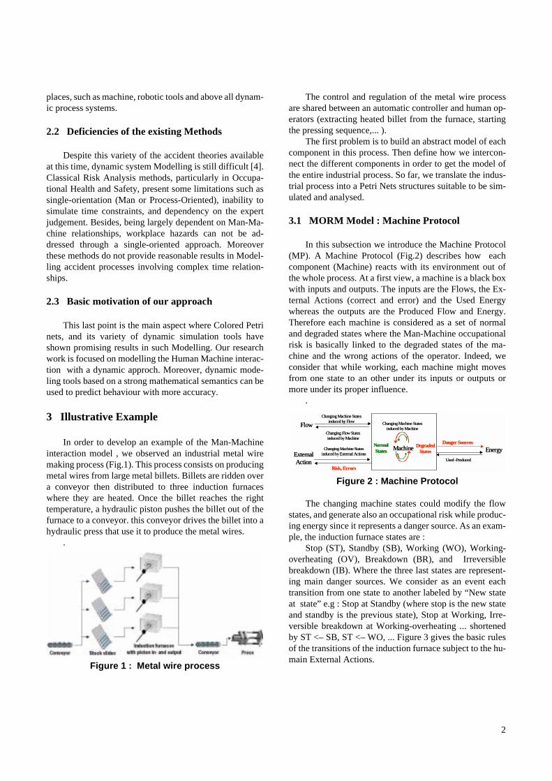
In order to develop an example of the Man-Machineinteraction model , we observed an industrial metal wiremaking process (Fig.1). This process consists on producingmetal wires from large metal billets. Billets are ridden overa conveyor then distributed to three induction furnaceswhere they are heated. Once the billet reaches the righttemperature, a hydraulic piston pushes the billet out of thefurnace to a conveyor. this conveyor drives the billet into ahydraulic press that use it to produce the metal wires.
.
Figure 1 : Metal wire process
The control and regulation of the metal wire processare shared between an automatic controller and human op-erators (extracting heated billet from the furnace, startingthe pressing sequence,... ).
The first problem is to build an abstract model of eachcomponent in this process. Then define how we intercon-nect the different components in order to get the model ofthe entire industrial process. So far, we translate the indus-trial process into a Petri Nets structures suitable to be sim-ulated and analysed.
3.1 MORM Model : Machine Protocol
In this subsection we introduce the Machine Protocol(MP). A Machine Protocol (Fig.2) describes how eachcomponent (Machine) reacts with its environment out ofthe whole process. At a first view, a machine is a black boxwith inputs and outputs. The inputs are the Flows, the Ex-ternal Actions (correct and error) and the Used Energywhereas the outputs are the Produced Flow and Energy.Therefore each machine is considered as a set of normaland degraded states where the Man-Machine occupationalrisk is basically linked to the degraded states of the ma-chine and the wrong actions of the operator. Indeed, weconsider that while working, each machine might movesfrom one state to an other under its inputs or outputs ormore under its proper influence.
.
Figure 2 : Machine Protocol
The changing machine states could modify the flowstates, and generate also an occupational risk while produc-ing energy since it represents a danger source. As an exam-ple, the induction furnace states are :
Stop (ST), Standby (SB), Working (WO), Working-overheating (OV), Breakdown (BR), and Irreversiblebreakdown (IB). Where the three last states are represent-ing main danger sources. We consider as an event eachtransition from one state to another labeled by “New stateat state” e.g : Stop at Standby (where stop is the new stateand standby is the previous state), Stop at Working, Irre-versible breakdown at Working-overheating ... shortenedby ST <– SB, ST <– WO, ... Figure 3 gives the basic rulesof the transitions of the induction furnace subject to the hu-main External Actions.
External Action
Flow
Danger SourcesEnergy
Changing Machine Statesinduced by Flow
Changing Flow States induced by Machine
MachineChanging Machine States induced by External Actions
Risk, Errors
Changing Machine Statesinduced by Machine
Used -Produced
Normal States
Degraded States External
Action
Flow
Danger SourcesEnergy
Changing Machine Statesinduced by Flow
Changing Flow States induced by Machine
MachineChanging Machine States induced by External Actions
Risk, Errors
Changing Machine Statesinduced by Machine
Used -Produced
Normal States
Degraded States
2
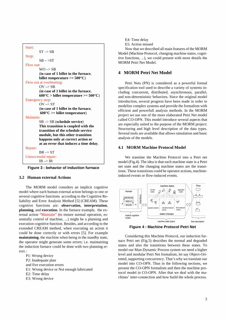
Figure 3 : behavior of induction furnace
3.2 Human external Actions
The MORM model considers an implicit cognitivemodel where each human external action belongs to one orseveral cognitive functions according to the Cognitive Re-liability and Error Analysis Method [5] (CREAM). Thesecognitive functions are: observation, interpretation,planning, and execution. In the furnace example, the ex-ternal action “Maintain” (to ensure normal operation, es-sentially control of machine, ...) might be a planning andexecution cognitive function. Besides, and according to theextended CREAM method, when executing an action itcould be done correctly or with errors [5]. For examplemaintaining, the machine when being in the standby state,the operator might generate some errors; i.e. maintainingthe induction furnace could be done with two planning er-rors :
P1: Wrong deviceP2: Inadequate planand five execution errorsE1: Wrong device or Not enough lubricatedE2: Time delayE3: Wrong device
E4: Time delayE5: Action missedNow that we described all main features of the MORM
Model (Machine Protocol, changing machine states, cogni-tive functions, ...), we could present with more details theMORM Petri Net Model.
4 MORM Petri Net Model
Petri Nets (PN) is considered as a powerful formalspecification tool used to describe a variety of systems in-cluding concurrent, distributed, asynchronous, parallel,and non-deterministic behaviors. Since the original modelintroduction, several progress have been made in order tomodelize complex systems and provide the formalism withefficient and powerfull analysis methods. In the MORMproject we use one of the more elaborated Petri Net modelcalled CO-OPN. This model introduce several aspects thatare especially suited to the purpose of the MORM project:Structuring and high level description of the data types.Several tools are available that allows simulation and basicanalysis of the models.
4.1 MORM Machine Protocol Model
We translate the Machine Protocol into a Petri netmodel (Fig.4). The idea is that each machine state is a Petrinet state and the changing machine states are the transi-tions. These transitions could be operator actions, machine-induced events or flow-induced events.
Figure 4 : Machine Protocol Petri Net
Considering this Machine Protocol, our induction fur-nace Petri net (Fig.5) describes the normal and degradedstates and also the transitions between these states. Tomodel our Man-Dynamic Process system we need a higherlevel and modular Petri Net formalism, let say Object-Ori-ented, supporting concurrency. That’s why we translate ourmodel into CO-OPN. Thus in the following sections, wepresent the CO-OPN formalism and then the machine pro-tocol model in CO-OPN. After that we deal with the ma-chines’ inter-connection and how build the whole process.
Start: ST –> SB
Stop: SB – >ST
Flow out: WO –> SB (in case of 1 billet in the furnace, billet temperature >= 500°C)
Flow out at overheating: OV –> SB (in case of 1 billet in the furnace, 600°C > billet temperature >= 500°C)
Emergency stop: OV –> ST (in case of 1 billet in the furnace, 600°C >= billet temperature)
Maintain: SB –> SB (schedule service) This transition is coupled with the transition of the schedule service module, but this other transition happens only at correct action or at an error that induces a time delay.
Repair: BR –> ST
Unsuccessful repair: IB –> IB
machine states Flow
Inte
rface
Human
states changes
normal states
degraded states
operator actions
implicit cognitive model
KNOWLED
SKILLS
RULESmachine-induced events
flow-induced events
machine state space flow description
3
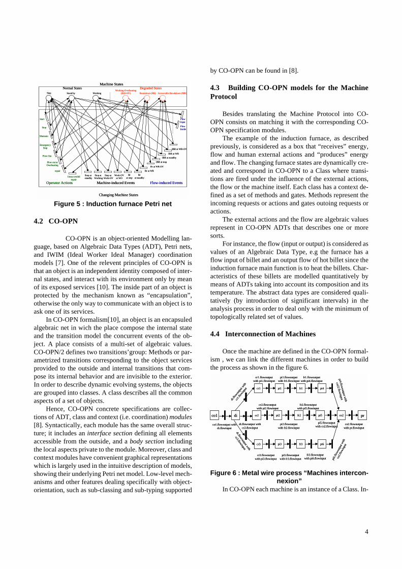
Figure 5 : Induction furnace Petri net
4.2 CO-OPN
CO-OPN is an object-oriented Modelling lan-guage, based on Algebraic Data Types (ADT), Petri nets,and IWIM (Ideal Worker Ideal Manager) coordinationmodels [7]. One of the relevent principles of CO-OPN isthat an object is an independent identity composed of inter-nal states, and interact with its environment only by meanof its exposed services [10]. The inside part of an object isprotected by the mechanism known as “encapsulation”,otherwise the only way to communicate with an object is toask one of its services.
In CO-OPN formalism[10], an object is an encapsuledalgebraic net in wich the place compose the internal stateand the transition model the concurrent events of the ob-ject. A place consists of a multi-set of algebraic values.CO-OPN/2 defines two transitions’group: Methods or par-ametrized transitions corresponding to the object servicesprovided to the outside and internal transitions that com-pose its internal behavior and are invisible to the exterior.In order to describe dynamic evolving systems, the objectsare grouped into classes. A class describes all the commonaspects of a set of objects.
Hence, CO-OPN concrete specifications are collec-tions of ADT, class and context (i.e. coordination) modules[8]. Syntactically, each module has the same overall struc-ture; it includes an interface section defining all elementsaccessible from the outside, and a body section includingthe local aspects private to the module. Moreover, class andcontext modules have convenient graphical representationswhich is largely used in the intuitive description of models,showing their underlying Petri net model. Low-level mech-anisms and other features dealing specifically with object-orientation, such as sub-classing and sub-typing supported
by CO-OPN can be found in [8].
4.3 Building CO-OPN models for the MachineProtocol
Besides translating the Machine Protocol into CO-OPN consists on matching it with the corresponding CO-OPN specification modules.
The example of the induction furnace, as describedpreviously, is considered as a box that “receives” energy,flow and human external actions and “produces” energyand flow. The changing furnace states are dynamically cre-ated and correspond in CO-OPN to a Class where transi-tions are fired under the influence of the external actions,the flow or the machine itself. Each class has a context de-fined as a set of methods and gates. Methods represent theincoming requests or actions and gates outoing requests oractions.
The external actions and the flow are algebraic valuesrepresent in CO-OPN ADTs that describes one or moresorts.
For instance, the flow (input or output) is considered asvalues of an Algebraic Data Type, e.g the furnace has aflow input of billet and an output flow of hot billet since theinduction furnace main function is to heat the billets. Char-acteristics of these billets are modelled quantitatively bymeans of ADTs taking into account its composition and itstemperature. The abstract data types are considered quali-tatively (by introduction of significant intervals) in theanalysis process in order to deal only with the minimum oftopologically related set of values.
4.4 Interconnection of Machines
Once the machine are defined in the CO-OPN formal-ism , we can link the different machines in order to buildthe process as shown in the figure 6.
Figure 6 : Metal wire process “Machines intercon-nexion”
In CO-OPN each machine is an instance of a Class. In-
Machine States
Machine-induced EventsOperator Actions Flow-induced Events
Normal States Degraded States
Changing Machine States
Stop Stand by WorkingWorking-Overheating
(WO-OV) Breakdown (BR) Irreversible Breakdown (IBR)
Start
Stop
Flow Out
Maintain
Unsuccessful repair
Flow out at Overheating
Emergency Stop
repair
Flow Input
Flow Inside
Stop at standby
Stop at Working
Stop at Work-OV
Work-OVat WO
Br at stop
Br at standby
Br at WR
Br at WR-OV
IBR at stop
IBR at standby
IBR at WR
IBR at WR-OV
co1 di
cr1
cr3
co1.flowoutput with di.flowinput
cr2
di.flowoutput with cr2.flowinput
di.flo
woutpu
t with
cr1.flo
winput
di.flowoutput with
cr3.flowinput
pi1
pi2
pi3
fr1 pi4
fr2 pi5
fr3 pi6
pr
cr2.flowoutput with pi2.flowinput
pi2.flowoutput with fr2.flowinput
fr2.flowoutput with pi5.flowinput
cr3.flowoutput with pi3.flowinput
pi3.flowoutput with fr3.flowinput
fr3.flowoutput with pi6.flowinput
cr1.flowoutput with pi1.flowinput
pi1.flowoutput with fr1.flowinput
fr1.flowoutput with pi4.flowinput
co2
pi5.flowoutput with co2.flowinput
pi6.f
lowo
utpu
t with
co2.f
lowi
nput
pi4.flowoutput w
ith
co22.flowinput
co2.flowoutput with pr.flowinput
4
terconnecting the machines consists on linking the out go-ing flows of a machine (output flow) with of the incomingflows of an other (input flow). This interconnection is en-sured by a synchronization mechanism of CO-OPN. In theillustrative example, the billet is moved from a crawl (cr)into a furnace (fr) by a piston (pi). The billet represents themetal flow, and the interconnection between the crawl, thepiston and the furnace is expressed by a synchronization ofthe flow movement since outgoing from the crawl into itsdelivery by the piston to the furnace. This interconnection(Fig.6) is summarized by two synchronization events: 1. cr.flowoutput with pi.flowinput,2. pi.flowoutput with fu.flowinput.
The complexity of the machines interconnection de-pends on the number of the flows and also on the complex-ity of the flow (the number of relevent properties of theflow in the process : temperature, chemical composition,lenght, ...).
5 Analysis and expected results
Modelling the machines with a high level Petri Netwas basically motivated by the simulation and analysis ca-pability of such model. The future steps in our work willbe first to simulate the whole process by building the reach-ability tree of the whole system and computing the proba-bilities to attemp a specific state. this will be done byadapting our current code generator integrated in the Coop-nTools development environment [12]. In particular dan-gerous states will be mainly considered. The final step, willbe to develop an analysis algorithm, built over the simula-tion tool , in order to extract manipulate additional risk anddanger data based on timing aspects. Temporal extensionsof CO-OPN [11] will be considered in order to managesuch informations.
These main steps would be supported by correspond-ing softwares.
6 Conclusion
Risk analysis is currently based on manual construc-tion of the causal relations of events leading to accident. Inthe MORM approach we propose to consider predictivemethods were only limited accidental knowledge of thecomponents are known. In this paper we have explored atechniques using modularity principles and probabilisticdescriptions based on Petri Nets that can lead to dynamicprediction of risks induced by the complexity of the linksbetween components.
7 References
[1] Imre J.Rudas and Laszl Horvath ``Modelling of Manufac-turing Process Using a Petri-net Representation'', EngngApplic.Artif.Intell.Vol. 10, No. 3, pp.243-255, 1997.
[2] H.Yoshikawa, T.Nakagawa, Y:Nakatani, TFuruta andA.Hasegewa``Development of an Analysis Support ForMan-Machine System Design Information'', ControlEng. Practice, Vol.5, No. 3,pp. 417-425, 1997.
[3] Li-Chih Wang and Shao-ying Wu``Modelling with Color-ed Timed Object-Oriented Petri-Nets for AutomatedManufacturing Systems'', Computer ind, Engng Vol. 34,No. 2, pp 463-480, 1998.
[4] Tom Kontogiannis, Vrassidas Leopoulos and Nikos Mar-mars ̀ `A Comparison of accident analysis techniques forsafety-critical man-machine systems'', International Jour-nal of Industrial Ergonomics, No. 25, pp 327-347, 1999.
[5] E.Hollnagel ``Cognitive reliability and error analysismethod'',Elsevier, Oxford. 1998.
[6] M.Katsumata, M.Kurihara and A.Ohuchi``Serial FailureDiagnosis of a Distributed Processing System by PetriNets'', Computers Math, Vol. 31, No. 9, pp 57-62, 1996.
[7] Didier Buchs and Nicolas Guelfi ̀ `A Formal SpecificationFramework for Object-Oriented Distributed Systems'',IEEE Transactions on Software Engineering, vol. 26, No. 7,pp. 635-652, July 2000.
[8] Olivier Biberstein ̀ `CO-OPN/2 An Object-Oriented For-malism for the Specification of Concurrent System'',Thèse de Docteur en Sciences, mention informatique, No.2919, Genève, 1997.
[9] [9].Zouakia Rochdi, Bouamia Driss and Tkiouat Moham-ed]``Industrial systems maintenance Modelling usingPetri nets'', Reliability Engineering and System Safety, No.65, pp 119-124, 1999.
[10] Olivier Biberstein, Didier Buchs and Nicolas Guelfi, ``Ob-ject-Oriented Nets with Algebraic Specifications: TheCO-OPN/2 Formalism,'' Advances in Petri Nets on Ob-ject-Orientation, G. Agha and F. De Cindio and G. Rozen-berg (Ed.), Lecture Notes in Computer Science, no. 2001,Springer-Verlag, May 2001, pp. 70-12.
[11] Giovanna Di Marzo Serugendo, Dino Mandrioli, DidierBuchs, and Nicolas Guelfi; Real-Time SynchronizedPetri Nets, International Conference on Theory and Appli-cation of Petri Nets, Adelaïde, Australia, Springer Verlag,2002.
[12] S. Chachkov, D. Buchs, From Formal Specifications toReady-to-Use Software Components: The ConcurrentObject Oriented Petri Net Approach , International Con-ference on Application of Concurrency to System Design,Newcastle, pp. 99-110, IEEE Press, june 2001.
5


![Interaction ofPhenylbutazone with [I2C!13C]Warfarin...Stereoselective Interaction ofPhenylbutazone with [I2C!13C]Warfarin Pseudoracemates in Man ROBERTA. O'REILLY, WILLiAM F. TRAGER,](https://img.pdfslide.net/doc/110x75/60a3d21e30f7fc384e0590e9/interaction-ofphenylbutazone-with-i2c13cwarfarin-stereoselective-interaction.jpg)