Embed Size (px)
Citation preview

Management of Dish Concentrator Off-Axis Reflections G. Burgess, P. Scott, J. Preston and K. Lovegrove
School of Engineering, Australian National University Canberra, ACT, 0200.
ABSTRACT The ANU dish concentrator, SG4, achieves peak concentration ratios of the order of 14,000x. These high fluxes must be carefully managed to avoid off-axis reflections damaging the dish structure, or creating a hazard in the surrounding environment. Ray tracing using Opticad 10.0 was used to predict peak fluxes on the receiver support structure in a variety of dish-sun positions. Transient and steady-state temperatures of the irradiated receiver trusses were modelled using Strand7 FEM software.
A custom written ray tracing program is used to predict reflections onto the dish structure, as well as to the surrounding environment. The program is used to develop strategies for moving the dish to positions required for demonstration or maintenance. Radiation levels on the dish surface were both modelled and measured. Suitable eye protection is required for accessing the dish surface.
INTRODUCTION Construction of the first prototype of a new design of paraboloidal dish was completed at the Australian National University (ANU) campus in mid-2009. The dish, known as SG4, has an aperture area of 489 m² in an approximately octagonal profile, with a receiver mounted at the apex of three lightweight truss structures (see Figure 1).
Figure 1. SG4 dish (Photo: Paul Scott).
A feature of the dish is the high quality optics, with a geometric concentration ratio of ~ 3900 for 90% capture, and peak concentration of ~14,000x (Lovegrove et al, 2010). A corollary of these high concentrations is that off-axis reflections from the dish mirror
Solar2010, the 48th AuSES Annual Conference
1-3 December 2010, Canberra, ACT, Australia
2
surface (i.e. reflections produced whenever the dish axis is not pointing directly at the sun) have the potential to be of damaging intensity. This paper describes the modelling of off-axis reflection direction and intensity; the consideration of effects on objects and personnel; and the strategies used to manage the risk of damage and injury.
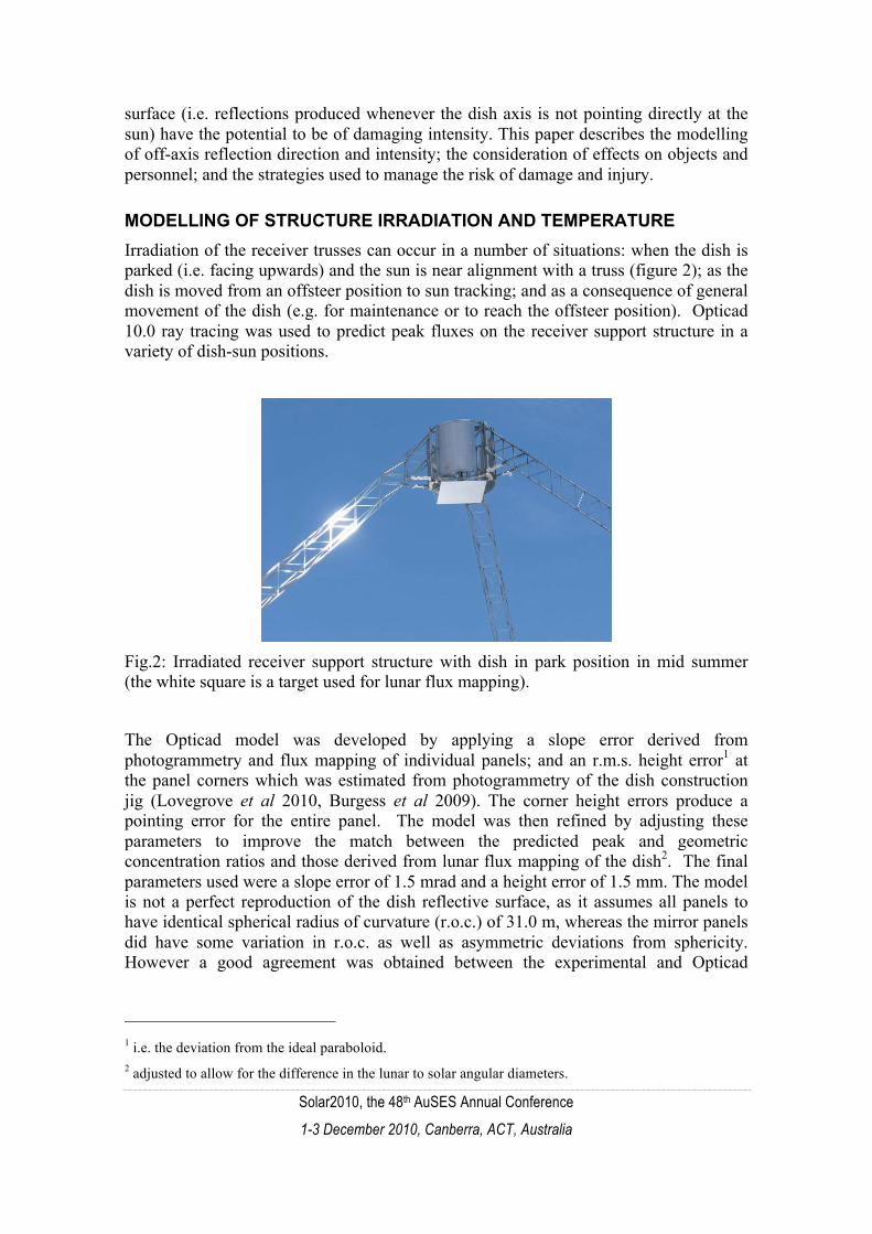
MODELLING OF STRUCTURE IRRADIATION AND TEMPERATURE Irradiation of the receiver trusses can occur in a number of situations: when the dish is parked (i.e. facing upwards) and the sun is near alignment with a truss (figure 2); as the dish is moved from an offsteer position to sun tracking; and as a consequence of general movement of the dish (e.g. for maintenance or to reach the offsteer position). Opticad 10.0 ray tracing was used to predict peak fluxes on the receiver support structure in a variety of dish-sun positions.
Fig.2: Irradiated receiver support structure with dish in park position in mid summer (the white square is a target used for lunar flux mapping).
The Opticad model was developed by applying a slope error derived from photogrammetry and flux mapping of individual panels; and an r.m.s. height error1 at the panel corners which was estimated from photogrammetry of the dish construction jig (Lovegrove et al 2010, Burgess et al 2009). The corner height errors produce a pointing error for the entire panel. The model was then refined by adjusting these parameters to improve the match between the predicted peak and geometric concentration ratios and those derived from lunar flux mapping of the dish2. The final parameters used were a slope error of 1.5 mrad and a height error of 1.5 mm. The model is not a perfect reproduction of the dish reflective surface, as it assumes all panels to have identical spherical radius of curvature (r.o.c.) of 31.0 m, whereas the mirror panels did have some variation in r.o.c. as well as asymmetric deviations from sphericity. However a good agreement was obtained between the experimental and Opticad
1 i.e. the deviation from the ideal paraboloid. 2 adjusted to allow for the difference in the lunar to solar angular diameters.

Solar2010, the 48th AuSES Annual Conference
1-3 December 2010, Canberra, ACT, Australia
3
predicted fluxes on a target at the focal plane (the difference between the concentration ratios was ≤ 2%), and the model is sufficiently accurate for the purposes of this study.
Irradiation on parked dish receiver support trusses Figure 3 shows the predicted concentrations on the inwards and side faces of the longitudinal SHS truss elements, in the configuration of the dish parked and the sun directly aligned with a truss. Peak concentrations rise steeply when the dish is pointing closer than 20° to the sun.
Fig.3: Peak concentration on the receiver support structure for parked dish (pointing to vertical), for the case of the truss directly aligned with the sun azimuth. The concentrations decrease near 90˚ as the focus moves off the support and onto the receiver.
The modelling shown in fig 3 can also be used for the case of the dish elevated away from park, with a dish-sun altitude angle offset set equal to the complement of the value shown in the figures.
Truss element temperatures The fluxes on the irradiated faces of the truss members were used as inputs in a transient heat model developed in Strand7 FEA software. The model incorporates radiation and convection losses from the member outer faces, as well as conduction along and around the SHS. Strand7 cannot, however, model the radiative heat transfer between two surfaces, which limits the accuracy of the model, as there can be significant radiation between the inner surfaces of the SHS member, which would smooth out the temperature distribution around a cross-section of the SHS.

Solar2010, the 48th AuSES Annual Conference
1-3 December 2010, Canberra, ACT, Australia
4
For a sun elevation of 70˚ a near steady state temperature of > 800˚ C was reached after ~ 5 minutes of irradiation3. In this temperature range the yield strength and elastic modulus of structural steel decrease significantly (Standards Australia, 1998; Chena and Young, 2008), so that there is the possibility of buckling failure. These high temperatures could be avoided if the dish is always tracking the sun, or else moved in azimuth so that the sun is never aligned with a truss. However the possibility of power or motor failure or accidental incorrect positioning of the dish means that this would not be a failsafe solution. The preferred alternative is the installation of non-structural radiation shields in front of the vulnerable sections of the trusses.
A more accurate heat transfer model incorporating internal radiation could be used to predict thermal stresses and truss failure due to combined thermal and mechanical load. However the rise in concentration for sun elevation > 70˚ is so steep that it would be unwise to set a safe operation threshold based on modelling of steady-state truss temperatures in this region. Instead the Strand7 model has been used to conservatively define the sections of the trusses which require protection.
PREDICTION OF REFLECTIONS ONTO STRUCTURE AND SURROUNDINGS As the dish is moved off-axis (e.g. to a fully elevated position in order to carry out receiver maintenance) high concentration reflections can be produced in the surrounding environment. These reflections can be difficult to anticipate, and a number of options for ensuring safe movement strategies were considered:
• Opticad modelling was not used as it would be a complex task to incorporate the desired features of objects in the surrounding environment (radiometers in Opticad), a dish with variable location and orientation in space, and a variable sun position. Further effort would be required to automate the output profiles to simplify interpretation.
• Analytic expressions for the regions of high intensity (caustics) generated by a perfect paraboloid with off-axis incident light are given by Shealy and Burkhard (1973) and Scarborough (1964). However the flux on a general surface away from the caustic is not given.
• Building predictive algorithms into the dish control software4 that would prevent or warn the operator of hazardous positioning of the dish. However the complexity of the problem makes it difficult to implement in real-time in the controller, and it is desirable to be able to simulate movement so that a safe path can be determined in advance.
3 The steady state temperature depends on the emissivity assigned to the steel members. The models were run with two different values for the emissivity (ε = 0.3 and 0.5). This quantity is not known accurately as equipment is not available to measure it in situ, and it can vary due to the radiation burning the paint or galvanized coating. 4 The controller is currently a Yokogawa FA-M3 PLC with both sequence (ladder logic) and BASIC CPUs, the latter primarily being used for the sun position algorithm. The FA-M3 is soon to be replaced by a Yokogawa HXS10 sun-tracking controller.

Solar2010, the 48th AuSES Annual Conference
1-3 December 2010, Canberra, ACT, Australia
5
• A purpose written, interactive, ray-tracing program with graphical and tabular output.
The final approach was taken, with a ray-tracing program, dishreflec, being written in IDL 7.0. dishreflec can be used to predict the intensity of off-axis reflections as the dish is moved between two orientations, for a given sun position, which is either entered manually or calculated from a date and time. The output is displayed both as a numeric summary and as a visual representation of irradiation on relevant objects.
dishreflec reads in positional information about surrounding objects, such as nearby trees, a road and bike path adjacent to the dish, and elements of the dish structure such as the receiver trusses. The GUI displays the distribution of rays and total percentage of energy on each object. By running simulations of common movements, it is possible to work out generic rules. It is then possible to fully automate some common movement tasks by implementing these rules into the dish controller.
The program currently approximates the dish with a perfect paraboloid and the sun as a point source, and consequently tends to overestimate the irradiation intensity. Further development would include incorporation of slope error and a more realistic sun shape.
Fig.4: Sample image from dishreflec. The curving row of markers on the left represents the bike path adjacent to the dish, whilst the wider spaced markers from the top right are the road, and the dish perimeter is the semi-circle in the top middle. Each cross represents a bundle of reflected rays. The strong concentration of crossed adjacent to the dish represents an intense reflection onto the ground, and there is also significant reflection onto the road. The combination of sun and dish position would thus be regarded as unacceptable.

Solar2010, the 48th AuSES Annual Conference
1-3 December 2010, Canberra, ACT, Australia
6
PERSONNEL ACCESSING THE DISH SURFACE
Optical hazards A review and analysis of the possibility of eye damage caused by reflections from solar concentrators is given by Ho et al (2009). They consider both glint (“a momentary flash of light”) and glare (“a more continuous source of excessive brightness”) produced by various concentrator geometries. They state that earlier studies generally use irradiance levels corresponding to irreversible eye damage as the safe limit, whereas they propose much lower safe levels, based on the threshold for flash blindness. They assume an exposure of 0.15 sec, corresponding to the normal blink response of the eye, i.e. that there is only momentary viewing of a very bright specular or diffuse reflection.
It is possible to walk on the SG4 dish reflective surface; this is sometimes required for maintenance or other tasks (e.g. the development of an automated, dish-mounted, cleaning system). It is not always practical to schedule such work for cloudy days or night-time. Furthermore, when personnel are working on the surface of a dish it can be difficult, depending on the task, to avoid facing in the general direction of the sun. In this situation there may be lengthy or repeated exposure to concentrated reflections from near the edge of the dish, and the 0.15 s maximum exposure duration may not be valid. Concern over this led to an investigation of dish surface irradiance levels, both experimentally and using Opticad modelling.
Opticad modelling of dish surface irradiance levels The Opticad model described above was used to predict irradiances experienced on a 2 m high target located at the centre surface of the dish, simulating a person standing on the dish surface (figure 5). Concentrations up to 20 times were obtained; however these may be exceeded in practice as the most intense reflections need not occur in the centre. The radiation is often experienced on the dish surface as an intense narrow horizontal band, emanating from a group of panels near the dish rim.
Fig.5: Predicted energy concentrations experienced by a person standing on the mirror surface near the centre of a parked dish, as a function of sun elevation. The

Solar2010, the 48th AuSES Annual Conference
1-3 December 2010, Canberra, ACT, Australia
7
concentrations must be multiplied by the mirror reflectivity, which is generally over 90%, depending on the cleanliness of the dish.
Experimental measurement of irradiance levels Some measurements of the ultraviolet and blue light levels on the surface of the dish were carried out using a UV-Actinic photometer (Jelight Company Inc. model IL-1400), with International Light SEL240ACT3 and SEL033/TBLU/SCS395/R detectors. The highest readings which were obtained at different times of the day are given in Table 1.
Table.1: Maximum measured UV and blue light levels, 16 – 17 March 2010.
Time Sun elevation UV µWcm-2 eff
Blue light mW cm-2 sr-1 eff
10:05 35˚ 6.9 9.0
11:45 51˚ 5.9 1.6
12:45 56˚ 4.7 1.2
It is difficult to make a comprehensive set of measurements as the reading can vary significantly with the position and orientation of the meter; damage to the meter from lengthy exposure to the intense radiation is also a possibility. Despite the small amount of data (the equipment was only available for a limited time) some general observations can be made:
• At the measured ultraviolet levels, up to 10 minutes of unprotected skin exposure is permissible (ARPANSA, 2006, Table 2), comparable to a summer’s day. This implies that normal precautions – sunscreen and covered skin - should be adequate for working on the dish for periods up to several hours. This conclusion would need to be confirmed by taking measurements at other times of the year.
• The blue light levels at 35˚ sun elevation are close to the recommended exposure limits of 10 mW cm-2 sr-1 eff (ICNIRP, 1997). Excessive blue light exposure has been linked to photoretinitis and macular degeneration. The ANU Health, Safety and Workplace Environment group has recommended that under these conditions wrap around, close fitting, dark glasses must be worn. Blue or yellow tinted lenses should not be used.
• Infrared radiation (IR) levels were not measured as a suitable detector was not available. However given the predicted concentrations (and the qualitative experience of intense radiant heat), it should be assumed that IR also represents an eye hazard. Protective eyewear worn on the dish surface should therefore also filter infrared radiation.
The UV levels are not as high as might be feared, given that there is up to 20x sun concentration. This is due to two factors: firstly the decrease in direct beam UV intensity with decreasing solar altitude (by scattering in the atmosphere); and, more

Solar2010, the 48th AuSES Annual Conference
1-3 December 2010, Canberra, ACT, Australia
8
significantly, the reduction in mirror reflectivity which occurs at short wavelengths. The latter phenomenon is illustrated in figure 6, with UV corresponding to λ < 400 nm. The same factors are present to a lesser extent in the blue light part of the spectrum. However the variation in the measured blue light levels is greater than would be expected for the range of angles, and further measurements will be made if possible.
Fig.6: Mirror reflectivity versus wavelength (based on spectrophotometer
measurements made at the University of Sydney of Erie Electroverre 1mm thick low iron glass, back silvered mirror)
Fire hazard The radiation experienced when working on the dish surface is sufficiently intense to prompt consideration of the possibility of clothing catching alight. The ignition times for various types of cotton fabrics, as a function of radiant heat flux were measured by Ndubizua and Durbetaki (1978). The lowest flux they measured which caused ignition was 68 kW/m2, with an ignition time of 24 sec. This is more than three times greater than the irradiance at the dish surface (up to 20 kw/m2); however a lower flux could result in ignition with a longer exposure time. Low-flammability clothing must be worn, and care taken with any flammable materials, on the dish surface.
CONCLUSION Off-axis reflections onto the dish structure and environment can be managed by a combination of predictive modelling, engineering controls (such as radiation shields and removal of vulnerable vegetation), and safe dish movement strategies.
Future work on the dishreflec program could include the introduction of a more realistic sunshape and reflective surface slope errors.
Further investigation of radiation levels on the surface of the parked dish will be undertaken, in particular measurements of infrared radiation. The latter will be correlated with the predicted concentrations (figure 5), and used to determine whether these are exceeded in practice.
Personnel accessing the dish surface are required to wear suitable eye protection and skin covering, and low-flammability clothing.

Solar2010, the 48th AuSES Annual Conference
1-3 December 2010, Canberra, ACT, Australia
9
ACKNOWLEDGEMENTS Thanks to Roy Schmid of the ANU Health Safety and Workplace Environment group for the loan of the light meter and advice on appropriate precautions.
REFERENCES Australian Radiation Protection and Nuclear Safety Agency (ARPANSA). Radiation Protection Standard: Occupational exposure to ultraviolet radiation. Radiation Protection Series No. 12. December 2006.
G Burgess, M Shortis, A Kearton, J Garzoli. Photogrammetry for dish concentrator construction. Solar09, 46th ANZSES Conference, Townsville, 29 Sept – 02 Oct, 2009.
J Chen and B Young. Design of high strength steel columns at elevated temperatures. Journal of Constructional Steel Research,64,689-703,2008.
CK Ho, CM Ghanbari, RB Diver. Hazard analyses of glint and glare from concentrating solar power plants. SolarPACES 2009, Berlin, September 15-18 2009.
International Commission on Non-ionizing Radiation Protection (ICNIRP). Guidelines on limits of exposure to broad-band incoherent optical radiation (0.38 to 3 µm). Health Physics, 73,539-554,1997. K Lovegrove, G Burgess, J Pye. A new 500 m² paraboloidal dish solar concentrator. In press, Solar Energy, 2010. CC Ndubizua and P Durbetakia. Modeling radiative ignition of fabrics in air. Fire Safety Journal,1,281-290,1978. JB Scarborough. The Caustic Curve of an Off-Axis Parabola. Applied Optics, 3, 1445-1445,1964. DL Shealy and DG Burkhard. Caustic surfaces and irradiance for reflection and refraction from an ellipsoid, elliptic paraboloid, and elliptic cone. Applied Optics,12, 2955-2959,1973.
Standards Australia. AS 4100-1998, Steel Structures (Section 12). Standards Australia, Homebush, NSW, 1998