Embed Size (px)
Citation preview
ASME-PAPER FOR NEW ORLEANS, USA REV DATE 15 December 2000
MANAGEMENT OF HIGH SPEED MACHINERY SIGNATURES TO MEET STEALTH REQUIREMENT IN THE ROYAL SWEDISH NAVY VISBY CLASS CORVETTE (YS 2000).
Hans Liwång Lars Pejlert Swedish Defence Materiel Administration, FMV Stockholm, Sweden
Steve Miller Jan-Erik Gustavsson Cincinnati Gear Company
0. ABSTRACT Over the years, the word stealth has been used more and more when discussing design and operational characteristics in military applications. New and more challenging techniques are constantly being applied to minimize signatures and thus hinder or delay detection and identification.
The Visby Class Corvette is a multipurpose combat ship with 600 tons displacement. The hull is a sandwich construction of a PVC core with carbon fiber/vinyl laminate. The propulsion system consists of two identical CODOG machinery systems, each driving a KaMeWa 125 size Water Jet Unit.
The Ship has special requirements for all signatures, i.e. Radar-, Hydro acoustics-, IR- and Magnetic Signature.
The High Speed Machinery is twin Honeywell TF50A Gas Turbines, cantilever mounted side by side on the Main Reduction Gearbox housing. The Main Reduction Gearbox is a dual input high performance marine Gearbox designated MA -107 SBS, designed and manufactured by Cincinnati Gear Co.
The Low Speed Machinery is a MTU 16 V 2000 TE90 Diesel Engine connected to the MRG by a power take in shaft.
Combustion Air for the Gas Turbines is ducted from the shipside Air Inlet Screen (radar screen) via 3-stage separating filters. The Exhausts from the twin Gas Turbines are combined into one Exhaust Pipe and ducted to the ship transom above the Water Jet stream.
Very little can be changed in the Gas Turbine, but high quality such as well balanced rotating part contributes to reduce the signatures. However, the main work has to be accomplished by the building shipyard in cooperation with the Gas Turbine manufacturer. The Main Reduction Gearbox is more available for changes to reduce signatures, but even for the Gearbox the building shipyard has to take design and installation measures.
The HSM installation consist mainly of the Gas Turbine Engine, the Main Reduction Gear, Water Jets Unit and surrounding equipment such as main shaft, bearings and so on. The emphasis in this paper is on the GT, MRG and their effect on some of the more well known signatures i.e. RCS, IR, Hydro acoustics and Magnetic. Also some design measures are discussed.
ABBREVIATIONS AND ACRONYMS
ASW Anti Submarine Warfare CFRP Carbon Fibre Reinforced Plastics CMG Component Magnetic Measurement CODOG Combined Diesel or Gas Turbine FADEC Full Authority Digital Engine Control FAT Factory Acceptance Test FMV Swedish Defence Materiel Administration FOA Swedish Defence Research Establishment GT Gas Turbine GTPMS Gas Turbine Propulsion Module System HSM High Speed Machinery IR Infrared KNS Kockum Naval Systems LOP Local Operating Panel LSM Low Speed Machinery MCM Mine Counter Measurement MCMV Mine Counter Measurement Vessel MCP Maximum Continuous Power MIP Maximum Intermittent Power MRG Main Reduction Gearbox MTU Motoren & Turbinen Unionen PTI Power Take In PVC Poly Vinyl Chloride RAM Radar Absorbing Material RCS Radar Cross Section RSwN Royal Swedish Navy SAT Sea Acceptance Test SBS Side-By-Side SEA Statistical Energy Analysis SSS Synchronous Self-Shifting WJU Water Jet Unit
CONTENTS
1. VISBY CLASS CORVETTE................................................................................................................... 1 1.1. MAIN DATA..................................................................................................................................... 1 1.2. SHIP MISSIONS ............................................................................................................................... 2 1.3. PROPULSION MACHINERY.......................................................................................................... 2 1.4. GAS TURBINE TF50A..................................................................................................................... 2 1.5. MAIN REDUCTION GEAR MA-107 SBS. ..................................................................................... 3
2. SIGNATURE MANAGEMENT.............................................................................................................. 5 3. THE HSM INSTALLATION IMPACT ON SIGNATURES.................................................................. 6
3.1. RADAR CROSS SECTION (RCS)................................................................................................... 6 3.2. INFRARED SIGNATURE (IR) ........................................................................................................ 6 3.2. HYDRO ACOUSTIC SIGNATURE................................................................................................. 7 3.4 MAGNETIC SIGNATURE................................................................................................................ 8
4. SUMMARY ........................................................................................................................................... 11 REFERENCES........................................................................................................................................... 12
1
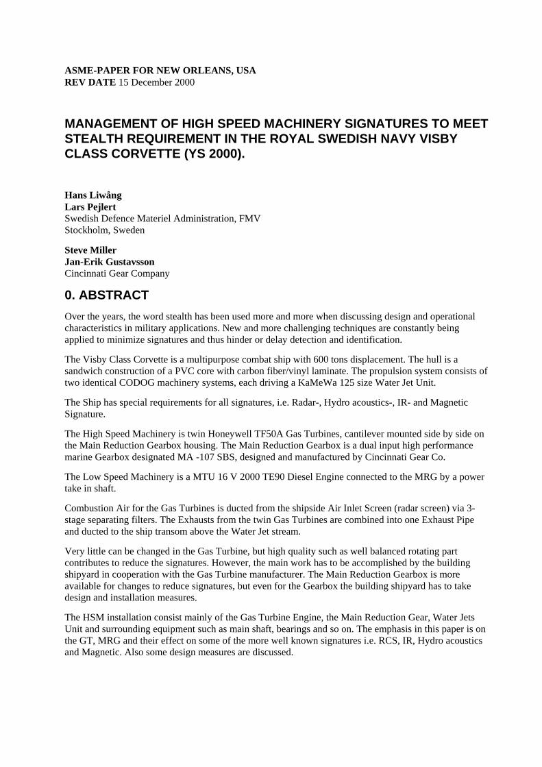
1. VISBY CLASS CORVETTE Six Visby class corvettes have been ordered by FMV for the Royal Swedish Navy from Kockum Naval Systems, KNS. The first of its class, HMS Visby was launched in June 2000 and the commissioning trials starts spring 2001.
FIGURE 1. Visby class Corvette
1.1. MAIN DATA
The Visby class corvette main data are as follows:
Length over all: Approx. 72 m Length between perpendiculars: 61,5 m Width: Max. 10,4 m Displacement, fully equipped: Approx. 600 tons Draught: Approx. 2,5 m Crew: 43 Hull: CFRP-sandwich High speed machinery: 4 Gas Turbines, total approx. 16 000 kW Low speed machinery: 2 Diesel Engines, total approx. 2 600 kW Propulsion: 2 Water Jet Propulsion units Generators: 3 Generators, total approx. 810 kW
2
1.2. SHIP MISSIONS
The multirole Visby class corvette ships can carry out a range of missions:
- Mine Counter Measures (MCM) - Anti Submarine Warfare (ASW) - Mine Laying - Surface Combat - Underwater Defence - Air Defence - Patrol service and escort duties
1.3. PROPULSION MACHINERY
The Propulsion Machinery for the Visby Class is of Combined Diesel or Gas Turbine (CODOG) type and consists of the following main components:
- 2 x Diesel Engines MTU 16 V 2000 TN90 (Low Speed Machinery, LSM) - 4 x Gas Turbines Honeywell TF50A (High Speed Machinery, HSM) - 2 x Main Reduction Gears (MRG) Cincinnati Gear MA-107 SBS - 2 x Water Jet Units (WJU) KaMeWa 125S-2
The CODOG Machinery allows speed up to 15 knots for long periods with the Low Speed Machinery and a top speed of more than 35 knots with the High Speed Machinery.
The HSM installation consist mainly of the Gas Turbine Engine, the Main Reduction Gear, Water Jet Unit and surrounding equipment such as main shaft, bearings and so on. The emphasis in this paper is put on the gas turbine, MRG and their effect on some of the better known signatures i.e. RCS, IR, Hydro acoustics and Magnetic. Also some design measures are discussed.
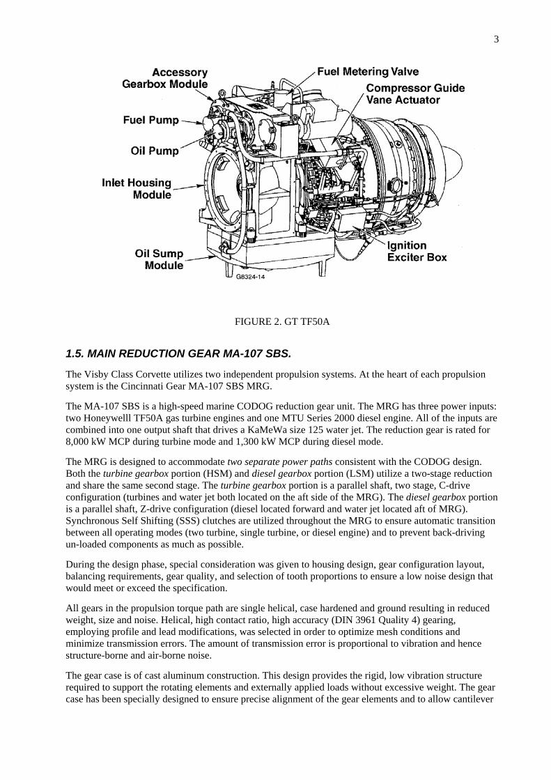
1.4. GAS TURBINE TF50A
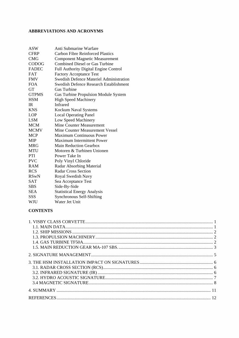
The Gas Turbine Engine, Honeywell TF50A is a two-shaft engine rated at 4000 kW maximum continuous power (MCP) and 4200 kW maximum intermittent power (MIP).
The Engine modules are: Inlet Housing, Oil Sump, Accessory Gearbox, Gas Producer Module and Combustor Module. The Gas Turbine is digital controlled by a Full Authority Digital Engine Control (FADEC) and the Gas Turbine Propulsion Module System (GTPMS) is controlled/monitored by the Local Operating Panel (LOP).
3
FIGURE 2. GT TF50A
1.5. MAIN REDUCTION GEAR MA-107 SBS.
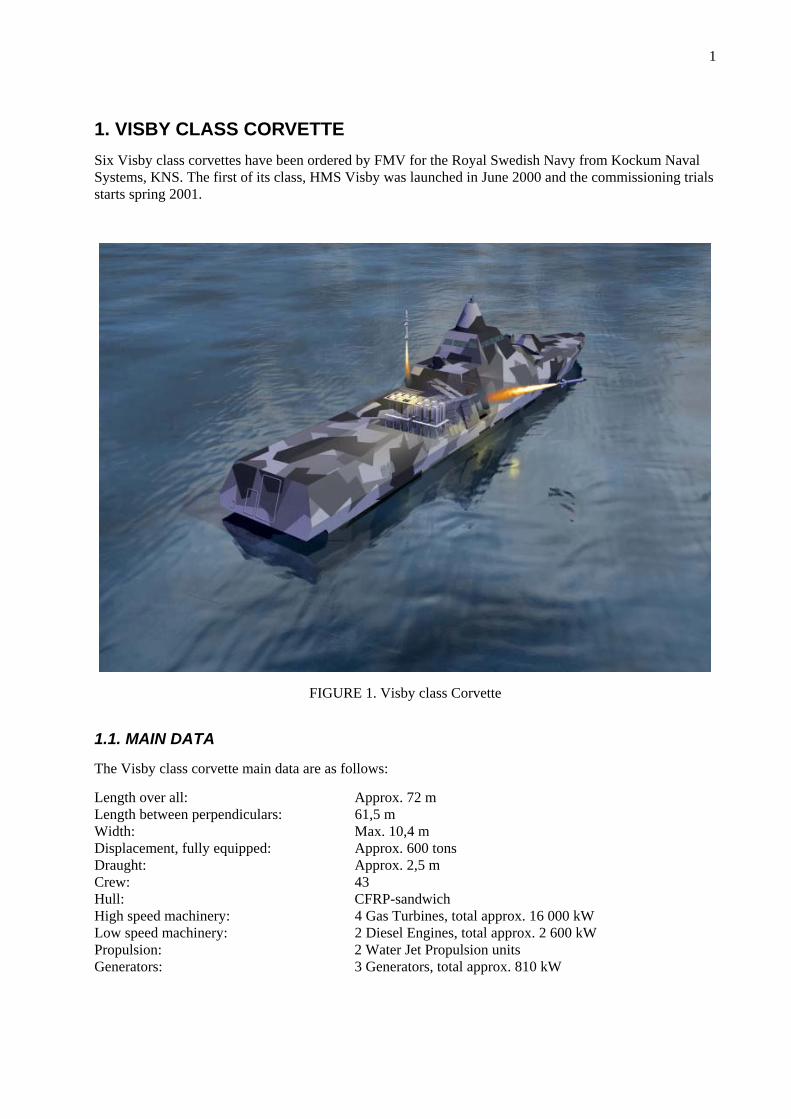
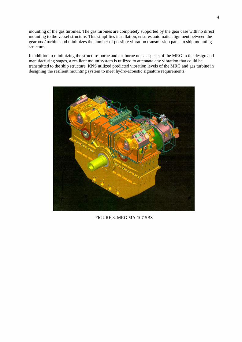
The Visby Class Corvette utilizes two independent propulsion systems. At the heart of each propulsion system is the Cincinnati Gear MA-107 SBS MRG.
The MA-107 SBS is a high-speed marine CODOG reduction gear unit. The MRG has three power inputs: two Honeywelll TF50A gas turbine engines and one MTU Series 2000 diesel engine. All of the inputs are combined into one output shaft that drives a KaMeWa size 125 water jet. The reduction gear is rated for 8,000 kW MCP during turbine mode and 1,300 kW MCP during diesel mode.
The MRG is designed to accommodate two separate power paths consistent with the CODOG design. Both the turbine gearbox portion (HSM) and diesel gearbox portion (LSM) utilize a two-stage reduction and share the same second stage. The turbine gearbox portion is a parallel shaft, two stage, C-drive configuration (turbines and water jet both located on the aft side of the MRG). The diesel gearbox portion is a parallel shaft, Z-drive configuration (diesel located forward and water jet located aft of MRG). Synchronous Self Shifting (SSS) clutches are utilized throughout the MRG to ensure automatic transition between all operating modes (two turbine, single turbine, or diesel engine) and to prevent back-driving un-loaded components as much as possible.
During the design phase, special consideration was given to housing design, gear configuration layout, balancing requirements, gear quality, and selection of tooth proportions to ensure a low noise design that would meet or exceed the specification.
All gears in the propulsion torque path are single helical, case hardened and ground resulting in reduced weight, size and noise. Helical, high contact ratio, high accuracy (DIN 3961 Quality 4) gearing, employing profile and lead modifications, was selected in order to optimize mesh conditions and minimize transmission errors. The amount of transmission error is proportional to vibration and hence structure-borne and air-borne noise.
The gear case is of cast aluminum construction. This design provides the rigid, low vibration structure required to support the rotating elements and externally applied loads without excessive weight. The gear case has been specially designed to ensure precise alignment of the gear elements and to allow cantilever
4
mounting of the gas turbines. The gas turbines are completely supported by the gear case with no direct mounting to the vessel structure. This simplifies installation, ensures automatic alignment between the gearbox / turbine and minimizes the number of possible vibration transmission paths to ship mounting structure.
In addition to minimizing the structure-borne and air-borne noise aspects of the MRG in the design and manufacturing stages, a resilient mount system is utilized to attenuate any vibration that could be transmitted to the ship structure. KNS utilized predicted vibration levels of the MRG and gas turbine in designing the resilient mounting system to meet hydro-acoustic signature requirements.
FIGURE 3. MRG MA-107 SBS
5
2. SIGNATURE MANAGEMENT
FMV received the ship signature requirements from the Armed Forces Headquarter by the ”Tactical - Technical - Economical - Target Schedule”.
FMV transformed the signatures levels to goals or requirements together with design-recommendations into the Design - Specification for the Ship Contract with the appointed shipyard, KNS.
KNS thereafter incorporate the signature requirements in the Technical Specifications for the contracts with the various sub-contractors.
Early in the project, working-groups for different signatures and systems onboard were established. Participants in the groups are personnel from FMV, KNS, FOA, RSwN and special consultants.
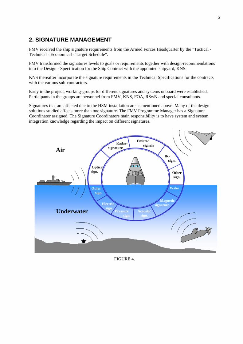
Signatures that are affected due to the HSM installation are as mentioned above. Many of the design solutions studied affects more than one signature. The FMV Programme Manager has a Signature Coordinator assigned. The Signature Coordinators main responsibility is to have system and system integration knowledge regarding the impact on different signatures.
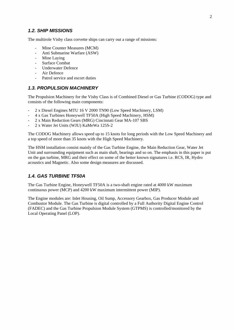
Optical sign.
IR- sign.
Emitted signals
Acoustic sign.
Magnetic signature
Pressure sign.
Electric sign.
Other sign.
Wake
Radar-signature Air
Underwater
Other sign.
FIGURE 4.
6
3. THE HSM INSTALLATION IMPACT ON SIGNATURES
All of the missions mentioned above have their specific signature requirements. This, in combination with the actual signatures affected by the HSM, gives input to the design. The missions, where HSM are involved will of course have the largest impact on the signature requirements for those particular missions.
3.1. RADAR CROSS SECTION (RCS)
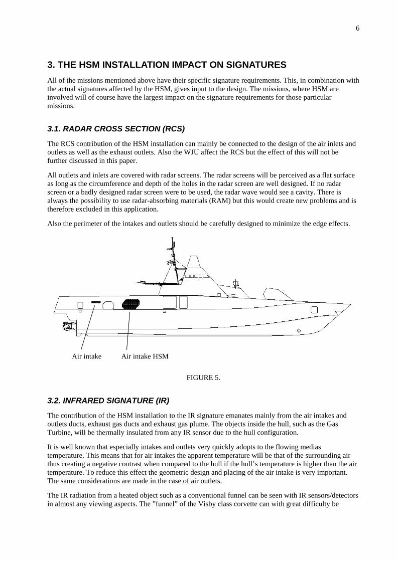
The RCS contribution of the HSM installation can mainly be connected to the design of the air inlets and outlets as well as the exhaust outlets. Also the WJU affect the RCS but the effect of this will not be further discussed in this paper.
All outlets and inlets are covered with radar screens. The radar screens will be perceived as a flat surface as long as the circumference and depth of the holes in the radar screen are well designed. If no radar screen or a badly designed radar screen were to be used, the radar wave would see a cavity. There is always the possibility to use radar-absorbing materials (RAM) but this would create new problems and is therefore excluded in this application.
Also the perimeter of the intakes and outlets should be carefully designed to minimize the edge effects.
Air intake Air intake HSM
FIGURE 5.
3.2. INFRARED SIGNATURE (IR)
The contribution of the HSM installation to the IR signature emanates mainly from the air intakes and outlets ducts, exhaust gas ducts and exhaust gas plume. The objects inside the hull, such as the Gas Turbine, will be thermally insulated from any IR sensor due to the hull configuration.
It is well known that especially intakes and outlets very quickly adopts to the flowing medias temperature. This means that for air intakes the apparent temperature will be that of the surrounding air thus creating a negative contrast when compared to the hull if the hull’s temperature is higher than the air temperature. To reduce this effect the geometric design and placing of the air intake is very important. The same considerations are made in the case of air outlets.
The IR radiation from a heated object such as a conventional funnel can be seen with IR sensors/detectors in almost any viewing aspects. The ”funnel” of the Visby class corvette can with great difficulty be
7
detected due to the placing of the exhaust gas discharge. The discharge of the exhaust gas close to the water surface in combination with the fact that it is almost impossible to see any warm surfaces will give very low IR radiation from this installation.
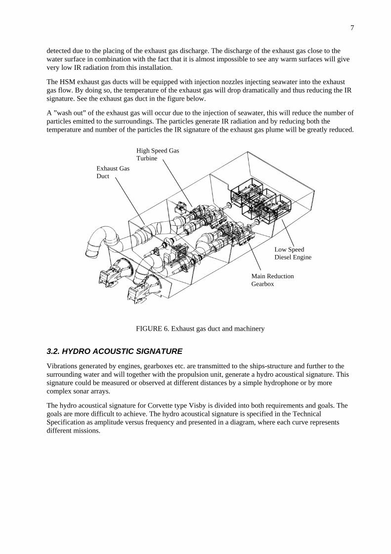
The HSM exhaust gas ducts will be equipped with injection nozzles injecting seawater into the exhaust gas flow. By doing so, the temperature of the exhaust gas will drop dramatically and thus reducing the IR signature. See the exhaust gas duct in the figure below.
A ”wash out” of the exhaust gas will occur due to the injection of seawater, this will reduce the number of particles emitted to the surroundings. The particles generate IR radiation and by reducing both the temperature and number of the particles the IR signature of the exhaust gas plume will be greatly reduced.
Low Speed Diesel Engine
Main Reduction Gearbox
High Speed Gas Turbine
Exhaust Gas Duct
FIGURE 6. Exhaust gas duct and machinery
3.2. HYDRO ACOUSTIC SIGNATURE
Vibrations generated by engines, gearboxes etc. are transmitted to the ships-structure and further to the surrounding water and will together with the propulsion unit, generate a hydro acoustical signature. This signature could be measured or observed at different distances by a simple hydrophone or by more complex sonar arrays.
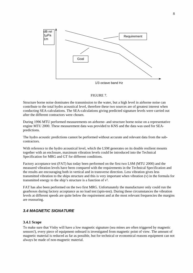
The hydro acoustical signature for Corvette type Visby is divided into both requirements and goals. The goals are more difficult to achieve. The hydro acoustical signature is specified in the Technical Specification as amplitude versus frequency and presented in a diagram, where each curve represents different missions.
8
dB rel 1µPa 1m
1/3 octave band Hz
Goal
Requirement
FIGURE 7.
Structure borne noise dominates the transmission to the water, but a high level in airborne noise can contribute to the total hydro acoustical level, therefore these two sources are of greatest interest when conducting SEA-calculations. The SEA-calculations giving predicted signature levels were carried out after the different contractors were chosen.
During 1996 MTU performed measurements on airborne- and structure borne noise on a representative engine MTU 2000. These measurement data was provided to KNS and the data was used for SEA-predictions.
The hydro acoustic predictions cannot be performed without accurate and relevant data from the sub-contractors.
With reference to the hydro acoustical level, which the LSM generates on its double resilient mounts together with an enclosure, maximum vibration levels could be introduced into the Technical Specification for MRG and GT for different conditions.
Factory acceptance test (FAT) has today been performed on the first two LSM (MTU 2000) and the measured vibration levels have been compared with the requirements in the Technical Specification and the results are encouraging both in vertical and in transverse direction. Less vibration gives less transmitted vibration to the ships structure and this is very important when vibration (v) in the formula for transmitted energy to the ship’s structure is a function of v².
FAT has also been performed on the two first MRG. Unfortunately the manufacturer only could run the gearboxes during factory acceptance as no load test (spin-test). During these circumstances the vibration levels at different speeds are quite below the requirement and at the most relevant frequencies the margins are reassuring.
3.4 MAGNETIC SIGNATURE
3.4.1 Scope To make sure that Visby will have a low magnetic signature (sea mines are often triggered by magnetic sensors!), every piece of equipment onboard is investigated from magnetic point of view. The amount of magnetic material is reduced as far as possible, but for technical or economical reasons equipment can not always be made of non-magnetic material.
9
For the MRG, the ferromagnetic gearwheels are the main magnetic sources. Furthermore, since the wheels are turning in several different speeds, they may all become transducers of magnetic ”radiation” if they are magnetised.
The gas turbines are from magnetic point of view rather ”harmless” to the overall signature of the vessel and no changes have been made to alter their design due to magnetic requirements.
3.4.2. Ferromagnetic fields The magnetic field from an object is consisting of two parts, induced and permanent. The induced part is always proportional to, and aligned with, the field surrounding the object. The permanent part is a residual magnetism that acts as a ”magnetic memory”. This part may be several times higher than the induced part and it may have any direction in the object.
A process called Deperming where the small magnetic ”cells” in the iron are forced to counteract each other may reduce the permanent magnetisation. For the MRG, Cincinnati Gear Company had to build a new Deperming plant since their standard Deperming equipment was not sufficient for fulfilling the FMV requirements. The requirement in this case was a certain maximum ratio between permanent and induced magnetisation.
As mentioned above, the induced magnetisation is dependant of the surrounding earth’s magnetic field. By changing the field around the object with ”electromagnets” it is possible to find a setting where the magnetic field from the object and the field from the coils around will be in balance.
Since a ship can move to different locations, in different headings and with different pitch and roll the earth’s magnetic field may ”hit” the object in any angle. For that reason it is necessary to have a three-dimensional coil system on every major object onboard. The current in the coils must furthermore be updated several times per second to keep the best compensation due to ship movements.
One MRG, two gas turbines and the auxiliary equipment attached to them are from magnetic point of view seen as one unit. The coil design for each such unit is rather complex due to a lot of practical circumstances. The coil cables must not interfere with hull structure, moving parts, hot parts or service points. On top of that they must be in the best possible ”magnetic” position.
3.4.3. Degaussing System When the MRG´s arrive to Sweden they will be brought to a magnetic land range Component Magnetic Measurement (CMG) where the coil system will be tested and tuned.
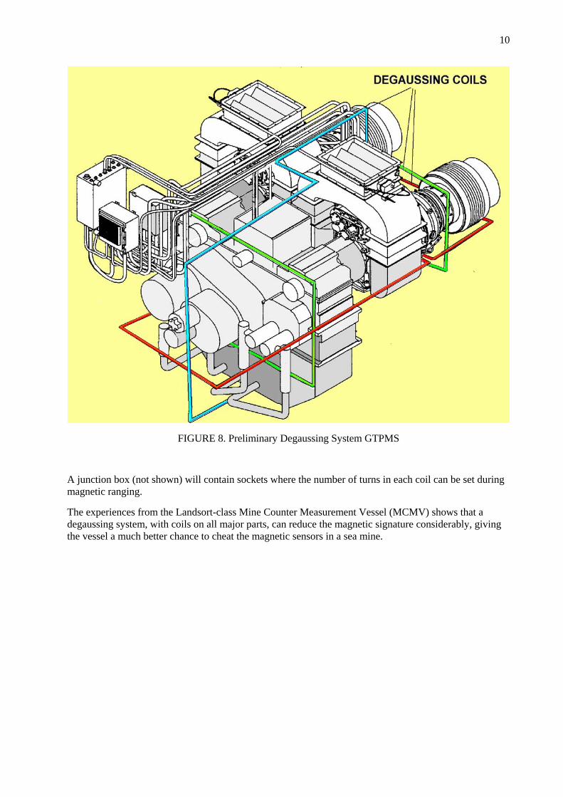
The figure below shows the preliminary design of the degaussing coils for the MRG and the gas turbines. The red, blue and green coloured cables can, with the right setting and current, compensate for magnetisation in any direction.
10
FIGURE 8. Preliminary Degaussing System GTPMS
A junction box (not shown) will contain sockets where the number of turns in each coil can be set during magnetic ranging.
The experiences from the Landsort-class Mine Counter Measurement Vessel (MCMV) shows that a degaussing system, with coils on all major parts, can reduce the magnetic signature considerably, giving the vessel a much better chance to cheat the magnetic sensors in a sea mine.
11
4. SUMMARY
The signature management work to reduce the signatures from the HSM is carried out by all contractors in all phases as:
- Project work - Design work - Manufacturing - Installation of components in the ship - Sea Acceptance Test (SAT)
Different ship signature requirements have been transformed to measurable limits for the HSM components.
At SAT and forthcoming ship system tests all signatures will be measured to verify and secure the ship requirements.
After delivery of the ships to the Navy, the crew carries out signature management and signature work.
During the ship life-time (25 years) the signature work is involved in all maintenance- and repair work.
All efforts described in this paper, reveal that the Visby class ships HSM will have lower signature levels, than earlier ships in the RSwN.
All parties involved have increased their knowledge and in some cases improved equipment and products.
Other bonuses are lower exhaust emissions, lower noise levels, etc. and some of the signature work can be a benefit for other military or civilian HSM applications.

12
REFERENCES 1. ASME PAPER No 98-GT-437, “A 21:st CENTURY WARSHIP WITH A 21:st
CENTURY PROPULSION SYSTEM”
2. IMEC 94, Paper 7, “Signature management as an integral part of new warship design”