Embed Size (px)
Citation preview
MANAGEMENT OF MATERIALS HANDLING EQUIPMENT (MHE) AND SHIPBOARD MOBILE SUPPORT EQUIPMENT (SMSE)
DEPARTMENT OF THE NAVY NAVAL SUPPLY SYSTEMS COMMAND
WEAPON SYSTEMS SUPPORT 5450 CARLISLE PIKE
P.O. BOX 2020 MECHANICSBURG, PA 17055-0791
This publication is issued as information and guidance for all personnel of forces afloat and ashore activities having direct or related responsibilities for the management of Materials Handling Equipment (MHE)/Shipboard Mobile Support Equipment (SMSE) and is in accordance with the basic policies and responsibilities assigned by the Secretary of the Navy. It supersedes NAVSUP Publication 538 Fifth Revision of 1 July 2010.
This publication has been revised to include updated maintenance procedures for MHE/SMSE and to document all Navy regulations and procedures relating to the overall management of this equipment. NAVSUP Publication 538 Revision Six has been reviewed and approved.
Commander, Naval Supply Systems Command (COMNAVSUPSYSCOM) is the Navy's single manager for Material Handling Equipment (MHE) and further delegates MHE Program responsibilities to NAVSUP Weapon Systems Support (WSS) for execution.
Enclosure (1) documents the abstract of significant changes supporting this Sixth Revision.

ABSTRACT OF SIGNIFICANT CHANGES
1. Changes the following Command names throughout this publication: (a) Naval Inventory Control Point - Mechanicsburg (NAVICP-M) to Naval Supply System Command, Weapons Systems Support (NAVSUP WSS); (b) Fleet and Industrial Supply Center (FISC) to NAVSUP Fleet Logistics Center (NAVSUP FLC); and (c) the Naval PHST Center at Earle, NJ to the Naval PHST Center at Picatinny Arsenal, NJ.
2. Illustrates latest Medical Examiner's Certificate (OPNAV 8020/2 Form), figure 4-1.
3. Provides weight testing direction in paragraph 8-7 for MHE following maintenance operations or repairs for deployed ships.
4. Introduces a note in paragraphs 8-7.3 and 8-7.4 requiring all ashore forklift trucks and ashore powered pallet trucks, respectively, that require operational weight testing to comply with the overload weight testing requirements documented in NAVSEA SW023-AH-WHM-010.
5. Requires that all personnel who operate the Power/Pressure Washer (Model No. QRE-3001A) are qualified under the revised provisions of paragraph 12-3.2. This requires that operators satisfactorily complete the training course documented in appendix G. Additionally, operators must be issued and possess a valid MHE Operator's License, in accordance with revised figure 4-2 and new MHE Class Definition added in table 4-1.
Enclosure (1)
NAVSUP PUBLICATION 5380530-LP-642-6711 SIXTH REVISION
MANAGEMENT OF
MATERIALS HANDLING EQUIPMENT (MHE)
AND SHIPBOARD MOBILE SUPPORT EQUIPMENT (SMSE)
DISTRIBUTION STATEMENT AApproved for Public Release; Distribution is Unlimited
THIS PUBLICATION SUPERSEDES NAVSUP PUBLICATION 538 FIFTH REVISION
DATED 1 JULY 2010
PUBLISHED BY DIRECTION OF COMMANDER, NAVAL SUPPLY SYSTEMS COMMAND

This page left intentionally blank

NAVSUP PUBLICATION 538
0530-LP-642-6711 SIXTH REVISION
MANAGEMENT OF
MATERIALS HANDLING EQUIPMENT (MHE)
AND SHIPBOARD MOBILE SUPPORT EQUIPMENT (SMSE)
DISTRIBUTION STATEMENT AApproved for Public Release; Distribution is Unlimited
THIS PUBLICATION SUPERSEDES NAVSUP PUBLICATION 538 FIFTH REVISION
DATED 1 JULY 2010
PUBLISHED BY DIRECTION OF COMMANDER, NAVAL SUPPLY SYSTEMS COMMAND
1 APRIL 2012

NAVSUP PUBLICATION 538 SIXTH REVISION
A
Reproduction for nonmilitary use of the information or illustrations contained in this publication is not permitted. This does not preclude reproduction and use of any part of this manual by contracted agencies responsible for the training and instruction of personnel who handle and transport general supply materials or hazardous materials (other than ammunition and explosives). The policy for military use reproduction is established for the Army in AR 380-5, for the Navy and Marine Corps in SECNAVINST 5510.36 (series), and for the Air Force in Air Force Regulations 205-1.
LIST OF EFFECTIVE PAGES
The total number of pages in this manual is 344. They are all original Revision Six pages, with the new changes identified by change bars along the margin. The date of issue for all pages in this manual is 1 April 2012.
NAVSUP PUBLICATION 538 SIXTH REVISION
Foreword-1/(Foreword-2 Blank)
FOREWORD
1. This publication documents the management, maintenance, and safe use of industrial Materials Handling Equipment (MHE) and their approved attachments, and Shipboard Mobile Support Equipment (SMSE) at U.S. Navy units ashore and afloat. Additionally, as part of this publication, a supplement containing the Navy known repair time standards (by section according to the equipment cost code) and actual industrial MHE manufacturers repair time standards appear as an individual file on this DVD entitled, "Repair Time Standards Supplement".
2. This publication is not intended to supersede, contravene, or modify any federal, state, municipal or local laws and their supplements. If any provision of this publication appears to conflict with any other published regulation this fact should be reported to Commander, NAVSUP Weapon Systems Support (NAVSUP WSS) [formerly Naval Inventory Control Point (NAVICP)], 5450 Carlisle Pike, Code 8341, P.O. Box 2020, Mechanicsburg, PA 17055-0788.
3. Copies of this publication may be obtained as described in paragraph 1-15.
4. This publication supersedes NAVSUP Publication 538 Fifth Revision dated 1 July 2010, which should be destroyed. Changes to this publication will be issued as required. Comments or suggestions relative to material to be included in such changes should be forwarded as specified in paragraph 1-14.

This page left intentionally blank
NAVSUP PUBLICATION 538 SIXTH REVISION
TABLE OF CONTENTS
Chapter/Paragraph Page
i
1 INTRODUCTION . . . . . . . . . . . . . . . . . . . . . . . . . . . . . . . . . . . . . . . . . . . . . . . . . . . . . 1-11-1 Purpose . . . . . . . . . . . . . . . . . . . . . . . . . . . . . . . . . . . . . . . . . . . . . . . . . . . . . . . . 1-11-2 Scope . . . . . . . . . . . . . . . . . . . . . . . . . . . . . . . . . . . . . . . . . . . . . . . . . . . . . . . . . 1-11-3 Cancellation . . . . . . . . . . . . . . . . . . . . . . . . . . . . . . . . . . . . . . . . . . . . . . . . . . . . 1-11-4 Organization of Publication . . . . . . . . . . . . . . . . . . . . . . . . . . . . . . . . . . . . . . . . 1-11-5 Repair Time Standards Supplement . . . . . . . . . . . . . . . . . . . . . . . . . . . . . . . . . . 1-21-6 Reference Documents . . . . . . . . . . . . . . . . . . . . . . . . . . . . . . . . . . . . . . . . . . . . 1-21-7 MHE Operator Training Course . . . . . . . . . . . . . . . . . . . . . . . . . . . . . . . . . . . . 1-21-8 Materials Handling Equipment (MHE) Assist Checklist . . . . . . . . . . . . . . . . . 1-21-9 Shipment and Transportation of MHE . . . . . . . . . . . . . . . . . . . . . . . . . . . . . . . . 1-21-10 Emergency Reclamation Procedures . . . . . . . . . . . . . . . . . . . . . . . . . . . . . . . . . 1-31-11 Deck Scrubber Operator’s Training Course . . . . . . . . . . . . . . . . . . . . . . . . . . . . 1-31-12 QRE-3001A Power/Pressure Washer Operator’s Training Course . . . . . . . . . . 1-31-13 Terms and Definitions . . . . . . . . . . . . . . . . . . . . . . . . . . . . . . . . . . . . . . . . . . . . 1-31-13.1 A-4 Condition . . . . . . . . . . . . . . . . . . . . . . . . . . . . . . . . . . . . . . . . . . . . . . . . . . 1-31-13.2 Accumulated Repair Expenditure Limits . . . . . . . . . . . . . . . . . . . . . . . . . . . . . 1-31-13.3 Commanding Officer/Officer-In-Charge (CO/OIC) . . . . . . . . . . . . . . . . . . . . . 1-31-13.4 Equipment Management and Control System (EMACS) . . . . . . . . . . . . . . . . . 1-31-13.5 Materials Handling Equipment (MHE) . . . . . . . . . . . . . . . . . . . . . . . . . . . . . . . 1-41-13.6 One-Time Repair . . . . . . . . . . . . . . . . . . . . . . . . . . . . . . . . . . . . . . . . . . . . . . . . 1-41-13.7 Preventive Maintenance . . . . . . . . . . . . . . . . . . . . . . . . . . . . . . . . . . . . . . . . . . . 1-41-13.8 Repair . . . . . . . . . . . . . . . . . . . . . . . . . . . . . . . . . . . . . . . . . . . . . . . . . . . . . . . . . 1-41-13.9 Service Life Extension Program (SLEP) . . . . . . . . . . . . . . . . . . . . . . . . . . . . . . 1-41-14 Reporting Conflicts, Errors and Omissions in Publication . . . . . . . . . . . . . . . . 1-41-15 Obtaining Copies of This Publication . . . . . . . . . . . . . . . . . . . . . . . . . . . . . . . . 1-41-15.1 Hard Copies . . . . . . . . . . . . . . . . . . . . . . . . . . . . . . . . . . . . . . . . . . . . . . . . . . . . 1-41-15.2 DVD Copies . . . . . . . . . . . . . . . . . . . . . . . . . . . . . . . . . . . . . . . . . . . . . . . . . . . . 1-51-16 Distribution of Publication . . . . . . . . . . . . . . . . . . . . . . . . . . . . . . . . . . . . . . . . . 1-51-17 Date of Publication . . . . . . . . . . . . . . . . . . . . . . . . . . . . . . . . . . . . . . . . . . . . . . 1-5
2 ADMINISTRATION . . . . . . . . . . . . . . . . . . . . . . . . . . . . . . . . . . . . . . . . . . . . . . . . . . . 2-12-1 Authority . . . . . . . . . . . . . . . . . . . . . . . . . . . . . . . . . . . . . . . . . . . . . . . . . . . . . . 2-12-2 Program Responsibilities . . . . . . . . . . . . . . . . . . . . . . . . . . . . . . . . . . . . . . . . . . 2-12-2.1 Program Manager . . . . . . . . . . . . . . . . . . . . . . . . . . . . . . . . . . . . . . . . . . . . . . . 2-12-2.2 Life Cycle Manager . . . . . . . . . . . . . . . . . . . . . . . . . . . . . . . . . . . . . . . . . . . . . . 2-22-2.3 In-Service Engineering Agent (ISEA) . . . . . . . . . . . . . . . . . . . . . . . . . . . . . . . . 2-42-2.4 NAVAIR/NAVSEA/NAVFAC Systems Command . . . . . . . . . . . . . . . . . . . . . . 2-52-2.5 Regional Manager . . . . . . . . . . . . . . . . . . . . . . . . . . . . . . . . . . . . . . . . . . . . . . . 2-62-2.6 Major Claimant . . . . . . . . . . . . . . . . . . . . . . . . . . . . . . . . . . . . . . . . . . . . . . . . . 2-82-2.7 Type Commander (TYCOM) . . . . . . . . . . . . . . . . . . . . . . . . . . . . . . . . . . . . . . . 2-82-2.8 Navy Users . . . . . . . . . . . . . . . . . . . . . . . . . . . . . . . . . . . . . . . . . . . . . . . . . . . . . 2-92-2.8.1 Ashore . . . . . . . . . . . . . . . . . . . . . . . . . . . . . . . . . . . . . . . . . . . . . . . . . . . . . . . . . 2-92-2.8.2 Afloat . . . . . . . . . . . . . . . . . . . . . . . . . . . . . . . . . . . . . . . . . . . . . . . . . . . . . . . . 2-102-3 MHE Assignment . . . . . . . . . . . . . . . . . . . . . . . . . . . . . . . . . . . . . . . . . . . . . . 2-10
ii
NAVSUP PUBLICATION 538 SIXTH REVISION
TABLE OF CONTENTS (Continued)
Chapter/Paragraph Page
2-3.1 General Criteria . . . . . . . . . . . . . . . . . . . . . . . . . . . . . . . . . . . . . . . . . . . . . . . . 2-102-3.2 Allowance Deficiencies . . . . . . . . . . . . . . . . . . . . . . . . . . . . . . . . . . . . . . . . . . 2-112-3.3 Allowance Changes . . . . . . . . . . . . . . . . . . . . . . . . . . . . . . . . . . . . . . . . . . . . . 2-112-3.4 User Requests for MHE and SMSE. . . . . . . . . . . . . . . . . . . . . . . . . . . . . . . . . 2-122-3.4.1 Other Procurement Navy (OPN) Funded Activities . . . . . . . . . . . . . . . . . . . . . 2-122-3.4.2 Navy Working Capital Funded (NWCF) Activities . . . . . . . . . . . . . . . . . . . . . 2-122-3.5 Other Requirements . . . . . . . . . . . . . . . . . . . . . . . . . . . . . . . . . . . . . . . . . . . . . 2-152-4 New or SLEP Equipment . . . . . . . . . . . . . . . . . . . . . . . . . . . . . . . . . . . . . . . . . 2-152-5 Replacement Units . . . . . . . . . . . . . . . . . . . . . . . . . . . . . . . . . . . . . . . . . . . . . . 2-152-5.1 Similar Units . . . . . . . . . . . . . . . . . . . . . . . . . . . . . . . . . . . . . . . . . . . . . . . . . . 2-152-5.2 Non-Identical Units . . . . . . . . . . . . . . . . . . . . . . . . . . . . . . . . . . . . . . . . . . . . . 2-152-5.3 Cannibalization . . . . . . . . . . . . . . . . . . . . . . . . . . . . . . . . . . . . . . . . . . . . . . . . 2-152-5.4 NWCF Funding . . . . . . . . . . . . . . . . . . . . . . . . . . . . . . . . . . . . . . . . . . . . . . . . 2-162-6 Rental/Leasing of Operating Equipment . . . . . . . . . . . . . . . . . . . . . . . . . . . . . 2-162-6.1 OPN Funded Activities . . . . . . . . . . . . . . . . . . . . . . . . . . . . . . . . . . . . . . . . . . 2-162-6.2 NWCF and Special Funded Program Activities . . . . . . . . . . . . . . . . . . . . . . . 2-192-6.3 NAVSUP FLC Regional Manager Leasing Guidelines . . . . . . . . . . . . . . . . . . 2-192-7 Modifications or Alterations . . . . . . . . . . . . . . . . . . . . . . . . . . . . . . . . . . . . . . 2-202-8 Cannibalization . . . . . . . . . . . . . . . . . . . . . . . . . . . . . . . . . . . . . . . . . . . . . . . . 2-202-8.1 NAVSUP FLC Regional Manager . . . . . . . . . . . . . . . . . . . . . . . . . . . . . . . . . . 2-202-8.2 Afloat . . . . . . . . . . . . . . . . . . . . . . . . . . . . . . . . . . . . . . . . . . . . . . . . . . . . . . . . 2-202-9 U.S. Navy (USN) Registration Numbers . . . . . . . . . . . . . . . . . . . . . . . . . . . . . 2-212-10 Budgeting and Funding . . . . . . . . . . . . . . . . . . . . . . . . . . . . . . . . . . . . . . . . . . 2-222-10.1 Investment . . . . . . . . . . . . . . . . . . . . . . . . . . . . . . . . . . . . . . . . . . . . . . . . . . . . 2-222-10.2 Expense . . . . . . . . . . . . . . . . . . . . . . . . . . . . . . . . . . . . . . . . . . . . . . . . . . . . . . 2-222-10.3 Specific Circumstances . . . . . . . . . . . . . . . . . . . . . . . . . . . . . . . . . . . . . . . . . . 2-222-11 Disposition of Excess and Disposal of MHE/SMSE . . . . . . . . . . . . . . . . . . . . 2-222-11.1 Excess Turn-In Procedures . . . . . . . . . . . . . . . . . . . . . . . . . . . . . . . . . . . . . . . 2-242-11.2 Disposal Procedures. . . . . . . . . . . . . . . . . . . . . . . . . . . . . . . . . . . . . . . . . . . . . 2-24
3 TYPES OF INDUSTRIAL MATERIALS HANDLING EQUIPMENT . . . . . . . . . . . . . . 3-13-1 General . . . . . . . . . . . . . . . . . . . . . . . . . . . . . . . . . . . . . . . . . . . . . . . . . . . . . . . . 3-13-1.1 National Fire Protection Association (NFPA) Designations . . . . . . . . . . . . . . . 3-13-1.2 Naval Designations . . . . . . . . . . . . . . . . . . . . . . . . . . . . . . . . . . . . . . . . . . . . . . 3-23-1.2.1 Manual Pallet Trucks (Afloat) . . . . . . . . . . . . . . . . . . . . . . . . . . . . . . . . . . . . . . 3-23-1.2.2 Manual Pallet Trucks (Ashore) . . . . . . . . . . . . . . . . . . . . . . . . . . . . . . . . . . . . . . 3-23-1.3 Non-Designations . . . . . . . . . . . . . . . . . . . . . . . . . . . . . . . . . . . . . . . . . . . . . . . 3-23-1.3.1 Mobile Cargo Cranes. . . . . . . . . . . . . . . . . . . . . . . . . . . . . . . . . . . . . . . . . . . . . . 3-23-1.3.2 Aerial Work Platforms. . . . . . . . . . . . . . . . . . . . . . . . . . . . . . . . . . . . . . . . . . . . . 3-33-1.3.3 Diesel Conveyor Belt Vehicles. . . . . . . . . . . . . . . . . . . . . . . . . . . . . . . . . . . . . . 3-33-2 Forklift Trucks . . . . . . . . . . . . . . . . . . . . . . . . . . . . . . . . . . . . . . . . . . . . . . . . . . 3-33-2.1 Standard Forklift Trucks . . . . . . . . . . . . . . . . . . . . . . . . . . . . . . . . . . . . . . . . . . 3-33-2.2 Reaching and Tiering . . . . . . . . . . . . . . . . . . . . . . . . . . . . . . . . . . . . . . . . . . . . . 3-73-2.3 Sideloader . . . . . . . . . . . . . . . . . . . . . . . . . . . . . . . . . . . . . . . . . . . . . . . . . . . . . 3-83-2.4 Rough Terrain . . . . . . . . . . . . . . . . . . . . . . . . . . . . . . . . . . . . . . . . . . . . . . . . . . 3-9

NAVSUP PUBLICATION 538 SIXTH REVISION
TABLE OF CONTENTS (Continued)
Chapter/Paragraph Page
iii
3-2.5 Front/Sideloader (Swingmast) . . . . . . . . . . . . . . . . . . . . . . . . . . . . . . . . . . . . . . 3-93-3 Forklift Attachments . . . . . . . . . . . . . . . . . . . . . . . . . . . . . . . . . . . . . . . . . . . . 3-123-3.1 Fork Extensions. . . . . . . . . . . . . . . . . . . . . . . . . . . . . . . . . . . . . . . . . . . . . . . . 3-123-3.2 Fork Stops. . . . . . . . . . . . . . . . . . . . . . . . . . . . . . . . . . . . . . . . . . . . . . . . . . . . . 3-123-3.3 Personnel Baskets. . . . . . . . . . . . . . . . . . . . . . . . . . . . . . . . . . . . . . . . . . . . . . . 3-123-3.4 Salvage Platforms. . . . . . . . . . . . . . . . . . . . . . . . . . . . . . . . . . . . . . . . . . . . . . . 3-123-4 Straddle Carriers . . . . . . . . . . . . . . . . . . . . . . . . . . . . . . . . . . . . . . . . . . . . . . . 3-133-5 Pallet Trucks . . . . . . . . . . . . . . . . . . . . . . . . . . . . . . . . . . . . . . . . . . . . . . . . . . 3-133-5.1 Electric-Powered Rider-Type . . . . . . . . . . . . . . . . . . . . . . . . . . . . . . . . . . . . . . 3-133-5.2 Electric-Powered Walkie-Type . . . . . . . . . . . . . . . . . . . . . . . . . . . . . . . . . . . . 3-173-5.3 Manual Pallet Trucks . . . . . . . . . . . . . . . . . . . . . . . . . . . . . . . . . . . . . . . . . . . . 3-173-6 Platform Trucks . . . . . . . . . . . . . . . . . . . . . . . . . . . . . . . . . . . . . . . . . . . . . . . . 3-173-7 Tow Tractors . . . . . . . . . . . . . . . . . . . . . . . . . . . . . . . . . . . . . . . . . . . . . . . . . . 3-193-8 International Organization for Standardization (ISO)
Container Lift Trucks . . . . . . . . . . . . . . . . . . . . . . . . . . . . . . . . . . . . . . . . . . . . 3-193-9 Mobile Cargo Cranes . . . . . . . . . . . . . . . . . . . . . . . . . . . . . . . . . . . . . . . . . . . . 3-213-10 Shipboard Aerial Work Platforms . . . . . . . . . . . . . . . . . . . . . . . . . . . . . . . . . . 3-213-10.1 Boom-Lift Platform . . . . . . . . . . . . . . . . . . . . . . . . . . . . . . . . . . . . . . . . . . . . . 3-223-10.2 Scissor-Lift Platform . . . . . . . . . . . . . . . . . . . . . . . . . . . . . . . . . . . . . . . . . . . . 3-233-11 Diesel Conveyor Belt Vehicles . . . . . . . . . . . . . . . . . . . . . . . . . . . . . . . . . . . . 3-23
4 MATERIALS HANDLING EQUIPMENT LICENSING . . . . . . . . . . . . . . . . . . . . . . . . . 4-14-1 General . . . . . . . . . . . . . . . . . . . . . . . . . . . . . . . . . . . . . . . . . . . . . . . . . . . . . . . . 4-14-2 Avoidance of Duplicate Training . . . . . . . . . . . . . . . . . . . . . . . . . . . . . . . . . . . . 4-14-3 Qualifications . . . . . . . . . . . . . . . . . . . . . . . . . . . . . . . . . . . . . . . . . . . . . . . . . . . 4-14-3.1 Medical. . . . . . . . . . . . . . . . . . . . . . . . . . . . . . . . . . . . . . . . . . . . . . . . . . . . . . . . 4-14-3.2 Age. . . . . . . . . . . . . . . . . . . . . . . . . . . . . . . . . . . . . . . . . . . . . . . . . . . . . . . . . . . 4-24-3.3 Initial Operator Training. . . . . . . . . . . . . . . . . . . . . . . . . . . . . . . . . . . . . . . . . . . 4-24-3.4 Administrative Operator Training Controls. . . . . . . . . . . . . . . . . . . . . . . . . . . . 4-34-3.5 Refresher Operator Training . . . . . . . . . . . . . . . . . . . . . . . . . . . . . . . . . . . . . . . 4-34-3.6 Hazardous Materials (HAZMAT) Training . . . . . . . . . . . . . . . . . . . . . . . . . . . . 4-44-4 License . . . . . . . . . . . . . . . . . . . . . . . . . . . . . . . . . . . . . . . . . . . . . . . . . . . . . . . . 4-44-4.1 MHE Operator’s License . . . . . . . . . . . . . . . . . . . . . . . . . . . . . . . . . . . . . . . . . . 4-44-4.2 Issuance . . . . . . . . . . . . . . . . . . . . . . . . . . . . . . . . . . . . . . . . . . . . . . . . . . . . . . . 4-64-4.3 Evaluation . . . . . . . . . . . . . . . . . . . . . . . . . . . . . . . . . . . . . . . . . . . . . . . . . . . . . 4-64-4.4 Renewal . . . . . . . . . . . . . . . . . . . . . . . . . . . . . . . . . . . . . . . . . . . . . . . . . . . . . . . 4-64-4.5 Revocation . . . . . . . . . . . . . . . . . . . . . . . . . . . . . . . . . . . . . . . . . . . . . . . . . . . . . 4-64-5 Instructor Training . . . . . . . . . . . . . . . . . . . . . . . . . . . . . . . . . . . . . . . . . . . . . . . 4-6
5 OPERATIONAL SAFETY REQUIREMENTS . . . . . . . . . . . . . . . . . . . . . . . . . . . . . . . 5-15-1 General . . . . . . . . . . . . . . . . . . . . . . . . . . . . . . . . . . . . . . . . . . . . . . . . . . . . . . . . 5-15-2 Department of Defense (DOD) Occupational Safety and
Health (OSH) Program. . . . . . . . . . . . . . . . . . . . . . . . . . . . . . . . . . . . . . . . . . . . 5-1

iv
NAVSUP PUBLICATION 538 SIXTH REVISION
TABLE OF CONTENTS (Continued)
Chapter/Paragraph Page
5-3 General Safety Regulations . . . . . . . . . . . . . . . . . . . . . . . . . . . . . . . . . . . . . . . . 5-15-3.1 General Safety Precautions . . . . . . . . . . . . . . . . . . . . . . . . . . . . . . . . . . . . . . . . 5-15-3.1.1 Mobile Cargo Cranes. . . . . . . . . . . . . . . . . . . . . . . . . . . . . . . . . . . . . . . . . . . . . . 5-35-3.2 Personnel Safety . . . . . . . . . . . . . . . . . . . . . . . . . . . . . . . . . . . . . . . . . . . . . . . . 5-45-3.2.1 Mobile Cargo Cranes . . . . . . . . . . . . . . . . . . . . . . . . . . . . . . . . . . . . . . . . . . . . . 5-45-3.2.2 Aerial Work Platforms. . . . . . . . . . . . . . . . . . . . . . . . . . . . . . . . . . . . . . . . . . . . . 5-55-3.2.3 Diesel Conveyor Belt Vehicles. . . . . . . . . . . . . . . . . . . . . . . . . . . . . . . . . . . . . . 5-55-3.3 Handling Safety . . . . . . . . . . . . . . . . . . . . . . . . . . . . . . . . . . . . . . . . . . . . . . . . . 5-55-3.3.1 Mobile Cargo Cranes. . . . . . . . . . . . . . . . . . . . . . . . . . . . . . . . . . . . . . . . . . . . . . 5-85-3.3.2 Diesel Conveyor Belt Vehicles. . . . . . . . . . . . . . . . . . . . . . . . . . . . . . . . . . . . . . 5-95-3.4 Safety Precautions During Movements . . . . . . . . . . . . . . . . . . . . . . . . . . . . . . . 5-95-3.4.1 Tow Tractors. . . . . . . . . . . . . . . . . . . . . . . . . . . . . . . . . . . . . . . . . . . . . . . . . . . 5-125-3.4.2 Mobile Cargo Cranes . . . . . . . . . . . . . . . . . . . . . . . . . . . . . . . . . . . . . . . . . . . . 5-135-3.4.3 Diesel Conveyor Belt Vehicles . . . . . . . . . . . . . . . . . . . . . . . . . . . . . . . . . . . . . 5-135-3.4.4 Safety Walker (Spotter) Requirements . . . . . . . . . . . . . . . . . . . . . . . . . . . . . . . 5-135-4 Safety Devices . . . . . . . . . . . . . . . . . . . . . . . . . . . . . . . . . . . . . . . . . . . . . . . . . 5-145-4.1 Overhead Guards . . . . . . . . . . . . . . . . . . . . . . . . . . . . . . . . . . . . . . . . . . . . . . . 5-145-4.2 Load Backrest Extension . . . . . . . . . . . . . . . . . . . . . . . . . . . . . . . . . . . . . . . . . 5-145-4.3 Safety Braking/Disconnect Systems . . . . . . . . . . . . . . . . . . . . . . . . . . . . . . . . 5-145-4.4 Static Discharge Devices . . . . . . . . . . . . . . . . . . . . . . . . . . . . . . . . . . . . . . . . . 5-145-4.5 Fork Safety Chains . . . . . . . . . . . . . . . . . . . . . . . . . . . . . . . . . . . . . . . . . . . . . . 5-145-4.6 Batteries . . . . . . . . . . . . . . . . . . . . . . . . . . . . . . . . . . . . . . . . . . . . . . . . . . . . . . 5-155-4.7 Back-Up Alarm System . . . . . . . . . . . . . . . . . . . . . . . . . . . . . . . . . . . . . . . . . . 5-155-4.8 Strobe Lamps. . . . . . . . . . . . . . . . . . . . . . . . . . . . . . . . . . . . . . . . . . . . . . . . . . 5-155-4.9 Limit Safety Switches . . . . . . . . . . . . . . . . . . . . . . . . . . . . . . . . . . . . . . . . . . . 5-155-4.10 Emergency Stop Switches . . . . . . . . . . . . . . . . . . . . . . . . . . . . . . . . . . . . . . . . 5-155-4.11 Safety Guardrails . . . . . . . . . . . . . . . . . . . . . . . . . . . . . . . . . . . . . . . . . . . . . . . 5-155-4.12 Approved Devices . . . . . . . . . . . . . . . . . . . . . . . . . . . . . . . . . . . . . . . . . . . . . . 5-155-5 Safety During Fueling . . . . . . . . . . . . . . . . . . . . . . . . . . . . . . . . . . . . . . . . . . . 5-155-5.1 Location . . . . . . . . . . . . . . . . . . . . . . . . . . . . . . . . . . . . . . . . . . . . . . . . . . . . . . 5-155-5.1.1 Afloat. . . . . . . . . . . . . . . . . . . . . . . . . . . . . . . . . . . . . . . . . . . . . . . . . . . . . . . . . 5-155-5.1.2 Ashore. . . . . . . . . . . . . . . . . . . . . . . . . . . . . . . . . . . . . . . . . . . . . . . . . . . . . . . . 5-155-5.2 General Safety Regulations . . . . . . . . . . . . . . . . . . . . . . . . . . . . . . . . . . . . . . . 5-175-5.3 Compressed Natural Gas (CNG) Fuel Containers . . . . . . . . . . . . . . . . . . . . . . 5-175-5.4 Liquefied Petroleum Gas (LPG) Fuel Containers . . . . . . . . . . . . . . . . . . . . . . 5-185-5.4.1 ANSI/ITSDF Tanks. . . . . . . . . . . . . . . . . . . . . . . . . . . . . . . . . . . . . . . . . . . . . . 5-185-5.4.2 DOT Cylinders . . . . . . . . . . . . . . . . . . . . . . . . . . . . . . . . . . . . . . . . . . . . . . . . . 5-185-6 Color . . . . . . . . . . . . . . . . . . . . . . . . . . . . . . . . . . . . . . . . . . . . . . . . . . . . . . . . 5-195-7 Markings . . . . . . . . . . . . . . . . . . . . . . . . . . . . . . . . . . . . . . . . . . . . . . . . . . . . . 5-195-8 Regulations for Using MHE in Specific Locations Afloat . . . . . . . . . . . . . . . 5-305-8.1 Below Deck . . . . . . . . . . . . . . . . . . . . . . . . . . . . . . . . . . . . . . . . . . . . . . . . . . . 5-305-8.2 Closed Lighters . . . . . . . . . . . . . . . . . . . . . . . . . . . . . . . . . . . . . . . . . . . . . . . . 5-305-8.3 Top Side . . . . . . . . . . . . . . . . . . . . . . . . . . . . . . . . . . . . . . . . . . . . . . . . . . . . . . 5-305-9 Regulations for Using MHE in Specific Locations Ashore . . . . . . . . . . . . . . . 5-305-9.1 Closed . . . . . . . . . . . . . . . . . . . . . . . . . . . . . . . . . . . . . . . . . . . . . . . . . . . . . . . 5-31

NAVSUP PUBLICATION 538 SIXTH REVISION
TABLE OF CONTENTS (Continued)
Chapter/Paragraph Page
v
5-9.2 Partial . . . . . . . . . . . . . . . . . . . . . . . . . . . . . . . . . . . . . . . . . . . . . . . . . . . . . . . . 5-315-9.3 Open . . . . . . . . . . . . . . . . . . . . . . . . . . . . . . . . . . . . . . . . . . . . . . . . . . . . . . . . . 5-315-10 Temporary Parking. . . . . . . . . . . . . . . . . . . . . . . . . . . . . . . . . . . . . . . . . . . . . . 5-325-10.1 Definition. . . . . . . . . . . . . . . . . . . . . . . . . . . . . . . . . . . . . . . . . . . . . . . . . . . . . 5-325-10.2 Conditions. . . . . . . . . . . . . . . . . . . . . . . . . . . . . . . . . . . . . . . . . . . . . . . . . . . . . 5-325-11 Storage of MHE in Approved Operational Areas Ashore. . . . . . . . . . . . . . . . 5-325-11.1 Definition. . . . . . . . . . . . . . . . . . . . . . . . . . . . . . . . . . . . . . . . . . . . . . . . . . . . . 5-325-11.2 Conditions. . . . . . . . . . . . . . . . . . . . . . . . . . . . . . . . . . . . . . . . . . . . . . . . . . . . . 5-325-12 Shipboard Stowage of MHE. . . . . . . . . . . . . . . . . . . . . . . . . . . . . . . . . . . . . . . 5-33
6 EQUIPMENT MANAGEMENT AND CONTROL SYSTEM (EMACS) . . . . . . . . . . . . . 6-16-1 General . . . . . . . . . . . . . . . . . . . . . . . . . . . . . . . . . . . . . . . . . . . . . . . . . . . . . . . . 6-16-2 Benefits and Functions . . . . . . . . . . . . . . . . . . . . . . . . . . . . . . . . . . . . . . . . . . . . 6-16-3 Hardware Requirements . . . . . . . . . . . . . . . . . . . . . . . . . . . . . . . . . . . . . . . . . . 6-16-4 EMACS Training and Access . . . . . . . . . . . . . . . . . . . . . . . . . . . . . . . . . . . . . . 6-26-5 Responsibilities . . . . . . . . . . . . . . . . . . . . . . . . . . . . . . . . . . . . . . . . . . . . . . . . . 6-26-5.1 NAVSUP WSS . . . . . . . . . . . . . . . . . . . . . . . . . . . . . . . . . . . . . . . . . . . . . . . . . . 6-46-5.2 NAVSUP FLC Regional Managers . . . . . . . . . . . . . . . . . . . . . . . . . . . . . . . . . . 6-46-5.2.1 New Equipment. . . . . . . . . . . . . . . . . . . . . . . . . . . . . . . . . . . . . . . . . . . . . . . . . . 6-46-5.2.2 Existing Equipment. . . . . . . . . . . . . . . . . . . . . . . . . . . . . . . . . . . . . . . . . . . . . . . 6-46-5.2.3 War Reserve Materiel (WRM).. . . . . . . . . . . . . . . . . . . . . . . . . . . . . . . . . . . . . . 6-46-5.3 MHE Users . . . . . . . . . . . . . . . . . . . . . . . . . . . . . . . . . . . . . . . . . . . . . . . . . . . . 6-46-5.4 Type Commanders (TYCOM’s) . . . . . . . . . . . . . . . . . . . . . . . . . . . . . . . . . . . . 6-56-6 EMACS Change Request . . . . . . . . . . . . . . . . . . . . . . . . . . . . . . . . . . . . . . . . . . 6-5
7 PRODUCT DEFICIENCY REPORTING . . . . . . . . . . . . . . . . . . . . . . . . . . . . . . . . . . . 7-17-1 General . . . . . . . . . . . . . . . . . . . . . . . . . . . . . . . . . . . . . . . . . . . . . . . . . . . . . . . . 7-17-2 Manufacturer Warranties . . . . . . . . . . . . . . . . . . . . . . . . . . . . . . . . . . . . . . . . . . 7-17-3 MHE Deficiencies . . . . . . . . . . . . . . . . . . . . . . . . . . . . . . . . . . . . . . . . . . . . . . . 7-17-3.1 Damage Deficiencies Sustained in Shipment . . . . . . . . . . . . . . . . . . . . . . . . . . 7-17-3.2 Safety Deficiencies . . . . . . . . . . . . . . . . . . . . . . . . . . . . . . . . . . . . . . . . . . . . . . 7-17-3.2.1 Conditions for Reporting Product QDR’s. . . . . . . . . . . . . . . . . . . . . . . . . . . . . . 7-27-3.2.2 Preparing QDR’s. . . . . . . . . . . . . . . . . . . . . . . . . . . . . . . . . . . . . . . . . . . . . . . . . 7-27-3.3 Warranty Deficiencies . . . . . . . . . . . . . . . . . . . . . . . . . . . . . . . . . . . . . . . . . . . . 7-37-3.4 Latent Deficiencies . . . . . . . . . . . . . . . . . . . . . . . . . . . . . . . . . . . . . . . . . . . . . . 7-37-3.5 Manufacturer’s Technical Manual Deficiencies . . . . . . . . . . . . . . . . . . . . . . . . 7-4
8 PREVENTIVE MAINTENANCE . . . . . . . . . . . . . . . . . . . . . . . . . . . . . . . . . . . . . . . . . . 8-18-1 General . . . . . . . . . . . . . . . . . . . . . . . . . . . . . . . . . . . . . . . . . . . . . . . . . . . . . . . . 8-18-2 Responsibilities . . . . . . . . . . . . . . . . . . . . . . . . . . . . . . . . . . . . . . . . . . . . . . . . . 8-18-2.1 Operator Responsibilities . . . . . . . . . . . . . . . . . . . . . . . . . . . . . . . . . . . . . . . . . . 8-18-2.1.1 Powered MHE Operators . . . . . . . . . . . . . . . . . . . . . . . . . . . . . . . . . . . . . . . . . . 8-18-2.1.2 Non-Powered MHE Operators.. . . . . . . . . . . . . . . . . . . . . . . . . . . . . . . . . . . . . . 8-28-2.1.3 Local Procedural Requirements . . . . . . . . . . . . . . . . . . . . . . . . . . . . . . . . . . . . . 8-28-2.2 Maintenance Provider Responsibilities . . . . . . . . . . . . . . . . . . . . . . . . . . . . . . . 8-3
vi
NAVSUP PUBLICATION 538 SIXTH REVISION
TABLE OF CONTENTS (Continued)
Chapter/Paragraph Page
8-2.2.1 EMACS Program. . . . . . . . . . . . . . . . . . . . . . . . . . . . . . . . . . . . . . . . . . . . . . . . . 8-38-2.2.2 Manufacturer’s Technical Manuals. . . . . . . . . . . . . . . . . . . . . . . . . . . . . . . . . . . 8-38-2.2.3 Capabilities . . . . . . . . . . . . . . . . . . . . . . . . . . . . . . . . . . . . . . . . . . . . . . . . . . . . 8-148-3 Equipment History File . . . . . . . . . . . . . . . . . . . . . . . . . . . . . . . . . . . . . . . . . . 8-148-3.1 Mandatory Documentation. . . . . . . . . . . . . . . . . . . . . . . . . . . . . . . . . . . . . . . . 8-148-3.2 Optional Documentation. . . . . . . . . . . . . . . . . . . . . . . . . . . . . . . . . . . . . . . . . . 8-158-3.3 SLEP Documentation. . . . . . . . . . . . . . . . . . . . . . . . . . . . . . . . . . . . . . . . . . . . 8-158-4 New or SLEP Equipment . . . . . . . . . . . . . . . . . . . . . . . . . . . . . . . . . . . . . . . . . 8-158-5 Preventive Maintenance Scheduling . . . . . . . . . . . . . . . . . . . . . . . . . . . . . . . . 8-178-5.1 Lubricating Lift Chains . . . . . . . . . . . . . . . . . . . . . . . . . . . . . . . . . . . . . . . . . . 8-178-5.2 Lubricating Other Components . . . . . . . . . . . . . . . . . . . . . . . . . . . . . . . . . . . . 8-208-5.3 Rust Prevention. . . . . . . . . . . . . . . . . . . . . . . . . . . . . . . . . . . . . . . . . . . . . . . . . 8-208-6 Fork Maintenance Inspection Procedures . . . . . . . . . . . . . . . . . . . . . . . . . . . . 8-218-7 Maintaining Safety Integrity of MHE . . . . . . . . . . . . . . . . . . . . . . . . . . . . . . . 8-218-7.1 Maintenance Personnel Precautions . . . . . . . . . . . . . . . . . . . . . . . . . . . . . . . . 8-218-7.2 Periodic Weight Testing of Forklift Attachments. . . . . . . . . . . . . . . . . . . . . . . 8-258-7.3 Operational Weight Testing (All Forklift Trucks) . . . . . . . . . . . . . . . . . . . . . . 8-258-7.4 Operational Weight Testing (All Powered Pallet Trucks) . . . . . . . . . . . . . . . . 8-278-7.5 Operational Weight Test (All Mobile Cargo Cranes). . . . . . . . . . . . . . . . . . . . 8-278-7.6 Aerial Work Platform Periodic Inspections and Tests. . . . . . . . . . . . . . . . . . . 8-278-8 Servicing . . . . . . . . . . . . . . . . . . . . . . . . . . . . . . . . . . . . . . . . . . . . . . . . . . . . . 8-298-9 Repair Limits and Life Expectancies . . . . . . . . . . . . . . . . . . . . . . . . . . . . . . . . 8-298-10 MHE Assist Checklist . . . . . . . . . . . . . . . . . . . . . . . . . . . . . . . . . . . . . . . . . . . 8-29
9 MAINTENANCE AND CHARGING PROCEDURES FOR LEAD-ACID BATTERIES . . . . . . . . . . . . . . . . . . . . . . . . . . . . . . . . . . . . . . . . . . . . . . 9-19-1 General . . . . . . . . . . . . . . . . . . . . . . . . . . . . . . . . . . . . . . . . . . . . . . . . . . . . . . . . 9-19-2 Lead Acid Battery Types . . . . . . . . . . . . . . . . . . . . . . . . . . . . . . . . . . . . . . . . . . 9-19-2.1 Serviceable. . . . . . . . . . . . . . . . . . . . . . . . . . . . . . . . . . . . . . . . . . . . . . . . . . . . . 9-19-2.2 Maintenance Free. . . . . . . . . . . . . . . . . . . . . . . . . . . . . . . . . . . . . . . . . . . . . . . . 9-19-3 Application . . . . . . . . . . . . . . . . . . . . . . . . . . . . . . . . . . . . . . . . . . . . . . . . . . . . . 9-19-4 Definitions . . . . . . . . . . . . . . . . . . . . . . . . . . . . . . . . . . . . . . . . . . . . . . . . . . . . . 9-19-4.1 Battery Cell . . . . . . . . . . . . . . . . . . . . . . . . . . . . . . . . . . . . . . . . . . . . . . . . . . . . 9-19-4.2 Battery Indicating Device (BID). . . . . . . . . . . . . . . . . . . . . . . . . . . . . . . . . . . . . 9-29-4.3 Charge . . . . . . . . . . . . . . . . . . . . . . . . . . . . . . . . . . . . . . . . . . . . . . . . . . . . . . . . 9-29-4.4 Cycle . . . . . . . . . . . . . . . . . . . . . . . . . . . . . . . . . . . . . . . . . . . . . . . . . . . . . . . . . 9-29-4.5 Depth of Cycle . . . . . . . . . . . . . . . . . . . . . . . . . . . . . . . . . . . . . . . . . . . . . . . . . . 9-29-4.6 Electrolyte . . . . . . . . . . . . . . . . . . . . . . . . . . . . . . . . . . . . . . . . . . . . . . . . . . . . . 9-29-4.7 Equalizing Charge . . . . . . . . . . . . . . . . . . . . . . . . . . . . . . . . . . . . . . . . . . . . . . . 9-29-4.8 Finish Rate . . . . . . . . . . . . . . . . . . . . . . . . . . . . . . . . . . . . . . . . . . . . . . . . . . . . . 9-29-4.9 Freshening Charge . . . . . . . . . . . . . . . . . . . . . . . . . . . . . . . . . . . . . . . . . . . . . . . 9-29-4.10 Gassing . . . . . . . . . . . . . . . . . . . . . . . . . . . . . . . . . . . . . . . . . . . . . . . . . . . . . . . . 9-29-4.11 Hydrometer . . . . . . . . . . . . . . . . . . . . . . . . . . . . . . . . . . . . . . . . . . . . . . . . . . . . 9-29-4.12 Lead-Acid Battery . . . . . . . . . . . . . . . . . . . . . . . . . . . . . . . . . . . . . . . . . . . . . . . 9-39-4.13 Overcharge . . . . . . . . . . . . . . . . . . . . . . . . . . . . . . . . . . . . . . . . . . . . . . . . . . . . . 9-3

NAVSUP PUBLICATION 538 SIXTH REVISION
TABLE OF CONTENTS (Continued)
Chapter/Paragraph Page
vii
9-4.14 Refractometer . . . . . . . . . . . . . . . . . . . . . . . . . . . . . . . . . . . . . . . . . . . . . . . . . . . 9-39-4.15 Specific Gravity . . . . . . . . . . . . . . . . . . . . . . . . . . . . . . . . . . . . . . . . . . . . . . . . . 9-39-4.16 Stratification . . . . . . . . . . . . . . . . . . . . . . . . . . . . . . . . . . . . . . . . . . . . . . . . . . . . 9-39-4.17 Sulfation . . . . . . . . . . . . . . . . . . . . . . . . . . . . . . . . . . . . . . . . . . . . . . . . . . . . . . . 9-39-4.18 Volt . . . . . . . . . . . . . . . . . . . . . . . . . . . . . . . . . . . . . . . . . . . . . . . . . . . . . . . . . . . 9-39-5 Battery Receipt Inspection and Maintenance . . . . . . . . . . . . . . . . . . . . . . . . . . 9-39-6 Inspection and Testing of Battery Lifting Lugs (Electric MHE Only) . . . . . . . 9-59-6.1 Inspection . . . . . . . . . . . . . . . . . . . . . . . . . . . . . . . . . . . . . . . . . . . . . . . . . . . . . . 9-59-6.2 Test Procedures . . . . . . . . . . . . . . . . . . . . . . . . . . . . . . . . . . . . . . . . . . . . . . . . . 9-59-6.3 Test Results . . . . . . . . . . . . . . . . . . . . . . . . . . . . . . . . . . . . . . . . . . . . . . . . . . . . 9-79-7 Battery Installation . . . . . . . . . . . . . . . . . . . . . . . . . . . . . . . . . . . . . . . . . . . . . . . 9-79-8 Battery Charging, Testing, and Maintenance . . . . . . . . . . . . . . . . . . . . . . . . . . . 9-99-8.1 Location . . . . . . . . . . . . . . . . . . . . . . . . . . . . . . . . . . . . . . . . . . . . . . . . . . . . . . . 9-99-8.1.1 Ashore . . . . . . . . . . . . . . . . . . . . . . . . . . . . . . . . . . . . . . . . . . . . . . . . . . . . . . . . . 9-99-8.1.2 Afloat. . . . . . . . . . . . . . . . . . . . . . . . . . . . . . . . . . . . . . . . . . . . . . . . . . . . . . . . . 9-109-8.2 Fire Safety Regulations . . . . . . . . . . . . . . . . . . . . . . . . . . . . . . . . . . . . . . . . . . 9-109-8.3 Battery Charging Safety Precautions . . . . . . . . . . . . . . . . . . . . . . . . . . . . . . . . 9-109-8.4 Battery Charging Procedural Requirements . . . . . . . . . . . . . . . . . . . . . . . . . . 9-119-8.5 Battery Maintainer - Helpful Tips . . . . . . . . . . . . . . . . . . . . . . . . . . . . . . . . . . 9-139-8.6 Battery Charging Procedures . . . . . . . . . . . . . . . . . . . . . . . . . . . . . . . . . . . . . . 9-149-9 Equalizing Charge . . . . . . . . . . . . . . . . . . . . . . . . . . . . . . . . . . . . . . . . . . . . . . 9-229-9.1 Background . . . . . . . . . . . . . . . . . . . . . . . . . . . . . . . . . . . . . . . . . . . . . . . . . . . 9-229-9.1.1 Shore Activity Chargers.. . . . . . . . . . . . . . . . . . . . . . . . . . . . . . . . . . . . . . . . . . 9-239-9.1.2 Shipboard Chargers. . . . . . . . . . . . . . . . . . . . . . . . . . . . . . . . . . . . . . . . . . . . . . 9-239-9.2 Equalizing Frequency . . . . . . . . . . . . . . . . . . . . . . . . . . . . . . . . . . . . . . . . . . . 9-239-9.3 Determining Depth of Discharge . . . . . . . . . . . . . . . . . . . . . . . . . . . . . . . . . . . 9-239-10 Extended Charge . . . . . . . . . . . . . . . . . . . . . . . . . . . . . . . . . . . . . . . . . . . . . . . 9-249-11 End of Life Cycle Test . . . . . . . . . . . . . . . . . . . . . . . . . . . . . . . . . . . . . . . . . . . 9-269-12 Discharging Lead-Acid Batteries . . . . . . . . . . . . . . . . . . . . . . . . . . . . . . . . . . . 9-279-13 Watering . . . . . . . . . . . . . . . . . . . . . . . . . . . . . . . . . . . . . . . . . . . . . . . . . . . . . . 9-289-13.1 Requirements . . . . . . . . . . . . . . . . . . . . . . . . . . . . . . . . . . . . . . . . . . . . . . . . . . 9-289-13.2 Water Levels . . . . . . . . . . . . . . . . . . . . . . . . . . . . . . . . . . . . . . . . . . . . . . . . . . 9-299-13.3 Electrolyte Level . . . . . . . . . . . . . . . . . . . . . . . . . . . . . . . . . . . . . . . . . . . . . . . 9-299-14 Acid Replacement and Specific Gravity Adjustment . . . . . . . . . . . . . . . . . . . 9-299-14.1 Background . . . . . . . . . . . . . . . . . . . . . . . . . . . . . . . . . . . . . . . . . . . . . . . . . . . 9-299-14.2 Addition of Acid . . . . . . . . . . . . . . . . . . . . . . . . . . . . . . . . . . . . . . . . . . . . . . . 9-299-15 Cleaning . . . . . . . . . . . . . . . . . . . . . . . . . . . . . . . . . . . . . . . . . . . . . . . . . . . . . . 9-319-16 Maintenance Records . . . . . . . . . . . . . . . . . . . . . . . . . . . . . . . . . . . . . . . . . . . . 9-329-17 Storage/Stowage . . . . . . . . . . . . . . . . . . . . . . . . . . . . . . . . . . . . . . . . . . . . . . . . 9-329-18 Battery Replacement . . . . . . . . . . . . . . . . . . . . . . . . . . . . . . . . . . . . . . . . . . . . 9-339-18.1 Ashore . . . . . . . . . . . . . . . . . . . . . . . . . . . . . . . . . . . . . . . . . . . . . . . . . . . . . . . 9-339-18.2 Afloat. . . . . . . . . . . . . . . . . . . . . . . . . . . . . . . . . . . . . . . . . . . . . . . . . . . . . . . . 9-33
10 SHORT TERM (LIVE) STORAGE . . . . . . . . . . . . . . . . . . . . . . . . . . . . . . . . . . . . . . . 10-110-1 Purpose . . . . . . . . . . . . . . . . . . . . . . . . . . . . . . . . . . . . . . . . . . . . . . . . . . . . . . . 10-1
viii
NAVSUP PUBLICATION 538 SIXTH REVISION
TABLE OF CONTENTS (Continued)
Chapter/Paragraph Page
10-2 Receipt Inspection . . . . . . . . . . . . . . . . . . . . . . . . . . . . . . . . . . . . . . . . . . . . . . 10-110-3 System Preservation . . . . . . . . . . . . . . . . . . . . . . . . . . . . . . . . . . . . . . . . . . . . . 10-110-3.1 Batteries . . . . . . . . . . . . . . . . . . . . . . . . . . . . . . . . . . . . . . . . . . . . . . . . . . . . . . 10-110-3.2 Wiring Harness . . . . . . . . . . . . . . . . . . . . . . . . . . . . . . . . . . . . . . . . . . . . . . . . 10-310-3.3 Lights . . . . . . . . . . . . . . . . . . . . . . . . . . . . . . . . . . . . . . . . . . . . . . . . . . . . . . . . 10-310-3.4 Brake System . . . . . . . . . . . . . . . . . . . . . . . . . . . . . . . . . . . . . . . . . . . . . . . . . . 10-310-3.5 Hydraulic Pistons . . . . . . . . . . . . . . . . . . . . . . . . . . . . . . . . . . . . . . . . . . . . . . . 10-310-3.6 Engines . . . . . . . . . . . . . . . . . . . . . . . . . . . . . . . . . . . . . . . . . . . . . . . . . . . . . . . 10-310-3.7 Transmissions . . . . . . . . . . . . . . . . . . . . . . . . . . . . . . . . . . . . . . . . . . . . . . . . . . 10-310-3.8 Fuel Tanks . . . . . . . . . . . . . . . . . . . . . . . . . . . . . . . . . . . . . . . . . . . . . . . . . . . . 10-310-3.9 Radiator . . . . . . . . . . . . . . . . . . . . . . . . . . . . . . . . . . . . . . . . . . . . . . . . . . . . . . 10-410-3.10 Grease Fittings . . . . . . . . . . . . . . . . . . . . . . . . . . . . . . . . . . . . . . . . . . . . . . . . . 10-510-3.11 Unpainted Surfaces . . . . . . . . . . . . . . . . . . . . . . . . . . . . . . . . . . . . . . . . . . . . . 10-510-3.12 Winches and Cables . . . . . . . . . . . . . . . . . . . . . . . . . . . . . . . . . . . . . . . . . . . . . 10-510-3.13 Masts and Booms . . . . . . . . . . . . . . . . . . . . . . . . . . . . . . . . . . . . . . . . . . . . . . . 10-510-3.14 Differentials, Transfer Cases, and Final Drives . . . . . . . . . . . . . . . . . . . . . . . . 10-510-3.15 Operator Compartment . . . . . . . . . . . . . . . . . . . . . . . . . . . . . . . . . . . . . . . . . . 10-510-3.16 Instrument Panels . . . . . . . . . . . . . . . . . . . . . . . . . . . . . . . . . . . . . . . . . . . . . . . 10-610-3.17 Tires . . . . . . . . . . . . . . . . . . . . . . . . . . . . . . . . . . . . . . . . . . . . . . . . . . . . . . . . . 10-610-3.18 Forks . . . . . . . . . . . . . . . . . . . . . . . . . . . . . . . . . . . . . . . . . . . . . . . . . . . . . . . . 10-610-3.19 Lift Chains . . . . . . . . . . . . . . . . . . . . . . . . . . . . . . . . . . . . . . . . . . . . . . . . . . . . 10-610-3.20 Maintenance Tools . . . . . . . . . . . . . . . . . . . . . . . . . . . . . . . . . . . . . . . . . . . . . . 10-610-4 Storage . . . . . . . . . . . . . . . . . . . . . . . . . . . . . . . . . . . . . . . . . . . . . . . . . . . . . . . 10-610-5 Records . . . . . . . . . . . . . . . . . . . . . . . . . . . . . . . . . . . . . . . . . . . . . . . . . . . . . . 10-610-6 Storage Documentation Data . . . . . . . . . . . . . . . . . . . . . . . . . . . . . . . . . . . . . . 10-710-7 Lubrication Card . . . . . . . . . . . . . . . . . . . . . . . . . . . . . . . . . . . . . . . . . . . . . . . 10-710-8 Periodic Inspection, Exercising and Maintenance . . . . . . . . . . . . . . . . . . . . . . 10-710-8.1 Monthly Inspection . . . . . . . . . . . . . . . . . . . . . . . . . . . . . . . . . . . . . . . . . . . . . 10-710-8.2 Bimonthly Inspection . . . . . . . . . . . . . . . . . . . . . . . . . . . . . . . . . . . . . . . . . . . . 10-810-8.3 Quarterly Inspection . . . . . . . . . . . . . . . . . . . . . . . . . . . . . . . . . . . . . . . . . . . . 10-810-8.4 Semi-Annual Inspection . . . . . . . . . . . . . . . . . . . . . . . . . . . . . . . . . . . . . . . . . 10-910-8.5 Annual Inspection . . . . . . . . . . . . . . . . . . . . . . . . . . . . . . . . . . . . . . . . . . . . . . 10-910-8.6 Biannual (24 Month) Inspection . . . . . . . . . . . . . . . . . . . . . . . . . . . . . . . . . . 10-1010-9 Shipment and Transportation of MHE . . . . . . . . . . . . . . . . . . . . . . . . . . . . . . 10-10
11 LONG TERM (DEAD) STORAGE . . . . . . . . . . . . . . . . . . . . . . . . . . . . . . . . . . . . . . 11-111-1 Purpose . . . . . . . . . . . . . . . . . . . . . . . . . . . . . . . . . . . . . . . . . . . . . . . . . . . . . . . 11-111-2 Receipt Inspection . . . . . . . . . . . . . . . . . . . . . . . . . . . . . . . . . . . . . . . . . . . . . . 11-111-3 System Preservation . . . . . . . . . . . . . . . . . . . . . . . . . . . . . . . . . . . . . . . . . . . . . 11-211-3.1 Cleaning . . . . . . . . . . . . . . . . . . . . . . . . . . . . . . . . . . . . . . . . . . . . . . . . . . . . . . 11-211-3.2 Drying . . . . . . . . . . . . . . . . . . . . . . . . . . . . . . . . . . . . . . . . . . . . . . . . . . . . . . . 11-211-3.3 Painting . . . . . . . . . . . . . . . . . . . . . . . . . . . . . . . . . . . . . . . . . . . . . . . . . . . . . . 11-211-3.4 Liquid Coolant System . . . . . . . . . . . . . . . . . . . . . . . . . . . . . . . . . . . . . . . . . . 11-211-3.5 Transmissions . . . . . . . . . . . . . . . . . . . . . . . . . . . . . . . . . . . . . . . . . . . . . . . . . . 11-311-3.5.1 Standard (Synchromesh) Drive. . . . . . . . . . . . . . . . . . . . . . . . . . . . . . . . . . . . . 11-4
NAVSUP PUBLICATION 538 SIXTH REVISION
TABLE OF CONTENTS (Continued)
Chapter/Paragraph Page
ix
11-3.5.2 Automatic Drive . . . . . . . . . . . . . . . . . . . . . . . . . . . . . . . . . . . . . . . . . . . . . . . . 11-511-3.5.3 Transmission Case . . . . . . . . . . . . . . . . . . . . . . . . . . . . . . . . . . . . . . . . . . . . . . 11-511-3.6 Flywheel Ring Gear . . . . . . . . . . . . . . . . . . . . . . . . . . . . . . . . . . . . . . . . . . . . . 11-511-3.7 Disc Type Clutch (Dry Type) . . . . . . . . . . . . . . . . . . . . . . . . . . . . . . . . . . . . . . 11-511-3.8 Fuel Systems . . . . . . . . . . . . . . . . . . . . . . . . . . . . . . . . . . . . . . . . . . . . . . . . . . 11-511-3.9 Fuel Filters . . . . . . . . . . . . . . . . . . . . . . . . . . . . . . . . . . . . . . . . . . . . . . . . . . . . 11-511-3.10 Fuel Tanks . . . . . . . . . . . . . . . . . . . . . . . . . . . . . . . . . . . . . . . . . . . . . . . . . . . . 11-511-3.11 Engine Crankcase . . . . . . . . . . . . . . . . . . . . . . . . . . . . . . . . . . . . . . . . . . . . . . 11-611-3.12 Engine Cylinder Preservation . . . . . . . . . . . . . . . . . . . . . . . . . . . . . . . . . . . . . 11-611-3.13 Engine Block . . . . . . . . . . . . . . . . . . . . . . . . . . . . . . . . . . . . . . . . . . . . . . . . . . 11-711-3.14 Air Intake . . . . . . . . . . . . . . . . . . . . . . . . . . . . . . . . . . . . . . . . . . . . . . . . . . . . . 11-711-3.15 Turbocharger/Supercharger . . . . . . . . . . . . . . . . . . . . . . . . . . . . . . . . . . . . . . . 11-711-3.16 Air Cleaner . . . . . . . . . . . . . . . . . . . . . . . . . . . . . . . . . . . . . . . . . . . . . . . . . . . . 11-711-3.17 Air Intake Sealing . . . . . . . . . . . . . . . . . . . . . . . . . . . . . . . . . . . . . . . . . . . . . . 11-711-3.18 Drive Belts . . . . . . . . . . . . . . . . . . . . . . . . . . . . . . . . . . . . . . . . . . . . . . . . . . . . 11-711-3.19 Drive Pulleys . . . . . . . . . . . . . . . . . . . . . . . . . . . . . . . . . . . . . . . . . . . . . . . . . . 11-811-3.20 Exhaust System . . . . . . . . . . . . . . . . . . . . . . . . . . . . . . . . . . . . . . . . . . . . . . . . 11-811-3.21 Brake System . . . . . . . . . . . . . . . . . . . . . . . . . . . . . . . . . . . . . . . . . . . . . . . . . . 11-811-3.22 Brake Air Compressor . . . . . . . . . . . . . . . . . . . . . . . . . . . . . . . . . . . . . . . . . . . 11-811-3.23 Air Supply Tanks . . . . . . . . . . . . . . . . . . . . . . . . . . . . . . . . . . . . . . . . . . . . . . . 11-811-3.24 Air Line Filters . . . . . . . . . . . . . . . . . . . . . . . . . . . . . . . . . . . . . . . . . . . . . . . . . 11-811-3.25 Hydraulic Pistons . . . . . . . . . . . . . . . . . . . . . . . . . . . . . . . . . . . . . . . . . . . . . . . 11-811-3.26 Hydraulic Hoses and Fittings . . . . . . . . . . . . . . . . . . . . . . . . . . . . . . . . . . . . . . 11-811-3.27 Hydraulic Valves . . . . . . . . . . . . . . . . . . . . . . . . . . . . . . . . . . . . . . . . . . . . . . . 11-811-3.28 Grease Fittings . . . . . . . . . . . . . . . . . . . . . . . . . . . . . . . . . . . . . . . . . . . . . . . . . 11-911-3.29 Differentials, Transfer Cases, and Final Drives . . . . . . . . . . . . . . . . . . . . . . . . 11-911-3.30 Unpainted Components . . . . . . . . . . . . . . . . . . . . . . . . . . . . . . . . . . . . . . . . . . 11-911-3.31 Masts and Booms . . . . . . . . . . . . . . . . . . . . . . . . . . . . . . . . . . . . . . . . . . . . . . . 11-911-3.32 Winches and Cables . . . . . . . . . . . . . . . . . . . . . . . . . . . . . . . . . . . . . . . . . . . . . 11-911-3.33 Operator Compartment . . . . . . . . . . . . . . . . . . . . . . . . . . . . . . . . . . . . . . . . . . 11-911-3.34 Instrument Panels . . . . . . . . . . . . . . . . . . . . . . . . . . . . . . . . . . . . . . . . . . . . . . . 11-911-3.35 Seat Belt Couplers . . . . . . . . . . . . . . . . . . . . . . . . . . . . . . . . . . . . . . . . . . . . . . 11-911-3.36 Wiring Harness . . . . . . . . . . . . . . . . . . . . . . . . . . . . . . . . . . . . . . . . . . . . . . . . 11-911-3.37 Fuse Blocks . . . . . . . . . . . . . . . . . . . . . . . . . . . . . . . . . . . . . . . . . . . . . . . . . . . 11-911-3.38 Tires . . . . . . . . . . . . . . . . . . . . . . . . . . . . . . . . . . . . . . . . . . . . . . . . . . . . . . . . . 11-911-3.39 Forks . . . . . . . . . . . . . . . . . . . . . . . . . . . . . . . . . . . . . . . . . . . . . . . . . . . . . . . . 11-911-3.40 Lift Chains . . . . . . . . . . . . . . . . . . . . . . . . . . . . . . . . . . . . . . . . . . . . . . . . . . . . 11-911-3.41 Lights . . . . . . . . . . . . . . . . . . . . . . . . . . . . . . . . . . . . . . . . . . . . . . . . . . . . . . . 11-1011-3.42 Batteries . . . . . . . . . . . . . . . . . . . . . . . . . . . . . . . . . . . . . . . . . . . . . . . . . . . . . 11-1011-4 Storage . . . . . . . . . . . . . . . . . . . . . . . . . . . . . . . . . . . . . . . . . . . . . . . . . . . . . . .11-1111-5 Records . . . . . . . . . . . . . . . . . . . . . . . . . . . . . . . . . . . . . . . . . . . . . . . . . . . . . .11-1111-6 Storage Documentation Data . . . . . . . . . . . . . . . . . . . . . . . . . . . . . . . . . . . . . 11-1211-7 Lubrication Card . . . . . . . . . . . . . . . . . . . . . . . . . . . . . . . . . . . . . . . . . . . . . . 11-1211-8 Periodic Inspection and Exercising . . . . . . . . . . . . . . . . . . . . . . . . . . . . . . . . 11-1211-8.1 Annual Inspection . . . . . . . . . . . . . . . . . . . . . . . . . . . . . . . . . . . . . . . . . . . . . 11-12
x
NAVSUP PUBLICATION 538 SIXTH REVISION
TABLE OF CONTENTS (Continued)
Chapter/Paragraph Page
11-8.2 Biannual (24 Month) Inspection . . . . . . . . . . . . . . . . . . . . . . . . . . . . . . . . . . 11-13
12 SHIPBOARD MOBILE SUPPORT EQUIPMENT (SMSE) . . . . . . . . . . . . . . . . . . . . 12-112-1 General . . . . . . . . . . . . . . . . . . . . . . . . . . . . . . . . . . . . . . . . . . . . . . . . . . . . . . . 12-112-2 Types of Shipboard Mobile Support Equipment (SMSE) . . . . . . . . . . . . . . . . 12-112-2.1 Deck Scrubber. . . . . . . . . . . . . . . . . . . . . . . . . . . . . . . . . . . . . . . . . . . . . . . . . . 12-112-2.2 Power/Pressure Washer. . . . . . . . . . . . . . . . . . . . . . . . . . . . . . . . . . . . . . . . . . . 12-212-2.3 Fuel Transfer Cart. . . . . . . . . . . . . . . . . . . . . . . . . . . . . . . . . . . . . . . . . . . . . . . 12-312-3 Licensing . . . . . . . . . . . . . . . . . . . . . . . . . . . . . . . . . . . . . . . . . . . . . . . . . . . . . 12-312-3.1 Deck Scrubber. . . . . . . . . . . . . . . . . . . . . . . . . . . . . . . . . . . . . . . . . . . . . . . . . . 12-312-3.1.1 Qualifications.. . . . . . . . . . . . . . . . . . . . . . . . . . . . . . . . . . . . . . . . . . . . . . . . . . 12-312-3.2 Power/Pressure Washer. . . . . . . . . . . . . . . . . . . . . . . . . . . . . . . . . . . . . . . . . . . 12-412-3.2.1 Qualifications.. . . . . . . . . . . . . . . . . . . . . . . . . . . . . . . . . . . . . . . . . . . . . . . . . . 12-412-3.3 Fuel Transfer Cart. . . . . . . . . . . . . . . . . . . . . . . . . . . . . . . . . . . . . . . . . . . . . . . 12-512-3.3.1 Qualifications.. . . . . . . . . . . . . . . . . . . . . . . . . . . . . . . . . . . . . . . . . . . . . . . . . . 12-512-3.4 Administrative Operator Training Controls. . . . . . . . . . . . . . . . . . . . . . . . . . . 12-512-3.5 Issuance. . . . . . . . . . . . . . . . . . . . . . . . . . . . . . . . . . . . . . . . . . . . . . . . . . . . . . . 12-512-3.6 Renewal. . . . . . . . . . . . . . . . . . . . . . . . . . . . . . . . . . . . . . . . . . . . . . . . . . . . . . 12-512-3.7 Revocation. . . . . . . . . . . . . . . . . . . . . . . . . . . . . . . . . . . . . . . . . . . . . . . . . . . . 12-512-4 Operational Safety Requirements . . . . . . . . . . . . . . . . . . . . . . . . . . . . . . . . . . 12-612-4.1 Department of Defense (DOD) Occupational Safety and
Health (OSH) Program. . . . . . . . . . . . . . . . . . . . . . . . . . . . . . . . . . . . . . . . . . . 12-612-4.2 General Safety Precautions. . . . . . . . . . . . . . . . . . . . . . . . . . . . . . . . . . . . . . . . 12-612-4.2.1 Personnel Safety.. . . . . . . . . . . . . . . . . . . . . . . . . . . . . . . . . . . . . . . . . . . . . . . . 12-612-4.2.2 Operational Safety. . . . . . . . . . . . . . . . . . . . . . . . . . . . . . . . . . . . . . . . . . . . . . . 12-712-4.2.3 Safety Precautions During Movements. . . . . . . . . . . . . . . . . . . . . . . . . . . . . . . 12-712-4.2.4 Safety Devices. . . . . . . . . . . . . . . . . . . . . . . . . . . . . . . . . . . . . . . . . . . . . . . . . . 12-712-4.2.5 Safety During Fueling. . . . . . . . . . . . . . . . . . . . . . . . . . . . . . . . . . . . . . . . . . . . 12-812-5 Color . . . . . . . . . . . . . . . . . . . . . . . . . . . . . . . . . . . . . . . . . . . . . . . . . . . . . . . . 12-812-6 Markings . . . . . . . . . . . . . . . . . . . . . . . . . . . . . . . . . . . . . . . . . . . . . . . . . . . . . 12-812-7 Product Deficiency Reporting . . . . . . . . . . . . . . . . . . . . . . . . . . . . . . . . . . . . . 12-912-8 Preventive Maintenance . . . . . . . . . . . . . . . . . . . . . . . . . . . . . . . . . . . . . . . . . 12-1012-8.1 Responsibilities. . . . . . . . . . . . . . . . . . . . . . . . . . . . . . . . . . . . . . . . . . . . . . . . 12-1012-8.1.1 Operator Responsibilities.. . . . . . . . . . . . . . . . . . . . . . . . . . . . . . . . . . . . . . . . 12-1012-8.1.2 Maintenance Provider Responsibilities. . . . . . . . . . . . . . . . . . . . . . . . . . . . . . 12-1012-8.2 Equipment History File. . . . . . . . . . . . . . . . . . . . . . . . . . . . . . . . . . . . . . . . . . 12-1112-8.2.1 Mandatory Documentation. . . . . . . . . . . . . . . . . . . . . . . . . . . . . . . . . . . . . . . 12-1112-8.2.2 Optional Documentation. . . . . . . . . . . . . . . . . . . . . . . . . . . . . . . . . . . . . . . . . 12-1112-8.3 Preventive Maintenance Scheduling. . . . . . . . . . . . . . . . . . . . . . . . . . . . . . . . 12-1212-8.4 Maintaining Safety Integrity of SMSE. . . . . . . . . . . . . . . . . . . . . . . . . . . . . . 12-1212-8.5 Servicing. . . . . . . . . . . . . . . . . . . . . . . . . . . . . . . . . . . . . . . . . . . . . . . . . . . . . 12-1312-9 Repair Time Standards. . . . . . . . . . . . . . . . . . . . . . . . . . . . . . . . . . . . . . . . . . 12-1312-9.1 Preparing Estimated Standards. . . . . . . . . . . . . . . . . . . . . . . . . . . . . . . . . . . . 12-1312-9.1.1 General.. . . . . . . . . . . . . . . . . . . . . . . . . . . . . . . . . . . . . . . . . . . . . . . . . . . . . . 12-1312-9.1.2 Submission of Prepared Time Standards. . . . . . . . . . . . . . . . . . . . . . . . . . . . . 12-13
NAVSUP PUBLICATION 538 SIXTH REVISION
TABLE OF CONTENTS (Continued)
Chapter/Paragraph Page
xi
12-9.2 Index of Equipment Cost codes and Preventive Maintenance Inspection Standards. . . . . . . . . . . . . . . . . . . . . . . . . . . . . . . . . . . . . . . . . . . . 12-14
A REFERENCE DOCUMENTS . . . . . . . . . . . . . . . . . . . . . . . . . . . . . . . . . . . . . . . . . . . A-1
B MATERIALS HANDLING EQUIPMENT OPERATOR TRAINING COURSE . . . . . . B-1
C MATERIALS HANDLING EQUIPMENT ASSIST CHECKLIST . . . . . . . . . . . . . . . . C-1
D SHIPMENT AND TRANSPORTATION OF MHE . . . . . . . . . . . . . . . . . . . . . . . . . . . . D-1
E EMERGENCY RECLAMATION PROCEDURES . . . . . . . . . . . . . . . . . . . . . . . . . . . .E-1
F DECK SCRUBBER OPERATOR’S TRAINING COURSE . . . . . . . . . . . . . . . . . . . . .F-1
G QRE-3001A POWER/PRESSURE WASHER OPERATOR’S TRAINING COURSE . . . . . . . . . . . . . . . . . . . . . . . . . . . . . . . . . . . . . G-1

xii
NAVSUP PUBLICATION 538 SIXTH REVISION
LIST OF ILLUSTRATIONS
Figures Title Page
2-1 NAVSUP 1220-2, Allowance Change Request (Sheet 1 of 2) . . . . . . . . . . . . . . . . . . . . . 2-132-2 DD Form 1342, DOD Property Record (Sheet 1 of 2) . . . . . . . . . . . . . . . . . . . . . . . . . . . . 2-172-3 SF 120, Report of Excess Personal Property . . . . . . . . . . . . . . . . . . . . . . . . . . . . . . . . . . . 2-233-1 Type EX Forklift Truck . . . . . . . . . . . . . . . . . . . . . . . . . . . . . . . . . . . . . . . . . . . . . . . . . . . . 3-53-2 Low Profile Shipboard Diesel Forklift Truck. . . . . . . . . . . . . . . . . . . . . . . . . . . . . . . . . . . . 3-53-3 Standard Profile Shipboard Diesel Forklift Truck . . . . . . . . . . . . . . . . . . . . . . . . . . . . . . . . 3-63-4 20K Shipboard Diesel Forklift Truck . . . . . . . . . . . . . . . . . . . . . . . . . . . . . . . . . . . . . . . . . . 3-63-5 Typical Electric Forklift Truck . . . . . . . . . . . . . . . . . . . . . . . . . . . . . . . . . . . . . . . . . . . . . . . 3-73-6 Reaching and Tiering Forklift Truck . . . . . . . . . . . . . . . . . . . . . . . . . . . . . . . . . . . . . . . . . . 3-83-7 Sideloader . . . . . . . . . . . . . . . . . . . . . . . . . . . . . . . . . . . . . . . . . . . . . . . . . . . . . . . . . . . . . . . 3-93-8 Rough Terrain Forklift Truck (Vertical Mast) . . . . . . . . . . . . . . . . . . . . . . . . . . . . . . . . . . 3-103-9 Rough Terrain Forklift Truck (Boom-Type). . . . . . . . . . . . . . . . . . . . . . . . . . . . . . . . . . . . 3-103-10 Rough Terrain Forklift Truck (Variable Reach Boom-Type) . . . . . . . . . . . . . . . . . . . . . . . 3-113-11 Front/Sideloader (Swingmast) . . . . . . . . . . . . . . . . . . . . . . . . . . . . . . . . . . . . . . . . . . . . . . 3-113-12 Mk 12 Mod 0 Fork Extensions . . . . . . . . . . . . . . . . . . . . . . . . . . . . . . . . . . . . . . . . . . . . . . 3-133-13 Fork Stop . . . . . . . . . . . . . . . . . . . . . . . . . . . . . . . . . . . . . . . . . . . . . . . . . . . . . . . . . . . . . . 3-143-14 Typical Example of Personnel Basket . . . . . . . . . . . . . . . . . . . . . . . . . . . . . . . . . . . . . . . . 3-143-15 Salvage Platform. . . . . . . . . . . . . . . . . . . . . . . . . . . . . . . . . . . . . . . . . . . . . . . . . . . . . . . . . 3-153-16 Straddle Carrier. . . . . . . . . . . . . . . . . . . . . . . . . . . . . . . . . . . . . . . . . . . . . . . . . . . . . . . . . . 3-153-17 Electric-Powered Rider-Type Pallet Truck. . . . . . . . . . . . . . . . . . . . . . . . . . . . . . . . . . . . . 3-163-18 Electric-Powered Walkie-Type Pallet Truck . . . . . . . . . . . . . . . . . . . . . . . . . . . . . . . . . . . 3-163-19 Manual Pallet Truck (Afloat) . . . . . . . . . . . . . . . . . . . . . . . . . . . . . . . . . . . . . . . . . . . . . . . 3-173-20 Rider-Type Platform Truck. . . . . . . . . . . . . . . . . . . . . . . . . . . . . . . . . . . . . . . . . . . . . . . . . 3-183-21 Walkie-Type Platform Truck . . . . . . . . . . . . . . . . . . . . . . . . . . . . . . . . . . . . . . . . . . . . . . . 3-183-22 Tow Tractor. . . . . . . . . . . . . . . . . . . . . . . . . . . . . . . . . . . . . . . . . . . . . . . . . . . . . . . . . . . . . 3-193-23 ISO Container Handler Lift Truck . . . . . . . . . . . . . . . . . . . . . . . . . . . . . . . . . . . . . . . . . . . 3-203-24 ISO Container Reach Stacker Lift Truck . . . . . . . . . . . . . . . . . . . . . . . . . . . . . . . . . . . . . . 3-203-25 Grove Crane (YB4410) . . . . . . . . . . . . . . . . . . . . . . . . . . . . . . . . . . . . . . . . . . . . . . . . . . . 3-213-26 Articulating Boom-Lift Truck . . . . . . . . . . . . . . . . . . . . . . . . . . . . . . . . . . . . . . . . . . . . . . 3-223-27 Telescopic Boom-Lift Truck. . . . . . . . . . . . . . . . . . . . . . . . . . . . . . . . . . . . . . . . . . . . . . . . 3-223-28 Scissor-Lift (Raised Position). . . . . . . . . . . . . . . . . . . . . . . . . . . . . . . . . . . . . . . . . . . . . . . 3-233-29 Diesel Conveyor Belt Vehicle. . . . . . . . . . . . . . . . . . . . . . . . . . . . . . . . . . . . . . . . . . . . . . . 3-244-1 Medical Examiner’s Certificate (OPNAV Form 8020/2) . . . . . . . . . . . . . . . . . . . . . . . . . . 4-24-2 MHE Operator’s License . . . . . . . . . . . . . . . . . . . . . . . . . . . . . . . . . . . . . . . . . . . . . . . . . . . 4-85-1 Close-Up of Container Interlocking Feature . . . . . . . . . . . . . . . . . . . . . . . . . . . . . . . . . . . . 5-75-2 Never Side Load the Crane. . . . . . . . . . . . . . . . . . . . . . . . . . . . . . . . . . . . . . . . . . . . . . . . . . 5-85-3 Traveling Up or Down Steep Grades with Loaded Forklift Truck . . . . . . . . . . . . . . . . . . . 5-115-4 Operating Unloaded Forklift Truck on Steep Grades. . . . . . . . . . . . . . . . . . . . . . . . . . . . . 5-115-5 Sample of Authorization Letter . . . . . . . . . . . . . . . . . . . . . . . . . . . . . . . . . . . . . . . . . . . . . 5-165-6 Shorebase Electric Forklift Truck Markings (Example). . . . . . . . . . . . . . . . . . . . . . . . . . . 5-205-7 Shipboard Electric Reach and Tier Truck Markings (Example) . . . . . . . . . . . . . . . . . . . . 5-215-8 Afloat Manual Pallet Truck Markings (Example) . . . . . . . . . . . . . . . . . . . . . . . . . . . . . . . 5-225-9 MHE Safety Certification Marking . . . . . . . . . . . . . . . . . . . . . . . . . . . . . . . . . . . . . . . . . . 5-225-10 Typical Example of Accredited Laboratory Certification Plate . . . . . . . . . . . . . . . . . . . . . 5-235-11 Replacement Certification Plate . . . . . . . . . . . . . . . . . . . . . . . . . . . . . . . . . . . . . . . . . . . . . 5-24
NAVSUP PUBLICATION 538 SIXTH REVISION
LIST OF ILLUSTRATIONS (Continued)
Figures Title Page
xiii
5-12 Type Designation Shapes and Dimensions. . . . . . . . . . . . . . . . . . . . . . . . . . . . . . . . . . . . . 5-255-13 Warning Decals and Labels (Example) (Sheet 1 of 2) . . . . . . . . . . . . . . . . . . . . . . . . . . . . 5-275-13 Warning Decals and Labels (Example) (Sheet 2 of 2) . . . . . . . . . . . . . . . . . . . . . . . . . . . . 5-285-14 Type EX (Blue Stripe) . . . . . . . . . . . . . . . . . . . . . . . . . . . . . . . . . . . . . . . . . . . . . . . . . . . . 5-296-1 Typical Example of Completed EMACS Work Order . . . . . . . . . . . . . . . . . . . . . . . . . . . . 6-36-2 DD Form 250, Material Inspection and Receiving Report. . . . . . . . . . . . . . . . . . . . . . . . . . 6-66-3 Example of Completed EMACS Quarterly Report . . . . . . . . . . . . . . . . . . . . . . . . . . . . . . . 6-76-4 Blank EMACS Quarterly Report . . . . . . . . . . . . . . . . . . . . . . . . . . . . . . . . . . . . . . . . . . . . . 6-87-1 SF 364, Report of Discrepancy (Sheet 1 of 2) . . . . . . . . . . . . . . . . . . . . . . . . . . . . . . . . . . . 7-57-1 SF 364, Report of Discrepancy (Sheet 2 of 2) . . . . . . . . . . . . . . . . . . . . . . . . . . . . . . . . . . . 7-67-2 SF 368, Product Quality Deficiency Report (Blank) (Sheet 1 of 2). . . . . . . . . . . . . . . . . . . 7-77-2 SF 368, Product Quality Deficiency Report (Blank) (Sheet 2 of 2) . . . . . . . . . . . . . . . . . . 7-87-3 Manufacturer’s Technical Manual Deficiency/Evaluation Report (TMDER) . . . . . . . . . . . 7-98-1 MHE Inspection Form . . . . . . . . . . . . . . . . . . . . . . . . . . . . . . . . . . . . . . . . . . . . . . . . . . . . . 8-48-2 Aerial Work Platforms (MHE Inspection Form/Criteria). . . . . . . . . . . . . . . . . . . . . . . . . . . 8-68-3 Diesel Conveyor Belt Vehicle (MHE Inspection Form/Criteria) . . . . . . . . . . . . . . . . . . . . . 8-78-4 Indicator for Hydraulic Oil Level and Hydraulic Oil Temperature . . . . . . . . . . . . . . . . . . . 8-88-5 Control and Indicator Instruments (1 of 2) . . . . . . . . . . . . . . . . . . . . . . . . . . . . . . . . . . . . . . 8-98-5 Control and Indicator Instruments (2 of 2) . . . . . . . . . . . . . . . . . . . . . . . . . . . . . . . . . . . . . 8-108-6 “DO NOT OPERATE” Tag . . . . . . . . . . . . . . . . . . . . . . . . . . . . . . . . . . . . . . . . . . . . . . . . 8-118-7 Solid Rubber Tire Defects . . . . . . . . . . . . . . . . . . . . . . . . . . . . . . . . . . . . . . . . . . . . . . . . . 8-128-8 Directional Controls (Example) . . . . . . . . . . . . . . . . . . . . . . . . . . . . . . . . . . . . . . . . . . . . . 8-138-9 Oil Pressure Gauges (Example) . . . . . . . . . . . . . . . . . . . . . . . . . . . . . . . . . . . . . . . . . . . . . 8-138-10 Engine Hourmeter. . . . . . . . . . . . . . . . . . . . . . . . . . . . . . . . . . . . . . . . . . . . . . . . . . . . . . . . 8-148-11 Operator Restraint System Discrepancies . . . . . . . . . . . . . . . . . . . . . . . . . . . . . . . . . . . . . 8-168-12 MHE Initial Receipt Inspection Form . . . . . . . . . . . . . . . . . . . . . . . . . . . . . . . . . . . . . . . . 8-188-12 MHE Initial Receipt Inspection Form (Continued) . . . . . . . . . . . . . . . . . . . . . . . . . . . . . . 8-208-13 Fork Maintenance Inspection Form . . . . . . . . . . . . . . . . . . . . . . . . . . . . . . . . . . . . . . . . . . 8-228-14 Fork Components . . . . . . . . . . . . . . . . . . . . . . . . . . . . . . . . . . . . . . . . . . . . . . . . . . . . . . . . 8-248-15 Fork Wear Caliper. . . . . . . . . . . . . . . . . . . . . . . . . . . . . . . . . . . . . . . . . . . . . . . . . . . . . . . . 8-248-16 Aerial Work Platform Safety Certification . . . . . . . . . . . . . . . . . . . . . . . . . . . . . . . . . . . . . 8-289-1 Electrolyte Level Indicators . . . . . . . . . . . . . . . . . . . . . . . . . . . . . . . . . . . . . . . . . . . . . . . . . 9-49-2 Battery Record Form . . . . . . . . . . . . . . . . . . . . . . . . . . . . . . . . . . . . . . . . . . . . . . . . . . . . . . 9-69-3 Mk 18 Mod 1 or Mod 2 Handling Beam . . . . . . . . . . . . . . . . . . . . . . . . . . . . . . . . . . . . . . . 9-79-4 Reading the Hydrometer. . . . . . . . . . . . . . . . . . . . . . . . . . . . . . . . . . . . . . . . . . . . . . . . . . . 9-179-5 Battery Discharge Charts . . . . . . . . . . . . . . . . . . . . . . . . . . . . . . . . . . . . . . . . . . . . . . . . . . 9-209-6 Battery Cell Sequence (48 Volt Battery Shown) . . . . . . . . . . . . . . . . . . . . . . . . . . . . . . . . 9-2612-1 Deck Scrubber . . . . . . . . . . . . . . . . . . . . . . . . . . . . . . . . . . . . . . . . . . . . . . . . . . . . . . . . . . 12-212-2 Power/Pressure Washer . . . . . . . . . . . . . . . . . . . . . . . . . . . . . . . . . . . . . . . . . . . . . . . . . . . 12-212-3 Fuel Transfer Cart. . . . . . . . . . . . . . . . . . . . . . . . . . . . . . . . . . . . . . . . . . . . . . . . . . . . . . . . 12-3B-1 Stability Triangle (Unloaded) . . . . . . . . . . . . . . . . . . . . . . . . . . . . . . . . . . . . . . . . . . . . . . . . B-8B-2 Stability Triangle (Loaded). . . . . . . . . . . . . . . . . . . . . . . . . . . . . . . . . . . . . . . . . . . . . . . . . . B-9B-3 Straight Aisle Course . . . . . . . . . . . . . . . . . . . . . . . . . . . . . . . . . . . . . . . . . . . . . . . . . . . . . B-16B-4 Weaving Obstacle Course. . . . . . . . . . . . . . . . . . . . . . . . . . . . . . . . . . . . . . . . . . . . . . . . . . B-16B-5 Alternate Shipboard Obstacle Course. . . . . . . . . . . . . . . . . . . . . . . . . . . . . . . . . . . . . . . . . B-24

xiv
NAVSUP PUBLICATION 538 SIXTH REVISION
LIST OF ILLUSTRATIONS (Continued)
Figures Title Page
D-1 Typical Application of Metal Strapping Securing Forks to Truck . . . . . . . . . . . . . . . . . . . D-2D-2 Typical Application of Metal Clamps Securing Forks to Truck. . . . . . . . . . . . . . . . . . . . . D-2D-3 Clamping Device Used for Securing Forks on MHE . . . . . . . . . . . . . . . . . . . . . . . . . . . . . D-3F-1 Deck Scrubber Operator Training Certificate . . . . . . . . . . . . . . . . . . . . . . . . . . . . . . . . . . F-10G-1 Power/Pressure Washer Operator Training Certificate . . . . . . . . . . . . . . . . . . . . . . . . . . . G-10
NAVSUP PUBLICATION 538 SIXTH REVISION
LIST OF TABLES
Tables Title Page
xv
2-1 NAVSUP FLC Regional Areas . . . . . . . . . . . . . . . . . . . . . . . . . . . . . . . . . . . . . . . . . . . . . . 2-63-1 Minimum Requirements for MHE Shipboard Approval . . . . . . . . . . . . . . . . . . . . . . . . . . . 3-44-1 MHE Class Definitions . . . . . . . . . . . . . . . . . . . . . . . . . . . . . . . . . . . . . . . . . . . . . . . . . . . . 4-95-1 Non-Standard Load Centers . . . . . . . . . . . . . . . . . . . . . . . . . . . . . . . . . . . . . . . . . . . . . . . . 5-65-2 Approved MHE Afloat . . . . . . . . . . . . . . . . . . . . . . . . . . . . . . . . . . . . . . . . . . . . . . . . . . . 5-305-3 Approved MHE Ashore . . . . . . . . . . . . . . . . . . . . . . . . . . . . . . . . . . . . . . . . . . . . . . . . . . . 5-316-1 EMACS User Level Groups . . . . . . . . . . . . . . . . . . . . . . . . . . . . . . . . . . . . . . . . . . . . . . . . 6-28-1 Fork Wear Caliper (Suggested Source of Supply) . . . . . . . . . . . . . . . . . . . . . . . . . . . . . . . 8-258-2 General Guide for MHE Repair Limits and Life Expectancies (Ashore) . . . . . . . . . . . . . 8-308-3 General Guide for MHE Repair Limits and Life Expectancies (Afloat) . . . . . . . . . . . . . . 8-319-1 List of Battery Charging Tools, Materials and Test Equipment . . . . . . . . . . . . . . . . . . . . 9-169-2 Specific Gravity Temperature Correction Chart . . . . . . . . . . . . . . . . . . . . . . . . . . . . . . . . 9-3110-1 Qualified Products List . . . . . . . . . . . . . . . . . . . . . . . . . . . . . . . . . . . . . . . . . . . . . . . . . . . 10-411-1 Qualified Products List . . . . . . . . . . . . . . . . . . . . . . . . . . . . . . . . . . . . . . . . . . . . . . . . . . . 11-312-1 Index of Equipment Cost Codes (ECC’s) for Maintenance . . . . . . . . . . . . . . . . . . . . . . 12-14E-1 Reclamation Materials List . . . . . . . . . . . . . . . . . . . . . . . . . . . . . . . . . . . . . . . . . . . . . . . . . E-3
NAVSUP PUBLICATION 538 SIXTH REVISION
xvi
SAFETY SUMMARY
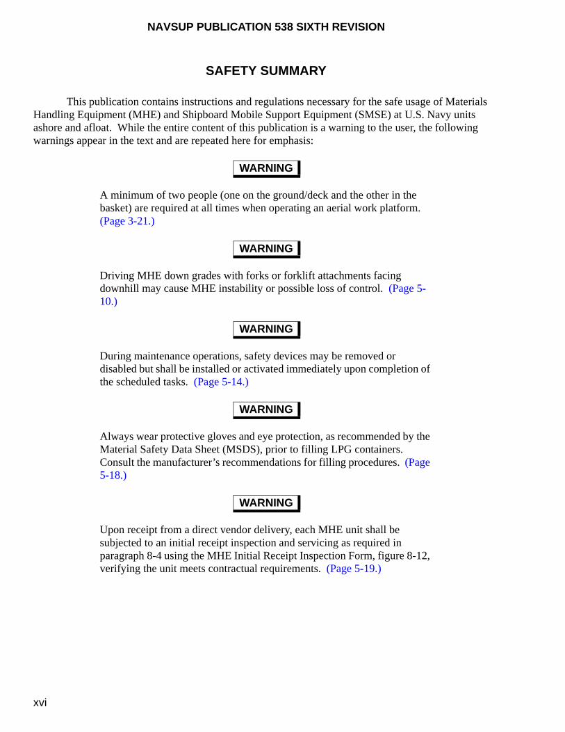
This publication contains instructions and regulations necessary for the safe usage of Materials Handling Equipment (MHE) and Shipboard Mobile Support Equipment (SMSE) at U.S. Navy units ashore and afloat. While the entire content of this publication is a warning to the user, the following warnings appear in the text and are repeated here for emphasis:
A minimum of two people (one on the ground/deck and the other in the basket) are required at all times when operating an aerial work platform. (Page 3-21.)
Driving MHE down grades with forks or forklift attachments facing downhill may cause MHE instability or possible loss of control. (Page 5-10.)
During maintenance operations, safety devices may be removed or disabled but shall be installed or activated immediately upon completion of the scheduled tasks. (Page 5-14.)
Always wear protective gloves and eye protection, as recommended by the Material Safety Data Sheet (MSDS), prior to filling LPG containers. Consult the manufacturer’s recommendations for filling procedures. (Page 5-18.)
Upon receipt from a direct vendor delivery, each MHE unit shall be subjected to an initial receipt inspection and servicing as required in paragraph 8-4 using the MHE Initial Receipt Inspection Form, figure 8-12, verifying the unit meets contractual requirements. (Page 5-19.)
WARNING
WARNING
WARNING
WARNING
WARNING

NAVSUP PUBLICATION 538 SIXTH REVISION
xvii
Type DS and DY MHE may be used in closed lighters afloat provided they meet federal, state and local regulations for air quality and noise pollution. Each activity must monitor the emissions in accordance with the manufacturer’s recommendations to ensure that the exhaust emissions do not exceed the personal exposure limits set forth by federal, state or local regulations. (Page 5-30.)
The use of powered MHE is forbidden in areas where dust vapors are known to, or can reasonably be expected to, reach explosive limits during routine operations (i.e., mixing, bulk weighing, screening, etc.). (Page 5-31.)
MHE powered by internal combustion engines may be used in partial operational areas ashore provided they meet federal, state and local regulations for air quality and noise pollution. Each activity must monitor the emissions in accordance with the manufacturer’s recommendations to ensure that the exhaust emissions do not exceed the personal exposure limits set forth by federal, state or local regulations. (Page 5-31.)
All shipboard forklift and electric pallet trucks, or ashore forklift and electric pallet trucks designated to handle ammunition and explosives are subjected to the operational or overload weight testing requirements documented in NAVSEA SW023-AH-WHM-010. The operational weight testing requirements prescribed in paragraphs 8-7.3 and 8-7.4 shall only apply to ashore units designated to handle general supply and HAZMAT (other than ammunition and explosives). (Page 8-25.)
When the mast is fully raised, ensure the operator’s hands are clear of the controls and the person marking and verifying the height is positioned to the side of the forklift truck. An observer must ensure that all personnel are clear of the mast prior to raising the rated load. (Page 8-26.)
WARNING
WARNING
WARNING
WARNING
WARNING
NAVSUP PUBLICATION 538 SIXTH REVISION
xviii
Do not touch spilled liquids without appropriate personal protective equipment. Spilled liquid is likely to be electrolyte which contains sulfuric acid. (Page 9-3.)
For units ashore, locally procured battery lifting beams may be used to lift MHE batteries provided they are maintained, inspected, tested and certified in accordance with NAVFAC P-307. (Page 9-5.)
For units afloat, the Mk 18 Mod 1 or Mod 2 Handling Beam, figure 9-3, is approved to lift batteries. The battery cover shall be kept closed to prevent the beam from accidentally coming into contact with the battery connecting terminals, causing a short circuit. (Page 9-5.)
Only use authorized battery lifting equipment to hoist lead-acid batteries and to connect to the battery lifting lugs. Do not use sling assemblies that would tend to squeeze or stretch the battery tray and lifting lugs as the load is applied. The Mk 18 Mod 1 or Mod 2 Handling Beam, figure 9-3, is approved for lifting batteries afloat, while locally procured lifting beams are approved ashore. (Page 9-8.)
Do not use the Mk 18 Mod 1 or Mod 2 Handling Beam with batteries without lift tabs or those that do not allow full contact with the lift hook throat. (Page 9-8.)
Severe burns can be caused by the sulfuric acid contained in batteries. In case of contact, thoroughly flush affected area with clean water. Obtain medical attention immediately. (Pages 9-10, 9-11, 9-28, and 9-30.)
An explosion can result from the hydrogen gas produced from battery charging. (Page 9-11.)
WARNING
WARNING
WARNING
WARNING
WARNING
WARNING
WARNING
NAVSUP PUBLICATION 538 SIXTH REVISION
xix
When mixing electrolyte, acid shall be poured into water, not water into acid. (Page 9-11.)
Verify the battery charger is in the OFF position before connecting or disconnecting batteries. (Page 9-19.)
Fluctuating dial readings, readings that are full scale, smoke or violent gassing may indicate a shorted battery cell or incorrect connection. Turn the charger immediately to the OFF position and recheck the connections and settings. (Page 9-19.)
Do not attempt to charge a battery with loose, damaged or corroded terminals. (Page 9-24.)
Do not add acid to an aging cell in an attempt to increase its capacity. Decreased service life will result. (Page 9-29.)
Never use electrolyte with a specific gravity higher than 1.400. (Page 9-30.)
Refer to the Material Safety Data Sheet (MSDS) for Grease, Aircraft and Instruments, MIL-PRF-23827. The precautions, procedures and special protection information concerning the grease shall be followed. (Pages 10-2, 10-5, 11-10)
Refer to the Material Safety Data Sheets (MSDS) for Multi-Purpose Lubrication/Corrosion Inhibitor CRC 3-36. The precautions, procedures and special protection information concerning the lubricant shall be followed. (Page 11-2)
WARNING
WARNING
WARNING
WARNING
WARNING
WARNING
WARNING
WARNING

NAVSUP PUBLICATION 538 SIXTH REVISION
xx
Refer to the Material Safety Data Sheet (MSDS) for Compound, Silicone, Soft Film, DC-6 or G-24. The precautions, procedures and special protection information concerning the compound shall be followed. (Pages 10-3, 11-10.)
Refer to the Material Safety Data Sheet (MSDS) for CRC Industrial Duty Silicone. The precautions, procedures, and special protection information concerning the silicone shall be followed. (Pages 10-3, 11-8.)
Refer to the Material Safety Data Sheet (MSDS) for Lubricating Oil, Engine, MIL-L-21260, Grade 30. The precautions, procedures and special protection information concerning the oil shall be followed. (Pages 10-3, 11-6.)
Refer to the Material Safety Data Sheet (MSDS) for Fuel Soluble Lubricity Improver Corrosion Inhibitor, MIL-I-25017. The precautions, procedures and special protection information concerning the corrosion inhibitor shall be followed. (Page 10-4.)
Refer to the Material Safety Data Sheet (MSDS) for CRC 3-36Ò, or LPS 814, or ALOX 22028CM-3. The precautions, procedures and special protection information concerning the lubricant shall be followed. (Page 10-5.)
Refer to the Material Safety Data Sheet (MSDS) for Alcohol, Denatured Ethyl, O-E-760. The precautions, procedures and special protection information concerning the cleaning solvent shall be followed. (Pages 10-9, 11-13.)
WARNING
WARNING
WARNING
WARNING
WARNING
WARNING
NAVSUP PUBLICATION 538 SIXTH REVISION
xxi
Refer to the Material Safety Data Sheet (MSDS) for Cleaning Compound, P-C-437. The precautions, procedures and special protection information concerning the compound shall be followed. (Page 11-2.)
Refer to the Material Safety Data Sheet (MSDS) for Antifreeze, A-A-52624. The precautions, procedures and special protection information concerning the antifreeze shall be followed. (Page 11-2.)
Refer to the Material Safety Data Sheet (MSDS) for Lubricating Oil, Combat/Tactical 15W-40 in accordance with MIL-PRF-2104, or Lubricating Oil, Gear, Multi-Purpose in accordance with SAE J2360 (supersedes MIL-PRF-2105). The precautions, procedures and special protection information concerning these oils shall be followed. (Page 11-3.)
Refer to the Material Safety Data Sheet (MSDS) for Preservative, Oil, Light Viscosity, MIL-P-46002, Type 1. The precautions, procedures and special protection concerning the oil shall be followed. (Page 11-5.)
Refer to the Material Safety Data Sheet (MSDS) for Preservative, Oil, Light Viscosity, MIL-P-46002, Type 1. The precautions, procedures and special protection concerning the oil shall be followed. (Page 11-5.)
The hot water from the wand nozzle should never be recycled back into the hot water tank in an attempt to increase the water temperature at the wand nozzle. (Page G-6.)
The hot water from the wand nozzle should never be recycled back into the hot water tank in an attempt to increase the water temperature at the wand nozzle. (Page G-7.)
WARNING
WARNING
WARNING
WARNING
WARNING
WARNING
WARNING
NAVSUP PUBLICATION 538 SIXTH REVISION
xxii
The following caution statements appear in the text of this manual, and are repeated here for emphasis:
The use of salt water to clean MHE/SMSE is strictly prohibited. (Page 5-2.)
Side loading the mobile cargo crane may cause structural damage to the boom, causing it to collapse. (Page 5-8.)
Mast and fork restraint devices must be removed prior to operating components to prevent damage to the MHE. (Page 8-15.)
In sub-freezing temperatures, water should be added one hour before charging is completed or at beginning of equalizing charge to ensure proper mixing with the electrolyte. (Page 9-3.)
Ensure that only a vertical force is applied to the battery lifting lugs/eyes during the battery lifting test. This is accomplished using several approval battery lifting beams. Do not attach sling assemblies that would tend to squeeze or stretch the battery tray and lifting lugs/eyes when the load is applied. (Page 9-5.)
When cleaning battery connections, verify the lead coating is not removed from terminals, exposing copper. (Page 9-9.)
Lead-acid batteries shall only be charged by trained and authorized personnel. (Page 9-11.)
CAUTION
CAUTION
CAUTION
CAUTION
CAUTION
CAUTION
CAUTION

NAVSUP PUBLICATION 538 SIXTH REVISION
xxiii
To avoid damaging the battery, never allow the electrolyte temperature to exceed 115 °F during charging. Reduce or stop current if electrolyte reaches this temperature. (Page 9-12.)
Do not continuously exceed a battery beyond 80 percent discharge. Its service life will be greatly diminished. (Page 9-12.)
Automatic battery filler has an adjustable nozzle that allows a precise shut off capability for watering batteries and must be properly adjusted when received to avoid overfilling. (Page 9-13.)
Do not use these procedures for gel or absorbed glass mat type batteries. (Page 9-14.)
Do not disconnect the battery by pulling on the cable. (Page 9-15.)
Do not use the plastic coolant tester tube when sampling battery electrolyte, which may damage the instrument. (Page 9-18.)
Do not overfill cells with distilled water because levels will rise during charging spilling the electrolyte. For battery cells with low levels, use the battery filler syringe only and not the automatic (2 quart) battery filler for filling to prevent overfilling prior to charging. (Page 9-18.)
CAUTION
CAUTION
CAUTION
CAUTION
CAUTION
CAUTION
CAUTION
NAVSUP PUBLICATION 538 SIXTH REVISION
xxiv
Operational requirements may dictate temperatures exceeding 90 °F during charging. Do not allow battery temperatures to exceed 115 °F during charging, which will reduce its service life. Allow as much “cooling off” time as operationally possible before and after battery charging. (Page 9-19.)
Ensure the battery vent/fill caps are in place before using acid neutralizing solution to prevent damage to the cells. (Page 9-22.)
Do not overfill battery cells with distilled water because the levels will rise during charging spilling the electrolyte. (Page 9-24.)
Do not place a battery on a charger when the cell temperature is 90 °F or greater. Allow the battery to cool. (Page 9-24.)
Do not short meter probes across the battery connector terminals to prevent damage to the meter. Page 9-27.)
Use only distilled or de-mineralized water for filling lead-acid batteries.(Page 9-28.)
Do not add distilled or de-mineralized water until visual inspection shows that top of separators/plates are visible. (Page 9-28.)
Prior to battery charging if electrolyte is not visible above the battery plates add distilled water to a level just above the battery plates. (Page 9-28.)
CAUTION
CAUTION
CAUTION
CAUTION
CAUTION
CAUTION
CAUTION
CAUTION

NAVSUP PUBLICATION 538 SIXTH REVISION
xxv
Do not overfill battery cells. Overfilling will likely cause electrolyte spillage, which will eventually lead to tray corrosion, ground paths, and loss of battery capacity. (Page 9-28.)
Sulfuric acid should never be added to a cell without first ensuring that charging will not restore specific gravity to normal values. (Page 9-29.)
Never make a specific gravity adjustment on a cell which does not gas freely on charge. (Page 9-29.)
Ensure all cells are gassing prior to starting any gravity adjustment.(Page 9-30.)
Only clean a battery with an approved neutralizer/cleaner or a mixture of bicarbonate of soda and water (one pound of bicarbonate to one gallon of water). Ensure cleaning mixture does not get into battery cells. (Page 9-31.)
Prior to cleaning a battery, ensure all vent plugs are in place. (Page 9-31.)
All batteries should be stored or stowed under cover and in a diked or contained area to prevent any electrolyte from accidentally entering the environment. (Page 9-32.)
CAUTION
CAUTION
CAUTION
CAUTION
CAUTION
CAUTION
CAUTION
NAVSUP PUBLICATION 538 SIXTH REVISION
xxvi
Batteries and acids should be stored or stowed away from sewer and storm drains and from sources of heat. (Page 9-32.)
Leaking or cracked batteries and cells must be provided with adequate containment during storage and transportation. (Page 9-32.)
Precautions must be taken to assure hydrostatic lock-up does not occur causing severe engine damage. Spark plugs, fuel injectors, glow plugs, etc., must remain out during this procedure or engine damage may result. (Page 11-7.)
Mask friction-type brake linings from overspray. Damage to lining material will result. (Page 11-8.)
CAUTION
CAUTION
CAUTION
CAUTION

NAVSUP PUBLICATION 538 SIXTH REVISION
1-1
CHAPTER 1
INTRODUCTION
1-1. PURPOSE
This publication provides administrative regulations, technical instructions, personnel training requirements, safety precautions, operational and preventive maintenance requirements, extended storage procedures, and battery maintenance and charging procedures commonly available for U.S. Navy Materials Handling Equipment (MHE) and, as appropriate, Shipboard Mobile Support Equipment (SMSE). Also, this publication identifies and describes the approved types of MHE (and their associated forklift truck attachments) and SMSE. These documented requirements, in conjunction with locally developed instructions, are intended to provide for the safe use of MHE and to extend its in-service life cycle.
1-2. SCOPE
This publication is applicable to all Navy activities ashore and afloat which have United States Navy (USN) Registration Numbers assigned to MHE and SMSE without regard to employer. Refer to paragraph 4-3.4a for regulations involving contractor and non-Government personnel employed under a Navy command. The provisions of this publication apply to Navy-owned MHE and SMSE assigned to shore activities, land-based operating forces, forces afloat, and Fleet Issue Control Points (FICP’s). This publication is not applicable to tactical MHE assigned to deployable Fleet Marine Forces and Marine Corps activities for which the Commandant of the Marine Corps (CMC) has the primary support responsibility under the provisions of MCO P11262.2 (series). For MHE assigned to handle ammunition and explosives, the regulations prescribed in NAVSEA SW023-AH-WHM-010 shall apply. Other government MHE programs may use this publication as a guide.
1-3. CANCELLATION
This publication supersedes and cancels NAVSUP Publication 538, Fifth Revision, dated 1 July 2010.
1-4. ORGANIZATION OF PUBLICATION
This publication is divided into 13 chapters. Chapter 2 documents the administrative responsibilities from the Program Management down to the user levels of MHE. Chapter 3 identifies and describes the approved types of MHE and associated forklift truck attachments commonly used by the Navy. Chapter 4 lists the processes to select training, license personnel as powered MHE operators, and authorize personnel as local instructors for the purpose of issuing a license for powered MHE operators. Chapter 5 provides the safety precautions associated with operating and maintaining MHE, the approved operational areas, and operator and instructor qualifications. Chapter 6 describes the Equipment

NAVSUP PUBLICATION 538 SIXTH REVISION
1-2
Management and Control System (EMACS) preventive maintenance program for recording and maintaining services performed on MHE and indicating specific areas that require servicing. Chapter 7 details the procedures for reporting deficiencies on new or existing MHE. Chapter 8 addresses the basic preventive maintenance practices that will assure the satisfactory performance of MHE. Chapter 9 provides recommended guidelines for the maintenance and charging procedures of lead-acid batteries used in all electric-powered MHE. Chapter 10 describes short term procedures, commonly called “live storage,” for an anticipated MHE storage duration of less than 24 months (2 years). Chapter 11 describes long term procedures, commonly called “dead storage,” for MHE storage of greater than 24 months (2 years). Finally, chapter 12 is solely dedicated for the life cycle management of SMSE by identifying and describing the approved types of SMSE, documenting training, qualification and operator licensing requirements, prescribing related safety precautions, and detailing the basic preventive maintenance practices and periodic requirements.
1-5. REPAIR TIME STANDARDS SUPPLEMENT
The known Navy repair time standards, by section according to the equipment cost code, and actual industrial MHE manufacturers repair time standards (previously chapter 10 and appendix E, respectively, documented in the Fourth Revision of this publication) have been moved as a supplement to this publication. These repair time standards now appear as an individual file on this DVD entitled, "Repair Time Standards Supplement".
1-6. REFERENCE DOCUMENTS
Appendix A lists all the documents containing technical or administrative information applicable to and referenced in this publication. These documents are essential for complete understanding of administrative, operating, maintaining and handling MHE or SMSE. Applicable documents shall be maintained as a collection of current information pertaining to all aspects of MHE or SMSE operations and maintenance.
1-7. MHE OPERATOR TRAINING COURSE
Appendix B provides the training course established as the minimum requirements that Naval personnel must successfully meet prior to being issued a powered industrial MHE license to handle general supplies or hazardous materials (other than ammunition and explosives).
1-8. MATERIALS HANDLING EQUIPMENT (MHE) ASSIST CHECKLIST
Appendix C provides a checklist for afloat and ashore use, as appropriate, to assist the MHE representative and the ship/activity evaluate their MHE operations and to provide needed assistance and information.
1-9. SHIPMENT AND TRANSPORTATION OF MHE
Appendix D provides general shipment and transportation guidelines for MHE intended to be transported on flatbed trailers, or enclosed vans and trailers for short term storage, long term storage, or

NAVSUP PUBLICATION 538 SIXTH REVISION
1-3
general truckload requirements. These procedures are presented to ensure that MHE will not be degraded or damaged during shipment.
1-10. EMERGENCY RECLAMATION PROCEDURES
Appendix E provides emergency reclamation procedures that are required to prevent damage and corrosion to MHE/SMSE when exposed to salt spray, water immersion, or fire extinguishing agents. It is essential to immediately begin reclamation procedures of cleaning, drying, preservation, repair and operational functions.
1-11. DECK SCRUBBER OPERATOR’S TRAINING COURSE
Appendix F provides the training course meeting the minimum requirements that U.S. Navy shipboard personnel must successfully meet prior to operating the deck scrubber (Model No. SRS1550-DN-A).
1-12. QRE-3001A POWER/PRESSURE WASHER OPERATOR’S TRAINING COURSE
Appendix G establishes the policy, responsibilities and requirements for training and licensing personnel to operate a QRE-3001A Power/Pressure Washer.
1-13. TERMS AND DEFINITIONS
The following are terms and definitions that are contained throughout this publication. The reader is encouraged to review and understand these terms and definitions to ensure that they are understood.
1-13.1. A-4 CONDITION. The condition of previously used material that is repaired, reconditioned, overhauled and remanufactured to function and look like new, and issue to all customers without limitations or restrictions. MHE that have major overhaul performed on all systems with corrosion control performed on all assemblies circuits and systems. An A-4 unit will be capable of performing its original intended service life.
1-13.2. ACCUMULATED REPAIR EXPENDITURE LIMITS. Are applicable to the sum of all scheduled inspection and repair costs incurred during the entire life of the item. This includes the price of parts actually consumed in the repair operation, the exchange charge for complete assemblies or subassemblies installed, and direct and indirect (shop charges only) labor involved.
1-13.3. COMMANDING OFFICER/OFFICER-IN-CHARGE (CO/OIC). For the purpose of this publication, the CO/OIC is defined as the title of the senior officer or responsible authority (e.g., resident director, senior contracting official) at activities ashore or the senior officer aboard ship who has the full responsibility for the operation and maintenance of the ship.
1-13.4. EQUIPMENT MANAGEMENT AND CONTROL SYSTEM (EMACS). An automated, server-based application system that allows Navy users of MHE maintain asset visibility and economically manage maintenance.

NAVSUP PUBLICATION 538 SIXTH REVISION
1-4
1-13.5. MATERIALS HANDLING EQUIPMENT (MHE). All self-propelled equipment normally used in storage and handling operations in and around warehouses, shipyards, industrial plants, airfields, magazines, depots, docks, terminals, and aboard ships. It includes all self-propelled MHE, such as, but not limited to, warehouse tractors, forklift trucks, platform trucks, pallet trucks, straddle carrying trucks, 463L aircraft loaders, and automated materials handling systems. It also includes non-powered shipboard pallet trucks.
1-13.6. ONE-TIME REPAIR. Expenditure limits for MHE are applicable to each complete repair job performed on a unit, with the exception for Service Life Extension Program (SLEP) costs.
1-13.7. PREVENTIVE MAINTENANCE. Scheduled maintenance that is the responsibility of and performed by a using organization on its assigned equipment. It consists of the inspection, service, surveillance, adjusting, and lubrication of equipment in order to minimize breakdown and keep the equipment in optimum operating condition.
1-13.8. REPAIR. As used in this publication, denotes the procedure or method used to return MHE to operational condition after failure.
1-13.9. SERVICE LIFE EXTENSION PROGRAM (SLEP). Managed by Commander, NAVSUP Weapon Systems Support (NAVSUP WSS) [formerly Naval Inventory Control Point (NAVICP)], the Navy’s major, scheduled overhaul/remanufacture program that effectively extends the life of MHE and returns it back to its original service life (in like-new A-4 condition).
1-14. REPORTING CONFLICTS, ERRORS AND OMISSIONS IN PUBLICATION
All users are requested to arrange for the maximum practical use and evaluation of this publication and to the referenced technical manuals. If a conflict exists between this publication and OPNAV or higher echelon instructions, those instructions shall take precedence. If a conflict exists between this publication and any other technical instructions and procedures, the provisions specified in this publication shall take precedence. All conflicts noted shall be reported to the Program Manager at Commander, NAVSUP Weapon Systems Support (NAVSUP WSS) [formerly Naval Inventory Control Point (NAVICP)], 5450 Carlisle Pike, Code 8341, P.O. Box 2020, Mechanicsburg, PA 17055-0788 on NAVSUP Technical Manual Deficiency/Evaluation Report (TMDER). To facilitate such reporting, a copy of this TMDER is included at the end of this publication and may be used for completion and submission. All feedback comments will be thoroughly investigated and those who provided the comments will be advised of the outcome. Valid outcomes will be incorporated into the next revision or change to this publication.
1-15. OBTAINING COPIES OF THIS PUBLICATION
1-15.1. HARD COPIES. Hard copies of this publication should be ordered via print on demand requisition (MILSTRIP) using the National Stock Number (NSN) assigned to this publication. Requisitions should be forwarded to Document Automation and Production Service (DAPS), 5450 Carlisle Pike, Building 410, P.O. Box 2020, Mechanicsburg, PA 17055-0788, phone number 1-215-697-6257, or by accessing them at www.daps.dla.mil or using the Naval Logistics Library (NLL) website at www.nll.navsup.navy.mil (password required). Activities may reproduce additional hard copies of this publication for their own use.

NAVSUP PUBLICATION 538 SIXTH REVISION
1-5/(1-6 Blank)
1-15.2. DVD COPIES. DVD copies of this publication, which is located on the Explosives Safety Technical Manual (ESTM) DVD, published by Naval Ordnance Safety and Security Activity (NOSSA), should be forwarded to Director, Naval Surface Warfare Center (NAVSURFWARCEN), Indian Head Division Detachment Picatinny, Naval Packaging, Handling, Storage, and Transportation (PHST) Center, Code G1, Building 458, Whittemore Avenue, Picatinny Arsenal, NJ 07806-5000. Activities may replicate additional DVD’s of this publication for their own use.
1-16. DISTRIBUTION OF PUBLICATION
Correspondence involving distribution quantities, address changes, etc., should be forwarded to Commander, NAVSUP Weapon Systems Support (NAVSUP WSS) [formerly Naval Inventory Control Point (NAVICP)], 5450 Carlisle Pike, Code 8341, P.O. Box 2020, Mechanicsburg, PA 17055-0788.
1-17. DATE OF PUBLICATION
The date of this publication, as shown on the title page, is the estimated date of distribution. However, the publication, revision, or change is effective upon receipt, regardless of the date shown on the title page.

This page left intentionally blank

NAVSUP PUBLICATION 538 SIXTH REVISION
2-1
CHAPTER 2
ADMINISTRATION
2-1. AUTHORITY
By the authority of the Secretary of the Navy (SECNAV) and the Chief of Naval Operations (CNO) instructions, SECNAVINST 4440.31 (series) and OPNAVINST 4460.1A, the Naval Supply Systems Command (NAVSUPSYSCOM) has been assigned the overall responsibility for the administration and control of all U.S. Navy Materials Handling Equipment (MHE) and Shipboard Mobile Support Equipment (SMSE). As assigned by NAVSUP Weapon Systems Support (NAVSUP WSS) [formerly Naval Inventory Control Point Mechanicsburg (NAVICP-M)] serves as the overall program manager, life cycle manager, and Acquisition Engineering Agency (AEA) for Navy MHE/SMSE.
2-2. PROGRAM RESPONSIBILITIES
The following are the MHE Program responsibilities as delineated in NAVSUPINST 10490.33 (series) and NAVICPINST 10490.4 (series). The next revision to these instructions will also contain program responsibilities for SMSE, but are documented here in advance.
2-2.1. PROGRAM MANAGER. The MHE/SMSE program manager, NAVSUP WSS (Code 8341), will:
a. Establish Navy-wide procurement, maintenance, and management policies to support programs and allowances authorized by CNO.
b. Review and incorporate strategic philosophy into program management, provide formal budget preparation guidance and defend the budget.
c. Review Program Objectives Memorandum (POM) inputs for the new requirements and refer them to the appropriate CNO program sponsor for funding support.
d. Establish policy for the allocation, administration, and use of all assigned equipment, in accordance with the military requirements established by CNO and operational requirements of other commands and offices.
e. Monitor the implementation of standards for operation and general use of Navy MHE/SMSE.
f. Administer public laws and regulations relating to the acquisition, use and disposal of MHE/SMSE.
g. Review and approve life expectancy and repair limit criteria for MHE/SMSE.
NAVSUP PUBLICATION 538 SIXTH REVISION
2-2
h. Oversee the review of MHE/SMSE specifications in connection with the Department of Defense (DOD) Standardization Program. Approve all new MHE/SMSE specifications and significant revisions to existing MHE/SMSE specifications for the Navy.
i. Approve standards for training of MHE/SMSE operating and maintenance personnel.
j. Through command channels and in coordination with other commands or offices, establish technical and operational standards to comply with appropriate safety regulations.
k. Coordinate requirements for cost accounting and cost reporting procedures with the Comptroller of the Navy and other interested commands and offices.
l. Develop and maintain the policy for MHE/SMSE Integrated Logistic Support Plans (ILSP).
m. Provide the necessary information on approved installation/modification of Automated Materials Handling Systems (AMHS) or warehouse improvement projects which affect MHE requirements.
n. Review and approve MHE/SMSE initial allowances and subsequent allowance change requests (ACR’s) wherein agreement cannot be reached with the requesting activity, or when significant budgetary impacts may be realized.
o. Provide MHE/SMSE management capabilities to all Navy users and managers via the Navy’s Equipment and Management Control Systems (EMACS), with the specific responsibilities documented in paragraph 6-5.1.
p. Submit budget requirements and establish program management guidelines for the MHE Service Life Extension Program (SLEP). For SMSE, plan for the scheduled 18- and 36-month servicing.
q. Oversee the AEA function and fund, task and monitor the MHE/SMSE In-Service Engineering Agency (ISEA) function.
r. Oversee the management and control of MHE stored as War Reserve Materiel (WRM).
s. Oversee the implementation and management of NAVSUP Fleet Logistics Center (NAVSUP FLC) [formerly Fleet and Industrial Supply Center (FISC)] tasking for MHE.
t. Coordinate with the Type Commander (TYCOM) MHE Manager who is familiar with Fleet MHE/SMSE matters.
2-2.2. LIFE CYCLE MANAGER. The MHE/SMSE life cycle manager, NAVSUP WSS (Code 8341), will:
a. Serve as AEA for the Navy’s MHE/SMSE program.

NAVSUP PUBLICATION 538 SIXTH REVISION
2-3
b. Perform all inventory control functions for MHE/SMSE assigned to Navy activities, afloat and ashore, to include Fleet Inventory Control Points (FICP’s) and WRM.
c. Through command channels, and in coordination with the appropriate Naval Air (NAVAIR), Naval Sea (NAVSEA), Naval Facility (NAVFAC) Systems Command, TYCOM, or TYCOM MHE Manager with respect to MHE/SMSE assigned to ships, assist in determining Navy-wide MHE/SMSE requirements in support of existing programs, previously established allowances, approved allowance changes, new allowances and new programs.
d. Support the Navy’s EMACS program, with the specific responsibilities documented in paragraph 6-5.1.
e. Determine, promulgate and monitor standards for activity use in determining requirements for selection, application, operations and use of MHE/SMSE.
f. Develop and defend MHE/SMSE budgets using inventory, new requirements, replacement and procurement data for submittal as required.
g. Coordinate POM inputs for new requirements and provide as required.
h. Coordinate and consolidate requirements, verify and approve user technical requirements, initiate procurement, and coordinate and monitor consignment and delivery of MHE/SMSE for the following programs:
(1) Navy replacement program.
(2) Navy Working Capital Fund (NWCF) activities, to include NAVSUP NWCF, and Ships Construction Navy (SCN) programs.
(3) New programs, new allowances, military construction and facility upgrades.
i. Prioritize the delivery of replacement and new MHE/SMSE based on operational requirements and performance of the activity in meeting utilization goals.
j. Oversee management of WRM MHE stock in accordance with NAVSUP WRM and CNO-approved requirements and guidelines.
k. Monitor utilization of MHE assigned to shore activities and land-based operating forces.
l. Assign Navy Registration Numbers to all Navy MHE.
m. Establish criteria for the replacement, induction into the SLEP, or retirement of MHE using SLEP and DOD guidance.
n. Develop and administer technical and operational standards in compliance with appropriate safety regulations.
NAVSUP PUBLICATION 538 SIXTH REVISION
2-4
o. Manage the exchange, reassignment, and disposal of MHE/SMSE for the Navy in accordance with current regulations.
p. Provide recommended revisions to MHE/SMSE cost accounting and cost reporting procedures for coordination with the Comptroller of the Navy (NAVCOMPT).
q. As required, review submissions by activities of other commands (including Navy ships) for procurement of powered MHE, non-powered shipboard pallet trucks, SMSE and MHE industrial storage batteries for conformance with military standards and specifications.
r. Provide acquisition engineering data to the Defense Logistics Agency (DLA) for Federal Supply Classes 3920 (shipboard manual pallet trucks only), 3930 (powered MHE), SMSE and 6140 (MHE batteries only) applicable to Navy programs.
s. Chair provisioning conferences and effect provisioning for Navy MHE/SMSE by developing and maintaining Allowance Parts Lists (APL’s) and Lead APL’s.
t. Develop, maintain, coordinate and manage military and federal specifications and standards for powered and non-powered MHE/SMSE and submit new specifications and significant revisions to existing specifications for approval. Effect standardization of equipment practical in compliance with procedures established by the DOD Standardization Program. Coordinate specification reviews with the ISEA as required.
u. Establish and chair a Configuration Control Board (CCB), and retain responsibility for MHE configuration management.
v. Evaluate manufacturer and repair facilities based on past performance and capabilities to determine “best value” manufacturers.
w. Develop, approve and maintain MHE/SMSE technical manual (TM) specifications and standards. Review, evaluate and approve contractor maintenance manuals and technical publications.
x. Function as the preparing activity and Navy custodian for military and industry specifications and standards applicable to powered and non-powered MHE/SMSE and industrial storage batteries for electric powered MHE.
2-2.3. IN-SERVICE ENGINEERING AGENT (ISEA). The Naval Surface Warfare Center (NAVSURFWARCEN) Indian Head Division Detachment Picatinny, Naval Packaging, Handling, Storage and Transportation (PHST) Center, has been designated by NAVSUP and NAVSUP WSS to serve as the MHE/SMSE ISEA. The ISEA will:
a. Maintain the MHE/SMSE ILSP and other maintenance plans, procedures and standards to ensure MHE/SMSE is managed and repaired at the most economical level. Review Lead APL’s.
b. Assist the AEA in reviewing and approving TM’s, maintenance manuals, and technical publications for contractual compliance and equipment applicability.
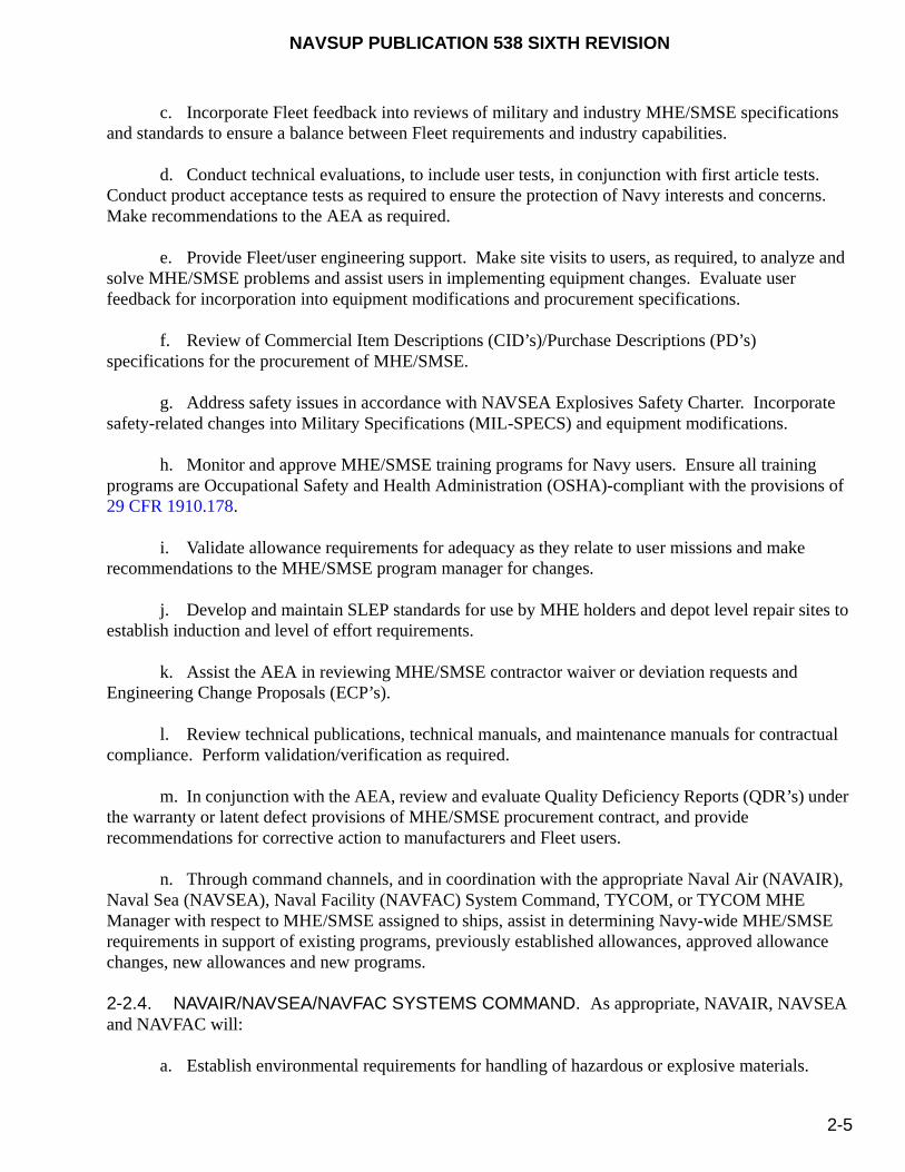
NAVSUP PUBLICATION 538 SIXTH REVISION
2-5
c. Incorporate Fleet feedback into reviews of military and industry MHE/SMSE specifications and standards to ensure a balance between Fleet requirements and industry capabilities.
d. Conduct technical evaluations, to include user tests, in conjunction with first article tests. Conduct product acceptance tests as required to ensure the protection of Navy interests and concerns. Make recommendations to the AEA as required.
e. Provide Fleet/user engineering support. Make site visits to users, as required, to analyze and solve MHE/SMSE problems and assist users in implementing equipment changes. Evaluate user feedback for incorporation into equipment modifications and procurement specifications.
f. Review of Commercial Item Descriptions (CID’s)/Purchase Descriptions (PD’s) specifications for the procurement of MHE/SMSE.
g. Address safety issues in accordance with NAVSEA Explosives Safety Charter. Incorporate safety-related changes into Military Specifications (MIL-SPECS) and equipment modifications.
h. Monitor and approve MHE/SMSE training programs for Navy users. Ensure all training programs are Occupational Safety and Health Administration (OSHA)-compliant with the provisions of 29 CFR 1910.178.
i. Validate allowance requirements for adequacy as they relate to user missions and make recommendations to the MHE/SMSE program manager for changes.
j. Develop and maintain SLEP standards for use by MHE holders and depot level repair sites to establish induction and level of effort requirements.
k. Assist the AEA in reviewing MHE/SMSE contractor waiver or deviation requests and Engineering Change Proposals (ECP’s).
l. Review technical publications, technical manuals, and maintenance manuals for contractual compliance. Perform validation/verification as required.
m. In conjunction with the AEA, review and evaluate Quality Deficiency Reports (QDR’s) under the warranty or latent defect provisions of MHE/SMSE procurement contract, and provide recommendations for corrective action to manufacturers and Fleet users.
n. Through command channels, and in coordination with the appropriate Naval Air (NAVAIR), Naval Sea (NAVSEA), Naval Facility (NAVFAC) System Command, TYCOM, or TYCOM MHE Manager with respect to MHE/SMSE assigned to ships, assist in determining Navy-wide MHE/SMSE requirements in support of existing programs, previously established allowances, approved allowance changes, new allowances and new programs.
2-2.4. NAVAIR/NAVSEA/NAVFAC SYSTEMS COMMAND. As appropriate, NAVAIR, NAVSEA and NAVFAC will:
a. Establish environmental requirements for handling of hazardous or explosive materials.
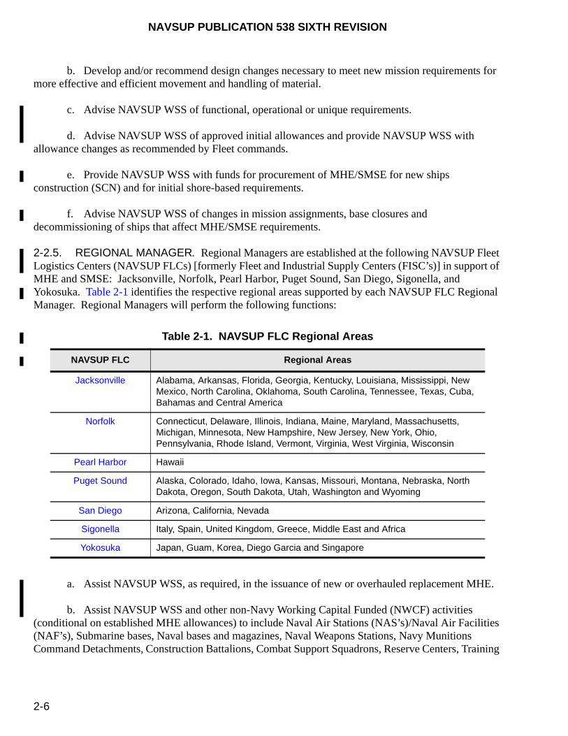
NAVSUP PUBLICATION 538 SIXTH REVISION
2-6
b. Develop and/or recommend design changes necessary to meet new mission requirements for more effective and efficient movement and handling of material.
c. Advise NAVSUP WSS of functional, operational or unique requirements.
d. Advise NAVSUP WSS of approved initial allowances and provide NAVSUP WSS with allowance changes as recommended by Fleet commands.
e. Provide NAVSUP WSS with funds for procurement of MHE/SMSE for new ships construction (SCN) and for initial shore-based requirements.
f. Advise NAVSUP WSS of changes in mission assignments, base closures and decommissioning of ships that affect MHE/SMSE requirements.
2-2.5. REGIONAL MANAGER. Regional Managers are established at the following NAVSUP Fleet Logistics Centers (NAVSUP FLCs) [formerly Fleet and Industrial Supply Centers (FISC’s)] in support of MHE and SMSE: Jacksonville, Norfolk, Pearl Harbor, Puget Sound, San Diego, Sigonella, and Yokosuka. Table 2-1 identifies the respective regional areas supported by each NAVSUP FLC Regional Manager. Regional Managers will perform the following functions:
a. Assist NAVSUP WSS, as required, in the issuance of new or overhauled replacement MHE.
b. Assist NAVSUP WSS and other non-Navy Working Capital Funded (NWCF) activities (conditional on established MHE allowances) to include Naval Air Stations (NAS’s)/Naval Air Facilities (NAF’s), Submarine bases, Naval bases and magazines, Naval Weapons Stations, Navy Munitions Command Detachments, Construction Battalions, Combat Support Squadrons, Reserve Centers, Training
Table 2-1. NAVSUP FLC Regional Areas
NAVSUP FLC Regional Areas
Jacksonville Alabama, Arkansas, Florida, Georgia, Kentucky, Louisiana, Mississippi, New Mexico, North Carolina, Oklahoma, South Carolina, Tennessee, Texas, Cuba, Bahamas and Central America
Norfolk Connecticut, Delaware, Illinois, Indiana, Maine, Maryland, Massachusetts, Michigan, Minnesota, New Hampshire, New Jersey, New York, Ohio, Pennsylvania, Rhode Island, Vermont, Virginia, West Virginia, Wisconsin
Pearl Harbor Hawaii
Puget Sound Alaska, Colorado, Idaho, Iowa, Kansas, Missouri, Montana, Nebraska, North Dakota, Oregon, South Dakota, Utah, Washington and Wyoming
San Diego Arizona, California, Nevada
Sigonella Italy, Spain, United Kingdom, Greece, Middle East and Africa
Yokosuka Japan, Guam, Korea, Diego Garcia and Singapore
NAVSUP PUBLICATION 538 SIXTH REVISION
2-7
Schools and Battalions, Expeditionary bases, Test Facilities, and Naval Medical Centers in identifying requirements and requesting replacement MHE.
c. Assist in identifying potential sources for maintenance and repair and/or leasing services as required or requested.
d. Manage regional inventory databases, via EMACS, in order to provide required updates to the Navy central database at NAVSUP WSS. Specific EMACS responsibilities are documented in paragraph 6-5.2.
e. Provide summaries of cumulative MHE maintenance costs required in EMACS when requested by equipment allowance holders.
f. Maintain MHE/SMSE pool inventories to service shipboard requirements and maintain limited MHE pool inventories to service shore-based regional MHE requirements. Manage both a shipboard FICP (except NAVSUP FLC Jacksonville and NAVSUP FLC Sigonella) and a shore-based pool of MHE supporting OPN activity assets and NAVSUP FLC assets, as applicable, with allowances established by NAVSUP WSS. Both shipboard and shore-based pool assets, and related funding will be maintained separately from normal NAVSUP FLC assets.
g. With NAVSUP WSS, manage the regional SLEP process, to include site visits, determination of induction candidates, funds management, new procurements, acceptance inspections, and management of in-house mini-SLEP service providers where applicable.
h. Make available or identify a source for either shipboard MHE maintenance training or a self-help maintenance and repair program to support Fleet training and maintenance requirements, and MHE operator training as applicable.
i. Coordinate with NAVSUP WSS for prior approval for Navy OPN activities to procure, condemn as excess, swap, exchange, or obtain by other means MHE/SMSE.
j. For base closures, if requested, the NAVSUP FLC Regional Manager will evaluate all MHE assets to be made available and provide recommendations to NAVSUP WSS as outlined in paragraph 2-11. Once final disposition of the MHE is received from NAVSUP WSS, the NAVSUP FLC Regional Manager will update the EMACS records as required. MHE excess and disposal procedures shall follow the requirements outlined in paragraph 2-11.
k. Assist NAVSUP WSS in evaluating the annual data call for projected requirements and recommend the most economical means of satisfying the activity’s requirements through the SLEP process, shore-based pool, excess MHE or new procurement.
l. When applicable, maintain and monitor the condition of WRM MHE pool assets. Coordinate all movements and/or equipment re-designations with NAVSUP WSS. For any NAVSUP FLC-assigned WRM, the NAVSUP FLC Regional Manager will be responsible for the following:
(1) Receipt, storage, periodic maintenance and repairs of WRM MHE.
NAVSUP PUBLICATION 538 SIXTH REVISION
2-8
(2) Prepare annual budget requests for the NAVSUP WRM MHE sponsor in accordance with established guidelines to maintain the WRM in A-4 condition or better.
(3) Forward any request for loan or issue of WRM MHE to NAVSUP WSS for resolution/authorization.
(4) Upon notification from NAVSUP WSS Program Manager or by direction of CNO, issue, loan, or transfer WRM MHE.
NOTE
Refer to NAVSUP Publication 717 for other specific requirements related to WRM.
2-2.6. MAJOR CLAIMANT. The major claimant will:
a. Advise NAVSUP WSS and the respective NAVSUP FLC Regional Manager of any changes in mission or other functional, operational or unique conditions that may affect MHE requirements for the respective activities.
b. Recommend approval or disapproval of an activity’s Allowance Change Request (ACR), as described in paragraphs 2-3.2 and 2-3.3, prior to forwarding to NAVSUP WSS.
c. Budget and fund new mission or initial allowance requirements. As applicable, fund the user activities for maintenance and repairs of MHE.
d. Ensure respective activities are aware of the MHE SLEP process when considering replacements.
2-2.7. TYPE COMMANDER (TYCOM). The TYCOM'S will:
a. Designate a TYCOM MHE Manager who is familiar with Fleet MHE/SMSE matters to interface with the Fleet and NAVSUP WSS, and to accomplish the following:
(1) Provide representation with the NAVSUP MHE team that includes the NAVSUP WSS MHE Program Manager, FICP managers, MHE ISEA, TYCOM MHE Managers, and other personnel designated by the NAVSUP WSS MHE Program Manager.
(2) Establish policy, guidance, and oversight, as required, to ensure the Fleet is in compliance with the requirements of this publication.
b. Advise NAVSUP WSS and the respective NAVSUP FLC Regional Manager of any changes in mission that may effect requirements for the respective ships. For decommissioning of ships, which includes ships transferred to MSC, a 90-day prior notification is required.
NAVSUP PUBLICATION 538 SIXTH REVISION
2-9
c. Recommend approval or disapproval of a ship’s ACR, as described in paragraphs 2-3.2 and 2-3.3, prior to forwarding to NAVSUP WSS via the Hardware Systems Command (HSC) located at COMNAVSEASYSCOM (SEA-05).
d. Budget and fund new mission or initial allowance requirements. As applicable, fund the ships for maintenance and repairs of MHE/SMSE.
e. Ensure respective activities are aware of the MHE SLEP process when considering replacements.
f. Advise NAVSUP WSS and the appropriate NAVSUP FLC Regional Manager of major ship overhaul schedules to facilitate SLEP/replacement of MHE/SMSE on board, if warranted.
g. Collect and submit user utilization, maintenance and repair data to the respective NAVSUP FLC Regional Manager on a quarterly basis, if users are not on-line with EMACS.
h. Advise the appropriate NAVSUP FLC Regional Manager on any MHE/SMSE user equipment transfers (cross-decking).
i. Maintain an up-to-date inventory for MHE/SMSE on all ships so that age, model, issue dates, etc., can be maintained in a readily available format. Use EMACS to establish databases and track ship reporting.
j. Coordinate with NAVSUP FLC Regional Managers on recommendations for new allowances or unit replacement requirements, and to determine SLEP candidate induction dates. Submit annual requirements to NAVSUP WSS.
k. Provide ships guidance on MHE/SMSE maintenance, repairs and periodic (18-month) servicing/testing.
l. Ensure compliance with EMACS implementation and reporting procedures as defined in paragraph 6-5.4.
2-2.8. NAVY USERS. All Navy MHE/SMSE users, ashore or afloat, will:
2-2.8.1. Ashore.
a. Be responsible for ensuring the completion of preventive maintenance and organizational and intermediate levels of repair on all assigned MHE. Failure to perform and document required Planned Maintenance Schedule (PMS) efforts/repairs could result in financial assessments for replacement MHE to those commands that would normally receive free issue. All users will be held financially responsible for cannibalized or missing components.
b. Maintain an up-to-date MHE inventory using EMACS. Refer to paragraph 6-5.3 for specific responsibilities when using EMACS. Failure to document utilization could result in a review of allowance requirements and possible loss of assets.
NAVSUP PUBLICATION 538 SIXTH REVISION
2-10
c. Work with NAVSUP FLC Regional Managers to recommend new allowance or unit replacement requirements, and to determine SLEP candidate induction dates.
d. Request guidance on MHE maintenance, repairs and periodic 18-month servicing/testing from the NAVSUP FLC Regional Manager.
e. Execute equipment transfers, leases or disposals through regional direction.
f. NAVSUP WSS will initiate an annual data call to determine projected funding requirements for the upcoming fiscal years. During this data call, MHE users will be required to submit their planned requirements for replacement MHE to NAVSUP WSS.
g. Maintain an equipment history file as described in paragraph 8-3.
2-2.8.2. Afloat.
a. Recommend appointing, in writing, a shipboard MHE/SMSE Manager that will interface
with the TYCOM MHE/SMSE Manager for all MHE matters.
b. Be responsible for ensuring the completion of PMS using the applicable Maintenance Index Pages (MIP’s) and their associated Maintenance Requirement Cards (MRC’s) for MHE/SMSE. If MIP’s/MRC’s are not assigned, establish a PMS schedule in accordance with the manufacturer’s technical manual and the requirements addressed in OPNAVINST 4790.4 (series). Failure to perform and document required PMS efforts/repairs could result in financial assessments for replacement MHE/SMSE to those commands that would normally receive free issue. All users will be held financially responsible for cannibalized or missing components.
c. Request guidance on MHE/SMSE maintenance, repairs and periodic 18-month servicing/testing from the TYCOM MHE Manager.
d. Maintain an up-to-date MHE inventory using either EMACS or hard copy procedures. Refer to paragraph 6-5.3 for specific responsibilities when using EMACS. Failure to document utilization could result in a review of allowance requirements and possible loss of assets.
e. Maintain an equipment history file as described in paragraph 8-3.
2-3. MHE ASSIGNMENT
2-3.1. GENERAL CRITERIA. As appropriate, MHE/SMSE will be assigned only to those units ashore and afloat which have approved inventory allowances. Equipment allowances are maintained by NAVSUP WSS and are documented in EMACS. Assets will be supplied by redistribution of excess, from new procurement, rental or lease. Only that MHE or SMSE needed to carry out the stated mission will be assigned to units ashore and afloat, as appropriate. The equipment selected shall be the best suited by virtue of size, capacity, configuration, and economy of operation.
NAVSUP PUBLICATION 538 SIXTH REVISION
2-11
2-3.2. ALLOWANCE DEFICIENCIES. NAVSUP WSS maintains and controls the issuance of all MHE/SMSE and maintains the established authorized allowable quantities ashore and afloat. All requests for units to fill current allowances shall be submitted, via the appropriate TYCOM or major claimant, by letter or message to the nearest NAVSUP FLC in accordance with NAVICPINST 10490.4 (series). These requests should be made at least 30 days in advance of the date the equipment will be required. For shipboard MHE/SMSE, FICP’s, located at designated NAVSUP FLC’s, will provide replacement MHE from established pools. If requests cannot be satisfied by the nearest FICP, the request will be forwarded to the MHE Program Manager at Commander, NAVSUP Weapon Systems Support (NAVSUP WSS), 5450 Carlisle Pike, (Code 8341), P.O. Box 2020, Mechanicsburg, PA 17055-0788. The activity’s Commanding Officer/Officer-in-Charge (CO/OIC) will certify that the equipment requested does not exceed the authorized allowance.
2-3.3. ALLOWANCE CHANGES. If usage indicates that an established allowance should be changed, an Allowance Change Request (ACR), (NAVSUP Form 1220-2), figure 2-1, shall be completed in accordance with the instructions documented in this paragraph. An ACR is submitted for an increase or decrease to an activity’s allowance, non-identical replacement of current on board unit, or a type that is non-standard to current military specifications. It must contain justification indicating the intended use, the economic or other advantages that will accrue, and any other data that will contribute to a thorough understanding and appreciation of the requirements. The requests will be completed and submitted to NAVSUP WSS (Code 8341) via the respective user’s major claimant or TYCOM and the HSC at NAVSEA (SEA-05), as appropriate. Appropriate funding will be required from the TYCOM or major claimant in advance of the purchase and prior to issuance of the requested MHE/SMSE. The following data is required for each ACR:
a. Current and anticipated workload data.
b. Mission impact if the additional equipment is not provided.
c. Estimated utilization in hours per year.
d. Anticipated benefits or savings to be derived from use of the new equipment.
e. Increased productivity (specifics).
f. Reduction in maintenance costs (dollar value).
g. Reduction in operating costs (dollar value).
h. Amortization period.
i. Funding source. New allowances require full funding. For non-identical replacements, the cost differential will be evaluated by NAVSUP WSS and major claimants/TYCOM’s advised if additional funding is required. ACR’s also require a complete description of the required equipment.
j. For units afloat, block 14 of the ACR Form, figure 2-1, is to be completed by the shipboard submitter (originator), block 15 is completed by the ship’s department head, and block 16 is completed by

NAVSUP PUBLICATION 538 SIXTH REVISION
2-12
the ship’s TYCOM. The ACR shall specify the scope of change, either pertaining to the individual hull or class of ship.
2-3.4. USER REQUESTS FOR MHE AND SMSE.
2-3.4.1. Other Procurement Navy (OPN) Funded Activities. OPN funded activities are authorized new or overhauled replacement units at no cost in accordance with NAVSUPINST 10490.33 (series).
a. Within Authorized Allowance. All OPN user requests for replacement equipment within the NAVSUP FLC region will be handled by the respective NAVSUP FLC Regional Manager with a copy to NAVSUP WSS. The Regional Manager will be responsible for updating the EMACS data base and tracking the equipment throughout the process. This includes units inducted into the SLEP Program. Any transfers to another NAVSUP FLC region should be coordinated with that region and NAVSUP WSS should be notified of the transfer action.
b. No Allowance or Over Allowance. All OPN user requests for equipment for which the user does not have an established allowance or will exceed the established allowance must be submitted to NAVSUP WSS for approval via the respective major claimant. The major claimant will be responsible for concurring with and funding the increase. Any changes/realignments of allowances will be forwarded to NAVSUP WSS for approval. Similar replacement changes will not require major claimant approval or funding. However, non-identical changes will require such approval and funding.
2-3.4.2. Navy Working Capital Funded (NWCF) Activities. NWCF activities are authorized access to MHE pool assets on an as available short term reimbursable basis in accordance with paragraph 2-6.2. NWCF activities are responsible for funding any new procurements, allowance increases, or SLEP of existing or exchange of MHE assets. By using the SLEP program, NWCF MHE users are required to turn-in an MHE asset capable of being inducated into the SLEP program, unless they intend to have the same unit returned. If no units are turned-in or an existing unit is beyond the capability of maintenance, funding for a new unit will be required. Funded requests for new replacements will be forwarded to NAVSUP WSS for procurement initiation.
a. Within Authorized Allowance. All NWCF user requests for replacement MHE using the SLEP program will be submitted to the respective NAVSUP FLC Regional Manager with a copy to NAVSUP WSS. The Regional Manager will be responsible for updating the EMACS data base and tracking the equipment throughout the process.
b. No Allowance or Over Allowance. All NWCF user requests for MHE for which the user does not have an established allowance or which will exceed an established allowance must be submitted to NAVSUP WSS for approval via the respective major claimant. The major claimant will be responsible for concurring and funding the increase. Any requests for changes/realignments of MHE allowances will also be forwarded to NAVSUP WSS for approval. Funded requests for new replacements will be forwarded to NAVSUP WSS for procurement initiation.
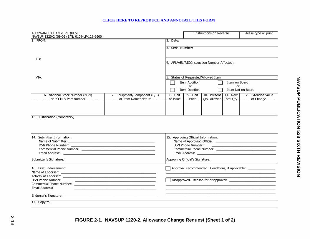
NA
VS
UP
PU
BL
ICA
TIO
N 53
8 SIX
TH
RE
VIS
ION
2-1
3 FIGURE 2-1. NAVSUP 1220-2, Allowance Change Request (Sheet 1 of 2)
ALLOWANCE CHANGE REQUEST Instructions on Reverse Please type or printNAVSUP 1220-2 (09-03) S/N: 0108-LF-128-56001. FROM: 2. Date:
3. Serial Number:
TO:4. APL/AEL/RIC/Instruction Number Affected:
VIA: 5. Status of Requested/Allowed Item
Item Addition Item on Boardor or
Item Deletion Item Not on Board
6. National Stock Number (NSN) 7. Equipment/Component (E/C) 8. Unit 9. Unit 10. Present 11. New 12. Extended Valueor FSCM & Part Number or Item Nomenclature of Issue Price Qty. Allowed Total Qty. of Change
13. Justification (Mandatory)
14. Submitter Information: 15. Approving Official Information: Name of Submitter: ________________________________________________ Name of Approving Official: __________________________________ DSN Phone Number: _______________________________________________ DSN Phone Number: ____________________________________ Commercial Phone Number: _________________________________________ Commercial Phone Number: _________________________________ Email Address: ___________________________________________________ Email Address: ____________________________________________
Submitter's Signature: Approving Official's Signature:
16. First Endorsement: Approval Recommended. Conditions, if applicable: _______________Name of Endorser: _____________________________________________________ _____________________________________________________________Activity of Endorser: ____________________________________________________ _____________________________________________________________DSN Phone Number: _____________________________________________ Disapproved. Reason for disapproval: __________________________Commercial Phone Number: _____________________________________________ _____________________________________________________________Email Address: ______________________________________________ _____________________________________________________________
_____________________________________________________________Endorser's Signature: ___________________________________________________ _____________________________________________________________
17. Copy to:
CLICK HERE TO REPRODUCE AND ANNOTATE THIS FORM

NAVSUP PUBLICATION 538 SIXTH REVISION
2-14
FIGURE 2-1. NAVSUP 1220-2, Allowance Change Request (Sheet 2 of 2)
Instructions for Preparing Allowance Change Request (ACR)
Block 1. ADDRESSEE: Complete in the same manner as other official correspondence.Block 2. DATE: Current date.Block 3. SERIAL NUMBER: The Serial Number shall include the ship type/hull number of the ship or Unit
Identification Code of the activity and a sequential number. Block 4. APL/AEL/RIC/INSTRUCTION NUMBER AFFECTED: Enter the affected Allowance Parts List (APL),
Allowance Equipage List (AEL), Repairable Item Code (RIC), or Instruction Number in this block.Block 5. STATUS OF REQUESTED/ALLOWED ITEM: Place an "x" in the appropriate box(es) to show the
status of the requested/allowed item(s).Block 6. NATIONAL STOCK NUMBER (NSN) OR FSCM AND PART NUMBER: Enter the NSN or the FSCM and
manufacturer's part number. FSCMs are to be written in accordance with DOD publications H4-1 or H4-2 (Federal Supply Codes for Manufacturers).
Block 7. EQUIPMENT/COMPONENT (E/C) OR ITEM NOMENCLATURE: Enter nomenclature for each stock number or part number listed in Block 6. Provide nameplate description and all availabletechnical data. If the item listed is a repair part and the APL/AEL/RIC number for the parentequipment/component is not provided in Block 4, give nameplate data, if available, or as a minimum, manufacturer's name, item name, drawing or reference number, applicable technicalmanual and the service application, system, or subsystem of the equipment which the repair part supports. (If additional space is required, use Block 13 or separate page.)
Block 8. UNIT OF ISSUE (U/I): Enter the approved abbreviation for each standard item, as listed in theNavy Management Data List (NMDL). For non-standard items, use the manufacturer's parts listU/I Data. If the U/I is unknown, leave this blank.
Block 9. UNIT PRICE: Enter the unit price for each item listed.Block 10. PRESENT QUANTITY ALLOWED: Enter present quantity allowed (authorized). Cite source and
date of allowance document in Block 13.Block 11. NEW TOTAL QUANTITY: Enter the total of the present quantity allowed and the additional
quantity requested.Block 12. EXTENDED VALUE OF CHANGE: New total quantity less present quantity allowed times Unit Price.
(Not required for decreases.)Block 13. JUSTIFICATION: Indicate authority for present quantity allowed (Block 10) and reason for
requesting change. Completion of this block is mandatory.Block 14. SUBMITTER INFORMATION: Provide submitter's name, DSN and Commercial Telephone
Number, email address and signature.Block 15. APPROVING OFFICIAL INFORMATION: Provide approving official's name, DSN and Commercial
Telephone Number, email address and signature. Sign in same manner as other officialcorrespondence.
Block 16. FIRST ENDORSEMENT: Provide endorser's name, activity, DSN and Commercial TelephoneNumber, email address and signature. Sign in same manner as other official correspondence.Identify approval or disapproval and provide comments as necessary. Type Commander'sendorsement should include applicability to other ships and such other information which willassist in further consideration of the request.
Block 17. COPY TO: Enter abbreviated titles and codes. Addresses are not necessary unless they arenot available in the SNDL.
NAVSUP 1220-2 (09-03)S/N 0108-LF-128-5600
NAVSUP PUBLICATION 538 SIXTH REVISION
2-15
2-3.5. OTHER REQUIREMENTS. Requirements will also be substantiated and detailed for specially protected equipment designated for use in an atmosphere containing a high concentration of abrasive material. All special features will be thoroughly described. Augmentation of equipment will only be effected when an increase in allowance has been approved and funds are secured. MHE users will receive MHE to fill funded allowances for replacement, via their respective NAVSUP FLC Regional Manager or direct vendor delivery.
2-4. NEW OR SLEP EQUIPMENT
Upon receipt of new MHE/SMSE from direct vendor delivery or a SLEP unit from a SLEP facility, the receiving activity will submit a DD Form 1342, “DOD Property Record”, figure 2-2, or written confirmation to NAVSUP WSS with a copy to the respective NAVSUP FLC Regional Manager. This form or written confirmation must contain the USN registration number, manufacturer serial number, capacity, contract number, and the activity’s name, address, Unit Identification Code (UIC) and point of contact. The receiving activity must perform an initial receipt inspection and preliminary servicing for each piece of MHE/SMSE as described in paragraph 8-4.
2-5. REPLACEMENT UNITS
Funding for replacement MHE/SMSE shall be in accordance with NAVSUPINST 10490.33 (series). With the implementation of the SLEP, MHE is first considered for replacement at a minimum of 8 years after original manufacture or last SLEP. However, depending on utilization, availability of repair parts or extenuating circumstances, the replacement cycle will be adjusted accordingly. Users will submit a written request to the NAVSUP FLC Regional Manager, citing USN number of the unit to be replaced and indicate if identical, similar or non-identical replacement is required. Upon request from the NAVSUP FLC Regional Manager, users will provide additional information as stated below, where applicable. Replacement SMSE units will be centrally managed and coordinated through NAVSUP WSS
2-5.1. SIMILAR UNITS. If a similar replacement MHE unit is required with the same Equipment Cost Code (ECC) and lifting capacity, but with minor modifications/variations from the unit being replaced, cite applicable differences.
2-5.2. NON-IDENTICAL UNITS. If a non-identical replacement MHE unit is required, the ECC, lifting capacity, minimum lift height, and any other unique features must be indicated on the request. Additionally, if this type of unit is not included in the current MHE allowance, the requesting activity will submit an ACR to NAVSUP WSS in accordance with the requirements found in paragraph 2-3.3.
NOTE
Refer to the "Repair Time Standards Supplement" for the respective ECC’s assigned to MHE.
2-5.3. CANNIBALIZATION. No cannibalization of any MHE or SMSE shall be done prior to turn-in to the NAVSUP FLC Regional Manager. Users will be responsible for funding any missing parts. Refer to paragraph 2-8 for additional cannibalization requirements.

NAVSUP PUBLICATION 538 SIXTH REVISION
2-16
2-5.4. NWCF FUNDING. Funding for new replacement MHE from NWCF activities shall be forwarded to NAVSUP WSS for procurement.
2-6. RENTAL/LEASING OF OPERATING EQUIPMENT
All rental or leased agreements will be coordinated through the NAVSUP FLC Regional Manager. All costs are the responsibility of the requesting activity. Prior to approving long-term rental or lease of equipment (in excess of one year), the NAVSUP FLC Regional Manager will coordinate with NAVSUP WSS to investigate alternate methods of satisfying requirements, such as reassignments, loan, consignment from procurement, or repair of dead-lined equipment through a contract or in-house services. Requests for authorization to rent or lease MHE or SMSE should include the following:
a. The desired quantities by type of equipment.
b. The expected duration of the proposed lease or rental arrangement.
c. The monthly cost per unit.
d. The intended application.
e. The reason for leasing.
f. The anticipated annual use in hours.
g. The condition, status and use of similar equipment on board.
2-6.1. OPN FUNDED ACTIVITIES. The following leasing policy applies to activities that use OPN funds:
a. MHE/SMSE is a centrally funded and managed program. Due to this centralization, MHE/SMSE is assigned to each individual operating activity based on their established allowance. This negates any requirement for loaning or leasing equipment among OPN activities.
b. Each activity is authorized to assign MHE/SMSE internally as needed to accomplish or fulfill overall mission requirements.
c. OPN activities are not authorized to establish pools of MHE or SMSE for the purpose of leasing equipment to any other activities.
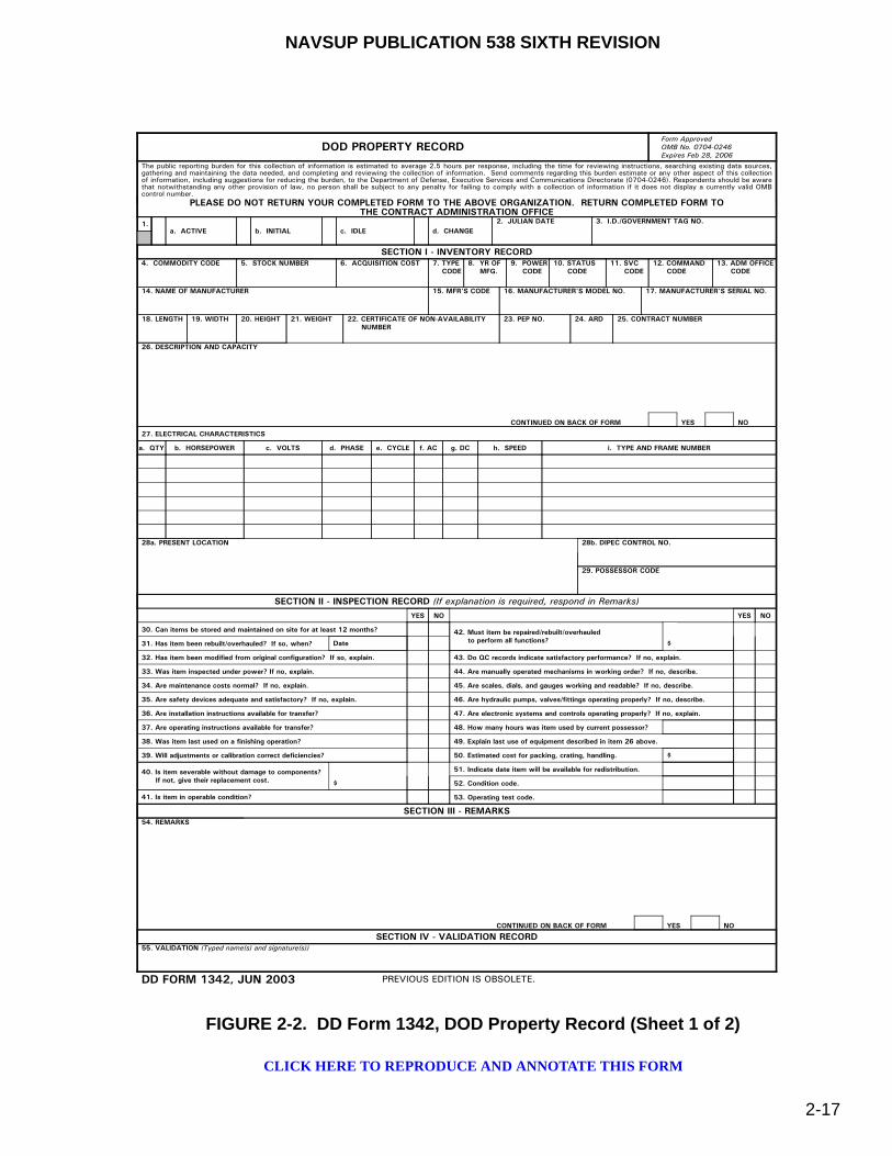
NAVSUP PUBLICATION 538 SIXTH REVISION
2-17
FIGURE 2-2. DD Form 1342, DOD Property Record (Sheet 1 of 2)
DOD PROPERTY RECORDForm ApprovedOMB No. 0704-0246Expires Feb 28, 2006
1.a. ACTIVE b. INITIAL c. IDLE d. CHANGE
2. JULIAN DATE 3. I.D./GOVERNMENT TAG NO.
SECTION I - INVENTORY RECORD4. COMMODITY CODE 5. STOCK NUMBER 6. ACQUISITION COST 7. TYPE
CODE8. YR OF MFG.
9. POWER CODE
10. STATUS CODE
11. SVC CODE
12. COMMAND CODE
13. ADM OFFICE CODE
14. NAME OF MANUFACTURER 15. MFR'S CODE 16. MANUFACTURER'S MODEL NO. 17. MANUFACTURER'S SERIAL NO.
18. LENGTH 19. WIDTH 20. HEIGHT 21. WEIGHT 22. CERTIFICATE OF NON-AVAILABILITY NUMBER
23. PEP NO. 24. ARD 25. CONTRACT NUMBER
26. DESCRIPTION AND CAPACITY
CONTINUED ON BACK OF FORM YES NO
27. ELECTRICAL CHARACTERISTICS
a. QTY b. HORSEPOWER c. VOLTS d. PHASE e. CYCLE f. AC g. DC h. SPEED i. TYPE AND FRAME NUMBER
28a. PRESENT LOCATION 28b. DIPEC CONTROL NO.
29. POSSESSOR CODE
SECTION II - INSPECTION RECORD (If explanation is required, respond in Remarks)YES NO YES NO
30. Can items be stored and maintained on site for at least 12 months?
31. Has item been rebuilt/overhauled? If so, when?
32. Has item been modified from original configuration? If so, explain.
33. Was item inspected under power? If no, explain.
34. Are maintenance costs normal? If no, explain.
35. Are safety devices adequate and satisfactory? If no, explain.
36. Are installation instructions available for transfer?
37. Are operating instructions available for transfer?
38. Was item last used on a finishing operation?
39. Will adjustments or calibration correct deficiencies?
43. Do QC records indicate satisfactory performance? If no, explain.
44. Are manually operated mechanisms in working order? If no, describe.
45. Are scales, dials, and gauges working and readable? If no, describe.
46. Are hydraulic pumps, valves/fittings operating properly? If no, describe.
47. Are electronic systems and controls operating properly? If no, explain.
48. How many hours was item used by current possessor?
49. Explain last use of equipment described in item 26 above.
50. Estimated cost for packing, crating, handling.
51. Indicate date item will be available for redistribution.
52. Condition code.
53. Operating test code.
42. Must item be repaired/rebuilt/overhauled to perform all functions?Date
40. Is item severable without damage to components? If not, give their replacement cost. $
41. Is item in operable condition?
$
$
SECTION III - REMARKS54. REMARKS
CONTINUED ON BACK OF FORM YES NO
SECTION IV - VALIDATION RECORD55. VALIDATION (Typed name(s) and signature(s))
DD FORM 1342, JUN 2003 PREVIOUS EDITION IS OBSOLETE.
The public reporting burden for this collection of information is estimated to average 2.5 hours per response, including the time for reviewing instructions, searching existing data sources,gathering and maintaining the data needed, and completing and reviewing the collection of information. Send comments regarding this burden estimate or any other aspect of this collectionof information, including suggestions for reducing the burden, to the Department of Defense, Executive Services and Communications Directorate (0704-0246). Respondents should be awarethat notwithstanding any other provision of law, no person shall be subject to any penalty for failing to comply with a collection of information if it does not display a currently valid OMBcontrol number.
PLEASE DO NOT RETURN YOUR COMPLETED FORM TO THE ABOVE ORGANIZATION. RETURN COMPLETED FORM TOTHE CONTRACT ADMINISTRATION OFFICE
CLICK HERE TO REPRODUCE AND ANNOTATE THIS FORM
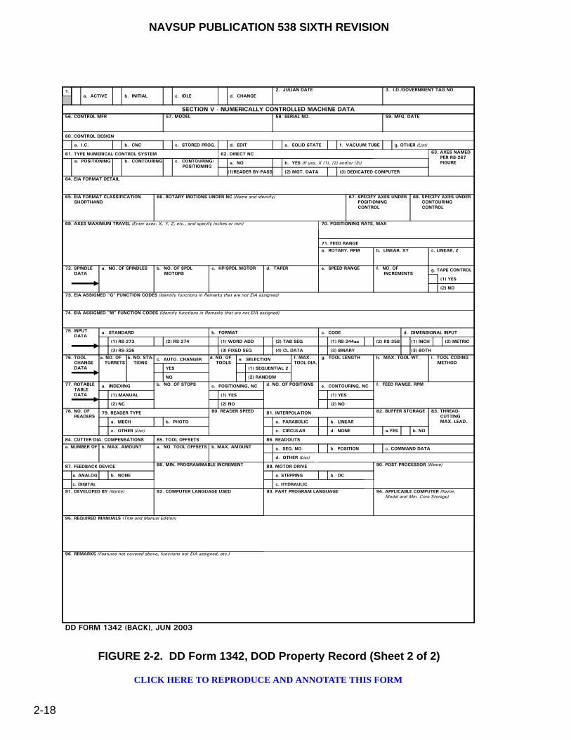
NAVSUP PUBLICATION 538 SIXTH REVISION
2-18
FIGURE 2-2. DD Form 1342, DOD Property Record (Sheet 2 of 2)
1.a. ACTIVE b. INITIAL c. IDLE d. CHANGE
2. JULIAN DATE 3. I.D./GOVERNMENT TAG NO.
SECTION V - NUMERICALLY CONTROLLED MACHINE DATA56. CONTROL MFR 57. MODEL 58. SERIAL NO. 59. MFG. DATE
60. CONTROL DESIGN
a. I.C. b. CNC c. STORED PROG. d. EDIT e. SOLID STATE f. VACUUM TUBE g. OTHER (List)
61. TYPE NUMERICAL CONTROL SYSTEM
a. POSITIONING b. CONTOURING c. CONTOURING/ POSITIONING
a. NO b. YES (If yes, X (1), (2) and/or (3))
(3) DEDICATED COMPUTER
62. DIRECT NC
(1)READER BY-PASS (2) MGT. DATA
63. AXES NAMED PER RS-267 FIGURE
64. EIA FORMAT DETAIL
65. EIA FORMAT CLASSIFICATION SHORTHAND
66. ROTARY MOTIONS UNDER NC (Name and identify) 67. SPECIFY AXES UNDER POSITIONING CONTROL
68. SPECIFY AXES UNDER CONTOURING CONTROL
69. AXES MAXIMUM TRAVEL (Enter axes: X, Y, Z, etc., and specify inches or mm) 70. POSITIONING RATE, MAX
71. FEED RANGE
a. ROTARY, RPM b. LINEAR, XY c. LINEAR, Z
72. SPINDLE DATA
a. NO. OF SPINDLES b. NO. OF SPDL MOTORS
c. HP/SPDL MOTOR d. TAPER e. SPEED RANGE f. NO. OF INCREMENTS
(1) YES
(2) NO
g. TAPE CONTROL
73. EIA ASSIGNED "G" FUNCTION CODES (Identify functions in Remarks that are not EIA assigned)
74. EIA ASSIGNED "M" FUNCTION CODES (Identify functions in Remarks that are not EIA assigned)
75. INPUT DATA
a. STANDARD
(1) RS-273 (2) RS-274
(3) RS-326
b. FORMAT
(1) WORD ADD (2) TAB SEQ
(3) FIXED SEQ (4) CL DATA
c. CODE
(1) RS-244aa (2) RS-358
(3) BINARY
d. DIMENSIONAL INPUT
(1) INCH (2) METRIC
(3) BOTH
76. TOOL CHANGE DATA
c. AUTO. CHANGER
YES
NO
a. NO. OF TURRETS
b. NO. STA- TIONS
e. SELECTION
(1) SEQUENTIAL 2
(2) RANDOM
d. NO. OF TOOLS
f. MAX.TOOL DIA.
g. TOOL LENGTH h. MAX. TOOL WT. i. TOOL CODING METHOD
77. ROTABLE TABLE DATA
a. INDEXING
(1) MANUAL
(2) NC
b. NO. OF STOPS c. POSITIONING, NC
(1) YES
(2) NO
d. NO. OF POSITIONS e. CONTOURING, NC
(1) YES
(2) NO
f. FEED RANGE: RPM
78. NO. OF READERS
79. READER TYPE
a. MECH b. PHOTO
c. OTHER (List)
81. INTERPOLATION
a. PARABOLIC b. LINEAR
c. CIRCULAR d. NONE
80. READER SPEED 82. BUFFER STORAGE
a.YES b. NO
83. THREAD- CUTTING MAX. LEAD.
84. CUTTER DIA. COMPENSATIONS
a. NUMBER OF b. MAX. AMOUNT
85. TOOL OFFSETS
a. NO. TOOL OFFSETS b. MAX. AMOUNT
86. READOUTS
a. SEQ. NO. b. POSITION c. COMMAND DATA
d. OTHER (List)
87. FEEDBACK DEVICE
a. ANALOG b. NONE
c. DIGITAL
88. MIN. PROGRAMMABLE INCREMENT 89. MOTOR DRIVE
a. STEPPING b. DC
c. HYDRAULIC
90. POST PROCESSOR (Name)
91. DEVELOPED BY (Name) 92. COMPUTER LANGUAGE USED 93. PART PROGRAM LANGUAGE 94. APPLICABLE COMPUTER (Name, Model and Min. Core Storage)
95. REQUIRED MANUALS (Title and Manual Edition)
96. REMARKS (Features not covered above, functions not EIA assigned, etc.)
DD FORM 1342 (BACK), JUN 2003
CLICK HERE TO REPRODUCE AND ANNOTATE THIS FORM
NAVSUP PUBLICATION 538 SIXTH REVISION
2-19
d. Leasing Durations.
(1) For leasing requirements less than 30 days per year, the NAVSUP FLC Regional Manager may loan units, if available, from the respective OPN MHE/SMSE pool at cost or can recommend commercial lease (for MHE only), depending on the best economic alternative.
(2) For leasing requirements greater than 30 days, but less than 1 year, commercial leasing will be used.
(3) For leasing requirements in excess of a 1 year commercial lease, the respective activity should consider establishing their own equipment allowance in accordance with NAVICPINST 10490.4 (series).
2-6.2. NWCF AND SPECIAL FUNDED PROGRAM ACTIVITIES. The following leasing policy applies to NWCF and special funded program activities:
a. Each activity is authorized to assign MHE internally as needed to accomplish or fulfill the overall mission requirements.
b. Current local activity leasing guidelines still apply, but if you intend to lease to other activities, you are required to recoup adequate funding to replace your own MHE.
c. Leasing Durations.
(1) For emergency lease requirements of less than 14 days per year, the NAVSUP FLC Regional Manager may loan units, if available, from their respective OPN MHE pool at cost or can recommend commercial lease, depending on best economic alternative.
(2) For lease requirements greater than 14 days, but less than 1 year, commercial leasing will be used.
(3) For lease requirements in excess of 1 year, commercial lease is required, or the respective activity should consider establishing their own MHE allowance in accordance with NAVICPINST 10490.4 (series).
2-6.3. NAVSUP FLC REGIONAL MANAGER LEASING GUIDELINES. The following leasing guidelines apply to each NAVSUP FLC Regional Manager:
a. The regional manager will maintain a small MHE/SMSE pool to assist customers and/or to support the operation of the MHE SLEP Program. The actual required pool size will be coordinated and approved by NAVSUP WSS. The pool will consist of MHE/SMSE separate from any of the NAVSUP FLC’s own equipment assets.
b. The regional manager will follow the leasing guidelines established for each type of funding customer cited in paragraphs 2-6.1 and 2-6.2, including their own NAVSUP FLC operations which follow and are under NWCF guidelines.
NAVSUP PUBLICATION 538 SIXTH REVISION
2-20
c. Lease rate charged to customers should include non-warranty maintenance costs for MHE or SMSE while in their custody and may include a NAVSUP FLC administrative surcharge. No pro-rated equipment replacement fees are authorized.
d. If the leaser is an U.S. Navy activity and has a continuing requirement for MHE, they should consider establishing their own separate equipment allowances in accordance with NAVICPINST 10490.4 (series). The regional manager will coordinate with NAVSUP WSS to investigate alternate methods of satisfying requirements, such a reassignments of excess equipment, re-consignments from procurement, or repair/SLEP of dead-lined equipment.
e. Lease periods may be extended if a requesting activity has inducted MHE into the SLEP Program and is awaiting the return of the unit so they can return the leased MHE.
2-7. MODIFICATIONS OR ALTERATIONS
MHE or SMSE may only be modified or altered using the means outlined in this paragraph. Equipment shall not be modified or altered in any other way without obtaining written approval from the Program Manager at NAVSUP WSS (Code 8341). A copy of the proposed modification or alteration shall be forwarded to the Naval PHST Center (Code G1). Ships desiring to modify or alter an item to increase its use or effectiveness shall submit a justification for the proposed modification or alteration to the Program Manager at NAVSUP WSS and the Naval PHST Center, via appropriate TYCOM, citing in detail the benefits to be obtained. As part of this justification, ships will include a drawing of the proposed modification or alteration to permit review of feasibility and operational safety. In critical or emergency situations, MHE/SMSE assigned to forces afloat may be modified, with the CO/OIC’s written approval, without prior NAVSUP WSS/Naval PHST Center approval to meet urgent operational requirements. Justification and details of the modifications will be furnished to NAVSUP WSS and the Naval PHST Center as soon as practical. Upon receipt of approval, activities shall file a copy in the equipment history file with the record copy of the Shop Repair Order (SRO) or Equipment Repair Order (ERO) used in accomplishing the approved modification or alteration.
2-8. CANNIBALIZATION
Cannibalization of MHE/SMSE is not authorized, except for under the following conditions:
2-8.1. NAVSUP FLC REGIONAL MANAGER. Upon approval by NAVSUP WSS for disposal/cannibalization, the respective NAVSUP FLC Regional Manager may cannibalize equipment without any further approvals to support the SLEP program or the periodic maintenance requirements of MHE/SMSE. All cannibalized units will have the USN registration number removed.
2-8.2. AFLOAT. When operational circumstances dictate, deployed ships are authorized to temporarily cannibalize MHE/SMSE. However, ships must replace all cannibalized parts prior to turn-in to the appropriate NAVSUP FLC Regional Manager. Upon approval by NAVSUP WSS, afloat MHE stored ashore may be cannibalized to keep other shipboard MHE operating. Ships will be responsible for funding any missing parts.
NAVSUP PUBLICATION 538 SIXTH REVISION
2-21
2-9. U.S. NAVY (USN) REGISTRATION NUMBERS
All MHE and SMSE is identified by a unique 7-digit USN registration number assigned by NAVSUP WSS and is not to be duplicated throughout the Navy inventory. For MHE units, the USN registration number is painted on each side of the mast and the body of the equipment where applicable. For SMSE units, the USN registration number is painted on each side of the equipment. The number usually starts with 01, 11, 12, 13, 14, 15, 16, 18, 19, 54, 55 or 57 depending on the type of equipment. When equipment is received without an USN registration number, the receiving activity will forward a letter or a DOD Property Record (DD Form 1342), figure 2-2, to NAVSUP WSS containing the following appropriate descriptive data:
a. Type of equipment (e.g., forklift truck, pallet truck, tow tractor, deck scrubber, etc.).
b. Equipment Cost Codes for Maintenance (refer to the "Repair Time Standards Supplement").
c. Type of power (e.g., diesel, gas, electric, dual fuel, etc.) and applicable safety rating (e.g., EE, EX, DS, etc.). For electric MHE, provide data on the battery.
d. Rated capacity (safe working load) in terms of pounds and load center.
e. Maximum lift height.
f. Collapsed mast height.
g. Manufacturer and nameplate data on the equipment.
h. Model number.
i. Manufacturer’s chassis serial number.
j. Year of manufacture.
k. Acquisition Cost.
l. Contract or document number under which the MHE/SMSE was delivered (also cite shipment number, Government Bill of Lading (GBL), and date shipped from DD Form 250, figure 6-2, if available).
m. Test data (e.g., First Article Test, Hi-Shock Test, or proof of safety certification from an accredited laboratory, as stated in paragraph 5-7d) required for certification of shipboard MHE or SMSE.
n. Copy of the technical manual.
o. Activity assigned custody to include activity name, UIC, activity point of contact, code and telephone number.
NAVSUP PUBLICATION 538 SIXTH REVISION
2-22
After assignment of a USN registration number, NAVSUP WSS will advise the requesting activity and the respective NAVSUP FLC Regional Manager. The requesting activity is responsible for marking the assigned USN registration number on the unit as directed.
2-10. BUDGETING AND FUNDING
2-10.1. INVESTMENT. The NAVSUPSYSCOM MHE/SMSE Program Office is responsible for replacement budgeting of equipment for OPN funded activities. The Program Manager initiates the acquisition process for the procurement of equipment under established applicable procurement documents, such as CID’s/PD’s specifications.
2-10.2. EXPENSE. The appropriate TYCOM or major claimant is responsible for the budgeting of operational and maintenance costs associated with MHE. For SMSE, periodic maintenance (18- and 36-month) requirements are essentially funded by NAVSUP WSS.
2-10.3. SPECIFIC CIRCUMSTANCES. The following shall apply with regard to budgeting and funding for initial requirements, repair/overhaul/preventive maintenance requirements, and NWCF requirements:
a. Initial Requirements. MHE/SMSE requirements in support of new construction, conversion or for increased mission responsibilities will be budgeted and funded by the major claimant/TYCOM having programmatic and functional responsibility for the acquisition of the initial requirements. All requests for new or increased equipment allowances will be submitted to NAVSUP WSS, via the user’s major claimant, as prescribed in paragraphs 2-3.2 and 2-3.3. Upon receipt of approval and funding documentation from the responsible major claimant, NAVSUP WSS will effect procurement of the requested initial requirements.
b. Repair, Overhaul and Preventive Maintenance. Budgeting and funding requests for repair, overhaul, and preventive maintenance of MHE should be submitted to the user’s major claimant in accordance with established local procedures. For SMSE, the 18- and 36-month periodic maintenance requirements are essentially programmed through NAVSUP WSS. All other funding requirements shall be budgeted through the major claimant. Included with submissions should be funding for acquisition of the onboard repair parts required to maintain MHE/SMSE in operable condition.
c. NWCF Requirements. All NWCF activities are responsible for funding SLEP and/or replacements.
2-11. DISPOSITION OF EXCESS AND DISPOSAL OF MHE/SMSE
All requests for the disposition of excess and disposal of MHE/SMSE, afloat or ashore, will be submitted by the activity to the local NAVSUP FLC Regional Manager on a “Report of Excess Personal Property” (Standard Form 120), figure 2-3. Units afloat shall coordinate such efforts with their respective TYCOM. The NAVSUP FLC Regional Manager will then evaluate the request and provide recommendations to NAVSUP WSS for final resolution. In some cases, the equipment may not be needed for shipboard use but would be useful as a shore-based unit which should also be included in the recommendation. In evaluating a request, the NAVSUP FLC Regional Manager should consider the following options:
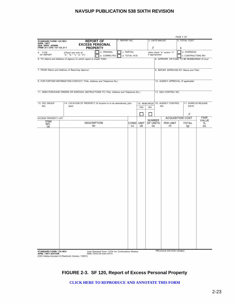
NAVSUP PUBLICATION 538 SIXTH REVISION
2-23
FIGURE 2-3. SF 120, Report of Excess Personal Property
������������� ������
����������
�����������������
����������������������
������
��������������
������
����������� ���� ��� ���� ���� �����
�
�� �����������
������������ ���������������������
�������� �
�����������
���� �� �
���� �����
��������������������� �� ������������
���!���� �
"����� ������!
#��������������������� ������������������������������$�% &�� ������������%����'������'%������� ����
(������������������������ � ������������� )�������� ����!���'�����������!�����
*�������%�$�������� ����� ���!�����������������!��������"� �+�� ����� ����! ���� ������������
���������%��$ ������������������� �����%��������!�����������������!��������"� ������ ���������
��� �������%��
��
��� ��� ���������������� �������������������������#��
�����
�#���������,�
��� �
�&� ����������
���
�(� �%���%������ ���
� �
�-�����������������
�������.
�����������.
�����.
%���.
%�'�����%��
� .
�,%���������
����%��".
� ��/.
� ��! �%�
0�1.
������������� ������
�����������������
�%2 ��3�4��5���657���+ �"65��643849�3864��1 32.��(#�+:++:&��:�+(�
���!��%��������%� '��
� �������
(CDC Adobe Acrobat 4.0 Electronic Version, 1/2001)
//
//
CLICK HERE TO REPRODUCE AND ANNOTATE THIS FORM

NAVSUP PUBLICATION 538 SIXTH REVISION
2-24
a. Unit beyond capability of maintenance and/or not suitable for SLEP. Disposal and/or cannibalization recommended.
b. Viable SLEP and NAVSUP FLC/FICP pool candidate.
c. Viable NAVSUP FLC/FICP pool candidate. No SLEP required (MHE only).
d. Excess to regional requirements.
e. Excess to regional requirements/SLEP required.
f. Other.
Upon receipt of the NAVSUP FLC recommendation, NAVSUP WSS will evaluate and provide written excess turn-in/disposal instructions within 30 days to the activity and the NAVSUP FLC.
2-11.1. EXCESS TURN-IN PROCEDURES. Based on NAVSUP WSS direction, MHE/SMSE shall either be forwarded to the local NAVSUP FLC Regional Manager or to a designated SLEP facility (for MHE only). No cannibalization of equipment shall be performed prior to turn-in to the NAVSUP FLC Regional Manager, except under the conditions outlined in paragraph 2-8. Users will be responsible for funding any missing parts.
2-11.2. DISPOSAL PROCEDURES. Based on NAVSUP WSS’s direction, MHE/SMSE approved for disposal will have the USN registration number removed prior to disposal to avoid accidental reinstatement in the Navy’s inventory. NAVSUP WSS will change the EMACS USN Activity Comment Code field to "z". No cannibalization of equipment shall be performed prior to turn-in to the Defense Reutilization Marketing Office (DRMO) facility, except under the conditions outlined in paragraph 2-8. Users will be responsible for submitting signed copies (by a DRMO official) of the "Issue Release/Receipt Document" (DD Form 1348-1A) to the local NAVSUP FLC Regional Manager and to NAVSUP WSS. Upon receipt of the signed DD Form 1348-1A, NAVSUP WSS will delete the EMACS record and the Enterprise Resource Planning (ERP) program to reflect disposal. NAVSUP WSS will then notify the applicable NAVSUP FLC Regional Manager upon completion of the disposal action.

NAVSUP PUBLICATION 538 SIXTH REVISION
3-1
CHAPTER 3
TYPES OF INDUSTRIAL MATERIALS HANDLING EQUIPMENT
3-1. GENERAL
The various approved types and selected operational safety specifications of industrial materials handling equipment (MHE) and associated forklift truck attachments are described in this chapter. Refer to NAVSEA SW023-AH-WHM-010 for other approved forklift truck attachments specifically designed to handle ammunition and explosives.
3-1.1. NATIONAL FIRE PROTECTION ASSOCIATION (NFPA) DESIGNATIONS. All MHE is identified by alphabetical designators. NFPA definitions of these designators are as follows:
a. Type CN. Compressed natural gas-powered, hard rubber or pneumatic tires, having minimum acceptable safeguards against inherent MHE fire hazards.
b. Type CNS. Type CN MHE with additional safeguards to exhaust, fuel and electrical systems.
c. Type D. Diesel-powered, hard rubber or pneumatic tires, having minimum acceptable safeguards against inherent MHE fire hazards.
d. Type DS. Type D MHE with additional safeguards to exhaust, fuel and electrical systems.
e. Type DY. Type DS MHE that do not have any electrical equipment including the ignition and are equipped with temperature limitation features.
f. Type E. Electrically-powered, hard rubber or pneumatic tires, having minimum acceptable safeguards against inherent and electrical shock hazards.
g. Type EE. Type E MHE with the electric motor and all other electrical components completely enclosed.
h. Type EX. Type EE MHE with the electric motor, all other components, and the fittings designed, constructed, and assembled that they may be used in atmospheres containing specially named flammable vapors, dusts, and under certain conditions, fibers. Type EX MHE are specifically tested and classified for use in Class I, Group D (atmospheres containing flammable vapors, referred to as “explosion proof”), or for Class II, Group G (atmospheres containing combustible dust, referred to as “ignition proof”) locations as defined in NFPA 70, National Electrical Code (NEC).
i. Type G. Gasoline-powered, hard rubber or pneumatic tires, having minimum acceptable safeguards against inherent MHE fire hazards.

NAVSUP PUBLICATION 538 SIXTH REVISION
3-2
j. Type G/CN. Dual-fuel capable MHE meeting type G or type CN requirements.
k. Type G/LP. Dual-fuel capable MHE meeting type G or type LP requirements.
l. Type GS. Type G MHE having additional safeguards to exhaust, fuel and electrical systems.
m. Type GS/CNS. Dual-fuel capable MHE meeting type GS or type CNS requirements.
n. Type GS/LPS. Dual-fuel capable MHE meeting type GS or type LPS requirements.
o. Type LP. Liquefied petroleum gas-powered, hard rubber or pneumatic tires, and minimum acceptable safeguards against inherent fire hazards.
p. Type LPS. Type LP MHE with additional safeguards to exhaust, fuel and electrical systems.
3-1.2. NAVAL DESIGNATIONS. The Department of Navy (DON) has assigned the following MHE alphabetical designators, which are not official NFPA designators:
3-1.2.1. Manual Pallet Trucks (Afloat). The following descriptions apply to manually-powered pallet trucks approved for use afloat that are managed by NAVSUP Weapon Systems Support (NAVSUP WSS) [formerly Naval Inventory Control Point Mechanicsburg (NAVICP-M)]:
a. Type H. Manually-powered pallet truck modified by the addition of a deadman brake system, salt fog protection, lifting points, tiedown points and shock hardening features. They are available through the Fleet Issue Control Point (FICP) and are marked with a USN registration number.
b. Type HS. Type H pallet truck modified by the addition of hard/solid non-sparking wheels and a means to dissipate static electric charges, minimally two ground straps or two conductive wheels/tires. They are available through the FICP and are marked with a USN registration number.
3-1.2.2. Manual Pallet Trucks (Ashore). The following descriptions apply to manually-powered pallet trucks approved for use ashore only (shall not be used afloat) and are not managed by NAVSUP WSS:
a. General Supply. Manually-powered pallet truck with solid wheels/tires that are locally procured.
b. Ordnance. A general supply pallet truck modified by the addition of hard/solid non-sparking wheels and a means to dissipate static electric charges, minimally two ground straps or two conductive wheels/tires.
3-1.3. NON-DESIGNATIONS. The following MHE do not have an assigned NFPA or Naval designation.
3-1.3.1. Mobile Cargo Cranes. Mobile, diesel-powered cargo cranes used ashore and afloat having safeguards to exhaust, fuel and electrical systems.

NAVSUP PUBLICATION 538 SIXTH REVISION
3-3
3-1.3.2. Aerial Work Platforms. Boom-lift platforms and scissor-lift platforms are shipboard or shore based aerial work platforms containing safeguards to personnel safety.
3-1.3.3. Diesel Conveyor Belt Vehicles. Portable, diesel-powered conveyor belt vehicles used ashore with safeguards to exhaust, fuel and electrical systems.
3-2. FORKLIFT TRUCKS
There are several kinds of approved forklift trucks available for use. Forklift trucks are mobile wheeled units used to load, lift, and transport different items. Forklifts come equipped with two forks which are secured to the supporting frame. The forks and frame are located in the front of the truck, with the exception of sideloading trucks. Forks move vertically on the supporting frame and can be tilted forward to pick up a load, and backward to stabilize the load. Several attachments are available for use with forklifts and will be presented within this chapter. Shipboard forklift trucks are procured by NAVSUP WSS using Commercial Item Descriptions (CID’s) or Purchase Descriptions (PD’s) that contain additional/unique safety requirements such as all-wheel braking, additional stability tests, and shipboard shock qualifications. Shipboard forklift trucks are procured by NAVSUP WSS using Commercial Item Descriptions (CID’s) or Purchase Descriptions (PD’s), which are identified in paragraph A-2.8.2. Table 3-1 identifies the minimum requirements necessary to qualify forklift trucks as shipboard approved.
Forklift trucks may be powered by batteries, gasoline, liquid propane gas, diesel or compressed natural gas. They may have pneumatic tires for use over rough terrain, or solid rubber tires for use over smooth and hard surfaces. Specific safety features are built into each type of MHE that allow for safe operations in a variety of areas where ammunition and explosives are present. Spark-enclosed (EE) trucks have provisions to ensure that no spark will escape the generator, motor, or switches. Explosion-Proof (EX) trucks are fully enclosed to prevent energy, such as an electrical spark or heat from accidentally escaping to the surrounding atmosphere and initiating an explosion. Type EX trucks come equipped with non-sparking fork coverings. Diesel-powered forklifts are equipped with spark-arresting devices to ensure safe operation in hazardous areas. Also, diesel-powered DY forklifts are equipped with static grounding straps or electrically conductive wheels and tires to discharge any build-up of static electricity.
Compressed natural gas MHE are approved for operational areas ashore as defined in paragraph5-9. Operating areas may be required to be equipped with methane detectors that activate audible and visual alarms prior to reaching the lower explosive limit (LEL). Each activity shall refer to the gas detector’s recommendations to determine the required quantity of gas detectors and the installation locations. The emissions of methane shall be monitored in accordance with the manufacturer’s recommendations to ensure regulatory compliance for safe operation.
3-2.1. STANDARD FORKLIFT TRUCKS. Standard forklift trucks are counterbalanced and are equipped with a lifting mechanism that elevates a fork carriage. Two adjustable forks are secured to the fork carriage. An overhead guard is provided for the operator's safety. Figures 3-1, 3-2, 3-3, 3-4 and 3-5 provide examples of standard forklift trucks.
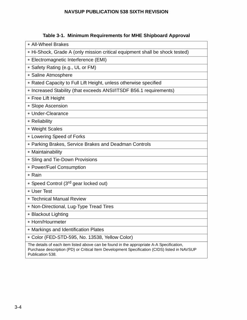
NAVSUP PUBLICATION 538 SIXTH REVISION
3-4
Table 3-1. Minimum Requirements for MHE Shipboard Approval
All-Wheel Brakes
Hi-Shock, Grade A (only mission critical equipment shall be shock tested)
Electromagnetic Interference (EMI)
Safety Rating (e.g., UL or FM)
Saline Atmosphere
Rated Capacity to Full Lift Height, unless otherwise specified
Increased Stability (that exceeds ANSI/ITSDF B56.1 requirements)
Free Lift Height
Slope Ascension
Under-Clearance
Reliability
Weight Scales
Lowering Speed of Forks
Parking Brakes, Service Brakes and Deadman Controls
Maintainability
Sling and Tie-Down Provisions
Power/Fuel Consumption
Rain
Speed Control (3rd gear locked out)
User Test
Technical Manual Review
Non-Directional, Lug-Type Tread Tires
Blackout Lighting
Horn/Hourmeter
Markings and Identification Plates
Color (FED-STD-595, No. 13538, Yellow Color)
The details of each item listed above can be found in the appropriate A-A Specification, Purchase description (PD) or Critical Item Development Specification (CIDS) listed in NAVSUP Publication 538.
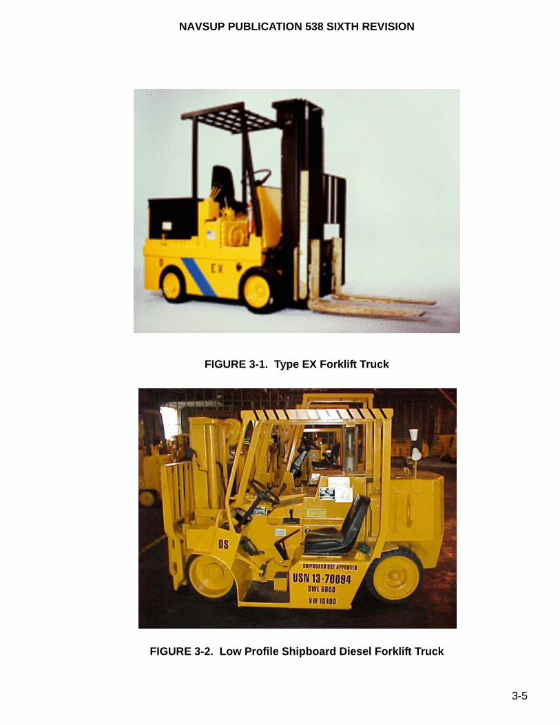
NAVSUP PUBLICATION 538 SIXTH REVISION
3-5
FIGURE 3-1. Type EX Forklift Truck
FIGURE 3-2. Low Profile Shipboard Diesel Forklift Truck
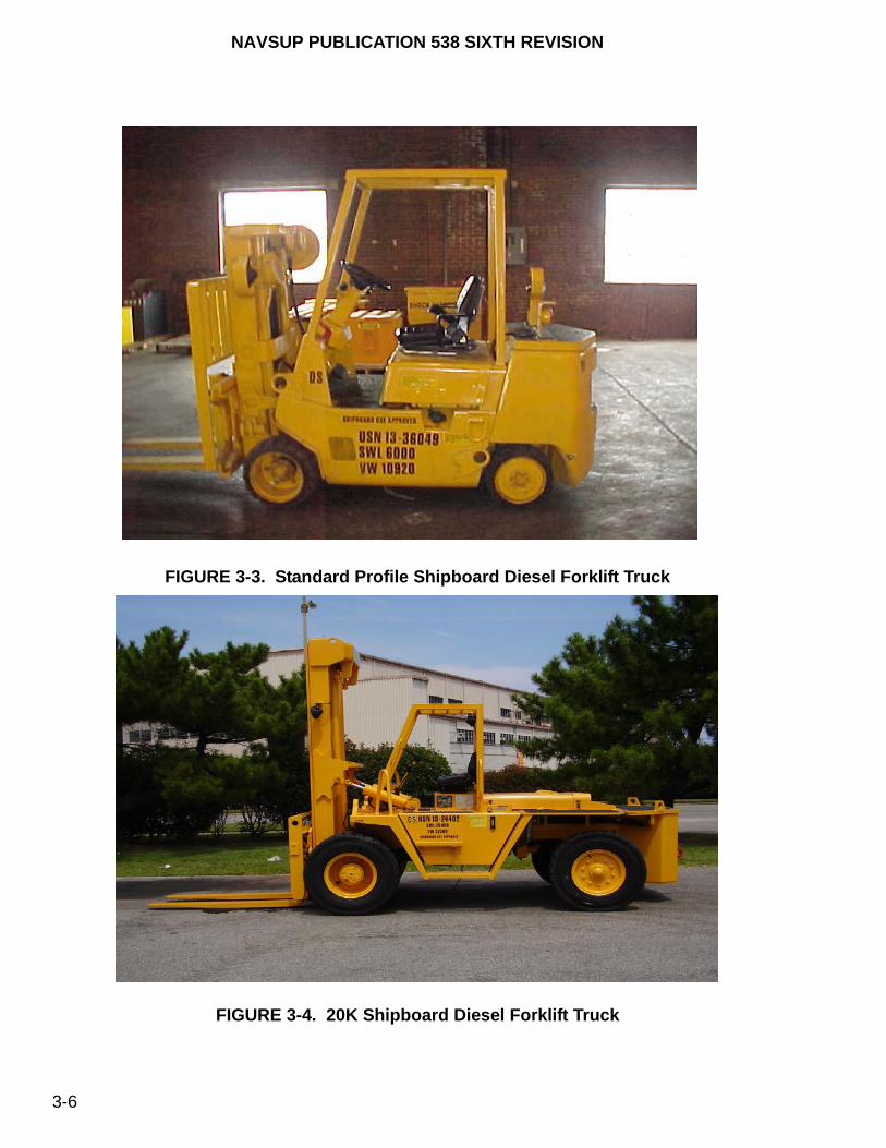
NAVSUP PUBLICATION 538 SIXTH REVISION
3-6
FIGURE 3-3. Standard Profile Shipboard Diesel Forklift Truck
FIGURE 3-4. 20K Shipboard Diesel Forklift Truck

NAVSUP PUBLICATION 538 SIXTH REVISION
3-7
FIGURE 3-5. Typical Electric Forklift Truck
3-2.2. REACHING AND TIERING. This type of forklift truck uses outriggers vice a counterbalance, reducing size and making them suitable for use in confined spaces. The forks, which are mounted on an extendable mechanism, are elevated by means of a lift mechanism. They are electric-powered and have solid tires. Overhead guards are not normally provided on shipboard models (only ashore units). Manufacturer-installed spinner knobs are acceptable for these trucks. Figure 3-6 illustrates a reaching and tiering forklift truck.

NAVSUP PUBLICATION 538 SIXTH REVISION
3-8
FIGURE 3-6. Reaching and Tiering Forklift Truck
3-2.3. SIDELOADER. This type of forklift truck is used to handle long items. They have flatbed platforms at the end. The uprights for carrying the forks are located in the center. The forks elevate up and down on the mast. The forks and the mast also travel in a vertical and horizontal direction. Some models are equipped with auxiliary forks for extra-long load stabilization. The sideloader has solid tires. Figure 3-7 illustrates a sideloader.

NAVSUP PUBLICATION 538 SIXTH REVISION
3-9
FIGURE 3-7. Sideloader
3-2.4. ROUGH TERRAIN. This type of forklift truck is intended for operation on unimproved natural terrain as well as the disturbed terrain of construction sites. These trucks are diesel-powered, two-wheel or four-wheel drive, articulate or rigid frame-type vehicles with pneumatic tires. Rough terrains may be either vertical masts, as shown in figure 3-8, variable reach linkage-type, as shown in figure 3-9, or variable reach boom-type, as shown in figure 3-10.
3-2.5. FRONT/SIDELOADER (SWINGMAST). The front/sideloader, also identified as swingmast, operates as a forklift and sideloader combined. However, most units only swing to one side, usually to the right. Figure 3-11 provides an illustration of a front/sideloader (swingmast). Long loads can be transported parallel to the direction of travel, making them easier to maneuver through narrow doorways and aisles. The truck is available in safe working loads (SWL’s) up to 11,000 pounds. Due to their high wheel loading, front/sideloaders are not approved for shipboard use. This truck is electrically or diesel-engine powered.
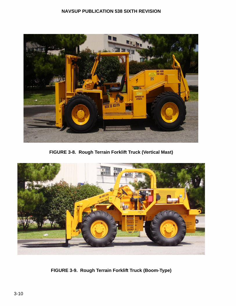
NAVSUP PUBLICATION 538 SIXTH REVISION
3-10
FIGURE 3-8. Rough Terrain Forklift Truck (Vertical Mast)
FIGURE 3-9. Rough Terrain Forklift Truck (Boom-Type)

NAVSUP PUBLICATION 538 SIXTH REVISION
3-11
FIGURE 3-10. Rough Terrain Forklift Truck (Variable Reach Boom-Type)
FIGURE 3-11. Front/Sideloader (Swingmast)
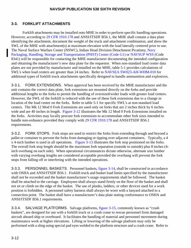
NAVSUP PUBLICATION 538 SIXTH REVISION
3-12
3-3. FORKLIFT ATTACHMENTS
Forklift attachments may be installed onto MHE in order to perform specific handling operations. However, according to 29 CFR 1910.178 and ANSI/ITSDF B56.1, the MHE shall contain a data plate identifying the attachment, document the weight of the truck and attachment combination, and show the SWL of the MHE with attachment(s) at maximum elevation with the load laterally centered prior to use. The Naval Surface Warfare Center (NSWC), Indian Head Division Detachment Picatinny, Navy Packaging, Handling, Storage and Transportation (PHST) Center (Code G1) or NAVSUP WSS (Code 8341) will be responsible for contacting the MHE manufacturer documenting the intended configuration and obtaining the manufacturer’s new data plate for the requestor. When non-standard load center data plates are not provided by manufacturer and installed on the MHE, table 5-1 provides calculations of SWL’s when load centers are greater than 24 inches. Refer to NAVSEA SW023-AH-WHM-010 for additional types of forklift truck attachments specifically designed to handle ammunition and explosives.
3-3.1. FORK EXTENSIONS. When approval has been received by the MHE manufacturer and the unit contains the correct data plate, fork extensions are mounted directly on the forks and provide additional lengths to the forks to permit the handling of oversized/wider loads with greater load centers. However, the SWL of the forklift is reduced with the use of these fork extensions due to a change in location of the load center on the forks. Refer to table 5-1 for specific SWL’s at non-standard load centers. The Mk 12 Mod 0 Fork Extensions are used only on forks that are 2 inches thick by 6 inches wide and are 40 inches in length. Figure 3-12 illustrates the Mk 12 Mod 0 Fork Extensions installed on the forks. Activities may locally procure fork extensions to accommodate other fork sizes intended to handle non-ordnance provided they comply with 29 CFR 1910.178 and ANSI/ITSDF B56.1 requirements.
3-3.2. FORK STOPS. Fork stops are used to restrict the forks from extending through and beyond a pallet or container to prevent the forks from damaging or tipping over adjacent containers. Typically, a 4 x 4-inch lumber is used in all operations. Figure 3-13 illustrates the fork stop positioned on the forks. The overall fork stop length should be the maximum fork separation (outside to outside) plus 8 inches (4-inch overhang on each side). When operational circumstances dictate otherwise, alternate size lumber with varying overhang lengths are considered acceptable provided the overhang will prevent the fork stops from falling off or interfering with the intended operations.
3-3.3. PERSONNEL BASKETS. Personnel baskets, figure 3-14, shall be constructed in accordance with OSHA and ANSI/ITSDF B56.1. Forklift truck and basket load limits specified by the manufacturer shall not be exceeded and the basket manufacturer’s usage requirements shall be followed. The basket shall be attached to the carriage. Employees shall always stand firmly on the floor of the basket and shall not sit or climb on the edge of the basket. The use of planks, ladders, or other devices used for a work position is forbidden. A personnel safety harness shall always be worn with a lanyard attached to a connection point. The basket shall have a manufacturer’s data plate stating conformance to OSHA and ANSI/ITSDF B56.1 requirements.
3-3.4. SALVAGE PLATFORMS. Salvage platforms, figure 3-15, commonly known as “crash baskets”, are designed for use with a forklift truck or a crash crane to rescue personnel from damaged aircraft aboard ship or overboard. It facilitates the handling of material and personnel movement during maintenance work at higher elevations. Lifting or lowering of the salvage platform may only be performed with a sling using special pad eyes welded to the platform structure and a crash crane. Refer to
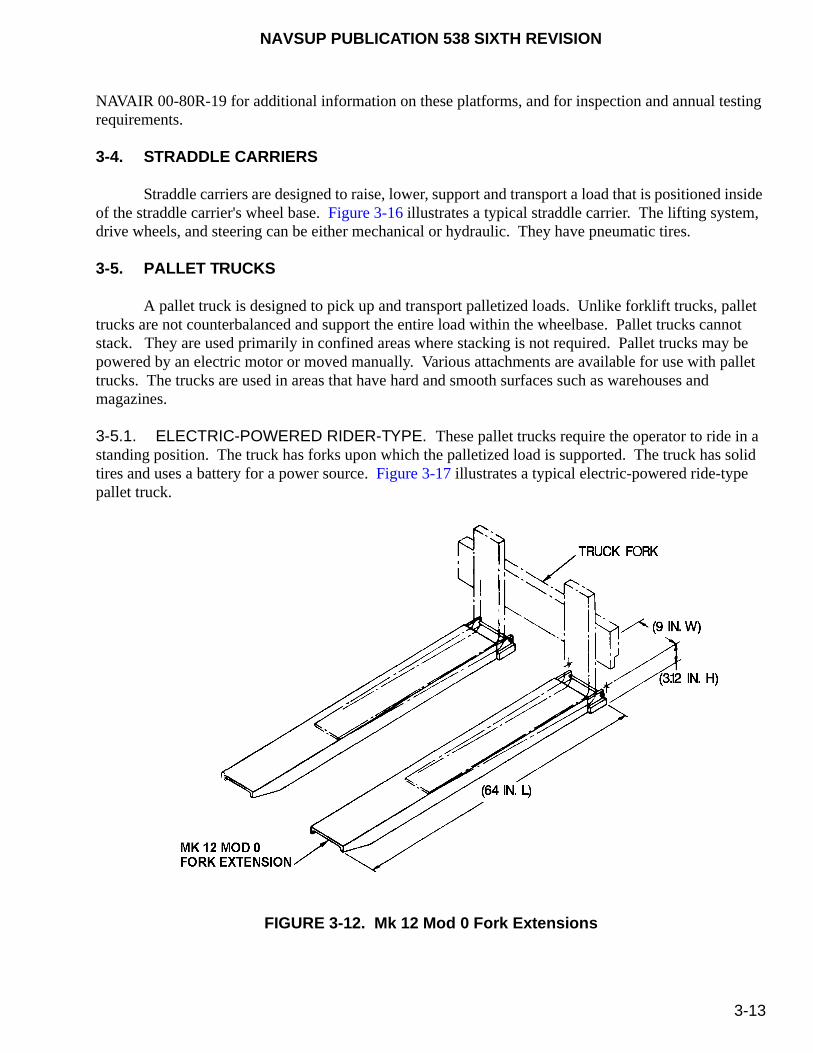
NAVSUP PUBLICATION 538 SIXTH REVISION
3-13
NAVAIR 00-80R-19 for additional information on these platforms, and for inspection and annual testing requirements.
3-4. STRADDLE CARRIERS
Straddle carriers are designed to raise, lower, support and transport a load that is positioned inside of the straddle carrier's wheel base. Figure 3-16 illustrates a typical straddle carrier. The lifting system, drive wheels, and steering can be either mechanical or hydraulic. They have pneumatic tires.
3-5. PALLET TRUCKS
A pallet truck is designed to pick up and transport palletized loads. Unlike forklift trucks, pallet trucks are not counterbalanced and support the entire load within the wheelbase. Pallet trucks cannot stack. They are used primarily in confined areas where stacking is not required. Pallet trucks may be powered by an electric motor or moved manually. Various attachments are available for use with pallet trucks. The trucks are used in areas that have hard and smooth surfaces such as warehouses and magazines.
3-5.1. ELECTRIC-POWERED RIDER-TYPE. These pallet trucks require the operator to ride in a standing position. The truck has forks upon which the palletized load is supported. The truck has solid tires and uses a battery for a power source. Figure 3-17 illustrates a typical electric-powered ride-type pallet truck.
FIGURE 3-12. Mk 12 Mod 0 Fork Extensions
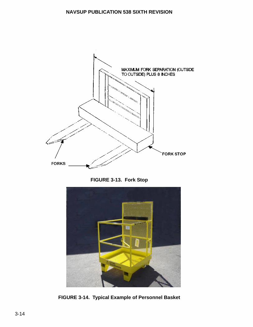
NAVSUP PUBLICATION 538 SIXTH REVISION
3-14
FIGURE 3-13. Fork Stop
FIGURE 3-14. Typical Example of Personnel Basket
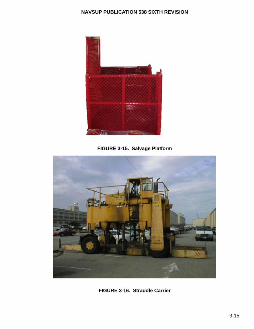
NAVSUP PUBLICATION 538 SIXTH REVISION
3-15
FIGURE 3-15. Salvage Platform
FIGURE 3-16. Straddle Carrier

NAVSUP PUBLICATION 538 SIXTH REVISION
3-16
FIGURE 3-17. Electric-Powered Rider-Type Pallet Truck
FIGURE 3-18. Electric-Powered Walkie-Type Pallet Truck

NAVSUP PUBLICATION 538 SIXTH REVISION
3-17
3-5.2. ELECTRIC-POWERED WALKIE-TYPE. In order to use these pallet trucks, the operator must walk behind the truck while steering by hand. The truck has forks upon which the load is supported. The truck has solid tires and a battery for a power source. Figure 3-18 illustrates a typical electric-powered walkie-type pallet truck.
3-5.3. MANUAL PALLET TRUCKS. These pallet trucks have solid tires, require manual power for locomotion, are equipped with forks that are raised and lowered by a hydraulic or mechanical lift mechanism to support palletized loads, and steering is accomplished by means of a tow handle capable of 90° turns in either direction. Figure 3-19 illustrates a typical manual pallet truck used afloat. Refer to paragraph 3-1.2.1 for descriptions of manual pallet trucks used afloat or to paragraph 3-1.2.2 for descriptions of manual pallet trucks used ashore.
3-6. PLATFORM TRUCKS
Platform trucks, like pallet trucks, are designed to support the load on the wheelbase. However, instead of forks, loads are placed on a platform. Figures 3-20 and 3-21 illustrate a rider-type and walkie-type platform truck, respectively.
FIGURE 3-19. Manual Pallet Truck (Afloat)
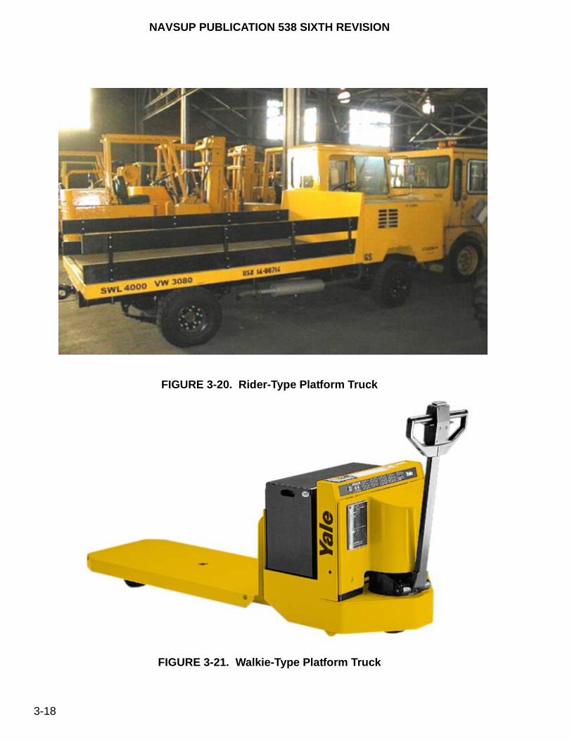
NAVSUP PUBLICATION 538 SIXTH REVISION
3-18
FIGURE 3-20. Rider-Type Platform Truck
FIGURE 3-21. Walkie-Type Platform Truck
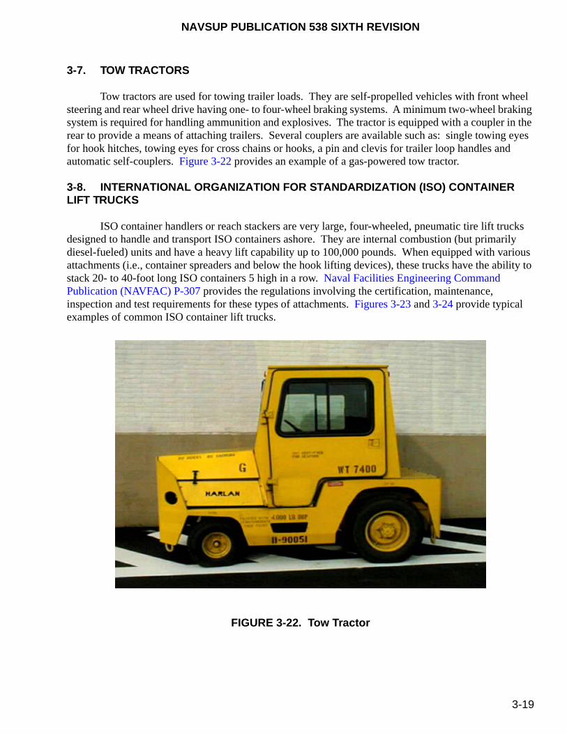
NAVSUP PUBLICATION 538 SIXTH REVISION
3-19
3-7. TOW TRACTORS
Tow tractors are used for towing trailer loads. They are self-propelled vehicles with front wheel steering and rear wheel drive having one- to four-wheel braking systems. A minimum two-wheel braking system is required for handling ammunition and explosives. The tractor is equipped with a coupler in the rear to provide a means of attaching trailers. Several couplers are available such as: single towing eyes for hook hitches, towing eyes for cross chains or hooks, a pin and clevis for trailer loop handles and automatic self-couplers. Figure 3-22 provides an example of a gas-powered tow tractor.
3-8. INTERNATIONAL ORGANIZATION FOR STANDARDIZATION (ISO) CONTAINER LIFT TRUCKS
ISO container handlers or reach stackers are very large, four-wheeled, pneumatic tire lift trucks designed to handle and transport ISO containers ashore. They are internal combustion (but primarily diesel-fueled) units and have a heavy lift capability up to 100,000 pounds. When equipped with various attachments (i.e., container spreaders and below the hook lifting devices), these trucks have the ability to stack 20- to 40-foot long ISO containers 5 high in a row. Naval Facilities Engineering Command Publication (NAVFAC) P-307 provides the regulations involving the certification, maintenance, inspection and test requirements for these types of attachments. Figures 3-23 and 3-24 provide typical examples of common ISO container lift trucks.
FIGURE 3-22. Tow Tractor
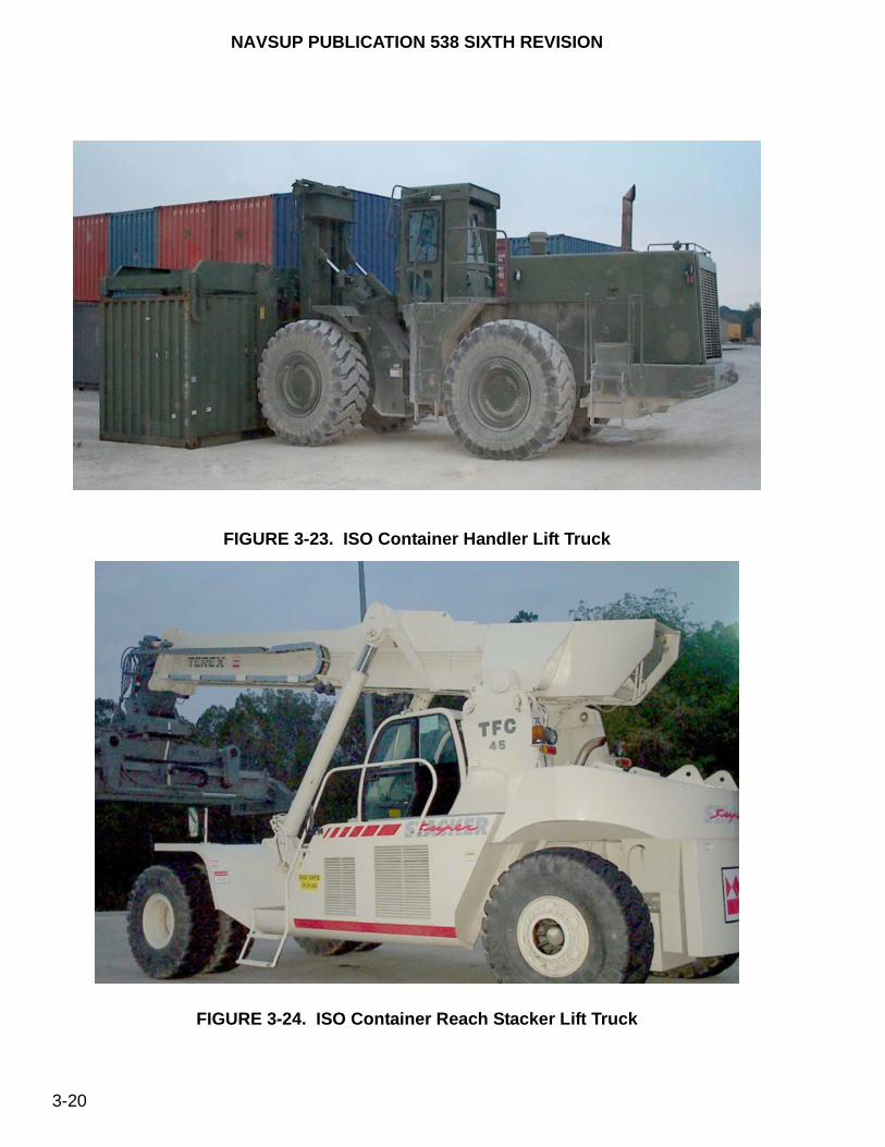
NAVSUP PUBLICATION 538 SIXTH REVISION
3-20
FIGURE 3-23. ISO Container Handler Lift Truck
FIGURE 3-24. ISO Container Reach Stacker Lift Truck

NAVSUP PUBLICATION 538 SIXTH REVISION
3-21
3-9. MOBILE CARGO CRANES
Cargo cranes are mobile, diesel-powered supported by a welded steel frame, with front and rear wheel steering used afloat or ashore. They are equipped with outriggers. The superstructure is capable of rotating 360 degrees. They are intended to hoist or lower general supplies. Additionally, the Grove mobile cargo crane (Model No. YB4410) has also been approved for handling the Rolling Airframe Missile (RAM), NATO Sea Sparrow Missile (NSSM), Evolved Sea Sparrow Missile (ESSM) containers, or palletized loads of Close-In Weapon System (CIWS) into the ship’s sponson. Refer to NAVSEA OP 4 (afloat) or NAVSEA OP 5 (ashore) for regulations and safety precautions involving the handling of ammunition and explosives with these cranes. Shore-based mobile cargo cranes shall follow the requirements of NAVFAC P-307. Figure 3-25 provides an example of a Grove mobile cargo crane (Model No. YB4410).
FIGURE 3-25. Grove Crane (YB4410)
3-10. SHIPBOARD AERIAL WORK PLATFORMS
A minimum of two people (one on the ground/deck and the other in the basket) are required at all times when operating an aerial work platform.
The two types of aerial work platforms that provide reach capability to elevate personnel and offer a platform to perform scheduled maintenance operations are the boom-lift platform and the scissor-lift platform. Currently, shipboard aerial work platform operations are restricted while underway, along the piers, in protected waters and at anchorage. While in-port, they may be used ashore to support ship requirements. They may be used afloat for emergent use only upon the approval from the ship’s Commanding Officer/Officer-in-Charge’s (CO/OIC). When approved, the boom shall be arranged in the athwartship direction, the aerial work platform secured at four points, and the SWL is reduced to 80% (i.e., a unit with a SWL of 500 pounds may be used at only 400 pounds). Personnel shall physically conduct an inspection of the intended travel path prior to moving aerial work platforms for possible hazards (e.g., storm grates/drains, debris, power lines, etc.) as addressed in NAVFAC P-300 (series).
WARNING
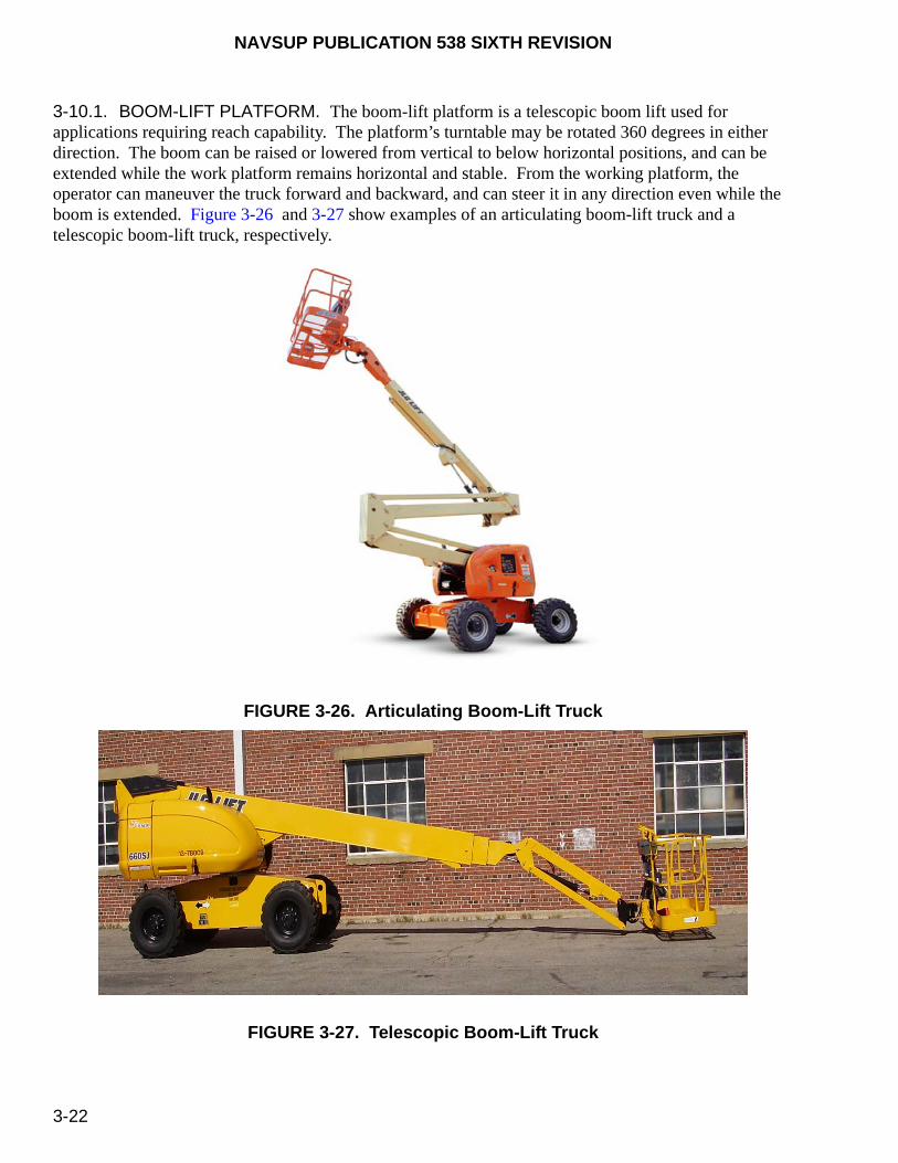
NAVSUP PUBLICATION 538 SIXTH REVISION
3-22
3-10.1. BOOM-LIFT PLATFORM. The boom-lift platform is a telescopic boom lift used for applications requiring reach capability. The platform’s turntable may be rotated 360 degrees in either direction. The boom can be raised or lowered from vertical to below horizontal positions, and can be extended while the work platform remains horizontal and stable. From the working platform, the operator can maneuver the truck forward and backward, and can steer it in any direction even while the boom is extended. Figure 3-26 and 3-27 show examples of an articulating boom-lift truck and a telescopic boom-lift truck, respectively.
FIGURE 3-26. Articulating Boom-Lift Truck
FIGURE 3-27. Telescopic Boom-Lift Truck

NAVSUP PUBLICATION 538 SIXTH REVISION
3-23
3-10.2. SCISSOR-LIFT PLATFORM. The scissor-lift platform consists of a maintenance platform that is used where less reach and height are required. It is designed to provide a larger platform working area and generally accommodates heavier loads than the boom-lift platform. The scissor-lift may be maneuvered in a manner similar to the boom-lift truck, but the work platform can only be raised vertically. Figure 3-28 illustrates a typical scissor-lift platform.
FIGURE 3-28. Scissor-Lift (Raised Position)
3-11. DIESEL CONVEYOR BELT VEHICLES
The diesel conveyor belt vehicle is used by shore activities for general supply loading and unloading of ships. By means of hydraulic cylinders, the conveyor belt can be height-adjusted at the front and rear. This allows compensation of the height difference between the loading bay door or the aircraft and the loading platform of the transportation vehicle. The conveyor system is equipped with cargo guide (side) railings and a series of rollers running the entire length of loading table extension (45 feet, 7 inches long x 28 inches wide) that can accommodate loads up to 330 pounds or a distributed load of 33.5 pounds per square foot at a conveyor belt speed of 0 m/sec to 0.6 m/sec. An adjustable loading table (5 feet, 2 inches in length) is attached to the forward end of the conveyor belt system for initial load placement onto the vehicle. The hydraulic system drives the conveying belt by means of a hydraulic motor and additionally provides driver support regarding the steering and braking systems. Figure 3-29 provides an example of a Mulag (Model No. MDF12) diesel conveyor belt vehicle.
NOTE
The diesel conveyor belt vehicle appears in this publication for informational purposes only and is not part of the formal MHE/SMSE program.

NAVSUP PUBLICATION 538 SIXTH REVISION
3-24
FIGURE 3-29. Diesel Conveyor Belt Vehicle
NAVSUP PUBLICATION 538 SIXTH REVISION
4-1
CHAPTER 4
MATERIALS HANDLING EQUIPMENT LICENSING
4-1. GENERAL
This chapter lists the processes to train and license personnel as powered materials handling equipment (MHE) operators and to authorize personnel as local instructors for the purpose of issuing a license for powered MHE operators. The licensing and instructor requirements prescribed in this chapter apply to MHE operators that handle general supply materials (general cargo or stores) and hazardous materials (HAZMAT) other than ammunition and explosives. Local qualification and certification requirements must be satisfied prior to any handling operation. The possession of a valid MHE license does not authorize an operator to respond to a HAZMAT incident, unless properly trained and qualified under local instructions/regulations. Before handling ammunition and explosives, the operator licensing and instructor requirements of NAVSEA SW023-AH-WHM-010 must be met.
4-2. AVOIDANCE OF DUPLICATE TRAINING
If an MHE operator has previously received training to handle ammunition and explosives under the provisions of NAVSEA SW023-AH-WHM-010, no additional training is required to handle general supply materials or HAZMAT provided the following requirements are met:
a. The same MHE classes and lift codes, safe working loads (SWL’s), type designations (e.g., EE, DS, etc.), and working conditions are encountered.
b. The operator is familiar with the potential safety hazards associated with the HAZMAT being handled [e.g., understanding the Material Safety Data Sheet (MSDS)] and is aware of local HAZMAT regulations involving fire fighting, emergency response, and containment/clean-up procedures.
c. The operator has been evaluated and found competent to operate the MHE safely.
4-3. QUALIFICATIONS
The following minimum qualification requirements must be satisfied to license MHE operators.
4-3.1. MEDICAL. Every five years until age 60 and annually thereafter, all operators (civilian -
employee, contractor and sub-contractor or military - active and reserve) shall comply with the medical surveillance/certification requirements listed in Program 710 (Forklift Operator) Navy and Marine Corps Public Health Center-Techincal manual, Occupational Medicine NMCPHC-TM OM 6260 (series). These examinations shall be performed by an independent medical provider [i.e., Navy Independent Duty Corpsmen (IDC), Physicians (MD or DO), Physician Assistants (PA), or Nurse Practitioners (NP)]. Each MHE operator must hold a current “Handler Only” Medical Examiner’s Certificate (OPNAV Form 8020/2), figure 4-1. This certificate is issued by the Occupational Health Clinic where the examination in

NAVSUP PUBLICATION 538 SIXTH REVISION
4-2
conducted. For contractor employees, the Navy’s Occupational Health department will review a copy of the completed Program 710 examination conducted by the contractor’s independent medical provider to confirm the employee meets program requirements, and once in compliance the certificate will be issued. Waivers from medical standards or physical requirements with endorsements from safety, medical and legal, as appropriate are granted at the command level. As stated in paragraph 4-4.1c, this certificate shall either be in the possession of the operator or retained by the operator's medical department.
FIGURE 4-1. Medical Examiner’s Certificate (OPNAV Form 8020/2)
4-3.2. AGE. The Fair Labor Standard Act (FLSA), the Occupational Safety and Health Administration (OSHA), and the Office of Personnel Management (OPM) require civilians to be 18 years of age or older to operate MHE. The minimum induction age requirement applies to military personnel to operate MHE.
4-3.3. INITIAL OPERATOR TRAINING. 29 CFR 1910.178 requires that all MHE operators be trained to a proficient competency level, not a defined number of hours, and allows flexibility in how training is accomplished. To satisfy this requirement, within the scope of this publication, the following apply:
a. Except for mobile cargo cranes, aerial work platforms or diesel conveyor belt vehicles, a comprehensive MHE operator training course is contained in appendix B.
Click Here to reproduce and annotate this certificate

NAVSUP PUBLICATION 538 SIXTH REVISION
4-3
b. For mobile cargo cranes, the operator qualification and licensing requirements described in NSTM S9086-T4-STM-010/CH-589 (afloat) or NAVFAC P-307 (ashore) shall be followed.
c. For aerial work platform or diesel conveyor belt vehicle initial operator training, a locally derived qualification program, using the safety and operational manuals provided by the original manufacturer and complying to the requirements established by ANSI/SIA A92.5 or ANSI/SIA A92.6 (as appropriate), shall be used as the training course that U.S. Navy personnel must successfully complete prior to be qualified and certified. For units afloat, this qualification program must be approved by the MHE TYCOM Manager prior to implementation. Supervisors may signify completion of the applicable sections either by written or oral examination, or by observation of normal work performance. The examination or checkout need not cover every item, however, a sufficient number of areas should be covered to demonstrate the examinee’s knowledge and ability to safely use and operate the equipment. A copy of the training certificate shall be documented in the operator’s personal file.
4-3.4. ADMINISTRATIVE OPERATOR TRAINING CONTROLS. The following administrative operator training control requirements must be followed:
a. The Commanding Officer (CO) or Officer-in-Charge (OIC) shall ensure that the applicable training requirements are employed to train MHE operators, regardless of personnel employer. Contractor and non-Government personnel employed by or performing work at Naval facilities must either be:
(1) Trained, licensed and possess a valid medical examiner’s certificate under the regulations of this publication, or
(2) Trained, licensed and possess a valid medical examiner’s certificate by their employer or by an outside agency. A letter from their employer or outside agency is required prior to any MHE handling operations stating that the operator has been trained on the specific type(s) of MHE, is certified (licensed) as an MHE operator, and possesses a valid medical surveillance/examiner’s certificate that complies with OSHA standards. The location of the medical record shall also be indicated in this letter. The operator must have a valid MHE operator’s license in their possession at all times. Under circumstances when the operator has been involved in any accident using government owned MHE, the company shall be responsible for any damages or loss of property incurred, subsequent refresher training, and any medical surveillance/examinations and license renewals.
b. The CO/OIC shall verify that positive administrative controls are in place that will keep MHE operators informed of changes to this publication and other related documentation that could affect the safety of MHE operations.
4-3.5. REFRESHER OPERATOR TRAINING. The CO/OIC is responsible for the content, duration and documentation of refresher training. An MHE operator shall attend refresher training whenever:
a. The operator has been observed to operate MHE in an unsafe manner.
NAVSUP PUBLICATION 538 SIXTH REVISION
4-4
b. The operator has been involved in an accident or near-miss incident.
c. The operator has received an evaluation that reveals that the operator is not operating the MHE safely.
d. The operator has not operated MHE within the past 12 months to verify that job skills have not degenerated.
e. The operator is assigned to operate different MHE classes and lift codes, SWL’s, type designations (e.g., EE, DS, etc.) or different working conditions are encountered.
f. A condition in the workplace changes in a manner that could affect safe operation of the MHE.
4-3.6. HAZARDOUS MATERIALS (HAZMAT) TRAINING. If applicable, MHE operators that will be assigned to handle HAZMAT shall attend a training and certification program under local instructions and regulations. As a minimum, MHE operators shall be familiar with the potential safety hazards associated with the HAZMAT being handled (e.g., understanding MSDS’s), storage compatibility, and are aware of local procedures involving reporting HAZMAT incidents. Additional training and certification would be required under local direction for those operators who are actually assigned fire fighting, emergency response, or containment/clean-up responsibilities. Department of Defense (DOD) Regulation 4145.19R-1 provides detailed HAZMAT storage and handling requirements that may be implemented by activities to establish local instructions.
4-4. LICENSE
A license is required for all powered MHE operators. A license is not required for manually-powered MHE operators. A state motor vehicle driver’s license is not a requirement for an MHE Operator’s License, unless required by local command policy. For mobile cargo cranes, the qualification and licensing requirements described in NSTM S9086-T4-STM-010/CH-589 (afloat) or NAVFAC P-307 (ashore) shall be followed. For aerial work platforms and diesel conveyor belt vehicles ashore, the training and licensing requirements documented in NAVFAC P-300, which requires Form OF 346, “U.S. Government Motor Vehicle Operator’s Identification Card”, shall apply.
NOTE
The U.S. Navy has assigned “AWP” in table 4-1 to document on the “MHE Operator’s License”, figure 4-2, for operators who have successfully completed training on shipboard aerial work platforms.
4-4.1. MHE OPERATOR’S LICENSE. The “MHE Operator’s License,” figure 4-2, shall serve as the license and is valid for 3 years provided the medical examination certificate has not expired. Additional licenses may be issued, as required when all related information cannot be annotated on one license. No other equipment (except for the Flight Deck Scrubber or the Power/Pressure Washer), vehicles, etc., shall be annotated on the MHE license. The license shall indicate:
NAVSUP PUBLICATION 538 SIXTH REVISION
4-5
NOTE
The Flight Deck Scrubber (FDS) and the Power/Pressure Washer (PW), which is Shipboard Mobile Support Equipment (SMSE), requires operators to be licensed in accordance with paragraph 12-3. The MHE Operator’s License, figure 4-2, shall also be used to license FDS and PW operators.
a. All restrictions imposed (e.g., corrective lenses required, daytime operations only, requires hearing aids, etc.).
b. “YES” marked in the “General Supply Authorized” field. The “Explosives Authorized” field shall be left blank.
c. The Medical Certificate, OPNAV Form 8020/2 (figure 4-1), is either “ON FILE” or “ON PERSON.”
d. The month and year appears on the “DATE ISSUED” and “DATE EXPIRES” fields.
e. The MHE classes and lift codes, the safe working loads (SWL’s) and the type designations (e.g., EE, DS, etc.) the license is valid for. An example of an operator trained and licensed to handle 4,000- and 6,000-pound sit-down counterbalanced solid tire rider electric forklift trucks would be: Class/Lift Code is “1/5,” SWL is either “4K & 6K” or “up to 6K” (where K detonates thousands), and the Type Designation is “EE.”
Table 4-1 defines the seven classes and the assigned lift codes for powered industrial MHE, as defined by the Industrial Truck Association, according to their individual characteristics. Each of the different types of powered MHE in a given class has its own characteristics and some inherent hazards (i.e., different control operations or steering capabilities). For example, on some rough terrain forklift trucks (class 7, lift code 1) the frame articulates (moves and rotates) for traversing and turning, while on others the front and rear wheels articulate. To be most effective, training must address these unique characteristics to the specific types of MHE the operator is trained to operate. Therefore, an operator must be trained and evaluated in the safe operation for the types of MHE that the operator will be assigned to operate in the workplace.
NOTE
The U.S. Navy has assigned “AWP” in table 4-1 to document on the “MHE Operator’s License”, figure 4-2, for operators who have successfully completed training on shipboard aerial work platforms.
For example, if an operator is assigned to operate a sit-down counterbalanced solid tire rider electric truck (class 1, lift code 5), then the operator must be trained and evaluated in the safe operation for that type of MHE. If the same operator is now assigned to operate an stand-up counterbalanced front/sideloader truck (class 2, lift code 4), or a rough terrain forklift truck (class 7, lift code 1), then the operator must be trained and evaluated in the safe operation for those types of MHE as well. A new license would be issued to that operator documenting the new equipment. Operators who have successfully completed the
NAVSUP PUBLICATION 538 SIXTH REVISION
4-6
training and evaluation for each specific type of MHE would not need additional training when they are assigned to operate the same type of MHE made by a different manufacturer. However, operators would need additional training if the applicable truck-related and workplace-related topics, as listed in 29 CFR 1910.178, are different for that truck.
NOTE
A field on the MHE Operator’s License, figure 4-2, is provided entitled, “Other Local Requirements”, which may be used to annotate additional licensing requirements beyond the scope of this publication, but may be required by local directives/instructions such as annotating a person’s valid state driver’s license number.
4-4.2. ISSUANCE. The CO/OIC shall designate in writing the responsible party authorized to issue licenses. This party is also authorized to upgrade a valid MHE license to indicate other classes, types and capacities of MHE based on the operator’s satisfactory demonstration of practical operating skills. Upgraded MHE licenses shall be documented in each operator’s training certificate as shown in appendix B.
4-4.3. EVALUATION. In accordance with 29 CFR 1910.178, licensed operators must be periodically evaluated (at least once every 3 years) while they operate MHE in the workplace to ensure that their skills remain at a high level and must receive refresher training whenever there is a demonstrated need for it. The evaluator(s) must be familiar with the respective MHE features and operation, and with the workplace conditions/environment. However, they do not need to be licensed as an MHE operator. The CO/OIC will ensure that a process is documented to evaluate MHE operators. An evaluation of an operator’s performance can be determined by a number of ways, such as a discussion with the employee, an observation of the employee operating the MHE, a written documentation of previous training, or a performance test. Evaluations shall be documented in each operator’s training certificate, as shown in appendix B, or in each operator’s training certificate, and should coincide with the operator’s licensing renewal period.
4-4.4. RENEWAL. The CO/OIC will ensure that a process is documented to renew the license. The renewal process shall include documentation attesting to the demonstration of the operator’s proficiency.
4-4.5. REVOCATION. The license or training certificate may be revoked in writing by the CO/OIC. The reasons for the revocation of and the process required to reissue the license shall be documented.
4-5. INSTRUCTOR TRAINING
Local activity instructors shall be authorized in writing by the CO/OIC to provide MHE operator training. Authorization should address the following qualifications:
a. Completion of a course providing training to become proficient as a workspace trainer (WST)/instructor. Training shall be accomplished by accessing the following Continuous Navy Learning (CNL) courses under the Navy Knowledge Online (NKO) website: the required CNL Instructional Delivery Continuum Apprentice (CNL-IDC-AP-1) course and the optional Journeyman

NAVSUP PUBLICATION 538 SIXTH REVISION
4-7
(CNL-IDC-JIT-000R and CNL-IDC-JIT-0010) courses. The CO/OIC may accept other equivalent training provided it’s documented in the instructor’s training record.
b. Possession of the appropriate MHE operator’s license.
c. All training and evaluations must be conducted by persons with the necessary knowledge, training and experience to train industrial MHE operators and evaluate their competence. An example of a qualified trainer would be a person who, by possession of a recognized degree, certificate, or professional standing, or who by extensive knowledge, training, and experience has demonstrated the ability to train and evaluate powered industrial MHE operators.

NAVSUP PUBLICATION 538 SIXTH REVISION
4-8
CLICK HERE TO REPRODUCE AND ANNOTATE LICENSES FOR ISSUANCE.
MHE OPERATOR’S LICENSE Physical Restrictions (e.g., requires corrective lenses, day-time operations only, requires hearing aid, etc.)
Issuing Activity’s Name
Operator’s Name Sex
Date of Birth Local Card Number
Height Weight Hair Eyes Other Local Requirements
Date Issued Date Expires LICENSED TO OPERATE
General Supply Authorized YES Class/Lift Code
SWL Type Designations
Explosives Authorized YES Flight Deck Scrubber Authorized YES Power/Pressure Washer Authorized YES Issuing Authority’s Signature
Operator’s Signature
Medical Certificate: On File
On Person
FIGURE 4-2. MHE Operator’s License

NAVSUP PUBLICATION 538 SIXTH REVISION
4-9/(4-10 Blank)
NOTE
Refer to chapter 3 for definitions of MHE type designations. Refer to paragraphs 12-2.1 and 12-2.2 for a definition of the Flight Deck Scrubber (FDS) and Power/Pressure Washer (PW), respectively, which are SMSE.
Table 4-1. MHE Class Definitions
ClassLift
CodeDescription
1 1 Electric, Counterbalanced Rider-Type, Stand Up
4 Three Wheel Electric Truck, Sit Down
5 Electric, Counterbalanced Rider, Solid Tires, Sit Down
6 Electric, Counterbalanced Rider, Pneumatic Tires, Sit Down
2 1 High Lift Straddle
2 Order Picker
3 Reach Type Outrigger (e.g., Reaching and Tiering)
4 Sideloader, Turret Trucks, Swingmast and Convertible Turret/Stock Pickers
6 Low Lift, Electric Pallet and Platform Truck (Rider)
3 1 Low Lift, Electric Walkie Platform Truck
2 Low Lift, Electric Walkie Pallet Truck
4 3 Internal Combustion, Counterbalanced Forklift Truck (Solid Tires)
5 4 Internal Combustion, Counterbalanced Forklift Truck (Pneumatic Tires)
6 1 Electric or Internal Combustion, Sit Down Rider Tractor (Solid and Pneumatic Tires)
7 1 Rough Terrain Forklift Truck (Pneumatic Tires)
AWP Shipboard Aerial Work Platforms
FDS Flight Deck Scrubber (SMSE)
PW Power/Pressure Washer (SMSE)

This page left intentionally blank

NAVSUP PUBLICATION 538 SIXTH REVISION
5-1
CHAPTER 5
OPERATIONAL SAFETY REQUIREMENTS
5-1. GENERAL
This chapter describes the general operational safety precautions associated with operating and handling industrial Materials Handling Equipment (MHE) and approved operational areas. Careless or improper operation of MHE may result in personnel injury or property damage even if the approved MHE is used. Therefore, it is imperative that all safety precautions and operator requirements pertaining to the safe operation of MHE detailed in this chapter are applied and strictly enforced. Refer to NAVSEA SW023-AH-WHM-010 for additional operational safety requirements associated with MHE when handling ammunition and explosives.
5-2. DEPARTMENT OF DEFENSE (DOD) OCCUPATIONAL SAFETY AND HEALTH (OSH) PROGRAM.
The operations of an effective on-the-job occupational safety and health program is a line management responsibility at all echelons and shall, to the extent of their authority, comply with OSH program guidance and regulations to provide DOD personnel safe and healthful working conditions. This guidance is provided in DODINST 6055.1 (series). Personnel shall comply with all applicable OSH program rules and regulations documented in OPNAVINST 5100.19 (series) (afloat) or OPNAVINST 5100.23 (series) (ashore). Specifically, this shall include compliance with work safety and health standards, proper use of personal protective equipment and clothing, and proper reporting to DOD management of unsafe conditions, hazardous exposure, or occupational injury or illness. Additionally, chapter 4 of this publication complies with and amplifies the training requirements for powered industrial truck operators in 29 CFR 1910.178.
5-3. GENERAL SAFETY REGULATIONS
It is necessary for the protection of personnel that all safety features show no evidence of damage or deterioration that could cause a hazard to safe equipment operation. Further, each type of MHE has particular areas that require safety inspections. Therefore, periodic inspections are necessary to determine if any hazards are apparent. In addition to these safety inspections, the floor/deck and working areas must be free of oil or gasoline spots that could cause accidents due to skidding. All safety devices, discussed in paragraph 5-4, must be properly installed and maintained. Refer to NAVSEA SW023-AH-WHM-010 for additional general safety regulations involving ammunition and explosives handling. Detailed safety requirements and procedures are contained in DOD Regulation 4145.19R-1 (series).
5-3.1. GENERAL SAFETY PRECAUTIONS. The following general safety precautions shall be observed prior to operating or maintaining MHE:
a. Operators shall perform a daily pre-operational and post-operational safety inspection, as described in paragraph 8-2.1, to ensure the MHE is operating properly. If any MHE is found to be
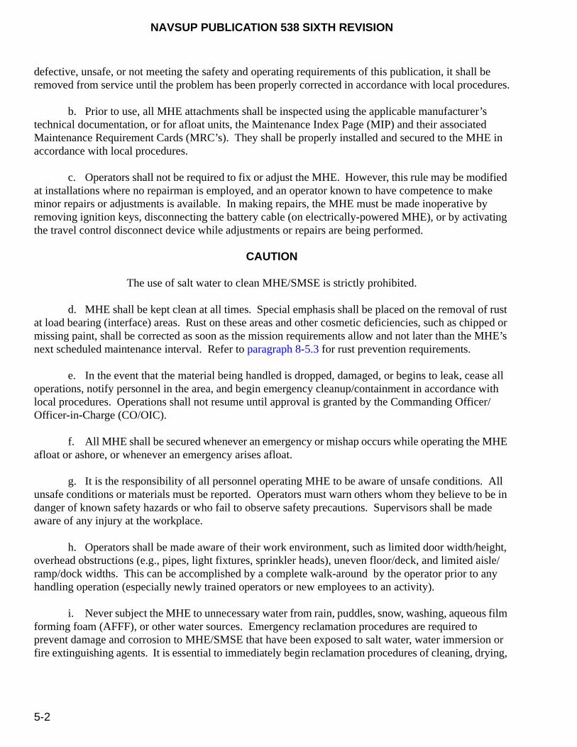
NAVSUP PUBLICATION 538 SIXTH REVISION
5-2
defective, unsafe, or not meeting the safety and operating requirements of this publication, it shall be removed from service until the problem has been properly corrected in accordance with local procedures.
b. Prior to use, all MHE attachments shall be inspected using the applicable manufacturer’s technical documentation, or for afloat units, the Maintenance Index Page (MIP) and their associated Maintenance Requirement Cards (MRC’s). They shall be properly installed and secured to the MHE in accordance with local procedures.
c. Operators shall not be required to fix or adjust the MHE. However, this rule may be modified at installations where no repairman is employed, and an operator known to have competence to make minor repairs or adjustments is available. In making repairs, the MHE must be made inoperative by removing ignition keys, disconnecting the battery cable (on electrically-powered MHE), or by activating the travel control disconnect device while adjustments or repairs are being performed.
CAUTION
The use of salt water to clean MHE/SMSE is strictly prohibited.
d. MHE shall be kept clean at all times. Special emphasis shall be placed on the removal of rust at load bearing (interface) areas. Rust on these areas and other cosmetic deficiencies, such as chipped or missing paint, shall be corrected as soon as the mission requirements allow and not later than the MHE’s next scheduled maintenance interval. Refer to paragraph 8-5.3 for rust prevention requirements.
e. In the event that the material being handled is dropped, damaged, or begins to leak, cease all operations, notify personnel in the area, and begin emergency cleanup/containment in accordance with local procedures. Operations shall not resume until approval is granted by the Commanding Officer/Officer-in-Charge (CO/OIC).
f. All MHE shall be secured whenever an emergency or mishap occurs while operating the MHE afloat or ashore, or whenever an emergency arises afloat.
g. It is the responsibility of all personnel operating MHE to be aware of unsafe conditions. All unsafe conditions or materials must be reported. Operators must warn others whom they believe to be in danger of known safety hazards or who fail to observe safety precautions. Supervisors shall be made aware of any injury at the workplace.
h. Operators shall be made aware of their work environment, such as limited door width/height, overhead obstructions (e.g., pipes, light fixtures, sprinkler heads), uneven floor/deck, and limited aisle/ramp/dock widths. This can be accomplished by a complete walk-around by the operator prior to any handling operation (especially newly trained operators or new employees to an activity).
i. Never subject the MHE to unnecessary water from rain, puddles, snow, washing, aqueous film forming foam (AFFF), or other water sources. Emergency reclamation procedures are required to prevent damage and corrosion to MHE/SMSE that have been exposed to salt water, water immersion or fire extinguishing agents. It is essential to immediately begin reclamation procedures of cleaning, drying,
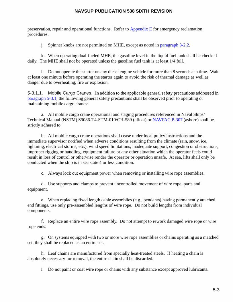
NAVSUP PUBLICATION 538 SIXTH REVISION
5-3
preservation, repair and operational functions. Refer to Appendix E for emergency reclamation procedures.
j. Spinner knobs are not permitted on MHE, except as noted in paragraph 3-2.2.
k. When operating dual-fueled MHE, the gasoline level in the liquid fuel tank shall be checked daily. The MHE shall not be operated unless the gasoline fuel tank is at least 1/4 full.
l. Do not operate the starter on any diesel engine vehicle for more than 8 seconds at a time. Wait at least one minute before operating the starter again to avoid the risk of thermal damage as well as danger due to overheating, fire or explosion.
5-3.1.1. Mobile Cargo Cranes. In addition to the applicable general safety precautions addressed in paragraph 5-3.1, the following general safety precautions shall be observed prior to operating or maintaining mobile cargo cranes:
a. All mobile cargo crane operational and staging procedures referenced in Naval Ships’ Technical Manual (NSTM) S9086-T4-STM-010/CH-589 (afloat) or NAVFAC P-307 (ashore) shall be strictly adhered to.
b. All mobile cargo crane operations shall cease under local policy instructions and the immediate supervisor notified when adverse conditions resulting from the climate (rain, snow, ice, lightning, electrical storms, etc.), wind speed limitations, inadequate support, congestion or obstructions, improper rigging or handling, equipment failure or any other situation which the operator feels could result in loss of control or otherwise render the operator or operation unsafe. At sea, lifts shall only be conducted when the ship is in sea state 4 or less condition.
c. Always lock out equipment power when removing or installing wire rope assemblies.
d. Use supports and clamps to prevent uncontrolled movement of wire rope, parts and equipment.
e. When replacing fixed length cable assemblies (e.g., pendants) having permanently attached end fittings, use only pre-assembled lengths of wire rope. Do not build lengths from individual components.
f. Replace an entire wire rope assembly. Do not attempt to rework damaged wire rope or wire rope ends.
g. On systems equipped with two or more wire rope assemblies or chains operating as a matched set, they shall be replaced as an entire set.
h. Leaf chains are manufactured from specially heat-treated steels. If heating a chain is absolutely necessary for removal, the entire chain shall be discarded.
i. Do not paint or coat wire rope or chains with any substance except approved lubricants.

NAVSUP PUBLICATION 538 SIXTH REVISION
5-4
5-3.2. PERSONNEL SAFETY. The following personnel safety precautions shall be observed prior to operating or maintaining MHE:
a. During handling operations, MHE operators shall wear all necessary personal protective equipment (PPE), such as non-metallic safety helmets, safety shoes, eye and ear protection, etc., as specified by local instructions.
b. Personnel shall not stand on or pass under the elevated portion of any MHE, whether the MHE is loaded or empty.
c. Operators shall make sure that there is sufficient headroom to operate the MHE under beams, lights, pipes, sprinkler systems and all overhead installations.
d. Operators shall keep well inside the operating compartment, making sure that feet and arms are inside the running lines of the MHE. Do not put arms or legs between the uprights of a mast.
e. Operators who have completed their prior to use daily safety inspections shall ensure that their hands are not wet or greasy prior to operating MHE.
f. Stunt driving and horseplay are prohibited. Do not spin wheels or race an engine. Never permit riders on MHE or load.
g. If the MHE is equipped with an operator restraint system (e.g., seat belt), it may not be removed, it shall be maintained, and it shall be worn for all operations with the exception of shipboard and pierside operations, which shall be at the discretion of the CO/OIC following an operational assessment.
h. Never leave the driver's seat while the MHE is in motion or when the forks are elevated above the ground/deck.
5-3.2.1. Mobile Cargo Cranes. In addition to the applicable personnel safety precautions addressed in paragraph 5-3.2, the following safety precautions shall be observed prior to operating or maintaining mobile cargo cranes:
a. Always lock out the equipment power when removing or installing wire rope assemblies.
b. To determine the required crew at each crane location, refer to NSTM S9086-T4-STM-010/CH-589 (afloat) or NAVFAC P-307 (ashore). Operation of the crane is prohibited without the presence of a qualified signalman. No load shall be moved without an approved signal from the signalman, except in the event that the crane operator detects an unsafe condition or receives an emergency stop signal from any source.
c. No loads shall be lowered, lifted or suspended directly above the tagline handlers or any other personnel. Personnel are prohibited from riding the hoist block, hook, load, or ascend or descend the crane when it is rotating.
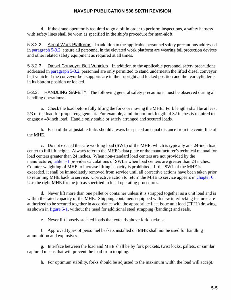
NAVSUP PUBLICATION 538 SIXTH REVISION
5-5
d. If the crane operator is required to go aloft in order to perform inspections, a safety harness with safety lines shall be worn as specified in the ship’s procedure for man-aloft.
5-3.2.2. Aerial Work Platforms. In addition to the applicable personnel safety precautions addressed in paragraph 5-3.2, ensure all personnel in the elevated work platform are wearing fall protection devices and other related safety equipment as required at all times.
5-3.2.3. Diesel Conveyor Belt Vehicles. In addition to the applicable personnel safety precautions addressed in paragraph 5-3.2, personnel are only permitted to stand underneath the lifted diesel conveyor belt vehicle if the conveyor belt supports are in their upright and locked position and the rear cylinder is in its bottom position or locked.
5-3.3. HANDLING SAFETY. The following general safety precautions must be observed during all handling operations:
a. Check the load before fully lifting the forks or moving the MHE. Fork lengths shall be at least 2/3 of the load for proper engagement. For example, a minimum fork length of 32 inches is required to engage a 48-inch load. Handle only stable or safely arranged and secured loads.
b. Each of the adjustable forks should always be spaced an equal distance from the centerline of the MHE.
c. Do not exceed the safe working load (SWL) of the MHE, which is typically at a 24-inch load center to full lift height. Always refer to the MHE’s data plate or the manufacturer’s technical manual for load centers greater than 24 inches. When non-standard load centers are not provided by the manufacturer, table 5-1 provides calculations of SWL’s when load centers are greater than 24 inches. Counter-weighting of MHE to increase lifting capacity is prohibited. If the SWL of the MHE is exceeded, it shall be immediately removed from service until all corrective actions have been taken prior to returning MHE back to service. Corrective action to return the MHE to service appears in chapter 6. Use the right MHE for the job as specified in local operating procedures.
d. Never lift more than one pallet or container unless it is strapped together as a unit load and is within the rated capacity of the MHE. Shipping containers equipped with new interlocking features are authorized to be secured together in accordance with the appropriate fleet issue unit load (FIUL) drawing, as shown in figure 5-1, without the need for additional steel strapping (banding) and seals.
e. Never lift loosely stacked loads that extends above fork backrest.
f. Approved types of personnel baskets installed on MHE shall not be used for handling ammunition and explosives.
g. Interface between the load and MHE shall be by fork pockets, twist locks, pallets, or similar captured means that will prevent the load from toppling.
h. For optimum stability, forks should be adjusted to the maximum width the load will accept.
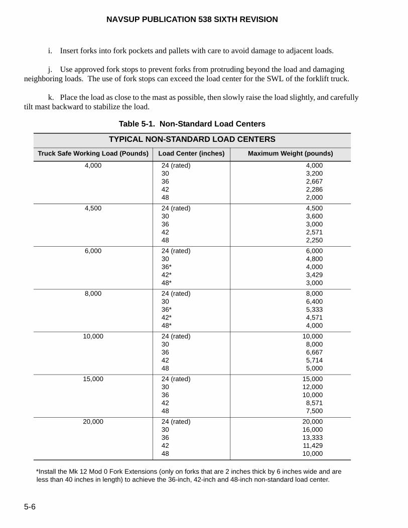
NAVSUP PUBLICATION 538 SIXTH REVISION
5-6
i. Insert forks into fork pockets and pallets with care to avoid damage to adjacent loads.
j. Use approved fork stops to prevent forks from protruding beyond the load and damaging neighboring loads. The use of fork stops can exceed the load center for the SWL of the forklift truck.
k. Place the load as close to the mast as possible, then slowly raise the load slightly, and carefully tilt mast backward to stabilize the load.
*Install the Mk 12 Mod 0 Fork Extensions (only on forks that are 2 inches thick by 6 inches wide and are less than 40 inches in length) to achieve the 36-inch, 42-inch and 48-inch non-standard load center.
Table 5-1. Non-Standard Load Centers
TYPICAL NON-STANDARD LOAD CENTERS
Truck Safe Working Load (Pounds) Load Center (inches) Maximum Weight (pounds)
4,000 24 (rated)30364248
4,0003,2002,6672,2862,000
4,500 24 (rated)30364248
4,5003,6003,0002,5712,250
6,000 24 (rated)3036*42*48*
6,0004,8004,0003,4293,000
8,000 24 (rated)3036*42*48*
8,0006,4005,3334,5714,000
10,000 24 (rated)30364248
10,0008,0006,6675,7145,000
15,000 24 (rated)30364248
15,00012,00010,0008,5717,500
20,000 24 (rated)30364248
20,00016,00013,33311,42910,000

NAVSUP PUBLICATION 538 SIXTH REVISION
5-7
FIGURE 5-1. Close-Up of Container Interlocking Feature
l. Extreme care shall be used when tilting the load forward or backward, particularly when high tiering. Tilting forward with forks elevated shall be prohibited except to lift a load. An elevated load shall not be tilted forward except when the load is in a deposit position over a rack or stack. Level the load prior to deposit on a rack or stack. When stacking or tiering, only enough backward tilt to stabilize the load shall be used.
m. Forks can be placed partially under loads for lifting, side shifting and placement, or through the corner of a pallet, provided the following conditions are met:
(1) The deck or base surface must be smooth and without obstructions.
(2) No metal-to-metal contact is permissible between the pallet and the deck.
(3) The forks must be sufficiently beneath the pallet to prevent instability.
(4) The load must not exceed the SWL at the rated load center of the forklift truck.
(5) The load must be resting on a stable surface. Partial engagement is not permissible when loads are hanging over a ledge or partially supported by a base tier.
(6) Partial engagement must only be used to move loads 1 or 2 inches in a given direction and not as the primary method of positioning.

NAVSUP PUBLICATION 538 SIXTH REVISION
5-8
(7) Loads will not be bumped in order to be repositioned.
5-3.3.1. Mobile Cargo Cranes. In addition to the applicable handling safety precautions addressed in paragraph 5-3.3, the following general safety precautions shall be observed during all mobile cargo crane handling operations:
a. The use of removable boom extensions on mobile cargo cranes is prohibited.
b. When positioning the boom on the mobile cargo crane, the hook shall be plumbed directly over the estimated center of gravity (cg) of the load before attaching the rigging gear. Loads shall be hoisted just high enough to clear any obstructions.
c. Do not use hooks which are not safety hooks or are not moused, except when using a tripping line rigged for lowering or hoisting boats only.
d. Do not use the limit switch or stop as an operating control to limit the travel of the load block, boom or crane.
Side loading the mobile cargo crane may cause structural damage to the boom, causing it to collapse.
e. Never side load the mobile cargo crane. Examples of side loading include:
(1) Rotating or traveling the crane with the load swaying from side-to-side (figure 5-2).
FIGURE 5-2. Never Side Load the Crane
CAUTION

NAVSUP PUBLICATION 538 SIXTH REVISION
5-9
(2) Hoisting or topping a load that is at rest where the hook has not been plumbed directly under the upper block.
(3) Attempting to rotate or travel the crane with the hook attached to a load at rest (dragging the load).
5-3.3.2. Diesel Conveyor Belt Vehicles. In addition to the applicable handling safety precautions addressed in paragraph 5-3.3, the following general safety precautions shall be observed during all diesel conveyor belt vehicle handling operations:
a. No passengers may ride on or in the diesel conveyor belt vehicle nor stand within the swiveling range of the vehicle. No persons are permitted to stand on the conveyor belt when the unit does not include a guardrail.
b. Do not remain in the driver’s area on diesel conveyor belt vehicles during loading and unloading operations as packages may fall from the conveyor belt.
5-3.4. SAFETY PRECAUTIONS DURING MOVEMENTS. For vessels afloat, NAVSEA maintains ship design specifications for maximum deck and ramp loads permitted with MHE. For activities ashore, the appropriate local operating procedures shall indicate the proper MHE for the operation. Refer to NAVSEA SW023-AH-WHM-010 for additional safety precautions during movement of ammunition and explosives. Prior to any movement operation, the following safety precautions must be followed:
a. Check floors, decks, dockplates, ramps, etc. for breaks, cracks, or other indications of structural weaknesses. All portable dockplates and ramps must be properly secured to prevent any movement during MHE operations. Whenever doubts arise regarding the load capacity, securement or integrity of the operational surfaces, the MHE operator shall cease operations and report the discrepancy in accordance with local procedures.
b. Prior to any MHE operation, make sure trailers and railcars are properly chocked. Railcars on piers do not require chocking.
c. Keep one hand on the steering wheel at all times. MHE will not automatically return to straight forward or reverse travel direction. The use of hand-held cellular phones, radio communication devices, or other distractions is prohibited while MHE is in motion or the forks are elevated.
d. Observe all traffic and fire regulations, including authorized speed limits. Yield right-of-way to ambulances, fire trucks or other vehicles in emergency situations. Park or store MHE in authorized areas only.
e. Under all travel conditions, MHE shall be operated at speeds that will allow it to stop in a safe manner.
f. Keep a clear view in the direction of travel.
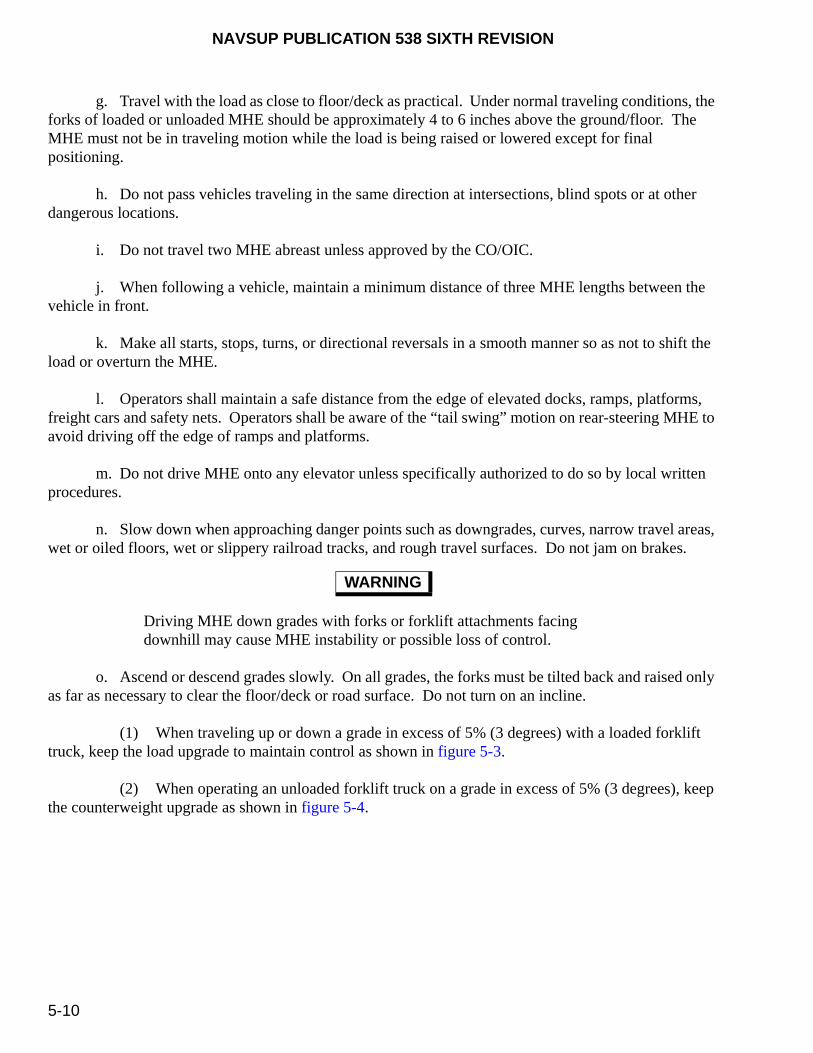
NAVSUP PUBLICATION 538 SIXTH REVISION
5-10
g. Travel with the load as close to floor/deck as practical. Under normal traveling conditions, the forks of loaded or unloaded MHE should be approximately 4 to 6 inches above the ground/floor. The MHE must not be in traveling motion while the load is being raised or lowered except for final positioning.
h. Do not pass vehicles traveling in the same direction at intersections, blind spots or at other dangerous locations.
i. Do not travel two MHE abreast unless approved by the CO/OIC.
j. When following a vehicle, maintain a minimum distance of three MHE lengths between the vehicle in front.
k. Make all starts, stops, turns, or directional reversals in a smooth manner so as not to shift the load or overturn the MHE.
l. Operators shall maintain a safe distance from the edge of elevated docks, ramps, platforms, freight cars and safety nets. Operators shall be aware of the “tail swing” motion on rear-steering MHE to avoid driving off the edge of ramps and platforms.
m. Do not drive MHE onto any elevator unless specifically authorized to do so by local written procedures.
n. Slow down when approaching danger points such as downgrades, curves, narrow travel areas, wet or oiled floors, wet or slippery railroad tracks, and rough travel surfaces. Do not jam on brakes.
Driving MHE down grades with forks or forklift attachments facing downhill may cause MHE instability or possible loss of control.
o. Ascend or descend grades slowly. On all grades, the forks must be tilted back and raised only as far as necessary to clear the floor/deck or road surface. Do not turn on an incline.
(1) When traveling up or down a grade in excess of 5% (3 degrees) with a loaded forklift truck, keep the load upgrade to maintain control as shown in figure 5-3.
(2) When operating an unloaded forklift truck on a grade in excess of 5% (3 degrees), keep the counterweight upgrade as shown in figure 5-4.
WARNING
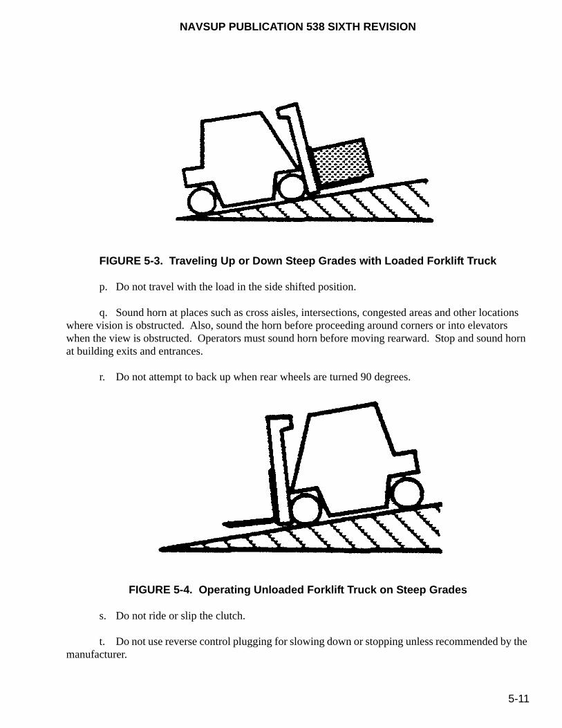
NAVSUP PUBLICATION 538 SIXTH REVISION
5-11
FIGURE 5-3. Traveling Up or Down Steep Grades with Loaded Forklift Truck
p. Do not travel with the load in the side shifted position.
q. Sound horn at places such as cross aisles, intersections, congested areas and other locations where vision is obstructed. Also, sound the horn before proceeding around corners or into elevators when the view is obstructed. Operators must sound horn before moving rearward. Stop and sound horn at building exits and entrances.
r. Do not attempt to back up when rear wheels are turned 90 degrees.
FIGURE 5-4. Operating Unloaded Forklift Truck on Steep Grades
s. Do not ride or slip the clutch.
t. Do not use reverse control plugging for slowing down or stopping unless recommended by the manufacturer.

NAVSUP PUBLICATION 538 SIXTH REVISION
5-12
u. MHE shall be completely disengaged from the load when MHE is not being operated.
v. Do not attempt to enter a building through partially opened doors. The doors shall be fully opened and secured before proceeding.
w. MHE shall not be used for opening or closing railcar door, magazine doors or to disassemble fastened dunnage.
x. Cross railroad tracks diagonally whenever possible. Do not park closer than 8 feet from the center of the railroad tracks.
y. Before driving over a dockboard or bridgeplate, be sure it is properly secured from lateral movement. Drive carefully and slowly across dockboards or bridgeplates.
z. Do not run over loose objects, bumps or potholes on the running surface.
aa. Never tow or push other MHE, vehicles or freight cars. Forklift trucks are not designed as tow vehicles. Installed towing features are intended for moving inoperative equipment. Towing is not authorized without prior NAVSUP Weapon Systems Support (NAVSUP WSS) [formerly Naval Inventory Control Point Mechanicsburg (NAVICP-M)] and the manufacturer’s approval.
bb. Never drive faster than a safety walker (spotter) can walk. Refer to paragraph 5-3.4.4 for safety walker (spotter) requirements.
5-3.4.1. Tow Tractors.. In additions to the applicable safety precautions during movements addressed in paragraph 5-3.4, the following safety precautions must be followed for two tractors prior to any movement operation.
a. When using a tow tractor, never exceed its rated towing capacity. The maximum number of trailers permitted in a trailer train shall be documented in local Standard Operating Procedures (SOP’s).
b. All tow tractor operators must comply with the following regulations:
(1) Do not weave or whip train.
(2) Allow sufficient time to get into position to make turns and allow for proper clearance of last trailer.
(3) The height of the load on the trailers shall not obstruct the rear view of the operator nor create the possibility of material falling on the operator.
(4) When a permanent passenger seat is provided, one passenger may be transported. No person shall be allowed to occupy a temporary seat or ride any part of the tractor or trailer. No person shall be permitted to ride the trailer train.
NAVSUP PUBLICATION 538 SIXTH REVISION
5-13
5-3.4.2. Mobile Cargo Cranes. In addition to the applicable safety precautions during movements addressed in paragraph 5-3.4, the following safety precautions must be followed for mobile cargo cranes prior to any movement operation:
a. When the temperature of any part of the MHE exceeds its normal operating temperature, the MHE shall be removed from service.
b. Always use supports and clamps to prevent uncontrolled movement of wire rope, parts and equipment.
c. Traveling the mobile cargo crane with a load on the hook is prohibited.
d. The crane operator will follow the direction signals of the signalman and maneuver the load into position as directed. The operator must maintain direct visual contact with the signalman at all times and shall immediately secure the operation if contact is lost.
e. Always use sufficient taglines to prevent possible load swing on cranes.
5-3.4.3. Diesel Conveyor Belt Vehicles. In addition to the applicable safety precautions during movements addressed in paragraph 5-3.4, avoid the risk of tippinig or overturning, do not attempt to drive when the diesel conveyor belt vehicle is lifted up (shunting allowed).
5-3.4.4. Safety Walker (Spotter) Requirements. The following safety walker (spotter) requirements are as follows:
(1) To assist in all MHE requirements, whenever possible.
(2) To ensure that the fork lengths are at least 2/3 of the load being lifted for proper engagement. For example, a minimum fork length of 32 inches is required to engage a 48-inch load.
(3) Whenever engaging or disengaging a load, unless a mechanical method is employed to ensure proper load location.
(4) Whenever the operator’s view is obstructed when driving in any direction, or when moving long loads, such as missile and torpedo containers.
(5) Whenever operating a straddle carrier.
(6) Must position themselves such that they have a clear view of the operator; a clear view of the load being handled and any obstructions to be avoided; and an unobstructed path to exit the area in case the load shifts, falls or other emergencies.
NAVSUP PUBLICATION 538 SIXTH REVISION
5-14
5-4. SAFETY DEVICES
Several kinds of safety devices, depending on the MHE type, are provided to ensure its safe and efficient operation.
During maintenance operations, safety devices may be removed or disabled but shall be installed or activated immediately upon completion of the scheduled tasks.
5-4.1. OVERHEAD GUARDS. 29 CFR 1910.178 requires the use of an overhead guard to protect operators from falling objects. MHE, so equipped, may have the overhead guard removed during handling operations provided the Commanding Officer/Officer-In-Charge (CO/OIC) authorizes, in writing, that the provisions of 29 CFR 1910.178 are met. A sample authorization letter is provided in figure 5-5. A copy of this authorization shall be maintained in the equipment history file. If removed to meet operational commitments, the overhead guards shall be stenciled with the USN registration number assigned to the MHE. The user is responsible for maintaining and storing them. Contact the TYCOM MHE manager to determine whether ashore storage is available.
5-4.2. LOAD BACKREST EXTENSION. 29 CFR 1910.178 requires the use of a load backrest extension whenever necessary to minimize the possibility of the load or part of it from falling rearward. MHE, so equipped, may have the load backrest removed during handling operations provided the CO/OIC authorizes, in writing, that the provisions of 29 CFR 1910.178 are met. A sample authorization letter is provided in figure 5-5. A copy of this authorization shall be maintained in the equipment history file. If removed to meet operational commitments, the load backrest extensions shall be stenciled with the USN registration number assigned to the MHE. The user is responsible for maintaining and storing them. Contact the TYCOM MHE manager to determine whether ashore storage is available.
5-4.3. SAFETY BRAKING/DISCONNECT SYSTEMS. If MHE is equipped with a deadman-type braking system, a seat braking system, or a travel disconnect device, it shall be maintained and operable.
5-4.4. STATIC DISCHARGE DEVICES. Type EE MHE shall have at least two tires and wheels constructed of electrically conductive material or some other equivalent static discharge device, such as two electrically conductive ground straps. Type EE MHE must use the same static discharge devices as originally provided by the manufacturer to maintain their accredited laboratory rating. Type EX MHE shall have at least two tires and wheels constructed of electrically conductive material. The use of electrically conductive ground straps, in lieu of conductive tires, is not permitted on type EX MHE. Conductive tires are factory marked “SC” or Static Conductive. It may also have a Underwriters’ Laboratory (UL) label. Pallet trucks marked “HS” must have static conductive tires or two electrically conductive ground straps.
5-4.5. FORK SAFETY CHAINS. All MHE containing folding-type forks shall be equipped with safety chains and locking pins to prevent the forks from accidentally extending during transport or when not in use. Safety chains and locking pins shall be properly maintained and operable.
WARNING
NAVSUP PUBLICATION 538 SIXTH REVISION
5-15
5-4.6. BATTERIES. Some explosion-proof batteries contain pressurized air or carbon dioxide which is circulated in the confines of the battery box to dilute and dissipate hydrogen gas generated by the battery. These batteries shall not be operated when they fail to comply with the manufacturer’s specifications for gas pressures and gas flows. Carbon dioxide purged batteries are being replaced by free ventilation batteries with specially designed cells and porous composition-type tops that emit gas to the outside, but prevent gas or air infiltration.
5-4.7. BACK-UP ALARM SYSTEM. On some forklift trucks, back-up alarm systems have been installed by the manufacturer. If equipped, they may not be disabled and they shall be properly maintained in accordance with manufacturer’s instructions.
5-4.8. STROBE LAMPS. If equipped, strobe lamps may not be disabled and they shall be properly maintained in accordance with manufacturer’s instructions.
5-4.9. LIMIT SAFETY SWITCHES. Limit safety switches have been installed by the manufacturer on mobile cargo cranes to limit the movement of the boom and the hoist. These switches may not be disabled and they shall be properly maintained in accordance with the manufacturer’s instructions.
5-4.10. EMERGENCY STOP SWITCHES. The aerial work platforms and the diesel conveyor belt vehicle have been equipped by the manufacturer with emergency stop switches located at the upper and lower operating positions to completely disable the equipment. These switches may not be disabled and they shall be properly maintained in accordance with the manufacturer’s instructions.
5-4.11. SAFETY GUARDRAILS. ANSI/SIA A92.5 and ANSI /SIA A92.6 require the use of safety guardrails on any boom-support aerial work platform or any self-propelled aerial work platform, respectively, for personnel safety protection. For this reason, the manufacturer has equipped safety guardrails on the aerial work platforms. They may be removed in support of maintenance operations, but must be properly installed on the same aerial work platform upon completion of all maintenance tasks.
5-4.12. APPROVED DEVICES. Only special protective devices, such as cabs, windshields, canopies, etc., which have been approved by Naval Surface Warfare Center (NAVSURFWARCEN), Indian Head Division Detachment Picatinny, Naval Packaging, Handling, Storage, and Transportation (PHST) Center (Code G1) shall be used with the MHE. Unauthorized attachments shall be removed from the MHE immediately.
5-5. SAFETY DURING FUELING
The following safety precautions apply during the fueling of MHE:
5-5.1. LOCATION. The following areas are authorized for fueling:
5-5.1.1. Afloat. MHE shall be fueled in CO/OIC designated areas only and in accordance with local procedures.
5-5.1.2. Ashore. MHE shall be fueled in accordance with NAVSEA OP 5 requirements for gas-powered vehicles.

NAVSUP PUBLICATION 538 SIXTH REVISION
5-16
FIGURE 5-5. Sample of Authorization Letter
5100(Date)
From: Commanding Officer, USS ____________________ (Hull Number)To: See Distribution
Subj: REMOVAL OF FORKLIFT OVERHEAD GUARD/LOAD BACKREST EXTENSION
Ref: (a) NAVSUP PUB 538(b) 29 CFR 1910.178
1. In accordance with reference (a) and (b), forklift (USN Reg. No.__-___________) overhead guard and/or load backrest extension is authorized to be removed in order to facilitate movement throughout ship without interface to overhead obstructions.
CO SIGNATURE
Distribution:Departments (as applicable to ship)USN Reg. No. __-____________- Equipment History File
NAVSUP PUBLICATION 538 SIXTH REVISION
5-17
5-5.2. GENERAL SAFETY REGULATIONS. The followings are general regulations associated with fueling MHE:
a. Fueled containers shall not be dropped, thrown, rolled, dragged or overfilled.
b. Only trained and designated personnel shall refill or exchange fueled containers.
c. Fueling shall be accomplished from approved dispensing pumps only.
d. Emergency fueling shall be from approved safety cans only.
5-5.3. COMPRESSED NATURAL GAS (CNG) FUEL CONTAINERS. CNG-powered MHE are fueled by steel or aluminum cylinders that meet the Department of Transportation (DOT) specification requirements of 49 CFR 170 through 179. Each container is permanently marked near the end of the container containing the outlet valve by either stamping or labeling the following information:
a. “CNG Only”;
b. Standard designation (i.e., NGV2-“x”);
c. Service pressure;
d. Manufacturer’s symbol or trademark;
e. Serial number;
f. Inspector’s symbol or trademark;
g. Manufacturer’s part number;
h. Month and year of manufacturer;
i. Maximum design material temperature; and
j. “Do Not Use After _________” where “________” is the year during which the 15-year design life will expire.
Each container shall be visually inspected once every 36 months by a qualified person in accordance with the manufacturer’s established inspection criteria and using the appropriate Compressed Gas Association (CGA) pamphlets C-6 (steel), C-6.1 (aluminum - Type NGV2-1), or C-6.2 (for all other materials). Likewise, depending on the DOT specification type, cylinders must be periodically re-qualified by a qualified person in accordance with 49 CFR 173.34. Prior to use or before refilling, containers shall be inspected for the following defects: corrosion, dents, pitting, cuts, digs, gouges, bulges, leaks, neck defects, and that it has not been exposed to fire. Additionally, there shall be no debris in or damage to the relief valve or any deterioration, damage or loss of flexible seals in the filling or servicing connection. Reject any container that fails any of these inspection criteria, remove it from service, and, if practical, have it repaired by qualified personnel before re-use. A container shall not be charged in excess of its maximum allowable working pressure at normal operating temperature. CNG fuel containers shall not be used beyond its service (design) life of 15 years from the date of the manufacturer’s marking.

NAVSUP PUBLICATION 538 SIXTH REVISION
5-18
5-5.4. LIQUEFIED PETROLEUM GAS (LPG) FUEL CONTAINERS. Propane-powered MHE is fueled by one of two types of containers, American National Standards Institute/International Truck Standards Developing Foundation (ANSI/ITSDF) tanks or DOT cylinders. Prior to use or before refilling, each type of container shall be inspected for the following defects: corrosion, dents, pitting, gouges, bulges and that it has not been exposed to fire. Also, they shall be examined for leaks (especially all seams and openings) and that the valves (usually by a device) and liquid level gauges are protected from physical damage. Reject any container that fails any of these inspection criteria, remove it from service, and, if practical, have it repaired by qualified personnel before re-use. A container shall not be charged in excess of its maximum allowable working pressure at normal operating temperature.
Always wear protective gloves and eye protection, as recommended by the Material Safety Data Sheet (MSDS), prior to filling LPG containers. Consult the manufacturer’s recommendations for filling procedures.
5-5.4.1. ANSI/ITSDF Tanks. ANSI/ITSDF tanks are built according to the ANSI/ITSDF Boiler and Pressure Vessel Code. All tanks share the following characteristics:
a. The tank capacity is calculated by the maximum amount of water they can hold.
b. They are constructed of steel.
c. They contain a marking or metal data plate to identify them.
d. They have a design pressure of 312.5 pounds per square inch gauge (psig)
No periodic qualification tests are required for ANSI/ITSDF tanks.
5-5.4.2. DOT Cylinders. DOT-approved cylinders are built according to DOT specifications under the provisions of 49 CFR 170 through 179. Unlike ANSI/ITSDF tanks, cylinders are rated by the maximum amount of propane that can be safely stored in the cylinder (expressed in pounds of propane). For example, a 33# propane cylinder is a cylinder that can safely store 33 pounds of propane. All cylinders are marked to identify them. The propane capacity is never marked on the cylinder. Instead, the water capacity is used to establish the cylinder capacity (42% of the water capacity in pounds). All cylinders must be periodically re-qualified by a qualified person using one of the three dates after the date of manufacture:
a. Within 12 years, when a letter does not follow the latest test date on the cylinder (e.g., 6-90S).
b. Within 7 years, when a letter “S” follows the latest test date (e.g., 6-90S).
c. Within 5 years, when a letter “E” follows the latest test date (e.g., 6-90E).
The date of requalification shall be stamped into the protective collar. Additionally, the relief valve must be replaced with a new or unused valve within 12 years of container manufacture and every 10 years thereafter.
WARNING

NAVSUP PUBLICATION 538 SIXTH REVISION
5-19
5-6. COLOR
All Navy-owned MHE shall be painted yellow in accordance with FED-STD-595, Color No. 13538 or a NAVSUP WSS approved equivalent. Existing green rough terrain forklift trucks shall be painted yellow during the next scheduled painting interval, except for the expeditionary force units, war reserve materiel (WRM) assets, constructions battalion (CB) assets, and cargo handling battalion (CHB) assets.
NOTE
All aerial work platforms or other MHE components received from the manufacturer in another color will be painted yellow during the next painting interval.
5-7. MARKINGS
Only the following markings are required for MHE, as applicable. If these markings are not present, the receiving activity shall mark the MHE accordingly. These markings may be applied by painted block lettering or self-adhesive decals in contrasting color. Figure 5-6 shows a typical example of the required markings and location for a shorebase electric forklift truck. Figure 5-7 shows a typical example of the required markings and location for a shipboard electric reach and tier forklift truck. Figure 5-8 shows a typical example of the required markings and location for a type HS afloat manual pallet truck.
a. Identification Plate/Label. A manufacturer’s identification plate or label shall be affixed to the MHE containing, as a minimum, the make, model, fork and mast type, and unit serial number.
Upon receipt from a direct vendor delivery, each MHE unit shall be subjected to an initial receipt inspection and servicing as required in paragraph 8-4 using the MHE Initial Receipt Inspection Form, figure 8-12, verifying the unit meets contractual requirements.
b. Manufacturer’s Certification. For new ordnance handling and shipboard MHE, a manufacturer’s marking containing the words, “STRUCTURALLY TESTED ‘DATE’ BY ‘MANUFACTURER OR FACILITY’,” shall be present on all units. Immediately upon receipt, the MHE shall be subjected to an initial receipt inspection and servicing as required in paragraph 8-4 using the MHE Initial Receipt Inspection Form, figure 8-12, verifying the unit meets contractual requirements. Additionally, before the equipment is first issued for use, the applicable general periodic tests for MHE, described in NAVSEA SW023-AH-WHM-010 shall be performed. If the MHE passes, the manufacturer’s certification marking shall be obliterated and an MHE Safety Certification marking, figure 5-9, shall be stenciled or labeled in a location that is visible to the operator upon mounting the MHE. Subsequently, an 18-month periodic weight test shall be conducted on the MHE as described in paragraph 5-7.c.
WARNING
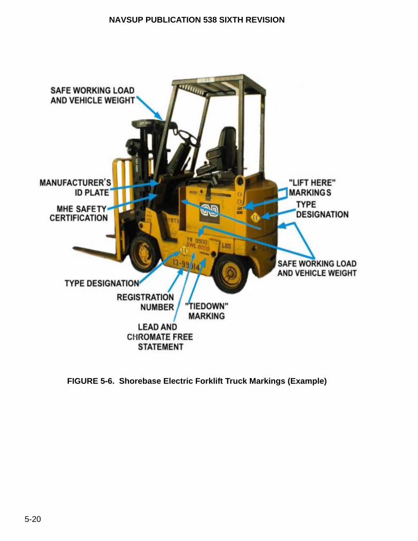
NAVSUP PUBLICATION 538 SIXTH REVISION
5-20
FIGURE 5-6. Shorebase Electric Forklift Truck Markings (Example)
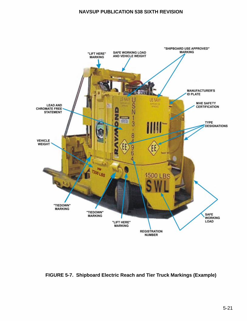
NAVSUP PUBLICATION 538 SIXTH REVISION
5-21
FIGURE 5-7. Shipboard Electric Reach and Tier Truck Markings (Example)

NAVSUP PUBLICATION 538 SIXTH REVISION
5-22
FIGURE 5-8. Afloat Manual Pallet Truck Markings (Example)
c. MHE Safety Certification. For MHE assigned to handle ammunition and explosives or are used afloat, an MHE Safety Certification Marking, figure 5-9, shall be stenciled or labeled in a location that is visible to the operator upon mounting the MHE and shall comply with the periodic testing requirements of NAVSEA SW023-AH-WHM-010.
FIGURE 5-9. MHE Safety Certification Marking
d. Accredited Laboratory Certification. Accredited laboratory certification identification, such as Underwriters’ Laboratory (UL) or Factory Mutual (FM). An example of a certification identification plate is provided in figure 5-10. If the MHE certification plate or label is missing or illegible, then a replacement certification plate or label, figure 5-11, may be present containing the unit’s serial number, the original accredited laboratory identification, and the type designation (e.g., DS, EE) annotated on it.
SAFETY CERTIFICATIONACCOMPLISHED BY:
IAW NAVSEA SW023-AH-WHM-010
EXPIRES ________________________________
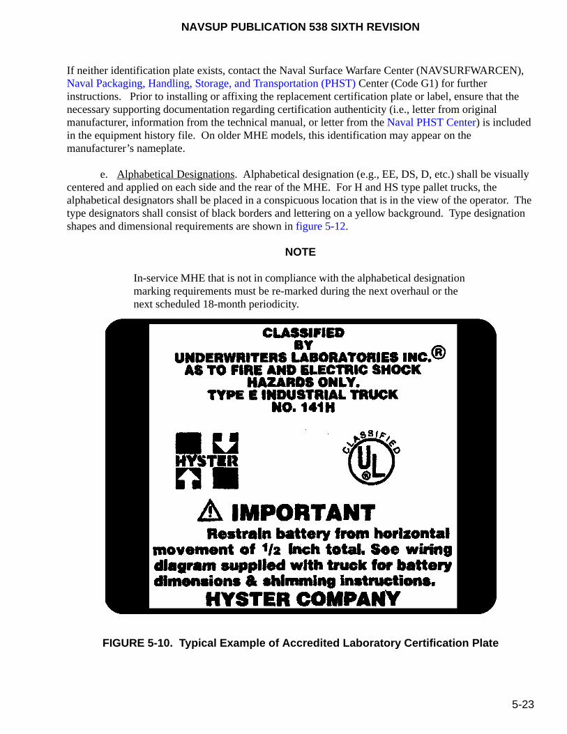
NAVSUP PUBLICATION 538 SIXTH REVISION
5-23
If neither identification plate exists, contact the Naval Surface Warfare Center (NAVSURFWARCEN), Naval Packaging, Handling, Storage, and Transportation (PHST) Center (Code G1) for further instructions. Prior to installing or affixing the replacement certification plate or label, ensure that the necessary supporting documentation regarding certification authenticity (i.e., letter from original manufacturer, information from the technical manual, or letter from the Naval PHST Center) is included in the equipment history file. On older MHE models, this identification may appear on the manufacturer’s nameplate.
e. Alphabetical Designations. Alphabetical designation (e.g., EE, DS, D, etc.) shall be visually centered and applied on each side and the rear of the MHE. For H and HS type pallet trucks, the alphabetical designators shall be placed in a conspicuous location that is in the view of the operator. The type designators shall consist of black borders and lettering on a yellow background. Type designation shapes and dimensional requirements are shown in figure 5-12.
NOTE
In-service MHE that is not in compliance with the alphabetical designation marking requirements must be re-marked during the next overhaul or the next scheduled 18-month periodicity.
FIGURE 5-10. Typical Example of Accredited Laboratory Certification Plate
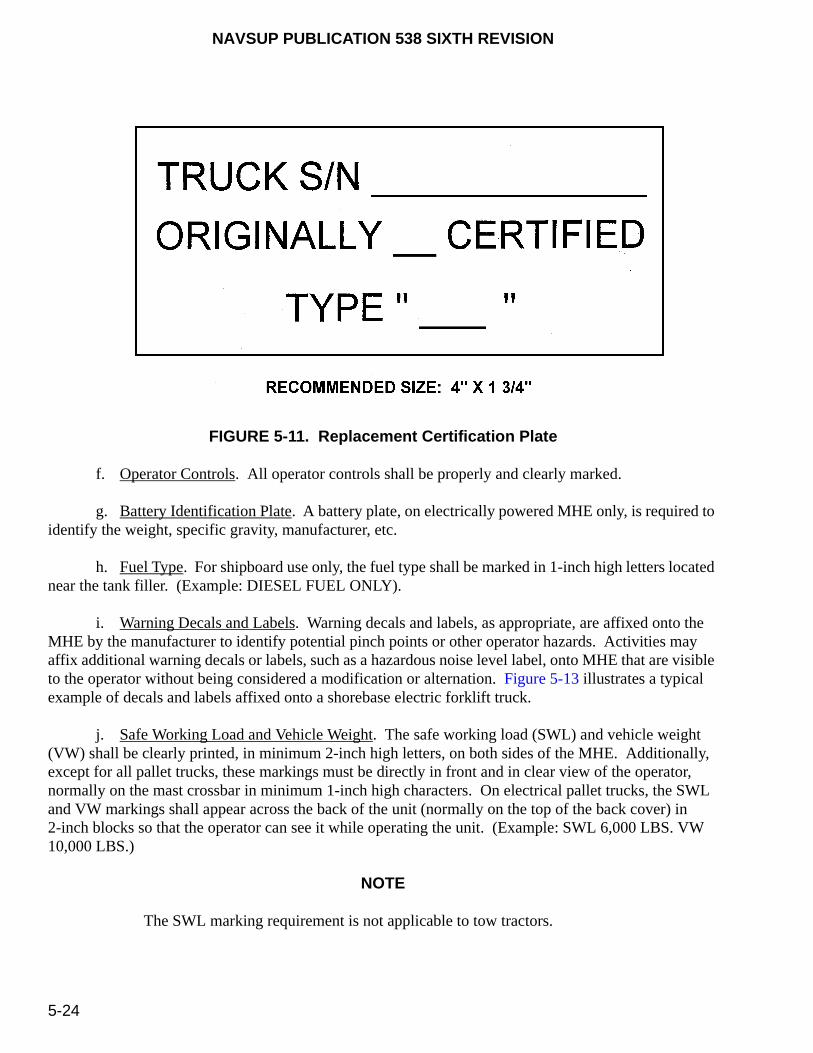
NAVSUP PUBLICATION 538 SIXTH REVISION
5-24
FIGURE 5-11. Replacement Certification Plate
f. Operator Controls. All operator controls shall be properly and clearly marked.
g. Battery Identification Plate. A battery plate, on electrically powered MHE only, is required to identify the weight, specific gravity, manufacturer, etc.
h. Fuel Type. For shipboard use only, the fuel type shall be marked in 1-inch high letters located near the tank filler. (Example: DIESEL FUEL ONLY).
i. Warning Decals and Labels. Warning decals and labels, as appropriate, are affixed onto the MHE by the manufacturer to identify potential pinch points or other operator hazards. Activities may affix additional warning decals or labels, such as a hazardous noise level label, onto MHE that are visible to the operator without being considered a modification or alternation. Figure 5-13 illustrates a typical example of decals and labels affixed onto a shorebase electric forklift truck.
j. Safe Working Load and Vehicle Weight. The safe working load (SWL) and vehicle weight (VW) shall be clearly printed, in minimum 2-inch high letters, on both sides of the MHE. Additionally, except for all pallet trucks, these markings must be directly in front and in clear view of the operator, normally on the mast crossbar in minimum 1-inch high characters. On electrical pallet trucks, the SWL and VW markings shall appear across the back of the unit (normally on the top of the back cover) in 2-inch blocks so that the operator can see it while operating the unit. (Example: SWL 6,000 LBS. VW 10,000 LBS.)
NOTE
The SWL marking requirement is not applicable to tow tractors.

NA
VS
UP
PU
BL
ICA
TIO
N 53
8 SIX
TH
RE
VIS
ION
5-2
5
FIGURE 5-12. Type Designation Shapes and Dimensions
NAVSUP PUBLICATION 538 SIXTH REVISION
5-26
k. Drawbar Pull Rating and Coupler Height. For tow tractors (figure 3-22), the maximum drawbar pull (DBP) rating (in pounds) shall be marked on both sides and the rear of the vehicle. Additionally, the coupler height shall be marked on the rear of the tractor.
l. Registration Number. The unique seven-digit unit serial number (USN), as assigned by NAVSUP WSS, shall be applied on both sides of the MHE in size to fit characters (nominal 3-inch) or, if feasible, on the mast in size to fit characters (nominal 3-inch). (Example: 13-20000). For all pallet truck, the USN Registration Number can be as small as 1-inch to fit on the sides of the unit. The serial number markings annotated on the MHE must match with the serial numbers recorded on the manufacturer’s identification plate or label as shown in paragraph 5-7.a. If discrepancies or questions arise, contact NAVSUP WSS (Code 8341) for clarification.
m. SLEP Data Plate. If MHE has undergone a SLEP Program (full or mini), a SLEP data plate in accordance with Commercial Item Description (CID) A-A-50271, with a minimum size of 2-1/2 by 4-1/2 inches, shall be affixed (using mechanical fasteners, adhesive-backed labels/plates, etc.) in the approximate protected area of the manufacturer’s data plate. Normally, this is the cowl weldment area of the MHE. The NAVSUP Fleet Logistics Center (NAVSUP FLC) [formerly Fleet and Industrial Supply Center (FISC)] Regional Manager must approve any other data plate locations. The plate shall be Composition A (non-ferrous, base alloy metal), Class 2 (aluminum) or Composition C (photo-sensitive metal) containing the following information: “SLEP, Company Name/Activity or Location, and Date (month and year).”
n. Lead Free and Chromate Free Paint. Newly procured equipment or existing MHE that has had complete paint removal shall be painted with lead free and chromate free paint. These units shall be labeled with the words, “Painted With Lead Free and Chromate Free Paint On (Month/Year) By ”(Contractor Name/Facility),” clearly printed in a protected location on both sides of the MHE. Lettering shall be a minimum of 1/4 inches in height. Units, especially older models, which do not have this marking and it cannot be verified in the procurement contract, should not be allowed to have this marking requirement unless all existing painting has been removed to the bare metal. However, if the unit does include this marking and the contract verifies it, then the unit may be repainted without removing the paint down to the bare metal and the marking applied as stated above. Touch-up or spot painting does not constitute changing the unit’s original marking condition.
o. Lifting Provisions. If applicable, the lifting provisions shall be identified with 3/4-inch high letters. (Example: LIFT HERE)
p. Tiedown Points. If applicable, all tiedown points shall be identified with 3/4-inch high letters. (Example: TIEDOWN)
q. Tire Pressure. For pneumatic tires only, the pressure markings for each tire shall be minimum 3/4-inch characters located on each side of the MHE near the applicable tire. (Example: TP 80 PSI)
r. Fuel Cap. All fuel caps shall be color coded to properly identify the required fuel type. However, JP-5 or JP-8 fuel may be substituted for diesel fuel. [Examples: DIESEL (Green, FED-STD-595, Color No. 14090) or GAS (Red, FED-STD-595, Color No. 11105)]

NAVSUP PUBLICATION 538 SIXTH REVISION
5-27
FIGURE 5-13. Warning Decals and Labels (Example) (Sheet 1 of 2)

NAVSUP PUBLICATION 538 SIXTH REVISION
5-28
FIGURE 5-13. Warning Decals and Labels (Example) (Sheet 2 of 2)
s. Shipboard Marking. Each shipboard unit shall be marked with the words, "SHIPBOARD USE APPROVED" in minimum 3/4-inch high letters identifying that the unit has passed the established criteria for shipboard use and that it can be transferred from one ship to another. However, for each unit uniquely designed or having reduced capabilities designated for a specific ship (hull), it shall be marked with the words, "SHIPBOARD USE APPROVED FOR (SHIP CLASS)". If the original marking applied by the manufacturer is missing, contact NAVSUP WSS, who maintains a record of all types/models of MHE for shipboard use. The original testing subjected on the MHE determines how the unit should be marked.
t. Striping. Type EX MHE shall have a 6-inch wide blue diagonal stripe painted at 45 degree angles along both sides and on the rear, as shown in figure 5-14. This stripe shall be in accordance with FED-STD-595, Color No. 15092, or a NAVSUP WSS approved equivalent.
u. Hydraulic Controls and Instruments. All hydraulic controls and instruments shall be clearly marked and visible when in the operator’s position. All markings shall be in accordance with the original manufacturer’s specifications. Emblems shall be applied away from edges to prevent their removal.
INDEX NUMBER
DESCRIPTIONINDEX
NUMBERDESCRIPTION
1 Label-Mast Warning 16 Mast Warning Label
2 Label-Operator Warning 17 Label, Warranty
3 Warning-OHG Impact 18 Chart Lubrication
4 Label-Operator 19 Label-Patents & Trademarks
5 Label-Parkbrake 20 Rivet
6 Battery Plate 21 Original Certification (e.g. UL, FM)
7 Label, Hood Latch 22 Shipping Data Plate E60XM 36V 102"
8 Label-Pinch Point 23 Plate-Ident E40XM-MIL 102" Mast 36
9 Model Label-Inch 40 23 Plate-Ident E60XL-MIL 102" Mast 36
10 Model Label-Inch 60 24 Nameplate Cover
11 Label, Hyster 25 Nameplate Label
12 NFPA Safety Designation 26 Nameplate Tag
13 Label, Prop Rod 27 Auxiliary Function Label
14 Label-No Riders 28 Hoist-Tilt Label
15 Label, Park Brake Release

NAVSUP PUBLICATION 538 SIXTH REVISION
5-29
v. Platform Reach and Height. According to ANSI/SIA A92.5, aerial work platforms must have the maximum reach and height markings in a clearly visible, accessible area and in a durable manner.
w. Load, Voltage and Insulation Tests. Each aerial work platform must contain the annual certification and date of the load test, the voltage and date of insulation test, and whether the unit is insulated or non-insulated. This information shall be permanently affixed, clearly understandable and readily visible to the operator.
FIGURE 5-14. Type EX (Blue Stripe)
x. Lubrication/Fluid Tag. Each aerial work platform shall be equipped with a lubricant/fluid list installed in a visible location to indicate which lubricant/fluid has been used in each component or system. The lubricants/fluids shall be listed by their commercial designation and their military equivalent, if applicable.
y. Cold Start Instructions. Aerial work platforms shall be equipped with a cold start instruction plate. It shall instruct the operator as to the steps required to use the vehicles’s cold start system.
z. No Riders Permitted. A safety warning, "NO RIDERS", shall be painted on the rear of the mast in 2-inch high letters.
aa. Brake Linings. All MHE shall have the words, "NON-ASBESTOS BRAKE LININGS" and "REPLACEMENT BRAKE LININGS TO BE NON-ASBESTOS" painted on one side in 1-inch high letters.
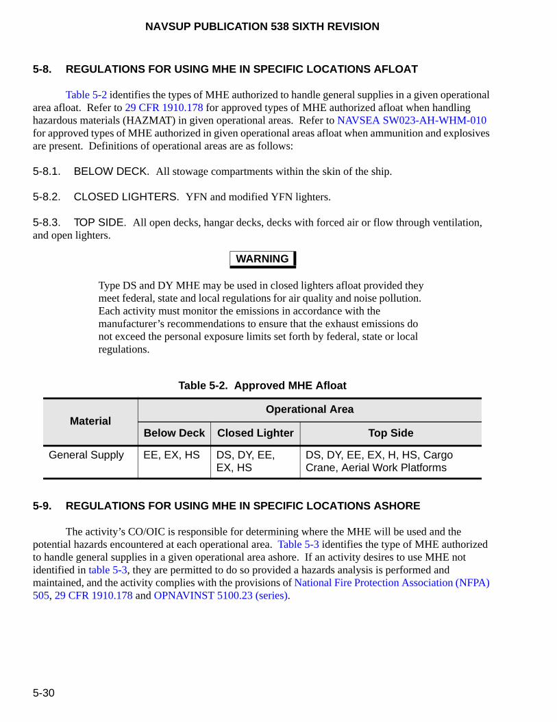
NAVSUP PUBLICATION 538 SIXTH REVISION
5-30
5-8. REGULATIONS FOR USING MHE IN SPECIFIC LOCATIONS AFLOAT
Table 5-2 identifies the types of MHE authorized to handle general supplies in a given operational area afloat. Refer to 29 CFR 1910.178 for approved types of MHE authorized afloat when handling hazardous materials (HAZMAT) in given operational areas. Refer to NAVSEA SW023-AH-WHM-010 for approved types of MHE authorized in given operational areas afloat when ammunition and explosives are present. Definitions of operational areas are as follows:
5-8.1. BELOW DECK. All stowage compartments within the skin of the ship.
5-8.2. CLOSED LIGHTERS. YFN and modified YFN lighters.
5-8.3. TOP SIDE. All open decks, hangar decks, decks with forced air or flow through ventilation, and open lighters.
Type DS and DY MHE may be used in closed lighters afloat provided they meet federal, state and local regulations for air quality and noise pollution. Each activity must monitor the emissions in accordance with the manufacturer’s recommendations to ensure that the exhaust emissions do not exceed the personal exposure limits set forth by federal, state or local regulations.
5-9. REGULATIONS FOR USING MHE IN SPECIFIC LOCATIONS ASHORE
The activity’s CO/OIC is responsible for determining where the MHE will be used and the potential hazards encountered at each operational area. Table 5-3 identifies the type of MHE authorized to handle general supplies in a given operational area ashore. If an activity desires to use MHE not identified in table 5-3, they are permitted to do so provided a hazards analysis is performed and maintained, and the activity complies with the provisions of National Fire Protection Association (NFPA) 505, 29 CFR 1910.178 and OPNAVINST 5100.23 (series).
WARNING
Table 5-2. Approved MHE Afloat
MaterialOperational Area
Below Deck Closed Lighter Top Side
General Supply EE, EX, HS DS, DY, EE, EX, HS
DS, DY, EE, EX, H, HS, Cargo Crane, Aerial Work Platforms

NAVSUP PUBLICATION 538 SIXTH REVISION
5-31
The use of powered MHE is forbidden in areas where dust vapors are known to, or can reasonably be expected to, reach explosive limits during routine operations (i.e., mixing, bulk weighing, screening, etc.).
Certain types of MHE, as identified in paragraph 3-2, require the installation of gas/vapor detection systems. For MHE not listed in table 5-3, refer to 29 CFR 1910.178. Dual-fueled forklift trucks, such as G/CN, GS/CNS, etc., shall only be used in areas authorized by t he most restrictive designation.
Refer to 29 CFR 1910.178 for approved types of MHE authorized ashore when handling hazardous materials in given operational areas. Refer to NAVSEA SW023-AH-WHM-010 for approved types of MHE authorized in given operational areas ashore when ammunition and explosives are present. Definitions of operational areas are as follows:
5-9.1. CLOSED. Buildings, structures, internal rooms and bays, etc., that have restricted ventilation that could allow the formation of a hazardous environment.
5-9.2. PARTIAL. Buildings, structures, internal rooms and bays, railcars, motor vehicles, loading ramps, platforms, etc., that have relatively unrestricted ventilation but could allow the formation of a hazardous environment.
5-9.3. OPEN. Piers, wharves, areas or structures that may have a roof but has no walls that would not restrict ventilation nor allow the formation of a hazardous environment.
MHE powered by internal combustion engines may be used in partial operational areas ashore provided they meet federal, state and local regulations for air quality and noise pollution. Each activity must monitor the emissions in accordance with the manufacturer’s recommendations to ensure that the exhaust emissions do not exceed the personal exposure limits set forth by federal, state or local regulations.
WARNING
WARNING
Table 5-3. Approved MHE Ashore
MaterialOperational Area
Closed Partial Open
General Supply E, EE, EX, GENERAL SUPPLY, ORDNANCE
CN, CNS, D, DS, DY, E, EE, EX, G, G/CN, G/LP, GS, GS/CNS, GS/LPS, GENERAL SUPPLY, ORDNANCE, LP, LPS
CN, CNS, D, DS, DY, E, EE, EX, G, G/CN, G/LP, GS, GS/CNS, GS/LPS, GENERAL SUPPLY, ORDNANCE, LP, LPS, Aerial Work Platforms, Diesel Conveyor Belt Vehicle
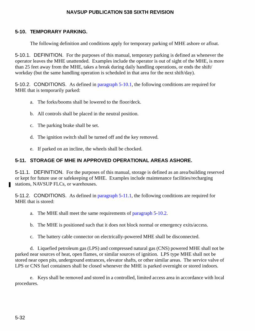
NAVSUP PUBLICATION 538 SIXTH REVISION
5-32
5-10. TEMPORARY PARKING.
The following definition and conditions apply for temporary parking of MHE ashore or afloat.
5-10.1. DEFINITION. For the purposes of this manual, temporary parking is defined as whenever the operator leaves the MHE unattended. Examples include the operator is out of sight of the MHE, is more than 25 feet away from the MHE, takes a break during daily handling operations, or ends the shift/workday (but the same handling operation is scheduled in that area for the next shift/day).
5-10.2. CONDITIONS. As defined in paragraph 5-10.1, the following conditions are required for MHE that is temporarily parked:
a. The forks/booms shall be lowered to the floor/deck.
b. All controls shall be placed in the neutral position.
c. The parking brake shall be set.
d. The ignition switch shall be turned off and the key removed.
e. If parked on an incline, the wheels shall be chocked.
5-11. STORAGE OF MHE IN APPROVED OPERATIONAL AREAS ASHORE.
5-11.1. DEFINITION. For the purposes of this manual, storage is defined as an area/building reserved or kept for future use or safekeeping of MHE. Examples include maintenance facilities/recharging stations, NAVSUP FLCs, or warehouses.
5-11.2. CONDITIONS. As defined in paragraph 5-11.1, the following conditions are required for MHE that is stored:
a. The MHE shall meet the same requirements of paragraph 5-10.2.
b. The MHE is positioned such that it does not block normal or emergency exits/access.
c. The battery cable connector on electrically-powered MHE shall be disconnected.
d. Liquefied petroleum gas (LPS) and compressed natural gas (CNS) powered MHE shall not be parked near sources of heat, open flames, or similar sources of ignition. LPS type MHE shall not be stored near open pits, underground entrances, elevator shafts, or other similar areas. The service valve of LPS or CNS fuel containers shall be closed whenever the MHE is parked overnight or stored indoors.
e. Keys shall be removed and stored in a controlled, limited access area in accordance with local procedures.
NAVSUP PUBLICATION 538 SIXTH REVISION
5-33/(5-34 Blank)
f. Refer to NAVSEA SW023-AH-WHM-010 for additional MHE storage requirements when ammunition and explosives are present.
5-12. SHIPBOARD STOWAGE OF MHE.
MHE shall be stowed aboard ship in authorized areas designated by the CO/OIC under the following conditions:
a. MHE shall meet the requirements of paragraph 5-10.2.
b. MHE shall be stowed in the fore and aft directions, whenever possible.
c. The battery must be disconnected on electrically-powered MHE.
d. Keys shall be removed and stored in a controlled, limited access area in accordance with local operating procedures.
e. A minimum of four tiedowns (e.g., wire rope, chain, universal deck-tiedown, etc.) shall be used to secure each MHE. Nylon webbing tiedown assemblies or other nylon-type tiedowns shall not be used to secure MHE. Tiedowns shall be crisscrossed such that the front left tiedown is secured to the deck near the rear left side of the MHE, and the rear left tiedown is secured to the deck near the front left side of the MHE. This process is the same for the right side tiedowns. Stanchion deck tracks are not authorized to tiedown MHE.

This page left intentionally blank

NAVSUP PUBLICATION 538 SIXTH REVISION
6-1
CHAPTER 6
EQUIPMENT MANAGEMENT AND CONTROL SYSTEM (EMACS)
6-1. GENERAL
This chapter describes the Equipment Management and Control System (EMACS), which serves as part of the Navy’s Materials Handling Equipment (MHE) preventive maintenance program. This program is designed to provide and maintain a record of services performed on MHE and to indicate the specific areas that require servicing. Establishment of this program will eliminate over-servicing that is common when maintenance history is not considered.
6-2. BENEFITS AND FUNCTIONS
The definite maintenance pattern developed from the use of EMACS will provide improved control of maintenance procedures. A typical example of a completed EMACS work order is provided in figure 6-1. The observance of features peculiar to the equipment shall be noted on the EMACS work order of reference in subsequent preventive maintenance inspections. EMACS allows users to perform MHE management on-line. Some of the key benefits for using EMACS are the elimination of hard copy quarterly reports, real time on-line access to inventory and maintenance scheduling, paperwork reduction, and adhoc reporting. The following are a few of the key functions commonly performed while using EMACS:
a. Equipment identification.
b. Maintenance tracking.
c. Quarterly reporting.
d. Utilization and availability.
e. Multi-level report capability.
6-3. HARDWARE REQUIREMENTS
All holders of Navy MHE have the capability to manage their inventory and preventive maintenance program using EMACS provided holders possess the following:
a. A 486 series personal computer (PC) or better.
b. Internet access (Internet Explorer 5.5 or better).
c. Windows 98 or better.
d. Minimum of 100 megabytes (MB) of Random Access Memory (RAM).
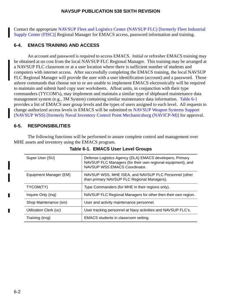
NAVSUP PUBLICATION 538 SIXTH REVISION
6-2
Contact the appropriate NAVSUP Fleet and Logistics Center (NAVSUP FLC) [formerly Fleet Industrial Supply Center (FISC)] Regional Manager for EMACS access, password information and training.
6-4. EMACS TRAINING AND ACCESS
An account and password is required to access EMACS. Initial or refresher EMACS training may be obtained at no cost from the local NAVSUP FLC Regional Manager. This training may be arranged at a NAVSUP FLC classroom or at a user location where there is sufficient number of students and computers with internet access. After successfully completing the EMACS training, the local NAVSUP FLC Regional Manager will provide the user with a user identification (account) and a password. Those ashore commands that choose not to or are unable to implement EMACS electronically will be required to maintain and submit hard copy user worksheets. Afloat units, in conjunction with their type commanders (TYCOM’s), may implement and maintain a similar type of shipboard maintenance data management system (e.g., 3M System) containing similar maintenance data information. Table 6-1 provides a list of EMACS user group levels and the types of users assigned to each level. All requests to change authorized access levels in EMACS will be submitted to NAVSUP Weapon Systems Support (NAVSUP WSS) [formerly Naval Inventory Control Point Mechanicsburg (NAVICP-M)] for approval.
6-5. RESPONSIBILITIES
The following functions will be performed to assure complete control and management over MHE assets and inventory using the EMACS program.
Table 6-1. EMACS User Level Groups
Super User (SU) Defense Logistics Agency (DLA) EMACS developers, Primary NAVSUP FLC Managers (for their own regional equipment), and NAVSUP WSS EMACS Coordinator.
Equipment Manager (EM) NAVSUP WSS, MHE ISEA, and NAVSUP FLC Personnel (other than primary NAVSUP FLC Regional Managers).
TYCOM(TY) Type Commanders (for MHE in their regions only).
Inquire Only (Inq) NAVSUP FLC Regional Managers for other then their own region.
Shop Maintenance (sm) User and activity maintenance personnel.
Utilization Clerk (uc) User tracking personnel at Navy activities and NAVSUP FLC’s.
Training (trng) EMACS students in classroom setting.

NA
VS
UP
PU
BL
ICA
TIO
N 53
8 SIX
TH
RE
VIS
ION
6-3 FIGURE 6-1. Typical Example of Completed EMACS Work Order

NAVSUP PUBLICATION 538 SIXTH REVISION
6-4
6-5.1. NAVSUP WSS. As the central EMACS database manager, NAVSUP WSS will provide the overall direction and administration for Navy EMACS. In addition, NAVSUP WSS will maintain and monitor unit and activity allowance records, and review and approve initial MHE allowances and subsequent allowance change requests (ACR’s) when significant budgetary impact exists or where an agreement cannot be reached with the requesting activity. Only NAVSUP WSS is authorized to create a new USN record. For new equipment, upon receipt of DD 250 Form, figure 6-2, NAVSUP WSS will update the appropriate equipment data into the NAVSUP WSS due in dataset and site to site to a temporary shipboard or shore-based Unit Identification Code (UIC) established for each NAVSUP FLC region and will advise the appropriate regional manager of this new receipt. Within fiscal constraints, NAVSUP WSS will match activity inventories as closely as possible to authorized allowances. NAVSUP WSS will review requests for system change requests (SCR’s), identify and resolve systematic problems at the regional level, and ensure activation of new records as equipment is procured and received by Navy activities.
6-5.2. NAVSUP FLC REGIONAL MANAGERS. All NAVSUP FLC Regional Managers shall maintain a current, regional listing of all MHE users with points of contact in EMACS. They will coordinate the establishment of EMACS accounts with the server administrator, assign level of access to accounts, and provide EMACS user training to all regional users as stated in paragraph 6-4. As required, regional managers will assist NAVSUP WSS by providing information and technical data relative to their respective regions.
6-5.2.1. New Equipment. The NAVSUP FLC Regional Manager will notify NAVSUP WSS (e.g., message, phone call, DD 1342 Form, figure 2-2, or any other acceptable means of verification) that the new equipment has been physically received in the NAVSUP FLC region. If NAVSUP WSS is aware of deliveries, they will notify the NAVSUP FLC Regional Manager. Upon receipt, the regional manager will then perform a UIC transfer from the temporary UIC to the appropriate activity. Additionally, the regional manager will enter all related maintenance schedules for those units maintained by them and other data required for local regional management.
6-5.2.2. Existing Equipment. For existing equipment, the NAVSUP FLC Regional Manager will ensure utilization, maintenance and repair data is properly entered into EMACS by all user activities. If a user activity is not on-line, the NAVSUP FLC Regional Manager is responsible for entering the required quarterly report data received from each user activity. Likewise, the regional manager will resolve field level user problems and all trouble shooting inquiries, and will submit only systemic and unresolved problems to NAVSUP WSS. All EMACS SCR’s will be submitted to NAVSUP WSS.
6-5.2.3. War Reserve Materiel (WRM). The NAVSUP FLC Regional Manager will be responsible for maintaining the EMACS database for all WRM assets.
6-5.3. MHE USERS. Ashore activities that employ MHE units are required to have their personnel establish an EMACS account, and are required to manage their inventory and maintain preventive maintenance records in this program. Ashore activities that employ 10 or fewer MHE units may contact NAVSUP WSS (Code 8341) to request a waiver from this requirement. Daily entries, if appropriate, will be the most effective means to maintain current data on utilization, maintenance tasks performed, cost information, and overall MHE readiness. Ashore MHE users are required to submit quarterly reports to their respective NAVSUP FLC Regional Manager no later than the 15th of the month. For example, the

NAVSUP PUBLICATION 538 SIXTH REVISION
6-5
first quarter fiscal year report covering the months of October, November and December would be required to be submitted to the respective NAVSUP FLC Regional Manager no later than January 15. Likewise, afloat MHE users who implement a shipboard maintenance data management system must submit similar quarterly summary reports to the respective NAVSUP FLC Regional Manager as stated above. Failure to submit quarterly reports may affect future availability of MHE assets at that activity. Figure 6-3 provides a typical example of a completed quarterly report. Figure 6-4 is a sample of a pre-printed blank EMACS quarterly report to indicate the required fields to be completed by the MHE user and to be submitted to the respective NAVSUP FLC Regional Manager.
6-5.4. TYPE COMMANDERS (TYCOM’S). For the EMACS program, TYCOM’s will have access to all Unit Identification Codes (UIC’s) within their respective Fleet commands and will be responsible for the collection and submission of user data to the NAVSUP FLC Regional Manager level on a quarterly basis. If EMACS is not implemented, TYCOM’s will be responsible to ensure that afloat units maintain a maintenance data management system and that quarterly summary reports are submitted to the NAVSUP FLC Regional Manager as described in paragraph 6-5.3.
6-6. EMACS CHANGE REQUEST
Any field level user change request or systematic problems encountered with the EMACS program will be sent to the respective NAVSUP FLC Regional Manager for resolution. Any problems that cannot be resolved at the regional level will be forwarded to NAVSUP WSS for final resolution.
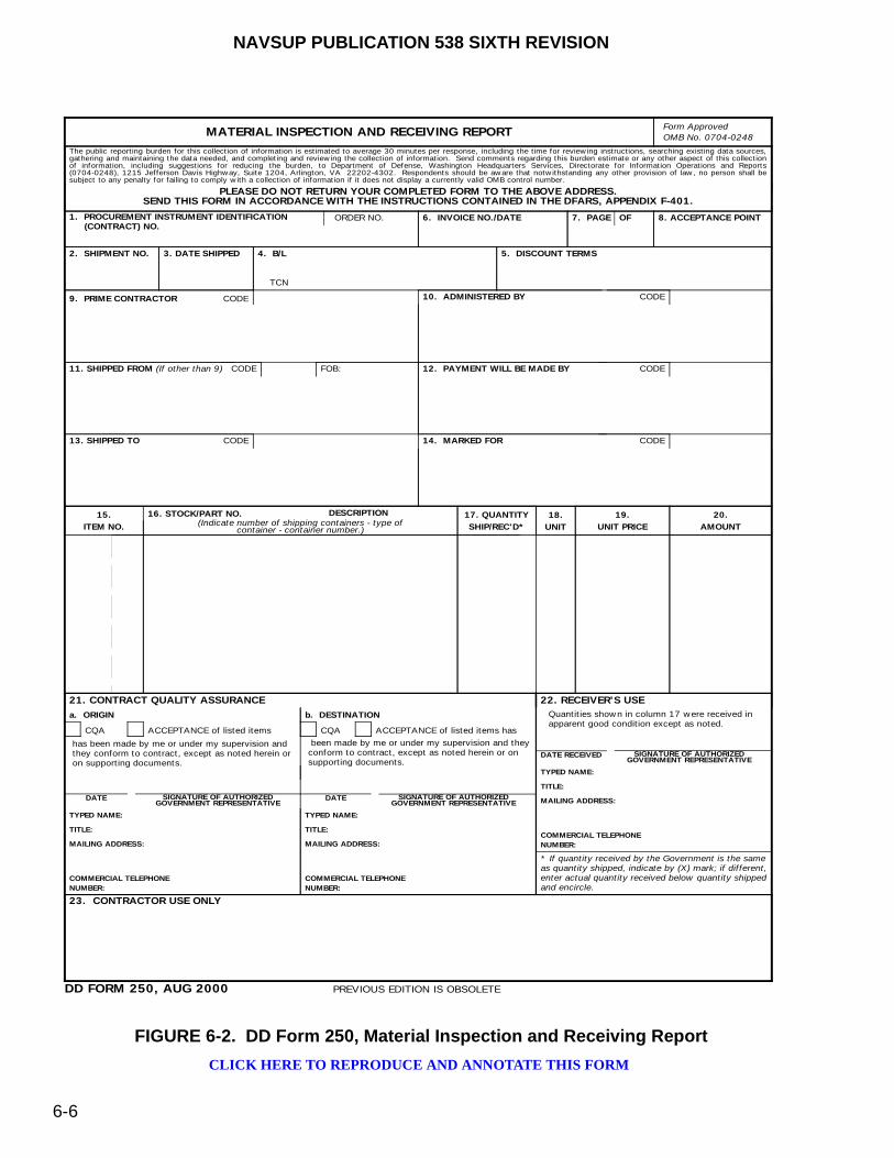
NAVSUP PUBLICATION 538 SIXTH REVISION
6-6
FIGURE 6-2. DD Form 250, Material Inspection and Receiving Report
Form Approved
OMB No. 0704-0248MATERIAL INSPECTION AND RECEIVING REPORT
PLEASE DO NOT RETURN YOUR COMPLETED FORM TO THE ABOVE ADDRESS.SEND THIS FORM IN ACCORDANCE WITH THE INSTRUCTIONS CONTAINED IN THE DFARS, APPENDIX F-401.
16. STOCK/PART NO.
21. CONTRACT QUALITY ASSURANCE 22. RECEIVER'S USE
15.
ITEM NO.
17. QUANTITY
SHIP/REC'D*
18.
UNIT
19.
UNIT PRICE
20.
AMOUNT
DESCRIPTION(Indicate number of shipping containers - type of
container - container number.)
a. ORIGIN b. DESTINATION
CQA ACCEPTANCE of listed items has
has been made by me or under my supervision andthey conform to contract, except as noted herein oron supporting documents.
been made by me or under my supervision and theyconform to contract, except as noted herein or onsupporting documents.
DATE SIGNATURE OF AUTHORIZEDGOVERNMENT REPRESENTATIVE
DD FORM 250, AUG 2000
23. CONTRACTOR USE ONLY
DATE RECEIVED
Quantities shown in column 17 were received inapparent good condition except as noted.
PREVIOUS EDITION IS OBSOLETE
CQA ACCEPTANCE of listed items
DATE
1. PROCUREMENT INSTRUMENT IDENTIFICATION (CONTRACT) NO.
6. INVOICE NO./DATE 7. PAGE OF 8. ACCEPTANCE POINT
2. SHIPMENT NO. 3. DATE SHIPPED 4. B/L
TCN
5. DISCOUNT TERMS
9. PRIME CONTRACTOR CODE 10. ADMINISTERED BY CODE
11. SHIPPED FROM (If other than 9) CODE 12. PAYMENT WILL BE MADE BY CODE
13. SHIPPED TO CODE 14. MARKED FOR CODE
FOB:
ORDER NO.
* If quantity received by the Government is the sameas quantity shipped, indicate by (X) mark; if different,enter actual quantity received below quantity shippedand encircle.
TYPED NAME:
TITLE:
MAILING ADDRESS:
COMMERCIAL TELEPHONE
NUMBER:
TYPED NAME:
TITLE:
MAILING ADDRESS:
COMMERCIAL TELEPHONE
NUMBER:
TYPED NAME:
TITLE:
MAILING ADDRESS:
COMMERCIAL TELEPHONE
NUMBER:
SIGNATURE OF AUTHORIZEDGOVERNMENT REPRESENTATIVE
SIGNATURE OF AUTHORIZEDGOVERNMENT REPRESENTATIVE
The public reporting burden for this collection of information is estimated to average 30 minutes per response, including the time for reviewing instructions, searching existing data sources,gathering and maintaining the data needed, and completing and reviewing the collection of information. Send comments regarding this burden estimate or any other aspect of this collectionof information, including suggestions for reducing the burden, to Department of Defense, Washington Headquarters Services, Directorate for Information Operations and Reports(0704-0248), 1215 Jefferson Davis Highway, Suite 1204, Arlington, VA 22202-4302. Respondents should be aware that notwithstanding any other provision of law, no person shall besubject to any penalty for failing to comply with a collection of information if it does not display a currently valid OMB control number.
CLICK HERE TO REPRODUCE AND ANNOTATE THIS FORM
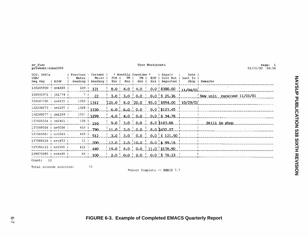
NA
VS
UP
PU
BL
ICA
TIO
N 53
8 SIX
TH
RE
VIS
ION
6-7 FIGURE 6-3. Example of Completed EMACS Quarterly Report
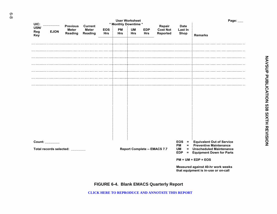
NA
VS
UP
PU
BL
ICA
TIO
N 53
8 SIX
TH
RE
VIS
ION
6-8
FIGURE 6-4. Blank EMACS Quarterly Report
User Worksheet Page: ___* Monthly Downtime *UIC: _________
USN/RegKey
EJON
PreviousMeter
Reading
CurrentMeter
ReadingEOSHrs
PMHrs
UMHrs
EDPHrs
RepairCost Not Reported
DateLast In Shop
Remarks
Count: ________
Total records selected: ________ Report Complete -- EMACS 7.7
EOS = Equivalent Out of ServicePM = Preventive MaintenanceUM = Unscheduled MaintenanceEDP = Equipment Down for Parts
PM + UM + EDP = EOS
Measured against 40-hr work weeksthat equipment is in-use or on-call
CLICK HERE TO REPRODUCE AND ANNOTATE THIS REPORT
NAVSUP PUBLICATION 538 SIXTH REVISION
7-1
CHAPTER 7
PRODUCT DEFICIENCY REPORTING
7-1. GENERAL
This chapter describes the specific types of reporting methods when deficiencies are noted on new or existing Materials Handling Equipment (MHE). For deficiencies noted on MHE that have undergone the Service Life Extension Program (SLEP), refer to Technical Memorandum No. PHST-35-00.
7-2. MANUFACTURER WARRANTIES
Manufacturer warranties protect the Government by guaranteeing the MHE against defective material, poor workmanship, and inadequate design. Warranties vary with contractor and contracting office. A typical manufacturer’s warranty extends for a period of 1 year (ashore) or 18 months (afloat) from the initial date of delivery to the U.S. Navy. However, this warranty limitation does not apply to latent defects that may later become apparent within normal service life expectancy.
7-3. MHE DEFICIENCIES
Activities ashore and afloat shall inspect all new or SLEP MHE in accordance with paragraph 8-4 prior to use to identify any deficiencies. Deficiencies will fall into one of the following categories:
a. Damage deficiencies sustained in shipment (paragraph 7-3.1).
b. Safety deficiencies (paragraph 7-3.2).
c. Warranty deficiencies (paragraph 7-3.3).
d. Contract deficiencies (paragraph 7-3.4).
e. Manufacturer’s technical manual deficiencies (paragraph 7-3.5).
7-3.1. DAMAGE DEFICIENCIES SUSTAINED IN SHIPMENT. The Supply Discrepancy Report (SDR) Program is a discrepancy reporting and resolution system. It is a tool to measure the quality of shipper performance and customer support. It is used to report shortages in shipment and transportation damages. Refer to NAVSUP Publication 723 for complete procedures and instructions related to SDR’s. The Report of Discrepancy (ROD) (Standard Form 364), figure 7-1, shall still be used to report any SDR until this form is revised. The SDR is processed through the local receiving activity who will seek appropriate resolution of the deficiency with the shipper. Shipper deficiencies and the SDR process are governed by SECNAVINST 4355.18 (series).
7-3.2. SAFETY DEFICIENCIES. MHE containing deficiencies affecting safe operation shall be immediately removed from service until corrective action has been completed. A Product Quality
NAVSUP PUBLICATION 538 SIXTH REVISION
7-2
Deficiency Report (QDR) (Standard Form 368), figure 7-2, shall be used by all activities to report unsatisfactory performance or failures attributed to faulty design or material in MHE. The completed QDR shall be forwarded to the Program Manager at NAVSUP Weapon Systems Support (NAVSUP WSS) [formerly Naval Inventory Control Point Mechanicsburg (NAVICP-M)] (Code 8341) with a copy to the Naval Surface Warfare Center (NAVWARCEN), Indian Head Division Detachment Picatinny, Naval Packaging, Handling, Storage and Transportation (PHST) Center (Code G1) for investigation and resolution. For urgent or potential safety deficiencies, a message may be generated and forwarded to NAVSUP WSS and the Naval PHST Center to expedite the engineering investigation process. NAVSUP WSS will identify and, if necessary, notify other activities affected by this safety deficiency. After initial reporting of the safety deficiencies, activities shall pursue the same action identified in the following paragraphs for warranty and contract deficiencies. In-house repairs to correct a safety deficiency shall have the manufacturer’s authorization.
7-3.2.1. Conditions for Reporting Product QDR’s. A Product QDR will be submitted when a deficiency occurs, or recurs, under any of the following circumstances:
a. Deficiency constitutes a hazard to personnel or equipment regardless of the nature or incidence of failures.
b. Deficiency involves general unsatisfactory operation or performance of equipment, including new equipment just placed in operation.
c. Deficiency is due to inadequacy in the design of certain components considered necessary for proper operation, maintenance, or handling of equipment.
d. Deficiency is due to excessive wear and deterioration for the period of time and conditions under which the item was in use or on hand.
e. Deficiency is apparently due to faulty material.
f. Deficiency is due to circumstances other than those indicated above, but is considered to be of sufficient importance to warrant reporting to a higher authority.
7-3.2.2. Preparing QDR’s. The following procedures apply to the preparation and submission of Product QDR’s, that involve the operation of MHE. This guidance is not intended to change Standard Operating Procedures (SOP’s) for all QDR’s, but is to ensure more timely and complete processing of problems involving MHE.
a. Initiation. QDR’s which are initiated by the NAVSUP Fleet Logistics Center (NAVSUP FLC)[formerly Fleet and Industrial Supply Center (FISC)] Regional Manager or other shore activities shall be forwarded directly to NAVSUP WSS (Code 8341) with a copy to the Naval PHST Center (Code G1). QDR’s initiated by units afloat shall be completed and forwarded to the appropriate TYCOM, that will determine if a Fleet-wide problem exists, but in any case, the TYCOM will immediately forward the QDR to NAVSUP WSS (Code 8341). Any defect reported as a casualty report (CASREP) should also be forwarded with the QDR to NAVSUP WSS (Code 8341).

NAVSUP PUBLICATION 538 SIXTH REVISION
7-3
b. Completing QDR’s. Instructions are provided in figure 7-2 to properly complete the Product QDR. Other equivalent forms (e.g., CASREP, email, etc.) may be used provided the same information required on the Product QDR is documented on that form. Additionally, when completing details (block 22), provide as many specific details about the failure as possible. If applicable, provide the part number of the failed component, the USN number, and the manufacturer’s serial number. If more than one MHE has the same failure, provide the USN number and serial number for each unit affected. Also, ensure that a point of contact, including an accurate phone number, is documented on the QDR. In addition to being provided as figure 7-2, blank Product QDR Forms are available through the supply system (NSN 7640-00-133-5541) and by clicking here.
c. Screening Point. Upon receipt of any QDR, NAVSUP WSS (Code 8341) will serve as the screening point, forward the QDR to the In-Service Engineering Agent (ISEA) and to the Defense Logistics Agency (DLA) contracting officer, and contact the QDR originator and other supporting Commands with the final resolution. NAVSUP WSS will actively manage all QDR’s. When closure to the QDR has been established, NAVSUP WSS will report these results.
(1) ISEA Responsibility. The ISEA will review the QDR and determine whether or not a safety hazard exists. If safety is a consideration, the ISEA shall immediately issue a message to all concerned advising of precautions to be taken and the plan of action to process the QDR. If safety is not a factor, NAVSUP WSS will issue a message advising the nature of the QDR and plans to process the QDR.
(2) DLA Responsibility. The DLA contracting officer will review the QDR and determine whether or not the equipment is under manufacturer warranty. If under warranty, the contracting officer will be requested by NAVSUP WSS to contact the manufacturer within 24 hours and establish an agreement to investigate the QDR and initiate repair or modification actions as soon as possible. NAVSUP WSS will monitor the progress of this activity to assure timeliness and accuracy in response to the QDR. If not under warranty, the contracting officer will determine if a product latent defect exists and will pursue a solution to the QDR from that perspective. If no warranty or latent defect features apply, the contracting officer is to notify NAVSUP WSS of that decision as soon as possible.
d. Status of QDR’s. Regardless of the QDR decision, NAVSUP WSS will make at least biweekly contact with the contracting officer to determine the status of the QDR review. If a warranty or latent defect applies, NAVSUP WSS will ensure the manufacturer generates a repair plan within a reasonable period of time, and will notify Fleet users as to the status of the QDR. All repairs under these circumstances are to be completed at the site of the submitting activity. If no warranty or latent defect feature can be applied, NAVSUP WSS will schedule a meeting with all activities concerned to develop a repair plan. Usually as a general rule, the user activity will be responsible for repair payment in these instances. If a Fleet-wide problem exists, NAVSUP WSS will attempt to acquire and provide funding, as available.
7-3.3. WARRANTY DEFICIENCIES. For reporting MHE deficiencies that are still under the manufacturer’s warranty, the same Product QDR process as stated in paragraph 7-3.2 applies.
7-3.4. LATENT DEFICIENCIES. For reporting MHE deficiencies that are beyond the manufacturer’s warranty, the same Product QDR process as stated in paragraph 7-3.2 applies.
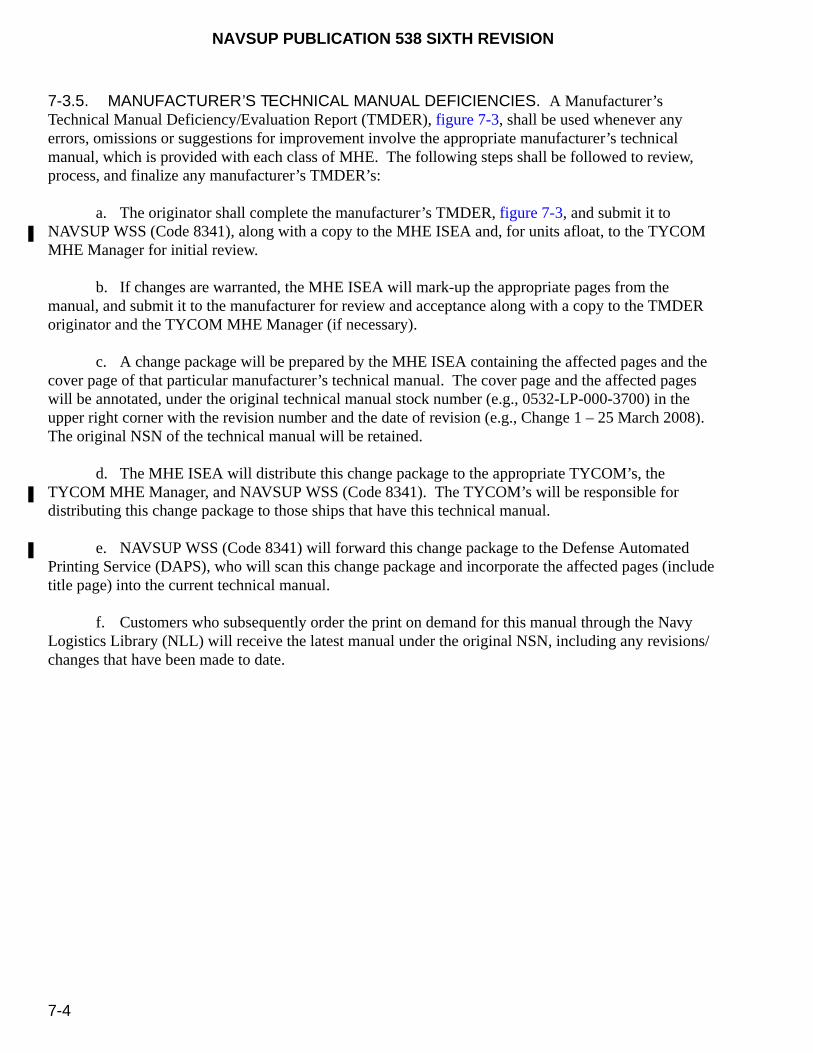
NAVSUP PUBLICATION 538 SIXTH REVISION
7-4
7-3.5. MANUFACTURER’S TECHNICAL MANUAL DEFICIENCIES. A Manufacturer’s Technical Manual Deficiency/Evaluation Report (TMDER), figure 7-3, shall be used whenever any errors, omissions or suggestions for improvement involve the appropriate manufacturer’s technical manual, which is provided with each class of MHE. The following steps shall be followed to review, process, and finalize any manufacturer’s TMDER’s:
a. The originator shall complete the manufacturer’s TMDER, figure 7-3, and submit it to NAVSUP WSS (Code 8341), along with a copy to the MHE ISEA and, for units afloat, to the TYCOM MHE Manager for initial review.
b. If changes are warranted, the MHE ISEA will mark-up the appropriate pages from the manual, and submit it to the manufacturer for review and acceptance along with a copy to the TMDER originator and the TYCOM MHE Manager (if necessary).
c. A change package will be prepared by the MHE ISEA containing the affected pages and the cover page of that particular manufacturer’s technical manual. The cover page and the affected pages will be annotated, under the original technical manual stock number (e.g., 0532-LP-000-3700) in the upper right corner with the revision number and the date of revision (e.g., Change 1 – 25 March 2008). The original NSN of the technical manual will be retained.
d. The MHE ISEA will distribute this change package to the appropriate TYCOM’s, the TYCOM MHE Manager, and NAVSUP WSS (Code 8341). The TYCOM’s will be responsible for distributing this change package to those ships that have this technical manual.
e. NAVSUP WSS (Code 8341) will forward this change package to the Defense Automated Printing Service (DAPS), who will scan this change package and incorporate the affected pages (include title page) into the current technical manual.
f. Customers who subsequently order the print on demand for this manual through the Navy Logistics Library (NLL) will receive the latest manual under the original NSN, including any revisions/changes that have been made to date.

NAVSUP PUBLICATION 538 SIXTH REVISION
7-5
FIGURE 7-1. SF 364, Report of Discrepancy (Sheet 1 of 2)
INSTRUCTIONS
DEPARTMENT OF DEFENSE: DLAR 4140.55/AR 735-11.2/NAVSUPINST 4440.127E/AFR 400-54/MCO 4430.3E, Reporting of Item and Packaging Discrepancies, and/orDLAR 4140.60/AR 12-12/NAVSUPINST 4920.9B/AFR 67-7/MCO 4140.1B, Processing Discrepancy Reports Against Foreign Military Sales Shipments.CIVILIAN AGENCIES: See FPMR handbook cited in 19(2)(a).
REPORT OF DISCREPANCY (ROD)
SHIPPING PACKAGING
1. DATE OF PREPARATION 2. REPORT NUMBER
3. TO (Name and address, include ZIP Code) 4. FROM (Name and address, include ZIP Code)
5a. SHIPPER'S NAME 5b. NUMBER AND DATE OF INVOICE 6. TRANSPORTATION DOCUMENT NUMBER(GBL., Waybill, TCN, etc.)
7a. SHIPPER'S NUMBER (PurchaseOrder/Shipment, Contract, etc.)
7b. OFFICE ADMINISTERING CONTRACT 8. REQUISITIONER'S NUMBER (Requisition,Purchase Request, etc.)
9. SHIPMENT, BILLING, AND RECEIPT DATA 10. DISCREPANCY DATA
AC-TIONCODE
11. 2NSN/PART NUMBER AND
NOMENCLATURE
(a)
UNITOF
ISSUE(b)
QUANTITYSHIPPED/BILLED
(c)
QUANTITYRECEIVED
(d)
QUAN-TITY
(a)
UNITPRICE
(b)
TOTALCOST
(c)
1CODE
(d)
12. REMARKS (Continue on separate sheet of paper if necessary)
1 DISCREPANCY CODES 2 ACTION CODESCONDITION OF MATERIAL C1 - In condition other than that indicated on release/receipt document C2 - Expired shelf life C3 - Damaged parcel post shipmentSUPPLY DOCUMENTATION D1 - Not received D2 - Illegible or mutilated D3 - Incomplete, improper or without authority (Only when receipt cannot be properly processed)MISDIRECTED MATERIAL M1 - Addressed to wrong activityOVERAGE/DUPLICATE SHIPMENTS O1 - Quantity in excess of that on receipt document O2 - Quantity in excess of that requested (Other than unit of issue pack) O3 - Quantity duplicates shipmentPACKING DISCREPANCY P1 - Improper preservation P2 - Improper packing P3 - Improper marking P4 - Improper unitization
PRODUCT QUALITY DEFICIENCIES Q1 - Deficient material (Applicable to Grant Aid and FMS shipments)SHORTAGE OF MATERIAL S1 - Quantity less than that on receipt document S2 - Quantity less than that requested (Other than unit of issue pack) S3 - Non-receipt of parcel post shipmentsITEM TECHNICAL DATA MARKINGS (i.e., Name Plates, LogBooks, Operating Handbooks, Special Instructions, etc.) T1 - Missing T2 - Illegible or mutilated T3 - Precautionary operational markings missing T4 - Inspection data missing or incomplete T5 - Serviceability operating data missing or incomplete T6 - Warranty data missingWRONG ITEM (Identify requested item as a separate copy inItem 9 above) W1 - Incorrect item received W2 - Unacceptable substituteOTHER DISCREPANCIES Z1 - See remarks
1A - Disposition instructions requested (Reply on reverse)1B - Material being retained (See remarks)1C - Supporting supply documentation requested1D - Material still required expedite shipment (Not applicable to FMS)1E - Local purchase material to be returned at supplier's expense unless disposition instructions to the contrary are received within 15 days (Reply on reverse) (Not applicable to FMS)1F - Replacement shipment requested (Not applicable to FMS)1G - Reshipment not required. Item to be re-requisitioned1H - No action required. Information only.1Z - Other action requested (See remarks)
13. FUNDING AND ACCOUNTING DATA
14a. TYPED OR PRINTED NAME, TITLE, AND PHONE NUMBER OF PREPARING OFFICIAL 14b. SIGNATURE
15. DISTRIBUTION ADDRESSEES FOR COPIES
364-103 7540-00-159-4442 (Previous edition is obsolete.) STANDARD FORM 364 (REV. 2-80) (EG)Prescribed by GSA FPMR 101-26.8
CLICK HERE TO REPRODUCE AND ANNOTATE THIS FORM
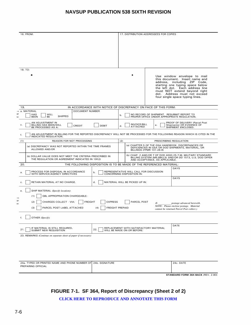
NAVSUP PUBLICATION 538 SIXTH REVISION
7-6
FIGURE 7-1. SF 364, Report of Discrepancy (Sheet 2 of 2)
16. FROM: 17. DISTRIBUTION ADDRESSEES FOR COPIES
18. TO:
Use window envelope to mailthis document. Insert name andaddress, including ZIP Code,starting one typing space belowthe left dot. Each address linemust NOT extend beyond rightdot. Address must not exceedfour single space typing lines.
19. IN ACCORDANCE WITH NOTICE OF DISCREPANCY ON FACE OF THIS FORM:
ldre
HASBEEN
a. MATERIALWILLBE SHIPPED
DOCUMENT NUMBERNO RECORD OF SHIPMENT. RESUBMIT REPORT TOPROPER OFFICE UNDER APPROPRIATE REGULATION.
b.
AN ADJUSTMENT IN BILLING HAS BEEN/WILLBE PROCESSED AS A:
c. CREDIT DEBITINVOICE/BILLATTACHEDd.
PROOF OF DELIVERY (Parcel PostShipments) OR EVIDENCE OFSHIPMENT ENCLOSED.
e.
AN ADJUSTMENT IN BILLING FOR THE REPORTED DISCREPANCY WILL NOT BE PROCESSED FOR THE FOLLOWING REASON WHICH IS CITED IN THEINDICATED REGULATION.
f.
(1) REASON FOR NOT PROCESSING
(a) DISCREPANCY WAS NOT REPORTED WITHIN THE TIME FRAMES ALLOWED AND/OR
(b) DOLLAR VALUE DOES NOT MEET THE CRITERIA PRESCRIBED IN THE REGULATION OR AGREEMENT INDICATED IN 19f(2)
(2) PRESCRIBING REGULATION
(a) CHAPTER 5 OF THE GSA HANDBOOK, DISCREPANCIES OR DEFICIENCIES IN GSA OR DOD SHIPMENTS, MATERIAL, OR BILLINGS (FPMR 101-26.8)
(b) CHAP. 2 AND/OR 7 OF DOD 4000.25-7-M, MILITARY STANDARD BILLING SYSTEM (MILSBILLS) AND/OR DD 1513, U.S. DOD OFFER AND ACCEPTANCE, AS APPLICABLE.
20. THE FOLLOWING DISPOSITION IS TO BE MADE OF THE REFERENCED MATERIAL:
PROCESS FOR DISPOSAL IN ACCORDANCEWITH SERVICE/AGENCY DIRECTIVES
a. REPRESENTATIVE WILL CALL FOR DISCUSSIONCONCERNING DISPOSITION IN:
b.
DAYS
RETAIN MATERIAL AT NO CHARGE.c. MATERIAL WILL BE PICKED UP IN:d.
DAYS
SHIP MATERIAL (Specify location):e.
GBL APPROPRIATION CHARGEABLE:(1)
CHARGES COLLECT - VIA:(2) FREIGHT EXPRESS PARCEL POST ($ __________ postage advanced herewith.NOTE: Please enclose postage. Materialcannot be returned Parcel Post collect.)PARCEL POST LABEL ATTACHED(3) (4) FREIGHT PREPAID
OTHER (Specify)f.
IF MATERIAL IS STILL REQUIRED,SUBMIT NEW REQUISITION21.
REPLACEMENT WITH SATISFACTORY MATERIAL WILL BE MADE ON OR BEFORE:22.
DATE
23. REMARKS (Continue on separate sheet of paper if necessary)
24a. TYPED OR PRINTED NAME AND PHONE NUMBER OFPREPARING OFFICIAL
24b. SIGNATURE 24c. DATE
ldre
STANDARD FORM 364 BACK (REV. 2-80)
CLICK HERE TO REPRODUCE AND ANNOTATE THIS FORM

NAVSUP PUBLICATION 538 SIXTH REVISION
7-7
FIGURE 7-2. SF 368, Product Quality Deficiency Report (Blank) (Sheet 1 of 2)
PRODUCT QUALITY DEFICIENCY REPORT (PQDR)
I II
1a. FROM (Original Office Mailing Address - include DoDAAC)
2a. TO (PQDR Screening Point)
1b. ORIGINATOR NAME, PHONE NUMBER & E-MAIL ADDRESS
2b. SCREENING POINT NAME, TELEPHONE NUMBER & E-MAIL ADDRESS
REPORT CONTROL NUMBER (RCN)
4. DATE DEFICIENCY WAS DISCOVERED
6. DEFICIENT ITEM NOMENCLATURE
8. DEFICIENT ITEM PART NUMBER
7. OPERATING TIME AT FAILURE Initial
Hours: Days:Cycles: Miles:
Rounds:
9a. MANUFACTURER'S CAGE CODE
13a. CONTRACT NUMBER
9b. MANUFACTURER / CITY / STATE
10. QUANTITYa. RECEIVED:
b. INSPECTED:
c. DEFICIENT:
d. IN STOCK:
13b. REQUISITION / DOCUMENT NUMBER 13c. PURCHASE ORDER NUMBER
11. SERIAL, LOT, OR BATCH NUMBER
SERIAL #:
LOT #:
BATCH #:
Unknown
N/A
12a. ITEM
New
Overhauled
Repaired
Unknown
12b. DATE MANUFACTURED, REPAIRED, OR OVERHAULED
Manufactured:
Repaired:
Overhauled:
a. NSN
14. GOVERNMENT FURNISHED MATERIAL
YES NO UNKNOWN
15a. ITEM UNDER WARRANTY
YES NO UNKNOWN
15b. WARRANTY EXPIRATION DATE
20. LOCATION OF DEFICIENT MATERIAL (e.g. Base, Camp, Station)
21. ACTION REQUESTED (Select only one value) REPAIR OTHER (Explain in Block 3)CREDITREPLACEMENT
19. CURRENT DISPOSITION OF DEFICIENT ITEM (the Exhibit) (Select only one value)
DISPOSED OF / DESTROYED REPAIREDHOLDING EXHIBIT OTHER (Explain in Block 3)
5. DEFICIENT ITEM NATIONAL STOCK NUMBER (NSN)
Other:
17. NEXT HIGHER ASSEMBLY
18. END ITEM
a. NSN
b. NOMENCLATURE c. TYPE/MODEL d. SERIAL NUMBER
b. NOMENCLATURE c. PART NUMBER d. SERIAL NUMBER
12c. LAST REPAIR FACILITY
DODAAC:CAGE:
REPAIR DEPOT / CITY / STATE
3. DESCRIPTION OF DEFICIENCY (Describe in detail what is wrong, circumstances prior to the difficulty, probable cause, any action taken, and recommendations. Attach copy of supporting documents. Continue on separate sheet if necessary. Ensure that the description answers the questions listed in the instructions on the back of this form.)
16. END ITEM EIC/WUC/TAMCN
DATECATEGORY
368-102 STANDARD FORM 368 (REV. 5/2011) GENERAL SERVICES ADMINISTRATION(FPMR 101 - 26.8)
CLICK HERE TO REPRODUCE AND ANNOTATE THIS FORM

NAVSUP PUBLICATION 538 SIXTH REVISION
7-8
FIGURE 7-2. SF 368, Product Quality Deficiency Report (Blank) (Sheet 2 of 2)
CATEGORY - A Category I PQDR is described as an item that could cause loss of life or catastrophic failure of a major weapon system. Category II PQDRs are all those which are not Category I. Category I justification shall be provided in Description of Deficiency, Block 3. REPORT CONTROL NUMBER (RCN) - Unique number assigned to identify the PQDR. It is comprised of the six position originating activity DODAAC, a two digit calendar year, and a unique four position serial number, e.g. M12000-10-0001. DATE - The date the SF368 is filled out. 1a. FROM (Originating Office Mailing Address) - Complete name of activity (no acronyms when sending deficiency report across component lines), activity address code (AAC) mailing address including zip code of the activity originating the report and current location of the activity. 1b. ORIGINATOR NAME, PHONE NUMBER & E-MAIL ADDRESS - Provide name, telephone number (including all available telephone numbers; FTS; Autovon, and commercial) and e-mail address of an individual who can serve as a contact for questions regarding the report and/or to request exhibits or samples. For units that are deployed, please state deployed. 2a. TO (PQDR Screening Point) - The originating point will complete the name of the screening point activity (no acronyms) activity address code (AAC) mailing address including zip code of the screening point where the report needs to be sent by the originator's activity. For those activities that do not have screening points, leave blank. 2b. SCREENING POINT NAME, TELEPHONE NUMBER AND E-MAIL ADDRESS - If available, provide the name, telephone number, and e-mail address of the screening point individual. 3. DESCRIPTION OF DEFICIENCY - A comprehensive description of the deficiency to include circumstances prior to the failure. Explain, to the best of your ability, what is wrong with the item. Explain how the item does not function with relating parts or assemblies. Include specific drawings, specifications, regulations, instructions, or contracts. If an item is dimensionally incorrect, list the actual dimensions as well as the source of the correct dimensions (tech manual/drawing or comparative measurement of the old item). As best as you can, also include the following:
• Condition of packaging when received. • Condition of part when removed from packaging. • Was defect discovered prior to or after installation? • How was deficiency discovered? • How was deficiency confirmed? • Were there any ID markings or stamps on deficient item? • Were serviceable tags attached or available when item was received? • Are pictures of the defective item available? • Describe or identify any tests or procedures used during installation and/or testing. • Identify (by RCN) any previous related (by NSN or defect) PQDRs that you know of or have
submitted. 4. DATE DEFICIENCY WAS DISCOVERED - Date when the deficiency occurred or was discovered.
5. DEFICIENT ITEM NATIONAL STOCK NUMBER (NSN) - The National Stock Number consists of the four digit Federal Supply Classification (FSC) and nine digit National Item Identification Number (NIIN). The FSC identifies the general stock classification (9999 is MISCELLANEOUS ITEM). The FSC can be found in the Indexes Cataloging Handbook H2. It can also be found on this web site, http://www.dlis.dla.mil/h2. The NSN can often be found on the attached paperwork (DD250 or 1348 form), the product packaging, and in some cases on the item itself (example on manufacturer label or nameplate). Examples: (4730-00-013-0987), (4730-000130987) COG & SMIC - Where applicable, the two character Cognizance Code (COG) and two character Special Material Identification Code (SMIC) shall be reported. The COG code identifies the Item Manager (ex: 7H, 9C). The SMIC identifies material under special programs or applications (ex: L1, X3)."
6. DEFICIENT ITEM NOMENCLATURE - The name of the deficient item at its lowest identifiable level. 7. OPERATING TIME AT FAILURE - Time item had been in operation since new, overhauled, or repaired when the deficiency was discovered citing the appropriate performance element (miles, cycles, hours etc.). Enter "Initial” if the deficiency occurred with no operation time since new, overhauled, or repaired. 8. DEFICIENT ITEM PART NUMBER - The manufacturer's part number of the deficient item. This number may be found on the item or package markings. 9a. MANUFACTURER'S CAGE CODE - A five digit Contract and Government Entity (CAGE) Code of the manufacturer (of the deficient item) as listed in the DLA Cataloging Handbook H4.1 (Name to code), Federal Supply Code for manufacturer (United States and Canada). The CAGE Code may be taken from the markings on the deficient item. NOTE: If the deficient item was repaired or overhauled, the CAGE or DODAAC of the last repair/overhaul facility shall be entered in Block 12c. 9b. MANUFACTURER / CITY / STATE - Name and address of the manufacturer which manufactured, repaired or overhauled the deficient item. For motor vehicles or components thereof, enter name of manufacturer of the vehicle or component, as appropriate. 10. QUANTITY: a. RECEIVED - Enter the total number of items or parts received. b. INSPECTED - Enter the total number of items inspected. c. DEFICIENT - Enter the quantity found deficient of those inspected.
10. QUANTITY: continued d. IN STOCK - Enter the quantity of additional material from the same manufacturer and
contract remaining in stock. 11. SERIAL / LOT / BATCH NUMBER - Enter the manufacturer's serial, lot, or batch number of the deficient items as applicable. If any of these are unknown or don't apply, check the respective boxes for Unknown or N/A. If multiple numbers are reported, provide additional numbers in Description of Deficiency, Block 3. 12a. ITEM - Check the appropriate block to indicate whether the deficient item is New, Repaired, or Overhauled. Provide the dates manufactured, repaired, or overhauled in Block 12b, if available. 12b. DATE MANUFACTURED, REPAIRED, OR OVERHAULED - Enter the date the deficient item was manufactured if New item was selected in 12a, and the date repaired or overhauled if so selected in 12a. 12c. LAST REPAIR FACILITY - If the deficient item was repaired or overhauled, enter the CAGE or DODAAC, name, and address of the Repair Facility which last repaired or overhauled the deficient item. 13a. CONTRACT NUMBER - This is the identification number of the contract under which the deficient item/commodity was purchased or reworked. The number is comprised of Contract activity's Department of Defense Activity Address Code 6 position (DODAAC) example (N00024), seven position Contract Serial example (99C0001) Number, and 4 digit Contract Order Number example (0001). The contract number can often be found on the attached paperwork (DD250 or 1348 form), the product packaging, and in some cases on the item itself (example on manufacturer label or name plate). Examples (SP070098C0009), (N0010498C0008).
13b. REQUISITION / DOCUMENT NUMBER - The original MILSTRIP document number used to order the item. It is a unique reference number assigned to a requisition/release/receipt document in order to identify the transaction throughout the logistics system. It consists of a 14 digit code that most often can be found with the deficient material paperwork or product packaging (e.g. 1348 form). It is most often made up of a 6 digit DODAAC, a single digit year, 3 digit Julian calendar date and a 4 digit serial number (e.g. N4511202334567). This information is key to getting the activity refunds/credits.
13c. PURCHASE ORDER NUMBER - The Purchase Order Number associated with the defective part. This can usually be found on the attached shipping document.
14. GOVERNMENT FURNISHED MATERIAL - Choose either YES, NO, or UNKNOWN. Only select “YES” if the deficient material was furnished by the Government to a Contractor for production purposes.
15a. ITEM UNDER WARRANTY - Choose either YES, NO, or UNKNOWN to indicate whether the deficient item is covered by an established or formal warranty. If yes, provide the warranty expiration date in Block 15b.
15b. WARRANTY EXPIRATION DATE - Provide the date the warranty is set to expire. 16. END ITEM EIC / WUC / TAMCN - Enter the applicable Equipment Item Code (EIC), Work Unit Code (WUC), or Table of Authorized Material Control Number (TAMCN) for the deficient material. 17. NEXT HIGHER ASSEMBLY (NHA) - If the deficient item is a part of another assembly before it is used or installed on the end item, enter all available information for that NHA. a. NSN - National Stock Number associated with the next higher assembly. b. NOMENCLATURE - Item name of the next higher assembly. c. PART NUMBER - Part number assigned to the next higher assembly. d. SERIAL NUMBER - Serial number of the next higher assembly. 18. END ITEM - Enter all available information for the principal end item, major weapon system, or commodity that the deficient item is used with or on (i.e. weapon system, vehicle, radio set, etc.). a. NSN - National Stock Number associated with the end item. b. NOMENCLATURE - Name of the end item. c. TYPE/MODEL - Type or model assigned to the end item configuration. d. SERIAL NUMBER - Serial number from the end item equipment or system. Multiple serial
numbers may be listed in Description of Deficiency, Block 3. 19. CURRENT DISPOSITION OF DEFICIENT ITEM (the Exhibit) (Select only one value) - Check the appropriate block to indicate the status of the deficient material (the exhibit(s)) at the time the PQDR is submitted. Reporting activities are reminded that exhibits will be held by the Originating Point until disposition instructions are received from an appropriate Screening or Action Point. If shipping or disposition instructions have not been received by 30 days, a follow-up must be initiated with the appropriate Screening or Action Point. Any packaging, packing and shipping containers are to be held along with the exhibits to facilitate investigation. When disposition is other than the listed items, check "OTHER" and identify the nature of the disposition in the Description of Deficiency, Block 3.
20. LOCATION OF DEFICIENT MATERIAL (e.g. Base, Camp, Station, Supply Activity) - Enter the name and location or supply activity that is currently holding the exhibit/deficient material. 21. ACTION REQUESTED (Select only one value) - Check the appropriate block to indicate the action you, the Originator, have already taken or are requesting. If none of the items indicate the actions taken or requested, check "OTHER" and identify the nature of the action taken or requested in the Description of Deficiency, Block 3.
INSTRUCTIONS
STANDARD FORM 368 (REV. 5/2011) BACK
CLICK HERE TO REPRODUCE AND ANNOTATE THIS FORM
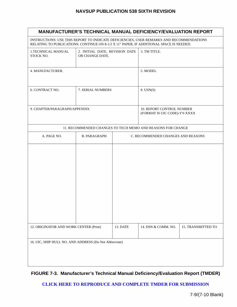
NAVSUP PUBLICATION 538 SIXTH REVISION
7-9/(7-10 Blank)
FIGURE 7-3. Manufacturer’s Technical Manual Deficiency/Evaluation Report (TMDER)
CLICK HERE TO REPRODUCE AND COMPLETE TMDER FOR SUBMISSION
MANUFACTURER’S TECHNICAL MANUAL DEFICIENCY/EVALUATION REPORT
INSTRUCTIONS: USE THIS REPORT TO INDICATE DEFICIENCIES, USER REMARKS AND RECOMMENDATIONSRELATING TO PUBLICATIONS. CONTINUE ON 8-1/2 X 11” PAPER, IF ADDITIONAL SPACE IS NEEDED.
1.TECHNICAL MANUAL STOCK NO.
2. INITIAL DATE, REVISION DATEOR CHANGE DATE.
3. TM TITLE.
4. MANUFACTURER. 5. MODEL
6. CONTRACT NO. 7. SERIAL NUMBERS 8. USN(S)
9. CHAPTER/PARAGRAPH/APPENDIX 10. REPORT CONTROL NUMBER(FORMAT IS UIC CODE)-YY-XXXX
11. RECOMMENDED CHANGES TO TECH MEMO AND REASONS FOR CHANGE
A. PAGE NO. B. PARAGRAPH C. RECOMMENDED CHANGES AND REASONS
12. ORIGINATOR AND WORK CENTER (Print) 13. DATE 14. DSN & COMM. NO. 15. TRANSMITTED TO
16. UIC, SHIP HULL NO. AND ADDRESS (Do Not Abbreviate)

This page left intentionally blank
NAVSUP PUBLICATION 538 SIXTH REVISION
8-1
CHAPTER 8
PREVENTIVE MAINTENANCE
8-1. GENERAL
The purpose of this chapter is to present the basic preventive maintenance practices which will assure the satisfactory performance of Materials Handling Equipment (MHE). For specific preventive maintenance, corrective maintenance, scheduled lubrication and inspection of safety devices, reference should also be made to the manufacturer’s technical manual that is supplied with the equipment.
8-2. RESPONSIBILITIES
Preventive maintenance and support funding is the direct responsibility of the MHE allowance holder of record and the indirect responsibility of personnel who operate MHE. For this reason, all personnel who operate MHE must satisfy the operator qualification requirements described in chapter 4. Likewise, to comply with American National Standards Institute/International Truck Standards Developing Foundation (ANSI/ITSDF) B56.1, maintenance and inspection on all powered industrial MHE and approved MHE attachments shall be performed in conformance with the following practices:
a. A scheduled planned maintenance, lubrication, and inspection system [e.g., Equipment Management and Control System (EMACS), Maintenance Material Management (3M) Manual, Maintenance Index Pages (MIPs) with their associated Maintenance Requirement Cards (MRC’s), etc.] shall be followed. Consult the manufacturer’s recommendations as well.
b. Only trained, knowledgeable or experienced personnel shall be authorized to maintain, repair, adjust, and inspect industrial MHE, and in accordance with manufacturer’s specifications.
8-2.1. OPERATOR RESPONSIBILITIES. MHE operators shall perform pre-operational and post-operational visual inspections and functional tests prior to placing any MHE in service. Likewise, all approved MHE attachments shall be visually inspected prior to being installed onto the MHE in accordance with the applicable MIP and the associated MRC’s (for Fork Extensions, Fork Stops or any MK/Mod ordnance handling equipment), NAVAIR 00-80R-19 (for Salvage Platforms), or other related documentation.
8-2.1.1. Powered MHE Operators.
NOTE
Refer to the appropriate MRC or technical manual for additional specific operating inspection procedures not addressed in the MHE Inspection Form, figure 8-1.

NAVSUP PUBLICATION 538 SIXTH REVISION
8-2
a. Initial Operator. The first operator shall conduct a daily pre-operational safety inspection of the MHE, using the inspection criteria provided, by completing the "START" portion of the MHE Inspection Form, figure 8-1, except:
(1) For aerial work platforms, refer to figure 8-2.
(2) For diesel conveyor belt vehicles, refer to figure 8-3.
(3) For mobile cargo cranes afloat, refer to table 589-3.2a, "Guidelines for Crane Daily Checklist", documented in NSTM S9086-T4-STM-010/CH-589 (includes Walk Around, Machinery House, Operator Cab and Operational Testing Inspection Criteria)
(4) For mobile cargo cranes ashore, refer to NAVFAC P-307. Only the applicable inspection criteria shall apply; procedures that do not apply may be obliterated for that particular MHE.
If the MHE passes all required inspections and functional tests, the applicable inspection form shall be signed and dated by the operator, and shall be attached to the MHE.
b. Subsequent Operators. When operational circumstances requires more than one operator to use the MHE during the course of a shift or evolution, the subsequent operators shall review the initial operator’s completed “START” portion of the applicable MHE Inspection Form. If the MHE is found acceptable, the original MHE Inspection Form shall remain with the MHE.
c. Last Operator. The last operator shall conduct a daily post-operational safety inspection of the MHE by completing the “FINISH” portion of the respective MHE Inspection Form. If no defects are noted, the MHE Inspection Form shall be maintained in accordance with local procedures.
d. Reporting Defects. All operators shall record all defects on the appropriate MHE Inspection Form, notify immediate supervisor of defects, and tag-out the unserviceable MHE for repairs in accordance with local procedures described in paragraph 8-2.1.3.
8-2.1.2. Non-Powered MHE Operators. Operators of non-powered MHE shall conduct inspections and functional tests in accordance with applicable MRC’s (afloat) or manufacturer’s technical manuals (ashore). Completion of the MHE Inspection Form is not required by the operator. If defects are found, notify immediate supervisor of defects and turn in the MHE for repairs in accordance with local procedures.
8-2.1.3. Local Procedural Requirements. As a minimum, all local procedures established shall stipulate the following:
a. A safety deficiency tag-out process, which includes procedures for tagging [e.g., “DO NOT OPERATE” tag (NAVSUP Form 1377/6), figure 8-6, red tag, caution, etc.] unserviceable MHE in a conspicuous location and for removing equipment under repair/service.
b. The appropriate MHE Inspection Form, described in paragraph 8-2.1.1a, shall be retained in the MHE history file only if defects are found and when repairs/tests have been completed.

NAVSUP PUBLICATION 538 SIXTH REVISION
8-3
8-2.2. MAINTENANCE PROVIDER RESPONSIBILITIES. When MHE is scheduled for preventive maintenance servicing, it should be cleaned and lubricated prior to receiving an inspection by authorized personnel. Upon completion of the preliminary servicing, a thorough inspection of the equipment, including an operational test and service inspection, shall be conducted. Preliminary servicing and inspections should be accomplished in accordance with EMACS, the 3M System, the applicable manufacturer’s technical manual, or local equivalent procedures, which authorizes minor adjustments to the equipment. If, however, the inspection indicates major adjustments or repairs, a work order using the EMACS program, 3M System, or local equivalent form shall outline the required maintenance for the equipment. One copy of the work order or local form will be retained in the equipment history file.
8-2.2.1. EMACS Program. Refer to chapter 6 for supporting EMACS program information and requirements.
8-2.2.2. Manufacturer’s Technical Manuals. The maintenance provider has the responsibility of maintaining the manufacturer’s technical manuals. These technical manuals provide recommended maintenance procedures, time schedules, lubrication schedules, principles of operation, a troubleshooting guide, repair instructions, and numerous other useful maintenance data relative to the specific types of MHE. They also contain illustrated parts breakdown of components and assemblies, including parts lists.

NAVSUP PUBLICATION 538 SIXTH REVISION
8-4
FIGURE 8-1. MHE Inspection Form
MHE INSPECTION FORM
DATE REGISTRATION NO. (USN) MHE CLASS (see table 4-1)
POWERED MHE TO BE CHECKED DAILY BY OPERATOR
NOTES
1. USE THIS FORM WHEN INSPECTING MHE BEFORE AND AFTER OPERATION.MARK APPROPRIATE COLUNMS TO INDICATE SATISFACTORY OR UNSATISFACTORY CONDITIONS.
2. NOT APPLICABLE INSPECTION PROCEDURES MAY BE OBLITERATED FOR THAT PARTICULAR MHE CLASS.
3. IF DEFECTS ARE FOUND, REMOVE MHE FROM SERVICE, NOTIFY IMMEDIATE SUPERVISOR AND RETAIN FORM UNTIL REPAIRS ARE MADE.
SHIFT HOUR-METER READING
4. IF NO DEFECTS ARE FOUND: END
(A) INITIAL OPERATOR: SIGN AND DATE FORM. ATTACH TO MHE. START
(B) LAST OPERATOR: MAINTAIN FORM IN ACCORDANCE WITH LOCAL PROCEDURES. DIFF.
5. THIS FORM IS NOT AVAILABLE IN THE SUPPLY SYSTEM. START FINISHREPRODUCTION OF THIS FORM FROM THIS MANUAL IS AUTHORIZED. SAT UNSAT SAT UNSAT
1 Tires and Rims 1
2 Engine Oil, Fluid Levels and Belts 2
3 Radiator Coolant Level (check when cool only) 3
4 Battery 4
5 Access Covers 5
6 Fuel System 6
7 Unusual Engine Noises 7
8 Lights 8
9 Horn 9
10 Hoist 10
11 Tilt and Side Shift 11
12 Transmission/Clutch 12
13 Directional Controls 13
14 Brake System 14
15 Gauges/Meters 15
16 Fire Extinguisher (if applicable) 16
17 Operator Restraint System (e.g., Seat Belts) 17
18 Forks 18
19 Fork Positioning Locks and Stops 19
20 Fork Safety Chains 20
21 Overhead Guard and Load Backrest 21
22 Ground Straps/Static Conductive Tires/Wheels 22
23 Structural Cracks/Broken Weldments 23
24 Mandatory Markings 24
ADDITIONAL OPTIONAL (NON-MANDATORY) INSPECTION REQUIREMENTS MAY BE INCLUDED HERE:
AREA INITIAL OPERATOR’S SIGNATURE LAST OPERATOR’S SIGNATURE
SEE REVERSE SIDE FOR INSPECTION CRITERIA PROCEDURES
Click Here to reproduce and annotate this form

NAVSUP PUBLICATION 538 SIXTH REVISION
8-5
MHE Inspection Form - Inspection Criteria1. Tires and Rims. Inspect tires for excessive wear and damage. Remove foreign material from tire treads. Reject tires for illegible or missing markings or labels.
Reject pneumatic tires when the tire tread has worn down to the tread wear mark or if fabric is exposed through the sidewall. Inspect the rims for dents, bends, and cracks. Refer to figure 8-7 for examples of solid rubber tire defects and the probable causes.
2. Engine Oil, Fluid Levels and Belts. Check engine oil, hydraulic, transmission and brake fluid levels. If low, add oil/fluid to raise the level to the full mark. Inspect engine belts for cracks, wear, damage, nicks or cuts, and proper tension. Always inspect floor/deck under MHE for any fluid puddles.
3. Radiator Coolant Levels. CAUTION: Do not check radiator coolant level when engine is hot. Check the radiator coolant level, if low, add coolant to the full mark.
4. Battery. Inspect battery cables for damage, cuts and abrasions. Verify cables are securely fastened to connector lugs and are free of corrosion, verdigris, arcing, pitting, exposed conductor material, and loose connections. Electric trucks have color coded battery indicator power band indicating remaining charge level. Charge battery when indicator drops into yellow zone (when under load; e.g., by tilting mast back against stop and check indicator). WARNING: For internal combustion start batteries, do not jump start battery with an eye cell indicator that appears yellow or clear (low fluid level) which may result in rupture.
5. Access Covers. Inspect all access covers (e.g., battery or engine) for loose, missing, broken, or corroded covers. Ensure latches snugly secure covers when fastened.
6. Fuel System. Visually inspect the entire fuel system assembly for any leaks or any abnormal odors. Where accessible, inspect the fuel tank or gas cylinder for leakage, denting, bulging, corrosion, pitting, gouges not exposed to fire, or evidence of rough usage. Valves are protected from physical damage.
7. Unusual Engine Noises. Start engine. Should any unusual noises be noted with the engine running, turn off MHE, reject and discontinue this check.8. Lights. Check that the headlights, brake lights, and any other installed lights are working. All lights must operate properly for night work.9. Horn. Depress the horn push button to verify that the horn is operating properly.10. Hoist and Lowering Control. Raise and lower the lifting assembly to verify the lifting assembly controls operate smoothly. Inspect all hoses for cracked
coverings, wear, bulges or leaks. Verify all fittings are free of cracks or leaks. Inspect for loose or binding (i.e., dry/not lubricated, frozen or rusted) chains. Inspect hose and cable reel guards, as applicable, for breaks, bends or chafing.
11. Tilt and Side Shift. Tilt forward and backward to verify the tilt operates smoothly. Operate side shift to verify the carriage moves immediately and smoothly to the left and the right. Verify all hoses are serviceable and that these fittings are free of cracks or leaks. For any additional accessory controls installed on the MHE; verify proper operation with the manufacturer’s recommendations.
12. Transmission/Clutch. Verify that the transmission/clutch operates smoothly with no unusual noises. Where applicable, test the neutral start switch on most fuel-powered MHE. Verify that the parking brake is set and that no one is in front of or behind the MHE. A periodic check can be made by attempting to start the engine with the directional control lever in either the forward or reverse position. If the engine starts, the MHE shall be rejected.
13. Directional Controls. Shift directional controls into forward, neutral and reverse directions to verify the MHE operates properly and smoothly. Figure 8-8 shows a typical example of the directional controls. Ensure steering operation functions smoothly.
14. Brake System Check. With the parking brake engaged, attempt to drive MHE forward by applying a moderate amount of power to the MHE and verify that it does not move. Visually inspect that no fluid is leaking from the brake system. Check the service brakes to verify they stop the MHE smoothly and evenly without pulling or binding. Where applicable, check the dead-man brake or travel control disconnect device for proper operation.
15. Gauges/Meters. Where applicable, inspect the following:a. Warning Indicators. With the engine running at normal operating temperature, check the oil pressure gauge (figure 8-9) for normal operating pressure. If
any warning indicator lights signal a malfunction, the MHE shall be rejected until repaired.b. Coolant Temperature Gauge. With the engine running at normal operating temperature, check that the gauge is indicating within the proper indicating
range. c. Fuel Gauge. Check the fuel gauge for proper reading. On types LP and CN MHE, the mechanical-type fuel gauge may be mounted directly on the gas tank.
Dual-fueled MHE shall not be operated unless the gasoline fuel tank is at least 1/4 full. Electric powered types should be in "green" power range.d. Voltmeter/Ammeter. With the engine running, check the voltmeter/ammeter to verify that its in the green range when the engine is running at least 550 rpm.e. Hourmeter. Verify that the hourmeter (figure 8-10) is registering while the engine is running.f. Weight Scales. With forks elevated, and no load, verify that the weight scales read zero. Adjust accordingly.
16. Fire Extinguisher. When equipped, visually inspect the extinguisher cylinder for dents. Check that the gauge is registering in the green (if so equipped) and check that the wire seal has not been broken. Verify periodic checks are current. Check nozzle and hose for defects. Reject extinguisher if not serviceable. Replace rejected extinguishers.
17. Operator Restraint System. If MHE is equipped with an operator restraint system (e.g., seat belt) it shall be inspected to verify that they fully extend out, can be properly secured, and fully retract back. Additionally, they shall not exhibit any evidence of the following discrepancies: (a) nicks or cuts (figure 8-11, view A), (b) frayed webbing (figure 8-11, view B), (c) holes (figure 8-11, view C), and (d) broken or worn retractor (figure 8-11, view D).
18. Forks. Visually examine the forks for surface cracks, including under the heel of the forks. Verify that blade and shank are straight, properly installed, and fork tips are even. Verify that load ratings of forks match MHE load rating. Surface cracks appearing on the forks shall be cause for rejection until forks are repaired or replaced.
19. Fork Positioning Locks/Stops. Verify the fork positioning locks/stops secure each fork in position. Verify forks are securely engaged to the carriage.20. Fork Safety Chains. Verify the presence and operation of fork safety chains (equipped on units with folding forks) and associated locking pins.21. Overhead Guards and Load Backrest. Inspect all welds and hardware. Verify that overhead guard, load backrest and hardware is in place and all structural
members are secured.22. Ground Straps or Static Conductive Tires/Wheels. For EE type MHE, verify the presence of two ground straps and that they touch the floor/deck or two
conductive tires/wheels. For EX type MHE, verify the presence of two conductive tires/wheels.23. Structural Cracks/Broken Weldments. Inspect all external weldments for structural cracks or defects. Reject MHE until repaired or replaced.24. Mandatory Markings. Verify the following is clearly and properly marked: (a) safe working load (SWL) and vehicle weight (VW) on both sides, and except for
pallet trucks, in view of operator, (b) operator controls, (c) manufacturer’s nameplate/label, (d) accredited laboratory (UL, FM) certification, (e) for tow tractors, the drawbar pull rating (DBP) on both sides and rear, and coupler height on rear, and (f) for ammunition and explosives handling only, the MHE Safety Certification marking (figure 5-9). Reject if the above markings are missing, illegible, expired or incorrect. All other required markings that are rejected shall be recorded on the MHE Inspection Form, but is not a cause for removal from service.
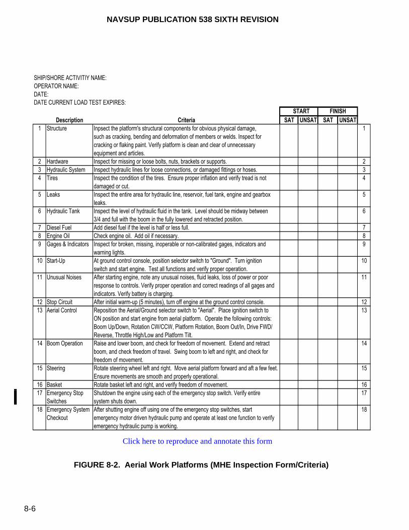
NAVSUP PUBLICATION 538 SIXTH REVISION
8-6
FIGURE 8-2. Aerial Work Platforms (MHE Inspection Form/Criteria)
SHIP/SHORE ACTIVITIY NAME:
OPERATOR NAME:
DATE:
DATE CURRENT LOAD TEST EXPIRES:
START FINISH
Description Criteria SAT UNSAT SAT UNSAT
1 Structure Inpsect the platform's structural components for obvious physical damage, 1
such as cracking, bending and deformation of members or welds. Inspect for
cracking or flaking paint. Verify platform is clean and clear of unnecessary
equipment and articles.
2 Hardware Inspect for missing or loose bolts, nuts, brackets or supports. 2
3 Hydraulic System Inspect hydraulic lines for loose connections, or damaged fittings or hoses. 3
4 Tires Inspect the condition of the tires. Ensure proper inflation and verify tread is not 4
damaged or cut.
5 Leaks Inspect the entire area for hydraulic line, reservoir, fuel tank, engine and gearbox 5
leaks.
6 Hydraulic Tank Inspect the level of hydraulic fluid in the tank. Level should be midway between 6
3/4 and full with the boom in the fully lowered and retracted position.
7 Diesel Fuel Add diesel fuel if the level is half or less full. 7
8 Engine Oil Check engine oil. Add oil if necessary. 8
9 Gages & Indicators Inspect for broken, missing, inoperable or non-calibrated gages, indicators and 9
warning lights.
10 Start-Up At ground control console, position selector switch to "Ground". Turn ignition 10
switch and start engine. Test all functions and verify proper operation.
11 Unusual Noises After starting engine, note any unusual noises, fluid leaks, loss of power or poor 11
response to controls. Verify proper operation and correct readings of all gages and
indicators. Verify battery is charging.
12 Stop Circuit After initial warm-up (5 minutes), turn off engine at the ground control console. 12
13 Aerial Control Reposition the Aerial/Ground selector switch to "Aerial". Place ignition switch to 13
ON position and start engine from aerial platform. Operate the following controls:
Boom Up/Down, Rotation CW/CCW, Platform Rotation, Boom Out/In, Drive FWD/
Reverse, Throttle High/Low and Platform Tilt.
14 Boom Operation Raise and lower boom, and check for freedom of movement. Extend and retract 14
boom, and check freedom of travel. Swing boom to left and right, and check for
freedom of movement.
15 Steering Rotate steering wheel left and right. Move aerial platform forward and aft a few feet. 15
Ensure movements are smooth and properly operational.
16 Basket Rotate basket left and right, and verify freedom of movement. 16
17 Emergency Stop Shutdown the engine using each of the emergency stop switch. Verify entire 17
Switches system shuts down.
18 Emergency System After shutting engine off using one of the emergency stop switches, start 18
Checkout emergency motor driven hydraulic pump and operate at least one function to verify
emergency hydraulic pump is working.
Click here to reproduce and annotate this form
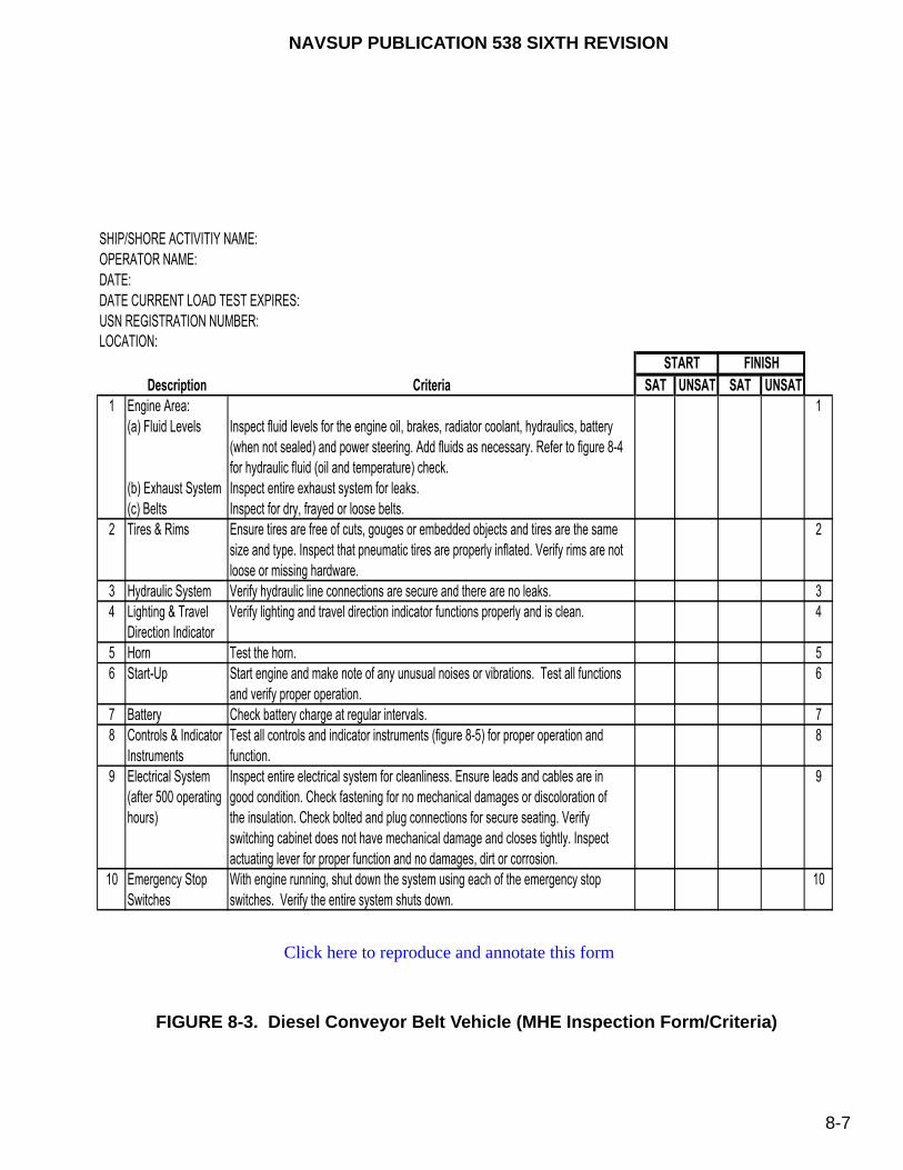
NAVSUP PUBLICATION 538 SIXTH REVISION
8-7
FIGURE 8-3. Diesel Conveyor Belt Vehicle (MHE Inspection Form/Criteria)
SHIP/SHORE ACTIVITIY NAME:
OPERATOR NAME:
DATE:
DATE CURRENT LOAD TEST EXPIRES:
USN REGISTRATION NUMBER:
LOCATION:
START FINISH
Description Criteria SAT UNSAT SAT UNSAT
1 Engine Area: 1
(a) Fluid Levels Inspect fluid levels for the engine oil, brakes, radiator coolant, hydraulics, battery
(when not sealed) and power steering. Add fluids as necessary. Refer to figure 8-4
for hydraulic fluid (oil and temperature) check.
(b) Exhaust System Inspect entire exhaust system for leaks.
(c) Belts Inspect for dry, frayed or loose belts.
2 Tires & Rims Ensure tires are free of cuts, gouges or embedded objects and tires are the same 2
size and type. Inspect that pneumatic tires are properly inflated. Verify rims are not
loose or missing hardware.
3 Hydraulic System Verify hydraulic line connections are secure and there are no leaks. 3
4 Lighting & Travel Verify lighting and travel direction indicator functions properly and is clean. 4
Direction Indicator
5 Horn Test the horn. 5
6 Start-Up Start engine and make note of any unusual noises or vibrations. Test all functions 6
and verify proper operation.
7 Battery Check battery charge at regular intervals. 7
8 Controls & Indicator Test all controls and indicator instruments (figure 8-5) for proper operation and 8
Instruments function.
9 Electrical System Inspect entire electrical system for cleanliness. Ensure leads and cables are in 9
(after 500 operating good condition. Check fastening for no mechanical damages or discoloration of
hours) the insulation. Check bolted and plug connections for secure seating. Verify
switching cabinet does not have mechanical damage and closes tightly. Inspect
actuating lever for proper function and no damages, dirt or corrosion.
10 Emergency Stop With engine running, shut down the system using each of the emergency stop 10
Switches switches. Verify the entire system shuts down.
Click here to reproduce and annotate this form
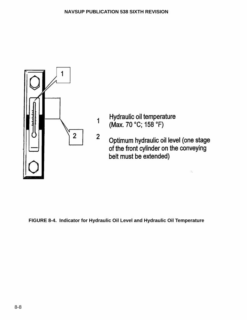
NAVSUP PUBLICATION 538 SIXTH REVISION
8-8
FIGURE 8-4. Indicator for Hydraulic Oil Level and Hydraulic Oil Temperature

NAVSUP PUBLICATION 538 SIXTH REVISION
8-9
FIGURE 8-5. Control and Indicator Instruments (1 of 2)
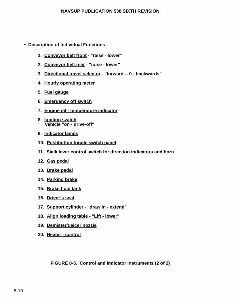
NAVSUP PUBLICATION 538 SIXTH REVISION
8-10
FIGURE 8-5. Control and Indicator Instruments (2 of 2)
• Description of Individual Functions
1. Conveyor belt front - "raise - lower"
2. Conveyor belt rear - "raise - lower"
3. Directional travel selector - "forward -- 0 - backwards"
4. Hourly operating meter
5. Fuel gauge
6. Emergency off switch
7. Engine oil - temperature indicator
8. Ignition switchVehicle "on - drive-off"
9. Indicator lamps
10. Pushbutton toggle switch panel
11. Stalk lever control switch for direction indicators and horn
12. Gas pedal
13. Brake pedal
14. Parking brake
15. Brake fluid tank
16. Driver’s seat
17. Support cylinder - "draw in - extend"
18. Align loading table - "Lift - lower"
19. Demister/deicer nozzle
20. Heater - control

NAVSUP PUBLICATION 538 SIXTH REVISION
8-11
FIGURE 8-6. “DO NOT OPERATE” Tag

NAVSUP PUBLICATION 538 SIXTH REVISION
8-12
FIGURE 8-7. Solid Rubber Tire Defects
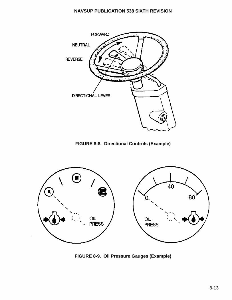
NAVSUP PUBLICATION 538 SIXTH REVISION
8-13
FIGURE 8-8. Directional Controls (Example)
FIGURE 8-9. Oil Pressure Gauges (Example)

NAVSUP PUBLICATION 538 SIXTH REVISION
8-14
FIGURE 8-10. Engine Hourmeter
8-2.2.3. Capabilities. The maintenance provider has the responsibility to ensure adequate capabilities to service all types of MHE and to efficiently handle the anticipated workload. These capabilities should include adjustable lifts, lubrication and cleaning equipment, power tools, test equipment, and various types of hand tools necessary to repair and adjust the equipment. Only the correct tools should be used to make repairs.
8-3. EQUIPMENT HISTORY FILE
Every piece of MHE used ashore and afloat requires an equipment history file. For ashore mobile cargo cranes, refer to NAVFAC P-307 for additional equipment history file requirements. It is the responsibility of the maintenance provider to initiate and maintain an equipment history file. For units originally delivered to the NAVSUP Fleet Logistics Center (NAVSUP FLC) [formerly Fleet and Industrial Supply Center (FISC)], the Regional Manager will initiate all equipment history files. The information recorded will provide a complete history of the equipment and it’s service life. In the event MHE is transferred to another activity, the equipment history file shall accompany the MHE. The history file shall be maintained throughout the MHE life cycle.
8-3.1. MANDATORY DOCUMENTATION. A typical history file shall include the following:
a. Maintenance actions (repairs or preventive), cost, materials/parts and inspection data.

NAVSUP PUBLICATION 538 SIXTH REVISION
8-15
NOTE
Although this data can reside on an electronic database, hard copy reports/forms are required in the equipment history file.
b. All shipping and receiving (e.g., DD-1149 Form) and commercial acceptance (e.g., DD-250 Form) documentation.
c. Weight test certification documentation.
d. Annual fork inspection certification documentation.
e. Any proposed or approved MHE modifications or alterations.
8-3.2. OPTIONAL DOCUMENTATION. A typical equipment history file should include the following, as applicable:
a. Periodic hours of operation reports, if available.
b. Any pertinent correspondence (e.g., letters or messages).
c. A copy of the MHE ISEA endorsement that the safety rating has been maintained when the accredited laboratory certification identification, such as Underwriters’ Laboratory (UL) or Factory Mutual (FM), is missing or illegible on the MHE.
8-3.3. SLEP DOCUMENTATION. If a piece of equipment has gone through the Service Life Extension Program (SLEP), the old equipment history file will be archived by the applicable FICP, who will initiate a new history file containing the following information:
a. SLEP estimates and parts replaced.
b. SLEP engine test results.
c. SLEP MHE Final Inspection Form.
8-4. NEW OR SLEP EQUIPMENT
Mast and fork restraint devices must be removed prior to operating components to prevent damage to the MHE.
All new equipment from direct vendor delivery or a Service Life Extension Program (SLEP) unit from a SLEP facility must receive an initial receipt inspection and servicing in accordance with the MHE Initial Receipt Inspection Form, figure 8-12. Prior to conducting these inspections, remove any restraint devices (e.g., stops, blocks, etc.), which would prevent the MHE from operating properly. Also, remove any covers, cardboard protectors, engine exhaust or breather vent covers, etc., which would restrict the
CAUTION
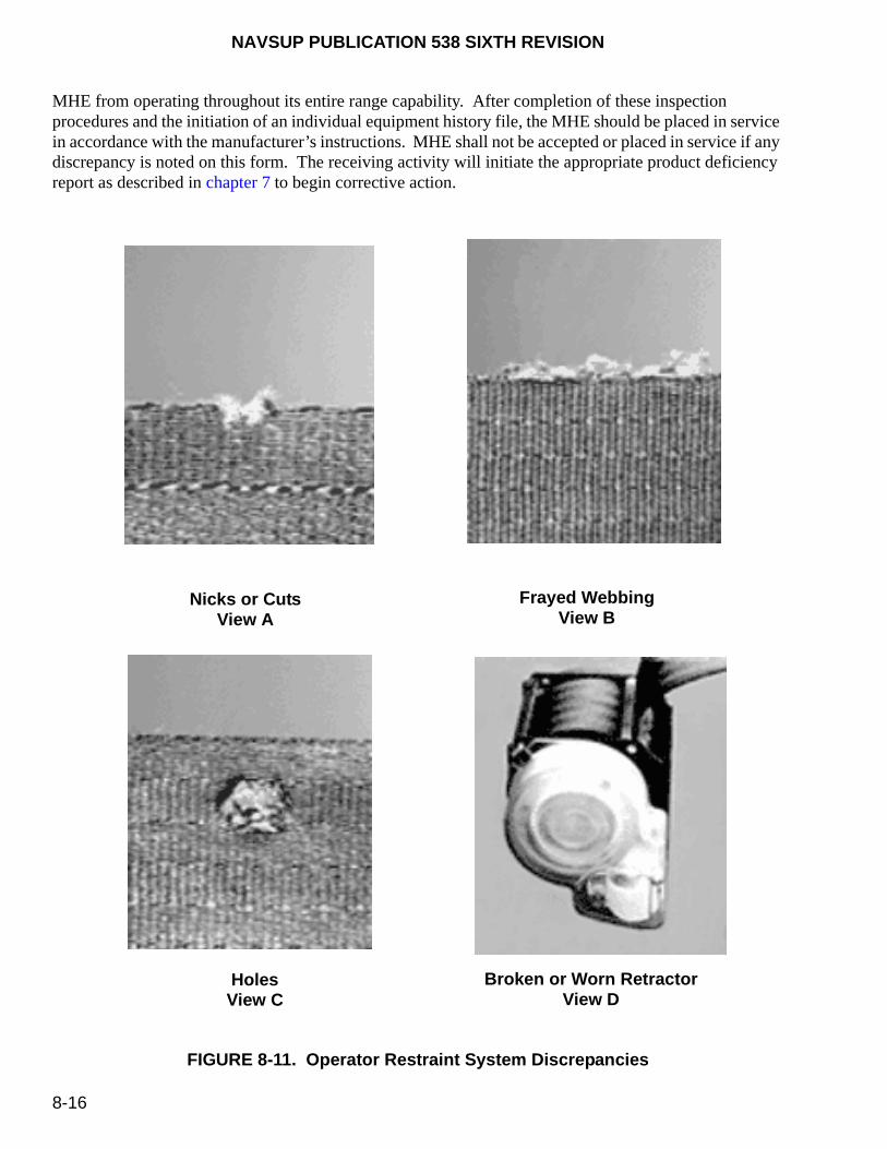
NAVSUP PUBLICATION 538 SIXTH REVISION
8-16
MHE from operating throughout its entire range capability. After completion of these inspection procedures and the initiation of an individual equipment history file, the MHE should be placed in service in accordance with the manufacturer’s instructions. MHE shall not be accepted or placed in service if any discrepancy is noted on this form. The receiving activity will initiate the appropriate product deficiency report as described in chapter 7 to begin corrective action.
FIGURE 8-11. Operator Restraint System Discrepancies
Nicks or CutsView A
Frayed WebbingView B
HolesView C
Broken or Worn RetractorView D
NAVSUP PUBLICATION 538 SIXTH REVISION
8-17
8-5. PREVENTIVE MAINTENANCE SCHEDULING
Each activity, afloat or ashore, must establish a preventive maintenance program, based on manufacturer’s technical manual recommendations, or applicable MIP and their associated MRC’s appropriate for local operating conditions. This program should include:
a. A planned program of periodic inspections and maintenance based on active MHE operation as measured by established maintenance cycles.
b. A capable maintenance provider. For units afloat, maintain MHE in accordance with Planned Maintenance System (PMS) and Type Commander (TYCOM) programs.
c. An accurate reporting system [e.g., EMACS or hard copy procedures for ashore activities; for units afloat, the applicable maintenance data system as directed by OPNAVINST 4790.4 (series)], since it is essential that repair requests and maintenance procedures are recorded. This reporting system must be maintained for each piece of equipment and must be periodically reviewed for general equipment conditions and indications of repetitive malfunctions on the same component or assembly. Periodic and unscheduled maintenance should be documented in the equipment history file.
d. A planned program for reporting technical deficiencies or changes to inspection and maintenance procedures documented in associated MIP’s/MRC’s. A Technical Feedback Report (TFBR) shall be completed by originators and submitted to Commanding Officer, Naval Logistics Center (NAVSEALOGCEN) Detachment San Diego, Code 05316, 4755 Railroad Way, San Diego, CA 92136-5503 in accordance with the instructions of OPNAVINST 4790.4 (series). All feedback reports will be thoroughly investigated and those who provided the comments will be advised of the outcome.
MRC’s identify the minimum (scheduled) periodicity for which that particular task must be accomplished to maintain the MHE at a fully operational condition. However, MRC procedures can be accomplished more frequently than prescribed due to harsh weather, unusual operating conditions, outside storage, corrective maintenance, and because of test requirements. For example, if operational requirements dictate that a forklift truck (normally stowed within the ship) must be stowed outside on the weather deck, the maintenance procedures would be performed sooner on an as needed basis. In this example, a TFBR would not be required unless outside stowage requirements becomes part of local operating procedures, thus increasing scheduled maintenance. Typically, electric MHE contain extremely delicate electronic components that when used or stored outdoors will cause failures due to moisture.
There are two major areas that require lubrication more frequently than scheduled to ensure that the MHE is fully operational at all times. Lubrication on dry, bare metal components serve as the only barrier of protection against harsh environments.
8-5.1. LUBRICATING LIFT CHAINS. The minimum PMS periodicity requirement to lubricate the lift chains is semi-annually. However, during inspection, if the operator detects that the lift chains are dry, the unit should be lubricated sooner than its scheduled periodicity. They should never become rusted or frozen.
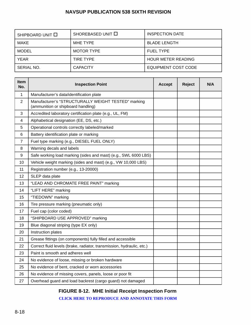
NAVSUP PUBLICATION 538 SIXTH REVISION
8-18
SHIPBOARD UNIT SHOREBASED UNIT INSPECTION DATE
MAKE MHE TYPE BLADE LENGTH
MODEL MOTOR TYPE FUEL TYPE
YEAR TIRE TYPE HOUR METER READING
SERIAL NO. CAPACITY EQUIPMENT COST CODE
ItemNo.
Inspection Point Accept Reject N/A
1 Manufacturer’s data/identification plate
2 Manufacturer’s “STRUCTURALLY WEIGHT TESTED” marking(ammunition or shipboard handling)
3 Accredited laboratory certification plate (e.g., UL, FM)
4 Alphabetical designation (EE, DS, etc.)
5 Operational controls correctly labeled/marked
6 Battery identification plate or marking
7 Fuel type marking (e.g., DIESEL FUEL ONLY)
8 Warning decals and labels
9 Safe working load marking (sides and mast) (e.g., SWL 6000 LBS)
10 Vehicle weight marking (sides and mast) (e.g., VW 10,000 LBS)
11 Registration number (e.g., 13-20000)
12 SLEP data plate
13 “LEAD AND CHROMATE FREE PAINT” marking
14 “LIFT HERE” marking
15 “TIEDOWN” marking
16 Tire pressure marking (pneumatic only)
17 Fuel cap (color coded)
18 “SHIPBOARD USE APPROVED” marking
19 Blue diagonal striping (type EX only)
20 Instruction plates
21 Grease fittings (on components) fully filled and accessible
22 Correct fluid levels (brake, radiator, transmission, hydraulic, etc.)
23 Paint is smooth and adheres well
24 No evidence of loose, missing or broken hardware
25 No evidence of bent, cracked or worn accessories
26 No evidence of missing covers, panels, loose or poor fit
27 Overhead guard and load backrest (cargo guard) not damaged
FIGURE 8-12. MHE Initial Receipt Inspection Form
CLICK HERE TO REPRODUCE AND ANNOTATE THIS FORM

NAVSUP PUBLICATION 538 SIXTH REVISION
8-19
28 Forks are straight within 1% of length
29 Hydraulic cylinders: no weld cracks, leaks or other damage
30 Neoprene hydraulic lines: free of paint, routed correctly and secured
31 Towing devices, hitch pins, tow chains, etc. are attached
32 Battery cables: secure, no cuts/abrasions, and protected by non-conductive covers
33 Battery mounts and hold downs are secure
34 Wiring harness is correct with no frayed, brittle or crimped connections (soldered only)
35 Tires are correct type, size and thread (no delamination shall be accepted)
36 Wheel lugs are torqued as specified
37 Check mast rollers and locks
38 Fork heel pins and locks function
39 Lift chains and anchor pins are secure and functional
40 Operator pedals are equipped with rubber pads or non-slip coating
41 Operator restraint system/seat belt equipped and functional
42 Dash gauges are correct and marked
43 Key ignition switch (verify key numbers match contract numbers)
44 Start MHE and note any unusual noises
45 Weight gauge is legible and operable
46 Steering wheel is smooth and little free play
47 Verify all gauges function
48 Verify hourmeter operates properly
49 Verify horn operates
50 Verify back-up alarm operates
51 Verify all lights operate: brake, spot, battle/blackout, etc.
52 No evidence of steering play or loose suspension
53 Bring to full operating temperature (fuel power only) and check for leaks
54 Check for arcing and operation of contactors, traction, steer and hydraulic pump motors (electric MHE only)
55 Battery disconnect switch is operable
56 Check accelerator and inching/declutching pedal operation
57 Check brake operation
ItemNo.
Inspection Point Accept Reject N/A
FIGURE 8-12. MHE Initial Receipt Inspection Form (Continued)CLICK HERE TO REPRODUCE AND ANNOTATE THIS FORM
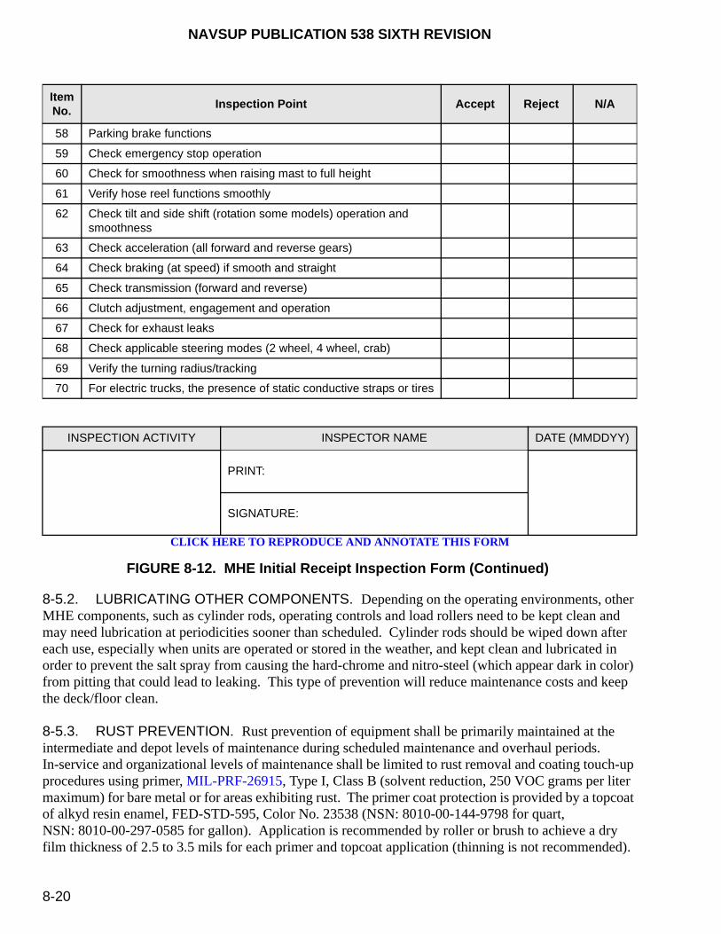
NAVSUP PUBLICATION 538 SIXTH REVISION
8-20
8-5.2. LUBRICATING OTHER COMPONENTS. Depending on the operating environments, other MHE components, such as cylinder rods, operating controls and load rollers need to be kept clean and may need lubrication at periodicities sooner than scheduled. Cylinder rods should be wiped down after each use, especially when units are operated or stored in the weather, and kept clean and lubricated in order to prevent the salt spray from causing the hard-chrome and nitro-steel (which appear dark in color) from pitting that could lead to leaking. This type of prevention will reduce maintenance costs and keep the deck/floor clean.
8-5.3. RUST PREVENTION. Rust prevention of equipment shall be primarily maintained at the intermediate and depot levels of maintenance during scheduled maintenance and overhaul periods. In-service and organizational levels of maintenance shall be limited to rust removal and coating touch-up procedures using primer, MIL-PRF-26915, Type I, Class B (solvent reduction, 250 VOC grams per liter maximum) for bare metal or for areas exhibiting rust. The primer coat protection is provided by a topcoat of alkyd resin enamel, FED-STD-595, Color No. 23538 (NSN: 8010-00-144-9798 for quart, NSN: 8010-00-297-0585 for gallon). Application is recommended by roller or brush to achieve a dry film thickness of 2.5 to 3.5 mils for each primer and topcoat application (thinning is not recommended).
ItemNo.
Inspection Point Accept Reject N/A
58 Parking brake functions
59 Check emergency stop operation
60 Check for smoothness when raising mast to full height
61 Verify hose reel functions smoothly
62 Check tilt and side shift (rotation some models) operation and smoothness
63 Check acceleration (all forward and reverse gears)
64 Check braking (at speed) if smooth and straight
65 Check transmission (forward and reverse)
66 Clutch adjustment, engagement and operation
67 Check for exhaust leaks
68 Check applicable steering modes (2 wheel, 4 wheel, crab)
69 Verify the turning radius/tracking
70 For electric trucks, the presence of static conductive straps or tires
INSPECTION ACTIVITY INSPECTOR NAME DATE (MMDDYY)
PRINT:
SIGNATURE:
FIGURE 8-12. MHE Initial Receipt Inspection Form (Continued)
CLICK HERE TO REPRODUCE AND ANNOTATE THIS FORM

NAVSUP PUBLICATION 538 SIXTH REVISION
8-21
8-6. FORK MAINTENANCE INSPECTION PROCEDURES
As required by ANSI/ITSDF B56.1, forks shall be inspected and documented in the MHE's history file at intervals of not more than 12 months or whenever any defect or permanent deformation is detected. To satisfy the requirement, all MHE forks shall be inspected in accordance with the Fork Maintenance Inspection Form, figure 8-13. Procedures are documented on the back of the Fork Maintenance Inspection Form to support each inspection criteria. Such inspections and subsequent certification should be performed by a maintenance provider or local mechanic knowledgeable on MHE. Any fork defect shall be a cause for the MHE to be removed from service until the fork is repaired or replaced. Only the fork manufacturer or their designated representative shall be authorized to repair forks. Fork components are illustrated in figure 8-14.
8-7. MAINTAINING SAFETY INTEGRITY OF MHE
Adherence to the recommendations, service notes, and maintenance procedures contained in the applicable manufacturer’s technical manuals will maximize personnel safety and equipment efficiency during materials handling operations. All repairs to MHE must follow the safeguards in the manufacturer’s technical manual safety section (green pages) to maintain the proper safety rating. The exact parts identified within those pages must be used when repairs are made to avoid comprising the unit’s safety rating. For deployed ships, if maintenance operations or repairs require the MHE to be weight tested (safety certification), contact the Type Commander (TYCOM), who will then contact the MHE ISEA at the Naval PHST Center for direction and interim approval for such testing. Upon return, the ship must transfer the MHE to a certified test facility [i.e., local NAVSUP Fleet Logistics Center (NAVSUP FLC)] for re-certification testing in accordance with this publication.
8-7.1. MAINTENANCE PERSONNEL PRECAUTIONS. To maintain the integrity of MHE, the following precautions shall be observed by maintenance personnel concerned with servicing and repairing industrial MHE:
a. Only trained and authorized personnel shall perform repairs using manufacturer instructions. Replacement parts must meet the manufacturer specifications.
b. For ashore activities, when parts are replaced, an entry shall be recorded in the equipment history file and the respective maintenance data system (e.g., EMACS, hard copy procedures, or other maintenance data management systems) identifying the replaced part(s) by manufacturer’s name, catalog and part number. The name of the person replacing the part(s), the date, and the activity’s name shall also be recorded.
c. For units afloat, when parts are replaced, an entry shall be recorded in the equipment history file as directed by OPNAVINST 4790.4 (series) identifying the replaced part(s) by manufacturer’s name, catalog and part number. The name of the person replacing the part(s), the date, and the activity’s name shall also be recorded.
d. All repairs shall be performed in approved areas as required by 29 CFR 1910.178.
e. Safety devices, described in paragraph 5-4, and components removed, such as covers, panels, etc., must be reinstalled upon completion of repairs to maintain the integrity of the safety rating.

NAVSUP PUBLICATION 538 SIXTH REVISION
8-22
CLICK HERE TO REPRODUCE AND ANNOTATE THIS FORM
FORK MAINTENANCE INSPECTION FORM (Dated 11/15/02)
USN: _____ - ___________
Manufacturer’: ____________ Model: _________ Year: _____ Serial Number: ________
Contract Number: _______________________
REQUIREMENTEach fork shall be inspected and documented in the MHE history file at intervals of not more than 12 months or whenever any defect or permanent deformation is detected. Any defect shall be a cause for rejection. MHE shall be removed from service until the fork is repaired or replaced.
DESCRIPTIONLEFT FORK RIGHT FORK Not
Applica-bleSAT UNSAT SAT UNSAT
1. Manufacturer’s SWL Markings
2. Surface Cracks
3. Straightness of Blade and Shank:(a) Upper Face of Blade(b) Front Face of Shank
4. Fork Angle: (original specification = _______)
5. Difference in Height of Fork Tips:(Length of blade = __ inches x 0.03 = ___ inches)
6. Fork Blades:Left Fork:
original thickness = ___ inches x 0.10 = ___ inches current thickness = ___ inches
Right Fork: original thickness = ___ inches x 0.10 = ___ inches current thickness = ___ inches
7. Positioning Locks/Latches and Stops (where applicable)
8. Fork Hooks (where applicable)
9. Plated Fork (Type EX Only)
Inspection results: Based on the above inspections, the overall condition of each fork is:
Left Fork: SAT/UNSAT Right Fork: SAT/UNSAT
Inspector: ___________________________ Date: _______ Next Due Date: _______
Print Name/Rate:_______________________ Inspection Activity:___________________
SEE NEXT PAGE FOR INSPECTION CRITERIA PROCEDURES
FIGURE 8-13. Fork Maintenance Inspection Form
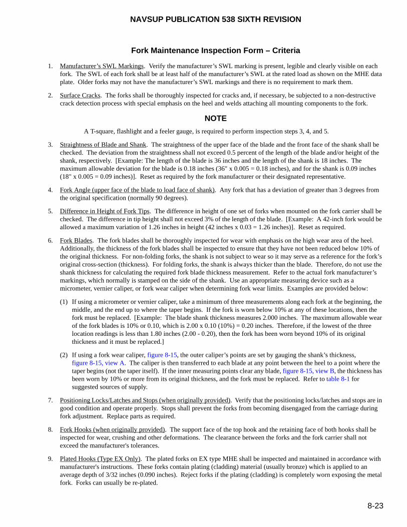
NAVSUP PUBLICATION 538 SIXTH REVISION
8-23
Fork Maintenance Inspection Form – Criteria
1. Manufacturer’s SWL Markings. Verify the manufacturer’s SWL marking is present, legible and clearly visible on each fork. The SWL of each fork shall be at least half of the manufacturer’s SWL at the rated load as shown on the MHE data plate. Older forks may not have the manufacturer’s SWL markings and there is no requirement to mark them.
2. Surface Cracks. The forks shall be thoroughly inspected for cracks and, if necessary, be subjected to a non-destructive crack detection process with special emphasis on the heel and welds attaching all mounting components to the fork.
NOTE
A T-square, flashlight and a feeler gauge, is required to perform inspection steps 3, 4, and 5.
3. Straightness of Blade and Shank. The straightness of the upper face of the blade and the front face of the shank shall be checked. The deviation from the straightness shall not exceed 0.5 percent of the length of the blade and/or height of the shank, respectively. [Example: The length of the blade is 36 inches and the length of the shank is 18 inches. The maximum allowable deviation for the blade is 0.18 inches (36" x 0.005 = 0.18 inches), and for the shank is 0.09 inches (18" x 0.005 = 0.09 inches)]. Reset as required by the fork manufacturer or their designated representative.
4. Fork Angle (upper face of the blade to load face of shank). Any fork that has a deviation of greater than 3 degrees from the original specification (normally 90 degrees).
5. Difference in Height of Fork Tips. The difference in height of one set of forks when mounted on the fork carrier shall be checked. The difference in tip height shall not exceed 3% of the length of the blade. [Example: A 42-inch fork would be allowed a maximum variation of 1.26 inches in height (42 inches x 0.03 = 1.26 inches)]. Reset as required.
6. Fork Blades. The fork blades shall be thoroughly inspected for wear with emphasis on the high wear area of the heel. Additionally, the thickness of the fork blades shall be inspected to ensure that they have not been reduced below 10% of the original thickness. For non-folding forks, the shank is not subject to wear so it may serve as a reference for the fork’s original cross-section (thickness). For folding forks, the shank is always thicker than the blade. Therefore, do not use the shank thickness for calculating the required fork blade thickness measurement. Refer to the actual fork manufacturer’s markings, which normally is stamped on the side of the shank. Use an appropriate measuring device such as a micrometer, vernier caliper, or fork wear caliper when determining fork wear limits. Examples are provided below:
(1) If using a micrometer or vernier caliper, take a minimum of three measurements along each fork at the beginning, the middle, and the end up to where the taper begins. If the fork is worn below 10% at any of these locations, then the fork must be replaced. [Example: The blade shank thickness measures 2.000 inches. The maximum allowable wear of the fork blades is 10% or 0.10, which is 2.00 x 0.10 (10%) = 0.20 inches. Therefore, if the lowest of the three location readings is less than 1.80 inches (2.00 - 0.20), then the fork has been worn beyond 10% of its original thickness and it must be replaced.]
(2) If using a fork wear caliper, figure 8-15, the outer caliper’s points are set by gauging the shank’s thickness, figure 8-15, view A. The caliper is then transferred to each blade at any point between the heel to a point where the taper begins (not the taper itself). If the inner measuring points clear any blade, figure 8-15, view B, the thickness has been worn by 10% or more from its original thickness, and the fork must be replaced. Refer to table 8-1 for suggested sources of supply.
7. Positioning Locks/Latches and Stops (when originally provided). Verify that the positioning locks/latches and stops are in good condition and operate properly. Stops shall prevent the forks from becoming disengaged from the carriage during fork adjustment. Replace parts as required.
8. Fork Hooks (when originally provided). The support face of the top hook and the retaining face of both hooks shall be inspected for wear, crushing and other deformations. The clearance between the forks and the fork carrier shall not exceed the manufacturer's tolerances.
9. Plated Hooks (Type EX Only). The plated forks on EX type MHE shall be inspected and maintained in accordance with manufacturer's instructions. These forks contain plating (cladding) material (usually bronze) which is applied to an average depth of 3/32 inches (0.090 inches). Reject forks if the plating (cladding) is completely worn exposing the metal fork. Forks can usually be re-plated.

NAVSUP PUBLICATION 538 SIXTH REVISION
8-24
FIGURE 8-14. Fork Components
FIGURE 8-15. Fork Wear Caliper

NAVSUP PUBLICATION 538 SIXTH REVISION
8-25
8-7.2. PERIODIC WEIGHT TESTING OF FORKLIFT ATTACHMENTS. The Mk 12 Mod 0 Fork Extension, the Fork Stop, Personnel Baskets, or Salvage Platforms, as identified in paragraph 3-3, do not require a periodic weight test. Refer to NAVSEA SW023-AH-WHM-010 for periodic weight testing requirements for other types of MHE attachments designated to handle ordnance.
All shipboard forklift and electric pallet trucks, or ashore forklift and electric pallet trucks designated to handle ammunition and explosives are subjected to the operational or overload weight testing requirements documented in NAVSEA SW023-AH-WHM-010. The operational weight testing requirements prescribed in paragraphs 8-7.3 and 8-7.4 shall only apply to ashore units designated to handle general supply and HAZMAT (other than ammunition and explosives).
8-7.3. OPERATIONAL WEIGHT TESTING (ALL FORKLIFT TRUCKS). Whenever ashore forklift trucks (for non-ammunition and explosives handling) have undergone repairs or modifications affecting any load-bearing component (i.e., forks, fork carriage, cylinders, frame or mast), the following operational weight test shall be performed and recorded in the equipment history file:
NOTE
Ashore forklift trucks (assigned for ammunition and explosives handling) and all shipboard forklift trucks shall comply with the overload weight testing requirements documented in NAVSEA SW023-AH-WHM-010.
a. Ensure the forklift truck is on a level surface.
b. Position a rated load (100% of the forklift truck’s SWL) on the forks with the center of mass at the load center. Ensure the load is centered laterally. If weights are used and stacked more than two high, the safety officer or supervisor shall determine whether the weights are stable prior to proceeding with these tests. If instability of weights has been determined, they must be secured with steel strapping or chains. Raise the loaded forks 6 inches off the deck/floor, tilt full back, and hold for 2 minutes.
Table 8-1. Fork Wear Caliper (Suggested Source of Supply)
Vendor Product Order No. Phone No. Internet
Iron Works, Inc. Forks Inspection Kit IWIFORKCAL 800-221-6572 [email protected]
Barclay Brand Ferdon
Cascade Fork Safety Inspection Kit
150019386 800-248-9253 www.bbfyale.com
(When ordering from the vendor, please specify that you are with the "U.S. Navy".)
WARNING

NAVSUP PUBLICATION 538 SIXTH REVISION
8-26
When the mast is fully raised, ensure the operator’s hands are clear of the controls and the person marking and verifying the height is positioned to the side of the forklift truck. An observer must ensure that all personnel are clear of the mast prior to raising the rated load.
c. Shift lateral to full limits and then raise load to full mast extension. Repeat lateral shift operation and then return load to deck/floor.
NOTE
The following steps must be performed with the hydraulic system at normal operating temperatures. This may accomplished by raising and lowering the mast five times.
d. With the mast vertical, forks centered, and the rated load on the forks, raise the forks to the maximum height. Mark a reference point on the mast or measure the carriage to a reference point on the fixed portion of the mast. If the forklift truck has a tilting mast (e.g., standard forklift truck), mark a reference point on the tilt cylinders or obtain an initial measurement on the mast angle.
e. After 2 minutes, measure the downward and tilt drift, as applicable, from the reference points.
NOTE
Perform steps f through h on forklift trucks that have tilting carriages (e.g., sideloader and reaching and tiering forklift trucks).
f. Lower the forks to just above the outriggers or to the lowest point allowed by the centering limit switch, if so equipped.
g. Tilt the carriage rearward to its limit. Release the tilt lever.
h. After 2 minutes, tilt the fork carriage rearward again. Note any movement.
i. Lower and remove the load.
The forklift truck shall be rejected if the mast drift vertically more than 1-3/4 inches. If equipped with a tilting mast, the forklift truck shall be rejected if it tilts more than one degree. If equipped with a tilting carriage, the forklift truck shall be rejected if any movement is noted when tilting the carriage rearward the second time. The forklift truck shall be rejected if it lifts, shifts or tilts the load too slowly or unevenly, the hoses and tubing have bulges or distortion, the frame and mast assembly have fractures or broken welds, or if the forklift truck leaks hydraulic fluid. When raising or lowering the mast, if the forklift truck does not operate freely and/or binds or catches on the overhead guard or any other component, it shall be rejected.
WARNING

NAVSUP PUBLICATION 538 SIXTH REVISION
8-27
8-7.4. OPERATIONAL WEIGHT TESTING (ALL POWERED PALLET TRUCKS). Whenever ashore powered pallet trucks (for non-ammunition and explosives handling) have undergone repairs or modifications affecting any load-bearing component (i.e., forks, cylinders or frame), the following operational weight test shall be performed and recorded in the equipment history file:
NOTE
Ashore powered pallet trucks (assigned for ammunition and explosives handling) and all shipboard powered pallet trucks shall comply with the overload weight testing requirements documented in NAVSEA SW023-AH-WHM-010.
a. Ensure the powered pallet truck is on a level surface.
b. Position a rated load (100% of the pallet truck’s SWL) on the forks with the center of mass at the rated load center. Raise the forks to maximum height.
c. After 2 minutes, lower the forks and remove the test load.
d. The pallet truck shall be rejected if leakage of hydraulic fluid is found, if the forks do not rise smoothly to full height, or if the forks do not lower smoothly in a controlled decent.
8-7.5. OPERATIONAL WEIGHT TEST (ALL MOBILE CARGO CRANES). Whenever mobile cargo cranes have undergone repairs or modifications affecting any load-controlling or load-bearing component, an operational weight test (110% of the cargo crane’s SWL) shall be performed in accordance with NSTM 9086-T4-STM-010/CH-589 (afloat) or NAVFAC P-307 (ashore) and recorded in the equipment history file. The mobile cargo crane shall be rejected under the provisions of the applicable governing document.
8-7.6. AERIAL WORK PLATFORM PERIODIC INSPECTIONS AND TESTS. As required by
NAVFAC P-300, an inspection using the manufacturer’s technical manual, a load test, and (when applicable) an electrical insulation test shall be performed on all aerial work platforms (boom-lift and scissor-lift) annually. The inspection form and these tests shall be locally developed. Aerial work platforms that have satisfactory passed the inspection and test requirements shall have an Aerial Work Platform (AWP) Safety Certification marking, figure 8-16, stenciled or labeled in a location that is in full view of the operator. This safety certification label may be locally procured. Certification markings shall be the responsibility of the designated (in writing) activity’s certifying official who will certify the equipment safe and reliable for use. A record of this annual certification requirement shall be documented in the equipment history file.

NA
VS
UP
PU
BL
ICA
TIO
N 53
8 SIX
TH
RE
VIS
ION
8-28
FIGURE 8-16. Aerial Work Platform Safety Certification
ANNUAL SAFETY INSPECTION/WEIGHT TEST
ACCOMPLISHED BY __________________________________________
IAW NAVFAC P300 (Section 4-1.11.5), MFG TECH MAN & ANSI B92.5
EXPIRES:______________________________________
NAVSUP PUBLICATION 538 SIXTH REVISION
8-29
8-8. SERVICING
All servicing to any MHE shall be conducted in accordance with the appropriate manufacturer’s technical manuals or the 3M System using applicable MIP’s and their associated MRC’s. For a listing of applicable MIP’s associated with each piece of MHE, refer to EMACS (ashore) or the Configuration Data Management Database - Open Architecture (CDMD-OA) (afloat) or contact the TYCOM MHE/SMSE Manager. For ashore mobile cargo cranes, refer to NAVFAC P-307 for servicing requirements.
8-9. REPAIR LIMITS AND LIFE EXPECTANCIES
Despite following an established preventive maintenance program, MHE will be required for unscheduled repairs and will need to be eventually replaced when old equipment is retired due to economical considerations, age, wear, or severe accidental damage. Tables 8-2 (ashore) and 8-3 (afloat) establish a uniform and economical program for the retirement of MHE. The estimated data provided in both tables should be applied by all holders of MHE to avoid undue expenditures in the repair of MHE that could be more economically replaced. When a piece of MHE requires repair that exceeds the one-time or accumulated repair limit, no further maintenance expenditure is authorized. Normally, such repairs will retire the MHE from use. However, retirement will not be effected if:
a. The required repairs exceed the maximum cumulative limit, but will extend the life of the MHE for a period commensurate with the expenditure required.
b. The unit is beyond the maximum utilization years of economical use as shown in tables 8-2 (ashore) and 8-3 (afloat), but any one-time repair cost does not exceed 10 percent of the replacement cost and the maximum cumulative repair limit is not exceeded, except as noted above.
c. The unit load is inducted into the MHE SLEP for a complete overhaul to extend the life expectancy to that of a like-new unit.
All inspections and repairs performed on MHE will be included in the repair expenditure limits. Expenditures not to be included in the expenditure limits are operating costs such as expenditures for fuels, lubricants, battery charging, installation of markings, washing, antifreeze, replacement tires and replacement of batteries on electric-powered MHE. Upon reaching the maximum age of utilization, MHE may be considered, for planning purposes, eligible for retirement. However, when the equipment has remaining operational and economical life, based on past records which show it is reliable, it may be kept operational after making adjustments for past retirement experience and the general age and condition of the MHE inventory. Refer to paragraph 2-5 for procedures to replace MHE units and the associated funding requirements.
8-10. MHE ASSIST CHECKLIST
Appendix C provides a checklist for shipboard and shore base use, as appropriate, to assist the MHE representative and that ship/shore activity evaluate their MHE operations and to provide needed assistance and information.

NA
VS
UP
PU
BL
ICA
TIO
N 53
8 SIX
TH
RE
VIS
ION
8-30
Table 8-2. General Guide for MHE Repair Limits and Life Expectancies (Ashore)
Type of Equipment
MaximumEconomicalUtilization
MaximumCumulativeRepair Limit
% ofReplacement
Cost*
Maximum Allowable “One-Time Repair Limits” % of Replacement Costs
Hours of Use (in hundreds)
Years Hours 12 24 36 48 60 72 84 96 108 120 132 144 156 168 180
Fork Truck, Gas/Diesel/LPG (2,000 to 6,000 pounds)
8 9,600 100 50 45 40 35 25 20 15 10
Fork Truck, Gas/Diesel(7,500 to 20,000 pounds)
10 12,000 100 50 45 40 35 30 25 20 15 10 10
Fork Truck, Gas/Diesel(25,000 pounds and above)
10 12,000 100 50 45 40 35 30 25 20 15 10 10
Tractor, Gas/Diesel 8 9,600 100 50 45 40 35 25 20 15 10
Crane, Gas/Diesel 12 14,400 100 50 50 45 45 40 40 35 30 25 20 15 10
Platform Truck, Gas/Diesel 8 9,600 100 50 45 40 35 25 20 15 10
Truck, Straddle-Carry, Gas/Diesel
12 14,400 100 50 50 45 45 40 40 35 30 25 20 15 10
Fork Truck, Electric 15 18,000 100 50 50 50 45 45 45 40 40 35 35 30 25 20 15 10
Tractor, Electric 15 18,000 100 50 50 50 45 45 45 40 40 35 35 30 25 20 15 10
Crane, Electric 15 18,000 100 50 50 50 45 45 45 40 40 35 35 30 25 20 15 10
Platform Truck, Electric 15 18,000 100 50 50 50 45 45 45 40 40 35 35 30 25 20 15 10
Pallet Truck, Electric 15 18,000 100 50 50 50 45 45 45 40 40 35 35 30 25 20 15 10
*Under unusual circumstances or under the Service Life Extension Program (SLEP), the maximum cumulative repair limit may be extended provided the additional cost of repairs will extend the remaining life expectancy of the equipment.
NOTE: 1. Cost of replacement batteries for electric powered MHE will not be considered part of the repair costs.
2. Data on this chart are intended as a guide for procurement and budget planning.

NA
VS
UP
PU
BL
ICA
TIO
N 53
8 SIX
TH
RE
VIS
ION
8-31
/(8-32
Blan
k)
Table 8-3. General Guide for MHE Repair Limits and Life Expectancies (Afloat)
Type of Equipment
MaximumEconomicalUtilization
MaximumCumulativeRepair Limit
% ofReplacement
Cost*
Maximum Allowable “One-Time Repair Limits” % of Replacement Costs
Hours of Use (in hundreds)
Years Hours 12 24 36 48 60 72 84 96108
120
132
144
156
Fork Truck, Electric, EE(4,000 to 6,000 pounds)
12 14,400 100 50 50 45 45 40 40 35 30 25 20 15 10
Fork Truck, Electric, EX(4,000 to 6,000 pounds)
12 14,400 100 50 50 45 45 40 40 35 30 25 20 15 10
Reach & Tier, Electric, EE(4,000 to 4,500 pounds)
12 14,400 100 50 50 45 45 40 40 35 30 25 20 15 10
Pallet Truck, Electric, EE, Walkie (6,000 pounds)
12 14,400 100 50 50 45 45 40 40 35 30 25 20 15 10
Fork Truck, Diesel,Solid Tires(6,000 pounds)
8 9,600 100 50 45 40 35 25 20 15 10
Fork Truck, Diesel, Pneumatic Tires (6,000 pounds)
8 9,600 100 50 45 40 35 25 20 15 10
Fork Truck, Diesel, Pneumatic Tires(15,000 to 20,000 pound)
9 10,800 100 50 45 40 35 30 25 20 15 10
Fork Truck, Diesel, Rough Terrain(4,000 to 10,000 pounds)
8 9,600 100 50 45 40 35 25 20 15 10
*Under unusual circumstances or under the Service Life Extension Program (SLEP), the maximum cumulative repair limit may be extended provided the additional cost of repairs will extend the remaining life expectancy of the equipment.
NOTE: 1. Cost of replacement batteries for electric powered MHE will not be considered part of the repair costs.
2. Data on this chart are intended as a guide for procurement and budget planning.

This page left intentionally blank
NAVSUP PUBLICATION 538 SIXTH REVISION
9-1
CHAPTER 9
MAINTENANCE AND CHARGING PROCEDURES FOR LEAD-ACID BATTERIES
9-1. GENERAL
This chapter provides recommended guidelines and procedures for the maintenance and charging of lead-acid (vented) batteries used in all electric-powered Materials Handling Equipment (MHE).
9-2. LEAD ACID BATTERY TYPES
9-2.1. SERVICEABLE. Has easily removable cell caps to allow the addition of distilled water. These are referred to as “Flooded or Wet” cell batteries. The electrolyte remains a liquid within the battery cell. Requires periodic replenishment of distilled water.
9-2.2. MAINTENANCE FREE. Do not have removable cell caps. There are two types of maintenance free batteries, absorbed glass mat (AGM) and gel.
a. AGM. Normally sealed, containing a pressure relief valve. Sometimes referred to as “Valve Regulated Lead Acid” (VRLA). Electrolyte is contained in the glass mat close to the cell plates. Does not sulfate as easily as the flooded type. Longest service life is achieved when recharged before battery drops below 50% of discharge rate.
b. Gel. Acid is “gelled” by the addition of silica gel, preventing electrolyte spill even when battery cell case is cracked. Requires special charging considerations (i.e., stand alone charger, battery indicative device (BID) which allows the charger to recognize requirements for alternate charge algorithm) as the recharge voltage per cell is much lower than either flooded or AGM types. May sustain permanent damage if incorrect charger is used.
9-3. APPLICATION
The following requirements are provided to establish local battery maintenance and storage operating procedures.
9-4. DEFINITIONS
9-4.1. BATTERY CELL. A lead-acid battery cell contains a group of positive and negative plates immersed in an electrolyte solution of water and sulfuric acid. The electrolyte solution and plates are contained in an acid proof container called a jar. Each cell produces a nominal voltage of 2 volts. A car battery is a typical lead-acid battery. It is comprised of six cells producing 12 volts. Thus, an 18 cell lead-acid battery would produce 36 volts, etc.

NAVSUP PUBLICATION 538 SIXTH REVISION
9-2
9-4.2. BATTERY INDICATING DEVICE (BID). A solid state device attached to the battery allowing the programmable battery charger to select the correct charge algorithm for each battery type.
9-4.3. CHARGE. The process of passing a direct current (DC) electric current through a battery producing a chemical reaction, returning the battery to its maximum useful state.
9-4.4. CYCLE. One cycle occurs when a battery is charged and then discharged during use. Battery life is measured and referred to in this document as a number of cycles. One complete cycle constitutes an 80 percent discharge of the battery and then recharging it back to full capacity. The average battery life cycle is 1200 to 1500 cycles (5-6 years). Proper maintenance and charging will prolong the battery’s life cycle.
9-4.5. DEPTH OF CYCLE. The degree to which a battery is allowed to become discharged, as a result of usage, before being taken out of service and charged again. Thus, a battery discharged to a depth of 70 percent has 30 percent of its capacity remaining. Batteries should not be discharged to depths greater than 80 percent.
9-4.6. ELECTROLYTE. A mixture of distilled, demineralized water and sulphuric acid within a battery. The concentration of sulfuric acid in the electrolyte mixture is 37 to 43 percent by weight and, normally, has a specific gravity of 1.285 to 1.315 depending on battery type and manufacturer.
9-4.7. EQUALIZING CHARGE. The continuation of charging current beyond what is normally required to restore full charge, for the purpose of ensuring that the cells which require more charging time than other are fully charged. Equalizing charges are necessary because, in any one battery, there are usually slight differences in the uniformity of construction and content of the cells which cause some cells to require slightly more charging time than other cells. Failure to perform equalizing charges will result in some cells never receiving a complete charge, which over time, will lead to sulfation on the surface of the plates. An equalizing charge serves to mix the electrolyte in order to prevent stratification, which will also cause sulfation on the plates.
9-4.8. FINISH RATE. The maximum level of charge current which can be safely continued, after a battery is fully charged (about 80 percent), without causing excessive gassing or high temperature. Some battery manufacturers post the finish rate on the battery's nameplate.
9-4.9. FRESHENING CHARGE. A freshening charge is used to bring a battery to a fully charged condition before it is initially placed in service, or when it has been standing idle for a short period. It usually takes about 3 hours at the finish charge rate.
9-4.10. GASSING. The visual bubbling of the electrolyte, most noticeable during the latter stages of the charging process. During charging, the electrical current causes the water in the electrolyte to break down into hydrogen and oxygen gas. The hydrogen is produced at the negative plate while oxygen forms at the positive plate. The oxygen gas poses no danger, but the hydrogen gas, if allowed to concentrate, is highly explosive.
9-4.11. HYDROMETER. An instrument used to measure the specific gravity of liquids by suspending a calibrated float in the liquid and reading the scale at the fluid surface level.

NAVSUP PUBLICATION 538 SIXTH REVISION
9-3
9-4.12. LEAD-ACID BATTERY. A number of cells or containers filled with a mixture of sulfuric acid and water, called electrolyte. The electrolyte covers vertical plates made of two types of lead (lead peroxide and sponge lead). Chemical action between the acid and the lead creates electrical energy.
9-4.13. OVERCHARGE. The charging of a battery beyond its rated charge capacity. This is strongly discouraged for several reasons. First, it results in excessive hydrogen gas production which is highly explosive. Second, it results in low water levels in the battery cells which, if allowed to get low enough, will leave the cell plates exposed to air. Exposed cell plates will oxidize. Third, the internal cell temperature could reach levels that would cause damage to the battery.
9-4.14. REFRACTOMETER. An optical instrument used to measure liquids (as in specific gravity) by passing light through the sample fluid and focusing the light on the internal scale.
9-4.15. SPECIFIC GRAVITY. The ratio of a substance's density (weight per unit volume) to the density of water. By definition, the specific gravity of pure water is exactly 1.
9-4.16. STRATIFICATION. The process of incomplete electrolyte mixing in a battery cell that causes different layers of electrolyte concentration. This is usually caused by insufficient gassing at the end of a charging cycle (undercharging).
9-4.17. SULFATION. A chemical oxidation appearing as a white or powdery residue covering the battery plates. It is caused by insufficient equalizing charge or by partially discharged battery cells, being left unattended for an extended period of time.
9-4.18. VOLT. A practical unit of electromotive force. A fully charged cell in a lead-acid battery produces a nominal 2 volts. MHE running speed and lifting speed are decreased by a battery’s decrease from normal voltage.
9-5. BATTERY RECEIPT INSPECTION AND MAINTENANCE
Do not touch spilled liquids without appropriate personal protective equipment. Spilled liquid is likely to be electrolyte which contains sulfuric acid.
In sub-freezing temperatures, water should be added one hour before charging is completed or at beginning of equalizing charge to ensure proper mixing with the electrolyte.
a. Inspect for physical damage to or corrosion of the battery tray. Corrosion is likely the result of electrolyte spillage. Report all visible damage to the supervisor.
WARNING
CAUTION

NAVSUP PUBLICATION 538 SIXTH REVISION
9-4
b. Inspect and test battery lifting lugs/eyes in accordance with paragraph 9-6. Report any visible damage or test failures to the supervisor.
c. Inspect for electrolyte spill. Dampness or wet spots on the sides and bottom of the battery tray are good indicators that electrolyte has been spilled. Spillage is usually the result of broken battery jars or the battery having been tipped over in transit. Note that spilled water will eventually evaporate. Sulfuric acid, on the other hand does not evaporate and gives the appearance of dampness. Report all spillage to the supervisor.
d. Check electrolyte levels before initial use and immediately after equalizing charge and add distilled water, if needed. When adding distilled water, the electrolyte level should be between the low and high level indicators, as shown in figure 9-1, or in accordance with Maintenance Requirement Cards (MRC’s) or the battery maintenance publication. Electrolyte levels should never be below the top of the lead plate separators.
NOTE
High level is when electrolyte is 1/8 to 1/4 inches below the vent well. Low level is when electrolyte is below separator protector (i.e., if the separator protector is exposed to air).
e. Units ashore or afloat that are equipped with automatic charges, shall perform an equalizing charge in accordance with paragraph 9-9.
FIGURE 9-1. Electrolyte Level Indicators
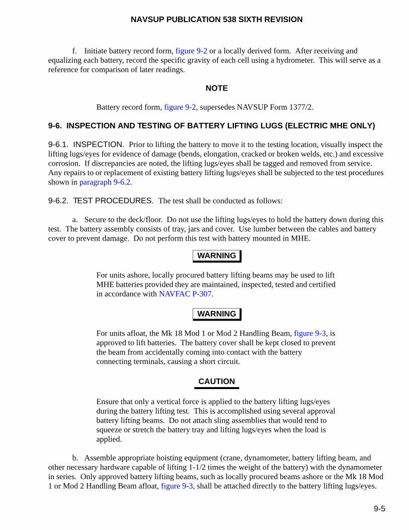
NAVSUP PUBLICATION 538 SIXTH REVISION
9-5
f. Initiate battery record form, figure 9-2 or a locally derived form. After receiving and equalizing each battery, record the specific gravity of each cell using a hydrometer. This will serve as a reference for comparison of later readings.
NOTE
Battery record form, figure 9-2, supersedes NAVSUP Form 1377/2.
9-6. INSPECTION AND TESTING OF BATTERY LIFTING LUGS (ELECTRIC MHE ONLY)
9-6.1. INSPECTION. Prior to lifting the battery to move it to the testing location, visually inspect the lifting lugs/eyes for evidence of damage (bends, elongation, cracked or broken welds, etc.) and excessive corrosion. If discrepancies are noted, the lifting lugs/eyes shall be tagged and removed from service. Any repairs to or replacement of existing battery lifting lugs/eyes shall be subjected to the test procedures shown in paragraph 9-6.2.
9-6.2. TEST PROCEDURES. The test shall be conducted as follows:
a. Secure to the deck/floor. Do not use the lifting lugs/eyes to hold the battery down during this test. The battery assembly consists of tray, jars and cover. Use lumber between the cables and battery cover to prevent damage. Do not perform this test with battery mounted in MHE.
For units ashore, locally procured battery lifting beams may be used to lift MHE batteries provided they are maintained, inspected, tested and certified in accordance with NAVFAC P-307.
For units afloat, the Mk 18 Mod 1 or Mod 2 Handling Beam, figure 9-3, is approved to lift batteries. The battery cover shall be kept closed to prevent the beam from accidentally coming into contact with the battery connecting terminals, causing a short circuit.
Ensure that only a vertical force is applied to the battery lifting lugs/eyes during the battery lifting test. This is accomplished using several approval battery lifting beams. Do not attach sling assemblies that would tend to squeeze or stretch the battery tray and lifting lugs/eyes when the load is applied.
b. Assemble appropriate hoisting equipment (crane, dynamometer, battery lifting beam, and other necessary hardware capable of lifting 1-1/2 times the weight of the battery) with the dynamometer in series. Only approved battery lifting beams, such as locally procured beams ashore or the Mk 18 Mod 1 or Mod 2 Handling Beam afloat, figure 9-3, shall be attached directly to the battery lifting lugs/eyes.
WARNING
WARNING
CAUTION
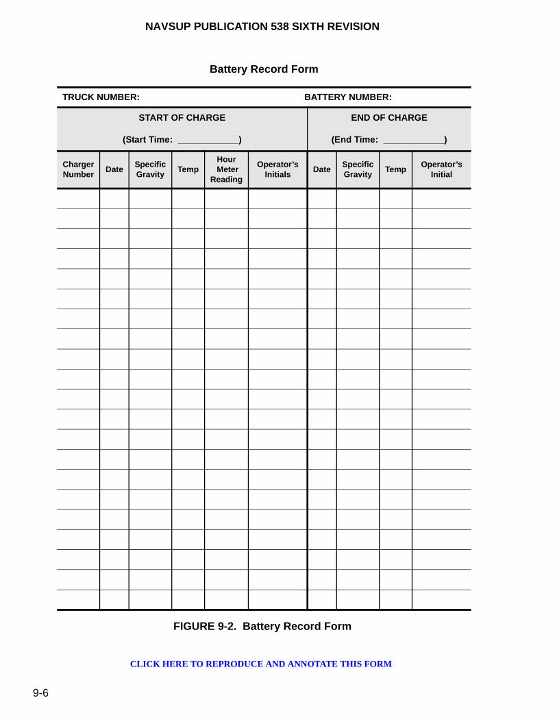
NAVSUP PUBLICATION 538 SIXTH REVISION
9-6
FIGURE 9-2. Battery Record Form
Battery Record Form
TRUCK NUMBER: BATTERY NUMBER:
START OF CHARGE END OF CHARGE
(Start Time: ____________) (End Time: ____________)
ChargerNumber
DateSpecificGravity
TempHour
MeterReading
Operator’sInitials
DateSpecificGravity
TempOperator’s
Initial
CLICK HERE TO REPRODUCE AND ANNOTATE THIS FORM

NAVSUP PUBLICATION 538 SIXTH REVISION
9-7
c. Hoist the battery by its lifting lugs until the dynamometer registers 1-1/2 times the gross weight of the battery assembly.
d. Hold the force for two minutes.
e. Lower the battery and remove the lifting equipment.
FIGURE 9-3. Mk 18 Mod 1 or Mod 2 Handling Beam
9-6.3. TEST RESULTS. Examine the lifting lugs/eyes and points where attached to the battery. The battery shall be rejected if the battery lifting lugs/eyes exhibit elongation, permanent deformation, fractures or other evidence of failure. Any cracks or fractures in the welds that attach the lugs/eyes to the battery tray housing are also cause for rejection.
9-7. BATTERY INSTALLATION
a. Ensure the battery compartment is clean and free of any water, oil, dirt, and other foreign matter. If the battery compartment appears wet where there is no obvious source of moisture, then the dampness is probably sulfuric acid from spilled electrolyte. Sulfuric acid does not evaporate as does water and will need to be cleaned to avoid corrosion of the battery compartment. Neutralize and clean spilled electrolyte in accordance with paragraph 9-15.
b. Ensure the battery compartment has drainage holes located in the floor. Remove any foreign matter that may be clogging the holes.
NAVSUP PUBLICATION 538 SIXTH REVISION
9-8
c. Visually inspect the battery lifting lugs/eyes for evidence of damage (bends, elongation, cracked or broken welds, etc.) and excessive corrosion. If any such discrepancies are noted, repairs shall be made before proceeding with this test.
Only use authorized battery lifting equipment to hoist lead-acid batteries and to connect to the battery lifting lugs. Do not use sling assemblies that would tend to squeeze or stretch the battery tray and lifting lugs as the load is applied. The Mk 18 Mod 1 or Mod 2 Handling Beam, figure 9-3, is approved for lifting batteries afloat, while locally procured lifting beams are approved ashore.
Do not use the Mk 18 Mod 1 or Mod 2 Handling Beam with batteries without lift tabs or those that do not allow full contact with the lift hook throat.
d. Attach a Mk 18 Mod 1 or Mod 2 Handling Beam (afloat), figure 9-3, or a locally procured beam (ashore) to the battery lift eyes/lugs. Position a conveyor, overhead hoist, or other hoisting machine directly above the battery. Lower hoisting machine and connect to battery lifting beam. An intermediate device installed between the hoisting device and the battery beam is permitted so long as the safe working load (SWL) is not exceeded. When an authorized/approved battery lifting device is not available and fleet commitments dictate that a battery must be removed or replaced, an alternate lifting device may be used to lift the battery. This alternate device may be used only after interim approval has been granted by the Naval Surface Warfare Center (NAVSURFWARCEN), Indian Head Division Detachment Picatinny, Naval PHST Center (Code G1) and the following requirements are met:
(1) During lifting, the battery cover is kept closed. If this is not possible or if the cover is missing, all lead cell connectors must be covered with an insulating material, such as plywood or thick rubber.
(2) The lifting device applies a vertical force only on the battery lifting lugs/eyes. Slings which tend to stretch or squeeze the battery tray as vertical force is applied are not approved.
(3) The lifting device has two hooks which are electrically insulated from each other to prevent short circuits.
e. Hoist battery, remove it from storage area, and install into MHE.
f. Battery shall be properly positioned and secured in the MHE. Battery should be blocked, not wedged, to allow for 1/8-inch minimum clearance on all sides for easy removal from the battery compartment. Also some batteries tend to expand or contract during service, so wedging them into the battery compartment could result in damage.
WARNING
WARNING
NAVSUP PUBLICATION 538 SIXTH REVISION
9-9
g. During storage, a battery may lose some of its charge. Prior to using the battery, inspect the battery record. If the battery record, figure 9-2, indicates that the battery has been out of service or has been in storage for over five days, perform an equalizing charge as described in paragraph 9-9 or an extended charge as described in paragraph 9-10 depending on the type of charger.
When cleaning battery connections, verify the lead coating is not removed from terminals, exposing copper.
h. Ensure all connections on the battery are clean and free of debris.
i. Connect the battery to MHE. Ensure all the connections are tight. Due to vibration, handling and temperature change, all bolted connections will loosen during normal operation. All bolted connections should be inspected and tightened in accordance with the applicable MRC.
j. Once the battery installation is complete, coat all bolted connections and terminals with Grease, Aircraft and Instruments, MIL-PRF-23827. Battery Protector and Sealer, Part No. SA-9 (Permatex) is an approved alternate corrosion preventive compound.
9-8. BATTERY CHARGING, TESTING, AND MAINTENANCE
Battery charging shall be performed in accordance with the applicable manufacturer’s technical instructions (ashore) or applicable MRC’s (afloat) to maximize both the single charge operating time of the battery and the long-term capability of the battery to consistently attain the maximum charge. Local operating procedures are required ashore and afloat and shall be posted on or near the battery charger. Procedures for the testing and maintenance of batteries are provided later in this chapter.
NOTE
The length of charging times and temperature requirements identified in this chapter are written to maintain the optimum life and serviceability of the battery. They do not consider fleet operational or high use operations beyond the prescribed limits. Be aware that continued operation beyond these specified limits will greatly reduce the service life of the battery.
9-8.1. LOCATION. At least one area shall be specifically designated, with the proper requirements, for the charging, testing and maintenance of lead-acid batteries in powered MHE. Battery charging, testing and maintenance shall only be done in those areas designated specifically for that purpose. Battery charging, testing and maintenance shall not be performed in magazines or other areas/spaces where ammunition and explosives are present. MHE shall be properly positioned on a level surface with brakes applied before batteries are charged or replaced.
9-8.1.1. Ashore. In addition to the requirements of paragraph 9-8.1, the following shall apply ashore:
a. Battery charging, testing and maintenance shall comply with OPNAVINST 5100.23 (series) and 29 CFR 1910.132.
CAUTION

NAVSUP PUBLICATION 538 SIXTH REVISION
9-10
b. When charging stations are in proximity to ammunition and explosives operations, the provisions of NAVSEA OP 5 shall be met and operating procedures posted accordingly.
9-8.1.2. Afloat. In addition to the requirements in paragraph 9-8.1, units afloat shall refer to NAVSEA OP 4 for other regulations concerning battery charging stations.
9-8.2. FIRE SAFETY REGULATIONS. Fire extinguishing equipment shall be installed and maintained in all battery charging areas in accordance with the local fire bill. Extinguishers installed on MHE can satisfy this requirement. The type of extinguisher required, location, training requirements for emergency use and other pertinent safety information afloat and ashore shall be contained in local procedures covering MHE operations. Table A-2-1 in the National Fire Protection Association (NFPA) 10 contains guidance in selecting the type of extinguisher required for a specific fire hazard.
9-8.3. BATTERY CHARGING SAFETY PRECAUTIONS. The following precautions shall be observed prior to the charging of batteries:
Severe burns can be caused by the sulfuric acid contained in batteries. In case of contact, thoroughly flush affected area with clean water. Obtain medical attention immediately.
a. In the event that electrolyte should spill, cease all operations, notify personnel in the area, and begin emergency clean up/containment in accordance with local procedures.
b. Fire protection apparatus shall be provided.
c. Charging apparatus shall be protected from physical damage by MHE.
d. Adequate ventilation must be provided for the dispersal of fumes from gassing batteries.
e. An emergency shower/eyewash fountain shall be available, as required by OPNAVINST 5100.23 (series), and must be accessible at all times.
f. Use safe and effective devices such as a tilter siphon or pump when handling electrolyte.
g. Use of personal protective equipment shall be based on the industrial hygiene survey, as stated in OPNAVINST 5100.23 (series) (ashore) or OPNAVINST 5100.19 (series) (afloat), and the hazard assessment conducted by the activity or ship, as stated in 29 CFR 1910.132.
h. If battery and battery charging unit are in separate locations, then two people are required to make the connections/disconnections. Visual or audio communication is required to ensure the safety of these individuals.
i. Observe all “NO SMOKING” regulations. Smoking or other extraneous sources of ignition shall be prohibited in battery charging areas.
WARNING
NAVSUP PUBLICATION 538 SIXTH REVISION
9-11
j. Personnel shall remove all jewelry (rings, watches, etc.) prior to servicing batteries.
k. Do not attempt to charge a battery with loose, damaged or corroded terminals, which may result in causing excess heat, arcing or an explosion.
l. Verify the battery is in the OFF position before connecting or disconnecting batteries.
m. Battery lockers shall only be used for battery charging and battery stowage, and must be readily accessible by personnel.
n. Prior to connecting the electric battery to the battery charging system, inspect both connectors for any damage or corrosion. Inspect all cables for damage, cuts and abrasions. Verify that the cables securely fasten to connector logs and are free of corrosion, verdigris, arcing, pitting, exposed conductor material, or loose connections.
An explosion can result from the hydrogen gas produced from battery charging.
Severe burns can be caused by the sulfuric acid contained in batteries. In case of contact, thoroughly flush affected area with clean water. Obtain medical attention immediately.
When mixing electrolyte, acid shall be poured into water, not water into acid.
Lead-acid batteries shall only be charged by trained and authorized personnel.
9-8.4. BATTERY CHARGING PROCEDURAL REQUIREMENTS. In addition to observing the safety precautions outlined in paragraph 9-8.3, the following general procedural requirements shall be applied during the actual charging of batteries:
a. If a battery is to be charged while still installed in the MHE, ensure that it is electrically disconnected from the MHE.
b. Charge batteries immediately after discharging (providing cell temperature is less that stated below).
WARNING
WARNING
WARNING
CAUTION

NAVSUP PUBLICATION 538 SIXTH REVISION
9-12
c. If a battery has just been removed from service, allow the battery to cool to an internal temperature of 90 °F or less before commencing charging operations.
d. Open battery’s compartment cover to increase ventilation. This will accelerate the pre-charge cooling process. It shall remain open throughout the charging process.
e. Ensure the top of the battery is clean, dry and free of any materials that could cause ground shorts during charging.
f. Ensure all battery vent plugs are present and firmly in place. Vent plugs shall only be removed to add water, and to take hydrometer/refractometer and temperature readings. Ensure vent caps are not clogged by washing them periodically with water and blowing through the bottom with low pressure air.
g. Connect battery to charging apparatus and commence charging in accordance with paragraph 9-8.6.
To avoid damaging the battery, never allow the electrolyte temperature to exceed 115 °F during charging. Reduce or stop current if electrolyte reaches this temperature.
Do not continuously exceed a battery beyond 80 percent discharge. Its service life will be greatly diminished.
h. Ensure that the battery receives the proper amount of current and voltage throughout the charging process. This will vary depending on the temperature of the electrolyte inside the battery and to what degree the battery has been discharged. It will also vary among batteries from different manufacturers. Automatic battery chargers will usually make the correct voltage/current adjustments on their own, but it is important that the battery is hooked up to an automatic charger compatible with that battery make and model. Where automatic equipment is not available, charging personnel will have to make these adjustments manually. Generally speaking, lead-acid batteries can be charged at any rate of current that does not cause excessive gassing or produce temperatures in excess of 115 °F. But as the battery approaches full charge, the current will need to be gradually reduced to the finish rate. Knowing when a battery is approaching full charge requires periodic readings of the electrolyte's specific gravity. If a battery is to deliver optimum performance and long life, it should be sized to deliver a full shift of work, while discharging to not more than 80 percent of the total rated capacity. Normally, the specific gravity for fully charged batteries range from 1.285 to 1.315 (± 0.005). Refer to the specific battery manufacturer’s battery instruction manual for actual specific gravities. The actual specific gravity (at 100 percent charge) and the voltage for a particular battery will be located on the battery plate or stamped into the top of the battery case. The voltage will also be located on the MHE identification plate.
i. When it is determined that the battery is fully charged, turn off and disconnect battery from charging equipment.
CAUTION
CAUTION

NAVSUP PUBLICATION 538 SIXTH REVISION
9-13
j. Depending on the type of battery charger, when necessary, perform either an equalizing charge in accordance with paragraph 9-9 or an extended charge (for most ships) in accordance with paragraph 9-10.
k. Lead-acid batteries shall not be charged more than once in a 24-hour period.
NOTE
Consistent undercharge results in excess sulfation and gradual reduction of battery life. Overcharge will result in excess gassing, low water levels, and damage to battery.
9-8.5. BATTERY MAINTAINER - HELPFUL TIPS. The following are helpful informational tips for personnel responsible for maintaining batteries:
a. If possible, keep battery temperatures below 77 °F to achieve the longest battery life. Batteries operating at 100 °F will only last half as long as a battery operating at 77 °F.
b. Serviceable batteries normally will be within 8 to 10 points from its original specific gravity reading. For example, when new, a battery’s specific gravity will be 1.290. It will gradually be reduced to a specific gravity of 1.282 after repeated cycling. This is normal and indicates that a battery has been cycled, but is otherwise fully functional.
c. Never add acid to a battery cell. This does not take into account the loss of electrolyte due to accident or overfill spillage.
d. Use only distilled water when filling batteries.
e. Never allow a battery to remain discharged for long periods.
f. Unless a low level is detected, do not add distilled water to a battery prior to placing on charge.
g. When adding distilled water to a fully charged battery, fill the cells to within 1/8 to 1/4 inches from the bottom of the vent well tube as shown in figure 9-1.
Automatic battery filler has an adjustable nozzle that allows a precise shut off capability for watering batteries and must be properly adjusted when received to avoid overfilling.
h. Batteries discharged greater than 80 percent capacity will require recharge times in excess of 8 hours. Continued battery discharging greater than 80 percent of the battery’s capacity will result in a reduce life and cell damage.
CAUTION

NAVSUP PUBLICATION 538 SIXTH REVISION
9-14
i. Battery cells with specific gravities of 1.240 and below should be placed on either an equalizing charge (paragraph 9-9) or an extended charge (paragraph 9-10) depending on the type of charger for the recommended time to maintain full readiness capability.
j. Battery cells with specific gravities greater than 1.240 but less than full charge should be placed on either an equalizing charge (paragraph 9-9) or an extended charge (paragraph 9-10) depending on the type of charger once every week.
k. One complete battery cycle is a discharge to 80 percent with a subsequent recharge to full capacity. A discharge to 40 percent capacity with subsequent recharge is considered half a battery cycle. The average forklift truck battery life is 1,500 cycles.
l. Causes for low specific gravity readings are:
(1) The battery is old or nearing the end of its life cycle.
(2) The battery was left in a discharged state for too long.
(3) Electrolyte was lost due to spillage.
(4) A weak or bad cell is developing.
(5) The battery was over-watered prior to testing.
(6) The battery did not receive a complete charge.
(7) The battery charger is not functioning correctly.
m. Causes for excessive water use are:
(1) The battery was left on charge or extended charge too long.
(2) The battery temperature is too high at the beginning or at the end of charge.
(3) The battery is nearing the end of usable life.
9-8.6. BATTERY CHARGING PROCEDURES. After observing the safety precautions addressed in paragraph 9-8.3 and the procedural requirements identified in paragraph 9-8.4, this paragraph describes the actual charging procedures that shall be undertaken whenever a lead-acid battery’s specific gravity falls below 1.240. Table 9-1 lists the required tools, materials and test equipment in support of safely charging these batteries. It also contains the applicable Standard PMS Item Name (SPIN) and National Stock Number (NSN).
Do not use these procedures for gel or absorbed glass mat type batteries.
CAUTION

NAVSUP PUBLICATION 538 SIXTH REVISION
9-15
a. Set the parking brake and remove the ignition key.
b. If equipped, turn the master battery disconnect switch to the OFF position.
c. Attach a “DO NOT OPERATE” tag (figure 8-6) on the MHE.
d. Disconnect the battery power cables at the connectors.
e. Loosen and remove the retaining bolts of the battery cover and raise cover.
Do not disconnect the battery by pulling on the cable.
f. Grasp the receptacle and disconnect the battery connector. Visually ensure the contacts are clean, bright (no carbon, grease, dirt, etc.) and flat. If contacts are dirty or pitted, proceed with paragraph g. If contacts are acceptable, proceed with paragraph h.
g. With a crocus (abrasive) cloth and using light pressure, polish the contact surfaces. Using a clean rag lightly moistened with a cleaning solvent and remove any residue from the contact surfaces.
NOTE
Do not substitute sandpaper or steel wool for crocus cloth.
h. Open the battery box cover and remove the battery fill/vent caps.
NOTE
Battery cover will remain open or slightly open during charging to prevent the pooling of explosive hydrogen gases.
i. Inspect battery cables for loose, damaged or corroded terminal posts, damage to the cable insulation, and clogging or debris of the battery vent/top. Clean or repair terminals and insulation, as required. Clean the vent/fill caps, as required, by submerging in water. Then using low-pressure air, blow out any debris from the underside of the cap.
NOTE
When taking the specific gravity and temperature readings of the cells, a hydrometer or a refractometer are two acceptable pieces of test equipment. Follow paragraph j procedures when using a hydrometer or follow paragraph k when using a refractometer. Then continue with paragraph l.
CAUTION
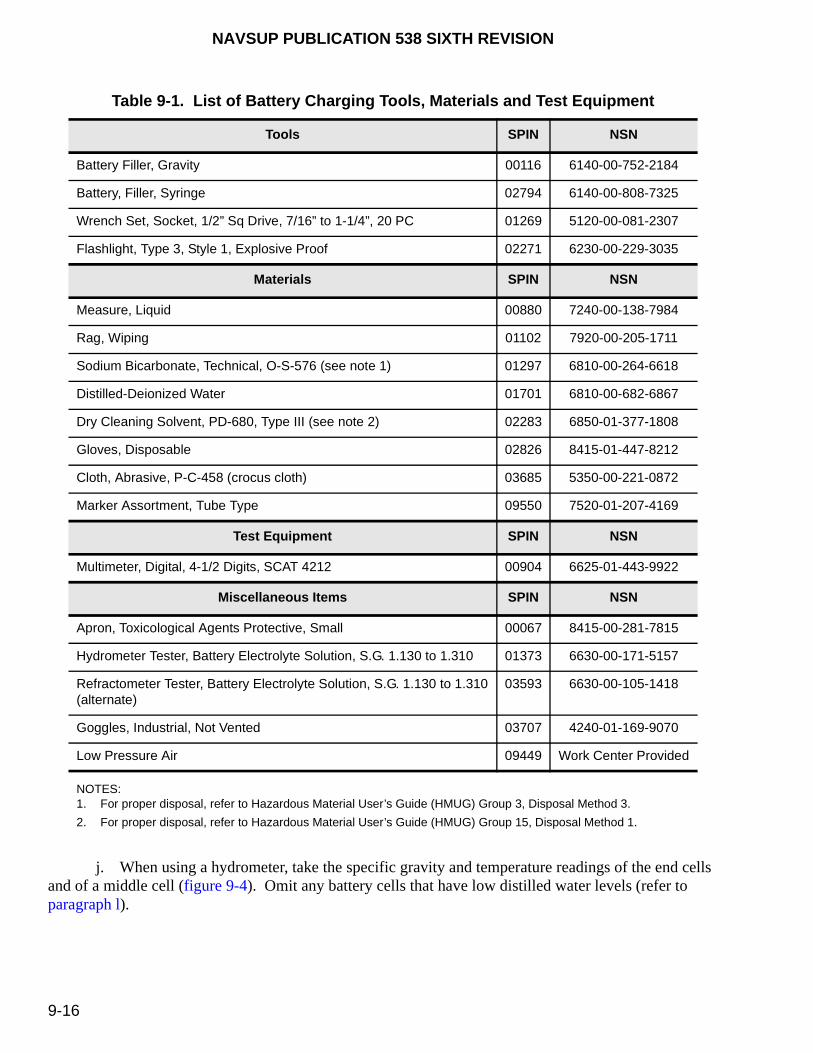
NAVSUP PUBLICATION 538 SIXTH REVISION
9-16
j. When using a hydrometer, take the specific gravity and temperature readings of the end cells and of a middle cell (figure 9-4). Omit any battery cells that have low distilled water levels (refer to paragraph l).
Table 9-1. List of Battery Charging Tools, Materials and Test Equipment
Tools SPIN NSN
Battery Filler, Gravity 00116 6140-00-752-2184
Battery, Filler, Syringe 02794 6140-00-808-7325
Wrench Set, Socket, 1/2” Sq Drive, 7/16” to 1-1/4”, 20 PC 01269 5120-00-081-2307
Flashlight, Type 3, Style 1, Explosive Proof 02271 6230-00-229-3035
Materials SPIN NSN
Measure, Liquid 00880 7240-00-138-7984
Rag, Wiping 01102 7920-00-205-1711
Sodium Bicarbonate, Technical, O-S-576 (see note 1) 01297 6810-00-264-6618
Distilled-Deionized Water 01701 6810-00-682-6867
Dry Cleaning Solvent, PD-680, Type III (see note 2) 02283 6850-01-377-1808
Gloves, Disposable 02826 8415-01-447-8212
Cloth, Abrasive, P-C-458 (crocus cloth) 03685 5350-00-221-0872
Marker Assortment, Tube Type 09550 7520-01-207-4169
Test Equipment SPIN NSN
Multimeter, Digital, 4-1/2 Digits, SCAT 4212 00904 6625-01-443-9922
Miscellaneous Items SPIN NSN
Apron, Toxicological Agents Protective, Small 00067 8415-00-281-7815
Hydrometer Tester, Battery Electrolyte Solution, S.G. 1.130 to 1.310 01373 6630-00-171-5157
Refractometer Tester, Battery Electrolyte Solution, S.G. 1.130 to 1.310(alternate)
03593 6630-00-105-1418
Goggles, Industrial, Not Vented 03707 4240-01-169-9070
Low Pressure Air 09449 Work Center Provided
NOTES:1. For proper disposal, refer to Hazardous Material User’s Guide (HMUG) Group 3, Disposal Method 3.
2. For proper disposal, refer to Hazardous Material User’s Guide (HMUG) Group 15, Disposal Method 1.

NAVSUP PUBLICATION 538 SIXTH REVISION
9-17
NOTE
Testing just the positive and negative end cells (where the cable originates) and a middle cell can be used as an indicator of the overall condition of the battery.
NOTE
Ensure electrolyte tester is clean to prevent erroneous readings.
(1) Draw electrolyte into hydrometer until the float is suspended freely and is free of air bubbles (figure 9-4).
(2) Read the scale on the hydrometer stem, where the upper portion of the electrolyte makes contact. Void the electrolyte into the same cell. Annotate the readings for reference. Continue for both end cells and for a middle cell.
FIGURE 9-4. Reading the Hydrometer
NOTE
The actual specific gravity (at 100 percent charge) and voltage for a particular battery will be located on the battery plate or stamped into the top of the battery case. The voltage will also be located on the identification plate of the MHE [voltage may be determined by counting the number of battery cells (fill caps) and multiplying that number by 2]. Depending on the battery manufacturer, the specific gravity of a fully charged battery varies between 1.285 to 1.315.
NAVSUP PUBLICATION 538 SIXTH REVISION
9-18
(3) Verify the temperature indicated on the thermometer. Readings below 1.240 corrected to 77 °F (refer to table 9-1) shall be charged as follows:
NOTE
As a general rule for electrolyte temperature correction, for every 10 degrees above 77 °F, add three points to the specific gravity (e.g., 1.240 at 87 °F is actually 1.243). Conversely, for every 10 degrees below 77 °F, subtract 3 points from the specific gravity. This method applies to the temperature of the electrolyte and not ambient air temperature.
k. When using a refractometer, take the specific gravity and temperature readings of the end cells and of a middle cell. Omit any battery cells that have low distilled water levels (refer to paragraph l).
Do not use the plastic coolant tester tube when sampling battery electrolyte, which may damage the instrument.
(1) Remove the dipstick located on the tester, dip it into the battery cell while under test, and place a few drops on the measuring prism. Close the sample cover pointing the tester toward a light source and read the battery scale.
(2) Swing back the plastic sample cover located at the slanted end of the instrument to expose the measuring prism and wipe both clean using a clean, soft cloth.
(3) Repeat paragraph (1) and (2) above for each cell under test.
(4) Clean and dry measuring prism and sample cover using distilled water and a soft, clean cloth between each use and before returning to storage.
Do not overfill cells with distilled water because levels will rise during charging spilling the electrolyte. For battery cells with low levels, use the battery filler syringe only and not the automatic (2 quart) battery filler for filling to prevent overfilling prior to charging.
l. Check all cells for low water levels. Add only enough distilled water to just cover the cell plates/protector (see figure 9-1). Do not overfill.
m. Replace battery fill/vent caps.
CAUTION
CAUTION

NAVSUP PUBLICATION 538 SIXTH REVISION
9-19
NOTE
The temperatures and charging times prescribed in these maintenance procedures are provided to maintain the battery’s optimum life and serviceability. They do not take into consideration fleet operational or high use requirements that may demand operations outside of this range, which will reduce the battery’s service life.
Verify the battery charger is in the OFF position before connecting or disconnecting batteries.
Operational requirements may dictate temperatures exceeding 90 °F during charging. Do not allow battery temperatures to exceed 115 °F during charging, which will reduce its service life. Allow as much “cooling off” time as operationally possible before and after battery charging.
n. Verify that all charger indicators are not illuminated and connect the battery charger to the battery.
o. Select the correct amperage on the charger for the battery under charge and select the correct voltage (if so equipped, Type IV charger).
NOTE
Batteries used in the Raymond Corp. reach and tier forklift trucks are all 24 volts and use the 210 amp charger setting, if equipped with adjustable settings.
Fluctuating dial readings, readings that are full scale, smoke or violent gassing may indicate a shorted battery cell or incorrect connection. Turn the charger immediately to the OFF position and recheck the connections and settings.
WARNING
CAUTION
WARNING

NA
VS
UP
PU
BL
ICA
TIO
N 53
8 SIX
TH
RE
VIS
ION
9-20
FIGURE 9-5. Battery Discharge Charts

NAVSUP PUBLICATION 538 SIXTH REVISION
9-21
p. Turn the charger to the ON position and monitor the voltage and amperage gauges, which should indicate a steady value.
NOTE
Shipboard battery chargers are calibrated to take a battery that has been discharged 80 percent and bring to a full charge in 8 hours. Batteries may be left on charge longer than 8 hours without battery damage, due to the charger design to reduce hydrogen gas generation in poorly vented spaces. The battery will not become excessively overcharged, but electrolyte levels must be monitored. Allow a maximum cool-down time between charging and use, especially in hot environments.
q. Use the initial battery’s specific gravity reading and compare it to the applicable specific gravity charts in figure 9-5 for that particular cell type to determine the approximate amount of battery discharge. (Example: If the initial battery reading is 1.210 and using figure 9-5 for a battery with a specific gravity of 1.315, then the 1.210 specific gravity intersects the discharge line at approximately 50 percent discharge state. Since the battery is not discharged to 80 percent, it would not require the full 8-hour charge.)
NOTE
When determining the charge time for a battery, refer to figure 9-5 and estimate the recharge time by rounding up to the nearest 1/2 to 1 hour.
r. When operational requirements permit, take the specific gravity readings and temperature for all cells prior to shutting off the charger to ensure a full charge. Inspect the cell for low electrolyte levels. If the battery is fully charged, add distilled water to 1/8 to 1/4 inch from the bottom of the vent wall opening (figure 9-1). If the readings are not up to full charge, continue charging based on the specific gravity using figure 9-5. (Example: If the battery’s specific gravity is 1.260 and using figure 9-5 for batteries with a specific gravity of 1.315, then the battery is still approximately 25 percent discharged.) When placing it back on charge, ensure the electrolyte levels for all cells are above the battery separator/plates.
NOTE
Batteries or cells that do not rise above the specific gravity of 1.260, even with continued charging, should have the end of life cycle testing performed in accordance with paragraph 9-11.
NOTE
Do not add distilled water to a battery cell that is not at full charge, unless a low level is indicated, as the cell is not finished charging and the acid will continue to be expelled from the positive plate.

NAVSUP PUBLICATION 538 SIXTH REVISION
9-22
s. Batteries that are fully charged, but have low electrolyte levels, shall have distilled water added to the maximum level (1/8 to 1/4 inch below the bottom of the fill tube as shown in figure 9-1) and allowed to charge for an additional 1 hour to allow the distilled water to mix prior to shutting down the charger. Ensure to inspect a middle battery cell for acceptable temperature readings (less than 115 °F) before continuing further charging.
t. Secure the battery fill/vent caps.
NOTE
Do not return a battery for use with an internal temperature of more than 90 °F. Allow for it to cool down, unless operational or mission need dictate its continued use.
Ensure the battery vent/fill caps are in place before using acid neutralizing solution to prevent damage to the cells.
u. Wipe any moisture or electrolyte residue from the top of the battery using a clean rag dampened with neutralizing solution, followed by drying it with a clean rag. To make acid neutralization solution, add 1 pound of bicarbonate soda to 1 gallon of distilled water then mix thoroughly.
v. Close the battery cover and secure hold-down bolts.
w. Connect the battery connector cables to the forklift truck and return it to readiness condition.
9-9. EQUALIZING CHARGE
An equalizing charge can be accomplished by all shore activities and only a few of the newly constructed (CVN or amphibious) ships. Ships that do not have this capability shall perform an extended charge in accordance with paragraph 9-10.
9-9.1. BACKGROUND. Each cell of a battery has slight differences in uniformity of construction and content. These slight differences causes some cells to require slightly more charging time than others do to reach a fully charged state. If this fact were simply ignored, certain cells in a given battery would always receive slightly less than a full 100 percent charge. Over time, these cells would gradually succumb to effects of chronic undercharging, which is sulfation, and drift back in capacity. To ensure that these battery cells are occasionally brought to a full state of charge, the battery is given additional charging time beyond what is normally required to fully charge the battery. This is called equalizing. Since it is not possible to apply charging current to individual cells, the other cells in the battery may be overcharged somewhat. This is acceptable as long as their temperatures do not exceed 115 °F. A decrease in electrolyte level due to increased gassing is the only concern. Therefore, electrolyte levels should be monitored carefully during and after equalizing charges. Consult the battery manufacturer's instructions for how much current to use during equalizing. Typically, an equalize cycle continues the charge for an additional 3 hours following a normal charge.
CAUTION
NAVSUP PUBLICATION 538 SIXTH REVISION
9-23
NOTE
The length of charging times and temperature requirements identified in this chapter are written to maintain the optimum life and serviceability of the battery. They do not consider fleet operational or high use operations beyond the prescribed limits. Be aware that continued operation beyond these specified limits will greatly reduce the service life of the battery.
9-9.1.1. Shore Activity Chargers. Shore activities employ commercial automatic chargers that incorporate the constant current-constant voltage-constant current (IEI curve) techniques for recharging electric batteries. These fully, automated charging systems are capable of performing equalizing charges prescribed in this paragraph.
9-9.1.2. Shipboard Chargers.
a. Current Systems. Electric battery chargers used aboard ship are qualified in accordance with DOD-C-24529, which is obsolescent. They employ a constant current to constant voltage curve with a tapering current. These type of battery chargers cannot perform the traditional equalizing charge with an extended constant current period beyond the normal finishing rate like shore activity chargers. Instead, they are capable of prolonged float at low current and at a non-adjustable voltage limit of 2.33 to 2.37 volts per cell as described in paragraph 9-10.
b. Future Systems. The forthcoming new electric battery chargers used aboard ship are qualified in accordance with CID A-A-59814. They are capable of charging both flooded lead-acid and maintenance free batteries. Contact your TYCOM MHE Manager or local FICP for more information regarding these new battery chargers.
9-9.2. EQUALIZING FREQUENCY. Equalizing charges need not be performed every single time a battery is recharged. The frequency depends on how often the battery is cycled and to what depth it is being discharged. Battery manufacturers' instructions are the best source of information as to how often a battery should be equalized. Generally speaking:
a. Batteries that are cycled only once or twice a week to an average depth of 30 to 60 percent, need equalizing charges only once per month.
b. Batteries that are cycled four to eight times per month to any depth require equalizing once per month.
c. Batteries that are cycled three or more times per week to an average depth of 60 to 80 percent should be equalized weekly.
d. Batteries that are cycled five or more times a week to an average depth of 60 percent or greater usually never require equalizing unless stored.
9-9.3. DETERMINING DEPTH OF DISCHARGE. Depth of discharge can be determined by measuring the specific gravity of the electrolyte. This is accomplished using a hydrometer. Specific gravity decreases as the battery becomes more discharged. Depending on the type of battery cells, the
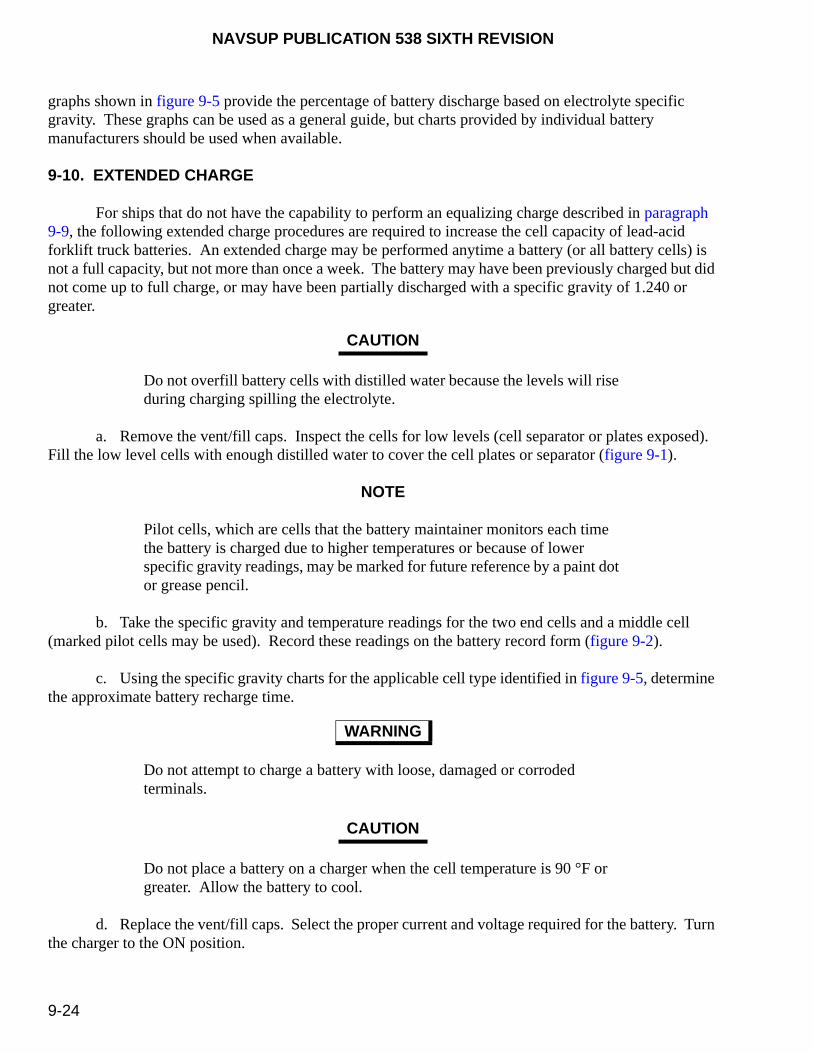
NAVSUP PUBLICATION 538 SIXTH REVISION
9-24
graphs shown in figure 9-5 provide the percentage of battery discharge based on electrolyte specific gravity. These graphs can be used as a general guide, but charts provided by individual battery manufacturers should be used when available.
9-10. EXTENDED CHARGE
For ships that do not have the capability to perform an equalizing charge described in paragraph 9-9, the following extended charge procedures are required to increase the cell capacity of lead-acid forklift truck batteries. An extended charge may be performed anytime a battery (or all battery cells) is not a full capacity, but not more than once a week. The battery may have been previously charged but did not come up to full charge, or may have been partially discharged with a specific gravity of 1.240 or greater.
Do not overfill battery cells with distilled water because the levels will rise during charging spilling the electrolyte.
a. Remove the vent/fill caps. Inspect the cells for low levels (cell separator or plates exposed). Fill the low level cells with enough distilled water to cover the cell plates or separator (figure 9-1).
NOTE
Pilot cells, which are cells that the battery maintainer monitors each time the battery is charged due to higher temperatures or because of lower specific gravity readings, may be marked for future reference by a paint dot or grease pencil.
b. Take the specific gravity and temperature readings for the two end cells and a middle cell (marked pilot cells may be used). Record these readings on the battery record form (figure 9-2).
c. Using the specific gravity charts for the applicable cell type identified in figure 9-5, determine the approximate battery recharge time.
Do not attempt to charge a battery with loose, damaged or corroded terminals.
Do not place a battery on a charger when the cell temperature is 90 °F or greater. Allow the battery to cool.
d. Replace the vent/fill caps. Select the proper current and voltage required for the battery. Turn the charger to the ON position.
CAUTION
WARNING
CAUTION

NAVSUP PUBLICATION 538 SIXTH REVISION
9-25
NOTE
Damaged or battery cells at the end of their life may not be capable of reaching 100 percent charge or the required specific gravity. Refer to the end of life cycle testing requirements (paragraph 9-11) to schedule for repairing or replacing batteries.
e. At the conclusion of the specified recharge time, take the specific gravity readings for the three marked cells (pilot or ends and middle cells). If the specific gravity has increased, but is still not at 100 percent charge, continue charging the battery for an additional 3 hours or until the specific gravity no longer increases any further. If the temperature reaches 115 °F, then the battery should be allowed to cool prior to continuing.
NOTE
The battery record form, figure 9-2, may be used for tracking the battery’s longevity and system performance (charger, battery condition and maintenance). Locally derived forms or electronic tracking methods may be used, provided they meet the minimum requirements of the battery record form, figure 9-2.
f. When the specific gravity readings no longer increase while being charged, take a final specific gravity and temperature reading, record them in the battery record form, figure 9-2, or equivalent for future reference. Figure 9-6 identifies the correct battery cell sequence for recording purposes.
NOTE
Numbering sequence for battery cells in series starting at the positive battery terminal.
NOTE
If used semi-annually for new batteries or quarterly for in-service batteries, the battery record form, figure 9-2, will assist the battery maintainer and mechanic prevent equipment downtime and will assist in maintaining full operational equipment capability.
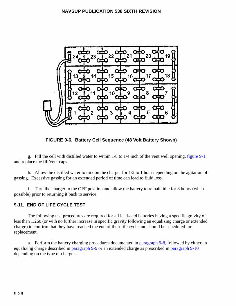
NAVSUP PUBLICATION 538 SIXTH REVISION
9-26
FIGURE 9-6. Battery Cell Sequence (48 Volt Battery Shown)
g. Fill the cell with distilled water to within 1/8 to 1/4 inch of the vent well opening, figure 9-1, and replace the fill/vent caps.
h. Allow the distilled water to mix on the charger for 1/2 to 1 hour depending on the agitation of gassing. Excessive gassing for an extended period of time can lead to fluid loss.
i. Turn the charger to the OFF position and allow the battery to remain idle for 8 hours (when possible) prior to returning it back to service.
9-11. END OF LIFE CYCLE TEST
The following test procedures are required for all lead-acid batteries having a specific gravity of less than 1.260 (or with no further increase in specific gravity following an equalizing charge or extended charge) to confirm that they have reached the end of their life cycle and should be scheduled for replacement.
a. Perform the battery charging procedures documented in paragraph 9-8, followed by either an equalizing charge described in paragraph 9-9 or an extended charge as prescribed in paragraph 9-10 depending on the type of charger.

NAVSUP PUBLICATION 538 SIXTH REVISION
9-27
b. Allow the battery to rest, open circuit (but do not connect the battery coupler to the forklift truck even with all power off) for a minimum of 8 hours.
Do not short meter probes across the battery connector terminals to prevent damage to the meter.
c. Using a multimeter, measure the voltage at the battery connectors. Based on 2.08 volts in each cell, batteries that do not meet the below minimum volts (80 percent) should be scheduled for testing and possible replacement.
(1) For 12 cell battery (24 volts) – 24.96 volts (minimum)
(2) For 18 cell battery (36 volts) – 37.44 volts (minimum)
d. Battery cells that contain foreign particles or substances, are cloudy or brown in color have sustained damage and should be scheduled for replacement during the next scheduled availability.
NOTE
Battery cells can be replaced restoring them to their original capacity. However, allowing a damaged cell to remain can cause damage to the adjoining cells and render an otherwise repairable battery unserviceable. Contact the NAVSUP Fleet Logistics Center (NAVSUP FLC) [formerly Fleet and Industrial Supply Center (FISC)] Regional Manager or Type Commander (TYCOM) representative to evaluate the economics of repairing or replacing the battery.
9-12. DISCHARGING LEAD-ACID BATTERIES
A battery may be discharged without harm at any rate of current it will deliver, but the discharge should not be continued beyond the point where the cells approach exhaustion (over 80 percent depth of discharge), or where the terminal voltage of the battery falls below an average of 1.70 volts/cell. Repeated discharging to depths beyond 80 percent can cause considerable damage to the battery’s overall performance and directly affect its service life. Also, operating MHE when the battery output voltage has dropped off could damage the MHE. During discharge, there is normally a rise in battery temperature. How high it rises depends on the ambient temperature and the rate of discharge of the battery. Battery temperatures should not be allowed to exceed 115 °F.
NOTE
The length of charging times and temperature requirements identified in this chapter are written to maintain the optimum life and serviceability of the battery. They do not consider fleet operational or high use operations beyond the prescribed limits. Be aware that continued operation beyond these specified limits will greatly reduce the service life of the battery.
CAUTION

NAVSUP PUBLICATION 538 SIXTH REVISION
9-28
NOTE
The battery run time will vary from task to task. For example, it takes 2-1/2 times the power to raise the forks of a forklift truck than it does to drive the forklift truck on a flat surface.
9-13. WATERING
Severe burns can be caused by the sulfuric acid contained in batteries. In case of contact, thoroughly flush affected area with clean water. Obtain medical attention immediately.
Use only distilled or de-mineralized water for filling lead-acid batteries.
Do not add distilled or de-mineralized water until visual inspection shows that top of separators/plates are visible.
Prior to battery charging if electrolyte is not visible above the battery plates add distilled water to a level just above the battery plates.
Do not overfill battery cells. Overfilling will likely cause electrolyte spillage, which will eventually lead to tray corrosion, ground paths, and loss of battery capacity.
9-13.1. REQUIREMENTS. Only distilled or de-mineralized water shall be added to the battery. The need to add distilled or de-mineralized water may vary from weekly to quarterly depending on application, battery temperature, and battery design. Some of the most common causes for excessive fluid loss in a battery are:
a. Automatic charges are not shutting off, resulting in excessing gassing.
b. Charging rate exceeds the rate on the battery nameplate, resulting in excess gassing.
c. One cell shorted out.
WARNING
CAUTION
CAUTION
CAUTION
CAUTION
NAVSUP PUBLICATION 538 SIXTH REVISION
9-29
9-13.2. WATER LEVELS. Battery cell water levels shall be checked at the end of the charging cycle when the battery is gassing. Water shall only be added at this time. If maintenance personnel are not present at this time (as is likely when automatic chargers are used), and water is needed, the battery shall be connected to the charger and allowed to gas for one hour after adding the water. This facilitates “mixing” of the water and sulfuric acid in the battery cells. Do not let the battery temperature rise above 115 °F during this operation.
9-13.3. ELECTROLYTE LEVEL. Watering is only required when the electrolyte level drops to that of the separator plates. When adding water, the electrolyte level should be raised so that it is 1/8 to 1/4 inches below the vent wells. See figure 9-1. Do not overfill the battery cells. This could lead to spillage of electrolyte, resulting in corrosion of the battery tray and the MHE.
9-14. ACID REPLACEMENT AND SPECIFIC GRAVITY ADJUSTMENT
9-14.1. BACKGROUND. Under normal circumstances, a battery should never require the addition of acid to increase the specific gravity. Remember that sulfuric acid does not evaporate like water. However, when upsets, jar breakage or leaks, spillage, over flushing, or careless use of the hydrometer cause a significant loss of electrolyte, the lost acid may be replaced. The only way to tell that there is not enough sulfuric acid in a battery is when the battery is fully charged (i.e. the electrolyte is gassing) but the specific gravity does not reach the level it should be reaching. In such case, the only way to increase the specific gravity to an acceptable level is to add sulfuric acid.
Do not add acid to an aging cell in an attempt to increase its capacity. Decreased service life will result.
Sulfuric acid should never be added to a cell without first ensuring that charging will not restore specific gravity to normal values.
Never make a specific gravity adjustment on a cell which does not gas freely on charge.
9-14.2. ADDITION OF ACID. The following procedures shall be followed when it is suspected that the addition of acid is required:
a. Perform an equalizing charge in accordance with paragraph 9-9. The equalizing charge should be continued until the specific gravity, when read every hour, shows no further rise or when two successful readings show no increase.
WARNING
CAUTION
CAUTION
NAVSUP PUBLICATION 538 SIXTH REVISION
9-30
Ensure all cells are gassing prior to starting any gravity adjustment.
b. At this time, if the specific gravity is not at the level it should be for a fully charged battery, then sulfuric acid needs to be added. Some batteries have this information printed on their nameplates. When taking readings, remember that specific gravity changes with temperature. Normal values are at 77 °F. For every 3 degrees above 77 °F, add 0.001 to the measured specific gravity. For each 3 degrees below 77 °F, subtract 0.001 from the measured specific gravity. See table 9-2.
c. Place the battery back on charge at the finish rate to ensure all cells are gassing.
d. If electrolyte level is currently at the maximum level (1/8 to 1/4 inches below bottom of the vent wells) draw off electrolyte so that it is just covering the separator plates. See figure 9-1.
e. Slowly add new acid to the cell. If added too fast, the acid will not diffuse immediately and drop to the bottom of the cell, resulting in inaccurate specific gravity readings.
Never use electrolyte with a specific gravity higher than 1.400.
Severe burns can be caused by the sulfuric acid contained in batteries. In case of contact, thoroughly flush affected area with clean water. Obtain medical attention immediately.
f. Wait 20 minutes (on charger finish rate) to ensure that the added electrolyte has thoroughly mixed, then take a gravity reading.
g. If any one cell is still low, repeat the aforementioned process as many times as necessary to bring the specific gravity of that cell to normal.
h. If the specific gravity is too high, draw off a small amount of electrolyte from the cell as the battery is charging and replace it with distilled water. Repeat this procedure at 20-minute intervals until the desired reading is obtained.
i. Once the required gravity has been reached, keep the battery charging for an additional hour to ensure the electrolyte has completely mixed.
j. Record the voltage of the cells while still on charge at the finishing rate, and then stop the charge. After 20 minutes, record the specific gravity of all cells and the electrolyte temperature of at least two or three cells in several locations (e.g., middle and opposite ends of battery).
CAUTION
WARNING
WARNING

NAVSUP PUBLICATION 538 SIXTH REVISION
9-31
9-15. CLEANING
a. Check battery for cleanliness at regular intervals. Ensure dust, grease, corrosion and other foreign materials have not accumulated on the battery.
Only clean a battery with an approved neutralizer/cleaner or a mixture of bicarbonate of soda and water (one pound of bicarbonate to one gallon of water). Ensure cleaning mixture does not get into battery cells.
Prior to cleaning a battery, ensure all vent plugs are in place.
Table 9-2. Specific Gravity Temperature Correction Chart
ElectrolyteTemperature (°F)
PointCorrection
ElectrolyteTemperature (°F)
PointCorrection
140137134
+21+20+19
747168
-1-2-3
131128125
+18+17+16
656259
-4-5-6
122119116
+15+14+13
565350
-7-8-9
113110107
+12+11+10
474441
-10-11-12
10410198
+9+8+7
383532
-13-14-15
959289
+6+5+4
292623
-16-17-18
86838077
+3+2+1
no correction
201714
-19-20-21
CAUTION
CAUTION
NAVSUP PUBLICATION 538 SIXTH REVISION
9-32
b. Remove any spilled electrolyte from the battery covers, trays or battery compartment. Spilled electrolyte will not dry or evaporate and will corrode grounds and other metal parts.
c. Under normal operating conditions, a battery should be completely cleaned and neutralized at least twice a year.
d. Inspect the gas escape holes in all the vent caps to ensure they are not clogged with dirt or foreign substances.
e. Coat all bolted battery connections and terminals with Grease, Aircraft and Instruments, MIL-PRF-23827. Battery Protector and Sealer, Part No. SA-9 (Permatex) is an approved alternate corrosion preventive compound.
9-16. MAINTENANCE RECORDS
Specific records shall be maintained for each battery in service using the battery record form, figure 9-2. Once a battery is taken out of service, the cause shall be documented on the battery record form. Regularly scheduled maintenance shall be continued if the battery is to be placed back in service. If the battery is to be disposed of, no maintenance is required. A sample battery record form is provided in figure 9-2. Commands may use a locally developed record form provided that the same data is being recorded. When a battery is being used in a new application, the depth of discharge should be checked for several weeks to determine whether it is within a safe range. This is accomplished by reading the specific gravity of a particular cell or cells at the beginning and end of the discharge. Daily discharge should not exceed 80 percent. If the specific gravity is below 80 percent, then a problem exists and the battery should be removed from that application.
9-17. STORAGE/STOWAGE
All batteries should be stored or stowed under cover and in a diked or contained area to prevent any electrolyte from accidentally entering the environment.
Batteries and acids should be stored or stowed away from sewer and storm drains and from sources of heat.
Leaking or cracked batteries and cells must be provided with adequate containment during storage and transportation.
CAUTION
CAUTION
CAUTION

NAVSUP PUBLICATION 538 SIXTH REVISION
9-33/(9-34 Blank)
a. Batteries shall be stored or stowed in a clean, cool, dry and well ventilated location away from radiators or heating ducts. All efforts shall be made to keep batteries out of direct sunlight.
b. All batteries should be fully charged and filled with the correct levels of electrolyte prior to being placed into storage. Batteries should be stored on an impenetrable surface. Storing on concrete will accelerate the discharge of the battery.
c. Disconnect all battery leads.
d. If the storage or stowage area temperature is 80 °F or higher, the specific gravity shall be checked monthly. If the temperature is 80 °F or less, the specific gravity shall be checked every 2 months.
e. When racks are used for support of batteries, they shall be made of spark resistant materials. They may be coated or covered to achieve this objective.
f. Batteries in storage or stowage should be charged to full capacity every 3 months.
9-18. BATTERY REPLACEMENT
The following provisions apply when ordering replacement batteries ashore and afloat.
9-18.1. ASHORE. Batteries shall be replaced and purchased directly from various vendor sources that meet the applicable MHE safety and use requirements. Ashore activities that purchase batteries for shipboard use must comply with the provisions in paragraph 9-18.2.
9-18.2. AFLOAT. Batteries shall be replaced and purchased using the information documented in the applicable Allowance Parts List (APL) assigned for the specific MHE. In the event that no battery listing is provided on the APL, the ship should contact the local Fleet Inventory Control Point (FICP) or the TYCOM MHE Manager for assistance on replacement battery requirements. All batteries will comply with NAVICP-M Purchase Description (PD)-133. Standard procurement phrases such as “similar to,” “like,” or “equal to” shall not be used to obtain shipboard batteries. Replacement batteries must meet shipboard shock-hardened requirements. When doubts arise for a particular application, units afloat shall contact the TYCOM MHE Manager for assistance and guidance. If no TYCOM MHE Manager is available or for application assistance, contact the MHE Program Manager at Commander, NAVSUP Weapon Systems Support (NAVSUP WSS), 5450 Carlisle Pike, Code 8341, P.O. Box 2020, Mechanicsburg, PA 17055-0788.

This page left intentionally blank
NAVSUP PUBLICATION 538 SIXTH REVISION
10-1
CHAPTER 10
SHORT TERM (LIVE) STORAGE
10-1. PURPOSE
NOTE
At the present time, short term (live) storage requirements are not planned for mobile cargo cranes, aerial work platforms or diesel conveyor belt vehicles. Therefore the information contained in this chapter is not applicable.
Materials Handling Equipment (MHE) storage procedures were developed to minimize equipment degradation while in storage prior to issuance. The requirements for storage are divided into two separate categories based on anticipated storage duration. This chapter describes short term, commonly called “live storage,” for an anticipated MHE storage duration of less than 24 months (2 years). Chapter 11 describes long term procedures, commonly called “dead storage,” for MHE storage of greater than 24 months (2 years).
10-2. RECEIPT INSPECTION
Upon receipt at a storage site and before placing into storage, each MHE will be inspected and operationally tested, as described in paragraph 8-4, to determine operability and condition, and to determine whether deficiencies exist that may be covered under the contract warranty. The receiving activity will complete the inspections and operations prior to signing any documents [i.e., government bill of lading (GBL), shipper’s GBL, etc.)], which may serve to release the shipping company of responsibility for damage incurred during transport. If the receiving activity fails to perform these receipt functions and shipping damage is subsequently identified, the receiving activity may be assigned the responsibility for those damages. Each MHE shall be completely inspection prior to storage. Report any equipment deficiencies or warranty defects on the Product Quality Deficiency Report (QDR) (Standard Form 368), figure 6-2, to the MHE Program Manager at Commander, NAVSUP Weapon Systems Support (NAVSUP WSS), Code 8341, 5450 Carlisle Pike, P.O. Box 2020, Mechanicsburg, PA 17055-0788 and a copy to the Director, Naval Surface Warfare Center, Indian Head Division Detachment Picatinny, Naval PHST Center (Code G1), 201 Highway 34 South, Colts Neck, NJ 07722-5023.
10-3. SYSTEM PRESERVATION
The following preservation procedures, where applicable, shall be applied to each MHE:
10-3.1. BATTERIES. Using the battery record form, figure 9-2, record the battery specific gravity and open circuit voltage for baseline purposes. Refer to the procedures in chapter 9 for safety precautions when performing these measurements. A commercially available equivalent form of battery record

NAVSUP PUBLICATION 538 SIXTH REVISION
10-2
recording may be used if authorized by the appropriate NAVSUP Fleet Logistics Center (NAVSUP FLC) [formerly Fleet and Industrial Supply Center (FISC)] Regional Manager. Perform these inspections in accordance with the battery manufacturer’s recommendations to ensure full coverage of the manufacturer’s warranty.
a. Batteries shall be maintained as close to 100% of capacity as economical. At no time shall the batteries be allowed to discharge below 1.240 specific gravity without charging. Charge batteries, as required, whenever the battery cell voltage falls below 25% of the initial reading. Batteries shall be maintained in a charged ready state either in the forklift truck or a separate battery room location.
b. Charge batteries if the specific gravity is below 25% of the manufacturer’s full charge recommendation. Ensure a constant current, constant voltage, constant current charging method [current voltage current (IEI)] is used to prevent battery overcharging. High rate shall not exceed 16-18 amps per 100 amp hour of rated capacity, constant current.
NOTE
Use caution when servicing forklift trucks with battery box covers using cover support rods (type E/EE/EX) and safety interlocks (type EX only). Damage to battery, battery cables, and switches may occur when the battery cover is lowered without properly positioning the supports/interlocks.
c. Add distilled water only as required for battery cell replacement.
Refer to the Material Safety Data Sheet (MSDS) for Grease, Aircraft and Instruments, MIL-PRF-23827. The precautions, procedures and special protection information concerning the grease shall be followed.
d. Apply Grease, Aircraft and Instruments, MIL-PRF-23827 (refer to table 10-1) or commercial equivalent to the battery terminals and connectors on forklift trucks equipped with quick connect type cables.
Refer to the Material Safety Data Sheets (MSDS) for Multi-Purpose Lubrication/Corrosion Inhibitor CRC 3-36. The precautions, procedures and special protection information concerning the lubricant shall be followed.
e. For electrically powered MHE, disconnect the battery cable connectors. Spray Multi-Purpose Lubrication/Corrosion Inhibitor CRC 3-36 (refer to table 10-1) to the battery connector contacts.
WARNING
WARNING

NAVSUP PUBLICATION 538 SIXTH REVISION
10-3
10-3.2. WIRING HARNESS. Spray the wiring harness connector plugs with Multi-Purpose Lubrication/Corrosion Inhibitor CRC 3-36.
Refer to the Material Safety Data Sheet (MSDS) for Compound, Silicone, Soft Film, DC-6 or G-24. The precautions, procedures and special protection information concerning the compound shall be followed.
10-3.3. LIGHTS. Preserve all light devices by removing the protective lenses. Coat sockets and bulb bases using Compound, Silicone, Soft Film, DC-6 or G-24 (refer to table 10-1).
10-3.4. BRAKE SYSTEM. Metal surfaces, such as adjusting wedges, pins, eccentrics, cam levers, linkages, anchors, retracting springs, and external surfaces of brake drums, shall be sprayed with Multi-Purpose Lubrication/Corrosion Inhibitor CRC 3-36. Brake rotors shall be sprayed and wiped dry using a clean cloth.
10-3.5. HYDRAULIC PISTONS. Hydraulic pistons shall remain in the lowest or “relaxed” position. Spray the exposed piston surface initially with Multi-Purpose Lubrication/Corrosion Inhibitor CRC3-36 and, subsequently every 60 days or whenever MHE is operationally tested.
Refer to the Material Safety Data Sheet (MSDS) for CRC Industrial Duty Silicone. The precautions, procedures, and special protection information concerning the silicone shall be followed.
10-3.6. ENGINES. Engines shall be sprayed using Multi-Purpose Lubrication/Corrosion Inhibitor CRC 3-36. Hoses and rubber/plastic components shall be sprayed using CRC Industrial Duty Silicone (refer to table 10-1).
10-3.7. TRANSMISSIONS. The transmission outer case shall be sprayed with Multi-Purpose Lubrication/Corrosion Inhibitor CRC 3-36. All tie rod and linkages shall be preserved with Grease, Aircraft and Instruments, MIL-PRF-23827.
Refer to the Material Safety Data Sheet (MSDS) for Lubricating Oil, Engine, MIL-L-21260, Grade 30. The precautions, procedures and special protection information concerning the oil shall be followed.
10-3.8. FUEL TANKS. Fluid levels shall be maintained at the maximum full level to eliminate excess moisture from the system. In locations not able to comply with this recommendation due to safety or hazard analysis, the fuel tanks shall be filled to at least half capacity. The remainder of the tank shall be atomize sprayed using Lubricating Oil, Engine, MIL-L-21260, Grade 30 (refer to table 10-1) at a rate of
WARNING
WARNING
WARNING
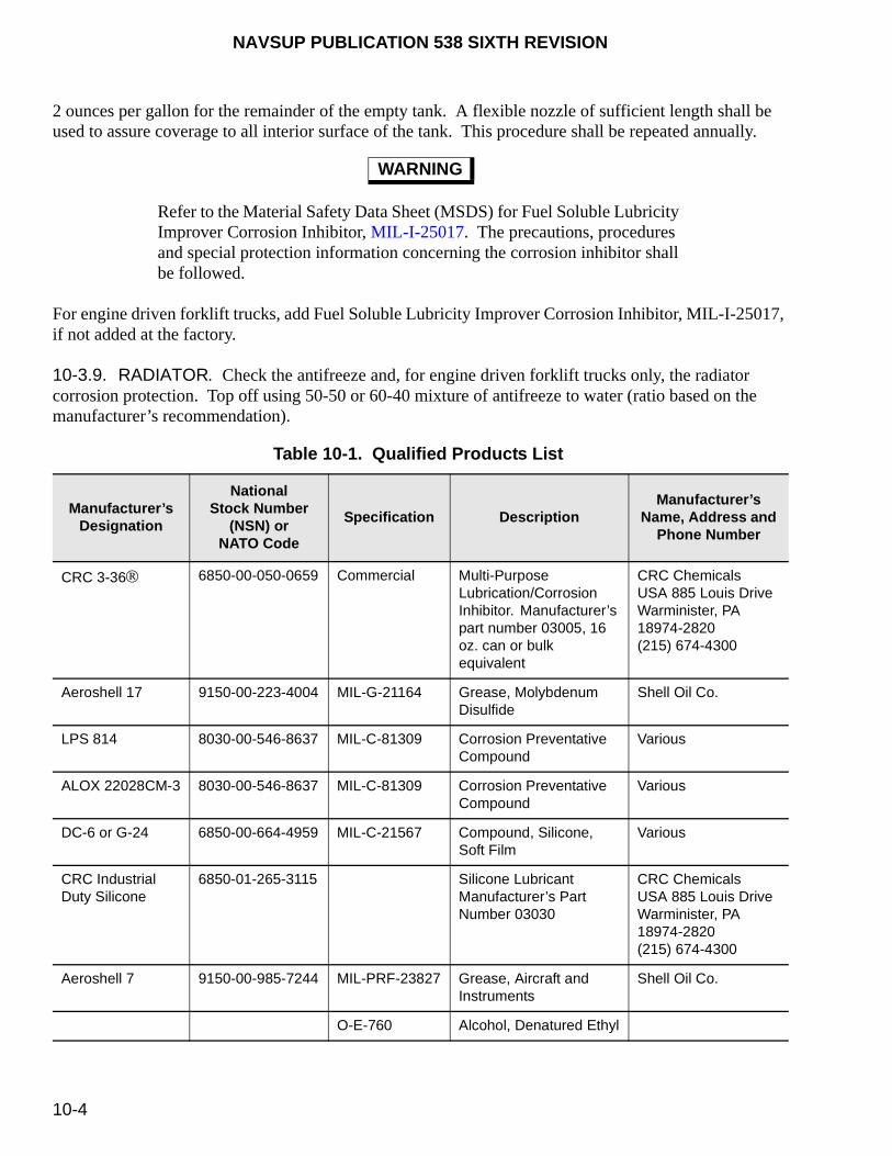
NAVSUP PUBLICATION 538 SIXTH REVISION
10-4
2 ounces per gallon for the remainder of the empty tank. A flexible nozzle of sufficient length shall be used to assure coverage to all interior surface of the tank. This procedure shall be repeated annually.
Refer to the Material Safety Data Sheet (MSDS) for Fuel Soluble Lubricity Improver Corrosion Inhibitor, MIL-I-25017. The precautions, procedures and special protection information concerning the corrosion inhibitor shall be followed.
For engine driven forklift trucks, add Fuel Soluble Lubricity Improver Corrosion Inhibitor, MIL-I-25017, if not added at the factory.
10-3.9. RADIATOR. Check the antifreeze and, for engine driven forklift trucks only, the radiator corrosion protection. Top off using 50-50 or 60-40 mixture of antifreeze to water (ratio based on the manufacturer’s recommendation).
WARNING
Table 10-1. Qualified Products List
Manufacturer’sDesignation
NationalStock Number
(NSN) or NATO Code
Specification DescriptionManufacturer’s
Name, Address and Phone Number
CRC 3-36 6850-00-050-0659 Commercial Multi-Purpose Lubrication/Corrosion Inhibitor. Manufacturer’s part number 03005, 16 oz. can or bulk equivalent
CRC Chemicals USA 885 Louis DriveWarminister, PA 18974-2820 (215) 674-4300
Aeroshell 17 9150-00-223-4004 MIL-G-21164 Grease, Molybdenum Disulfide
Shell Oil Co.
LPS 814 8030-00-546-8637 MIL-C-81309 Corrosion Preventative Compound
Various
ALOX 22028CM-3 8030-00-546-8637 MIL-C-81309 Corrosion Preventative Compound
Various
DC-6 or G-24 6850-00-664-4959 MIL-C-21567 Compound, Silicone, Soft Film
Various
CRC Industrial Duty Silicone
6850-01-265-3115 Silicone LubricantManufacturer’s Part Number 03030
CRC ChemicalsUSA 885 Louis DriveWarminister, PA 18974-2820 (215) 674-4300
Aeroshell 7 9150-00-985-7244 MIL-PRF-23827 Grease, Aircraft and Instruments
Shell Oil Co.
O-E-760 Alcohol, Denatured Ethyl
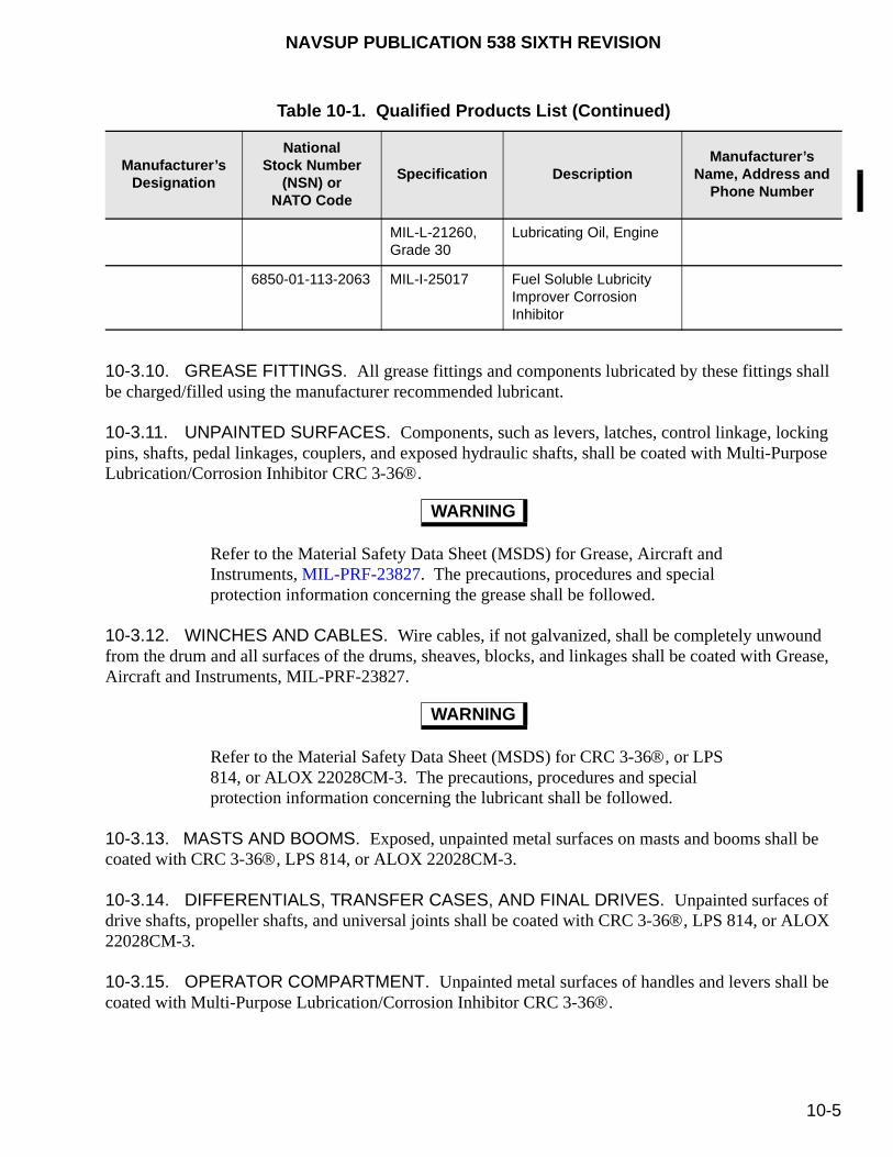
NAVSUP PUBLICATION 538 SIXTH REVISION
10-5
10-3.10. GREASE FITTINGS. All grease fittings and components lubricated by these fittings shall be charged/filled using the manufacturer recommended lubricant.
10-3.11. UNPAINTED SURFACES. Components, such as levers, latches, control linkage, locking pins, shafts, pedal linkages, couplers, and exposed hydraulic shafts, shall be coated with Multi-Purpose Lubrication/Corrosion Inhibitor CRC 3-36.
Refer to the Material Safety Data Sheet (MSDS) for Grease, Aircraft and Instruments, MIL-PRF-23827. The precautions, procedures and special protection information concerning the grease shall be followed.
10-3.12. WINCHES AND CABLES. Wire cables, if not galvanized, shall be completely unwound from the drum and all surfaces of the drums, sheaves, blocks, and linkages shall be coated with Grease, Aircraft and Instruments, MIL-PRF-23827.
Refer to the Material Safety Data Sheet (MSDS) for CRC 3-36, or LPS 814, or ALOX 22028CM-3. The precautions, procedures and special protection information concerning the lubricant shall be followed.
10-3.13. MASTS AND BOOMS. Exposed, unpainted metal surfaces on masts and booms shall be coated with CRC 3-36, LPS 814, or ALOX 22028CM-3.
10-3.14. DIFFERENTIALS, TRANSFER CASES, AND FINAL DRIVES. Unpainted surfaces of drive shafts, propeller shafts, and universal joints shall be coated with CRC 3-36, LPS 814, or ALOX 22028CM-3.
10-3.15. OPERATOR COMPARTMENT. Unpainted metal surfaces of handles and levers shall be coated with Multi-Purpose Lubrication/Corrosion Inhibitor CRC 3-36.
MIL-L-21260, Grade 30
Lubricating Oil, Engine
6850-01-113-2063 MIL-I-25017 Fuel Soluble Lubricity Improver Corrosion Inhibitor
WARNING
WARNING
Table 10-1. Qualified Products List (Continued)
Manufacturer’sDesignation
NationalStock Number
(NSN) or NATO Code
Specification DescriptionManufacturer’s
Name, Address and Phone Number

NAVSUP PUBLICATION 538 SIXTH REVISION
10-6
10-3.16. INSTRUMENT PANELS. Instrument panels, unpainted gauges, instruction plates, data plates, unpainted toggle switches, and any unpainted surfaces on the instrument panel shall be sprayed with Multi-Purpose Lubrication/Corrosion Inhibitor CRC 3-36.
10-3.17. TIRES. Pneumatic tires shall be inflated to 10 pounds above the recommended pressure for maximum load. Spray tire sidewall surface using CRC Industrial Duty Silicone. If tarps do not cover tires completely and the MHE is subjected to ultraviolet light from windows or open doors, protective polyethylene bags/covers shall be applied conforming to MIL-T-46755.
10-3.18. FORKS. Unpainted surfaces on the forks, fork locks, etc., shall be coated with Multi-Purpose Lubrication/Corrosion Inhibitor CRC 3-36.
10-3.19. LIFT CHAINS. Spray lift chains initially with Multi-Purpose Lubrication/Corrosion Inhibitor CRC 3-36, then again every quarter or as required after operational testing.
10-3.20. MAINTENANCE TOOLS. Tools provided as part of the MHE contract shall be initially preserved by atomize spray application of Multi-Purpose Lubrication/Corrosion Inhibitor CRC 3-36. Spray annually thereafter or as conditions require.
10-4. STORAGE
When MHE is to be placed in other than ready-to-ship or ready-to-operate condition for immediate issue on short notice (“live storage”), NAVSUP WSS will ensure that the appropriate corrosion prevention is performed at the factory. The following storage restrictions apply:
a. Outside storage is prohibited.
b. MHE shall be kept dry and in an enclosed area. Keeping the MHE in a low moisture (less than 50% humidity), temperature controlled environment will greatly reduce degradation.
c. MHE shall be covered by tarps, whenever possible. Tarps shall be of cotton, linen or other material that is water permeable (material that does not trap water or allow equipment to sweat, i.e., used parachutes work well). Tarps will help eliminate dirt or dust buildup and ultraviolet light degradation to rubber and plastic components. Plastic sheets or waterproof tarps used to wrap equipment are prohibited. These materials can trap floor moisture and accelerate corrosion. Tarps may be applied loosely to the equipment.
d. Maintenance Requirement Cards (MRC’s) shall be used in conjunction with this publication. The MRC calendar periodicity may be largely ignored, but the hourly maintenance requirement shall be strictly followed. When conflicting information between this publication and the MRC exists, contact NAVSUP WSS for clarification and resolution.
10-5. RECORDS
Each activity will maintain records documenting the identity (type, make, model, size, serial and registration numbers), location, and the condition of the MHE upon arrival, upon examination at each
NAVSUP PUBLICATION 538 SIXTH REVISION
10-7
exercising period, and following removal from storage containing the dates and a description of maintenance performed along with the cost of servicing the MHE.
10-6. STORAGE DOCUMENTATION DATA
The following storage data shall be maintain, where applicable:
a. The date the MHE is placed in storage.
b. Uncorrected deficiencies.
c. Battery readings.
d. Logistics information for all maintenance, inspection, and preservation checks, including the dates and the names of the technicians performing the storage checks.
e. A list of manufacturer recommended fluids and system applications.
f. Date of de-preservation for equipment that is preserved for long term storage (level A or B) as described in chapter 11.
10-7. LUBRICATION CARD
A laminated 8-1/2 by 11-inch card containing the manufacturer recommended lubricants and fill locations may be included with each MHE placed into short term storage.
10-8. PERIODIC INSPECTION, EXERCISING AND MAINTENANCE
Each MHE will be visually inspected at least every 30 days. If deterioration is evident, the equipment shall be preserved to the extent necessary to preclude further deterioration. Every 60 to 90 days, each MHE will be operated and exercised until normal operating temperature is reached or for a minimum period of 15 minutes, whichever occurs first. The equipment shall be maneuvered in all directions (includes crab positions, as applicable) and in all gear ratios. All operational capabilities of the MHE, such as lift, lower, reach, retract, side shift, rotate, etc. shall be tested. The storing activity will inspect and perform corrosion protection and fluid/filter maintenance, as required. Any additional maintenance and repairs requires authorization by NAVSUP WSS.
10-8.1. MONTHLY INSPECTION. The following are the monthly inspection requirements, where applicable:
a. Visually inspect MHE for damage or evidence of corrosion.
b. Apply Multi-Purpose Lubrication/Corrosion Inhibitor CRC 3-36 to piston rods, chains, linkages, and all exposed, unpainted metal surfaces, as required by inspection.
c. Charge and water batteries, and clean, as required.
NAVSUP PUBLICATION 538 SIXTH REVISION
10-8
d. Inspect for any fluid leaks.
10-8.2. BIMONTHLY INSPECTION. The following are the bimonthly (once every 2 months) inspection requirements, where applicable:
a. Visually inspect MHE for damage or evidence of corrosion.
b. Apply Multi-Purpose Lubrication/Corrosion Inhibitor CRC 3-36 to unpainted metal surfaces, as required, after operational testing (hydraulic pistons, chains, rollers, linkages, stack valves, etc.).
c. Charge and water batteries, and clean, as required.
d. Inspect for any fluid leaks.
e. Top off fluid levels, as required.
f. Perform operational tests. Record abnormal operations or noises and report them to NAVSUP WSS.
g. Inspect gages to ensure proper operation of the MHE.
NOTE
When performing operational testing, care should be taken to avoid dirt and debris from embedding into the tires.
h. Fill dehydrator/evaporators, as appropriate (engine driven forklift trucks only).
i. Drain moisture from air actuated brake systems (engine driven forklift trucks only).
j. Drain water from fuel filters (engine driven forklift trucks only).
k. Inspect for tire damage and proper inflation pressure.
l. Disconnect battery (if forklift truck is not equipped with a master disconnect switch).
10-8.3. QUARTERLY INSPECTION. The following are the quarterly inspection requirements, where applicable:
a. Perform a battery equalizing charge in accordance with paragraph 9-9. Record the specific gravity and temperature. Battery specific gravity levels below 25% of the original level (e.g., 1.300 original, followed by 1.275) shall be considered suspect. Notify NAVSUP WSS for warranty assistance.
b. Perform all bimonthly operational, inspection, maintenance and preservation checks in accordance with paragraph 10-8.2.
NAVSUP PUBLICATION 538 SIXTH REVISION
10-9
c. Check and maintain fuel levels. Add fuel stabilizers, as required (engine driven forklift trucks only).
d. Lubricate grease fittings, as required.
e. Drain moisture from fuel filters (engine driven forklift trucks only).
f. Clean battery, as required. Apply corrosion preventative to battery connectors.
10-8.4. SEMI-ANNUAL INSPECTION. The following are the semi-annual inspection requirements, where applicable:
a. Inspect wiring harness for corrosion, abrasion, loose connections, or other defects. Clean and preserve, as required.
Refer to the Material Safety Data Sheet (MSDS) for Alcohol, Denatured Ethyl, O-E-760. The precautions, procedures and special protection information concerning the cleaning solvent shall be followed.
b. Inspect contactors (electrically powered forklift trucks only) for corrosion, and clean, as required, using Alcohol, Denatured Ethyl, O-E-760 or a commercial contact cleaner.
c. Inspect fuse blocks, fuses, and connectors for corrosion. Clean and apply Multi-Purpose Lubrication/Corrosion Inhibitor CRC 3-36, as required.
d. Perform all bimonthly operational, inspection, maintenance and preservation checks in accordance with paragraph 10-8.2.
10-8.5. ANNUAL INSPECTION. The following are the annual inspection requirements, where applicable:
a. Inspect the ether cylinder (cold start). Change or fill, as required (diesel only).
b. Sample coolant for corrosion and antifreeze protection. Change, as required (engine driven forklift trucks only).
c. Sample lubricants and fluids. Change, as required.
d. Top off fluids, as required, to maintain full levels.
e. Check the condition of the air filter, belts, fuel lines, brake lines, and hydraulic lines. Repair and replace, as required.
f. Clean MHE. MHE with tarps are exempt from cleaning, depending on its condition.
WARNING
NAVSUP PUBLICATION 538 SIXTH REVISION
10-10
NOTE
Be extremely careful around controller and contactor panels to prevent water intrusion (electrically powered forklift trucks only).
g. Perform corrosion control procedures upon completion of cleaning and drying the MHE.
h. Bleed the brake system at the lowest point on the vehicle.
i. Perform quarterly and semi-annual operational, inspection, maintenance, and preservation checks in accordance with paragraphs 10-8.3 and 10-8.4, respectively.
j. Perform fuel tank maintenance on MHE so equipped with less than full tanks.
k. Spray electrical connector plugs with Multi-Purpose Lubrication/Corrosion Inhibitor CRC 3-36.
l. Purge fuel from tank in gasoline-powered vehicles and refill to capacity with fresh replacement. Use fuel for powering non-tactile vehicles.
m. Add fuel conditioner, as required.
10-8.6. BIANNUAL (24 MONTH) INSPECTION. The following are the biannual inspection requirements, where applicable:
a. Purge fuel tank from petroleum fuel powered vehicles and refill to capacity with fresh
a. replacement. Use purged fuel for powering non-tactile vehicle.
b. Add fuel conditioner, as required.
c. Perform annual operational, inspection, maintenance, and preservation checks in accordance with paragraph 10-8.5.
10-9. SHIPMENT AND TRANSPORTATION OF MHE
Appendix D provides general guidelines for the shipment and transportation of MHE from short term storage. These procedures will ensure that MHE will not be degraded or damaged during shipment.
NAVSUP PUBLICATION 538 SIXTH REVISION
11-1
CHAPTER 11
LONG TERM (DEAD) STORAGE
11-1. PURPOSE
NOTE
At the present time, short term (dead) storage requirements are not planned for mobile cargo cranes, aerial work platforms or diesel conveyor belt vehicles. Therefore the information contained in this chapter is not applicable.
Materials Handling Equipment (MHE) storage procedures were developed to minimize equipment degradation while in storage prior to issuance. The requirements for storage are divided into two separate categories based on anticipated storage duration. This chapter describes long term procedures, commonly called “dead storage,” for an anticipated MHE storage duration of greater than 24 months (2 years). Chapter 10 describes short term procedures, commonly called “live storage,” procedures for MHE storage of less than 24 months (2 years). Long term (dead) storage refers to MHE that requires complete preservation upon receipt and a thorough de-preservation of all major systems prior to issue. Two military levels of preservation, as described in MIL-STD-2073, are Level “A” and Level “B”. Level A requires protection to meet the most severe worldwide shipment, handling, and storage conditions. Level B requires protection to meet moderate worldwide shipment, handling, and storage conditions. For the purpose of this publication, level “A” shall be used.
11-2. RECEIPT INSPECTION
MHE received at a storage site will be thoroughly inspected prior to being prepared for long term storage. MHE received in unpreserved condition shall be operationally tested to determine whether deficiencies exist that may be covered under the contract warranty. The receiving activity will complete the inspections and operations, documented in paragraph 8-4, prior to signing any documents [i.e., government bill of lading (GBL), shipper’s GBL, etc.)], which may serve to release the shipping company of responsibility for damage incurred during transport. If the receiving activity fails to perform these receipt functions and shipping damage is subsequently identified, the receiving activity may be assigned the responsibility for those damages. Report any equipment deficiencies or warranty defects on the Product Quality Deficiency Report (QDR) (Standard Form 368), figure 6-2, to the MHE Program Manager at Commander, NAVSUP Weapon Systems Support (NAVSUP WSS), Code 8341, 5450 Carlisle Pike, P.O. Box 2020, Mechanicsburg, PA 17055-0788 with a copy to the Director, Naval Surface Warfare Center, Indian Head Division Detachment Picatinny, Naval PHST Center (Code G1), Building 458, Whittemore Avenue, Picatinny Arsenal, New Jersey 07806-5000 is preserved for long term (dead) storage shall be inspected with systems re-preserved as required to assure that the equipment will not degrade further during storage.
NAVSUP PUBLICATION 538 SIXTH REVISION
11-2
11-3. SYSTEM PRESERVATION
The following preservation procedures, where applicable, shall be applied to each MHE:
11-3.1. CLEANING. MHE may be cleaned by any method or combination of processes that will not damage or degrade components or systems. The following are general cleaning requirements:
a. Exterior surfaces and interior surfaces of cabs and bodies shall be clean and free of dirt, dust, grease, and other contaminants.
b. MHE shall be clean and dry prior to the application of preservation compounds.
Refer to the Material Safety Data Sheet (MSDS) for Cleaning Compound, P-C-437. The precautions, procedures and special protection information concerning the compound shall be followed.
NOTE
Cleaning Compound, P-C-437, contains phosphates and shall not be used in countries or areas that prohibit its use.
c. Tape openings and seal with barrier material to prevent moisture intrusion prior to washing.
d. For power washing or steam cleaning, use Cleaning Compound, P-C-437. Do not spray directly into lights, wiring harnesses, wire loom connectors, bearings, axles shafts, engine components, exhaust systems, etc. Do not direct spray as to remove markings or paint from components.
11-3.2. DRYING. MHE may be dried using prepared compressed air. The air stream of prepared (filtered and dried air) shall be directed away from components. Wiping rags or wiping papers may be used provided they are linen, combed cotton or lint free, non-woven fabric as listed by General Services Administration (GSA).
11-3.3. PAINTING. Painted surfaces on which the paint film has been damaged shall be repainted after cleaning using compatible materials (e.g., same type, quality and color) as original or as required by specification.
Refer to the Material Safety Data Sheet (MSDS) for Antifreeze, A-A-52624. The precautions, procedures and special protection information concerning the antifreeze shall be followed.
11-3.4. LIQUID COOLANT SYSTEM. The coolant system shall be drained and filled with a pre-mixed solution of antifreeze and distilled water. Engines with thermostatically, controlled coolant
WARNING
WARNING

NAVSUP PUBLICATION 538 SIXTH REVISION
11-3
systems shall be operated until temperature is reached that opens thermostats assuring system protection. Top off using 50-50 or 60-40 mix of antifreeze to water [ratio depends on original equipment manufacturer (OEM) recommendation and storage temperature]. Antifreeze, if not specified by the OEM shall be in accordance with specification, A-A-52624, heavy duty, concentrate type (refer to table 11-1). Attach a warning tag (A-A-1266, Type 2) with the notation, “Preserved Month/Year With Antifreeze Type.”
11-3.5. TRANSMISSIONS. The following preservation procedures shall be applied to transmission on each MHE.
Refer to the Material Safety Data Sheet (MSDS) for Lubricating Oil, Combat/Tactical 15W-40 in accordance with MIL-PRF-2104, or Lubricating Oil, Gear, Multi-Purpose in accordance with SAE J2360 (supersedes MIL-PRF-2105). The precautions, procedures and special protection information concerning these oils shall be followed.
WARNING
Table 11-1. Qualified Products List
Manufacturer’sDesignation
NationalStock Number
(NSN) orNATO Code
Specification DescriptionManufacturer’s
Name, Address and Phone Number
CRC 3-36 6850-00-050-0659 Commercial Multi-Purpose Lubrication/Corrosion Inhibitor. Manufacturer’s part number 03005, 16 oz. can or bulk equivalent
CRC Chemicals USA 885 Louis DriveWarminister, PA 18974-2820 (215) 674-4300
Aeroshell 17 9150-00-223-4004 MIL-G-21164 Grease, Molybdenum Disulfide
Shell Oil Co.
LPS 814 8030-00-546-8637 MIL-C-81309 Corrosion Preventative Compound
Various
ALOX 22028CM-3 8030-00-546-8637 MIL-C-81309 Corrosion Preventative Compound
Various
DC-6 or G-24 6850-00-664-4959 MIL-C-21567 Compound, Silicone, Soft Film
Various
CRC IndustrialDuty Silicone
6850-01-265-3115 Silicone LubricantManufacturer’s Part Number 03030
CRC ChemicalsUSA 885 Louis DriveWarminister, PA 18974-2820 (215) 674-4300
Aeroshell 7 9150-00-985-7244 MIL-PRF-23827 Grease, Aircraft and Instruments
Shell Oil Co.

NAVSUP PUBLICATION 538 SIXTH REVISION
11-4
**Manufacturer’s designator not available.
11-3.5.1. Standard (Synchromesh) Drive. Fill the transmission to its operating level with the OEM recommended oil grade conforming to Lubricating Oil, Combat/Tactical 15W-40 in accordance with MIL-PRF-2104 or Lubricating Oil, Gear, Multi-Purpose in accordance with SAE J2360 (supersedes MIL-PRF-2105) using the manufacturer’s technical manual. Operate the transmission through all ranges to distribute corrosion resistant oil to all surfaces. Atomize spray transmission and dip stick fill tubes with Multi-Purpose Lubrication/Corrosion Inhibitor, CRC 3-36. Seal all breather vents and tubes using Tape, Waterproof, L-T-100, Type 2. Attach a red warning tag, A-A-1266, Type 2, to the transmission operating lever indicating, “Transmission preserved with (insert applicable oil type) and month/year.”
** O-E-760 Alcohol, Denatured Ethyl
Various
Ashlandar Oil 30,Sunsolvent 2650A
9150-00-111-3199 MIL-L-21260, grade 30
Lubricating Oil, Engine Various
** 6850-01-113-2063 MIL-I-25017 Fuel Soluble Lubricity Improver Corrosion Inhibitor
Various
** A-A-52624 Antifreeze Various
** A-A-51461 Antifreeze Tester Various
** MIL-B-131 Type 1 Class B
Bags, Waterproof Various
** 6850-00-965-2330 P-C-437 Cleaning Compound Various
** NAS 847 Cap Plugs Various
** L-T-100 Type 2 Tape, Waterproof Various
** A-A-1266 Type 2
Tags, Warning, Red Various
** MIL-P-46002 Type 1
Preservative Oil, Light Viscosity
Various
** MIL-PRF-2104 Lubricating Oil Combat/Tactical 15W-40
Various
** O-228 SAE J2360 (supersedes MIL-PRF-2105)
Lubricating Oil Multi-Purpose
Various
Table 11-1. Qualified Products List (Continued)
Manufacturer’sDesignation
NationalStock Number
(NSN) orNATO Code
Specification DescriptionManufacturer’s
Name, Address and Phone Number
NAVSUP PUBLICATION 538 SIXTH REVISION
11-5
11-3.5.2. Automatic Drive. Fill the transmission to its operating level with a lubricant recommended by the OEM. Atomize spray transmission and dip stick fill tubes with Multi-Purpose Lubrication/Corrosion Inhibitor CRC 3-36. Seal all breather vents and tubes using Tape, Waterproof, L-T-100, Type 2.
11-3.5.3. Transmission Case. The transmission outer case shall be sprayed with Multi-Purpose Lubrication/Corrosion Inhibitor CRC 3-36. All tie rod and linkages shall be preserved with Grease, Aircraft and Instruments, MIL-PRF-23827 (refer to table 11-1).
11-3.6. FLYWHEEL RING GEAR. Atomize spray the flywheel ring gear with a film of Multi-Purpose Lubrication/Corrosion Inhibitor CRC 3-36
11-3.7. DISC TYPE CLUTCH (DRY TYPE). Clutch control mechanisms not enclosed shall be coated with Multi-Purpose Lubrication/Corrosion Inhibitor CRC 3-36 after removing the cover plate. Spring-loaded type clutch mechanisms shall have the clutch pedal secured in a partially disengaged position to eliminate contact with the disc face and the pressure plate. Snap-over-center and toggle-in type clutches shall be completely disengaged.
11-3.8. FUEL SYSTEMS. A portable fuel preservation tank containing two compartments shall be positioned to provide gravity feed to the engine. One compartment shall contain Preservative Oil, Light Viscosity, MIL-P-46002, Type 1 (refer to table 11-1). The other compartment shall contain the designated fuel type (diesel or gas) used by the engine under preservation. The preservation tank shall contain a manual selector valve in line with the fuel source compartment allowing switching between the compartments. The fuel supply line from the engine shall be disconnected at a convenient point. Connect the fuel supply line from the portable tank to the engine. The engine shall be started and operated at a fast idle until running smoothly. Accelerate the engine (with no load) until half speed and switch to the preservation oil tank. When the preservative oil reaches the combustion chambers, evidenced by a loss of engine speed and smoking, shut the ignition to the “off” position.
11-3.9. FUEL FILTERS. Drain fuel filters, sediment bowls and water separators. Reconnect the fuel supply after draining.
11-3.10. FUEL TANKS. Drain fuel tanks completely of fuel.
Refer to the Material Safety Data Sheet (MSDS) for Preservative, Oil, Light Viscosity, MIL-P-46002, Type 1. The precautions, procedures and special protection concerning the oil shall be followed.
a. Fuel tanks without baffles shall be atomize sprayed with Preservative Oil, Light Viscosity, MIL-P-46002, Type 1, using a flexible nozzle of sufficient length to assure coverage of all tank interior surfaces. Two ounces (2 oz.) of Preservative Oil, Light Viscosity, MIL-P-46002, Type 1, per gallon of interior space shall be used.
WARNING
NAVSUP PUBLICATION 538 SIXTH REVISION
11-6
Refer to the Material Safety Data Sheet (MSDS) for Lubricating Oil, Engine, MIL-L-21260, Grade 30. The precautions, procedures and special protection information concerning the oil shall be followed.
b. Fuel tanks with baffles shall be filled with oil conforming to Lubricating Oil, Engine, MIL-L-21260, Grade 30 (refer to table 11-1). The oil may remain in the tank, or can be drained into a recovery system and reused. The recovered mixture shall be discarded when contaminated with fuel greater than 10%. Attach a red warning tag, A-A-1266, Type 2, stating, “Fuel tank preserved with Lubricating Oil, Engine, MIL-L-21260, Grade 30.”
11-3.11. ENGINE CRANKCASE. Fill the engine crankcase to the maximum safe operating level with oil conforming to Lubricating Oil, Engine, MIL-L-21260, Grade 30. Upon completion, affix a red warning tag, A-A-1266, Type 2, to the fill tube stating, “Crankcase filled to operating level with preservative Lubricating Oil, Engine, MIL-L-21260, Grade 30. Drain and refill prior to operating.”
NOTE
Allow engine cylinder temperature to cool to a maximum temperature of 100 degrees Fahrenheit (100 °F) prior to engine cylinder preservation.
NOTE
The mating locations on engine parts and accessories removed shall be match-marked when necessary to facilitate re-assembly and shall be identified with a red warning tag, A-A-1266, Type 2, attached to the mating parts and locations, as required.
11-3.12. ENGINE CYLINDER PRESERVATION. The following procedures pertain to engine cylinder preservation:
a. Remove spark plugs, fuel injectors, glow plugs, etc. Remove only those items to allow access to engine cylinders.
b. Inject Preservative Oil, Light Viscosity, MIL-P-46002, Type 1, by atomize spray method into each engine cylinder using the amount listed below:
(1) 25 cubic inches (cu. in.) or less [409.75 cubic centimeters (cc)] - atomize spray with 1/2 ounce (0.5 oz.) of MIL-P-46002, Type 1.
(2) 25-50 cu. in. (409.75 to 819.5 cc) – atomize spray one ounce (1 oz.) per cylinder of MIL-P-46002, Type 1.
(3) 50-75 cu. in. (819.5 to 1229.25 cc) – atomize spray 1-1/2 ounces (1.5 oz.) per cylinder of MIL-P-46002, Type 1.
WARNING
NAVSUP PUBLICATION 538 SIXTH REVISION
11-7
(4) 75 cu. in. (1229.25 cc) or larger – atomize spray two ounces (2 oz.) per cylinder of MIL-P-46002, Type 1.
Precautions must be taken to assure hydrostatic lock-up does not occur causing severe engine damage. Spark plugs, fuel injectors, glow plugs, etc., must remain out during this procedure or engine damage may result.
c. Slowly rotate the engine crank shaft manually (preferred method) or by using the starter motor for four revolutions to distribute the preservative oil. Lightly coat items previously removed with Preservative Oil, Light Viscosity, MIL-P-46002, Type 1 and re-assemble.
d. Tape engine breathers, vent tubes, etc., using Tape, Waterproof, L-T-100, Type 2.
e. Place a red warning tag, A-A-1266, Type 2, near the engine starter control stating, “Engine Preserved. Do Not Crank.”
11-3.13. ENGINE BLOCK. Engine blocks shall be sprayed using Multi-Purpose Lubrication/Corrosion Inhibitor CRC 3-36. Rubber or plastic engine hoses shall be sprayed using CRC Industrial Duty Silicone (refer to table 11-1).
11-3.14. AIR INTAKE. The air cleaner shall be removed and one ounce (1 oz.) of preservative oil conforming to Preservative Oil, Light Viscosity, MIL-P-46002, Type 1, shall be atomize sprayed into the air intake tube. The air intake shall be immediately sealed with Tape, Waterproof, L-T-100, Type 2.
11-3.15. TURBOCHARGER/SUPERCHARGER. Disconnect the tube between the intake manifold/charger and the air cleaner/charger. Atomize spray one ounce (1 oz.) of Preservative Oil, Light Viscosity, MIL-P-46002, Type 1, into the air intake toward the charger. Spray one ounce (1 oz.) of additional oil toward the charger from the outlet side.
11-3.16. AIR CLEANER.
a. Oil Bath Type. Oil bath type air cleaners shall be filled to its operating level with Lubricating Oil, Engine, MIL-L-21260, Grade 30. Metallic elements shall be dipped in Preservative Oil, Light Viscosity, MIL-P-46002, Type 1, whenever possible for complete coverage. Atomize spray all other surfaces of the air cleaner assembly using Preservative Oil, Light Viscosity, MIL-P-46002, Type 1.
b. Dry Type. Remove the dry element. Atomize spray the interior surfaces with Preservative Oil, Light Viscosity, MIL-P-46002, Type 1. Reinstall the element.
11-3.17. AIR INTAKE SEALING. After the air cleaner elements have been preserved and reinstalled, the air intake shall be sealed with Tape, Waterproof, L-T-100, Type 2.
11-3.18. DRIVE BELTS. Relieve all tension from the drive belts. Drive belts may remain in position provided the pulleys can be preserved.
CAUTION
NAVSUP PUBLICATION 538 SIXTH REVISION
11-8
11-3.19. DRIVE PULLEYS. Unpainted surfaces of the drive pulleys shall be sprayed with Multi-Purpose Lubrication/Corrosion Inhibitor CRC 3-36.
11-3.20. EXHAUST SYSTEM. Atomize spray the exhaust system components with one ounce (1 oz.) of Preservative Oil, Light Viscosity, MIL-P-46002, Type 1 for each two feet (2 ft.) of pipe. The spray coat shall be applied to the outside and inside of the pipe. The system shall immediately be sealed with plastic plugs conforming to specification, NAS 847, or Tape, Waterproof, L-T-100, Type 2.
11-3.21. BRAKE SYSTEM. Metal surfaces, such as adjusting wedges, pins, eccentrics, cam levers, linkages, anchors, retracting springs, and surfaces of brake drums and brake rotors (both external and internal), shall have surfaces sprayed with Multi-Purpose Lubrication/Corrosion Inhibitor CRC 3-36.
Mask friction-type brake linings from overspray. Damage to lining material will result.
11-3.22. BRAKE AIR COMPRESSOR. The brake air compressor shall be filled to operating level with 10W oil conforming to Lubricating Oil, Engine, MIL-L-21260, Grade 30. A red warning tag, A-A-1266, Type 2, indicating, “Preservation Performed. Drain Before Operating,” shall be attached near the air compressor.
11-3.23. AIR SUPPLY TANKS. Atomize spray the interior and exterior surfaces of the air supply tanks using Multi-Purpose Lubrication/Corrosion Inhibitor CRC 3-36.
11-3.24. AIR LINE FILTERS. Air line filters shall be drained and closed. Exhaust ports of emergency quick release and relay valves shall be sealed using Tape, Waterproof, L-T-100, Type 2.
11-3.25. HYDRAULIC PISTONS. Hydraulic pistons shall remain in the lowest or “relaxed” position. Spray the exposed piston surface initially with Multi-Purpose Lubrication/Corrosion Inhibitor CRC 3-36. Wipe clean and apply Grease, Aircraft and Instruments, MIL-PRF-23827 to the exposed piston.
Refer to the Materials Safety Data Sheet (MSDS) for CRC Industrial Duty Silicone. The precautions, procedures and special protection information concerning silicone shall be followed.
11-3.26. HYDRAULIC HOSES AND FITTINGS. Spray hoses and fitting components using CRC Industrial Duty Silicone.
11-3.27. HYDRAULIC VALVES. Hydraulic valves (spool, stack, etc.) shall be sprayed with Multi-Purpose Lubrication/Corrosion Inhibitor CRC 3-36. A film of Grease, Aircraft and Instruments, MIL-PRF-23827 shall be applied over all actuating rods.
CAUTION
WARNING

NAVSUP PUBLICATION 538 SIXTH REVISION
11-9
11-3.28. GREASE FITTINGS. All grease fittings and parts lubricated by these fittings shall be charged/filled to capacity with an OEM recommended lubricant.
11-3.29. DIFFERENTIALS, TRANSFER CASES, AND FINAL DRIVES. Unpainted surfaces of drive shafts, propeller shafts, and universal joints shall be coated with CRC 3-36, LPS 814, or ALOX 22028CM-3.
11-3.30. UNPAINTED COMPONENTS. Components, such as levers, latches, control linkage, locking pins, shafts, pedal linkages, couplers, and exposed hydraulic shafts, shall be coated with Multi-Purpose Lubrication/Corrosion Inhibitor CRC 3-36.
11-3.31. MASTS AND BOOMS. Exposed, unpainted metal surfaces of masts and booms shall be coated with CRC 3-36, LPS 814, or ALOX 22028CM-3.
11-3.32. WINCHES AND CABLES. Wire cable, if not galvanized, shall be completely unwound from the drum and all surfaces of the drums, sheaves, blocks, and linkages shall be coated with Grease, Aircraft and Instruments, MIL-PRF-23827.
11-3.33. OPERATOR COMPARTMENT. Unpainted metal surfaces of handles and levers shall be coated with Multi-Purpose Lubrication/Corrosion Inhibitor CRC 3-36.
11-3.34. INSTRUMENT PANELS. Instrument panels, unpainted gauges, instruction plates, data plates, unpainted toggle switches, and any unpainted surfaces shall be sprayed with Multi-Purpose Lubrication/Corrosion Inhibitor CRC 3-36.
11-3.35. SEAT BELT COUPLERS. Chrome or metal surfaces and spring-loaded interlock mechanisms shall be sprayed with Multi-Purpose Lubrication/Corrosion Inhibitor CRC 3-36.
11-3.36. WIRING HARNESS. Spray wiring harness connector plugs with Multi-Purpose Lubrication/Corrosion Inhibitor CRC 3-36.
11-3.37. FUSE BLOCKS. Spray a thin film of Multi-Purpose Lubrication/Corrosion Inhibitor CRC 3-36 on all fuse lugs and conductor lugs that are unpainted.
11-3.38. TIRES. Pneumatic tires shall be inflated to the maximum pressure recommended for the tire. Spray tire sidewall surface using CRC Industrial Duty Silicone. Raise the vehicle until the tires are free to rotate and block MHE securely. If tarps do not cover the tires completely and the MHE is subject to ultraviolet light from windows or open doors, protective polyethylene bags or covers conforming to MIL-T-46755 shall be applied.
11-3.39. FORKS. Unpainted surfaces of the forks, fork locks, etc., shall be coated with CRC 3-36, LPS 814, or ALOX 22028CM-3.
11-3.40. LIFT CHAINS. Spray lift chains with CRC 3-36, LPS 814, or ALOX 22028CM-3.

NAVSUP PUBLICATION 538 SIXTH REVISION
11-10
Refer to the Material Safety Data Sheet (MSDS) for Compound, Silicone, Soft Film, DC-6 or G-24. The precautions, procedures and special protective information concerning the compound shall be followed.
11-3.41. LIGHTS. Preserve all light devices by removing protective lenses. Coat sockets and bulb bases using Compound, Silicone, Soft Film, DC-6 or G-24 (refer to table 11-1).
11-3.42. BATTERIES. Batteries shall be removed and stored if unfilled with electrolyte. Batteries filled with electrolyte shall have the specific gravity and open circuit voltage recorded using the battery record form shown in figure 9-2 for baseline purposes. Refer to the procedures in chapter 9 for safety precautions when performing these measurements. A commercially available equivalent form of battery record recording may be used if authorized by the appropriate NAVSUP Fleet Logistics Center (NAVSUP FLC) [formerly Fleet and Industrial Supply Center (FISC)] Regional Manager. Perform these inspections in accordance with the battery manufacturer’s recommendations to ensure full coverage of the manufacturer’s warranty.
a. Batteries shall be maintained as close to 100% of capacity as economical. At no time shall the batteries be allowed to discharge below 1.240 specific gravity without charging. Charge batteries, as required, whenever the battery cell voltage falls below 25% of the initial reading. Batteries shall be maintained in a charged ready state either in the forklift truck or a separate battery room location.
b. Charge batteries if the specific gravity is below 25% of the manufacturer’s full charge recommendation. Ensure a constant current, constant voltage, constant current charging method [current voltage current (IEI)] is used to prevent battery overcharging. High rate shall not exceed 16-18 amps per 100 amp hour of rated capacity, constant current.
NOTE
Use caution when servicing forklift trucks with battery box covers using cover support rods (type E/EE/EX) and safety interlocks (type EX only). Damage to battery, battery cables, and switches may occur when the battery cover is lowered without properly positioning the supports/interlocks.
c. Add distilled water only as required for battery cell replacement.
Refer to the Material Safety Data Sheet (MSDS) for Grease, Aircraft and Instruments, MIL-PRF-23827. The precautions, procedures and special protection information concerning the grease shall be followed.
d. Apply Grease, Aircraft and Instruments, MIL-PRF-23827 (refer to table 11-1) or a commercial equivalent to the battery terminals and connectors.
WARNING
WARNING

NAVSUP PUBLICATION 538 SIXTH REVISION
11-11
e. Battery cable connectors for electrically driven MHE shall be disconnected. Spray Multi-Purpose Lubrication/Corrosion Inhibitor CRC 3-36 to the battery connector contacts.
f. Battery Compartment. Clean and preserve the battery compartment using Preservative Oil, Light Viscosity, MIL-P-46002, Type 1, or Multi-Purpose Lubrication/Corrosion Inhibitor CRC 3-36.
g. Maintenance Tools. Maintenance tools supplied as part of the MHE contract shall be preserved by atomize spray application of Multi-Purpose Lubrication/Corrosion Inhibitor CRC 3-36. The tools shall be sealed in a waterproof bag conforming to MIL-B-131, Type 1, Class B.
h. Repair Parts. Apply Multi-Purpose Lubrication/Corrosion Inhibitor CRC 3-36 to non-electric repair parts. Place these parts in a sealed bag conforming to MIL-B-131, Type 1, Class B (heavy duty waterproof).
i. Technical Manuals. Waterproof bags shall be used for storing instruction and operating manuals. Items to be preserved together and sealed in a waterproof bag shall have projections, sharp edges, or other features padded to protect the contents and bag with commercial bubble wrap or an equivalent non-permeable material. The waterproof bag shall be in accordance with MIL-B-131, Type 1, Class B (heavy duty waterproof).
11-4. STORAGE
Long term (dead) storage requires additional environmental controls to ensure MHE does not degrade during storage. These controls are identified as follows:
a. Inside storage is required.
b. MHE shall be kept clean and dry in an enclosed, rodent-free area. Keeping the MHE in a low moisture (less than 50% humidity), temperature controlled environment will greatly reduce degradation.
c. Forklift trucks may be encased in “cocoon-type” storage bags, when available. However, as a minimum, MHE shall be covered by a tarp constructed of cotton, linen, or other material (used parachutes work well) that is water permeable (material that does not trap water or allow equipment to sweat). Tarps help eliminate dirt or dust buildup and ultraviolet light degradation to rubber and plastic components. Plastic sheets or waterproof tarps used to wrap MHE is prohibited. These materials can trap floor moisture and accelerate corrosion. Tarps may be applied loosely over the equipment.
d. Maintenance Requirement Cards (MRCs) shall be used in conjunction with this publication for use in the preservation/de-preservation process. When conflicting data between this publication and the MRC exist, contact the NAVSUP WSS for clarification and resolution.
11-5. RECORDS
Each activity will maintain records documenting the identity (type, make, model, size, serial and registration numbers), location, condition, servicing, processing, and repairs performed for each piece of equipment. Each record will indicate the condition of the MHE upon arrival, upon being placed in

NAVSUP PUBLICATION 538 SIXTH REVISION
11-12
storage, preservation performed, preservations used, condition of equipment at inspection intervals, and maintenance performed to allow for continued storage. De-preservation records shall identify the length of storage with dates, de-preservation hours, cost of material, and additional maintenance prior to issue, if any.
11-6. STORAGE DOCUMENTATION DATA
The following storage data shall be maintained, where applicable:
a. The date the MHE is placed in storage.
b. Uncorrected deficiencies.
c. Battery readings (does not apply to dry batteries without electrolyte).
d. Logistics information for all maintenance, inspection, and preservation checks performed, including the dates and the names of the technicians performing the storage checks.
e. A list of manufacturer recommended fluids and system applications.
f. Date of preservation for MHE that is preserved for long term storage.
g. Applicable MRC used during de-preservation.
11-7. LUBRICATION CARD
A laminated 8-1/2 by 11-inch card containing the manufacturer recommended lubricants and fill locations may be included with each MHE placed into long term storage.
11-8. PERIODIC INSPECTION AND EXERCISING
Each MHE, as a minimum, will be visually inspected annually. Due to storage conditions in some remote locations, inspection monitoring may be increased (reduced in time) as required. If deterioration is evident, the equipment shall be corrected and preserved to the extent necessary to preclude further deterioration. Batteries filled with electrolyte shall be on permanent float charge or charged a minimum of once every 30 days. Dry charged batteries shall be kept clean and dry. The storing activity will inspect and perform corrosion protection as required. Any additional maintenance and repairs requires authorization by NAVSUP WSS.
11-8.1. ANNUAL INSPECTION. The following are the annual inspection requirements, where applicable:
a. Visually inspect MHE for damage or evidence of corrosion.
NAVSUP PUBLICATION 538 SIXTH REVISION
11-13
b. Clean and apply corrosion preventive compounds removed during inspection. Particular attention should be made to the brake rotors and drums, hydraulic pistons, chains, cables, rubber parts, and any other components not covered with organic coatings (paint).
c. Inspect for any fluid leaks.
d. Test coolant system for corrosion/temperature protection.
e. Visually inspect all fluid levels.
f. Top off fluid levels, as required.
g. Inspect all fluid, fuel, hydraulic, and air tanks for evidence of corrosion. Preserve as required.
h. Maintain inspection records and components that require representation.
11-8.2. BIANNUAL (24 MONTH) INSPECTION. The following are the biannual inspection requirements, where applicable:
a. Perform annual operational, inspection, maintenance, and preservation checks in accordance with paragraph 11-8.1.
b. Lubricate grease fittings.
c. Inspect wiring harness for corrosion, abrasion, loose connections, or other defects. Clean and preserve as required.
Refer to the Material Safety Data Sheet (MSDS) for Alcohol, Denatured Ethyl, O-E-760. The precautions, procedures and special protection information concerning the cleaning solvent shall be followed.
d. Inspect contactors (electrically powered forklift trucks only) for corrosion. Clean, as required, using Alcohol, Denatured Ethyl, O-E-760 (refer to table 11-1) or a commercial contact cleaner equivalent.
NOTE
Do not use emery or sand paper to clean contact tips of contactors.
e. Inspect fuse blocks, fuses and connectors for corrosion. Clean and apply Multi-Purpose Lubrication/Corrosion Inhibitor CRC 3-36 as required.
f. Sample lubricants and fluids. Change as required.
WARNING
NAVSUP PUBLICATION 538 SIXTH REVISION
11-14
NOTE
MHE that uses DOT 5 Silicone Brake Fluid, MIL-B-46176, or other types of lubricating oil (MIL-L-2104 or SAE J2360) are exempt from the biannual brake bleeding requirement.
g. Bleed brake system using a power or vacuum-type bleeder unit at the lowest point on the equipment. This is applicable to equipment that uses DOT 3 or DOT 4 (VV-B-680) brake fluid types.
h. Perform engine cylinder preservation in accordance with paragraph 11-3.12.
i. Electrically powered forklift trucks shall have the motors rotated to distribute the lubricant.
j. Spray electrical connector plugs with Multi-Purpose Lubrication/Corrosion Inhibitor CRC 3-36.
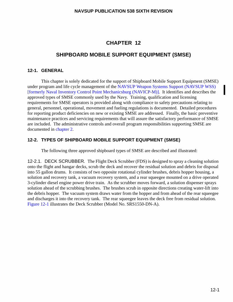
NAVSUP PUBLICATION 538 SIXTH REVISION
12-1
CHAPTER 12
SHIPBOARD MOBILE SUPPORT EQUIPMENT (SMSE)
12-1. GENERAL
This chapter is solely dedicated for the support of Shipboard Mobile Support Equipment (SMSE) under program and life cycle management of the NAVSUP Weapon Systems Support (NAVSUP WSS) [formerly Naval Inventory Control Point Mechanicsburg (NAVICP-M)]. It identifies and describes the approved types of SMSE commonly used by the Navy. Training, qualification and licensing requirements for SMSE operators is provided along with compliance to safety precautions relating to general, personnel, operational, movement and fueling regulations is documented. Detailed procedures for reporting product deficiencies on new or existing SMSE are addressed. Finally, the basic preventive maintenance practices and servicing requirements that will assure the satisfactory performance of SMSE are included. The administrative controls and overall program responsibilities supporting SMSE are documented in chapter 2.
12-2. TYPES OF SHIPBOARD MOBILE SUPPORT EQUIPMENT (SMSE)
The following three approved shipboard types of SMSE are described and illustrated:
12-2.1. DECK SCRUBBER. The Flight Deck Scrubber (FDS) is designed to spray a cleaning solution onto the flight and hangar decks, scrub the deck and recover the residual solution and debris for disposal into 55 gallon drums. It consists of two opposite rotational cylinder brushes, debris hopper housing, a solution and recovery tank, a vacuum recovery system, and a rear squeegee mounted on a drive operated 3-cylinder diesel engine power drive train. As the scrubber moves forward, a solution dispenser sprays solution ahead of the scrubbing brushes. The brushes scrub in opposite directions creating water-lift into the debris hopper. The vacuum system draws water from the hopper and from ahead of the rear squeegee and discharges it into the recovery tank. The rear squeegee leaves the deck free from residual solution. Figure 12-1 illustrates the Deck Scrubber (Model No. SRS1550-DN-A).
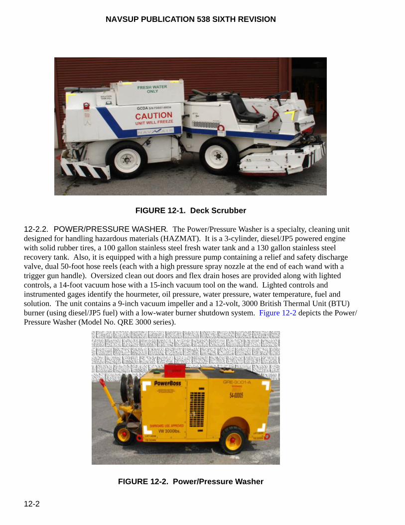
NAVSUP PUBLICATION 538 SIXTH REVISION
12-2
FIGURE 12-1. Deck Scrubber
12-2.2. POWER/PRESSURE WASHER. The Power/Pressure Washer is a specialty, cleaning unit designed for handling hazardous materials (HAZMAT). It is a 3-cylinder, diesel/JP5 powered engine with solid rubber tires, a 100 gallon stainless steel fresh water tank and a 130 gallon stainless steel recovery tank. Also, it is equipped with a high pressure pump containing a relief and safety discharge valve, dual 50-foot hose reels (each with a high pressure spray nozzle at the end of each wand with a trigger gun handle). Oversized clean out doors and flex drain hoses are provided along with lighted controls, a 14-foot vacuum hose with a 15-inch vacuum tool on the wand. Lighted controls and instrumented gages identify the hourmeter, oil pressure, water pressure, water temperature, fuel and solution. The unit contains a 9-inch vacuum impeller and a 12-volt, 3000 British Thermal Unit (BTU) burner (using diesel/JP5 fuel) with a low-water burner shutdown system. Figure 12-2 depicts the Power/Pressure Washer (Model No. QRE 3000 series).
FIGURE 12-2. Power/Pressure Washer

NAVSUP PUBLICATION 538 SIXTH REVISION
12-3
12-2.3. FUEL TRANSFER CART. The Fuel Transfer Cart is used to transfer low flash point fuel to aircraft and fuel cells. It contains a pneumatic pump that retrieves fuel from aircraft or fuel cells and transfers it to either a motor vehicle, to another fuel cell, or to a storage tank. Figure 12-3 provides an example of a Fuel Transfer Cart.
FIGURE 12-3. Fuel Transfer Cart
12-3. LICENSING
12-3.1. DECK SCRUBBER.
12-3.1.1. Qualifications. A license is required for all Deck Scrubber operators. Personnel who comply with the requirements documented in this publication satisfy the qualification requirements to obtain a license to operate the Deck Scrubber.
a. Initial Operator Training. Maintenance Officers (MO’s) are required to ensure that all Deck Scrubber operators have satisfactorily completed the “Deck Scrubber Operator’s Training Course”, appendix F, prior to being issued a license to operate this equipment.
b. Certification. Each student who satisfactorily completes the required operator training described in paragraph 12-3.1.1.a shall be issued the Operator Training Certificate, figure F-1. This certificate shall be completed and retained in each student’s personal file.
c. License. The “MHE Operator’s License”, figure 4-2, shall also serve as the license for Deck Scrubber operators. It is valid for 3 years provided the medical examination certificate has not expired.

NAVSUP PUBLICATION 538 SIXTH REVISION
12-4
The same MHE operator’s licensing requirements documented in paragraph 4-4.1 apply for SMSE Deck Scrubber operators, except the license shall indicate only the following:
(1) All restrictions imposed (e.g., corrective lenses required, daytime operations only, requires hearing aids, etc).
(2) The “Flight Deck Scrubber” field is marked on the “MHE Operator’s License”, figure 4-2.
(3) The Medical Certificate, OPNAV Form 8020/2 (figure 4-1), is either “ON FILE” or “ON PERSON.”
(4) The month and year appears on the “DATE ISSUED” and “DATE EXPIRES” fields.
(5) Only the “Class/Lift Code” column on the “LICENSED TO OPERATE” field is marked with “FDS” as shown in table 4-1. The “SWL” and “Type Designations” columns are left blank.
12-3.2. POWER/PRESSURE WASHER.
12-3.2.1. Qualifications. A license is required for all Power/Pressure Washer operators. Personnel who comply with the requirements documented in this publication satisfy the qualification requirements to obtain a license to operate the QRE-3001A Power/Pressure Washer.
a. Initial Operator Training. Maintenance Officer (MO’s) are required to ensure that all Power/Pressure Washer operators have satisfactorily completed the “QRE-3001A Power/Pressure Washer Operator’s Training Course”, appendix G, prior to being issued a license to operate this equipment.
b. Certification. Each student who satisfactorily completes the required operator training described in paragraph 12-3.2.1a shall be issued the Operator Training Certificate, figure G-1. This certificate shall be completed and retained in each student’s personal life.
c. License. The “MHE Operator License”, figure 4-2, shall also serve as the license for Power/Pressure Washer operators. It is valid for 3 years provided the medical examination certificate has not expired
The same MHE operator’s licensing requirements documented in paragraph 4-4.1 apply for SMSE Power/Pressure Washer operators, except the license shall indicate only the following, required hearing aids, etc)
(1) All restrictions imposed (e.g., corrective license required, daytime operators only, requires hearing aids, etc.).
(2) The “Power/Pressure Washer” field is marked on the “MHE Operator’s License”, figure 4-2.
(3) The Medical Certificate, OPNAV Form 8020/2 (figure 4-1), is either “ON FILE” or “ON PERSON.”
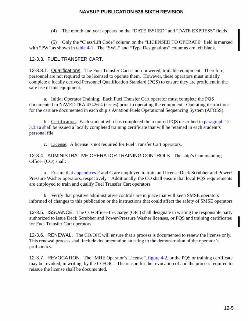
NAVSUP PUBLICATION 538 SIXTH REVISION
12-5
(4) The month and year appears on the “DATE ISSUED” and “DATE EXPRESS” fields.
(5) Only the “Class/Lift Code” column on the “LICENSED TO OPERATE” field is marked with “PW” as shown in table 4-1. The “SWL” and “Type Designations” columns are left blank.
12-3.3. FUEL TRANSFER CART.
12-3.3.1. Qualifications. The Fuel Transfer Cart is non-powered, trailable equipment. Therefore, personnel are not required to be licensed to operate them. However, these operators must initially complete a locally derived Personnel Qualification Standard (PQS) to ensure they are proficient in the safe use of this equipment.
a. Initial Operator Training. Each Fuel Transfer Cart operator must complete the PQS documented in NAVEDTRA 43426-4 (series) prior to operating the equipment. Operating instructions for the cart are documented in each ship’s Aviation Fuels Operational Sequencing System (AFOSS).
b. Certification. Each student who has completed the required PQS described in paragraph 12-3.3.1a shall be issued a locally completed training certificate that will be retained in each student’s personal file.
c. License. A license is not required for Fuel Transfer Cart operators.
12-3.4. ADMINISTRATIVE OPERATOR TRAINING CONTROLS. The ship’s Commanding Officer (CO) shall:
a. Ensure that appendices F and G are employed to train and license Deck Scrubber and Power/Pressure Washer operators, respectively. Additionally, the CO shall ensure that local PQS requirements are employed to train and qualify Fuel Transfer Cart operators.
b. Verify that positive administrative controls are in place that will keep SMSE operators informed of changes to this publication or the instructions that could affect the safety of SMSE operators.
12-3.5. ISSUANCE. The CO/Officer-In-Charge (OIC) shall designate in writing the responsible party authorized to issue Deck Scrubber and Power/Pressure Washer licenses, or PQS and training certificates for Fuel Transfer Cart operators.
12-3.6. RENEWAL. The CO/OIC will ensure that a process is documented to renew the license only. This renewal process shall include documentation attesting to the demonstration of the operator’s proficiency.
12-3.7. REVOCATION. The “MHE Operator’s License”, figure 4-2, or the PQS or training certificate may be revoked, in writing, by the CO/OIC. The reason for the revocation of and the process required to reissue the license shall be documented.
NAVSUP PUBLICATION 538 SIXTH REVISION
12-6
12-4. OPERATIONAL SAFETY REQUIREMENTS
General, personnel and operational safety precautions associated with the use of SMSE is provided. Careless or improper operation of SMSE may result in personnel injury or damage to equipment even if the approved SMSE is used. Therefore, it is imperative that all safety precautions and operator requirements pertaining to the safe operation of SMSE detailing in the following paragraphs are applied and strictly enforced.
12-4.1. DEPARTMENT OF DEFENSE (DOD) OCCUPATIONAL SAFETY AND HEALTH (OSH) PROGRAM. The operations of an effective on-the-job occupational safety and health program is a line management responsibility at all echelons and shall, to the extent of their authority, comply with OSH program guidance and regulations to provide DOD personnel safe and healthful working conditions. This guidance is provided in DODINST 6055.1 (series). Shipboard personnel shall comply with all applicable OSH program regulations documented in OPNAVINST 5100.19 (series). Specifically, this shall include compliance with work safety and health standards, proper use of personal protective equipment (PPE) and clothing, and proper reporting to DOD management of unsafe conditions, hazardous exposure, or occupational injury or illness.
12-4.2. GENERAL SAFETY PRECAUTIONS. It is necessary for the protection of personnel and the safe integrity of the equipment that all safety features show no evidence of damage or deterioration that could cause a hazard to safe equipment operation. Further, each type of SMSE has particular areas that require safety inspections. Therefore, periodic inspections are necessary to determine if any hazards are apparent. In addition to these safety inspections, the deck and working areas must be free of oil or gasoline spots that could cause accidents due to skidding or slipping. All equipment safety devices must be properly installed and maintained. For the Deck Scrubber and Power/Pressure Washer, only qualified and licensed operators may operate the equipment and shall perform the pre-operational and post-operational visual inspections, and functional tests. Lastly, incorrect disposal of HAZMAT is a federal offense. Ensure HAZMAT is disposed of properly in accordance with local disposal procedures.
12-4.2.1. Personnel Safety. The following applicable personnel safety precautions shall be observed:
a. Avoid prolonged contact with, or the inhalation of, cleaning solvents. Avoid use near heat or open flames. Always have adequate ventilation when using cleaning solvents.
b. Do not use flammable or combustible cleaning agents when scrubbing.
c. Corrosion inhibitors can cause damage to the eyes or skin. If contact is made, immediately wash the skin with water. For the eyes, immediately flush the eyes with water for several minutes. In either event, always seek prompt medical attention.
d. A raised scrub head could fall. Always block the scrub head up.
e. Always lock the scrub head up in the raised position when working under the scrub head. Hydraulics alone may “leak down” crushing anything beneath it.
f. The fan suction is very strong. Never run the vacuum fan with the vacuum line removed from the fan or the recovery tank. Keep hands away from the vacuum fan intake.

NAVSUP PUBLICATION 538 SIXTH REVISION
12-7
g. Keep feet and hands away from under the scrub head and when pulling the lever to unlock and lower the debris trough.
h. Keep hands and face from coming in contact with the atomizer spray, as the working pressure will cause the fuel oil to penetrate the skin.
i. All operators shall be familiar with the potential safety hazards associated with the HAZMAT being used with SMSE. As a minimum, the operator must understand the Material Safety Data Sheet (MSDS) and is aware of local HAZMAT regulations involving fire fighting, emergency response and containment/clean-up procedures.
j. Do not check the radiator coolant level when the engine is hot.
12-4.2.2. Operational Safety. The following applicable operational safety precautions shall be observed:
a. Do not operate the starter motor for more than 10 seconds at a time or after the engine has started. Allow the starter to cool between starting attempts. The starter motor may be damaged if it is operated incorrectly.
b. Ensure the scrub head lock has been engaged before leaving the machine.
c. Always engage the parking brake before leaving the machine.
d. Lower the debris trough carefully. Do not allow it to drop.
e. Always stop the engine and engage the parking before operating the vacuum wand. The machine may creep or roll if the brake is not set.
f. Do not overfill the hydraulic fluid reservoir or operate the machine with a low level of hydraulic fluid in the reservoir. Either condition may cause damage to the machine’s hydraulic system.
g. The air pressure nozzle must not exceed 30 pounds psig or 205 (kPa). Always maintain a reasonable distance between the nozzle and the filter.
h. If the engine oil pressure is not present or is lower than the specified value, shut the engine down immediately.
12-4.2.3. Safety Precautions During Movements. When moving SMSE, always operate the equipment with care when driving or moving on wet surfaces.
12-4.2.4. Safety Devices. Several kinds of safety devices have been equipped on the Deck Scrubber by the manufacturer to ensure its safe and efficient operation.

NAVSUP PUBLICATION 538 SIXTH REVISION
12-8
During maintenance operations, safety devices may be removed or disabled but shall be installed or activated immediately upon completion of the scheduled tasks.
12-4.2.4.1. Emergency Fuel Shutoff Switch. An emergency fuel shutoff switch located on the instrument panel of the Deck Scrubber shuts down the engine by stopping the fuel flow. This switch may not be disabled and it shall be properly maintained in accordance with the manufacturer’s instructions.
12-4.2.4.2. Static Discharge Device. The Deck Scrubber is equipped with an electrical conductive ground strap which allows any static charge to be safely discharged to the deck. The strap shall always be installed on the unit and must always contact the deck.
12-4.2.4.3. Scrub Head Lock Lever. A scrub head lock lever is equipped on the Deck Scrubber located on the floor near the operator’s left foot which prevents the scrub head from lowering during maintenance operations. To prevent injuries to maintenance personnel, this lever must be engaged prior to any scheduled tasks.
12-4.2.5. Safety During Fueling. The safety precautions during fueling described in paragraph 5-5 also apply for the Deck Scrubber or the Power/Pressure Washer.
12-5. COLOR
All Navy-owned SMSE shall be painted as follows:
a. Deck Scrubber. All Deck Scrubbers shall be primed with light gray epoxy conforming to MIL-P-0053022 (replaces MIL-P-53022) and shall be painted yellow in accordance with FED-STD-595, Color No. 13538.
b. Pressure/Power Washer. All Pressure/Power Washers shall be primed with light gray epoxy conforming to MIL-P-0053022 (replaces MIL-P-53022) and shall be painted yellow in accordance with FED-STD-595, Color No. 13538.
c. Fuel Transfer Cart. Fuel Transfer Cart components (i.e., piping) may be painted gloss purple in accordance with FED-STD-595, Color No. 17142 or 17155 to designate it as jet fuel within the equipment.
12-6. MARKINGS
The following markings are required for all shipboard Pressure/Power Washers. There is no specific safety markings associated with the Deck Scrubber or Fuel Transfer Cart. However, when any SMSE is scheduled for a complete paint overhaul, all markings originally provided by the manufacturer must be replaced on the equipment.
WARNING
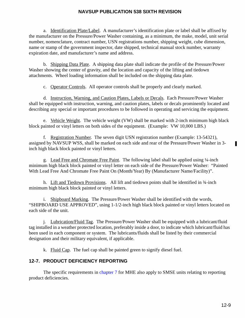
NAVSUP PUBLICATION 538 SIXTH REVISION
12-9
a. Identification Plate/Label. A manufacturer’s identification plate or label shall be affixed by the manufacturer on the Pressure/Power Washer containing, as a minimum, the make, model, unit serial number, nomenclature, contract number, USN registrations number, shipping weight, cube dimension, name or stamp of the government inspector, date shipped, technical manual stock number, warranty expiration date, and manufacturer’s name and address.
b. Shipping Data Plate. A shipping data plate shall indicate the profile of the Pressure/Power Washer showing the center of gravity, and the location and capacity of the lifting and tiedown attachments. Wheel loading information shall be included on the shipping data plate.
c. Operator Controls. All operator controls shall be properly and clearly marked.
d. Instruction, Warning, and Caution Plates, Labels or Decals. Each Pressure/Power Washer shall be equipped with instruction, warning, and caution plates, labels or decals prominently located and describing any special or important procedures to be followed in operating and servicing the equipment.
e. Vehicle Weight. The vehicle weight (VW) shall be marked with 2-inch minimum high black block painted or vinyl letters on both sides of the equipment. (Example: VW 10,000 LBS.)
f. Registration Number. The seven digit USN registration number (Example: 13-54321), assigned by NAVSUP WSS, shall be marked on each side and rear of the Pressure/Power Washer in 3-inch high black block painted or vinyl letters.
g. Lead Free and Chromate Free Paint. The following label shall be applied using ¼-inch minimum high black block painted or vinyl letter on each side of the Pressure/Power Washer: “Painted With Lead Free And Chromate Free Paint On (Month/Year) By (Manufacturer Name/Facility)”.
h. Lift and Tiedown Provisions. All lift and tiedown points shall be identified in ¾-inch minimum high black block painted or vinyl letters.
i. Shipboard Marking. The Pressure/Power Washer shall be identified with the words, “SHIPBOARD USE APPROVED”, using 1-1/2-inch high black block painted or vinyl letters located on each side of the unit.
j. Lubrication/Fluid Tag. The Pressure/Power Washer shall be equipped with a lubricant/fluid tag installed in a weather protected location, preferably inside a door, to indicate which lubricant/fluid has been used in each component or system. The lubricants/fluids shall be listed by their commercial designation and their military equivalent, if applicable.
k. Fluid Cap. The fuel cap shall be painted green to signify diesel fuel.
12-7. PRODUCT DEFICIENCY REPORTING
The specific requirements in chapter 7 for MHE also apply to SMSE units relating to reporting product deficiencies.

NAVSUP PUBLICATION 538 SIXTH REVISION
12-10
12-8. PREVENTIVE MAINTENANCE
The following requirements provide the basic preventive maintenance practices and periodic servicing requirements that will assure the satisfactory performance of SMSE. For specific preventive maintenance, corrective maintenance, scheduled lubrication and inspection of specific safety devices, reference should also be made to the manufacturer’s technical manual that is supplied with the equipment or using the applicable Maintenance Index Page (MIP) and their associated Maintenance Requirements Cards (MRC’s). Consult the latest shipboard (electronic version) of the Force Revision for the most current available MIP and their associated MRCs.
12-8.1. RESPONSIBILITIES. Preventive maintenance and support funding is the direct responsibility of the SMSE holder of record and the indirect responsibility of personnel who operate SMSE. For this reason, all personnel who operate SMSE must satisfy the operator qualification requirements described in paragraph 12-3.1.1. Likewise, maintenance and inspection on all SMSE shall be performed in conformance with the following practices:
a. A scheduled planned maintenance, lubrication and inspection system [e.g., Equipment Management and Control System (EMACS), Maintenance Material Management (3M) Manual, MIP’s with their associated MRC’s, etc.] shall be followed. Consult the manufacturer’s recommendations as well.
b. Only trained, knowledgeable or experienced personnel shall be authorized to maintain, repair, adjust and inspect SMSE in accordance with the manufacturer’s specifications or the MIP/MRC’s.
12-8.1.1. Operator Responsibilities. SMSE operators shall perform pre-operational and post-operational visual inspections and functional tests in accordance with MIP 5882/013 for the Deck Scrubber, MIP 5882/014 for the Power/Pressure Washer, or MIP 5420/008 for the Fuel Transfer Cart prior to placing the equipment in service and upon completion of the daily operation. All operators shall record all defects, notify the immediate supervisor of defects, and tag-out the unserviceable SMSE for repairs in accordance with local procedures. As a minimum, all local procedures established shall stipulate the following:
a. A safety deficiency tag-out process, which includes procedures for tagging [e.g., “DO NOT OPERATE” tag (NAVSUP Form 1377/6), figure 8-6, red tag, caution, etc.] unserviceable SMSE in a conspicuous location and for removing equipment from service until repairs are made.
b. All defects found and repairs/servicing accomplished shall be documented in the equipment history file.
12-8.1.2. Maintenance Provider Responsibilities. When SMSE is scheduled for preventive maintenance servicing every 18 and 36 months, it should be cleaned prior to receiving an inspection by authorized personnel. Upon completion of the preliminary servicing, a thorough inspection of the equipment, including an operational test and service inspection, shall be conducted. Preliminary servicing and inspections should be accomplished in accordance with EMACS, the 3M System (MIP/MRC’s), the applicable manufacturer’s technical manual, or local equivalent procedures, which authorizes minor adjustments to the equipment. If, however, the inspection indicates major adjustments
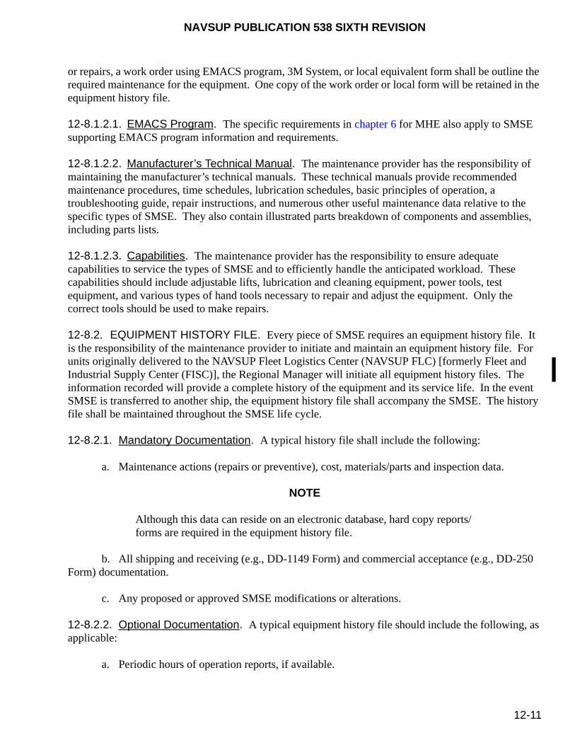
NAVSUP PUBLICATION 538 SIXTH REVISION
12-11
or repairs, a work order using EMACS program, 3M System, or local equivalent form shall be outline the required maintenance for the equipment. One copy of the work order or local form will be retained in the equipment history file.
12-8.1.2.1. EMACS Program. The specific requirements in chapter 6 for MHE also apply to SMSE supporting EMACS program information and requirements.
12-8.1.2.2. Manufacturer’s Technical Manual. The maintenance provider has the responsibility of maintaining the manufacturer’s technical manuals. These technical manuals provide recommended maintenance procedures, time schedules, lubrication schedules, basic principles of operation, a troubleshooting guide, repair instructions, and numerous other useful maintenance data relative to the specific types of SMSE. They also contain illustrated parts breakdown of components and assemblies, including parts lists.
12-8.1.2.3. Capabilities. The maintenance provider has the responsibility to ensure adequate capabilities to service the types of SMSE and to efficiently handle the anticipated workload. These capabilities should include adjustable lifts, lubrication and cleaning equipment, power tools, test equipment, and various types of hand tools necessary to repair and adjust the equipment. Only the correct tools should be used to make repairs.
12-8.2. EQUIPMENT HISTORY FILE. Every piece of SMSE requires an equipment history file. It is the responsibility of the maintenance provider to initiate and maintain an equipment history file. For units originally delivered to the NAVSUP Fleet Logistics Center (NAVSUP FLC) [formerly Fleet and Industrial Supply Center (FISC)], the Regional Manager will initiate all equipment history files. The information recorded will provide a complete history of the equipment and its service life. In the event SMSE is transferred to another ship, the equipment history file shall accompany the SMSE. The history file shall be maintained throughout the SMSE life cycle.
12-8.2.1. Mandatory Documentation. A typical history file shall include the following:
a. Maintenance actions (repairs or preventive), cost, materials/parts and inspection data.
NOTE
Although this data can reside on an electronic database, hard copy reports/forms are required in the equipment history file.
b. All shipping and receiving (e.g., DD-1149 Form) and commercial acceptance (e.g., DD-250 Form) documentation.
c. Any proposed or approved SMSE modifications or alterations.
12-8.2.2. Optional Documentation. A typical equipment history file should include the following, as applicable:
a. Periodic hours of operation reports, if available.
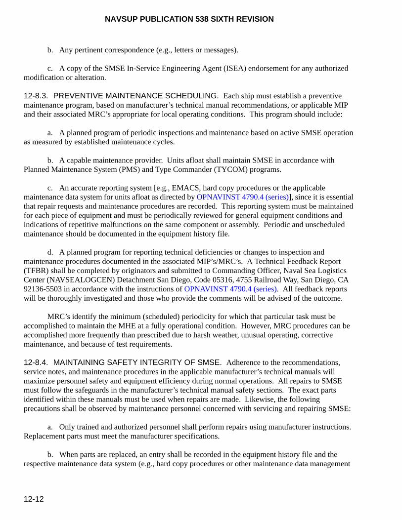
NAVSUP PUBLICATION 538 SIXTH REVISION
12-12
b. Any pertinent correspondence (e.g., letters or messages).
c. A copy of the SMSE In-Service Engineering Agent (ISEA) endorsement for any authorized modification or alteration.
12-8.3. PREVENTIVE MAINTENANCE SCHEDULING. Each ship must establish a preventive maintenance program, based on manufacturer’s technical manual recommendations, or applicable MIP and their associated MRC’s appropriate for local operating conditions. This program should include:
a. A planned program of periodic inspections and maintenance based on active SMSE operation as measured by established maintenance cycles.
b. A capable maintenance provider. Units afloat shall maintain SMSE in accordance with Planned Maintenance System (PMS) and Type Commander (TYCOM) programs.
c. An accurate reporting system [e.g., EMACS, hard copy procedures or the applicable maintenance data system for units afloat as directed by OPNAVINST 4790.4 (series)], since it is essential that repair requests and maintenance procedures are recorded. This reporting system must be maintained for each piece of equipment and must be periodically reviewed for general equipment conditions and indications of repetitive malfunctions on the same component or assembly. Periodic and unscheduled maintenance should be documented in the equipment history file.
d. A planned program for reporting technical deficiencies or changes to inspection and maintenance procedures documented in the associated MIP’s/MRC’s. A Technical Feedback Report (TFBR) shall be completed by originators and submitted to Commanding Officer, Naval Sea Logistics Center (NAVSEALOGCEN) Detachment San Diego, Code 05316, 4755 Railroad Way, San Diego, CA 92136-5503 in accordance with the instructions of OPNAVINST 4790.4 (series). All feedback reports will be thoroughly investigated and those who provide the comments will be advised of the outcome.
MRC’s identify the minimum (scheduled) periodicity for which that particular task must be accomplished to maintain the MHE at a fully operational condition. However, MRC procedures can be accomplished more frequently than prescribed due to harsh weather, unusual operating, corrective maintenance, and because of test requirements.
12-8.4. MAINTAINING SAFETY INTEGRITY OF SMSE. Adherence to the recommendations, service notes, and maintenance procedures in the applicable manufacturer’s technical manuals will maximize personnel safety and equipment efficiency during normal operations. All repairs to SMSE must follow the safeguards in the manufacturer’s technical manual safety sections. The exact parts identified within these manuals must be used when repairs are made. Likewise, the following precautions shall be observed by maintenance personnel concerned with servicing and repairing SMSE:
a. Only trained and authorized personnel shall perform repairs using manufacturer instructions. Replacement parts must meet the manufacturer specifications.
b. When parts are replaced, an entry shall be recorded in the equipment history file and the respective maintenance data system (e.g., hard copy procedures or other maintenance data management
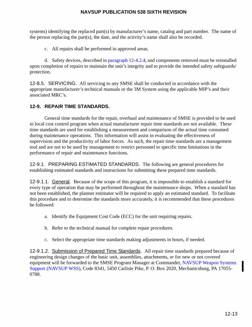
NAVSUP PUBLICATION 538 SIXTH REVISION
12-13
systems) identifying the replaced part(s) by manufacturer’s name, catalog and part number. The name of the person replacing the part(s), the date, and the activity’s name shall also be recorded.
c. All repairs shall be performed in approved areas.
d. Safety devices, described in paragraph 12-4.2.4, and components removed must be reinstalled upon completion of repairs to maintain the unit’s integrity and to provide the intended safety safeguards/protection.
12-8.5. SERVICING. All servicing to any SMSE shall be conducted in accordance with the appropriate manufacturer’s technical manuals or the 3M System using the applicable MIP’s and their associated MRC’s.
12-9. REPAIR TIME STANDARDS.
General time standards for the repair, overhaul and maintenance of SMSE is provided to be used in local cost control program when actual manufacturer repair time standards are not available. These time standards are used for establishing a measurement and comparison of the actual time consumed during maintenance operations. This information will assist in evaluating the effectiveness of supervision and the productivity of labor forces. As such, the repair time standards are a management tool and are not to be used by management to restrict personnel to specific time limitations in the performance of repair and maintenance functions.
12-9.1. PREPARING ESTIMATED STANDARDS. The following are general procedures for establishing estimated standards and instructions for submitting these prepared time standards.
12-9.1.1. General. Because of the scope of this program, it is impossible to establish a standard for every type of operation that may be performed throughout the maintenance shops. When a standard has not been established, the planner estimator will be required to apply an estimated standard. To facilitate this procedure and to determine the standards more accurately, it is recommended that these procedures be followed:
a. Identify the Equipment Cost Code (ECC) for the unit requiring repairs.
b. Refer to the technical manual for complete repair procedures.
c. Select the appropriate time standards making adjustments in hours, if needed.
12-9.1.2. Submission of Prepared Time Standards. All repair time standards prepared because of engineering design changes of the basic unit, assemblies, attachments, or for new or not covered equipment will be forwarded to the SMSE Program Manager at Commander, NAVSUP Weapon Systems Support (NAVSUP WSS), Code 8341, 5450 Carlisle Pike, P. O. Box 2020, Mechanicsburg, PA 17055-0788.
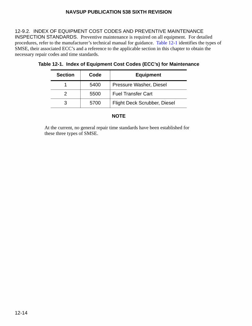
NAVSUP PUBLICATION 538 SIXTH REVISION
12-14
12-9.2. INDEX OF EQUIPMENT COST CODES AND PREVENTIVE MAINTENANCE INSPECTION STANDARDS. Preventive maintenance is required on all equipment. For detailed procedures, refer to the manufacturer’s technical manual for guidance. Table 12-1 identifies the types of SMSE, their associated ECC’s and a reference to the applicable section in this chapter to obtain the necessary repair codes and time standards.
NOTE
At the current, no general repair time standards have been established for these three types of SMSE.
Table 12-1. Index of Equipment Cost Codes (ECC’s) for Maintenance
Section Code Equipment
1 5400 Pressure Washer, Diesel
2 5500 Fuel Transfer Cart
3 5700 Flight Deck Scrubber, Diesel
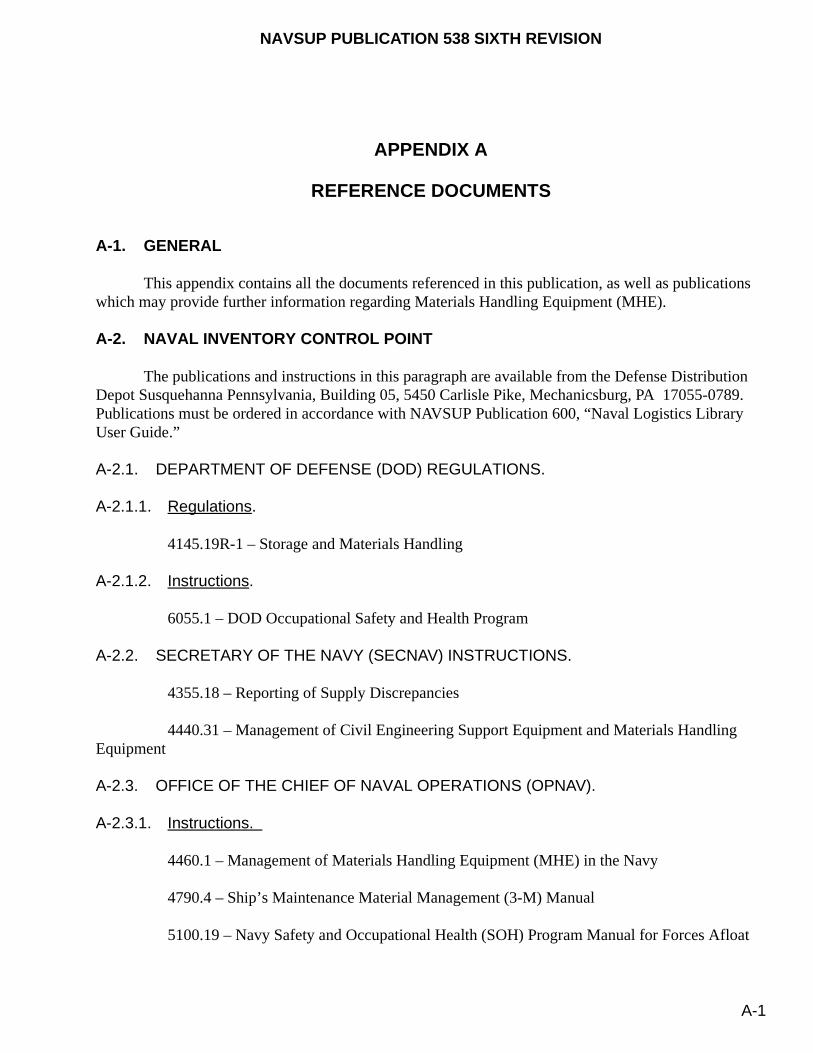
NAVSUP PUBLICATION 538 SIXTH REVISION
A-1
APPENDIX A
REFERENCE DOCUMENTS
A-1. GENERAL
This appendix contains all the documents referenced in this publication, as well as publications which may provide further information regarding Materials Handling Equipment (MHE).
A-2. NAVAL INVENTORY CONTROL POINT
The publications and instructions in this paragraph are available from the Defense Distribution Depot Susquehanna Pennsylvania, Building 05, 5450 Carlisle Pike, Mechanicsburg, PA 17055-0789. Publications must be ordered in accordance with NAVSUP Publication 600, “Naval Logistics Library User Guide.”
A-2.1. DEPARTMENT OF DEFENSE (DOD) REGULATIONS.
A-2.1.1. Regulations.
4145.19R-1 – Storage and Materials Handling
A-2.1.2. Instructions.
6055.1 – DOD Occupational Safety and Health Program
A-2.2. SECRETARY OF THE NAVY (SECNAV) INSTRUCTIONS.
4355.18 – Reporting of Supply Discrepancies
4440.31 – Management of Civil Engineering Support Equipment and Materials Handling Equipment
A-2.3. OFFICE OF THE CHIEF OF NAVAL OPERATIONS (OPNAV).
A-2.3.1. Instructions.
4460.1 – Management of Materials Handling Equipment (MHE) in the Navy
4790.4 – Ship’s Maintenance Material Management (3-M) Manual
5100.19 – Navy Safety and Occupational Health (SOH) Program Manual for Forces Afloat

NAVSUP PUBLICATION 538 SIXTH REVISION
A-2
5100.23 – Navy Safety and Occupational Health (SOH) Program Manual for Shore Activities
5100.28 – Hazardous Material User’s Guide (HMUG) (Shipboard)
8020.14 – Department of the Navy Explosives Safety Policy Manual
A-2.3.2. Publications.
A-2.4. COMMANDER NAVAL AIR FORCE (COMNAVAIRFOR).
A-2.4.1. COMNAVAIRFOR Instructions (COMNAVAIRFORINST).
4790.2 – Naval Aviation Maintenance Program (NAMP) (formerly OPNAVINST 4790.2)
A-2.5. NAVAL AIR SYSTEMS COMMAND (NAVAIRSYSCOM).
A-2.5.1. NAVAIR Publications.
00-80R-19 – NATOPS U.S. Navy Aircraft Crash and Salvage Operations Manual (Afloat)
A-2.6. NAVAL EDUCATION TRAINING (NAVEDTRA).
A-2.6.1. NAVEDTRA Courses.
43426-4 – Personnel Qualification Standards (PQS) for Air Department Aviation Fuels Afloat
A-2.7. NAVAL FACILITIES ENGINEERING COMMAND (NAVFACENGCOM) PUBLICATIONS.
P-300 – Management of Civil Engineering Support Equipment
P-307 – Management of Weight Handling Equipment; Maintenance and Certification
A-2.8. NAVSUP WEAPON SYSTEM SUPPORT (NAVSUP WSS)[FORMERLY NAVAL INVENTORY CONTROL POINT (NAVICP)] INSTRUCTIONS (NAVSUP WSS INST).
A-2.8.1. Instructions.
10490.4 – Materials Handling Equipment (MHE); Administration and Control of
A-2.8.2. Specifications [Commercial Item Descriptions (CID’s) and Shipboard Purchase Descriptions (PD’s)].
CID-A-A-59405, Type 1 - 4K Forklift, Electric (EE) (ECC 1372)
CID-A-A-59405, Type 2 - 6K Forklift, Electric (EE) (ECC 1372)

NAVSUP PUBLICATION 538 SIXTH REVISION
A-3
CID-A-A-59405, Type 3 - 4K Forklift, Electric (EX) (ECC 1380)
CID-A-A-59492, Type I - 6K Forklift, Diesel, RT (ECC 1820)
CID-A-A-59492, Type II - 10K Forklift, Diesel, RT 24’ LC (ECC 1820)
CID-A-A-59492, Type III - 10K Forklift, Diesel, RT 48’ LC (ECC 1820)
CID-A-A-59493, Type 2 - 4K Forklift, Reach & Tier (ECC 1390)
CID-A-A-59498, Type 4 - 4.5K Forklift, Reach & Tier (ECC 1390)
CID-A-A-59498, Type 2 - 6K Forklift, Diesel, Low-Profile (ECC 1351)
CID-A-A-59498, Type 4 - 15K Forklift, Diesel (ECC 1340)
CID-A-A-59498, Type 5 - 20K Forklift, Diesel (ECC 1340)
PD-500 - 4K Forklift, Diesel, RT (ECC 1820)
PD-1610 - 6K Pallet, Electric, Walkie (ECC 1610)
PD-1900 - 6K Pallet, Manual, Hydraulic (ECC 1900)
PD-9901 - 6K Forklift, Diesel (ECC 1350)
PD-73008 - SRS 1550 Flight Deck Scrubber (ECC 5700)
PD-013110 - Aerial Work Platforms, Telescopic Boom (ECC 1396) [Supersedes PD-80106 and PD-80806]
Power-Boss QRE-3001A - Pressure Washer (ECFC 5400)
A-2.9. NAVAL ORDNANCE SAFETY AND SECURITY ACTIVITY (NOSSA) INSTRUCTIONS (NOSSAINST).
8023.11 – Standard Operating Procedures (SOPs): Development, Implementation and Maintenance for Ammunition and Explosives
A-2.10. NAVAL SEA SYSTEMS COMMAND (NAVSEASYSCOM).
A-2.10.1. NAVSEA Instructions (NAVSEAINST).
8020.9 – Non-Nuclear Ordnance and Explosives Handling Qualification and Certification Program

NAVSUP PUBLICATION 538 SIXTH REVISION
A-4
8023.11 – Standard Operating Procedures (SOPs) for the Processing of Expendable Ordnance at Navy and Marine Corps Activities
A-2.10.2. NAVSEA Ordnance Pamphlets (OP).
4 – Ammunition and Explosives Safety Afloat
5 Volume 1 – Ammunition and Explosives Safety Ashore
2173 – Approved Handling Equipment for Weapons and Explosives (2 volumes)
A-2.10.3. NAVSEA Technical Manuals.
SG420-AP-MMA-010 – Periodic Testing Arrangements for Ordnance Handling Equipment
SW023-AH-WHM-010 – Handling Ammunition and Explosives With Industrial Materials Handling Equipment (MHE)
A-2.11. NAVAL SUPPLY SYSTEMS COMMAND (NAVSUPSYSCOM).
A-2.11.1. NAVSUP Instructions (NAVSUPINST).
4440.179 – Report of Discrepancy (ROD) Manual; Exchange of Non-Excess Personal Property of the Navy
4610.33 – Reporting of Transportation Discrepancies in Shipment
10490.33 – Materials Handling Equipment (MHE); Administration and Control of (formerly SPCCINST’s 10490.2 and 10490.3)
A-2.11.2. NAVSUP Publications (NAVSUP PUB).
717 – Naval War Reserve Material Requirements
284 – Storage and Materials Handling
572 – Joint Service Manual (JSM) for Storage and Materials Handling
573 – Storage and Handling of Hazardous Materials
600 – Naval Logistics Library User Guide
723 – Navy Inventory Integrity Procedures
724 – Conventional Ordnance Management; Policies and Procedures
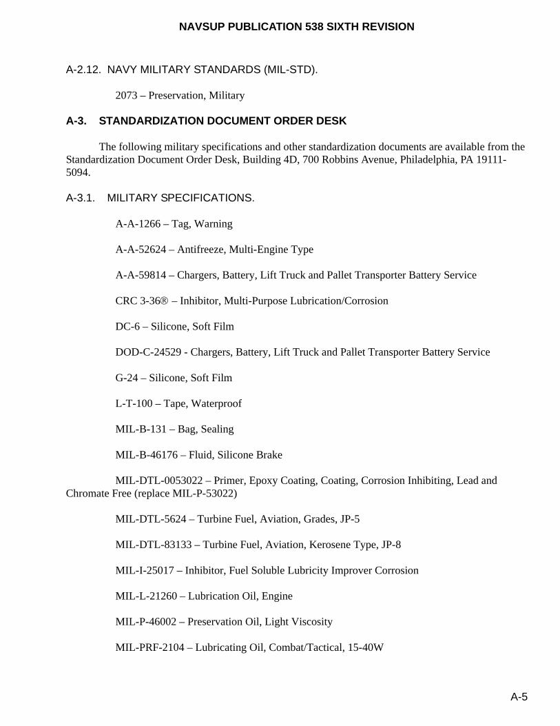
NAVSUP PUBLICATION 538 SIXTH REVISION
A-5
A-2.12. NAVY MILITARY STANDARDS (MIL-STD).
2073 – Preservation, Military
A-3. STANDARDIZATION DOCUMENT ORDER DESK
The following military specifications and other standardization documents are available from the Standardization Document Order Desk, Building 4D, 700 Robbins Avenue, Philadelphia, PA 19111-5094.
A-3.1. MILITARY SPECIFICATIONS.
A-A-1266 – Tag, Warning
A-A-52624 – Antifreeze, Multi-Engine Type
A-A-59814 – Chargers, Battery, Lift Truck and Pallet Transporter Battery Service
CRC 3-36 – Inhibitor, Multi-Purpose Lubrication/Corrosion
DC-6 – Silicone, Soft Film
DOD-C-24529 - Chargers, Battery, Lift Truck and Pallet Transporter Battery Service
G-24 – Silicone, Soft Film
L-T-100 – Tape, Waterproof
MIL-B-131 – Bag, Sealing
MIL-B-46176 – Fluid, Silicone Brake
MIL-DTL-0053022 – Primer, Epoxy Coating, Coating, Corrosion Inhibiting, Lead and Chromate Free (replace MIL-P-53022)
MIL-DTL-5624 – Turbine Fuel, Aviation, Grades, JP-5
MIL-DTL-83133 – Turbine Fuel, Aviation, Kerosene Type, JP-8
MIL-I-25017 – Inhibitor, Fuel Soluble Lubricity Improver Corrosion
MIL-L-21260 – Lubrication Oil, Engine
MIL-P-46002 – Preservation Oil, Light Viscosity
MIL-PRF-2104 – Lubricating Oil, Combat/Tactical, 15-40W

NAVSUP PUBLICATION 538 SIXTH REVISION
A-6
MIL-PRF-17672 – Hydraulic Fluid, Petroleum, Inhibited
MIL-PRF-23827 – Grease, Aircraft and Instrument, Gear and Actuator Screw (formerly MIL-G-23827)
MIL-PRF-26915 – Primer Coating for Steel Surfaces
MIL-T-46755 – Bags/Covers, Polyethylene, Protective
O-E-760 – Alcohol, Denatured Ethyl
P-C-437 – Compound Cleaning
PD-680 – Solvent, Dry Cleaning
VV-B-680 – Fluid, Brake
A-3.2. FEDERAL STANDARDS (FED-STD).
595 – Colors Used in Government Procurement
A-4. MARINE CORPS ORDERS (MCO)
Requests for Marine Corps publications should be directed to CMC (HQSP-2), Washington, DC 20380, and should be submitted in accordance with the current edition of MCO P5600.31. Additionally, an index of Marine Corps publications is available at http://www.marines.mil/news/publications/Pages/default.aspx.
3571.2 – Explosive Ordnance Disposal (EOD) Program
P8020.11 – Department of the Navy Explosives Safety Policy Manual
P11262.2 - Inspection, Testing and Certification of Tactical Ground Load Lifting Equipment
A-5. SUPERINTENDENT OF DOCUMENTS
The following publications are available from the Superintendent of Documents, U.S. Government Printing Office, Washington, D.C. 20402 or visit their web site at http://www.dot.gov/.
CODE OF FEDERAL REGULATIONS (CFR).
29 CFR 1910 – Occupational Safety and Health Standards
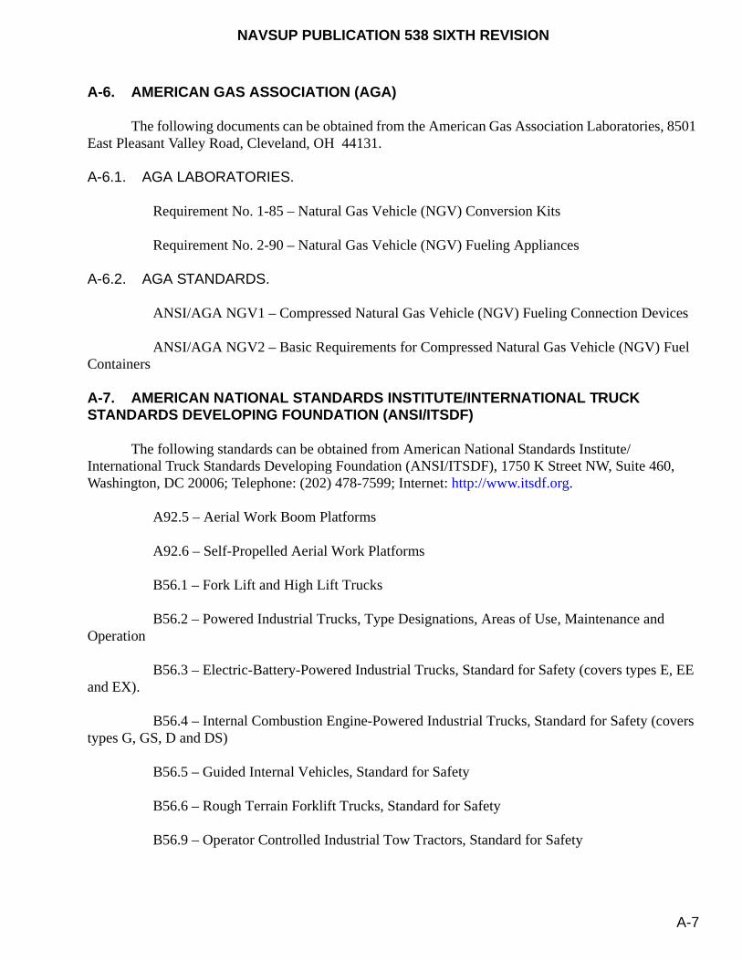
NAVSUP PUBLICATION 538 SIXTH REVISION
A-7
A-6. AMERICAN GAS ASSOCIATION (AGA)
The following documents can be obtained from the American Gas Association Laboratories, 8501 East Pleasant Valley Road, Cleveland, OH 44131.
A-6.1. AGA LABORATORIES.
Requirement No. 1-85 – Natural Gas Vehicle (NGV) Conversion Kits
Requirement No. 2-90 – Natural Gas Vehicle (NGV) Fueling Appliances
A-6.2. AGA STANDARDS.
ANSI/AGA NGV1 – Compressed Natural Gas Vehicle (NGV) Fueling Connection Devices
ANSI/AGA NGV2 – Basic Requirements for Compressed Natural Gas Vehicle (NGV) Fuel Containers
A-7. AMERICAN NATIONAL STANDARDS INSTITUTE/INTERNATIONAL TRUCK STANDARDS DEVELOPING FOUNDATION (ANSI/ITSDF)
The following standards can be obtained from American National Standards Institute/International Truck Standards Developing Foundation (ANSI/ITSDF), 1750 K Street NW, Suite 460, Washington, DC 20006; Telephone: (202) 478-7599; Internet: http://www.itsdf.org.
A92.5 – Aerial Work Boom Platforms
A92.6 – Self-Propelled Aerial Work Platforms
B56.1 – Fork Lift and High Lift Trucks
B56.2 – Powered Industrial Trucks, Type Designations, Areas of Use, Maintenance and Operation
B56.3 – Electric-Battery-Powered Industrial Trucks, Standard for Safety (covers types E, EE and EX).
B56.4 – Internal Combustion Engine-Powered Industrial Trucks, Standard for Safety (covers types G, GS, D and DS)
B56.5 – Guided Internal Vehicles, Standard for Safety
B56.6 – Rough Terrain Forklift Trucks, Standard for Safety
B56.9 – Operator Controlled Industrial Tow Tractors, Standard for Safety
NAVSUP PUBLICATION 538 SIXTH REVISION
A-8
Z9.2 – Fundaments Governing the Design and Operation of Local Exhaust Systems
Z9.3 – Safety Code for Design, Construction and Ventilation of Spray Finishing Operations
Z41 – Personnel Protection – Protective Footwear
Z87.1 – Practice for Occupational and Educational Eye and Face Protection
Z88.1 – Practices for Respiratory Protection
Z89.1 – Personnel Protection – Protective
Z358.1 – American National Standard for Emergency Eyewash and Shower Equipment
A-8. COASTAL TRAINING TECHNOLOGIES CORPORATION
The following MHE training videos can be obtained from the Coastal Training Technologies Corporation, 500 Studio Drive, Virginia Beach, VA 23452; Telephone: (757) 498-9014; Internet: http://www.training.dupont.com/training-materials
Forklift Basics – Safe From The Start (23 minutes)
Forklift Fundamentals – Get The Facts
Forklift Maneuvers – All The Right Moves (26 minutes)
Forklift Operations – Carry The Load
A-9. COMPRESSED GAS ASSOCIATION (CGA)
The following standards can be obtained from the Compressed Gas Association, Inc., 1725 Jefferson Davis Highway, Suite 1004, Arlington, VA 22202-4102.
CGA C-6 – Standards for Visual Inspection of Steel Compressed Gas Cylinders
CGA C-6.1 – Standards for Visual Inspection of High Pressure Aluminum Compressed Gas Cylinders
CGA C-6.2 – Guidelines for Visual Inspection and Re-qualification of Fiber Reinforced High Pressure Cylinders
A-10. NATIONAL FIRE PROTECTION AGENCY (NFPA)
The following documents can be obtained from the National Fire Protection Agency, Batterymarch Park, Quincy, MA 02269.

NAVSUP PUBLICATION 538 SIXTH REVISION
A-9
10 – Portable Extinguishers
30 – Flammable and Combustible Liquids Code
33 – Spray Finishing
45 – Fire Protection for Laboratories Using Chemicals
52 – Compressed Natural Gas (CNG) Vehicular Fuel Systems
58 – Standard for the Storage and Handling of Liquefied Petroleum Gases
70 – National Electrical Code
80 – Fire Doors and Windows
91 – Standard for the Installation of Blower and Exhaust Systems for Dust, Stock, and Vapor Removal or Conveying
101 – Life Safety Code
325 – Fire Hazard Properties of Flammable Liquids, Gases and Volatile Solids
430 – Code for the Storage of Liquid and Solid Oxidizers
505 – Fire Safety Standard for Powered Industrial Trucks, Including Type Designations, Areas of Use, Maintenance and Operation
A-11. NATIONAL PROPANE GAS ASSOCIATION (NPGA)
The following bulletins can be obtained from the National Propane Gas Association, 1600 Eisenhower Lane, Suite 100, Lisle, IL 60532.
C602 – Safe Use of LP-Gas in Industrial Trucks
C611 – Recommended Safe Filling Procedures for Forklift Fuel Cylinders (Containers)
0055 – Refueling LP-Gas Powered Vehicles Safety
A-12. SERVICE LIFE EXTENSION PROGRAM (SLEP) TECHNICAL MEMORANDUM
The following technical memorandum is available from Director, Naval Surface Warfare Center, Indian Head Division Detachment Picatinny, Naval PHST Center (Code G1), Building 458, Whittemore Avenue, Picatinny Arsenal, NJ 07806-5000.
PHST-35-00 – MHE Service Life Extension Program (SLEP); Processing Guide

NAVSUP PUBLICATION 538 SIXTH REVISION
A-10
A-13. SOCIETY OF AUTOMOTIVE ENGINEERS (SAE)
The following specification is available from the Society of Automotive Engineers, 400 Commonwealth Drive, Warrendale, PA 15096-0001; Telephone: (724) 776-4841.
J2360 – Lubricating Oil, Gear Multipurpose (Metric) Use (replaces MIL-PRF-2105)
A-14. UNDERWRITERS’ LABORATORY (UL)
The following standards are available from Underwriters’ Laboratories, 333 Pfingsten Road, Northbrook, IL 60062.
558 – Industrial Trucks, Internal Combustion Engine Powered
583 – Electric-Battery Powered Industrial Trucks

NAVSUP PUBLICATION 538 SIXTH REVISION
B-1
APPENDIX B
MATERIALS HANDLING EQUIPMENT OPERATOR TRAINING COURSE
B-1. PURPOSE
This training course establishes the minimum requirements that U.S. Navy personnel must successfully meet prior to being issued a powered industrial materials handling equipment (MHE) license to handle general supply materials (general cargo or stores) and hazardous materials (HAZMAT) other than ammunition and explosives. Refer to NAVSEA SW023-AH-WHM-010 for powered MHE operator licensing requirements when handling ammunition and explosives.
B-2. SCOPE
This course identifies the various types of MHE approved afloat and ashore, defines the operational areas in which the MHE can be operated, addresses operational safety precautions, and concludes with a test that assesses the students knowledge of safety requirements and operational proficiency. Upon satisfactorily completing this course and the medical qualification requirements found in paragraph 4-3.1, students may be issued a license under the provisions of paragraph 4-4 for handling general supply materials. For the handling of HAZMAT, MHE operators will be required to satisfactorily complete any local training requirements as described in paragraph 4-3.6.
B-3. COURSE VARIATIONS
Commanders, Commanding Officers or Officers-in-Charge (CO/OIC), at their discretion and under their documented approval, may authorize variations as needed to adopt this course to train and license MHE operators.
B-4. CONTENT AND DURATION
MHE operators are trained to a competency level, not a defined number of hours. The number of hours identified for the entire course and each lesson are for scheduling purposes only and may be shorter or longer depending on the students abilities. Given a class size of 2 to 10 students with different experience levels, it takes 8 hours of classroom time to cover the various types of MHE, transportation and storage requirements, operating and reporting requirements, mandatory inspection requirements, bulk storage, operation in confined areas, and the handling of various size loads. The classroom time occurs on the first day and is enforced throughout the week during the practical exercises. Past experience indicates that 24 hours are required for practical exercises covering flatbed, trailer, railcar, ramp, dock and magazine handling operations. These hours are broken down as follows: 8 hours of basic operating and lifting techniques, 4 hours of handling bulk items, 4 hours of maneuvering in confined areas, and 8 hours of handling different size loads. The final 8 hours is a proficiency test consisting of a written test and an operational skills demonstration.
NAVSUP PUBLICATION 538 SIXTH REVISION
B-2
B-4.1. MODIFICATIONS. It is not possible for this course to cover every training scenario for all types of MHE in use, the operational environments encountered, and the abilities of the individual students. For these reasons, satisfactory completion of the classroom material is mandatory and instructors are permitted to modify the practical exercises to accommodate the MHE used and the operational environments encountered at each activity. For example, to issue a license to an individual to operate a 6,000-pound DS Rough Terrain Forklift Truck, the instructor would eliminate operational areas that it would not be used in (a railcar, trailer, etc.) and have the practical exercises performed in appropriate rough terrain (steep ramps) conditions.
B-5. TRANSFER OF COMMAND
If this same MHE operator is subsequently transferred to another activity that has only 4,000-pound EE Reaching/Tiering and 6,000-pound DS Front/Sideloader Forklift Trucks, then, at the discretion of the CO/OIC of the gaining activity, this operator’s license may be upgraded based solely on a proficiency demonstration. The individual may be required to complete the gaining activity’s licensing course.
NOTE
An employer does not need to retrain an employee in the operation of powered MHE if the employer certifies that the operator has been evaluated and has proven to be competent to operate MHE safely. Where their performance warrants further training, or when new classes/types of MHE or different areas of operation (working conditions) are encountered, operators would need additional training in those areas.
NAVSUP PUBLICATION 538 SIXTH REVISION
B-3
LESSON NO. 1
Introduction
Day 1 - Classroom 1.0 Hour
1. Good morning. My name is __________________. Welcome to the course on “Handling General Supplies and Hazardous Materials (other than ammunition and explosives) with Industrial Materials Handling Equipment (MHE).”
2. COURSE REQUIREMENTS.
a. Lecturers and demonstrations are given at the start of each day. Tardiness will not be tolerated.
b. This course shall not be canceled due to inclement weather.
c. Students must attend the classroom, practical demonstrations, and a proficiency test to pass this course.
d. Students may be dropped from this course at the discretion of the instructor.
e. If disruptive, students shall be dismissed from class.
3. TELEPHONE NUMBERS.
a. Emergency ___________
b. Safety _______________
c. Others _______________
4. COURSE CONTENT AND HOURS.
a. The course shall consist of 8 hours of classroom material, 24 hours of practical exercises and concludes with 8 hours of proficiency tests.
(1) Classroom material will consist of identifying the approved types of MHE and forklift attachments, discussing the licensing requirements, reviewing all safety precautions and regulations, reviewing the regulations for using MHE in various hazardous locations, reviewing pre- and post-operational inspection and functional test requirements, identifying human failures that cause accidents, procedures on what to do in the event of an accident or incident, and completing accident reports.
(2) Practical exercises will consist of performing the required pre-operational and post-operational inspections and functional tests, stow and break out various types of loads, operating MHE through designated obstacle courses, loading and unloading a boxcar, and bulk storage.
NAVSUP PUBLICATION 538 SIXTH REVISION
B-4
(3) The proficiency test is given in two parts consisting of a written portion and an operational skills demonstration. Students must score 75 percent or better on each part to pass.
b. Course starts at ________ and ends at _______.
c. Lunch will be from _______ to _______.
5. REGULATIONS.
a. Uniform requirements: Military students must wear the uniform of the day; civilian students must wear proper attire.
b. Smoking regulations: Smoking is allowed only in designated areas.
c. Privately-owned vehicles: Shall be accordance with local law.
d. Housekeeping: Students are responsible for keeping the classroom and workroom clean.
6. TRANSPORTATION (Explain to the class any special requirements)
a. Mornings
b. To and from lunch
c. Evenings
7. PERSONAL PROTECTIVE EQUIPMENT. Depending on local/command safety regulations, only safety shoes are required for this course (students must furnish). However, a safety hard hat may be required as well.

NAVSUP PUBLICATION 538 SIXTH REVISION
B-5
8. MHE THEORY - STABILITY TRIANGLEThis presentation is intended as a resource for providing training in Occupational and Health
Administration (OSHA) revised powered industrial truck operator standards. It is not a substitute for any of the provisions of the Occupational Safety and Health Act of 1970, or for any standards issued by the U.S. Department of Labor’s OSHA. It is also not a substitute for a powered industrial truck operator program documented in 29 CFR 1910.178(l), 29 CFR 1915.120(a), 29 CFR 1917.1(a)(2)(xiv), 29 CFR 1918.1(b)(10), and 29 CFR 1926.602(d).
Stability of Powered Industrial Trucks (PITs) The stability of the powered industrial truck, loaded or unloaded, is critical to its safe operation. Therefore, the trainer will want to include a review of the basic principles of stability in the forklift operator training program.
A. Definitions The following definitions help to explain the principle of stability:
• Center of Gravity is a point on an object at which all of the object’s weight can be considered to be concentrated.
• Counterweight is the weight that is a part of the truck’s basic structure that is used to offset the load’s weight and to maximize the vehicle’s resistance to tipping over.
• Fulcrum is the truck’s axis of rotation when it tips over.
• Grade is a surface’s slope that is usually measured as the number of feet of rise or fall over a 100-foot horizontal distance (measured as a percent).
• Lateral stability is a truck’s resistance to tipping over sideways.
• Line of action is an imaginary line through an object’s center of gravity.
• Load center is the horizontal distance from the load’s edge (or the fork’s or other attachment’s vertical face) to the line of action through the load’s center of gravity.
• Longitudinal stability is the truck’s resistance to overturning forward or rearward.
• Moment is the product of the object’s weight times the distance from a fixed point. In the case of a powered industrial truck, the distance is measured from the point that the truck will tip over to the object’s line of action. The distance is always measured perpendicular to the line of action.
• Track is the distance between wheels on the vehicle’s same axle.
• Wheelbase is the distance between the centerline of the vehicle’s front and rear wheels. B. General • Stability determination for a powered industrial truck depends on a few basic principles. There are many factors that contribute to a vehicle’s stability:
- Vehicle wheelbase
- Track
- Height
- The load’s weight distribution
- The vehicle’s counterweight location (if so equipped)
• The stability triangle, used in most stability discussions, demonstrates stability simply.

NAVSUP PUBLICATION 538 SIXTH REVISION
B-6
C. Basic Principles • Determining whether an object is stable is dependent on the object’s moment at one end of a system being greater than, equal to or smaller than the object’s moment at the system’s other end. This is the same principle on which a see-saw works. If the product of the load and distance from the fulcrum (moment) is equal to the moment at the device’s other end, the device is balanced and will not move. However, if there is a greater moment at the device’s one end, the device will try to move downward at the end with the greater moment.
• Longitudinal stability of a counterbalanced powered industrial truck depends on the vehicle’s moment and the load’s moment. In other words, if the mathematics product of the load moment (the distance from the front wheels, the point about which the vehicle would tip over) to the load’s center of gravity times the load’s weight is less than the vehicle’s moment, the system is balanced and will not tip forward. However, if the load-moment is greater than the vehicle-moment, the greater load-moment will force the truck to tip forward. D. The Stability Triangle • Almost all counterbalanced powered industrial trucks have a three-point suspension system; that is, the vehicle is supported at three points. The truck’s steer axle is attached to the truck by a pivot pin in the axle’s center. When the points are connected with imaginary lines, this three-point support forms a triangle called the stability triangle. Figure B-1 depicts the stability triangle.
Notes: 1. When the vehicle is loaded, the combined center of gravity (CG) shifts toward line B-C. Theoretically, the maximum load will result in the CG at the line B-C. In actual practice, the combined CG should never be at line B-C.
2. The addition of additional counterweight will cause the truck CG to shift toward point A and result in a truck that is less stable laterally.
3. When the vehicle’s line of action, or load center, falls within the stability triangle, the vehicle is stable and will not tip over. However, when the vehicle’s line of action or the vehicle/load combination falls outside the stability triangle, the vehicle is unstable and may tip over. See figure B-2. E. Longitudinal Stability • The axis of rotation when a truck tips forward is the front wheels’ points of contact with the pavement. When a powered industrial truck tips forward, the truck will rotate about this line.
• When a truck is stable, the vehicle’s moment must exceed the load’s moment. As long as the vehicle’s moment is equal to or exceeds the load’s moment, the vehicle will not tip over.
• On the other hand, if the load’s moment slightly exceeds the vehicle’s moment, the truck will begin to tip forward, thereby causing loss of steering control. If the load’s moment greatly exceeds the vehicle’s moment, the truck will tip forward.

NAVSUP PUBLICATION 538 SIXTH REVISION
B-7
• To determine the maximum safer load-moment, the truck manufacturer normally rates the truck at a maximum load at a given distance from the front face of the forks. The specified distance from the front face of the forks to the line of action of the load is commonly called a load center.
• Trucks with a 30,000 pounds or less capacity are normally rated at a given load weight at a 24-inch load center. For trucks of greater than 30,000 pounds capacity, the load center is normally rated at 36- or 48-inch load center distance.
Note: To safely operate the vehicle, the operator should always check the data plate to determine the maximum allowable weight at the rated load center.
• Although the true load-moment distance is measured from the front wheels, this distance is greater than the distance from the front face of the forks. Calculation of the maximum allowable load-moment using the load-center distance always provides a lower load-moment than the truck was designed to handle. When handling unusual loads, such as those that are larger than 48 inches long (the center of gravity is greater than 24 inches) or an offset center of gravity, etc., a maximum allowable load moment should be calculated and used to determine whether a load can be safely handled.
• For example, if an operator is operating a 3,000 pound capacity truck (with a 24-inch load center), the maximum allowable load moment is 72,000 inch pounds (3,000 times 24). If a probable load is 60 inches long (30-inch load center), then the maximum that this load can weigh is 2,400 pounds (72,000 divided by 30).
F. Lateral Stability • The vehicle’s lateral stability is determined by the lines of action’s position (a vertical line that passes through the combined vehicle’s and load’s center of gravity) relative to the stability triangle.
• When the vehicle is not loaded, the truck’s center of gravity location is the only factor to be considered in determining the truck’s stability. As long as the line of action of the combined vehicle’s and load’s center of gravity falls within the stability triangle, the truck is stable and will not tip over. However, if the line of action falls outside the stability triangle, the truck is not stable and may tip over.
• Factors that affect the vehicle’s lateral stability include the load’s placement on the truck, the height of the load above the surface on which the vehicle is operating, and the vehicle’s degree of lean.
G. Dynamic Stability • The dynamic forces that result when the vehicle and load are put into motion must also be considered. The weight’s transfer and the resultant shift in the center of gravity due to the dynamic forces created when the machine is moving, braking, cornering, lifting, tilting and lowering loads, etc., are important stability considerations.
• When determining whether a load can be safely handled, the operator should exercise extra caution when handling loads that cause the vehicle to approach its maximum design characteristics. For example, if an operator must handle a maximum weight load, the load should be carried at the lowest practical height, the truck should be accelerated slowly and evenly, and forks should be tilted forward cautiously. However, no
precise rules can be formulated to cover all of these eventualities.

NA
VS
UP
PU
BL
ICA
TIO
N 53
8 SIX
TH
RE
VIS
ION
B-8
FIGURE B-1. Stability Triangle (Unloaded)
�
�
�
��������� ���������� �����������
��� ����������� ��������������������������������� ���
�� � !"#� $���� ���������� ������%� �����&������� ������'���� ������� ��� � �(���������)�#�
������ ���� ���������������(���� � ���� ������� � ��������)�#�*��� ���+�� ��%� �����&�������� �����������&��� ������)�#
,#� �������� ����������� �������� ��(��'� �(���� �� ��� ��-���� �� ��� � �(����+��� ��������� � ������ ��-� �� �� �� � �&��� ����#

NA
VS
UP
PU
BL
ICA
TIO
N 53
8 SIX
TH
RE
VIS
ION
B-9
FIGURE B-2. Stability Triangle (Loaded)
�������
��� ���. �&�� ��������������� ����
���&�������
���-���
�������
���&�������
��� ���. �&�� ��������������� ����
���-���
����������� � �&� ��� �������� ��� �&�����(���� ����� �� �+�����

NAVSUP PUBLICATION 538 SIXTH REVISION
B-10
9. INTRODUCTION TO NAVSUP PUBLICATION 538. A complete overview of chapters 3, 4, 5, and 8 of this publication will be provided by the instructor as addressed in Lesson No. 2 through No. 9.
10. HAZMAT TRAINING. For the handling of HAZMAT, potential operators may be required to be trained and certified under local instructions/regulations, if applicable. The instructor should mention any known local training and certification requirements to the students. Also, the instructor should cover/discuss the understanding of Material Safety Data Sheets (MSDS’s) and local HAZMAT regulations involving fire fighting, emergency response, and containment/clean up procedures.
11. INSTRUCTIONAL AIDS.
a. DVD playback capability
b. Chalkboard
c. Overhead projector
d. Various handouts
12. FORMS.
a. Medical Examiner’s Certificate (OPNAV Form 8020/2), figure 4-1
b. MHE Operator’s License (figure 4-2)
c. MHE Inspection Form (figure 8-1)
13. RECOMMENDED DVD VIDEOS.
Lesson 2 - Forklift Safety (15 minutes)
Lesson 6 - The Color of Danger (16 minutes)

NAVSUP PUBLICATION 538 SIXTH REVISION
B-11
LESSON NO. 2
Types of Industrial Materials Handling Equipment
Day 1 - Classroom 1.0 Hour
1. OBJECTIVE. Students shall be introduced to the various types of approved MHE and forklift attachments. Students shall be instructed on the differences between operating MHE versus an automobile (e.g., top heavy, loaded and unloaded driving conditions, rear steering, tighter turning radius, etc.).
2. LESSON OUTLINE. Review chapter 3 in detail.
3. TEACHING PROCEDURES. Instructor lectures.
4. INSTRUCTIONAL AIDS (CLASSROOM).
a. Chalkboard
b. Overhead projector
c. Handouts
d. DVD playback capability
e. Movie (Forklift Safety)
5. EQUIPMENT AND MATERIALS. As required.

NAVSUP PUBLICATION 538 SIXTH REVISION
B-12
LESSON NO. 3
Operational Safety Regulations
Day 1 - Classroom 2.0 Hours
1. OBJECTIVE. Students shall be knowledgeable on all MHE safety precautions, regulations for using MHE in specific locations, and securing MHE.
2. LESSON OUTLINE. Review chapter 5 entirely.
3. TEACHING PROCEDURES. Instructor lectures on MHE safety precautions and MHE usage in hazardous locations.
4. INSTRUCTIONAL AIDS.
a. Classroom
b. Chalkboard
c. Overhead projector
5. EQUIPMENT AND MATERIALS. As required
NAVSUP PUBLICATION 538 SIXTH REVISION
B-13
LESSON NO. 4
MHE Inspection
Day 1 - Classroom 0.5 Hour, Worksite 1.0 Hour
1. OBJECTIVE. Students shall be instructed on the required procedures to perform daily pre-operational and post-operational tests and inspections on MHE using MHE Inspection Form (figure 8-1), and to perform annual inspection of forks using Fork Maintenance Inspection Form (figure 8-13).
2. LESSON OUTLINE. Review chapter 8 (paragraphs 8-1 through 8-6) in detail. Make mention of paragraphs 8-7 through 8-9.
3. TEACHING PROCEDURES. Instructor lectures, has students inspect actual MHE and completes MHE Inspection Form (figure 8-1) and Fork Maintenance Inspection Form (figure 8-13). All MHE controls and their functions shall be explained and demonstrated by the instructor.
4. INSTRUCTION AIDS.
a. Applicable manufacturer’s technical manual (for operating controls identification)
5. EQUIPMENT AND MATERIALS.
a. MHE Inspection Form (figure 8-1)
b. Fork Maintenance Inspection Form (figure 8-13)
c. Applicable MHE

NAVSUP PUBLICATION 538 SIXTH REVISION
B-14
LESSON NO. 5
Basic Operation Of Forklift Trucks
Day 2 - Worksite 8.0 Hours
1. OBJECTIVE. Students are required to learn the proper procedures for lifting a load, skills in handling and maneuvering the forklift truck over designated obstacle courses, and safety walker (spotter) requirements.
2. SAFETY PRECAUTIONS TO BE OBSERVED. Instructor shall review selected areas from chapter 5 (primarily paragraphs 5-3 and 5-4) and paragraph 8-2.1.
3. LESSON OUTLINE.
a. Pre-operational inspection on the forklift truck using MHE Inspection Form (figure 8-1) and inspection procedures (page 8-5).
b. Lifting a pallet (nominal 48 x 40 x 36 inches weighing at least 500 pounds).
(1) Approach the pallet squarely, aligning forks between the top and the bottom decking and equal distance from the center stringer.
(2) Enter forks squarely, penetrating not less than three-quarters of the pallet, with or without stops, and shall not extend through the pallet.
(3) Lift the pallet approximately two inches and tilt back.
(4) Raise the pallet approximately 6 inches above the ground/deck.
(5) Look over both shoulders, sound horn and back straight away.
(6) Stop and lower pallet approximately 4 inches above the ground/deck.
(7) Move the pallet to the desired location.
c. Setting the pallet down.
(1) Position the pallet at the proper storage/stowage location.
(2) Level the pallet.
(3) Lower the pallet to the ground/deck.
(4) Look back over both shoulders, sound horn and back straight away from the pallet until the forks clear the pallet.
NAVSUP PUBLICATION 538 SIXTH REVISION
B-15
d. Using the above instructions, lift the same pallet and drive the following pre-designated obstacle courses in both forward and reverse directions as demonstrated by the instructor. These obstacle courses will simulate entering a boxcar from a loading dock, loading onto a flatbed truck, and double stacking unit loads.
(1) A 40-foot long by 52-inch wide straight aisle. (Refer to figure B-3).
(2) A 32-½ foot diameter (16 feet, 3-inch radius) circle passing obstacles alternately on the left and the right. (Refer to figure B-4).
(3) Continue driving the prescribed obstacle courses, observing all the safety regulations, until all students have experienced operating the forklift truck and have undertaken the safety walker’s (spotter’s) responsibilities.
e. Upon completion of step d, perform a post-operational inspection using MHE Inspection Form (figure 8-1) and the inspection procedures (page 8-5).
4. TEACHING PROCEDURES. Instructors shall demonstrate:
a. The proper method of lifting and setting down the pallet.
b. How to operate the loaded forklift truck in both forward and reverse directions using the pre-designated obstacle courses.
c. The proper positioning and signaling for a safety walker (spotter) (paragraph 5-3.4.4).
5. EQUIPMENT AND MATERIALS.
a. Worksite
b. 4,000/6,000-pound Forklift Truck
c. Palletized loads, as required

NAVSUP PUBLICATION 538 SIXTH REVISION
B-16
FIGURE B-3. Straight Aisle Course
FIGURE B-4. Weaving Obstacle Course

NAVSUP PUBLICATION 538 SIXTH REVISION
B-17
LESSON NO. 6
Storage/Stowage
Day 3 - Classroom 0.5 Hours, Worksite 3.5 Hours
1. OBJECTIVE. Students will be instructed to safely operate MHE, properly store/stow pallet loads and safety walker (spotter) requirements.
2. SAFETY PRECAUTIONS TO BE OBSERVED. Instructor shall review selected areas from chapter 5 (primarily paragraphs 5-3 and 5-4) and paragraph 8-2.1.
3. LESSON OUTLINE.
a. Pre-operational inspection on the forklift truck using MHE Inspection Form (figure 8-1) and inspection procedures (page 8-5).
b. Each student will move six pallet loads (nominal 48 x 40 x 36 inches weighing at least 500 pounds), one pallet at a time, using the following procedures: [pallet loads will be arranged three high by two wide]
(1) Using a forklift and fork stops, if required, approach within 6 inches of the stack of pallets.
(2) Stop forklift truck and raise forks to proper height of highest tiered pallet.
(3) Enter pallet fully and stop.
(4) With foot on the brake, raise the pallet approximately 2 inches and tilt back.
(5) Look over both shoulders, sound horn and back straight away until you’ve cleared the stack or any other obstructions.
(6) Stop forklift truck and, with foot on the brake, lower the pallet approximately 4 inches above the ground/deck.
(7) Move the pallet to the staging area to begin block stow and stop. The first pallet must be square on the ground/deck. All other pallet must be aligned tight to the first pallet.
(8) With foot on the brake, raise the pallet 6 inches above the stow location.
(9) Level the pallet and drive forward to the proper location where the pallet is to be set down and stop.
(10) With foot on the brake, set the pallet down.
NAVSUP PUBLICATION 538 SIXTH REVISION
B-18
(11) Look over both shoulders, sound horn and back straight away clearing the pallet and any other obstructions. Drive the empty forklift truck to transport remaining pallet loads.
(12) Lift next pallet load repeating the same steps. Continue these procedures until all six pallet loads have been moved and stacked three high by two wide.
(13) Continue driving the prescribed driving requirements, observing all the safety regulations, until all students have experienced operating the forklift truck and have undertaken the safety walker (spotter’s) responsibilities (paragraph 5-3.4.5-3.4.4).
c. Upon completion of step b, perform a post-operational inspection using MHE Inspection Form (figure 8-1) and the inspection procedures (page 8-5).
4. TEACHING PROCEDURES. Instructor shall demonstrate each step in the lesson outline.
5. INSTRUCTIONS AIDS.
a. DVD playback capability
b. Movie (The Color of Danger)
6. EQUIPMENT AND MATERIALS.
a. Worksite
b. 4,000/6,000-pound Forklift Truck
c. Palletized loads, as required

NAVSUP PUBLICATION 538 SIXTH REVISION
B-19
LESSON NO. 7
Operating MHE In Confined Areas
Day 3 - Classroom 1.0 Hour, Worksite 3.0 Hours
1. OBJECTIVE. Students shall be instructed to safely operate MHE in confined areas, such as small magazines, elevators, motor vehicles and railcars.
2. SAFETY PRECAUTIONS TO BE OBSERVED. Instructor shall review selected areas from chapter 5.
3. LESSON OUTLINE.
a. Inspect the following items on the boxcar:
(1) Wheels are chocked before any loading or unloading operation, except for pier wharf or MILVAN/ISO Container operations.
(2) Doors on loading dock are fully opened.
(3) Floor is in good condition with nails and dunnage removed.
b. Using local procedures, ensure the correct bridgeplate is used. Inspect the bridgeplate for the following:
(1) Enough strength to support the load and the forklift truck.
(2) No broken welds or other deformations.
(3) Properly positioned and secured.
(4) Correct bridgeplate (inboard or outboard).
c. Pre-operational inspection on the forklift truck using MHE Inspection Form (figure 8-1) and the inspection procedures (page 8-5).
d. Students will move eight pallet loads (nominal 48 x 40 x 36 inches weighing at least 500 pounds), one load at a time, into the boxcar using the following procedures:
(1) Ensure the fork carriage is centered.
(2) With foot on the brake, lift the pallet load and tilt back.
(3) Approach the corner of the boxcar parallel to and within 2 inches of the side.
(4) With foot on the brake, level the unit load.

NAVSUP PUBLICATION 538 SIXTH REVISION
B-20
(5) Drive squarely up to and touch the end of the boxcar.
(6) With foot on the brake, move the pallet load to the left or right until touching the side of the boxcar.
(7) With foot on the brake, lower the pallet load to the floor. Pallet load should be flush against the side/end of the boxcar.
(8) Look back over both shoulders, sound horn and back straight away until forks are clear of the pallet.
(9) Repeat steps d(1) through d(8) for the opposite corner of the boxcar.
(10) Repeat steps d(1) through d(8) for the opposite end of the boxcar.
(11) For stacking pallet loads, two tier high, repeat steps d(1) through d(4).
(12) Stop forklift truck within 6 inches of the previously positioned pallet load.
(13) Raise pallet load approximately 6 inches above the previously positioned pallet load.
(14) Repeat steps d(6) and d(7).
(15) Repeat these procedures until all eight pallet loads have been positioned in the boxcar. Continue with this training exercise, observing all the safety regulations, until all students have experienced operating the forklift truck.
e. Upon completion of step d, perform a post-operational inspection using MHE Inspection Form (figure 8-1) and the inspection procedures (page 8-5). Lastly, secure the MHE (paragraph 5-11 or 5-12).
4. TEACHING PROCEDURES.
a. Instructor shall demonstrate each step in the lesson outline.
5. EQUIPMENT AND MATERIALS.
a. 4,000/6,000-pound Forklift Truck
b. Two DODX railcars or, if not available, two dimensionally simulated railcars.
c. Eight palletized loads.
d. Two bridgeplates.
e. Loading dock.
NAVSUP PUBLICATION 538 SIXTH REVISION
B-21
LESSON NO. 8
Handling Long Loads
Day 4 - Classroom 1.0 Hour, Worksite 3.0 Hours
1. OBJECTIVE. Students shall be instructed in the handling of long, unstable palletized loads with MHE and safety walker (spotter) requirements. These palletized loads shall extend beyond the carriage width (minimum 2 feet on each side).
2. SAFETY PRECAUTIONS TO BE OBSERVED. Instructor shall review selected areas from chapter 5.
3. LESSON OUTLINE.
a. Pre-operational inspection on the forklift truck using MHE Inspection Form (figure 8-1) and the inspection procedures (page 8-5).
b. Verify that the trailer wheels are chocked to prevent vehicle movement.
c. Verify that the trailer loading area is free of nails and dunnage.
d. Position six palletized loads (e.g., steel beams, pipes, lumber, etc.) onto a flatbed trailer (three loads wide and two loads high).
(1) Align forklift truck with load; ensure forks are properly spaced to fit into fork pockets.
(2) If required, ensure fork stops are properly installed to prevent forks from protruding through the load.
(3) Insert forks though fork pockets, lift load approximately 2 inches, and tilt back.
(4) Look over both shoulders and back away from the stack until clear.
(5) Lower the load approximately 4 inches from the ground/deck. Move the load to the desired location on the flatbed trailer.
(6) With foot on the brake, level forks and raise the load high enough to clear the bed of the trailer.
(7) Following the safety walker’s (spotter’s) directions, drive forward and lower the load in the desired position on the flatbed trailer.
(8) Look back over both shoulders, sound horn and back forklift truck straight away until forks clear the load and the flatbed trailer. Lower forks approximately 4 inches above the ground/deck.

NAVSUP PUBLICATION 538 SIXTH REVISION
B-22
(9) Repeating steps d(1) through d(8) to position the second load on the opposite side of the trailer.
(10) Repeating steps d(1) through d(8), position the third load on top of the first load, fourth load on top of second load, etc.
(11) Repeat the above steps to stack the loads on both sides of the trailer, ensuring that they are flush against the blocking and aligned properly fore and aft on the flatbed trailer.
(12) Continue with this training exercise, observing all the safety regulations, until all students have experienced operating the forklift truck.
e. Upon completion of step d, perform a post-operational inspection using MHE Inspection Form (figure 8-1) and the inspection procedures (page 8-5).
4. TEACHING PROCEDURES.
a. Instructor shall demonstrate each step in the Lesson Outline.
5. INSTRUCTIONAL AIDS
a. Classroom - Chalkboard
b. Worksite - Area, as required
6. EQUIPMENT AND MATERIALS (Worksite)
a. 4,000/6,000-pound Forklift Truck
b. Six long, unstable palletized loads (e.g., steel beams, pipes, lumber, etc.).
c. One flatbed trailer or raised platform.

NAVSUP PUBLICATION 538 SIXTH REVISION
B-23
LESSON NO. 9
Operating Electric Pallet Trucks
Day 4 - Worksite 4.0 Hours
1. OBJECTIVE. Students shall learn the proper procedures for inspecting, operating and skills in maneuvering an electric pallet truck over pre-designated obstacle courses.
2. SAFETY PRECAUTIONS TO BE OBSERVED. Instructor shall review selected areas from chapter 5.
3. LESSON OUTLINE.
a. Perform a pre-operational inspection on the electric pallet truck using MHE Inspection Form (figure 8-1) and the inspection procedures (page 8-5).
b. Lifting and lowering a pallet (nominal 48 x 40 x 36 inches weighing at least 500 pounds).
(1) Approach the pallet squarely, aligning forks between the top and bottom decking and an equal distance from the center stringer.
(2) Enter forks squarely into the pallet, penetrating not less than three-quarters through the pallet. Prior to lifting the pallet, verify that the pallet’s base is not resting on the pallet truck’s wheels.
(3) With brakes on, lift the pallet approximately 2 inches above the ground/deck.
(4) Lower pallet to the ground/deck.
(5) Look back over both shoulders and, if equipped, sound horn and back straight away from the pallet until the forks are clear of the pallet.
c. Designated obstacle courses. Using the above instructions, lift the same pallet and drive the following designated obstacle courses in the forward and reverse directions as demonstrated by the instructor.
(1) A 40-foot long by 52-inch wide straight aisle. (Refer to figure B-3).
(2) A 32-½ foot diameter (16 feet, 3-inch radius) circle passing obstacles alternately on the left and the right. (Refer to figure B-4) An alternate obstacle course for ships, such as cruisers, frigates and destroyers, that have limited deck space is shown in figure B-5.
(3) Continue driving the prescribed obstacle courses, observing all the safety regulations, until all students have experienced operating the forklift truck and have undertaken the safety walker (spotter’s) responsibilities.
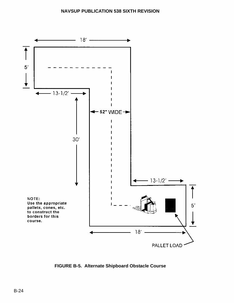
NAVSUP PUBLICATION 538 SIXTH REVISION
B-24
FIGURE B-5. Alternate Shipboard Obstacle Course
NAVSUP PUBLICATION 538 SIXTH REVISION
B-25
d. Upon completion of step c, perform a post-operational inspection, using MHE Inspection Form (figure 8-1) and the inspection procedures (page 8-5).
4. TEACHING PROCEDURES.
a. Instructor shall demonstrate each step in the Lesson Outline.
5. EQUIPMENT AND MATERIALS.
a. MHE Inspection Form (figure 8-1).
b. Type E/EE Electric Pallet Truck.
c. Pallet loads.
d. Pallets, cones, etc. (as appropriate to simulate obstacle course borders).

NAVSUP PUBLICATION 538 SIXTH REVISION
B-26
LESSON NO. 10
Proficiency Test
Day 5 - Jobsite 8.0 Hours
1. OBJECTIVE. Students shall satisfactorily pass a written test and, while observing all safety precautions and regulations, satisfactorily complete an operational skills demonstration consisting of inspecting, operating, and securing MHE.
2. LESSON OUTLINE. This proficiency test shall be conducted in two sections: written and operational skills demonstration. The instructor shall prepare a local written test or request one from the Director, Naval PHST Center (Code G1), Naval Surface Warfare Center, Indian Head Division Detachment Picatinny, Building 458, Whittemore Avenue, Picatinny Arsenal, NJ 07806-5000. This test shall minimally consist of 25 multiple choice questions based on the operational safety regulations in chapter 5. The retention of the graded written test is at the discretion of the instructor’s CO/OIC in accordance with local procedures. The operational skills demonstration shall consist of six parts given in a continuous sequence as follows:
a. Part 1 - Students shall perform a pre-operational MHE inspection using MHE Inspection Form (figure 8-1) and the inspection procedures (page 8-5). The students shall verbally address each inspection criteria to the instructor. The instructor shall deduct one point for each inspection criteria not reported or performed.
b. Part 2 - Students shall break out one pallet (nominal 48 x 40 x 36 inches weighing at least 500 pounds) from a stack of four pallets (two high by two wide) or two pallets (side-by-side) for electric pallet trucks only. The instructor shall deduct one point for each of the following applicable infractions:
(1) Failure to fasten seat belt, if equipped. See paragraph 5-3.2.g. for shipboard exceptions.
(2) Improper use of fork stop (figure 3-13), if required.
(3) Bumping a pallet.
(4) Improper penetration of forks.
(5) Forks protruding through pallet.
(6) Lifting pallet with tilt control.
(7) Failure to look back over both shoulders before traveling in reverse direction.
(8) Failure to sound horn before traveling in reverse direction.
(9) Failure to have full tilt on load before traveling in any direction.

NAVSUP PUBLICATION 538 SIXTH REVISION
B-27
(10) Dragging pallet to be lifted across the top of the remaining pallet.
(11) Failure to lower pallet approximately 4 inches above the ground/deck before traveling.
(12) Foot not on brake when lifting and tilting.
c. Part 3 - Students shall drive with a pallet (nominal 48 x 40 x 36 inches weighing at least 500 pounds) in the forward and reverse directions through a straight aisle course (40 foot long x 52 inch wide) with 12 pallets, cones, etc., equally spaced along each side. Refer to figure B-3 for straight aisle course illustration. If the student hits two or more pallets, cones, etc., then the student shall not continue the test.
d. Part 4 -
(1) Students shall drive one pallet (nominal 48 x 40 x 36 inches weighing at least 500 pounds) through a 32-1/2 foot diameter obstacle course. The circle’s perimeter is formed by placing 12 pallets, cones, etc., at an equal distance spaced 4 feet 6 inches apart from each other. Refer to figure B-3 for the obstacle course illustration. Students will be required to weave in and out between the pallets, cones, etc., in the forward and reverse directions. If the student hits two or more pallets, cones, etc., the student shall not continue this test.
(2) Alternate (Electric Pallet Trucks Only). Aboard ships with limited deck space, such as cruisers, frigates, destroyers, etc., the alternate obstacle course shall be configured in accordance with figure B-3. Students shall lift one pallet (nominal 40 x 40 x 36 inches weighing at least 500 pounds), travel with the load in the reverse direction to the final destination, and then drive in the forward direction back to the original location. The course’s borders shall be configured using the appropriate pallets, cones, etc. If the student hits two or more pallets, cones, etc., the student shall not continue the test.
e. Part 5 - Students shall restow one pallet (nominal 48 x 40 x 36 inches weighing at least 500 pounds) onto a stack of four pallets (two high by two wide) or two pallets (side-by-side) for electric pallet trucks only. The instructor shall deduct one point for each of the following applicable infractions:
(1) Failure to restow pallet from opposite side.
(2) Failure to level pallet within 6 inches of stow.
(3) Failure to land pallet squarely.
(4) Lowering pallet with tilt.
(5) Bumping pallet into position.
(6) Failure to look before backing.
(7) Dragging pallet.

NAVSUP PUBLICATION 538 SIXTH REVISION
B-28
(8) Failure to lower forks.
(9) Improper use of spacer.
f. Part 6 - Students shall return the pallet to the original starting position and secure MHE. The instructor shall deduct one point for each of the following applicable infractions:
(1) Failure park MHE in the designated area.
(2) Failure to lower forks to the ground/deck.
(3) Failure to set the parking brake.
(4) Failure to neutralize controls.
(5) Failure to disconnect battery connector cable (electric only) after dismounting MHE.
(6) Failure to remove key.
(7) Each item verbally not reported or performed by the student to the instructor during the post-operational inspection of the MHE, using MHE Inspection Form (figure 8-1) and the inspection procedures (page 8-5).
3. INSTRUCTIONAL PROCEDURES. Instructor shall read the instructions to the students, emphasizing that the students must have the ability to understand and follow written and verbal instructions.
4. INSTRUCTION AIDS.
a. Operational skill test raw score sheet.
b. MHE operator training certificate.
c. MHE operator written test.
5. EQUIPMENT AND MATERIALS.
a. Forklift truck or electric pallet truck, 4000/6000-pound capacity.
b. Four pallets (nominal 48 x 40 x 36 inches weighing at least 500 pounds).
c. MHE Inspection Form (figure 8-1).
d. Pallets, cones, etc. (as appropriate to simulate the obstacle course borders).

NAVSUP PUBLICATION 538 SIXTH REVISION
B-29
OPERATIONAL SKILL TEST RAW SCORE SHEET
PART ONE: Pre-Operational Inspection Deductions
Color, Markings Type
Restrictions
Test Date
Capacity
Battery
Static Tires or Straps
External Conditions Weldments
Loose or Missing Bolts
Lift Chains
Hoses - Leaks
Cylinders Leaks
Fork Stops
Forks
Fork Pins
Battery Connector Cable
Hydraulic Cylinders Hoist
Tilt
Sideshift
Brakes Parking Brake
Foot Brake
Seat Brake
Seat Belt
Warning Device (Horn)
TOTAL DEDUCTIONS PART ONE
PART TWO: Breakout Pallet Deductions
Seat belt not fastened
Improper use of spacer
Bumping pallet
Improper penetration of forks
Forks protruding through pallet
Lifting pallet with tilt control
CLICK HERE TO REPRODUCE AND ANNOTATE THIS SCORE SHEET

NAVSUP PUBLICATION 538 SIXTH REVISION
B-30
Failure to look before backing
Failure to sound horn before backing
Failure to have full tilt on pallet
Dragging pallet
Failure to lower pallet approximately 4 inches before traveling
Foot not on brake when lifting and fitting
TOTAL DEDUCTIONS PART TWO
PART THREE: Driving Through Straight Aisle Deductions
Forward Pylons Hit
Stops/Slows
Reverse Pylons Hit
Stops/Slows
TOTAL DEDUCTIONS PART THREE
PART FOUR: Obstacle Course Deductions
Forward Pylons or Pallet Hit
Stops/Slows
Reverse Pylons or Pallet Hit
Stops/Slows
TOTAL DEDUCTIONS PART FOUR
PART FIVE: Restow Pallet Deductions
Failure to restow pallet from opposite side
Failure to level pallet within 6 inches of stow
Failure to land pallet squarely
Lowering pallet with tilt
Bumping pallet into position
Failure to look before backing
Dragging pallet
Failure to lower forks
Improper use of spacer
TOTAL DEDUCTIONS PART FIVE
PART TWO: Breakout Pallet Deductions
CLICK HERE TO REPRODUCE AND ANNOTATE THIS SCORE SHEET

NAVSUP PUBLICATION 538 SIXTH REVISION
B-31
PART SIX: Secure MHE Deductions
Failure to park in designated area
Failure to lower forks to the ground/deck
Failure to set parking brake
Failure to neutralize controls
Failure to disconnect battery connector cable (electric drive only) after dismounting MHE
Failure to remove key
Post-Operational Inspection Deductions
Color, Markings Type
Restrictions
Test Date
Capacity
Battery
Static Tires or Straps
External Conditions Weldments
Loose or Missing Bolts
Lift Chains
Hoses - Leaks
Cylinders Leaks
Fork Stops
Forks
Fork Pins
Battery Connector Cable
Hydraulic Cylinders Hoist
Tilt
Sideshift
Brakes Parking Brake
Foot Brake
Seat Brake
Seat Belt
Warning Device (Horn)
TOTAL DEDUCTIONS PART SIX
CLICK HERE TO REPRODUCE AND ANNOTATE THIS SCORE SHEET
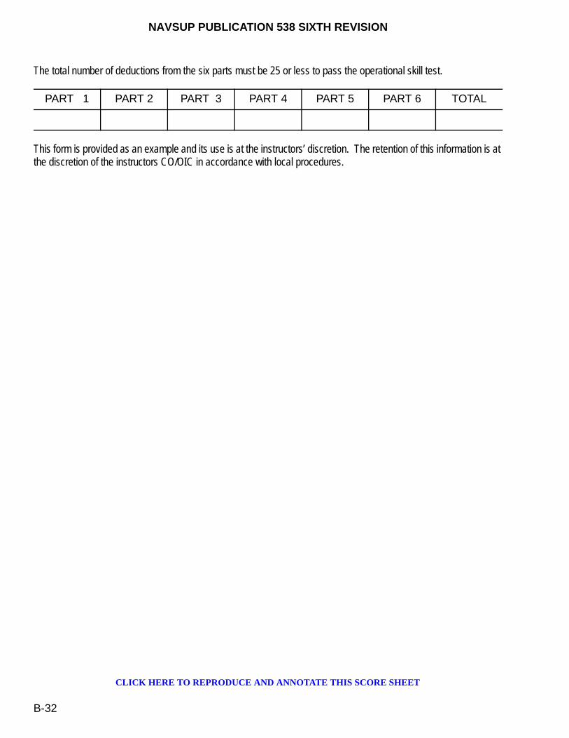
NAVSUP PUBLICATION 538 SIXTH REVISION
B-32
The total number of deductions from the six parts must be 25 or less to pass the operational skill test.
This form is provided as an example and its use is at the instructors’ discretion. The retention of this information is at the discretion of the instructors CO/OIC in accordance with local procedures.
PART 1 PART 2 PART 3 PART 4 PART 5 PART 6 TOTAL
CLICK HERE TO REPRODUCE AND ANNOTATE THIS SCORE SHEET
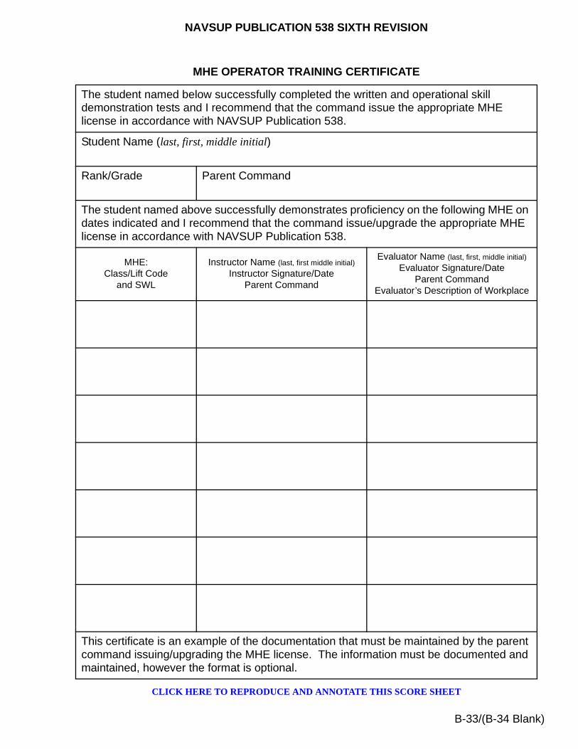
NAVSUP PUBLICATION 538 SIXTH REVISION
B-33/(B-34 Blank)
MHE OPERATOR TRAINING CERTIFICATE
The student named below successfully completed the written and operational skill demonstration tests and I recommend that the command issue the appropriate MHE license in accordance with NAVSUP Publication 538.
Student Name (last, first, middle initial)
Rank/Grade Parent Command
The student named above successfully demonstrates proficiency on the following MHE on dates indicated and I recommend that the command issue/upgrade the appropriate MHE license in accordance with NAVSUP Publication 538.
MHE:Class/Lift Code
and SWL
Instructor Name (last, first middle initial)
Instructor Signature/DateParent Command
Evaluator Name (last, first, middle initial)
Evaluator Signature/DateParent Command
Evaluator’s Description of Workplace
This certificate is an example of the documentation that must be maintained by the parent command issuing/upgrading the MHE license. The information must be documented and maintained, however the format is optional.
CLICK HERE TO REPRODUCE AND ANNOTATE THIS SCORE SHEET

This page left intentionally blank

NAVSUP PUBLICATION 538 SIXTH REVISION
C-1
APPENDIX C
MATERIALS HANDLING EQUIPMENTASSIST CHECKLIST
C-1. GENERAL
This appendix provides a checklist for shipboard and shore based use, as appropriate, to assist the ships crew or personnel ashore in evaluating their MHE operations and to provide needed assistance and information.
Ship/Shore Activity Name _____________________________
Date of Visit _________________
C-2. MHE ADMINISTRATION
a. Determine who owns/reports on the MHE.
b. Advise the ship/shore activity of their NAVSUP WSS, TYCOM, Fleet Issue Control Point (FICP) and MHE In-Service Engineering Agency (ISEA) and Hardware Systems Command (HSC) representatives.
Dept POC Phone
Dept POC Phone
Dept POC Phone
NAVSUP WSS: Code 8341 POC DSN
Comm
POC DSN
Comm
TYCOM: POC DSN
Comm
FICP: POC DSN
Comm

NAVSUP PUBLICATION 538 SIXTH REVISION
C-2
c. The following documents should be on board. (Check if available)
(1) NAVSUPINST 10490.33 (series) ________
(2) NAVICPINST 10490.4 (series) _______
(3) NAVSEA SW023-AH-WHM-010 _______
(4) Technical Manuals for each type of MHE on board _______
(5) Allowance Parts List (APL) for each type of truck on board _______(Note: Not all MHE have APL’s; check EMACS to verify)
(6) Product Quality Deficiency Report SF 368, figure 7-2 (blanks) _______
(7) MHE Inspection Form, figure 8-1 (Daily Checklist Form) (blanks) _______
(8) 3-M Data Maintenance Index Pages and Maintenance Requirement Cards for all MHE on board. _______
(9) Technical Feedback Report (TFBR) Form _______
If any of this data is unavailable, the ship should be directed to work through their TYCOM representative and local FICP coordinator. Shore activities should be directed to work through their NAVSUP FLC Regional Manager and NAVSUP WSS to obtain this data. Any item with a stock number can be ordered through normal MILSTRIP process.
C-3. MHE MANAGEMENT
C-3.1. ALLOWANCE VERIFICATION.
a. Verify that MHE aboard conforms to the reported ships inventory from the EMACS data base which can be obtained from the local NAVSUP FLC. All MHE should have a USN painted on the truck. List any discrepancies.
ISEA: PHST Center POC DSN
Comm
HSC (Afloat): NAVSEA POC DSN
Comm
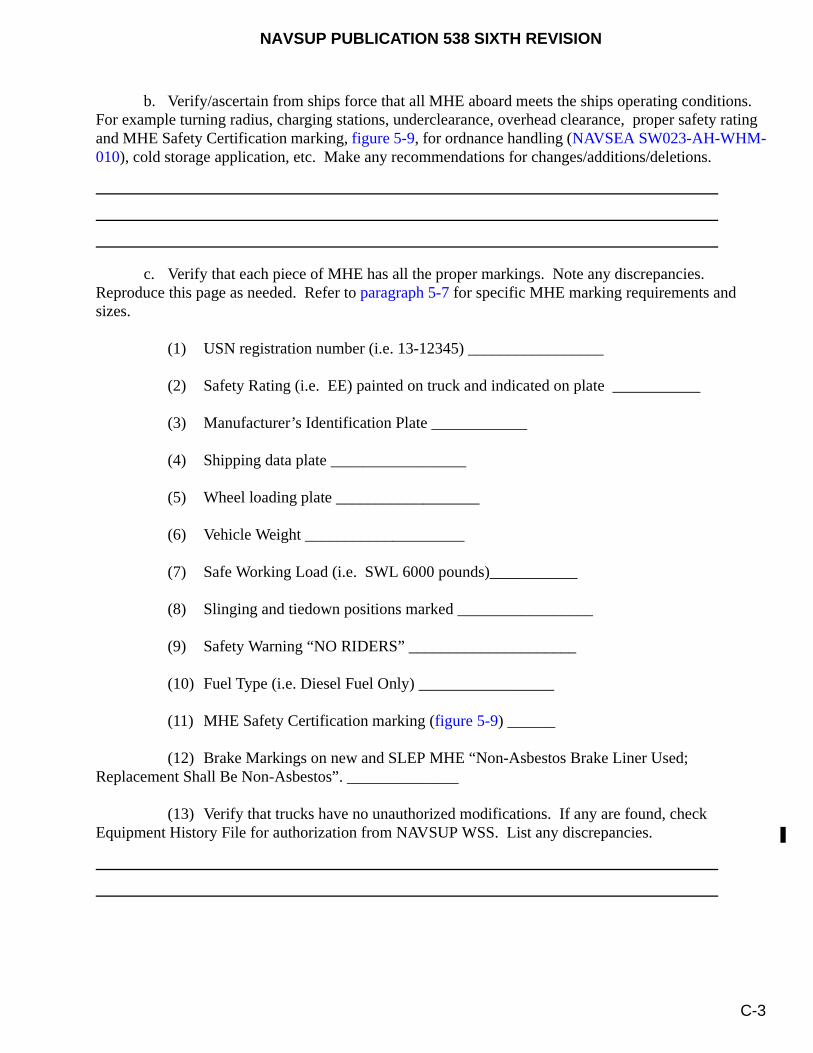
NAVSUP PUBLICATION 538 SIXTH REVISION
C-3
b. Verify/ascertain from ships force that all MHE aboard meets the ships operating conditions. For example turning radius, charging stations, underclearance, overhead clearance, proper safety rating and MHE Safety Certification marking, figure 5-9, for ordnance handling (NAVSEA SW023-AH-WHM-010), cold storage application, etc. Make any recommendations for changes/additions/deletions.
c. Verify that each piece of MHE has all the proper markings. Note any discrepancies. Reproduce this page as needed. Refer to paragraph 5-7 for specific MHE marking requirements and sizes.
(1) USN registration number (i.e. 13-12345) _________________
(2) Safety Rating (i.e. EE) painted on truck and indicated on plate ___________
(3) Manufacturer’s Identification Plate ____________
(4) Shipping data plate _________________
(5) Wheel loading plate __________________
(6) Vehicle Weight ____________________
(7) Safe Working Load (i.e. SWL 6000 pounds)___________
(8) Slinging and tiedown positions marked _________________
(9) Safety Warning “NO RIDERS” _____________________
(10) Fuel Type (i.e. Diesel Fuel Only) _________________
(11) MHE Safety Certification marking (figure 5-9) ______
(12) Brake Markings on new and SLEP MHE “Non-Asbestos Brake Liner Used; Replacement Shall Be Non-Asbestos”. ______________
(13) Verify that trucks have no unauthorized modifications. If any are found, check Equipment History File for authorization from NAVSUP WSS. List any discrepancies.

NAVSUP PUBLICATION 538 SIXTH REVISION
C-4
(14) Check trucks for proper corrosion control/paint. All exposed surfaces should be painted or adequately protected. Note any deficiencies.
(15) Verify that trucks have daily operators log and that any major deficiencies are being reported.
(16) (Shipboard Only) Shipboard Marking “SHIPBOARD USE APPROVED” ____________
(17) (Shore Activity Only) Verify that trucks have seat belts/safety harness (stock selector only). List any discrepancies/plan of action to install seat belts.
C-3.2. QUALITY DEFICIENCIES REPORTS (QDR’S).
a. What action does the ship/shore activity take if they have problems with a newpiece of MHE? (Are ships working with MHE Regional Manager/TYCOM/FICP Rep’s or are shore activities working with NAVSUP WSS/NAVSUP FLC Reps?)
b. Do they understand the QDR process __________? If not explain. All shipboard QDR’s go to the TYCOM first.
c. The ship/shore activity should maintain a file on QDR’s and if not resolved they should send out a tracer. Review tracking system and provide any recommendations.

NAVSUP PUBLICATION 538 SIXTH REVISION
C-5
C-3.3. REPLACEMENTS.
a. What procedures does the ship/shore activity use to obtain a replacement forklift and/or transfer/dispose of an existing piece of MHE? Does the ship/shore activity work through their TYCOM/MHE Regional Manager (ships only) and Regional NAVSUP FLC (shore activity only)? Are trucks returned in good condition?
b. What procedures does the ship/shore activity use to request an increase to their current MHE allowance or advise if an alternative piece of MHE is required? Is the ship working through their TYCOM/ FICP/MHE Regional Manager Representatives?
c. (Shore Activity Only) Is the shore activity aware of the MHE Service Life Extension Program (SLEP) through their Regional NAVSUP FLC and how to obtain replacement/SLEP MHE?
d. (Shore Activity Only) Does the shore activity lease any MHE and are they aware of the services offered through their Regional NAVSUP FLC representative?
C-3.4. REPORTING/TRACKING.
a. Is the ship/shore activity using EMACS to track their MHE? If not, have them contact TYCOM or Regional NAVSUP FLC representative to get access and training. Verify they have completed their last annual report and that they are submitting quarterly reports.
b. Does each piece of MHE have a equipment history file containing all pertinent information? If not, provide assistance in establishing some type of record keeping system.
NAVSUP PUBLICATION 538 SIXTH REVISION
C-6
C-4. MHE REPAIR AND MAINTENANCE
C-4.1. PREVENTIVE MAINTENANCE (PM).
a. Verify that PM is being performed and what procedure or guidance is used to schedule preventive maintenance? Are they using the Technical Manual and the MIP to schedule the work?
b. Who does the PM work and are they qualified? Do they follow the Technical Manual and/or the MRC’s for performing PM? Any deficiencies with the MIP/MRC’s should be reported to the MHE ISEA by a TFBR with a copy to the TYCOM (shipboard only). Any technical manual deficiencies should be reported to NAVSUP WSS with a copy to the TYCOM (shipboard only).
c. How are PM actions recorded and are they included in the EMACS report and Equipment History File?
d. Who verifies that PM has been accomplished and checks on quality of service?
e. (Shore Activity Only) Is the shore activity aware of the Regional NAVSUP FLC program for maintaining their MHE? This program is not available in all regions. Verify with Regional NAVSUP FLC to see what is currently available.

NAVSUP PUBLICATION 538 SIXTH REVISION
C-7
C-4.2. REPAIRS.
a. Verify how unscheduled maintenance is performed. Are personnel qualified to perform the
repairs? What level repairs are performed?
b. Do they ever use other repair sources (i.e., PWC, SIMA, contractors) and which ones? Are they aware of the MHE Regional Manager’s ability to coordinate all maintenance actions for them?
c. Verify that procedures are in place to check all repairs to ensure the integrity of the Safety Ratings. Ensure all covers, gaskets, shields etc. are reinstalled on the trucks after repairs. Also only qualified repair parts should be used. Note any deficiencies. Advise on corrective action plans to take.
d. Verify that all maintenance actions are properly recorded in the Equipment History File and in EMACS. If EMACS is not used, how are actions being recorded? Note any deficiencies.
e. Do they have proper tools and area to perform required maintenance operations? Make any recommendations.
f. Is there a quality control program in place to verify all repairs? Who inspects repairs after completion?

NAVSUP PUBLICATION 538 SIXTH REVISION
C-8
C-4.3. PARTS SUPPORT.
a. Do they have adequate parts/COSAL support to perform PM operations? If no, list deficiencies and check to see a request to change the APL has been made.
b. What procedures are in place to order repair parts? For ships, what about when in port or deployed? Do they know they can go to Regional NAVSUP FLC/TYCOM/MHE Regional Manager for assistance or call 1-800 numbers in some instances?
c. How do they order replacement batteries for electric forklifts? Are they shipboard qualified?
C-4.4. MAINTENANCE TRAINING.
a. Do they feel they are adequately trained to perform PM, repairs and maintenance? If not, what type of training do they feel they need?
b. Are the technical manuals and MRC’s adequate guides in performing PM and other maintenance and repairs? Any recommendations?
c. Are any procedures in place when maintenance personnel rotate out to brief replacements?
NAVSUP PUBLICATION 538 SIXTH REVISION
C-9
C-5. MHE OPERATIONS
C-5.1. OPERATOR TRAINING AND LICENSING.
a. What type of training do the MHE operators receive? Are the operators trained in the proper use of MHE for ordnance handling, and hazardous material? If not, training needs to be obtained.
b. Are licenses issued to each operator and by whom?
c. What controls are in place to prevent unauthorized use of MHE? Are they effective? Make any recommendations.
C-5.2. STORAGE/STOWAGE.
a. How is MHE stored/stowed? Are electric trucks protected from the elements and used for interior operations? Are all other trucks protected from the elements when not in use for long periods of time?
b. (Shipboard Only) Are tiedowns used when MHE is not being used for long periods of
time?
NAVSUP PUBLICATION 538 SIXTH REVISION
C-10
C-5.3. BATTERY CHARGING.
a. Verify that adequate chargers/charging stations are available for all electric MHE. Note any discrepancies.
b. Are electric batteries of sufficient amp capacity for required operations?
C-5.4. MHE INSPECTION FORM (DAILY INSPECTIONS).
a. Who reviews the MHE Inspection Form? Are these forms maintained for each piece of MHE? List any discrepancies.
b. Who reviews the MHE Inspection Form and are maintenance actions being corrected in a timely manner?
C-5.5. ACCIDENTS.
a. How are accidents reported and what corrective measures are taken?
Any comments/recommendations to help improve MHE operations:
NAVSUP PUBLICATION 538 SIXTH REVISION
C-11/(C-12 Blank)
After completing form, provide a copy to the ship/shore activity (and to ship’s TYCOM).Send original to:
CommanderNAVSUP Weapon Systems Support (NAVSUP WSS)
Code 8341 (T. Lewis)5450 Carlisle Pike
P.O. Box 2020Mechanicsburg, PA 17055-0788
Assist Team Member
Mailing Address
Phone Comm.
DSN
Email Address

This page left intentionally blank

NAVSUP PUBLICATION 538 SIXTH REVISION
D-1
APPENDIX D
SHIPMENT AND TRANSPORTATION OF MHE
D-1. GENERAL
This appendix provides shipment and transportation guidelines for Materials Handling Equipment (MHE) intended to be transported on enclosed vans and trailers, or on flatbed trailers from short term storage and long term storage. Additionally, general truckload requirements are provided to properly and safely block and brace MHE for transportation. These procedures are presented to ensure MHE will not be degraded or damaged during shipment. If provided, refer to manufacturer recommendations supporting any shipment and transportation requirements associated with MHE. The truckload requirements presented in this chapter apply to all classes of MHE provided they can physically be capable of being transported by the offering motor vehicle.
D-2. SHORT TERM STORAGE REQUIREMENTS
MHE intended to be shipped from short-term storage, described in chapter 10, requires an inspection, operational test, and maintenance procedures prior to shipment.
D-2.1. INSPECTION, TEST AND MAINTENANCE. The following requirements will be performed on each unit:
a. Conduct an initial receipt inspection on each unit in accordance with paragraph 8-4.
b. Operate the unit for a minimum of 30 minutes.
c. Perform the periodic inspection, exercising and maintenance with the requirements specified in paragraph 10-8 and with the Maintenance Requirement Card (MRC), as required, based on the total storage time interval.
d. Accompany the appropriate technical manual and equipment history file with each piece of MHE.
D-2.2. SHIPMENT REQUIREMENTS. The following procedures document the general shipment requirements prior to loading MHE onto a motor vehicle:
a. Whenever practical, enclosed-type motor vehicles shall be used to transport MHE. Flatbed trailers containing waterproof tarpaulins may be used for the transportation of MHE. When tarpaulins are used, they shall be properly secured to prevent abrasion damage to the painted MHE surfaces.
b. Forks shall be secured in carriage detents with the latches closed.

NAVSUP PUBLICATION 538 SIXTH REVISION
D-2
c. Folding-type forks shall be secured for shipment in accordance with figures D-1, D-2, and D-3.
d. Forks that are non-folding or that are detachable shall be secured to the carriage using steel strapping or web straps. Free ends of the web straps shall be properly secured to prevent abrasion damage to the painted MHE surfaces.
FIGURE D-1. Typical Application of Metal Strapping Securing Forks to Truck
FIGURE D-2. Typical Application of Metal Clamps Securing Forks to Truck

NAVSUP PUBLICATION 538 SIXTH REVISION
D-3
FIGURE D-3. Clamping Device Used for Securing Forks on MHE
D-2.3. TRANSPORTATION REQUIREMENTS. Upon completion of the requirements specified in paragraphs D-2.1 and D-2.2, MHE shall be properly blocked and braced onto a motor vehicle with the truckload requirements described in paragraph D-4.
D-3. LONG TERM STORAGE
MHE intended to be shipped from long-term storage, described in chapter 12, requires an inspection, operational test, and maintenance procedures prior to shipment.
D-3.1. INSPECTION, TEST AND MAINTENANCE. The following requirements will be performed on each unit:
a. De-preserve engines, transmissions, fuel systems, hydraulic systems, brake systems, etc. If applicable, clean battery contactors on electric MHE. Clean armatures, as required.
b. Drain and refill all fluids with manufacturer recommended fluids.
c. Conduct an initial receipt inspection on each unit in accordance with paragraph 8-4.
d. Operate the unit for a minimum of 30 minutes.
e. Perform the periodic inspection, exercising and maintenance requirements specified in paragraph 11-8 and with the Maintenance Requirement Card (MRC), as required, based on the total storage time interval.

NAVSUP PUBLICATION 538 SIXTH REVISION
D-4
f. Accompany the appropriate technical manual, parts, test equipment as supplied, and the equipment history file with each piece of MHE.
D-3.2. SHIPMENT REQUIREMENTS. The shipment requirements specific in paragraph D-2.2 for short term storage also apply for long term storage.
D-3.3. TRANSPORTATION REQUIREMENTS. Upon completion of the requirements specified in paragraphs D-3.1 and D-3.2, MHE shall be properly blocked and braced onto a motor vehicle with the truckload requirements described in paragraph D-4.
D-4. TRUCKLOAD REQUIREMENTS
All MHE being offered for transportation on a motor vehicle shall be properly blocked and braced in accordance with NAVSEASYSCOM Drawing 6214257. This drawing illustrates full and less than full truckload requirements for reaching and tiering, and for sit-down type forklift trucks. However, these requirements apply to all other MHE classes that are physically capable of being transported on enclosed vans and trailers or on flatbed trailers.

NAVSUP PUBLICATION 538 SIXTH REVISION
E-1
APPENDIX E
EMERGENCY RECLAMATION PROCEDURES
E-1. GENERAL
This appendix documents the emergency reclamation procedures and materials required (refer to table E-1) to prevent damage and corrosion to MHE/SMSE that have been exposed to salt water, water immersion, or fire extinguishing agents. It is essential to immediately begin reclamation procedures of cleaning, drying, preservation, repair and operational functions.
a. The primary method for removing salt water and fire extinguishing agents shall be used with a sufficient quantity of fresh water.
(1) Flush all internal and external areas with clean, fresh water. An exception to this will be the type EE forklifts trucks due to the extensive electrical components contained within the unit. Follow the guidelines that are found in paragraph 6 for the EE forklift trucks. Whenever possible, units or components that have been removed should be immersed and flushed thoroughly in clean, fresh water. A 32-gallon garbage container may be used for this purpose. Tilt the equipment back and forth to aid in draining off excess water.
CAUTION:
Compressed air used for drying can create airborne particles that may enter the eyes. Pressure shall not exceed 10 psi. Eye protection is required.
(2) Blow off excess water with not more than 10 psi air pressure. Deflect jet of air off interior, back, and sides of enclosures to diffuse.
(3) If any evidence of salt or fire extinguishing agents remains, a second cleaning action should be initiated.
b. The Emergency Reclamation Team will establish an initial screening of the support equipment.
(1) Remove all covers, access panels, modules, and normally removed components.
(2) Examine the individual components thoroughly for evidence of salt water, fire extinguishing agents, smoke, oil films, heat, and fire damage.
(3) Examine the individual components for evidence of corrosion.
(4) Examine encapsulated and conformal coated circuit boards for damage caused by salt water, fire extinguishing agents, and cleaning solvents. Pay particular attention to conformal coatings and circuit board laminates that are discolored, softened, or deformed.

NAVSUP PUBLICATION 538 SIXTH REVISION
E-2
(5) Disassemble and inspect electrical connectors and receptacles for damage and signs of corrosion. Pay particular attention to seals and gaskets.
(6) Examine electric motors, generators, and receivers for damage. Pay particular attention to lubricated fittings and sealed bearings.
(7) Examine control boxes for damage and signs of deterioration from cleaning solvents. Pay particular attention to faceplates, seals, and rubber boots around toggle switches and knobs.
(8) Examine shock mounts, mounting racks, cases, chassis, and cover plates for buckling, disfiguration, and fire damage. Check painted surfaces for cracks or nicks. Pay particular attention to rubber shock mounts.
(9) Disassemble and inspect all components for smoke and heat damage.
c. Components that show no signs of damage or corrosion shall be functionally inspected. This shall be done as specified by the applicable service manuals. Equipment shall be placed back into service in accordance with established procedures.
d. Those components that show damage shall be repaired as specified by the applicable service manuals.
e. Additional guidelines can be found in NAVAIR 16-1-540; TO 1-1-689; TM 1-1500-343-23; and COMNAVAIRFORINST 4790.2 (series).

NAVSUP PUBLICATION 538 SIXTH REVISION
E-3/(E-4 Blank)
Table E-1. Reclamation Materials List
1 32 Gallon Garbage Container 7240-00-160-0440 5EA
2 Plastic Pail 7240-00-246-4097 4EA
3 Garden Hose-50FT 4720-00-729-5338 4EA
4 Acid Brushes 7920-00-514-5338 2BX
5 Varnish Brushes H-B-695-1 6EA
6 Vacuum Cleaner, Pneumatic 9710-00-807-3704 1EA
7 Pressure Regulator, Air 4240-00-029-7148 1EA
8 Adapter, Hanger Deck Air Local Manufacture 1EA
9 Adapter, Shop Air Local Manufacture 1EA
10 Air Blower 4940-01-168-7068 1EA
11 Pump, Back Pack 4320-00-289-8912 2EA
12 Rubber Aprons 8415-00-634-5023 10EA
13 Rubber Gloves 8415-00-266-8677 10PR
14 Goggles, Chemical 4240-11-190-6432 10PR
15 China Markers (White) 7510-00-240-1525 1EA
16 Water/Crash/Fire Damaged Part Tag NARF 3750/1 100EA
17 Record Book (8.5 X 11) 7530-00-222-3525 1EA
18 Paper Towels (Chem-Wipes) 7920-00-543-6492 2BX
19 Chest. Collapsible Storage 8460-00-212-8080 2EA
20 Abrasive Mat, MIL-A-9962 5350-00-967-5089 1EA
21 Scouring Pads 7920-00-151-6120 1PG
22 Sponge 7920-00-222-2559 20EA
23 Tooth Brush 5830-00-542-2048 3BX
24 Face Shield, Industrial 4240-00-542-2048 5EA
25 Bottle, Plastic, Manual Spray 6640-00-488-7952 5EA
26 Bottle Washing 6640-00-299-8493 5EA
27 Pipe Cleaners 9920-00-292-9946 1PG
28 Spray Gun Oil and Solvent 4940-00-248-0866 2EA
29 Nozzle, Water Adjustable 4730-00-223-6731 2EA
HAZMAT
30 Aircraft Cleaning Compound MIL-C-43016TY1 2CN
31 Water Displacing Compound MIL-C-81309TY3 2CN
32 Solvent, Dry Cleaning PD-680 TYII 2GL
33 Oil, General Purpose Lubricant VVL-800 2CN
34 Corrosion Prevention Compound MIL-C-16173 Grade 4 2CN
35 Isopropyl Alcohol, TT-I-735A 6810-00-286-5435 1QT

This page left intentionally blank
NAVSUP PUBLICATION 538 SIXTH REVISION
F-1
APPENDIX F
DECK SCRUBBER OPERATOR’S TRAINING COURSE
F-1. PURPOSE
This appendix establishes the policy, responsibilities and requirements for training and licensing of personnel to operate a Deck Scrubber. This instruction directs Maintenance Officers (MO’s) to establish a formal course of instruction on the Deck Scrubber. For this reason, the program manager for Shipboard Mobile Support Equipment (SMSE) at NAVSUP Weapon Systems Support (NAVSUP WSS), Code 8341, has established this course meeting the minimum requirements that U.S. Navy shipboard personnel must successfully complete prior to being issued a license to operate the Deck Scrubber (Model No. SRS1550-DN-A).
F-2. COURSE VARIATIONS
The Commanding Officer/Officer-In-Charge (CO/OIC), at their discretion and under their documented approval, may authorize variations as needed to adopt this course to train, certify and license Deck Scrubber operators.
F-3. SAFETY AND HAZARD AWARENESS
Any time an operator or instructor has apprehension concerning personal safety, they should signal for a “Training Time-Out (TTO)” to clarify the situation or procedure, and receive or provide additional instruction as appropriate. TTO signals, other than verbal, shall be appropriate to this training environment. Instructors are responsible for maintaining situational awareness and shall be constantly alert to signs of student behavior that may impair safe completion of the training exercise, and shall immediately stop the training, identify the problem or situation, and make a determination to continue or discontinue training. The safety precautions contained in this course are applicable to the instructor and the operators (students). They are basic and general in nature. Personnel who operate or maintain equipment in support of this course must be thoroughly familiar with all aspects of personnel safety and strictly adhere to the every general and specific safety precautions contained in the operating and emergency procedures along with all governing directives. All personnel must have a comprehensive knowledge of emergency procedures, which prescribe courses of action to be followed in the event of equipment failure or human error as stated in the local shipboard mishap reporting. Strict adherence to approved and verified operating, emergency and maintenance procedures is mandatory. As a minimum, each individual is responsible for knowing, understanding and observing all safety precautions applicable to the command, course, their work and their work area. In addition, all personnel are responsible for observing the following safety precautions:
a. Reporting for work rested and emotionally prepared for the work tasks at hand.

NAVSUP PUBLICATION 538 SIXTH REVISION
F-2
b. Using good judgment in all their functions, commensurate with the work at hand.
c. Reporting any unsafe conditions, or any equipment or material uncertainties, which may be considered to be unsafe, and any unusual or developing hazards.
d. Warning others believed to be in danger of known hazards or by failure to observe safety precautions.
e. Reporting any accident, injury or evidence of impaired health occurring in the course of their work or during any non-training environment.
f. Wearing or using the protective clothing and/or equipment of the type required, approved and supplied for the safe performance of their work.
g. Wearing appropriate hearing protective devices when in the vicinity of a designated noise hazard area or noise hazard operation.
h. Hazard materials (HAZMAT) are used during this course. Students must be made aware of the nature of the HAZMAT being used, symptoms of exposure, safety precautions to be observed when handling these materials, and the proper disposal requirements. This is accomplished by ensuring each student has read the appropriate Material Safety Data Sheet (MSDS) for each HAZMAT used and signing a statement of understanding. The following HAZMAT is discussed in the lesson plans and used during the training of operators:
(1) Jet Fuel JP5 (MIL-DTL-5624)
(2) Jet Fuel JP8 (MIL-DTL-83133)
(3) Lubricating Oil, 15W-40 (MIL-PRF-2104)
(4) Hydraulic Fluid (MIL-PRF-17672)
(5) Antifreeze (A-A-52624)
(6) Dry Cleaning Solvent (PD-680, Type III)
(7) Solvent-Detergent Cleaning Compound (NSN: 6850-01-376-1201; 5-gallon container)

NAVSUP PUBLICATION 538 SIXTH REVISION
F-3
LESSON NO. 1
INTRODUCTION
1. INSTRUCTOR PREPARATION.
Prior to instructing students, the instructor shall:
a. Review the assigned training materials
b. Discuss the following reference documentation:
(1) NAVSUP PUB 538 – Management of Materials Handling Equipment (MHE).
(2) Naval Air Training and Operating Procedures Standardization (NATOPS) NAVAIR 00-80T-96 - Support Equipment Basic Handling and Safety Manual.
(3) NAVAIR Aviation Support Equipment Rework Facility (NAVAIRSEFAC) 0532-LP-104-9048 – Flight Deck Scrubber: Diesel Powered (Model SRS 1550-DN-A) Operational and Maintenance Manual with Parts List.
(4) Obtain an MHE Operator’s License, figure 4-2, as described in paragraph 12-3.1.
(5) Produce copies of Deck Scrubber Maintenance Index Page (MIP) 5882/013 and the associated Maintenance Requirement Cards (MRC’s).
(6) Acquire the appropriate Material Safety Data Sheets (MSDS) for the applicable HAZMAT associated with the Deck Scrubber.
2. PURPOSE OF THE DECK SCRUBBER.
The instructor will explain the purpose of the Deck Scrubber. In summary, the scrubber is intended to achieve and maintain a high degree of flight deck and hangar deck cleanliness. It is designed to remove the residual solution leaving the deck surface free from grease, oil, diesel fuel and debris. The unit contributes to a reduction of aircraft engine Foreign Object Damage (FOD) incidences and provides better traction, therefore improving personnel safety during flight operations.
NAVSUP PUBLICATION 538 SIXTH REVISION
F-4
LESSON NO. 2
DESCRIPTION AND OPERATION
1. FAMILIARIZATION OF THE DECK SCRUBBER.
The instructor will introduce to the students the Deck Scrubber (Model No. SRS1550-DN-A) as outlined in chapter 12 of this manual. This introduction shall include providing a description and illustration (paragraph 12-2.1), the operator license qualification requirements (paragraph 12-3.1.1), all operational safety requirements (paragraph 12-4), color (paragraph 12-5) and marking requirements (paragraph 12-6), initial product reporting deficiencies (paragraph 12-7), and all preventive maintenance practices (paragraph 12-8) relating to operator responsibilities, maintaining an equipment history file, preventive maintenance scheduling, maintaining the integrity of the unit and servicing requirements.
2. OPERATION DESCRIPTION OF THE DECK SCRUBBER.
The instructor will explain that the functional operation of the Deck Scrubber is to spray a cleaning solution onto the flight and hangar decks, then scrub the surface, and recover the residual solution and debris into a recovery tank for subsequent discharge in accordance with local procedures. As the scrubber moves forward, a solution dispenser sprays solution ahead of the scrubbing brushes. The brushes scrub in opposite directions creating a water-lift into the debris hopper. The vacuum system draws water from the hopper and from the area forward of the rear squeegee, and then charges it into the recovery tank. Rear squeegees leave the deck free from any residual solution.
3. FUNCTIONAL CHARACTERISTICS.
The instructor will discuss the following functional characteristics of the Deck Scrubber.
a. Engine Type – Detroit Diesel: 3 cylinder, 4 stroke; 61 horsepower at 2350 RPM; Engine Oil (15W/40; MIL-PRF-2104).
b. Fuel System – JP5 Jet Fuel (MIL-DTL-5624) or JP8 Jet Fuel (MIL-DTL-83133); 15.3-Gallon Capacity.
c. Cooling System – Antifreeze (A-A-52624) [50% Water and 50% Ethylene Glycol]; 13.4-Quart Capacity.
d. Hydraulic System – Type MIL-PRF-17672; 18.3-Gallon Capacity.
e. Electrical System – One 12-Volt Direct Current (VDC) nominal battery; 42-amp alternator.
f. Braking System –
(1) Service Brakes - Hydraulic dual caliper disc brakes; 4 total (2 on each front wheel).
(2) Parking Brakes – Mechanical caliper disc brakes; 4 total (1 on each wheel).
NAVSUP PUBLICATION 538 SIXTH REVISION
F-5
g. Tires – 8 x 16.5-inch; 6-ply foam filled (each tire).
h. General Machine Dimensions/Capacities:
(1) Length – 102 inches
(2) Width – 62 inches
(3) Height – 70.8 inches
(4) Track – 46.7 inches (front); 45.3 inches (rear)
(5) Wheel Base – 90 inches
(6) Fresh Water Tank – 510 gallons
(7) Scrub Brush Path (each) – 50 inches (width), 11 inches (diameter)
(8) Rear Squeegee Path – 56.5 inches
(9) Debris Hopper Capacity – 2.6 cubic feet
4. OPERATING CONTROLS AND INDICATORS.
The instructor will discuss and demonstrate on the Deck Scrubber the operating controls and indicators.
a. Brake Pedal – operates the hydraulic disc brakes on the two front wheels. Always use the brake speed for normal stopping and controlling machine speed on down grades.
b. Directional Control Pedal – controls the hydraulic propelling drive. Used to select the direction of swivel and propelling speed of the machine.
CAUTION
Always engage the parking brake levers before leaving the machine unattended.
c. Parking Brake Levers – controls the brake cables that are connected to the mechanical disc brakes on the wheels. Forward lever controls the front wheels and the aft lever controls the rear wheels.
d. Tank Drain Lamp – indicates when the recovery tank is nearly full.
e. Fuses – are a one-time circuit protection device designed to stop the flow of current in the event of circuit overload. There are 7 fuses:
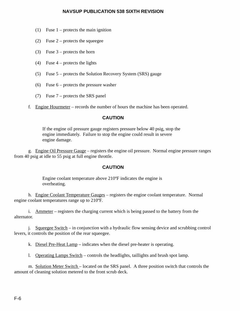
NAVSUP PUBLICATION 538 SIXTH REVISION
F-6
(1) Fuse 1 – protects the main ignition
(2) Fuse 2 – protects the squeegee
(3) Fuse 3 – protects the horn
(4) Fuse 4 – protects the lights
(5) Fuse 5 – protects the Solution Recovery System (SRS) gauge
(6) Fuse 6 – protects the pressure washer
(7) Fuse 7 – protects the SRS panel
f. Engine Hourmeter – records the number of hours the machine has been operated.
CAUTION
If the engine oil pressure gauge registers pressure below 40 psig, stop the engine immediately. Failure to stop the engine could result in severe engine damage.
g. Engine Oil Pressure Gauge – registers the engine oil pressure. Normal engine pressure ranges from 40 psig at idle to 55 psig at full engine throttle.
CAUTION
Engine coolant temperature above 210ºF indicates the engine is overheating.
h. Engine Coolant Temperature Gauges – registers the engine coolant temperature. Normal engine coolant temperatures range up to 210ºF.
i. Ammeter – registers the charging current which is being passed to the battery from the alternator.
j. Squeegee Switch – in conjunction with a hydraulic flow sensing device and scrubbing control levers, it controls the position of the rear squeegee.
k. Diesel Pre-Heat Lamp – indicates when the diesel pre-heater is operating.
l. Operating Lamps Switch – controls the headlights, taillights and brush spot lamp.
m. Solution Meter Switch – located on the SRS panel. A three position switch that controls the amount of cleaning solution metered to the front scrub deck.

NAVSUP PUBLICATION 538 SIXTH REVISION
F-7
n. Ignition Switch – controls the machine engine and accessories.
CAUTION
Do not engage the starter motor for more than 10 seconds at a time or after the engine has started, as the starter may be damaged.
o. Start Switch – engages the engine starter motor.
p. Fuel Level Gauge – indicates how much fuel remains in the fuel tank.
q. Panel Lamp – illuminates the panel gauge whenever the operating lamps are on.
r. Scrub Brush Control Lever – operates the hydraulic control valve which controls the scrub brush motors.
s. Scrub Head Position Control Lever – operates the hydraulic control valve which controls the scrub head lift cylinder.
t. Throttle Control Knob – operates a cable which controls the engine speed.
u. Solution Control Lever – operates a cable which controls the solution control valve.
v. Emergency Fuel Shutoff Switch – stops the machine engine. To reset the emergency fuel shutoff switch, flip the ignition switch down to the OFF position.
w. Steering Wheel – operates a hydraulic steering control valve mounted at the end of the steering column.
CAUTION
Never use your foot to lock or unlock the scrub head lock lever. To lock or unlock the scrub head, the scrub head must be in the raised position.
x. Scrub Head Lock Lever – controls the scrub head lock mechanism.
y. Pivot Lock Pin – used to lock the pivot joint located between the front and rear machine sections to prevent the machine from pivoting and creating a pinch area.
z. High Pressure Washer (Front) – used for routine deck maintenance in areas where the unit cannot reach and for cleaning away debris from the unit.
aa. Accessories/Attachments (Rear) – a vacuum hose and wand consisting of two 25-foot hoses, two vacuum wands and one squeegee wand allowing one or two users to collect spills not accessible with the Deck Scrubber.
NAVSUP PUBLICATION 538 SIXTH REVISION
F-8
LESSON NO. 3
OPERATIONAL SAFETY REQUIREMENTS AND PREOPERATIONAL INSPECTIONS
1. INSTRUCTOR PREPARATION.
Prior to starting this lesson, the instructor will stress the importance to the students on understanding all safety precautions and performing the preoperational inspections, the required supporting documentation and the knowledge of all safety precautions. Licensed operators must conduct mandatory prior to use inspections and functional tests to ensure the equipment is fully operational and safe to use to prevent injury to personnel or damage to the equipment. The inspection procedures contain the minimum inspection requirements. No steps may be deleted. Additional steps may be added to meet local requirements.
2. OPERATIONAL SAFETY REQUIREMENTS.
The instructor will review with the students, in its entirety, all the operational safety requirements described in paragraph 12-4. Likewise, the instructor will review with the students the appropriate MSDS sheets associated with the Deck Scrubber.
3. PRIOR TO USE INSPECTION PROCEDURES.
The instructor will distribute copies of the MIP 5882/013 and the associated MRC’s to the students. Each student will be required to conduct the mandatory inspections and functional tests on the Deck Scrubber. The instructor will discuss with the students the local procedural requirements for the safety deficiency tag-out process described in paragraph 12-8.1.1 when unsatisfactory visual inspections or functional tests are noted, and the maintenance provider responsibilities described in paragraph 12-8.1.2 when the Deck Scrubber is to be scheduled for preventive maintenance servicing. Lastly, the instructor will review the mandatory and optional documentation requirements for maintaining the equipment history file detailed in paragraph 12-8.2.

NAVSUP PUBLICATION 538 SIXTH REVISION
F-9
LESSON NO. 4
BASIC OPERATIONAL TRAINING
1. INSTRUCTOR PREPARATION.
The instructor will take the students to the Deck Scrubber (prescribed training area) and will first conduct the prior to use inspection procedures and functional tests in accordance with MIP 5882/013. Next, the instructor will identify the unit’s basic operational principles to the students. Lastly, the instructor will operate the Deck Scrubber and show the students all operations and functions while scrubbing the prescribed deck area.
2. OPERATOR USE TRAINING.
The instructor will then have each student perform the prior to use inspection requirements and then operate the Deck Scrubber in the prescribed training area. During this entire evolution, the instructor shall note the proficiency of each student.
3. DECK SCRUBBER OPERATOR TRAINING CERTIFICATE.
Following the completion of the operator use training on the Deck Scrubber, the instructor will complete the Deck Scrubber Operator Training Certificate, figure F-1, for those students who have satisfactorily completed this course. The instructor will present these completed training certificates to the ship’s Certifying Official, who will annotate “FDS” (designated as the MHE Class for the Flight Deck Scrubber as shown in table 4-1 of this publication) on each operator’s MHE Operator’s License, figure 4-2, and will issue the new license to each operator. The completed Deck Scrubber Operator Training Certificate, figure F-1, will be retained in each operator’s personal training folder.
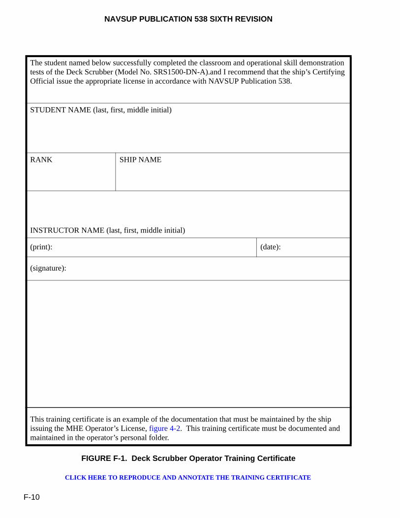
NAVSUP PUBLICATION 538 SIXTH REVISION
F-10
FIGURE F-1. Deck Scrubber Operator Training Certificate
The student named below successfully completed the classroom and operational skill demonstration tests of the Deck Scrubber (Model No. SRS1500-DN-A).and I recommend that the ship’s Certifying Official issue the appropriate license in accordance with NAVSUP Publication 538.
STUDENT NAME (last, first, middle initial)
RANK SHIP NAME
INSTRUCTOR NAME (last, first, middle initial)
(print): (date):
(signature):
This training certificate is an example of the documentation that must be maintained by the ship issuing the MHE Operator’s License, figure 4-2. This training certificate must be documented and maintained in the operator’s personal folder.
CLICK HERE TO REPRODUCE AND ANNOTATE THE TRAINING CERTIFICATE

NAVSUP PUBLICATION 538 SIXTH REVISION
G-1
APPENDIX G
QRE-3001A POWER/PRESSURE WASHER OPERATOR’S TRAINING COURSE
G-1. PURPOSE
This appendix establishes the policy, responsibilities and requirements for training and licensing personnel to operate a QRE-3001A Power/Pressure Washer, figure 12-2. As directed in paragraph 12-3.2.1a of this publication, Maintenance Officers (MO’s) are required to establish a formal course of instruction on the Power/Pressure Washer. For this reason, the Program Manager for Shipboard Mobile Support Equipment (SMSE) at NAVSUP Weapons System Support (NAVSUP WSS), Code 8341, has established this training course meeting the minimum requirements that U.S. Navy shipboard personnel must successfully complete prior to being issued a license to operate the Power/Pressure Washer (Model QRE-30001A).
G-2. COURSE VARIATIONS
The Commanding Officer/Officer-In-Charge (CO/OIC), at their discretion and under their documented approval, may authorize variations as needed to adopt this course to train, certify and license Power/Pressure Washer operators.
G-3. SAFETY AND HAZARD AWARENESS
Any time an operator or instructor has apprehension concerning personal safety, they should signal for a “Training Time-Out (TTO)” to clarify the situation or procedure, and receive or provide additional instruction as appropriate. TTO signals, other than verbal, shall be appropriate to this training environment. Instructors are responsible for maintaining situational awareness and shall be constantly alert to signs of student behavior that may impair safe completion of the training exercise, and shall immediately stop the training, identify the problem or situation, and make a determination to continue or discontinue training. The safety precautions contained in this course are applicable to the instructor and the operators (students). They are basic and general in nature. Personnel who operate or maintain equipment in support of this course must be thoroughly familiar with all aspects of personnel safety and must strictly adhere to every general and specific safety precaution contained in the operating and emergency procedures along with all governing directives. All personnel must have a comprehensive knowledge of emergency procedures, which prescribe courses of action to be followed in the event of equipment failure or human error as stated in the local shipboard mishap reporting regulations. Strict adherence to approved and verified operating, emergency and maintenance procedures is mandatory. As a minimum, each individual is responsible for knowing, understanding and observing all safety precautions applicable to this training course, their work and their work area. In addition, all personnel are responsible for observing the following safety precautions:
NAVSUP PUBLICATION 538 SIXTH REVISION
G-2
a. Reporting for work rested and emotionally prepared for the work tasks at hand.
b. Using good judgment in all their functions, commensurate with the work at hand.
c. Reporting any unsafe conditions, or any equipment or material uncertainties, which may be considered to be unsafe, and any unusual or developing hazards.
d. Warning others believed to be in danger of known hazards or of their failure to observe safety precautions.
e. Reporting any accident, injury or evidence of impaired health occurring in the course of their work or during any non-training environment.
f. Wearing or using the protective clothing and/or equipment of the type required, approved and supplied for the safe performance of their work.
g. Wearing appropriate hearing protective devices when in the vicinity of a designated noise hazard area or noise hazard operation.
h. Hazard materials (HAZMAT) are used during this course. Students must be made aware of the nature of the HAZMAT being used, symptoms of exposure, safety precautions to be observed when handling these materials, and the proper disposal requirements. This is accomplished by ensuring each student has read the appropriate Material Safety Data Sheet (MSDS) for each HAZMAT used in this training course. The following HAZMAT is discussed in the lesson plans and used during the training of operators:
(1) Jet Fuel JP5 (MIL-DTL-5624)
(2) Jet Fuel JP8 (MIL-DTL-83133)
(3) Lubricating Oil (MIL-PRF-9000)
(4) Hydraulic Fluid (MIL-PRF-17672)
(5) Antifreeze (A-A-52624)
(6) Fresh Water Detergent (MIL-PRF-32177, Type I: RITE-KEM CCSD)
NAVSUP PUBLICATION 538 SIXTH REVISION
G-3
LESSON NO. 1
INTRODUCTION
1. INSTRUCTOR PREPARATION.
Prior to instructing students, the instructor shall:
a. Review the assigned training materials.
b. Possess the following reference documentation:
(1) NAVSUP PUB 538 – Management of Materials Handling Equipment (MHE).
(2) Naval Air Training and Operating Procedures Standardization (NATOPS) NAVAIR 00-80T-96 - Support Equipment Basic Handling and Safety Manual.
(3) Naval Inventory Control Point, Mechanicsburg, MHE Division (Code 8341) 0532-LP-106-6438, “Technical Manual – High Pressure Washer (QRE-3001A): Operation, Maintenance, Repair, Overhaul and Illustrated Parts List”.
(4) Copies of the MHE Operator’s License, figure 4-2, as described in paragraph 12-3.1 of this publication.
(5) Copies of Power/Pressure Washer Maintenance Index Page (MIP) 5882/014 and the associated Maintenance Requirement Cards (MRC’s) or excerpts of the pre-operational and post-operational procedures found in the Power/Pressure Washer technical manual.
(6) The appropriate Material Safety Data Sheets (MSDS) for the applicable HAZMAT associated with the Power/Pressure Washer.
2. PURPOSE OF THE POWER/PRESSURE WASHER.
The PowerBoss® Model QRE 3001A™ (DN) Diesel Powered, Power/Pressure Washer, figure 12-2, is the result of continuing efforts to reduce Foreign Object Damage (FOD) incidences and maintain high degrees of flight deck and hangar deck cleanliness aboard aircraft carriers. It is designed to pressure wash and vacuum flight and hangar decks, leaving the surface free from grease, oil, diesel fuel and debris. This process provides a means for maintaining flight and hangar decks with sufficient traction for personnel safety and high volume aircraft traffic. It is also used for cleaning Materials Handling Equipment (MHE), Shipboard Mobile Support Equipment (SMSE) and aviation Support Equipment (SE).
NAVSUP PUBLICATION 538 SIXTH REVISION
G-4
LESSON NO. 2
DESCRIPTION AND OPERATION
1. FAMILIARIZATION OF THE POWER/PRESSURE WASHER.
The instructor will introduce to the students the Power/Pressure Washer (QRE-3001A), figure 12-2, as outlined in chapter 12 of this publication. This introduction shall include providing a description and illustration (paragraph 12-2.2), the operator qualification requirements (paragraph 12-3.2), all operational safety requirements (paragraph 12-4), color (paragraph 12-5) and marking requirements (paragraph 12-6), initial product reporting deficiencies (paragraph 12-7), and all preventive maintenance practices (paragraph 12-8) relating to operator responsibilities, maintaining an equipment history file, preventive maintenance scheduling, maintaining the integrity of the unit and servicing requirements.
2. OPERATION DESCRIPTION OF POWER/PRESSURE WASHER.
The PowerBoss® Model QRE 3001A™ (DN) Power/Pressure Washer, figure 12-2, is designed to recover hazardous spills from hangar and flight decks and to pressure wash hangar decks, flight decks and equipment using high pressure, high temperature water. It recovers residual solution and debris into the recovery tank for subsequent overboard discharge or discharge into 55 gallon drums. A solution and recovery tank, a vacuum recovery system and squeegee wand are powered by a 3-cylinder diesel engine. To clean, the operator sprays the deck with high pressure, high temperature water. The vacuum system draws water from the squeegee wand and discharges it into the recovery tank. The squeegee wand leaves the deck free from residual solution and debris.
3. FUNCTIONAL CHARACTERISTICS.
The instructor will discuss the following functional characteristics of the Power/Pressure Washer.
a. Engine Type – Manufacturer/Model KUBOTA/V1503-M: Type Vertical 4-cycle Diesel Liquid Cooled; 3 cylinder; Displacement 1.499 L (91.47 cu.in.); ISO Net Continuous Horsepower 26.5 HP@2800RPM; Oil Pan Capacity 5.6 L (1.48 gal); Dry weight 148.0 kg (326.3 lbs); Oil Type MIL-PRF-9000 (above 45 °F) or MIL-PRF-2104 (below 45 °F)
b. Fuel System – JP5 Jet Fuel (MIL-DTL-5624) or JP8 Jet Fuel (MIL-DTL-83133); 44 gal (166.6 L) Capacity.
c. Cooling System – Antifreeze (A-A-52624) [50% Water and 50% Ethylene Glycol]; 5.5 L (1.45 gal.) Capacity.
d. Hydraulic System – Type MIL-PRF-17672; 6 gal (22.72 L) Capacity.
e. Electrical System – One 12-Volt Direct Current (VDC) nominal battery; Alternator output 13.5 v - 40 A.

NAVSUP PUBLICATION 538 SIXTH REVISION
G-5
f. Braking System – Mechanical, manually-operated parking brake.
g. Water Pump – 4/5/5.6 gallons per minute (GPM); maximum discharge pressure: 3,500 psi.
h. General Machine Dimensions/Capacities:
(1) Length – 106 in (269.24cm)
(2) Width – 58 in (147.32cm)
(3) Height – 42 in (106.68cm)
(4) Fresh Water Tank – 100 gallons
(5) Debris Hopper (Recovery Tank) Capacity – 130 Gallons
4. INDICATORS AND OPERATING CONTROLS.
4.1. INDICATORS. The indicators are located on the instrument panel on the right side of the unit. Operators will be instructed on the location and functions of these indicators prior to starting the unit.
a. Fuel Gauge - The fuel level gauge, located on the right side of the unit, indicates the amount of fuel remaining in the tank.
b. Voltage Gauge - The volt gauge indicates the charging current, which is being sent to the battery by the alternator.
c. Hour Gauge - The hour gauge indicates the number of hours the unit has been operated, providing a helpful guide for performing routine maintenance tasks.
d. Engine Oil Pressure Gauge - The engine oil pressure gauge ranges from 0 to 80 psi (0 to 551 kPa). A reading below 7 psi (48 kPa) indicates problems, which may result in damage to the engine.
e. Engine Temperature Gauge - The engine water temperature gauge measures the running temperature of the engine. Temperatures above 226°F (108°C) indicate an overheating engine.
f. Water Pressure Gauge - The water pressure gauge indicates the pressure of the water at the high pressure wand.
g. System On Light - The system on light indicates the engine is running and the system is operational.
h. Flame On Light - The flame on light indicates that the burner is on. The burner is on (ignited) only when the wand trigger is pulled.

NAVSUP PUBLICATION 538 SIXTH REVISION
G-6
4.2. OPERATING CONTROLS. The operating controls, located on the instrument panel, are on the right side of the unit. There are additional controls in various locations on the unit. Operators will be instructed on the location and function of these controls prior to starting the unit.
a. Start Engine Button - When depressed, this button turns the starter on by cranking the engine. When depressed, and while holding down the Murphy switch, the engine will start (unless there is a problem with the engine). Do not press and hold the start engine button longer than 10 seconds.
b. Murphy Switch - This switch must be depressed and held while starting the engine. In the event that the engine water temperature rises above 226 ºF, or the oil pressure drops below 7 psi, or the fresh water tank is too low, this switch will pop out and shut the engine off.
c. Glow Plug Button - When depressed, this button activates the glow plug to pre-heat the cylinders. Depress this button for 15 to 20 seconds before using the start engine button. Do not press the glow plug button while attempting to start the engine.
d. Emergency Stop Button - The emergency stop button when pressed shuts down the system. Turn clockwise to release the stop button.
e. Vacuum Knob - This knob must be pushed in (suction off) prior to starting the engine. The vacuum knob turns on and off the vacuum impeller. Pull the knob out away from equipment to turn on the impeller that provides suction to the squeegee wand. Push the knob in toward equipment to turn the impeller off to stop the suction to the squeegee wand.
f. Burner Switch - The burner switch turns the burner motor on. Toggle the switch up to turn the burner motor on and toggle the switch down to turn the burner motor off.
g. Light Switch - Turns the instrument panel lights on and off. The light switch is accessed by opening the right side door or the engine cover.
h. Power Switch – Turns the entire system power on and off. The power switch is accessed by opening the right side door or the engine cover.
The hot water from the wand nozzle should never be recycled back into the hot water tank in an attempt to increase the water temperature at the wand nozzle.
i. High Pressure Wand - The high pressure wand is used for washing down surfaces. It can be set for high pressure water or low pressure water and soap injection.
WARNING

NAVSUP PUBLICATION 538 SIXTH REVISION
G-7
LESSON NO. 3
OPERATIONAL SAFETY REQUIREMENTS AND PREOPERATIONAL INSPECTIONS
1. SAFETY OVERVIEW.
Prior to starting this lesson, the instructor will stress the importance to the students on understanding all safety related precautions, performing the pre-operational and post-operational procedures, and knowing the required supporting documentation. Licensed operators must conduct mandatory pre-operational and post-operational inspections and functional tests to ensure the equipment is fully operational and safe to use to prevent injury to personnel or damage to the equipment. These procedures contain the minimum requirements. No steps may be deleted. However, additional steps may be added to meet local requirements.
2. OPERATIONAL SAFETY REQUIREMENTS.
The instructor will review with the students, in its entirety, all the applicable operational safety requirements described in paragraph 12-4 of this publication as well as the specific safety precautions listed below that are associated with operating the Power/Pressure Washer, figure 12-2. Likewise, the instructor will review with the students the appropriate Material Safety Data Sheets (MSDS) associated with the Power/Pressure Washer.
a. Do not operate the starter motor for more than 10 seconds at a time or after the engine has been started. Allow the starter motor to cool for one minute between attempts. The starter motor may be damaged if it is operated incorrectly.
b. During operation, if the Murphy switch is tripped, this indicates a service issue that requires maintenance. Do not attempt to restart the engine.
The hot water from the wand nozzle should never be recycled back into the hot water tank in an attempt to increase the water temperature at the wand nozzle.
c. Do not point the wand at people or soft surfaces. The high pressure water will cause injury to personnel or will damage the soft surfaces. Be sure to read the material specifications to verify that the material can be washed using the Power/Pressure Washer.
d. Avoid moving parts on the unit. Never wear loose jackets, shirts or sleeves when operating the unit. Ensure that all nuts and bolts are properly secured. Keep shields and guards in position. If adjustments must be made while the unit is running, use extreme caution around hot manifolds, moving parts, V-belts, etc.
WARNING
NAVSUP PUBLICATION 538 SIXTH REVISION
G-8
e. Fan suction is very strong. Never run the vacuum fan with the vacuum line removed from the fan or the recovery tank. Keep hands away from the vacuum fan intake.
f. Exercise extreme caution when pulling on grades.
g. Always apply the parking brake when the unit is in use and before leaving the unit unattended.
h. Secure the Power/Pressure Washer using the tiedown hole located in the frame.
i. Ensure plenty of fresh water is in the fresh water tank. The Murphy switch will not allow the unit to start or run with no or a low fresh water level.
j. Fluids are to be replenished only when the engine is in the OFF position and the entire system is cool.
k. Never use detergents or cleaners that are flammable or combustible.
l. Always wear safety glasses while operating the unit.
m. Never inspect suspected hydraulic leaks with your hands. The hydraulic system is under high pressure and pin holes may cause severe injury.
n. Ensure clean-out doors, gaskets and sealing surfaces are clean. Small dirt particles will cause a loss of vacuum.
o. Improper disposal of hazardous materials (HAZMAT) is a federal offense. Ensure HAZMAT is disposed of properly in accordance with local, state and federal regulations.
3. PRE-OPERATIONAL AND POST-OPERATIONAL PROCEDURES.
The instructor will distribute copies of MIP 5882/014 and the associated MRC’s, or excerpts of the inspection and functional test pages from the Power/Pressure Washer technical manual to the students. Each student will be required to conduct the mandatory inspections and functional tests on the Power/Pressure Washer. The instructor will discuss with the students the local procedural requirements for the safety deficiency tag-out process described in paragraph 12-8.1.1 of this publication when unsatisfactory visual inspections or functional tests are noted, and the maintenance provider responsibilities described in paragraph 12-8.1.2 of this publication when the Power/Pressure Washer is to be scheduled for preventive maintenance servicing.

NAVSUP PUBLICATION 538 SIXTH REVISION
G-9
LESSON NO. 4
BASIC OPERATIONAL TRAINING
1. INSTRUCTOR DEMONSTRATION.
The instructor will take the students to the Power/Pressure Washer, figure 12-2, at a prescribed training area and will begin conducting the pre-operational (prior to use) inspection procedures and functional tests in accordance with MIP 5882/014 or the Power/Pressure Washer technical manual. Next, the instructor will identify the unit’s basic operational principles to the students. The instructor will operate the Power/Pressure Washer and show the students all operations and functions while spraying and recovering the water from the prescribed deck area. Lastly, the post-operational inspection procedures will be conducted using MIP 5882/014 or the Power/Pressure Washer technical manual.
2. OPERATOR USE TRAINING.
The instructor will have each student perform the pre-operational inspection and functional test requirements (using the MIP/MRC’s or from the Power/Pressure Washer technical manual) and then operate the Power/Pressure Washer in the prescribed training area. During this entire evolution, the instructor shall note the proficiency of each student. Each student will then complete this training by performing the post-operational inspection requirements (using the MIP/MRC’s or from the Power/Pressure Washer technical manual).
3. POWER/PRESSURE WASHER OPERATOR TRAINING CERTIFICATE.
Following the completion of the operator use training on the Power/Pressure Washer, the instructor will complete the Power/Pressure Washer Operator Training Certificate, figure G-1, for those students who have satisfactorily completed this course. The instructor will present these completed training certificates to the ship’s Certifying Official, who will annotate “PW” (designated as the MHE Class for the Power/Power Washer as shown in table 4-1 of this publication) on each operator’s MHE Operator’s License, figure 4-2, and will issue the new license to each operator. The completed Power/Pressure Washer Operator Training Certificate, figure G-1, will be retained in each operator’s personal training folder.
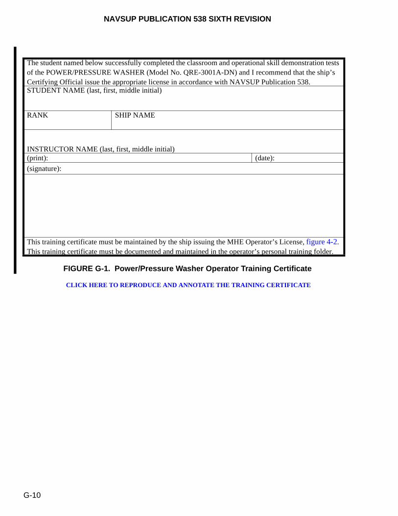
NAVSUP PUBLICATION 538 SIXTH REVISION
G-10
FIGURE G-1. Power/Pressure Washer Operator Training Certificate
The student named below successfully completed the classroom and operational skill demonstration tests of the POWER/PRESSURE WASHER (Model No. QRE-3001A-DN) and I recommend that the ship’s Certifying Official issue the appropriate license in accordance with NAVSUP Publication 538. STUDENT NAME (last, first, middle initial)
RANK SHIP NAME
INSTRUCTOR NAME (last, first, middle initial) (print): (date):
(signature):
This training certificate must be maintained by the ship issuing the MHE Operator’s License, figure 4-2. This training certificate must be documented and maintained in the operator’s personal training folder.
CLICK HERE TO REPRODUCE AND ANNOTATE THE TRAINING CERTIFICATE

(Insert Classification of TMDER Here) CLASSIFICATION
NAVSUP TECHNICAL MANUAL DEFICIENCY/EVALUATION REPORT (TMDER)
INSTRUCTION: Continue on 8 1/2" x 11" paper if additional space is needed.
1. USE THIS REPORT TO INDICATE DEFICIENCIES, PROBLEMS, AND RECOMMENDATIONS RELATION TO PUBLICATIONS.2. FOR CLASSIFIED TMDERS, SEE OPNAVINST 5510H FOR MAILING CLASSIFIED TMDERS.
1. PUB NO.
NAVSUP PUB 538
2. VOL/PART 3. REV. NO./DATE OR TM CH. NO./DATE
Rev 6/1 April 2012
4. SYSTEM/EQUIPMENT IDENTIFICATION
5. TITLE
Management of Materials Handling Equipment (MHE) and Shipboard Mobile Support Equipment (SMSE)
6. REPORT CONTROL NUMBER
7. RECOMMENDED CHANGES TO PUBLICATION
PAGENO.A
PARA-GRAPH
BC. RECOMMENDED CHANGES AND REASONS
8. ORIGINATOR'S NAME AND WORK CENTER (Please Print)
9. DATE 10. DSN/COMM NO. 11. TRANSMITTED TO
12. SHIP HULL NO. AND/OR STATION ADDRESS (Do Not Abbreviate)
To expedite a response also mail a copy to: Naval Surface Warfare Center, Indian Head Division Detachment Picatinny, Buidling 458, Whittemore Avenue, Picatinny Arsenal, NJ 07806-5000, Attn: Code G13.

PLEASE CLOSE WITH TAPE - DO NOT STAPLE - THANK YOU
FOLD HERE -------------------------------------------------------------------------------------------------------------------------------------------DEPARTMENT OF THE NAVY
=================
Official Business
COMMANDERNAVSUP WEAPON SYSTEMS SUPPORTATTN: CODE 83415450 CARLISLE PIKEP.O. BOX 2020MECHANICSBURG, PA 17055-0788
-------------------------------------------------------------------------------------------------------------------------------------------FOLD HERE