Embed Size (px)
Citation preview
ManageUPS
NET
User Manual
ManageUPS
NET
User Manual
ManageUPS
™
NET
User Instruction Manual
UPS Network Managment Adapter
Offering complete remote managagability via WEB, SNMP, or Telnet
IMPORTANT SAFETY INSTRUCTIONS
SAVE THESE INSTRUCTIONS.
Please read and save these instructions. This manual contains important instructions for the ManageUPS
NET
Adapter. Follow these instructions during the unpacking, installation and maintenance of the. If you have a problem with the ONEAC ManageUPS
NET
, please refer to this manual before calling the Technical Support Department.
Licenses and Trademarks
ONEAC, ON Series,and MopUPS are all registered trademarks and ManageUPS is a trademark of ONEAC Corporation, A Chloride Power Protection Company. All other trademarks, product and corporate names are the property of their respective owners.
Entire contents copyright ©2000 ONEAC Corporation, a Chloride Power Protection Company. All rights reserved. Reproduction in whole or in part without permission is prohibited. All information subject to change without notice.
913-316-1 Rev. C 9/00
ONEAC USA27944 North Bradley RoadLibertyville, IL 60048-9700USA
ONEAC EUROPE18 & 20 Blacklands Way Abingdon Business ParkAbingdon, Oxfordshire OX14 1DYUnited Kingdom
Telephone: (847) 816-6000 Toll Free: (800) 327-8801Facsimile: (847) 680-5124
Telephone: +44 (0) 1235 534721Facsimile: +44 (0) 1235 534197
Contents
ManageUPS
NET
User Instruction Manual i
Contents
Introduction ....................................................................................... 1What's New in Version 2.6 ........................................................... 1Total Manageability ..................................................................... 2Using This Manual ....................................................................... 3
Technical Support ............................................................................... 3Specifications ..................................................................................... 4Installation ......................................................................................... 5
Physical Installation Internal Adapter ............................................ 5External Adapter .......................................................................... 6
Rear Panel Description ........................................................................ 7Quick Start ......................................................................................... 9
Features ....................................................................................... 9Configuring TCP/IP Settings ......................................................... 9
Using SNMP ..................................................................................... 12Overview ................................................................................... 12Access ....................................................................................... 12Traps ......................................................................................... 12Configuring Your NMS .............................................................. 13
Configuring MopNET Server ............................................................. 13Configuring Email Settings ............................................................... 15
Overview ................................................................................... 15Email Settings ............................................................................ 15
Web Interface .................................................................................. 16Overview ................................................................................... 16Accessing the ManageUPSnet Using a Web Browser .................. 17Custom Links ............................................................................. 18On-line Help .............................................................................. 18
Telnet and Terminal Console ............................................................ 18Overview ................................................................................... 18Accessing the Console Using Terminal ....................................... 18Accessing the Console Using Telnet ........................................... 19
File Transfers .................................................................................... 20Overview ................................................................................... 20Upgrading Firmware .................................................................. 21Uploading Files .......................................................................... 28Downloading Files ...................................................................... 33
Security ............................................................................................ 35Overview ................................................................................... 35
Contents
ii ManageUPS
NET
User Instruction Manual
User Names, Passwords, and Community Names ........................36Ports ..........................................................................................36Security Summary Table .............................................................37
Appendix A: Configuration File Description .......................................38Appendix B: Sample Configuration File .............................................42Appendix C: File Descriptions ............................................................45Appendix D: SNMP MIBS ...................................................................47
About UPS MIBS (RFC1628) ........................................................47RFC1628 Support .......................................................................48ONEAC Private Extension MIB .....................................................55
Appendix E: RFC1213 and Generic Trap Support ...............................58Generic Trap - PDU Support .......................................................63
Appendix F: Pass-through Mode .......................................................64
Introduction
ManageUPS
NET
User Instruction Manual 1
Introduction
Thank you for purchasing ManageUPS
NET
. The ManageUPS
NET
Network manageability adapter is designed for use with ONEAC’s ON Series UPS products. ManageUPS
NET
based on the current state of RFC 1628 and provides an open approach to management of network AC power.
What's New in Version 2.6 A Name change
ManageUPS
NET
Adapter (formerly known as the SNMP adapter) reflects the increased manageability options for WEB, Telnet and Out-Of-Band accessibility in addition to SNMP based management.
FTP/TFTP
Configuration files and embedded firmware of the adapter itself can now be updated over the network — simplifying maintenance for remote populations.
Email messaging
In addition to sending SNMP traps on UPS fault conditions, the ManageUPS adapter can also send email notification. This provides fault messaging to locations beyond SNMP NMS consoles, including any email destination.
Improved Telnet
Telnet menus have been expanded. They not only provide SNMP and network configuration, but offer access to all UPS information and control parameters available via SNMP or WEB interfaces.
Introduction
2 ManageUPS
NET
User Instruction Manual
CONSOLE Session Support
CONSOLE session support for remote access via modem or terminal server provides Out-Of-Band access to all adapter and UPS configuration options.
Network shutdown
ManageUPS
NET
supports the MopNET protocol which allows MopUPS
®
shutdown software to monitor the UPS over a TCP/IP network.
The new MopNET connection option extends the flexibility of MopUPS for applications where:
• Serial communications between PC and UPS are not an option due to distance or communications port availability.
• Different shutdown priorities or OS environments exist for computers sharing a common UPS power source.
Total Manageability
The ability to monitor and manage a UPS and power conditioning system is an integral part of any remote network connectivity configuration.
ONEAC offers a variety of UPS interface accessory kits that provide for local monitoring and automated control of servers or processors running popular network operating environments: NetWare, OS/2, LAN Server, Banyan or UNIX (SCO, SUN/OS, Solaris, HP UX, AIX and others). The ManageUPS
NET
adapter was developed especially for those who need a higher level of support for integrated, in-band manageability of dedicated communications switching systems via the world-wide web (web), Telnet or SNMP-based network management utilities.
Technical Support
ManageUPS
NET
User Instruction Manual 3
Using This Manual
This manual uses the following conventions:
• Individual hard key names that appear on the keyboard are in Helvetica font, small capital letters, enclosed in brackets. For example:
[ENTER], [TAB], [RIGHT ARROW], [LEFT ARROW]
• Words, phrases, abbreviations, and computer commands typed into a type-in field on the monitor screen are shown in bold courier font. For example: cd /usr/tmp
NOTE:
Type each character of the words and use punctuation as it appears in the text of this manual.
• Computer screen display messages are shown in regular courier font. For example:
Press any key to continue
Technical Support
ONEAC offers 24-hour technical support. Contact ONEAC Technical Services: at (800) 327-8801 (option 3), in Europe: +44 (0) 1235 534721.email: [email protected]
NOTE:
All calls received before 7 a.m. or after 7p.m. Central Standard Time are forwarded to a beeper. An ONEAC Technical Support Representative will return your call within one half hour between 5 p.m. and 10 p.m. Central Standard Time. Except for emergencies, calls received between 10 p.m. and 7 a.m. will be returned during normal business hours.
Please check with ONEAC Technical Services before attempting to repair or return any ONEAC product. If ManageUPS
NET
needs repair or replacement, ONEAC Technical Services issues a Return Material Authorization (RMA) number along with instructions on how to return the adapter.
Specifications
4 ManageUPS
NET
User Instruction Manual
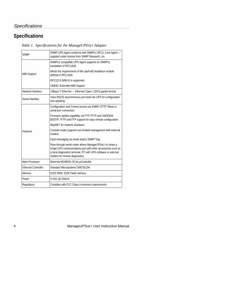
Specifications
Table 1. Specifications for the ManageUPS
NET
Adapter
SNMPSNMP UPS Agent conforms with SNMPv1 RFCs. Core Agent — supplied under license from SNMP Research, Inc.
MIB Support
SNMPv1 compatible UPS Agent supports an SNMPv1 translation of RFC1628
Meets the requirements of the upsFullCompliance module defined in RFC1628
RFC1213 (MIB-II) is supported
ONEAC Extended MIB Support
Network Interface 10Base-T Ethernet — Ethernet Class 1 (DIX) packet format
Serial InterfaceUses RS232 asynchronous port built into UPS for configuration and updating.
Features
Configuration and Control access via SNMP, HTTP, Telnet or serial port connection.
Firmware update capability via FTP, TFTP and XMODEM BOOTP, TFTP and FTP support for easy remote configuration.
MopNET for network shutdown.
Console mode supports out-of-band management with external modem.
Fault messaging via email and/or SNMP Trap.
Pass-through serial router allows ManageUPS
NET
to share a single UPS communications port with other accessories such as a local diagnostics terminal, PC with UPS software or external modem for remote diagnostics.
Main Processor Motorola MC68331 32 bit
µ
Controller
Ethernet Controller Standard Microsystems SMC91C94
Memory 512K RAM, 512K Flash memory
Power 5 VDC @ 200mA
Regulatory Complies with FCC Class A emission requirements
Installation
ManageUPS
NET
User Instruction Manual 5
Installation
This section will take you through the process of installing the ManageUPS
NET
in the interface slot of an ON Series UPS.
NOTE:
Shielded 10Base-T cable should be used for both internal and external versions of manageUPS.
Physical Installation Internal Adapter
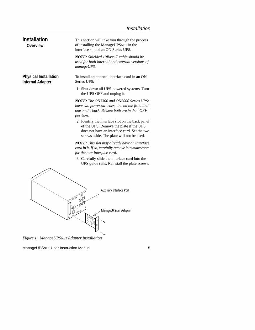
To install an optional interface card in an ON Series UPS:
1. Shut down all UPS-powered systems. Turn the UPS OFF and unplug it.
NOTE:
The ON3300 and ON5000 Series UPSs have two power switches, one on the front and one on the back. Be sure both are in the “OFF” position.
2. Identify the interface slot on the back panel of the UPS. Remove the plate if the UPS does not have an interface card. Set the two screws aside. The plate will not be used.
NOTE:
This slot may already have an interface card in it. If so, carefully remove it to make room for the new interface card.
3. Carefully slide the interface card into the UPS guide rails. Reinstall the plate screws.
Figure 1. ManageUPS
NET
Adapter Installation
Overview
Auxiliary Interface Port
ManageUPSNET Adapter
Installation
6 ManageUPS
NET
User Instruction Manual
4. Refer to specific instructions provided in the Accessory Kit.
5. Plug the UPS in and turn it ON.
External Adapter
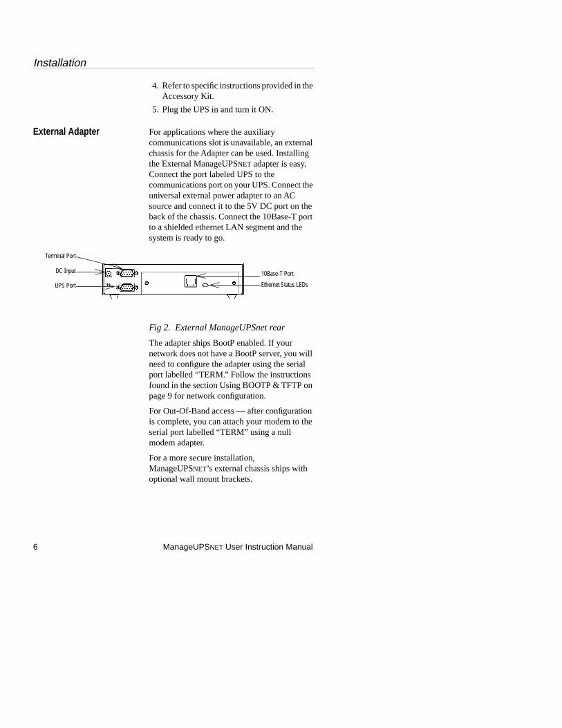
For applications where the auxiliary communications slot is unavailable, an external chassis for the Adapter can be used. Installing the External ManageUPS
NET
adapter is easy. Connect the port labeled UPS to the communications port on your UPS. Connect the universal external power adapter to an AC source and connect it to the 5V DC port on the back of the chassis. Connect the 10Base-T port to a shielded ethernet LAN segment and the system is ready to go.
Fig 2. External ManageUPSnet rear
The adapter ships BootP enabled. If your network does not have a BootP server, you will need to configure the adapter using the serial port labelled “TERM.” Follow the instructions found in the section Using BOOTP & TFTP on page 9 for network configuration.
For Out-Of-Band access — after configuration is complete, you can attach your modem to the serial port labelled “TERM” using a null modem adapter.
For a more secure installation, ManageUPS
NET
’s external chassis ships with optional wall mount brackets.
DC Input
UPS Port
10Base-T Port
Ethernet Status LEDs
Terminal Port
Rear Panel Description
ManageUPS
NET
User Instruction Manual 7
Insert the tabs of the brackets into the slots on the bottom of the chassis. Tighten the screws provided and your adapter is ready for a neat and secure installation.
NOTE:
Make sure all earth connections are made to a single earth reference. Multiple earth potentials can result in ground currents flowing through serial cables that will interfere with the unit operation or damage circuits within the unit.
Rear Panel Description
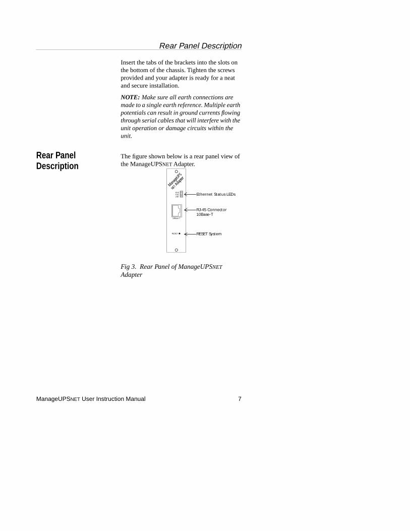
The figure shown below is a rear panel view of the ManageUPS
NET
Adapter.
Fig 3. Rear Panel of ManageUPS
NET
Adapter
RESET
NET Adap
ter
ManageU
PS
RXD
LNKTXD Ethernet Status LEDs
RJ-45 Connector10Base-T
RESET System
10Base-T
Rear Panel Description
8 ManageUPS
NET
User Instruction Manual
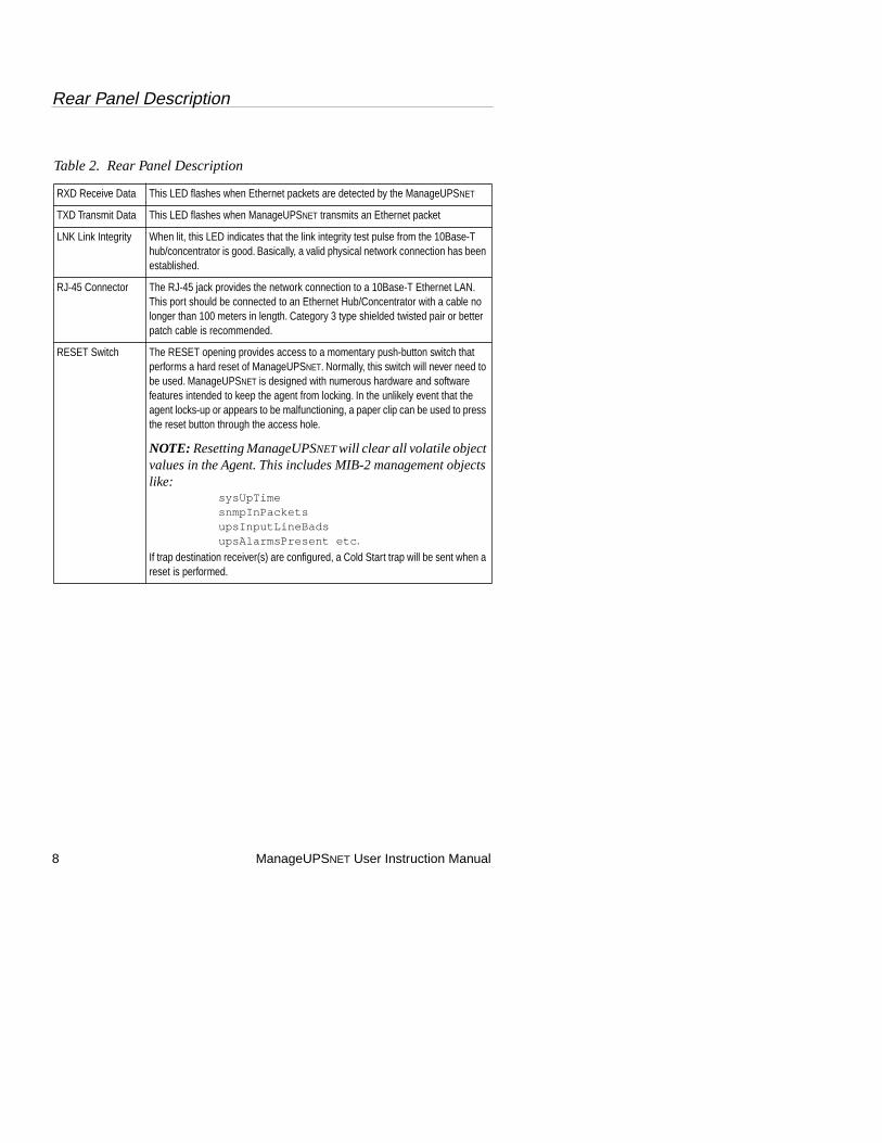
Table 2. Rear Panel Description
RXD Receive Data This LED flashes when Ethernet packets are detected by the ManageUPS
NET
TXD Transmit Data This LED flashes when ManageUPS
NET
transmits an Ethernet packet
LNK Link Integrity When lit, this LED indicates that the link integrity test pulse from the 10Base-T hub/concentrator is good. Basically, a valid physical network connection has been established.
RJ-45 Connector The RJ-45 jack provides the network connection to a 10Base-T Ethernet LAN. This port should be connected to an Ethernet Hub/Concentrator with a cable no longer than 100 meters in length. Category 3 type shielded twisted pair or better patch cable is recommended.
RESET Switch The RESET opening provides access to a momentary push-button switch that performs a hard reset of ManageUPS
NET
. Normally, this switch will never need to be used. ManageUPS
NET
is designed with numerous hardware and software features intended to keep the agent from locking. In the unlikely event that the agent locks-up or appears to be malfunctioning, a paper clip can be used to press the reset button through the access hole.
NOTE:
Resetting ManageUPS
NET
will clear all volatile object values in the Agent. This includes MIB-2 management objects like:
sysUpTime snmpInPackets upsInputLineBads upsAlarmsPresent etc
. If trap destination receiver(s) are configured, a Cold Start trap will be sent when a reset is performed.
Quick Start
ManageUPS
NET
User Instruction Manual 9
Quick Start
Features
ManageUPS
NET
offers many features that ease network management tasks of ON Series UPS systems. These features include:
• Extensive UPS Configuration and Control functions available from an integrated web interface.
• Email messages sent via SMTP in response to UPS related events.
• An RS232 based console interface.
• A remote console available via Telnet.
• BOOTP and TFTP support.
• An integrated FTP server which allows for scripted configuration and firmware upgrades for multiple cards.
Configuring TCP/IP Settings
Using BOOTP & TFTP
Using BOOTP, which is enabled by default, ManageUPS
NET
can obtain all of its network configuration information from a BOOTP
server. This information includes: IP address, subnet mask, default gateway and an optional configuration file.
To configure the adapter using BOOTP, follow these instructions:
1. Create an entry for this adapter on your BOOTP server based on the MAC address assigned to ManageUPS
NET
. This address can be found on the back panel of the adapter.
The following is a sample BOOTP server entry. Depending on the BOOTP server in use, your actual entry will be different but the concept will be the same.
ups-01:sm=255.255.255.0:
ip=198.186.180.63:
Quick Start
10 ManageUPS
NET
User Instruction Manual
ht=ethernet:ha=002082000179:
gw=198.186.180.1:hd=/tftpboot:
bf=adapter.cfg:vm=rfc1048
This configuration sets the SNMP adapter interface as follows:
IP address: 198.186.180.63
Subnet mask: 255.255.255.0
Default gateway: 198.186.180.1
Configuration file: /tftpboot/adapter.cfg
NOTE:
This configuration file is optional. See Appendix A for more details on the file format.
2. Connect the adapter to the network.
3. The BOOTP server will provide the network settings to the adapter upon bootup.
4. If a configuration file was specified, then the adapter will attempt to transfer that file from a TFTP server residing on the same server as the BOOTP server. The adapter will configure itself based on the settings specified in the configuration file.
5. The adapter can now be configured remotely using the Web interface, Telnet or FTP. The default user name is “
admin
”, the default password is “
admin
”.
Using a Terminal and the Serial Port
To configure the ManageUPS
NET
adapter using the serial port, follow these instructions:
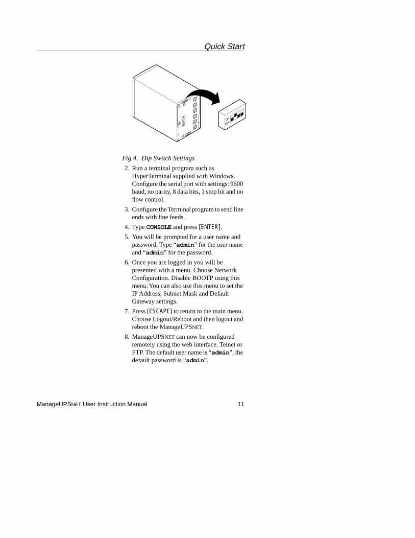
1. Connect the port
NET
adapter into an ONEAC ON Series UPS, make sure the DIP switches, located on the back panel of the UPS are in the following positions: Dip switch1 is in the down (OFF) position and DIP switch 2 is in the up (ON) position.
Quick Start
ManageUPS
NET
User Instruction Manual 11
Fig 4. Dip Switch Settings
2. Run a terminal program such as HyperTerminal supplied with Windows. Configure the serial port with settings: 9600 baud, no parity, 8 data bits, 1 stop bit and no flow control.
3. Configure the Terminal program to send line ends with line feeds.
4. Type
CONSOLE
and press
[ENTER]
.
5. You will be prompted for a user name and password. Type “
admin
” for the user name and “
admin
” for the password.
6. Once you are logged in you will be presented with a menu. Choose Network Configuration. Disable BOOTP using this menu. You can also use this menu to set the IP Address, Subnet Mask and Default Gateway settings.
7. Press
[ESCAPE]
to return to the main menu. Choose Logout/Reboot and then logout and reboot the ManageUPS
NET
.
8. ManageUPS
NET
can now be configured remotely using the web interface, Telnet or FTP. The default user name is “
admin
”, the default password is “
admin
”.
ON
OFF
Using SNMP
12 ManageUPS
NET
User Instruction Manual
Using SNMP
Overview
The Simple Network Management Protocol (SNMP) provides a means for transferring data between two devices. A Management Information Base (MIB) and MIB Object Identifiers (OIDs) are used by the two devices as the means of communication. The MIBs supported by the ManageUPS
NET
are described in Appendix D: SNMP MIBS and Appendix E: RFC1213 and Generic Trap Support.
The ManageUPS
NET
can also send SNMP messages, called traps, to up to 10 Network Management Stations (NMS) when various UPS related events are detected by the ManageUPS
NET
.
Access
The ManageUPS
NET
allows for up to 10 SNMP communities. By default, the ManageUPS
NET
allows any NMS to GET (private community) and SET (public community) ManageUPS
NET
settings. This allows you to use SNMP to manage the ManageUPS
NET
immediately, however, this does not provide any security.
You can use the Console, via serial link or Telnet, or the web interface to change these access settings.
Traps
The ManageUPS
NET
can send UPS alarms or informational messages (traps) to up to 10 SNMP destinations (usually NMS stations). Each trap destination must include the community name and the IP address of the NMS station that is to receive the trap.
You can use the
Console
, via serial link or Telnet, or the web interface to configure trap destinations.
Configuring MopNET Server
ManageUPS
NET
User Instruction Manual 13
Configuring Your NMS
This section describes the process for configuring your SNMP based NMS to see and communicate with your UPS over the network.
NOTE:
This section addresses basic network management software issues. Due to the variety of SNMP network management software available, detailed information (e.g., specific NMS platforms) is not included in this manual.
In summary, the MIB supplied with this product is compatible with most current SNMPv1 management tools.
Adding the MIB to your NMS
1. Follow the normal procedure for adding a MIB to your NMS MIB database. MIBs are provided on the ManageUPS
NET
CD-ROM. See Appendix D, page 47 for a description of the MIBS supported.
2. Set the IP address of the ManageUPS
NET
within your NMS.
3. (Optional) Add an icon to represent the UPS on your NMS’s network map. Icons for UPSs are provided on the CD-ROM.
You are now ready to communicate with ManageUPS
NET
using MIB access utilities supplied with your NMS software. If the installed UPS is configured to send traps to your NMS, you will receive traps when extraordinary events occur at the UPS. For example, pulling the plug on the UPS will cause the upsTrapOnBattery trap to be sent to your NMS.
Configuring MopNET Server
The ManageUPS
NET
adapter hosts a MopNET server. The MopNET server offers added flexibility for multiple server shutdown. A MopNET client is integrated in MopUPS. The MopNET server can support up to 100 computers (multiple MopUPS license codes

Configuring MopNET Server
14 ManageUPS
NET
User Instruction Manual
required) without degrading the performance of the other entities in ManageUPS (SNMP, WEB or Telnet agents).
Fig 5. MopNET Configuration Page
The MopNET server authorizes client access based on the unique license key offered by the client at login. This activity is transparent to the system administrator and is typically configured in the MopUPS entity installed on the target PC. To enable multiple MopUPS clients on a single MopNET host, you will need multiple valid license keys. Each CD media distribution of MopUPS ships with a unique license key. Under this scenario, multiple client connections are administered automatically.
Multi-client license keys can be purchased separately at a lower cost per client to enable additional connections from the original MopUPS CD media key. Multi-license keys can be used when additional copies of MopUPS are installed, or entered directly into ManageUPS in the NETWORK menu.
Contact your UPS reseller or ONEAC for more information on multi-client license keys.
Configuring Email Settings
ManageUPS
NET
User Instruction Manual 15
Configuring Email Settings
Overview
The ManageUPS
NET
can send an email message to up to 5 recipients when it detects various UPS related events. These are the same events that trigger the ManageUPS
NET
to send an SNMP trap. This feature is particularly useful in systems that do not use SNMP and therefore will not receive traps.
A typical message will look like this:
The UPS @ Computer Lab #3 is running on battery power.
Line Voltage: 0 VAC
Time On Battery: 5 sec.
Estimated Minutes Remaining: 15
--------------------UPS Information---------------------
Model: ON400A
Serial Number: 9987-4444
Name: Web UPS
Contact: Joe (x456)
Location: Computer Lab #3
Attached Devices: Primary Web Server
URL: http://198.186.180.200
-----------------------------------------------------------------------------------------------
Email Settings The ManageUPSNET uses SMTP to send email messages, so it is important to have the SMTP settings configured properly. The following parameters are required for configuring email notification of events:
• SMTP Server IP Address: The IP address of the SMTP host server that the UPS unit will use when sending email messages in response to an event.

Web Interface
16 ManageUPSNET User Instruction Manual
NOTE: This is the IP address NOT the host name, the ManageUPSNET does NOT support DNS.
• SMTP Port: The port that the SMTP server is listening on, this is usually port 25.
• Message From: The from email address that the UPS unit will use when sending email messages in response to an event.
• Domain: The name of the domain that the UPS unit belongs to.
• Email Notification (Enabled/Disabled): Email notification is disabled by default.
• On Battery Message Delay: The amount of time, in seconds, to delay email notification of an On Battery Event.
• On Battery Repeat Delay: The amount of time, in seconds, to delay repeating an email notification of an On Battery Event.
• Email Destinations: The names and email addresses of up to 5 recipients.
You can use the Console, via serial link or Telnet, or the web interface to configure SMTP settings as well as email destinations.
Web Interface
Overview The ManageUPSNET allows management of the UPS and the ManageUPSNET configuration via a Web interface. The client workstation requires only a standard web browser, with JavaScript enabled, to manage the ManageUPSNET. Microsoft Internet Explorer 3.0 or later or Netscape 3.0 or later will work.
Web Interface
ManageUPSNET User Instruction Manual 17
Accessing the ManageUPSNET Using a Web Browser
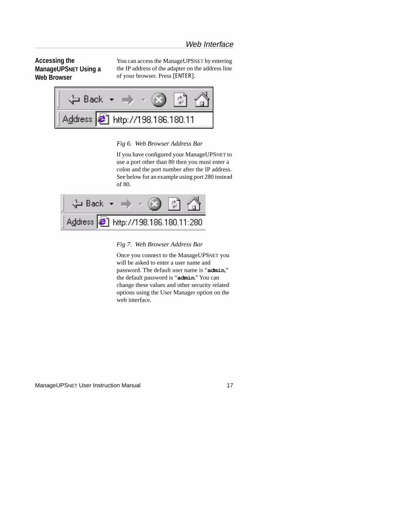
You can access the ManageUPSNET by entering the IP address of the adapter on the address line of your browser. Press [ENTER].
Fig 6. Web Browser Address Bar
If you have configured your ManageUPSNET to use a port other than 80 then you must enter a colon and the port number after the IP address. See below for an example using port 280 instead of 80.
Fig 7. Web Browser Address Bar
Once you connect to the ManageUPSNET you will be asked to enter a user name and password. The default user name is “admin ,” the default password is “admin .” You can change these values and other security related options using the User Manager option on the web interface.

Telnet and Terminal Console
18 ManageUPSNET User Instruction Manual
Custom Links The ManageUPSNET allows four different types of user-definable links for linking the ManageUPSNET to other UPSs, networked devices, internal support and graphics. The four types of links are:
On-line Help The ManageUPSNET has its own internal help pages, they can be accessed by clicking the “?” on the title bar.
Telnet and Terminal Console
Overview The ManageUPSNET allows management of the UPS and the ManageUPSNET configuration via a Console which is available serially or over a network using Telnet.
Accessing the Console Using Terminal
You can access your ManageUPSNET serially using a terminal or an emulator:
1. Connect the ManageUPSNET to an available serial port on your computer using the cable supplied (ONEAC part# CA-9F).
2. When inserting the ManageUPSNET into an ONEAC ON Series UPS then make sure the DIP switches located on the back panel of
Table 3. Type of Links
Chain Links
Used to create a chain between multiple UPS’s in a system. For example, if you have 10 adapters and this adapter was the 5th, you can use the two links to connect to adapters 4 and 6. This chain can then be repeated on the other adapters.
Custom Links Used for linking to other web sites or other networked devices.
Support LinksUsed for linking to internal or external support sites a user of this adapter may need.
Graphic LinksUsed for configuring the URLs of the graphic image displayed on the top of the web interface.
Telnet and Terminal Console
ManageUPSNET User Instruction Manual 19
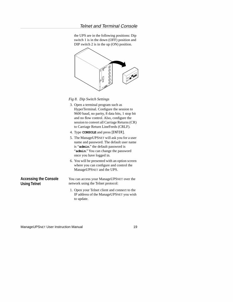
the UPS are in the following positions: Dip switch 1 is in the down (OFF) position and DIP switch 2 is in the up (ON) position.
Fig 8. Dip Switch Settings
3. Open a terminal program such as HyperTerminal. Configure the session to 9600 baud, no parity, 8 data bits, 1 stop bit and no flow control. Also, configure the session to convert all Carriage Returns (CR) to Carriage Return LineFeeds (CRLF).
4. Type CONSOLE and press [ENTER].5. The ManageUPSNET will ask you for a user
name and password. The default user name is “admin .” the default password is “admin .” You can change the password once you have logged in.
6. You will be presented with an option screen where you can configure and control the ManageUPSNET and the UPS.
Accessing the Console Using Telnet
You can access your ManageUPSNET over the network using the Telnet protocol:
1. Open your Telnet client and connect to the IP address of the ManageUPSNET you wish to update.
ON
OFF
File Transfers
20 ManageUPSNET User Instruction Manual
2. The ManageUPSNET will ask you for a user name and password. The default user name is “admin ”, the default password is “admin .” You can change the password once you have logged in.
3. You will be presented with an option screen where you can configure and control the ManageUPSNET and the UPS.
File Transfers
Overview The ManageUPSNET allows for all of its files to be downloaded, except the firmware file, and a few key files to be uploaded (see Appendix C, page 45). The files that can be uploaded are the firmware file, configuration file, default settings file and a graphic file.
When a firmware file (firmware.gz) is uploaded to the ManageUPSNET, the code running on the adapter is updated. This allows you to easily keep up with the latest features and patches.
When a configuration file (adapter.cfg) is uploaded to the ManageUPSNET, the adapter configuration is updated to the settings specified in the file. This allows for all or some of the configuration settings to be modified at once. The configuration file format is defined in Appendix A: Configuration File Description.
When the default settings file (adapter.def) or a graphic file (oemgraphic1.jpg) get uploaded they replace the existing files. The default settings file contains the settings that get applied when the adapter is told to reset using the web, telnet or serial interfaces. The graphics files can be used to display custom graphics on the main page of the web interface.
The following sections discuss the various ways of transferring files to the ManageUPSNET.
File Transfers
ManageUPSNET User Instruction Manual 21
Upgrading Firmware Firmware File Description
Firmware is the software running inside the ManageUPSNET that allows it to monitor the UPS and perform all of the tasks described in this manual. The file that is uploaded to the adapter is actually a compressed file containing the firmware file. This file is then decompressed, validated and then written over the firmware currently running on the adapter.
Obtaining the latest Firmware File
To obtain the latest firmware for your ManageUPSNET contact ONEAC Technical Support (see Technical Support, page 3).
Upgrade Using FTP
The following steps should be taken when updating the ManageUPSNET using FTP.
1. Obtain the latest firmware (for example firmware260x.gz) from ONEAC and place it in a directory named \Manageupsnet on your PC. The PC must be connected to the network.
2. Ensure that the adapter is also attached to the network and has already been configured with an IP address, Subnet Mask and a Default Gateway. The FTP server must also be enabled.
3. Open a Command Prompt. Change to the \Manageupsnet directory containing the latest firmware file.
4. Open an FTP session by typing “ftp ” at the command line.
5. Connect to the ManageUPSNET by typing “open xxx.xxx.xxx.xxx yy ” where “xxx.xxx.xxx.xxx ” represents the IP address of the ManageUPSNET and “yy ” represents the FTP server port. If the port
File Transfers
22 ManageUPSNET User Instruction Manual
was not changed from the default of 21 then supplying the port in the command line is optional.
6. The ManageUPSNET will ask you for a user name and password. The default user name is “admin” the default password is “admin.” Yours may be different.
7. Type the command “ftp> bin ” and the press [ENTER]. The ManageUPSNET should respond with “ftp> 200 Command okay .”
8. Type in the command “put gz firmware.gz ,” where is the local name and firmware.gz is the name it will be given on the ManageUPSNET, press [ENTER]. The ManageUPSNET should respond with the following:
200Command okay.
150File status okay; about to open data connection for /.
250Requested file action okay, completed.
221Service closing control connection
132209bytes sent in 27.07 seconds (4.88 Kbytes/sec)
9. The adapter will take approximately 1 minute to update the adapter with the new firmware.
Upgrade Using Web Interface and TFTP
The following steps should be followed when updating the ManageUPSNET using the Web interface and TFTP.
1. Obtain the latest firmware(firmware.gz) from ONEAC and place it in a directory on your TFTP server.
File Transfers
ManageUPSNET User Instruction Manual 23
2. Ensure that the adapter is also attached to the network and has already been configured with an IP address, Subnet Mask and a Default Gateway. The FTP server must also be enabled.
3. Open your browser, point it to the adapter.
4. The ManageUPSNET will ask you for a user name and password. The default user name is “admin ” the default password is “admin ”. Yours may be different.
5. Click the Administration option on the left side of the web interface. This will expand the Administra ˇon sub-menu.
6. Click the File Transfer option on the Administration sub-menu.
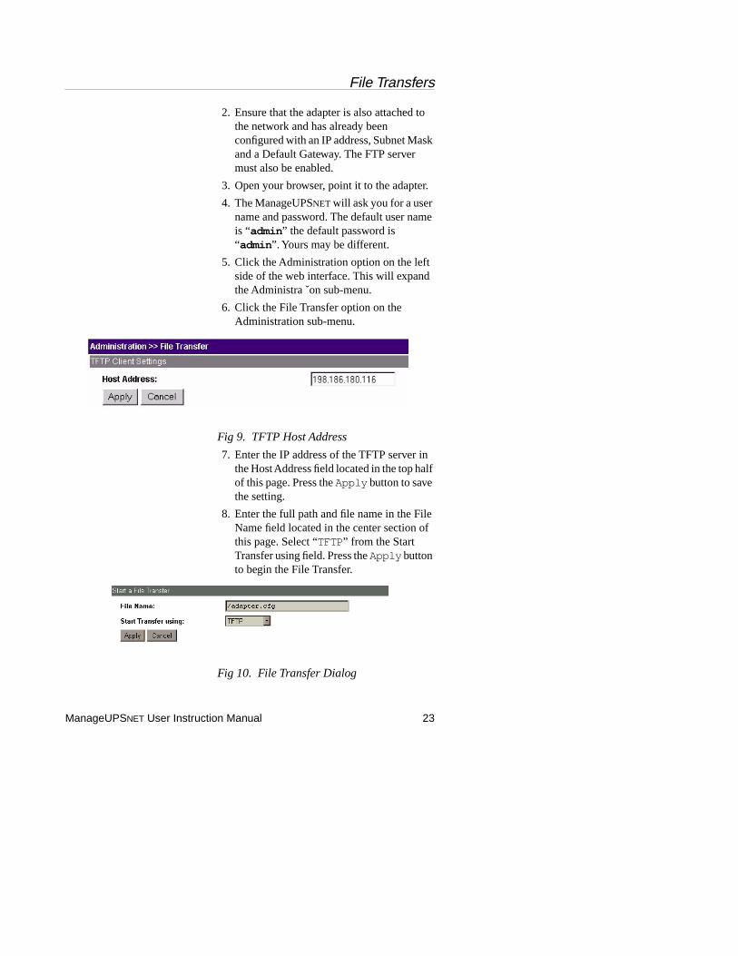
Fig 9. TFTP Host Address
7. Enter the IP address of the TFTP server in the Host Address field located in the top half of this page. Press the Apply button to save the setting.
8. Enter the full path and file name in the File Name field located in the center section of this page. Select “TFTP” from the Start Transfer using field. Press the Apply button to begin the File Transfer.
Fig 10. File Transfer Dialog
File Transfers
24 ManageUPSNET User Instruction Manual
9. The Web server will provide status pages during the file transfer. When the update is complete the browser will be redirected back to the main web interface page.
Upgrade Using the Console and TFTP
The following steps should be followed when updating the ManageUPSNET using the Telnet or Serial Console and TFTP.
1. Obtain the latest firmware(firmware260x.gz) from ONEAC and place it in a directory on your TFTP server.
2. Ensure that the adapter is attached to the network and has already been configured with an IP address, Subnet Mask and a Default Gateway. The FTP server must also be enabled.
3. If you are using Telnet go to step 4, if you are using serial communications then skip to step 5.
4. Open your Telnet client and connect to the IP address of the ManageUPSNET adapter you wish to update. Skip to step 9.
5. Connect the ManageUPSNET to an available serial port on your computer
6. Open a terminal program such as HyperTerminal. Configure the session to 9600 baud, no parity, 8 data bits, 1 stop bit and no flow control. Also configure the session to convert all Carriage Returns (CR) to Carriage Return LineFeeds (CRLF).
7. Type CONSOLE and press [ENTER].8. The ManageUPSNET will ask you for a user
name and password. The default user name is “admin ” the default password is “admin .” Yours may be different.
File Transfers
ManageUPSNET User Instruction Manual 25
9. Select the Administration option from the Main Menu. This will display the Administration Menu.
10.Select the File Transfer option. This will display the File Transfer Menu.
11.Use this screen to enter the IP address of the TFTP server and the full path and file name of the firmware file.
12.Select the Initiate File Transfer using TFTP option to begin the File Transfer.
13.The Console will provide status information during the file transfer. The adapter will reset when the update is complete and your connection will be lost. You must wait about 30 seconds before reconnecting.
Upgrade Using XMODEM
The following steps should be taken when updating the ManageUPSNET using the Serial Console and XMODEM.
1. Obtain the latest firmware(firmware.gz) from ONEAC and place it in a directory named \Manageupsnet on your PC. The PC must be connected to the network.
2. Connect the ManageUPSNET to an available serial port on your computer using the cable supplied (ONEAC part# CA-9F).
3. Open a terminal program such as HyperTerminal. Configure the session to 9600 baud, no parity, 8 data bits, 1 stop bit and no flow control. Also configure the session to convert all Carriage Returns (CR) to Carriage Return LineFeeds (CRLF).
4. Type CONSOLE and press [ENTER].5. The ManageUPSNET will ask you for a user
name and password. The default user name is “admin ” the default password is “admin .” Yours may be different.
File Transfers
26 ManageUPSNET User Instruction Manual
6. Select the Administration option from the Main Menu. This will display the Administration Menu.
7. Select the File Transfer option. This will display the File Transfer Menu.
8. Select the Initiate File Transfer using XMODEM option to begin the File Transfer.
9. Using the terminal program, select the firmware file (the firmware.gz file you received from ONEAC) to transfer via XMODEM.
10.The Console will provide status information during the file transfer. The adapter will reset when the update is complete and your connection will be lost. You must wait about 30 seconds before reconnecting.
Scripting mass firmware updates using FTP
This section describes how to script a mass firmware update from a Windows NT/95/98 computer using FTP.
1. Obtain the latest firmware(firmware.gz) from ONEAC and place it in a directory named \Manageupsnet on your PC. The PC must be connected to the network.
2. Ensure that all of the adapters you wish to update are also attached to the network and have already been configured with an IP address, Subnet Mask and a Default Gateway. The FTP server on each adapter must also be enabled.
3. Using the text editor, such as Notepad, create an FTP script file using the following as an example.
File Transfers
ManageUPSNET User Instruction Manual 27
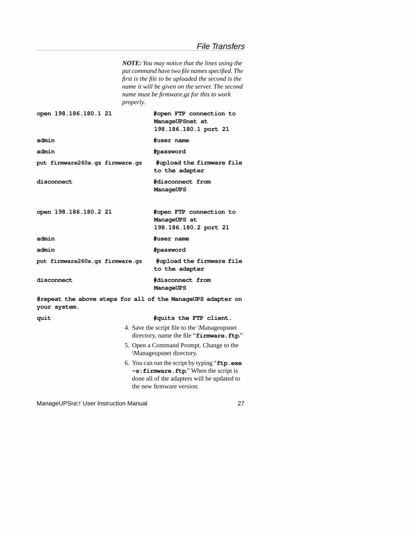
NOTE: You may notice that the lines using the put command have two file names specified. The first is the file to be uploaded the second is the name it will be given on the server. The second name must be firmware.gz for this to work properly.
open 198.186.180.1 21 #open FTP connection to ManageUPSnet at 198.186.180.1 port 21
admin #user name
admin #password
put firmware260x.gz firmware.gz #upload the firmware file to the adapter
disconnect #disconnect from ManageUPS
open 198.186.180.2 21 #open FTP connection to ManageUPS at 198.186.180.2 port 21
admin #user name
admin #password
put firmware260x.gz firmware.gz #upload the firmware file to the adapter
disconnect #disconnect from ManageUPS
#repeat the above steps for all of the ManageUPS adapter on your system.
quit #quits the FTP client.
4. Save the script file to the \Manageupsnet directory, name the file “firmware.ftp .”
5. Open a Command Prompt. Change to the \Manageupsnet directory.
6. You can run the script by typing “ftp.exe -s:firmware.ftp .” When the script is done all of the adapters will be updated to the new firmware version.
File Transfers
28 ManageUPSNET User Instruction Manual
Uploading Files Some of the files listed in Appendix C, page 45, can be uploaded to the ManageUPSNET using several different methods. This section describes the four methods which can be used to perform file uploads.
Upload Configuration File Using BOOTP and TFTP
This is described in section 5.2.1 Using BOOTP & TFTP.
Upload File Using FTP
1. Ensure that the adapter is attached to the network and has already been configured with an IP address, Subnet Mask and a Default Gateway. The FTP server must also be enabled.
2. Open a Command Prompt.
3. Change to the directory containing the file(s) to upload.
4. Open an FTP session by typing “ftp ” at the command line.
5. Connect to the ManageUPSNET by typing “open xxx.xxx.xxx.xxx yy ” where “xxx.xxx.xxx.xxx ” represents the IP address of the ManageUPSNET and “yy ” represents the FTP server port. If the port was not changed from the default of 21 then supplying the port in the command line is optional.
6. The ManageUPSNET will ask you for a user name and password. The default user name is “admin ” the default password is “admin .” Yours may be different.
7. Type the command “ftp> bin ” and the press [ENTER]. The ManageUPSNET should respond with “ftp> 200 Command okay .”

File Transfers
ManageUPSNET User Instruction Manual 29
8. Type in the command “put filename1 filename2 ”, where filename1 is the local name of the file and filename2 is the name of a file described in Appendix C, page 45, press [ENTER]. The ManageUPSNET should respond with the following:
200Command okay.
150File status okay; about to open data connection for /.
250Requested file action okay, completed
1406bytes sent in 0.00 seconds (1400000 Kbytes/sec)
Upload File Using Web Interface and TFTP
The following steps should be taken when uploading files to the ManageUPSNET using the web interface and TFTP.
1. Place the files you wish to upload in a directory on your TFTP server. A list of uploadable files are described in Appendix C page 45.
2. Ensure that the adapter is attached to the network and has already been configured with an IP address, Subnet Mask and a Default Gateway. The FTP server must also be enabled.
3. Open your browser, point it to the adapter.
4. The ManageUPSNET will ask you for a user name and password. The default user name is “admin” default password is “admin .” Yours may be different.
5. Click the Administration option on the left side of the web interface. This will expand the Administration sub-menu.
6. Click the File Transfer option on the Administration sub-menu.
File Transfers
30 ManageUPSNET User Instruction Manual
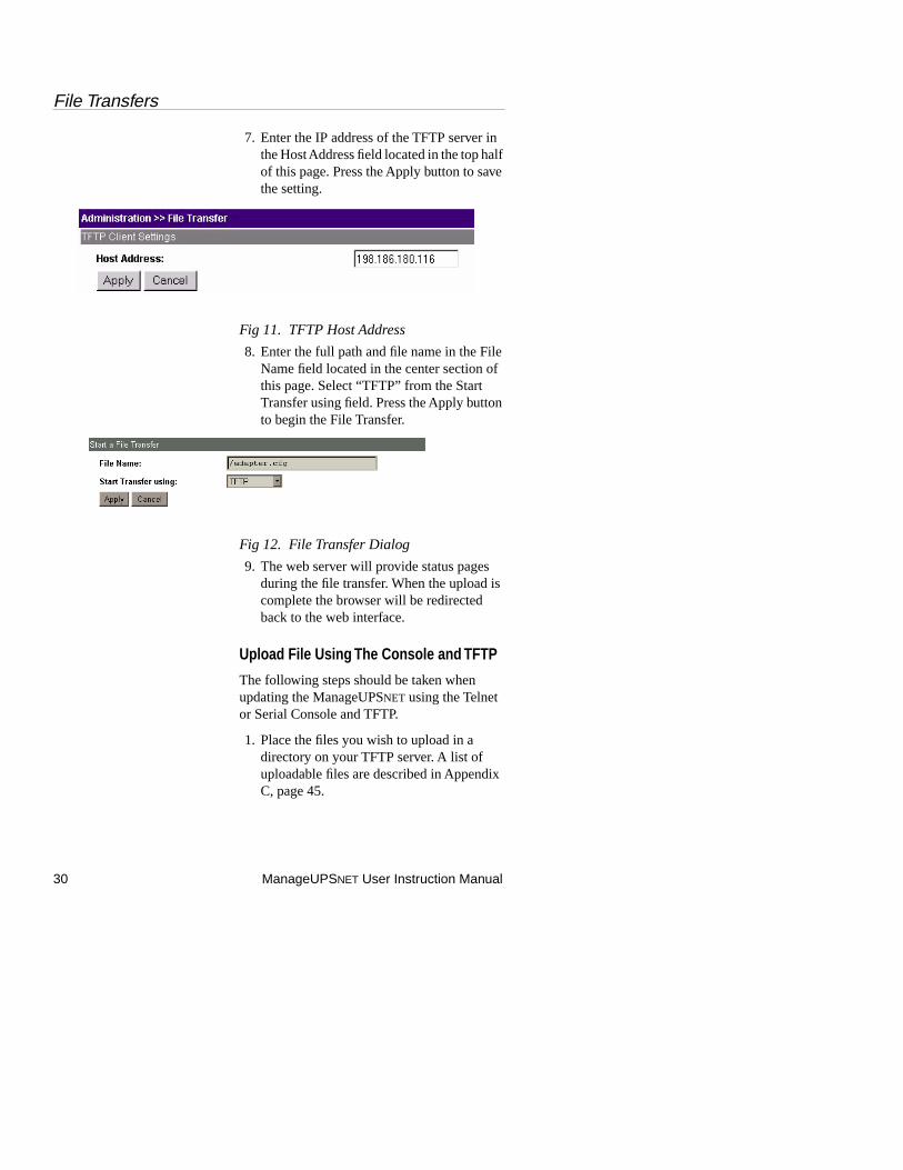
7. Enter the IP address of the TFTP server in the Host Address field located in the top half of this page. Press the Apply button to save the setting.
Fig 11. TFTP Host Address
8. Enter the full path and file name in the File Name field located in the center section of this page. Select “TFTP” from the Start Transfer using field. Press the Apply button to begin the File Transfer.
Fig 12. File Transfer Dialog
9. The web server will provide status pages during the file transfer. When the upload is complete the browser will be redirected back to the web interface.
Upload File Using The Console and TFTP
The following steps should be taken when updating the ManageUPSNET using the Telnet or Serial Console and TFTP.
1. Place the files you wish to upload in a directory on your TFTP server. A list of uploadable files are described in Appendix C, page 45.
File Transfers
ManageUPSNET User Instruction Manual 31
2. Ensure that the adapter is attached to the network and has already been configured with an IP address, Subnet Mask and a Default Gateway. The FTP server must also be enabled.
3. If you are using Telnet go to step 4, if you are using serial communications then skip to step 5.
4. Open your Telnet client and connect to the IP address of the ManageUPSNET adapter you wish to update. Skip to step 9.
5. Connect the ManageUPSNET to an available serial port on your computer using the cable supplied (ONEAC part# CA-9F).
6. Open a terminal program such as HyperTerminal. Configure the session to 9600 baud, no parity, 8 data bits, 1 stop bit and no flow control. Also configure the session to convert all Carriage Returns (CR) to Carriage Return LineFeeds (CRLF).
7. Type CONSOLE and press [ENTER].8. The ManageUPSNET will ask you for a user
name and password. The default user name is “admin ” the default password is “admin .” Yours may be different.
9. Select the Administration option from the Main Menu. This will display the Administration Menu.
10.Select the File Transfer option. This will display the File Transfer Menu.
11.Use this screen to enter the IP address of the TFTP server and the full path and file name.
12.Select the Initiate File Transfer using TFTP option to begin the File Transfer.
13.The Console will provide status information during the file transfer. The adapter will reset when the update is
File Transfers
32 ManageUPSNET User Instruction Manual
complete and your connection will be lost. You must wait about 30 seconds before reconnecting.
Scripting mass file uploads using FTP
This section describes how to script mass file uploads from a Windows NT/95/98 computer using FTP.
1. Place all of the files you wish to upload into a directory named \Manageupsnet on your PC. The PC must be connected to the network.
2. Ensure that all of the adapters you wish to update are also attached to the network and have already been configured with an IP address, Subnet Mask and a Default Gateway. The FTP server on each adapter must also be enabled.
3. Using the text editor, such as Notepad, create an FTP script file using the following as an example.
NOTE: You may notice that the lines using the put command have two file names specified. The first is the file to be uploaded the second is the name it will receive on the server. The second name must be one of the files listed in Appendix C, page 45.
open 198.186.180.1 21 #open FTP connection to ManageUPS at 198.186.180.1 port 21
admin #user name
admin #password
put adapter01.cfg adapter.cfg #upload a generic config file to the adapter
put adapter02.cfg adapter.cfg #upload an adapter specific config file to the adapter
File Transfers
ManageUPSNET User Instruction Manual 33
put adapter02.def adapter.def #upload a default settings file to the adapter
disconnect #disconnect from adapter
open 198.186.180.2 21 #open FTP connection to ManageUPS at 198.186.180.1 port 21
admin #user name
admin #password
put adapter01.cfg adapter.cfg #upload a generic config file to the adapter
put adapter03.cfg adapter.cfg #upload an adapter specific config file to the adapter
put adapter02.def adapter.def #upload a default settings file to the adapter
disconnect #disconnect from ManageUPS
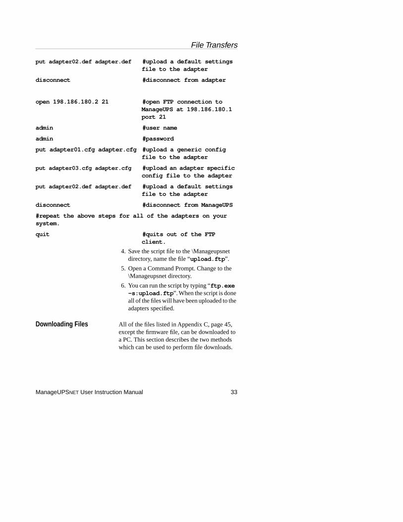
#repeat the above steps for all of the adapters on your system.
quit #quits out of the FTP client.
4. Save the script file to the \Manageupsnet directory, name the file “upload.ftp ”.
5. Open a Command Prompt. Change to the \Manageupsnet directory.
6. You can run the script by typing “ftp.exe -s:upload.ftp ”. When the script is done all of the files will have been uploaded to the adapters specified.
Downloading Files All of the files listed in Appendix C, page 45, except the firmware file, can be downloaded to a PC. This section describes the two methods which can be used to perform file downloads.
File Transfers
34 ManageUPSNET User Instruction Manual
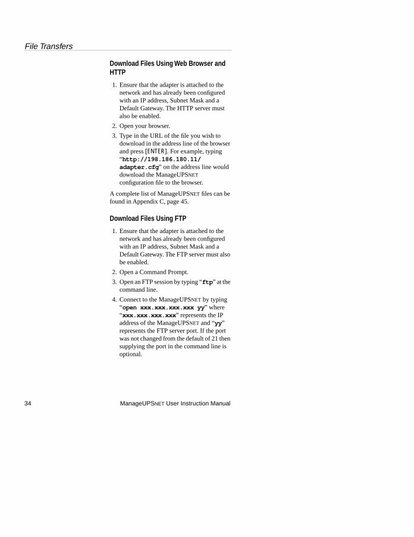
Download Files Using Web Browser and HTTP
1. Ensure that the adapter is attached to the network and has already been configured with an IP address, Subnet Mask and a Default Gateway. The HTTP server must also be enabled.
2. Open your browser.
3. Type in the URL of the file you wish to download in the address line of the browser and press [ENTER]. For example, typing “http://198.186.180.11/adapter.cfg ” on the address line would download the ManageUPSNET configuration file to the browser.
A complete list of ManageUPSNET files can be found in Appendix C, page 45.
Download Files Using FTP
1. Ensure that the adapter is attached to the network and has already been configured with an IP address, Subnet Mask and a Default Gateway. The FTP server must also be enabled.
2. Open a Command Prompt.
3. Open an FTP session by typing “ftp ” at the command line.
4. Connect to the ManageUPSNET by typing “open xxx.xxx.xxx.xxx yy ” where “xxx.xxx.xxx.xxx ” represents the IP address of the ManageUPSNET and “yy ” represents the FTP server port. If the port was not changed from the default of 21 then supplying the port in the command line is optional.

Security
ManageUPSNET User Instruction Manual 35
5. The ManageUPSNET will ask you for a user name and password. The default user name is “admin ” the default password is “admin ”. Yours may be different.
6. Type the command “ftp> bin ” and the press the [ENTER] Key. The ManageUPSNET should respond with “ ftp> 200 Command okay ”.
7. Type in the command “get filename ”, where filename is the name of a file described in Appendix C, page 45, press [ENTER]. The ManageUPSNET should respond with the following:
200 Command okay.
150 File status okay; about to open data connection for /.
226 Closing data connection
6507 bytes received in 2.35 seconds (2.77 Kbytes/sec)
8. The file will be downloaded to your local directory.
Security
Overview The ManageUPSNET provides several security options. The table shown in section 11.4 describes the security options for each interface. The security provided by the ManageUPSNET is generally adequate for most applications. However, any network device which transmits data over a network has a certain amount of exposure. For that reason, the importance of protecting your intranet from external networks (i.e. the internet) with a firewall cannot be underestimated.
Security
36 ManageUPSNET User Instruction Manual
User Names, Passwords, and Community Names
User names and passwords are used for logging into the serial console, Telnet server, FTP server and the web interface. This information, as well as SNMP community names, are transmitted in plain-text over the network. This means that network sniffers can potentially determine the user name and passwords by monitoring network traffic to the device. This, unfortunately, is a limitation of the internet protocols themselves.
Ports You can change the TCP port used by the on board Telnet, FTP and web servers. The default setting for these servers is the well-known port for the specific protocol. If an arbitrary port is used, one between 5000 and 65535, you can effectively “hide” the server. This provides an additional level of security since the port must be known by the user when attempting to connect to the server with client software.
Security
ManageUPSNET User Instruction Manual 37
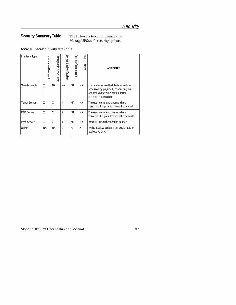
Security Summary Table The following table summarizes the ManageUPSNET’s security options.
Table 4. Security Summary Table
Interface Type
User N
ame/Passw
ord
Changeable Server Port
Server Enable/Disable
Access Com
munities
NM
S IP filters Comments
Serial console X NA NA NA NA this is always enabled, but can only be accessed by physically connecting the adapter to a terminal with a serial communications cable.
Telnet Server X X X NA NA The user name and password are transmitted in plain text over the network.
FTP Server X X X NA NA The user name and password are transmitted in plain text over the network.
Web Server X X X NA NA Basic HTTP authentication is used.
SNMP NA NA X X X IP filters allow access from designated IP addresses only.
Appendix A: Configuration File Description
38 ManageUPSNET User Instruction Manual
Appendix A: Configuration File Description
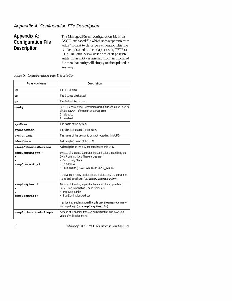
The ManageUPSNET configuration file is an ASCII text based file which uses a “parameter = value” format to describe each entity. This file can be uploaded to the adapter using TFTP or FTP. The table below describes each possible entity. If an entity is missing from an uploaded file then that entity will simply not be updated in any way.
Table 5. Configuration File Description
Parameter Name Description
ip The IP address.
sm The Subnet Mask used.
gw The Default Route used
bootp BOOTP enabled flag – determines if BOOTP should be used to obtain network information at startup time. 0 = disabled1 = enabled
sysName The name of the system.
sysLocation The physical location of this UPS.
sysContact The name of the person to contact regarding this UPS.
identName A descriptive name of the UPS.
identAttachedDevices A description of the devices attached to this UPS.
snmpCommunity0 –••snmpCommunity9
10 sets of 3 tuples, separated by semi-colons, specifying the SNMP communities. These tuples are• Community Name• IP Address• Permissions (READ, WRITE or READ_WRITE)
Inactive community entries should include only the parameter name and equal sign (i.e. snmpCommunity9= ).
snmpTrapDest0••snmpTrapDest9
10 sets of 3 tuples, separated by semi-colons, specifying SNMP trap information. These tuples are• Trap Community• Trap Destination Address
Inactive trap entries should include only the parameter name and equal sign (i.e. snmpTrapDest9= )
snmpAuthenticateTraps A value of 1 enables traps on authentication errors while a value of 0 disables them.
Appendix A: Configuration File Description
ManageUPSNET User Instruction Manual 39
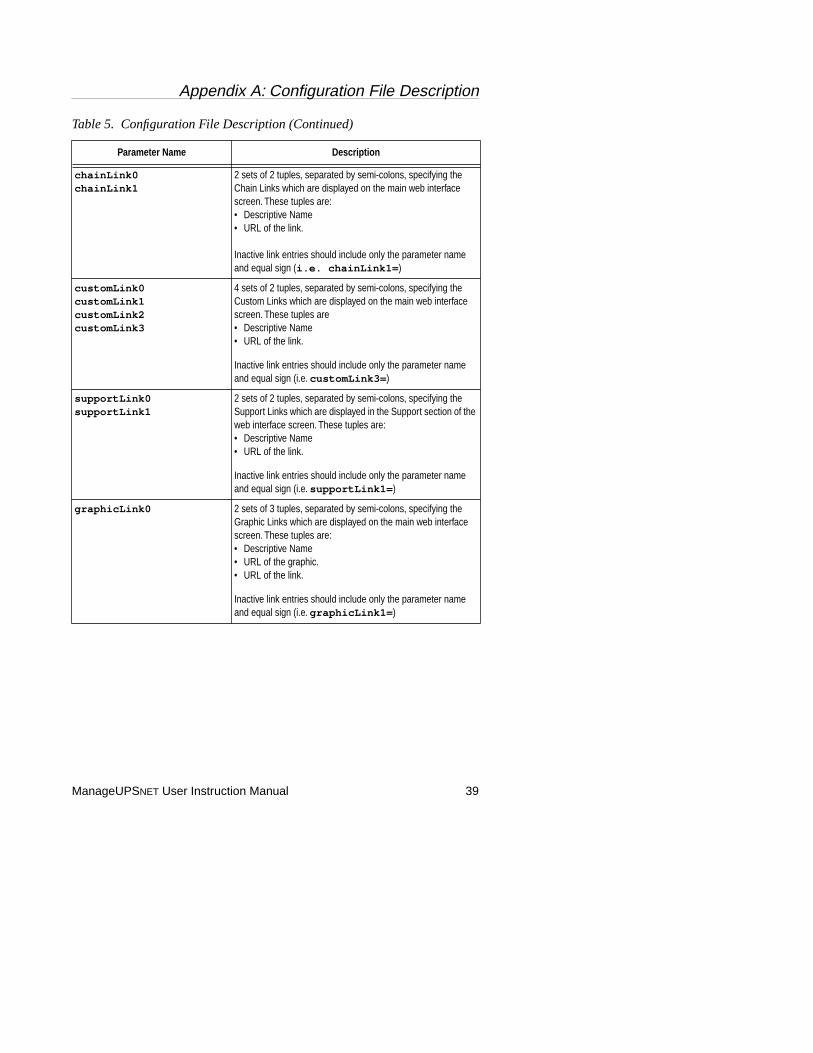
chainLink0chainLink1
2 sets of 2 tuples, separated by semi-colons, specifying the Chain Links which are displayed on the main web interface screen. These tuples are:• Descriptive Name• URL of the link.
Inactive link entries should include only the parameter name and equal sign (i.e. chainLink1= )
customLink0customLink1customLink2customLink3
4 sets of 2 tuples, separated by semi-colons, specifying the Custom Links which are displayed on the main web interface screen. These tuples are• Descriptive Name• URL of the link.
Inactive link entries should include only the parameter name and equal sign (i.e. customLink3= )
supportLink0supportLink1
2 sets of 2 tuples, separated by semi-colons, specifying the Support Links which are displayed in the Support section of the web interface screen. These tuples are:• Descriptive Name• URL of the link.
Inactive link entries should include only the parameter name and equal sign (i.e. supportLink1= )
graphicLink0 2 sets of 3 tuples, separated by semi-colons, specifying the Graphic Links which are displayed on the main web interface screen. These tuples are:• Descriptive Name • URL of the graphic.• URL of the link.
Inactive link entries should include only the parameter name and equal sign (i.e. graphicLink1= )
Table 5. Configuration File Description (Continued)
Parameter Name Description
Appendix A: Configuration File Description
40 ManageUPSNET User Instruction Manual
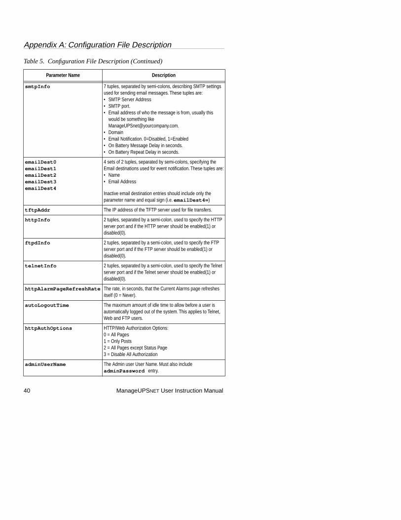
smtpInfo 7 tuples, separated by semi-colons, describing SMTP settings used for sending email messages. These tuples are:• SMTP Server Address• SMTP port.• Email address of who the message is from, usually this
would be something like [email protected].
• Domain• Email Notification. 0=Disabled, 1=Enabled• On Battery Message Delay in seconds.• On Battery Repeat Delay in seconds.
emailDest0emailDest1emailDest2emailDest3emailDest4
4 sets of 2 tuples, separated by semi-colons, specifying the Email destinations used for event notification. These tuples are:• Name • Email Address
Inactive email destination entries should include only the parameter name and equal sign (i.e. emailDest4= )
tftpAddr The IP address of the TFTP server used for file transfers.
httpInfo 2 tuples, separated by a semi-colon, used to specify the HTTP server port and if the HTTP server should be enabled(1) or disabled(0).
ftpdInfo 2 tuples, separated by a semi-colon, used to specify the FTP server port and if the FTP server should be enabled(1) or disabled(0).
telnetInfo 2 tuples, separated by a semi-colon, used to specify the Telnet server port and if the Telnet server should be enabled(1) or disabled(0).
httpAlarmPageRefreshRate The rate, in seconds, that the Current Alarms page refreshes itself (0 = Never).
autoLogoutTime The maximum amount of idle time to allow before a user is automatically logged out of the system. This applies to Telnet, Web and FTP users.
httpAuthOptions HTTP/Web Authorization Options:0 = All Pages1 = Only Posts2 = All Pages except Status Page 3 = Disable All Authorization
adminUserName The Admin user User Name. Must also include adminPassword entry.
Table 5. Configuration File Description (Continued)
Parameter Name Description
Appendix A: Configuration File Description
ManageUPSNET User Instruction Manual 41
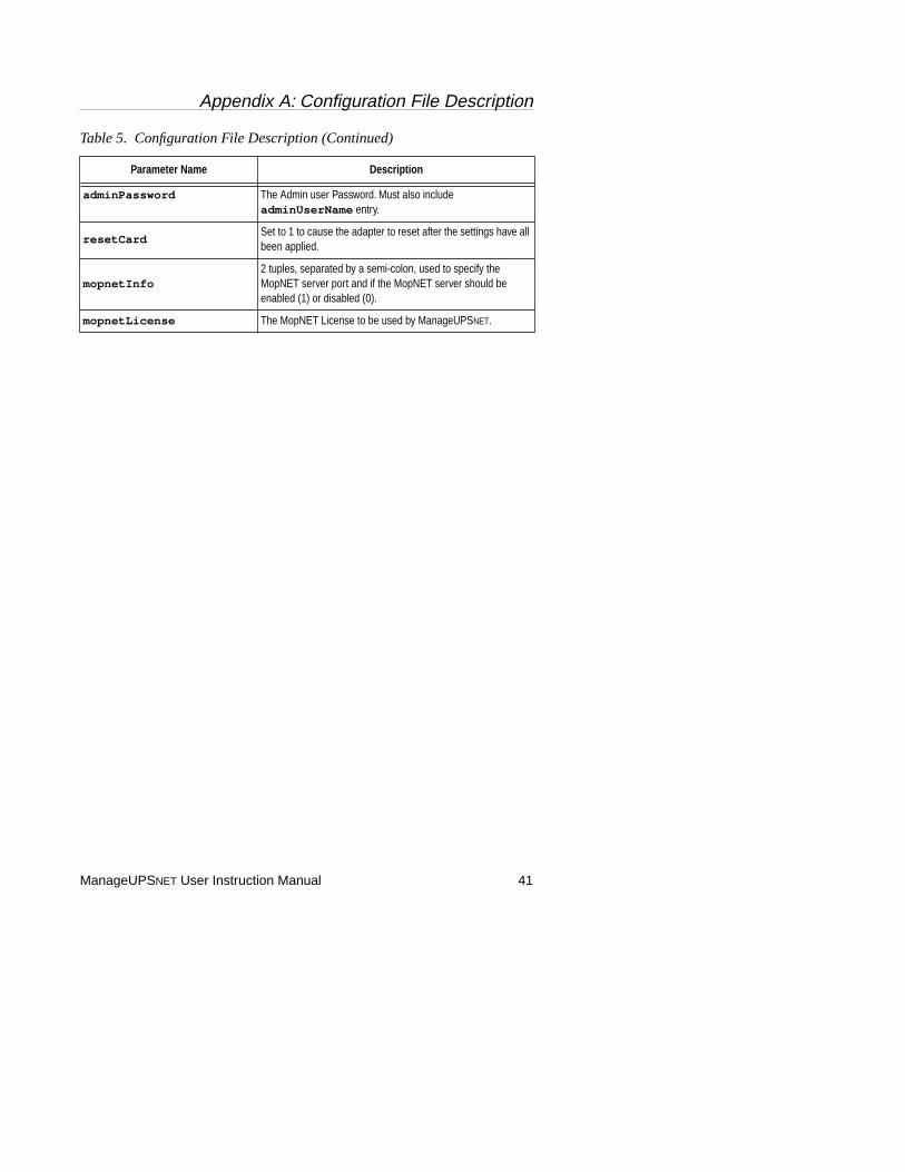
adminPassword The Admin user Password. Must also include adminUserName entry.
resetCardSet to 1 to cause the adapter to reset after the settings have all been applied.
mopnetInfo2 tuples, separated by a semi-colon, used to specify the MopNET server port and if the MopNET server should be enabled (1) or disabled (0).
mopnetLicense The MopNET License to be used by ManageUPSNET.
Table 5. Configuration File Description (Continued)
Parameter Name Description
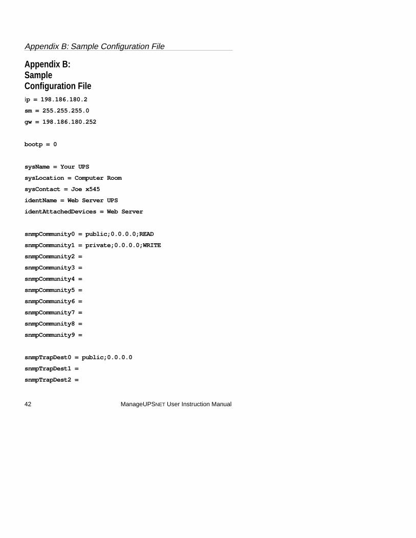
Appendix B: Sample Configuration File
42 ManageUPSNET User Instruction Manual
Appendix B: Sample Configuration Fileip = 198.186.180.2
sm = 255.255.255.0
gw = 198.186.180.252
bootp = 0
sysName = Your UPS
sysLocation = Computer Room
sysContact = Joe x545
identName = Web Server UPS
identAttachedDevices = Web Server
snmpCommunity0 = public;0.0.0.0;READ
snmpCommunity1 = private;0.0.0.0;WRITE
snmpCommunity2 =
snmpCommunity3 =
snmpCommunity4 =
snmpCommunity5 =
snmpCommunity6 =
snmpCommunity7 =
snmpCommunity8 =
snmpCommunity9 =
snmpTrapDest0 = public;0.0.0.0
snmpTrapDest1 =
snmpTrapDest2 =

Appendix B: Sample Configuration File
ManageUPSNET User Instruction Manual 43
snmpTrapDest3 =
snmpTrapDest4 =
snmpTrapDest5 =
snmpTrapDest6 =
snmpTrapDest7 =
snmpTrapDest8 =
snmpTrapDest9 =
snmpAuthenticateTraps = 2
chainLink0 = UPS 1;198.186.180.1
chainLink1 = UPS 3;198.186.180.3
customLink0 = Hub1 supplied by this UPS;198.186.180.10
customLink1 = Router supplied by this UPS;198.186.180.11
customLink2 = Hub2 supplied by this UPS;198.186.180.12
customLink3 = Your Companies Home Page;www.yourcompany.com
supportLink0 = Your Company’s Support Page 1;www.yourcompany.com/support1.html
supportLink1 = Your Company’s Support Page 2;www.yourcompany.com/support2.html
graphicLink0 = ONEAC Home Page;oemgraphic1.jpg;www.oneac.com
smtpInfo = 198.186.180.252;25;[email protected];yourcompany.com;0;30;0
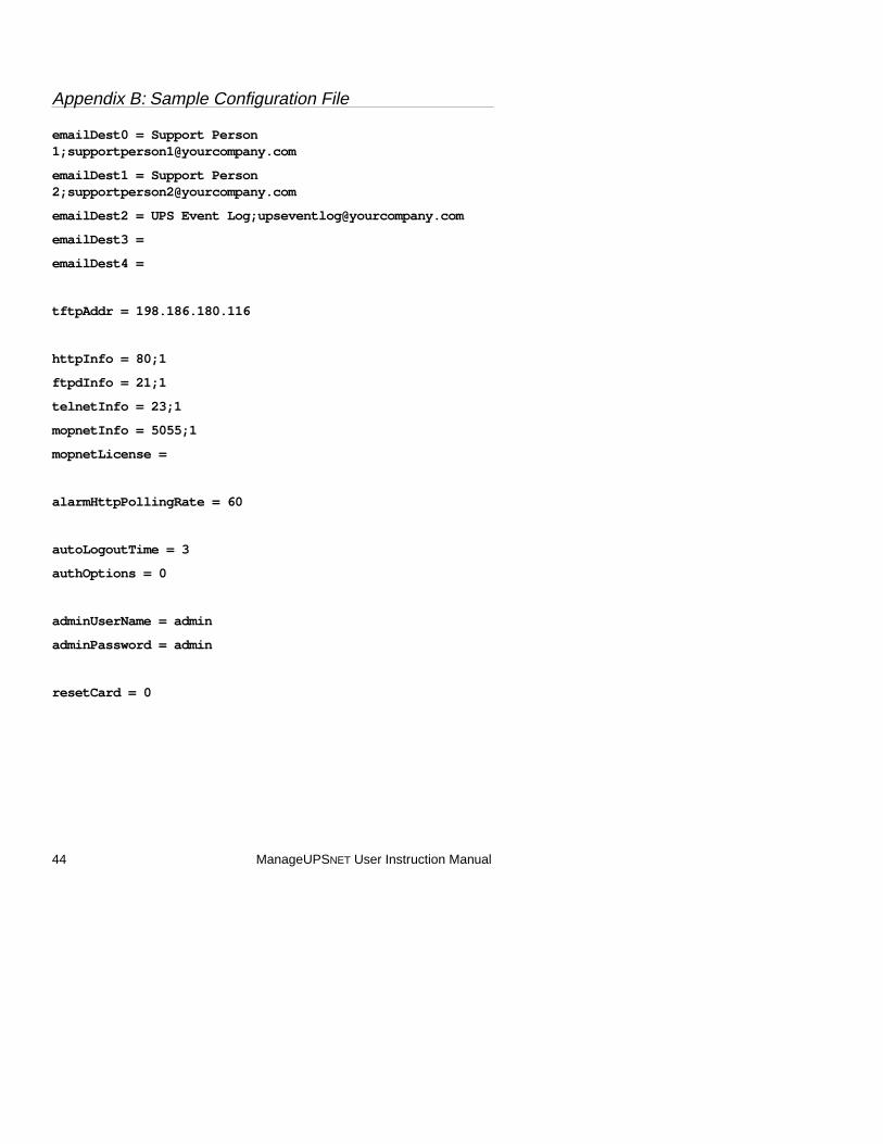
Appendix B: Sample Configuration File
44 ManageUPSNET User Instruction Manual
emailDest0 = Support Person 1;[email protected]
emailDest1 = Support Person 2;[email protected]
emailDest2 = UPS Event Log;[email protected]
emailDest3 =
emailDest4 =
tftpAddr = 198.186.180.116
httpInfo = 80;1
ftpdInfo = 21;1
telnetInfo = 23;1
mopnetInfo = 5055;1
mopnetLicense =
alarmHttpPollingRate = 60
autoLogoutTime = 3
authOptions = 0
adminUserName = admin
adminPassword = admin
resetCard = 0
Appendix C: File Descriptions
ManageUPSNET User Instruction Manual 45
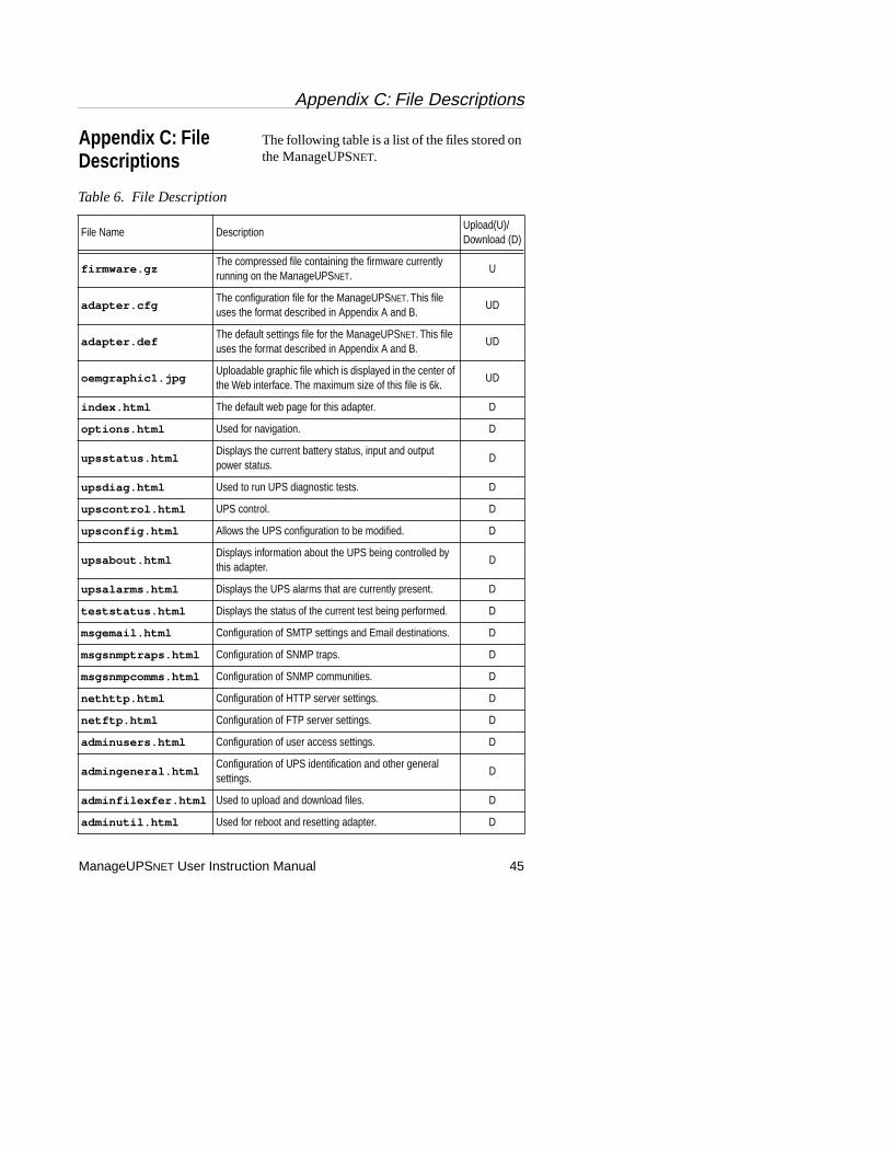
Appendix C: File Descriptions
The following table is a list of the files stored on the ManageUPSNET.
Table 6. File Description
File Name DescriptionUpload(U)/Download (D)
firmware.gzThe compressed file containing the firmware currently running on the ManageUPSNET.
U
adapter.cfgThe configuration file for the ManageUPSNET. This file uses the format described in Appendix A and B.
UD
adapter.defThe default settings file for the ManageUPSNET. This file uses the format described in Appendix A and B.
UD
oemgraphic1.jpgUploadable graphic file which is displayed in the center of the Web interface. The maximum size of this file is 6k.
UD
index.html The default web page for this adapter. D
options.html Used for navigation. D
upsstatus.htmlDisplays the current battery status, input and output power status.
D
upsdiag.html Used to run UPS diagnostic tests. D
upscontrol.html UPS control. D
upsconfig.html Allows the UPS configuration to be modified. D
upsabout.htmlDisplays information about the UPS being controlled by this adapter.
D
upsalarms.html Displays the UPS alarms that are currently present. D
teststatus.html Displays the status of the current test being performed. D
msgemail.html Configuration of SMTP settings and Email destinations. D
msgsnmptraps.html Configuration of SNMP traps. D
msgsnmpcomms.html Configuration of SNMP communities. D
nethttp.html Configuration of HTTP server settings. D
netftp.html Configuration of FTP server settings. D
adminusers.html Configuration of user access settings. D
admingeneral.htmlConfiguration of UPS identification and other general settings.
D
adminfilexfer.html Used to upload and download files. D
adminutil.html Used for reboot and resetting adapter. D
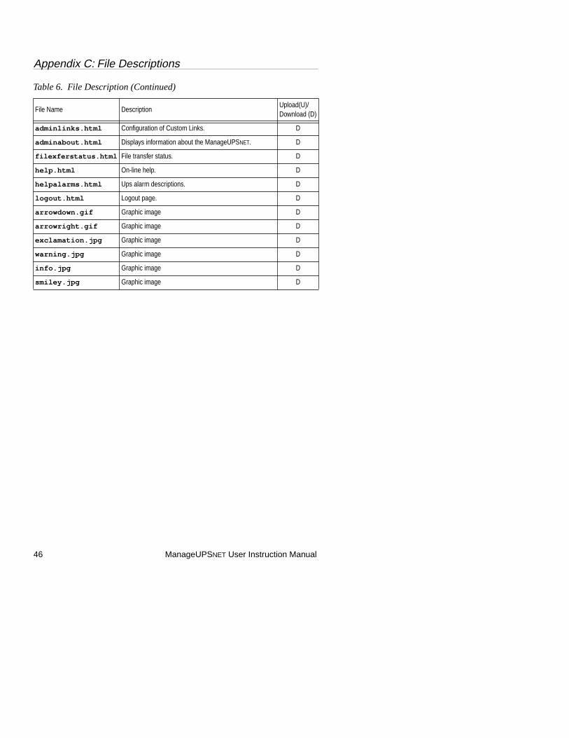
Appendix C: File Descriptions
46 ManageUPSNET User Instruction Manual
adminlinks.html Configuration of Custom Links. D
adminabout.html Displays information about the ManageUPSNET. D
filexferstatus.html File transfer status. D
help.html On-line help. D
helpalarms.html Ups alarm descriptions. D
logout.html Logout page. D
arrowdown.gif Graphic image D
arrowright.gif Graphic image D
exclamation.jpg Graphic image D
warning.jpg Graphic image D
info.jpg Graphic image D
smiley.jpg Graphic image D
Table 6. File Description (Continued)
File Name DescriptionUpload(U)/Download (D)
Appendix D: SNMP MIBS
ManageUPSNET User Instruction Manual 47
Appendix D: SNMP MIBS
About UPS MIBS (RFC1628)
In May 1994, RFC1628 was published. This Request For Comments (RFC) is an Internet Proposed Standard that defines a portion of the Management Information Base (MIB) for use with network protocols in the internet community. In particular, it defines objects for managing uninterruptible power supply (UPS) systems.
This is significant in many ways. The UPS industry has worked together to produce a document that defines the kinds of information and control capabilities that UPSs should be able to support. The benefit to the user is that UPSs that conform to this RFC will be consistent from a management perspective — well almost.
RFC1628 is a MIB that is written with some SNMP Version 2 (SNMPv2) conventions. The reason this was done was to allow for different levels of conformance, which was not an option with SNMPv1. However, among other things, there are references to data types that were not found in SNMPv1. What this means is that the Proposed Standard UPS MIB is not compatible with many SNMPv1 Network Management Stations (NMS).
An SNMPv1 compatible “translation” of RFC1628 is included with the ManageUPSNET Adapter. This MIB is functionally equivalent to RFC1628 and is compatible with SNMPv1 NMS’s. The OID for this MIB (and all it's objects) are the same as RFC1628.
Since the SNMPv1 translation of RFC1628 is not an official document, it does not have an authoritatively assigned name. ONEAC has

Appendix D: SNMP MIBS
48 ManageUPSNET User Instruction Manual
chosen to name the SNMPv1 translation of RFC1628 — 1628_V1.MIB. This is the MIB you will find on the supplied disk in the MIBS directory and it is the MIB you should load into your NMS.
A copy of RFC1628.TXT (the Internet distribution format) has been included on the disk for your information. This is a text file with the UPS MIB written in Abstract Syntax Notation One (ASN.1) format.
One of the fundamental SNMP axioms is — extensibility. The management capabilities of an entity should be extendible. With devices that conform to standard MIBs, this is accomplished with Enterprise Specific MIBs. These are MIBs that individual manufacturers develop to support objects specific to their products. ONEAC supports this concept with the ONEUPSXT.MIB, which is provided on the supplied disk. This MIB is installed in the SNMP Agent and it supports additional interface objects.
Contact ONEAC’s Technical Support Department if you require specific UPS management requirements outside of RFC1628, (see Technical Support, page 3).
RFC1628 Support This section details information about ONEAC’s support of groups and objects in RFC1628. Information presented here is applicable to ONEAC SNMPv1 Agents, Ver 2.0 and greater. Suggestions on the use and interpretation of objects are given. Object defaults and limitations are also discussed.
NOTE: This information is in addition to the definitive descriptions provided in RFC1628.
Appendix D: SNMP MIBS
ManageUPSNET User Instruction Manual 49
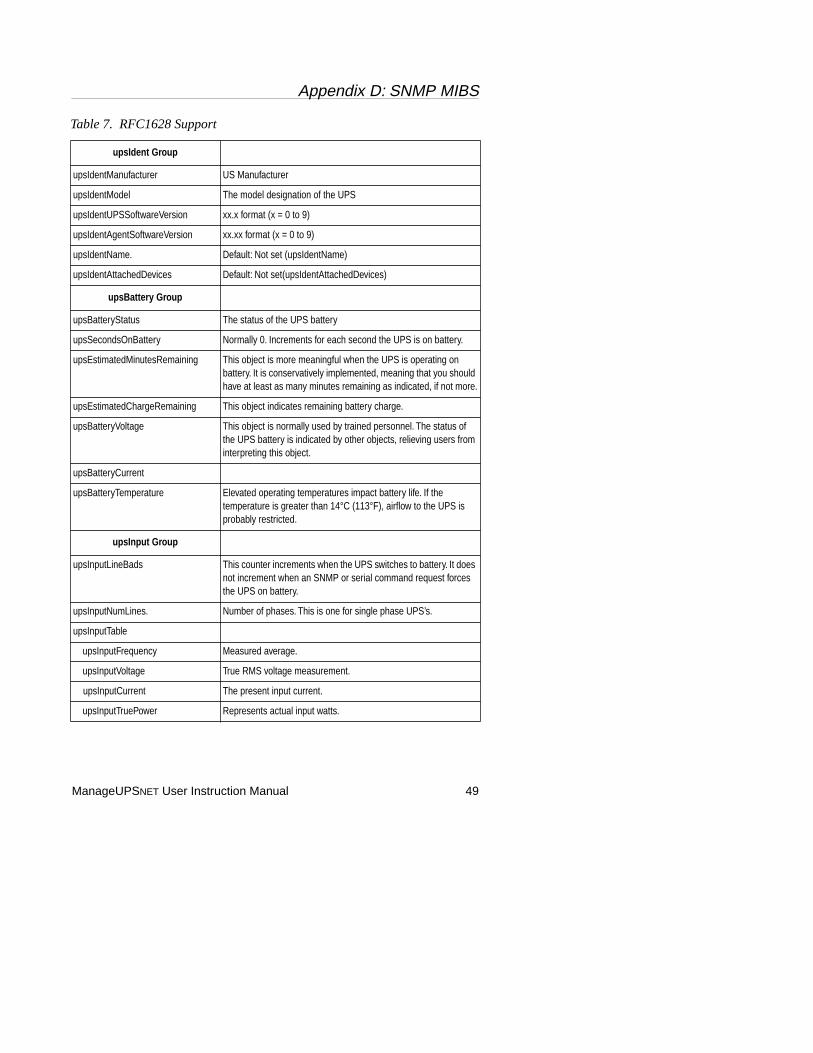
Table 7. RFC1628 Support
upsIdent Group
upsIdentManufacturer US Manufacturer
upsIdentModel The model designation of the UPS
upsIdentUPSSoftwareVersion xx.x format (x = 0 to 9)
upsIdentAgentSoftwareVersion xx.xx format (x = 0 to 9)
upsIdentName. Default: Not set (upsIdentName)
upsIdentAttachedDevices Default: Not set(upsIdentAttachedDevices)
upsBattery Group
upsBatteryStatus The status of the UPS battery
upsSecondsOnBattery Normally 0. Increments for each second the UPS is on battery.
upsEstimatedMinutesRemaining This object is more meaningful when the UPS is operating on battery. It is conservatively implemented, meaning that you should have at least as many minutes remaining as indicated, if not more.
upsEstimatedChargeRemaining This object indicates remaining battery charge.
upsBatteryVoltage This object is normally used by trained personnel. The status of the UPS battery is indicated by other objects, relieving users from interpreting this object.
upsBatteryCurrent
upsBatteryTemperature Elevated operating temperatures impact battery life. If the temperature is greater than 14°C (113°F), airflow to the UPS is probably restricted.
upsInput Group
upsInputLineBads This counter increments when the UPS switches to battery. It does not increment when an SNMP or serial command request forces the UPS on battery.
upsInputNumLines. Number of phases. This is one for single phase UPS’s.
upsInputTable
upsInputFrequency Measured average.
upsInputVoltage True RMS voltage measurement.
upsInputCurrent The present input current.
upsInputTruePower Represents actual input watts.
Appendix D: SNMP MIBS
50 ManageUPSNET User Instruction Manual
upsOutput Group
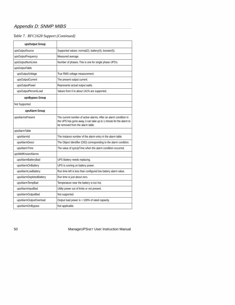
upsOutputSource Supported values: normal(2), battery(4), booster(5).
upsOutputFrequency Measured average.
upsOutputNumLines Number of phases. This is one for single phase UPS’s.
upsOutputTable
upsOutputVoltage True RMS voltage measurement.
upsOutputCurrent The present output current.
upsOutputPower Represents actual output watts.
upsOutputPercentLoad Values from 0 to about 141% are supported.
upsBypass Group
Not Supported
upsAlarm Group
upsAlarmsPresent The current number of active alarms. After an alarm condition in the UPS has gone away, it can take up to 1 minute for the alarm to be removed from the alarm table.
upsAlarmTable
upsAlarmId The instance number of the alarm entry in the alarm table.
upsAlarmDescr The Object Identifier (OID) corresponding to the alarm condition.
upsAlarmTime The value of sysUpTime when the alarm condition occurred.
upsWellKnownAlarms
upsAlarmBatteryBad UPS Battery needs replacing.
upsAlarmOnBattery UPS is running on battery power.
upsAlarmLowBattery Run time left is less than configured low battery alarm value.
upsAlarmDepletedBattery Run time is just about zero.
upsAlarmTempBad Temperature near the battery is too hot.
upsAlarmInputBad Utility power out of limits or not present.
upsAlarmOutputBad Not supported.
upsAlarmOutputOverload Output load power is > 100% of rated capacity.
upsAlarmOnBypass Not applicable.
Table 7. RFC1628 Support (Continued)

Appendix D: SNMP MIBS
ManageUPSNET User Instruction Manual 51
upsAlarm Group (continued)
upsAlarmBypassBad Not applicable.
upsAlarmOutputOffAsRequested Confirmation.
upsAlarmUpsOffAsRequested Confirmation.
upsAlarmChargerFailed Battery charger has failed or its fuse has blown.
upsAlarmUpsOutputOff Confirmation, persistent until output is turned on.
upsAlarmUpsSystemOff UPS shutdown.
upsAlarmFanFailure Not supported.
upsAlarmFuseFailure Input circuit breaker is open or charger fuse has blown.
upsAlarmGeneralFault A UPS fault was detected that is not specifically defined in the standard MIB.
upsAlarmDiagnosticTestFailed A user initiated test has failed.
upsAlarmCommunicationsLost Lost Serial Communications with the UPS.
upsAlarmAwaitingPower Not supported.
upsAlarmShutdownPending A shutdown timer has begun counting.
upsAlarmShutdownImminent Output shutdown will occur in approximately 5 seconds.
upsAlarmTestInProgress A user requested UPS test has begun.
upsTest Group
upsTestId SET this object to the Object Identifier (OID) of the test you want to run.
upsTestSpinLock In order to initiate a UPS test, you must use the upsTestSpinLock as follows: First: GET (read) the current integer value of upsTestSpinLock. Next: SET (write) the integer value just read back to the upsTestSpinLock object and SET upsTestId to the OID of the test you wish to run. It is required that the two SET operations be performed in the same SNMP packet. The purpose of the upsTestSpinLock object is to eliminate the possibility of two Managers simultaneously initiating tests on the same Agent. See the MIB description for more information.
upsTestResultsSummary All valid MIB results are supported. The result of the last test run will be remain in this object.
upsTestResultsDetail If upsTestResultsSummary report doneWarning(2), doneError(3) or aborted(4), then this object will contain a message string detailing more information about the test failure.
upsTestStartTime The value of sysUpTime when the UPS test was initiated.
Table 7. RFC1628 Support (Continued)
Appendix D: SNMP MIBS
52 ManageUPSNET User Instruction Manual
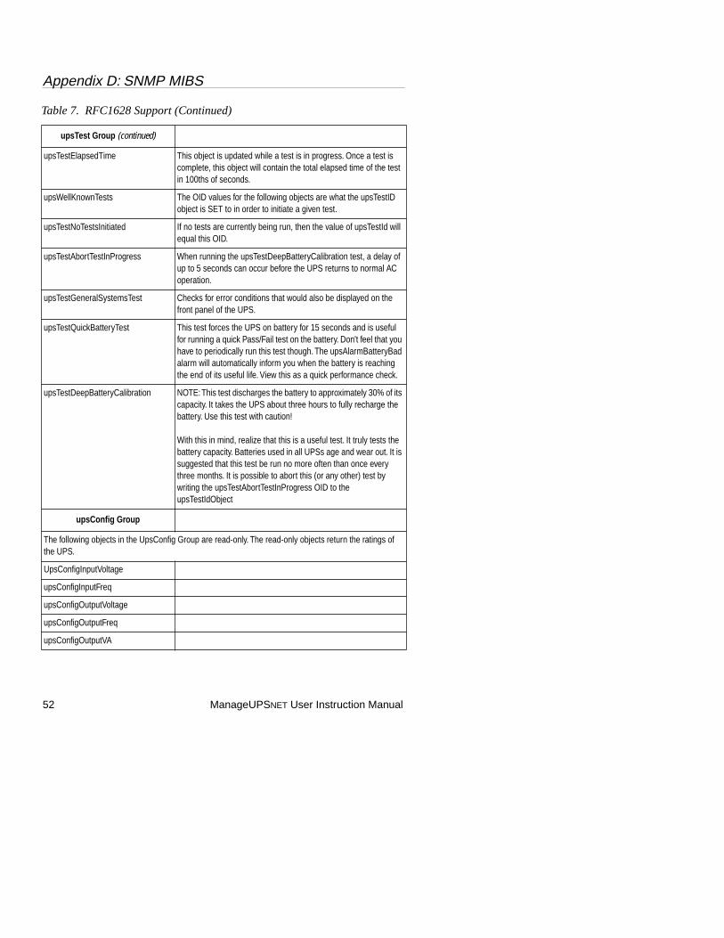
upsTest Group (continued)
upsTestElapsedTime This object is updated while a test is in progress. Once a test is complete, this object will contain the total elapsed time of the test in 100ths of seconds.
upsWellKnownTests The OID values for the following objects are what the upsTestID object is SET to in order to initiate a given test.
upsTestNoTestsInitiated If no tests are currently being run, then the value of upsTestId will equal this OID.
upsTestAbortTestInProgress When running the upsTestDeepBatteryCalibration test, a delay of up to 5 seconds can occur before the UPS returns to normal AC operation.
upsTestGeneralSystemsTest Checks for error conditions that would also be displayed on the front panel of the UPS.
upsTestQuickBatteryTest This test forces the UPS on battery for 15 seconds and is useful for running a quick Pass/Fail test on the battery. Don't feel that you have to periodically run this test though. The upsAlarmBatteryBad alarm will automatically inform you when the battery is reaching the end of its useful life. View this as a quick performance check.
upsTestDeepBatteryCalibration NOTE: This test discharges the battery to approximately 30% of its capacity. It takes the UPS about three hours to fully recharge the battery. Use this test with caution!
With this in mind, realize that this is a useful test. It truly tests the battery capacity. Batteries used in all UPSs age and wear out. It is suggested that this test be run no more often than once every three months. It is possible to abort this (or any other) test by writing the upsTestAbortTestInProgress OID to the upsTestIdObject
upsConfig Group
The following objects in the UpsConfig Group are read-only. The read-only objects return the ratings of the UPS.
UpsConfigInputVoltage
upsConfigInputFreq
upsConfigOutputVoltage
upsConfigOutputFreq
upsConfigOutputVA
Table 7. RFC1628 Support (Continued)

Appendix D: SNMP MIBS
ManageUPSNET User Instruction Manual 53
upsConfig Group (continued)
upsConfigOutputPower
The following objects in the UPSConfig group are read-write.
UpsConfigLowBattTime Valid settings for UPSConfigLowBattTime are between 0 and 99. This is the amount of time before battery exhaustion that the low battery alarm will begin to sound.
upsConfigAudibleStatus Valid settings for UPSConfigAudibleStatus are disabled(1) and enabled(2). One suggested use for this object is to turn off the buzzer before performing a test that would normally cause it to sound.
upsConfigLowVoltageTransferPoint The difference between upsConfigHighVoltageTransferPoint and upsConfigLowVoltageTransferPoint must be 20 volts or greater in a 120 volt UPS, or 40 volts or greater in a 230 volt UPS,
upsConfigHighVoltageTransferPoint
upsControl Group
upsShutdownType The MIB defines two shutdown types: output(1) and system(2).
upsShutdownAfterDelay When set, the UPS will shut down either the UPS output only or the entire UPS (based on the setting of upsShutdownType at the time of shutdown) after the indicated number of seconds.
upsStartupAfterDelay This object will start the output after the indicated number of seconds.
upsRebootWithDuration Setting this object will immediately stop the output of the UPS and restart it after the number of seconds expires.
upsAutoRestart The MIB defines two settings: on(1) and off(2).
upsTraps Group
NOTE: Traps will only be sent if trap destination receiver(s) are configured. Various objects status are sent along with each type of trap. Refer to the MIB for specifics.
upsTrapOnBattery Whenever the UPS goes on battery, either due to AC power going out of rated limits or user initiated, this trap will be sent.
upsTrapTestCompleted When a user initiated test is completed, this trap is sent.
Table 7. RFC1628 Support (Continued)
Appendix D: SNMP MIBS
54 ManageUPSNET User Instruction Manual
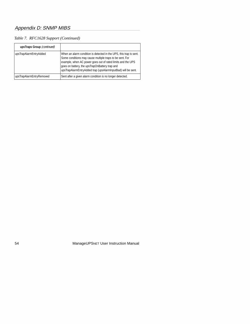
upsTraps Group (continued)
upsTrapAlarmEntryAdded When an alarm condition is detected in the UPS, this trap is sent. Some conditions may cause multiple traps to be sent. For example, when AC power goes out of rated limits and the UPS goes on battery, the upsTrapOnBattery trap and upsTrapAlarmEntryAdded trap (upsAlarmInputBad) will be sent.
upsTrapAlarmEntryRemoved Sent after a given alarm condition is no longer detected.
Table 7. RFC1628 Support (Continued)
Appendix D: SNMP MIBS
ManageUPSNET User Instruction Manual 55
ONEAC Private Extension MIB
This section details information about ONEAC’s Private Extensions UPS MIB. This MIB is also provided in the SNMP Agent and use of it is optional. ONEACXT.MIB is the name of this MIB and it is found in the MIBS directory on the ONEAC SNMP Diskette. NOTE: This information is in addition to the descriptions provided in the MIB.
Table 8. Private Extension MIB
oneacUpsIdent Group
NOTE: The objects in this group are read-only and are provided so that the Network manageability adapter can be fully identified via the network.
oneacUpsSNMPInterfaceModel This object identifies the Model of the Interface. Example: AK-SNMP-NE
oneacUpsSNMPInterfaceDateCode Year/Week date of manufacture codeExample: 9710 (1997, Week 10)
oneacUpsSNMPInterfaceSerialNo Unique serial number of the interface.
oneacUpsAgentBuildDate Date at which the ManageUPSNET Firmware was compiled.
oneacUpsAgentBuildTime Time at which the ManageUPSNET Firmware was compiled.
oneacUpsDateCode The date of manufacture for the UPS in the form of yymmdd.
oneacUpsSerialNo The serial number of the UPS
oneacUpsName A 12 character name UPS name stored on the UPS itself.
oneacUpsControl Group
oneacUpsControlNotifyDelay The number of seconds the UPS waits after detecting a power failure before any notification occurs.
oneacUpsControlOffOn Any positive value written to this object will cause the UPS to be reset in the same manner as if the front panel switch was turned off and then back on. This can be used in situations where a manual restart is required.
oneacUpsControlPwrFailSim Any positive value written to this object will cause the UPS to go on battery power for about 15 seconds.
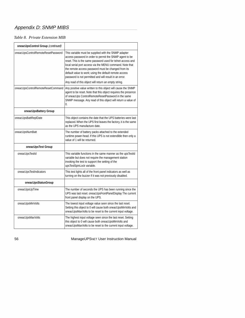
Appendix D: SNMP MIBS
56 ManageUPSNET User Instruction Manual
oneacUpsControl Group (continued)
oneacUpsControlRemoteResetPassword This variable must be supplied with the SNMP adapter access password in order to permit the SNMP agent to be reset. This is the same password used for telnet access and local serial port access via the MENU command. Note that the remote access password must be changed from its default value to work; using the default remote access password is not permitted and will result in an error.
Any read of this object will return an empty string.
oneacUpsControlRemoteResetCommand Any positive value written to this object will cause the SNMP agent to be reset. Note that this object requires the presence of oneacUps ControlRemoteResetPassword in the same SNMP message. Any read of this object will return a value of 0.
oneacUpsBattery Group
oneacUpsBattReplDate This object contains the date that the UPS batteries were last replaced. When the UPS first leaves the factory, it is the same as the UPS manufacture date.
oneacUpsNumBatt The number of battery packs attached to the extended runtime power-head. If this UPS is not extendible then only a value of 1 will be returned.
oneacUpsTest Group
oneacUpsTestId This variable functions in the same manner as the upsTestId variable but does not require the management station invoking the test to support the setting of the upsTestSpinLock variable.
oneacUpsTestIndicators This test lights all of the front panel indicators as well as turning on the buzzer if it was not previously disabled.
oneacUpsStatusGroup
oneacUpsUpTime The number of seconds the UPS has been running since the UPS was last reset. oneacUpsFrontPanelDisplay The current front panel display on the UPS.
oneacUpsMinVolts The lowest input voltage value seen since the last reset. Setting this object to 0 will cause both oneacUpsMinVolts and oneacUpsMaxVolts to be reset to the current input voltage.
oneacUpsMaxVolts The highest input voltage seen since the last reset. Setting this object to 0 will cause both oneacUpsMinVolts and oneacUpsMaxVolts to be reset to the current input voltage.
Table 8. Private Extension MIB
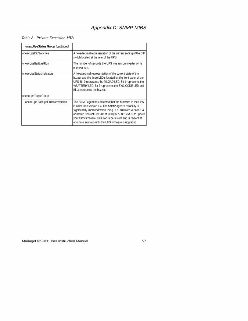
Appendix D: SNMP MIBS
ManageUPSNET User Instruction Manual 57
oneacUpsStatus Group (continued)
oneacUpsDipSwitches A hexadecimal representation of the current setting of the DIP switch located at the rear of the UPS.
oneacUpsBattLastRun The number of seconds the UPS was run on inverter on its previous run.
oneacUpsStatusIndicators A hexadecimal representation of the current state of the buzzer and the three LED’s located on the front panel of the UPS. Bit 0 represents the %LOAD LED, Bit 1 represents the %BATTERY LED, Bit 2 represents the SYS. CODE LED and Bit 3 represents the buzzer.
oneacUpsTraps Group
oneacUpsTrapUpsFirmwareVersion The SNMP agent has detected that the firmware in the UPS is older than version 1.4. The SNMP agent’s reliability is significantly improved when using UPS firmware version 1.4 or newer. Contact ONEAC at (800) 327-8801 ext. 3, to update your UPS firmware. This trap is persistent and is re-sent at one hour intervals until the UPS firmware is upgraded.
Table 8. Private Extension MIB
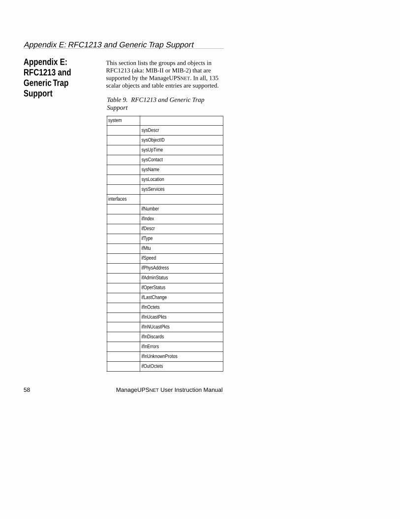
Appendix E: RFC1213 and Generic Trap Support
58 ManageUPSNET User Instruction Manual
Appendix E: RFC1213 and Generic Trap Support
This section lists the groups and objects in RFC1213 (aka: MIB-II or MIB-2) that are supported by the ManageUPSNET. In all, 135 scalar objects and table entries are supported.
Table 9. RFC1213 and Generic Trap Support
system
sysDescr
sysObjectID
sysUpTime
sysContact
sysName
sysLocation
sysServices
interfaces
ifNumber
ifIndex
ifDescr
ifType
ifMtu
ifSpeed
ifPhysAddress
ifAdminStatus
ifOperStatus
ifLastChange
ifInOctets
ifInUcastPkts
ifInNUcastPkts
ifInDiscards
ifInErrors
ifInUnknownProtos
ifOutOctets
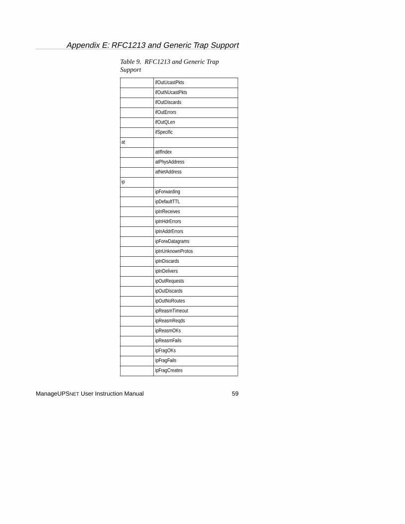
Appendix E: RFC1213 and Generic Trap Support
ManageUPSNET User Instruction Manual 59
ifOutUcastPkts
ifOutNUcastPkts
ifOutDiscards
ifOutErrors
ifOutQLen
ifSpecific
at
atIfIndex
atPhysAddress
atNetAddress
ip
ipForwarding
ipDefaultTTL
ipInReceives
ipInHdrErrors
ipInAddrErrors
ipForwDatagrams
ipInUnknownProtos
ipInDiscards
ipInDelivers
ipOutRequests
ipOutDiscards
ipOutNoRoutes
ipReasmTimeout
ipReasmReqds
ipReasmOKs
ipReasmFails
ipFragOKs
ipFragFails
ipFragCreates
Table 9. RFC1213 and Generic Trap Support
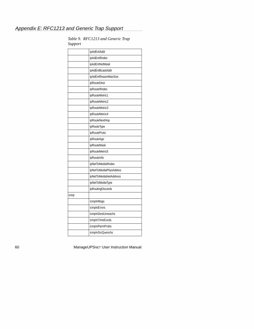
Appendix E: RFC1213 and Generic Trap Support
60 ManageUPSNET User Instruction Manual
ipAdEntAddr
ipAdEntIfIndex
ipAdEntNetMask
ipAdEntBcastAddr
ipAdEntReasmMaxSize
ipRouteDest
ipRouteIfIndex
ipRouteMetric1
ipRouteMetric2
ipRouteMetric3
ipRouteMetric4
ipRouteNextHop
ipRouteType
ipRouteProto
ipRouteAge
ipRouteMask
ipRouteMetric5
ipRouteInfo
ipNetToMediaIfIndex
ipNetToMediaPhysAddres
ipNetToMediaNetAddress
ipNetToMediaType
ipRoutingDiscards
icmp
icmpInMsgs
icmpInErrors
icmpInDestUnreachs
icmpInTimeExcds
icmpInParmProbs
icmpInSrcQuenchs
Table 9. RFC1213 and Generic Trap Support
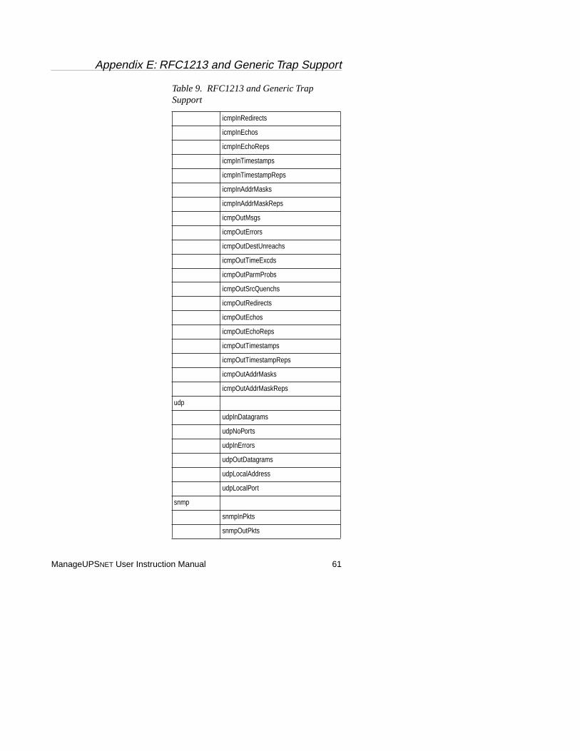
Appendix E: RFC1213 and Generic Trap Support
ManageUPSNET User Instruction Manual 61
icmpInRedirects
icmpInEchos
icmpInEchoReps
icmpInTimestamps
icmpInTimestampReps
icmpInAddrMasks
icmpInAddrMaskReps
icmpOutMsgs
icmpOutErrors
icmpOutDestUnreachs
icmpOutTimeExcds
icmpOutParmProbs
icmpOutSrcQuenchs
icmpOutRedirects
icmpOutEchos
icmpOutEchoReps
icmpOutTimestamps
icmpOutTimestampReps
icmpOutAddrMasks
icmpOutAddrMaskReps
udp
udpInDatagrams
udpNoPorts
udpInErrors
udpOutDatagrams
udpLocalAddress
udpLocalPort
snmp
snmpInPkts
snmpOutPkts
Table 9. RFC1213 and Generic Trap Support
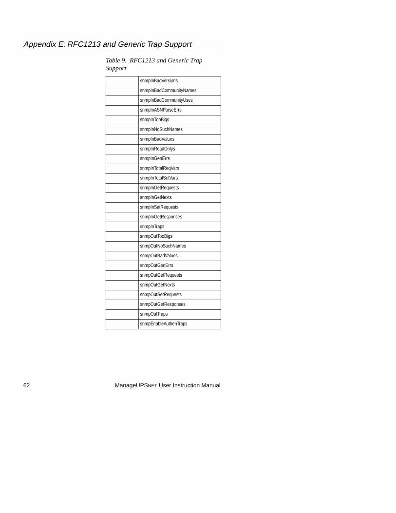
Appendix E: RFC1213 and Generic Trap Support
62 ManageUPSNET User Instruction Manual
snmpInBadVersions
snmpInBadCommunityNames
snmpInBadCommunityUses
snmpInASNParseErrs
snmpInTooBigs
snmpInNoSuchNames
snmpInBadValues
snmpInReadOnlys
snmpInGenErrs
snmpInTotalReqVars
snmpInTotalSetVars
snmpInGetRequests
snmpInGetNexts
snmpInSetRequests
snmpInGetResponses
snmpInTraps
snmpOutTooBigs
snmpOutNoSuchNames
snmpOutBadValues
snmpOutGenErrs
snmpOutGetRequests
snmpOutGetNexts
snmpOutSetRequests
snmpOutGetResponses
snmpOutTraps
snmpEnableAuthenTraps
Table 9. RFC1213 and Generic Trap Support
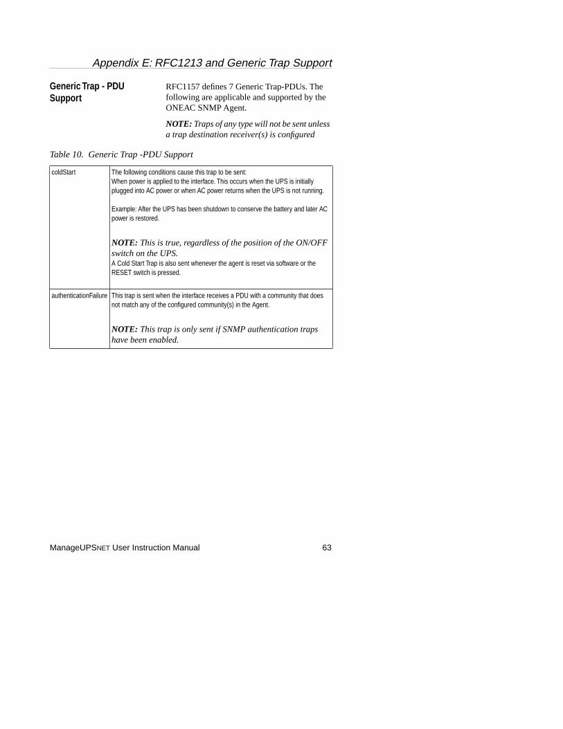
Appendix E: RFC1213 and Generic Trap Support
ManageUPSNET User Instruction Manual 63
Generic Trap - PDU Support
RFC1157 defines 7 Generic Trap-PDUs. The following are applicable and supported by the ONEAC SNMP Agent.
NOTE: Traps of any type will not be sent unless a trap destination receiver(s) is configured
Table 10. Generic Trap -PDU Support
coldStart The following conditions cause this trap to be sent:When power is applied to the interface. This occurs when the UPS is initially plugged into AC power or when AC power returns when the UPS is not running.
Example: After the UPS has been shutdown to conserve the battery and later AC power is restored.
NOTE: This is true, regardless of the position of the ON/OFF switch on the UPS.A Cold Start Trap is also sent whenever the agent is reset via software or the RESET switch is pressed.
authenticationFailure This trap is sent when the interface receives a PDU with a community that does not match any of the configured community(s) in the Agent.
NOTE: This trap is only sent if SNMP authentication traps have been enabled.
Appendix F: Pass-through Mode
64 ManageUPSNET User Instruction Manual
Appendix F: Pass-through Mode
The pass-through mode can be used for Out-Of-Band access or local serial monitoring. Both internal and external versions of the ManageUPSnet adapter allow the re-use of the UPS serial port for other utilities that need to communicate serially with the UPS.
In pass-through mode, ManageUPS suspends its conversation with the UPS and yields the port to the external entity. If there is no activity on the port for 2-4 seconds, ManageUPS takes control of the port for its own use until a new request enters from the external device.
If the external entity monopolizes the port, ManageUPS will interrupt the session every minute to update itself with UPS status information. The interruption lasts less than one second, after which the port is yielded again to the external device.
A common external device may be a terminal or Windows application requesting a private session with the UPS either locally or via modem for configuration adjustment or diagnostics of the UPS.