Embed Size (px)
Citation preview

OL-31018-01
C H A P T E R 28
Managing Mobile NetworksThe following topics provide an overview of mobile technologies and describe how to work with mobile technologies using the Vision client. If you cannot perform an operation that is described in these topics, you may not have sufficient permissions; see .
• GPRS/UMTS Networks, page 28-1
• LTE Networks, page 28-49
• Scheduling 3GPP Inventory Retrieval Requests, page 28-117
• Viewing Operator Policies, APN Remaps, and APN Profiles, page 28-119
• Working with Active Charging Service, page 28-129
• Mobile Technologies Commands: Summary, page 28-146
GPRS/UMTS NetworksThese topics describe how to use Prime Network to manage GPRS/UMTS networks:
• Overview of GPRS/UMTS Networks, page 28-1
• Working With GPRS/UMTS Network Technologies, page 28-3
Overview of GPRS/UMTS NetworksGeneral Packet Radio Service (GPRS) and Universal Mobile Telecommunication System (UMTS) are evolutions of Global System for Mobile Communication (GSM) networks.
GPRS is a 2.5G mobile communications technology that enables mobile wireless service providers to offer their mobile subscribers packet-based data services over GSM networks. UMTS is a 3G mobile communications technology that provides wideband code division multiple access (CDMA) radio technology. Figure 28-1 shows a basic GPRS/UMTS network topology.
28-1Cisco Prime Network 4.1 User Guide

Chapter 28 Managing Mobile Networks GPRS/UMTS Networks
Figure 28-1 Basic GPRS/UMTS Network Topology
The GPRS/UMTS packet core comprises two major network elements:
• Gateway GPRS support node (GGSN)—A gateway that provides mobile cell phone users access to a Packet Data Network (PDN) or specified private Internet Protocol (IP) networks.
• Serving GPRS support node (SGSN)—Connects the radio access network (RAN) to the GPRS/UMTS core and tunnels user sessions to the GGSN. The SGSN sends data to and receives data from mobile stations, and maintains information about the location of a mobile station (MS). The SGSN communicates directly with the MS and the GGSN.
PDNs are associated with Access Point Names (APNs) configured on the system. Each APN consists of a set of parameters that dictate how subscriber authentication and IP address assignment is to be handled for that APN.
The Vision client allows you to configure the mobile technologies by using commands and also view the properties configured for the mobile technologies. Figure 28-2 shows an example of the Inventory window with the mobile technology nodes/containers under the Mobile context.
To see which devices support mobile technologies, refer to Cisco Prime Network 4.1 Supported VNEs.
28-2Cisco Prime Network 4.1 User Guide
OL-31018-01

Chapter 28 Managing Mobile Networks GPRS/UMTS Networks
Figure 28-2 Mobile Technology Nodes in Logical Inventory
Working With GPRS/UMTS Network TechnologiesThe following topics explain how to work with GPRS/UMTS network technologies in the Vision client:
• Working with the Gateway GPRS Support Node(GGSN), page 28-3
• Working with the GPRS Tunneling Protocol User Plane (GTPU), page 28-8
• Working with Access Point Names (APNs), page 28-9
• Working with GPRS Tunneling Protocol Prime (GTPP), page 28-20
• Working with the Evolved GPS Tunneling Protocol (eGTP), page 28-26
• Monitoring the Serving GPRS Support Node (SGSN), page 28-27
Working with the Gateway GPRS Support Node(GGSN)
The GGSN works in conjunction with SGSNs within the network to perform the following functions:
• Establish and maintain subscriber Internet Protocol (IP) or Point-to-Point Protocol (PPP) type Packet Data Protocol (PDP) contexts originated by either the mobile or the network.
• Provide charging detail records (CDRs) to the charging gateway ((CG), also known as the Charging Gateway Function (CGF)).
• Route data traffic between the subscriber’s Mobile Station (MS) and a PDN such as the Internet or an intranet.
28-3Cisco Prime Network 4.1 User Guide
OL-31018-01

Chapter 28 Managing Mobile Networks GPRS/UMTS Networks
In addition, to providing basic GGSN functionality as described above, the system can be configured to support Mobile IP and/or Proxy Mobile IP data applications in order to provide mobility for subscriber IP PDP contexts. When supporting these services, the system can be configured to function as a GGSN and Foreign Agent (FA), a stand-alone Home Agent (HA), or a GGSN, FA, and HA simultaneously within the carrier's network.
The following topics explain how to work with GGSN in the Vision client:
• Viewing GGSN Properties, page 28-4
• Viewing Additional Characteristics of a GGSN, page 28-5
• GGSN Commands, page 28-7
Viewing GGSN Properties
The Vision client displays the GGSNs in a GGSN container under the Mobile node in the logical inventory. The icon used for representing GGSNs in the logical inventory is explained in NE Logical Inventory Icons, page 1-7.
To view GGSN properties:
Step 1 Right-click the required device in the Vision client and choose Inventory.
Step 2 In the logical inventory window, choose Logical Inventory > Context > Mobile > GGSN Container.
The Vision client displays the list of GGSNs configured under the container. You can view the individual GGSN details from the table on the right pane or by choosing Logical Inventory > Context > Mobile > GGSN Container > GGSN.
Table 28-1 describes the details available for each GGSN.
Table 28-1 GGSN Properties in Logical Inventory
Field Description
Service Name The name of the GGSN service.
Status The status of the GGSN service. Value could be Unknown, Running, or Down.
PLMN Policy The PLMN policy for handling communications from SGSNs that are not configured to communicate with.
Newcall Policy Specifies whether to accept or reject a new incoming call.
Authentication Server Timeout
The code used by the GGSN as a response message if communication with an authentication server times out. Value could be System Failure or User Authentication Failed.
Accounting Server Timeout
The code used by the GGSN as a response message if communication with an accounting server times out. Value could be System Failure or No Resouces.
GTPU The GTPU that is associated with the GGSN and manages the GTP messages between GGSN and a radio access network equipment (RNC).
Accounting Context The context that processes accounting for PDP contexts handled by the GGSN service.
Local IP Address The local IP address bounded with the GGSN service.
28-4Cisco Prime Network 4.1 User Guide
OL-31018-01
Chapter 28 Managing Mobile Networks GPRS/UMTS Networks
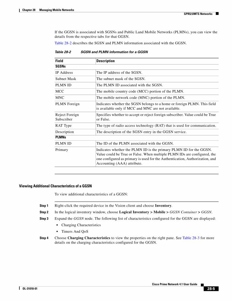
If the GGSN is associated with SGSNs and Public Land Mobile Networks (PLMNs), you can view the details from the respective tabs for that GGSN.
Table 28-2 describes the SGSN and PLMN information associated with the GGSN.
Viewing Additional Characteristics of a GGSN
To view additional characteristics of a GGSN:
Step 1 Right-click the required device in the Vision client and choose Inventory.
Step 2 In the logical inventory window, choose Logical Inventory > Mobile > GGSN Container > GGSN.
Step 3 Expand the GGSN node. The following list of characteristics configured for the GGSN are displayed:
• Charging Characteristics
• Timers And QoS
Step 4 Choose Charging Characteristics to view the properties on the right pane. See Table 28-3 for more details on the charging characteristics configured for the GGSN.
Table 28-2 SGSN and PLMN information for a GGSN
Field DescriptionSGSNs
IP Address The IP address of the SGSN.
Subnet Mask The subnet mask of the SGSN.
PLMN ID The PLMN ID associated with the SGSN.
MCC The mobile country code (MCC) portion of the PLMN.
MNC The mobile network code (MNC) portion of the PLMN.
PLMN Foreign Indicates whether the SGSN belongs to a home or foreign PLMN. This field is available only if MCC and MNC are not available.
Reject Foreign Subscriber
Specifies whether to accept or reject foreign subscriber. Value could be True or False.
RAT Type The type of radio access technology (RAT) that is used for communication.
Description The description of the SGSN entry in the GGSN service.
PLMNs
PLMN ID The ID of the PLMN associated with the GGSN.
Primary Indicates whether the PLMN ID is the primary PLMN ID for the GGSN. Value could be True or False. When multiple PLMN IDs are configured, the one configured as primary is used for the Authentication, Authorization, and Accounting (AAA) attribute.
28-5Cisco Prime Network 4.1 User Guide
OL-31018-01
Chapter 28 Managing Mobile Networks GPRS/UMTS Networks
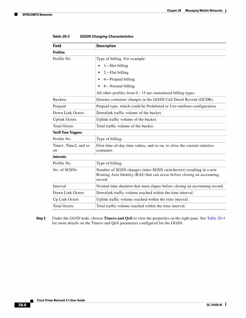
Step 5 Under the GGSN node, choose Timers and QoS to view the properties on the right pane. See Table 28-4 for more details on the Timers and QoS parameters configured for the GGSN.
Table 28-3 GGSN Charging Characteristics
Field Description
Profiles
Profile No Type of billing. For example:
• 1—Hot billing
• 2—Flat billing
• 4—Prepaid billing
• 8—Normal billing
All other profiles from 0 - 15 are customized billing types.
Buckets Denotes container changes in the GGSN Call Detail Record (GCDR).
Prepaid Prepaid type, which could be Prohibited or Use-rulebase-configuration.
Down Link Octets Downlink traffic volume of the bucket.
Uplink Octets Uplink traffic volume of the bucket.
Total Octets Total traffic volume of the bucket.
Tariff Time Triggers
Profile No Type of billing.
Time1, Time2, and so on
First time-of-day time values, and so on, to close the current statistics container.
Intervals
Profile No Type of billing.
No. of SGSNs Number of SGSN changes (inter-SGSN switchovers) resulting in a new Routing Area Identity (RAI) that can occur before closing an accounting record.
Interval Normal time duration that must elapse before closing an accounting record.
Down Link Octets Downlink traffic volume reached within the time interval.
Up Link Octets Uplink traffic volume reached within the time interval.
Total Octets Total traffic volume reached within the time interval.
28-6Cisco Prime Network 4.1 User Guide
OL-31018-01

Chapter 28 Managing Mobile Networks GPRS/UMTS Networks
GGSN Commands
The following GGSN-related commands can be launched from the inventory by right-clicking a GGSN and choosing GGSN > Commands > Configuration. Your permissions determine whether you can run these commands (see ). To find out if a device supports these commands, see the Cisco Prime Network 4.0 Supported Cisco VNEs.
Table 28-4 GGSN Timers and QoS
Field Description
Retransmission Timeout
Timeout, in seconds, for retransmission of GTP control packets.
Max Retransmissions Maximum retries for transmitting GTP control packets.
Setup Timeout Maximum time, in seconds, allowed for session setup.
Echo Interval Echo interval, in seconds, for GTP.
Guard Interval Interval, in seconds, for which the GGSN maintains responses sent to SGSN. This optimizes the handling of retransmitted messages.
QCI to DSCP Mapping
QoS class index A set of transport characteristics used to differentiate various packet flows.
DSCP Differentiated Services Code Point (DSCP), a mechanism for classifying and managing network traffic and providing QoS.
QCI & ARP DSCP Mapping
QoS class index A set of transport characteristics used to differentiate various packet flows.
Allocation retention priority
The priority of allocation and retention of the service data flow. This parameter allows prioritizing allocation of resources during bearer establishment and modification. During network traffic congestions, a lower ARP flow is dropped to free up the capacity.
DSCP A mechanism for classifying and managing network traffic and providing QoS.
Table 28-5 GGSN Commands
Command Navigation Description
Create PLMN Identifier Right-click on a GGSN group > Commands > Configuration
Use this command to create a PLMN Identifier.
Create SGSN Use this command to create an SGSN.
Delete GGSN Use this command to delete a GGSN profile.
Modify GGSN Use this command to modify a GGSN profile details.
28-7Cisco Prime Network 4.1 User Guide
OL-31018-01
Chapter 28 Managing Mobile Networks GPRS/UMTS Networks
Working with the GPRS Tunneling Protocol User Plane (GTPU)
The GGSN communicates with SGSNs on a Public Land Mobile Network (PLMN) using the GPRS Tunneling Protocol (GTP). The signaling or control aspect of this protocol is referred to as the GTP Control Plane (GTPC) while the encapsulated user data traffic is referred to as the GTP User Plane (GTPU). GTPU is used for transferring user data in separated tunnels for each PDP context.
You can configure various parameters for a GTPU using the configuration commands in the Vision client. You can view the configured parameters for a GTPU in the logical inventory.
The following topics explain how to work with GTPU in the Vision client:
• Viewing GTPU Properties, page 28-8
• GTPU Commands, page 28-9
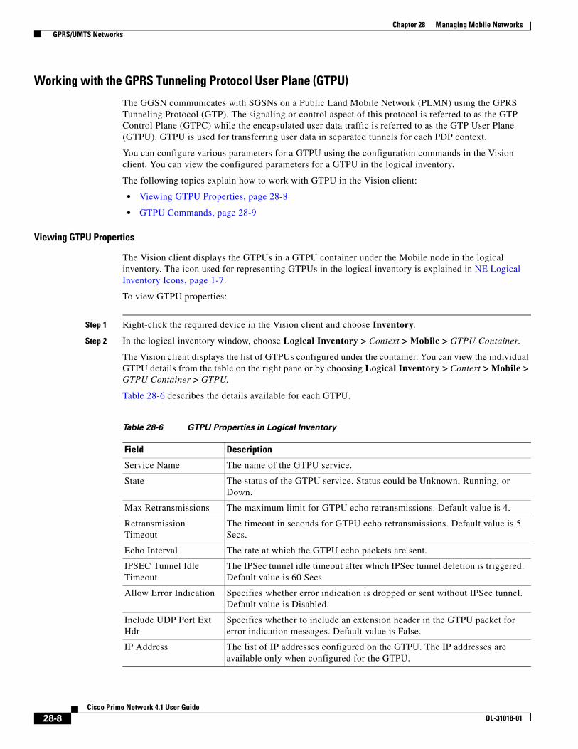
Viewing GTPU Properties
The Vision client displays the GTPUs in a GTPU container under the Mobile node in the logical inventory. The icon used for representing GTPUs in the logical inventory is explained in NE Logical Inventory Icons, page 1-7.
To view GTPU properties:
Step 1 Right-click the required device in the Vision client and choose Inventory.
Step 2 In the logical inventory window, choose Logical Inventory > Context > Mobile > GTPU Container.
The Vision client displays the list of GTPUs configured under the container. You can view the individual GTPU details from the table on the right pane or by choosing Logical Inventory > Context > Mobile > GTPU Container > GTPU.
Table 28-6 describes the details available for each GTPU.
Table 28-6 GTPU Properties in Logical Inventory
Field Description
Service Name The name of the GTPU service.
State The status of the GTPU service. Status could be Unknown, Running, or Down.
Max Retransmissions The maximum limit for GTPU echo retransmissions. Default value is 4.
Retransmission Timeout
The timeout in seconds for GTPU echo retransmissions. Default value is 5 Secs.
Echo Interval The rate at which the GTPU echo packets are sent.
IPSEC Tunnel Idle Timeout
The IPSec tunnel idle timeout after which IPSec tunnel deletion is triggered. Default value is 60 Secs.
Allow Error Indication Specifies whether error indication is dropped or sent without IPSec tunnel. Default value is Disabled.
Include UDP Port Ext Hdr
Specifies whether to include an extension header in the GTPU packet for error indication messages. Default value is False.
IP Address The list of IP addresses configured on the GTPU. The IP addresses are available only when configured for the GTPU.
28-8Cisco Prime Network 4.1 User Guide
OL-31018-01
Chapter 28 Managing Mobile Networks GPRS/UMTS Networks
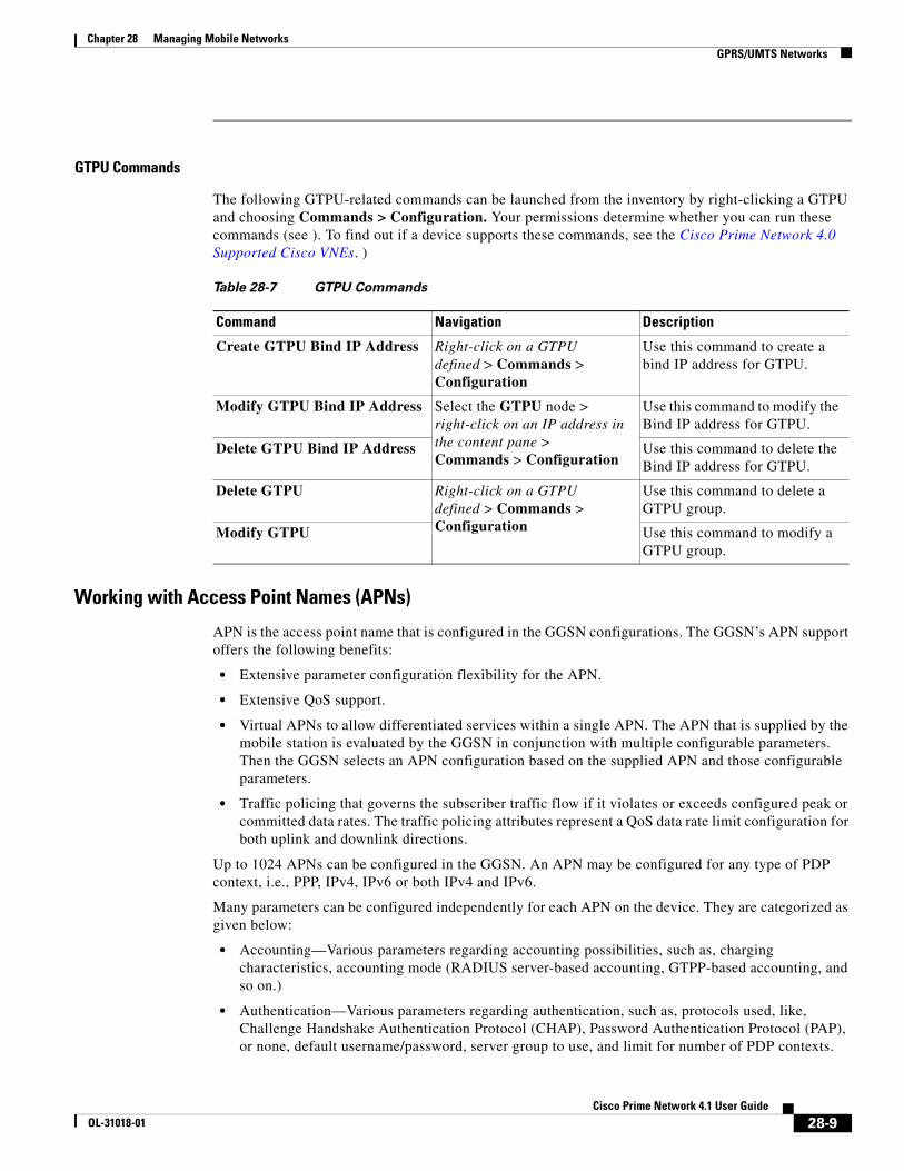
GTPU Commands
The following GTPU-related commands can be launched from the inventory by right-clicking a GTPU and choosing Commands > Configuration. Your permissions determine whether you can run these commands (see ). To find out if a device supports these commands, see the Cisco Prime Network 4.0 Supported Cisco VNEs. )
Working with Access Point Names (APNs)
APN is the access point name that is configured in the GGSN configurations. The GGSN’s APN support offers the following benefits:
• Extensive parameter configuration flexibility for the APN.
• Extensive QoS support.
• Virtual APNs to allow differentiated services within a single APN. The APN that is supplied by the mobile station is evaluated by the GGSN in conjunction with multiple configurable parameters. Then the GGSN selects an APN configuration based on the supplied APN and those configurable parameters.
• Traffic policing that governs the subscriber traffic flow if it violates or exceeds configured peak or committed data rates. The traffic policing attributes represent a QoS data rate limit configuration for both uplink and downlink directions.
Up to 1024 APNs can be configured in the GGSN. An APN may be configured for any type of PDP context, i.e., PPP, IPv4, IPv6 or both IPv4 and IPv6.
Many parameters can be configured independently for each APN on the device. They are categorized as given below:
• Accounting—Various parameters regarding accounting possibilities, such as, charging characteristics, accounting mode (RADIUS server-based accounting, GTPP-based accounting, and so on.)
• Authentication—Various parameters regarding authentication, such as, protocols used, like, Challenge Handshake Authentication Protocol (CHAP), Password Authentication Protocol (PAP), or none, default username/password, server group to use, and limit for number of PDP contexts.
Table 28-7 GTPU Commands
Command Navigation Description
Create GTPU Bind IP Address Right-click on a GTPU defined > Commands > Configuration
Use this command to create a bind IP address for GTPU.
Modify GTPU Bind IP Address Select the GTPU node > right-click on an IP address in the content pane > Commands > Configuration
Use this command to modify the Bind IP address for GTPU.
Delete GTPU Bind IP Address Use this command to delete the Bind IP address for GTPU.
Delete GTPU Right-click on a GTPU defined > Commands > Configuration
Use this command to delete a GTPU group.
Modify GTPU Use this command to modify a GTPU group.
28-9Cisco Prime Network 4.1 User Guide
OL-31018-01

Chapter 28 Managing Mobile Networks GPRS/UMTS Networks
• Enhanced Charging—Name of rulebase to use, which holds the enhanced charging configuration (for example, eG-CDR variations, charging rules, prepaid/postpaid options, etc.).
• IP: Method for IP address allocation (e.g., local allocation by GGSN, Mobile IP, Dynamic Host Control Protocol (DHCP), DHCP relay, etc.). IP address ranges, with or without overlapping ranges across APNs.
• Tunneling: PPP may be tunneled with L2TP. IPv4 may be tunneled with GRE, IP-in-IP or L2TP. Load-balancing across multiple tunnels. IPv6 is tunneled in IPv4. Additional tunneling techniques, such as, IPsec and VLAN tagging may be selected by the APN, but are configured in the GGSN independently from the APN.
• QoS: IPv4 header ToS handling. Traffic rate limits for different 3GPP traffic classes. Mapping of R98 QoS attributes to work around particular handset defections. Dynamic QoS renegotiation (described elsewhere).
You can configure the APN parameters using the Vision client. You can view the configured parameters for an APN in the logical inventory. After an APN is determined by the GGSN, the subscriber may be authenticated/authorized with an AAA server. The GGSN allows the AAA server to return Vendor Specific Attributes (VSAs) that override any or all of the APN configuration. This allows different subscriber tier profiles to be configured in the AAA server, and passed to the GGSN during subscriber authentication/authorization.
The following topics explain how to work with APN in the Vision client:
• Viewing APN Properties, page 28-10
• Viewing Additional Characteristics of an APN, page 28-14
• APN Commands, page 28-19
Viewing APN Properties
The Vision client displays the APNs in an APN container under the Mobile node in the logical inventory. You can also view additional characteristics configured on the APN as explained in Viewing Additional Characteristics of an APN, page 28-14. The icon used for representing APNs in the logical inventory is explained in NE Logical Inventory Icons, page 1-7.
To view APN properties:
Step 1 Right-click the required device in the Vision client and choose Inventory.
Step 2 In the logical inventory window, choose Logical Inventory > Context > Mobile > APN Container > APN.
Table 28-8 describes the information that is available for the APN. The information that is displayed depends on the configuration of the APN.
Table 28-8 APN Properties in Logical Inventory
Field Description
APN Name The APN name.
Accounting Mode The accounting protocol in use in the APN. Values are GTPP (GPRS Tunneling Protocol Prime), RADIUS (Remote Authentication Dial In User Service), or None.
Selection Mode The selection mode in use in the APN. Selection mode indicates the origin of the requested APN and whether or not the Home Location Register (HLR) has verified the user subscription.
28-10Cisco Prime Network 4.1 User Guide
OL-31018-01
Chapter 28 Managing Mobile Networks GPRS/UMTS Networks
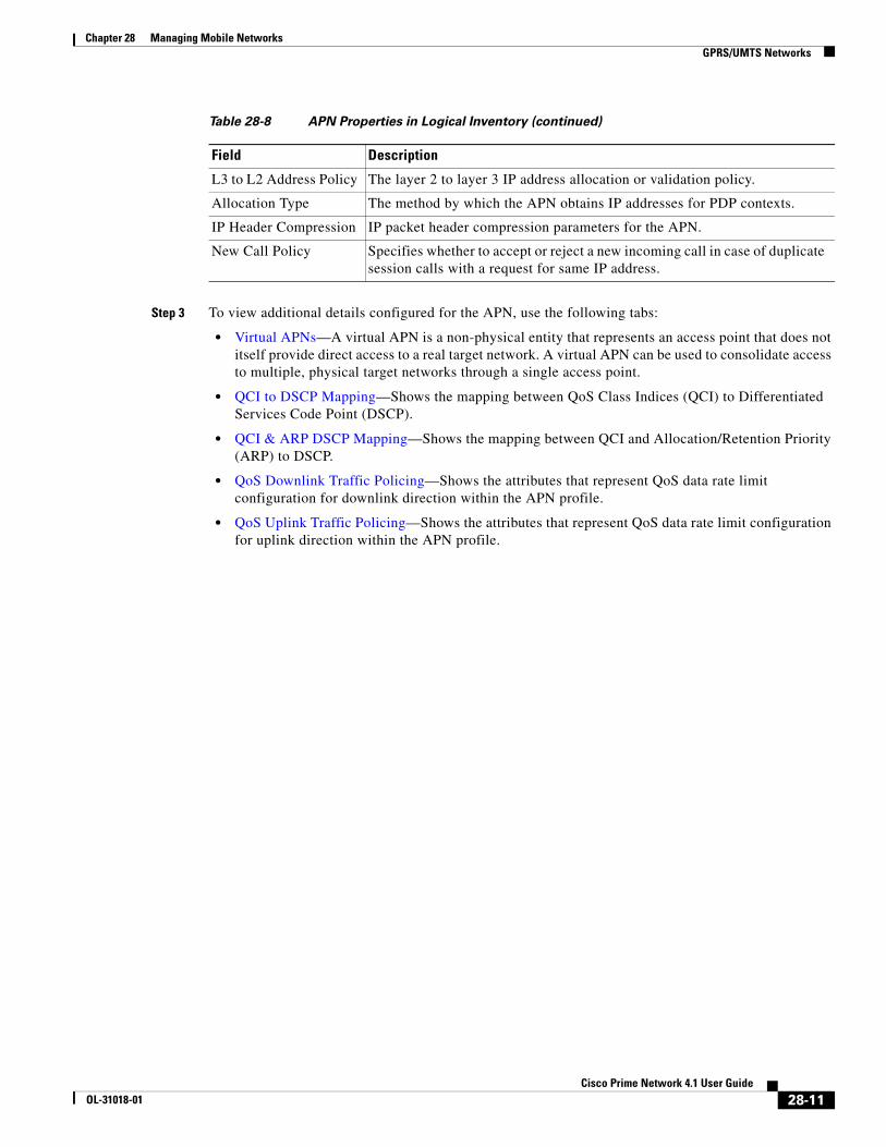
Step 3 To view additional details configured for the APN, use the following tabs:
• Virtual APNs—A virtual APN is a non-physical entity that represents an access point that does not itself provide direct access to a real target network. A virtual APN can be used to consolidate access to multiple, physical target networks through a single access point.
• QCI to DSCP Mapping—Shows the mapping between QoS Class Indices (QCI) to Differentiated Services Code Point (DSCP).
• QCI & ARP DSCP Mapping—Shows the mapping between QCI and Allocation/Retention Priority (ARP) to DSCP.
• QoS Downlink Traffic Policing—Shows the attributes that represent QoS data rate limit configuration for downlink direction within the APN profile.
• QoS Uplink Traffic Policing—Shows the attributes that represent QoS data rate limit configuration for uplink direction within the APN profile.
L3 to L2 Address Policy The layer 2 to layer 3 IP address allocation or validation policy.
Allocation Type The method by which the APN obtains IP addresses for PDP contexts.
IP Header Compression IP packet header compression parameters for the APN.
New Call Policy Specifies whether to accept or reject a new incoming call in case of duplicate session calls with a request for same IP address.
Table 28-8 APN Properties in Logical Inventory (continued)
Field Description
28-11Cisco Prime Network 4.1 User Guide
OL-31018-01

Chapter 28 Managing Mobile Networks GPRS/UMTS Networks
Table 28-9 Additional Configuration Details for APN
Field DescriptionVirtual APNs
Preference Specifies the order in which the referenced APNs are compared by the system. Can be configured to any integer value from 1 (highest priority) to 1000 (lowest priority).
APN Specifies the name of an alternative APN configured on the system that is to be used for PDP contexts with matching properties. Value can be from 1 to 62, alpha and/or numeric characters, and is not case-sensitive. It may also contain dots ( . ) and/or dashes (- ).
Rule Definition The virtual APN rule definition can be one of the following:
• access-gw-address—Specifies the access gateway (SGSN/SGW/Others) address for the virtual APN. The IP address can be an IPv4 or IPv6 address in decimal notation. IPv6 also supports :: notation for the IP address.
• bearer-access-service—Specifies the bearer access service name for the virtual APN.
• service name—Specifies the service name. Service name is unique across all the contexts. Value is a string of size 1 to 63.
• cc-profile—Specifies the APN for charging characteristics (CC) profile index. Value is an integer from 1 to 15.
• Domain name—Specifies the subscriber’s domain name (realm). Domain name can be from 1 to 79 alpha and/or numeric characters.
• MCC—Specifies the MCC portion of the PLMN identifier. Value is an integer between 100 to 999.
• MNC—Specifies the MNC portion of the PLMN identifier. Value is an integer between 100 to 999.
• msisdn-range—Specifies the APN for this MSISDN range. The starting and ending values of the range is a string of size 2 to 15 with values between 00 and 999999999999999.
• Rat-Type—Specifies the rat-type option, which could be gan, geran, hspa, utran, or wlan.
• Roaming mode—Specifies the roaming mode, which could be Home, Visiting, or Roaming.
QCI to DSCP Mapping
QoS class index Denotes a set of transport characteristics used to differentiate various packet flows.
DSCP Denotes a mechanism for classifying and managing network traffic and providing QoS.
QCI & ARP DSCP Mapping
QoS class index Denotes a set of transport characteristics used to differentiate various packet flows.
28-12Cisco Prime Network 4.1 User Guide
OL-31018-01

Chapter 28 Managing Mobile Networks GPRS/UMTS Networks
Allocation retention priority
Indicates the priority of allocation and retention of the service data flow. This parameter allows prioritizing allocation of resources during bearer establishment and modification. During network traffic congestions, a lower ARP flow is dropped to free up the capacity.
DSCP Denotes a mechanism for classifying and managing network traffic and providing QoS.
QoS Downlink Traffic Policing
QCI A scalar that denotes a set of transport characteristics and used to infer nodes specific parameters that control packet forwarding treatment.
Peak Data Rate The peak data rate allowed, in bytes, for the downlink direction and QoS traffic class.
Committed Data Rate The committed data rate allowed, in bytes, for the downlink direction and QoS traffic class.
Negotiate Limit Indicates whether negotiation limit is enabled or disabled for the downlink direction and Qos traffic class.
Rate Limit Indicates whether the rate limit is enabled or disabled for the downlink direction and Qos traffic class.
Burst Size Auto Readjust
Indicates whether the auto readjustment of burst size is enabled or disabled. This parameter is used in dynamic burst size calculation, for traffic policing, at the time of PDP activation of modification.
Burst Size Auto Readjust Duration
The burst size readjustment duration in seconds. This parameter indicates the number of seconds that the dynamic burst size calculation will last for. This allows the traffic to be throttled at the negotiated rates.
Peak Burst Size (bytes) The peak burst size allowed, in bytes, for the downlink direction and QoS class.
Guaranteed Burst Size (bytes)
The guaranteed burst size allowed, in bytes, for the downlink direction and QoS class.
Exceed Action The action to be taken on packets that exceed the committed data rate, but do not violate the peak data rate. The action could be one of the following:
• Drop
• Lower IP Precedence
• Transmit
Violate Action The action to be taken on packets that exceed both committed and peak data rates. The action could be one of the following:
• Drop
• Lower IP Precedence
• Shape
• Transmit
QoS Uplink Traffic Policing
QCI A scalar that denotes a set of transport characteristics and used to infer nodes specific parameters that control packet forwarding treatment.
Table 28-9 Additional Configuration Details for APN (continued)
Field Description
28-13Cisco Prime Network 4.1 User Guide
OL-31018-01

Chapter 28 Managing Mobile Networks GPRS/UMTS Networks
Viewing Additional Characteristics of an APN
To view additional characteristics of an APN:
Step 1 Right-click the required device in the Vision client and choose Inventory.
Step 2 In the logical inventory window, choose Logical Inventory > Context > Mobile > APN Container > APN.
Peak Data Rate The peak data rate allowed, in bytes, for the uplink direction and QoS traffic class.
Committed Data Rate The committed data rate allowed, in bytes, for the uplink direction and QoS traffic class.
Negotiate Limit Indicates whether negotiation limit is enabled or disabled for the uplink direction and Qos traffic class.
Rate Limit Indicates whether the rate limit is enabled or disabled for the uplink direction and Qos traffic class.
Burst Size Auto Readjust
Indicates whether the auto readjustment of burst size is enabled or disabled. This parameter is used in dynamic burst size calculation, for traffic policing, at the time PDP.
Burst Size Auto Readjust Duration
The burst size readjustment duration in seconds. This parameter indicates the number of seconds that the dynamic burst size calculation will last for. This allows the traffic to be throttled at the negotiated rates.
Peak Burst Size (bytes) The peak burst size allowed, in bytes, for the uplink direction and QoS class.
Guaranteed Burst Size (bytes)
The guaranteed burst size allowed, in bytes, for the uplink direction and QoS class.
Exceed Action The action to be taken on packets that exceed the committed data rate, but do not violate the peak data rate. The action could be one of the following:
• Drop
• Lower IP Precedence
• Transmit
Violate Action The action to be taken on packets that exceed both committed and peak data rates. The action could be one of the following:
• Drop
• Lower IP Precedence
• Shape
• Transmit
Table 28-9 Additional Configuration Details for APN (continued)
Field Description
28-14Cisco Prime Network 4.1 User Guide
OL-31018-01

Chapter 28 Managing Mobile Networks GPRS/UMTS Networks
Step 3 Expand the APN node. The following list of characteristics configured for the APN are displayed:
• Charging Characteristics—Charging characteristics configured on the APN for different subscribers.
• DHCP—Dynamic Host Control Protocol (DHCP) parameter configured, if the APN supports dynamic address assignment for PDP contexts.
• GSM-QoS—Represents the negotiated QoS attribute reliability class based on the configuration provided for service data unit (SDU) error ratio and residual bit error rate (BER) attributes in the APN.
• IP Parameters—Represents the APN parameters related to IP.
• IPv6—Represents IPv6 configurations and related services for the APN.
• Mediation Device—Represents the mediation device used by the APN for communication with the subscriber.
• Mobile IP—Represents mobile IP configuration of the APN.
• Net BIOS—Represents the NetBIOS server configuration used by the APN.
• PDP Contexts Parameters—Represents the PDP contexts supported by the APN.
• PPP Profile—Represents the PPP profile used by the APN.
• RADIUS—Represents the APN parameters related to communication with the RADIUS server.
• Timeout—Represents the timeout parameters of the APN.
• Tunnel Parameters—Represents the parameters configured for tunneling between the GGSN and an external gateway for the APN.
• DNS Configuration—Represents the Domain Name System (DNS) settings configured on the APN.
Step 4 Click each of one of these characteristics to view its properties on the right pane. See Table 28-10 for more details on the properties of each characteristics configured for the APN.
28-15Cisco Prime Network 4.1 User Guide
OL-31018-01

Chapter 28 Managing Mobile Networks GPRS/UMTS Networks
Table 28-10 APN Characteristics
Field DescriptionCharging Characteristics
Home Bit Behavior The behavior bit for charging a home subscriber.
Home Profile The profile index for a home subscriber.
Roaming Bit Behavior The behavior bit for charging a roaming subscriber.
Roaming Profile The profile index for a roaming subscriber.
Visiting Bit Behavior The behavior bit for charging a visiting subscriber.
Visiting Profile The profile index for a visiting subscriber.
All Bit Behavior The behavior bit for charging all subscribers. This value is used only if all subscribers are configured to use the same charging characteristics. This value is overridden by the behavior bit set for a subscriber type.
All Profile The profile index for all subscribers.
Use GGSN The type of the subscriber using the charging characteristics configured on the APN. Value could be Home, Roaming, Visitor, or None. None indicates that the subscriber is using the charging characteristics from the SGSN.
Use RADIUS Returned Specifies whether the GGSN accepts charging characteristics returned from the RADIUS server for all subscribers for the APN. Value could be True or False.
DHCP
Lease Expiration Policy The action taken when leases for IP addresses assigned to PDP contexts that are facilitated by the APN, are about to expire. For example, auto renew.
GSM-QoS
SDU Error Ratio Code The SDU error ratio code based on which the negotiation of QoS attribute reliability class needs to be configured on the APN. Value is an integer between the range 1 and 7. Each code has an assigned value.
Residual BER Code The residual bit error rate (BER) based on which the negotiation of QoS attribute reliability class needs to be configured on the APN. This value is specified if the SDU error ratio code is 1, 2, 3, or 7.
Residual BER code is an integer in the range 1 and 9. Each code has an assigned value.
IP Parameters
In Access Group The name of the IPv4/IPv6 access group for the APN when configured for inbound traffic.
Out Access Group The name of the IPv4/IPv6 access group for the APN when configured for outbound traffic.
Local Address The static local IP address assigned to the APN.
Next Hop Gateway Address
The IP address of the next hop gateway for the APN. This parameter is available only if it is configured on the APN.
Is Discard Enabled Specifies whether multicast discard is enabled or disabled. Value could be True or False.
28-16Cisco Prime Network 4.1 User Guide
OL-31018-01
Chapter 28 Managing Mobile Networks GPRS/UMTS Networks
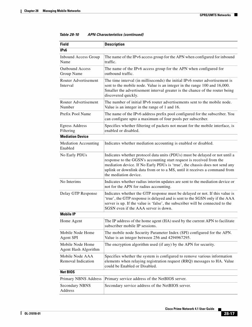
IPv6
Inbound Access Group Name
The name of the IPv6 access group for the APN when configured for inbound traffic.
Outbound Access Group Name
The name of the IPv6 access group for the APN when configured for outbound traffic.
Router Advertisement Interval
The time interval (in milliseconds) the initial IPv6 router advertisement is sent to the mobile node. Value is an integer in the range 100 and 16,000. Smaller the advertisement interval greater is the chance of the router being discovered quickly.
Router Advertisement Number
The number of initial IPv6 router advertisements sent to the mobile node. Value is an integer in the range of 1 and 16.
Prefix Pool Name The name of the IPv6 address prefix pool configured for the subscriber. You can configure upto a maximum of four pools per subscriber.
Egress Address Filtering
Specifies whether filtering of packets not meant for the mobile interface, is enabled or disabled.
Mediation Device
Mediation Accounting Enabled
Indicates whether mediation accounting is enabled or disabled.
No Early PDUs Indicates whether protocol data units (PDUs) must be delayed or not until a response to the GGSN's accounting start request is received from the mediation device. If No Early PDUs is ‘true’, the chassis does not send any uplink or downlink data from or to a MS, until it receives a command from the mediation device.
No Interims Indicates whether radius interim updates are sent to the mediation device or not for the APN for radius accounting.
Delay GTP Response Indicates whether the GTP response must be delayed or not. If this value is ‘true’, the GTP response is delayed and is sent to the SGSN only if the AAA server is up. If the value is ‘false’, the subscriber will be connected to the SGSN even if the AAA server is down.
Mobile IP
Home Agent The IP address of the home agent (HA) used by the current APN to facilitate subscriber mobile IP sessions.
Mobile Node Home Agent SPI
The mobile node Security Parameter Index (SPI) configured for the APN. Value is an integer between 256 and 4294967295.
Mobile Node Home Agent Hash Algorithm
The encryption algorithm used (if any) by the APN for security.
Mobile Node AAA Removal Indication
Specifies whether the system is configured to remove various information elements when relaying registration request (RRQ) messages to HA. Value could be Enabled or Disabled.
Net BIOS
Primary NBNS Address Primary service address of the NetBIOS server.
Secondary NBNS Address
Secondary service address of the NetBIOS server.
Table 28-10 APN Characteristics (continued)
Field Description
28-17Cisco Prime Network 4.1 User Guide
OL-31018-01

Chapter 28 Managing Mobile Networks GPRS/UMTS Networks
PDP Contexts Parameters
Total Contexts The total number of primary and secondary PDP contexts that can be supported by the APN. Value is an integer between 1 and 4,000,000.
PDP Type The type of the PDP contexts supported by the APN.
Primary Contexts The status of the primary contexts of the APN.
PPP Profile
Data Compression Protocols
The compression protocol used by the APN for compression of data packets.
Keep Alive The frequency (in seconds) of sending the Link Control Protocol (LCP) keep alive messages. A value zero denotes that the keep alive messages are disabled completely.
Data Compression Mode
The compression mode used by the compression protocol which could be:
• Normal—Packets are compressed using the packet history.
• Stateless—Each packet is compressed individually.
MTU (bytes) The maximum transmission unit (MTU) for packets accessing the APN.
Min. Compression Size (bytes)
The smallest packet to which compression may be applied.
RADIUS
RADIUS Group The Authentication, Authorization, and Accounting (AAA) group name for the subscriber. If no group is set, the value is displayed as Default.
RADIUS Secondary Group
The secondary AAA group for the APN. If no group is set, the value is displayed as None.
Returned Framed IP Address Policy
The policy which indicates whether to accept or reject a call when the RADIUS server supplies 255.255.255.255 as the framed IP address and when the MS does not supply an IP address.
Timeout
Absolute Absolute timeout of a session, in seconds, for the APN.
Idle Maximum duration, in seconds, after which the system considers the session as dormant or idle and invokes the long duration timer action.
Long Duration Maximum duration, in seconds, before the system automatically reports or terminates the session. This is the maximum duration before the specified timeout action is activated for the session.
Long Duration Inactivity
Maximum duration, in seconds, before the session is marked as dormant.
Emergency Inactivity Timeout duration, in seconds, to check inactivity on the emergency session.
Idle Activity Downlink State
Indicates whether the system must ignore the downlink traffic to consider as activity for idle-timeout. Only uplink packets will be able to reset the idle-timeout.
MBMS Bearer Absolute Maximum time a Multimedia Broadcast and Multicast Server (MBMS) bearer can exist in active or idle state.
MBMS Bearer Idle Maximum time an MBMS bearer context can be idle.
Table 28-10 APN Characteristics (continued)
Field Description
28-18Cisco Prime Network 4.1 User Guide
OL-31018-01

Chapter 28 Managing Mobile Networks GPRS/UMTS Networks
APN Commands
The following commands can be launched from the inventory by right-clicking an APN and choosing Commands > Configuration. You can preview a command before executing it, or schedule it to run at a later time. You may be prompted to enter your device access credentials while executing a command.
Your permissions determine whether you can run these commands (see ). To find out if a device supports these commands, see the Cisco Prime Network 4.0 Supported Cisco VNEs. (You can also add support for new commands by downloading and installing Prime Network Device Packages (DPs); see the Cisco Prime Network 4.0 Administrator Guide.)
MBMS UE Absolute Session timeout value for the MBMS user equipment.
IPv6 Init Solicit Wait IPv6 initial router solicit wait timeout.
Long Duration Action Type
The action taken on long duration sessions. For example, the system performs any of the following actions:
• Detects a long duration session and sends an SNMP trap and CORBA notification.
• Disconnects the session after sending an SNMP trap and CORBA notification.
• Suppresses the SNMP trap and CORBA notification after detecting and disconnecting long duration session.
Tunnel Parameters
Address Policy The address allocation / validation policy for all tunneled calls except Layer 2 Tunneling Protocol (L2TP) calls.
Peer Load Balancing The algorithm that defines how the tunnel peers are selected by the APN when multiple peers are configured in the APN.
DNS Configuration
Primary DNS Address The primary DNS server for the APN.
Secondary DNS Address
The secondary DNS server for the APN.
Table 28-10 APN Characteristics (continued)
Field Description
Table 28-11 APN Commands
Command Navigation Description
Create QoS to DSCP Mapping Right-click on an APN node > Commands > Configuration
Use this command to create the mapping between QoS and DSCP.
Create Virtual APN Use this command to create a virtual APN.
Delete APN Use this command to delete an APN profile.
Modify APN Use this command to delete an APN profile.
28-19Cisco Prime Network 4.1 User Guide
OL-31018-01

Chapter 28 Managing Mobile Networks GPRS/UMTS Networks
Working with GPRS Tunneling Protocol Prime (GTPP)
GPRS Tunneling Protocol Prime (GTPP) is used for communicating accounting messages to CGs. Enhanced Charging Service (ECS) supports different accounting and charging interfaces for prepaid and postpaid charging and record generation. GTPP accounting in ECS allows the collection of counters for different types of data traffic including the data in a GGSN CDR (G-CDR) that is sent to the CGF.
GTPP performs the following functions:
• Transfers CDRs between the Charging Data Function (CDF) and CGF.
• Redirects CDRs to another CGF.
• Advertises to peers about its CDR transfer capability; for example, after a period of service down time.
• Prevents duplicate CDRs that might arise during redundancy operations. The CDR duplication prevention function is carried out by marking potentially duplicated CDR packets, and delegating the final duplicate deletion task to a CGF or the billing domain, instead of handling the possible duplicates solely by GTPP messaging.
Prime Network provides support on gathering the GTPP accounting setup details that are configured in the mobile gateway for transferring the different types of CDRs from charging agent to a GTPP server or accounting server.
GTPP is configured within the accounting context of an APN and is also used by GGSN, P-GW, and S-GW to transmit CDRs to CGF.
The following topics provide details on how to work with GTPP in the Vision client:
• Viewing GTPP Properties, page 28-20
• Viewing Additional Characteristics of a GTPP, page 28-21
• GTPP Commands, page 28-25
Viewing GTPP Properties
the Vision client displays the GTPPs in a GTPP container under the Mobile node in the logical inventory. The icon used for representing GTPPs in the logical inventory is explained in NE Logical Inventory Icons, page 1-7.
To view GTPP properties:
Step 1 Right-click the required device in the Vision client and choose Inventory.
Step 2 In the logical inventory window, choose Logical Inventory > Context > Mobile > GTPP Container.
The Vision client displays the list of GTPP groups configured under the container. You can view the individual GTPP group details from the table on the right pane or by choosing Logical Inventory > Context > Mobile > GTPP Container > GTPP Group.
Table 28-12 describes the details available for each GTPP group.
28-20Cisco Prime Network 4.1 User Guide
OL-31018-01

Chapter 28 Managing Mobile Networks GPRS/UMTS Networks
Viewing Additional Characteristics of a GTPP
To view additional characteristics of a GTPP:
Step 1 Right-click the required device in the Vision client and choose Inventory.
Step 2 In the logical inventory window, choose Logical Inventory > Context > Mobile > GTPP Container > GTPP.
Step 3 Expand the GTPP node. The following list of characteristics configured for the GGSN are displayed:
Table 28-12 GTPP Properties in Logical Inventory
Field Description
Group Name Name of the GTPP group.
CDR Storage Mode Storage mode for CDRs, which could be Local or Remote.
CDR Timeout Maximum amount of time the system waits for a response from the CGF before assuming the packet is lost.
CDR Max Retries Number of times the system attempts to a CGF that is not responding.
Max CDR Size (bytes) Maximum payload size of the GTPP packet.
Max CDR Wait Time Maximum payload size of the GTPP packet. The payload includes the CDR and the GTPP header.
Max CDRs in Message Maximum number of CDRs allowed in a single packet.
Recover Files Sequence Number
Indicates whether recovery of file sequence number is enabled or not. If enabled, everytime the machine is rebooted, the file sequence number continues from the last sequence number.
Data Request Start Sequence Number
The starting sequence number to be used in the GTPP data record transfer (DRT) record.
Start File Sequence Number
Starting value of the file sequence number.
Source Port Validation Indicates whether port checking is enabled or disabled for node alive/echo/redirection requests from the CGF.
Dictionary Dictionary supported by the GTPP group.
Accounting Server
Group GTPP group, in which the accounting server is configured.
Context Name Name of the context, in which the CGF is configured.
Primary Accounting Server Address
IPv4 or IPv6 address of the CGF.
Port UDP port over which the GGSN communicates with the CGF.
State Status of the CGF, which could be Active or Inactive.
Priority Relative priority of the CGF. This priority determines which CGF server to send the accounting data to.
28-21Cisco Prime Network 4.1 User Guide
OL-31018-01

Chapter 28 Managing Mobile Networks GPRS/UMTS Networks
• Accounting Server Failure Detection—Attributes of the CGF accounting server within the GTPP server group.
• CDR Attributes Indicator—Indicates whether associated attributes are enabled or disabled for CDR generation.
• CDR Triggers—Attributes that trigger CDR generation.
• Charging Agent— IP address and port of the system interface within the current context used to communicate with the CGF or the GTPP Storage Server (GSS).
• EGCDR Data Generation Configuration—Attributes that represent the GTPP eG-CDR data generation configuration.
• Local Storage—Storage server information, if CDR storage mode is Local.
• MBMS CDR Triggers—Attributes that trigger the MBMS CDR generation.
• Storage Server—Configuration information for the GTPP backup storage server.
Step 4 Click each of one of these characteristics to view its properties on the right pane. See Table 28-13 for more details on the properties of each characteristics configured for the GTPP.
Table 28-13 GTPP Characteristics
Field Description
Accounting Server Failure Detection
Detect Dead Server Consecutive Failures
Number of failures that could occur before marking a CGF as dead (down).
Dead Server Suppress CDRs
Indicates whether suppression of CDRs is enabled or disabled when the GTPP server is detected as dead or unreachable.
Dead Time Maximum duration, in seconds, before marking a CGF as dead on consecutive failures.
Echo Timeout The amount of time that must elapse before the system attempts to communicate with a CGF that was previously unreachable.
Echo Max Retries Number of times the system attempts to communicate with a GTPP backup storage server that is not responding.
Redirection Allowed Indicates whether redirection of CDRs is allowed or not, when the primary CGF is unavailable.
Duplicate Hold Time Minutes
Number of minutes to hold on to CDRs that may be duplicates, when the primary CGF is down.
CDR Attributes Indicator
28-22Cisco Prime Network 4.1 User Guide
OL-31018-01

Chapter 28 Managing Mobile Networks GPRS/UMTS Networks
Indicators Indicates whether the following CDR attributes are enabled or not:
• PDP Type
• PDP Address
• Dynamic Flag
• Diagnostics
• Node ID
• Charging Characteristic Selection Mode
• Local Record Sequence Number
• MSISDN
• PLMN ID
• PGW PLMN ID
• IMEI
• RAT
• User Location Information
• List of Service Data
• Served MNAI
• Start Time
• Stop Time
• PDN Connection ID
• Served PDP PDN Address Extension
• Duration
CDR Triggers
Triggers Indicates whether the following CDR triggers are enabled or not:
• Volume Limit
• Time Limit
• Tariff Time Change
• Serving Node Change Limit
• Intra SGSN Group Change
• Inter PLMN SGSN Change
• EGCDR Max LOSDV Limit
• QOS Change
• RAT Change
• MS Timezone Change
• Direct Tunnel
Charging Agent
Table 28-13 GTPP Characteristics (continued)
Field Description
28-23Cisco Prime Network 4.1 User Guide
OL-31018-01

Chapter 28 Managing Mobile Networks GPRS/UMTS Networks
IP Address IP address of the charging agent.
Port Port of the charging agent.
EGCDR Data Generation Configuration
Service Interval The volume octet counts for the generation of the interim eG-CDRs to service data flow container in flow-based charging (FBC).
Service Idle Timeout Time interval, in seconds, to close the eG-CDR, if the minimum time duration thresholds for service data flow containers are satisfied in FBC.
Delete Service Thresholds
Configured threshold in eG-CDR to be deleted in the service.
Include All LOSDVs Indicates whether all content IDs are included in the final eG-CDR or not.
LOSDV Max Containers
Maximum number of List of Service Data Volume (LoSDV) containers in one eG-CDR.
LOTDV Max Containers
Maximum number of List of Service Data Volume (LoSDV) containers in one eG-CDR.
Closing Cause Unique Indicates whether the same closing cause needs to be included for multiple final eG-CDRs or not.
Local Storage
File Format File format to store CDRs.
File Compression Type of compression used on CDR files stored locally. None indicates that file compression is disabled.
File Rotation Time Interval
Time duration, in seconds, after which CDR file rotation happens.
File Rotation Volume Limit (MB)
Volume of CDR file, in MB, after which CDR file rotation happens.
File Rotation CDR Count
Number of CDRs to include in a CDR file after which CDR file rotation happens.
Force File Rotation by Time Interval
Indicates whether file rotation is forced or not. If this is enabled, the system is forced to do a file rotation at specified interval, even if there are no CDRs generated.
Purge Processed Files Indicates whether processed files must be processed or not.
MBMS CDR Triggers
Interval Specifies the normal time duration that must elapse before closing an accounting record provided that any or all of the following conditions are satisfied:
• Down link traffic volume is reached within the time interval
• Tariff time based trigger occurred within the time interval
• Data volume (uplink and downlink) bucket trigger occurred within the time interval
Buckets Total number of data buckets configured for MBMS CDR trigger service.
Storage Server
Table 28-13 GTPP Characteristics (continued)
Field Description
28-24Cisco Prime Network 4.1 User Guide
OL-31018-01

Chapter 28 Managing Mobile Networks GPRS/UMTS Networks
GTPP Commands
The following GTPP-related commands can be launched from the inventory by right-clicking a GTPP and choosing Commands > Configuration or Commands > Show. Your permissions determine whether you can run these commands (see ). To find out if a device supports these commands, see the Cisco Prime Network 4.0 Supported Cisco VNEs.
IP Address IP address of the backup storage server.
Port UDP port number over which the GGSN communicates with the backup storage server.
Timeout Maximum amount of time, in seconds, the system waits for a response from the GTPP backup storage server before assuming the packet is lost.
Max Retries Number of times the system attempts to communicate with a GTPP backup storage server that is not responding.
Table 28-13 GTPP Characteristics (continued)
Field Description
Table 28-14 GTPP Commands
Command Navigation Description
Create CGF Right-click on a GTPP group > Commands > Configuration
The Charging Gateway Function (CGF) listens to GTP' messages sent from the GSNs on TCP/UDP port 3386. The core network sends charging information to the CGF, typically including PDP context activation times and the quantity of data which the end user has transferred. However, this communication which occurs within one network is less standardized and may, depending on the vendor and configuration options, use proprietary encoding or even an entirely proprietary system.
Use this command to create a new CGF.
Create Storage Server The GTPP Storage Server (GSS) provides an external management solution for the bulk storage of Charging Data Records (CDRs) coming from a GPRS Support Node (GSN) in a GPRS/UMTS network.
Use this command to create a storage server.
Modify Storage Server Right-click on a GTPP group > Storage Server
Use this command to modify storage server configuration details.
Delete Storage Server Use this command to delete a storage server.
28-25Cisco Prime Network 4.1 User Guide
OL-31018-01
Chapter 28 Managing Mobile Networks GPRS/UMTS Networks
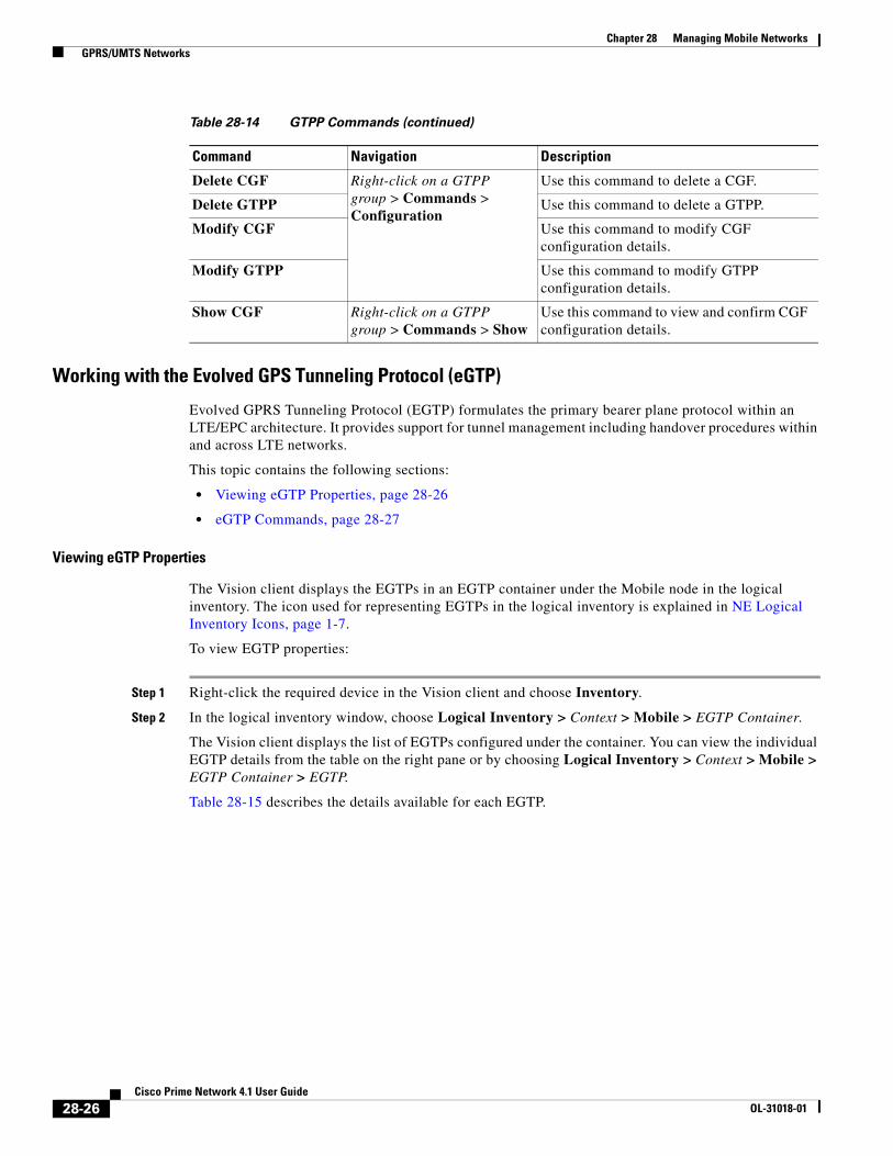
Working with the Evolved GPS Tunneling Protocol (eGTP)
Evolved GPRS Tunneling Protocol (EGTP) formulates the primary bearer plane protocol within an LTE/EPC architecture. It provides support for tunnel management including handover procedures within and across LTE networks.
This topic contains the following sections:
• Viewing eGTP Properties, page 28-26
• eGTP Commands, page 28-27
Viewing eGTP Properties
The Vision client displays the EGTPs in an EGTP container under the Mobile node in the logical inventory. The icon used for representing EGTPs in the logical inventory is explained in NE Logical Inventory Icons, page 1-7.
To view EGTP properties:
Step 1 Right-click the required device in the Vision client and choose Inventory.
Step 2 In the logical inventory window, choose Logical Inventory > Context > Mobile > EGTP Container.
The Vision client displays the list of EGTPs configured under the container. You can view the individual EGTP details from the table on the right pane or by choosing Logical Inventory > Context > Mobile > EGTP Container > EGTP.
Table 28-15 describes the details available for each EGTP.
Delete CGF Right-click on a GTPP group > Commands > Configuration
Use this command to delete a CGF.
Delete GTPP Use this command to delete a GTPP.
Modify CGF Use this command to modify CGF configuration details.
Modify GTPP Use this command to modify GTPP configuration details.
Show CGF Right-click on a GTPP group > Commands > Show
Use this command to view and confirm CGF configuration details.
Table 28-14 GTPP Commands (continued)
Command Navigation Description
28-26Cisco Prime Network 4.1 User Guide
OL-31018-01

Chapter 28 Managing Mobile Networks GPRS/UMTS Networks
eGTP Commands
The following eGTP commands can be launched from the inventory by right-clicking an EGTP and choosing Commands > Configuration. Your permissions determine whether you can run these commands (see ). To find out if a device supports these commands, see the Cisco Prime Network 4.0 Supported Cisco VNEs.
Monitoring the Serving GPRS Support Node (SGSN)
The Serving GPRS Support Node (SGSN) is a very important component of the GPRS network. It is responsible for handling the delivery of data from and to the mobile nodes within its geographical service area, such as packet routing and transfer, mobility management, and authentication of users.
Along with the Radio Access Network (RAN) and Gateway GPRS Support Node (GGSN), the SGSN:
• Communicates with the Home Location Registers (HLR) via a Gr interface and with the mobile Visitor Location Registers (VLR) via a Gs interface to register a subscriber’s equipment or authenticate, retrieve and update the subscriber’s profile information.
Table 28-15 EGTP Properties in Logical Inventory
Field Description
Service Name Name of the EGTP service.
Status Status of the EGTP service.
Message Validation Mode
Mode of message validation for the EGTP service.
Interface Type Interface type for the EGTP service.
Restart Counter Restart counter value for the EGTP service.
GTPC Retransmission Timeout
Control packet retransmission timeout for the EGTP service.
GTPC Max Request Retransmissions
Maximum number of request retransmissions for the EGTP service.
GTPC IP QoS DSCP Value
The IP QoS DSCP value for the EGTP service.
GTPC Echo Indicates whether GTPC echo is configured for the EGTP service or not.
GTPC Echo Interval GTPC echo interval for the EGTP service.
GTPC Echo Mode GTPC echo mode, which could be Dynamic or Default.
GTPC Smooth Factor Smooth factor used in the dynamic echo timer for the EGTP service.
Table 28-16 EGTP Commands
Command Navigation Description
Modify EGTP Right-click on a EGTP group > Commands > Configuration
Use this command to modify EGTP configuration details.
Delete EGTP Use this command to delete the EGTP.
28-27Cisco Prime Network 4.1 User Guide
OL-31018-01

Chapter 28 Managing Mobile Networks GPRS/UMTS Networks
• Supports Gd interface to provide short message service (SMS) and other text-based network services to subscribers.
• Activates and manages IPv4, IPv6 or point-to-point (PPP) type packet data protocol (PDP) contexts for a subscriber session.
• Manages the data plane between the RAN and GGSN providing high speed data transfer with configurable GEA0-3 ciphering.
• Provides mobility management, location management, and session management for the duration of call to ensure smooth handover.
• Provides different types of charging data records (CDR) to attached accounting or billing storage mechanisms
• Provides Communications Assistance for Law Enforcement Act (CALEA) support for lawful intercepts.
Viewing the SGSN Configuration Details
To view the SGSN configuration details:
Step 1 Right-click the required device in the Vision client and choose Inventory.
Step 2 In the logical inventory window, choose Logical Inventory > Context > Mobile > SGSN. The SGSN services configured in Prime Network are displayed in the content pane as shown in the following figure.
Step 3 Under the SGSN node, choose an SGSN service. The SGSN service details are displayed in the content pane.
Table 28-17 describes the SGSN service details.
28-28Cisco Prime Network 4.1 User Guide
OL-31018-01

Chapter 28 Managing Mobile Networks GPRS/UMTS Networks
Table 28-17 SGSN Service Details
Field Description
Service Name The unique name of the SGSN service.
Note You can configure only one SGSN service for a chassis.
Status The status of the SGSN service, which can be any of the following:
• Unknown
• Initiated
• Running
• Down
• Started
• Not Started
SGSN Number The phone number that is associated with the SGSN service.
Core Network ID The network code that identifies the core network tp connect the SGSN service.
Associated SGTP Service
The name of the STGP service and its context associated to the SGSN service. This service is represented in the following format:
<SGTP Service Name>@<SGTP Service Context>
Associated MAP Service
The name of the Mobile Application Part (MAP) service and its context that is associated to the SGSN service. This service is represented in the following format:
<MAP Service Name>@<MAP Service Context>
Note MAP is an SS7 protocol that provides an application layer for the various nodes in GSM and UMTS mobile core networks and GPRS core networks to communicate with each other in order to provide services to mobile phone users. It is an application-layer protocol used to access SGSN service.
Associated HSS Service The name of the Home Subscriber Server (HSS) service and its context that is associated to the SGSN service. This service is represented in the following format:
<HSS Service Name>@<HSS Service Context>
Associated IuPS Service
The name of the IuPS service and its context that is associated to the SGSN service. This service is represented in the following format:
<IuPS Service Name>@<IuPS Service Context>
Note The interface between the RNC and the Circuit Switched Core Network (CS-CN) is called Iu-CS and between the RNC and the Packet Switched Core Network is called Iu-PS
28-29Cisco Prime Network 4.1 User Guide
OL-31018-01
Chapter 28 Managing Mobile Networks GPRS/UMTS Networks
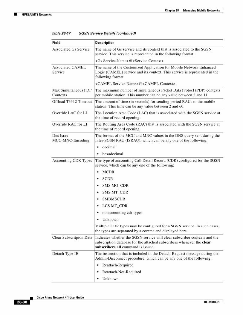
Associated Gs Service The name of Gs service and its context that is associated to the SGSN service. This service is represented in the following format:
<Gs Service Name>@<Service Context>
Associated CAMEL Service
The name of the Customized Application for Mobile Network Enhanced Logic (CAMEL) service and its context. This service is represented in the following format:
<CAMEL Service Name>@<CAMEL Context>
Max Simultaneous PDP Contexts
The maximum number of simultaneous Packet Data Protocl (PDP) contexts per mobile station. This number can be any value between 2 and 11.
Offload T3312 Timeout The amount of time (in seconds) for sending period RAUs to the mobile station. This time can be any value between 2 and 60.
Override LAC for LI The Location Area Code (LAC) that is associated with the SGSN service at the time of record opening.
Override RAC for LI The Routing Area Code (RAC) that is associated with the SGSN service at the time of record opening.
Dns Israu MCC-MNC-Encoding
The format of the MCC and MNC values in the DNS query sent during the Inter-SGSN RAU (ISRAU), which can be any one of the following:
• decimal
• hexadecimal
Accounting CDR Types The type of accounting Call Detail Record (CDR) configured for the SGSN service, which can be any one of the following:
• MCDR
• SCDR
• SMS MO_CDR
• SMS MT_CDR
• SMBMSCDR
• LCS MT_CDR
• no accounting cdr-types
• Unknown
Multiple CDR types may be configured for a SGSN service. In such cases, the types are separated by a comma and displayed here.
Clear Subscritpion Data Indicates whether the SGSN service will clear subscriber contexts and the subscription database for the attached subscribers whenever the clear subscribers all command is issued.
Detach Type IE The instruction that is included in the Detach-Request message during the Admin-Disconnect procedure, which can be any one of the following:
• Reattach-Required
• Reattach-Not-Required
• Unknown
Table 28-17 SGSN Service Details (continued)
Field Description
28-30Cisco Prime Network 4.1 User Guide
OL-31018-01

Chapter 28 Managing Mobile Networks GPRS/UMTS Networks
Gf Timeout Action The action to be taken by the SGSN service when a response is not received from the Equipment Identify Register (EIR) even though a valid EIR configuration exists under the MAP service and the route to the EIR is available. Any one of the following actions is applicable:
• Continue
• Reject
Gf Failure Action The action to be taken by the SGSN service when the EIR is temporarily inaccessible even though a valid EIR configuration exists under the MAP service, which can be any one of the following:
• Continue
• Reject
Reporting Action Event Record
Indicates whether the SGSN service is allowed to enable GGM/SM event logging for 3G services.
Network Global MME ID Management DB
Indicates whether the SGSN service is associated to the Network Global MMEID Management Database, which in turn is configured on the LTE policy.
Tai Management DB Indicates whether the SGSN service is associated to the Tai Management Database, which in turn is configured on the LTE policy.
NRI Values tab
NRI Value The MS assigned value of the Network Resource Identifier (NRI) to retrieve from the P-TSMI, which is used to identify a SGSN service in a pool.
Note This value is unique across all pools.
Connecting Indicates whether the SGSN service will offload subscribers by sending either a “Attach Request” or “RAU Request” message for the corresponding NRI value.
Activating Indicates whether the SGSN service will offload subscribers by sending an “Activate Request” message for the corresponding NRI value.
Profiles tab
Profile No. The type of billing,which can be any one of the following:
• 1—Hot billing
• 2—Flat billing
• 4—Prepaid billing
• 8—Normal billing
• All other profiles from 0-15 are customized billing types.
Buckets Denotes container changes in the Call Detail Record (CDR).
Down Link Octets The downlink traffic volume of the bucket.
Up Link Octets The uplink traffic volume of the bucket.
Total Octets The total traffic volume of the bucket.
Table 28-17 SGSN Service Details (continued)
Field Description
28-31Cisco Prime Network 4.1 User Guide
OL-31018-01

Chapter 28 Managing Mobile Networks GPRS/UMTS Networks
Viewing SGSN Service Properties
You can also view the following configuration details for SGSN service:
• GPRS Mobility Management—GPRS Mobility Management (GMM) is a GPRS signaling protocol that handles mobility issues such as roaming, authentication, and selection of encryption algorithms. GPRS Mobility Management, together with Session Management (GMM/SM) protocol support the mobility of user terminal so that the SGSN can know the location of a mobile station (MS) at any time and to activate, modify and deactivate the PDP sessions required by the MS for the user data transfer. See GPRS Mobility Management Properties, page 28-32.
• NRI Properties—The Network Resource Identifier (NRI) identifies the specific CN node of the pool. The UE derives the NRI from TMSI, P-TMSI, IMSI or IMEI. See NRI Properties, page 28-34.
• Session Management Properties—The SGSN service performs comprehensive session management, including context activation, modification, deactivation, and preservation. It also provides support for IPv4, IPv6, and PPP PDP context types. In addition, the SGSN's intelligent PDP context preservation feature facilitates efficient radio resource utilization. See Session Management Properties, page 28-35.
GPRS Mobility Management Properties
To view the GPRS Mobility Management details:
Step 1 Right-click the required device in the Vision client and choose Inventory.
Step 2 In the logical inventory window, choose Logical Inventory > Context > Mobile > SGSN > GPRS Mobility Management. The GPRS mobility details are displayed in the content pane.
Table 28-18 describes the SGSN service details.
Intervals tab
Prolfile No. The type of billing.
No. of SGSNs The number of changes to the SGSN (inter-SGSN switchovers) resulting in a new Routing Area Identity (RAI) that can occur before closing an accounting record.
Interval The amount of time (in seconds) that must elapse before closing an accounting record.
Down Link Octets The downlink traffic volume reached within the time interval.
Up Link Octets The uplink traffic volume reached within the time interval.
Total Octets The total traffic volume reached within the time interval.
Tarrifs tab
Profile No. The type of billing.
Time (1 - 6) The time-of-day values at different times in a day, which is required to close the current statistics container.
Table 28-17 SGSN Service Details (continued)
Field Description
28-32Cisco Prime Network 4.1 User Guide
OL-31018-01

Chapter 28 Managing Mobile Networks GPRS/UMTS Networks
Table 28-18 GPRS Mobility Management Details
Field Description
Max Identity Retries The maximum number of retransmissions allowed for identity requests. In other words, it relates to the number of retransmissions allowed before failure of the request. This number can be any value between 1 and 10.
Max Page Retries The maximum number of retransmissions allowed for page requests. In other words, it relates to the number of retransmissions allowed before failure of the request. This number can be any value between 1 and 5.
Max PTMSI Reloc Retries
The maximum number of retransmissions allowed for P-TMSI relocation procedure. In other words, it relates to the number of retransmissions allowed before failure of the P-TMSI relocation procedure. This number can be any value between 1 and 10.
Perform Identity After Auth
Indicates whether the SGSN service is allowed to perform an identity check to ascertain the IMSI after an authentication failure on a P-TMSI message.
TRAU Timeout The amount of time (in seconds) that the SGSN service must wait to purge the mobile stations’s data.This timer is started by the SGSN service after completion of the inter-SGSN RAU.
T3302 Timeout The amount of time (in minutes) the SGSN service must wait to attach the GPRS or RAU procedure on the mobile station node before retransmitting the message again. This time can be any value between 1 and 186.
T3312 Timeout The amount of time (in minutes) the SGSN service must wait to initiate the RAU procedure on the network network before retransmitting the message again. This time can be any value between 1 and 186.
T3313 Timeout The amount of time (in seconds) the SGSN service must wait to initiate the GPRS on the network before retransmitting the message again. This time can be any value between 1 and 60.
T3322 Timeout The amount of time (in seconds) the SGSN service must wait to detach the GPRS on the network before retransmitting the message again. This time can be any value between 1 and 20.
T3350 Timeout The amount of time (in seconds) the SGSN service must wait to accept the GPRS attach request, RAU attach request, or reallocation request sent with the P-TSMI/TSMI on the network. This time can be any value between 1 and 20.
T3360 Timeout The amount of time (in seconds) the SGSN service must wait to guard the authentication or cipher request on the network before retransmitting the message again. This time can be any value between 1 and 20.
T3370 Timeout The amount of time (in seconds) the SGSN service must wait for the identity request before retransmitting the message again. This time can be any value between 1 and 20.
Mobile Reachable Timeout
The amount of time (in minutes) the SGSN service must wait to reach a mobile station on the network before retransmitting the message again. This time can be any value between 4 and 4400.
28-33Cisco Prime Network 4.1 User Guide
OL-31018-01

Chapter 28 Managing Mobile Networks GPRS/UMTS Networks
NRI Properties
To view the NRI Properties for an SGSN service:
Step 1 Right-click the required device in the Vision client and choose Inventory.
Step 2 In the logical inventory window, choose Logical Inventory > Context > Mobile > SGSN > NRI Properties. The NRI properties are displayed in the content pane.
Table 28-19 describes the NRI Properties details.
Implicit Detach Timeout
The amount of time (in seconds) the SGSN service must wait for the implicit detach procedure on the network before retransmitting the message again. This time can be any value between 1 and 3600.
Purge Timeout The amount of time (in minutes) the SGSN service must wait to detach the mobility management context on the network before retransmitting the message again. This time can be any value between 1 and 20160.
Table 28-18 GPRS Mobility Management Details (continued)
Field Description
Table 28-19 NRI Properties Details
Field Description
NRI Length The number of bits to be used in P-TMSI to define the NRI, which can be any number between 1 and 6. This length also determines the maximum size of the pool. If you do not configure a length for the NRI, then the default value of zero is considered to be the NRI’s length.
NRI Null Value The value of the null NRI, which is unique across all pool areas. If the NRI null value is 0, it indicates that the keyword is not used. Any value between 1 and 63 is used to identify the SGSN service that is to be used for offloading procedure for SGSN pooling.
Non Broadcast MCC The country code of the mobile, whic is basically the first part of the PLMN ID. This code can be any value between 100 and 999.
Non Broadcast MNC The network code portion of the PLMN ID. This code must be a 2 or 3 digit value between 1 and 999.
Non Broadcast LAC The location area code associated with an RNC. This code must be any value between 1 and 65535.
Non Broadcast RAC The remote area code associated with an RNC. This code can be any value between 1 and 255.
28-34Cisco Prime Network 4.1 User Guide
OL-31018-01

Chapter 28 Managing Mobile Networks GPRS/UMTS Networks
Session Management Properties
To view the Session Management properties for an SGSN service:
Step 1 Right-click the required device in the Vision client and choose Inventory.
Step 2 In the logical inventory window, choose Logical Inventory > Context > Mobile > SGSN > Session Management Properties. The Session Management properties are displayed in the content pane.
Table 28-20 describes the Session Management Properties details.
Monitoring the Iu PS Services
The Radio Network Controller (or RNC) is a governing element in the UMTS radio access network (UTRAN) and is responsible for controlling the Node Bs that are connected to it. This is the point where encryption is done before user data is sent to and from the mobile.
The RNC connects to the Circuit Switched Core Network through Media Gateway (MGW) and to the SGSN (Serving GPRS Support Node) in the Packet Switched Core Network. The interface between the RNC and the Circuit Switched Core Network (CS-CN) is called Iu-CS and between the RNC and the Packet Switched Core Network is called Iu-PS.
The Iu PS interface is very important in the UMTS network and it’s function include:
• Radio Access Bearer (RAB) (wireless access bearing) establishment, maintenance and release process
• Changing-over inside the system, changing-over between systems and Serving Radio Network Subsystem (SRNS) reorientation process
Table 28-20 Session Management Properties Details
Field Description
Max Activate Retries The maximum number of retries to activate PDP context, which can be any value between 1 and 10.
Max Modify Retries The masimum number of retries to modify the PDP context, which can be any value between 1 and 10.
Max Deactivate Retries The maximum number of retries to deactivate PDP context, which can be any value between 1 and 10.
T3385 Timeout The amount of time (in seconds) to wait for a network initiated activate request before it is retransmitted again. This time can be any value between 1 and 60.
T3386 Timeout The amount of time (in seconds) to wait for a network initiated modify request before it is retransmitted again. This time can be any value between 1 and 60.
T3395 Timeout The amount of time (in seconds) to wait for a network initiated deactivate request before it is retransmitted again. This time can be any value between 1 and 60.
Guard Timeout The amount of time (in seconds) for retransmission of a GUARD request, which can be any value between 1 and 60..
28-35Cisco Prime Network 4.1 User Guide
OL-31018-01

Chapter 28 Managing Mobile Networks GPRS/UMTS Networks
• Community radio service process
• Series of general process irrelevant with specific User Equipment (UE)
• Specific signal management for users and separation process on protocol level for each UE
• Transmission process of Network-attached storage (NAS) signal message between UE and CN
• Location service requested from UTRAN to CN and transfer process of position information from UTRAN to CN and resources reserve mechanism
The Iu PS interface mainly analyzes the basic process of the application part of the wireless network, service process of mobility management, service process of conversation management, and statistical values of related Key Performance Indicators (KPI).
Figure 28-3 denotes the architecture of the Iu PS service.
Figure 28-3 Iu PS Service Architecture
To view the Iu PS configuration:
Step 1 Right-click the required device in the Vision client and choose Inventory.
Step 2 In the logical inventory window, choose Logical Inventory > Context > Mobile > Iu PS. The list of Iu PS Services are displayed in the content pane.
Step 3 In the Iu PS node, choose the relevant Iu PS Service. The service details are displayed in the content pane.
Table 28-21 describes the Iu Ps Service details.
28-36Cisco Prime Network 4.1 User Guide
OL-31018-01

Chapter 28 Managing Mobile Networks GPRS/UMTS Networks
Step 4 In the RNCs section, double-click on an RNC ID. The Radio Network Controller Properties window is displayed.
Table 28-21 describes the RNC properties.
Table 28-21 Iu PS Service Details
Field Description
Name The unique name of the Iu PS service.
Status The status of the Iu PS service, which can be any one of the following:
• Initiated
• Running
• Down
• Started
• Not Started
PLMN ID The Public Land Mobile Network (PLMN) ID associated with the Iu PS service, which is basically a combination of the Mobile Country Code (MCC) and the Mobile Network Code (MNC).
Table 28-22 Radio Network Controller Properties
Field Description
ID The unique code of the RNC configuration, which can be any value between 0 and 65535.
Status The status of the RNC configuration, which can be any one of the following:
• Initiated
• Running
• Down
• Started
• Not Started
PLMN ID The PLMN ID associated to the RNC configuration.
Note All the RNCs associated with an Iu PS service will be assigned the same PLMN ID.
Location and Routing Area Codes
28-37Cisco Prime Network 4.1 User Guide
OL-31018-01

Chapter 28 Managing Mobile Networks GPRS/UMTS Networks
To view the associated Iu PS services for a SGSN:
Step 1 Right-click the required device in the Vision client and choose Inventory.
Step 2 In the logical inventory window, choose Logical Inventory > Context > Mobile > SGSN > SGSN service. The SGSN details are displayed in the content pane.
Step 3 In the content pane, click the Iu PS Associations tab.
Table 28-21 describes details relating to Iu Ps Associations for an SGSN.
Working with Small Cell Technologies
With the increased demands on the network, service providers are investing in small cell solutions to help optimize and monetize consumer and business services on mobile devices across 3G and 4G networks.
Prime Network offers a portfolio of licensed small cells for the home and office to support multiple deployment environments and technologies.
A Home Node B (HNB) is the 3GPP's term for a 3G femtocell. It is a small low-power cellular base station that is very useful for use at home or a small business. It uses a broadband network to connect to the service provider’s network.
LAC The Location Area Code applicable to the RNC.
Note The area covered by the PLMN ID is divided into different location areas. Each location area is identified by a unique identifier called the Location Area Identity, which is internationally used for updating location of mobile subscribers.
RACs The Routing Area Code applicable to the RNC, which is used to identify a routing area within a location area.
Table 28-22 Radio Network Controller Properties (continued)
Field Description
Table 28-23 SGSN - Iu PS Association Details
Field Description
Service Name The name of the Iu PS service associated to the SGSN.
Context The context of the Iu PS service.
28-38Cisco Prime Network 4.1 User Guide
OL-31018-01

Chapter 28 Managing Mobile Networks GPRS/UMTS Networks
Note Femtocell is an important technology and service offering that enables new Home and Enterprise service capabilities for Mobile Operators and Converged Mobile Operators (xDSL/Cable/FFTH plus Wireless). The Femtocell network consists of a plug-n-play customer premise device generically called a Home NodeB (HNB) with limited range radio access in home or Enterprise. The HNB will auto-configure itself with the Operators network and the user can start making voice, data and multimedia calls.
The advantage of using HNB is superior coverage and capacity, especially while indoors. It also provides better voice quality and battery life.
Viewing the Home Node B Gateway Details
The Home Node B Gateway is the HNB network access concentrator used to connect the Home Node B (HNBs)/Femto Access Point (FAP) to access the UMTS network through HNB Access Network. It aggregates Home Node-B or Femto Access Points to a single network element and then integrates them into the Mobile Operators Voice, Data and Multimedia networks.
The HNB is connected to an existing residential broadband service and provides 3G radio coverage for 3G handsets.
Figure 28-4 depicts the topology of Home Nobe B Gateway.
Figure 28-4 Home Node B Gateway Topology
Viewing the Home Node B Gateway Configuration
To view the Home Node B Gateway Configuration details:
Step 1 Right-click the required device in the Vision client and choose Inventory.
Step 2 In the logical inventory window, choose Logical Inventory > context > Mobile > HNB GW. The HNB GW configuration details are displayed in the content pane.
28-39Cisco Prime Network 4.1 User Guide
OL-31018-01
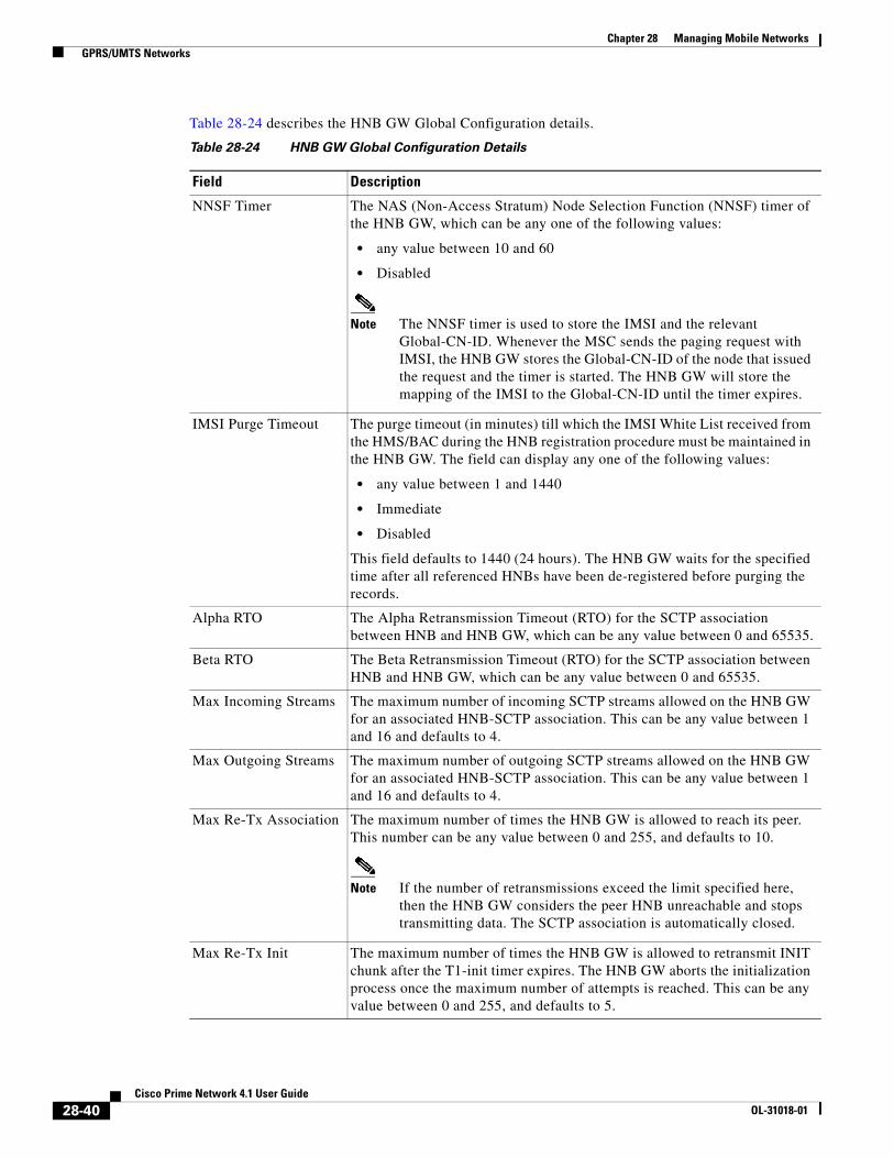
Chapter 28 Managing Mobile Networks GPRS/UMTS Networks
Table 28-24 describes the HNB GW Global Configuration details.
Table 28-24 HNB GW Global Configuration Details
Field Description
NNSF Timer The NAS (Non-Access Stratum) Node Selection Function (NNSF) timer of the HNB GW, which can be any one of the following values:
• any value between 10 and 60
• Disabled
Note The NNSF timer is used to store the IMSI and the relevant Global-CN-ID. Whenever the MSC sends the paging request with IMSI, the HNB GW stores the Global-CN-ID of the node that issued the request and the timer is started. The HNB GW will store the mapping of the IMSI to the Global-CN-ID until the timer expires.
IMSI Purge Timeout The purge timeout (in minutes) till which the IMSI White List received from the HMS/BAC during the HNB registration procedure must be maintained in the HNB GW. The field can display any one of the following values:
• any value between 1 and 1440
• Immediate
• Disabled
This field defaults to 1440 (24 hours). The HNB GW waits for the specified time after all referenced HNBs have been de-registered before purging the records.
Alpha RTO The Alpha Retransmission Timeout (RTO) for the SCTP association between HNB and HNB GW, which can be any value between 0 and 65535.
Beta RTO The Beta Retransmission Timeout (RTO) for the SCTP association between HNB and HNB GW, which can be any value between 0 and 65535.
Max Incoming Streams The maximum number of incoming SCTP streams allowed on the HNB GW for an associated HNB-SCTP association. This can be any value between 1 and 16 and defaults to 4.
Max Outgoing Streams The maximum number of outgoing SCTP streams allowed on the HNB GW for an associated HNB-SCTP association. This can be any value between 1 and 16 and defaults to 4.
Max Re-Tx Association The maximum number of times the HNB GW is allowed to reach its peer. This number can be any value between 0 and 255, and defaults to 10.
Note If the number of retransmissions exceed the limit specified here, then the HNB GW considers the peer HNB unreachable and stops transmitting data. The SCTP association is automatically closed.
Max Re-Tx Init The maximum number of times the HNB GW is allowed to retransmit INIT chunk after the T1-init timer expires. The HNB GW aborts the initialization process once the maximum number of attempts is reached. This can be any value between 0 and 255, and defaults to 5.
28-40Cisco Prime Network 4.1 User Guide
OL-31018-01

Chapter 28 Managing Mobile Networks GPRS/UMTS Networks
Step 3 In the HNB GW node, choose the HNB GW service. The service details are displayed in the content pane.
Table 28-25 describes the HNB GW Service details.
Max Re-Tx Path The maximum number of times the HNB GW is allowed to access an address after the T3-rtx timer expires. This can be any value between 0 and 255, and defaults to 5.
Note Every time the T3-rtx timer expires on an address or the Heartbeat sent to an address is not acknowledged, the error counter for that address increases. Once the error counter exceeds the value specified in this field, the destination address is declared inactive.
IU Connection ID Status
Indicates whether the Iu Connection ID status is enabled.
Table 28-24 HNB GW Global Configuration Details (continued)
Field Description
Table 28-25 HNB GW Service Details
Field Description
Service Name The name of the service, which can be any value between 1 and 63.
CBS Service The name of the Cell Broadcasting Service (CBS) that is configured to the HNB GW.
Note CBS is used to reach millions of subscribers instantly with messages. It is very similar to the SMS technology with the added advantage of sending one message to millions of devices instantly. The message is broadcast to all phones connected to the network in the target area.
IPNE Service The IP Network Enabler (IPNE) service, which defaults to Not Defined.
Note An IPNE service is used to enable or disable IP based network transfer.
RTP Mux Port The port number that is allocated to the Real Time Transport Multiplexing protocol.
RTP Mux Indicates whether Real Time Transport Multiplexing is enabled for the service.
RTP Pool The IP pool configured to allocate the RTP end point address to the session manager, which can be any value between 1 and 31.
28-41Cisco Prime Network 4.1 User Guide
OL-31018-01

Chapter 28 Managing Mobile Networks GPRS/UMTS Networks
You can also view the following configuration details for a HNB GW service:
• Iu/Iuh—The user data is transferred from HNB to HNB GW through the Iuh interface. Iuh interface is used to carry user traffic and control information whereas the Iu interface is used to transfer CS data as well as PS over IP.
• Paging—The Paging memory management scheme is used to store and retrieve data from a secondary storage.
• SCTP—The Stream Control Transmission Protocol (SCTP) is a transport layer that ensures reliable in sequence transport of messages with congestion control like TCP. It also supports framing of individual message boundaries.
• Security—The policies and configurations specific to security and associated to the HNB GW.
• User Equipment—The user equipment must follow a standard registration procedure to connect to the HNB. This registration process also informs the HNB GW about the location of the HNB where the UE is connected.
Mismatch Operations The mismatch handling operation for the HNB GW service.
Open HNB Indicates whether the Open access mode support on the UMTS HNB GW is enabled.
Note An open access mode provides its services to any subscriber in the femto network. An open access HNB can be deployed in public places to increase indoor coverage or off-load traffic from the macro cell.
Hybrid HNB Indicates whether the Hybrid access mode support on the HNB GW is enabled.
Note A hybrid access mode provides its services only to those subscribers who are members of the associated access control database.
Status The status of the HNB GW service, which defaults to Not Defined.
New Call Policy The new call policy for the security gateway associated to the HNB GW service.
GTP Service The GPRS Tunneling Protocol (GTP) service associated to the HNB GW service.
Discard OUI Indicates whether the leading character of the HNB Identification code must be discarded if it contains the Organizational Unique Identifier (OUI).
PLMN Entries
ID The unique code used to identify the Public Land Mobile Network associated to the HNB GW service.
RNC ID The unique code used to identify the Radio Network Controller (RNC) connected to the PLMN.
Table 28-25 HNB GW Service Details (continued)
Field Description
28-42Cisco Prime Network 4.1 User Guide
OL-31018-01

Chapter 28 Managing Mobile Networks GPRS/UMTS Networks
Viewing the Iu and Iuh Configuration Details for a Home Node B Gateway Service
To view the Iu or Iuh Configuration details for a HNB GW service:
Step 1 Right-click the required device in the Vision client and choose Inventory.
Step 2 In the logical inventory window, choose Logical Inventory > context > Mobile > HNB GW > hnb gw service > Iu or Iuh. The relevant configuration details are displayed in the content pane.
Table 28-26 describes the Iu/Iuh configuration details.
Viewing the Paging Configuration for a Home Node B Gateway Service
To view the Paging details for a HNB GW service:
Step 1 Right-click the required device in the Vision client and choose Inventory.
Step 2 In the logical inventory window, choose Logical Inventory > context > Mobile > HNB GW > hnb gw service > Paging. The Paging properties are displayed in the content pane.
Table 28-27 describes the Paging details.
Table 28-26 Iu/Iuh Configuration Details
Field Description
ScptAny The Differentiated Services Code Point (DSCP) markings configured over the Iuh interface.
Protocol The transfer protocol configured for the HNB GW service.
GTPU The Differentiated Services Code Point (DSCP) configured over the Iu or Iuh interface with the GTPU protocol.
RTP The DSCP configured over the Iu or Iuh interface with the RTP protocol.
RTCP The DSCP configured over the Iu or Iuh interface with the RTCP protocol.
Any The DSCP configured over the Iu or Iuh interface with any protocol.
Table 28-27 Paging Details
Field Description
IMSI Life Timer The International Mobile Subscriber Identity (IMSI) purge time for the HNB GW service, which can be any value between 1 and 12.
Note The HNB GW maintains IMSI records for a specified period of time, which is usually measured from the time when the user equipment was last de-registered from the HBN GW.
Handle Unknown IMSI (CS)
Indicates whether the CS domain must process or ignore the paging request from the CN node for an IMSI that is not present in the IMSI DB.
Handle Unknown IMSI (PS)
Indicates whether the PS domain must process or ignore the paging request from the CN node for an IMSI that is not present in the IMSI DB.
Last HNB Timeout (CS) The last known HNB Timeout for the CS domain, which can be any value between 1 and 30.
Last HNB Timeout (PS) The last known HNB Timeout for the PS domain, which can be any value between 1 and 30.
28-43Cisco Prime Network 4.1 User Guide
OL-31018-01

Chapter 28 Managing Mobile Networks GPRS/UMTS Networks
Viewing the SCTP Configuration for a Home Node B Gateway Service
To view the SCTP Configuration details for a HNB GW service:
Step 1 Right-click the required device in the Vision client and choose Inventory.
Step 2 In the logical inventory window, choose Logical Inventory > context > Mobile > HNB GW > hnb gw service > SCTP. The SCTP properties are displayed in the content pane.
Table 28-28 describes the SCTP details.
Fanout Paging Timeout (CS)
The fanout paging Timeout for the CS domain, which can be any value between 1 and 30.
Fanout Paging Timeout (PS)
The fanout paging Timeout for the PS domain, which can be any value between 1 and 30.
Table 28-27 Paging Details (continued)
Field Description
Table 28-28 SCTP Details
Field Description
Checksum The type of checksum used to increase data integrity of an SCTP packet, which can be any one of the following:
• adler32
• crc32
Connection Timeout The SCTP association idle timeout (in seconds).
Cookie Life Time The lifetime of the SCTP cookie (in milliseconds).
Heartbeat Timer The timer (in milliseconds) of the SCTP heartbeat.
Note The SCTP heartbeat is sent to a peer to determine reachability. If an acknowledgement is not received from the peer within the specified time, the peer is considered unreachable and further requests are not sent.
Max MTU Size The maximum size (in bytes) of the Maximum Transmission Unit (MTU) for the SCTP streams allowed by the template, which can be any value between 508 and 65535.
Min MTU Size The minimum size (in bytes) of the Maximum Transmission Unit (MTU) for the SCTP streams allowed by the template, which can be any value between 508 and 65535.
Start Max MTU The starting size (in bytes) of the Maximum Transmission Unit (MTU) for the SCTP streams allowed by the template, which can be any value between 508 and 65535.
RTO Initial The initial time (in milliseconds) for the SCTP Retransmission Timeouts (RTO) allowed by the template, which can be any value between 1 and 1200.
RTO Max The maximum time (in milliseconds) for the SCTP Retransmission Timeouts (RTO) allowed by the template, which can be any value between 5 and 1200.
28-44Cisco Prime Network 4.1 User Guide
OL-31018-01
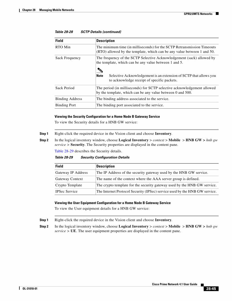
Chapter 28 Managing Mobile Networks GPRS/UMTS Networks
Viewing the Security Configuration for a Home Node B Gateway Service
To view the Security details for a HNB GW service:
Step 1 Right-click the required device in the Vision client and choose Inventory.
Step 2 In the logical inventory window, choose Logical Inventory > context > Mobile > HNB GW > hnb gw service > Security. The Security properties are displayed in the content pane.
Table 28-29 describes the Security details.
Viewing the User Equipment Configuration for a Home Node B Gateway Service
To view the User equipment details for a HNB GW service:
Step 1 Right-click the required device in the Vision client and choose Inventory.
Step 2 In the logical inventory window, choose Logical Inventory > context > Mobile > HNB GW > hnb gw service > UE. The user equipment properties are displayed in the content pane.
RTO Min The minimum time (in milliseconds) for the SCTP Retransmission Timeouts (RTO) allowed by the template, which can be any value between 1 and 50.
Sack Frequency The frequency of the SCTP Selective Acknowledgement (sack) allowed by the template, which can be any value between 1 and 5.
Note Selective Acknowledgement is an extension of SCTP that allows you to acknowledge receipt of specific packets.
Sack Period The period (in milliseconds) for SCTP selective acknowledgement allowed by the template, which can be any value between 0 and 500.
Binding Address The binding address associated to the service.
Binding Port The binding port associated to the service.
Table 28-28 SCTP Details (continued)
Field Description
Table 28-29 Security Configuration Details
Field Description
Gateway IP Address The IP Address of the security gateway used by the HNB GW service.
Gateway Context The name of the context where the AAA server group is defined.
Crypto Template The crypto template for the security gateway used by the HNB GW service.
IPSec Service The Internet Protocol Security (IPSec) service used by the HNB GW service.
28-45Cisco Prime Network 4.1 User Guide
OL-31018-01
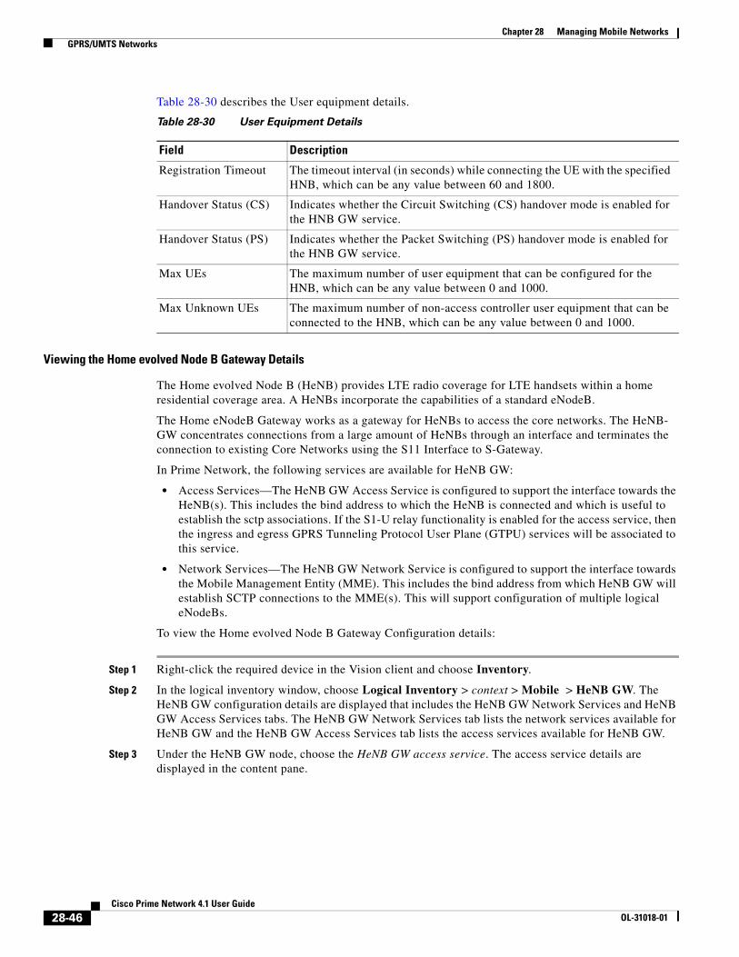
Chapter 28 Managing Mobile Networks GPRS/UMTS Networks
Table 28-30 describes the User equipment details.
Viewing the Home evolved Node B Gateway Details
The Home evolved Node B (HeNB) provides LTE radio coverage for LTE handsets within a home residential coverage area. A HeNBs incorporate the capabilities of a standard eNodeB.
The Home eNodeB Gateway works as a gateway for HeNBs to access the core networks. The HeNB- GW concentrates connections from a large amount of HeNBs through an interface and terminates the connection to existing Core Networks using the S11 Interface to S-Gateway.
In Prime Network, the following services are available for HeNB GW:
• Access Services—The HeNB GW Access Service is configured to support the interface towards the HeNB(s). This includes the bind address to which the HeNB is connected and which is useful to establish the sctp associations. If the S1-U relay functionality is enabled for the access service, then the ingress and egress GPRS Tunneling Protocol User Plane (GTPU) services will be associated to this service.
• Network Services—The HeNB GW Network Service is configured to support the interface towards the Mobile Management Entity (MME). This includes the bind address from which HeNB GW will establish SCTP connections to the MME(s). This will support configuration of multiple logical eNodeBs.
To view the Home evolved Node B Gateway Configuration details:
Step 1 Right-click the required device in the Vision client and choose Inventory.
Step 2 In the logical inventory window, choose Logical Inventory > context > Mobile > HeNB GW. The HeNB GW configuration details are displayed that includes the HeNB GW Network Services and HeNB GW Access Services tabs. The HeNB GW Network Services tab lists the network services available for HeNB GW and the HeNB GW Access Services tab lists the access services available for HeNB GW.
Step 3 Under the HeNB GW node, choose the HeNB GW access service. The access service details are displayed in the content pane.
Table 28-30 User Equipment Details
Field Description
Registration Timeout The timeout interval (in seconds) while connecting the UE with the specified HNB, which can be any value between 60 and 1800.
Handover Status (CS) Indicates whether the Circuit Switching (CS) handover mode is enabled for the HNB GW service.
Handover Status (PS) Indicates whether the Packet Switching (PS) handover mode is enabled for the HNB GW service.
Max UEs The maximum number of user equipment that can be configured for the HNB, which can be any value between 0 and 1000.
Max Unknown UEs The maximum number of non-access controller user equipment that can be connected to the HNB, which can be any value between 0 and 1000.
28-46Cisco Prime Network 4.1 User Guide
OL-31018-01

Chapter 28 Managing Mobile Networks GPRS/UMTS Networks
Table 28-31 describes the HeNB GW Access Services details.
Step 4 Under the selected HeNB GW access service, choose S1 U Relay Configuration. The relay configuration details are displayed in the content pane.
Note This node is available only if the S1U Relay Status is enabled for an access service.
Table 28-32 describes the S1 U Relay Configuration details.
Step 5 Under the HeNB GW node, choose the HeNB GW network service. The network service details are displayed in the content pane.
Table 28-31 HeNB GW Access Service Details
Field Description
Access Service Name The name of the HeNB GW access service configured on the device.
Status The status of the access service, which can be any one of the following:
• Initiated
• Started
• Running
• Not Started
• Down
SCTP IP Address The SCTP IP Address allocated by the access service to which the HeNB is binded.
SCTP Port The SCTP port allocated by the access service.
MME Group The unique code denoting the MME Group that is applicable to the access service.
MME Code The unique MME Code that is applicable to the access service.
PLMN ID The Public Land Mobile Network (PLMN) ID that is applicable to the access service.
S1U Relay Status Indicates whether the S1U Relay is enabled or disabled on the HeNB GW.
Table 28-32 S1 U Relay Configuration Details
Field Description
GTPU Access Service The GTPU Access Service available in the HeNB GW. Clicking this link will display the relevant service under the GTPU node.
GTPU Network Service The GTPU network Service available in HeNB GW. Clicking this link will display the relevant service under the GTPU node.
Downlink QoS The type of the Downlink DSCP QoS applicable to the S1U Relay on the HeNB GW. For example, be, af11, af12, af13, ef.
Uplink QoS The type of Uplink DSCP QoS applicable to the S1U Relay on the HeNB GW. For example, af22, af23, af42, af43, ef.
28-47Cisco Prime Network 4.1 User Guide
OL-31018-01

Chapter 28 Managing Mobile Networks GPRS/UMTS Networks
Table 28-33 describes the HeNB GW Network Service details.
Table 28-33 HeNB GW Network Service Details
Field Description
Network Service Name The name of the HeNB GW network service configured on the device.
Status The status of the network service, which can be any one of the following:
• Initiated
• Started
• Running
• Not Started
• Down
Cell Configuration
PLMN ID The Public Land Mobile Network (PLMN) ID that is applicable to the network service.
Cell ID The evolved Node B identification code that is applicable to the network service.
Note The eNodeB ID allows the HeNB GW to present itself as one or more eNodeBs towards the MME. It is the hardware that is connected to the mobile phone network that communicates directly with the mobile handsets.
SCTP IP Address The SCTP IP Address applicable to the network service, which represents the bind address to which the HeNB connects and establishes the SCTP associations.
SCTP Port The SCTP Port applicable to the network service, which helps the HeNB to connect and establish SCTP connection.
TAI List DB The Tracking Area Identifier (TAI) List applicable to the network service.
Note Each eNode broadcasts a special tracking area code (TAC) that denotes the tracking area to which the eNode belongs to. The TAI is basically a combination of the PLMN ID and TAC ID.
MME Pool Name The MME Pool Name applicable to the network service.
Note The MME Pool Name contains a list of MMEs, which is the key control-node for the LTE access network. It is responsible for idle mode user equipment, tracking and paging procedure including retransmissions.
28-48Cisco Prime Network 4.1 User Guide
OL-31018-01
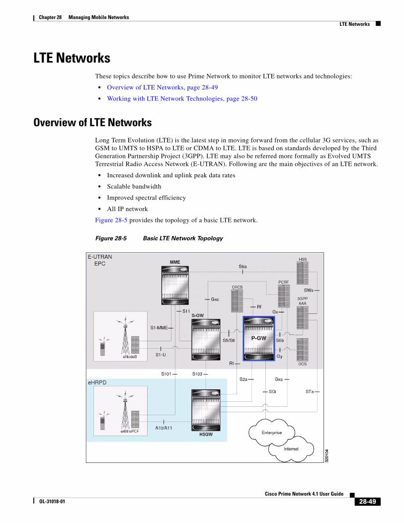
Chapter 28 Managing Mobile Networks LTE Networks
LTE NetworksThese topics describe how to use Prime Network to monitor LTE networks and technologies:
• Overview of LTE Networks, page 28-49
• Working with LTE Network Technologies, page 28-50
Overview of LTE NetworksLong Term Evolution (LTE) is the latest step in moving forward from the cellular 3G services, such as GSM to UMTS to HSPA to LTE or CDMA to LTE. LTE is based on standards developed by the Third Generation Partnership Project (3GPP). LTE may also be referred more formally as Evolved UMTS Terrestrial Radio Access Network (E-UTRAN). Following are the main objectives of an LTE network.
• Increased downlink and uplink peak data rates
• Scalable bandwidth
• Improved spectral efficiency
• All IP network
Figure 28-5 provides the topology of a basic LTE network.
Figure 28-5 Basic LTE Network Topology
28-49Cisco Prime Network 4.1 User Guide
OL-31018-01
Chapter 28 Managing Mobile Networks LTE Networks
Working with LTE Network TechnologiesThe E-UTRAN uses a simplified single node architecture consisting of the eNodeBs (E-UTRAN Node B). The eNB communicates with the Evolved Packet Core (EPC) using the S1 interface, specifically with the Mobility Management Entity (MME) and Serving Gateway (S-GW) using S1-U interface. The PDN Gateway (P-GW0 provides connectivity to the external packet data networks.
Following sections provide more details on these services and their support in Prime Network:
• Monitoring System Architecture Evolution Networks (SAE-GW), page 28-50
• Working with PDN-Gateways (P-GW), page 28-52
• Working with Serving Gateway (S-GW), page 28-54
• Viewing QoS Class Index to QoS (QCI-QoS) Mapping, page 28-56
• Viewing Layer 2 Tunnel Access Concentrator Configurations (LAC), page 28-56
• Monitoring the HRPD Serving Gateway (HSGW), page 28-61
• Monitoring Home Agent (HA), page 28-73
• Monitoring the Foreign Agent (FA), page 28-79
• Monitoring Evolved Packet Data Gateway (ePDG), page 28-90
• Monitoring Packet Data Serving Node (PDSN), page 28-100
• Viewing the Local Mobility Anchor Configuration (LMA), page 28-114
Monitoring System Architecture Evolution Networks (SAE-GW)
Systems Architecture Evolution (SAE) has a flat all-IP architecture with separation of control plane and user plane traffic. The main component of SAE architecture is the Evolved Packet Core (EPC), also known as SAE Core. The EPC serves as an equivalent to GPRS networks by using its subcomponents Mobility Management Entities (MMEs), Serving Gateway (S-GW), and PDN Gateway (P-GW).
Mobility Management Entity (MME)
MME is the key control node for a Long Term Evolution (LTE) access network. It is responsible for idle mode User Equipment (UE) tracking and paging procedure including retransmissions. It is involved in the bearer activation/deactivation process and is also responsible for choosing the S-GW for a UE at the initial attach and at time of intra-LTE handover involving Core Network (CN) node relocation. The MME also provides the control plane function for mobility between LTE and 2G/3G access networks with the S3 interface terminating at the MME from the SGSN. See
Serving Gateway (S-GW)
The S-GW routes and forwards user data packets, while also acting as the mobility anchor for the user plane during inter-eNodeB handovers and as the anchor for mobility between LTE and other 3GPP technologies. For idle state UEs, the S-GW terminates the downlink data path and triggers paging when downlink data arrives for the UE. It manages and stores UE contexts, such as parameters of the IP bearer service, network internal routing information, and so on. It also performs replication of the user traffic in case of lawful interception. For more information, see Working with Serving Gateway (S-GW), page 28-54.
28-50Cisco Prime Network 4.1 User Guide
OL-31018-01

Chapter 28 Managing Mobile Networks LTE Networks
PDN Gateway (P-GW)
The P-GW provides connectivity from the UE to external packet data networks by being the point of exit and entry of traffic for the UE. A UE may have simultaneous connectivity with more than one P-GW for accessing multiple PDNs. The P-GW performs policy enforcement, packet filtering for each user, charging support, lawful interception, and packet screening. Another key role of the P-GW is to act as the anchor for mobility between 3GPP and non-3GPP technologies such as WiMAX and 3GPP2. For more information, see Working with PDN-Gateways (P-GW), page 28-52.
Running S-GW and P-GW services together as a SAE-GW provides the following benefits:
• Higher capacity—For a UE with one PDN connection that is passing through standalone S-GW and P-GW services consumes 2 license units because both S-GW and P-GW services account for it separately. SAE-GW as a single node consumes only one license unit for the same, thus increasing the capacity.
• Cohesive configuration—Configuration and management of SAE-GW as a node is simpler to follow and logical to explain.
See Viewing SAE-GW Properties, page 28-51 for details on how to view SAE-GW properties in the Vision client.
Viewing SAE-GW Properties
The Vision client displays the SAE-GWs in a SAE-GW container under the Mobile node in the logical inventory. The icon used for representing SAE-GW in the logical inventory is explained in NE Logical Inventory Icons, page 1-7.
To view SAE-GW properties:
Step 1 Right-click the required device in the Vision client and choose Inventory.
Step 2 In the logical inventory window, choose Logical Inventory > Context > Mobile > SAE-GW Container.
The Vision client displays the list of SAE-GW services configured under the container. You can view the individual SAE-GW service details from the table on the right pane or by choosing Logical Inventory > Context > Mobile > SAE-GW Container > SAE-GW.
Table 28-34 describes the details available for each SAE-GW.
Table 28-34 SAE-GW Properties in Logical Inventory
Field Description
Service Name Name of the SAE-GW service.
Service ID ID of the SAE-GW service.
Status Status of the SAE-GW service.
P-GW Service The P-GW service associated with the SAE-GW.
S-GW Service The S-GW service associated with the SAE-GW.
New Call Policy Specifies if the new call related behavior of SAE-GW service is enabled or disabled, when duplicate sessions with same IP address request is received.
28-51Cisco Prime Network 4.1 User Guide
OL-31018-01

Chapter 28 Managing Mobile Networks LTE Networks
SAE-GW Commands
The following SAE-GW commands can be launched from the inventory by right-clicking a SAE-GW and choosing Commands > Configuration. Your permissions determine whether you can run these commands (see ). To find out if a device supports these commands, see the Cisco Prime Network 4.0 Supported Cisco VNEs.
Working with PDN-Gateways (P-GW)
A PDN Gateway (P-GW) is the node that terminates the SGi interface towards the PDN. If a user equipment (UE) is accessing multiple PDNs, there may be more than one P-GW for that UE. The P-GW provides connectivity to the UE to external packet data networks by being the point of exit and entry of traffic for the UE. A UE may have simultaneous connectivity with more than one P-GW for accessing multiple PDNs.
The P-GW facilitates policy enforcement, packet filtering for each user, charging support, lawful interception, and packet screening. The features of P-GW include:
• Integration of multiple core network functions in a single node
• Multiple instances of P-GW can enable call localization and local breakout
• High performance across all parameters like, signaling, throughput, density, and latency
• Integrated in-line services
• Support for enhanced content charging, content filtering with blacklisting, dynamic network-based traffic optimization, application detection and optimization, stateful firewall, NAT translation, and lawful intercept
• High-availability helps to ensure subscriber satisfaction
The following topics explain how to work with P-GW in the Vision client:
• Viewing P-GW Properties, page 28-52
• P-GW Commands, page 28-53
Viewing P-GW Properties
The Vision client displays the P-GWs in a P-GW container under the Mobile node in the logical inventory. The icon used for representing P-GW in the logical inventory is explained in NE Logical Inventory Icons, page 1-7.
To view P-GW properties:
Step 1 Right-click the required device in the Vision client and choose Inventory.
Step 2 In the logical inventory window, choose Logical Inventory > Context > Mobile > P-GW Container.
Table 28-35 SAE-GW Commands
Command Navigation Description
Create SAE GW Logical Inventory > Right-click on a context > Commands > Configuration
Use this command to create SAE GW.
Delete SAE GW Right-click on a SAE GW > Commands > Configuration
Use this command to delete or modify the configuration details for a SAE GW.
Modify SAE GW
28-52Cisco Prime Network 4.1 User Guide
OL-31018-01

Chapter 28 Managing Mobile Networks LTE Networks
The Vision client displays the list of P-GW services configured under the container. You can view the individual P-GW service details from the table on the right pane or by choosing Logical Inventory > Context > obile > P-GW Container > P-GW.
Table 28-36 describes the details available for each P-GW.
Step 3 If the P-GW is associated with PLMNs, you can view the details of the PLMNs on clicking the specified P-GW.
P-GW Commands
The following P-GW commands can be launched from the inventory by right-clicking a P-GW and choosing Commands > Configuration. Your permissions determine whether you can run these commands (see ). To find out if a device supports these commands, see the Cisco Prime Network 4.0 Supported Cisco VNEs.
Table 28-36 P-GW Properties in Logical Inventory
Field Description
Service Name Name of the P-GW service.
Service Status Status of the P-GW service.
EGTP Service Evolved GPRS Tunneling Protocol (EGTP) service associated with the P-GW. EGTP provides tunneling support for the P-GW.
GGSN Service GGSN service associated with the P-GW.
LMA Service Local Mobility Anchor (LMA) that facilitates proxy mobile IP on the P-GW.
QCI QoS Mapping Table Name
Table name of QoS class indices that enfore QoS parameters.
New Call Policy Specifies if the new call related behavior of P-GW service is enabled or disabled, when duplicate sessions with same IP address request is received.
Session Delete Delay Timeout
Duration, in seconds, to retain a session before terminating it.
SAE-GW Service Systems Architecture Evolution (SAE) gateway service associated with the P-GW.
Table 28-37 P-GW Commands
Command Navigation Description
Create P-GW PLMN Right-click on a P-GW service > Commands > Configuration
Use this command to create a PLMN for P-GW.
Delete P-GW Use this command to delete a P-GW.
Modify P-GW Use this command to modify the configuration details for a P-GW.
28-53Cisco Prime Network 4.1 User Guide
OL-31018-01

Chapter 28 Managing Mobile Networks LTE Networks
Working with Serving Gateway (S-GW)
In a Long Term Evolution (LTE) / Systems Architecture Evolution (SAE) network, a Serving Gateway (S-GW) acts as a demarcation point between the Radio Access Network (RAN) and core network, and manages user plane mobility. It serves as the mobility anchor when terminals move across areas served by different eNode-B elements in Evolved UMTS Terrestrial Radio Access Network (E-UTRAN), as well as across other 3GPP radio networks such as GSM EDGE Radio Access Network(GERAN) and UTRAN. S-GW buffers downlink packets and initiates network-triggered service request procedures. Other functions include lawful interception, packet routing and forwarding, transport level packet marking in the uplink and the downlink, accounting support for per user, and inter-operator charging. The S-GW routes and forwards user data packets, while also acting as the mobility anchor for the user plane during inter-eNode-B handovers and as the anchor for mobility between LTE and other 3GPP technologies.
For idle state user equipment (UE), the S-GW terminates the downlink data path and triggers paging when downlink data arrives for the UE. It manages and stores UE contexts, such as parameters of the IP bearer service, network internal routing information, and so on. It also performs replication of the user traffic in case of lawful interception.
The following topics provide details on how to work with S-GWs in the Vision client:
• Viewing S-GW Properties, page 28-54
• S-GW Commands, page 28-55
Viewing S-GW Properties
The Vision client displays the S-GWs in a S-GW container under the Mobile node in the logical inventory. The icon used for representing S-GW in the logical inventory is explained in NE Logical Inventory Icons, page 1-7.
To view S-GW properties:
Step 1 Right-click the required device in the Vision client and choose Inventory.
Step 2 In the logical inventory window, choose Logical Inventory > Context > Mobile > S-GW Container.
The Vision client displays the list of S-GW services configured under the container. You can view the individual S-GW service details from the table on the right pane or by choosing Logical Inventory > Context > Mobile > S-GW Container > S-GW.
Table 28-38 describes the details available for each S-GW.
Table 28-38 S-GW Properties in Logical Inventory
Field Description
Service Name Name of the S-GW service.
Service Status Status of the S-GW service.
Accounting Context Name of the context configured on the system that processes accounting for service requests handled by the S-GW service.
Accounting GTPP Group
Name of the accounting GTPP group associated with the S-GW service. This will hold the configured GTPP server group (for GTPP servers redundancy) on a S-GW service for CGF accounting functionality.
Accounting Mode Accounting protocol, which could be GTPP or Radius-Diameter.
28-54Cisco Prime Network 4.1 User Guide
OL-31018-01

Chapter 28 Managing Mobile Networks LTE Networks
Step 3 If the S-GW is associated with PLMNs, you can view the PLMN entries on clicking the specified S-GW.
S-GW Commands
The following S-GW commands can be launched from the inventory by right-clicking an S-W and choosing Commands > Configuration. Your permissions determine whether you can run these commands (see ). To find out if a device supports these commands, see the Cisco Prime Network 4.0 Supported Cisco VNEs. (
Egress Protocol Egress protocol used for the S-GW service, which could be GTP, GTP-PMIP, or PMIP.
Ingress EGTP Service Ingress EGTP service associated with the S-GW. EGTP provides tunneling support for the S-GW.
Egress Context Context used for S-GW service egress.
Egress ETGP Service Ingress EGTP service associated with the S-GW. EGTP provides tunneling support for the S-GW.
Egress Mag Service Mobile Access Gateway (MAG) egress service through calls are routed to the S-GW.
IMS Authorization Service
IMS authorization service associated with the S-GW.
Accounting Policy Accounting policy configured for the S-GW.
New Call Policy Specifies if the new call related behavior of S-GW service is enabled or disabled, when duplicate sessions with same IP address request is received.
QCI QoS Mapping Table
Table name of QoS class indices that enfore QoS parameters.
SAE GW Service Systems Architecture Evolution (SAE) gateway service associated with the S-GW.
Table 28-38 S-GW Properties in Logical Inventory (continued)
Field Description
Table 28-39 S-GW Commands
Command Navigation Description
Create S-GW PLMN Right-click on a S-GW service > Commands > Configuration
Use this command to create a PLMN for S-GW.
Delete S-GW Use this command to delete a S-GW.
Modify S-GW Use this command to modify the configuration details for a S-GW.
28-55Cisco Prime Network 4.1 User Guide
OL-31018-01

Chapter 28 Managing Mobile Networks LTE Networks
Viewing QoS Class Index to QoS (QCI-QoS) Mapping
The QoS Class Index (QCI) to QoS mapping configuration mode is used to map Dices to enforceable QoS parameters. Mapping can occur between the RAN and the S-GW, the MME, and/or the P-GW in an LTE network or between the RAN and the harped Serving Gateway (HSGW) in an eHRPD network. This is a global configuration. These maps can be imported by P-gateway and S-gateway to enforce these parameters on upstream/downstream traffic.
The Vision client displays the QCI-QoS mapping information under the Mobile node in the logical inventory. See Figure 28-20.
Note QCI-QoS mapping is applicable only for the ‘local’ context in the logical inventory.
To view QCI-QoS mapping:
Step 1 Right-click the required device in the Vision client and choose Inventory.
In the logical inventory window, choose Logical Inventory > local > Mobile > QCI-QoS Mapping.
the Vision client displays the list of QCI-QoS mapping records configured under the container. You can view the individual record from the table on the right pane or by choosing Logical Inventory > Context > Mobile > QCI-QoS Mapping > Mapping Name.
Table 28-40 describes the QCI-QoS mapping details.
Viewing Layer 2 Tunnel Access Concentrator Configurations (LAC)
In computer networking, Layer 2 Tunneling Protocol (L2TP) is a tunneling protocol used to support virtual private networks (VPNs) or as part of the delivery of services by ISPs. It does not provide any encryption or confidentiality by itself; it relies on an encryption protocol that it passes within the tunnel
Table 28-40 QCI-QoS Mapping
Field Description
Mapping Name Name of the QCI-QoS mapping record.
QCI-QoS Mapping Table
QCI Number QCI number.
QCI Type QCI type.
Uplink DSCP marking to be used for encapsulation and UDP for uplink traffic
Downlink DSCP marking to be used for encapsulation and UDP for downlink traffic
Max Packet Delay Maximum packet delay, in milliseconds, that can be applied to the data.
Max Error Rate Maximum error loss rate of non congestion related packet loss.
Delay Class Packet delay.
Precedence Class Indicates packet precedence.
Reliability Class Indicates packet reliability.
Traffic Policing Interval Traffic policing interval.
28-56Cisco Prime Network 4.1 User Guide
OL-31018-01

Chapter 28 Managing Mobile Networks LTE Networks
to provide privacy. The entire L2TP packet, including payload and L2TP header, is sent within a User Datagram Protocol (UDP) datagram. It is common to carry Point-to-Point Protocol (PPP) sessions within an L2TP tunnel.
The two endpoints of an L2TP tunnel are called the LAC (L2TP Access Concentrator) and the LNS (L2TP Network Server). The LAC is the initiator of the tunnel while the LNS is the server, which waits for new tunnels. Once a tunnel is established, the network traffic between the peers is bidirectional.
LAC allows users and telecommuters to connect to their corporate intranets or extranets using L2TP. In other words, it forwards packets to and from the LNS and a remote system. It connects to the LNS using a local area network or wide area network and directs subscriber sessions into L2TP tunnels based on the domain of each session. Figure 28-6 denotes the LAC architecture.
Figure 28-6 LAC Architecture
The packets that are exchanged within an L2TP tunnel can be categorized as control packets and data packets.
To view the LAC configuration details:
Step 1 Right-click the required device in the Vision client and choose Inventory.
Step 2 In the logical inventory window, choose Logical Inventory > Context > LAC. The list of LAC services configured in Prime Network is displayed in the content pane.
Step 3 From the LAC node, choose an LAC service. The LAC service details are displayed in the content pane as shown in Figure 28-7.
CPE
PPP in L2TPsessions
Retail LNSprovider
Provider 1
Provider 2
Provider n
3204
87
L2TP sessionsare terminatedand placed in a VRF
Wholesale LNSprovider
Cisco 10000 ESR
VRF 1
VRF n
VRF 2
LAC IPtransportnetwork
Access network(ATM or Ethernet)
28-57Cisco Prime Network 4.1 User Guide
OL-31018-01

Chapter 28 Managing Mobile Networks LTE Networks
Figure 28-7 LAC Service Details
Table 28-41 displays the LAC configuration details.
Table 28-41 LAC Configuration Details
Field Description
Service Name The unique identification string for the LAC service.
Status The status of the LAC service, which can be any one of the following:
• Initiated
• Running
• Down
• Started
• Nonstarted
• Unknown
Local IP Address The local IP address bound with the LAC service.
Max Sessions The maximum number of subscribers connected to this service at any time, which can be any value between 1 and 2500000. This field defaults to 2500000.
Max Tunnels The maximum length (in bytes) of the tunnel challenge.
Note The tunnel challenge is basically used to authenticate tunnels at the time of creation.
28-58Cisco Prime Network 4.1 User Guide
OL-31018-01

Chapter 28 Managing Mobile Networks LTE Networks
Max Sessions Per Tunnel
The maximum number of sessions that can be handled by a single tunnel at one point of time, which can be any value between 1 and 65535. This field defaults to 512.
Max Retransmissions The maximum number of times a control message is retransmitted to a peer, before clearing the tunnel and its sessions.
Keep Alive Interval The amount of time after which a keep alive message is sent.
Control Receive Window
The number of control messages the remote peer LNS can send before an acknowledgement is received.
Max Tunnel Challenge Length
The maximum length (in bytes) of the tunnel challenge.
First Retransmission Timeout
The initial timeout before retransmitting a control message.
Note Each tunnel maintains a queue of control messages that must be transmitted to its peer. If an acknowledgement is not received after the specified period, then the control message is retransmitted.
Max Retransmission Timeout
The maximum amount of time between two retransmitted messages.
Load Balancing The type of load balancing to select LNS for the LAC service, which can be any one of the following:
• Balanced
• Prioritized
• Random
Tunnel Selection Key The selection key to create tunnels between the L2TP service and the LNS server, based on the value of the \u2015Tunnel-Server-Auth-ID\u2016 attribute received from the AAA server.
New Call Policy The new call policy for busy-out conditions, which can be any one of the following:
• None
• Accept
• Reject
Data Sequence Numbers
Indicates whether data sequence numbering for sessions that use the current LAC service is enabled. This option is enabled by default.
Tunnel Authentication Indicates whether tunnel authentication is enabled.
Note If this option is enabled, a configured shared secret is used to ensure that the LAC service is communicating with an authorized peer LNS. The shared secret is configured by the command in the LAC service configuration mode, the command in the subscriber configuration mode, or the Tunnel-Password attribute in the subscribers RADIUS profile.
Table 28-41 LAC Configuration Details (continued)
Field Description
28-59Cisco Prime Network 4.1 User Guide
OL-31018-01

Chapter 28 Managing Mobile Networks LTE Networks
Proxy LCP Authentication
Indicates whether the option to send proxy LCP authentication parameters to the LNS is enabled.
Attribute Hiding Indicates whether certain attributes in control messages sent from the LAC to the LNS is hidden.
Note The LAC hides these attributes only if the tunnel authentication option is enabled between the LAC and LNS.
Framed IP Address Snoop
Indicates whether the LAC can detect IPCP packets exchanged between the mobile node and the LNS and extract the framed-I-address assigned to the mobile node.
Note The address that is extracted is reported in the accounting start/stop messages and will be displayed for each subscriber session.
Allow AAA Assigned Host Name
Indicates whether the Tunnel-Client-Auth ID assigned by AAA is used as the Host name AVP in the L2TP tunnel setup message.
Note If the tunnel parameters are not received from the RADIUS server, then the parameters configured in APN are considered for LNS peer selection. When the parameters in APN are considered, the local-hostname configured with the APN command for the LNS peer is used as the LAC Host name.
Allow APN in Called Number
Indicates whether the APN name in Called number AVP is sent as part of the Incoming-Call Request (ICRQ) message sent to the LNS. If this keyword is not configured, then the Called number AVP will not be included in the ICRQ message sent to the LNS>
Single UDP Port Mode Indicates whether the standard L2TP port 1701 is used as a source port for all L2TP control and data packets that originate from the LAC node.
Peer LNS Address
Peer LNS Address The IP address of the peer LNS for the current LAC service, which is usually in standard IPv4 dotted decimal notation.
Preference The priority of the peer LNS, which can be any number between 1 and 128. This priority is used when multiple peer LNS are configured.
Crypto Map The name of crypto map that is configured for the selected context.
Description The description of the specified peer LNS.
Table 28-41 LAC Configuration Details (continued)
Field Description
28-60Cisco Prime Network 4.1 User Guide
OL-31018-01

Chapter 28 Managing Mobile Networks LTE Networks
Monitoring the HRPD Serving Gateway (HSGW)
The HRPD Serving Gateway (HSGW) is a component in the evolved High Rate Packet Data (eHRPD) mobile network. It is an evolution option for CDMA operators that helps ensure converged mobility and management between HRPD and LTE networks.
The HSGW terminates the eHRPD access network interface from the Evolved Access Network (eAN) or Evolved Packet Core Function (ePCF) and routes UE-originated or terminated packet data traffic. It provides interworking with the eAN/ePCF and the PDN Gateway (P-GW) within the Evolved Packet Core (EPC) or LTE/SAE core network.
HSGW performs the following functions:
• Mobility anchoring for inter-eAN handoffs
• Transport level packet marking in the uplink and the downlink. For example, setting the DiffServ Code Point, based on the QCI of the associated EPS bearer
• Uplink and downlink charging per UE, PDN, and QCI
• Downlink bearer binding based on policy information
• Uplink bearer binding verification with packet dropping of UL traffic that does not comply with established uplink policy
• MAG functions for S2a mobility (i.e., Network-based mobility based on PMIPv6)
• Support for IPv4 and IPv6 address assignment
• EAP Authenticator function
• Policy enforcement functions defined for the Gxa interface
• Robust Header Compression (RoHC)
• Support for VSNCP and VSNP with UE
• Support for packet-based or HDLC-like framing on auxiliary connections
• IPv6 SLACC, generating RAs responding to RSs
An HSGW also establishes, maintains and terminates link layer sessions to UEs. The HSGW functionality provides interworking of the UE with the 3GPP EPS architecture and protocols. This includes support for mobility, policy control and charging (PCC), access authentication, and roaming. The HSGW also manages inter-HSGW handoffs.
The topology of the HSGW network is shown in the following figure:
28-61Cisco Prime Network 4.1 User Guide
OL-31018-01

Chapter 28 Managing Mobile Networks LTE Networks
Figure 28-8 HSGW Topology
Basic Features of HSGW
The basic features supported by HSGW can be categorized as follows:
• Authentication
• IP Address Allocation
• Quality of Service
• AAA, Policy and Charging
The Authentication features supported by HSGW are:
• EAP over PPP
• UE and HSGW negotiates EAP as the authentication protocol during LCP
• HSGW is the EAP authenticator
• EAP-AKA’ (trusted non-3GPP access procedure) as specified in TS 33.402
• EAP is performed between UE and 3GPP AAA over PPP/STa
The IP Address Allocation features supported by HSGW are:
• Support for IPv4 and IPv6 addressing
• Types of PDNs - IPv4, IPv6 or IPv4v6
• IPv6 addressing
– Interface Identifier assigned during initial attach and used by UE to generate it’s link local address
eNodeB
S1-U
S-GW
S1-MME
S11
MME
MN
3204
90
PCRF
eANePCFMN
eHRPD
S5/S8Gy
S6a
S6a
A10/A11
HSGW
S101 S103 S2a STa
SWx
SGi
Gxa
Gx
Rf
Rf
Gxc3GPPAAA
HSS
OCS
OFCS
P-GW
Internet
Enterprise
28-62Cisco Prime Network 4.1 User Guide
OL-31018-01

Chapter 28 Managing Mobile Networks LTE Networks
– HSGW sends the assigned /64 bit prefix in RA to the UE
– Configure the 128-bits IPv6 address using IPv6 SLAAC (RFC 4862)
– Optional IPv6 parameter configuration via stateless DHCPv6(Not supported)
• IPv4 address
– IPv4 address allocation during attach
– Deferred address allocation using DHCPv4(Not supported)
– Option IPv4 parameter configuration via stateless DHCPv4(Not supported)
The Quality of Service features supported by HSGW include:
• HRPD Profile ID to QCI Mapping
• DSCP Marking
• UE Initiated Dedicated Bearer Resource Establishment
• QCI to DSCP Mapping
The AAA, Policy and Charging features supported by HSGW include:
• EAP Authentication (STa)
• Rf Diameter Accounting
• AAA Server Groups
• Dynamic Policy and Charging: Gxa Reference Interface
• Intelligent Traffic Control
Viewing the HSGW Configuration
To view the HSGW configuration:
Step 1 Right-click the required device in the Vision client and choose Inventory.
Step 2 In the logical inventory window, choose Logical Inventory > Context > Mobile > HSGW. The list of HSGW services configured in Prime Network are displayed in the content pane.
Step 3 From the HSGW node, choose a HSGW service. The HSGW service details are displayed in the content pane as shown in Figure 28-9.
28-63Cisco Prime Network 4.1 User Guide
OL-31018-01

Chapter 28 Managing Mobile Networks LTE Networks
Figure 28-9 HSGW Service Details
Table 28-42 displays the HSGW service details.
Table 28-42 HSGW Service details
Field Description
Name The name of the HSGW service.
Status The status of the service, which can be any one of the following:
• Started
• Not Started
This field defaults to Not Started.
Bind Address The IPv4 address to which the service is bound to. This field defaults to Null if binding is not done.
Local IP Port The User Datagram Protocol (UDG) port for the R-P interface of the IP socket.
Maximum Subscribers The maximum number of subscriber sessions that the service can support.
MAG Service The Mobile Access Gateway (MAG) service associated with the HSGW service. Clicking this link will take you to the relevant MAG service under the MAG node.
DNS PGW Context The location of the Domain Name System (DNS) client, which is used to identify the Fully Qualified Domain Name (FQDN) for the peer P-GW.
Registration Lifetime The registration lifetime that is configured for all the subscribers.
Setup Timeout The maximum amount of time (in seconds) allowed for session setup.
28-64Cisco Prime Network 4.1 User Guide
OL-31018-01

Chapter 28 Managing Mobile Networks LTE Networks
You can also view the following configuration details for a HSGW service:
• A10/A11 Properties—The A10/A11 interface (also known as R-P interface for RAN-to-PDSN) supports the A10 protocol for user data transport between the PCF and PDSN, and the A11 protocol for the associated signaling. A11 signaling messages are also used for passing accounting related and other information from the PCF to the PDSN. The A10/A11 interfaces support mobility between
Context Retention Timeout
The maximum number of time (in seconds) that the UE session context is maintained by the HSGW service before it is torn down.
Note The UE session context includes the Link Control Protocol (LCP), authentication and the A10 session context for a given UE.
Maximum Retransmission
The maximum number of times the HSGW service will try to communicate with the eAN or PCF before it declares it as unreachable.
Network Initiated QoS Indicates whether the Network Initiated QoS feature is supported by the HSGW service.
Unauthorized Flow QoS Timeout
The amount of time (in seconds) the service must wait before a QoS update is triggered to downgrade an unauthorized flow.
SPI tab
SPI Number The unique Security Parameter Index (SPI) number, which indicates a security context between the services.
Remote Address The IP address of the source service, which can be an IPv4 dotted decimal notation or IPv6 colon separated notation.
Zone ID The PCF zone id that must be configured for the HSGW service.
Netmask The subnet mask of the service.
Hash Algorithm The hash algorithm used between the source and destination services.
Time Stamp Tolerance The difference (tolerance) in timestamps that is acceptable. If the actual difference in the timestamps exceeds this difference, then the session is rejected.
Replay Protection The replay-protection scheme that must be implemented by the service.
Description The description of the SPI.
PLMN tab
PLMN ID The unique id of the Public Land Mobile Network (PLMN), which is used to determine if a mobile station is visiting, roaming, or belongs to the network.
Primary Indicates whether the PLMN Id must be used as the default and primary ID.
Overload Policies tab
IP Address The IP address of an alternate PDSN, which is in the IPv4 dotted decimal notation.
Weight The weightage of the IP address, which determines the order in which the IP address is used in case of multiple IP addresses.
Table 28-42 HSGW Service details (continued)
Field Description
28-65Cisco Prime Network 4.1 User Guide
OL-31018-01
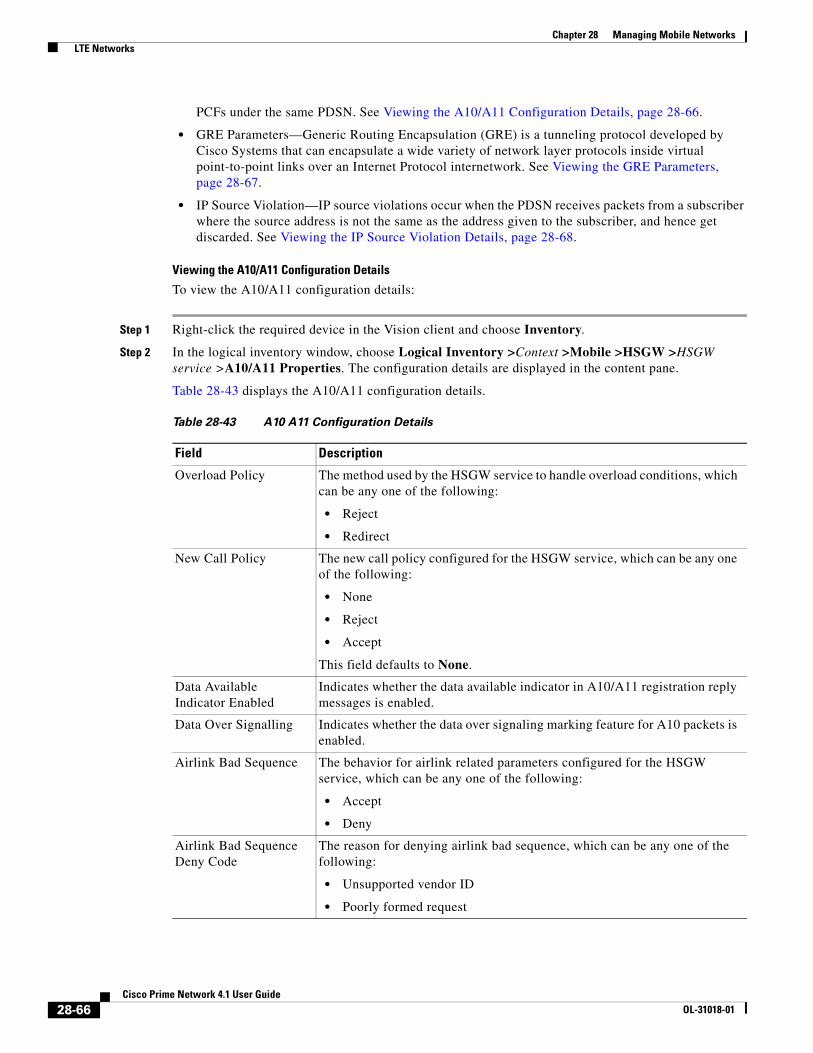
Chapter 28 Managing Mobile Networks LTE Networks
PCFs under the same PDSN. See Viewing the A10/A11 Configuration Details, page 28-66.
• GRE Parameters—Generic Routing Encapsulation (GRE) is a tunneling protocol developed by Cisco Systems that can encapsulate a wide variety of network layer protocols inside virtual point-to-point links over an Internet Protocol internetwork. See Viewing the GRE Parameters, page 28-67.
• IP Source Violation—IP source violations occur when the PDSN receives packets from a subscriber where the source address is not the same as the address given to the subscriber, and hence get discarded. See Viewing the IP Source Violation Details, page 28-68.
Viewing the A10/A11 Configuration Details
To view the A10/A11 configuration details:
Step 1 Right-click the required device in the Vision client and choose Inventory.
Step 2 In the logical inventory window, choose Logical Inventory >Context >Mobile >HSGW >HSGW service >A10/A11 Properties. The configuration details are displayed in the content pane.
Table 28-43 displays the A10/A11 configuration details.
Table 28-43 A10 A11 Configuration Details
Field Description
Overload Policy The method used by the HSGW service to handle overload conditions, which can be any one of the following:
• Reject
• Redirect
New Call Policy The new call policy configured for the HSGW service, which can be any one of the following:
• None
• Reject
• Accept
This field defaults to None.
Data Available Indicator Enabled
Indicates whether the data available indicator in A10/A11 registration reply messages is enabled.
Data Over Signalling Indicates whether the data over signaling marking feature for A10 packets is enabled.
Airlink Bad Sequence The behavior for airlink related parameters configured for the HSGW service, which can be any one of the following:
• Accept
• Deny
Airlink Bad Sequence Deny Code
The reason for denying airlink bad sequence, which can be any one of the following:
• Unsupported vendor ID
• Poorly formed request
28-66Cisco Prime Network 4.1 User Guide
OL-31018-01
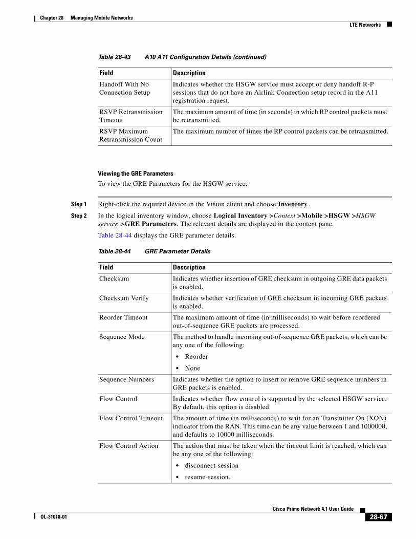
Chapter 28 Managing Mobile Networks LTE Networks
Viewing the GRE Parameters
To view the GRE Parameters for the HSGW service:
Step 1 Right-click the required device in the Vision client and choose Inventory.
Step 2 In the logical inventory window, choose Logical Inventory >Context >Mobile >HSGW >HSGW service >GRE Parameters. The relevant details are displayed in the content pane.
Table 28-44 displays the GRE parameter details.
Handoff With No Connection Setup
Indicates whether the HSGW service must accept or deny handoff R-P sessions that do not have an Airlink Connection setup record in the A11 registration request.
RSVP Retransmission Timeout
The maximum amount of time (in seconds) in which RP control packets must be retransmitted.
RSVP Maximum Retransmission Count
The maximum number of times the RP control packets can be retransmitted.
Table 28-43 A10 A11 Configuration Details (continued)
Field Description
Table 28-44 GRE Parameter Details
Field Description
Checksum Indicates whether insertion of GRE checksum in outgoing GRE data packets is enabled.
Checksum Verify Indicates whether verification of GRE checksum in incoming GRE packets is enabled.
Reorder Timeout The maximum amount of time (in milliseconds) to wait before reordered out-of-sequence GRE packets are processed.
Sequence Mode The method to handle incoming out-of-sequence GRE packets, which can be any one of the following:
• Reorder
• None
Sequence Numbers Indicates whether the option to insert or remove GRE sequence numbers in GRE packets is enabled.
Flow Control Indicates whether flow control is supported by the selected HSGW service. By default, this option is disabled.
Flow Control Timeout The amount of time (in milliseconds) to wait for an Transmitter On (XON) indicator from the RAN. This time can be any value between 1 and 1000000, and defaults to 10000 milliseconds.
Flow Control Action The action that must be taken when the timeout limit is reached, which can be any one of the following:
• disconnect-session
• resume-session.
28-67Cisco Prime Network 4.1 User Guide
OL-31018-01

Chapter 28 Managing Mobile Networks LTE Networks
Viewing the IP Source Violation Details
To view the IP source Violation configuration details:
Step 1 Right-click the required device in the Vision client and choose Inventory.
Step 2 In the logical inventory window, choose Logical Inventory >Context >Mobile >HSGW >HSGW service >IP Source Violation. The configuration details are displayed in the content pane.
Table 28-45 displays the IP Source Violation configuration details.
Protocol Type The tunnel type for the GRE routing. This field defaults to Any.
Is 3GPP Extension Header QoS Marking
Indicates whether the 3GG Extension Header QoS Marking is enabled for the selected HSGW feature.
Note If this feature is enabled and the PCF negotiation feature is enabled in A11 RRQ, then the HSGW will include QoS optional data attribute in the GRE 3GPP2 Extension Header.
MTU The maximum transmission unit (MTU) for packets accessing the APN.
IP Header DSCP The Differential Service Code Point (DSCP) value in the IP header that marks the GRE IP Header encapsulation. This can be any value between 0x0F and 0X3F, and defaults to 0X0F.
IP Header DSCP Packet Type
Indicates whether the IP Header DSCP Value packet type is specified for the packets, which can be any one of the following:
• all-control-packets—Indicates that DSCP marking for GRE IP header encapsulation will be applied for all control packets for the session.
• setup-packets-only—Indicates that DSCP marking for GRE IP header encapsulation willbe applied only for session setup packets.
GRE Segmentation Indicates whether segmentation of GRE packets is enabled. By default, this option is disabled.
Table 28-44 GRE Parameter Details (continued)
Field Description
Table 28-45 IP Source Violation Configuration Details
Field Description
Renegotiation Limit The number of source violations that are allowed within a specified detection period, after which a PPP renegotiation is forced.
Drop Limit The number of source violations that are allowed within a specified detection period, after which a call disconnect is forced.
28-68Cisco Prime Network 4.1 User Guide
OL-31018-01

Chapter 28 Managing Mobile Networks LTE Networks
Configuration Commands for HSGW
The following HSGW commands can be launched from the logical inventory by choosing the Context > Commands > Configuration or Context > Commands > Show. Your permissions determine whether you can run these commands (see ). To find out if a device supports these commands, see the Cisco Prime Network 4.1 Supported Cisco VNEs.
Clear On Valid PDU Indicates whether the service must reset the renegotiation limit and drop limit counters if a properly addressed packet is received.
Period The amount of time (in seconds) for the source violation detection period. Once this value is reached, the drop limit and renegotiation limit counters are decremented.
Table 28-45 IP Source Violation Configuration Details
Field Description
Table 28-46 HSGW Configuration Commands
Command Navigation Description
Create HSGW Right-click context > Commands > Configuration
Use this command to create a new HSGW service.
Modify HSGW
Delete HSGW
Expand HSGW node > Right-click HSGW service > Commands > Configuration
Use this command to modify/delete the configuration details of an HSGW service.
Show HSGW Expand HSGW node > Right-click HSGW service > Commands > Show
Use this command to view and confirm the configuration details of an HSGW service.
Create SPI Expand HSGW node > right-click HSGW service > Commands > Configuration
Use this command to create a new Security Parameter Index (SPI) for the HSGW service.
Modify SPI
Delete SPI
Expand HSGW node > HSGW service > In content pane, click SPI tab > Right-click on SPI No. field > Commands > Configuration
Use this command to modify/delete the SPI configuration details for the HSGW service.
Create PLMN entries
Expand HSGW node > Right-click HSGW service > Commands > Configuration
Use this command to create a new Public Land Mobile Network (PLMN) for the HSGW service.
Modify PLMN entries
Delete PLMN entries
Expand HSGW node > HSGW service > In content pane, click PLMN tab > Right-click on PLMN ID field > Commands > Configuration
Use this command to modify/delete the PLMN configuration details for the HSGW service.
Create Overload Policy
Expand HSGW node > right-click HSGW service > Commands > Configuration
Use this command to create a new overload policy for the HSGW service.
Modify Overload Policy
Delete Overload Policy
Expand HSGW node > HSGW service > In content pane, click Overload Policies tab > Right-click on IP address field > Commands > Configuration
Use this command to modify/delete the overload policy details for the HSGW service.
28-69Cisco Prime Network 4.1 User Guide
OL-31018-01

Chapter 28 Managing Mobile Networks LTE Networks
Viewing the MAG Configuration for HSGW
A Mobile Access Gateway (MAG) performs mobility-related signaling on behalf of the mobile nodes (MN) attached to its access links. MAG is the access router for the MN; that is, the MAG is the first-hop router in the localized mobility management infrastructure
A MAG performs the following functions:
• Obtains an IP address from a Local Mobility Anchor (LMA) and assigns it to an MN
• Retains the IP address of an MN when the MN roams across MAGs
• Tunnels traffic from an MN to LMA
To view the MAG configuration details:
Step 1 Right-click the required device in the Vision client and choose Inventory.
Step 2 In the logical inventory window, choose Logical Inventory > Context > Mobile > MAG > MAG service. The configuration details are displayed in the content pane.
Table 28-47 displays the configuration details for a MAG service.
Modify A10 A11 Interface
Expand HSGW node > HSGW service > Right-click A10/A11 Properties > Commands > Configuration
Use this command to modify the A10/A11 configuration details for the HSGW service.
Modify GRE Expand HSGW node > HSGW service > Right-click GRE > Commands > Configuration
Use this command to modify the GRE configuration details for the HSGW service.
Modify IP Source Violation
Expand HSGW node > HSGW service > Right-click IP Source Violation > Commands > Configuration
Use this command to modify the IP source violation details for the HSGW service.
Table 28-46 HSGW Configuration Commands
Command Navigation Description
Table 28-47 MAG Service Configuration Details
Field Description
Name The unique name of the MAG service.
Status The status of the MAG service, which can be any one of the following:
• Started
• Not Started
This field defaults to Not Started.
Bind Address The IP address to which the MAG service is bound to.
Maximum Subscribers The maximum number of subscribers supported by the service.
PMIP Maximum Retransmission
The maximum number of times the MAG service will communicate with the LMA, before it is declared unreachable.
28-70Cisco Prime Network 4.1 User Guide
OL-31018-01
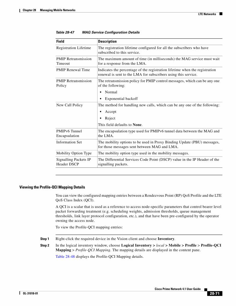
Chapter 28 Managing Mobile Networks LTE Networks
Viewing the Profile-QCI Mapping Details
You can view the configured mapping entries between a Rendezvous Point (RP) QoS Profile and the LTE QoS Class Index (QCI).
A QCI is a scalar that is used as a reference to access node-specific parameters that control bearer level packet forwarding treatment (e.g. scheduling weights, admission thresholds, queue management thresholds, link layer protocol configuration, etc.), and that have been pre-configured by the operator owning the access node.
To view the Profile-QCI mapping entries:
Step 1 Right-click the required device in the Vision client and choose Inventory.
Step 2 In the logical inventory window, choose Logical Inventory > local > Mobile > Profile > Profile-QCI Mapping > Profile-QCI Mapping. The mapping details are displayed in the content pane.
Table 28-48 displays the Profile-QCI Mapping details.
Registration Lifetime The registration lifetime configured for all the subscribers who have subscribed to this service.
PMIP Retransmission Timeout
The maximum amount of time (in milliseconds) the MAG service must wait for a response from the LMA.
PMIP Renewal Time Indicates the percentage of the registration lifetime when the registration renewal is sent to the LMA for subscribers using this service.
PMIP Retransmission Policy
The retransmission policy for PMIP control messages, which can be any one of the following:
• Normal
• Exponential backoff
New Call Policy The method for handling new calls, which can be any one of the following:
• Accept
• Reject
This field defaults to None.
PMIPv6 Tunnel Encapsulation
The encapsulation type used for PMIPv6 tunnel data between the MAG and the LMA.
Information Set The mobility options to be used in Proxy Binding Update (PBU) messages, for those messages sent between MAG and LMA.
Mobility Option Type The mobility option type used in the mobility messages.
Signalling Packets IP Header DSCP
The Differential Services Code Point (DSCP) value in the IP Header of the signalling packets.
Table 28-47 MAG Service Configuration Details
Field Description
28-71Cisco Prime Network 4.1 User Guide
OL-31018-01

Chapter 28 Managing Mobile Networks LTE Networks
Configuration Commands for MAG
The following MAG commands can be launched from the logical inventory by choosing the Context > Commands > Configuration or Context > Commands > Show. Your permissions determine whether you can run these commands (see ). To find out if a device supports these commands, see the Cisco Prime Network 4.0 Supported Cisco VNEs.
Table 28-48 Profile-QCI Mapping Details
Field Description
Profile Name The name of the Profile-QCI Mapping profile that is associated with the HSGW.
Profile-QCI Mapping Table
QCI ID The QCI ID to which the profile is mapped.
Profile ID The profile ID to which the QCI ID is mapped.
Uplink GBR The Guaranteed Bit Rate (GBR) for the uplink data flow, which can be any value between 0 and 4294967295.
Downlink GBR The GBR for the downlink data flow, which can be any value between 0 and 4294967295.
Uplink MBR The Maximum Bit Rate (MBR) for the uplink data flow, which can be any value between 0 and 4294967295.
Downlink MBR The MBR for the downlink data flow, which can be any value between 0 and 4294967295.
Priority Level The priority level of the profile for the QCI, which can be any value between 1 and 15.
Preemption Capability The preemption capability of the profile.
Table 28-49 MAG Configuration Commands
Command Navigation Description
Create MAG Right-click context > Commands > Configuration
Use this command to create a new Mobile Access Gateway (MAG) service for the selected context.
Modify MAG
Delete MAG
Expand MAG Node > Right-click MAG service > Commands > Configuration
Use this command to modify the MAG configuration details/delete the MAG profile for the selected context.
Show MAG Expand MAG Node > Right-click MAG service > Commands > Show
Use this command to view and confirm the configuration details for the selected MAG service.
Create Profile ID QCI Mapping
Right-click on context > Commands > Configuration
Use this command to create a QCI profile.
28-72Cisco Prime Network 4.1 User Guide
OL-31018-01

Chapter 28 Managing Mobile Networks LTE Networks
Monitoring Home Agent (HA)
A Home Agent (HA) stores information about the mobile nodes whose permanent home address is in the home agent’s network. When a node wants to communicate with the mobile node, it sends packets to the permanent address. Because the home address logically belongs to the network associated with the HA, normal IP routing mechanisms forward these packets to the home agent.
When a mobile node moves out of the home network, the HA still manages to deliver the packets to the mobile node. This is done by interacting with the Foreign Agent (FA) that the mobile node is communicating with using the Mobile IP (MIP) Standard. Such transactions are performed through the use of virtual private networks that create MIP tunnels between the HA and FA. The following figure displays the configuration between the FA and HA network deployment.
Figure 28-10 Home Agent Topology
When functioning as a HA, the system can either be located within the carrier’s 3G network or in an external enterprise or ISP network. The FA terminates the mobile subscriber’s PPP session, and then routes data to and from the appropriate HA on behalf of the subscriber.
Delete Profile ID QCI Mapping
Expand Profile node > Right-click profile name > Commands > Configuration
Use this command to delete QCI profile.
Create Profile Expand Profile node > Right-click profile name > Commands > Configuration
Use this command to create an entry for the QCI mapping profile.
Modify Profile
Delete Profile
Expand Profile node > profile > Right-click on profile entry > Commands > Configuration
Use these commands to modify/delete the entry for the QCI mapping profile.
Table 28-49 MAG Configuration Commands
Command Navigation Description
RadioTower
BSC/PCFMN32
0490
PDSN/FA
Foreign AAA
AAA AAA
R-P P1 P1 PDN
HA CN
Home AAA
IP Network Internetor PDN
28-73Cisco Prime Network 4.1 User Guide
OL-31018-01

Chapter 28 Managing Mobile Networks LTE Networks
In accordance with Request for Comments (RFC) 2002, the FA is responsible for mobile node registration with, and tunneling of data traffic from/to the subscriber’s home network. The HA is also responsible for tunneling traffic, but it maintains subscriber location information separately in the Mobility Binding Records (MBR).
Viewing the Home Agent Configuration
To view the Home Agent configuration:
Step 1 Right-click the required device in the Vision client and choose Inventory.
Step 2 In the logical inventory window, choose Logical Inventory > Context > Mobile > Home Agent. The list of home agent services configured in Prime Network are displayed in the content pane.
Step 3 From the Home Agent node, choose a home agent service. The home agent service details are displayed in the content pane as shown in Figure 28-11.
Figure 28-11 Home Agent Service Details
Table 28-50 displays the Home Agent service details.
28-74Cisco Prime Network 4.1 User Guide
OL-31018-01

Chapter 28 Managing Mobile Networks LTE Networks
Table 28-50 Home Agent Service Details
Field Description
Service Name The name of the home agent service.
Status The status of the home agent service, which can be any one of the following:
• Down
• Running
• Initiated
• Unknown
This field defaults to Down.
Default Subscriber The name of the subscriber template that is applied to the subscribers.
Local IP Port The User Datagram Protocol (UDP) port for the R-P interface of the IP socket. This IP port can be any value between 1 and 65535 and defaults to 699.
Bind Address The IP address to which the service is bound to. This can be any address in the IPV4/IPv6 range.
MIP NAT Traversal Indicates whether the acceptance of UDP tunnels for NAT traversal is enabled.
Max. Subscribers The maximum subscriber sessions that could be supported.
Force UDP Tunnel Indicates whether HA would accept requests when Network Address Translation (NAT) is not detected but the Force bit is set in the Registration Request (RRQ) with the UDP Tunnel Request.
Simultaneous Bindings The maximum number of care of addresses that can be simultaneously bound for the same user identified by Network Access Identifier (NAI) and Home address.
Destination Context The name of the context to assign to the subscriber, after authentication.
A11 Signalling Packets IP Header DSCP
The Differential Services Code Point (DSCP) value in the IP header.
Registration Life Time The registration lifetime configured for all the subscribers to the service.
GRE Encapsulation Without Key
Indicates whether Generic Routing Encapsulation (GRE) without encapsulation key is used during Mobile IP sessions with FA.
Idle Time Out The method the HA service uses to determine the time to reset a session idle timer, which can be any one of the following:
• Aggressive
• Handoff
• Normal
SPI List The Security Parameter Index (SPI) between the HA service and the FA.
Optimize Tunnel Reassembly
Indicates whether the option to optimize tunnel reassembly is enabled.
Wi-Max 3GPP Indicates whether the Worldwide Interoperability for Microwave Acces (Wi-Max)-3GPP option is enabled for the Home agent service.
Setup Time Out The maximum time (in seconds) allowed for session setup.
28-75Cisco Prime Network 4.1 User Guide
OL-31018-01

Chapter 28 Managing Mobile Networks LTE Networks
Viewing the AAA Configuration for Home Agent Service
In order to support Packet Data Serving Node (PDSN), FA, and HA functionality, the system must be configured with at least one source context and at least two destination contexts as shown in the following figure.
The source context will facilitate the PDSN service(s), and the R-P interfaces. The AAA context will be configured to provide foreign/home AAA functionality for subscriber sessions and facilitate the AAA interfaces.
To view the AAA configuration:
Reverse Tunnel Indicates whether reverse tunnel feature is enabled for the home agent feature.
Note A reverse tunnel is a tunnel that starts at the care-of address of the mobile node and terminates at the home agent. A mobile node can request a reverse tunnel between the foreign agent and the home agent when the mobile node registers.
Min. Life Time The minimum registration life time for a mobile IP session.
GRE Encapsulation With Key
Indicates whether GRE is used during mobile IP sessions with an FA.
FA HA SPIs / MN HA SPIs tab
SPI Number The number to indicate the security context between services.
Remote Address The IP address of the source service.
Hash Algorithm The hash algorithm used between the source and destination services.
Time Stamp Tolerance The acceptable allowable difference in time stamps. If this difference is exceeded, then the session is rejected.
Replay Protection The replay protection scheme that should be implemented by the service.
Permit Any Hash Algorithm
Indicates whether verification of MN-HA authenticator using other hash algorithms is allowed, on failure of the configured hash algorithm.
Note This field is available only in the MN HA SPIs tab.
Description The description of the SPI.
IPSEC Crypto Maps
Map Name The name of the crypto map that is configured in the same context that defines the IPSec tunnel properties.
Peer FA Address The IP address of the Peer FA to which the IPSEC SA will be established.
Skey Expiry The expiry information of the secret key.
Table 28-50 Home Agent Service Details (continued)
Field Description
28-76Cisco Prime Network 4.1 User Guide
OL-31018-01

Chapter 28 Managing Mobile Networks LTE Networks
Step 1 In the logical inventory window, choose Logical Inventory > Context > Mobile > Home Agent > Home agent service > AAA. The AAA configuration details are displayed in the content pane.
Table 28-51 displays the AAA configuration for a home agent service.
Viewing the GRE Configuration for Home Agent Service
To view the GRE configuration:
Step 1 In the logical inventory window, choose Logical Inventory > Context > Mobile > Home Agent > Home agent service > GRE. The GRE configuration details are displayed in the content pane.
Table 28-52 displays the GRE configuration for a home agent service.
Table 28-51 AAA Configuration for Home Agent Service
Field Description
AAA Context The AAA context for the home agent service. Click this link to view the relevant AAA context.
AAA Accounting Indicates whether the Home Agent can send AAA accounting information for subscriber sessions.
AAA Accounting Group
The AAA Accounting group for the Home agent service.
AAA Distributed MIP Keys
Indicates the usage of AAA distributed MIP keys for authenticating RRQ for WiMax HA calls.
DMU Refresh Key Indicates whether the Home Agent is allowed to retrieve the MN-HA key again from the AAA during the call and use this freshly retrieved key value to recheck authentication.
IMSI Authentication Indicates whether MN-AAA or MN-FAC extensions are present in the RRQ.
MN HA Authentication Type
Indicates whether the HA service looks for an MN-HA authentication in the RRQ.
MN AAA Authentication Type
The method used to send authentication request to AAA for each re-registration attempt.
Note The initial registration request and de-registrations are handled normally.
PMIP Authentication Indicates whether the HA service looks for an PMIP authentication in the RRQ.
Stale Key Disconnect Indicates whether the call must be disconnected immediately on failure of MN-HA authentication.
Skew Lifetime The IKE pre-shared key\u2018s time skew.
28-77Cisco Prime Network 4.1 User Guide
OL-31018-01

Chapter 28 Managing Mobile Networks LTE Networks
Viewing the Policy Configuration for Home Agent Service
To view the Policy configuration:
Step 1 In the logical inventory window, choose Logical Inventory > Context > Mobile > Home Agent > Home agent service > Policy. The Policy configuration details are displayed in the content pane.
Table 28-53 displays the Policy configuration for a home agent service.
Viewing the Registration Revocation Details for a Home Agent Service
To view the Registration revocation configuration details:
Step 1 In the logical inventory window, choose Logical Inventory > Context > Mobile > Home Agent > Home agent service > Registration Revocation. The configuration details are displayed in the content pane.
Table 28-54 displays the Registration Revocation configuration for a home agent service.
Table 28-52 GRE Configuration for Home Agent Service
Field Description
Checksum Indicates whether insertion of GRE checksum in outgoing GRE data packets is enabled.
Checksum Verify Indicates whether verification of GRE checksum in incoming GRE packets is enabled.
Reorder Timeout The maximum amount of time (in milliseconds) to wait before reordered out-of-sequence GRE packets are processed.
Sequence Mode The method to handle incoming out-of-sequence GRE packets, which can be any one of the following:
• Reorder
• None
Sequence Numbers Indicates whether the option to insert or remove GRE sequence numbers in GRE packets is enabled.
Table 28-53 Policy Configuration for Home Agent Service
Field Description
BC Response Code The response code for a binding cache (BC) query result in response to a network failure or error.
NW-Reachability Policy
The action to be taken on detection of an upstream network-reachability failure.
Over Load Policy The overload policy within the HA service.
New Call Policy The new call policy within the HA service.
Over Load Redirect / NW-Reachability Redirect
IP Address The IP address associated with the policy.
Weight The weightage of the IP address associated with the policy.
28-78Cisco Prime Network 4.1 User Guide
OL-31018-01

Chapter 28 Managing Mobile Networks LTE Networks
Monitoring the Foreign Agent (FA)
A Foreign Agent (FA) is basically a router on a mobile node’s visited network that provides routing services to the mobile node. The FA acts as a mediator between the mobile node and it’s home agent (HA). When the mobile node moves out of its home network, the FA registers the mobile node with a Care of Address (CoA). It also facilitates routing information to the mobile node’s home agent, which contains the permanent address of the node.
When a node tries to communicate with a mobile node that is roaming, it sends packets to the permanent address. The HA interacts with the FA and delivers the packets to the mobile node using the COA.
Figure 28-12 depicts the function of a foreign agent in a network and the different components that it interacts with.
Table 28-54 Registration Revocation configuration for Home Agent Service
Field Description
Registration Revocation State
Indicates whether the Registration Revocation Status is enabled.
Revocation IBit Indicates whether the Revocation Ibit feature is enabled.
Send NAI Extension Indicates whether the option to send NAI extension in the revocation message is enabled.
Handoff Old FA Indicates whether the option to send a revocation message from the HA to the FA is enabled.
Note The revocation message is sent from the HA to the FA when an inter-access gateway or FA handoff of the MIP session occurs.
Idle Timeout Indicates whether the HA must send a revocation message to the FA when the session times out.
Revocation Max Retries The number of times the revocation message can be retransmitted.
Revocation Timeout The maximum amount of time (in seconds) to wait for the receipt of an acknowledgement from the FA before the revocation message is transmitted again.
28-79Cisco Prime Network 4.1 User Guide
OL-31018-01
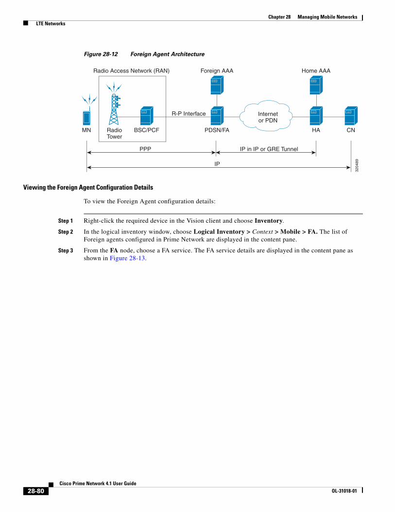
Chapter 28 Managing Mobile Networks LTE Networks
Figure 28-12 Foreign Agent Architecture
Viewing the Foreign Agent Configuration Details
To view the Foreign Agent configuration details:
Step 1 Right-click the required device in the Vision client and choose Inventory.
Step 2 In the logical inventory window, choose Logical Inventory > Context > Mobile > FA. The list of Foreign agents configured in Prime Network are displayed in the content pane.
Step 3 From the FA node, choose a FA service. The FA service details are displayed in the content pane as shown in Figure 28-13.
RadioTower
Radio Access Network (RAN)
BSC/PCFMN
3204
89
PDSN/FA
PPP
Foreign AAA
R-P Interface
HA CN
Home AAA
Internetor PDN
IP in IP or GRE Tunnel
IP
28-80Cisco Prime Network 4.1 User Guide
OL-31018-01

Chapter 28 Managing Mobile Networks LTE Networks
Figure 28-13 Foreign Agent Service Details
Table 28-55 displays the Foreign Agent configuration details.
28-81Cisco Prime Network 4.1 User Guide
OL-31018-01

Chapter 28 Managing Mobile Networks LTE Networks
Table 28-55 FA Configuration Details
Field Description
Service Name The unique name to identify the FA service.
Status The status of the FA service, which can be any one of the following:
• Down
• Running
• Initiated
• Unknown
This field defaults to Down.
Bind Address The IPv4 address to which the service is bound.
Local IP Port The UDP port for the R-P Interface of the IP socket. This port can be any value between 1 and 65535, and defaults to 434.
Max. Subscribers The maximum subscriber sessions that is supported by the service. This can be any value between 0 and 2500000, and defaults to 2500000.
Default Subscriber The name of the subscriber template that is applicable to the subscribers using this domain alias.
A11 Signalling Packets IP Header DSCP
The Differential Service Code Point (DSCP) value in the IP header. This value can range between 0x0 and 0x3F, and defaults to 0x0F.
Note The Differentiated Services (DS) field of a packet contains 6 bits that represents the DSCP value. Out of these 6 bits, five of them represent the DSCP. Hence, you can assign upto 32 DSCPs for various priorities.
Registration Life Time The amount of time (in seconds) that an A10 connection can exist before its registration expires. This time can be any value between 1 and 65534, and defaults to 1800 seconds.
New Call Policy The call policy for one or all the services, which can be any one of the following:
• Reject
• None
This field defaults to None.
Challenge Window The number of challenges that can be handled by the FA.
Dynamic MIP Key Update
The status of the Dynamic Mobile IP Key update feature. This option is disabled by default.
Ignore Stale Challenge The status of the Ignore Stale Challenge in MIP RRQ. This option is disabled by default.
Ignore MIP Key Data The status of the Ignore MIP Key data. This option is disabled by default.
Allow Private Address Without Reverse Tunnel
Indicates whether the mobile node can use reverse tunnel for a private address. This option is disabled by default.
Registration Timeout The amount of time (in seconds) for the registration reply timeout.
28-82Cisco Prime Network 4.1 User Guide
OL-31018-01
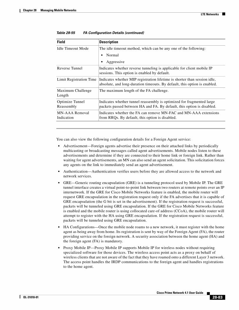
Chapter 28 Managing Mobile Networks LTE Networks
You can also view the following configuration details for a Foreign Agent service:
• Advertisement—Foreign agents advertise their presence on their attached links by periodically multicasting or broadcasting messages called agent advertisements. Mobile nodes listen to these advertisements and determine if they are connected to their home link or foreign link. Rather than waiting for agent advertisements, an MN can also send an agent solicitation. This solicitation forces any agents on the link to immediately send an agent advertisement.
• Authentication—Authentication verifies users before they are allowed access to the network and network services.
• GRE—Generic routing encapsulation (GRE) is a tunneling protocol used by Mobile IP. The GRE tunnel interface creates a virtual point-to-point link between two routers at remote points over an IP internetwork. If the GRE for Cisco Mobile Networks feature is enabled, the mobile router will request GRE encapsulation in the registration request only if the FA advertises that it is capable of GRE encapsulation (the G bit is set in the advertisement). If the registration request is successful, packets will be tunneled using GRE encapsulation. If the GRE for Cisco Mobile Networks feature is enabled and the mobile router is using collocated care-of address (CCoA), the mobile router will attempt to register with the HA using GRE encapsulation. If the registration request is successful, packets will be tunneled using GRE encapsulation.
• HA Configurations—Once the mobile node roams to a new network, it must register with the home agent as being away from home. Its registration is sent by way of the Foreign Agent (FA), the router providing service on the foreign network. A security association between the home agent (HA) and the foreign agent (FA) is mandatory.
• Proxy Mobile IP—Proxy Mobile IP supports Mobile IP for wireless nodes without requiring specialized software for those devices. The wireless access point acts as a proxy on behalf of wireless clients that are not aware of the fact that they have roamed onto a different Layer 3 network. The access point handles the IRDP communications to the foreign agent and handles registrations to the home agent.
Idle Timeout Mode The idle timeout method, which can be any one of the following:
• Normal
• Aggressive
Reverse Tunnel Indicates whether reverse tunneling is applicable for client mobile IP sessions. This option is enabled by default.
Limit Registration Time Indicates whether MIP registration lifetime is shorter than session idle, absolute, and long-duration timeouts. By default, this option is enabled.
Maximum Challenge Length
The maximum length of the FA challenge.
Optimize Tunnel Reassembly
Indicates whether tunnel reassembly is optimized for fragmented large packets passed between HA and FA. By default, this option is disabled.
MN-AAA Removal Indication
Indicates whether the FA can remove MN-FAC and MN-AAA extensions from RRQs. By default, this option is disabled.
Table 28-55 FA Configuration Details (continued)
Field Description
28-83Cisco Prime Network 4.1 User Guide
OL-31018-01

Chapter 28 Managing Mobile Networks LTE Networks
• Registration Revocation—Registration Revocation is a method by which a mobility agent (one that provides Mobile IP services to a mobile node) can notify the other mobility agent of the termination of a registration due to administrative reasons or MIP handoff. When a mobile changes its point of attachment (FA), or needs to terminate the session administratively, the HA sends a registration revocation message to the old FA. The old FA tears down the session and sends a registration revocation acknowledgement message to the HA. Additionally, if the PDSN/FA needs to terminate the session administratively, the FA sends a registration revocation message to the HA. The HA deletes the binding for the mobile, and sends a registration revocation acknowledgement to FA.
Viewing the Advertisement Configuration Details
To view the Advertisement configuration details for a foreign agent:
Step 1 Right-click the required device in the Vision client and choose Inventory.
Step 2 In the logical inventory window, choose Logical Inventory > Context > Mobile > FA > FA service > Advertisement. The details are displayed in the content pane.
Table 28-56 displays the Advertisement configuration details.
Viewing the Authentication Configuration Details
To view the Authentication configuration details for a foreign agent:
Step 1 Right-click the required device in the Vision client and choose Inventory.
Step 2 In the logical inventory window, choose Logical Inventory > Context > Mobile > FA > FA service > Authentication. The details are displayed in the content pane.
Table 28-57 displays the Authentication configuration details.
Table 28-56 Advertisement Configuration Details
Field Description
Advertisement Delay The time delay (in milliseconds) for the first advertisement for a WiMax call. This time can be any value between 10 and 5000, and defaults to 1000.
Advertisement Interval The advertisement interval time (in milliseconds). This time can be any value between 100 and 1800000, and defaults to 5000 milliseconds.
Advertisement Life Time
The maximum registration life time (in seconds) of the advertisement. This time can be any value between 1 and 65535, and defaults to 600 seconds.
Number of Advertisements Sent
The number of initial agent advertisements sent. This number can be any value between 1 and 65535, and defaults to 5.
Prefix Length Extension Indicates whether the service address of the FA must be included in the Router Address field of the agent advertisement. If this field is set to Yes, then a prefix-length extension is appended to the router address field. By default, this option is set to No.
28-84Cisco Prime Network 4.1 User Guide
OL-31018-01
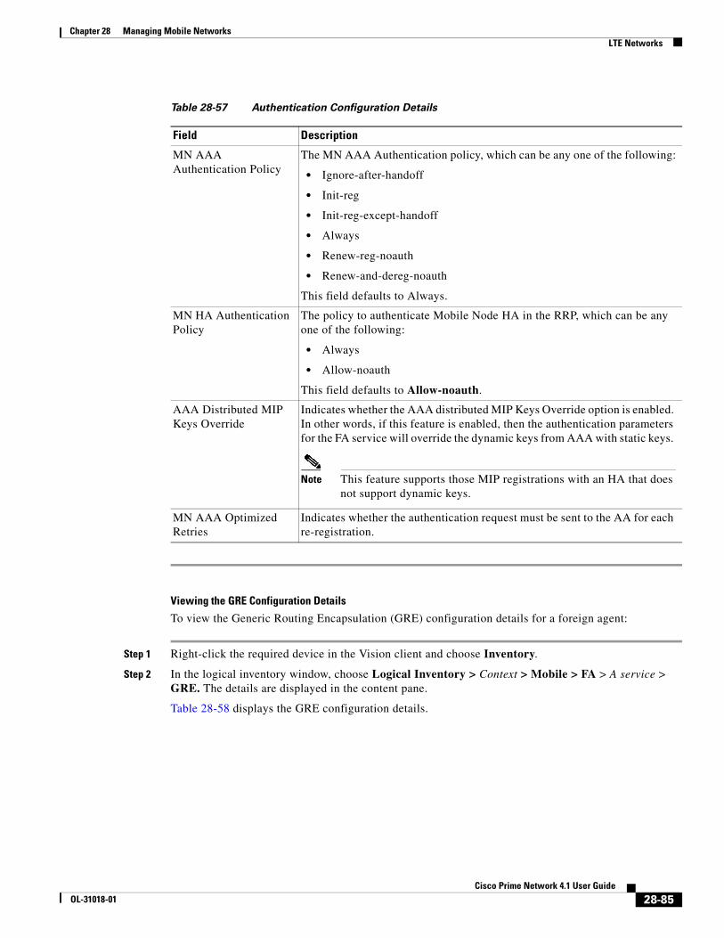
Chapter 28 Managing Mobile Networks LTE Networks
Viewing the GRE Configuration Details
To view the Generic Routing Encapsulation (GRE) configuration details for a foreign agent:
Step 1 Right-click the required device in the Vision client and choose Inventory.
Step 2 In the logical inventory window, choose Logical Inventory > Context > Mobile > FA > A service > GRE. The details are displayed in the content pane.
Table 28-58 displays the GRE configuration details.
Table 28-57 Authentication Configuration Details
Field Description
MN AAA Authentication Policy
The MN AAA Authentication policy, which can be any one of the following:
• Ignore-after-handoff
• Init-reg
• Init-reg-except-handoff
• Always
• Renew-reg-noauth
• Renew-and-dereg-noauth
This field defaults to Always.
MN HA Authentication Policy
The policy to authenticate Mobile Node HA in the RRP, which can be any one of the following:
• Always
• Allow-noauth
This field defaults to Allow-noauth.
AAA Distributed MIP Keys Override
Indicates whether the AAA distributed MIP Keys Override option is enabled. In other words, if this feature is enabled, then the authentication parameters for the FA service will override the dynamic keys from AAA with static keys.
Note This feature supports those MIP registrations with an HA that does not support dynamic keys.
MN AAA Optimized Retries
Indicates whether the authentication request must be sent to the AA for each re-registration.
28-85Cisco Prime Network 4.1 User Guide
OL-31018-01
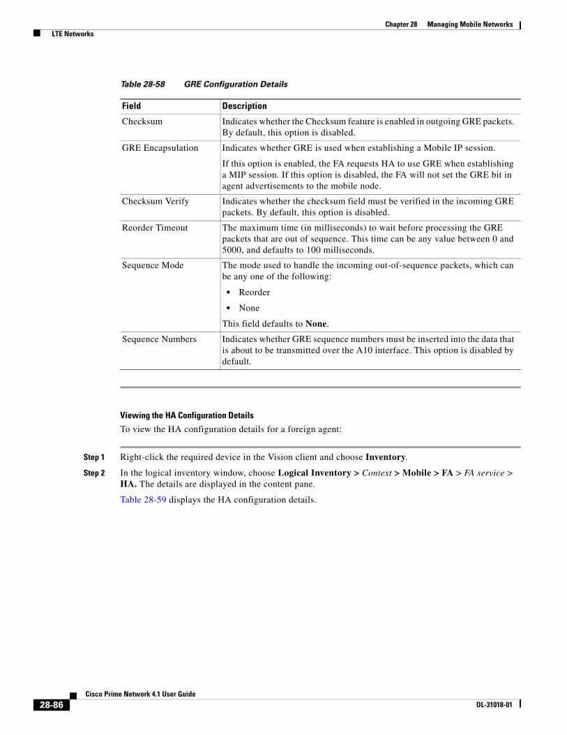
Chapter 28 Managing Mobile Networks LTE Networks
Viewing the HA Configuration Details
To view the HA configuration details for a foreign agent:
Step 1 Right-click the required device in the Vision client and choose Inventory.
Step 2 In the logical inventory window, choose Logical Inventory > Context > Mobile > FA > FA service > HA. The details are displayed in the content pane.
Table 28-59 displays the HA configuration details.
Table 28-58 GRE Configuration Details
Field Description
Checksum Indicates whether the Checksum feature is enabled in outgoing GRE packets. By default, this option is disabled.
GRE Encapsulation Indicates whether GRE is used when establishing a Mobile IP session.
If this option is enabled, the FA requests HA to use GRE when establishing a MIP session. If this option is disabled, the FA will not set the GRE bit in agent advertisements to the mobile node.
Checksum Verify Indicates whether the checksum field must be verified in the incoming GRE packets. By default, this option is disabled.
Reorder Timeout The maximum time (in milliseconds) to wait before processing the GRE packets that are out of sequence. This time can be any value between 0 and 5000, and defaults to 100 milliseconds.
Sequence Mode The mode used to handle the incoming out-of-sequence packets, which can be any one of the following:
• Reorder
• None
This field defaults to None.
Sequence Numbers Indicates whether GRE sequence numbers must be inserted into the data that is about to be transmitted over the A10 interface. This option is disabled by default.
28-86Cisco Prime Network 4.1 User Guide
OL-31018-01

Chapter 28 Managing Mobile Networks LTE Networks
Table 28-59 HA Configuration Details
Field Description
HA Monitoring The HA monitoring status of the FA. This option is disabled by default.
AAA-HA Override Indicates whether AAA HA can override Mobile Node during call establishment for HA assignment.
Dynamic HAFailover Indicates whether failover during call establishment for Home Agent assignment is allowed.
HA Monitor Interval The time interval (in seconds) to send HA monitoring requests. This time can be any value between 1 and 36000, and defaults to 30 seconds.
HA Monitor Maximum Inactivity Time
The maximum amount of time (in seconds) when there is no MIP traffic between FA and HA, which triggers the HA monitoring feature. This time can be any value between 30 and 600, and defaults to 60 seconds.
HA Monitor Retry Count
The number of times HA monitoring requests are sent before deciding that the HA is not reachable. This count can be any value between 0 and 10, and defaults to 5.
FA SPI List Name The name of the SPI list linked with the FA service and configured for the selected context. Clicking on this link will take you to the relevant list under the SPI node.
IKE
Peer HA Address The IP address of the peer home agent.
Crypto Map Name The IKE crypto map for the peer home agent.
SPI
SPI Number The unique SPI number that indicates a security context between the services. This number can be any value between 256 and 4294967295.
Remote Address The IP address of the source service, which is expressed either in the IPv4 dotted decimal notation or IPv6 colon separated notation.
Hash Algorithm The hash algorithm used between the source and destination services.
Time Stamp Tolerance The acceptable time difference (in seconds) in timestamps, which can be any value between 0 and 65535.
Note If the actual timestamp difference exceeds the value here, then the session is rejected. If this value is 0, then the timestamp tolerance checking is disabled at the receiving end.
Replay Protection The replay protection scheme that is implemented by the service.
Description The description of the SPI.
Net Mask The net mask for the IP address of the SPI. This field defaults to 255.255.255.255.
HA Monitor Indicates whether HA monitoring is enabled.
28-87Cisco Prime Network 4.1 User Guide
OL-31018-01

Chapter 28 Managing Mobile Networks LTE Networks
Viewing the Proxy Mobile IP Configuration Details
To view the Proxy Mobile IP configuration details for a foreign agent:
Step 1 Right-click the required device in the Vision client and choose Inventory.
Step 2 In the logical inventory window, choose Logical Inventory > Context > Mobile > FA > FA service > Proxy Mobile IP. The details are displayed in the content pane.
Table 28-60 displays the Proxy Mobile IP configuration details.
Viewing the Registration Revocation Configuration Details
To view the Registration Revocation configuration details for a foreign agent:
Step 1 Right-click the required device in the Vision client and choose Inventory.
Step 2 In the logical inventory window, choose Logical Inventory > Context > Mobile > FA > FA service > Registration Revocation. The details are displayed in the content pane.
Table 28-61 displays the Registration Revocation configuration details.
Table 28-60 Proxy Mobile IP Configuration Details
Field Description
Proxy MIP Indicates the status of the Proxy Mobile IP.
Encapsulation Type The data encapsulation type to be used in PMIP call for specific FA services, which can be any one of the following:
• IPIP
• GRE
This field defaults to IPIP.
HA Failover The failover status of the FA. This option is disabled by default.
HA Failover Max Attempts
The maximum number of times for HA Failover. This can be any value between 1 and 10, and defaults to 4.
HA Failover Timeout The timeout (in seconds) for the HA failover. This time can be any value between 1 and 50, and defaults to 2.
HA Failover Attempts Before Switching
The number of times HA Failover was attempted, before switching over to an alternate HA. This can be any value between 1 and 5, and defaults to 2.
HA Failover Reply Code Trigger
The action to be taken on receipt of the configured reject code.
Max Retransmissions The maximum number of times the FA is allowed to retransmit Proxy Mobile IP registration requests to the HA. This number can be any value between 1 and 4294967295, and defaults to 5.
Retransmission Timeout
The retransmission timeout (in seconds) for Proxy Mobile IP messages on event of failover. This time can be any value between 1 and 100, and defaults to 3.
Renew Time The percentage of lifetime at which point the renewal is sent. This percent can be between 0 and 100, and defaults to 75.
28-88Cisco Prime Network 4.1 User Guide
OL-31018-01

Chapter 28 Managing Mobile Networks LTE Networks
Configuration Commands for Foreign Agent
To enable Mobile IP services on your network, you must determine which home agents will facilitate the tunneling for selected IP address, and where these devices or router will be allowed to roam. The areas, or subnets, into which the hosts are allowed to roam determine where foreign agent services need to be set up.
Use the following commands to manage foreign agents. These commands can be launched from the logical inventory by choosing the Context > Commands > Configuration or Context > Commands > Show. Your permissions determine whether you can run these commands (see ). To find out if a device supports these commands, see the Cisco Prime Network 4.0 Supported Cisco VNEs.
Table 28-61 Registration Revocation Configuration Details
Field Description
Registration Revocation State
Indicates the status of the registration revocation. If this feature is enabled, then the FA can send a revocation message to the HA when revocation is negotiated with the HA and MIP binding is terminated. This feature is disabled by default.
Revocation IBit The status of the Ibit on the registration revocation. If this feature is enabled, the FA can negotiate the Ibit via PRQ/RRP messages and process the Ibit revocation messages. This feature is disabled by default.
Internal Failure Indicates whether a revocation message must be sent to the HA for those sessions that are affected by internal task failure.
Revocation Maximum Retries
The maximum number times a revocation message must be retransmitted before failure. This value can be any value between 0 and 10, and defaults to 3.
Revocation Timeout The time period (in seconds) to wait for an acknowledgement from the HA before the revocation message is retransmitted. This time can be any value between 1 and 10, and defaults to 3.
Table 28-62 Foreign Agent Configuration Commands
Command Navigation Description
Create FA Right-click on a context > Commands > Configuration
Use this command to create a new foreign agent service for the selected context.
Modify FA
Delete FA
Expand FA node > Right-click FA service > Commands > Configuration
Use these commands to modify/delete an existing foreign agent service configured for the selected context.
Show FA Expand FA node > Right-click FA service > Commands > Show
Use this command to view and confirm the foreign agent configuration details.
Create SPI Expand FA node > Right-click FA service > Commands > Configuration
Use this command to configure Security Parameter Index (SPI) for a foreign agent service.
28-89Cisco Prime Network 4.1 User Guide
OL-31018-01

Chapter 28 Managing Mobile Networks LTE Networks
Monitoring Evolved Packet Data Gateway (ePDG)
In today’s market, there are multiple access networks for mobile technologies. For example, the following access networks are available for 3rd Generation Partnership Project (3GPP) network:
• General Packet Radio Service (GPRS). See GPRS/UMTS Networks, page 28-1.
Modify SPI
Delete SPI
Expand FA node > Expand FA service node > HA Configuration > Right-click on SPI Number in content pane > Commands > Configuration
Use these commands to modify and delete an existing SPI configured for a foreign agent service.
Create IKE Expand FA node > Right-click FA service > Commands > Configuration
Use this command to configure Internet Key Exchange (IKE) for a foreign agent service. If foreign agent reverse tunneling creates a tunnel that transverses a firewall, any mobile node that knows the addresses of the tunnel endpoints can insert packets into the tunnel from anywhere in the network. It is recommended to configure Internet Key Exchange (IKE) or IP Security (IPSec) to prevent this.
Modify IKE
Delete IKE
Expand FA node > Expand FA service node > HA Configuration > right-click on IKE Number in content pane > Commands > Configuration
Use these commands to modify and delete an existing IKE configured for a foreign agent service.
Modify Advertisement
Expand FA node > FA service > right-click Advertisement > Commands > Configuration
Use this command to modify the advertisement configuration settings specified for a foreign agent.
Modify Authentication
Expand FA node > FA service > right-click Authentication > Commands > Configuration
Use this command to modify the authentication configuration settings specified for a foreign agent.
Modify GRE Expand FA node > FA service > right-click GRE > Commands > Configuration
Use this command to modify the Generic Routing Encapsulation (GRE) configuration settings specified for a foreign agent.
Modify HA Configuration
Expand FA node > FA service > right-click HA Configuration > Commands > Configuration
Use this command to modify the Home Agent configuration settings specified for a foreign agent.
Modify Proxy Mobile IP
Expand FA node > FA service > right-click Proxy Mobile IP > Commands > Configuration
Use this command to modify the Proxy Mobile IP configuration settings specified for a foreign agent.
Modify Registration Revocation
Expand FA node > FA service > right-click Registration Revocation > Commands > Configuration
Use this command to modify the Registration revocation configuration settings specified for a foreign agent.
Table 28-62 Foreign Agent Configuration Commands (continued)
Command Navigation Description
28-90Cisco Prime Network 4.1 User Guide
OL-31018-01

Chapter 28 Managing Mobile Networks LTE Networks
• Global System for Mobile communication (GSM)
• Universal Mobile Telecommunication System (UMTS). See GPRS/UMTS Networks, page 28-1.
The following access network are available for Non-3GPP network:
• Worldwide Interoperability for Microwave Access (WiMAX)
• CDMA2000
• Wireless local area network (WLAN)
• Fixed networks
The Non-3GPP networks can be categorized into two—Trusted and Untrusted. While the trusted non-3GPP networks can interact directly with the Evolved Packet Core (EPC), the untrusted networks are required to pass through a security gateway to gain access to the EPC. This security gateway is called the Evolved Packet Data Gateway or ePDG.
When a user transmits data to the EPC using an untrusted non-3GPP network access, the ePDG must act as a termination node of IPSec tunnels established with the user equipment and secure the data being sent. Figure 28-14 shows the ePDG architecture.
Figure 28-14 ePDG Architecture
IP Security (IPSec)
Internet Protocol Security or IPSec is a protocol suite that interacts with one another to provide secure private communications across IP networks. These protocols allow the system to establish and maintain secure tunnels with peer security gateways. In accordance with the following standards, IPSec provides a mechanism for establishing secure channels from mobile subscribers to pre-defined end points (such as enterprise or home networks):
• RFC 2401, Security Architecture for the Internet Protocol
• RFC 2402, IP Authentication Header (AH)
eNodeB
Signaling Interface
Bearer Interface
S1-U S5
S2b
SGi
S1-MMES11MME
3204
96
S6a
Gx
S2a
Gxc
HSS
OFCS
SWx
SWm
SWu
AAA
E-UTRAN Operator’sIP Services
Untrusted non-3GPPIP Access
wPDG
S-GW P-GW
PCRF
Trusted non-3GPPIP Access
28-91Cisco Prime Network 4.1 User Guide
OL-31018-01

Chapter 28 Managing Mobile Networks LTE Networks
• RFC 2406, IP Encapsulating Security Payload (ESP)
• RFC 2409, The Internet Key Exchange (IKE)
• RFC-3193, Securing L2TP using IPSEC, November 2001
IPSec can be implemented for the following applications:
• PDN Access: Subscriber IP traffic is routed over an IPSec tunnel from the system to a secure gateway on the packet data network (PDN) as determined by access control list (ACL) criteria.
• Mobile IP: Mobile IP control signals and subscriber data is encapsulated in IPSec tunnels that are established between foreign agents (FAs) and home agents (HAs) over the Pi interfaces.
IKEv2 and IPSec Encryption
ePDG supports Internet Key Exchange Version 2 (IKEv2) and IP Security Encapsulating Security Payload (IPSec ESP) encryption over IPv4 transport. The IKEv2 and IPSec encryption takes care of network domain security for all IP packet switched networks. It uses cryptographic techniques to ensure ensures confidentiality, integrity, authentication, and anti-replay protection.
ePDG Security
In Prime Network, the following security services are available for ePDG:
• Crypto template—Used to define the IKEv2 and IPSec policies. In other words, it includes IKEv2 and IPSec parameters for keepalive, lifetime, NAT-T and cryptographic and authentication algorithms.
• EAP Profile—Defines the EAP authentication method and associated parameters.
• Transform Set—Define the negotiable algorithms for IKE SAs (Security Associations) and Child SAs to enable calls to connect to the ePDG.
Viewing the Crypto Template Service Details
To view the Crypto template details:
Step 1 Right-click the required device in the Vision client and choose Inventory.
Step 2 In the logical inventory window, choose Logical Inventory > Context > Security Association > Crypto Template. The list of crypto templates are displayed in the content pane.
Step 3 In the Crypto Template node, choose the crypto template. The template details are displayed in the content pane. Figure 28-15 displays the crytpo template details.
28-92Cisco Prime Network 4.1 User Guide
OL-31018-01

Chapter 28 Managing Mobile Networks LTE Networks
Figure 28-15 Crypto Template Details
Table 28-63 displays the Crypto template details.
Table 28-63 Crypto Template Details
Field Description
Template Name The unique name of the template.
Control Don’t Fragment The Don’t Fragment (DF) bit in the IPSec tunnel data packet, which is encapsulated in the IPSec headers at both ends. The values for this field are:
• clear-bit—Clear DF Bit
• copy-bit—Copy DF bit from inner header
• set-bit—Set DF Bit
This field defaults to copy-bit.
Cookie Challenge-Detect DOS Attack
The cookie challenge parameters for the crypto template, which is used to prevent malicious Denial of Service (DOS) attacks against the server.
Note This feature prevents DOS attacks by sending a challenge cookie. If the response from the sender does not incorporate the expected cookie data, the packets are dropped.
28-93Cisco Prime Network 4.1 User Guide
OL-31018-01

Chapter 28 Managing Mobile Networks LTE Networks
Notify Payload - Half Open Session Start
The initial count of the number of half-open sessions per IPSec manager. Transmission of information will start only when the number of half-open sessions currently open exceed the starting count.
Note A session is considered half open if a Packet Data Interworking Function (PDIF) has responded to an IKEv2 INIT request with an IKEv2 INIT response, but no further messages were received on the particular IKE SA.
Notify Payload - Half Open Session End
The maximum count of half open sessions per IPSec manager. Transmission of information will stop when the number of half-open sessions currently open is less than this count.
Authentication Local The local gateway key used for authentication.
Authentication Remote The remote gateway key used for authentication.
Keepalive Interval The period of time (in seconds) that must elapse before the next keepalive request is sent.
Keepalive Retries The period of time (in seconds) that must elapse before the keepalive request is resent.
Keepalive Timeout The keepalive time (in terms of seconds) for dead peer detection.
Maxchild SA Count The maximum number of child SA per IKEv2 policy, which can be any value between 1 and 4.
Maxchild SA Overload Action
The action to be taken when the specified soft limit for the maximum number of SA is reached, which can be any one of the following:
Ignore—The IKEv2 stack ignores the specified soft limit for the SA and allows new SA to be created.
Terminate—The IKEv2 stack does not allow new child SA to be created when the specified soft limit is reached.
NAI CustomIDr The unique user specified identification number to be used in the crypto template for Network Access Identifier (NAI).
Crypto Template Payloads
Payload Instance The payload instance configured for the crypto template.
Payload Name The unique name of the crypto template payload.
Ignore Rekeying Requests
Indicates whether IKESA rekeying requests must be ignored.
IP Address Allocation The IP Address Allocation scheme configured for the crypto template payload.
Lifetime The lifetime (in seconds) for the IPSec Child Security Associations derived from the crypto template.
Lifetime (KB) The lifetime (in kilo bytes) for the IPSec Child Security Associations derived from the crypto template.
Maximum Child SA The maximum number of IPSec Child Security Associations (SA) that may be derived from a single IKEv2 IKE SA.
Table 28-63 Crypto Template Details (continued)
Field Description
28-94Cisco Prime Network 4.1 User Guide
OL-31018-01

Chapter 28 Managing Mobile Networks LTE Networks
Viewing the EAP Profile Details
To view the EAP Profile details:
Rekey Indicates whether IPSec Child Security Association rekeying must be enabled, after approximately 90% of the child SA lifetime has expired.
Rekey Keepalive Indicates whether rekeying must be allowed if data is not received on the security association since the last rekey.
TSI Start Address The IKEv2 Initiator Traffic Selector payload start address configured for the crypto template.
TSI End Address The IKEv2 Initiator Traffic Selector payload end address configured for the crypto template.
TSR Start Address The IKEv2 Responder Traffic Selector payload start address.
TSR End Address The IKEv2 Responder Traffic Selector payload end address.
Crypto Template IKESAs
IKESA Instance The IKESA instance configured for the crypto template.
Allow Empty IKESA Indicates whether empty IKESA is allowed. By default, empty IKESA is not allowed.
Certificate Sign The certificate sign to be used. This field defaults to pkcs1.5.
Ignore Notify Protocol ID
Indicates whether the IKEv2 Exchange Notify Payload Protocol-ID values must be ignored for strict RFCA 4306 compliance.
Ignore Rekeying Requests
Indicates whether IKESA rekeying requests must be ignored.
Keepalive User Activity Indicates whether the user inactivity timer must be reset when keepalive messages are received from the peer.
Max Retransmission The maximum number of retransmissions of an IKEv2 IKE exchange request that is allowed if a response is not received.
Policy Congestion Rejection Notify Status
Indicates whether an error notification message must be sent in response to an IKE_SA INIT exchange, when IKESA sessions cannot be established anymore.
Policy Error Notification Indicates whether an error notification message must be sent for invalid IKEv2 exchange message ID and syntax.
Rekey Indicates whether IKESA rekeying must occur before the configured lifetime expires (which is approximately at 90% of the lifetime interval). By default, rekeying is not allowed.
Retransmission Timeout The time period (in milliseconds) that must elapse before a retransmission of an IKEv2 IKE exchange request is sent when a corresponding response is not received.
Setup Timer The number of seconds before a IKEv2 security association, which is not fully established, is terminated.
Table 28-63 Crypto Template Details (continued)
Field Description
28-95Cisco Prime Network 4.1 User Guide
OL-31018-01
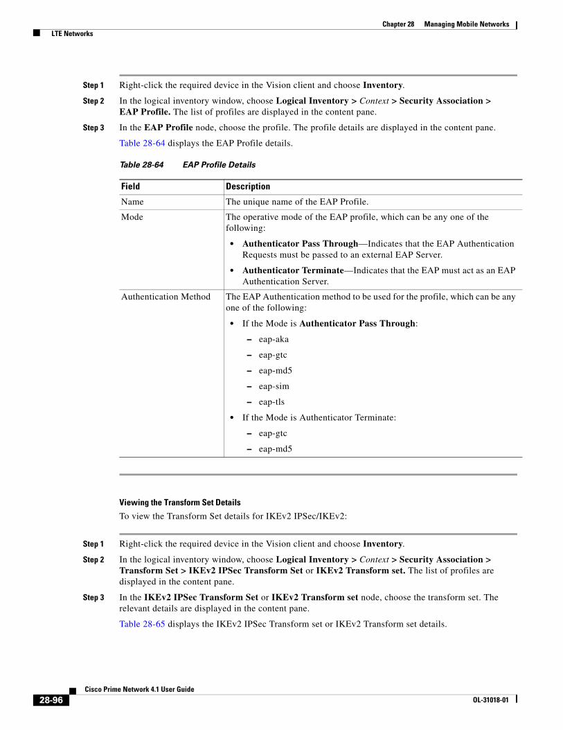
Chapter 28 Managing Mobile Networks LTE Networks
Step 1 Right-click the required device in the Vision client and choose Inventory.
Step 2 In the logical inventory window, choose Logical Inventory > Context > Security Association > EAP Profile. The list of profiles are displayed in the content pane.
Step 3 In the EAP Profile node, choose the profile. The profile details are displayed in the content pane.
Table 28-64 displays the EAP Profile details.
Viewing the Transform Set Details
To view the Transform Set details for IKEv2 IPSec/IKEv2:
Step 1 Right-click the required device in the Vision client and choose Inventory.
Step 2 In the logical inventory window, choose Logical Inventory > Context > Security Association > Transform Set > IKEv2 IPSec Transform Set or IKEv2 Transform set. The list of profiles are displayed in the content pane.
Step 3 In the IKEv2 IPSec Transform Set or IKEv2 Transform set node, choose the transform set. The relevant details are displayed in the content pane.
Table 28-65 displays the IKEv2 IPSec Transform set or IKEv2 Transform set details.
Table 28-64 EAP Profile Details
Field Description
Name The unique name of the EAP Profile.
Mode The operative mode of the EAP profile, which can be any one of the following:
• Authenticator Pass Through—Indicates that the EAP Authentication Requests must be passed to an external EAP Server.
• Authenticator Terminate—Indicates that the EAP must act as an EAP Authentication Server.
Authentication Method The EAP Authentication method to be used for the profile, which can be any one of the following:
• If the Mode is Authenticator Pass Through:
– eap-aka
– eap-gtc
– eap-md5
– eap-sim
– eap-tls
• If the Mode is Authenticator Terminate:
– eap-gtc
– eap-md5
28-96Cisco Prime Network 4.1 User Guide
OL-31018-01

Chapter 28 Managing Mobile Networks LTE Networks
Table 28-65 IKEv2 IPSec Transform Set/IKEv2 Transform set Details
Field Description
Name The name of the transform set.
DH Group The Diffie-Hellman (DH) group for the transform set, which can be any one of the following:
• 1—Configure Diffie-Hellman Group 1:768-bit MODP Group
• 14—Configure Diffie-Hellman Group 14:2048-bit MODP Group
• 2—Configure Diffie-Hellman Group 2:1024-bit MODP Group
• 5—Configure Diffie-Hellman Group 5:1536-bit MODP Group
This field defaults to 2—Configure Diffie-Hellman Group 2:1024-bit MODP Group.
Note The DH group is used to determine the length of the base Prime numbers used during the key exchange process in IKEv2. The cryptographic strength of any key derived, depends in part, on the strength of the DH group upon which the prime numbers are based.
Cipher The appropriate encryption algorithm and encryption key length for the IKEv2 IKE security association, which can be any one of the following:
• 3des-cbc
• aes-cbc-128
• aes-cbc-256
• des-cbc
• Null
This field defaults to AESCBC-128.
HMAC The Hash Message Authentication Code (HMAC) for the IKEv2 IPSec transform set,which can be any one of the following:
• aes-xcbc-96
• md5-96
• sha1-96
• sha2-256-128
• sha2-384-192
• sha2-512-256
This field defaults to sha1-96.
Note HMAC is a type of message authentication code calculated using a cryptographic hash function in combination with a secret key to verify both data integrity and message authenticity. A hash takes a message of any size and transforms it into a message of fixed size (the authenticator value), which is truncated and transmitted.
28-97Cisco Prime Network 4.1 User Guide
OL-31018-01

Chapter 28 Managing Mobile Networks LTE Networks
Viewing the ePDG Configuration Details
To view the ePDG configuration details:
Step 1 Right-click the required device in the Vision client and choose Inventory.
Step 2 In the logical inventory window, choose Logical Inventory > Context > Mobile > EPDG. The list of EPDG services configured in Prime Network are displayed in the content pane.
Step 3 From the EPDG node, choose an EPDG service. The EPDG service details are displayed in the content pane.
Table 28-66 displays the EPDG service details.
Mode The encapsulation mode for the transform set, which can be any one of the following:
• transport
• tunnel
PRF The Pseudo-random Function (PRF) for the transform set, which can be any one of the following:
• aes-xcbc-128
• md5
• sha1
• sha2-256
• sha2-384
• sha2-512
This field defaults to SHA1. This field is applicable only for IKEv2 transform sets.
Note This function is used to generate keying material for all cryptographic algorithms. It produces a string of bits that cannot be distinguished from random bit strings without the secret key.
Life Time The time period for which the secret keys used for various aspects of a configuration is valid (before it times out). This field is applicable only for IKEv2 transform sets.
Table 28-65 IKEv2 IPSec Transform Set/IKEv2 Transform set Details
Field Description
28-98Cisco Prime Network 4.1 User Guide
OL-31018-01

Chapter 28 Managing Mobile Networks LTE Networks
Table 28-66 EPDG Service Details
Field Description
Service Name The unique name of the ePDG service.
Status The status of the ePDG service, which can be any one of the following:
• Initiated
• Running
• Down
• Started
• Nonstarted
IP Address The IPV4 address of the ePDG service.
UDP Port The User Datagram Protocol (UDP) port of the ePDG service.
Crypto Template The name of the IKEv2 crypto template to be used by the ePDG service. This template is used to define the cryptographic policy for the ePDG service.
Max Sessions The maximum number of sessions allowed for the ePDG service.
PLMN ID The unique identification code of the Public Land Mobile Network (PLMN) for the ePDG service. This id is made up of the Mobile Country Code (MCC) and the Mobile Network Code (MNC).
MAG Service Context The name of the context where the Mobile Access Gateway (MAG) services are configured. If a MAG service is not configured for the ePDG service, then one of the MAG services defined in the context is selected.
MAG Service The name of the MAG service that handles the mobile IPv6 sessions.
Setup Timeout The maximum time (in seconds) allowed for the session setup.
DNS PGWClient Context
The name of the context where the Domain Name System (DNS) client is configured for the Packet Data Network Gateway (PWG) selection.
DNS PGW Selection The criteria to select a PGW service from the DNS. This criteria is based on the topology and/or weight from the DNS.
FQDN The Fully Qualified Domain Name (FQDN), which is used for longest suffix match during dynamic allocation.
PGW Selection Agent Info Error Action
The action to be taken when the expected MIP6 agent information is not received from Authentication, Authorization, and Accounting (AAA) or Hosting Solution Software (HSS).
User Name MAC Address Stripping
Indicates whether the MAC address in the username obtained from the user equipment must be stripped.
User Name MAC Address Validation
Indicates whether the MAC address in the username obtained from the user equipment must be validated.
User Name MAC Address Validation Failure Action
Indicates the action that must be taken on failure of the validation of the MAC address in the user name obtained from the user equipment.
New Call Policy Indicates the busy-out policy that must be followed to reject the incoming calls from individual users.
28-99Cisco Prime Network 4.1 User Guide
OL-31018-01

Chapter 28 Managing Mobile Networks LTE Networks
Configuration Commands for ePDG
The following ePDG commands can be launched from the logical inventory by choosing the Context > Commands > Configuration or Context > Commands > Show. Your permissions determine whether you can run these commands (see ). To find out if a device supports these commands, see the Cisco Prime Network 4.0 Supported Cisco VNEs.
Monitoring Packet Data Serving Node (PDSN)
Packet Data Serving Node, or PDSN, is a component of the Code Division Multiple Access (CDMA) 2000 mobile network. It acts as a connection point between the Radio Access Network (RAN) and IP Network. PDSN also manages PPP sessions between the mobile provider’s core IP network and the mobile node.
In other words, it provides access to the Internet, intranets, and applications servers for mobile stations that utilize a CDMA2000 RAN. Acting as an access gateway, PDSN provides simple IP and mobile IP access, foreign agent support, and packet transport for virtual private networking. It acts as a client for Authentication, Authorization, and Accounting (AAA) servers and provides mobile stations with a gateway to the IP network.
PDSN Configurations
The following paragraphs list the different configurations for PDSN:
• Simple IP—In this protocol, the mobile user is assigned an IP address dynamically. The user can use this IP address within a defined geographical area, which is lost when the user moves out of the area. If the user moves out of the designated area, they must register with the service provider again to obtain a new IP address. Figure 28-16 depicts the working of this protocol.
Table 28-67 ePDG Configuration Commands
Command Navigation Description
Create ePDG Service
Right-click context > Commands > Configuration
Use this command to create a new ePDG service.
Modify ePDG Service
Expand EPDG Node > right-click EPDG service > Commands > Configuration
Use this command to modify the configuration details for an ePDG service.
Delete ePDG Service
Expand EPDG Node > right-click EPDG service > Commands > Configuration
Use this command to delete an ePDG service.
Show ePDG Service
Expand EPDG Node > right-click EPDG service > Commands > Show
Use this command to view and confirm the configuration details of an ePDG Service.
28-100Cisco Prime Network 4.1 User Guide
OL-31018-01
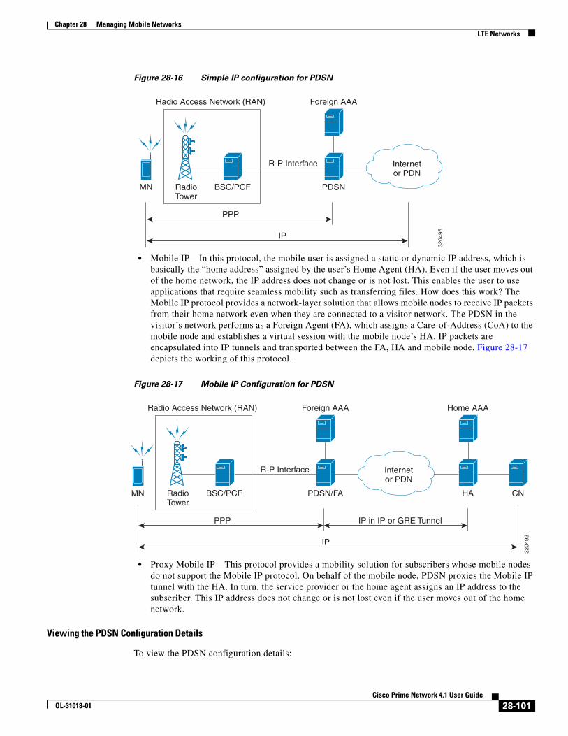
Chapter 28 Managing Mobile Networks LTE Networks
Figure 28-16 Simple IP configuration for PDSN
• Mobile IP—In this protocol, the mobile user is assigned a static or dynamic IP address, which is basically the “home address” assigned by the user’s Home Agent (HA). Even if the user moves out of the home network, the IP address does not change or is not lost. This enables the user to use applications that require seamless mobility such as transferring files. How does this work? The Mobile IP protocol provides a network-layer solution that allows mobile nodes to receive IP packets from their home network even when they are connected to a visitor network. The PDSN in the visitor’s network performs as a Foreign Agent (FA), which assigns a Care-of-Address (CoA) to the mobile node and establishes a virtual session with the mobile node’s HA. IP packets are encapsulated into IP tunnels and transported between the FA, HA and mobile node. Figure 28-17 depicts the working of this protocol.
Figure 28-17 Mobile IP Configuration for PDSN
• Proxy Mobile IP—This protocol provides a mobility solution for subscribers whose mobile nodes do not support the Mobile IP protocol. On behalf of the mobile node, PDSN proxies the Mobile IP tunnel with the HA. In turn, the service provider or the home agent assigns an IP address to the subscriber. This IP address does not change or is not lost even if the user moves out of the home network.
Viewing the PDSN Configuration Details
To view the PDSN configuration details:
RadioTower
Radio Access Network (RAN)
BSC/PCFMN
3204
95
PDSN
PPP
Foreign AAA
R-P Interface Internetor PDN
IP
RadioTower
Radio Access Network (RAN)
BSC/PCFMN
3204
92
PDSN/FA
PPP
Foreign AAA
R-P Interface
HA CN
Home AAA
Internetor PDN
IP in IP or GRE Tunnel
IP
28-101Cisco Prime Network 4.1 User Guide
OL-31018-01

Chapter 28 Managing Mobile Networks LTE Networks
Step 1 Right-click the required device in the Vision client and choose Inventory.
Step 2 In the logical inventory window, choose Logical Inventory > Context > Mobile > PDSN. The list of PDSN services configured in Prime Network are displayed in the content pane.
Step 3 From the PDSN node, choose a PDSN service. The PDSN service details are displayed in the content pane as shown in Figure 28-18.
Figure 28-18 PDSN Service Details
Table 28-68 displays the PDSN service details.
Table 28-68 PDSN Service Details
Field Description
Service Name The unique name of the PDSN service.
Status The status of the PDSN service, which can be any one of the following:
• Initiated
• Running
• Down
• Started
• Nonstarted
• Unknown
28-102Cisco Prime Network 4.1 User Guide
OL-31018-01

Chapter 28 Managing Mobile Networks LTE Networks
Bind Address The IP address to which the service is bound. This can be a IPv4 or IPv6 address.
Note Multiple IP addresses belonging to the same IP interface can be bound to different PDSN services, but one address can be bound to only one service.
Local IP Port The User Datagram Protocol (UDP) port for the R-P interface of the IP socket. This IP port can be any value between 1 and 65535 and defaults to 699.
Mobile IP The IP address of the Foreign agent that is configured for the PDSN service.
Simple IP Indicates whether the Simple IP configuration is available for the PDSN service, which can be any one of the following:
• Allowed
• Not Allowed (default value)
Max Subscribers The maximum number of subscribers that the PDSN service can support.
Registration Life Time The registration lifetime configured for all the subscribers to the service.
Max Retransmissions Maximum retries for transmitting RP control packets. This count can be any value between 1 and 1000000 and defaults to 5.
A11 Signalling Packets IP Header DSCP
The Differential Services Code Point (DSCP) value in the IP header.
NAI Construction Domain
The Network Access Identifier for the PDSN service. This field is made up of the Mobile Station Identifier (MSID) of the subscriber, a separator character and a domain name.
Note The domain name used here can be either the name supplied as part of the subscriber’s name or the domain alias.
Airlink Bad Sequence Number
The action to be taken when the PDSN receives an airlink record with a bad sequence number, which can be any one of the following:
• Accept (default value)
• Reject
Note At the time of the R-PA10 connection setup, an airlink record is assigned a unique sequence number.
Airlink Bad Sequence Number Deny Code
The reason for rejecting the airlink record with a bad sequence number, which can be any one of the following:
• Poorly Formed Request
• Unsupported Vendor ID
AAA 3GPP2 Service Option
The service options for which AAA 3GPP2 authentication is applicable.
Table 28-68 PDSN Service Details (continued)
Field Description
28-103Cisco Prime Network 4.1 User Guide
OL-31018-01

Chapter 28 Managing Mobile Networks LTE Networks
You can also view the following configuration details for a PDSN service:
• GRE
• IP Source Violation
• MSID
• PCF
• Policy
• PPP
• QoS
• Registrations
• Timers and Restrictions
Viewing the GRE Configuration Details
To view the Generic Routing Encapsulation (GRE) configuration details for a PDSN service:
Step 1 Right-click the required device in the Vision client and choose Inventory.
Step 2 In the logical inventory window, choose Logical Inventory > Context > Mobile > PDSN > PDSN service > GRE. The GRE details are displayed in the content pane.
Table 28-69 displays the GRE configuration details.
Service Option Entries
Service Option Number The service option numbers applicable for the PDSN service.
Note Each service option relates to a standard data service. Hence, these numbers determine the data services that are supported by the PDSN service.
Table 28-68 PDSN Service Details (continued)
Field Description
Table 28-69 GRE Configuration Details
Field Description
Checksum Indicates whether the Checksum field is applicable for outgoing GRE packets.By default, this option is disabled.
Checksum Verify Indicates whether the verification of the Checksum field is enabled for incoming GRE packets.
Reorder Time Out The maximum time (in milliseconds) for processing the GRE packets that are coming out of order. This time can be any value between 0 and 5000, and defaults to 100 milliseconds.
28-104Cisco Prime Network 4.1 User Guide
OL-31018-01

Chapter 28 Managing Mobile Networks LTE Networks
Viewing the IP Source Violation Details
A Source violation occurs when a mobile device sources packets to the PDSN with a IP address that is different from the one specified during setup. Using this feature, the packets that need not be sent over the network are dropped when it tries to pass through PDSN.
To view the IP Source Violation configuration details for a PDSN service:
Step 1 Right-click the required device in the Vision client and choose Inventory.
Sequence Mode The mode in which incoming out-of-sequence GRE packets are handled, which can be any one of the following:
• Reorder
• None
This field defaults to None.
Sequence Numbers Indicates whether GRE sequence numbers are inserted in data that is about to be transmitted over the A10 interface. By default, this option is disabled.
Flow Control Indicates whether flow control is supported by the selected PDSN service. If this option is enabled, PDSN sends flow control enabled Normal Vendor Specific Extensions (NSVE) in A11 RRPs. By default, this option is disabled.
Flow Control Time Out The amount of time (in milliseconds) to wait for an Transmitter On (XON) indicator from the RAN. This time can be any value between 1 and 1000000, and defaults to 1000 milliseconds.
Flow Control Action The action that must be taken when the timeout limit is reached, which can be any one of the following:
• disconnect-session
• resume-session.
Protocol Type The tunnel type for the GRE routing. This field defaults to Any.
Is 3GPP Ext Header QoS Marking
Indicates whether the 3GPP Extension Header QoS Marking is enabled for the selected PDSN feature.
Note If this feature is enabled and the PCF negotiation feature is enabled in A11 RRQ, then the PDSN will include QoS optional data attribute in the GRE 3GPP2 Extension Header.
IP Header DSCP Value The Differential Service Code Point (DSCP) value in the IP header that marks the GRE IP Header encapsulation. This can be any value between 0x0F and 0X3F, and defaults to 0X0F.
IP Header DSCP Value Packet Type
Indicates whether the IP Header DSCP Value packet type is specified for the packets. By default, this option is disabled.
GRE Segmentation Indicates whether segmentation of GRE packets is enabled. By default, this option is disabled.
Table 28-69 GRE Configuration Details (continued)
Field Description
28-105Cisco Prime Network 4.1 User Guide
OL-31018-01

Chapter 28 Managing Mobile Networks LTE Networks
Step 2 In the logical inventory window, choose Logical Inventory > Context > Mobile > PDSN > PDSN service > IP Source Violation. The details are displayed in the content pane.
Table 28-70 displays the IP Source Violation configuration details.
Viewing the MSID Configuration Details
To view the Mobile Station ID (MSID) configuration details for a PDSN service:
Step 1 Right-click the required device in the Vision client and choose Inventory.
Step 2 In the logical inventory window, choose Logical Inventory > Context > Mobile > PDSN > PDSN service > MSID. The details are displayed in the content pane.
Table 28-71 displays the MSID configuration details.
Viewing the PCF Configuration Details
To view the Packet Control Function (PCF) configuration details for a PDSN service:
Table 28-70 IP Source Violation Configuration Details
Field Description
Clear on Valid Packet Indicates whether the service to reset the negotiation and drop limit counters upon receipt of properly addressed packet is enabled. By default, this feature is disabled.
Drop Limit The maximum number of IP source violations within the detection period, before the call is dropped. This number can be any value between 0 and 1000000, and defaults to 10.
Period The detection period (in seconds) for the IP source violation. This field can be any value between 1 and 1000000, and defaults to 120.
Renegotiation Limit The maximum number of IP source violations within the detection period before renegotiating PPP for the call. This field can be any value between 1 and 1000000, and defaults to 5.
Table 28-71 MSID Configuration Details
Field Description
MSID Length Max The maximum length of the MSID configured for the PDSN service. This length can be any value between 10 and 15, and defaults to 15.
MSID Length Min The minimum length of the MSID configured for the PDSN service. This length can be any value between 10 and 15, and defaults to 10.
MSID Authentication Indicates whether the MSID authentication feature is enabled.
MSID Length Check Indicates whether MSID length is enabled for the PDSN service. By default, this option is disabled.
Note This configuration is required to reject the A11-RRQs with illegal International Mobile Station Identification (IMSI).
28-106Cisco Prime Network 4.1 User Guide
OL-31018-01
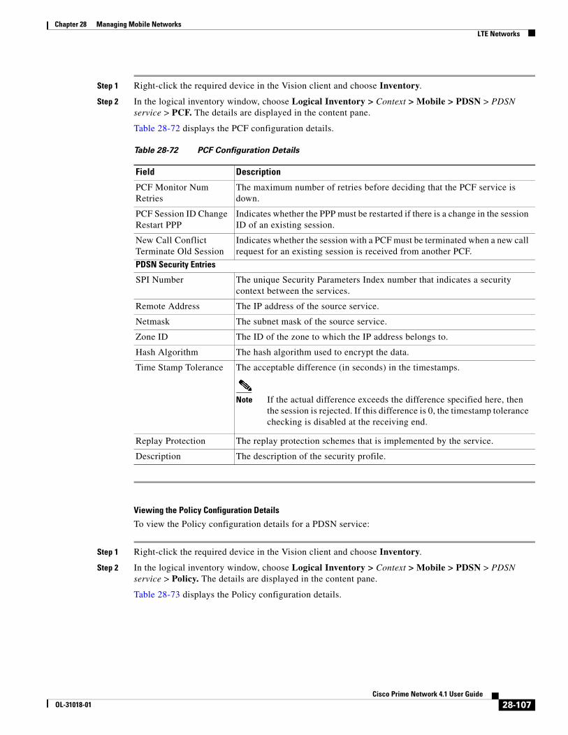
Chapter 28 Managing Mobile Networks LTE Networks
Step 1 Right-click the required device in the Vision client and choose Inventory.
Step 2 In the logical inventory window, choose Logical Inventory > Context > Mobile > PDSN > PDSN service > PCF. The details are displayed in the content pane.
Table 28-72 displays the PCF configuration details.
Viewing the Policy Configuration Details
To view the Policy configuration details for a PDSN service:
Step 1 Right-click the required device in the Vision client and choose Inventory.
Step 2 In the logical inventory window, choose Logical Inventory > Context > Mobile > PDSN > PDSN service > Policy. The details are displayed in the content pane.
Table 28-73 displays the Policy configuration details.
Table 28-72 PCF Configuration Details
Field Description
PCF Monitor Num Retries
The maximum number of retries before deciding that the PCF service is down.
PCF Session ID Change Restart PPP
Indicates whether the PPP must be restarted if there is a change in the session ID of an existing session.
New Call Conflict Terminate Old Session
Indicates whether the session with a PCF must be terminated when a new call request for an existing session is received from another PCF.
PDSN Security Entries
SPI Number The unique Security Parameters Index number that indicates a security context between the services.
Remote Address The IP address of the source service.
Netmask The subnet mask of the source service.
Zone ID The ID of the zone to which the IP address belongs to.
Hash Algorithm The hash algorithm used to encrypt the data.
Time Stamp Tolerance The acceptable difference (in seconds) in the timestamps.
Note If the actual difference exceeds the difference specified here, then the session is rejected. If this difference is 0, the timestamp tolerance checking is disabled at the receiving end.
Replay Protection The replay protection schemes that is implemented by the service.
Description The description of the security profile.
28-107Cisco Prime Network 4.1 User Guide
OL-31018-01

Chapter 28 Managing Mobile Networks LTE Networks
Viewing the PPP Configuration Det4
To view the Point-to-Point Protocol details for a PDSN service:
Step 1 Right-click the required device in the Vision client and choose Inventory.
Step 2 In the logical inventory window, choose Logical Inventory > Context > Mobile > PDSN > PDSN service > PPP. The details are displayed in the content pane.
Table 28-74 displays the PPP configuration details.
Table 28-73 Policy Configuration Details
Field Description
Unknown CVSE Policy Indicates whether the unknown Critical Vendor Specific Extension (CVSE) policy is enforced.
RRQ MEI From Current PCF
Indicates whether PPP must be restarted after getting MEI in RRQ.
New Call Policy The call policy for one or all the services, which can be any one of the following:
• Accept
• Reject
• Redirect
• Reject on MSID
• Redirect on MSID
• None
This field defaults to None.
Overload Policy The action to be taken by the PDSN service in case of an overload condition.
Overload Policy Reject Code
The reject code for the overload policy.
Service Option Policy The policy followed by PDSN for configuring services.
Reject MSID The Mobile Station Identifier (MSID) for which new calls are rejected.
Note If the New Call Policy field is set to Reject MSID, then this field will display the relevant MSID.
28-108Cisco Prime Network 4.1 User Guide
OL-31018-01

Chapter 28 Managing Mobile Networks LTE Networks
Viewing the QoS Configuration Details
To view the Quality of Service configuration details for a PDSN service:
Step 1 Right-click the required device in the Vision client and choose Inventory.
Step 2 In the logical inventory window, choose Logical Inventory > Context > Mobile PDSN > PDSN service > QoS. The details are displayed in the content pane.
Table 28-75 displays the QoS configuration details.
Table 28-74 PPP Configuration Details
Field Description
Context Name The destination context where the Layer 2 Tunneling protocol Access Concentrator (LAC) service is configured.
Note This context is the same as the PPP tunneling context.
Tunnel Type The type of the PPP tunnel established between the PDSN and the PFC, which can be any one of the following values:
• L2TP
• None
This field defaults to None.
Fragment State Indicates whether the PPP fragmentation is enabled. By default, this is option is disabled.
Alt PPP Indicates whether the Alternate Point-to-Point (PPP) protocol sessions are enabled for the PDSN service. By default, this option is disabled.
Allow No Authentication
Indicates whether subscribers can gain network access even if they have not been authenticated.
Authentication The authentication mode and priority when multiple modes are selected, which can be any one of the following:
• chap—Uses the Challenge Handshake Authentication Protocol (CHAP) for authentication. Must be followed by a priority value, which can be any value between 0 and 1000 with a lower number indicating higher preference. This protocol is enabled by default and commands the highest priority.
• mschap—Uses the Microsoft Challenge Handshake Authentication Protocol (MS-CHAP) for authentication. Must be followed by a priority value, which can be any value between 0 and 1000 with a lower number indicating higher preference. This protocol is disabled by default.
• pap—Uses Password Authentication Protocol (PAP) for authentication. Must be followed by a priority value, which can be any value between 0 and 1000 with a lower number indicating higher preference. This protocol seconds CHAP in terms of priority. This protocol is enabled by default.
28-109Cisco Prime Network 4.1 User Guide
OL-31018-01
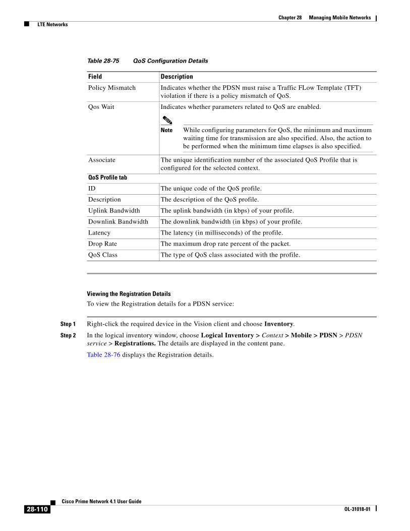
Chapter 28 Managing Mobile Networks LTE Networks
Viewing the Registration Details
To view the Registration details for a PDSN service:
Step 1 Right-click the required device in the Vision client and choose Inventory.
Step 2 In the logical inventory window, choose Logical Inventory > Context > Mobile > PDSN > PDSN service > Registrations. The details are displayed in the content pane.
Table 28-76 displays the Registration details.
Table 28-75 QoS Configuration Details
Field Description
Policy Mismatch Indicates whether the PDSN must raise a Traffic FLow Template (TFT) violation if there is a policy mismatch of QoS.
Qos Wait Indicates whether parameters related to QoS are enabled.
Note While configuring parameters for QoS, the minimum and maximum waiting time for transmission are also specified. Also, the action to be performed when the minimum time elapses is also specified.
Associate The unique identification number of the associated QoS Profile that is configured for the selected context.
QoS Profile tab
ID The unique code of the QoS profile.
Description The description of the QoS profile.
Uplink Bandwidth The uplink bandwidth (in kbps) of your profile.
Downlink Bandwidth The downlink bandwidth (in kbps) of your profile.
Latency The latency (in milliseconds) of the profile.
Drop Rate The maximum drop rate percent of the packet.
QoS Class The type of QoS class associated with the profile.
28-110Cisco Prime Network 4.1 User Guide
OL-31018-01
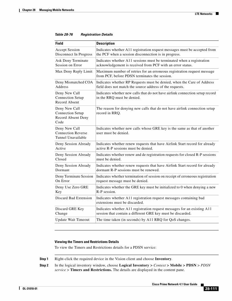
Chapter 28 Managing Mobile Networks LTE Networks
Viewing the Timers and Restrictions Details
To view the Timers and Restrictions details for a PDSN service:
Step 1 Right-click the required device in the Vision client and choose Inventory.
Step 2 In the logical inventory window, choose Logical Inventory > Context > Mobile > PDSN > PDSN service > Timers and Restrictions. The details are displayed in the content pane.
Table 28-76 Registration Details
Field Description
Accept Session Disconnect In Progress
Indicates whether A11 registration request messages must be accepted from the PCF when a session disconnection is in progress.
Ask Deny Terminate Session on Error
Indicates whether A11 sessions must be terminated when a registration acknowledgement is received from PCF with an error status.
Max Deny Reply Limit Maximum number of retries for an erroneous registration request message from PCF, before PDSN terminates the session.
Deny Mismatched COA Address
Indicates whether RP Requests must be denied, when the Care of Address field does not match the source address of the requests.
Deny New Call Connection Setup Record Absent
Indicates whether new calls that do not have airlink connection setup record in the RRQ must be denied.
Deny New Call Connection Setup Record Absent Deny Code
The reason for denying new calls that do not have airlink connection setup record in RRQ.
Deny New Call Connection Reverse Tunnel Unavailable
Indicates whether new calls whose GRE key is the same as that of another user must be denied.
Deny Session Already Active
Indicates whether renew requests that have Airlink Start record for already active R-P sessions must be denied.
Deny Session Already Closed
Indicates whether renew and de registration requests for closed R-P sessions must be denied.
Deny Session Already Dormant
Indicates whether renew requests that have Airlink Start record for already dormant R-P sessions must be renewed.
Deny Terminate Session On Error
Indicates whether termination of session on receipt of erroneous registration request message must be denied.
Deny Use Zero GRE Key
Indicates whether the GRE key must be initialized to 0 when denying a new R-P session.
Discard Bad Extension Indicates whether A11 registration request messages containing bad extensions must be discarded.
Discard GRE Key Change
Indicates whether A11 registration request messages for an existing A11 session that contain a different GRE key must be discarded.
Update Wait Timeout The time taken (in seconds) by A11 RRQ for QoS changes.
28-111Cisco Prime Network 4.1 User Guide
OL-31018-01

Chapter 28 Managing Mobile Networks LTE Networks
Table 28-77 Timers and Restrictions Details
Field Description
Inter PDSN Handoff Indicates whether the Inter-PDSN handoff feature off is enabled. Inter-PDSN handoff relates to the handoff between two PCFs with connectivity to different PDSNs.
Note Inter-PDSN handoff can be of two types: Fast Handoff and Dormant Handoff. Fast Handoff uses a GRE tunnel between two PDSNs to transport user data for a single service instance. Dormant Handoff occurs when a mobile station with a dormant packet session determines that it has crossed a packet zone boundary.
Inter PDSN Handover Use CANIDPANID
Indicates whether usage of Current Access Network ID (CANID) or Previous Access Network ID (PAN) is supported during an Inter-PDSN handover.
Data Available Indicator
Indicates whether data transfer is available.
PMA Capability Indicator
The Proxy Mobile Agent capability (PMA) indicator, which determines whether PMIP is supported by Prime Network.
Note PDSN sends the capability indicator through RADIUS to the AAA server as an access-request packet to indicate to the AAA server that PDSN supports PMIP. If the capability indicator attribute is missing, then PMIP is not supported by PDSN.
Direct LTE Indicator Indicates whether PDSN can send Direct LTE indicator in the Access Request.
Data Over Signalling Indicates whether data transfer over a10 signalling channel instead of bearer or subscriber channels from PCF or PDSN is allowed. By default, this feature is not allowed.
Dormant Transition Indicates whether dormant transition of the RP link during the initial setup of the subscriber session is allowed. If this option is disabled, then the subscriber session will be disconnected if the RP link becomes dormant during the initial setup.
ROHC IP Header Compression
Indicates whether the Robust Header Compression (ROHC) is enabled for headers in the IP packets that are being sent by or sent to the PDSN. By default, this option is disabled.
Always On Indication Indicates whether the Always On feature is enabled for a subscriber.
Note When the idle-time out limit runs out for a subscriber, the IP/PPP session remains connected as long as the subscriber is reachable. By default, this feature is disabled.
Setup TimeOut The maximum time (in seconds) allowed for a session to be setup between PCF and PDSN. This time can be any value between 1 and 1000000, and defaults to 60 seconds.
28-112Cisco Prime Network 4.1 User Guide
OL-31018-01

Chapter 28 Managing Mobile Networks LTE Networks
Configuration Commands for PDSN
The following PDSN commands can be launched from the logical inventory by choosing the Context > Commands > Configuration or Context > Commands > Show. Your permissions determine whether you can run these commands (see ). To find out if a device supports these commands, see the Cisco Prime Network 4.0 Supported Cisco VNEs.
Retransmission TimeOut
The timeout period (in seconds) for retransmission of RP control packets. This time can be any value between 1 and 1000000 and defaults to 3 seconds.
Pdsn Type0 Tft Indicates whether Traffic Flow Template (TFT) of the PDSN is changed from type 0 TFT to type 1 TFT.
Tft Validation TimeOut The TFT validation timeout (in seconds) for QoS changes. This time can be any value between 1 and 100000, and defaults to 0.
Access Flow Traffic Violations
The number of violations that are permitted in the access flow traffic.
Access Flow Traffic Violations Interval
The time interval between two subsequent access flow traffic violations.
Table 28-77 Timers and Restrictions Details (continued)
Field Description
Table 28-78 PDSN Configuration Commands
Command Navigation Description
Create PDSN Right-click on a context > Commands > Configuration
Use this command to create a new PDSN service for the selected context.
Modify PDSN
Delete PDSN
Expand PDSN node > Right-click PDSN service > Commands > Configuration
Use these commands to modify/delete an existing PDSN service configured for the selected context.
Show PDSN Expand PDSN node > Right-click PDSN service > Commands > Show
Use this command to view and confirm the PDSN service configuration details.
Modify GRE Expand PDSN node > PDSN service > right-click GRE > Commands > Configuration
Use this command to modify the Generic Routing Encapsulation (GRE) configuration settings for a specified PDSN service.
Modify IP Source Violation
Expand PDSN node > PDSN service > Right-click IP Source Violation > Commands > Configuration
Use this command to modify the IP Source Violation configuration details for the specified PDSN service.
Modify MSID
Expand PDSN node > PDSN service > Right-click MSID > Commands > Configuration
Use this command to modify the mobile station ID (MSID) configuration details for the specified PDSN service.
Modify PCF Parameters
Expand PDSN node > PDSN service > Right-click PCF > Commands > Configuration
Use this command to modify the Packet Control Function (PCF) configuration details for the specified PDSN service.
28-113Cisco Prime Network 4.1 User Guide
OL-31018-01

Chapter 28 Managing Mobile Networks LTE Networks
Viewing the Local Mobility Anchor Configuration (LMA)
Proxy Mobile IPv6 (or PMIPv6, or PMIP) is a network-based mobility management protocol for building a common access technology independent of mobile core networks, accommodating various access technologies such as WiMAX, 3GPP, 3GPP2 and WLAN based access architectures.
The PMIPv6 provides network-based IP Mobility management to a mobile node, without requiring the participation of the MN in any IP mobility-related signaling. The mobility entities in the network track the movements of the MN, initiate the mobility signaling, and set up the required routing state.
The major functional entities of PMIPv6 are Mobile Access Gateways (MAGs), Local Mobility Anchors (LMAs), and Mobile Nodes (MNs).
The Local Mobility Anchor (LMA) is the home agent for a mobile node in a Proxy Mobile IPv6 (PMIPv6) domain. It is the topological anchor point for mobile node home network prefixes and manages the binding state of an mobile node. An LMA has the functional capabilities of a home agent as defined in the Mobile IPv6 base specification (RFC 3775) along with the capabilities required for supporting the PMIPv6 protocol.
To view the LMA configuration details:
Step 1 Right-click the required device in the Vision client and choose Inventory.
Step 2 In the logical inventory window, choose Logical Inventory >C ontext > Mobile > LMA. The list of LMA services configured in Prime Network is displayed in the content pane.
Create PCF Security Entry
Expand PDSN node > Right-click PDSN service > Commands > Configuration
Use this command to create a new PCF security entry.
Modify PCF Security Entry
Delete PCF Security Entry
Expand PDSN node > PDSN service > PCF > Under Security Profiles tab n the content pane, right-click SPI Number > Commands > Configuration
Use these commands to modify/delete the PCF security entry details.
Modify Policy
Expand PDSN node > PDSN service > Right-click Policy > Commands > Configuration
Use this command to modify the policy configuration details for the PDSN service.
Modify PPP Expand PDSN node > PDSN service > Right-click PPP > Commands > Configuration
Use this command to modify the Point-to-Point Protocol configuration details for the selected PDSN service.
Modify Registrations
Expand PDSN node > PDSN service > Right-click Registrations > Commands > Configuration
Use this command to modify the registration details for the selected PDSN service.
Modify Timers and Registrations
EExpand PDSN node > PDSN service > Right-click Timers and Registrations > Commands > Configuration
Use this command to modify the timers and registration details for the selected PDSN service.
Table 28-78 PDSN Configuration Commands (continued)
Command Navigation Description
28-114Cisco Prime Network 4.1 User Guide
OL-31018-01

Chapter 28 Managing Mobile Networks LTE Networks
Step 3 From the LMA node, choose an LMA service. The LMA service details are displayed in the content pane.
Figure 28-19 LMA Service Details
Table 28-79 displays the LMA service details.
28-115Cisco Prime Network 4.1 User Guide
OL-31018-01

Chapter 28 Managing Mobile Networks LTE Networks
Table 28-79 LMA Service Details
Field Description
Service Name The unique service name of the LMA.
Status The status of the LMA service, which can be any one of the following:
• Down
• Running
• Initiated
• Unknown.
This field defaults to Down.
Local IPv6 Address The IP address of the interface serving as S2a (that is connected to HSGW) or S5/S8 (that is connected to S-GW) interface.
Local IPv4 Address The IP address of the interface connected to HA/P-GW.
Local IP Port The User Datagram Protocol (UDP) port for the LMA service.
Max Subscribers The maximum number of subscribers that the LMA service can support. This number can be any value between 0 and 3000000.
Default Subscriber Name
The name of the subscriber template to be used for subscribers who are using this domain alias.
Mobility Option Type Value
The mobility option type used in mobility messages, which can be any one of the following:
• Custom 1
• Custom 2
• Standard
Refresh Advice Option Indicates whether refresh advice option must be included in the Binding Acknowledgement sent by the LMA service. By default, this option is disabled.
Refresh Interval The percent of granted lifetime to be used in the Refresh Interval Mobility option pertaining to the Binding Acknowledgement sent by the LMA service. This percentage can be any value between 1 and 99 and defaults to 75.
Setup Timeout The maximum time (in seconds) allowed for the session to setup. This field defaults to 60.
Lifetime The registration lifetime (in seconds) of the mobile IPv6 session. This number can be any value between 1 and 262140.
Bind Revocation Indicates whether the binding revocation support is available for the LMA service. By default, this option is disabled.
Bind Revocation Max Retries
The maximum number of retries for the binding revocation, which can be any value between 1 and 10. This field defaults to 3.
Bind Revocation Timeout
The time interval (in milliseconds) of the retransmission of the binding revocation, which can be any value between 500 and 10000. This field defaults to 3000.
Sequence Number Validation
Indicates whether the sequence number of the MIPv6 control packet received by the LMA service must be validated. This option is enabled by default.
28-116Cisco Prime Network 4.1 User Guide
OL-31018-01

Chapter 28 Managing Mobile Networks Scheduling 3GPP Inventory Retrieval Requests
Scheduling 3GPP Inventory Retrieval RequestsThe 3GPP Inventory Management Web Services for Prime Network Integration Layer (PN-IL) retrieves the physical and logical inventory data from the Prime Network managed devices. For details on supported network elements, see Cisco Prime Network 4.0 Supported Cisco VNEs. For more details on the 3GPP inventory management and the web services, refer to the Cisco Prime OSS Integration Guide, 2.0.
Prime Network allows you to schedule a web service operations for Prime Network Integration Layer to run immediately or at a later point in time. Using Prime Network - Web Service Scheduler option, you can do the following:
• Select the inventory request type based on which the inventory data will be retrieved from either all the supported devices or from the specified devices under Prime Network.
• Schedule the 3GPP inventory management web service operations to initiate the inventory request and executes it according to the specified schedule.
To schedule web services:
Step 1 In the Vision client, Events client, or Administration client, choose Tools > Web Service Scheduler.
Step 2 In the Web Service Scheduler window, select General tab and select the inventory request type.
Table 28-80 describes the details of the Web Service Scheduler - General tab.
Signalling Packet IP Header DSCP
The Differentiated Services Code Point (DSCP) marking that is applicable to the IP header that is carrying outgoing signalling packets.
Simultaneous Binding The maximum number of Care of addresses that can be bound for the same user as identified by their Network Access Identifier (NAI) and home address. This can be any value ranging from 1 to 3. This field defaults to 1.
Standalone Mode Indicates whether the LMA service can be started in the standalone mode. This option is disabled by default.
Timestamp Option Validation
Indicates whether the Timestamp option in the Binding Acknowledgement must be validated. This option is disabled by default.
Timestamp Tolerance The time (in seconds) to validate Timestamp reply protection, which can be any value between 0 and 65535. This field defaults to 7 seconds.
AAA Accounting Indicates whether the AAA Accounting information for subscriber sessions must be sent. This option is enabled by default.
New Call Policy Indicates whether the new call policy must be accepted or rejected. By default, this field is set to None.
Table 28-79 LMA Service Details (continued)
Field Description
28-117Cisco Prime Network 4.1 User Guide
OL-31018-01

Chapter 28 Managing Mobile Networks Scheduling 3GPP Inventory Retrieval Requests
Step 3 Click Execute to initiate the inventory request and check the output files as specified in the Response message.
Step 4 Click the Scheduling tab to schedule the web services to run later or click on Run Now option to run web services immediately.
Step 5 To schedule the web services for a later date/time:
a. Select the Schedule Job radio button. The scheduling options Once and Recurring are enabled.
b. To execute the webservice operation once, select the Once radio button and specify the date and time.
c. To schedule the web services operation execution on a recurring basis, select the Recurring radio button and specify the following:
– The date and time range for the recurrence.
– How often you want to initiate the inventory request within that time range - every X minutes, daily, weekly, or monthly.
Step 6 Specify comments, if required and click Schedule. Prime Network initiates the inventory request and executes it according to your scheduling specifications. Go to the Scheduled Jobs page (Tools > Scheduled Jobs), to check that your inventory request job has been created. You can use the Scheduled Jobs page to monitor the job status and to reschedule a job if necessary. You can also clone a scheduled job and edit the criteria, if required.
Table 28-80 General Tab in Web Service Scheduler
Field Description
Operation Select from the following inventory request:
• getAllInventory - This inventory request is used to retrieve Inventory data for all supported devices under Prime Network. One notification will be issued by Prime Network Integration Layer upon completion of file creation for all supported network elements
• getManagedElement - This inventory request is used to retrieve the inventory data for a specific managed element. One notification will be sent by the Prime Network Integration Layer for the specific managed element.
Note For information on how to subscribe to a notification, see the Cisco Prime OSS Integration Guide, 2.0.
Managed Element This options appears only if the inventory request type selected is of getManagedElement type. This option allows you to select a specific managed element, i.e, ASR5000 or ASR5500 for which inventory data will be retrieved.
28-118Cisco Prime Network 4.1 User Guide
OL-31018-01

Chapter 28 Managing Mobile Networks Viewing Operator Policies, APN Remaps, and APN Profiles
Viewing Operator Policies, APN Remaps, and APN ProfilesOperator policy provides mechanisms to fine tune the behavior of subsets of subscribers above and beyond the behaviors described in the user profile. It can also be used to control the behavior of visiting subscribers in roaming scenarios, enforcing roaming agreements, and providing a measure of local protection against foreign subscribers.
An operator policy associates APNs, APN profiles, an APN remap table, and a call-control profile to ranges of International Mobile Subscriber Identities (IMSIs). These profiles and tables are created and defined within their own configuration modes to generate sets of rules and instructions that can be reused and assigned to multiple policies. In this manner, an operator policy manages the application of rules governing the services, facilities, and privileges available to subscribers. These policies can override standard behaviors and provide mechanisms for an operator to get around the limitations of other infrastructure elements, such as DNS servers and HSSs.
Note Operator policies and APN profiles are applicable only for the ‘local’ context in the logical inventory.
The following topics explain how to view operator policies, APN remaps, and APN profiles in the Vision client:
• Viewing Operator Policies, page 28-119
• Viewing APN Remaps, page 28-121
• Viewing APN Profiles, page 28-123
Viewing Operator PoliciesOperator policies provide an operator with a range of control to manage the services, facilities, and privileges available to subscribers. By configuring the various components of an operator policy, the operator fine tunes any desired restrictions or limitations needed to control call handling and this can be done for a group of callers within a defined IMSI range or per subscriber.
Besides enhancing operator control through configuration, the operator policy feature minimizes configuration by drastically reducing the number of configuration lines needed. Operator policy maximizes configurations by breaking them into the following reusable components that can be shared across IMSI ranges or subscribers:
• Call-control profiles
• IMEI profiles (SGSN only)
• APN profiles
• APN remap tables
• Operator policies
• IMSI ranges
To view operator policies in logical inventory:
Step 1 Right-click the required device in the Vision client and choose Inventory.
Step 2 In the logical inventory window, choose Logical Inventory > local > Mobile > Policy > Operator Policies
28-119Cisco Prime Network 4.1 User Guide
OL-31018-01

Chapter 28 Managing Mobile Networks Viewing Operator Policies, APN Remaps, and APN Profiles
The Vision client displays the list of operator policies configured under the container. You can view the individual policy details from the table on the right pane or by choosing Logical Inventory > local > Mobile > Policy > Operator Policies > Policy.
Table 28-81 describes the details available for each operator policy.
If an operator policy is configured with IMEI ranges and APN entries, the details are displayed in the respective tabs IMEI Ranges and APN Entries on the content pane.
Table 28-81 Operator Policies in Logical Inventory
Field Description
Name Name of the operator policy.
Description Description of the operator policy.
Call Control Profile Name
Name of the call control profile associated with the operator policy.
Call Control Validity Indicates whether the call control profile name associated with the operator policy is valid or is not created yet (invalid).
APN Remap Table Name
Name of the APN remap table associated with the operator policy.
APN Remap Table Validity
Indicates whether the APN remap table name associated with the operator policy is valid or is not created yet (invalid).
Default APN Profile Name
Name of the default APN profile associated with the operator policy.
Default APN Profile Validity
Indicates whether the default APN profile name associated with the operator policy is valid or is not created yet (invalid).
IMEI Ranges
Start Range The starting number in the range of IMEI profiles.
To Range The ending number in the range of IMEI profiles.
Software Version Software version to fine tune the IMEI definition.
Profile Name Name of the IMEI profile associated with the IMEI range. Displays ‘None’, if no profile is associated with the range.
Validity Validity of the IMEI profile.
APN Entries
NI APN network identifier.
NI APN Profile Name of the APN profile associated with the network identifier. An APN profile groups a set of APN-specific parameters that may be applicable to one or more APNs. When a subscriber requests an APN that has been identified in a selected operator policy, the parameter values configured in the associated APN profile are applied.
NI APN Profile Validity Indicates whether the NI APN profile associated with the operator policy is valid or is not created yet (invalid).
OI APN operator identifier.
28-120Cisco Prime Network 4.1 User Guide
OL-31018-01

Chapter 28 Managing Mobile Networks Viewing Operator Policies, APN Remaps, and APN Profiles
Viewing APN RemapsAn APN remap tables allow an operator to override an APN specified by a user, or the APN selected during the normal APN selection procedure, as specified by 3GPP TS 23.060. This level of control enables operators to deal with situations such as:
• An APN is provided in the activation request that does not match with any of the subscribed APNs; either a different APN was entered or the APN could have been misspelled. In such situations, the SGSN rejects the activation request. It is possible to correct the APN, creating a valid name so that the activation request is not rejected.
• In some cases, an operator might want to force certain devices or users to use a specific APN. For example, a set of mobile users may need to be directed to a specific APN. In such situations, the operator needs to override the selected APN.
An APN remap table group is a set of APN-handling configurations that may be applicable to one or more subscribers. When a subscriber requests an APN that has been identified in a selected operator policy, the parameter values configured in the associated APN remap table are applied. For example, an APN remap table allows configuration of the following:
• APN aliasing—Maps incoming APN to a different APN, based on partial string match (MME and SGSN) or matching charging characteristic (SGSN only).
• Wildcard APN—Allows APN to be provided by the SGSN, when wildcard subscription is present and the user has not requested an APN.
• Default APN—Allows a configured default APN to be used, when the requested APN cannot be used.
APN remap tables are configured with commands in the APN Remap Table configuration mode. A single APN remap table can be associated with multiple operator policies, but an operator policy can only be associated with a single APN remap table.
To view APN remap properties in logical inventory:
Step 1 Right-click the required device in the Vision client and choose Inventory.
Step 2 In the logical inventory window, choose Logical Inventory > local > Mobile > Profile > APN Remaps
The Vision client displays the list of APN remaps configured under the container. You can view the individual APN remap details from the table on the right pane or by choosing Logical Inventory > local > Mobile > Profile > APN Remaps > APN Remap.
OI APN Profile Name of the APN profile associated with the operator identifier. An APN profile groups a set of APN-specific parameters that may be applicable to one or more APNs. When a subscriber requests an APN that has been identified in a selected operator policy, the parameter values configured in the associated APN profile are applied.
OI APN Profile Indicates whether the OI APN profile associated with the operator policy is valid or is not created yet (invalid).
Table 28-81 Operator Policies in Logical Inventory (continued)
Field Description
28-121Cisco Prime Network 4.1 User Guide
OL-31018-01

Chapter 28 Managing Mobile Networks Viewing Operator Policies, APN Remaps, and APN Profiles
Table 28-82 describes the details available for each APN remap.
If an APN remap is configured with charging characteristics and NI and OI entries, the details are displayed in the respective tabs Charging Characteristics and Network And Operator Identifier Entries on the content pane.
Step 3 If a default APN is configured for the remap, click the Default APN node under the APN remap. You can view the following details on the content pane.
Table 28-82 APN Remap Properties in Logical Inventory
Field Description
Name Name of the APN remap.
Description Description of the APN remap.
APN When No APN Requested
APN network identifier that will be used when no APN is requested.
Wildcard APN for IPv4 Wildcard APN included in the subscriber record, with PDP type as IPv4 context.
Wildcard APN for IPv6 Wildcard APN included in the subscriber record, with PDP type as IPv6 context.
Wildcard APN for IPv4v6
Wildcard APN included in the subscriber record, with PDP type as both IPv4 and IPv6 contexts.
Wildcard APN for PPP Wildcard APN included in the subscriber record, with PDP type as PPP context.
Charging Characteristics
Profile Index Profile index in charging characteristics.
Behavior Bit Value Behavior bit in charging characteristics.
APN For Overriding Name of the APN profile that the charging characteristic attributes must be applied to, to generate CDRs.
Network And Operator Identifier Entries
Requested NI The old network identifier that is being mapped for replacement.
Mapped to NI The new network identifier.
NI Wildcard Replace String
When a wildcard character is included in the old APN network identifier, this parameter identifies the information to replace the wildcard in the new APN network identifier.
Requested OI The old operator identifier that is being mapped for replacement.
Mapped to OI The new operator identifier.
OI MNC Replace String When a wildcard character is included in the MNC portion of the old APN operator identifier, this parameter identifies the information to replace the wildcard in the new APN operator identifier.
OI MCC Replace String When a wildcard character is included in the MCC portion of the old APN operator identifier, this parameter identifies the information to replace the wildcard in the new APN operator identifier.
28-122Cisco Prime Network 4.1 User Guide
OL-31018-01

Chapter 28 Managing Mobile Networks Viewing Operator Policies, APN Remaps, and APN Profiles
Viewing APN ProfilesAPN Profile defines a set of parameters controlling the SGSN or MME behavior, when a specific APN is received or no APN is received in a request. An APN profile is a key element in the Operator Policy feature. An APN profile is not used or valid unless it is associated with an APN and this association is specified in an operator policy.
Essentially, an APN profile is a template which groups a set of APN-specific commands that may be applicable to one or more APNs. When a subscriber requests an APN that has been identified in a selected operator policy, then the set of commands in the associated APN profile will be applied. The same APN profile can be associated with multiple APNs and multiple operator policies.
An APN profile groups a set of APN-specific parameters that may be applicable to one or more APNs. When a subscriber requests an APN that has been identified in a selected operator policy, the parameter values configured in the associated APN profile are applied. For example:
• Enable or disable a direct tunnel (DT) per APN (SGSN).
• Define charging characters for calls associated with a specific APN.
• Identify a specific GGSN to be used for calls associated with a specific APN (SGSN).
• Define various quality of service (QoS) parameters to be applied to calls associated with a specific APN.
• Restrict or allow PDP context activation on the basis of access type for calls associated with a specific APN.
A single APN profile can be associated with multiple operator policies.
To view APN profile properties in logical inventory:
Step 1 Right-click the required device in the Vision client and choose Inventory.
Step 2 In the logical inventory window, choose Logical Inventory > local > Mobile > Profile > APN Profiles.
Table 28-83 Default APN Properties in Logical Inventory
Field Description
Default APN Name Name of the default APN.
Use Default APN When No APN is Requested
Indicates whether the configured default APN can be used or not, if there is no APN in the request.
Use Default APN When DNS Query Fails
Indicates whether the configured default APN can be used or not, if DNS query fails.
Fallback APN to Use A fallback APN to be used when the configured default APN is not present in the subscription, so that activation does not fail.
Fallback APN in First Subscription
Indicates whether APN from the first subscription record must be used, when the configured default APN is not available.
Use APN From Single Subscription Record
Indicates whether APN from the subscription record must be used, if it is the only record available and the normal APN selection fails.
28-123Cisco Prime Network 4.1 User Guide
OL-31018-01
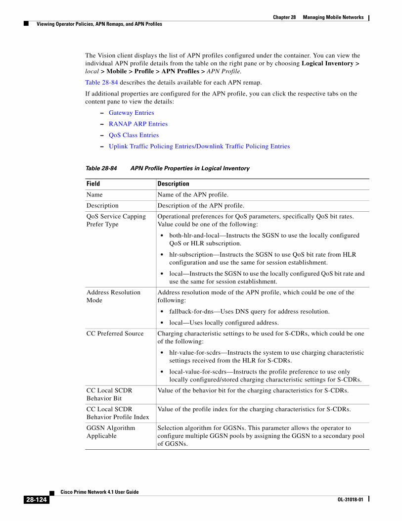
Chapter 28 Managing Mobile Networks Viewing Operator Policies, APN Remaps, and APN Profiles
The Vision client displays the list of APN profiles configured under the container. You can view the individual APN profile details from the table on the right pane or by choosing Logical Inventory > local > Mobile > Profile > APN Profiles > APN Profile.
Table 28-84 describes the details available for each APN remap.
If additional properties are configured for the APN profile, you can click the respective tabs on the content pane to view the details:
– Gateway Entries
– RANAP ARP Entries
– QoS Class Entries
– Uplink Traffic Policing Entries/Downlink Traffic Policing Entries
Table 28-84 APN Profile Properties in Logical Inventory
Field Description
Name Name of the APN profile.
Description Description of the APN profile.
QoS Service Capping Prefer Type
Operational preferences for QoS parameters, specifically QoS bit rates. Value could be one of the following:
• both-hlr-and-local—Instructs the SGSN to use the locally configured QoS or HLR subscription.
• hlr-subscription—Instructs the SGSN to use QoS bit rate from HLR configuration and use the same for session establishment.
• local—Instructs the SGSN to use the locally configured QoS bit rate and use the same for session establishment.
Address Resolution Mode
Address resolution mode of the APN profile, which could be one of the following:
• fallback-for-dns—Uses DNS query for address resolution.
• local—Uses locally configured address.
CC Preferred Source Charging characteristic settings to be used for S-CDRs, which could be one of the following:
• hlr-value-for-scdrs—Instructs the system to use charging characteristic settings received from the HLR for S-CDRs.
• local-value-for-scdrs—Instructs the profile preference to use only locally configured/stored charging characteristic settings for S-CDRs.
CC Local SCDR Behavior Bit
Value of the behavior bit for the charging characteristics for S-CDRs.
CC Local SCDR Behavior Profile Index
Value of the profile index for the charging characteristics for S-CDRs.
GGSN Algorithm Applicable
Selection algorithm for GGSNs. This parameter allows the operator to configure multiple GGSN pools by assigning the GGSN to a secondary pool of GGSNs.
28-124Cisco Prime Network 4.1 User Guide
OL-31018-01
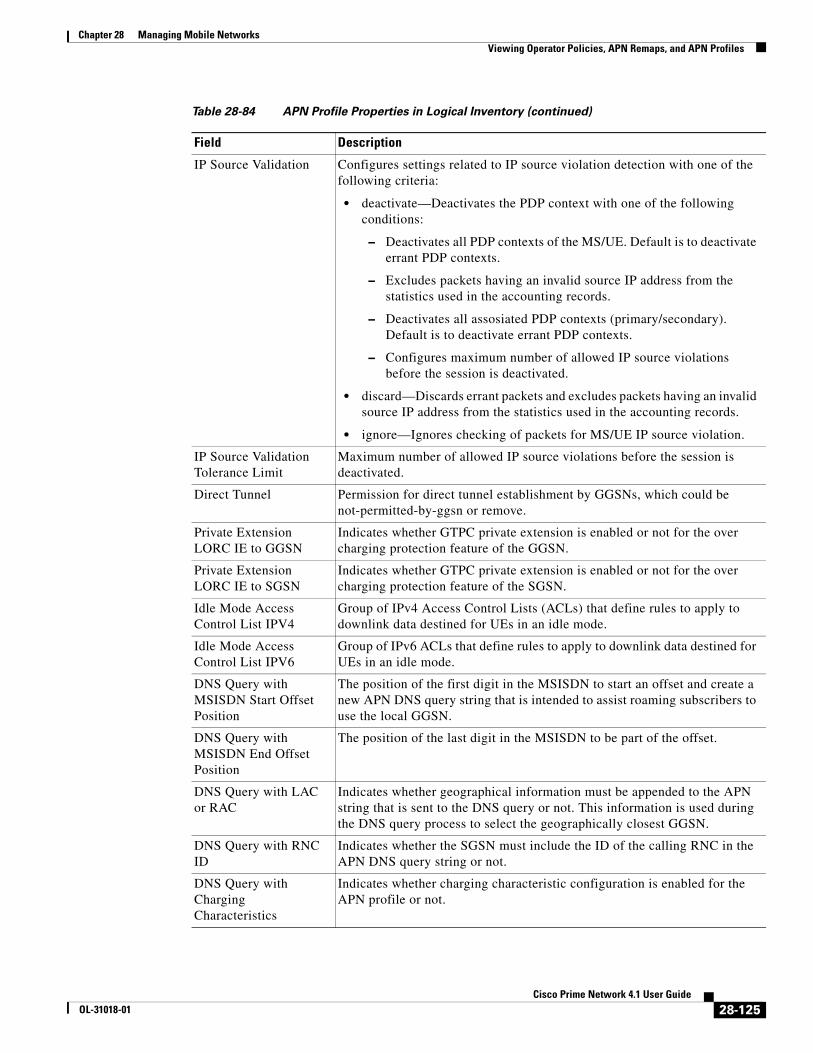
Chapter 28 Managing Mobile Networks Viewing Operator Policies, APN Remaps, and APN Profiles
IP Source Validation Configures settings related to IP source violation detection with one of the following criteria:
• deactivate—Deactivates the PDP context with one of the following conditions:
– Deactivates all PDP contexts of the MS/UE. Default is to deactivate errant PDP contexts.
– Excludes packets having an invalid source IP address from the statistics used in the accounting records.
– Deactivates all assosiated PDP contexts (primary/secondary). Default is to deactivate errant PDP contexts.
– Configures maximum number of allowed IP source violations before the session is deactivated.
• discard—Discards errant packets and excludes packets having an invalid source IP address from the statistics used in the accounting records.
• ignore—Ignores checking of packets for MS/UE IP source violation.
IP Source Validation Tolerance Limit
Maximum number of allowed IP source violations before the session is deactivated.
Direct Tunnel Permission for direct tunnel establishment by GGSNs, which could be not-permitted-by-ggsn or remove.
Private Extension LORC IE to GGSN
Indicates whether GTPC private extension is enabled or not for the over charging protection feature of the GGSN.
Private Extension LORC IE to SGSN
Indicates whether GTPC private extension is enabled or not for the over charging protection feature of the SGSN.
Idle Mode Access Control List IPV4
Group of IPv4 Access Control Lists (ACLs) that define rules to apply to downlink data destined for UEs in an idle mode.
Idle Mode Access Control List IPV6
Group of IPv6 ACLs that define rules to apply to downlink data destined for UEs in an idle mode.
DNS Query with MSISDN Start Offset Position
The position of the first digit in the MSISDN to start an offset and create a new APN DNS query string that is intended to assist roaming subscribers to use the local GGSN.
DNS Query with MSISDN End Offset Position
The position of the last digit in the MSISDN to be part of the offset.
DNS Query with LAC or RAC
Indicates whether geographical information must be appended to the APN string that is sent to the DNS query or not. This information is used during the DNS query process to select the geographically closest GGSN.
DNS Query with RNC ID
Indicates whether the SGSN must include the ID of the calling RNC in the APN DNS query string or not.
DNS Query with Charging Characteristics
Indicates whether charging characteristic configuration is enabled for the APN profile or not.
Table 28-84 APN Profile Properties in Logical Inventory (continued)
Field Description
28-125Cisco Prime Network 4.1 User Guide
OL-31018-01

Chapter 28 Managing Mobile Networks Viewing Operator Policies, APN Remaps, and APN Profiles
DNS Query Charging Characteristics ID Format
Format of the charging characteristic information to be included.
Gateway Entries
Gateway Entry Gateway entry configured for the APN profile.
IP Address IPv4 or IPv6 addresses of the gateway configured.
Priority Priority of the gateway to consider during address selection.
Weight Weightage or importance assigned to the gateway for load balancing.
Pool Gateway pool assigned.
Gateway Type Type of gateway configured, which could be GGSN or P-GW.
RANAP ARP Entries
Traffic Class Traffic class of the Radio Access Network Application Part (RANAP) configuration.
Subscription Priority Subscription priority of the traffic class; the lowest number denoting the highest priority.
Priority Level Priority level for the subscription priority.
Preemption Capability Preemption capability value of the traffic class.
Preemption Vulnerability
Preemption vulnerability value of the traffic class.
Queuing Allowed Indicates whether queuing is allowed for the traffic class or not.
QoS Class Entries
Class Name Traffing class of the QoS configuration.
Service Delivery Unit Delivery Order
Indicates whether bearer should provide in-sequence delivery of service data units (SDUs) or not.
Delivery of Erroneous Service Delivery Units
Indicates whether SDUs detected as erroneous should be delivered or discarded.
Max Bit Rate Uplink Maximum bit rate, in kbps, allowed for uplink between MS and the core network.
Max Bit Rate Downlink Maximum bit rate, in kbps, allowed for downlink between MS and the core network.
Allocation Retention Priority
Relative importance compared to other Radio Access Bearers (RABs) for allocation and retention of the RAB.
Traffic Handling Priority
Relative importance for traffic handling when compared to other RABs.
SDU Max Size Maximum allowed SDU size, in bytes.
SDU Error Ratio Fraction of SDUs lost or detected as erroneous.
Guaranteed Bit Rate Uplink
Uplink bit rate, in kbps, that is assured for a given RAB between MS and the core network.
Guaranteed Bit Rate Downlink
Downlink bit rate, in kbps, that is assured for a given RAB between MS and the core network.
Table 28-84 APN Profile Properties in Logical Inventory (continued)
Field Description
28-126Cisco Prime Network 4.1 User Guide
OL-31018-01

Chapter 28 Managing Mobile Networks Viewing Operator Policies, APN Remaps, and APN Profiles
Viewing Additional Characteristics of an APN Profile
To view additional characteristics of an APN profile:
Step 1 Right-click the required device in the Vision client and choose Inventory.
Step 2 In the logical inventory window, choose Logical Inventory > local > Mobile > Profile > APN Profiles > APN Profile.
Minimum Transfer Delay
Minimum transfer delay, in milliseconds.
Residual BER Undetected bit error ratio (BER) in the delivered SDUs.
MBR Map Down Attribute that maps or converts the received HLR maximum bit rate (MBR) (from value) to a locally configured downlink MBR value (to value).
MBR Map Up Attribute that maps or converts the received HLR MBR (from value) to a locally configured uplink MBR value (to value).
Uplink Traffic Policing Entries/Downlink Traffic Policing Entries
Traffic Class Traffic class of the QoS configuration.
Burst Size Auto Readjust
Indicates whether the auto readjustment of burst size is enabled or disabled. This parameter is used in dynamic burst size calculation, for traffic policing, at the time of PDP activation or modification.
Burst Size Auto Readjust Duration
The burst size readjustment duration in seconds. This parameter indicates the number of seconds that the dynamic burst size calculation will last for. This allows the traffic to be throttled at the negotiated rates.
Peak Burst Size (bytes) The peak burst size allowed, in bytes, for the uplink/downlink direction and QoS class.
Guaranteed Burst Size (bytes)
The guaranteed burst size allowed, in bytes, for the uplink/downlink direction and QoS class.
Exceed Action The action to be taken on packets that exceed the committed data rate, but do not violate the peak data rate. The action could be one of the following:
• Drop
• Lower IP Precedence
• Transmit
Violate Action The action to be taken on packets that exceed both committed and peak data rates. The action could be one of the following:
• Drop
• Lower IP Precedence
• Shape
• Transmit
Table 28-84 APN Profile Properties in Logical Inventory (continued)
Field Description
28-127Cisco Prime Network 4.1 User Guide
OL-31018-01

Chapter 28 Managing Mobile Networks Viewing Operator Policies, APN Remaps, and APN Profiles
Step 3 Expand the APN Profile node. The following list of characteristics configured for the APN profile are displayed:
– PDP Inactivity Actions—Attributes related to PDP data inactivity. Once a data communication is in progress there are cases where this data communication can be inactive after some time, for example, when the user has locked the phone after browsing the internet or when the battery suddenly drains out. In such a case, the SGSN can take a configured action based on this inactivity. The inactivity timeout and the actions that can be taken based on certain conditions are modeled in this configuration.
– QoS to DSCP Mapping (Downlink) / Qos to DSCP Mapping (Uplink)—Mapping of QoS parameters to DSCP. Configuration of the local values for the traffic class (TC) parameters for QoS configured for the APN.
– PDP Restrictions (UMTS) / PDP Restrictions (GPRS)—Activation restrictions on PDP.
Step 4 Click each of one of these characteristics to view its properties on the right pane. See Table 28-85 for more details on the properties of each characteristics configured for the APN profile.
Table 28-85 APN Profile Additional Characteristics
Field DescriptionPDP Inactivity Actions
PDP Inactivity Idle Timeout
Timeout duration for PDP inactivity. PDP context is deactivated, if it is inactive for the given duration.
PDP Inactivity Idle Timeout Action
Action to be taken when the PDP data communication is inactive for the timeout duration.
PDP Inactivity Idle Timeout Action Condition
Condition when the GPRS detach procedure should be executed on the PDP context, when the timeout is reached or exceeded.
PDP IPV4 IPV6 Override
PDP type to use, per APN, if dual PDP type addressing is not supported by the network.
QoS to DSCP Mapping (Downlink) / Qos to DSCP Mapping (Uplink)
Conversational Real time conversational traffic class of service, which is reserved for voice traffic.
Streaming Streaming traffic class of service, which handes one-way, real-time data transmission, such as streaming video or audio.
Interactive Threshold Priority 1/2/3
Interactive traffic class of service with threshold priorities 1, 2, and 3.
Background Background traffic class of service. This best-effort class manages traffic that is handled as a background function, such as e-mail, where time to delivery is not a key factor.
Interactive TP1 Alloc P1/P2/P3
Interactive traffic class of service, with threshold priority 1 and allocation priorities 1, 2, and 3.
Interactive TP2 Alloc P1/P2/P3
Interactive traffic class of service, with threshold priority 2 and allocation priorities 1, 2, and 3.
Interactive TP3 Alloc P1/P2/P3
Interactive traffic class of service, with threshold priority 3 and allocation priorities 1, 2, and 3.
PDP Restrictions (UMTS) / PDP Restrictions (GPRS)
28-128Cisco Prime Network 4.1 User Guide
OL-31018-01

Chapter 28 Managing Mobile Networks Working with Active Charging Service
Working with Active Charging ServiceEnhanced Charging Service (ECS), also known as Active Charging Service (ACS), is an in-line service, which is integrated within the platform and provides mobile operators the ability to offer tiered, detailed, and itemized billing to subscribers. Data packets flow through the ECS subsystem and relevant actions are performed based on the configured rules. Charging records (xCDRs) will be generated and forwarded to ESS or billing systems for prepaid and post paid billing.
The major components and functions of an ECS solution are given below.
Content Service Steering
Content Service Steering (CSS) enables directing selective subscriber traffic into the ECS subsystem. CSS uses Access Control Lists (ACLs) to redirect selective subscriber traffic flows. ACLs control the flow of packets into and out of the system. ACLs consist of rules (ACL rules) or filters that control the action taken on packets matching the filter criteria.
ACLs are configurable on a per-context basis and apply to a subscriber through either a subscriber profile (for PDSN) or an APN profile (for GGSN) in the destination context.
Protocol Analyzer
Protocol analyzer stack is responsible for analyzing the individual protocol fields during packet inspection. The analyzer supports the following types of packet inspection:
• Shallow Packet Inspection—Inspection of the Layer 3 (IP header) and Layer 4 (for example, UDP or TCP header) information.
• Deep Packet Inspection—Inspection of Layer 7 and above information. This functionality includes:
– Detection of Uniform Resource Identifier (URI) information at level 7 (example, HTTP)
– Identification of true destination in the case of terminating proxies, where shallow packet inspection only reveals the destination IP address/port number of a terminating proxy
Rule Definitions
Rule definitions (ruledefs) are user-defined expressions, based on protocol fields and protocol states, which define what actions to take when specific field values are true.
Most important rule definitions are related to Routing and Charging as explained below:
• Routing Ruledefs—Routing ruledefs are used to route packets to content analyzers. Routing ruledefs determine which content analyzer to route the packet to, when the protocol fields and/or protocol states in ruledef expression are true.
QoS Class Background Indicates whether background traffic class of service is enabled or not.
QoS Class Interactive Indicates whether interactive traffic class of service is enabled or not.
QoS Class Streaming Indicates whether streaming traffic class of service is enabled or not.
QoS Class Conversational
Indicates whether conversational traffic class of service is enabled or not.
Table 28-85 APN Profile Additional Characteristics (continued)
Field Description
28-129Cisco Prime Network 4.1 User Guide
OL-31018-01

Chapter 28 Managing Mobile Networks Working with Active Charging Service
• Charging Ruledefs—Charging ruledefs are used to specify what action to take based on the analysis done by the content analyzers. Actions can include redirection, charge value, and billing record emission.
Rule Base
A rule base is a collection of rule definitions and their associated billing policy. The rule base determines the action to be taken when a rule is matched. Rule bases can also be used to apply the same rule definitions for several subscribers, which eliminate the need to have unique rule definition for each subscriber. We can set priority, default bandwidth policy, type of billing for subscriber sessions, for a rule definition or group of rule definitions in the rule base.
Content Filtering
ACS also offers a content filtering mechanism. Content filtering is an in-line service available for 3GPP and 3GPP2 networks to filter HTTP and WAP requests from mobile subscribers, based on the URLs in the requests. Content filtering uses the DPI feature of ECS to discern HTTP and WAP requests. This enables operators to filter and control the content that an individual subscriber can access, so that subscribers are inadvertently not exposed to universally unacceptable content and/or content inappropriate as per the subscribers’ preferences.
The content filtering service offers the following solutions:
• URL Blacklisting—With this solution, all HTTP/WAP URLs in subscriber requests are matched against a database of blacklisted URLs. If there is a match, the flow is discarded, redirected, or terminated as configured. If there is no match, subscribers view the content as they would normally.
• Category-based Content Filtering
– Category-based Static Content Filtering—In this method, all HTTP/WAP URLs in subscriber requests are matched against a static URL categorization database. Action is taken based on a URL’s category, and the action configured for that category in the subscriber’s content filtering policy. Possible actions include permitting, blocking, redirecting, and inserting content.
– Category-based Static-and-Dynamic Content Filtering—In this method, each URL first undergoes static rating. If the URL cannot be rated by the static database or if the URL static rating categorizes a URL as either Dynamic or Unknown, the requested content is sent for dynamic rating; wherein the requested content is analyzed and categorized. Action is taken based on the category determined by dynamic rating, and the action configured for that category in the subscriber’s content filtering policy. Possible actions include permitting, blocking, redirecting, and inserting content.
Note ACS is applicable only for the ‘local’ context in the logical inventory.
The following topics explain how to work with ACS in the Vision client:
• Viewing Active Charging Services, page 28-131
• ACS Commands, page 28-144
28-130Cisco Prime Network 4.1 User Guide
OL-31018-01

Chapter 28 Managing Mobile Networks Working with Active Charging Service
Viewing Active Charging ServicesYou can view the active charging services in logical inventory as shown in Figure 28-20.
Figure 28-20 Mobile Technology Setup Nodes
Additionally, you can also perform the following for each ACS:
• Viewing Content Filtering Categories, page 28-133
• Viewing Credit Control Properties, page 28-133
• Viewing Charging Action Properties
• Viewing Rule Definitions
• Viewing Rule Base for the Charging Action
• Viewing Bandwidth Policies
• Viewing Fair Usage Properties
To view ACS details in logical inventory:
Step 1 Right-click the required device in the Vision client and choose Inventory.
Step 2 In the logical inventory window, choose Logical Inventory > local > Mobile > Active Charging Services.
The Vision client displays the list of active charging services configured under the container. You can view the individual ACS details from the table on the right pane or by choosing Logical Inventory > local > Mobile > Active Charging Services > ACS.
Table 28-86 describes the details available for each ACS.
28-131Cisco Prime Network 4.1 User Guide
OL-31018-01

Chapter 28 Managing Mobile Networks Working with Active Charging Service
Table 28-86 Active Charging Services in Logical Inventory
Field Description
Service Name Name of the active charging service.
TCP Flow Idle Timeout Maximum duration, in seconds, a TCP flow can remain idle.
UDP Flow Idle Timeout Maximum duration, in seconds, a UDP flow can remain idle.
ICMP Flow Idle Timeout
Maximum duration, in seconds, an Internet Control Message Protocol (ICMP) flow can remain idle.
ALG Media Idle Timeout
Maximum duration, in seconds, an application level gateway (ALG) media flow can remain idle.
TCP Flow Mapping Idle Timeout
The time for which the TCP flow mapping timer holds the resources.
UDP Flow Mapping Idle Timeout
The time for which the UDP flow mapping timer holds the resources.
Deep Packet Inspection Indicates whether configuration of DPI is enabled or disabled in the mobile video gateway.
Passive Mode Indicates whether the ACS is in or out of passive mode operation.
CDR Flow Control Indicates whether flow control is enabled or disabled between the ACS Manager (ACSMGR) and Charging Data Record Module (CDRMOD).
CDR Flow Control Unsent Queue Size
Flow control unsent queue size at ACSMGR level.
Unsent Queue High Watermark
Highest flow control unsent queue size at ACSMGR level.
Unsent Queue Low Watermark
Lowest flow control unsent queue size at ACSMGR level.
Content Filtering Indicates whether content filtering is enabled or disabled for the ACS.
Dynamic Content Filtering
Indicates whether dynamic content filtering is enabled or disabled for the ACS.
URL Blacklisting Indicates whether URL blacklisting is enabled or disabled for the ACS.
URL Blacklisting Match Method
Method to look up the URLs in the URL blacklisting database.
Content Filtering Match Method
Method to look up the URLs in the category-based content filtering database.
Interpretation of Charging Rulebase Name
Charging rulebase configured for the ACS.
Selected Charging Rulebase Name for AVP
Charging rulebase name for attribute value pair (AVP) configured for the ACS.
28-132Cisco Prime Network 4.1 User Guide
OL-31018-01

Chapter 28 Managing Mobile Networks Working with Active Charging Service
Viewing Content Filtering Categories
To view content filtering categories in logical inventory:
Step 1 Right-click the required device in the Vision client and choose Inventory.
Step 2 In the logical inventory window, choose Logical Inventory > local > Mobile > Active Charging Services > ACS > Content Filtering Categories.
The Vision client displays the list of content filtering categories configured under the container. You can view the individual content filtering category details from the table on the right pane or by choosing Logical Inventory > local > Mobile > Active Charging Services > ACS > Content Filtering Categories > Content Filtering Category.
Table 28-87 describes the details available for each content filtering category.
Viewing Credit Control Properties
In a prepaid environment, the subscribers pay for a service prior to using it. While the subscriber is using the service, credit is deducted from subscriber’s account until it is exhausted or the call ends. In prepaid charging, ECS performs the metering function. Credits are deducted in real time from an account balance or quota. A fixed quota is reserved from the account balance and given to the system by a prepaid rating and charging server, which interfaces with an external billing system platform. The system deducts
Table 28-87 Content Filtering Categories in Logical Inventory
Field Description
Policy ID ID of the content filtering policy.
Failure Action Action to take for the content filtering analysis result.
EDR File The EDR file name.
Content Category Name of the content filtering category.
Content Insert Content string to insert in place of the message returned from prohibited or restricted site or content server.
Content Priority Precedence of the category in the content filtering policy.
Content Failure Action Action to take for the indicated result of the content filtering analysis, which could be one of the following:
• allow
• content-insert
• discard
• redirect URL
• terminate flow
• www-reply-code-and-terminate-flow
Content Redirect Content string to redirect the subscriber to a specified URL.
Content Reply Code Reply code to terminate flow.
EDR File Format Predefined EDR file format.
28-133Cisco Prime Network 4.1 User Guide
OL-31018-01
Chapter 28 Managing Mobile Networks Working with Active Charging Service
volume from the quota according to the traffic analysis rules. When the subscriber’s quota gets to the threshold level specified by the prepaid rating and charging server, system sends a new access request message to the server and server updates the subscriber's quota. The charging server is also updated at the end of the call.
ECS supports the following credit control applications for prepaid charging:
• RADIUS Credit Control Application—RADIUS is used as the interface between ECS and the prepaid charging server.
• Diameter Credit Control Application—The Diameter Credit Control Application (DCCA) is used to implement real-time credit control for a variety of services, such as networks access, messaging services, and download services.
To view credit control properties in logical inventory:
Step 1 Right-click the required device in the Vision client and choose Inventory.
Step 2 In the logical inventory window, choose Logical Inventory > local > Mobile > Active Charging Services > ACS > Credit Control.
The Vision client displays the list of credit control groups configured under the container. You can view the individual credit control group details from the table on the right pane or by choosing Logical Inventory > local > Mobile > Active Charging Services > ACS > Credit Control > Credit Control Group.
You can also view the following details by clicking the respective node under the credit control group:
• Diameter
• Failure Handling
• Pending Traffic Treatment
• Quota
• Server Unreachable Failure Handling
Table 28-88 describes the details available for each credit control group.
28-134Cisco Prime Network 4.1 User Guide
OL-31018-01

Chapter 28 Managing Mobile Networks Working with Active Charging Service
Table 28-88 Credit Control Properties in Logical Inventory
Field Description
Group Name of the credit control group for the subscriber.
Mode Prepaid charging application mode, which could be Diameter or Radius.
APN Name to be Included
Type of APN name sent in the credit control application (CCA) message.
Trigger Type Condition based on which credit reauthorization is triggered from the server.
Diameter MSCC Final Unit Action Terminate
Indicates whether to terminate a PDP session immediately when the Final-Unit-Action (FUA) in a particular multi service credit control (MSCC) is set as Terminate and the quota is exhausted for that service, or to terminate the session after all MSCCs (categories) have used their available quota.
Diameter Peer Select table
Peer Primary hostname.
Realm Realm for the primary host.
Secondary Peer Secondary hostname.
Secondary Realm Realm for the secondary host.
IMSI Range Mode Mode of peer selection based on IMSI prefix or suffix.
IMSI Start Value Starting value of the IMSI range for peer selection.
IMSI End Value Ending value of the IMSI range for peer selection.
Diameter
End Point Name Name of the diameter endpoint.
End Point Realm Realm of the diameter endpoint.
Pending Timeout Maximum time to wait for response from a diameter peer.
Session Failover Indicates whether diameter session failover is enabled or not.
Dictionary Diameter credit control dictionary for the ACS.
Failure Handling
Initial Request Failure handling behavior, if failure takes place during initial session establishment. Value could be continue, retry-and-terminate, and terminate.
Update Request Failure handling behavior, if failure takes place during update request. Value could be continue, retry-and-terminate, and terminate.
Terminate Request Failure handling behavior, if failure takes place during terminate request. Value could be continue, retry-and-terminate, and terminate.
Pending Traffic Treatment
Trigger Indicates whether to allow or drop a trigger while waiting for the credit information from the server. Value could be pass or drop.
Forced Reauth Indicates whether to allow or drop reauthorization while waiting for the credit information from the server. Value could be pass or drop.
NoQuota Indicates whether to allow or drop traffic, if there is no quota present. Value could be pass, drop, or buffer.
Quota Exhausted Indicates whether to allow or drop traffic, if quota is exhausted. Value could be pass, drop, or buffer.
28-135Cisco Prime Network 4.1 User Guide
OL-31018-01

Chapter 28 Managing Mobile Networks Working with Active Charging Service
Viewing Charging Action Properties
Charging Action is an action taken on the incoming data packets once the data packets are treated by the routing and charging rule components. User can configure independent actions such as allow, forward, and block traffic, and bind these actions with other routing and charging rule components.
To view charging action properties in logical inventory:
Step 1 Right-click the required device in the Vision client and choose Inventory.
Step 2 In the logical inventory window, choose Logical Inventory > local > Mobile > Active Charging Services > ACS > Charging Action.
The Vision client displays the list of charging actions configured under the container as shown. You can view the individual charging action details from the table on the right pane or by choosing Logical Inventory > local > Mobile > Active Charging Services > ACS > Charging Action > Charging Action.
You can also view the following details by clicking the respective node under the Charging Action node:
• Allocation Retention Priority
• Bandwidth
• Flow Action
• QoS
Validity Expired Indicates whether to allow or drop traffic, if quota validity is expired. Value could be pass or drop.
Quota
Request Trigger Action taken on the packet that triggers the credit control application to request quota. Value could be exclude-packet-causing-trigger or include-packet-causing-trigger.
Holding Time Duration for which ECS can hold the quota before returning to the credit control server.
Validity Time Lifetime for which subscriber quota retrieved from the billing server is valid.
Time Threshold Time threshold limit for subscriber quota in the prepaid credit control service.
Units Threshold Unit threshold limit for subscriber quota in the prepaid credit control service.
Volume Threshold Volume threshold limit for subscriber quota in the prepaid credit control service.
Server Unreachable Failure Handling
Initial Request Failure handling behavior if server is unreachable during initial session establishment. Value could be continue or terminate.
Update Request Failure handling behavior if server is unreachable during update request. Value could be continue or terminate.
Table 28-88 Credit Control Properties in Logical Inventory (continued)
Field Description
28-136Cisco Prime Network 4.1 User Guide
OL-31018-01

Chapter 28 Managing Mobile Networks Working with Active Charging Service
• Video
• Billing Action
Table 28-89 describes the details available for each charging action record.
Table 28-89 Charging Action Properties in Logical Inventory
Field Description
Name Name of the charging action.
Content ID Content ID to use in the generated billing records as well the AVP used by the credit control application.
Service ID Configured service ID used to associate the charging action in rule definitions configuration.
Charging EDR Name Name of the EDR format for the billing action in the ACS.
EGCDRs Indicates whether eG-CDRs must be generated when the subscriber session ends or an interim trigger condition occurs.
Rf Indicates whether Rf accounting is enabled or not.
UDRs Indicates whether UDRs must be generated based on the UDR format declared in the rule base.
Flow Idle Timeout Maximum duration a flow can remain idle after which the system automatically terminates the flow.
Limit for Flow Type State
Indicates whether the limit for flow type is configured or not.
Limit for Flow Type Value
Maximum number of flows of a particular type.
Limit for Flow Type Action
Action to be taken, if the number of flows exceeds the maximum limit.
IP Type of Service IP Type of Service (ToS) octets used in the charging action.
Retransmission Count Indicates whether to count the number of packet retransmissions when the charging action is applied on the incoming data packets.
Content Filtering Indicates whether content filtering must be applied on the incoming packets or not.
Credit Control Indicates whether to apply credit control or not.
Credit Rating Group Coupon ID used in prepaid charging as rating group.
Charge Volume Method used for charge volume calculation based on the protocol and packet.
Next Hop Forwarding Address
Next hop forwarding address for a charging action.
VLAN ID VLAN ID configured for the subscriber
Flow Mapping Idle Timeout
Maximum duration, in seconds, a flow can remain idle after which the system automatically terminates the flow.
Allocation Retention Priority
Priority Level Priority value that indicates whether to accept or reject a request for establishment or modification of a bearer in a limited resource condition.
28-137Cisco Prime Network 4.1 User Guide
OL-31018-01
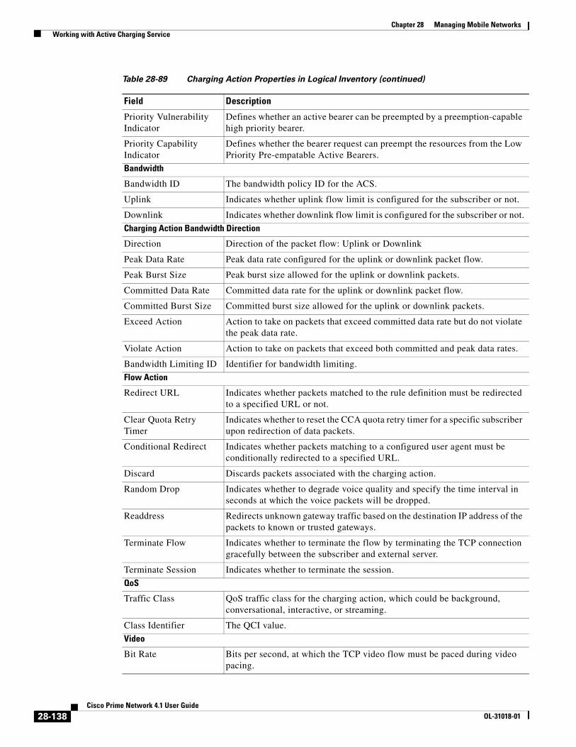
Chapter 28 Managing Mobile Networks Working with Active Charging Service
Priority Vulnerability Indicator
Defines whether an active bearer can be preempted by a preemption-capable high priority bearer.
Priority Capability Indicator
Defines whether the bearer request can preempt the resources from the Low Priority Pre-empatable Active Bearers.
Bandwidth
Bandwidth ID The bandwidth policy ID for the ACS.
Uplink Indicates whether uplink flow limit is configured for the subscriber or not.
Downlink Indicates whether downlink flow limit is configured for the subscriber or not.
Charging Action Bandwidth Direction
Direction Direction of the packet flow: Uplink or Downlink
Peak Data Rate Peak data rate configured for the uplink or downlink packet flow.
Peak Burst Size Peak burst size allowed for the uplink or downlink packets.
Committed Data Rate Committed data rate for the uplink or downlink packet flow.
Committed Burst Size Committed burst size allowed for the uplink or downlink packets.
Exceed Action Action to take on packets that exceed committed data rate but do not violate the peak data rate.
Violate Action Action to take on packets that exceed both committed and peak data rates.
Bandwidth Limiting ID Identifier for bandwidth limiting.
Flow Action
Redirect URL Indicates whether packets matched to the rule definition must be redirected to a specified URL or not.
Clear Quota Retry Timer
Indicates whether to reset the CCA quota retry timer for a specific subscriber upon redirection of data packets.
Conditional Redirect Indicates whether packets matching to a configured user agent must be conditionally redirected to a specified URL.
Discard Discards packets associated with the charging action.
Random Drop Indicates whether to degrade voice quality and specify the time interval in seconds at which the voice packets will be dropped.
Readdress Redirects unknown gateway traffic based on the destination IP address of the packets to known or trusted gateways.
Terminate Flow Indicates whether to terminate the flow by terminating the TCP connection gracefully between the subscriber and external server.
Terminate Session Indicates whether to terminate the session.
QoS
Traffic Class QoS traffic class for the charging action, which could be background, conversational, interactive, or streaming.
Class Identifier The QCI value.
Video
Bit Rate Bits per second, at which the TCP video flow must be paced during video pacing.
Table 28-89 Charging Action Properties in Logical Inventory (continued)
Field Description
28-138Cisco Prime Network 4.1 User Guide
OL-31018-01

Chapter 28 Managing Mobile Networks Working with Active Charging Service
Viewing Rule Definitions
Rule definitions are user-defined expressions, based on protocol fields and protocol states, which define what actions to take when specific field values are true. Each rule definition configuration consists of multiple expressions applicable to any of the fields or states supported by the respective analyzers.
Rule definitions are of the following types:
• Routing—Used to route packets to content analyzers. Routing rule definitions determine which content analyzer to route the packet to when the protocol fields and/or protocol states in the rule definition expression are true. Up to 256 rule definitions can be configured for routing.
• Charging—Used to specify what action to take based on the analysis done by the content analyzers. Actions can include redirection, charge value, and billing record emission. Up to 2048 charging rule definitions can be configured in the system.
• Post-processing—Used for post-processing purposes. Enables processing of packets even if the rule matching for them has been disabled.
• TPO—Used for Traffic Performance Optimization (TPO) in-line service match-rule and match advertisement features.
To view rule definitions in logical inventory:
Step 1 Right-click the required device in the Vision client and choose Inventory.
Step 2 In the logical inventory window, choose Logical Inventory > local > Mobile > Active Charging Services > ACS > Rule Definitions.
The Vision client displays the list of rule definitions configured under the container. You can view the individual rule definition details from the table on the right pane or by choosing Logical Inventory > local > Mobile > Active Charging Services > ACS > Rule Definitions > Rule Definition.
CAE Readdressing Indicates whether Content Adaptation Engine (CAE) readdressing is enabled, allowing video traffic to be fetched from the CAEs in the CAE group.
Transrating Indicates whether transrating is enabled or not. Transrating is a mobile video feature that reduces the encoded bit rates by adjusting video encoding.
Target Rate Reduction Percentage of the input bit rate of a video flow.
Billing Action
EDR Name of the EDR format for the billing action in the ACS.
EGCDR Indicates whether eG-CDRs must be generated when the subscriber session ends or an interim trigger condition occurs.
Rf Indicates whether Rf accounting is enabled or not.
UDRs Indicates whether UDRs must be generated based on the UDR format declared in the rule base.
Radius Accounting Record
Indicates whether radius accounting is enabled or not.
Table 28-89 Charging Action Properties in Logical Inventory (continued)
Field Description
28-139Cisco Prime Network 4.1 User Guide
OL-31018-01

Chapter 28 Managing Mobile Networks Working with Active Charging Service
Table 28-90 describes the details available for each rule definition.
Viewing Rule Definition Groups
A rule definition group enables grouping the rule definitions into categories. A rule definition group may contain optimizable rule definitions. Whether a group is optimized or not is decided on whether all the rule definitions in the group can be optimized. When a new rule definition is added, it is checked if it is included in any rule definition group and whether it needs to be optimized or not.
To view rule definition groups in logical inventory:
Step 1 Right-click the required device in the Vision client and choose Inventory.
Step 2 In the logical inventory window, choose Logical Inventory > local > Mobile > Active Charging Services > ACS > Group of Rule Definitions.
The Vision client displays the list of rule definition groups configured under the container. You can view the individual rule definition group details from the table on the right pane or by choosing Logical Inventory > local > Mobile > Active Charging Services > ACS > Group of Rule Definitions > Rule Definition Group.
Table 28-90 Rule Definition Group Properties in Logical Inventory
Field Description
Name Name of the rule definition group.
Application Type Purpose of the rule definition, which could be charging, routing, post-processing, or Traffic Performance Optimization (TPO).
Copy Packet To Log Indicates whether to copy every packet that matches the rule to a log file.
Tethered Flow Check Indicates whether tethered flow check if enabled or not. Tethering detection flow check feature enables detection of subscriber data traffic flow originating from PC devices tethered to mobile smart phones, and also provides effective reporting to enable service providers take business decisions on how to manage such usage and to bill subscribers accordingly.
Multiline OR Indicates whether to apply the OR operator to all lines in a rule definition. This allows a single rule definition to specify multiple URL expressions.
Protocol Configuration
Protocol The protocol that this rule definition is applied on.
Fields Particular protocol field, which is applied on the data packets for inspection. Value could be, host, payload, or domain.
Operator Logical operator that indicates how to logically match the value in the field analyzed based on the data type.
Value Value of a particular protocol in a rule definition which has to be applied on the incoming data packets for inspection.
28-140Cisco Prime Network 4.1 User Guide
OL-31018-01

Chapter 28 Managing Mobile Networks Working with Active Charging Service
Table 28-91 describes the details available for each rule definition group.
Rule Definition Group Commands
The following RuleDef commands can be launched from the inventory by right-clicking a rule definition group and choosing Commands > Configuration or Commands > Show. Your permissions determine whether you can run these commands (see ). To find out if a device supports these commands, see the Cisco Prime Network 4.0 Supported Cisco VNEs.
Viewing Rule Base for the Charging Action
A rule base is a collection of rule definitions and their associated billing policy. The rule base determines the action to be taken when a rule is matched. A maximum of 512 rule bases can be specified in the ECS service. It is possible to define a rule definition with different actions.
Rule bases can also be used to apply the same rule definitions for several subscribers, which eliminate the need to have unique rule definition for each subscriber. We can set priority, default bandwidth policy, type of billing for subscriber sessions, for a rule definition/ group of rule definitions in the rule base. Additionally we can configure content based billing and firewall/NAT constituent to rule base.
To view a rule base in logical inventory:
Step 1 Right-click the required device in the Vision client and choose Inventory.
Step 2 In the logical inventory window, choose Logical Inventory > local > Mobile > Active Charging Services > ACS > Rulebase Container.
Table 28-91 Rule Definition Group Properties in Logical Inventory
Field Description
Name Name of the rule definition group.
Application Type Purpose of the rule definition group, which could be charging, routing, content filtering, post-processing, or Traffic Performance Optimization (TPO).
Dynamic Command Content Filtering Policy ID
Content filtering policy ID to add or remove dynamic commands from the rule definition group.
Table 28-92 Rule Definition Group Commands
Command Type Command Inputs Required and Notes
Configuration Delete Group of RuleDefs Delete the rule definition group.
Show Show Group of RuleDefs Display the group of rule definitions.
28-141Cisco Prime Network 4.1 User Guide
OL-31018-01

Chapter 28 Managing Mobile Networks Working with Active Charging Service
The Vision client displays the list of rule bases configured under the container. You can view the individual rule base details from the table on the right pane or by choosing Logical Inventory > local > Mobile > Active Charging Services > ACS > Rulebase Container > Rule Base.Table 28-93 describes the details available for each rule base record.
Table 28-93 Rule Base Properties in Logical Inventory
Field Description
Rulebase Name Name of the rule base.
Flow Any Error Charging Action
Charging action to be used for packets dropped due to any error conditions after data session is created.
Limit for Total Flows Maximum number of simultaneous uplink and downlink packet flows.
Limit for TCP Flows Maximum number simultaneous TCP packet flows per subscriber or APN allowed for a rulebase.
Limit for Non TCP Flows
Maximum number simultaneous non-TCP packet flows per subscriber or APN allowed for a rulebase.
Charging Rule Optimization
Internal optimization level to use, for improved performance, when evaluating each instance of the action.
QoS Renegotiation Timeout
Timeout value after which QoS renegotiation is performed.
RTP Dynamic Routing Indicates whether the Real Time Streaming Protocol (RTSP) and SDP analyzers are enabled to detect the start/stop of RTP (a Transport Protocol for Real-Time Applications) and RTP Control Protocol (RCP) flows.
Ignore Port Number In Application Header
Indicates whether to consider or ignore the port number embedded in the application.
Delayed Charging Indicates how to charge for the control traffic associated with an application.
XHeader Certificate Name
Name of the encryption certificate to be used for x-header encryption.
XHeader Reencryption Period
Indicates how often to regenerate the encryption key for x-header encryption.
Default Bandwidth Policy
Name of the default bandwidth policy per subscriber.
P2P Dynamic Routing Indicates whether P2P analyzer is enabled to detect the P2P applications flow configured in ACS.
Fair Usage Waiver Percentage
Waiver percent on top of the average available memory credits per session for the Fair Usage feature of active charging.
URL Blacklisting Action
Configured URL blacklisting action to take when the URL matches ones of the blacklisted URLs.
URL Blacklisting Content ID
Specific content ID for which URL blacklisting is enabled in the rulebase.
Charging Action Priorities tab
Charging rule definitions and their priorities in the rulebase.
Routing Action Priorities tab
Routing actions and their priorities in the rulebase.
Post Processing Action Priorities
Post-processing actions and their priorities in the rulebase.
28-142Cisco Prime Network 4.1 User Guide
OL-31018-01

Chapter 28 Managing Mobile Networks Working with Active Charging Service
Viewing Bandwidth Policies
Bandwidth policies are helpful in applying rate limit to potentially bandwidth intensive and service disruptive applications. Using this policy, the operator can police and prioritize subscribers’ traffic to ensure that no single or group of subscribers’ traffic negatively impacts another subscribers’ traffic. Each policy will be identified by a unique ID, which will be associated to a particular group. Bandwidth policies are used to control the direction (uplink/downlink) of bandwidth, peak data rate, and peak burst size, and the actions that need to be taken on violation, if the bandwidth exceeds the burst size and data rate.
To view bandwidth policy in logical inventory:
Step 1 Right-click the required device in the Vision client and choose Inventory.
Step 2 In the logical inventory window, choose Logical Inventory > local > Mobile > Active Charging Services > ACS > Bandwidth Policy Container.
The Vision client displays the list of bandwidth policies configured under the container. You can view the individual bandwidth policy details from the table on the right pane or by choosing Logical Inventory > local > Mobile > Active Charging Services > ACS > Bandwidth Policy Container > Bandwidth Policy.
Table 28-94 describes the details available for each bandwidth policy.
Viewing Fair Usage Properties
To view fair usage properties configured for the ACS:
Step 1 Right-click the required device in the Vision client and choose Inventory.
Step 2 In the logical inventory window, choose Logical Inventory > local > Mobile > Active Charging Services > ACS > Fair Usage.
The Vision client displays the details on the content pane.
Table 28-94 Bandwidth Policy Properties in Logical Inventory
Field Description
Name Name of the bandwidth policy configured.
Total Bandwidth ID Configured
Total number of bandwidth IDs configured.
Total Group Limit Configured
Total number of bandwidth group limits configured.
Flow Limit for Bandwidth ID and Group ID Associations and Group ID tables
Holds all bandwidth IDs and group IDs of the bandwidth policy.
28-143Cisco Prime Network 4.1 User Guide
OL-31018-01

Chapter 28 Managing Mobile Networks Working with Active Charging Service
Table 28-95 describes the fair usage properties.
ACS CommandsThe following ACS commands can be launched from the inventory by right-clicking an ACS and choosing Commands > Configuration or Commands > Show. Your permissions determine whether you can run these commands (see ). To find out if a device supports these commands, see the Cisco Prime Network 4.0 Supported Cisco VNEs.
Table 28-95 Fair Usage Properties in Logical Inventory
Field Description
CPU Threshold Percent Percentage of system CPU resources that the dynamic inline transrating feature is allowed to use.
Threshold Percent Percentage of system resources that the dynamic inline transrating feature is allowed to use.
Deactivate Margin Percent
Fair usage deactivate margin, below which monitor action is disabled.
Table 28-96 Active Charging Services Configuration Commands
Command Navigation Description
Create Ruledef
Expand Active Charging Services node > Right-click ACS service > Commands > Configuration
Rule definitions (Ruledefs) are user-defined expressions, based on protocol fields and/or protocol-states, which define what actions to take when specific field values are true.
Use this command to create a new rule definition for the selected ACS service.
Create group of Ruledefs
Expand Active Charging Services node > Right-click ACS service > Commands > Configuration
Group-of-Ruledefs enable grouping ruledefs into categories. When a group-of-ruledefs is configured in a rulebase, if any of the ruledefs within the group matches, the specified charging-action is performed, any more action instances are not.
Use this command to create a new group of rule definitions for the selected ACS service.
Create Rulebase
Expand Active Charging Services node > Right-click ACS service > Commands > Configuration
A rulebase is a collection of ruledefs and their associated billing policy. The rulebase determines the action to be taken when a rule is matched.
Use this command to create a new rule base for the selected ACS service.
28-144Cisco Prime Network 4.1 User Guide
OL-31018-01

Chapter 28 Managing Mobile Networks Working with Active Charging Service
Modify Active Charging Service
Delete Active Charging Service
Expand Active Charging Services node > Right-click ACS service > Commands > Configuration
Use these commands to modify/delete an Active Charging service created for the selected context.
Create Access Ruledef
Delete Access Ruledef
Expand Active Charging Services node > Right-click ACS service > Commands > Configuration > Access Ruledef
Use these commands to create/delete an access rule definition for the selected ACS service.
Show Access Ruledef
Expand Active Charging Services node > Right-click ACS service > Commands > Show
Use this command to view and confirm the access rule definitions configured for the service.
Create Host Pool
Modify Host Pool
Delete Host Pool
Expand Active Charging Services node > Right-click ACS service > Commands > Configuration > Host Pool
Host pools allow operators to group a set of host or IP addresses that share similar characteristics together. Access rule definitions (ruledefs) can be configured with host pools. Up to ten sets of IP addresses can be configured in each host pool.
Use these commands to create/modify/delete a host pool for the selected ACS service.
Create Charging Action
Expand Active Charging Services node > Right-click ACS service > Commands > Configuration
Charging Action is an action taken on the incoming data packets once the data packets are treated by the routing and charging rule components. You can configure independent actions such as allow, forward, and block traffic, and bind these actions with other routing and charging rule components.
Use this command to configure a charging action for a service.
Modify charging Action
Delete Charging Action
Expand Active Charging Services node > ACS service > Charging Actions > Right-click an charging action > Commands > Configuration
Use these commands to modify/delete a charging action for a service.
Show Charging Action
Expand Active Charging Services node > Right-click ACS service > Commands > Show
Use this command to view and confirm the charging action configuration details.
Table 28-96 Active Charging Services Configuration Commands (continued)
Command Navigation Description
28-145Cisco Prime Network 4.1 User Guide
OL-31018-01

Chapter 28 Managing Mobile Networks Mobile Technologies Commands: Summary
Mobile Technologies Commands: SummaryThe following table provides a summary of the commands you can use to configure and view mobile technologies under a particular context in the Vision client. Your permissions determine whether you can run these commands (see ). To find out if a device supports these commands, see the Cisco Prime Network 4.0 Supported Cisco VNEs.
Command Navigation Description
Create AAA Group
Context > Commands > Configuration
AAA refers to Authentication, Authorization, and Accounting, which is a security architecture for distributed systems that determines the access given to users for specific services and the amount of resources they have used.
Use this command to create a new AAA group.
Create APN APN is the access point name that is configured in the GGSN configurations.
Use this command to create a new APN service.
Create Active Charging Service
Enhanced Charging Service (ECS), also known as Active Charging Service (ACS), is an in-line service, which is integrated within the platform and provides mobile operators the ability to offer tiered, detailed, and itemized billing to subscribers.
Use this command to create a new ACS service.
Create EGTP Evolved GPRS Tunneling Protocol (EGTP) formulates the primary bearer plane protocol within an LTE / EPC architecture. It provides support for tunnel management including handover procedures within and across LTE networks.
Use this command to create an EGTP service.
28-146Cisco Prime Network 4.1 User Guide
OL-31018-01

Chapter 28 Managing Mobile Networks Mobile Technologies Commands: Summary
Create GGSN Context > Commands > Configuration
Gateway GPRS Support Node (GGSM) is the gateway between the GPRS wireless data network and other external packet data networks such as radio networks, IP networks, or private networks. GGSN provides network access to external hosts wishing to communicate with mobile subscribers (MS).
Use this command to create a GGSN service.
Create GTPP GPRS Tunneling Protocol Prime (GTPP) is used for communicating accounting messages to CGs.
Use this command to create a GTPP service.
Create GTPU GTPU carries user data within the GPRS core network and between the radio access network and the core network. The user data transported can be packets in any of IPv4, IPv6, or PPP formats.
Use this command to create a GTPU service.
Create IP Pool An IP pool is a sequential range of IP addresses within a certain network.
Use this command to create an IP Pool.
Create P-GW PDN Gateway (P-GW) is the node that terminates the SGi interface towards the PDN. If a UE is accessing multiple PDNs, there may be more than one P-GW for that UE.
Use this command to create a P-GW.
Create QCI-QOS Mapping
The QoS Class Index (QCI) to QoS mapping configuration mode is used to map QCIs to enforceable QoS parameters.
Use this command to create a QCI-QOS Mapping.
Create S-GW A Serving Gateway (S-GW) acts as a demarcation point between the Radio Access Network (RAN) and core network, and manages user plane mobility.
Use this command to create a S-GW.
Create VRF Virtual routing and forwarding (VRF) is a technology included in IP (Internet Protocol) network routers that allows multiple instances of a routing table to exist in a router and work simultaneously.
Use this command to create a VRF.
Delete Context Use this command to delete a context under the Logical Inventory node.
Modify License
Use this command to modify the license information.
Command Navigation Description
28-147Cisco Prime Network 4.1 User Guide
OL-31018-01
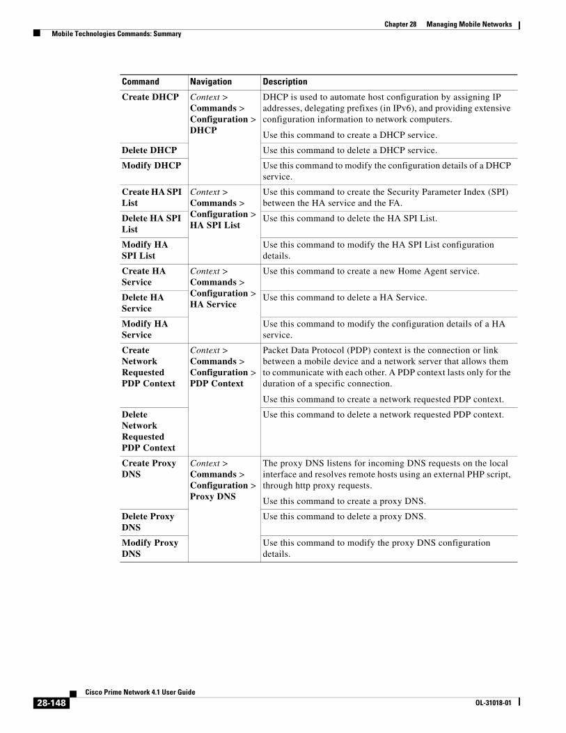
Chapter 28 Managing Mobile Networks Mobile Technologies Commands: Summary
Create DHCP Context > Commands > Configuration > DHCP
DHCP is used to automate host configuration by assigning IP addresses, delegating prefixes (in IPv6), and providing extensive configuration information to network computers.
Use this command to create a DHCP service.
Delete DHCP Use this command to delete a DHCP service.
Modify DHCP Use this command to modify the configuration details of a DHCP service.
Create HA SPI List
Context > Commands > Configuration > HA SPI List
Use this command to create the Security Parameter Index (SPI) between the HA service and the FA.
Delete HA SPI List
Use this command to delete the HA SPI List.
Modify HA SPI List
Use this command to modify the HA SPI List configuration details.
Create HA Service
Context > Commands > Configuration > HA Service
Use this command to create a new Home Agent service.
Delete HA Service
Use this command to delete a HA Service.
Modify HA Service
Use this command to modify the configuration details of a HA service.
Create Network Requested PDP Context
Context > Commands > Configuration > PDP Context
Packet Data Protocol (PDP) context is the connection or link between a mobile device and a network server that allows them to communicate with each other. A PDP context lasts only for the duration of a specific connection.
Use this command to create a network requested PDP context.
Delete Network Requested PDP Context
Use this command to delete a network requested PDP context.
Create Proxy DNS
Context > Commands > Configuration > Proxy DNS
The proxy DNS listens for incoming DNS requests on the local interface and resolves remote hosts using an external PHP script, through http proxy requests.
Use this command to create a proxy DNS.
Delete Proxy DNS
Use this command to delete a proxy DNS.
Modify Proxy DNS
Use this command to modify the proxy DNS configuration details.
Command Navigation Description
28-148Cisco Prime Network 4.1 User Guide
OL-31018-01

Chapter 28 Managing Mobile Networks Mobile Technologies Commands: Summary
Create Route Access List
Context > Commands > Configuration > Route Map and Route Access List
Access lists are a set of rules, organized in a rule table and are used to filter and identify traffic.
Use this command to create a new access list.
Create Route Map
Route maps are similar to access lists; they both have criteria for matching the details of certain packets and an action of permitting or denying those packets. Unlike access lists, though, route maps can add to each "match" criterion a "set" criterion that actually changes the packet in a specified manner, or changes route information in a specified manner.
Use this command to create a route map.
Delete Route Access List
Use this command to delete a route access list.
Delete Route Map
Use this command to delete a route map.
Modify Route Access List
Use this command to modify a route access list.
Modify Route Map
Use this command to modify a route map.
Create Subscribers
Context > Commands > Configuration > Subscriber
Use this command to create a new subscriber.
Delete Subscriber
Use this command to delete a subscriber.
Modify Subscriber
Use this command to modify subscriber details.
Show APN Context > Commands > Show
Use this command to view and confirm the APN configuration details.
Show DHCP Use this command to view and confirm the DHCP configuration details.
Show EGTP Use this command to view and confirm the EGTP configuration details.
Show HA SPI List
Use this command to view and confirm the HA SPI List details.
Show HA Service
Use this command to view and confirm the home agent service details.
Show IP Pool Use this command to view and confirm the IP Pool configuration details.
Show License Use this command to view and confirm the License details.
Show Route Access List
Use this command to view and confirm the Access list details.
Show Route Map
Use this command to view and confirm the Route Map details.
Show Subscriber
Use this command to view and confirm the Subscriber details.
Command Navigation Description
28-149Cisco Prime Network 4.1 User Guide
OL-31018-01

Chapter 28 Managing Mobile Networks Monitoring the Mobility Management Entity
Monitoring the Mobility Management EntityMobility Management Entity (MME) is the key control-node for an LTE access network, which works in conjunction with NodeB(eNodeB), Serving Gateway, or the LTE/SAW core network. It is responsible for initiating paging and authentication of mobile devices. It keeps location information at the Tracking Area Level for each user and chooses the right gateway during the initial registration process.
The MME uses the SSI-MME interface to connect to an eNode and uses the S11interface to connect to a S-GW. In case there is an increase in the signalling load in the network, you can group multiple MMEs in a pool to meet this load. It ia also the termination point in the network for ciphering/integrity protection for NAS signaling.
MME supports lawful interception of signaling and provides the control plane function for mobility between LTE and 2G/3G access networks with the S3 interface terminating at the MME from the SGSN. It also terminates the S6a interface towards the home HSS for roaming UEs.
Create Policy Accounting
Right-click on context > Commands > Configuration > Policy Accounting
Use this command to create a new accounting policy.
Modify Policy Accounting
Delete Policy Accounting
Right-click on context > Commands > Configuration > Policy Accounting
Use these commands to modify/delete an accounting policy.
Command Navigation Description
28-150Cisco Prime Network 4.1 User Guide
OL-31018-01

Chapter 28 Managing Mobile Networks Monitoring the Mobility Management Entity
Figure 28-21 depicts the topology of the LTE network along with MME:
Figure 28-21 MME Topology
The different features of the MME are listed below:
• Involved in bearer activation/deactivation
• Provides P-GW selection to the subscriber to connect to PDN
• Tracks the UE for idle mode and paging procedures, including transmissions
• Chooses the S-GW for a UE during initial attach and also at the time of intra-LTE handover involving Core Network node relocation
• Authenticates the user (by interacting with the HSS)
• Works as a termination point for Non-Access Stratum (NAS) signaling
• Generates and allocates temporary identities to the UEs
• Checks whether the UE is authorized to camp on the service provider’s Public Land Mobile Network (PLMN)
• Enforces UE roaming restrictions
• Handles security key management
• Communicates with other MMEs in the same or different PLMN
There are many different MME interfaces, which are listed below:
28-151Cisco Prime Network 4.1 User Guide
OL-31018-01

Chapter 28 Managing Mobile Networks Monitoring the Mobility Management Entity
• S1-MME Interface—The interface used by MME to communicate with eNodeBs on the same PLMN. This interface is the reference point for the control plane protocol between eNodeB and MME, this interface uses the S1 Application Protocol (SI-AP) instead of the Stream Control Transmission Protocol (SCTP) as the transport layer protocol for guaranteed delivery of signaling messages between MME and eNodeB. It serves as a path for establishing and maintaining subscriber UE contexts and supports IPv4, IPv6, IPSec, and multi-homing.
• S3 Interface—The interface used by MME to communicate with S4-SGSNs on the same PLMN for interworking between GPRS/UMTS and LTE network technologies. This interface serves as a signaling path for establishing and maintaining subscriber UE contexts. The MME communicates with SGSNs on the PLMN using the GPRS Tunneling Protocol (GTP). The signaling or control aspect of this protocol is referred to as the GTP Control Plane (GTPC) while the encapsulated user data traffic is referred to as the GTP User Plane (GTPU). One or more S3 interfaces can be configured per system context.
• S6a Interface—The interface used by MME to communicate with Home Subscriber Server (HSS) on PLMN using the diameter protocol. This interface is responsible for transfer of subscription and authenticating or authorizing user access and UE context.
• S10 Interface—The interface used by the MME to communicate with another MME on the same or a different PLMN using the GTPv2 protocol. This interface is also used for MME relocation and MME-to-MME information transfer or handoff
• S11 Interface—The interface used by the MME to communicate with Serving Gateways (S-GW) for transfer of information, using the GTPv2 protocol.
• S13 Interface—The interface used by the MME to communicate with the Equipment Identity Register (EIR).
• SGs Interface—The interface used to connect the databases in the VLR and MME to support circuit switch fallback scenarios.
• Sv Interface—The interface used by the MME to connect to the Mobile Switching Center to support exchange of messages during a handover procedure for the Single Radio Voice Call Continuity (SRVCC) feature.
• Gn Interface—The interface used to facilitate user mobility between 2G and 3G 3GPP networks. This interface is used for intra-PLMN handovers.
• SLg Interface—The interface used by MME to communicate with the Gateway Mobile Location Ceter (GMLC) using the diameter protocol. This interface is used for the Location Services (LCS), which enables the system to determine and report location information of the connected UEs.
Viewing the MME Configuration DetailsTo view the MME configuration details:
Step 1 Right-click the required device in the Vision client and choose Inventory.
Step 2 In the logical inventory window, choose Logical Inventory > Context > Mobile > MME. The list of MME services configured in Prime Network is displayed in the content pane.
Step 3 From the MME node, choose an MME service. The MME service details are displayed in the content pane as shown in Figure 28-22.
28-152Cisco Prime Network 4.1 User Guide
OL-31018-01

Chapter 28 Managing Mobile Networks Monitoring the Mobility Management Entity
Figure 28-22 MME Configuration Details
Table 28-97 displays the MME service details.
28-153Cisco Prime Network 4.1 User Guide
OL-31018-01

Chapter 28 Managing Mobile Networks Monitoring the Mobility Management Entity
Table 28-97 MME Service Details
Field Description
Service Name The unique name of the MME service.
Status The status of the MME service, which can be any one of the following:
• Unknown
• Initiated
• Running
• Down
• Started
• Not Started
MME Group ID The unqiue ID of the group to which the MME service belongs to.
MME Code The unique code for the MME service.
EGTP Service The name of the EGTP peer service associated with the MME service, which is pre-configured for the selected context.
HSS Peer Service The name of the HSS peer service associated with the MME service, which is pre-configured for the selected context.
SGTPC Service The name of the SGTPC peer service associated with the MME service, which is pre-configured for the selected context.
SGS Service The name of the SGS peer service associated with the MME service, which is pre-configured for the selected context.
Peer MME DNS Context
The DNS client service that is used to query and select a peer MME. The peer MME is then associated with the MME service to be used for inter-MME handovers.
Peer SGSN DNS Context
The DNS client service that is used to query and select a peer SGSN. The peer SGSN is then associated with the MME service to be used for inter-RAT handovers.
PGW DNS Context The DNS client that is used to query and select a P-GW to be associated with the MME service.
SGW DNS Context The DNS client that is used to query and select a S-GW to be associated with the MME service.
LTE Emergency Profile The LTE emergency profile for the MME service. This profile helps the MME service to create an emergency session for a subscriber who is not part of the network. A maximum of four such profiles can be created.
Subscriber Map The unique name of the subscriber map that is pre-configured for the MME service.
SGW Pool The Serving Gateway (SGW) Pool that is communicating with the MME service. This pool is configued by associating the Tracking Area Identity (TAI) Management Database to the MME service.
MSC IP Address The IP address of the Mobile Switching Center (MSC) that is linked to the MME service.
MSC Port The unique MSC port for the MME service.
28-154Cisco Prime Network 4.1 User Guide
OL-31018-01

Chapter 28 Managing Mobile Networks Monitoring the Mobility Management Entity
New Call Policy Indicates whether the new call policy feature is enabled. The new call policy is executed when duplicate sessions with the same IP address request is received.
Location Reporting Indicates whether the UE location reporting feature is enabled for the MME service.
Max PDNs Per Subscriber
The maximum number of PDNs that can be accessed by a subscriber simultaneously using the MME service.
Max Bearer Per Subscriber
The maximum number of EPS bearers that can be used by a subscriber simultaneously to access the MME service.
Max Paging Attempt The maximum number of times a subscriber can attempt to create network requested service, after failure at the first attempt.
NAS Max Retransmission
The maximum number of times NAS messages can be retransmitted for the MME service.
Relative Capacity The relative capacity variable that is sent to the eNodeB to select an MME in order to load balance the pool.
Call Setup Timeout The timeout duration (in seconds) for setting up MME calls in the MME service.
UE DB Purge Timeout The amount of time (in minutes) after which the User Equipment is attached to the MME service and reuses the previously established security parameters.
Note The UE database is maintained by the MME as a cache of the EPS context for each UE. This cache is maintained in each session manager where the UE was attached first.
eNodeB Cache Timeout The timeout duration (in minutes) for the eNodeB Cache. This field defaults to 10.
MME Offloading Indicates whether the MME offloading feature is enabled.
Note You must configure the load balancing parameters beforehand. For example, if you want to remove all existing subscribers from the MME and route new entrants to the pool area, then you must specify the weight as zero.
Global MMEID MgmtDB
The global MME ID management database for the MME service.
GTPv2 Piggy Bagging Indicates whether the GTPv2 piggy backing feature is enabled.
Note The MME service sends a piggy backing flag to a P-GW to determine if the dedicated bearer creation is piggy backed onto the message.
NRI tab
Table 28-97 MME Service Details (continued)
Field Description
28-155Cisco Prime Network 4.1 User Guide
OL-31018-01

Chapter 28 Managing Mobile Networks Monitoring the Mobility Management Entity
PLMN Id The PLMN ID of the MME service.
Note This code is made up of the Mobile Country Code (MCC) and Mobile Network Code (MNC). You can configure a maximum of 16 PLMN IDs for an MME service.
Length (bits) The number of bits in the Packet domain Temporary Mobile Subscriber Identity (P-TMSI) to be used as the Network Resource Identifier (NRI).
PGW Address tab
IP Address The IP address of the PDN Gateway (P-GW).
Note The P-GW address is used to configure P-GW discovery and it uses TP/P-MIP protocol for S5 and S8 interface and other parameters with MME service.
S5 S8 Protocol The P-MIP protocol type to be used for S5 and S8 interfaces. By default, the GTP protocol is used for these interfaces.
Weight The weightage assigned to a P-GW address, which indicates the address that must be used as the preferred P-GW. This weight can be any value between 1 and 100 and the address with the lowest values indicates the least preferred address.
Peer MME GUMMEI tab
MME ID The unique MME ID of the peer MME.
PLMN ID The PLMN ID of the peer MME service.
Group ID The unique ID of the group to which the peer MME services belongs to.
IP Address The IPv4 address of the peer MME.
Peer MME TAI tab
MME ID The unique MME ID of the peer MME.
PLMN ID The PLMN ID of the peer MME service.
TAC The Tracking Area Code (TAC) of the peer MME service.
IP Address The IPv4 address of the peer MME.
Peer SGSN RAI tab
PLMN ID The PLMN ID of the peer MME service.
NRI The Network Resource Identifier (NRI) code used to identify Peer SGSN for support of 3G to 4G handover capability.
RAC The Routing Area Code (RAC) of the peer SGSN service.
LAC The Location Area Code (LAC) of the peer SGSN service.
IP Address The IPv4 address of the peer SGSN service.
Gn Interface Indicates whether the peer SGSN service is allowed to communicate over the Gn Interface.
Table 28-97 MME Service Details (continued)
Field Description
28-156Cisco Prime Network 4.1 User Guide
OL-31018-01

Chapter 28 Managing Mobile Networks Monitoring the Mobility Management Entity
You can also view the following configurations for a MME service:
• EMM Timeouts—EPS Mobility Management (EMM) is used to support the mobility of a user equipment. For example, it informs the network of the UEs current location and provides user identity confidentiality. Apart from these services, it also provides connection management services to the session management sublayer and defines timer parameters such as timeout durations for retransmission of NAS messages.
• ESM Timeouts—EPS Session Management (ESM) is used to provide subscriber session management for bearer context activation, deactivation, modification and update procedures.
• LTE Security Procedures—The LTE integrity and encryption algorithms used for security procedures for the MME service, which are enabled by default.
• Policy—The session management policies for LTE subscribers of the MME service.
• S1 Interface—Transfer of signalling messages between the MME service and the eNodeB. S1 MME uses the S1 Application Protocol (S1-AP) over the Steam Control Transmission Protocol (SCTP). This interface also serves as a path for establishing and maintaining subscriber EPS bearer context.
Viewing the EMM Configuration Details
To view the EMM configuration details for a MME service:
Step 1 Right-click the required device in the Vision client and choose Inventory.
Gp Interface Indicates whether the peer SGSN service is allowed to communicate over the Gp Interface.
S16 Interface Indicates whether the peer SGSN service is allowed to communicate over the S16 Interface.
S3 Interface Indicates whether the peer SGSN service is allowed to communicate over the S3 Interface.
Peer SGSN RNC
PLMN ID The PLMN ID of the peer MME service.
RNC The Radio Network Controller (RNC) of the peer SGSN service.
IP Address The IPv4 to IPv6 address of the peer SGSN service.
Gn Interface Indicates whether the peer SGSN service is allowed to communicate over the Gn Interface.
Gp Interface Indicates whether the peer SGSN service is allowed to communicate over the Gp Interface.
S16 Interface Indicates whether the peer SGSN service is allowed to communicate over the S16 Interface.
S3 Interface Indicates whether the peer SGSN service is allowed to communicate over the S3 Interface.
Table 28-97 MME Service Details (continued)
Field Description
28-157Cisco Prime Network 4.1 User Guide
OL-31018-01

Chapter 28 Managing Mobile Networks Monitoring the Mobility Management Entity
Step 2 In the logical inventory window, choose Logical Inventory > Context > Mobile > MME > MME service > EMM. The EMM configuration details are displayed in the content pane.
Table 28-98 displays the EMM configuration details.
Table 28-98 EMM Configuration Details
Field Description
Implicit Detach Timeouts
The timeout duration (in seconds) after which the subscriber will be detached from the network in case there is no activity. This time can be any value between 1 and 12000, and defaults to 5640.
Mobile Reachable Timeout
The timeout duration (in seconds) after which the attempt to reach the network is discarded and the reattempt procedure starts. This time can be any value between 1 and 12000, and defaults to 5640.
T3412 Timeout The timeout duration (in seconds) for the T3412 timer, which is used for periodic tracking area update (P-TAU). This time can be any value between 1 and 11160, and defaults to 5400. When this timer expires, the periodic tracking area update procedure starts and the timer is reset for the next start.
T3413 Timeout The timeout duration (in seconds) for the T3413 timer, which starts when the MME service initiates the EPS paging procedure and requests the lower layer to start paging. When the UE responds to the procedure, then the timer stops the paging procedure. This time can be any value between 1 and 20, and defaults to 10.
T3422 Timeout The timeout duration (in seconds) for the T3422 timer, which starts when the MME initiates the detach procedure (by sending a Detach Request message) to the UE. On receipt of a Detach Accept message from the UE, the timer stops. This time can be any value between 1 and 20, and defaults to 10.
T3423 Timeout The timeout duration (in seconds) for the T3423 timer, which starts when the UE is in the EMM-Deregistered state or enters the EMM-Connected mode. This timer stops when the UE gets back to the EMM-Registered state. This time can be any value between 1 and 11160, and defaults to 5400.
T3450 Timeout The timeout duration (in seconds) for the T3450 timer, which starts when the MME initiates the Globally Unique Temporary Identifier (GUTI) reallocation procedure by sending the GUTI-Reallocation Command message to the UE. The timer stops when the GUTI-Reallocation Complete message is received. This time can be any value between 1 and 20, and defaults to 6.
T3460 Timeout The timeout duration (in seconds) for the T3460 timer, which starts when the network initiates the authentication procedure by sending the Authentication Request to the UE. The timer stops on receipt of a Authentcation Response message from the UE. This time can be any value between 1 and 20, and defaults to 6.
T3470 Timeout The timeout duration (in seconds) for the T3470 timer, which starts when the network initiates the identification procedure by sending an Identity Request message to the UE. This timer stops on receipt of a Identity Response message from the UE. This time can be any value between 1 and 20, and defaults to 6.
28-158Cisco Prime Network 4.1 User Guide
OL-31018-01

Chapter 28 Managing Mobile Networks Monitoring the Mobility Management Entity
Viewing the ESM Configuration Details
To view the ESM configuration details for a MME service:
Step 1 Right-click the required device in the Vision client and choose Inventory.
Step 2 In the logical inventory window, choose Logical Inventory > Context > Mobile > MME > MME service > ESM. The ESM configuration details are displayed in the content pane.
Table 28-99 displays the ESM configuration details.
Viewing the LTE Security Procedure Configuration Details
To view the LTE security procedure configuration details for a MME service:
Step 1 Right-click the required device in the Vision client and choose Inventory.
Step 2 In the logical inventory window, choose Logical Inventory > Context > Mobile > MME > MME service > LTE Security Procedure. The configuration details are displayed in the content pane.
Table 28-100 displays the LTE security procedure configuration details.
Table 28-99 ESM Configuration Details
Field Description
T3485 Timeout The timeout duration (in seconds) for the T3485 timer, which is used to activate the default EPS Bearer context. The timer starts when the MME sends the Activate Default EPS Bearer Context Request message to the UE. The timer stops when it receives the either the Activate Default EPS Bearer Context Accept or Activate Default EPS Bearer Context Reject message. This time can be any value between 1 and 60, and defaults to 6.
T3486 Timeout The timeout duration (in seconds) for the T3485 timer, which is used to modify the default EPS Bearer context. The timer starts when the MME sends the Modify EPS Bearer Context Request message to the UE. The timer stops when it receives the either the Modify EPS Bearer Context Accept or Modify EPS Bearer Context Reject message. This time can be any value between 1 and 60, and defaults to 6.
T3489 Timeout The timeout duration (in seconds) for the T3489 timer, which is used to deactivate the default EPS Bearer context. The timer starts when the MME sends the ESM Information Request message to the UE. The timer stops when it receives the ESM Information Response message. This time can be any value between 1 and 60, and defaults to 4.
T3495 Timeout The timeout duration (in seconds) for the T3495 timer, which is used to deactivate the default EPS Bearer context. The timer starts when the MME sends the Deactivate EPS Bearer Context Request message to the UE. The timer stops when it receives the either the Deactivate EPS Bearer Context Accept or Deactivate EPS Bearer Context Reject message. This time can be any value between 1 and 60, and defaults to 6.
28-159Cisco Prime Network 4.1 User Guide
OL-31018-01

Chapter 28 Managing Mobile Networks Monitoring the Mobility Management Entity
Viewing the MME Policy Configuration Details
To view the policy configuration details for a MME service:
Step 1 Right-click the required device in the Vision client and choose Inventory.
Step 2 In the logical inventory window, choose Logical Inventory > Context > Mobile > MME > MME service > Policy > Attach. The policy configuration details are displayed in the content pane.
Table 28-101 displays the Policy configuration details.
Table 28-100 LTE Security Procedure Configuration Details
Field Description
Encryption Algorithm Priority 1
The encryption algorithm that must be treated as the first priority for security procedures on the MME service, which can be any one of the following values:
• 128-eea0—Null Ciphering Algorithm
• 128-eea1—SNOW 3G synchronous stream ciphering algorithm
• 128-eea2—Advance Encryption Standard (AES) ciphering algorithm
Encryption Algorithm Priority 2
The encryption algorithm that must be treated as the second priority for security procedures on the MME service, which can be any one of the following values:
• 128-eea0—Null Ciphering Algorithm
• 128-eea1—SNOW 3G synchronous stream ciphering algorithm
• 128-eea2—Advance Encryption Standard (AES) ciphering algorithm
Encryption Algorithm Priority 3
The encryption algorithm that must be treated as the third priority for security procedures on the MME service, which can be any one of the following values:
• 128-eea0—Null Ciphering Algorithm
• 128-eea1—SNOW 3G synchronous stream ciphering algorithm
• 128-eea2—Advance Encryption Standard (AES) ciphering algorithm
Integrity Algorithm Priority 1
The integrity algorithm that must be treated as the first priority for security procedures on the MME service, which can be any one of the following values:
• 128-eia1—SNOW 3G synchronous stream ciphering algorithm
• 128-eia2—Advance Encryption Standard
Integrity Algorithm Priority 2
The integrity algorithm that must be treated as the second priority for security procedures on the MME service, which can be any one of the following values:
• 128-eia1—SNOW 3G synchronous stream ciphering algorithm
• 128-eia2—Advance Encryption Standard
28-160Cisco Prime Network 4.1 User Guide
OL-31018-01

Chapter 28 Managing Mobile Networks Monitoring the Mobility Management Entity
Viewing the S1 Interface Configuration Details
To view the S1 Interface configuration details for a MME service:
Step 1 Right-click the required device in the Vision client and choose Inventory.
Step 2 In the logical inventory window, choose Logical Inventory > Context > Mobile > MME > MME service > S1 Interface. The interface configuration details are displayed in the content pane.
Table 28-102 displays the S1 Interface configuration details.
Table 28-101 Policy Configuration Details
Field Description
IMEI Query type The type of IMEI query use for attaching the user equipment and tracking area update procedure,which can be any one of the following:
• imei (International Mobile Equipment Identity)
• imei-sv (International Mobile Equipment Identity-Software Version)
Set UE Time Indicates whether the MME serivce must set the time in the UE during the attach or tracking area update procedure.
Deny Grey Listed Indicates whether the MME service must deny the grey listed equipment. In other words, it specifies whether the identification of the UE must be performed by the Equipment Identity Register (EIR) over the S13 interface.
Deny Unknown Indicates whether the MME service must deny service to an unknown equipment.
Verify Emergency Indicates whether the MME service must verify the equipment for emergency calls.
Allow On ECA Timeout Indicates whether the MME service must allow service of equipements that timeout on the ECA.
EIR Query Type Indicates whether querying of EIR is enabled or disabled.
28-161Cisco Prime Network 4.1 User Guide
OL-31018-01

Chapter 28 Managing Mobile Networks Viewing the Stream Control Transmission Protocol
Viewing the Stream Control Transmission Protocol The Stream Control Transmission Protocol (SCTP) is a message oriented, reliable transport protocol with direct support for multihoming that runs on top of Internet Protocol (IPv4/IPv6). Like TCP, SCTP provides reliable, connection-oriented data delivery with congestion control, path MTU discovery and message fragmentation.
Table 28-102 S1 Interface Configuration Details
Field Description
Primary IP Address The IP address (IPv4 or IPv6) of the interface configured as an S1-MME interface.
Secondary IP Address The optional IP address (IPv4 or IPv6) of the interface configured as an S1-MME interface.
SCTP Port The source SCTP port used for binding the SCTP socket to communicate with the eNodeB. This port can be any value between 1 and 65535, and defaults to 699.
Max Subscribers The maximum number of subscribers that can access the MME service on the interface. This number can be any value between 0 and 4,000,000.
QoS DSCP The Quality of Service (QoS) Differentiated Service Code Point (DSCP) used when sending data packets (of a particular 3GPP QoS class) over the S1-MME interface. Ths can be any one of the following values:
• af11
• af12
• af13
• af21
• af22
• af23
• af31
• af32
• af33
• af41
• af42
• af43
• be
• ef
Crypto Template The name of the crypto template that is used when implementing IP Security on the S1-MME interface.
S1 Interface Connected Trap
Indicates whether the SNMP trap for the S1 interface connection equipment is enabled.
28-162Cisco Prime Network 4.1 User Guide
OL-31018-01

Chapter 28 Managing Mobile Networks Viewing the Stream Control Transmission Protocol
Its role is similar to the roles of popular protocols such as Transmission Control Protocol (TCP) and User Datagram Protocol (UDP). It provides some of the same service features of both: it is message-oriented like UDP and ensures reliable, in-sequence transport of messages with congestion control like TCP.
SCTP offers the following services to the users:
• Acknowledged error-free non-duplicated transfer of user data
• Data fragmentation to conform to discovered path MTU size
• Sequenced delivery of user messages within multiple streams, with an option for order-of-arrival delivery of individual user messages
• Optional bundling of multiple user messages into a single SCTP packet
• Network-level fault tolerance through supporting of multi-homing at either or both ends of an association
The SCTP application submits data to be transmitted in messages to the SCTP transport layer. The messages and control information is separated and placed in chunks (data and control chunks), each identified by a chunk header. A message can be fragmented over a number of data chunks, but each data chunk contains data from only one user message. SCTP bundles the chunks into SCTP packets, which are then submitted to the Internet Protocol. The SCTP packet consists of a packet header, SCTP control chuck (if required) and SCTP data chunks (if available).
The primary distinguishing features of this new protocol are:
• multi-homing—The ability of an association to support multiple IP addresses or interfaces at a given endpoint. Currently, SCTP does not do load-sharing, but with the multi-homing facility, SCTP has greater potential to survive a session in case of network failures. Using more than one address allows re-routing of packets in event of failure and also provides an alternate path for retransmissions. Endpoints can exchange lists of addresses during initiation of the association. One address is designated as the primary address to receive data. A single port number is used across the entire address list at an endpoint for a specific session. Heartbeat chunks are used to monitor availability of alternate paths with thresholds set to determine failure of alternate and primary paths.
Note An “association here refers to the connection between two endpoints in this context.
• multi-streaming—Each stream represents a sequence of messages within a single association. These messages may be long or short, which include flags for control of segmentation and reassembly. Stream Identifiers and Stream Sequence numbers are included in the data packet to allow sequencing of messages on a per-stream basis. This ensures that unnecessary head-of-line blocking between independent streams of messages is avoided in case of loss in one stream.
SCTP also provides a mechanism for designating order-of-arrival delivery as opposed to ordered delivery. The design of SCTP includes appropriate congestion avoidance behavior and resistance to flooding and masquerade attacks.
For devices such as the Cisco ASR 5000 series, SCTP carries signalling traffic that flows through IPSec tunnel over LTE S1-MME interface.
To view the SCTP configuration details:
Step 1 Right-click the required device in the Vision client and choose Inventory.
Step 2 In the logical inventory window, choose Logical Inventory > Context > Profile > SCTP Template. A list of SCTP templates is displayed in the content pane.
Step 3 In the Logical Inventory window, select a template from the SCTP Template node. The SCTP template details are displayed in the content pane as shown in Figure 28-23.
28-163Cisco Prime Network 4.1 User Guide
OL-31018-01
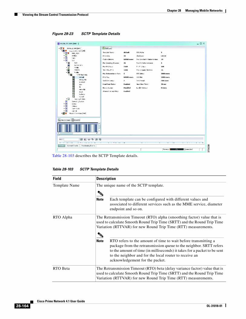
Chapter 28 Managing Mobile Networks Viewing the Stream Control Transmission Protocol
Figure 28-23 SCTP Template Details
Table 28-103 describes the SCTP Template details.
Table 28-103 SCTP Template Details
Field Description
Template Name The unique name of the SCTP template.
Note Each template can be configured with different values and associated to different services such as the MME service, diameter endpoint and so on.
RTO Alpha The Retransmission Timeout (RTO) alpha (smoothing factor) value that is used to calculate Smooth Round Trip Time (SRTT) and the Round Trip Time Variation (RTTVAR) for new Round Trip Time (RTT) measurements.
Note RTO refers to the amount of time to wait before transmitting a package from the retransmission queue to the neighbor. SRTT refers to the amount of time (in milliseconds) it takes for a packet to be sent to the neighbor and for the local router to receive an acknowledgement for the packet.
RTO Beta The Retransmission Timeout (RTO) beta (delay variance factor) value that is used to calculate Smooth Round Trip Time (SRTT) and the Round Trip Time Variation (RTTVAR) for new Round Trip Time (RTT) measurements.
28-164Cisco Prime Network 4.1 User Guide
OL-31018-01

Chapter 28 Managing Mobile Networks Viewing the Stream Control Transmission Protocol
Checksum The type of checksum that is used to increase data integrity of the SCTP packets, which can be any one of the following:
• adler32—the Adler-32 checksum algorithm is used
• crc32—the 32 bit cyclic redundancy check algorithm is used.
Cookie Lifetime The lifetime (in milliseconds) of the SCTP cookie.
Max Association Retransmission
The maximum number of retransmissions allowed by this template for the SCTP associations.
Max Incoming Streams The maximum number of incoming SCTP streams.
Max Init Retransmissions
The maximum number of SCTP initiation retransmissions.
Max MTU Size The maximum size (in bytes) of the Maximum Transmission Unit (MTU) for SCTP streams.
Min MTU Size The minimum size (in bytes) of the MTU for SCTP streams.
Start Max MTU The starting size (in bytes) of the MTU for SCTP streams.
Max Outgoing Streams The maximum number of outgoing SCTP streams.
Max Retransmissions Path
The maximum number of retransmissions of the SCTP paths.
RTO Initial The initial time (in milliseconds) for retransmission of SCTP packets.
RTO Max The maximum time (in miliseconds) for retransmission of SCTP packets.
RTO Min The minimum time (in milliseconds) for transmission of SCTP packets.
SACK Frequency The frequency of the Selective Acknowledgement (SACK) of the SCTP packets.
SACK Period The period (in milliseconds) of selective acknowledgement of the SCTP packets.
Heart Beat Status Indicates whether the option to send traffic over an alternate path, in case of a path failure, is enabled.
Note The Heartbeat message is sent to a peer endpoint to probe the reachability of a particular destination transport address defined in the present association. If the address is not reachable, the traffic is sent over an alternate address. If this option is enabled, then the failover recovery is not even known to the user.
Heart Beat Timer The amount of time (in seconds) to wait before a peer is is considered unreachable. When a Heartbeat request is sent and if an acknowledgement is not received before this timer, then subsequent heartbeat requests are not sent and the peer is considered unreachable.
Bundle Status Indicates whether the data chunks must be bundled into packets before submitting to the IP. If this option is disabled, then the packets are sent without bundling.
Table 28-103 SCTP Template Details (continued)
Field Description
28-165Cisco Prime Network 4.1 User Guide
OL-31018-01

Chapter 28 Managing Mobile Networks Viewing the Stream Control Transmission Protocol
Bundle Timeout The amount of time (in seconds) after which the chunks of SCTP packets are bundled and committed for transmission.
Alternate Accept Flag Indicates whether the alternate accept flag that denotes additional lifetime for the association, is enabled.
Table 28-103 SCTP Template Details (continued)
Field Description
28-166Cisco Prime Network 4.1 User Guide
OL-31018-01