Embed Size (px)
Citation preview
Managing Network Adapters
This chapter includes the following sections:
• Overview of the Cisco UCS C-Series Network Adapters, page 1
• Viewing Network Adapter Properties, page 4
• Configuring Network Adapter Properties, page 5
• Managing vHBAs, page 6
• Managing vNICs, page 18
• Managing VM FEX, page 37
• Backing Up and Restoring the Adapter Configuration, page 42
• Managing Adapter Firmware, page 45
Overview of the Cisco UCS C-Series Network Adapters
The procedures in this chapter are available only when a Cisco UCS C-Series network adapter is installedin the chassis.
Note
A Cisco UCS C-Series network adapter can be installed to provide options for I/O consolidation andvirtualization support. The following adapters are available:
• Cisco UCS P81E Virtual Interface Card
• Cisco UCS VIC 1225 Virtual Interface Card
• Cisco UCS VIC 1385 Virtual Interface Card
• Cisco UCS VIC 1227T Virtual Interface Card
• Cisco UCS VIC 1387 Virtual Interface Card
The interactiveUCS Hardware and Software Interoperability Utility lets you view the supported componentsand configurations for a selected server model and software release. The utility is available at the followingURL: http://www.cisco.com/web/techdoc/ucs/interoperability/matrix/matrix.html
Cisco UCS C-Series Integrated Management Controller CLI Configuration Guide for C3X60 Servers 1
Cisco UCS P81E Virtual Interface Card
The Cisco UCS P81E Virtual Interface Card is optimized for virtualized environments, for organizations thatseek increased mobility in their physical environments, and for data centers that want reduced costs throughNIC, HBA, cabling, and switch reduction and reducedmanagement overhead. This Fibre Channel over Ethernet(FCoE) PCIe card offers the following benefits:
• Allows up to 16 virtual Fibre Channel and 16 virtual Ethernet adapters to be provisioned in virtualizedor nonvirtualized environments using just-in-time provisioning, providing tremendous system flexibilityand allowing consolidation of multiple physical adapters.
• Delivers uncompromising virtualization support, including hardware-based implementation of CiscoVN-Link technology and pass-through switching.
• Improves system security and manageability by providing visibility and portability of network policesand security all the way to the virtual machine.
The virtual interface card makes Cisco VN-Link connections to the parent fabric interconnects, which allowsvirtual links to connect virtual NICs in virtual machines to virtual interfaces in the interconnect. In a CiscoUnified Computing System environment, virtual links then can be managed, network profiles applied, andinterfaces dynamically reprovisioned as virtual machines move between servers in the system.
Cisco UCS VIC 1225 Virtual Interface Card
The Cisco UCS VIC 1225 Virtual Interface Card is a high-performance, converged network adapter thatprovides acceleration for the various new operational modes introduced by server virtualization. It bringssuperior flexibility, performance, and bandwidth to the new generation of Cisco UCS C-Series Rack-MountServers.
The Cisco UCS VIC 1225 implements the Cisco Virtual Machine Fabric Extender (VM-FEX), which unifiesvirtual and physical networking into a single infrastructure. It provides virtual-machine visibility from thephysical network and a consistent network operations model for physical and virtual servers. In virtualizedenvironments, this highly configurable and self-virtualized adapter provides integrated, modular LAN interfaceson Cisco UCS C-Series Rack-Mount Servers. Additional features and capabilities include:
• Supports up to 256 PCIe virtual devices, either virtual network interface cards (vNICs) or virtual hostbus adapters (vHBAs), with high I/O operations per second (IOPS), support for lossless Ethernet, and20 Gbps to servers.
• PCIe Gen2 x16 helps assure optimal bandwidth to the host for network-intensive applications with aredundant path to the fabric interconnect.
• Half-height design reserves full-height slots in servers for Cisco certified third-party adapters.
• Centrally managed by Cisco UCS Manager with support for Microsoft Windows, Red Hat EnterpriseLinux, SUSE Linux, VMware vSphere, and Citrix XenServer.
Cisco UCS VIC 1385 Virtual Interface Card
The Cisco UCS VIC 1385 Virtual Interface Cardis a dual-port Enhanced Quad Small Form-Factor Pluggable(QSFP) 40 Gigabit Ethernet and Fibre Channel over Ethernet (FCoE)-capable half-height PCI Express (PCIe)card designed exclusively for Cisco UCS C-Series Rack Servers. It incorporates Cisco’s next-generationconverged network adapter (CNA) technology, with a comprehensive feature set, providing investmentprotection for future feature software releases. The card enables a policy-based, stateless, agile serverinfrastructure that can present over 256 PCIe standards-compliant interfaces to the host that can be dynamicallyconfigured as either network interface cards (NICs) or host bus adapters (HBAs). In addition, the Cisco UCS
Cisco UCS C-Series Integrated Management Controller CLI Configuration Guide for C3X60 Servers2
Managing Network AdaptersOverview of the Cisco UCS C-Series Network Adapters
VIC 1385 card supports Cisco Data Center Virtual Machine Fabric Extender (VM-FEX) technology, whichextends the Cisco UCS fabric interconnect ports to virtual machines, simplifying server virtualizationdeployment.
The personality of the card is determined dynamically at boot time using the service profile associated withthe server. The number, type (NIC or HBA), identity (MAC address andWorldWide Name [WWN]), failoverpolicy, bandwidth, and quality-of-service (QoS) policies of the PCIe interfaces are all determined using theservice profile. The capability to define, create, and use interfaces on demand provides a stateless and agileserver infrastructure. Additional features and capabilities include:
• Each PCIe interface created on the VIC is associated with an interface on the Cisco UCS fabricinterconnect, providing complete network separation for each virtual cable between a PCIe device onthe VIC and the interface on the fabric interconnect
• The Cisco UCS VIC 1385 Virtual Interface Card provides high network performance and low latencyfor the most demanding applications such as SMB-Direct, VMQ, DPDK, and Cisco NetFlow
Cisco UCS VIC 1227T Virtual Interface Card
The Cisco UCS VIC 1227T Virtual Interface Card is a dual-port 10GBASE-T (RJ-45) 10-Gbps Ethernet andFibre Channel over Ethernet (FCoE)–capable PCI Express (PCIe) modular LAN-on-motherboard (mLOM)adapter designed exclusively for Cisco UCS C-Series Rack Servers. New to Cisco rack servers, the mLOMslot can be used to install a Cisco VICwithout consuming a PCIe slot, which provides greater I/O expandability.It incorporates next-generation converged network adapter (CNA) technology from Cisco, providing FibreChannel connectivity over low-cost twisted pair cabling with a bit error rate (BER) of 10 to 15 up to 30 metersand investment protection for future feature releases. The mLOM card enables a policy-based, stateless, agileserver infrastructure that can present up to 256 PCIe standards-compliant interfaces to the host that can bedynamically configured as either network interface cards (NICs) or host bus adapters (HBAs). In addition,the Cisco UCSVIC 1227TVirtual Interface Card supports Cisco Data Center Virtual Machine Fabric Extender(VM-FEX) technology, which extends the Cisco UCS fabric interconnect ports to virtual machines, simplifyingserver virtualization deployment. Additional features and capabilities include:
• Stateless and agile design - The personality of the card is determined dynamically at boot time using theservice profile associated with the server. The number, type (NIC or HBA), identity (MAC address andWorld Wide Name [WWN]), failover policy, bandwidth, and quality-of-service (QoS) policies of thePCIe interfaces are all determined using the service profile. The capability to define, create, and useinterfaces on demand provides a stateless and agile server infrastructure.
• Each PCIe interface created on the VIC is associated with an interface on the Cisco UCS fabricinterconnect, providing complete network separation for each virtual cable between a PCIe device onthe VIC and the interface on the fabric interconnect.
• Cisco SingleConnect technology provides an exceptionally easy, intelligent, and efficient way to connectand manage computing in the data center. Cisco SingleConnect technology dramatically simplifies theway that data centers connect to rack and blade servers, physical servers, virtual machines, LANs, SANs,and management networks.
Cisco UCS VIC 1387 Virtual Interface Card
The Cisco UCS VIC 1387 Virtual Interface Card is a dual-port Enhanced Quad Small Form-Factor Pluggable(QSFP) 40 Gigabit Ethernet and Fibre Channel over Ethernet (FCoE)-capable half-height PCI Express (PCIe)card designed exclusively for Cisco UCS C-Series Rack Servers. It incorporates Cisco’s next-generationconverged network adapter (CNA) technology, with a comprehensive feature set, providing investmentprotection for future feature software releases. The card enables a policy-based, stateless, agile server
Cisco UCS C-Series Integrated Management Controller CLI Configuration Guide for C3X60 Servers 3
Managing Network AdaptersOverview of the Cisco UCS C-Series Network Adapters

infrastructure that can present over 256 PCIe standards-compliant interfaces to the host that can be dynamicallyconfigured as either network interface cards (NICs) or host bus adapters (HBAs). In addition, the Cisco UCSVIC 1387 card supports Cisco Data Center Virtual Machine Fabric Extender (VM-FEX) technology, whichextends the Cisco UCS fabric interconnect ports to virtual machines, simplifying server virtualizationdeployment.
The personality of the card is determined dynamically at boot time using the service profile associated withthe server. The number, type (NIC or HBA), identity (MAC address andWorldWide Name [WWN]), failoverpolicy, bandwidth, and quality-of-service (QoS) policies of the PCIe interfaces are all determined using theservice profile. The capability to define, create, and use interfaces on demand provides a stateless and agileserver infrastructure. Additional features and capabilities include:
• Each PCIe interface created on the VIC is associated with an interface on the Cisco UCS fabricinterconnect, providing complete network separation for each virtual cable between a PCIe device onthe VIC and the interface on the fabric interconnect
• The Cisco UCS VIC 1387 Virtual Interface Card provides high network performance and low latencyfor the most demanding applications such as SMB-Direct, VMQ, DPDK, and Cisco NetFlow
Viewing Network Adapter PropertiesProcedure
PurposeCommand or Action
Enters the chassis command mode.Server# scope chassisStep 1
Displays adapter properties. To display the propertiesof a single adapter, specify the PCI slot number as theindex argument.
Server /chassis # show adapter[index] [detail]
Step 2
This example displays the properties of adapter 2:Server# scope chassisServer /chassis # show adapterPCI Slot Product Name Serial Number Product ID Vendor-------- -------------- -------------- -------------- --------------------1 UCS VIC 1225 FCH1613796C UCSC-PCIE-C... Cisco Systems Inc
Server /chassis # show adapter 2 detailPCI Slot 2:
Product Name: UCS VIC 1225Serial Number: FCH1613796CProduct ID: UCSC-PCIE-CSC-02Adapter Hardware Revision: 4Current FW Version: 2.1(0.291)NIV: DisabledFIP: EnabledConfiguration Pending: noCIMC Management Enabled : noVID: V00Vendor: Cisco Systems IncDescription:Bootloader Version: 2.1(0.291)FW Image 1 Version: 2.1(0.291)FW Image 1 State: RUNNING ACTIVATEDFW Image 2 Version: 1.6(0.547)
Cisco UCS C-Series Integrated Management Controller CLI Configuration Guide for C3X60 Servers4
Managing Network AdaptersViewing Network Adapter Properties
FW Image 2 State: BACKUP INACTIVATEDFW Update Status: IdleFW Update Error: No errorFW Update Stage: No operation (0%)FW Update Overall Progress: 0%
Server /chassis #
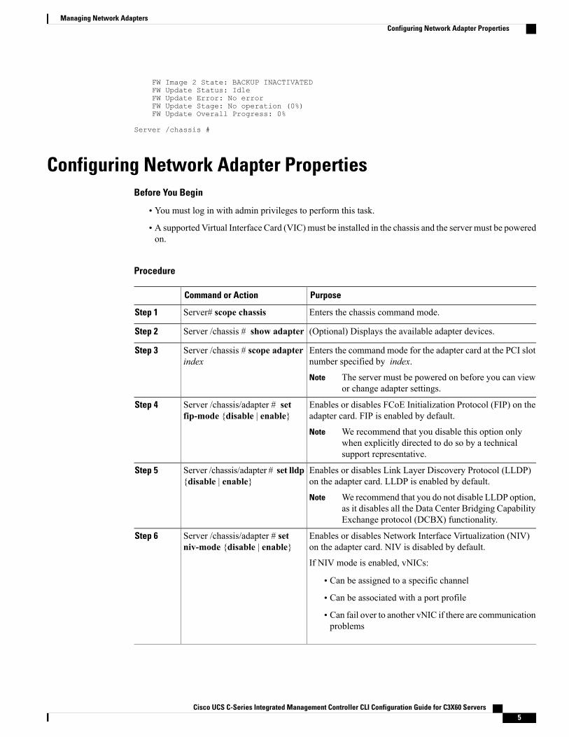
Configuring Network Adapter PropertiesBefore You Begin
• You must log in with admin privileges to perform this task.
• A supported Virtual Interface Card (VIC) must be installed in the chassis and the server must be poweredon.
Procedure
PurposeCommand or Action
Enters the chassis command mode.Server# scope chassisStep 1
(Optional) Displays the available adapter devices.Server /chassis # show adapterStep 2
Enters the command mode for the adapter card at the PCI slotnumber specified by index.
Server /chassis # scope adapterindex
Step 3
The server must be powered on before you can viewor change adapter settings.
Note
Enables or disables FCoE Initialization Protocol (FIP) on theadapter card. FIP is enabled by default.
Server /chassis/adapter # setfip-mode {disable | enable}
Step 4
We recommend that you disable this option onlywhen explicitly directed to do so by a technicalsupport representative.
Note
Enables or disables Link Layer Discovery Protocol (LLDP)on the adapter card. LLDP is enabled by default.
Server /chassis/adapter # set lldp{disable | enable}
Step 5
We recommend that you do not disable LLDP option,as it disables all the Data Center Bridging CapabilityExchange protocol (DCBX) functionality.
Note
Enables or disables Network Interface Virtualization (NIV)on the adapter card. NIV is disabled by default.
Server /chassis/adapter # setniv-mode {disable | enable}
Step 6
If NIV mode is enabled, vNICs:
• Can be assigned to a specific channel
• Can be associated with a port profile
• Can fail over to another vNIC if there are communicationproblems
Cisco UCS C-Series Integrated Management Controller CLI Configuration Guide for C3X60 Servers 5
Managing Network AdaptersConfiguring Network Adapter Properties
PurposeCommand or Action
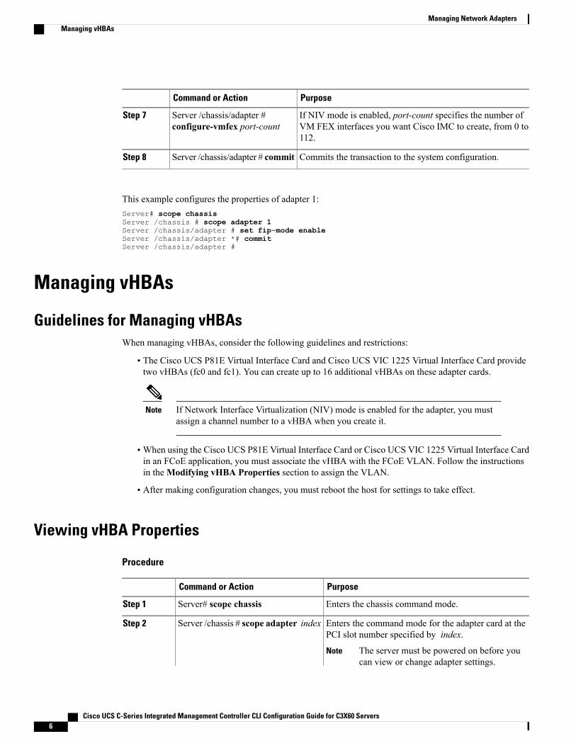
If NIV mode is enabled, port-count specifies the number ofVM FEX interfaces you want Cisco IMC to create, from 0 to112.
Server /chassis/adapter #configure-vmfex port-count
Step 7
Commits the transaction to the system configuration.Server /chassis/adapter # commitStep 8
This example configures the properties of adapter 1:Server# scope chassisServer /chassis # scope adapter 1Server /chassis/adapter # set fip-mode enableServer /chassis/adapter *# commitServer /chassis/adapter #
Managing vHBAs
Guidelines for Managing vHBAsWhen managing vHBAs, consider the following guidelines and restrictions:
• The Cisco UCS P81E Virtual Interface Card and Cisco UCS VIC 1225 Virtual Interface Card providetwo vHBAs (fc0 and fc1). You can create up to 16 additional vHBAs on these adapter cards.
If Network Interface Virtualization (NIV) mode is enabled for the adapter, you mustassign a channel number to a vHBA when you create it.
Note
•When using the Cisco UCS P81E Virtual Interface Card or Cisco UCS VIC 1225 Virtual Interface Cardin an FCoE application, you must associate the vHBA with the FCoE VLAN. Follow the instructionsin theModifying vHBA Properties section to assign the VLAN.
• After making configuration changes, you must reboot the host for settings to take effect.
Viewing vHBA Properties
Procedure
PurposeCommand or Action
Enters the chassis command mode.Server# scope chassisStep 1
Enters the command mode for the adapter card at thePCI slot number specified by index.
Server /chassis # scope adapter indexStep 2
The server must be powered on before youcan view or change adapter settings.
Note
Cisco UCS C-Series Integrated Management Controller CLI Configuration Guide for C3X60 Servers6
Managing Network AdaptersManaging vHBAs
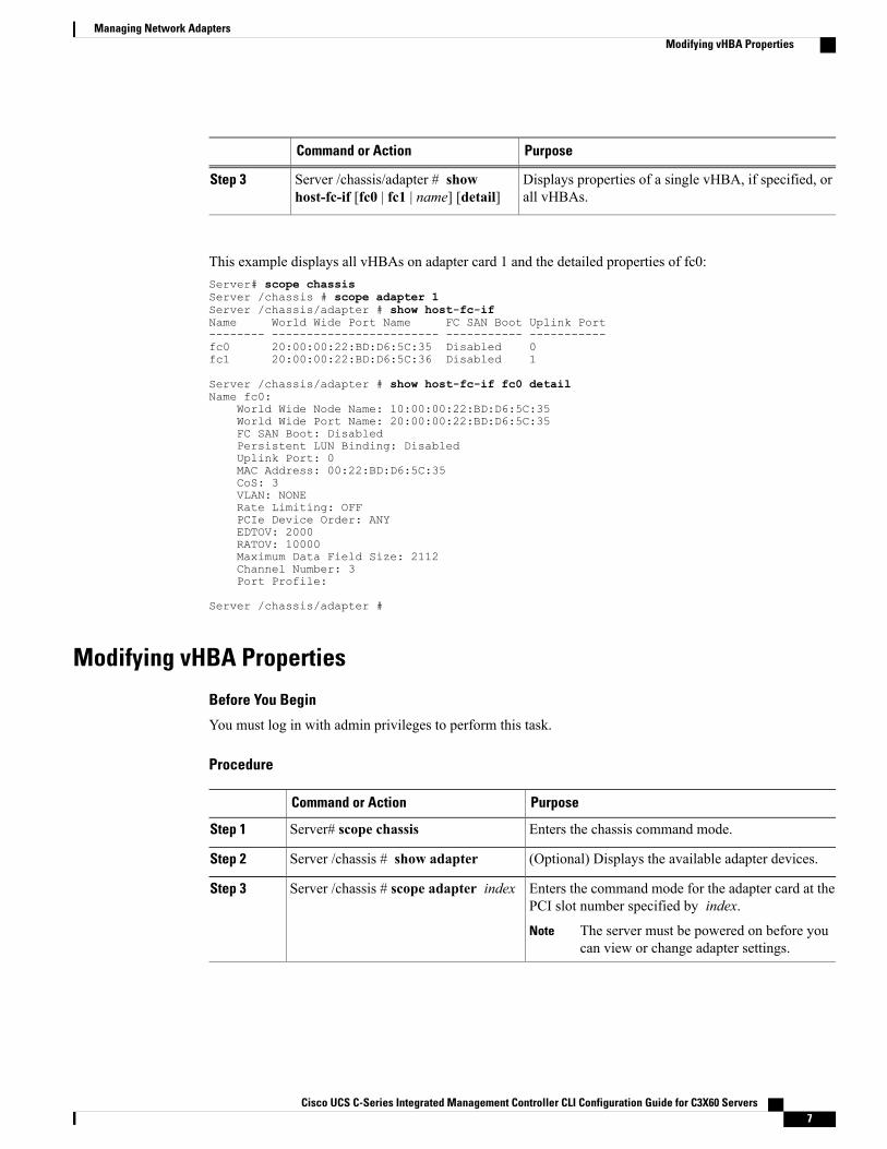
PurposeCommand or Action
Displays properties of a single vHBA, if specified, orall vHBAs.
Server /chassis/adapter # showhost-fc-if [fc0 | fc1 | name] [detail]
Step 3
This example displays all vHBAs on adapter card 1 and the detailed properties of fc0:Server# scope chassisServer /chassis # scope adapter 1Server /chassis/adapter # show host-fc-ifName World Wide Port Name FC SAN Boot Uplink Port-------- ------------------------ ----------- -----------fc0 20:00:00:22:BD:D6:5C:35 Disabled 0fc1 20:00:00:22:BD:D6:5C:36 Disabled 1
Server /chassis/adapter # show host-fc-if fc0 detailName fc0:
World Wide Node Name: 10:00:00:22:BD:D6:5C:35World Wide Port Name: 20:00:00:22:BD:D6:5C:35FC SAN Boot: DisabledPersistent LUN Binding: DisabledUplink Port: 0MAC Address: 00:22:BD:D6:5C:35CoS: 3VLAN: NONERate Limiting: OFFPCIe Device Order: ANYEDTOV: 2000RATOV: 10000Maximum Data Field Size: 2112Channel Number: 3Port Profile:
Server /chassis/adapter #
Modifying vHBA Properties
Before You Begin
You must log in with admin privileges to perform this task.
Procedure
PurposeCommand or Action
Enters the chassis command mode.Server# scope chassisStep 1
(Optional) Displays the available adapter devices.Server /chassis # show adapterStep 2
Enters the command mode for the adapter card at thePCI slot number specified by index.
Server /chassis # scope adapter indexStep 3
The server must be powered on before youcan view or change adapter settings.
Note
Cisco UCS C-Series Integrated Management Controller CLI Configuration Guide for C3X60 Servers 7
Managing Network AdaptersModifying vHBA Properties
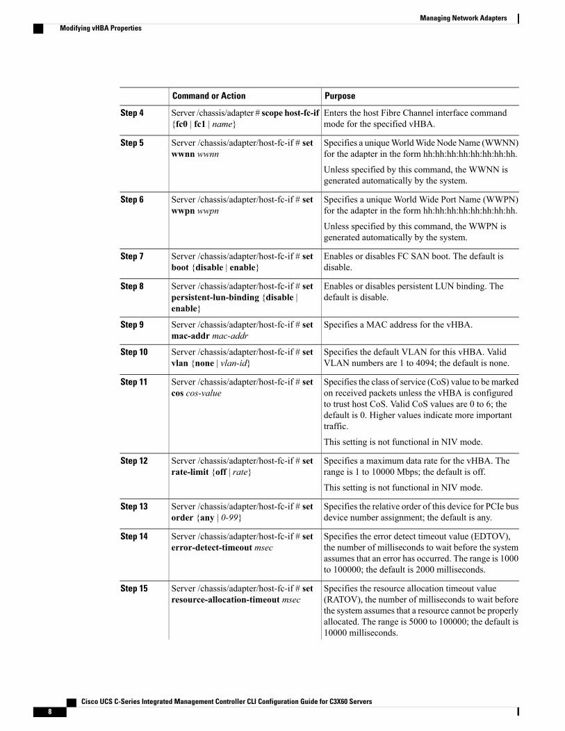
PurposeCommand or Action
Enters the host Fibre Channel interface commandmode for the specified vHBA.
Server /chassis/adapter # scope host-fc-if{fc0 | fc1 | name}
Step 4
Specifies a uniqueWorldWide Node Name (WWNN)for the adapter in the form hh:hh:hh:hh:hh:hh:hh:hh.
Server /chassis/adapter/host-fc-if # setwwnn wwnn
Step 5
Unless specified by this command, the WWNN isgenerated automatically by the system.
Specifies a unique World Wide Port Name (WWPN)for the adapter in the form hh:hh:hh:hh:hh:hh:hh:hh.
Server /chassis/adapter/host-fc-if # setwwpn wwpn
Step 6
Unless specified by this command, the WWPN isgenerated automatically by the system.
Enables or disables FC SAN boot. The default isdisable.
Server /chassis/adapter/host-fc-if # setboot {disable | enable}
Step 7
Enables or disables persistent LUN binding. Thedefault is disable.
Server /chassis/adapter/host-fc-if # setpersistent-lun-binding {disable |enable}
Step 8
Specifies a MAC address for the vHBA.Server /chassis/adapter/host-fc-if # setmac-addr mac-addr
Step 9
Specifies the default VLAN for this vHBA. ValidVLAN numbers are 1 to 4094; the default is none.
Server /chassis/adapter/host-fc-if # setvlan {none | vlan-id}
Step 10
Specifies the class of service (CoS) value to bemarkedon received packets unless the vHBA is configured
Server /chassis/adapter/host-fc-if # setcos cos-value
Step 11
to trust host CoS. Valid CoS values are 0 to 6; thedefault is 0. Higher values indicate more importanttraffic.
This setting is not functional in NIV mode.
Specifies a maximum data rate for the vHBA. Therange is 1 to 10000 Mbps; the default is off.
Server /chassis/adapter/host-fc-if # setrate-limit {off | rate}
Step 12
This setting is not functional in NIV mode.
Specifies the relative order of this device for PCIe busdevice number assignment; the default is any.
Server /chassis/adapter/host-fc-if # setorder {any | 0-99}
Step 13
Specifies the error detect timeout value (EDTOV),the number of milliseconds to wait before the system
Server /chassis/adapter/host-fc-if # seterror-detect-timeout msec
Step 14
assumes that an error has occurred. The range is 1000to 100000; the default is 2000 milliseconds.
Specifies the resource allocation timeout value(RATOV), the number of milliseconds to wait before
Server /chassis/adapter/host-fc-if # setresource-allocation-timeout msec
Step 15
the system assumes that a resource cannot be properlyallocated. The range is 5000 to 100000; the default is10000 milliseconds.
Cisco UCS C-Series Integrated Management Controller CLI Configuration Guide for C3X60 Servers8
Managing Network AdaptersModifying vHBA Properties

PurposeCommand or Action
Specifies the maximum size of the Fibre Channelframe payload (in bytes) that the vHBA supports. Therange is 1 to 2112; the default is 2112 bytes.
Server /chassis/adapter/host-fc-if # setmax-field-size size
Step 16
Enters the Fibre Channel error recovery commandmode.
Server /chassis/adapter/host-fc-if # scopeerror-recovery
Step 17
Enables or disables FCP Error Recovery. The defaultis disable.
Server/chassis/adapter/host-fc-if/error-recovery# set fcp-error-recovery {disable |enable}
Step 18
Specifies the link down timeout value, the number ofmilliseconds the uplink port should be offline before
Server/chassis/adapter/host-fc-if/error-recovery# set link-down-timeout msec
Step 19
it informs the system that the uplink port is down andfabric connectivity has been lost. The range is 0 to240000; the default is 30000 milliseconds.
Specifies the port down I/O retries value, the numberof times an I/O request to a port is returned because
Server/chassis/adapter/host-fc-if/error-recovery# set port-down-io-retry-count count
Step 20
the port is busy before the system decides the port isunavailable. The range is 0 to 255; the default is 8retries.
Specifies the port down timeout value, the number ofmilliseconds a remote Fibre Channel port should be
Server/chassis/adapter/host-fc-if/error-recovery# set port-down-timeout msec
Step 21
offline before informing the SCSI upper layer that theport is unavailable. The range is 0 to 240000; thedefault is 10000 milliseconds.
Exits to the host Fibre Channel interface commandmode.
Server/chassis/adapter/host-fc-if/error-recovery# exit
Step 22
Enters the interrupt command mode.Server /chassis/adapter/host-fc-if # scopeinterrupt
Step 23
Specifies the Fibre Channel interrupt mode. Themodes are as follows:
Server/chassis/adapter/host-fc-if/interrupt # setinterrupt-mode {intx |msi |msix}
Step 24
• intx—Line-based interrupt (INTx)
• msi—Message-Signaled Interrupt (MSI)
• msix—Message Signaled Interrupts with theoptional extension (MSIx). This is therecommended and default option.
Exits to the host Fibre Channel interface commandmode.
Server/chassis/adapter/host-fc-if/interrupt # exit
Step 25
Cisco UCS C-Series Integrated Management Controller CLI Configuration Guide for C3X60 Servers 9
Managing Network AdaptersModifying vHBA Properties
PurposeCommand or Action
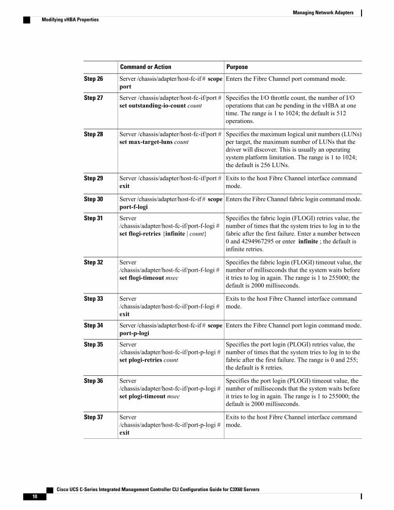
Enters the Fibre Channel port command mode.Server /chassis/adapter/host-fc-if # scopeport
Step 26
Specifies the I/O throttle count, the number of I/Ooperations that can be pending in the vHBA at one
Server /chassis/adapter/host-fc-if/port #set outstanding-io-count count
Step 27
time. The range is 1 to 1024; the default is 512operations.
Specifies the maximum logical unit numbers (LUNs)per target, the maximum number of LUNs that the
Server /chassis/adapter/host-fc-if/port #set max-target-luns count
Step 28
driver will discover. This is usually an operatingsystem platform limitation. The range is 1 to 1024;the default is 256 LUNs.
Exits to the host Fibre Channel interface commandmode.
Server /chassis/adapter/host-fc-if/port #exit
Step 29
Enters the Fibre Channel fabric login commandmode.Server /chassis/adapter/host-fc-if # scopeport-f-logi
Step 30
Specifies the fabric login (FLOGI) retries value, thenumber of times that the system tries to log in to the
Server/chassis/adapter/host-fc-if/port-f-logi #set flogi-retries {infinite | count}
Step 31
fabric after the first failure. Enter a number between0 and 4294967295 or enter infinite ; the default isinfinite retries.
Specifies the fabric login (FLOGI) timeout value, thenumber of milliseconds that the system waits before
Server/chassis/adapter/host-fc-if/port-f-logi #set flogi-timeout msec
Step 32
it tries to log in again. The range is 1 to 255000; thedefault is 2000 milliseconds.
Exits to the host Fibre Channel interface commandmode.
Server/chassis/adapter/host-fc-if/port-f-logi #exit
Step 33
Enters the Fibre Channel port login command mode.Server /chassis/adapter/host-fc-if # scopeport-p-logi
Step 34
Specifies the port login (PLOGI) retries value, thenumber of times that the system tries to log in to the
Server/chassis/adapter/host-fc-if/port-p-logi #set plogi-retries count
Step 35
fabric after the first failure. The range is 0 and 255;the default is 8 retries.
Specifies the port login (PLOGI) timeout value, thenumber of milliseconds that the system waits before
Server/chassis/adapter/host-fc-if/port-p-logi #set plogi-timeout msec
Step 36
it tries to log in again. The range is 1 to 255000; thedefault is 2000 milliseconds.
Exits to the host Fibre Channel interface commandmode.
Server/chassis/adapter/host-fc-if/port-p-logi #exit
Step 37
Cisco UCS C-Series Integrated Management Controller CLI Configuration Guide for C3X60 Servers10
Managing Network AdaptersModifying vHBA Properties
PurposeCommand or Action
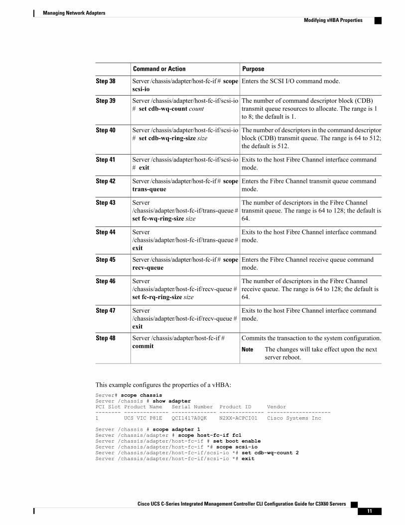
Enters the SCSI I/O command mode.Server /chassis/adapter/host-fc-if # scopescsi-io
Step 38
The number of command descriptor block (CDB)transmit queue resources to allocate. The range is 1to 8; the default is 1.
Server /chassis/adapter/host-fc-if/scsi-io# set cdb-wq-count count
Step 39
The number of descriptors in the command descriptorblock (CDB) transmit queue. The range is 64 to 512;the default is 512.
Server /chassis/adapter/host-fc-if/scsi-io# set cdb-wq-ring-size size
Step 40
Exits to the host Fibre Channel interface commandmode.
Server /chassis/adapter/host-fc-if/scsi-io# exit
Step 41
Enters the Fibre Channel transmit queue commandmode.
Server /chassis/adapter/host-fc-if # scopetrans-queue
Step 42
The number of descriptors in the Fibre Channeltransmit queue. The range is 64 to 128; the default is64.
Server/chassis/adapter/host-fc-if/trans-queue #set fc-wq-ring-size size
Step 43
Exits to the host Fibre Channel interface commandmode.
Server/chassis/adapter/host-fc-if/trans-queue #exit
Step 44
Enters the Fibre Channel receive queue commandmode.
Server /chassis/adapter/host-fc-if # scoperecv-queue
Step 45
The number of descriptors in the Fibre Channelreceive queue. The range is 64 to 128; the default is64.
Server/chassis/adapter/host-fc-if/recv-queue #set fc-rq-ring-size size
Step 46
Exits to the host Fibre Channel interface commandmode.
Server/chassis/adapter/host-fc-if/recv-queue #exit
Step 47
Commits the transaction to the system configuration.Server /chassis/adapter/host-fc-if #commit
Step 48
The changes will take effect upon the nextserver reboot.
Note
This example configures the properties of a vHBA:Server# scope chassisServer /chassis # show adapterPCI Slot Product Name Serial Number Product ID Vendor-------- -------------- -------------- -------------- --------------------1 UCS VIC P81E QCI1417A0QK N2XX-ACPCI01 Cisco Systems Inc
Server /chassis # scope adapter 1Server /chassis/adapter # scope host-fc-if fc1Server /chassis/adapter/host-fc-if # set boot enableServer /chassis/adapter/host-fc-if *# scope scsi-ioServer /chassis/adapter/host-fc-if/scsi-io *# set cdb-wq-count 2Server /chassis/adapter/host-fc-if/scsi-io *# exit
Cisco UCS C-Series Integrated Management Controller CLI Configuration Guide for C3X60 Servers 11
Managing Network AdaptersModifying vHBA Properties
Server /chassis/adapter/host-fc-if *# commitServer /chassis/adapter/host-fc-if #
What to Do Next
Reboot the server to apply the changes.
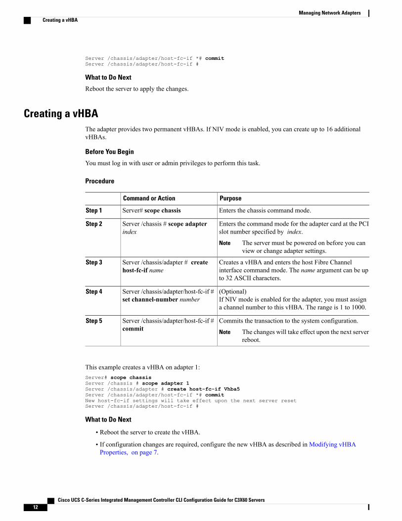
Creating a vHBAThe adapter provides two permanent vHBAs. If NIV mode is enabled, you can create up to 16 additionalvHBAs.
Before You Begin
You must log in with user or admin privileges to perform this task.
Procedure
PurposeCommand or Action
Enters the chassis command mode.Server# scope chassisStep 1
Enters the command mode for the adapter card at the PCIslot number specified by index.
Server /chassis # scope adapterindex
Step 2
The server must be powered on before you canview or change adapter settings.
Note
Creates a vHBA and enters the host Fibre Channelinterface command mode. The name argument can be upto 32 ASCII characters.
Server /chassis/adapter # createhost-fc-if name
Step 3
(Optional)If NIV mode is enabled for the adapter, you must assigna channel number to this vHBA. The range is 1 to 1000.
Server /chassis/adapter/host-fc-if #set channel-number number
Step 4
Commits the transaction to the system configuration.Server /chassis/adapter/host-fc-if #commit
Step 5
The changes will take effect upon the next serverreboot.
Note
This example creates a vHBA on adapter 1:Server# scope chassisServer /chassis # scope adapter 1Server /chassis/adapter # create host-fc-if Vhba5Server /chassis/adapter/host-fc-if *# commitNew host-fc-if settings will take effect upon the next server resetServer /chassis/adapter/host-fc-if #
What to Do Next
• Reboot the server to create the vHBA.
• If configuration changes are required, configure the new vHBA as described in Modifying vHBAProperties, on page 7.
Cisco UCS C-Series Integrated Management Controller CLI Configuration Guide for C3X60 Servers12
Managing Network AdaptersCreating a vHBA
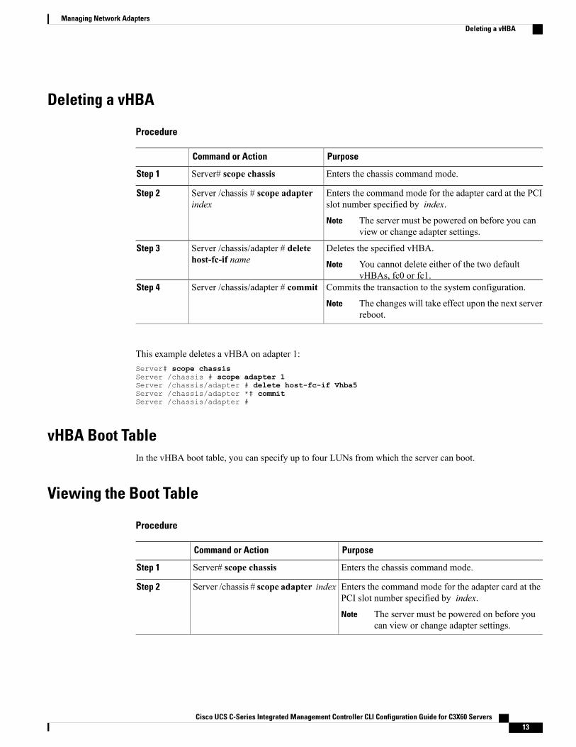
Deleting a vHBA
Procedure
PurposeCommand or Action
Enters the chassis command mode.Server# scope chassisStep 1
Enters the command mode for the adapter card at the PCIslot number specified by index.
Server /chassis # scope adapterindex
Step 2
The server must be powered on before you canview or change adapter settings.
Note
Deletes the specified vHBA.Server /chassis/adapter # deletehost-fc-if name
Step 3
You cannot delete either of the two defaultvHBAs, fc0 or fc1.
Note
Commits the transaction to the system configuration.Server /chassis/adapter # commitStep 4
The changes will take effect upon the next serverreboot.
Note
This example deletes a vHBA on adapter 1:Server# scope chassisServer /chassis # scope adapter 1Server /chassis/adapter # delete host-fc-if Vhba5Server /chassis/adapter *# commitServer /chassis/adapter #
vHBA Boot TableIn the vHBA boot table, you can specify up to four LUNs from which the server can boot.
Viewing the Boot Table
Procedure
PurposeCommand or Action
Enters the chassis command mode.Server# scope chassisStep 1
Enters the command mode for the adapter card at thePCI slot number specified by index.
Server /chassis # scope adapter indexStep 2
The server must be powered on before youcan view or change adapter settings.
Note
Cisco UCS C-Series Integrated Management Controller CLI Configuration Guide for C3X60 Servers 13
Managing Network AdaptersDeleting a vHBA
PurposeCommand or Action
Enters the host Fibre Channel interface commandmodefor the specified vHBA.
Server /chassis/adapter # scopehost-fc-if {fc0 | fc1 | name}
Step 3
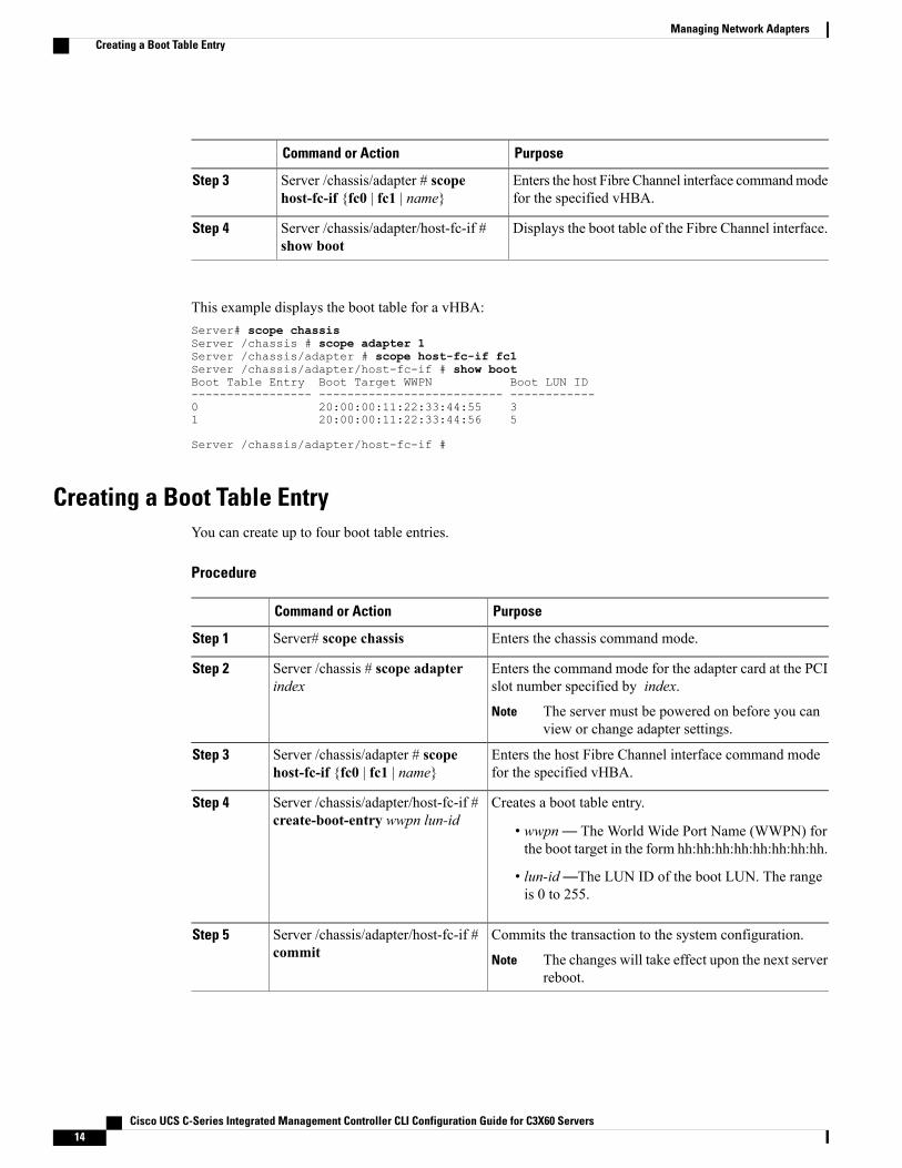
Displays the boot table of the Fibre Channel interface.Server /chassis/adapter/host-fc-if #show boot
Step 4
This example displays the boot table for a vHBA:Server# scope chassisServer /chassis # scope adapter 1Server /chassis/adapter # scope host-fc-if fc1Server /chassis/adapter/host-fc-if # show bootBoot Table Entry Boot Target WWPN Boot LUN ID----------------- -------------------------- ------------0 20:00:00:11:22:33:44:55 31 20:00:00:11:22:33:44:56 5
Server /chassis/adapter/host-fc-if #
Creating a Boot Table EntryYou can create up to four boot table entries.
Procedure
PurposeCommand or Action
Enters the chassis command mode.Server# scope chassisStep 1
Enters the command mode for the adapter card at the PCIslot number specified by index.
Server /chassis # scope adapterindex
Step 2
The server must be powered on before you canview or change adapter settings.
Note
Enters the host Fibre Channel interface command modefor the specified vHBA.
Server /chassis/adapter # scopehost-fc-if {fc0 | fc1 | name}
Step 3
Creates a boot table entry.Server /chassis/adapter/host-fc-if #create-boot-entry wwpn lun-id
Step 4
• wwpn— The World Wide Port Name (WWPN) forthe boot target in the form hh:hh:hh:hh:hh:hh:hh:hh.
• lun-id—The LUN ID of the boot LUN. The rangeis 0 to 255.
Commits the transaction to the system configuration.Server /chassis/adapter/host-fc-if #commit
Step 5
The changes will take effect upon the next serverreboot.
Note
Cisco UCS C-Series Integrated Management Controller CLI Configuration Guide for C3X60 Servers14
Managing Network AdaptersCreating a Boot Table Entry
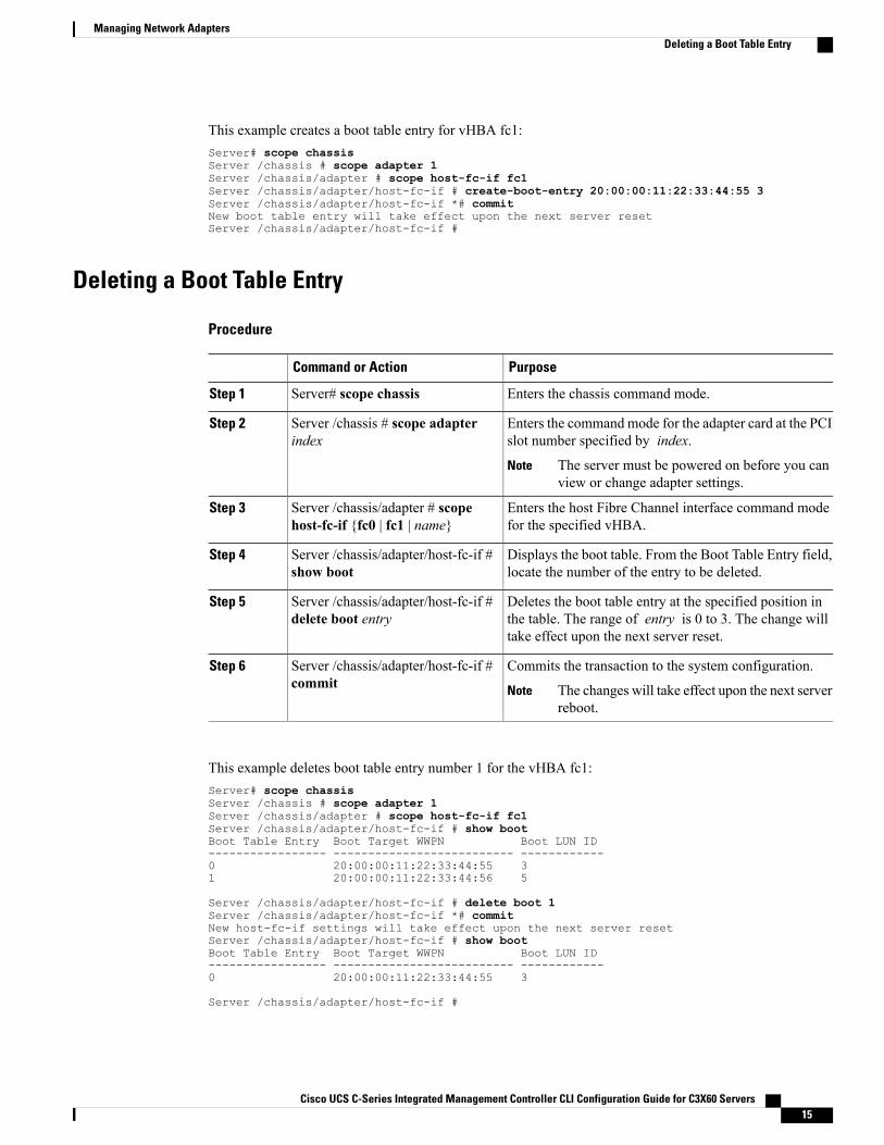
This example creates a boot table entry for vHBA fc1:Server# scope chassisServer /chassis # scope adapter 1Server /chassis/adapter # scope host-fc-if fc1Server /chassis/adapter/host-fc-if # create-boot-entry 20:00:00:11:22:33:44:55 3Server /chassis/adapter/host-fc-if *# commitNew boot table entry will take effect upon the next server resetServer /chassis/adapter/host-fc-if #
Deleting a Boot Table Entry
Procedure
PurposeCommand or Action
Enters the chassis command mode.Server# scope chassisStep 1
Enters the command mode for the adapter card at the PCIslot number specified by index.
Server /chassis # scope adapterindex
Step 2
The server must be powered on before you canview or change adapter settings.
Note
Enters the host Fibre Channel interface command modefor the specified vHBA.
Server /chassis/adapter # scopehost-fc-if {fc0 | fc1 | name}
Step 3
Displays the boot table. From the Boot Table Entry field,locate the number of the entry to be deleted.
Server /chassis/adapter/host-fc-if #show boot
Step 4
Deletes the boot table entry at the specified position inthe table. The range of entry is 0 to 3. The change willtake effect upon the next server reset.
Server /chassis/adapter/host-fc-if #delete boot entry
Step 5
Commits the transaction to the system configuration.Server /chassis/adapter/host-fc-if #commit
Step 6
The changes will take effect upon the next serverreboot.
Note
This example deletes boot table entry number 1 for the vHBA fc1:Server# scope chassisServer /chassis # scope adapter 1Server /chassis/adapter # scope host-fc-if fc1Server /chassis/adapter/host-fc-if # show bootBoot Table Entry Boot Target WWPN Boot LUN ID----------------- -------------------------- ------------0 20:00:00:11:22:33:44:55 31 20:00:00:11:22:33:44:56 5
Server /chassis/adapter/host-fc-if # delete boot 1Server /chassis/adapter/host-fc-if *# commitNew host-fc-if settings will take effect upon the next server resetServer /chassis/adapter/host-fc-if # show bootBoot Table Entry Boot Target WWPN Boot LUN ID----------------- -------------------------- ------------0 20:00:00:11:22:33:44:55 3
Server /chassis/adapter/host-fc-if #
Cisco UCS C-Series Integrated Management Controller CLI Configuration Guide for C3X60 Servers 15
Managing Network AdaptersDeleting a Boot Table Entry
What to Do Next
Reboot the server to apply the changes.
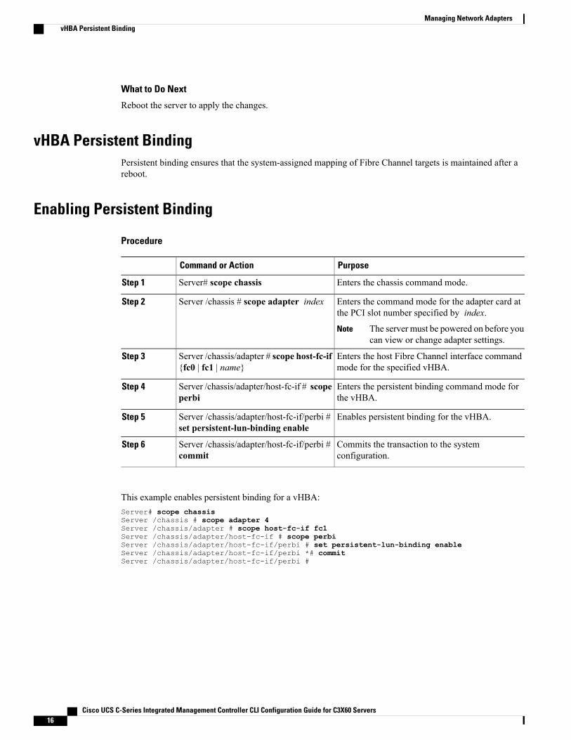
vHBA Persistent BindingPersistent binding ensures that the system-assigned mapping of Fibre Channel targets is maintained after areboot.
Enabling Persistent Binding
Procedure
PurposeCommand or Action
Enters the chassis command mode.Server# scope chassisStep 1
Enters the command mode for the adapter card atthe PCI slot number specified by index.
Server /chassis # scope adapter indexStep 2
The server must be powered on before youcan view or change adapter settings.
Note
Enters the host Fibre Channel interface commandmode for the specified vHBA.
Server /chassis/adapter # scope host-fc-if{fc0 | fc1 | name}
Step 3
Enters the persistent binding command mode forthe vHBA.
Server /chassis/adapter/host-fc-if # scopeperbi
Step 4
Enables persistent binding for the vHBA.Server /chassis/adapter/host-fc-if/perbi #set persistent-lun-binding enable
Step 5
Commits the transaction to the systemconfiguration.
Server /chassis/adapter/host-fc-if/perbi #commit
Step 6
This example enables persistent binding for a vHBA:Server# scope chassisServer /chassis # scope adapter 4Server /chassis/adapter # scope host-fc-if fc1Server /chassis/adapter/host-fc-if # scope perbiServer /chassis/adapter/host-fc-if/perbi # set persistent-lun-binding enableServer /chassis/adapter/host-fc-if/perbi *# commitServer /chassis/adapter/host-fc-if/perbi #
Cisco UCS C-Series Integrated Management Controller CLI Configuration Guide for C3X60 Servers16
Managing Network AdaptersvHBA Persistent Binding
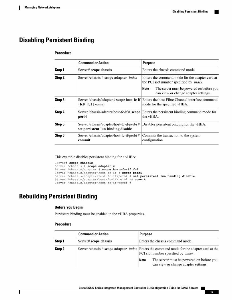
Disabling Persistent Binding
Procedure
PurposeCommand or Action
Enters the chassis command mode.Server# scope chassisStep 1
Enters the command mode for the adapter card atthe PCI slot number specified by index.
Server /chassis # scope adapter indexStep 2
The server must be powered on before youcan view or change adapter settings.
Note
Enters the host Fibre Channel interface commandmode for the specified vHBA.
Server /chassis/adapter # scope host-fc-if{fc0 | fc1 | name}
Step 3
Enters the persistent binding command mode forthe vHBA.
Server /chassis/adapter/host-fc-if # scopeperbi
Step 4
Disables persistent binding for the vHBA.Server /chassis/adapter/host-fc-if/perbi #set persistent-lun-binding disable
Step 5
Commits the transaction to the systemconfiguration.
Server /chassis/adapter/host-fc-if/perbi #commit
Step 6
This example disables persistent binding for a vHBA:Server# scope chassisServer /chassis # scope adapter 4Server /chassis/adapter # scope host-fc-if fc1Server /chassis/adapter/host-fc-if # scope perbiServer /chassis/adapter/host-fc-if/perbi # set persistent-lun-binding disableServer /chassis/adapter/host-fc-if/perbi *# commitServer /chassis/adapter/host-fc-if/perbi #
Rebuilding Persistent Binding
Before You Begin
Persistent binding must be enabled in the vHBA properties.
Procedure
PurposeCommand or Action
Enters the chassis command mode.Server# scope chassisStep 1
Enters the command mode for the adapter card at thePCI slot number specified by index.
Server /chassis # scope adapter indexStep 2
The server must be powered on before youcan view or change adapter settings.
Note
Cisco UCS C-Series Integrated Management Controller CLI Configuration Guide for C3X60 Servers 17
Managing Network AdaptersDisabling Persistent Binding
PurposeCommand or Action
Enters the host Fibre Channel interface commandmode for the specified vHBA.
Server /chassis/adapter # scopehost-fc-if {fc0 | fc1 | name}
Step 3
Enters the persistent binding command mode for thevHBA.
Server /chassis/adapter/host-fc-if #scope perbi
Step 4
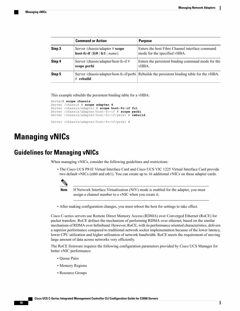
Rebuilds the persistent binding table for the vHBA.Server /chassis/adapter/host-fc-if/perbi# rebuild
Step 5
This example rebuilds the persistent binding table for a vHBA:Server# scope chassisServer /chassis # scope adapter 4Server /chassis/adapter # scope host-fc-if fc1Server /chassis/adapter/host-fc-if # scope perbiServer /chassis/adapter/host-fc-if/perbi # rebuild
Server /chassis/adapter/host-fc-if/perbi #
Managing vNICs
Guidelines for Managing vNICsWhen managing vNICs, consider the following guidelines and restrictions:
• The Cisco UCS P81E Virtual Interface Card and Cisco UCS VIC 1225 Virtual Interface Card providetwo default vNICs (eth0 and eth1). You can create up to 16 additional vNICs on these adapter cards.
If Network Interface Virtualization (NIV) mode is enabled for the adapter, you mustassign a channel number to a vNIC when you create it.
Note
• After making configuration changes, you must reboot the host for settings to take effect.
Cisco C-series servers use Remote Direct Memory Access (RDMA) over Converged Ethernet (RoCE) forpacket transfers. RoCE defines the mechanism of performing RDMA over ethernet, based on the similarmechanism of RDMA over Infiniband. However, RoCE, with its performance oriented characteristics, deliversa superior performance compared to traditional network socket implementation because of the lower latency,lower CPU utilization and higher utilization of network bandwidth. RoCE meets the requirement of movinglarge amount of data across networks very efficiently.
The RoCE firmware requires the following configuration parameters provided by Cisco UCS Manager forbetter vNIC performance:
• Queue Pairs
• Memory Regions
• Resource Groups
Cisco UCS C-Series Integrated Management Controller CLI Configuration Guide for C3X60 Servers18
Managing Network AdaptersManaging vNICs
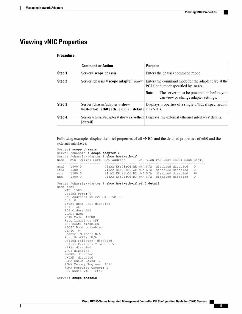
Viewing vNIC Properties
Procedure
PurposeCommand or Action
Enters the chassis command mode.Server# scope chassisStep 1
Enters the command mode for the adapter card at thePCI slot number specified by index.
Server /chassis # scope adapter indexStep 2
The server must be powered on before youcan view or change adapter settings.
Note
Displays properties of a single vNIC, if specified, orall vNICs.
Server /chassis/adapter # showhost-eth-if [eth0 | eth1 | name] [detail]
Step 3
Displays the external ethernet interfaces' details.Server /chassis/adapter # show ext-eth-if[detail]
Step 4
Following examples display the brief properties of all vNICs and the detailed properties of eth0 and theexternal interfaces:Server# scope chassisServer /chassis # scope adapter 1Server /chassis/adapter # show host-eth-ifName MTU Uplink Port MAC Address CoS VLAN PXE Boot iSCSI Boot usNIC----- ----- ----------- ------------ --- ------------ --------------- ------eth0 1500 0 74:A2:E6:28:C6:AE N/A N/A disabled disabled 0eth1 1500 1 74:A2:E6:28:C6:AF N/A N/A disabled disabled 0srg 1500 0 74:A2:E6:28:C6:B2 N/A N/A disabled disabled 64hhh 1500 0 74:A2:E6:28:C6:B3 N/A N/A disabled disabled 0
Server /chassis/adapter # show host-eth-if eth0 detailName eth0:
MTU: 1500Uplink Port: 0MAC Address: 00:22:BD:D6:5C:33CoS: 0Trust Host CoS: disabledPCI Link: 0PCI Order: ANYVLAN: NONEVLAN Mode: TRUNKRate Limiting: OFFPXE Boot: disablediSCSI Boot: disabledusNIC: 0Channel Number: N/APort Profile: N/AUplink Failover: disabledUplink Failback Timeout: 5aRFS: disabledVMQ: disabledNVGRE: disabledVXLAN: disabledRDMA Queue Pairs: 1RDMA Memory Regions: 4096RDMA Resource Groups: 1CDN Name: VIC-1-eth0
Server# scope chassis
Cisco UCS C-Series Integrated Management Controller CLI Configuration Guide for C3X60 Servers 19
Managing Network AdaptersViewing vNIC Properties
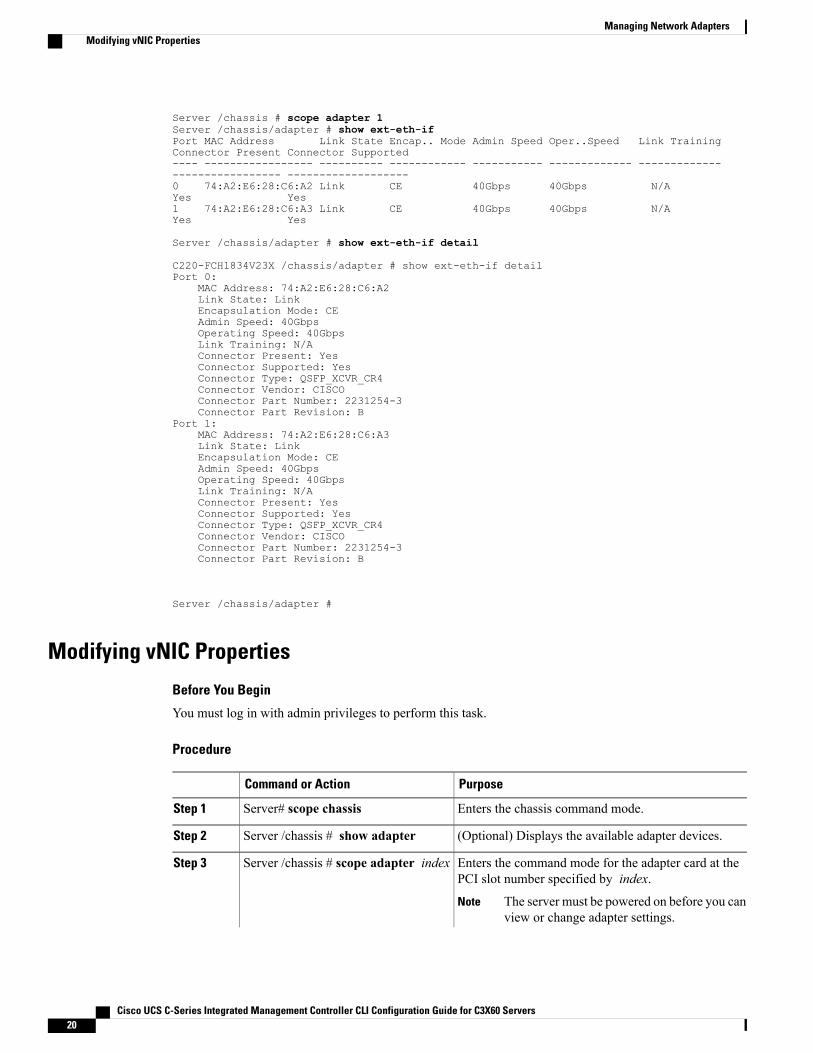
Server /chassis # scope adapter 1Server /chassis/adapter # show ext-eth-ifPort MAC Address Link State Encap.. Mode Admin Speed Oper..Speed Link TrainingConnector Present Connector Supported---- ----------------- ---------- ------------ ----------- ------------- ------------------------------ -------------------0 74:A2:E6:28:C6:A2 Link CE 40Gbps 40Gbps N/AYes Yes1 74:A2:E6:28:C6:A3 Link CE 40Gbps 40Gbps N/AYes Yes
Server /chassis/adapter # show ext-eth-if detail
C220-FCH1834V23X /chassis/adapter # show ext-eth-if detailPort 0:
MAC Address: 74:A2:E6:28:C6:A2Link State: LinkEncapsulation Mode: CEAdmin Speed: 40GbpsOperating Speed: 40GbpsLink Training: N/AConnector Present: YesConnector Supported: YesConnector Type: QSFP_XCVR_CR4Connector Vendor: CISCOConnector Part Number: 2231254-3Connector Part Revision: B
Port 1:MAC Address: 74:A2:E6:28:C6:A3Link State: LinkEncapsulation Mode: CEAdmin Speed: 40GbpsOperating Speed: 40GbpsLink Training: N/AConnector Present: YesConnector Supported: YesConnector Type: QSFP_XCVR_CR4Connector Vendor: CISCOConnector Part Number: 2231254-3Connector Part Revision: B
Server /chassis/adapter #
Modifying vNIC Properties
Before You Begin
You must log in with admin privileges to perform this task.
Procedure
PurposeCommand or Action
Enters the chassis command mode.Server# scope chassisStep 1
(Optional) Displays the available adapter devices.Server /chassis # show adapterStep 2
Enters the command mode for the adapter card at thePCI slot number specified by index.
Server /chassis # scope adapter indexStep 3
The server must be powered on before you canview or change adapter settings.
Note
Cisco UCS C-Series Integrated Management Controller CLI Configuration Guide for C3X60 Servers20
Managing Network AdaptersModifying vNIC Properties
PurposeCommand or Action
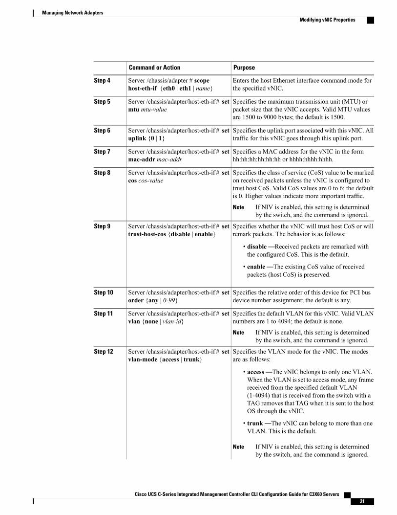
Enters the host Ethernet interface command mode forthe specified vNIC.
Server /chassis/adapter # scopehost-eth-if {eth0 | eth1 | name}
Step 4
Specifies the maximum transmission unit (MTU) orpacket size that the vNIC accepts. Valid MTU valuesare 1500 to 9000 bytes; the default is 1500.
Server /chassis/adapter/host-eth-if # setmtu mtu-value
Step 5
Specifies the uplink port associated with this vNIC. Alltraffic for this vNIC goes through this uplink port.
Server /chassis/adapter/host-eth-if # setuplink {0 | 1}
Step 6
Specifies a MAC address for the vNIC in the formhh:hh:hh:hh:hh:hh or hhhh:hhhh:hhhh.
Server /chassis/adapter/host-eth-if # setmac-addr mac-addr
Step 7
Specifies the class of service (CoS) value to be markedon received packets unless the vNIC is configured to
Server /chassis/adapter/host-eth-if # setcos cos-value
Step 8
trust host CoS. Valid CoS values are 0 to 6; the defaultis 0. Higher values indicate more important traffic.
If NIV is enabled, this setting is determinedby the switch, and the command is ignored.
Note
Specifies whether the vNIC will trust host CoS or willremark packets. The behavior is as follows:
Server /chassis/adapter/host-eth-if # settrust-host-cos {disable | enable}
Step 9
• disable—Received packets are remarked withthe configured CoS. This is the default.
• enable—The existing CoS value of receivedpackets (host CoS) is preserved.
Specifies the relative order of this device for PCI busdevice number assignment; the default is any.
Server /chassis/adapter/host-eth-if # setorder {any | 0-99}
Step 10
Specifies the default VLAN for this vNIC. Valid VLANnumbers are 1 to 4094; the default is none.
Server /chassis/adapter/host-eth-if # setvlan {none | vlan-id}
Step 11
If NIV is enabled, this setting is determinedby the switch, and the command is ignored.
Note
Specifies the VLAN mode for the vNIC. The modesare as follows:
Server /chassis/adapter/host-eth-if # setvlan-mode {access | trunk}
Step 12
• access—The vNIC belongs to only one VLAN.When the VLAN is set to access mode, any framereceived from the specified default VLAN(1-4094) that is received from the switch with aTAG removes that TAGwhen it is sent to the hostOS through the vNIC.
• trunk—The vNIC can belong to more than oneVLAN. This is the default.
If NIV is enabled, this setting is determinedby the switch, and the command is ignored.
Note
Cisco UCS C-Series Integrated Management Controller CLI Configuration Guide for C3X60 Servers 21
Managing Network AdaptersModifying vNIC Properties
PurposeCommand or Action
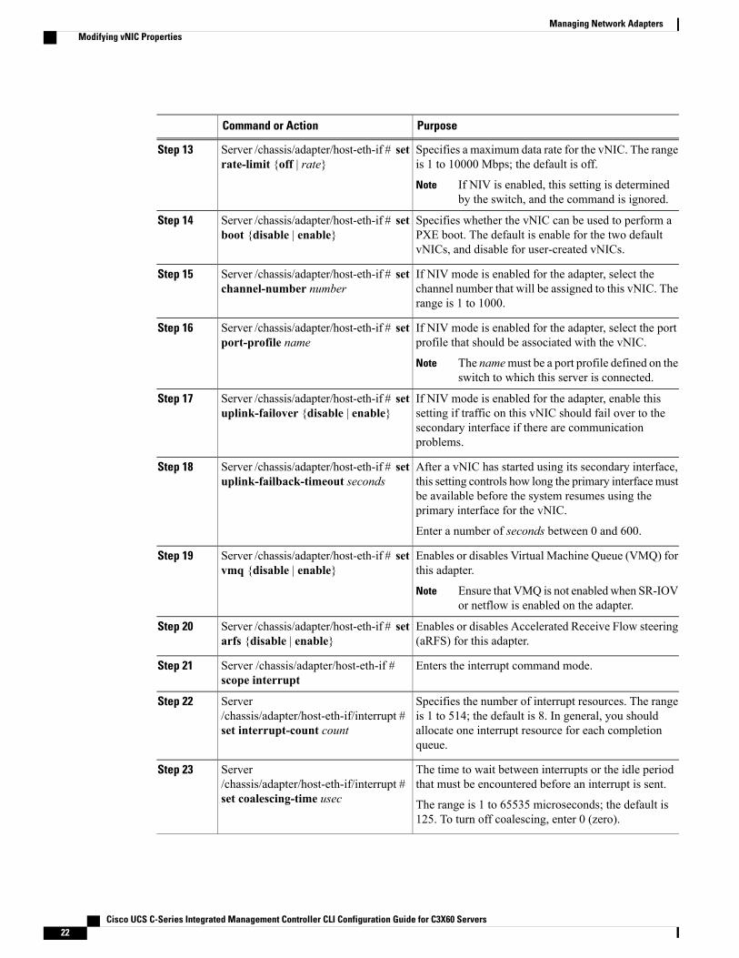
Specifies a maximum data rate for the vNIC. The rangeis 1 to 10000 Mbps; the default is off.
Server /chassis/adapter/host-eth-if # setrate-limit {off | rate}
Step 13
If NIV is enabled, this setting is determinedby the switch, and the command is ignored.
Note
Specifies whether the vNIC can be used to perform aPXE boot. The default is enable for the two defaultvNICs, and disable for user-created vNICs.
Server /chassis/adapter/host-eth-if # setboot {disable | enable}
Step 14
If NIV mode is enabled for the adapter, select thechannel number that will be assigned to this vNIC. Therange is 1 to 1000.
Server /chassis/adapter/host-eth-if # setchannel-number number
Step 15
If NIV mode is enabled for the adapter, select the portprofile that should be associated with the vNIC.
Server /chassis/adapter/host-eth-if # setport-profile name
Step 16
The namemust be a port profile defined on theswitch to which this server is connected.
Note
If NIV mode is enabled for the adapter, enable thissetting if traffic on this vNIC should fail over to the
Server /chassis/adapter/host-eth-if # setuplink-failover {disable | enable}
Step 17
secondary interface if there are communicationproblems.
After a vNIC has started using its secondary interface,this setting controls how long the primary interfacemust
Server /chassis/adapter/host-eth-if # setuplink-failback-timeout seconds
Step 18
be available before the system resumes using theprimary interface for the vNIC.
Enter a number of seconds between 0 and 600.
Enables or disables Virtual Machine Queue (VMQ) forthis adapter.
Server /chassis/adapter/host-eth-if # setvmq {disable | enable}
Step 19
Ensure that VMQ is not enabled when SR-IOVor netflow is enabled on the adapter.
Note
Enables or disables Accelerated Receive Flow steering(aRFS) for this adapter.
Server /chassis/adapter/host-eth-if # setarfs {disable | enable}
Step 20
Enters the interrupt command mode.Server /chassis/adapter/host-eth-if #scope interrupt
Step 21
Specifies the number of interrupt resources. The rangeis 1 to 514; the default is 8. In general, you should
Server/chassis/adapter/host-eth-if/interrupt #set interrupt-count count
Step 22
allocate one interrupt resource for each completionqueue.
The time to wait between interrupts or the idle periodthat must be encountered before an interrupt is sent.
Server/chassis/adapter/host-eth-if/interrupt #set coalescing-time usec
Step 23
The range is 1 to 65535 microseconds; the default is125. To turn off coalescing, enter 0 (zero).
Cisco UCS C-Series Integrated Management Controller CLI Configuration Guide for C3X60 Servers22
Managing Network AdaptersModifying vNIC Properties
PurposeCommand or Action
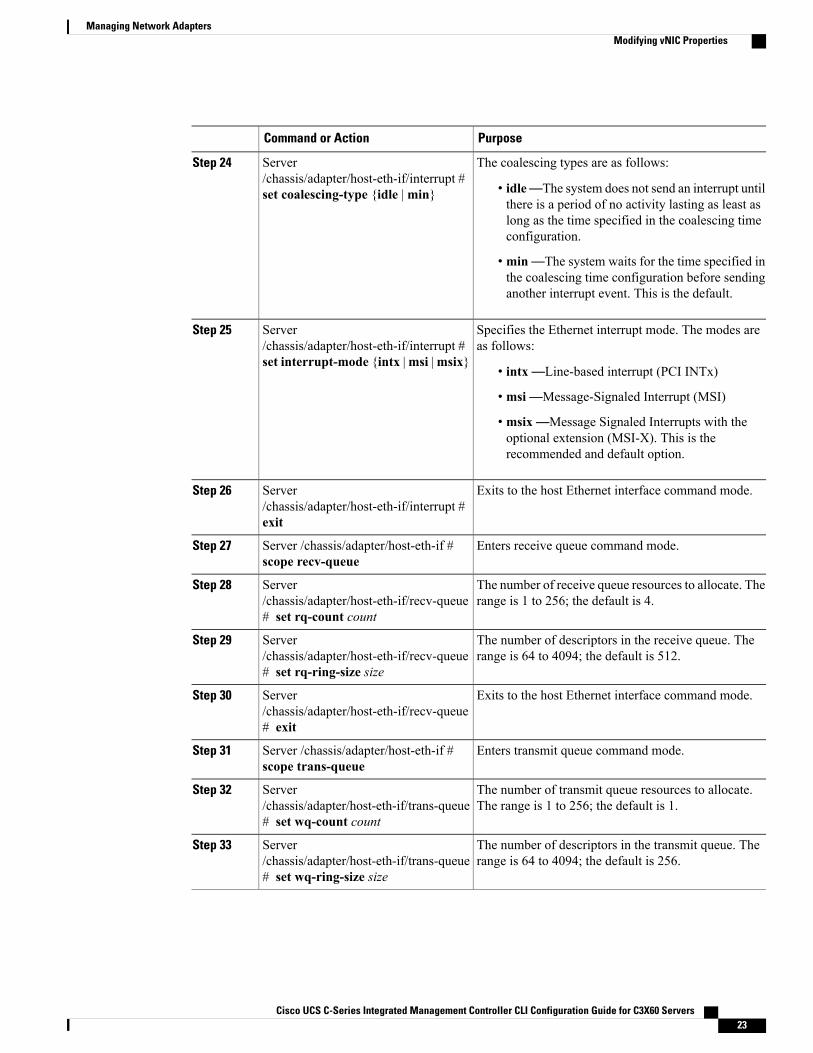
The coalescing types are as follows:Server/chassis/adapter/host-eth-if/interrupt #set coalescing-type {idle |min}
Step 24
• idle—The system does not send an interrupt untilthere is a period of no activity lasting as least aslong as the time specified in the coalescing timeconfiguration.
• min—The system waits for the time specified inthe coalescing time configuration before sendinganother interrupt event. This is the default.
Specifies the Ethernet interrupt mode. The modes areas follows:
Server/chassis/adapter/host-eth-if/interrupt #set interrupt-mode {intx |msi |msix}
Step 25
• intx—Line-based interrupt (PCI INTx)
• msi—Message-Signaled Interrupt (MSI)
• msix—Message Signaled Interrupts with theoptional extension (MSI-X). This is therecommended and default option.
Exits to the host Ethernet interface command mode.Server/chassis/adapter/host-eth-if/interrupt #exit
Step 26
Enters receive queue command mode.Server /chassis/adapter/host-eth-if #scope recv-queue
Step 27
The number of receive queue resources to allocate. Therange is 1 to 256; the default is 4.
Server/chassis/adapter/host-eth-if/recv-queue# set rq-count count
Step 28
The number of descriptors in the receive queue. Therange is 64 to 4094; the default is 512.
Server/chassis/adapter/host-eth-if/recv-queue# set rq-ring-size size
Step 29
Exits to the host Ethernet interface command mode.Server/chassis/adapter/host-eth-if/recv-queue# exit
Step 30
Enters transmit queue command mode.Server /chassis/adapter/host-eth-if #scope trans-queue
Step 31
The number of transmit queue resources to allocate.The range is 1 to 256; the default is 1.
Server/chassis/adapter/host-eth-if/trans-queue# set wq-count count
Step 32
The number of descriptors in the transmit queue. Therange is 64 to 4094; the default is 256.
Server/chassis/adapter/host-eth-if/trans-queue# set wq-ring-size size
Step 33
Cisco UCS C-Series Integrated Management Controller CLI Configuration Guide for C3X60 Servers 23
Managing Network AdaptersModifying vNIC Properties
PurposeCommand or Action
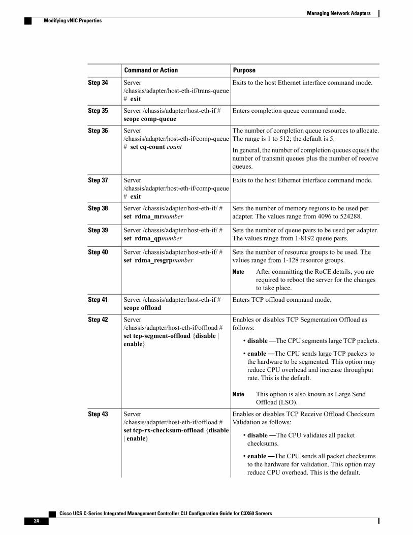
Exits to the host Ethernet interface command mode.Server/chassis/adapter/host-eth-if/trans-queue# exit
Step 34
Enters completion queue command mode.Server /chassis/adapter/host-eth-if #scope comp-queue
Step 35
The number of completion queue resources to allocate.The range is 1 to 512; the default is 5.
Server/chassis/adapter/host-eth-if/comp-queue# set cq-count count
Step 36
In general, the number of completion queues equals thenumber of transmit queues plus the number of receivequeues.
Exits to the host Ethernet interface command mode.Server/chassis/adapter/host-eth-if/comp-queue# exit
Step 37
Sets the number of memory regions to be used peradapter. The values range from 4096 to 524288.
Server /chassis/adapter/host-eth-if/ #set rdma_mrnumber
Step 38
Sets the number of queue pairs to be used per adapter.The values range from 1-8192 queue pairs.
Server /chassis/adapter/host-eth-if/ #set rdma_qpnumber
Step 39
Sets the number of resource groups to be used. Thevalues range from 1-128 resource groups.
Server /chassis/adapter/host-eth-if/ #set rdma_resgrpnumber
Step 40
After committing the RoCE details, you arerequired to reboot the server for the changesto take place.
Note
Enters TCP offload command mode.Server /chassis/adapter/host-eth-if #scope offload
Step 41
Enables or disables TCP Segmentation Offload asfollows:
Server/chassis/adapter/host-eth-if/offload #set tcp-segment-offload {disable |enable}
Step 42
• disable—The CPU segments large TCP packets.
• enable—The CPU sends large TCP packets tothe hardware to be segmented. This option mayreduce CPU overhead and increase throughputrate. This is the default.
This option is also known as Large SendOffload (LSO).
Note
Enables or disables TCP Receive Offload ChecksumValidation as follows:
Server/chassis/adapter/host-eth-if/offload #set tcp-rx-checksum-offload {disable| enable}
Step 43
• disable—The CPU validates all packetchecksums.
• enable—The CPU sends all packet checksumsto the hardware for validation. This option mayreduce CPU overhead. This is the default.
Cisco UCS C-Series Integrated Management Controller CLI Configuration Guide for C3X60 Servers24
Managing Network AdaptersModifying vNIC Properties
PurposeCommand or Action
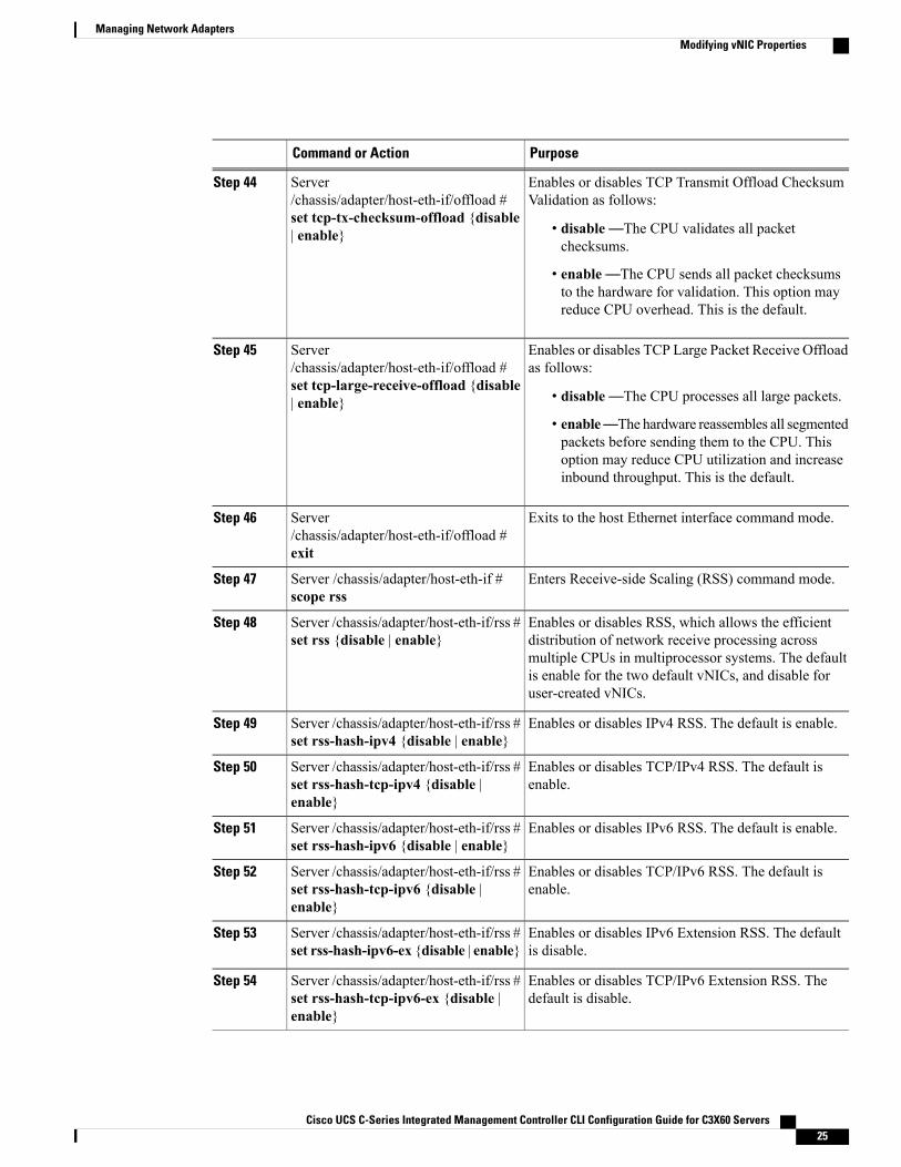
Enables or disables TCP Transmit Offload ChecksumValidation as follows:
Server/chassis/adapter/host-eth-if/offload #set tcp-tx-checksum-offload {disable| enable}
Step 44
• disable—The CPU validates all packetchecksums.
• enable—The CPU sends all packet checksumsto the hardware for validation. This option mayreduce CPU overhead. This is the default.
Enables or disables TCP Large Packet Receive Offloadas follows:
Server/chassis/adapter/host-eth-if/offload #set tcp-large-receive-offload {disable| enable}
Step 45
• disable—The CPU processes all large packets.
• enable—The hardware reassembles all segmentedpackets before sending them to the CPU. Thisoption may reduce CPU utilization and increaseinbound throughput. This is the default.
Exits to the host Ethernet interface command mode.Server/chassis/adapter/host-eth-if/offload #exit
Step 46
Enters Receive-side Scaling (RSS) command mode.Server /chassis/adapter/host-eth-if #scope rss
Step 47
Enables or disables RSS, which allows the efficientdistribution of network receive processing across
Server /chassis/adapter/host-eth-if/rss #set rss {disable | enable}
Step 48
multiple CPUs in multiprocessor systems. The defaultis enable for the two default vNICs, and disable foruser-created vNICs.
Enables or disables IPv4 RSS. The default is enable.Server /chassis/adapter/host-eth-if/rss #set rss-hash-ipv4 {disable | enable}
Step 49
Enables or disables TCP/IPv4 RSS. The default isenable.
Server /chassis/adapter/host-eth-if/rss #set rss-hash-tcp-ipv4 {disable |enable}
Step 50
Enables or disables IPv6 RSS. The default is enable.Server /chassis/adapter/host-eth-if/rss #set rss-hash-ipv6 {disable | enable}
Step 51
Enables or disables TCP/IPv6 RSS. The default isenable.
Server /chassis/adapter/host-eth-if/rss #set rss-hash-tcp-ipv6 {disable |enable}
Step 52
Enables or disables IPv6 Extension RSS. The defaultis disable.
Server /chassis/adapter/host-eth-if/rss #set rss-hash-ipv6-ex {disable | enable}
Step 53
Enables or disables TCP/IPv6 Extension RSS. Thedefault is disable.
Server /chassis/adapter/host-eth-if/rss #set rss-hash-tcp-ipv6-ex {disable |enable}
Step 54
Cisco UCS C-Series Integrated Management Controller CLI Configuration Guide for C3X60 Servers 25
Managing Network AdaptersModifying vNIC Properties
PurposeCommand or Action
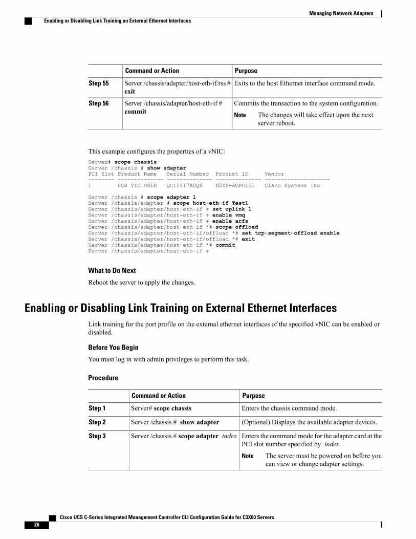
Exits to the host Ethernet interface command mode.Server /chassis/adapter/host-eth-if/rss #exit
Step 55
Commits the transaction to the system configuration.Server /chassis/adapter/host-eth-if #commit
Step 56
The changes will take effect upon the nextserver reboot.
Note
This example configures the properties of a vNIC:Server# scope chassisServer /chassis # show adapterPCI Slot Product Name Serial Number Product ID Vendor-------- -------------- -------------- -------------- --------------------1 UCS VIC P81E QCI1417A0QK N2XX-ACPCI01 Cisco Systems Inc
Server /chassis # scope adapter 1Server /chassis/adapter # scope host-eth-if Test1Server /chassis/adapter/host-eth-if # set uplink 1Server /chassis/adapter/host-eth-if # enable vmqServer /chassis/adapter/host-eth-if # enable arfsServer /chassis/adapter/host-eth-if *# scope offloadServer /chassis/adapter/host-eth-if/offload *# set tcp-segment-offload enableServer /chassis/adapter/host-eth-if/offload *# exitServer /chassis/adapter/host-eth-if *# commitServer /chassis/adapter/host-eth-if #
What to Do Next
Reboot the server to apply the changes.
Enabling or Disabling Link Training on External Ethernet InterfacesLink training for the port profile on the external ethernet interfaces of the specified vNIC can be enabled ordisabled.
Before You Begin
You must log in with admin privileges to perform this task.
Procedure
PurposeCommand or Action
Enters the chassis command mode.Server# scope chassisStep 1
(Optional) Displays the available adapter devices.Server /chassis # show adapterStep 2
Enters the commandmode for the adapter card at thePCI slot number specified by index.
Server /chassis # scope adapter indexStep 3
The server must be powered on before youcan view or change adapter settings.
Note
Cisco UCS C-Series Integrated Management Controller CLI Configuration Guide for C3X60 Servers26
Managing Network AdaptersEnabling or Disabling Link Training on External Ethernet Interfaces
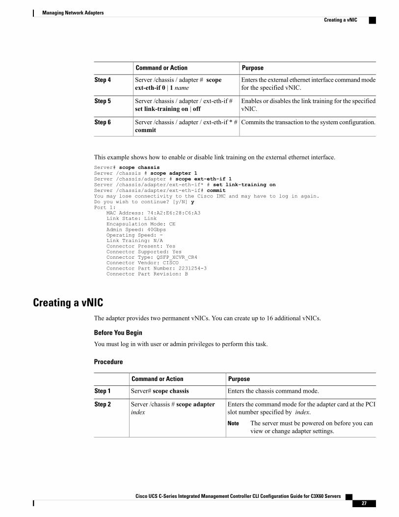
PurposeCommand or Action
Enters the external ethernet interface commandmodefor the specified vNIC.
Server /chassis / adapter # scopeext-eth-if 0 | 1 name
Step 4
Enables or disables the link training for the specifiedvNIC.
Server /chassis / adapter / ext-eth-if #set link-training on | off
Step 5
Commits the transaction to the system configuration.Server /chassis / adapter / ext-eth-if * #commit
Step 6
This example shows how to enable or disable link training on the external ethernet interface.Server# scope chassisServer /chassis # scope adapter 1Server /chassis/adapter # scope ext-eth-if 1Server /chassis/adapter/ext-eth-if* # set link-training onServer /chassis/adapter/ext-eth-if# commitYou may lose connectivity to the Cisco IMC and may have to log in again.Do you wish to continue? [y/N] yPort 1:
MAC Address: 74:A2:E6:28:C6:A3Link State: LinkEncapsulation Mode: CEAdmin Speed: 40GbpsOperating Speed: -Link Training: N/AConnector Present: YesConnector Supported: YesConnector Type: QSFP_XCVR_CR4Connector Vendor: CISCOConnector Part Number: 2231254-3Connector Part Revision: B
Creating a vNICThe adapter provides two permanent vNICs. You can create up to 16 additional vNICs.
Before You Begin
You must log in with user or admin privileges to perform this task.
Procedure
PurposeCommand or Action
Enters the chassis command mode.Server# scope chassisStep 1
Enters the command mode for the adapter card at the PCIslot number specified by index.
Server /chassis # scope adapterindex
Step 2
The server must be powered on before you canview or change adapter settings.
Note
Cisco UCS C-Series Integrated Management Controller CLI Configuration Guide for C3X60 Servers 27
Managing Network AdaptersCreating a vNIC
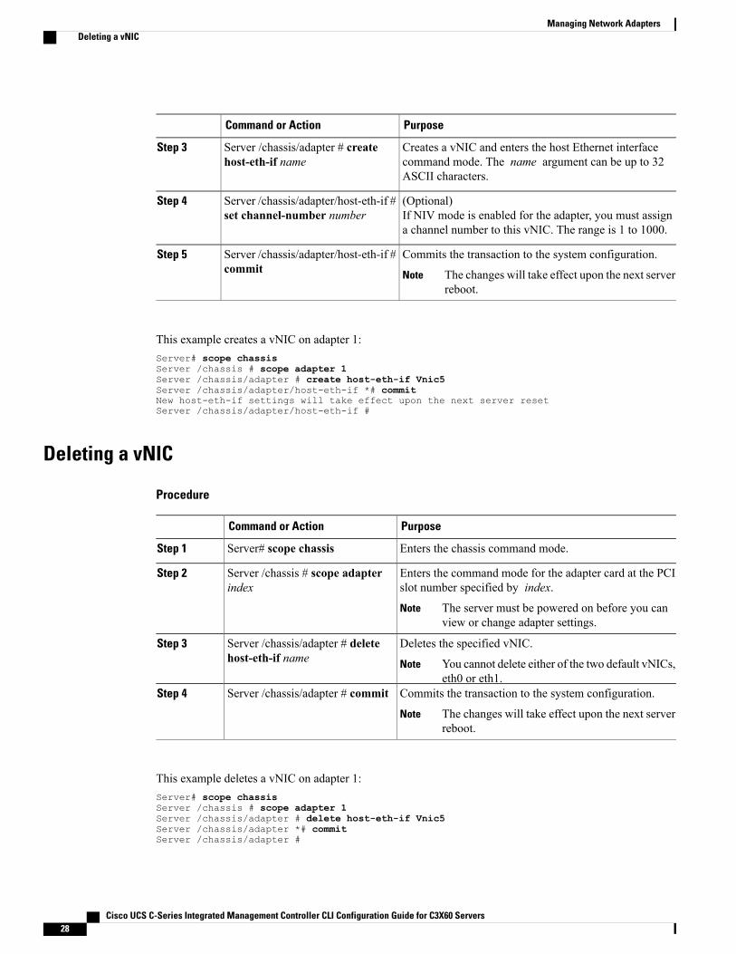
PurposeCommand or Action
Creates a vNIC and enters the host Ethernet interfacecommand mode. The name argument can be up to 32ASCII characters.
Server /chassis/adapter # createhost-eth-if name
Step 3
(Optional)If NIV mode is enabled for the adapter, you must assigna channel number to this vNIC. The range is 1 to 1000.
Server /chassis/adapter/host-eth-if #set channel-number number
Step 4
Commits the transaction to the system configuration.Server /chassis/adapter/host-eth-if #commit
Step 5
The changes will take effect upon the next serverreboot.
Note
This example creates a vNIC on adapter 1:Server# scope chassisServer /chassis # scope adapter 1Server /chassis/adapter # create host-eth-if Vnic5Server /chassis/adapter/host-eth-if *# commitNew host-eth-if settings will take effect upon the next server resetServer /chassis/adapter/host-eth-if #
Deleting a vNIC
Procedure
PurposeCommand or Action
Enters the chassis command mode.Server# scope chassisStep 1
Enters the command mode for the adapter card at the PCIslot number specified by index.
Server /chassis # scope adapterindex
Step 2
The server must be powered on before you canview or change adapter settings.
Note
Deletes the specified vNIC.Server /chassis/adapter # deletehost-eth-if name
Step 3
You cannot delete either of the two default vNICs,eth0 or eth1.
Note
Commits the transaction to the system configuration.Server /chassis/adapter # commitStep 4
The changes will take effect upon the next serverreboot.
Note
This example deletes a vNIC on adapter 1:Server# scope chassisServer /chassis # scope adapter 1Server /chassis/adapter # delete host-eth-if Vnic5Server /chassis/adapter *# commitServer /chassis/adapter #
Cisco UCS C-Series Integrated Management Controller CLI Configuration Guide for C3X60 Servers28
Managing Network AdaptersDeleting a vNIC
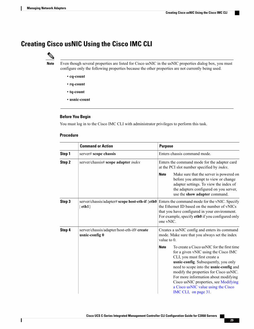
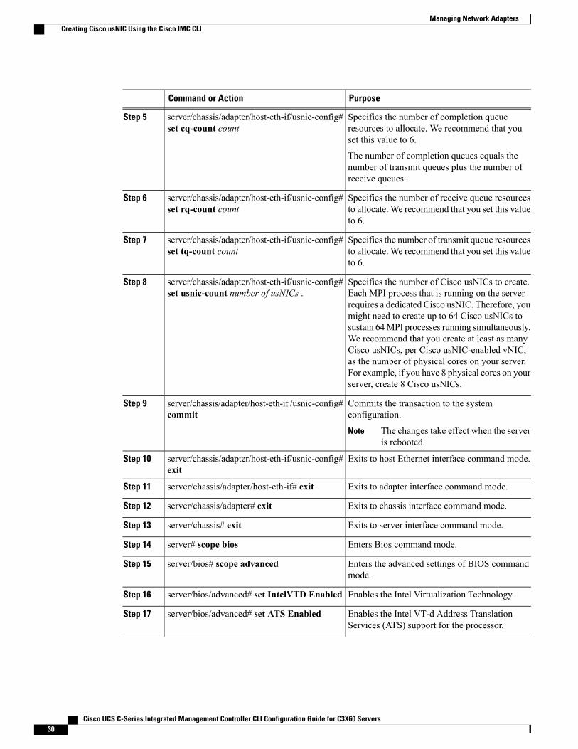
Creating Cisco usNIC Using the Cisco IMC CLI
Even though several properties are listed for Cisco usNIC in the usNIC properties dialog box, you mustconfigure only the following properties because the other properties are not currently being used.
Note
• cq-count
• rq-count
• tq-count
• usnic-count
Before You Begin
You must log in to the Cisco IMC CLI with administrator privileges to perform this task.
Procedure
PurposeCommand or Action
Enters chassis command mode.server# scope chassisStep 1
Enters the command mode for the adapter cardat the PCI slot number specified by index.
server/chassis# scope adapter indexStep 2
Make sure that the server is powered onbefore you attempt to view or changeadapter settings. To view the index ofthe adapters configured on you server,use the show adapter command.
Note
Enters the command mode for the vNIC. Specifythe Ethernet ID based on the number of vNICs
server/chassis/adapter# scope host-eth-if {eth0| eth1}
Step 3
that you have configured in your environment.For example, specify eth0 if you configured onlyone vNIC.
Creates a usNIC config and enters its commandmode. Make sure that you always set the indexvalue to 0.
server/chassis/adapter/host-eth-if# createusnic-config 0
Step 4
To create a Cisco usNIC for the first timefor a given vNIC using the Cisco IMCCLI, you must first create ausnic-config. Subsequently, you onlyneed to scope into the usnic-config andmodify the properties for Cisco usNIC.For more information about modifyingCisco usNIC properties, see Modifyinga Cisco usNIC value using the CiscoIMC CLI, on page 31.
Note
Cisco UCS C-Series Integrated Management Controller CLI Configuration Guide for C3X60 Servers 29
Managing Network AdaptersCreating Cisco usNIC Using the Cisco IMC CLI
PurposeCommand or Action
Specifies the number of completion queueresources to allocate. We recommend that youset this value to 6.
server/chassis/adapter/host-eth-if/usnic-config#set cq-count count
Step 5
The number of completion queues equals thenumber of transmit queues plus the number ofreceive queues.
Specifies the number of receive queue resourcesto allocate.We recommend that you set this valueto 6.
server/chassis/adapter/host-eth-if/usnic-config#set rq-count count
Step 6
Specifies the number of transmit queue resourcesto allocate.We recommend that you set this valueto 6.
server/chassis/adapter/host-eth-if/usnic-config#set tq-count count
Step 7
Specifies the number of Cisco usNICs to create.Each MPI process that is running on the server
server/chassis/adapter/host-eth-if/usnic-config#set usnic-count number of usNICs .
Step 8
requires a dedicated Cisco usNIC. Therefore, youmight need to create up to 64 Cisco usNICs tosustain 64MPI processes running simultaneously.We recommend that you create at least as manyCisco usNICs, per Cisco usNIC-enabled vNIC,as the number of physical cores on your server.For example, if you have 8 physical cores on yourserver, create 8 Cisco usNICs.
Commits the transaction to the systemconfiguration.
server/chassis/adapter/host-eth-if /usnic-config#commit
Step 9
The changes take effect when the serveris rebooted.
Note
Exits to host Ethernet interface command mode.server/chassis/adapter/host-eth-if/usnic-config#exit
Step 10
Exits to adapter interface command mode.server/chassis/adapter/host-eth-if# exitStep 11
Exits to chassis interface command mode.server/chassis/adapter# exitStep 12
Exits to server interface command mode.server/chassis# exitStep 13
Enters Bios command mode.server# scope biosStep 14
Enters the advanced settings of BIOS commandmode.
server/bios# scope advancedStep 15
Enables the Intel Virtualization Technology.server/bios/advanced# set IntelVTD EnabledStep 16
Enables the Intel VT-d Address TranslationServices (ATS) support for the processor.
server/bios/advanced# set ATS EnabledStep 17
Cisco UCS C-Series Integrated Management Controller CLI Configuration Guide for C3X60 Servers30
Managing Network AdaptersCreating Cisco usNIC Using the Cisco IMC CLI
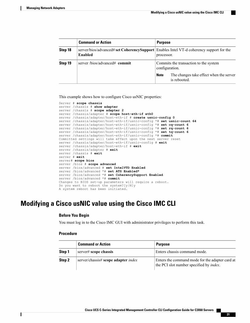
PurposeCommand or Action
Enables Intel VT-d coherency support for theprocessor.
server/bios/advanced# set CoherencySupportEnabled
Step 18
Commits the transaction to the systemconfiguration.
server /bios/advanced# commitStep 19
The changes take effect when the serveris rebooted.
Note
This example shows how to configure Cisco usNIC properties:Server # scope chassisserver /chassis # show adapterserver /chassis # scope adapter 2server /chassis/adapter # scope host-eth-if eth0server /chassis/adapter/host-eth-if # create usnic-config 0server /chassis/adapter/host-eth-if/usnic-config *# set usnic-count 64server /chassis/adapter/host-eth-if/usnic-config *# set cq-count 6server /chassis/adapter/host-eth-if/usnic-config *# set rq-count 6server /chassis/adapter/host-eth-if/usnic-config *# set tq-count 6server /chassis/adapter/host-eth-if/usnic-config *# commitCommitted settings will take effect upon the next server resetserver /chassis/adapter/host-eth-if/usnic-config # exitserver /chassis/adapter/host-eth-if # exitserver /chassis/adapter # exitserver /chassis # exitserver # exitserver# scope biosserver /bios # scope advancedserver /bios/advanced # set IntelVTD Enabledserver /bios/advanced *# set ATS Enabled*server /bios/advanced *# set CoherencySupport Enabledserver /bios/advanced *# commitChanges to BIOS set-up parameters will require a reboot.Do you want to reboot the system?[y|N]yA system reboot has been initiated.
Modifying a Cisco usNIC value using the Cisco IMC CLI
Before You Begin
You must log in to the Cisco IMC GUI with administrator privileges to perform this task.
Procedure
PurposeCommand or Action
Enters chassis command mode.server# scope chassisStep 1
Enters the command mode for the adapter card atthe PCI slot number specified by index.
server/chassis# scope adapter indexStep 2
Cisco UCS C-Series Integrated Management Controller CLI Configuration Guide for C3X60 Servers 31
Managing Network AdaptersModifying a Cisco usNIC value using the Cisco IMC CLI
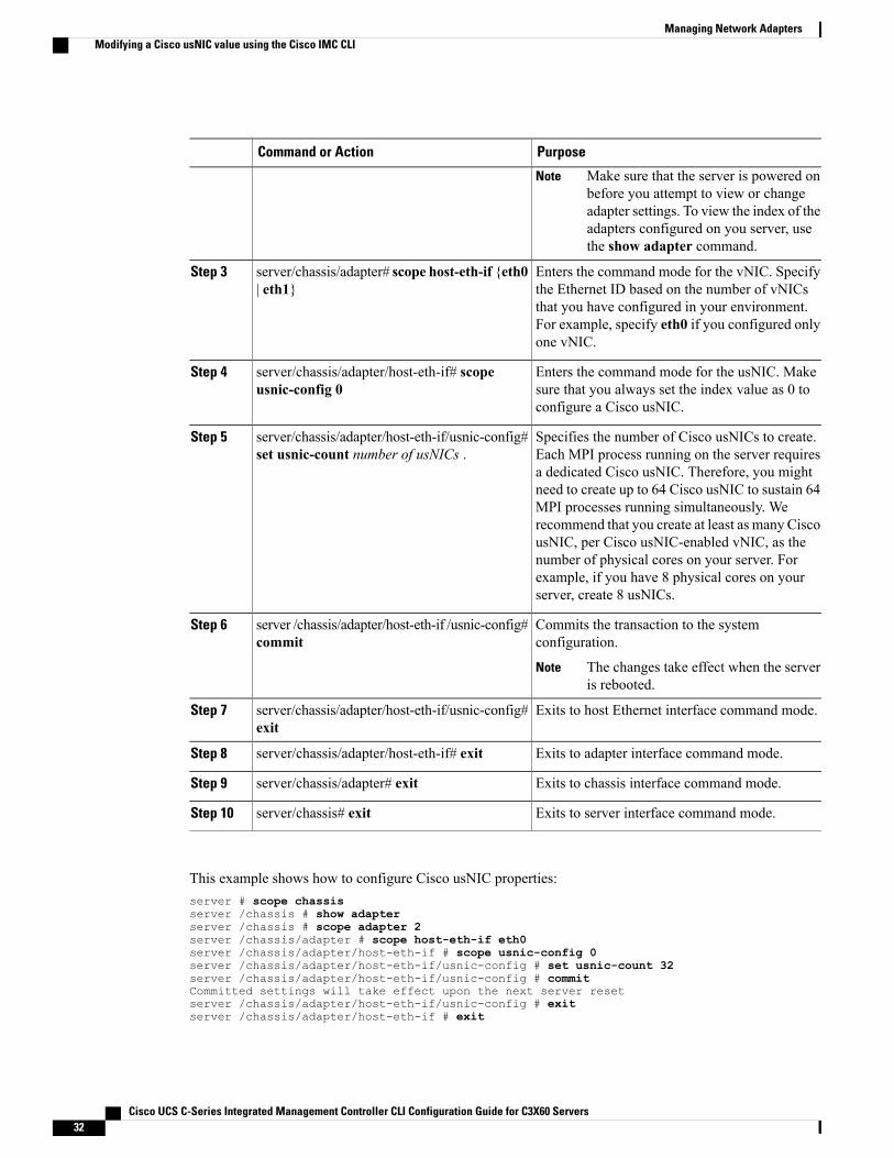
PurposeCommand or Action
Make sure that the server is powered onbefore you attempt to view or changeadapter settings. To view the index of theadapters configured on you server, usethe show adapter command.
Note
Enters the command mode for the vNIC. Specifythe Ethernet ID based on the number of vNICs
server/chassis/adapter# scope host-eth-if {eth0| eth1}
Step 3
that you have configured in your environment.For example, specify eth0 if you configured onlyone vNIC.
Enters the command mode for the usNIC. Makesure that you always set the index value as 0 toconfigure a Cisco usNIC.
server/chassis/adapter/host-eth-if# scopeusnic-config 0
Step 4
Specifies the number of Cisco usNICs to create.Each MPI process running on the server requires
server/chassis/adapter/host-eth-if/usnic-config#set usnic-count number of usNICs .
Step 5
a dedicated Cisco usNIC. Therefore, you mightneed to create up to 64 Cisco usNIC to sustain 64MPI processes running simultaneously. Werecommend that you create at least as many CiscousNIC, per Cisco usNIC-enabled vNIC, as thenumber of physical cores on your server. Forexample, if you have 8 physical cores on yourserver, create 8 usNICs.
Commits the transaction to the systemconfiguration.
server /chassis/adapter/host-eth-if /usnic-config#commit
Step 6
The changes take effect when the serveris rebooted.
Note
Exits to host Ethernet interface command mode.server/chassis/adapter/host-eth-if/usnic-config#exit
Step 7
Exits to adapter interface command mode.server/chassis/adapter/host-eth-if# exitStep 8
Exits to chassis interface command mode.server/chassis/adapter# exitStep 9
Exits to server interface command mode.server/chassis# exitStep 10
This example shows how to configure Cisco usNIC properties:server # scope chassisserver /chassis # show adapterserver /chassis # scope adapter 2server /chassis/adapter # scope host-eth-if eth0server /chassis/adapter/host-eth-if # scope usnic-config 0server /chassis/adapter/host-eth-if/usnic-config # set usnic-count 32server /chassis/adapter/host-eth-if/usnic-config # commitCommitted settings will take effect upon the next server resetserver /chassis/adapter/host-eth-if/usnic-config # exitserver /chassis/adapter/host-eth-if # exit
Cisco UCS C-Series Integrated Management Controller CLI Configuration Guide for C3X60 Servers32
Managing Network AdaptersModifying a Cisco usNIC value using the Cisco IMC CLI
server /chassis/adapter # exitserver /chassis # exitserver # exit
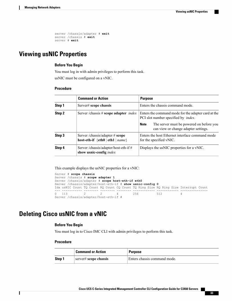
Viewing usNIC Properties
Before You Begin
You must log in with admin privileges to perform this task.
usNIC must be configured on a vNIC.
Procedure
PurposeCommand or Action
Enters the chassis command mode.Server# scope chassisStep 1
Enters the commandmode for the adapter card at thePCI slot number specified by index.
Server /chassis # scope adapter indexStep 2
The server must be powered on before youcan view or change adapter settings.
Note
Enters the host Ethernet interface command modefor the specified vNIC.
Server /chassis/adapter # scopehost-eth-if {eth0 | eth1 | name}
Step 3
Displays the usNIC properties for a vNIC.Server /chassis/adapter/host-eth-if #show usnic-config index
Step 4
This example displays the usNIC properties for a vNIC:Server # scope chassisServer /chassis # scope adapter 1Server /chassis/adapter # scope host-eth-if eth0Server /chassis/adapter/host-eth-if # show usnic-config 0Idx usNIC Count TQ Count RQ Count CQ Count TQ Ring Size RQ Ring Size Interrupt Count--- ----------- -------- -------- -------- ------------ ------------ ---------------0 113 2 2 4 256 512 4Server /chassis/adapter/host-eth-if #
Deleting Cisco usNIC from a vNIC
Before You Begin
You must log in to Cisco IMC CLI with admin privileges to perform this task.
Procedure
PurposeCommand or Action
Enters chassis command mode.server# scope chassisStep 1
Cisco UCS C-Series Integrated Management Controller CLI Configuration Guide for C3X60 Servers 33
Managing Network AdaptersViewing usNIC Properties

PurposeCommand or Action
Enters the command mode for the adapter card at the PCIslot number specified by index.
server/chassis# scope adapterindex
Step 2
Make sure that the server is powered on before youattempt to view or change adapter settings. To viewthe index of the adapters configured on you server,use the show adapter command.
Note
Enters the commandmode for the vNIC. Specify the EthernetID based on the number of vNICs that you have configured
server/chassis/adapter# scopehost-eth-if {eth0 | eth1}
Step 3
in your environment. For example, specify eth0 if youconfigured only one vNIC.
Deletes the Cisco usNIC configuration for the vNIC.Server/chassis/adapter/host-eth-if#delete usnic-config 0
Step 4
Commits the transaction to the system configurationServer/chassis/adapter/host-eth-if#commit
Step 5
The changes take effect when the server isrebooted.
Note
This example shows how to delete the Cisco usNIC configuration for a vNIC:server # scope chassisserver/chassis # show adapterserver/chassis # scope adapter 1server/chassis/adapter # scope host-eth-if eth0server/chassis/adapter/host-eth-if # delete usnic-config 0server/chassis/host-eth-if/iscsi-boot *# commitNew host-eth-if settings will take effect upon the next adapter reboot
server/chassis/host-eth-if/usnic-config #
Configuring iSCSI Boot Capability
Configuring iSCSI Boot Capability for vNICsWhen the rack-servers are configured in a standalone mode, and when the VIC adapters are directly attachedto the Nexus 5000 and Nexus 6000 family of switches, you can configure these VIC adapters to boot theservers remotely from iSCSI storage targets. You can configure Ethernet vNICs to enable a rack server toload the host OS image from remote iSCSI target devices.
To configure the iSCSI boot capability on a vNIC:
• You must log in with admin privileges to perform this task.
• To configure a vNIC to boot a server remotely from an iSCSI storage target, you must enable the PXEboot option on the vNIC.
Cisco UCS C-Series Integrated Management Controller CLI Configuration Guide for C3X60 Servers34
Managing Network AdaptersConfiguring iSCSI Boot Capability
You can configure a maximum of 2 iSCSI vNICs for each host.Note
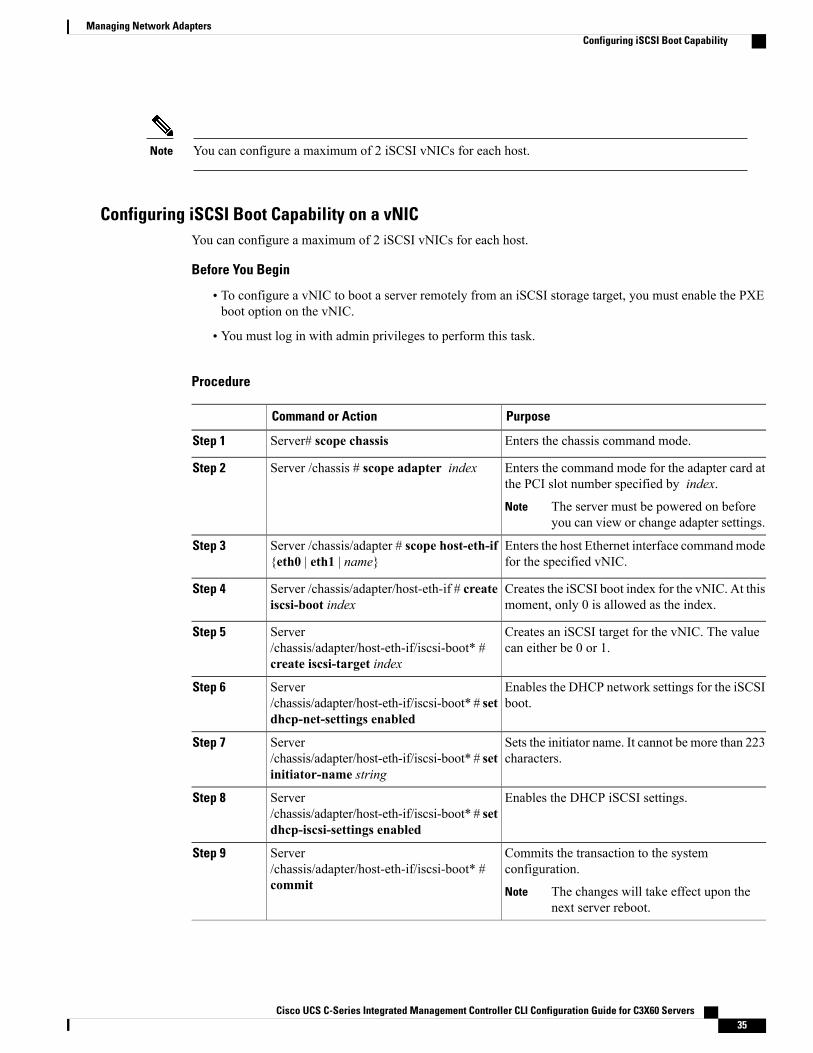
Configuring iSCSI Boot Capability on a vNICYou can configure a maximum of 2 iSCSI vNICs for each host.
Before You Begin
• To configure a vNIC to boot a server remotely from an iSCSI storage target, you must enable the PXEboot option on the vNIC.
• You must log in with admin privileges to perform this task.
Procedure
PurposeCommand or Action
Enters the chassis command mode.Server# scope chassisStep 1
Enters the command mode for the adapter card atthe PCI slot number specified by index.
Server /chassis # scope adapter indexStep 2
The server must be powered on beforeyou can view or change adapter settings.
Note
Enters the host Ethernet interface commandmodefor the specified vNIC.
Server /chassis/adapter # scope host-eth-if{eth0 | eth1 | name}
Step 3
Creates the iSCSI boot index for the vNIC. At thismoment, only 0 is allowed as the index.
Server /chassis/adapter/host-eth-if # createiscsi-boot index
Step 4
Creates an iSCSI target for the vNIC. The valuecan either be 0 or 1.
Server/chassis/adapter/host-eth-if/iscsi-boot* #create iscsi-target index
Step 5
Enables the DHCP network settings for the iSCSIboot.
Server/chassis/adapter/host-eth-if/iscsi-boot* # setdhcp-net-settings enabled
Step 6
Sets the initiator name. It cannot be more than 223characters.
Server/chassis/adapter/host-eth-if/iscsi-boot* # setinitiator-name string
Step 7
Enables the DHCP iSCSI settings.Server/chassis/adapter/host-eth-if/iscsi-boot* # setdhcp-iscsi-settings enabled
Step 8
Commits the transaction to the systemconfiguration.
Server/chassis/adapter/host-eth-if/iscsi-boot* #commit
Step 9
The changes will take effect upon thenext server reboot.
Note
Cisco UCS C-Series Integrated Management Controller CLI Configuration Guide for C3X60 Servers 35
Managing Network AdaptersConfiguring iSCSI Boot Capability
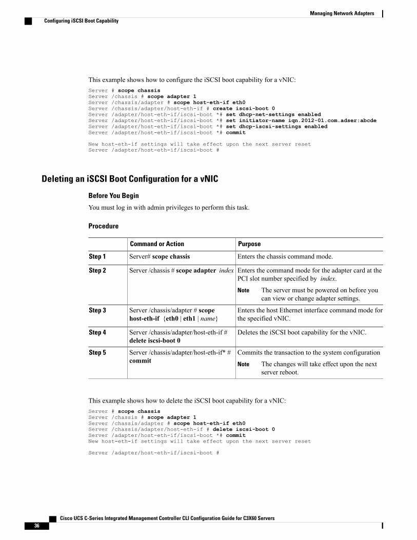
This example shows how to configure the iSCSI boot capability for a vNIC:Server # scope chassisServer /chassis # scope adapter 1Server /chassis/adapter # scope host-eth-if eth0Server /chassis/adapter/host-eth-if # create iscsi-boot 0Server /adapter/host-eth-if/iscsi-boot *# set dhcp-net-settings enabledServer /adapter/host-eth-if/iscsi-boot *# set initiator-name iqn.2012-01.com.adser:abcdeServer /adapter/host-eth-if/iscsi-boot *# set dhcp-iscsi-settings enabledServer /adapter/host-eth-if/iscsi-boot *# commit
New host-eth-if settings will take effect upon the next server resetServer /adapter/host-eth-if/iscsi-boot #
Deleting an iSCSI Boot Configuration for a vNIC
Before You Begin
You must log in with admin privileges to perform this task.
Procedure
PurposeCommand or Action
Enters the chassis command mode.Server# scope chassisStep 1
Enters the command mode for the adapter card at thePCI slot number specified by index.
Server /chassis # scope adapter indexStep 2
The server must be powered on before youcan view or change adapter settings.
Note
Enters the host Ethernet interface command mode forthe specified vNIC.
Server /chassis/adapter # scopehost-eth-if {eth0 | eth1 | name}
Step 3
Deletes the iSCSI boot capability for the vNIC.Server /chassis/adapter/host-eth-if #delete iscsi-boot 0
Step 4
Commits the transaction to the system configurationServer /chassis/adapter/host-eth-if* #commit
Step 5
The changes will take effect upon the nextserver reboot.
Note
This example shows how to delete the iSCSI boot capability for a vNIC:Server # scope chassisServer /chassis # scope adapter 1Server /chassis/adapter # scope host-eth-if eth0Server /chassis/adapter/host-eth-if # delete iscsi-boot 0Server /adapter/host-eth-if/iscsi-boot *# commitNew host-eth-if settings will take effect upon the next server reset
Server /adapter/host-eth-if/iscsi-boot #
Cisco UCS C-Series Integrated Management Controller CLI Configuration Guide for C3X60 Servers36
Managing Network AdaptersConfiguring iSCSI Boot Capability
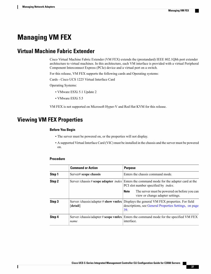
Managing VM FEX
Virtual Machine Fabric ExtenderCisco Virtual Machine Fabric Extender (VM FEX) extends the (prestandard) IEEE 802.1Qbh port extenderarchitecture to virtual machines. In this architecture, each VM interface is provided with a virtual PeripheralComponent Interconnect Express (PCIe) device and a virtual port on a switch.
For this release, VM FEX supports the following cards and Operating systems:
Cards - Cisco UCS 1225 Virtual Interface Card
Operating Systems:
• VMware ESXi 5.1 Update 2
• VMware ESXi 5.5
VM FEX is not supported on Microsoft Hyper-V and Red Hat KVM for this release.
Viewing VM FEX Properties
Before You Begin
• The server must be powered on, or the properties will not display.
• A supported Virtual Interface Card (VIC) must be installed in the chassis and the server must be poweredon.
Procedure
PurposeCommand or Action
Enters the chassis command mode.Server# scope chassisStep 1
Enters the command mode for the adapter card at thePCI slot number specified by index.
Server /chassis # scope adapter indexStep 2
The server must be powered on before you canview or change adapter settings.
Note
Displays the general VM FEX properties. For fielddescriptions, see General Properties Settings, on page39.
Server /chassis/adapter # show vmfex[detail]
Step 3
Enters the command mode for the specified VM FEXinterface.
Server /chassis/adapter # scope vmfexname
Step 4
Cisco UCS C-Series Integrated Management Controller CLI Configuration Guide for C3X60 Servers 37
Managing Network AdaptersManaging VM FEX
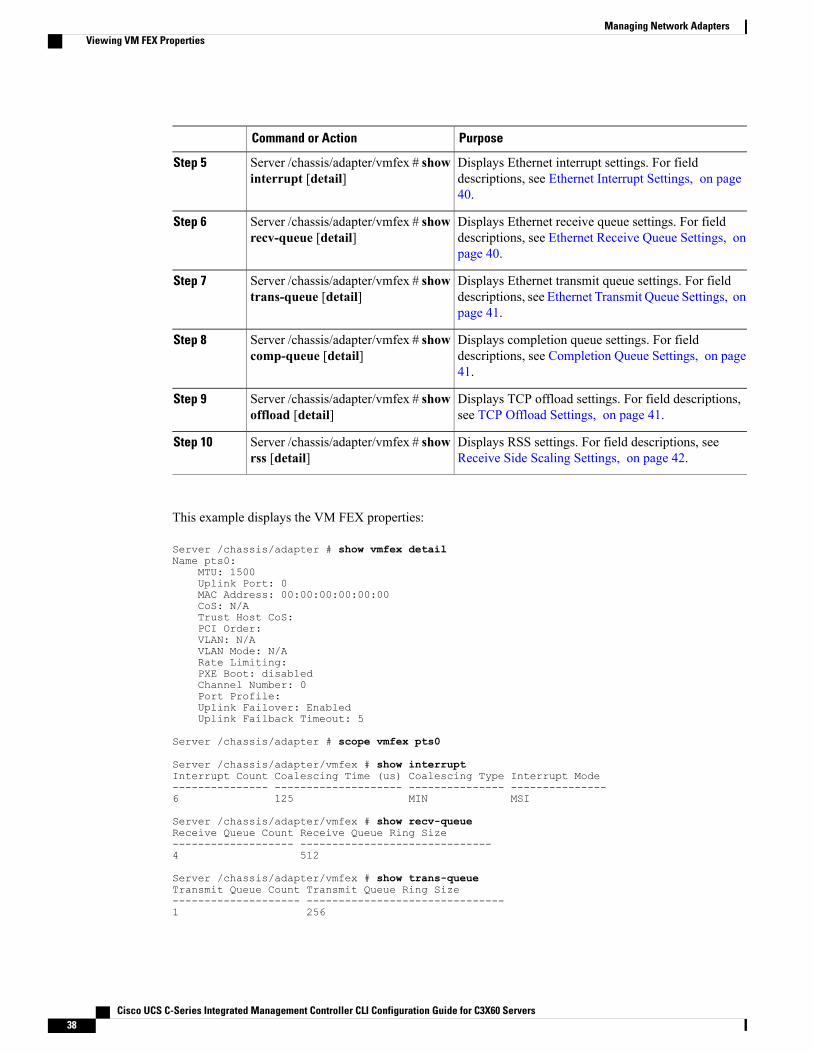
PurposeCommand or Action
Displays Ethernet interrupt settings. For fielddescriptions, see Ethernet Interrupt Settings, on page40.
Server /chassis/adapter/vmfex # showinterrupt [detail]
Step 5
Displays Ethernet receive queue settings. For fielddescriptions, see Ethernet Receive Queue Settings, onpage 40.
Server /chassis/adapter/vmfex # showrecv-queue [detail]
Step 6
Displays Ethernet transmit queue settings. For fielddescriptions, see Ethernet Transmit Queue Settings, onpage 41.
Server /chassis/adapter/vmfex # showtrans-queue [detail]
Step 7
Displays completion queue settings. For fielddescriptions, see Completion Queue Settings, on page41.
Server /chassis/adapter/vmfex # showcomp-queue [detail]
Step 8
Displays TCP offload settings. For field descriptions,see TCP Offload Settings, on page 41.
Server /chassis/adapter/vmfex # showoffload [detail]
Step 9
Displays RSS settings. For field descriptions, seeReceive Side Scaling Settings, on page 42.
Server /chassis/adapter/vmfex # showrss [detail]
Step 10
This example displays the VM FEX properties:
Server /chassis/adapter # show vmfex detailName pts0:
MTU: 1500Uplink Port: 0MAC Address: 00:00:00:00:00:00CoS: N/ATrust Host CoS:PCI Order:VLAN: N/AVLAN Mode: N/ARate Limiting:PXE Boot: disabledChannel Number: 0Port Profile:Uplink Failover: EnabledUplink Failback Timeout: 5
Server /chassis/adapter # scope vmfex pts0
Server /chassis/adapter/vmfex # show interruptInterrupt Count Coalescing Time (us) Coalescing Type Interrupt Mode--------------- -------------------- --------------- ---------------6 125 MIN MSI
Server /chassis/adapter/vmfex # show recv-queueReceive Queue Count Receive Queue Ring Size------------------- ------------------------------4 512
Server /chassis/adapter/vmfex # show trans-queueTransmit Queue Count Transmit Queue Ring Size-------------------- -------------------------------1 256
Cisco UCS C-Series Integrated Management Controller CLI Configuration Guide for C3X60 Servers38
Managing Network AdaptersViewing VM FEX Properties
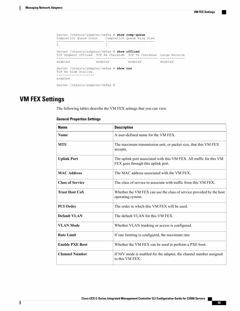
Server /chassis/adapter/vmfex # show comp-queueCompletion Queue Count Completion Queue Ring Size------------------------- --------------------------5 1
Server /chassis/adapter/vmfex # show offloadTCP Segment Offload TCP Rx Checksum TCP Tx Checksum Large Receive-------------------- ---------------- ---------------- -------------enabled enabled enabled enabled
Server /chassis/adapter/vmfex # show rssTCP Rx Side Scaling--------------------enabled
Server /chassis/adapter/vmfex #
VM FEX SettingsThe following tables describe the VM FEX settings that you can view.
General Properties Settings
DescriptionName
A user-defined name for the VM FEX.Name
The maximum transmission unit, or packet size, that this VM FEXaccepts.
MTU
The uplink port associated with this VM FEX. All traffic for this VMFEX goes through this uplink port.
Uplink Port
The MAC address associated with the VM FEX.MAC Address
The class of service to associate with traffic from this VM FEX.Class of Service
Whether the VM FEX can use the class of service provided by the hostoperating system.
Trust Host CoS
The order in which this VM FEX will be used.PCI Order
The default VLAN for this VM FEX.Default VLAN
Whether VLAN trunking or access is configured.VLANMode
If rate limiting is configured, the maximum rate.Rate Limit
Whether the VM FEX can be used to perform a PXE boot.Enable PXE Boot
If NIV mode is enabled for the adapter, the channel number assignedto this VM FEX.
Channel Number
Cisco UCS C-Series Integrated Management Controller CLI Configuration Guide for C3X60 Servers 39
Managing Network AdaptersVM FEX Settings
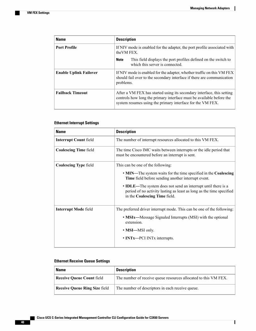
DescriptionName
If NIV mode is enabled for the adapter, the port profile associated withtheVM FEX.
This field displays the port profiles defined on the switch towhich this server is connected.
Note
Port Profile
If NIVmode is enabled for the adapter, whether traffic on this VM FEXshould fail over to the secondary interface if there are communicationproblems.
Enable Uplink Failover
After a VM FEX has started using its secondary interface, this settingcontrols how long the primary interface must be available before thesystem resumes using the primary interface for the VM FEX.
Failback Timeout
Ethernet Interrupt Settings
DescriptionName
The number of interrupt resources allocated to this VM FEX.Interrupt Count field
The time Cisco IMC waits between interrupts or the idle period thatmust be encountered before an interrupt is sent.
Coalescing Time field
This can be one of the following:
•MIN—The system waits for the time specified in the CoalescingTime field before sending another interrupt event.
• IDLE—The system does not send an interrupt until there is aperiod of no activity lasting as least as long as the time specifiedin the Coalescing Time field.
Coalescing Type field
The preferred driver interrupt mode. This can be one of the following:
•MSIx—Message Signaled Interrupts (MSI) with the optionalextension.
•MSI—MSI only.
• INTx—PCI INTx interrupts.
Interrupt Mode field
Ethernet Receive Queue Settings
DescriptionName
The number of receive queue resources allocated to this VM FEX.Receive Queue Count field
The number of descriptors in each receive queue.Receive Queue Ring Size field
Cisco UCS C-Series Integrated Management Controller CLI Configuration Guide for C3X60 Servers40
Managing Network AdaptersVM FEX Settings
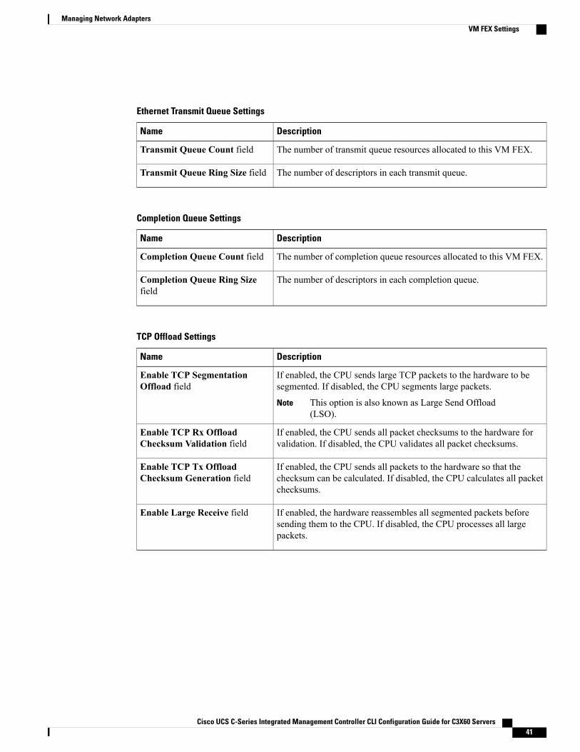
Ethernet Transmit Queue Settings
DescriptionName
The number of transmit queue resources allocated to this VM FEX.Transmit Queue Count field
The number of descriptors in each transmit queue.Transmit Queue Ring Size field
Completion Queue Settings
DescriptionName
The number of completion queue resources allocated to this VM FEX.Completion Queue Count field
The number of descriptors in each completion queue.Completion Queue Ring Sizefield
TCP Offload Settings
DescriptionName
If enabled, the CPU sends large TCP packets to the hardware to besegmented. If disabled, the CPU segments large packets.
This option is also known as Large Send Offload(LSO).
Note
Enable TCP SegmentationOffload field
If enabled, the CPU sends all packet checksums to the hardware forvalidation. If disabled, the CPU validates all packet checksums.
Enable TCP Rx OffloadChecksum Validation field
If enabled, the CPU sends all packets to the hardware so that thechecksum can be calculated. If disabled, the CPU calculates all packetchecksums.
Enable TCP Tx OffloadChecksum Generation field
If enabled, the hardware reassembles all segmented packets beforesending them to the CPU. If disabled, the CPU processes all largepackets.
Enable Large Receive field
Cisco UCS C-Series Integrated Management Controller CLI Configuration Guide for C3X60 Servers 41
Managing Network AdaptersVM FEX Settings
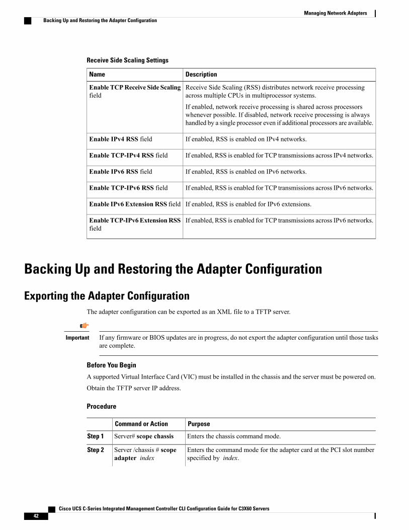
Receive Side Scaling Settings
DescriptionName
Receive Side Scaling (RSS) distributes network receive processingacross multiple CPUs in multiprocessor systems.
If enabled, network receive processing is shared across processorswhenever possible. If disabled, network receive processing is alwayshandled by a single processor even if additional processors are available.
Enable TCPReceive Side Scalingfield
If enabled, RSS is enabled on IPv4 networks.Enable IPv4 RSS field
If enabled, RSS is enabled for TCP transmissions across IPv4 networks.Enable TCP-IPv4 RSS field
If enabled, RSS is enabled on IPv6 networks.Enable IPv6 RSS field
If enabled, RSS is enabled for TCP transmissions across IPv6 networks.Enable TCP-IPv6 RSS field
If enabled, RSS is enabled for IPv6 extensions.Enable IPv6 Extension RSS field
If enabled, RSS is enabled for TCP transmissions across IPv6 networks.Enable TCP-IPv6ExtensionRSSfield
Backing Up and Restoring the Adapter Configuration
Exporting the Adapter ConfigurationThe adapter configuration can be exported as an XML file to a TFTP server.
If any firmware or BIOS updates are in progress, do not export the adapter configuration until those tasksare complete.
Important
Before You Begin
A supported Virtual Interface Card (VIC) must be installed in the chassis and the server must be powered on.
Obtain the TFTP server IP address.
Procedure
PurposeCommand or Action
Enters the chassis command mode.Server# scope chassisStep 1
Enters the command mode for the adapter card at the PCI slot numberspecified by index.
Server /chassis # scopeadapter index
Step 2
Cisco UCS C-Series Integrated Management Controller CLI Configuration Guide for C3X60 Servers42
Managing Network AdaptersBacking Up and Restoring the Adapter Configuration

PurposeCommand or Action
The server must be powered on before you can view or changeadapter settings.
Note
Starts the export operation. The adapter configuration file will be storedat the specified path and filename on the remote server at the specifiedIP address. The protocol can be one of the following:
Server /chassis/adapter #export-vnic protocolremote server IP address
Step 3
• TFTP
• FTP
• SFTP
• SCP
• HTTP
The Cisco UCS C-Series server now supports fingerprintconfirmation of the server when you update firmware througha remote server. This option is available only if you chooseSCP or SFTP as the remote server type.
If you chose SCP or SFTP as the remote server type whileperforming this action, a prompt with themessage Server (RSA)key fingerprint is <server_finger_print _ID> Do you wish tocontinue? Click y or n depending on the authenticity of theserver fingerprint.
The fingerprint is based on the host's public key and helps youto identify or verify the host you are connecting to.
Note
This example exports the configuration of adapter 1:Server# scope chassisServer /chassis # scope adapter 1Server /chassis/adapter # export-vnic ftp 192.0.20.34 //test/dnld-ucs-k9-bundle.1.0.2h.binServer /chassis/adapter #
Importing the Adapter Configuration
If any firmware or BIOS updates are in progress, do not import the adapter configuration until those tasksare complete.
Important
Before You Begin
You must log in with admin privileges to perform this task.
Cisco UCS C-Series Integrated Management Controller CLI Configuration Guide for C3X60 Servers 43
Managing Network AdaptersImporting the Adapter Configuration
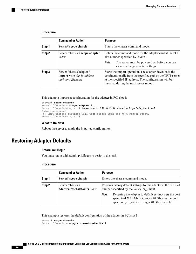
Procedure
PurposeCommand or Action
Enters the chassis command mode.Server# scope chassisStep 1
Enters the command mode for the adapter card at the PCIslot number specified by index.
Server /chassis # scope adapterindex
Step 2
The server must be powered on before you canview or change adapter settings.
Note
Starts the import operation. The adapter downloads theconfiguration file from the specified path on the TFTP server
Server /chassis/adapter #import-vnic tftp-ip-addresspath-and-filename
Step 3
at the specified IP address. The configuration will beinstalled during the next server reboot.
This example imports a configuration for the adapter in PCI slot 1:Server# scope chassisServer /chassis # scope adapter 1Server /chassis/adapter # import-vnic 192.0.2.34 /ucs/backups/adapter4.xmlImport succeeded.New VNIC adapter settings will take effect upon the next server reset.Server /chassis/adapter #
What to Do Next
Reboot the server to apply the imported configuration.
Restoring Adapter Defaults
Before You Begin
You must log in with admin privileges to perform this task.
Procedure
PurposeCommand or Action
Enters the chassis command mode.Server# scope chassisStep 1
Restores factory default settings for the adapter at the PCI slotnumber specified by the index argument.
Server /chassis #adapter-reset-defaults index
Step 2
Resetting the adapter to default settings sets the portspeed to 4 X 10 Gbps. Choose 40 Gbps as the portspeed only if you are using a 40 Gbps switch.
Note
This example restores the default configuration of the adapter in PCI slot 1:Server# scope chassisServer /chassis # adapter-reset-defaults 1
Cisco UCS C-Series Integrated Management Controller CLI Configuration Guide for C3X60 Servers44
Managing Network AdaptersRestoring Adapter Defaults
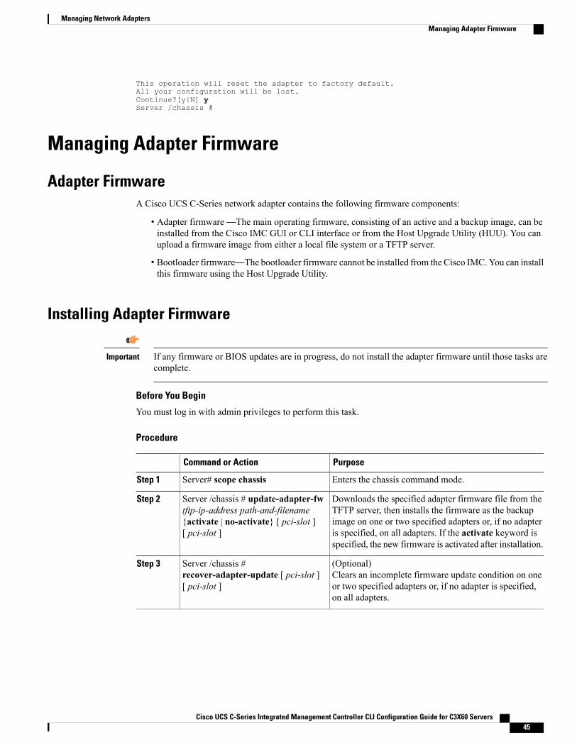
This operation will reset the adapter to factory default.All your configuration will be lost.Continue?[y|N] yServer /chassis #
Managing Adapter Firmware
Adapter FirmwareA Cisco UCS C-Series network adapter contains the following firmware components:
• Adapter firmware—The main operating firmware, consisting of an active and a backup image, can beinstalled from the Cisco IMC GUI or CLI interface or from the Host Upgrade Utility (HUU). You canupload a firmware image from either a local file system or a TFTP server.
• Bootloader firmware—The bootloader firmware cannot be installed from the Cisco IMC. You can installthis firmware using the Host Upgrade Utility.
Installing Adapter Firmware
If any firmware or BIOS updates are in progress, do not install the adapter firmware until those tasks arecomplete.
Important
Before You Begin
You must log in with admin privileges to perform this task.
Procedure
PurposeCommand or Action
Enters the chassis command mode.Server# scope chassisStep 1
Downloads the specified adapter firmware file from theTFTP server, then installs the firmware as the backup
Server /chassis # update-adapter-fwtftp-ip-address path-and-filename
Step 2
image on one or two specified adapters or, if no adapter{activate | no-activate} [ pci-slot ][ pci-slot ] is specified, on all adapters. If the activate keyword is
specified, the new firmware is activated after installation.
(Optional)Clears an incomplete firmware update condition on oneor two specified adapters or, if no adapter is specified,on all adapters.
Server /chassis #recover-adapter-update [ pci-slot ][ pci-slot ]
Step 3
Cisco UCS C-Series Integrated Management Controller CLI Configuration Guide for C3X60 Servers 45
Managing Network AdaptersManaging Adapter Firmware
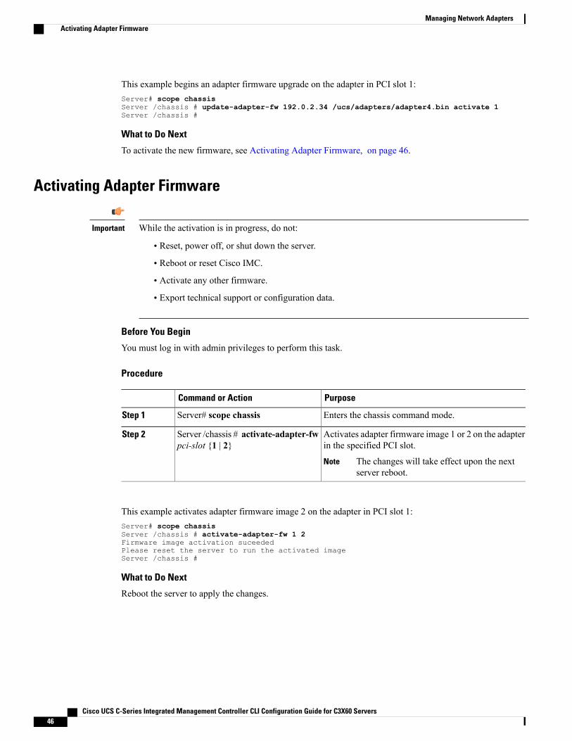
This example begins an adapter firmware upgrade on the adapter in PCI slot 1:Server# scope chassisServer /chassis # update-adapter-fw 192.0.2.34 /ucs/adapters/adapter4.bin activate 1Server /chassis #
What to Do Next
To activate the new firmware, see Activating Adapter Firmware, on page 46.
Activating Adapter Firmware
While the activation is in progress, do not:Important
• Reset, power off, or shut down the server.
• Reboot or reset Cisco IMC.
• Activate any other firmware.
• Export technical support or configuration data.
Before You Begin
You must log in with admin privileges to perform this task.
Procedure
PurposeCommand or Action
Enters the chassis command mode.Server# scope chassisStep 1
Activates adapter firmware image 1 or 2 on the adapterin the specified PCI slot.
Server /chassis # activate-adapter-fwpci-slot {1 | 2}
Step 2
The changes will take effect upon the nextserver reboot.
Note
This example activates adapter firmware image 2 on the adapter in PCI slot 1:Server# scope chassisServer /chassis # activate-adapter-fw 1 2Firmware image activation suceededPlease reset the server to run the activated imageServer /chassis #
What to Do Next
Reboot the server to apply the changes.
Cisco UCS C-Series Integrated Management Controller CLI Configuration Guide for C3X60 Servers46
Managing Network AdaptersActivating Adapter Firmware