Embed Size (px)
Citation preview
C H A P T E R
4-1Catalyst 2950 Desktop Switch Software Configuration Guide
78-11380-01
4Managing Switches
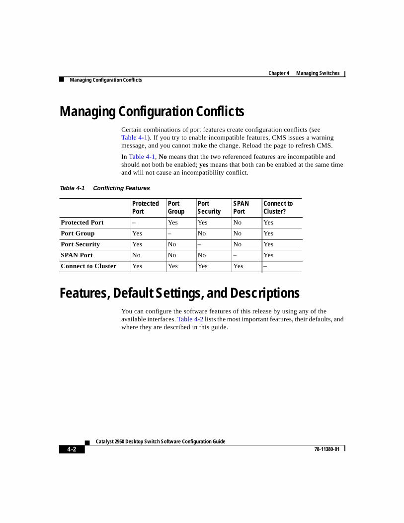
This chapter describes how to use the device-management features of the ClusterManagement Suite (CMS). The features described in this chapter can all beimplemented through Visual Switch Manager (VSM), the web-based interface formanaging standalone switches, or through Cluster Manager. If you needinformation on how to group your switches into a cluster, seeChapter 3,“Creating and Managing Clusters.”
This chapter describes two ways to configure switches:
• By using CMS windows to monitor and configure switches and ports.
How-to procedures for using the windows are in the online help.
• By using the Cisco IOS command-line interface (CLI).
CLI procedures are included for many tasks in this chapter. There are somefeatures that can only be implemented by using the CLI.
Finding More Information About IOS CommandsThis guide describes only the IOS commands that have been created orchanged for the Catalyst 2950 switches. These commands are furtherdescribed in theCatalyst 2950 Desktop Switch Command Reference.
For information on other IOS Release 12.0 commands, refer to the Cisco IOSRelease 12.0 documentation set available on Cisco.com.
Chapter 4 Managing SwitchesManaging Configuration Conflicts
4-2Catalyst 2950 Desktop Switch Software Configuration Guide
78-11380-01
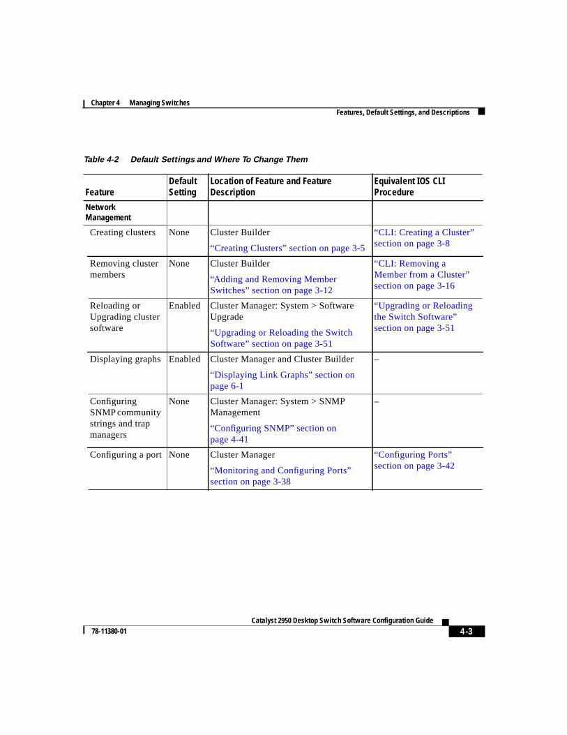
Managing Configuration ConflictsCertain combinations of port features create configuration conflicts (seeTable 4-1). If you try to enable incompatible features, CMS issues a warningmessage, and you cannot make the change. Reload the page to refresh CMS.
In Table 4-1, No means that the two referenced features are incompatible andshould not both be enabled;yesmeans that both can be enabled at the same timeand will not cause an incompatibility conflict.
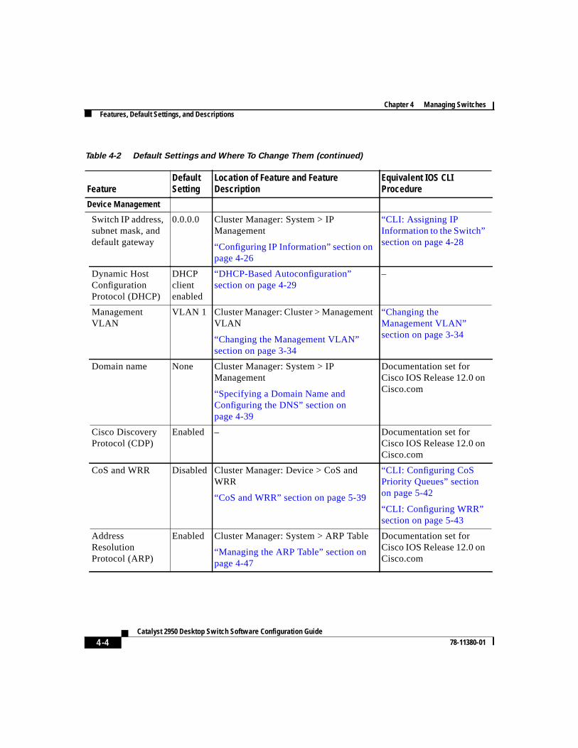
Features, Default Settings, and DescriptionsYou can configure the software features of this release by using any of theavailable interfaces.Table 4-2lists the most important features, their defaults, andwhere they are described in this guide.
Table 4-1 Conflicting Features
ProtectedPort
PortGroup
PortSecurity
SPANPort
Connect toCluster?
Protected Port – Yes Yes No Yes
Port Group Yes – No No Yes
Port Security Yes No – No Yes
SPAN Port No No No – Yes
Connect to Cluster Yes Yes Yes Yes –
4-3Catalyst 2950 Desktop Switch Software Configuration Guide
78-11380-01
Chapter 4 Managing SwitchesFeatures, Default Settings, and Descriptions
Table 4-2 Default Settings and Where To Change Them
FeatureDefaultSetting
Location of Feature and FeatureDescription
Equivalent IOS CLIProcedure
NetworkManagement
Creating clusters None Cluster Builder
“Creating Clusters” section on page 3-5
“CLI: Creating a Cluster”section on page 3-8
Removing clustermembers
None Cluster Builder
“Adding and Removing MemberSwitches” section on page 3-12
“CLI: Removing aMember from a Cluster”section on page 3-16
Reloading orUpgrading clustersoftware
Enabled Cluster Manager: System > SoftwareUpgrade
“Upgrading or Reloading the SwitchSoftware” section on page 3-51
“Upgrading or Reloadingthe Switch Software”section on page 3-51
Displaying graphs Enabled Cluster Manager and Cluster Builder
“Displaying Link Graphs” section onpage 6-1
–
ConfiguringSNMP communitystrings and trapmanagers
None Cluster Manager: System > SNMPManagement
“Configuring SNMP” section onpage 4-41
–
Configuring a port None Cluster Manager
“Monitoring and Configuring Ports”section on page 3-38
“Configuring Ports”section on page 3-42
Chapter 4 Managing SwitchesFeatures, Default Settings, and Descriptions
4-4Catalyst 2950 Desktop Switch Software Configuration Guide
78-11380-01
Device Management
Switch IP address,subnet mask, anddefault gateway
0.0.0.0 Cluster Manager: System > IPManagement
“Configuring IP Information” section onpage 4-26
“CLI: Assigning IPInformation to the Switch”section on page 4-28
Dynamic HostConfigurationProtocol (DHCP)
DHCPclientenabled
“DHCP-Based Autoconfiguration”section on page 4-29
–
ManagementVLAN
VLAN 1 Cluster Manager: Cluster > ManagementVLAN
“Changing the Management VLAN”section on page 3-34
“Changing theManagement VLAN”section on page 3-34
Domain name None Cluster Manager: System > IPManagement
“Specifying a Domain Name andConfiguring the DNS” section onpage 4-39
Documentation set forCisco IOS Release 12.0 onCisco.com
Cisco DiscoveryProtocol (CDP)
Enabled – Documentation set forCisco IOS Release 12.0 onCisco.com
CoS and WRR Disabled Cluster Manager: Device > CoS andWRR
“CoS and WRR” section on page 5-39
“CLI: Configuring CoSPriority Queues” sectionon page 5-42
“CLI: Configuring WRR”section on page 5-43
AddressResolutionProtocol (ARP)
Enabled Cluster Manager: System > ARP Table
“Managing the ARP Table” section onpage 4-47
Documentation set forCisco IOS Release 12.0 onCisco.com
Table 4-2 Default Settings and Where To Change Them (continued)
FeatureDefaultSetting
Location of Feature and FeatureDescription
Equivalent IOS CLIProcedure
4-5Catalyst 2950 Desktop Switch Software Configuration Guide
78-11380-01
Chapter 4 Managing SwitchesFeatures, Default Settings, and Descriptions
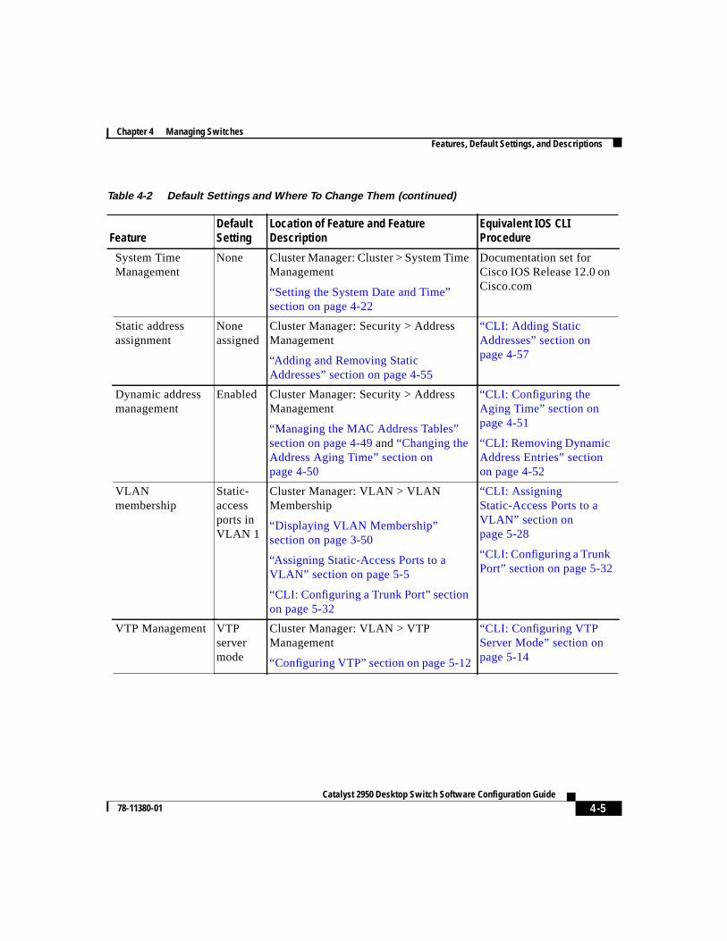
System TimeManagement
None Cluster Manager: Cluster > System TimeManagement
“Setting the System Date and Time”section on page 4-22
Documentation set forCisco IOS Release 12.0 onCisco.com
Static addressassignment
Noneassigned
Cluster Manager: Security > AddressManagement
“Adding and Removing StaticAddresses” section on page 4-55
“CLI: Adding StaticAddresses” section onpage 4-57
Dynamic addressmanagement
Enabled Cluster Manager: Security > AddressManagement
“Managing the MAC Address Tables”section on page 4-49and“Changing theAddress Aging Time” section onpage 4-50
“CLI: Configuring theAging Time” section onpage 4-51
“CLI: Removing DynamicAddress Entries” sectionon page 4-52
VLANmembership
Static-accessports inVLAN 1
Cluster Manager: VLAN > VLANMembership
“Displaying VLAN Membership”section on page 3-50
“Assigning Static-Access Ports to aVLAN” section on page 5-5
“CLI: Configuring a Trunk Port” sectionon page 5-32
“CLI: AssigningStatic-Access Ports to aVLAN” section onpage 5-28
“CLI: Configuring a TrunkPort” section on page 5-32
VTP Management VTPservermode
Cluster Manager: VLAN > VTPManagement
“Configuring VTP” section on page 5-12
“CLI: Configuring VTPServer Mode” section onpage 5-14
Table 4-2 Default Settings and Where To Change Them (continued)
FeatureDefaultSetting
Location of Feature and FeatureDescription
Equivalent IOS CLIProcedure
Chapter 4 Managing SwitchesFeatures, Default Settings, and Descriptions
4-6Catalyst 2950 Desktop Switch Software Configuration Guide
78-11380-01
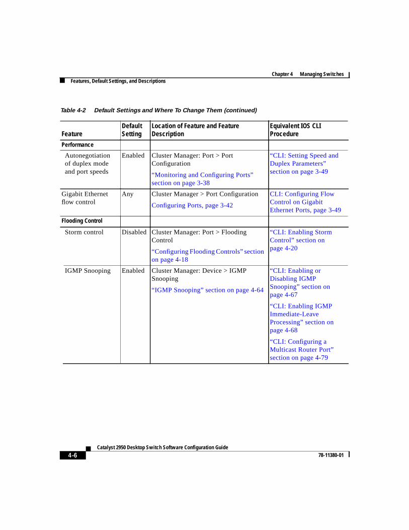
Performance
Autonegotiationof duplex modeand port speeds
Enabled Cluster Manager: Port > PortConfiguration
“Monitoring and Configuring Ports”section on page 3-38
“CLI: Setting Speed andDuplex Parameters”section on page 3-49
Gigabit Ethernetflow control
Any Cluster Manager > Port Configuration
Configuring Ports, page 3-42
CLI: Configuring FlowControl on GigabitEthernet Ports, page 3-49
Flooding Control
Storm control Disabled Cluster Manager: Port > FloodingControl
“Configuring Flooding Controls” sectionon page 4-18
“CLI: Enabling StormControl” section onpage 4-20
IGMP Snooping Enabled Cluster Manager: Device > IGMPSnooping
“IGMP Snooping” section on page 4-64
“CLI: Enabling orDisabling IGMPSnooping” section onpage 4-67
“CLI: Enabling IGMPImmediate-LeaveProcessing” section onpage 4-68
“CLI: Configuring aMulticast Router Port”section on page 4-79
Table 4-2 Default Settings and Where To Change Them (continued)
FeatureDefaultSetting
Location of Feature and FeatureDescription
Equivalent IOS CLIProcedure
4-7Catalyst 2950 Desktop Switch Software Configuration Guide
78-11380-01
Chapter 4 Managing SwitchesFeatures, Default Settings, and Descriptions
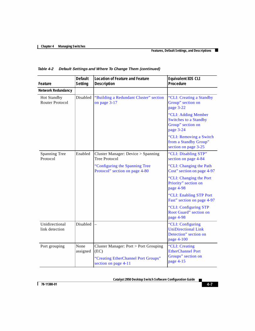
Network Redundancy
Hot StandbyRouter Protocol
Disabled “Building a Redundant Cluster” sectionon page 3-17
“CLI: Creating a StandbyGroup” section onpage 3-22
“CLI: Adding MemberSwitches to a StandbyGroup” section onpage 3-24
“CLI: Removing a Switchfrom a Standby Group”section on page 3-25
Spanning TreeProtocol
Enabled Cluster Manager: Device > SpanningTree Protocol
“Configuring the Spanning TreeProtocol” section on page 4-80
“CLI: Disabling STP”section on page 4-84
“CLI: Changing the PathCost” section on page 4-97
“CLI: Changing the PortPriority” section onpage 4-98
“CLI: Enabling STP PortFast” section on page 4-97
“CLI: Configuring STPRoot Guard” section onpage 4-98
Unidirectionallink detection
Disabled – “CLI: ConfiguringUniDirectional LinkDetection” section onpage 4-100
Port grouping Noneassigned
Cluster Manager: Port > Port Grouping(EC)
“Creating EtherChannel Port Groups”section on page 4-11
“CLI: CreatingEtherChannel PortGroups” section onpage 4-15
Table 4-2 Default Settings and Where To Change Them (continued)
FeatureDefaultSetting
Location of Feature and FeatureDescription
Equivalent IOS CLIProcedure
Chapter 4 Managing SwitchesFeatures, Default Settings, and Descriptions
4-8Catalyst 2950 Desktop Switch Software Configuration Guide
78-11380-01
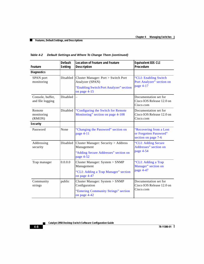
Diagnostics
SPAN portmonitoring
Disabled Cluster Manager: Port > Switch PortAnalyzer (SPAN)
“Enabling Switch Port Analyzer” sectionon page 4-15
“CLI: Enabling SwitchPort Analyzer” section onpage 4-17
Console, buffer,and file logging
Disabled – Documentation set forCisco IOS Release 12.0 onCisco.com
Remotemonitoring(RMON)
Disabled “Configuring the Switch for RemoteMonitoring” section on page 4-108
Documentation set forCisco IOS Release 12.0 onCisco.com
Security
Password None “Changing the Password” section onpage 4-11
“Recovering from a Lostor Forgotten Password”section on page 7-6
Addressingsecurity
Disabled Cluster Manager: Security > AddressManagement
“Adding Secure Addresses” section onpage 4-52
“CLI: Adding SecureAddresses” section onpage 4-54
Trap manager 0.0.0.0 Cluster Manager: System > SNMPManagement
“CLI: Adding a Trap Manager” sectionon page 4-47
“CLI: Adding a TrapManager” section onpage 4-47
Communitystrings
public Cluster Manager: System > SNMPConfiguration
“Entering Community Strings” sectionon page 4-42
Documentation set forCisco IOS Release 12.0 onCisco.com
Table 4-2 Default Settings and Where To Change Them (continued)
FeatureDefaultSetting
Location of Feature and FeatureDescription
Equivalent IOS CLIProcedure
4-9Catalyst 2950 Desktop Switch Software Configuration Guide
78-11380-01
Chapter 4 Managing SwitchesConfiguring Standalone Switches
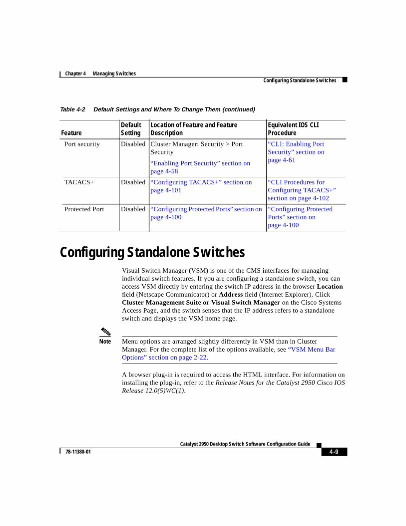
Configuring Standalone SwitchesVisual Switch Manager (VSM) is one of the CMS interfaces for managingindividual switch features. If you are configuring a standalone switch, you canaccess VSM directly by entering the switch IP address in the browserLocationfield (Netscape Communicator) orAddress field (Internet Explorer). ClickCluster Management Suite or Visual Switch Manager on the Cisco SystemsAccess Page, and the switch senses that the IP address refers to a standaloneswitch and displays the VSM home page.
Note Menu options are arranged slightly differently in VSM than in ClusterManager. For the complete list of the options available, see“VSM Menu BarOptions” section on page 2-22.
A browser plug-in is required to access the HTML interface. For information oninstalling the plug-in, refer to theRelease Notes for the Catalyst 2950 Cisco IOSRelease 12.0(5)WC(1).
Port security Disabled Cluster Manager: Security > PortSecurity
“Enabling Port Security” section onpage 4-58
“CLI: Enabling PortSecurity” section onpage 4-61
TACACS+ Disabled “Configuring TACACS+” section onpage 4-101
“CLI Procedures forConfiguring TACACS+”section on page 4-102
Protected Port Disabled“Configuring Protected Ports” section onpage 4-100
“Configuring ProtectedPorts” section onpage 4-100
Table 4-2 Default Settings and Where To Change Them (continued)
FeatureDefaultSetting
Location of Feature and FeatureDescription
Equivalent IOS CLIProcedure
Chapter 4 Managing SwitchesEnabling the Switch as a Command Switch
4-10Catalyst 2950 Desktop Switch Software Configuration Guide
78-11380-01
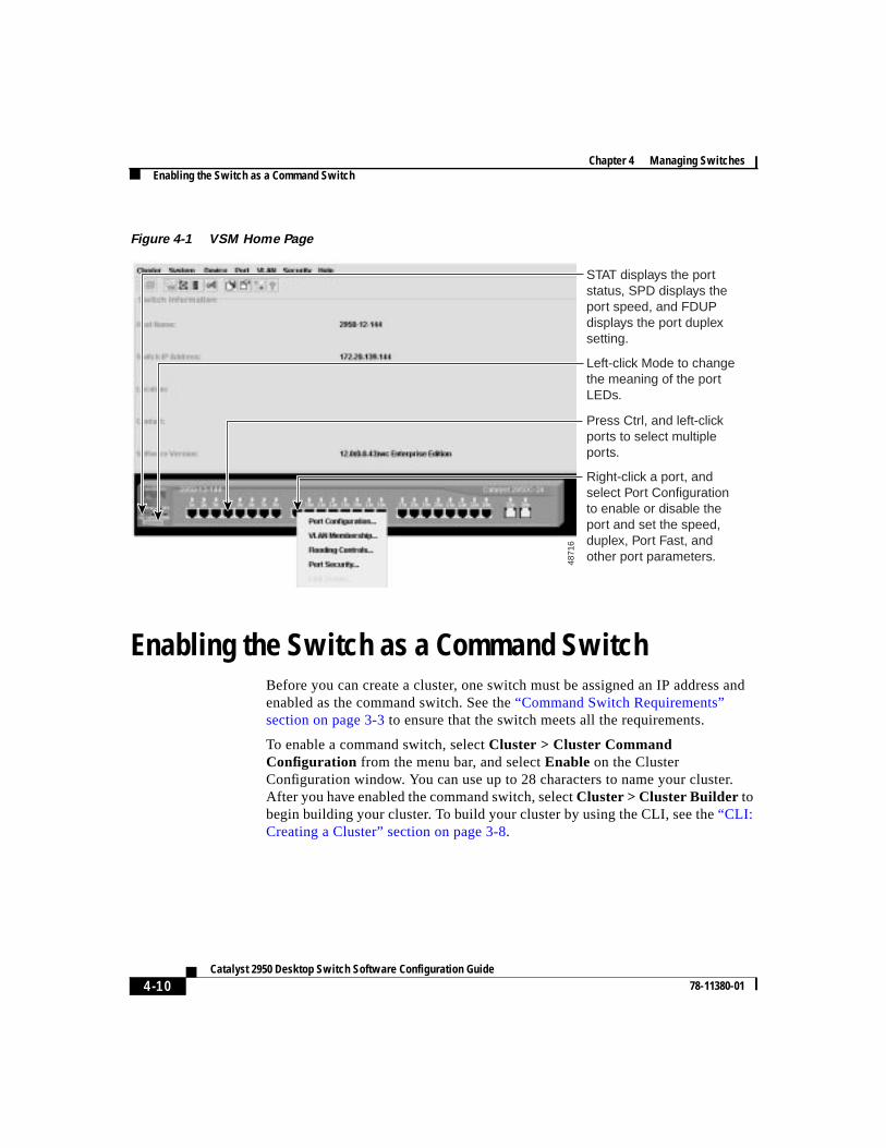
Figure 4-1 VSM Home Page
Enabling the Switch as a Command SwitchBefore you can create a cluster, one switch must be assigned an IP address andenabled as the command switch. See the“Command Switch Requirements”section on page 3-3 to ensure that the switch meets all the requirements.
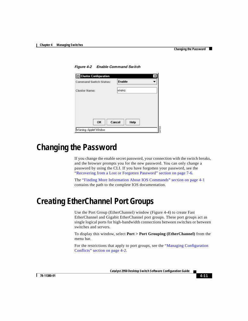
To enable a command switch, selectCluster > Cluster CommandConfiguration from the menu bar, and selectEnable on the ClusterConfiguration window. You can use up to 28 characters to name your cluster.After you have enabled the command switch, selectCluster > Cluster Builder tobegin building your cluster. To build your cluster by using the CLI, see the“CLI:Creating a Cluster” section on page 3-8.
4871
6
Right-click a port, and select Port Configuration to enable or disable the port and set the speed, duplex, Port Fast, and other port parameters.
STAT displays the port status, SPD displays the port speed, and FDUP displays the port duplex setting.
Left-click Mode to change the meaning of the port LEDs.
Press Ctrl, and left-click ports to select multiple ports.
4-11Catalyst 2950 Desktop Switch Software Configuration Guide
78-11380-01
Chapter 4 Managing SwitchesChanging the Password
Figure 4-2 Enable Command Switch
Changing the PasswordIf you change the enable secret password, your connection with the switch breaks,and the browser prompts you for the new password. You can only change apassword by using the CLI. If you have forgotten your password, see the“Recovering from a Lost or Forgotten Password” section on page 7-6.
The“Finding More Information About IOS Commands” section on page 4-1contains the path to the complete IOS documentation.
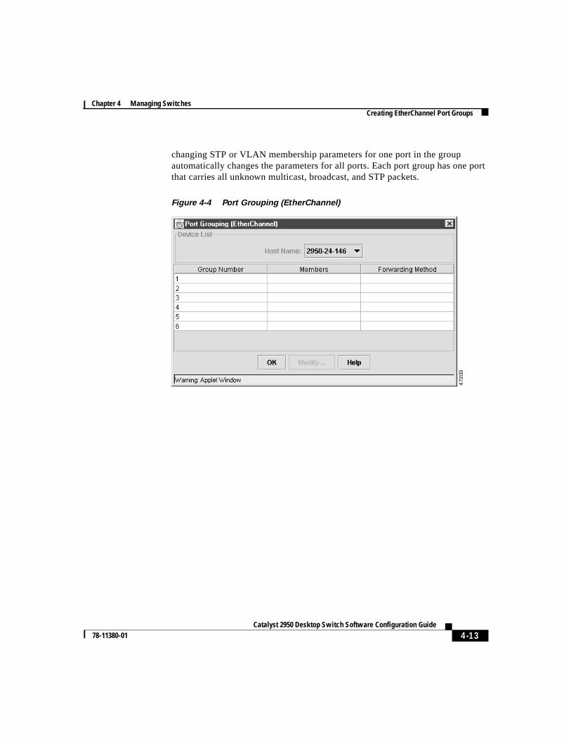
Creating EtherChannel Port GroupsUse the Port Group (EtherChannel) window (Figure 4-4) to create FastEtherChannel and Gigabit EtherChannel port groups. These port groups act assingle logical ports for high-bandwidth connections between switches or betweenswitches and servers.
To display this window, selectPort > Port Grouping (EtherChannel) from themenu bar.
For the restrictions that apply to port groups, see the“Managing ConfigurationConflicts” section on page 4-2.
3475
3
Chapter 4 Managing SwitchesCreating EtherChannel Port Groups
4-12Catalyst 2950 Desktop Switch Software Configuration Guide
78-11380-01
Understanding EtherChannel Port GroupingThis software release supports two different types of port groups: source-basedforwarding port groups and destination-based forwarding port groups.
Source-based forwarding port groups distribute packets forwarded to the groupbased on the source address of incoming packets. You can configure up to eightports in a source-based forwarding port group. Source-based forwarding isenabled by default.
Destination-based port groups distribute packets forwarded to the group based onthe destination address of incoming packets. You can configure up to eight portsin a group.
You can create up to 6 port groups of all source-based, all destination-based, or acombination of source- and destination-based ports. All ports in the group mustbe of the same type; for example, they must be all source based or all destinationbased. You can independently configure port groups that link switches, but youmust consistently configure both ends of a port group.
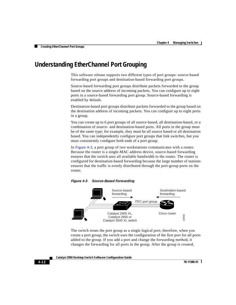
In Figure 4-3, a port group of two workstations communicates with a router.Because the router is a single-MAC address device, source-based forwardingensures that the switch uses all available bandwidth to the router. The router isconfigured for destination-based forwarding because the large number of stationsensures that the traffic is evenly distributed through the port-group ports on therouter.
Figure 4-3 Source-Based Forwarding
The switch treats the port group as a single logical port; therefore, when youcreate a port group, the switch uses the configuration of the first port for all portsadded to the group. If you add a port and change the forwarding method, itchanges the forwarding for all ports in the group. After the group is created,
FEC port group
4495
8
Source-basedforwarding
Destination-basedforwarding
Cisco routerCatalyst 2900 XL,Catalyst 2950 or
Catalyst 3500 XL switch
4-13Catalyst 2950 Desktop Switch Software Configuration Guide
78-11380-01
Chapter 4 Managing SwitchesCreating EtherChannel Port Groups
changing STP or VLAN membership parameters for one port in the groupautomatically changes the parameters for all ports. Each port group has one portthat carries all unknown multicast, broadcast, and STP packets.
Figure 4-4 Port Grouping (EtherChannel)
Chapter 4 Managing SwitchesCreating EtherChannel Port Groups
4-14Catalyst 2950 Desktop Switch Software Configuration Guide
78-11380-01
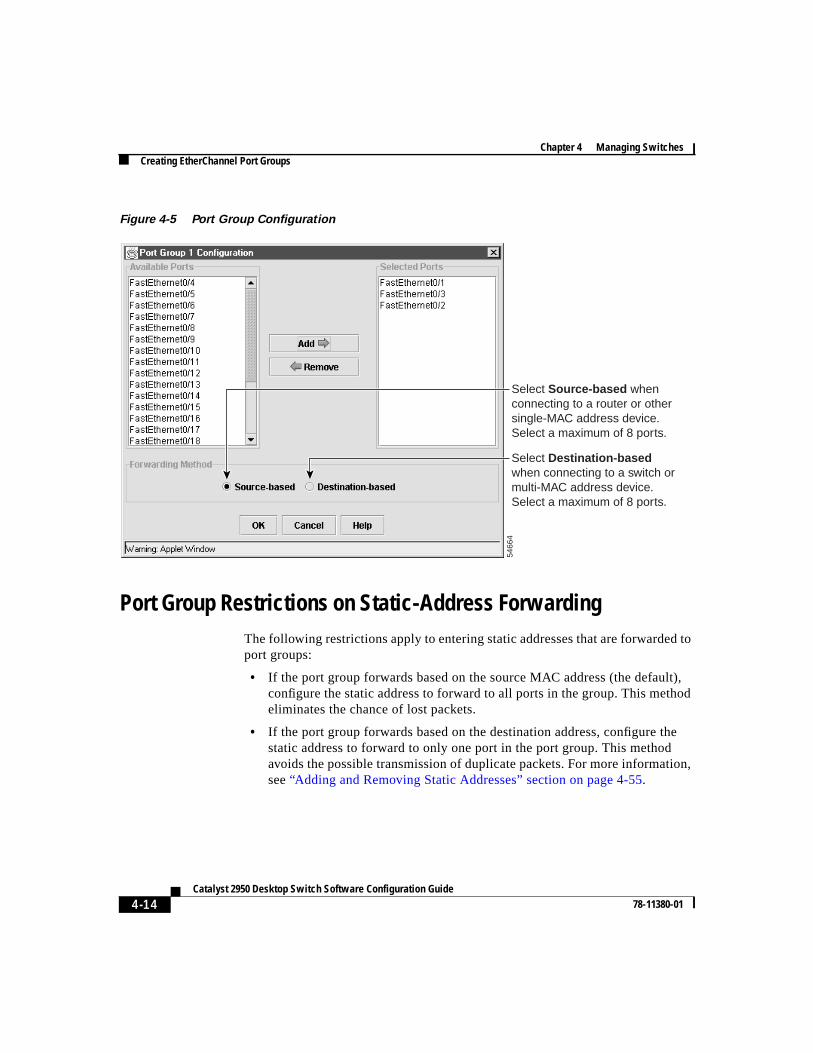
Figure 4-5 Port Group Configuration
Port Group Restrictions on Static-Address ForwardingThe following restrictions apply to entering static addresses that are forwarded toport groups:
• If the port group forwards based on the source MAC address (the default),configure the static address to forward to all ports in the group. This methodeliminates the chance of lost packets.
• If the port group forwards based on the destination address, configure thestatic address to forward to only one port in the port group. This methodavoids the possible transmission of duplicate packets. For more information,see“Adding and Removing Static Addresses” section on page 4-55.
Select Destination-based when connecting to a switch or multi-MAC address device. Select a maximum of 8 ports.
Select Source-based when connecting to a router or other single-MAC address device. Select a maximum of 8 ports.
5466
4
4-15Catalyst 2950 Desktop Switch Software Configuration Guide
78-11380-01
Chapter 4 Managing SwitchesEnabling Switch Port Analyzer
CLI: Creating EtherChannel Port GroupsBeginning in privileged EXEC mode, follow these steps to create a two-portgroup:
The“Finding More Information About IOS Commands” section on page 4-1contains the path to the complete IOS documentation.
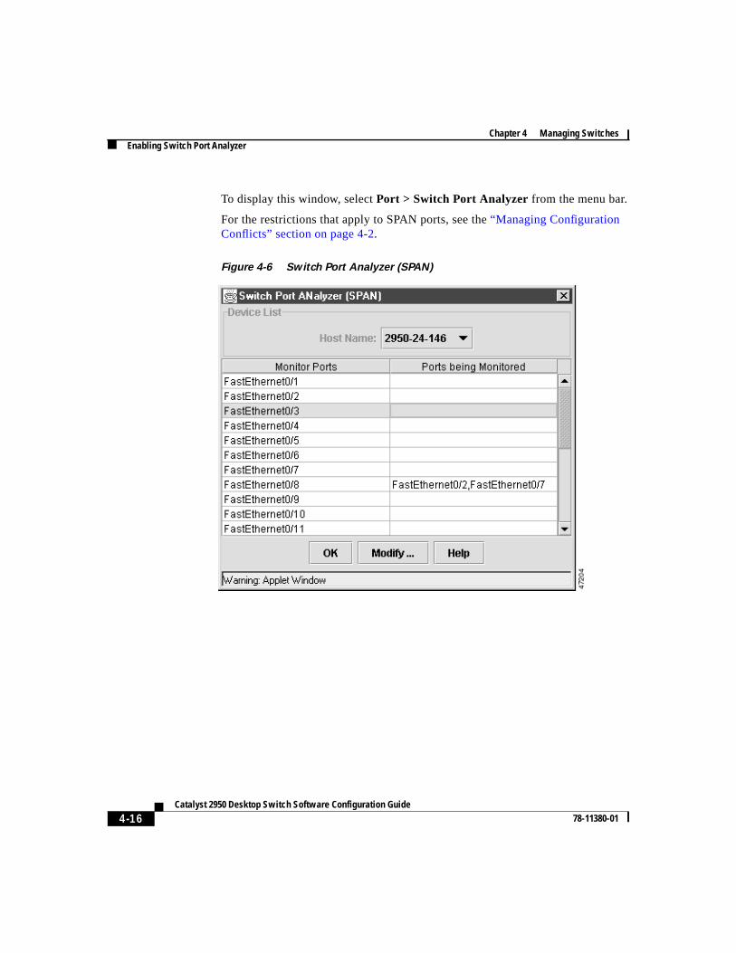
Enabling Switch Port AnalyzerYou can monitor traffic on a given port by forwarding incoming and outgoingtraffic on the port to another port in the same VLAN. Use the Switch PortAnalyzer (SPAN) window (Figure 4-6) to enable port monitoring on a port, anduse the Modify the Ports Being Monitored window (Figure 4-7) to select the portto be monitored. A SPAN port cannot monitor ports in a different VLAN, and aSPAN port must be a static-access port. You can have only one assigned monitorport at any given time. If you select another port as the monitor port, the previousmonitor port is disabled, and the newly selected port becomes the monitor port.
Command Purpose
Step 1 configure terminal Enter global configuration mode.
Step 2 interface interface Enter interface configuration mode, andenter the port of the first port to be added tothe group.
Step 3 port group 1 distributiondestination
Assign the port to group 1 withdestination-based forwarding.
Step 4 interface interface Enter the second port to be added to thegroup.
Step 5 port group 1 distributiondestination
Assign the port to group 1 withdestination-based forwarding.
Step 6 end Return to privileged EXEC mode.
Step 7 show running-config Verify your entries.
Chapter 4 Managing SwitchesEnabling Switch Port Analyzer
4-16Catalyst 2950 Desktop Switch Software Configuration Guide
78-11380-01
To display this window, selectPort > Switch Port Analyzer from the menu bar.
For the restrictions that apply to SPAN ports, see the“Managing ConfigurationConflicts” section on page 4-2.
Figure 4-6 Switch Port Analyzer (SPAN)
4-17Catalyst 2950 Desktop Switch Software Configuration Guide
78-11380-01
Chapter 4 Managing SwitchesEnabling Switch Port Analyzer
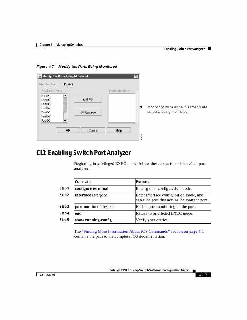
Figure 4-7 Modify the Ports Being Monitored
CLI: Enabling Switch Port AnalyzerBeginning in privileged EXEC mode, follow these steps to enable switch portanalyzer:
The“Finding More Information About IOS Commands” section on page 4-1contains the path to the complete IOS documentation.
2968
6
Monitor ports must be in same VLAN as ports being monitored.
Command Purpose
Step 1 configure terminal Enter global configuration mode.
Step 2 interface interface Enter interface configuration mode, andenter the port that acts as the monitor port.
Step 3 port monitor interface Enable port monitoring on the port.
Step 4 end Return to privileged EXEC mode.
Step 5 show running-config Verify your entries.
Chapter 4 Managing SwitchesConfiguring Flooding Controls
4-18Catalyst 2950 Desktop Switch Software Configuration Guide
78-11380-01
CLI: Disabling Switch Port AnalyzerBeginning in privileged EXEC mode, follow these steps to disable switch portanalyzer:
The“Finding More Information About IOS Commands” section on page 4-1contains the path to the complete IOS documentation.
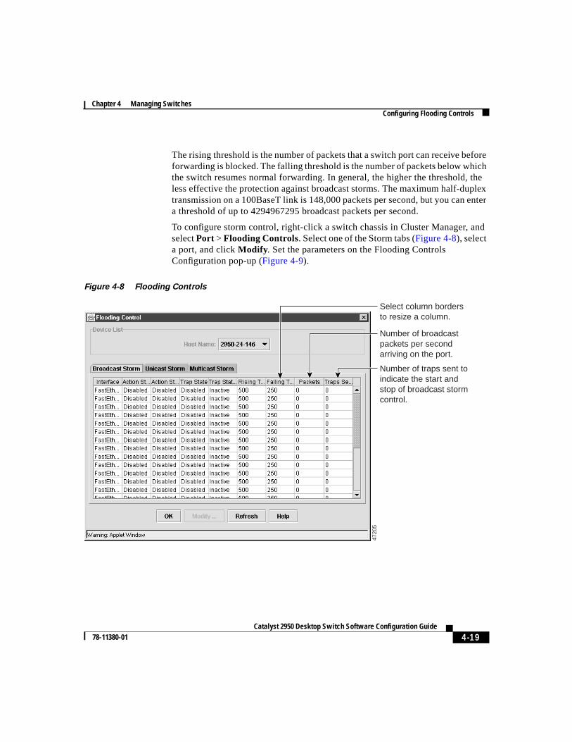
Configuring Flooding ControlsUse the Flooding Controls window (Figure 4-8) to block the forwarding ofunnecessary flooded traffic.
To display this window, selectPort > Flooding Controls from the menu bar.
Enabling Storm ControlA packet storm occurs when a large number of broadcast, unicast, or multicastpackets are received on a port. Forwarding these packets can cause the network toslow down or to time out. Storm control is configured for the switch as a wholebut operates on a per-port basis. By default, storm control is disabled.
Storm control uses high and low thresholds to block and then restore theforwarding of broadcast, unicast, or multicast packets. You can also set the switchto shut down the port when the rising threshold is reached.
Command Purpose
Step 1 configure terminal Enter global configuration mode.
Step 2 interface interface Enter interface configuration mode, andenter the port number of the monitor port.
Step 3 no port monitor interface Disable port monitoring on the port.
Step 4 end Return to privileged EXEC mode.
Step 5 show running-config Verify your entries.
4-19Catalyst 2950 Desktop Switch Software Configuration Guide
78-11380-01
Chapter 4 Managing SwitchesConfiguring Flooding Controls
The rising threshold is the number of packets that a switch port can receive beforeforwarding is blocked. The falling threshold is the number of packets below whichthe switch resumes normal forwarding. In general, the higher the threshold, theless effective the protection against broadcast storms. The maximum half-duplextransmission on a 100BaseT link is 148,000 packets per second, but you can entera threshold of up to 4294967295 broadcast packets per second.
To configure storm control, right-click a switch chassis in Cluster Manager, andselectPort > Flooding Controls. Select one of the Storm tabs (Figure 4-8), selecta port, and clickModify . Set the parameters on the Flooding ControlsConfiguration pop-up (Figure 4-9).
Figure 4-8 Flooding Controls
Number of broadcast packets per second arriving on the port.
Number of traps sent to indicate the start and stop of broadcast storm control.
4720
5
Select column borders to resize a column.
Chapter 4 Managing SwitchesConfiguring Flooding Controls
4-20Catalyst 2950 Desktop Switch Software Configuration Guide
78-11380-01
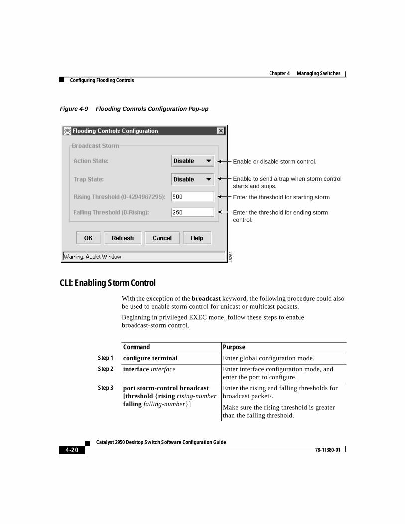
Figure 4-9 Flooding Controls Configuration Pop-up
CLI: Enabling Storm Control
With the exception of thebroadcastkeyword, the following procedure could alsobe used to enable storm control for unicast or multicast packets.
Beginning in privileged EXEC mode, follow these steps to enablebroadcast-storm control.
4526
2
Enable or disable storm control.
Enable to send a trap when storm control starts and stops.
Enter the threshold for starting storm
Enter the threshold for ending storm control.
Command Purpose
Step 1 configure terminal Enter global configuration mode.
Step 2 interface interface Enter interface configuration mode, andenter the port to configure.
Step 3 port storm-control broadcast[threshold { rising rising-numberfalling falling-number}]
Enter the rising and falling thresholds forbroadcast packets.
Make sure the rising threshold is greaterthan the falling threshold.
4-21Catalyst 2950 Desktop Switch Software Configuration Guide
78-11380-01
Chapter 4 Managing SwitchesConfiguring Flooding Controls
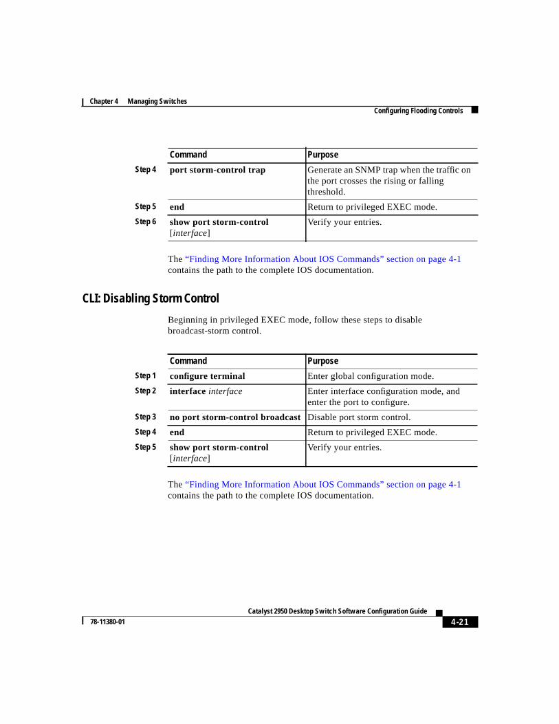
The“Finding More Information About IOS Commands” section on page 4-1contains the path to the complete IOS documentation.
CLI: Disabling Storm Control
Beginning in privileged EXEC mode, follow these steps to disablebroadcast-storm control.
The“Finding More Information About IOS Commands” section on page 4-1contains the path to the complete IOS documentation.
Step 4 port storm-control trap Generate an SNMP trap when the traffic onthe port crosses the rising or fallingthreshold.
Step 5 end Return to privileged EXEC mode.
Step 6 show port storm-control[ interface]
Verify your entries.
Command Purpose
Command Purpose
Step 1 configure terminal Enter global configuration mode.
Step 2 interface interface Enter interface configuration mode, andenter the port to configure.
Step 3 no port storm-control broadcast Disable port storm control.
Step 4 end Return to privileged EXEC mode.
Step 5 show port storm-control[ interface]
Verify your entries.

Chapter 4 Managing SwitchesManaging the System Date and Time
4-22Catalyst 2950 Desktop Switch Software Configuration Guide
78-11380-01
Managing the System Date and TimeUse the System Time Management window (Figure 4-10) to set the system timefor a switch or enable an external source such as Network Time Protocol (NTP)to supply time to the switch.
You can use this window to set the switch time by using one of the followingtechniques:
• Manually setting the system time (including daylight saving time) and date
• Configuring the switch to run in NTP client mode and to receive timeinformation from an NTP server
• Configuring the switch to run in NTP broadcast-client mode and to receiveinformation from an NTP broadcast server
To display this window, selectCluster > System Time Managementfrom themenu bar.
Setting the System Date and TimeEnter the date and a 24-hour clock time setting on the System Time Managementwindow. If you are entering the time for an American time zone, enter thethree-letter abbreviation for the time zone in theName of Time Zonefield, suchas PST for Pacific standard time. If you are identifying the time zone by referringto Greenwich mean time, enter UTC (universal coordinated time) in theName ofTime Zone field. You then must enter a negative or positive number as an offsetto indicate the number of time zones between the switch and Greenwich, England.Enter a negative number if the switch is west of Greenwich, England, and east ofthe international date line. For example, California is eight time zones west ofGreenwich, so you would enter –8 in theHours Offset From UTC field. Enter apositive number if the switch is east of Greenwich. You can also enter negativeand positive numbers for minutes.
You can also set the date and time by using the CLI.“Finding More InformationAbout IOS Commands” section on page 4-1contains the path to the complete IOSdocumentation.
4-23Catalyst 2950 Desktop Switch Software Configuration Guide
78-11380-01
Chapter 4 Managing SwitchesManaging the System Date and Time
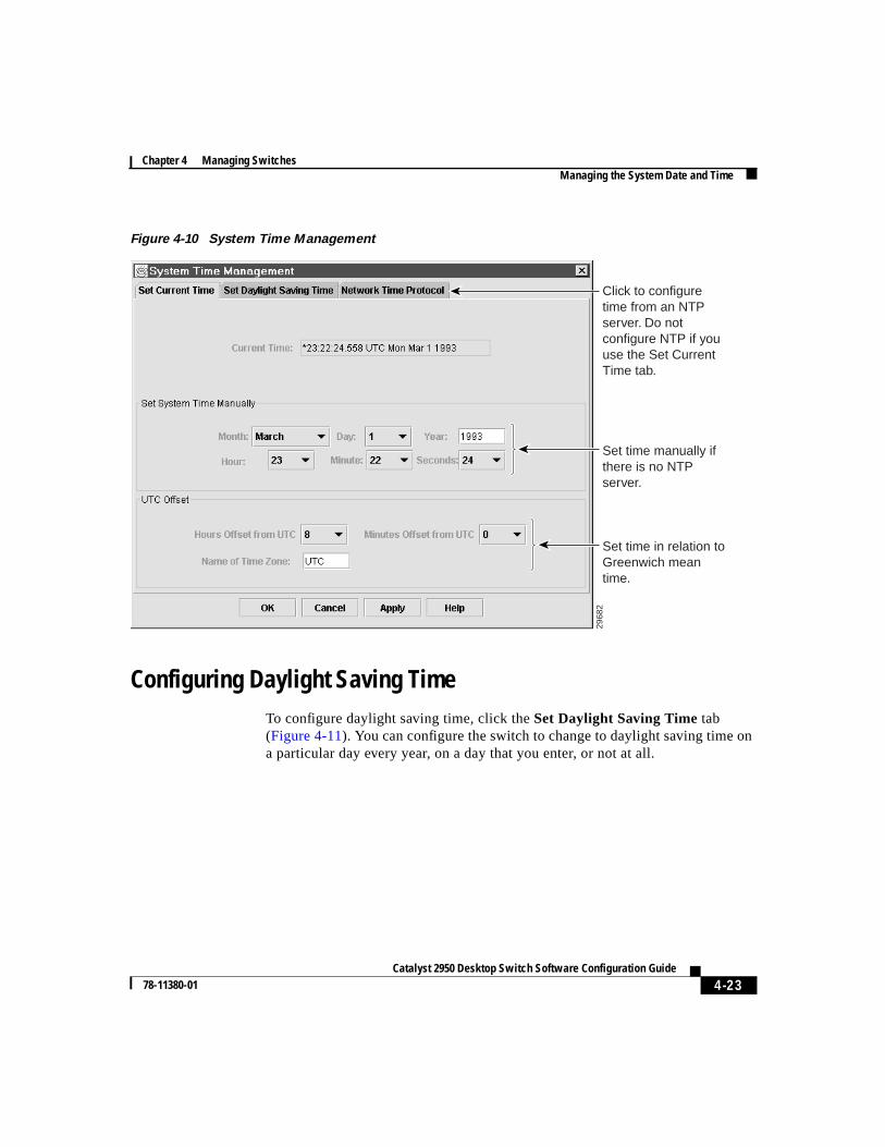
Figure 4-10 System Time Management
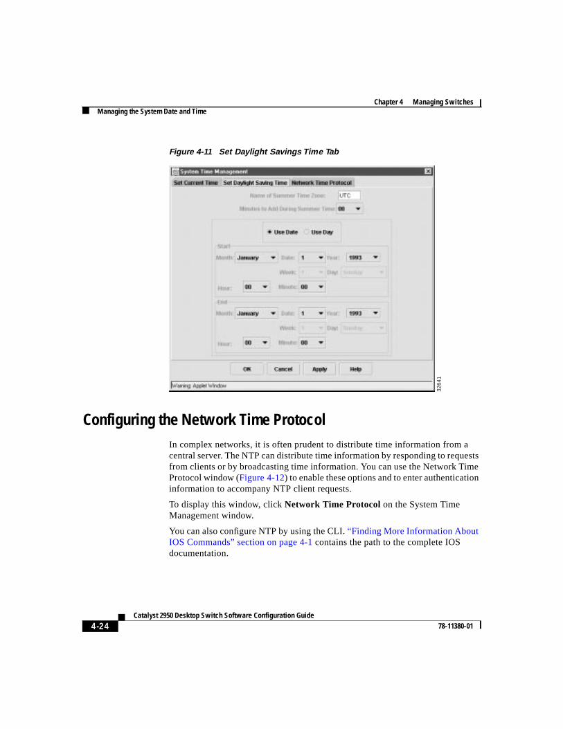
Configuring Daylight Saving TimeTo configure daylight saving time, click theSet Daylight Saving Time tab(Figure 4-11). You can configure the switch to change to daylight saving time ona particular day every year, on a day that you enter, or not at all.
2968
2
Click to configure time from an NTP server. Do not configure NTP if you use the Set Current Time tab.
Set time manually if there is no NTP server.
Set time in relation to Greenwich mean time.
Chapter 4 Managing SwitchesManaging the System Date and Time
4-24Catalyst 2950 Desktop Switch Software Configuration Guide
78-11380-01
Figure 4-11 Set Daylight Savings Time Tab
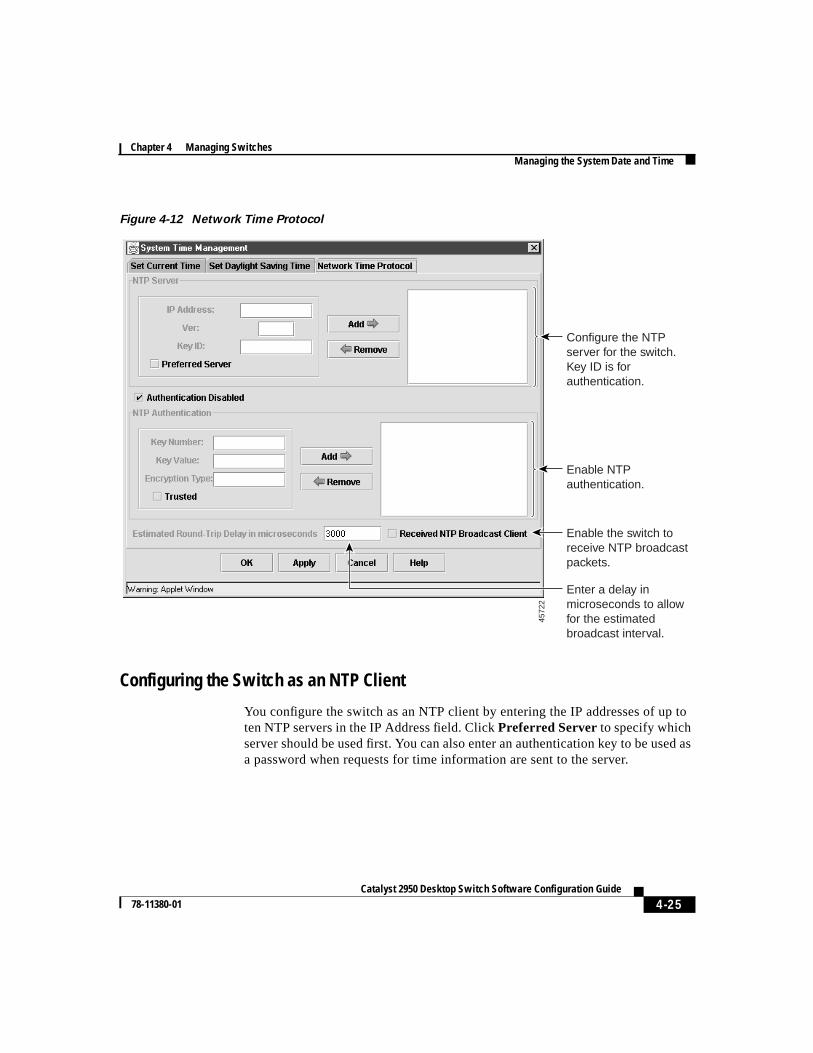
Configuring the Network Time ProtocolIn complex networks, it is often prudent to distribute time information from acentral server. The NTP can distribute time information by responding to requestsfrom clients or by broadcasting time information. You can use the Network TimeProtocol window (Figure 4-12) to enable these options and to enter authenticationinformation to accompany NTP client requests.
To display this window, clickNetwork Time Protocol on the System TimeManagement window.
You can also configure NTP by using the CLI.“Finding More Information AboutIOS Commands” section on page 4-1 contains the path to the complete IOSdocumentation.
3264
1
4-25Catalyst 2950 Desktop Switch Software Configuration Guide
78-11380-01
Chapter 4 Managing SwitchesManaging the System Date and Time
Figure 4-12 Network Time Protocol
Configuring the Switch as an NTP Client
You configure the switch as an NTP client by entering the IP addresses of up toten NTP servers in the IP Address field. ClickPreferred Server to specify whichserver should be used first. You can also enter an authentication key to be used asa password when requests for time information are sent to the server.
4572
2
Configure the NTP server for the switch. Key ID is for authentication.
Enable NTP authentication.
Enable the switch to receive NTP broadcast packets.
Enter a delay in microseconds to allow for the estimated broadcast interval.
Chapter 4 Managing SwitchesConfiguring IP Information
4-26Catalyst 2950 Desktop Switch Software Configuration Guide
78-11380-01
Enabling NTP Authentication
To ensure the validity of information received from NTP servers, you canauthenticate NTP messages with public-key encryption. This procedure must becoordinated with the administrator of the NTP servers: the information you enteron this window will be matched by the servers to authenticate it.
Click Help for more information about entering information in the Key Number,Key Value, and Encryption Type fields.
Configuring the Switch for NTP Broadcast-Client Mode
You can configure the switch to receive NTP broadcast messages if there is anNTP broadcast server, such as a router, broadcasting time information on thenetwork. You can also enter a delay in the Estimated Round-Trip Delay field toaccount for round-trip delay between the client and the NTP broadcast server.
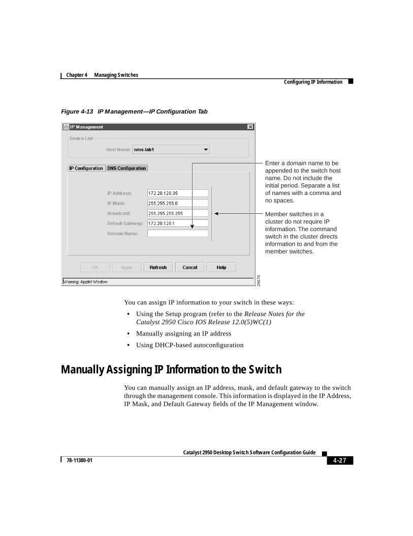
Configuring IP InformationUse the IP Management window (Figure 4-13) to change or enter IP informationfor the switch. Some of this information, such as the IP address was previouslyentered.
You can use this window to perform the following tasks:
• Assign IP information.
• Remove an IP address.
• Specify a domain name, and configure the Domain Name System (DNS)server.
To display this window, selectSystem > IP Managementfrom the menu bar.
4-27Catalyst 2950 Desktop Switch Software Configuration Guide
78-11380-01
Chapter 4 Managing SwitchesConfiguring IP Information
Figure 4-13 IP Management—IP Configuration Tab
You can assign IP information to your switch in these ways:
• Using the Setup program (refer to theRelease Notes for theCatalyst 2950 Cisco IOS Release 12.0(5)WC(1)
• Manually assigning an IP address
• Using DHCP-based autoconfiguration
Manually Assigning IP Information to the SwitchYou can manually assign an IP address, mask, and default gateway to the switchthrough the management console. This information is displayed in the IP Address,IP Mask, and Default Gateway fields of the IP Management window.
2967
9
Member switches in a cluster do not require IP information. The command switch in the cluster directs information to and from the member switches.
Enter a domain name to be appended to the switch host name. Do not include the initial period. Separate a list of names with a comma and no spaces.
Chapter 4 Managing SwitchesConfiguring IP Information
4-28Catalyst 2950 Desktop Switch Software Configuration Guide
78-11380-01
You can change the information in these fields. The mask identifies the bits thatdenote the network number in the IP address. When you use the mask to subnet anetwork, the mask is then referred to as a subnet mask. The broadcast address isreserved for sending messages to all hosts. The CPU sends traffic to an unknownIP address through the default gateway.
Caution Changing the command switch IP address on this window ends your VSMsession and any SNMP or Telnet sessions in progress. Restart the ClusterManager by entering the new IP address in the browserLocation field(Netscape Communicator) orAddress field (Internet Explorer), as describedin the“Using VSM” section on page 2-20.
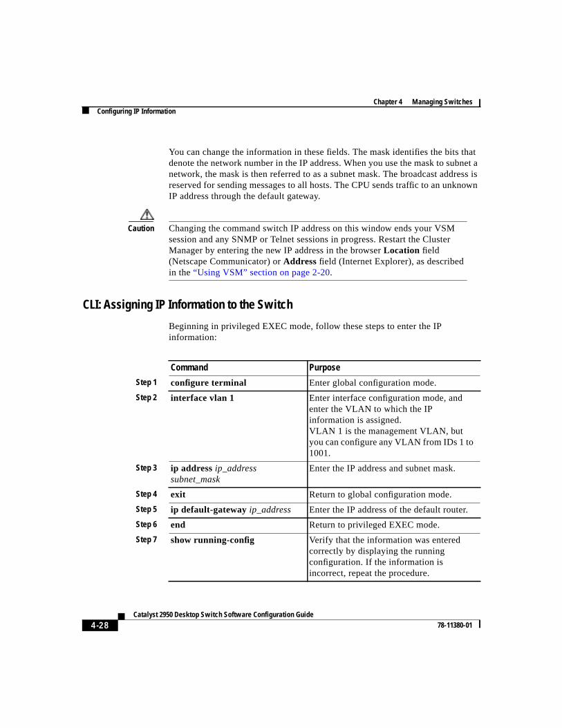
CLI: Assigning IP Information to the Switch
Beginning in privileged EXEC mode, follow these steps to enter the IPinformation:
Command Purpose
Step 1 configure terminal Enter global configuration mode.
Step 2 interface vlan 1 Enter interface configuration mode, andenter the VLAN to which the IPinformation is assigned.VLAN 1 is the management VLAN, butyou can configure any VLAN from IDs 1 to1001.
Step 3 ip addressip_addresssubnet_mask
Enter the IP address and subnet mask.
Step 4 exit Return to global configuration mode.
Step 5 ip default-gateway ip_address Enter the IP address of the default router.
Step 6 end Return to privileged EXEC mode.
Step 7 show running-config Verify that the information was enteredcorrectly by displaying the runningconfiguration. If the information isincorrect, repeat the procedure.
4-29Catalyst 2950 Desktop Switch Software Configuration Guide
78-11380-01
Chapter 4 Managing SwitchesConfiguring IP Information
The“Finding More Information About IOS Commands” section on page 4-1contains the path to the complete IOS documentation.
CLI: Removing an IP Address
Use the following procedure to remove the IP information from a switch.
Note Using theno ip address command in configuration mode disables the IPprotocol stack as well as removes the IP information. Cluster members withoutIP addresses rely on the IP protocol stack being enabled.
Beginning in privileged EXEC mode, follow these steps to remove an IP address:
Caution If you are removing the IP address through a Telnet session, your connectionto the switch will be lost.
The“Finding More Information About IOS Commands” section on page 4-1contains the path to the complete IOS documentation.
DHCP-Based AutoconfigurationThe DHCP provides configuration information to Internet hosts andinternetworking devices. This protocol consists of two components: one fordelivering configuration parameters from a DHCP server to a device and a
Command Purpose
Step 1 clear ip address vlan 1ip_address subnet_mask
Remove the IP address and subnet mask.
Step 2 end Return to privileged EXEC mode.
Step 3 show running-config Verify that the information was removed bydisplaying the running configuration.
Chapter 4 Managing SwitchesConfiguring IP Information
4-30Catalyst 2950 Desktop Switch Software Configuration Guide
78-11380-01
mechanism for allocating network addresses to devices. DHCP is built on aclient-server model, where designated DHCP servers allocate network addressesand deliver configuration parameters to dynamically configured devices.
With DHCP-based autoconfiguration, your switch (DHCP client) can beautomatically configured at startup with IP address information and aconfiguration file that it receives during DHCP-based autoconfiguration.
With DHCP-based autoconfiguration, no DHCP client-side configuration isrequired on your switch. However, you need to configure the DHCP server forvarious lease options. You might also need to configure a TFTP server, a DomainName System (DNS) server, and possibly a relay device if the servers are on adifferent LAN than your switch. A relay device forwards broadcast trafficbetween two directly connected LANs. A router does not forward broadcastpackets, but it forwards packets based on the destination IP address in the receivedpacket. DHCP-based autoconfiguration replaces the BOOTP client functionalityon your switch.
DHCP Client Request Process
When you boot your switch, the DHCP client can be invoked and automaticallyrequest configuration information from a DHCP server under the followingconditions:
• The configuration file is not present on the switch.
• The configuration file is present, but the IP address is not specified in it.
• The configuration file is present, the IP address is not specified in it, and theservice config global configuration command is included. This commandenables the autoloading of a configuration file from a network server.
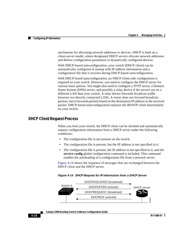
Figure 4-14 shows the sequence of messages that are exchanged between theDHCP client and the DHCP server.
Figure 4-14 DHCP Request for IP Information from a DHCP Server
Switch A
DHCPACK (unicast)
DHCPREQUEST (broadcast)
DHCPOFFER (unicast)
DHCPDISCOVER (broadcast)
DHCP server
5183
4
4-31Catalyst 2950 Desktop Switch Software Configuration Guide
78-11380-01
Chapter 4 Managing SwitchesConfiguring IP Information
The client, Switch A, broadcasts a DHCPDISCOVER message to locate a DHCPserver. The DHCP server offers configuration parameters (such as an IP address,subnet mask, gateway IP address, DNS IP address, a lease for the IP address, andso forth) to the client in a DHCPOFFER unicast message.
In a DHCPREQUEST broadcast message, the client returns a formal request forthe offered configuration information to the DHCP server. The formal request isbroadcast so that all other DHCP servers that received the DHCPDISCOVERbroadcast message from the client can reclaim the IP addresses that they offeredto the client.
The DHCP server confirms that the IP address has been allocated to the client byreturning a DHCPACK unicast message to the client. With this message, the clientand server are bound, and the client uses configuration information received fromthe server. The amount of information the switch receives depends on how youconfigure the DHCP server. For more information, see the“Configuring theDHCP Server” section on page 4-32.
If the configuration parameters sent to the client in the DHCPOFFER unicastmessage by the DHCP server are invalid (a configuration error exists), the clientreturns a DHCPDECLINE broadcast message to the DHCP server.
The DHCP server sends the client a DHCPNAK denial broadcast message, whichmeans the offered configuration parameters have not been assigned, an error hasoccurred during the negotiation of the parameters, or the client has been slow inresponding to the DHCPOFFER message (the DHCP server assigned theparameters to another client) of the DHCP server.
A DHCP client might receive offers from multiple DHCP or BOOTP servers andcan accept any one of the offers; however, the client usually accepts the first offerit receives. The offer from the DHCP server is not a guarantee that the IP addresswill be allocated to the client; however, the server usually reserves the addressuntil the client has had a chance to formally request the address. If the switchaccepts replies from a BOOTP server and configures itself, the switch willbroadcast, instead of unicast, TFTP requests to obtain the switch configurationfile.
Chapter 4 Managing SwitchesConfiguring IP Information
4-32Catalyst 2950 Desktop Switch Software Configuration Guide
78-11380-01
Configuring the DHCP Server
You should configure the DHCP servers with reserved leases that are bound toeach switch by the switch hardware address. If the DHCP server does not supportreserved leases, the switch can obtain different IP addresses and configurationfiles at different boot instances. You should configure the DHCP server with thefollowing lease options:
• IP address of the client (required)
• Subnet mask of the client (required)
• DNS server IP address (required)
• Router IP address (default gateway address to be used by the switch)(required)
• TFTP server name (required)
• Boot filename (the name of the configuration file that the client needs)(recommended)
• Host name (optional)
If you do not configure the DHCP server with the lease options described earlier,then it replies to client requests with only those parameters that have availablevalues. If the IP address and subnet mask are not in the reply, the switch is notconfigured. If the DNS server IP address, router IP address, or TFTP server nameare not found, the switch might broadcast TFTP requests. Unavailability of otherlease options does not affect autoconfiguration.
Note If the configuration file on the switch does not contain the IP address, theswitch obtains its address, mask, gateway IP address, and host name fromDHCP. If theservice configglobal configuration command is specified in theconfiguration file, the switch receives the configuration file through TFTPrequests. If theservice config global configuration command and the IPaddress are both present in the configuration file, DHCP is not used, and theswitch obtains the default configuration file by broadcasting TFTP requests.
The DHCP server can be on the same or a different LAN as the switch. If it is ona different LAN, the switch must be able to access it through a relay device. TheDHCP server can be running on a UNIX or Linux operating system; however, theWindows NT operating system is not supported in this release.
4-33Catalyst 2950 Desktop Switch Software Configuration Guide
78-11380-01
Chapter 4 Managing SwitchesConfiguring IP Information
For more information, see the“Configuring the Relay Device” section onpage 4-34. You must also set up the TFTP server with the switch configurationfiles; for more information, see the next section.
Configuring the TFTP Server
The TFTP server must contain one or more configuration files in its basedirectory. The files can include the following:
• The configuration file named in the DHCP reply (the actual switchconfiguration file)
• The network-confg or the cisconet.cfg file (known as the defaultconfiguration files)
• The router-confg or the ciscortr.cfg file (These files contain commandscommon to all switches. Normally, if the DHCP and TFTP servers areproperly configured, these files are not accessed.)
You must specify the TFTP server name in the DHCP server lease database. Youmust also specify the TFTP server name-to-IP-address mapping in the DNS serverdatabase.
The TFTP server can be on the same or a different LAN as the switch. If it is ona different LAN, the switch must be able to access it through a relay device or arouter. For more information, see the“Configuring the Relay Device” section onpage 4-34.
If the configuration filename is provided in the DHCP server reply, theconfiguration files for multiple switches can be spread over multiple TFTPservers. However, if the configuration filename is not provided, then theconfiguration files must reside on a single TFTP server.
Configuring the DNS
The switch uses the DNS server to resolve the TFTP server name to a TFTP serverIP address. You must configure the TFTP server name-to-IP address map on theDNS server. The TFTP server contains the configuration files for the switch.
You must configure the IP addresses of the DNS servers in the lease database ofthe DHCP server from where the DHCP replies will retrieve them. You can enterup to two DNS server IP addresses in the lease database.
Chapter 4 Managing SwitchesConfiguring IP Information
4-34Catalyst 2950 Desktop Switch Software Configuration Guide
78-11380-01
The DNS server can be on the same or a different LAN as the switch. If it is on adifferent LAN, the switch must be able to access it through a relay device orrouter. For more information, see the“Configuring the Relay Device” section onpage 4-34.
Configuring the Relay Device
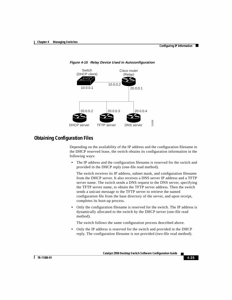
You need to use a relay device if the DHCP, DNS, or TFTP servers are on adifferent LAN than the switch. You must configure this relay device to forwardreceived broadcast packets on an interface to the destination host. Thisconfiguration ensures that broadcasts from the DHCP client can reach the DHCP,DNS, and TFTP servers and that broadcasts from the servers can reach the DHCPclient.
If the relay device is a Cisco router, you enable IP routing (ip routing globalconfiguration command) and configure it with helper addresses by using theiphelper-address interface configuration command.
For example, inFigure 4-15, you configure the router interfaces as follows:
On interface 10.0.0.2:
router(config-if)# ip helper-address 20.0.0.2router(config-if)# ip helper-address 20.0.0.3router(config-if)# ip helper-address 20.0.0.4
On interface 20.0.0.1
router(config-if)# ip helper-address 10.0.0.1
4-35Catalyst 2950 Desktop Switch Software Configuration Guide
78-11380-01
Chapter 4 Managing SwitchesConfiguring IP Information
Figure 4-15 Relay Device Used in Autoconfiguration
Obtaining Configuration Files
Depending on the availability of the IP address and the configuration filename inthe DHCP reserved lease, the switch obtains its configuration information in thefollowing ways:
• The IP address and the configuration filename is reserved for the switch andprovided in the DHCP reply (one-file read method).
The switch receives its IP address, subnet mask, and configuration filenamefrom the DHCP server. It also receives a DNS server IP address and a TFTPserver name. The switch sends a DNS request to the DNS server, specifyingthe TFTP server name, to obtain the TFTP server address. Then the switchsends a unicast message to the TFTP server to retrieve the namedconfiguration file from the base directory of the server, and upon receipt,completes its boot-up process.
• Only the configuration filename is reserved for the switch. The IP address isdynamically allocated to the switch by the DHCP server (one-file readmethod).
The switch follows the same configuration process described above.
• Only the IP address is reserved for the switch and provided in the DHCPreply. The configuration filename is not provided (two-file read method).
Switch(DHCP client)
Cisco router(Relay)
5183
6
DHCP server TFTP server DNS server
20.0.0.2 20.0.0.3
20.0.0.110.0.0.2
10.0.0.1
20.0.0.4
Chapter 4 Managing SwitchesConfiguring IP Information
4-36Catalyst 2950 Desktop Switch Software Configuration Guide
78-11380-01
The switch receives its IP address and subnet mask from the DHCP server. Italso receives a DNS server IP address and a TFTP server name. The switchsends a DNS request to the DNS server, specifying the TFTP server name, toobtain the TFTP server address.
The switch sends a unicast message to the TFTP server to retrieve thenetwork-confg or cisconet.cfg default configuration file. (If thenetwork-confg file cannot be read, the switch reads the cisconet.cfg file.)
The default configuration file contains the host names-to-IP-address mappingfor the switch. The switch fills its host table with the information in the fileand obtains its host name. If the host name is not found in the file, the switchuses the host name in the DHCP reply. If the host name is not specified in theDHCP reply, the switch uses the default “Switch” as its host name.
After obtaining its host name from the default configuration file or the DHCPreply, the switch reads the configuration file that has the same name as its hostname (hostname-confg orhostname.cfg, depending on whethernetwork-confg or cisconet.cfg was read earlier) from the TFTP server. If thecisconet.cfg file is read, the filename of the host is truncated to eightcharacters.
If the switch cannot read the network-confg, cisconet.cfg, or the host-namefile, it reads the router-confg file. If the switch cannot read the router-confgfile, it reads the ciscortr.cfg file.
Note The switch broadcasts TFTP server requests if the TFTP server name is notobtained from the DHCP replies, if all attempts to read the configuration filethrough unicast transmissions fail, or if the TFTP server name cannot beresolved to an IP address.
4-37Catalyst 2950 Desktop Switch Software Configuration Guide
78-11380-01
Chapter 4 Managing SwitchesConfiguring IP Information
Example Configuration
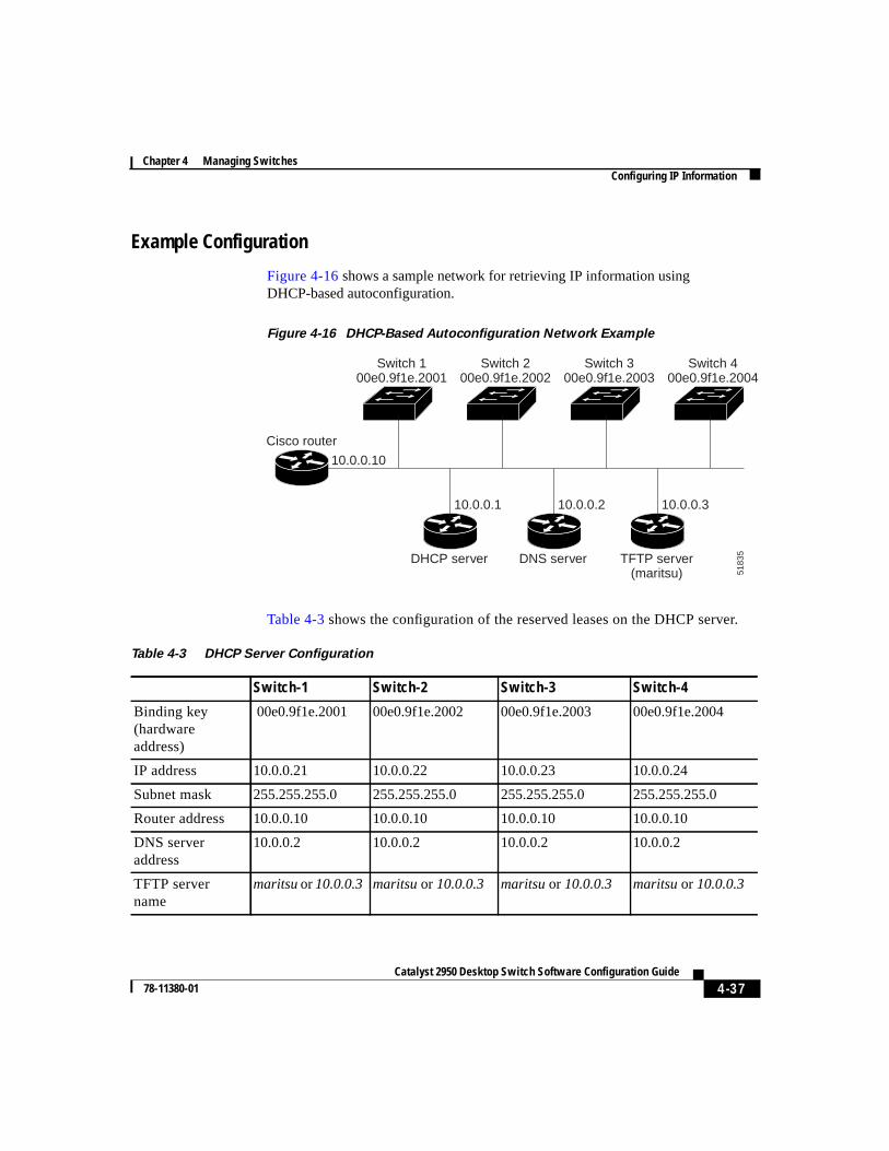
Figure 4-16shows a sample network for retrieving IP information usingDHCP-based autoconfiguration.
Figure 4-16 DHCP-Based Autoconfiguration Network Example
Table 4-3 shows the configuration of the reserved leases on the DHCP server.
Switch 100e0.9f1e.2001
Cisco router
5183
5
Switch 200e0.9f1e.2002
Switch 300e0.9f1e.2003
DHCP server DNS server TFTP server(maritsu)
10.0.0.1
10.0.0.10
10.0.0.2 10.0.0.3
Switch 400e0.9f1e.2004
Table 4-3 DHCP Server Configuration
Switch-1 Switch-2 Switch-3 Switch-4
Binding key(hardwareaddress)
00e0.9f1e.2001 00e0.9f1e.2002 00e0.9f1e.2003 00e0.9f1e.2004
IP address 10.0.0.21 10.0.0.22 10.0.0.23 10.0.0.24
Subnet mask 255.255.255.0 255.255.255.0 255.255.255.0 255.255.255.0
Router address 10.0.0.10 10.0.0.10 10.0.0.10 10.0.0.10
DNS serveraddress
10.0.0.2 10.0.0.2 10.0.0.2 10.0.0.2
TFTP servername
maritsuor10.0.0.3 maritsu or 10.0.0.3 maritsu or 10.0.0.3 maritsu or 10.0.0.3
Chapter 4 Managing SwitchesConfiguring IP Information
4-38Catalyst 2950 Desktop Switch Software Configuration Guide
78-11380-01
DNS Server Configuration
The DNS server maps the TFTP server namemaritsu to IP address 10.0.0.3.
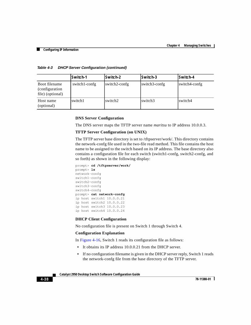
TFTP Server Configuration (on UNIX)
The TFTP server base directory is set to /tftpserver/work/. This directory containsthe network-confg file used in the two-file read method. This file contains the hostname to be assigned to the switch based on its IP address. The base directory alsocontains a configuration file for each switch (switch1-confg, switch2-confg, andso forth) as shown in the following display:
prompt> cd /tftpserver/work/prompt> lsnetwork-confgswitch1-confgswitch2-confgswitch3-confgswitch4-confgprompt> cat network-confgip host switch1 10.0.0.21ip host switch2 10.0.0.22ip host switch3 10.0.0.23ip host switch4 10.0.0.24
DHCP Client Configuration
No configuration file is present on Switch 1 through Switch 4.
Configuration Explanation
In Figure 4-16, Switch 1 reads its configuration file as follows:
• It obtains its IP address 10.0.0.21 from the DHCP server.
• If no configuration filename is given in the DHCP server reply, Switch 1 readsthe network-confg file from the base directory of the TFTP server.
Boot filename(configurationfile) (optional)
switch1-confg switch2-confg switch3-confg switch4-confg
Host name(optional)
switch1 switch2 switch3 switch4
Table 4-3 DHCP Server Configuration (continued)
Switch-1 Switch-2 Switch-3 Switch-4
4-39Catalyst 2950 Desktop Switch Software Configuration Guide
78-11380-01
Chapter 4 Managing SwitchesConfiguring IP Information
• It adds the contents of the network-confg file to its host table.
• It reads its host table by indexing its IP address 10.0.0.21 to its host name(switch1).
• It reads the configuration file that corresponds to its host name; for example,it reads switch1-confg from the TFTP server.
Switches 2 through 4 retrieve their configuration files and IP addresses in thesame way.
Specifying a Domain Name and Configuring the DNSEach unique Internet Protocol (IP) address can have a host name associated withit. The IOS software maintains a cache of host name-to-address mappings for useby the EXEC modeconnect, telnet, ping, and related Telnet support operations.This cache speeds the process of converting names to addresses.
IP defines a hierarchical naming scheme that allows a device to be identified byits location or domain. Domain names are pieced together with periods (.) as thedelimiting characters. For example, Cisco Systems is a commercial organizationthat IP identifies by acom domain name, so its domain name iscisco.com. Aspecific device in this domain, the File Transfer Protocol (FTP) system forexample, is identified asftp.cisco.com.
To keep track of domain names, IP has defined the concept of a domain nameserver (DNS), whose job is to hold a cache (or database) of names mapped to IPaddresses. To map domain names to IP addresses, you must first identify the hostnames and then specify a name server and enable the DNS, the Internet’s globalnaming scheme that uniquely identifies network devices.
Chapter 4 Managing SwitchesConfiguring IP Information
4-40Catalyst 2950 Desktop Switch Software Configuration Guide
78-11380-01
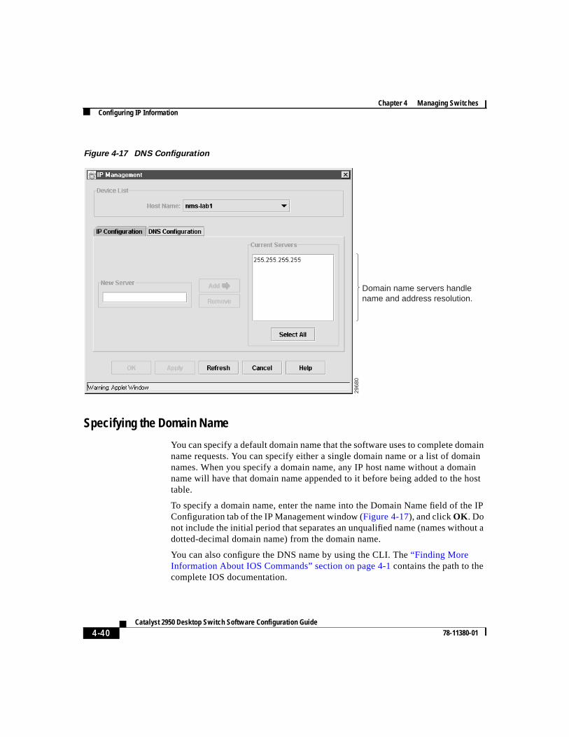
Figure 4-17 DNS Configuration
Specifying the Domain Name
You can specify a default domain name that the software uses to complete domainname requests. You can specify either a single domain name or a list of domainnames. When you specify a domain name, any IP host name without a domainname will have that domain name appended to it before being added to the hosttable.
To specify a domain name, enter the name into the Domain Name field of the IPConfiguration tab of the IP Management window (Figure 4-17), and clickOK . Donot include the initial period that separates an unqualified name (names without adotted-decimal domain name) from the domain name.
You can also configure the DNS name by using the CLI. The“Finding MoreInformation About IOS Commands” section on page 4-1contains the path to thecomplete IOS documentation.
2968
0
Domain name servers handle name and address resolution.
4-41Catalyst 2950 Desktop Switch Software Configuration Guide
78-11380-01
Chapter 4 Managing SwitchesConfiguring SNMP
Specifying a Name Server
You can specify up to six hosts that can function as a name server to supply nameinformation for the DNS. Enter the IP address into the New Server field, and clickAdd.
Enabling the DNS
If your network devices require connectivity with devices in networks for whichyou do not control name assignment, you can assign device names that uniquelyidentify your devices within the entire internetwork. The Internet’s global namingscheme, the DNS, accomplishes this task. This service is enabled by default.
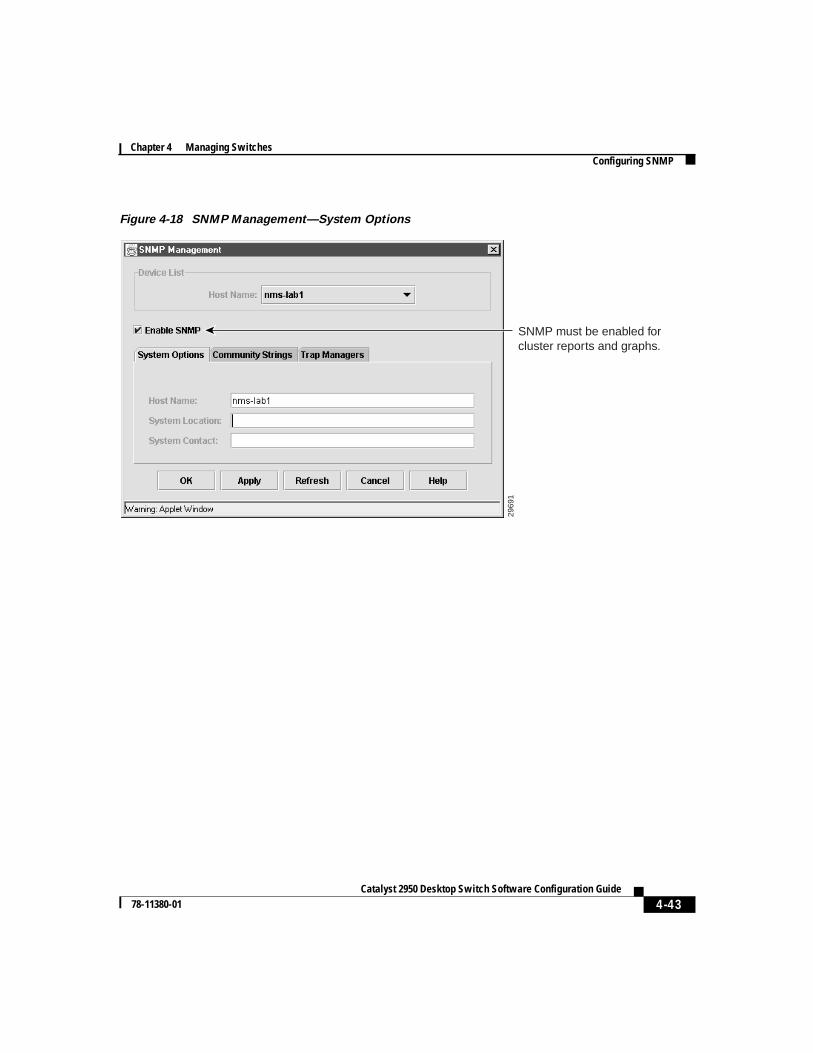
Configuring SNMPUse the SNMP Management window (Figure 4-18) to configure your switch forSNMP management. If your switch is part of a cluster, the clustering software canchange SNMP parameters (such as host names) when the cluster is created. If youare configuring a cluster for SNMP, see the“Configuring SNMP for a Cluster”section on page 3-59.
You can use this window to perform the following tasks:
• Disabling and enabling SNMP.
• Entering general information about the switch.
• Entering community strings that serve as passwords for SNMP messages.
• Entering trap managers and their community strings to receive traps (alerts)about switch activity.
• Setting the classes of traps a trap manager receives.
To display this window, selectSystem > SNMP Configurationfrom the menubar.
Chapter 4 Managing SwitchesConfiguring SNMP
4-42Catalyst 2950 Desktop Switch Software Configuration Guide
78-11380-01
Disabling and Enabling SNMPSNMP is enabled by default and must be enabled for Cluster Managementfeatures to work properly. If you deselectEnable SNMPand clickApply, SNMPis disabled, and the SNMP parameters are disabled. For information on SNMPand Cluster Management, see“Managing Cluster Switches Through SNMP”section on page 2-37.
SNMP is always enabled for 1900 and 2820 switches.
Entering Community StringsCommunity strings serve as passwords for SNMP messages to permit access tothe agent on the switch. If you are entering community strings for a clustermember, see the“Configuring Community Strings for Cluster Switches” sectionon page 3-60. You can enter community strings with the following characteristics:
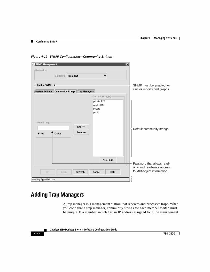
Use the Community Strings tab (Figure 4-19) to add and remove communitystrings. You can also use the CLI to configure SNMP community strings. The“Finding More Information About IOS Commands” section on page 4-1containsthe path to the complete IOS documentation.
Read-only (RO) Requests accompanied by the string can display MIB-objectinformation.
Read-write (RW) Requests accompanied by the string can display MIB-objectinformation and set MIB objects.
4-43Catalyst 2950 Desktop Switch Software Configuration Guide
78-11380-01
Chapter 4 Managing SwitchesConfiguring SNMP
Figure 4-18 SNMP Management—System Options
2969
1
SNMP must be enabled for cluster reports and graphs.
Chapter 4 Managing SwitchesConfiguring SNMP
4-44Catalyst 2950 Desktop Switch Software Configuration Guide
78-11380-01
Figure 4-19 SNMP Configuration—Community Strings
Adding Trap ManagersA trap manager is a management station that receives and processes traps. Whenyou configure a trap manager, community strings for each member switch mustbe unique. If a member switch has an IP address assigned to it, the management
5461
6Default community strings.
SNMP must be enabled for cluster reports and graphs.
Password that allows read-only and read-write access to MIB-object information.
4-45Catalyst 2950 Desktop Switch Software Configuration Guide
78-11380-01
Chapter 4 Managing SwitchesConfiguring SNMP
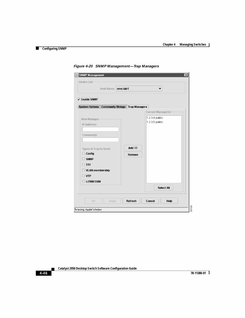
station accesses the switch by using its assigned IP address. Use the TrapManagers tab (Figure 4-20) to configure trap managers and enter trap managercommunity strings.
By default, no trap manager is defined, and no traps are issued. Select a check boxto enable one of the following classes of traps:
Config Generate traps whenever the switch configurationchanges.
SNMP Generate the supported SNMP traps.
TTY Generate traps when the switch starts a managementconsole CLI session.
VLAN membership Generate a trap for each VLAN Membership PolicyServer (VMPS) change.
VTP Generate a trap for each VLAN Trunk Protocol (VTP)change.
C2900/C3500 Generate the switch-specific traps. These traps are in theprivate enterprise-specific MIB.
Chapter 4 Managing SwitchesConfiguring SNMP
4-46Catalyst 2950 Desktop Switch Software Configuration Guide
78-11380-01
Figure 4-20 SNMP Management—Trap Managers
2970
0
4-47Catalyst 2950 Desktop Switch Software Configuration Guide
78-11380-01
Chapter 4 Managing SwitchesManaging the ARP Table
CLI: Adding a Trap ManagerBeginning in privileged EXEC mode, follow these steps to add a trap manager andcommunity string:
The“Finding More Information About IOS Commands” section on page 4-1contains the path to the complete IOS documentation.
Managing the ARP TableTo communicate with a device (on Ethernet, for example), the software first mustdetermine the 48-bit MAC or local data link address of that device. The processof determining the local data link address from an IP address is calledaddressresolution.
The Address Resolution Protocol (ARP) associates a host IP address with thecorresponding media or MAC addresses and VLAN ID. Taking an IP address asinput, ARP determines the associated MAC address. Once a MAC address isdetermined, the IP-MAC address association is stored in an ARP cache for rapidretrieval. Then the IP datagram is encapsulated in a link-layer frame and sent overthe network. Encapsulation of IP datagrams and ARP requests and replies onIEEE 802 networks other than Ethernet is specified by the Subnetwork AccessProtocol (SNAP). By default, standard Ethernet-style ARP encapsulation(represented by thearpa keyword) is enabled on the IP interface.
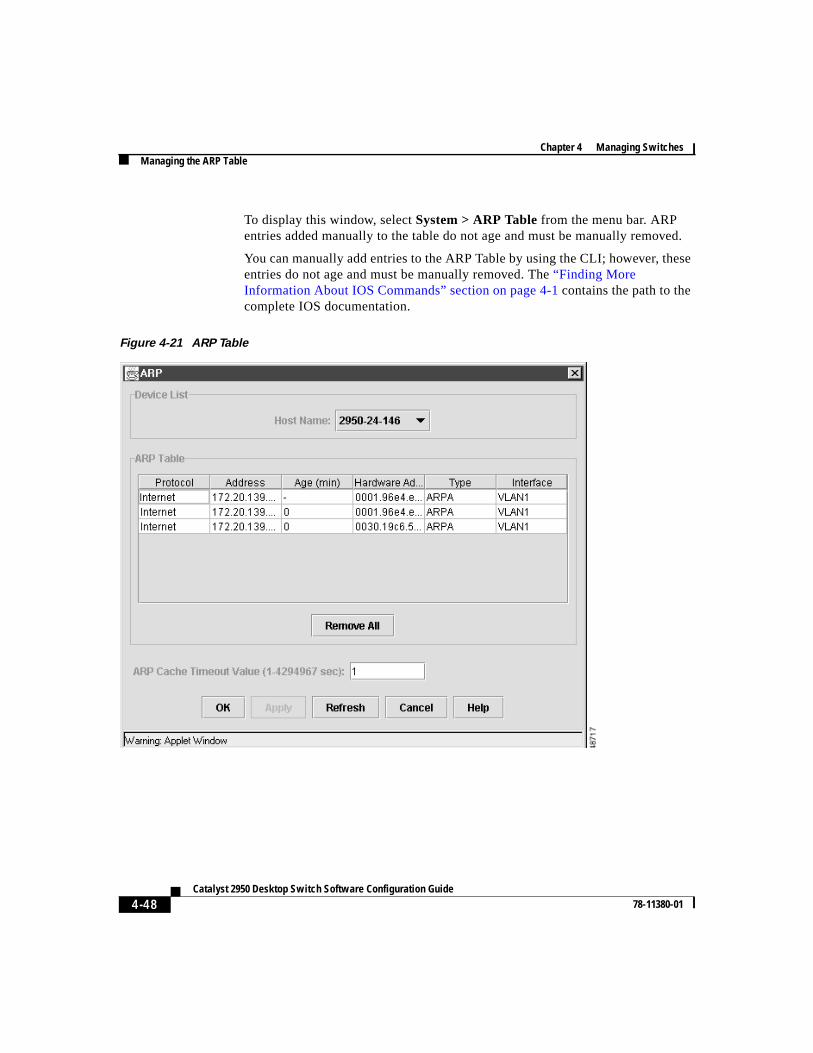
Use the ARP Table window (Figure 4-21) to display the table and change thetimeout value.
Command Purpose
Step 1 config terminal Enter global configuration mode.
Step 2 snmp-server host 172.2.128.263traps1 snmp vlan-membership
Enter the trap manager IP address,community string, and the traps to generate.
Step 3 end Return to privileged EXEC mode.
Step 4 show running-config Verify that the information was enteredcorrectly by displaying the runningconfiguration.
Chapter 4 Managing SwitchesManaging the ARP Table
4-48Catalyst 2950 Desktop Switch Software Configuration Guide
78-11380-01
To display this window, selectSystem > ARP Tablefrom the menu bar. ARPentries added manually to the table do not age and must be manually removed.
You can manually add entries to the ARP Table by using the CLI; however, theseentries do not age and must be manually removed. The“Finding MoreInformation About IOS Commands” section on page 4-1contains the path to thecomplete IOS documentation.
Figure 4-21 ARP Table
4-49Catalyst 2950 Desktop Switch Software Configuration Guide
78-11380-01
Chapter 4 Managing SwitchesManaging the MAC Address Tables
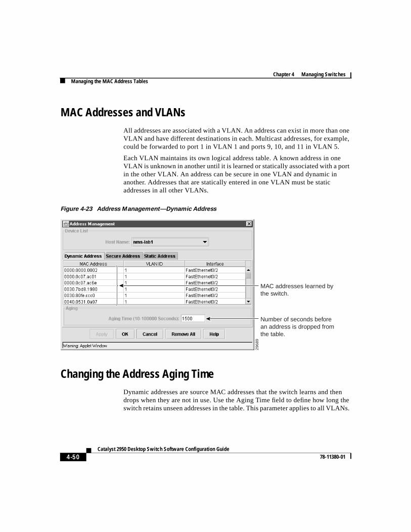
Managing the MAC Address TablesUse the Address Management window (Figure 4-23) to manage the MAC addresstables that the switch uses to forward traffic between ports. All MAC addresses inthe address tables are associated with one or more ports. These MAC tablesinclude the following types of addresses:
• Dynamic address: a source MAC address that the switch learns and then dropswhen it is not in use.
• Secure address: a manually entered unicast address that is usually associatedwith a secure port. Secure addresses do not age.
• Static address: a manually entered unicast or multicast address that does notage and that is not lost when the switch resets.
To display this window, selectSecurity > Address Managementfrom the menubar.
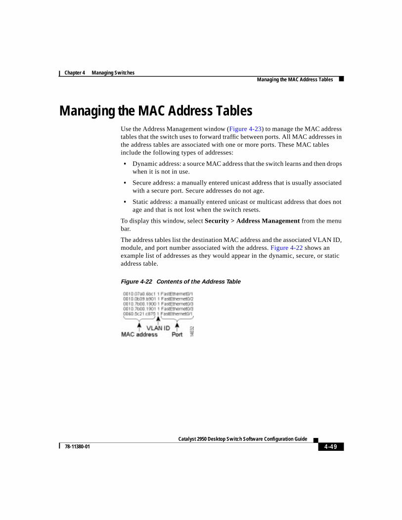
The address tables list the destination MAC address and the associated VLAN ID,module, and port number associated with the address.Figure 4-22 shows anexample list of addresses as they would appear in the dynamic, secure, or staticaddress table.
Figure 4-22 Contents of the Address Table
Chapter 4 Managing SwitchesManaging the MAC Address Tables
4-50Catalyst 2950 Desktop Switch Software Configuration Guide
78-11380-01
MAC Addresses and VLANsAll addresses are associated with a VLAN. An address can exist in more than oneVLAN and have different destinations in each. Multicast addresses, for example,could be forwarded to port 1 in VLAN 1 and ports 9, 10, and 11 in VLAN 5.
Each VLAN maintains its own logical address table. A known address in oneVLAN is unknown in another until it is learned or statically associated with a portin the other VLAN. An address can be secure in one VLAN and dynamic inanother. Addresses that are statically entered in one VLAN must be staticaddresses in all other VLANs.
Figure 4-23 Address Management—Dynamic Address
Changing the Address Aging TimeDynamic addresses are source MAC addresses that the switch learns and thendrops when they are not in use. Use the Aging Time field to define how long theswitch retains unseen addresses in the table. This parameter applies to all VLANs.
2968
9
Number of seconds before an address is dropped from the table.
MAC addresses learned by the switch.
4-51Catalyst 2950 Desktop Switch Software Configuration Guide
78-11380-01
Chapter 4 Managing SwitchesManaging the MAC Address Tables
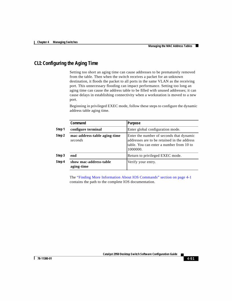
CLI: Configuring the Aging Time
Setting too short an aging time can cause addresses to be prematurely removedfrom the table. Then when the switch receives a packet for an unknowndestination, it floods the packet to all ports in the same VLAN as the receivingport. This unnecessary flooding can impact performance. Setting too long anaging time can cause the address table to be filled with unused addresses; it cancause delays in establishing connectivity when a workstation is moved to a newport.
Beginning in privileged EXEC mode, follow these steps to configure the dynamicaddress table aging time.
The“Finding More Information About IOS Commands” section on page 4-1contains the path to the complete IOS documentation.
Command Purpose
Step 1 configure terminal Enter global configuration mode.
Step 2 mac-address-table aging-timeseconds
Enter the number of seconds that dynamicaddresses are to be retained in the addresstable. You can enter a number from 10 to1000000.
Step 3 end Return to privileged EXEC mode.
Step 4 show mac-address-tableaging-time
Verify your entry.
Chapter 4 Managing SwitchesManaging the MAC Address Tables
4-52Catalyst 2950 Desktop Switch Software Configuration Guide
78-11380-01
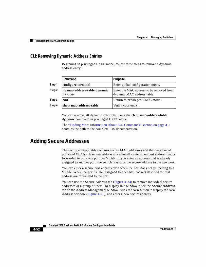
CLI: Removing Dynamic Address Entries
Beginning in privileged EXEC mode, follow these steps to remove a dynamicaddress entry:
You can remove all dynamic entries by using theclear mac-address-tabledynamic command in privileged EXEC mode.
The“Finding More Information About IOS Commands” section on page 4-1contains the path to the complete IOS documentation.
Adding Secure AddressesThe secure address table contains secure MAC addresses and their associatedports and VLANs. A secure address is a manually entered unicast address that isforwarded to only one port per VLAN. If you enter an address that is alreadyassigned to another port, the switch reassigns the secure address to the new port.
You can enter a secure port address even when the port does not yet belong to aVLAN. When the port is later assigned to a VLAN, packets destined for thataddress are forwarded to the port.
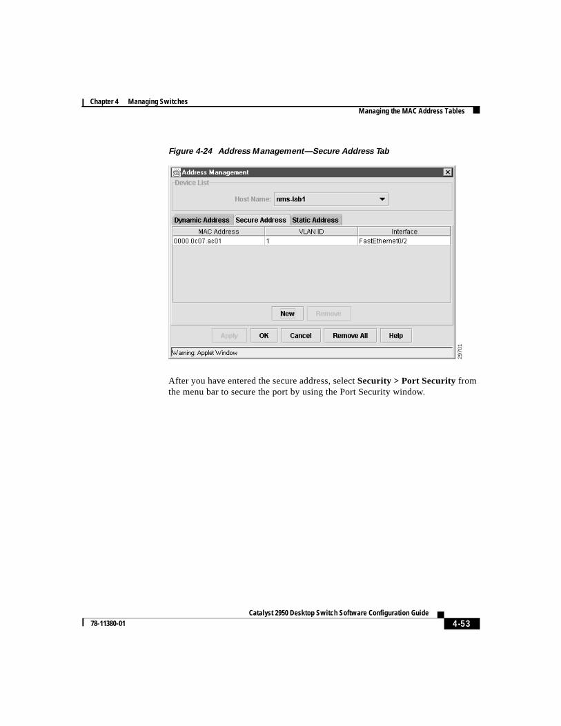
You can use the Secure Address tab (Figure 4-24) to remove individual secureaddresses or a group of them. To display this window, click theSecure Addresstab on the Address Management window. Click theNewbutton to display the NewAddress window (Figure 4-25), and enter a new secure address.
Command Purpose
Step 1 configure terminal Enter global configuration mode.
Step 2 no mac-address-table dynamichw-addr
Enter the MAC address to be removed fromdynamic MAC address table.
Step 3 end Return to privileged EXEC mode.
Step 4 show mac-address-table Verify your entry.
4-53Catalyst 2950 Desktop Switch Software Configuration Guide
78-11380-01
Chapter 4 Managing SwitchesManaging the MAC Address Tables
Figure 4-24 Address Management—Secure Address Tab
After you have entered the secure address, selectSecurity > Port Security fromthe menu bar to secure the port by using the Port Security window.
2970
1
Chapter 4 Managing SwitchesManaging the MAC Address Tables
4-54Catalyst 2950 Desktop Switch Software Configuration Guide
78-11380-01
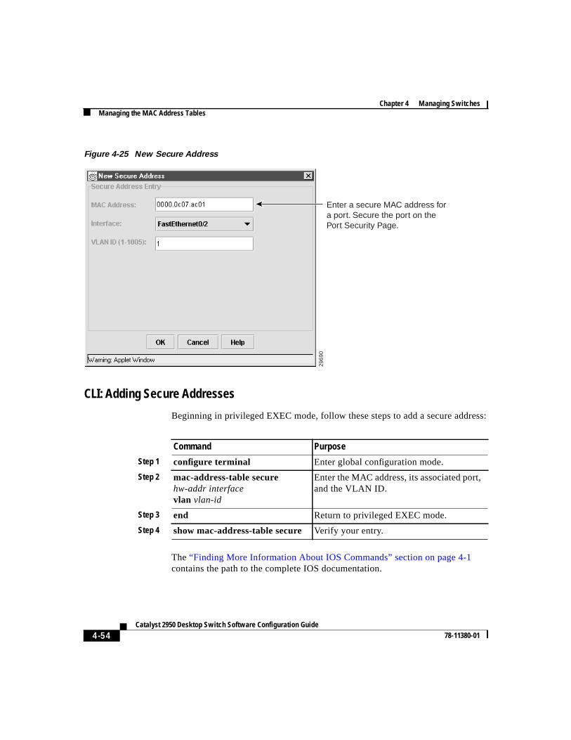
Figure 4-25 New Secure Address
CLI: Adding Secure Addresses
Beginning in privileged EXEC mode, follow these steps to add a secure address:
The“Finding More Information About IOS Commands” section on page 4-1contains the path to the complete IOS documentation.
2969
0
Enter a secure MAC address for a port. Secure the port on the Port Security Page.
Command Purpose
Step 1 configure terminal Enter global configuration mode.
Step 2 mac-address-table securehw-addr interfacevlan vlan-id
Enter the MAC address, its associated port,and the VLAN ID.
Step 3 end Return to privileged EXEC mode.
Step 4 show mac-address-table secure Verify your entry.
4-55Catalyst 2950 Desktop Switch Software Configuration Guide
78-11380-01
Chapter 4 Managing SwitchesManaging the MAC Address Tables
CLI: Removing Secure Addresses
Beginning in privileged EXEC mode, follow these steps to remove a secureaddress:
You can remove all secure addresses by using theclear mac-address-tablesecure command in privileged EXEC mode.
The“Finding More Information About IOS Commands” section on page 4-1contains the path to the complete IOS documentation.
Adding and Removing Static AddressesA static address has the following characteristics:
• It is manually entered in the address table and must be manually removed.
• It can be a unicast or multicast address.
• It does not age and is retained when the switch restarts.
By clicking theStatic Addresstab on the Address Management window(Figure 4-23), you can add and remove static addresses. You can also define theforwarding behavior for the static address. ClickForwarding to display theModify Static Forwarding window (Figure 4-26).
On the Modify Static Forwarding window, you determine how a port that receivesa packet forwards it to another port for transmission. Because all ports areassociated with at least one VLAN, the switch acquires the VLAN ID for theaddress from the ports that you select on the forwarding map.
Command Purpose
Step 1 configure terminal Enter global configuration mode.
Step 2 no mac-address-table securehw-addrvlan vlan-id
Enter the secure MAC address, itsassociated port, and the VLAN ID to beremoved.
Step 3 end Return to privileged EXEC mode.
Step 4 show mac-address-table secure Verify your entry.
Chapter 4 Managing SwitchesManaging the MAC Address Tables
4-56Catalyst 2950 Desktop Switch Software Configuration Guide
78-11380-01
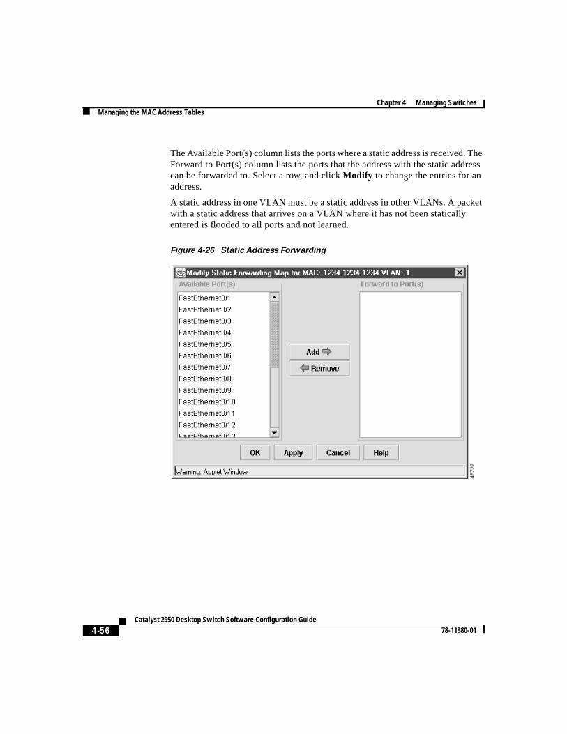
The Available Port(s) column lists the ports where a static address is received. TheForward to Port(s) column lists the ports that the address with the static addresscan be forwarded to. Select a row, and clickModify to change the entries for anaddress.
A static address in one VLAN must be a static address in other VLANs. A packetwith a static address that arrives on a VLAN where it has not been staticallyentered is flooded to all ports and not learned.
Figure 4-26 Static Address Forwarding
4-57Catalyst 2950 Desktop Switch Software Configuration Guide
78-11380-01
Chapter 4 Managing SwitchesManaging the MAC Address Tables
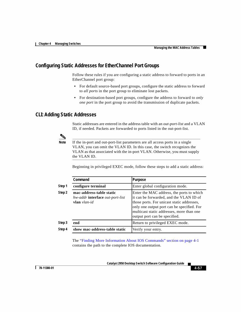
Configuring Static Addresses for EtherChannel Port Groups
Follow these rules if you are configuring a static address to forward to ports in anEtherChannel port group:
• For default source-based port groups, configure the static address to forwardto all ports in the port group to eliminate lost packets.
• For destination-based port groups, configure the address to forward toonlyone port in the port group to avoid the transmission of duplicate packets.
CLI: Adding Static Addresses
Static addresses are entered in the address table with anout-port-listand a VLANID, if needed. Packets are forwarded to ports listed in the out-port-list.
Note If the in-port and out-port-list parameters are all access ports in a singleVLAN, you can omit the VLAN ID. In this case, the switch recognizes theVLAN as that associated with the in-port VLAN. Otherwise, you must supplythe VLAN ID.
Beginning in privileged EXEC mode, follow these steps to add a static address:
The“Finding More Information About IOS Commands” section on page 4-1contains the path to the complete IOS documentation.
Command Purpose
Step 1 configure terminal Enter global configuration mode.
Step 2 mac-address-table statichw-addrinterface out-port-listvlan vlan-id
Enter the MAC address, the ports to whichit can be forwarded, and the VLAN ID ofthose ports. For unicast static addresses,only one output port can be specified. Formulticast static addresses, more than oneoutput port can be specified.
Step 3 end Return to privileged EXEC mode.
Step 4 show mac-address-table static Verify your entry.
Chapter 4 Managing SwitchesEnabling Port Security
4-58Catalyst 2950 Desktop Switch Software Configuration Guide
78-11380-01
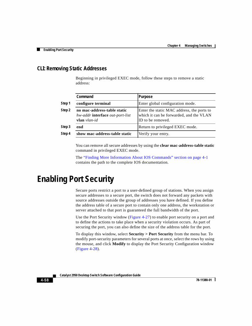
CLI: Removing Static Addresses
Beginning in privileged EXEC mode, follow these steps to remove a staticaddress:
You can remove all secure addresses by using theclear mac-address-table staticcommand in privileged EXEC mode.
The“Finding More Information About IOS Commands” section on page 4-1contains the path to the complete IOS documentation.
Enabling Port SecuritySecure ports restrict a port to a user-defined group of stations. When you assignsecure addresses to a secure port, the switch does not forward any packets withsource addresses outside the group of addresses you have defined. If you definethe address table of a secure port to contain only one address, the workstation orserver attached to that port is guaranteed the full bandwidth of the port.
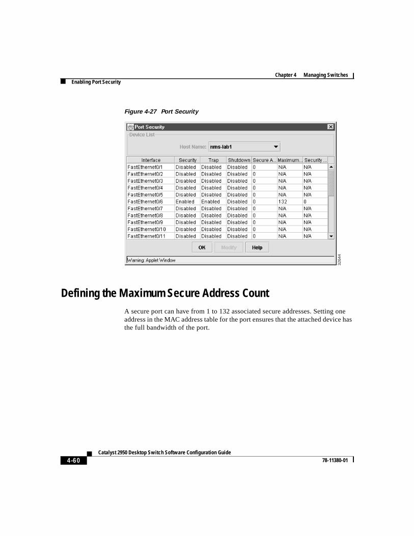
Use the Port Security window (Figure 4-27) to enable port security on a port andto define the actions to take place when a security violation occurs. As part ofsecuring the port, you can also define the size of the address table for the port.
To display this window, selectSecurity > Port Security from the menu bar. Tomodify port-security parameters for several ports at once, select the rows by usingthe mouse, and clickModify to display the Port Security Configuration window(Figure 4-28).
Command Purpose
Step 1 configure terminal Enter global configuration mode.
Step 2 no mac-address-table statichw-addrinterface out-port-listvlan vlan-id
Enter the static MAC address, the ports towhich it can be forwarded, and the VLANID to be removed.
Step 3 end Return to privileged EXEC mode.
Step 4 show mac-address-table static Verify your entry.
4-59Catalyst 2950 Desktop Switch Software Configuration Guide
78-11380-01
Chapter 4 Managing SwitchesEnabling Port Security
Secure ports generate address-security violations under the following conditions:
• The address table of a secure port is full and the address of an incomingpacket is not found in the table.
• An incoming packet has a source address assigned as a secure address onanother port.
Limiting the number of devices that can connect to a secure port has the followingadvantages:
• Dedicated bandwidth—If the size of the address table is set to 1, the attacheddevice is guaranteed the full bandwidth of the port.
• Added security—Unknown devices cannot connect to the port.
The following fields validate port security or indicate security violations:
For the restrictions that apply to secure ports, see the“Managing ConfigurationConflicts” section on page 4-2.
Interface Port to secure.
Security Enable port security on the port.
Trap Issue a trap when an address-security violation occurs.
Shutdown Port Disable the port when an address-security violation occurs.
SecureAddresses
Number of addresses in the address table for this port. Secureports have at least one in this field.
Max Addresses Number of addresses that the address table for the port cancontain.
Security Rejects The number of unauthorized addresses seen on the port.
Chapter 4 Managing SwitchesEnabling Port Security
4-60Catalyst 2950 Desktop Switch Software Configuration Guide
78-11380-01
Figure 4-27 Port Security
Defining the Maximum Secure Address CountA secure port can have from 1 to 132 associated secure addresses. Setting oneaddress in the MAC address table for the port ensures that the attached device hasthe full bandwidth of the port.
3264
4
4-61Catalyst 2950 Desktop Switch Software Configuration Guide
78-11380-01
Chapter 4 Managing SwitchesEnabling Port Security
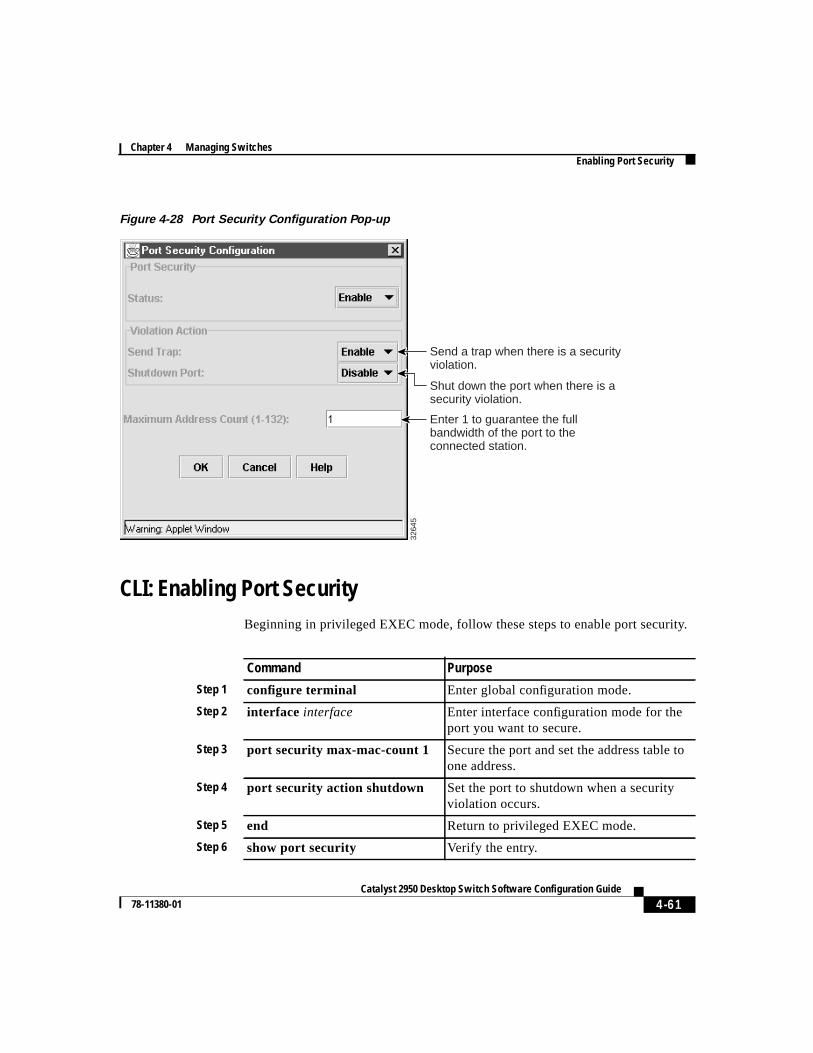
Figure 4-28 Port Security Configuration Pop-up
CLI: Enabling Port SecurityBeginning in privileged EXEC mode, follow these steps to enable port security.
3264
5
Send a trap when there is a security violation.
Enter 1 to guarantee the full bandwidth of the port to the connected station.
Shut down the port when there is a security violation.
Command Purpose
Step 1 configure terminal Enter global configuration mode.
Step 2 interface interface Enter interface configuration mode for theport you want to secure.
Step 3 port security max-mac-count 1 Secure the port and set the address table toone address.
Step 4 port security action shutdown Set the port to shutdown when a securityviolation occurs.
Step 5 end Return to privileged EXEC mode.
Step 6 show port security Verify the entry.
Chapter 4 Managing SwitchesConfiguring the Cisco Discovery Protocol
4-62Catalyst 2950 Desktop Switch Software Configuration Guide
78-11380-01
“Finding More Information About IOS Commands” section on page 4-1containsthe path to the complete IOS documentation.
CLI: Disabling Port SecurityBeginning in privileged EXEC mode, follow these steps to disable port security.
The“Finding More Information About IOS Commands” section on page 4-1contains the path to the complete IOS documentation.
Configuring the Cisco Discovery ProtocolUse the Cisco IOS command-line interface and Cisco Discovery Protocol (CDP)to enable CDP for the switch, set global CDP parameters, and display informationabout neighboring Cisco devices.
CDP enables the Cluster Management Suite to display a graphical view of thenetwork. For example, the switch uses CDP to find cluster candidates andmaintain information about cluster members and other devices up to threecluster-enabled devices away from the command switch.
If necessary, you can configure CDP to discover switches running the ClusterManagement Suite up to seven devices away from the command switch. Devicesthat do not run clustering software display as edge devices, and no deviceconnected to them can be discovered by CDP.
Command Purpose
Step 1 configure terminal Enter global configuration mode.
Step 2 interface interface Enter interface configuration mode for theport you want to unsecure.
Step 3 no port security Disable port security
Step 4 end Return to privileged EXEC mode.
Step 5 show port security Verify the entry
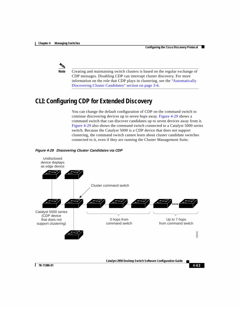
4-63Catalyst 2950 Desktop Switch Software Configuration Guide
78-11380-01
Chapter 4 Managing SwitchesConfiguring the Cisco Discovery Protocol
Note Creating and maintaining switch clusters is based on the regular exchange ofCDP messages. Disabling CDP can interrupt cluster discovery. For moreinformation on the role that CDP plays in clustering, see the“AutomaticallyDiscovering Cluster Candidates” section on page 3-6.
CLI: Configuring CDP for Extended DiscoveryYou can change the default configuration of CDP on the command switch tocontinue discovering devices up to sevenhops away.Figure 4-29 shows acommand switch that can discover candidates up to seven devices away from it.Figure 4-29also shows the command switch connected to a Catalyst 5000 seriesswitch. Because the Catalyst 5000 is a CDP device that does not supportclustering, the command switch cannot learn about cluster candidate switchesconnected to it, even if they are running the Cluster Management Suite.
Figure 4-29 Discovering Cluster Candidates via CDP
Catalyst 5000 series(CDP devicethat does not
support clustering)
Undiscloseddevice displaysas edge device
Cluster command switch
3 hops fromcommand switch
Up to 7 hopsfrom command switch
3301
9
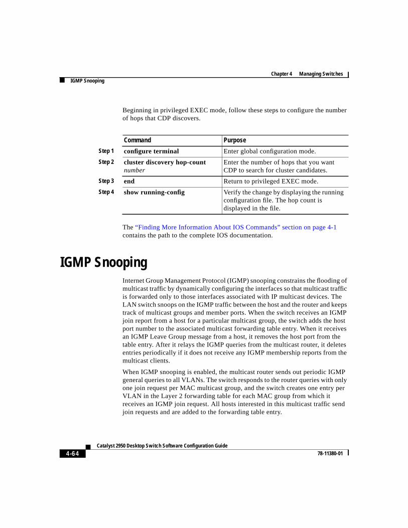
Chapter 4 Managing SwitchesIGMP Snooping
4-64Catalyst 2950 Desktop Switch Software Configuration Guide
78-11380-01
Beginning in privileged EXEC mode, follow these steps to configure the numberof hops that CDP discovers.
The“Finding More Information About IOS Commands” section on page 4-1contains the path to the complete IOS documentation.
IGMP SnoopingInternet Group Management Protocol (IGMP) snooping constrains the flooding ofmulticast traffic by dynamically configuring the interfaces so that multicast trafficis forwarded only to those interfaces associated with IP multicast devices. TheLAN switch snoops on the IGMP traffic between the host and the router and keepstrack of multicast groups and member ports. When the switch receives an IGMPjoin report from a host for a particular multicast group, the switch adds the hostport number to the associated multicast forwarding table entry. When it receivesan IGMP Leave Group message from a host, it removes the host port from thetable entry. After it relays the IGMP queries from the multicast router, it deletesentries periodically if it does not receive any IGMP membership reports from themulticast clients.
When IGMP snooping is enabled, the multicast router sends out periodic IGMPgeneral queries to all VLANs. The switch responds to the router queries with onlyone join request per MAC multicast group, and the switch creates one entry perVLAN in the Layer 2 forwarding table for each MAC group from which itreceives an IGMP join request. All hosts interested in this multicast traffic sendjoin requests and are added to the forwarding table entry.
Command Purpose
Step 1 configure terminal Enter global configuration mode.
Step 2 cluster discovery hop-countnumber
Enter the number of hops that you wantCDP to search for cluster candidates.
Step 3 end Return to privileged EXEC mode.
Step 4 show running-config Verify the change by displaying the runningconfiguration file. The hop count isdisplayed in the file.
4-65Catalyst 2950 Desktop Switch Software Configuration Guide
78-11380-01
Chapter 4 Managing SwitchesIGMP Snooping
Layer 2 multicast groups learned through IGMP snooping are dynamic. However,you can statically configure MAC multicast groups by using theip igmpsnooping vlan staticcommand. If you specify group membership for a multicastgroup address statically, your setting supersedes any automatic manipulation byIGMP snooping. Multicast group membership lists can consist of bothuser-defined and IGMP snooping-learned settings.
Catalyst 2950 switches support a maximum of 255 IP multicast groups andsupport both IGMP version 1 and IGMP version 2.
If a port spanning-tree, a port group, or a VLAN ID change occurs, the IGMPsnooping-learned multicast groups from this port on the VLAN are purged.
In the IP multicast-source-only environment, the switch learns the IP multicastgroup from the IP multicast data stream and only forwards traffic to the multicastrouter ports.
Use the IGMP Snooping window (Figure 4-30) to enable the IGMP snoopingfeature. To display this window, selectDevice > IGMP Snoopingfrom the menubar.
You can use this window to perform the following tasks:
• Enable or disable IGMP snooping
• Enable or disable Immediate-Leave processing
• Join or leave a multicast group
• Configure a multicast router
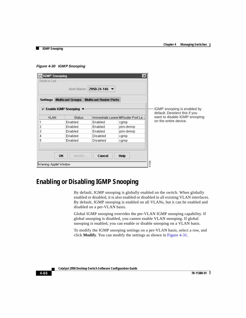
Chapter 4 Managing SwitchesIGMP Snooping
4-66Catalyst 2950 Desktop Switch Software Configuration Guide
78-11380-01
Figure 4-30 IGMP Snooping
Enabling or Disabling IGMP SnoopingBy default, IGMP snooping is globally enabled on the switch. When globallyenabled or disabled, it is also enabled or disabled in all existing VLAN interfaces.By default, IGMP snooping is enabled on all VLANs, but it can be enabled anddisabled on a per-VLAN basis.
Global IGMP snooping overrides the per-VLAN IGMP snooping capability. Ifglobal snooping is disabled, you cannot enable VLAN snooping. If globalsnooping is enabled, you can enable or disable snooping on a VLAN basis.
To modify the IGMP snooping settings on a per-VLAN basis, select a row, andclick Modify . You can modify the settings as shown inFigure 4-31.
IGMP snooping is enabled by default. Deselect this if you want to disable IGMP snooping on the entire device.
4723
6
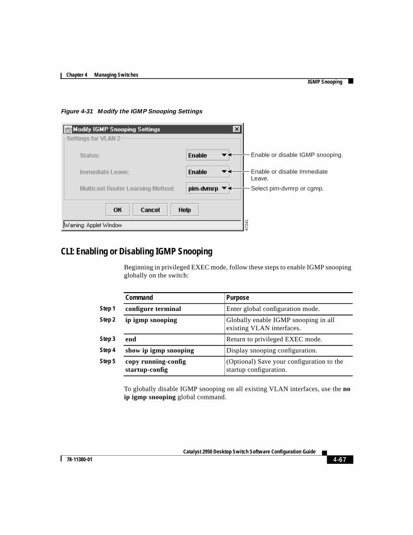
4-67Catalyst 2950 Desktop Switch Software Configuration Guide
78-11380-01
Chapter 4 Managing SwitchesIGMP Snooping
Figure 4-31 Modify the IGMP Snooping Settings
CLI: Enabling or Disabling IGMP Snooping
Beginning in privileged EXEC mode, follow these steps to enable IGMP snoopingglobally on the switch:
To globally disable IGMP snooping on all existing VLAN interfaces, use thenoip igmp snoopingglobal command.
Enable or disable IGMP snooping.
Enable or disable Immediate Leave.
Select pim-dvmrp or cgmp.
4724
1
Command Purpose
Step 1 configure terminal Enter global configuration mode.
Step 2 ip igmp snooping Globally enable IGMP snooping in allexisting VLAN interfaces.
Step 3 end Return to privileged EXEC mode.
Step 4 show ip igmp snooping Display snooping configuration.
Step 5 copy running-configstartup-config
(Optional) Save your configuration to thestartup configuration.
Chapter 4 Managing SwitchesIGMP Snooping
4-68Catalyst 2950 Desktop Switch Software Configuration Guide
78-11380-01
Beginning in privileged EXEC mode, follow these steps to enable IGMP snoopingon a VLAN interface:
To disable IGMP snooping on a VLAN interface, use the global configurationcommandno ip igmp snooping vlanvlan_idfor the specified VLAN number (forexample, vlan1).
The“Finding More Information About IOS Commands” section on page 4-1contains the path to the complete IOS documentation.
CLI: Enabling IGMP Immediate-Leave Processing
When you enable IGMP Immediate-Leave processing, the switch immediatelyremoves a port from the IP multicast group when it detects an IGMP version 2leave message on that port. Immediate-Leave processing allows the switch toremove an interface that sends a leave message from the forwarding table withoutfirst sending out group specific queries to the interface. You should use theImmediate-Leave feature only when there is only a single receiver present onevery port in the VLAN.
Command Purpose
Step 1 configure terminal Enter global configuration mode.
Step 2 ip igmp snooping vlanvlan_id Enable IGMP snooping on the VLANinterface.
Step 3 end Return to privileged EXEC mode.
Step 4 show ip igmp snooping [vlanvlan_id]
Display snooping configuration.
(Optional) vlan_id is the number of theVLAN.
Step 5 copy running-configstartup-config
(Optional) Save your configuration to thestartup configuration.
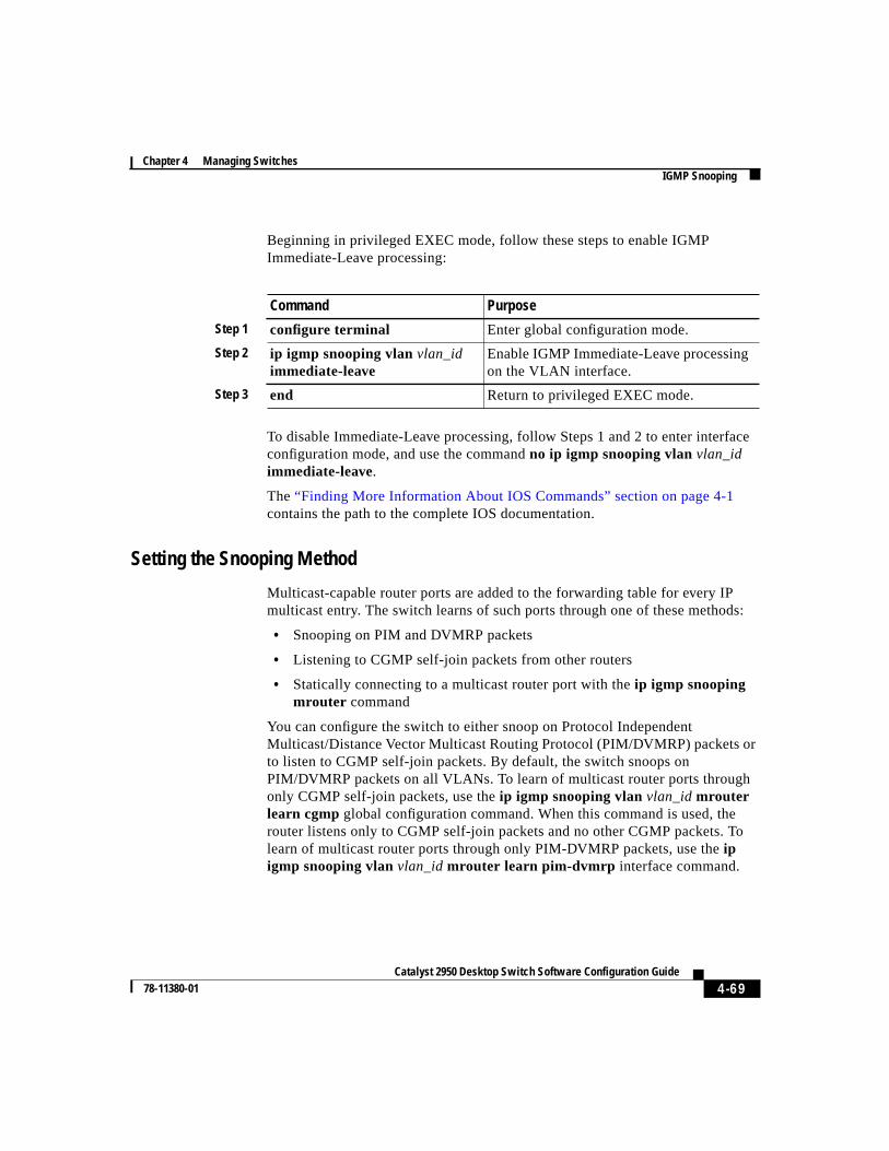
4-69Catalyst 2950 Desktop Switch Software Configuration Guide
78-11380-01
Chapter 4 Managing SwitchesIGMP Snooping
Beginning in privileged EXEC mode, follow these steps to enable IGMPImmediate-Leave processing:
To disable Immediate-Leave processing, follow Steps 1 and 2 to enter interfaceconfiguration mode, and use the commandno ip igmp snooping vlanvlan_idimmediate-leave.
The“Finding More Information About IOS Commands” section on page 4-1contains the path to the complete IOS documentation.
Setting the Snooping Method
Multicast-capable router ports are added to the forwarding table for every IPmulticast entry. The switch learns of such ports through one of these methods:
• Snooping on PIM and DVMRP packets
• Listening to CGMP self-join packets from other routers
• Statically connecting to a multicast router port with theip igmp snoopingmrouter command
You can configure the switch to either snoop on Protocol IndependentMulticast/Distance Vector Multicast Routing Protocol (PIM/DVMRP) packets orto listen to CGMP self-join packets. By default, the switch snoops onPIM/DVMRP packets on all VLANs. To learn of multicast router ports throughonly CGMP self-join packets, use theip igmp snooping vlanvlan_idmrouterlearn cgmp global configuration command. When this command is used, therouter listens only to CGMP self-join packets and no other CGMP packets. Tolearn of multicast router ports through only PIM-DVMRP packets, use theipigmp snooping vlanvlan_id mrouter learn pim-dvmrp interface command.
Command Purpose
Step 1 configure terminal Enter global configuration mode.
Step 2 ip igmp snooping vlanvlan_idimmediate-leave
Enable IGMP Immediate-Leave processingon the VLAN interface.
Step 3 end Return to privileged EXEC mode.
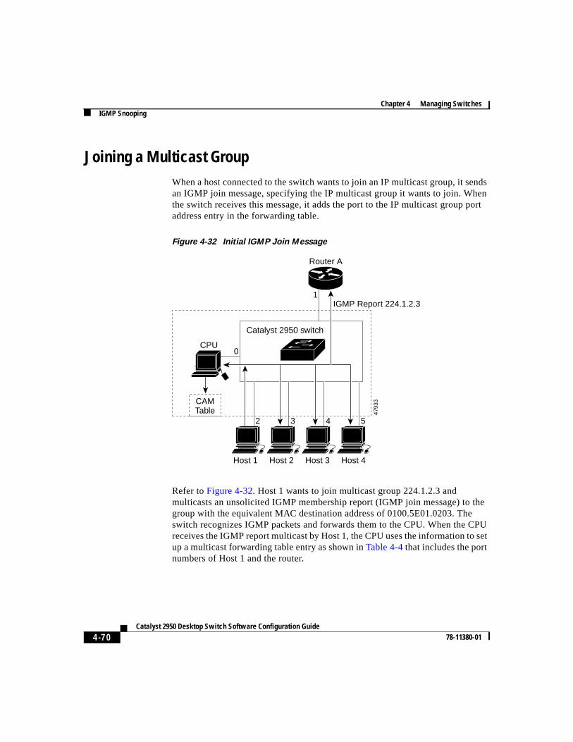
Chapter 4 Managing SwitchesIGMP Snooping
4-70Catalyst 2950 Desktop Switch Software Configuration Guide
78-11380-01
Joining a Multicast GroupWhen a host connected to the switch wants to join an IP multicast group, it sendsan IGMP join message, specifying the IP multicast group it wants to join. Whenthe switch receives this message, it adds the port to the IP multicast group portaddress entry in the forwarding table.
Figure 4-32 Initial IGMP Join Message
Refer toFigure 4-32. Host 1 wants to join multicast group 224.1.2.3 andmulticasts an unsolicited IGMP membership report (IGMP join message) to thegroup with the equivalent MAC destination address of 0100.5E01.0203. Theswitch recognizes IGMP packets and forwards them to the CPU. When the CPUreceives the IGMP report multicast by Host 1, the CPU uses the information to setup a multicast forwarding table entry as shown inTable 4-4that includes the portnumbers of Host 1 and the router.
CAMTable
CPU
Host 1 Host 2 Host 3 Host 4
Router A
IGMP Report 224.1.2.3
Catalyst 2950 switch
1
0
2 3 4 5
4793
3
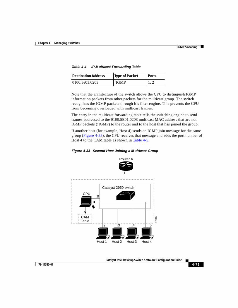
4-71Catalyst 2950 Desktop Switch Software Configuration Guide
78-11380-01
Chapter 4 Managing SwitchesIGMP Snooping
Note that the architecture of the switch allows the CPU to distinguish IGMPinformation packets from other packets for the multicast group. The switchrecognizes the IGMP packets through it’s filter engine. This prevents the CPUfrom becoming overloaded with multicast frames.
The entry in the multicast forwarding table tells the switching engine to sendframes addressed to the 0100.5E01.0203 multicast MAC address that are notIGMP packets (!IGMP) to the router and to the host that has joined the group.
If another host (for example, Host 4) sends an IGMP join message for the samegroup (Figure 4-33), the CPU receives that message and adds the port number ofHost 4 to the CAM table as shown inTable 4-5.
Figure 4-33 Second Host Joining a Multicast Group
Table 4-4 IP Multicast Forwarding Table
Destination Address Type of Packet Ports
0100.5e01.0203 !IGMP 1, 2
CAMTable
CPU
Host 1 Host 2 Host 3 Host 4
Router A
Catalyst 2950 switch
1
0
2 3 4 5
4721
6
Chapter 4 Managing SwitchesIGMP Snooping
4-72Catalyst 2950 Desktop Switch Software Configuration Guide
78-11380-01
Statically Configuring a Host to Join a Group
Ports normally join multicast groups through the IGMP report message, but youcan also statically configure a host on an interface.
Select theMulticast Group tab on the IGMP snooping window (Figure 4-30) toview the current settings. Select the row you want to modify from the MulticastGroups window (Figure 4-34), and clickModify to change the settings. Use theMulticast Groups window (Figure 4-35) to add or remove ports from a multicastgroup.
Table 4-5 Updated Multicast Forwarding Table
Destination Address Type of Packet Ports
0100.5e01.0203 !IGMP 1, 2, 5
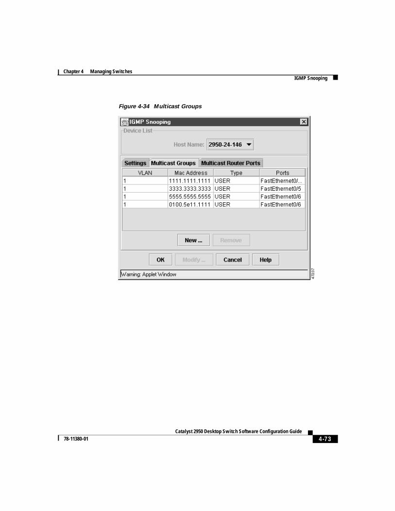
4-73Catalyst 2950 Desktop Switch Software Configuration Guide
78-11380-01
Chapter 4 Managing SwitchesIGMP Snooping
Figure 4-34 Multicast Groups
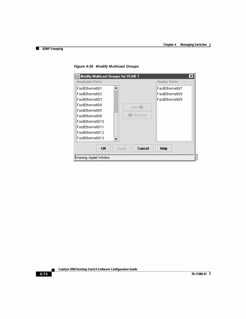
Chapter 4 Managing SwitchesIGMP Snooping
4-74Catalyst 2950 Desktop Switch Software Configuration Guide
78-11380-01
Figure 4-35 Modify Multicast Groups
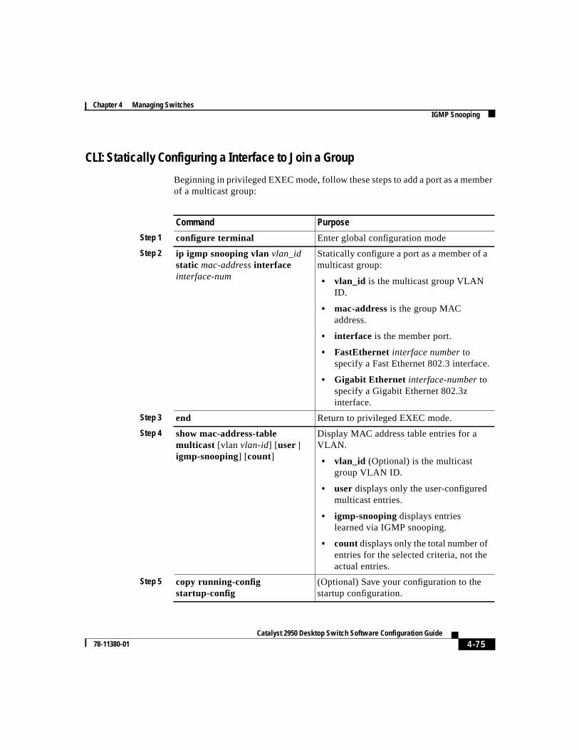
4-75Catalyst 2950 Desktop Switch Software Configuration Guide
78-11380-01
Chapter 4 Managing SwitchesIGMP Snooping
CLI: Statically Configuring a Interface to Join a Group
Beginning in privileged EXEC mode, follow these steps to add a port as a memberof a multicast group:
Command Purpose
Step 1 configure terminal Enter global configuration mode
Step 2 ip igmp snooping vlanvlan_idstatic mac-addressinterfaceinterface-num
Statically configure a port as a member of amulticast group:
• vlan_id is the multicast group VLANID.
• mac-address is the group MACaddress.
• interface is the member port.
• FastEthernet interface numbertospecify a Fast Ethernet 802.3 interface.
• Gigabit Ethernet interface-numbertospecify a Gigabit Ethernet 802.3zinterface.
Step 3 end Return to privileged EXEC mode.
Step 4 show mac-address-tablemulticast [vlan vlan-id] [user |igmp-snooping] [count]
Display MAC address table entries for aVLAN.
• vlan_id (Optional) is the multicastgroup VLAN ID.
• user displays only the user-configuredmulticast entries.
• igmp-snooping displays entrieslearned via IGMP snooping.
• count displays only the total number ofentries for the selected criteria, not theactual entries.
Step 5 copy running-configstartup-config
(Optional) Save your configuration to thestartup configuration.
Chapter 4 Managing SwitchesIGMP Snooping
4-76Catalyst 2950 Desktop Switch Software Configuration Guide
78-11380-01
The“Finding More Information About IOS Commands” section on page 4-1contains the path to the complete IOS documentation.
Leaving a Multicast GroupThe router sends periodic IP multicast general queries, and the switch responds tothese queries with one join response per MAC multicast group. As long as at leastone host in the VLAN needs multicast traffic, the switch responds to the routerqueries, and the router continues forwarding the multicast traffic to the VLAN.The switch only forwards IP multicast group traffic to those hosts listed in theforwarding table for that IP multicast group.
When hosts need to leave a multicast group, they can either ignore the periodicgeneral-query requests sent by the router, or they can send a leave message. Whenthe switch receives a leave message from a host, it sends out a group-specificquery to determine if any devices behind that interface are interested in traffic forthe specific multicast group. If, after a number of queries, the router processorreceives no reports from a VLAN, it removes the group for the VLAN from itsIGMP cache.
Configuring a Multicast Router PortSelect theMulticast Router Port tab on the IGMP snooping window(Figure 4-30) to view the current settings. Select the row that you want to modifyfrom the Multicast Router Ports window (Figure 4-36), and clickModify tochange the settings. Use the Multicast Router Ports window (Figure 4-37) to addor remove ports.
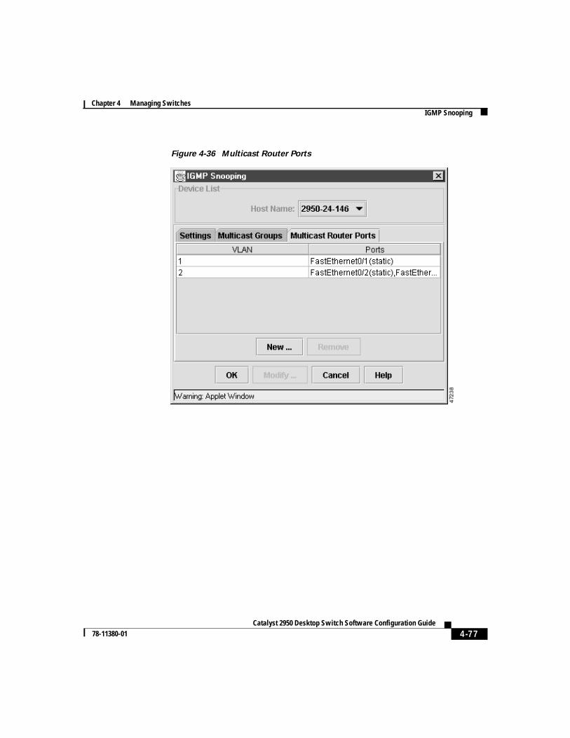
4-77Catalyst 2950 Desktop Switch Software Configuration Guide
78-11380-01
Chapter 4 Managing SwitchesIGMP Snooping
Figure 4-36 Multicast Router Ports
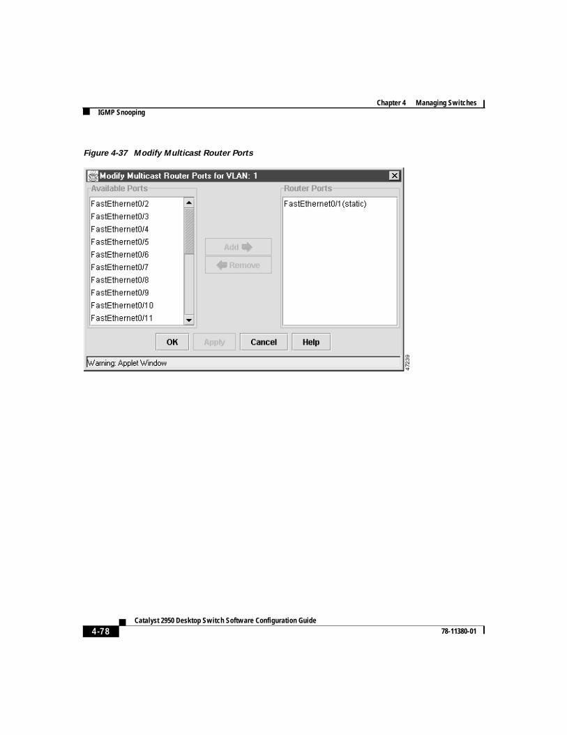
Chapter 4 Managing SwitchesIGMP Snooping
4-78Catalyst 2950 Desktop Switch Software Configuration Guide
78-11380-01
Figure 4-37 Modify Multicast Router Ports
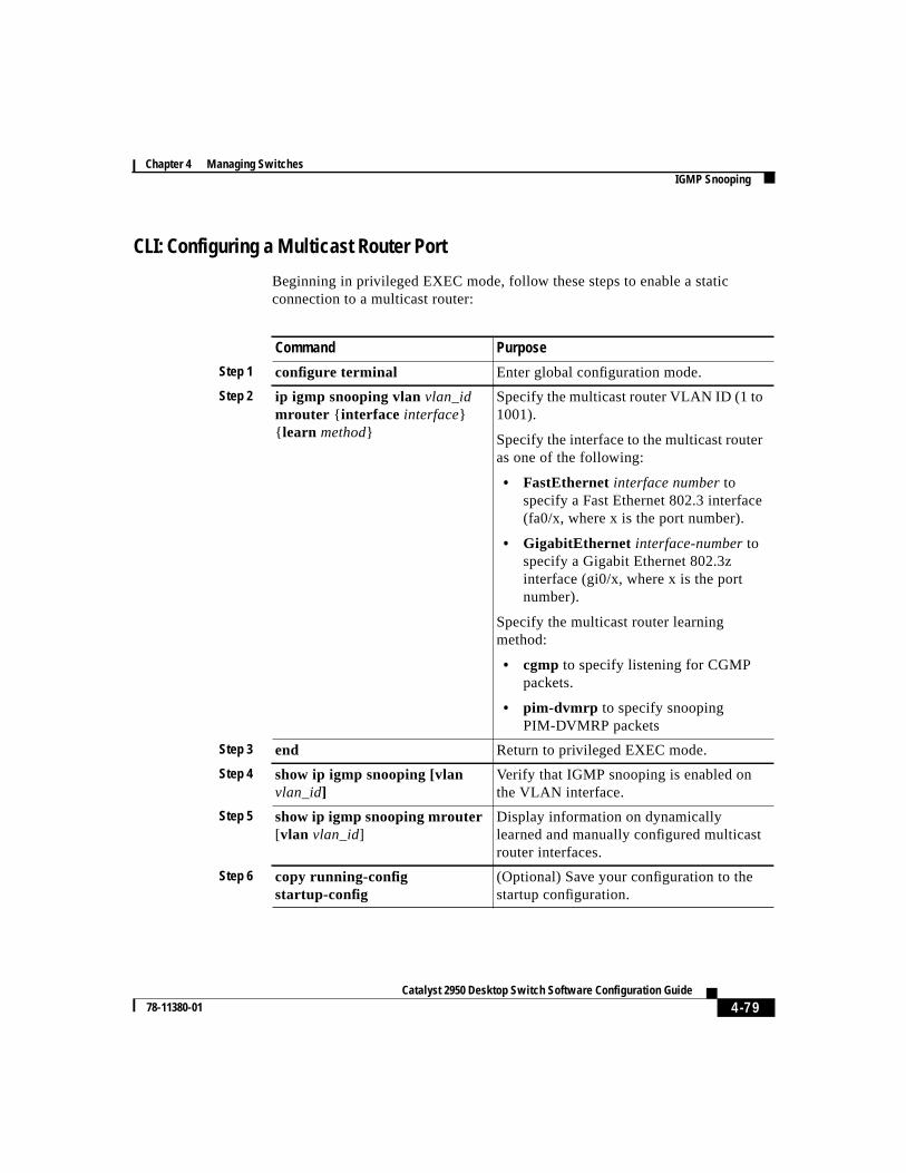
4-79Catalyst 2950 Desktop Switch Software Configuration Guide
78-11380-01
Chapter 4 Managing SwitchesIGMP Snooping
CLI: Configuring a Multicast Router Port
Beginning in privileged EXEC mode, follow these steps to enable a staticconnection to a multicast router:
Command Purpose
Step 1 configure terminal Enter global configuration mode.
Step 2 ip igmp snooping vlanvlan_idmrouter { interface interface}{ learn method}
Specify the multicast router VLAN ID (1 to1001).
Specify the interface to the multicast routeras one of the following:
• FastEthernet interface numbertospecify a Fast Ethernet 802.3 interface(fa0/x, where x is the port number).
• GigabitEthernet interface-numbertospecify a Gigabit Ethernet 802.3zinterface (gi0/x, where x is the portnumber).
Specify the multicast router learningmethod:
• cgmp to specify listening for CGMPpackets.
• pim-dvmrp to specify snoopingPIM-DVMRP packets
Step 3 end Return to privileged EXEC mode.
Step 4 show ip igmp snooping [vlanvlan_id]
Verify that IGMP snooping is enabled onthe VLAN interface.
Step 5 show ip igmp snooping mrouter[vlan vlan_id]
Display information on dynamicallylearned and manually configured multicastrouter interfaces.
Step 6 copy running-configstartup-config
(Optional) Save your configuration to thestartup configuration.
Chapter 4 Managing SwitchesConfiguring the Spanning Tree Protocol
4-80Catalyst 2950 Desktop Switch Software Configuration Guide
78-11380-01
The“Finding More Information About IOS Commands” section on page 4-1contains the path to the complete IOS documentation.
Configuring the Spanning Tree ProtocolSpanning Tree Protocol (STP) provides path redundancy while preventingundesirable loops in the network. Only one active path can exist between any twostations. STP calculates the best loop-free path throughout the network.
Supported STP InstancesYou create an STP instance when you assign an interface to a VLAN. The STPinstance is removed when the last interface is moved to another VLAN. You canconfigure switch and port parameters before an STP instance is created. Theseparameters are applied when the STP instance is created. You can change allVLANs on a switch by using theshow spanning-tree[vlan stp-list] privilegedEXEC command when you enter STP commands through the CLI. For moreinformation, refer to theCatalyst 2950 Desktop Switch Command Reference.
Catalyst 2950 switches support only 64 VLANs. For more information aboutVLANs, seeChapter 5, “Creating and Maintaining VLANs.”
Each VLAN is a separate STP instance. If you have already used up all availableSTP instances on a switch, adding another VLAN anywhere in the VLAN TrunkProtocol (VTP) domain creates a VLAN that is not running STP on that switch.For example, if 64 VLANs are defined in the VTP domain, you can enable STPon those 64 VLANs. The remaining VLANs must operate with STP disabled.
You can disable STP on one of the VLANs where it is running and then enable iton the VLAN where you want it to run. Use theno spanning-tree vlanvlan-idglobal configuration command to disable STP on a specific VLAN, and use thespanning-tree vlanvlan-id global configuration command to enable STP on thedesired VLAN.
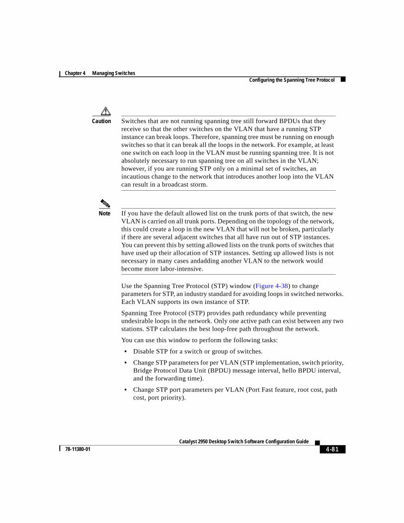
4-81Catalyst 2950 Desktop Switch Software Configuration Guide
78-11380-01
Chapter 4 Managing SwitchesConfiguring the Spanning Tree Protocol
Caution Switches that are not running spanning tree still forward BPDUs that theyreceive so that the other switches on the VLAN that have a running STPinstance can break loops. Therefore, spanning tree must be running on enoughswitches so that it can break all the loops in the network. For example, at leastone switch on each loop in the VLAN must be running spanning tree. It is notabsolutely necessary to run spanning tree on all switches in the VLAN;however, if you are running STP only on a minimal set of switches, anincautious change to the network that introduces another loop into the VLANcan result in a broadcast storm.
Note If you have the default allowed list on the trunk ports of that switch, the newVLAN is carried on all trunk ports. Depending on the topology of the network,this could create a loop in the new VLAN that will not be broken, particularlyif there are several adjacent switches that all have run out of STP instances.You can prevent this by setting allowed lists on the trunk ports of switches thathave used up their allocation of STP instances. Setting up allowed lists is notnecessary in many cases andadding another VLAN to the network wouldbecome more labor-intensive.
Use the Spanning Tree Protocol (STP) window (Figure 4-38) to changeparameters for STP, an industry standard for avoiding loops in switched networks.Each VLAN supports its own instance of STP.
Spanning Tree Protocol (STP) provides path redundancy while preventingundesirable loops in the network. Only one active path can exist between any twostations. STP calculates the best loop-free path throughout the network.
You can use this window to perform the following tasks:
• Disable STP for a switch or group of switches.
• Change STP parameters for per VLAN (STP implementation, switch priority,Bridge Protocol Data Unit (BPDU) message interval, hello BPDU interval,and the forwarding time).
• Change STP port parameters per VLAN (Port Fast feature, root cost, pathcost, port priority).
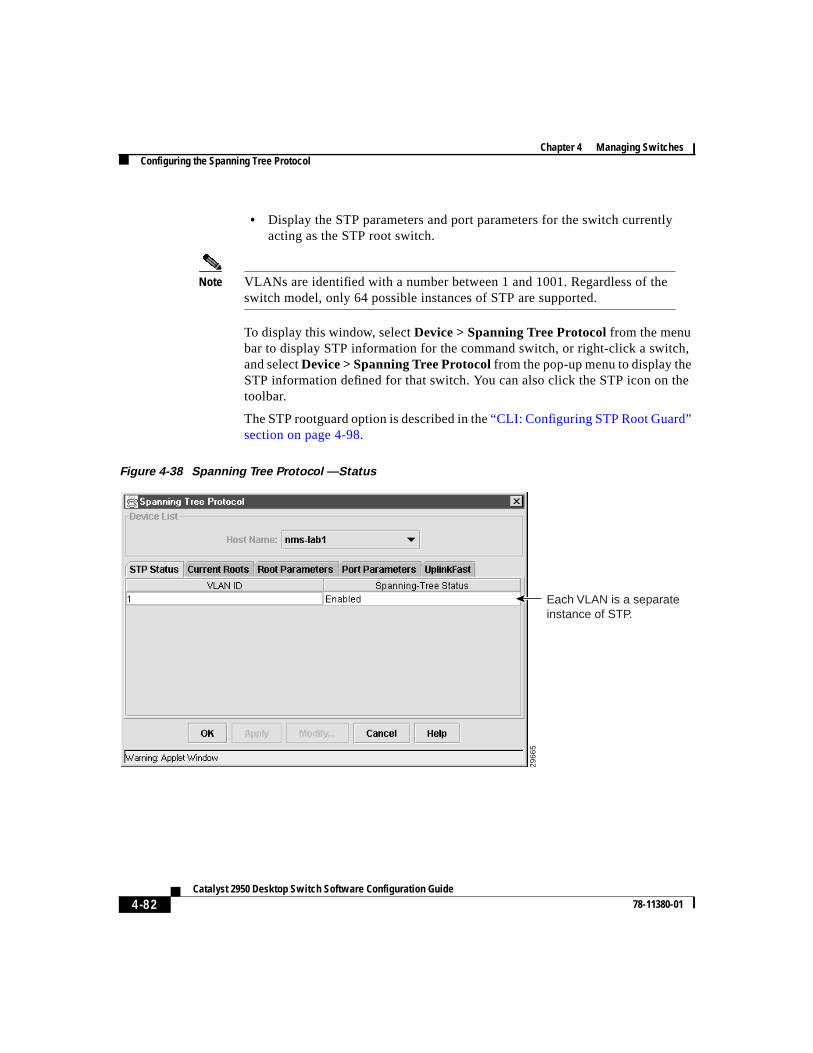
Chapter 4 Managing SwitchesConfiguring the Spanning Tree Protocol
4-82Catalyst 2950 Desktop Switch Software Configuration Guide
78-11380-01
• Display the STP parameters and port parameters for the switch currentlyacting as the STP root switch.
Note VLANs are identified with a number between 1 and 1001. Regardless of theswitch model, only 64 possible instances of STP are supported.
To display this window, selectDevice > Spanning Tree Protocolfrom the menubar to display STP information for the command switch, or right-click a switch,and selectDevice > Spanning Tree Protocolfrom the pop-up menu to display theSTP information defined for that switch. You can also click the STP icon on thetoolbar.
The STP rootguard option is described in the“CLI: Configuring STP Root Guard”section on page 4-98.
Figure 4-38 Spanning Tree Protocol —Status
Each VLAN is a separate instance of STP.
2966
5
4-83Catalyst 2950 Desktop Switch Software Configuration Guide
78-11380-01
Chapter 4 Managing SwitchesConfiguring the Spanning Tree Protocol
Using STP to Support Redundant ConnectivityYou can create a redundant backbone with STP by connecting two of the switchports to another device or to two different devices. STP automatically disables oneport but enables it if the other port is lost. If one link is high-speed and the otherlow-speed, the low-speed link is always disabled. If the speed of the two links isthe same, the port priority and port ID are added together, and STP disables thelink with the lowest value.
You can also create redundant links between switches by using EtherChannel portgroups. For more information on creating port groups, see the“CreatingEtherChannel Port Groups” section on page 4-11.
Accelerating Aging to Retain ConnectivityThe default for aging dynamic addresses is 5 minutes. However, a reconfigurationof the spanning tree can cause many station locations to change. Because thesestations could be unreachable for 5 minutes or more during a reconfiguration, theaddress-aging time is accelerated so that station addresses can be dropped fromthe address table and then relearned. The accelerated aging is the same as theforward-delay parameter value when STP reconfigures.
Because each VLAN is a separate instance of STP, the switch accelerates agingon a per-VLAN basis. A reconfiguration of STP on one VLAN can cause thedynamic addresses learned on that VLAN to be subject to accelerated aging.Dynamic addresses on other VLANs can be unaffected and remain subject to theaging interval entered for the switch.
Disabling STP ProtocolSTP is enabled by default. Disable STP only if you are sure there are no loops inthe network topology.
Caution When STP is disabled and loops are present in the topology, excessive trafficand indefinite packet duplication can drastically reduce network performance.
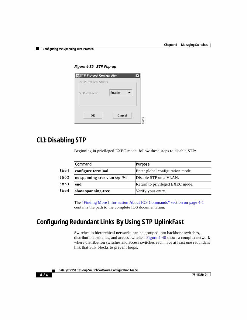
Chapter 4 Managing SwitchesConfiguring the Spanning Tree Protocol
4-84Catalyst 2950 Desktop Switch Software Configuration Guide
78-11380-01
Figure 4-39 STP Pop-up
CLI: Disabling STPBeginning in privileged EXEC mode, follow these steps to disable STP:
The“Finding More Information About IOS Commands” section on page 4-1contains the path to the complete IOS documentation.
Configuring Redundant Links By Using STP UplinkFastSwitches in hierarchical networks can be grouped into backbone switches,distribution switches, and access switches.Figure 4-40shows a complex networkwhere distribution switches and access switches each have at least one redundantlink that STP blocks to prevent loops.
2973
3
Command Purpose
Step 1 configure terminal Enter global configuration mode.
Step 2 no spanning-tree vlanstp-list Disable STP on a VLAN.
Step 3 end Return to privileged EXEC mode.
Step 4 show spanning-tree Verify your entry.
4-85Catalyst 2950 Desktop Switch Software Configuration Guide
78-11380-01
Chapter 4 Managing SwitchesConfiguring the Spanning Tree Protocol
If a switch looses connectivity, the switch begins using the alternate paths as soonas STP selects a new root port. When STP reconfigures the new root port, otherports flood the network with multicast packets, one for each address that waslearned on the port. You can limit these bursts of multicast traffic by reducing themax-update-rate parameter (the default for this parameter is 150 packets persecond). However, if you enter zero, station-learning frames are not generated, sothe STP topology converges more slowly after a loss of connectivity.
STP UplinkFast is an enhancement that accelerates the choice of a new root portwhen a link or switch fails or when STP reconfigures itself. The root porttransitions to the forwarding state immediately without going through thelistening and learning states, as it would with normal STP procedures. UplinkFastis most useful in edge or access switches and might not be appropriate forbackbone devices.
You can change STP parameters by using the UplinkFast tab of the Spanning TreeProtocol window or by using the CLI. The“Configuring the Spanning TreeProtocol” section on page 4-80 describes the use of the Spanning Tree Protocolwindow.
To display this window, selectDevice > Spanning-Tree Protocolfrom the menubar. Then click theUplinkFast tab.
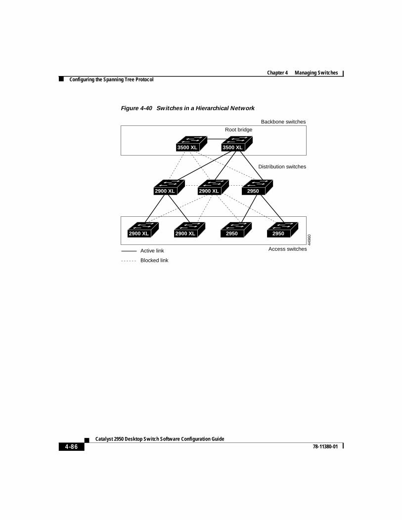
Chapter 4 Managing SwitchesConfiguring the Spanning Tree Protocol
4-86Catalyst 2950 Desktop Switch Software Configuration Guide
78-11380-01
Figure 4-40 Switches in a Hierarchical Network
3500 XL 3500 XL
2900 XL 2900 XL 2950
2900 XL 2900 XL 2950 2950
Active link
Blocked link
Root bridge
Backbone switches
Distribution switches
Access switches
4496
0
4-87Catalyst 2950 Desktop Switch Software Configuration Guide
78-11380-01
Chapter 4 Managing SwitchesConfiguring the Spanning Tree Protocol
CLI: Enabling STP UplinkFastWhen you enable UplinkFast, it is enabled for the entire switch and cannot beenabled for individual VLANs.
Beginning in privileged EXEC mode, follow these steps to configure UplinkFast:
When UplinkFast is enabled, the bridge priority of all VLANs is set to 49152, andthe path cost of all ports and VLAN trunks is increased by 3000. This changereduces the chance that the switch will become the root port. When UplinkFast isdisabled, the bridge priorities of all VLANs and path costs of all ports are set todefault values.
The“Finding More Information About IOS Commands” section on page 4-1contains the path to the complete IOS documentation.
Changing STP Parameters for a VLANTo change STP parameters for a VLAN, selectDevice > Spanning Tree Protocolfrom the menu bar, select the VLAN ID of the STP instance to change, and clickRoot Parameters.
Command Purpose
Step 1 configure terminal Enter global configuration mode.
Step 2 spanning-tree uplinkfastmax-update-ratepkts-per-second
Enable UplinkFast on the switch.
The range is from 0 to 1000 packets persecond; The default is 150.
If you set the rate to 0, station-learningframes are not generated, so the STPtopology converges more slowly after a lossof connectivity.
Step 3 exit Return to privileged EXEC mode.
Step 4 show spanning-tree Verify your entries.
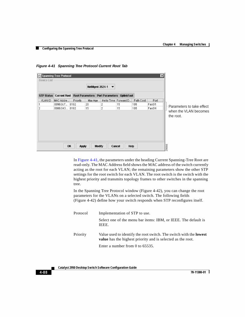
Chapter 4 Managing SwitchesConfiguring the Spanning Tree Protocol
4-88Catalyst 2950 Desktop Switch Software Configuration Guide
78-11380-01
Figure 4-41 Spanning Tree Protocol Current Root Tab
In Figure 4-41, the parameters under the heading Current Spanning-Tree Root areread-only. The MAC Address field shows the MAC address of the switch currentlyacting as the root for each VLAN; the remaining parameters show the other STPsettings for the root switch for each VLAN. The root switch is the switch with thehighest priority and transmits topology frames to other switches in the spanningtree.
In the Spanning Tree Protocol window (Figure 4-42), you can change the rootparameters for the VLANs on a selected switch. The following fields(Figure 4-42) define how your switch responds when STP reconfigures itself.
Parameters to take effect when the VLAN becomes the root.
29
66
6
Protocol Implementation of STP to use.
Select one of the menu bar items: IBM, or IEEE. The default isIEEE.
Priority Value used to identify the root switch. The switch with thelowestvalue has the highest priority and is selected as the root.
Enter a number from 0 to 65535.
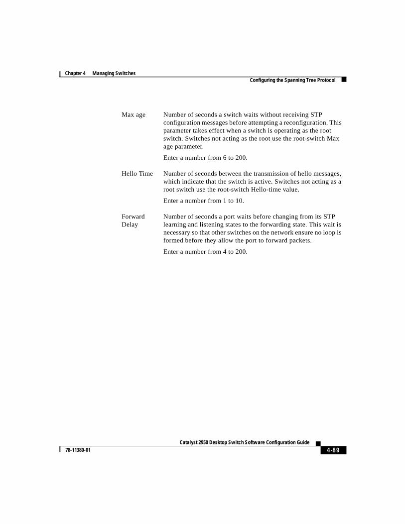
4-89Catalyst 2950 Desktop Switch Software Configuration Guide
78-11380-01
Chapter 4 Managing SwitchesConfiguring the Spanning Tree Protocol
Max age Number of seconds a switch waits without receiving STPconfiguration messages before attempting a reconfiguration. Thisparameter takes effect when a switch is operating as the rootswitch. Switches not acting as the root use the root-switch Maxage parameter.
Enter a number from 6 to 200.
Hello Time Number of seconds between the transmission of hello messages,which indicate that the switch is active. Switches not acting as aroot switch use the root-switch Hello-time value.
Enter a number from 1 to 10.
ForwardDelay
Number of seconds a port waits before changing from its STPlearning and listening states to the forwarding state. This wait isnecessary so that other switches on the network ensure no loop isformed before they allow the port to forward packets.
Enter a number from 4 to 200.
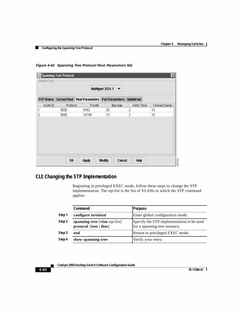
Chapter 4 Managing SwitchesConfiguring the Spanning Tree Protocol
4-90Catalyst 2950 Desktop Switch Software Configuration Guide
78-11380-01
Figure 4-42 Spanning Tree Protocol Root Parameters Tab
CLI: Changing the STP Implementation
Beginning in privileged EXEC mode, follow these steps to change the STPimplementation. Thestp-list is the list of VLANs to which the STP commandapplies.
29
73
4
Command Purpose
Step 1 configure terminal Enter global configuration mode.
Step 2 spanning-tree[vlan stp-list]protocol { ieee | ibm}
Specify the STP implementation to be usedfor a spanning-tree instance.
Step 3 end Return to privileged EXEC mode.
Step 4 show spanning-tree Verify your entry.
4-91Catalyst 2950 Desktop Switch Software Configuration Guide
78-11380-01
Chapter 4 Managing SwitchesConfiguring the Spanning Tree Protocol
The“Finding More Information About IOS Commands” section on page 4-1contains the path to the complete IOS documentation.
CLI: Changing the Switch Priority
Beginning in privileged EXEC mode, follow these steps to change the switchpriority and affect which switch is the root switch. Thestp-list is the list ofVLANs to which the STP command applies.
The“Finding More Information About IOS Commands” section on page 4-1contains the path to the complete IOS documentation.
Command Purpose
Step 1 configure terminal Enter global configuration mode.
Step 2 spanning-tree[vlan stp-list]priority bridge-priority
Configure the switch priority for thespecified spanning-tree instance.
Enter a number from 0 to 65535; the lowerthe number, the more likely the switch willbe chosen as the root switch.
Step 3 end Return to privileged EXEC mode.
Step 4 show spanning-tree Verify your entry.
Chapter 4 Managing SwitchesConfiguring the Spanning Tree Protocol
4-92Catalyst 2950 Desktop Switch Software Configuration Guide
78-11380-01
CLI: Changing the BPDU Message Interval
Beginning in privileged EXEC mode, follow these steps to change the BPDUmessage interval (max age time). Thestp-list is the list of VLANs to which theSTP command applies.
The“Finding More Information About IOS Commands” section on page 4-1contains the path to the complete IOS documentation.
CLI: Changing the Hello BPDU Interval
Beginning in privileged EXEC mode, follow these steps to change the helloBPDU interval (hello time). Thestp-list is the list of VLANs to which the STPcommand applies.
Command Purpose
Step 1 configure terminal Enter global configuration mode.
Step 2 spanning-tree[vlan stp-list]max-ageseconds
Specify the interval between messages thespanning tree receives from the root switch.
The maximum age is the number of seconds aswitch waits without receiving STPconfiguration messages before attempting areconfiguration. Enter a number from 6 to 200.
Step 3 end Return to privileged EXEC mode.
Step 4 show spanning-tree Verify your entry.
Command Purpose
Step 1 configure terminal Enter global configuration mode.
Step 2 spanning-tree[vlan stp-list]hello-time seconds
Specify the interval between hello BPDUs.
Hello messages indicate that the switch isactive. Enter a number from 1 to 10.
Step 3 end Return to privileged EXEC mode.
Step 4 show spanning-tree Verify your entry.
4-93Catalyst 2950 Desktop Switch Software Configuration Guide
78-11380-01
Chapter 4 Managing SwitchesConfiguring the Spanning Tree Protocol
The“Finding More Information About IOS Commands” section on page 4-1contains the path to the complete IOS documentation.
CLI: Changing the Forwarding Delay Time
Beginning in privileged EXEC mode, follow these steps to change the forwardingdelay time. Thestp-list is the list of VLANs to which the STP command applies.
The“Finding More Information About IOS Commands” section on page 4-1contains the path to the complete IOS documentation.
Changing STP Port ParametersThe ports listed on this window (Figure 4-43) belong to the VLAN selected in theVLAN ID list above the table of parameters. To change STP port options, selectDevice > Spanning Tree Protocolfrom the menu bar, select the VLAN ID, andclick Modify STP Parameters.
Command Purpose
Step 1 configure terminal Enter global configuration mode.
Step 2 spanning-tree[vlan stp-list]forward-time seconds
Specify the forwarding time for thespecified spanning-tree instance.
The forward delay is the number of secondsa port waits before changing from its STPlearning and listening states to theforwarding state. Enter a number from 4 to200.
Step 3 end Return to privileged EXEC mode.
Step 4 show spanning-tree Verify your entry.
Chapter 4 Managing SwitchesConfiguring the Spanning Tree Protocol
4-94Catalyst 2950 Desktop Switch Software Configuration Guide
78-11380-01
Use the following fields (Figure 4-43) to check the status of ports that are notforwarding due to STP:
Port The interface and port number. FastEthernet0/1 refers to port1x.
State The current state of the port. A port can be in one of thefollowing states:
Listening Port is not participating in the frame-forwarding process, butis progressing towards a forwarding state. The port is notlearning addresses.
Learning Port is not forwarding frames but is learning addresses.
Forwarding Port is forwarding frames and learning addresses.
Disabled Port has been removed from STP operation.
Down Port has no physical link.
Broken One end of the link is configured as an access port and theother end is configured as an 802.1Q trunk port, or both endsof the link are configured as 802.1Q trunk ports but havedifferent native VLAN IDs.
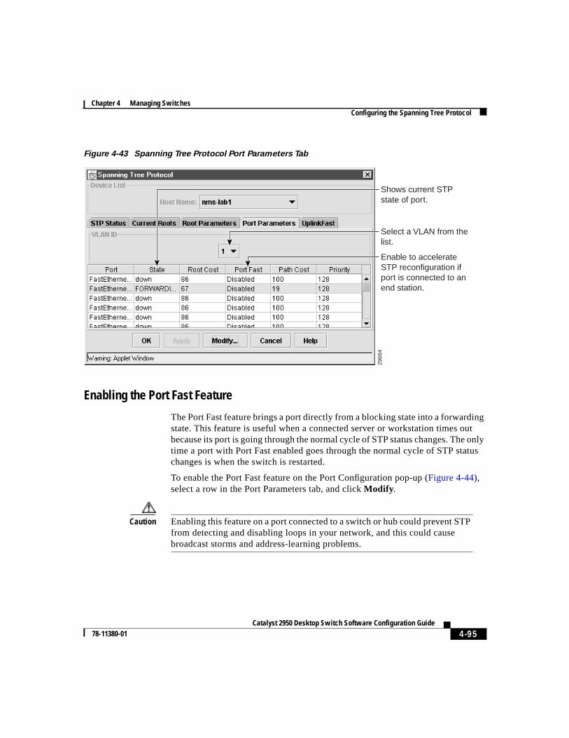
4-95Catalyst 2950 Desktop Switch Software Configuration Guide
78-11380-01
Chapter 4 Managing SwitchesConfiguring the Spanning Tree Protocol
Figure 4-43 Spanning Tree Protocol Port Parameters Tab
Enabling the Port Fast Feature
The Port Fast feature brings a port directly from a blocking state into a forwardingstate. This feature is useful when a connected server or workstation times outbecause its port is going through the normal cycle of STP status changes. The onlytime a port with Port Fast enabled goes through the normal cycle of STP statuschanges is when the switch is restarted.
To enable the Port Fast feature on the Port Configuration pop-up (Figure 4-44),select a row in the Port Parameters tab, and clickModify .
Caution Enabling this feature on a port connected to a switch or hub could prevent STPfrom detecting and disabling loops in your network, and this could causebroadcast storms and address-learning problems.
Shows current STP state of port.
Enable to accelerate STP reconfiguration if port is connected to an end station.
2966
4
Select a VLAN from the list.
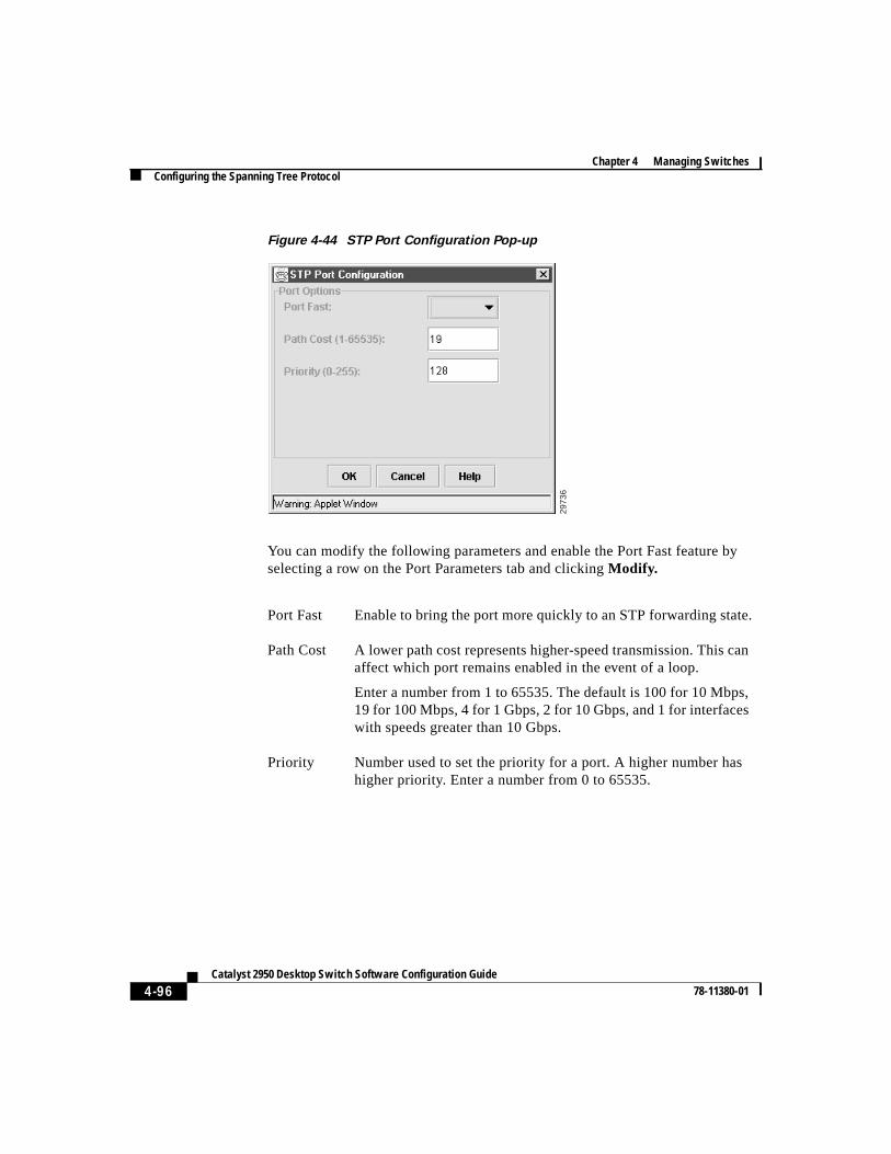
Chapter 4 Managing SwitchesConfiguring the Spanning Tree Protocol
4-96Catalyst 2950 Desktop Switch Software Configuration Guide
78-11380-01
Figure 4-44 STP Port Configuration Pop-up
You can modify the following parameters and enable the Port Fast feature byselecting a row on the Port Parameters tab and clickingModify.
2973
6
Port Fast Enable to bring the port more quickly to an STP forwarding state.
Path Cost A lower path cost represents higher-speed transmission. This canaffect which port remains enabled in the event of a loop.
Enter a number from 1 to 65535. The default is 100 for 10 Mbps,19 for 100 Mbps, 4 for 1 Gbps, 2 for 10 Gbps, and 1 for interfaceswith speeds greater than 10 Gbps.
Priority Number used to set the priority for a port. A higher number hashigher priority. Enter a number from 0 to 65535.
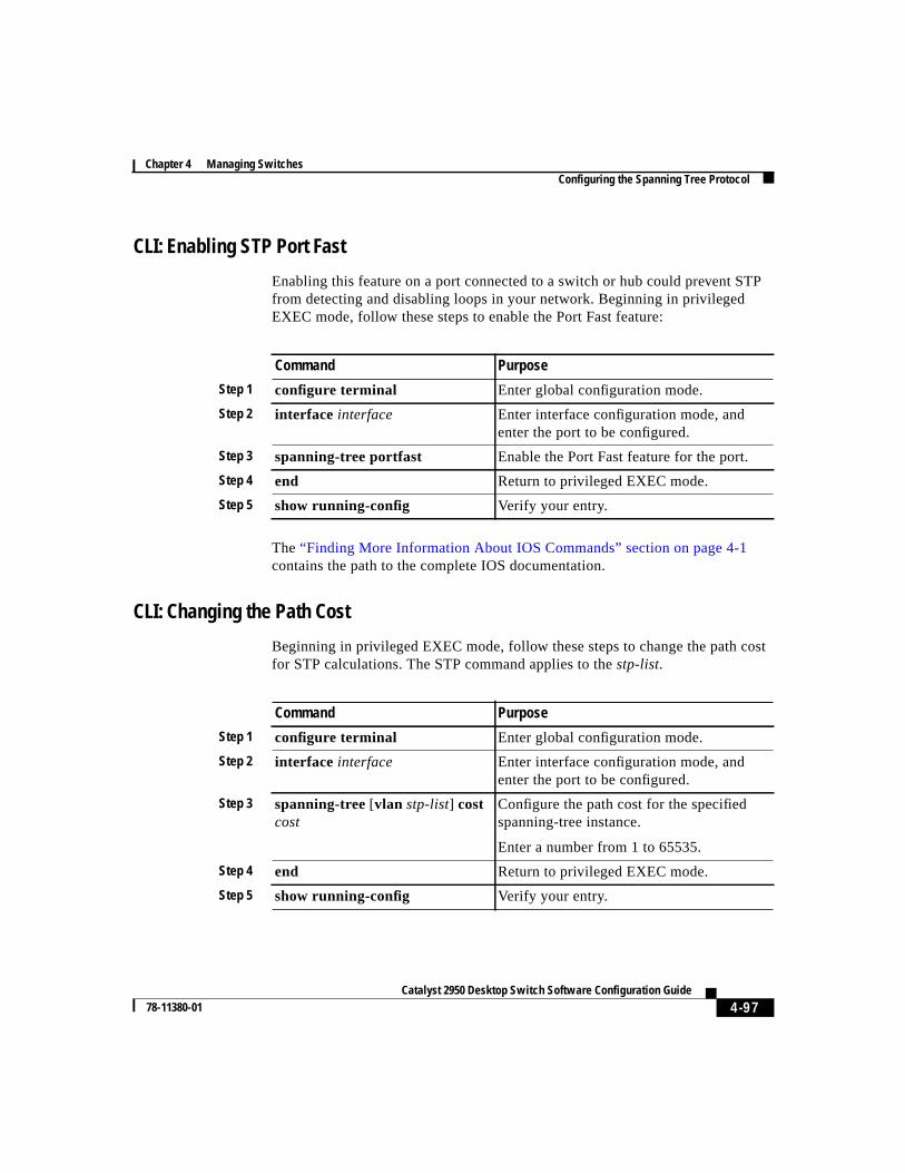
4-97Catalyst 2950 Desktop Switch Software Configuration Guide
78-11380-01
Chapter 4 Managing SwitchesConfiguring the Spanning Tree Protocol
CLI: Enabling STP Port Fast
Enabling this feature on a port connected to a switch or hub could prevent STPfrom detecting and disabling loops in your network. Beginning in privilegedEXEC mode, follow these steps to enable the Port Fast feature:
The“Finding More Information About IOS Commands” section on page 4-1contains the path to the complete IOS documentation.
CLI: Changing the Path Cost
Beginning in privileged EXEC mode, follow these steps to change the path costfor STP calculations. The STP command applies to thestp-list.
Command Purpose
Step 1 configure terminal Enter global configuration mode.
Step 2 interface interface Enter interface configuration mode, andenter the port to be configured.
Step 3 spanning-tree portfast Enable the Port Fast feature for the port.
Step 4 end Return to privileged EXEC mode.
Step 5 show running-config Verify your entry.
Command Purpose
Step 1 configure terminal Enter global configuration mode.
Step 2 interface interface Enter interface configuration mode, andenter the port to be configured.
Step 3 spanning-tree[vlan stp-list] costcost
Configure the path cost for the specifiedspanning-tree instance.
Enter a number from 1 to 65535.
Step 4 end Return to privileged EXEC mode.
Step 5 show running-config Verify your entry.
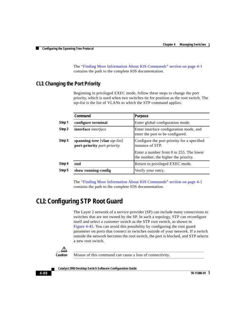
Chapter 4 Managing SwitchesConfiguring the Spanning Tree Protocol
4-98Catalyst 2950 Desktop Switch Software Configuration Guide
78-11380-01
The“Finding More Information About IOS Commands” section on page 4-1contains the path to the complete IOS documentation.
CLI: Changing the Port Priority
Beginning in privileged EXEC mode, follow these steps to change the portpriority, which is used when two switches tie for position as the root switch. Thestp-list is the list of VLANs to which the STP command applies.
The“Finding More Information About IOS Commands” section on page 4-1contains the path to the complete IOS documentation.
CLI: Configuring STP Root GuardThe Layer 2 network of a service provider (SP) can include many connections toswitches that are not owned by the SP. In such a topology, STP can reconfigureitself and select acustomer switchas the STP root switch, as shown inFigure 4-45. You can avoid this possibility by configuring the root guardparameter on ports that connect to switches outside of your network. If a switchoutside the network becomes the root switch, the port is blocked, and STP selectsa new root switch.
Caution Misuse of this command can cause a loss of connectivity.
Command Purpose
Step 1 configure terminal Enter global configuration mode.
Step 2 interface interface Enter interface configuration mode, andenter the port to be configured.
Step 3 spanning-tree[vlan stp-list]port-priority port-priority
Configure the port priority for a specifiedinstance of STP.
Enter a number from 0 to 255. The lowerthe number, the higher the priority.
Step 4 end Return to privileged EXEC mode.
Step 5 show running-config Verify your entry.
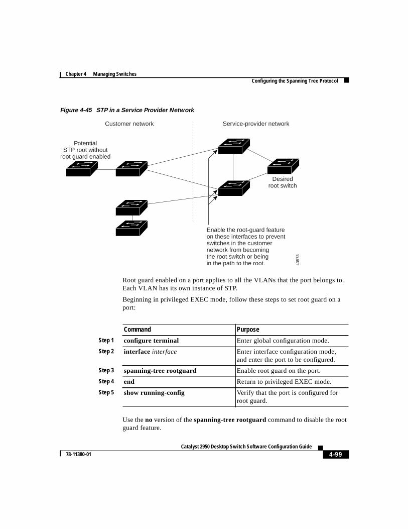
4-99Catalyst 2950 Desktop Switch Software Configuration Guide
78-11380-01
Chapter 4 Managing SwitchesConfiguring the Spanning Tree Protocol
Figure 4-45 STP in a Service Provider Network
Root guard enabled on a port applies to all the VLANs that the port belongs to.Each VLAN has its own instance of STP.
Beginning in privileged EXEC mode, follow these steps to set root guard on aport:
Use theno version of thespanning-tree rootguardcommand to disable the rootguard feature.
Customer network
PotentialSTP root without
root guard enabled
Enable the root-guard featureon these interfaces to preventswitches in the customernetwork from becomingthe root switch or beingin the path to the root.
Desiredroot switch
Service-provider network
4357
8
Command Purpose
Step 1 configure terminal Enter global configuration mode.
Step 2 interface interface Enter interface configuration mode,and enter the port to be configured.
Step 3 spanning-tree rootguard Enable root guard on the port.
Step 4 end Return to privileged EXEC mode.
Step 5 show running-config Verify that the port is configured forroot guard.
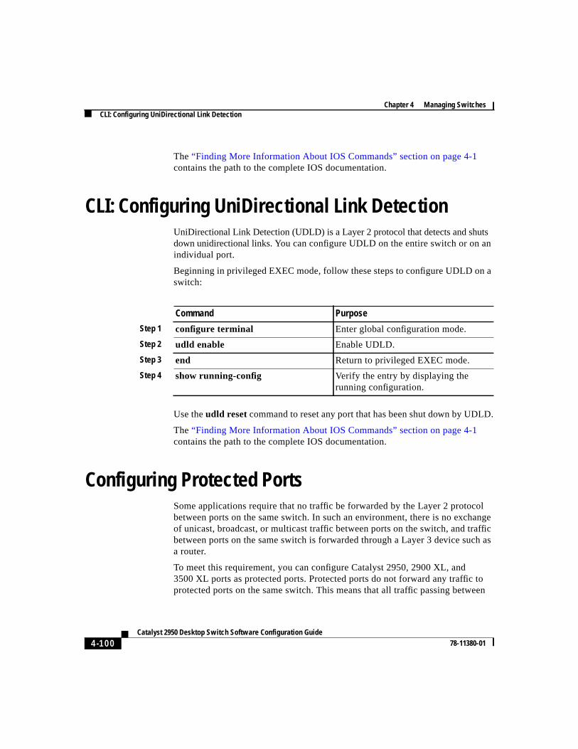
Chapter 4 Managing SwitchesCLI: Configuring UniDirectional Link Detection
4-100Catalyst 2950 Desktop Switch Software Configuration Guide
78-11380-01
The“Finding More Information About IOS Commands” section on page 4-1contains the path to the complete IOS documentation.
CLI: Configuring UniDirectional Link DetectionUniDirectional Link Detection (UDLD) is a Layer 2 protocol that detects and shutsdown unidirectional links. You canconfigure UDLD on the entire switch or on anindividual port.
Beginning in privileged EXEC mode, follow these steps to configure UDLD on aswitch:
Use theudld reset command to reset any port that has been shut down by UDLD.
The“Finding More Information About IOS Commands” section on page 4-1contains the path to the complete IOS documentation.
Configuring Protected PortsSome applications require that no traffic be forwarded by the Layer 2 protocolbetween ports on the same switch. In such an environment, there is no exchangeof unicast, broadcast, or multicast traffic between ports on the switch, and trafficbetween ports on the same switch is forwarded through a Layer 3 device such asa router.
To meet this requirement, you can configure Catalyst 2950, 2900 XL, and3500 XL ports as protected ports. Protected ports do not forward any traffic toprotected ports on the same switch. This means that all traffic passing between
Command Purpose
Step 1 configure terminal Enter global configuration mode.
Step 2 udld enable Enable UDLD.
Step 3 end Return to privileged EXEC mode.
Step 4 show running-config Verify the entry by displaying therunning configuration.
4-101Catalyst 2950 Desktop Switch Software Configuration Guide
78-11380-01
Chapter 4 Managing SwitchesConfiguring TACACS+
protected ports—unicast, broadcast, and multicast—must be forwarded through aLayer 3 device. Protected ports can forward any type of traffic to nonprotectedports, and they forward as usual to all ports on other switches.
Note There could be times when unknown unicast traffic from a nonprotected portis flooded to a protected port because a MAC address has timed out or has notbeen learned by the switch.
CLI: Configuring Protected PortsBeginning in privileged EXEC mode, follow these steps to define a port as aprotected port:
Use theno version of theport protected command to disable protected port.
The“Finding More Information About IOS Commands” section on page 4-1contains the path to the complete IOS documentation.
Configuring TACACS+The Terminal Access Controller Access Control System Plus (TACACS+)provides the means to manage network security (authentication, authorization,and accounting [AAA]) from a server. This section describes how TACACS+
Command Purpose
Step 1 configure terminal Enter global configuration mode.
Step 2 interface interface Enter interface configuration mode,and enter the port to be configured.
Step 3 port protected Enable protected port on the port.
Step 4 end Return to privileged EXEC mode.
Step 5 show port protected Verify that the port has protected portenabled.
Chapter 4 Managing SwitchesConfiguring TACACS+
4-102Catalyst 2950 Desktop Switch Software Configuration Guide
78-11380-01
works and how you can configure it. For complete syntax and usage informationfor the commands described in this chapter, refer to theCisco IOS Release 12.0 Security Command Reference.
You can only configure this feature by using the CLI; you cannot configure itthrough the Cluster Management Suite.
Understanding TACACS+In large enterprise networks, the task of administering passwords on each devicecan be simplified by centralizing user authentication on a server. TACACS+ is anaccess-control protocol that allows a switch to authenticate all login attemptsthrough a central server. The network administrator configures the switch with theaddress of the TACACS+ server, and the switch and the server exchange messagesto authenticate each user before allowing access to the management console.
TACACS+ consists of three services: authentication, authorization, andaccounting. Authentication determines who the user is and whether or not the useris allowed access to the switch. Authorization is the action of determining whatthe user is allowed to do on the system. Accounting is the action of collecting datarelated to resource usage.
CLI Procedures for Configuring TACACS+The TACACS+ feature is disabled by default. However, you can enable andconfigure it by using the CLI. You can access the CLI through the console port orthrough Telnet. To prevent a lapse in security, you cannot configure TACACS+through a network-management application. When enabled, TACACS+ canauthenticate users accessing the switch through the CLI.
Note Although the TACACS+ configuration is performed through the CLI, theTACACS+ server authenticates HTTP connections that have been configuredwith a privilege level of 15.
4-103Catalyst 2950 Desktop Switch Software Configuration Guide
78-11380-01
Chapter 4 Managing SwitchesConfiguring TACACS+
CLI: Configuring the TACACS+ Server Host
Use thetacacs-server hostcommand to specify the names of the IP host or hostsmaintaining an AAA/TACACS+ server. On TACACS+ servers, you can configurethe following additional options:
• Number of seconds that the switch attempts to contact the server before ittimes out.
• Encryption key to encrypt and decrypt all traffic between the router and thedaemon.
• Number of attempts that a user can make when entering a command that isbeing authenticated by TACACS+.
Beginning in privileged EXEC mode, follow these steps to configure theTACACS+ server:
Command Purpose
Step 1 tacacs-server hostname[timeoutinteger] [key string]
Define a TACACS+ host.
Entering thetimeout andkey parameterswith this command overrides the globalvalues that you can enter with thetacacs-server timeout(Step 3) and thetacacs-server key commands (Step 5).
Step 2 tacacs-server retransmitretries Enter the number of times the serversearches the list of TACACS+ serversbefore stopping.
The default is two.
Step 3 tacacs-server timeoutseconds Set the interval that the server waits for aTACACS+ server host to reply.
The default is 5 seconds.
Step 4 tacacs-server attempts count Set the number of login attempts that can bemade on the line.
Chapter 4 Managing SwitchesConfiguring TACACS+
4-104Catalyst 2950 Desktop Switch Software Configuration Guide
78-11380-01
The“Finding More Information About IOS Commands” section on page 4-1contains the path to the complete IOS documentation.
CLI: Configuring Login Authentication
Beginning in privileged EXEC mode, follow these steps to configure loginauthentication by using AAA/TACACS+:
Step 5 tacacs-server keykey Define a set of encryption keys for all ofTACACS+ and communication between theaccess server and the TACACS daemon.
Repeat the command for each encryptionkey.
Step 6 exit Return to privileged EXEC mode.
Step 7 show tacacs Verify your entries.
Command Purpose
Command Purpose
Step 1 configure terminal Enter global configuration mode.
Step 2 aaa new-model Enable AAA/TACACS+.
Step 3 aaa authentication login{ default | list-name} method1[method2...]
Enable authentication at login, and createone or more lists of authentication methods.
Step 4 line [aux | console | tty | vty]line-number[ending-line-number]
Enter line configuration mode, andconfigure the lines to which you want toapply the authentication list.
Step 5 login authentication {default |list-name}
Apply the authentication list to a line or setof lines.
Step 6 exit Return to privileged EXEC mode.
Step 7 show running-config Verify your entries.
4-105Catalyst 2950 Desktop Switch Software Configuration Guide
78-11380-01
Chapter 4 Managing SwitchesConfiguring TACACS+
The variablelist-name is any character string used to name the list you arecreating. Themethodvariable refers to the actual methods the authenticationalgorithm tries, in the sequence entered. You can choose one of the followingmethods:
To create a default list that is used if no list is specified in theloginauthentication command, use thedefault keyword followed by the methods youwant used in default situations.
The additional methods of authentication are used only if the previous methodreturns an error, not if it fails. To specify that the authentication succeed even ifall methods return an error, specifynoneas the final method in the command line.
The“Finding More Information About IOS Commands” section on page 4-1contains the path to the complete IOS documentation.
CLI: Specifying TACACS+ Authorization for EXEC Access and Network Services
You can use theaaa authorization command with thetacacs+ keyword to setparameters that restrict a user’s network access to Cisco IOS privilege mode(EXEC access) and to network services such as Serial Line Internet Protocol(SLIP), Point-to-Point Protocol (PPP) with Network Control Protocols (NCPs),and AppleTalk Remote Access (ARA).
line Uses the line password for authentication. You must define a linepassword before you can use this authentication method. Use thepasswordpassword line configuration mode command.
local Uses the local username database for authentication. You mustenter username information into the database. Use theusernamepassword global configuration command.
tacacs+ Uses TACACS+ authentication. You must configure the TACACS+server before you can use this authentication method. For moreinformation, see the“CLI: Configuring the TACACS+ ServerHost” section on page 4-102.
Chapter 4 Managing SwitchesConfiguring TACACS+
4-106Catalyst 2950 Desktop Switch Software Configuration Guide
78-11380-01
The aaa authorization exec tacacs+ localcommand sets the followingauthorization parameters:
• Use TACACS+ for EXEC access authorization if authentication was doneusing TACACS+.
• Use the local database if authentication was not done using TACACS+.
Note Authorization is bypassed for authenticated users who login through the CLIeven if authorization has been configured.
Beginning in privileged EXEC mode, follow these steps to specify TACACS+authorization for EXEC access and network services:
The“Finding More Information About IOS Commands” section on page 4-1contains the path to the complete IOS documentation.
CLI: Starting TACACS+ Accounting
You use theaaa accounting command with thetacacs+ keyword to turn onTACACS+ accounting for each Cisco IOS privilege level and for networkservices.
Command Purpose
Step 1 configure terminal Enter global configuration mode.
Step 2 aaa authorization networktacacs+
Configure the switch for user TACACS+authorization for all network-relatedservice requests, including SLIP, PPPNCPs, and ARA protocols.
Step 3 aaa authorization exec tacacs+ Configure the switch for user TACACS+authorization to determine if the user isallowed EXEC access.
Theexeckeyword might return user profileinformation (such asautocommandinformation).
Step 4 exit Return to privileged EXEC mode.
4-107Catalyst 2950 Desktop Switch Software Configuration Guide
78-11380-01
Chapter 4 Managing SwitchesConfiguring TACACS+
Beginning in privileged EXEC mode, follow these steps to enable TACACS+accounting:
Note These commands are documented in the “Accounting and Billing Commands”chapter of theCisco IOS Release 12.0 Security Command Reference.
CLI: Configuring a Switch for Local AAA
You can configure AAA to operate without a server by setting the switch toimplement AAA in local mode. Authentication and authorization are then handledby the switch. No accounting is available in this configuration.
Beginning in privileged EXEC mode, follow these steps to configure the switchfor local AAA:
Command Purpose
Step 1 configure terminal Enter global configuration mode.
Step 2 aaa accounting exec start-stoptacacs+
Enable TACACS+ accounting to send astart-record accounting notice at thebeginning of an EXEC process and astop-record at the end.
Step 3 aaa accounting networkstart-stop tacacs+
Enable TACACS+ accounting for allnetwork-related service requests, includingSLIP, PPP, and PPP NCPs.
Step 4 exit Return to privileged EXEC mode.
Command Purpose
Step 1 configure terminal Enter global configuration mode.
Step 2 aaa new-model Enable AAA.
Step 3 aaa authentication login defaultlocal
Set the login authorization to default tolocal.
Chapter 4 Managing SwitchesConfiguring the Switch for Remote Monitoring
4-108Catalyst 2950 Desktop Switch Software Configuration Guide
78-11380-01
The“Finding More Information About IOS Commands” section on page 4-1contains the path to the complete IOS documentation.
Configuring the Switch for Remote MonitoringYou can use the Remote Monitoring (RMON) feature with the SNMP agent in theswitch to monitor all the traffic flowing among switches on all connected LANsegments.
You can configure your switch for RMON, which is disabled by default, by usingthe CLI or an SNMP-compatible network management station. You cannotconfigure it by using VSM. In addition, a generic RMON console application isrecommended on the CMS to take advantage of RMON's network managementcapabilities. You must also configure SNMP on the switch to access RMON MIBobjects.
RMON data is usually placed in the high-priority queue for the processor and canrender the switch unusable; however, because the 2950 switches use hardwarecounters, the monitoring is more efficient and little processing power is required.
The switch supports the following four RMON groups:
• Alarms—Monitor a specific MIB object for a specified interval, trigger analarm at a specified value (rising threshold), and reset the alarm at anothervalue (falling threshold). Alarms can be used with events; the alarm triggersan event, which can generate a log entry or an SNMP trap.
• Events—Determine the action to take when an event is triggered by an alarm.The action can be to generate a log entry or an SNMP trap.
Step 4 aaa authorization exec local Configure user AAA authorization for allnetwork-related service requests, includingSLIP, PPP NCPs, and ARA protocols.
Step 5 aaa authorization network local Configure user AAA authorization todetermine if the user is allowed to run anEXEC shell.
Step 6 usernamenamepasswordpasswordprivilege level
Enter the local database.
Repeat this command for each user.
Command Purpose
4-109Catalyst 2950 Desktop Switch Software Configuration Guide
78-11380-01
Chapter 4 Managing SwitchesConfiguring the Switch for Remote Monitoring
• History—Collect a history group of statistics on an interface for a specifiedpolling interval.
• Statistics—Collect Ethernet statistics on an interface.
You configure RMON alarms and events in global configuration mode by usingthe rmon alarms andrmon events commands. You can collect group history orgroup Ethernet statistics in the interface configuration mode by using the rmoncollection history or rmon collection stats commands.
This guide describes the use of IOS commands that have been created or changedfor switches that support IOS Release 12.0(5)WC(1). For information on otherIOS Release 12.0 commands, refer to the Cisco IOS Release 12.0 documentationset available on Cisco.com.

Chapter 4 Managing SwitchesConfiguring the Switch for Remote Monitoring
4-110Catalyst 2950 Desktop Switch Software Configuration Guide
78-11380-01