Embed Size (px)
Citation preview
Features• 182 USt capacity
• 5510 ft-kips maximum load moment
• 275 ft main boom
• Max boom + fixed jib combination: 226 ft + 80 ft
• Max boom + luffing jib combination: 167 ft + 170 ft
• 320 hp Tier IVi engine
• 300 hp Tier III engine
Manitowoc MLC165Product GuideASME B30.5Imperial

Contents
3Manitowoc MLC165
Specifications 4
Outline dimensions 7
Transport data 13
Performance data 14
Boom combinations 18
Main boom range / load charts 21
Fixed jib range / load charts 23
Luffing jib range / load charts 26
Manitowoc Crane Care 30
Specifications
4
Replaceable, ten micron (absolute) full flow tank filter is furnished in the hydraulic circuit. All oil is filtered prior to return to the hydraulic reservoir.
Hydraulic system also includes hydraulic oil cooler.
Drums
Two equal width winches are driven by independent variable displacement axial piston hydraulic motors through planetary reduction. Drums are grooved for 26 mm rope.
Powered hoisting/lowering operation is standard with automatic (spring applied, hydraulically released) multi-disc brakes, and drum rotation indicators.
Optional: free-fall operation for front and/or rear drums.
Optional: auxiliary (third) hydraulic powered drum mounted in boom butt. Includes third drum control system. Auxiliary drum may be used as the luffing hoist when machine is equipped with a luffing jib.
Optional: auxiliary drum preparation includes electric wiring, controls, hydraulic selector valve and plumbing.
Boom hoist
Independent boom hoist consists of a single drum grooved for 22 mm diameter wire rope. Includes 22 mm diameter wire rope for 20 part line reeving.
Drum is powered by a fixed displacement hydraulic motor coupled to an internal brake and planetary gearbox equipped with ratchet and pawl.
Mast
Moving mast is 23' 7" long and connects the boom hoist reeving to the steel boom suspension pendant rigging. When used with optional self-erect package, the mast is utilized for crane assembly and disassembly. The mast is capable of lifting and positioning the crawler assemblies, stacking the counterweights and assembling the boom and jib, utilizing the self assembly cylinder.
Rotating bed includes counterweight raising cylinders capable of lifting the entire upperworks counterweight for removal and installation. The upperworks counterweight is attached to rotating bed with power-actuated pins.
Upperworks
Engine
Cummins Model QSL9-300 Tier III, 6 cylinder, 300 hp at 2100 governed RPM.
Cummins Model QSL9-320 Tier IVi, 6 cylinder, 320 hp at 2100 governed RPM.
Includes engine block heater (120 V), air heater starting aid (24 V), oil heater starting aid (120 V), high silencing muffler (Tier III) or diesel particulate filter (Tier IVi), radiator and fan.
24 volt starting and 70 amp alternator.
One 150 gallon capacity diesel fuel tank, mounted on right side of upperworks with sight and electrical level indicator.
Controls
Hydraulic pilot controls provide infinite speed response directly proportional to control lever movement. Controls include Manitowoc’s CANBUS operating system providing microprocessor driven control logic, pump control, on-board diagnostics and service information.
Block-up limit control is standard for hoist and whip lines.
RCL/RCI (Rated Capacity Limiter/Rated Capacity Indicator) system is standard for main boom and upper boom point. “Function cut-out” or “warning only” operation is available via programmable configuration.
Travel and swing alarms are standard.
Hydraulic system
Three high-pressure pumps are driven by the engine. Two pumps provide hydraulic power enabling simultaneous multi-function capability. One pump provides independent "closed loop" hydraulic power for the swing system. An additional fourth pump is required for free fall.
Hydraulic reservoir capacity is 158 gallon and is equipped with breather, sight and electrical level indicator, clean out access, and internal diffuser.
Each function is equipped with relief valves to protect the hydraulic circuit from overload or shock.
Specifications
5Manitowoc MLC165
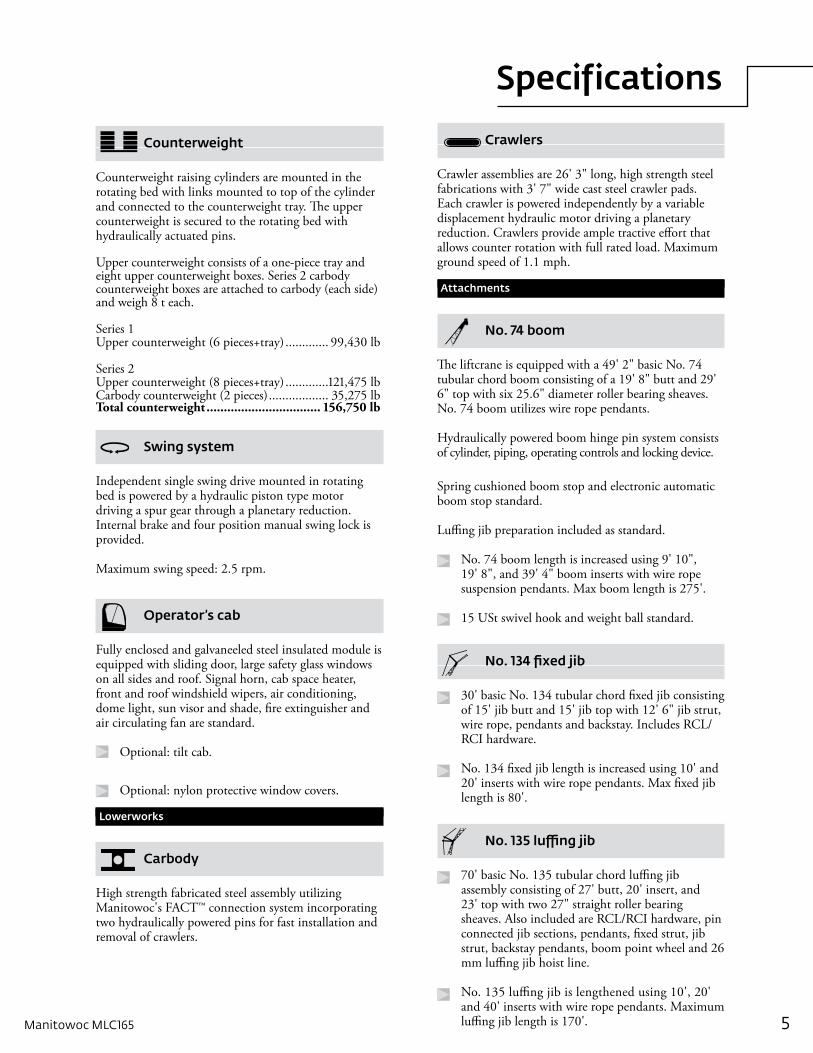
Counterweight
Counterweight raising cylinders are mounted in the rotating bed with links mounted to top of the cylinder and connected to the counterweight tray. The upper counterweight is secured to the rotating bed with hydraulically actuated pins.
Upper counterweight consists of a one-piece tray and eight upper counterweight boxes. Series 2 carbody counterweight boxes are attached to carbody (each side) and weigh 8 t each.
Series 1Upper counterweight (6 pieces+tray) ............. 99,430 lb
Series 2Upper counterweight (8 pieces+tray) .............121,475 lbCarbody counterweight (2 pieces) .................. 35,275 lbTotal counterweight ................................. 156,750 lb
Swing system
Independent single swing drive mounted in rotating bed is powered by a hydraulic piston type motor driving a spur gear through a planetary reduction. Internal brake and four position manual swing lock is provided.
Maximum swing speed: 2.5 rpm.
Operator’s cab
Fully enclosed and galvaneeled steel insulated module is equipped with sliding door, large safety glass windows on all sides and roof. Signal horn, cab space heater, front and roof windshield wipers, air conditioning, dome light, sun visor and shade, fire extinguisher and air circulating fan are standard.
Optional: tilt cab.
Optional: nylon protective window covers.
Lowerworks
Carbody
High strength fabricated steel assembly utilizing Manitowoc's FACT™ connection system incorporating two hydraulically powered pins for fast installation and removal of crawlers.
Crawlers
Crawler assemblies are 26' 3" long, high strength steel fabrications with 3' 7" wide cast steel crawler pads. Each crawler is powered independently by a variable displacement hydraulic motor driving a planetary reduction. Crawlers provide ample tractive effort that allows counter rotation with full rated load. Maximum ground speed of 1.1 mph.
Attachments
No. 74 boom
The liftcrane is equipped with a 49' 2" basic No. 74 tubular chord boom consisting of a 19' 8" butt and 29' 6" top with six 25.6" diameter roller bearing sheaves. No. 74 boom utilizes wire rope pendants.
Hydraulically powered boom hinge pin system consists of cylinder, piping, operating controls and locking device.
Spring cushioned boom stop and electronic automatic boom stop standard.
Luffing jib preparation included as standard.
No. 74 boom length is increased using 9' 10", 19' 8", and 39' 4" boom inserts with wire rope suspension pendants. Max boom length is 275'.
15 USt swivel hook and weight ball standard.
No. 134 fixed jib
30' basic No. 134 tubular chord fixed jib consisting of 15' jib butt and 15' jib top with 12' 6" jib strut, wire rope, pendants and backstay. Includes RCL/RCI hardware.
No. 134 fixed jib length is increased using 10' and 20' inserts with wire rope pendants. Max fixed jib length is 80'.
No. 135 luffing jib
70' basic No. 135 tubular chord luffing jib assembly consisting of 27' butt, 20' insert, and 23' top with two 27" straight roller bearing sheaves. Also included are RCL/RCI hardware, pin connected jib sections, pendants, fixed strut, jib strut, backstay pendants, boom point wheel and 26 mm luffing jib hoist line.
No. 135 luffing jib is lengthened using 10', 20' and 40' inserts with wire rope pendants. Maximum luffing jib length is 170'.
Specifications
6
Optional equipment
Self-erect system includes: carbody jacking cylinders with pads, controls, self assembly cylinder, boom-butt installation support, counterweight cylinders and crawler handling chain.
Detachable upper boom point with one 30" diameter tapered roller bearing sheave for No. 74 boom top (this is same upper boom point used on 555, 777, 999, 2250,16000 and 18000).
Blocks and hooks – 30 USt hook block with one 30" sheave for 26
mm wire rope with swivel hook, hook latch and swivel lock.
60 USt hook block with two 30" sheaves for 26
mm wire rope with swivel hook, hook latch and swivel lock.
100 USt hook block with three 30" sheaves for 26 mm wire rope with swivel hook, hook latch, and swivel lock.
165 USt hook block with five 30" sheaves for 26 mm wire rope with single barb swivel hook, hook latch, and swivel lock.
165 USt hook block with five 30" sheaves for 26 mm wire rope with duplex swivel hook, hook latch, and swivel lock.
Hydraulic Test Kit.
Service Interval Kits.
Special Paint Color (other than Manitowoc standard red and black.)
Zinc rich primer (marine applications) for corrosion resistance.
Special Customer Decals: custom vinyl decal(s) of name and/or logo from artwork supplied by customer.
Export Packaging: basic crane, boom and jib sections.
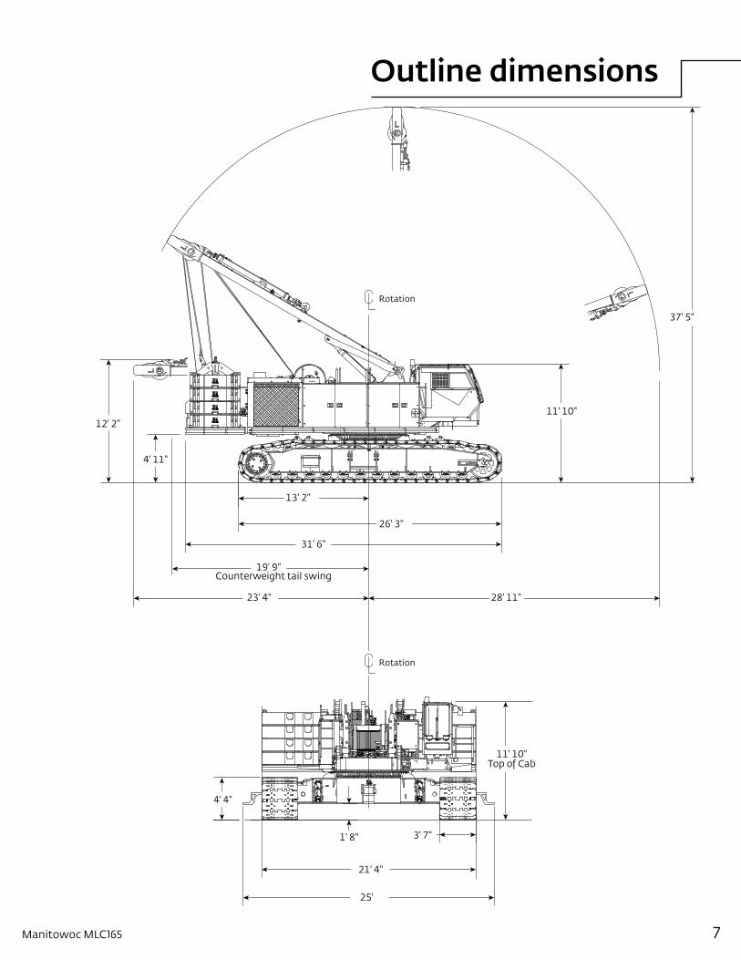
Outline dimensions
7Manitowoc MLC165
Rotation
Rotation
Counterweight tail swing
37' 5"
28' 11"
11' 10"
26' 3"
13' 2"
31' 6"
19' 9"
23' 4"
4' 11"
12' 2"
4' 4"
1' 8"
21' 4"
25'
3' 7"
11' 10"Top of Cab
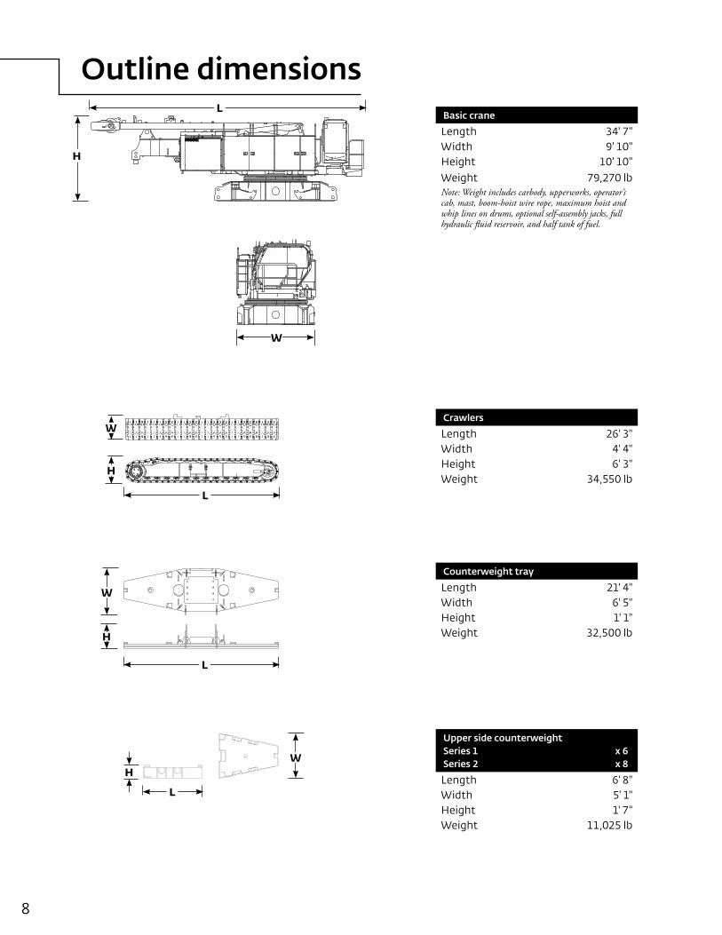
Outline dimensions
8
Basic crane
Length 34' 7"Width 9' 10"Height 10' 10"Weight 79,270 lbNote: Weight includes carbody, upperworks, operator’s cab, mast, boom-hoist wire rope, maximum hoist and whip lines on drums, optional self-assembly jacks, full hydraulic fluid reservoir, and half tank of fuel.
Crawlers
Length 26' 3"Width 4' 4"Height 6' 3"Weight 34,550 lb
Counterweight tray
Length 21' 4"Width 6' 5"Height 1' 1"Weight 32,500 lb
Upper side counterweight Series 1 x 6 Series 2 x 8
Length 6' 8"Width 5' 1"Height 1' 7"Weight 11,025 lb
L
H
W
L
H
W
L
H
W
WH
L
Outline dimensions
9Manitowoc MLC165
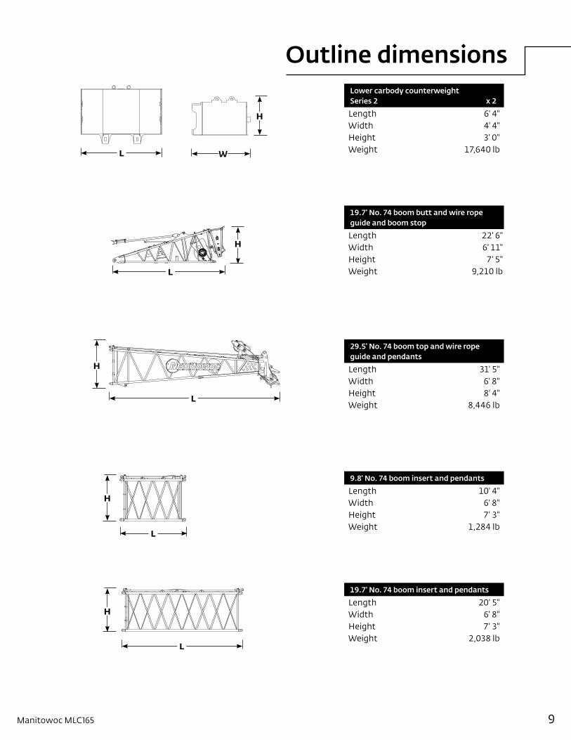
Lower carbody counterweight Series 2 x 2
Length 6' 4"Width 4' 4"Height 3' 0"Weight 17,640 lb
19.7' No. 74 boom butt and wire rope guide and boom stop
Length 22' 6"Width 6' 11"Height 7' 5"Weight 9,210 lb
29.5' No. 74 boom top and wire rope guide and pendants
Length 31' 5"Width 6' 8"Height 8' 4"Weight 8,446 lb
9.8' No. 74 boom insert and pendants
Length 10' 4"Width 6' 8"Height 7' 3"Weight 1,284 lb
19.7' No. 74 boom insert and pendants
Length 20' 5"Width 6' 8"Height 7' 3"Weight 2,038 lb
L W
H
L
H
L
H
L
H
L
H
Outline dimensions
10
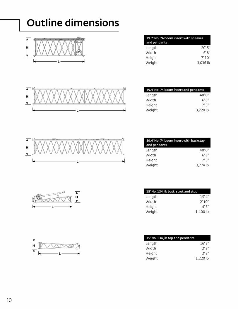
19.7' No. 74 boom insert with sheaves and pendants
Length 20' 5"Width 6' 8"Height 7' 10"Weight 3,036 lb
39.4' No. 74 boom insert and pendants
Length 40' 0"Width 6' 8"Height 7' 3"Weight 3,720 lb
39.4' No. 74 boom insert with backstay and pendants
Length 40' 0"Width 6' 8"Height 7' 3"Weight 3,774 lb
15' No. 134 jib butt, strut and stop
Length 15' 4"Width 2' 10"Height 4' 3"Weight 1,400 lb
15' No. 134 jib top and pendants
Length 16' 3"Width 2' 8"Height 2' 8"Weight 1,220 lb
H
L
L
H
L
H
L
H
L
H
Outline dimensions
11Manitowoc MLC165
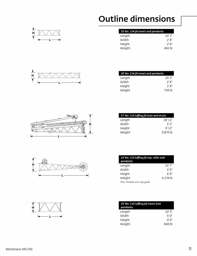
10' No. 134 jib insert and pendants
Length 10' 3"Width 2' 8"Height 2' 8"Weight 482 lb
20' No. 134 jib insert and pendants
Length 20' 3"Width 2' 8"Height 2' 8"Weight 750 lb
27' No. 135 luffing jib butt and struts
Length 28' 11"Width 5' 2"Height 9' 11"Weight 9,870 lb
23' No. 135 luffing jib top, roller and pendants
Length 25' 7"Width 5' 0"Height 6' 8"Weight 4,374 lbNote: Includes wire rope guide.
10' No. 135 luffing jib insert and pendants
Length 10' 4"Width 5' 0"Height 4' 4"Weight 840 lb
L
H
L
H
L
H
L
H
L
H
Outline dimensions
12
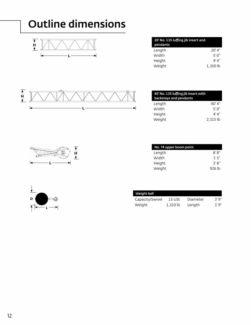
Weight ball
Capacity/Swivel 15 USt Diameter 3' 9"Weight 1,310 lb Length 1' 9"
20' No. 135 luffing jib insert and pendants
Length 20' 4"Width 5' 0"Height 4' 4"Weight 1,350 lb
40' No. 135 luffing jib insert with backstays and pendants
Length 40' 4"Width 5' 0"Height 4' 4"Weight 2,315 lb
No. 74 upper boom point
Length 8' 8"Width 1' 5"Height 2' 8"Weight 926 lb
D
L
L
H
L
H
L
H
Transport data
13Manitowoc MLC165
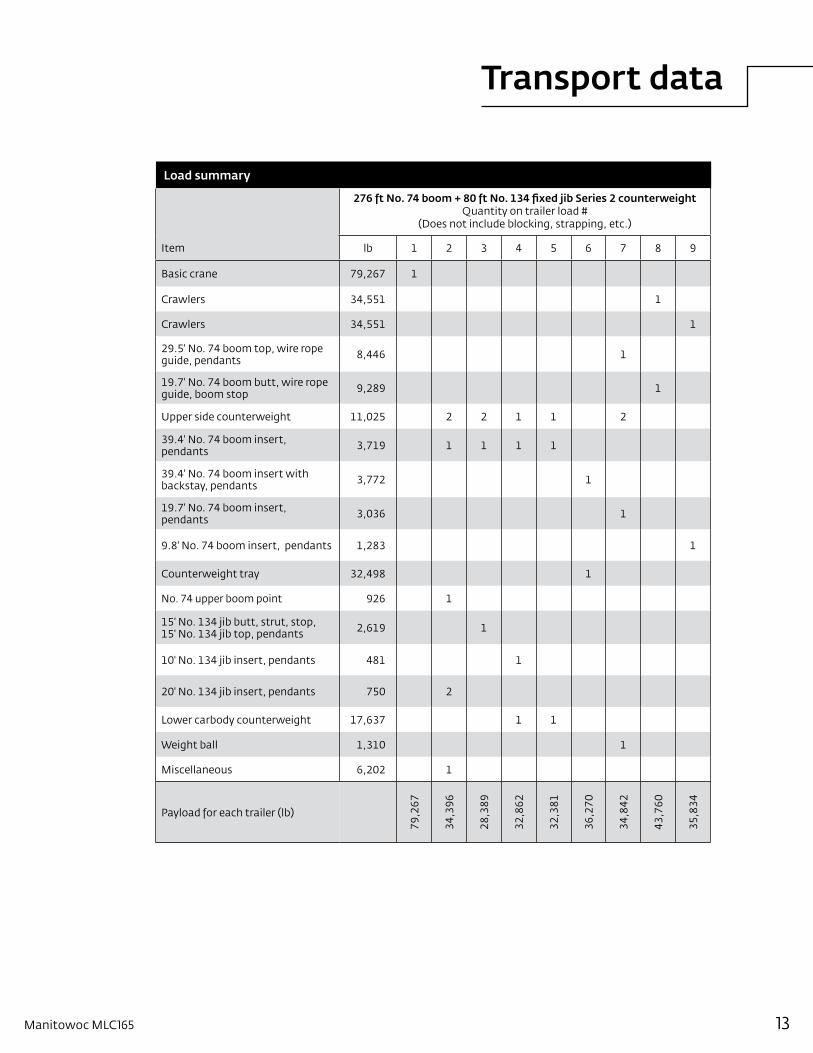
Load summary
276 ft No. 74 boom + 80 ft No. 134 fixed jib Series 2 counterweightQuantity on trailer load #
(Does not include blocking, strapping, etc.)
Item lb 1 2 3 4 5 6 7 8 9
Basic crane 79,267 1
Crawlers 34,551 1
Crawlers 34,551 1
29.5' No. 74 boom top, wire rope guide, pendants 8,446 1
19.7' No. 74 boom butt, wire rope guide, boom stop 9,289 1
Upper side counterweight 11,025 2 2 1 1 2
39.4' No. 74 boom insert, pendants 3,719 1 1 1 1
39.4' No. 74 boom insert with backstay, pendants 3,772 1
19.7' No. 74 boom insert, pendants 3,036 1
9.8' No. 74 boom insert, pendants 1,283 1
Counterweight tray 32,498 1
No. 74 upper boom point 926 1
15' No. 134 jib butt, strut, stop, 15' No. 134 jib top, pendants 2,619 1
10' No. 134 jib insert, pendants 481 1
20' No. 134 jib insert, pendants 750 2
Lower carbody counterweight 17,637 1 1
Weight ball 1,310 1
Miscellaneous 6,202 1
Payload for each trailer (lb)
79,2
67
34,3
96
28,3
89
32,8
62
32,3
81
36,2
70
34,8
42
43,7
60
35,8
34
Performance data
14
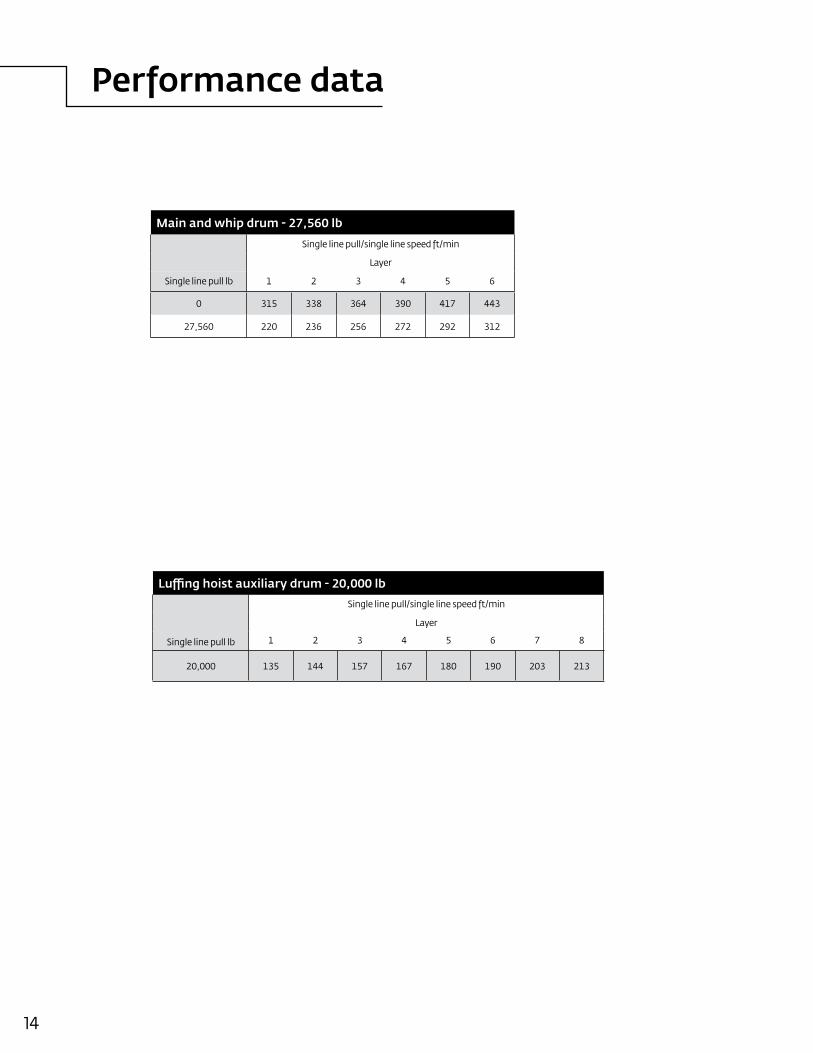
Main and whip drum - 27,560 lb
Single line pull/single line speed ft/min
Layer
Single line pull lb 1 2 3 4 5 6
0 315 338 364 390 417 443
27,560 220 236 256 272 292 312
Luffing hoist auxiliary drum - 20,000 lb
Single line pull lb
Single line pull/single line speed ft/min
Layer
1 2 3 4 5 6 7 8
20,000 135 144 157 167 180 190 203 213
Performance data
15Manitowoc MLC165
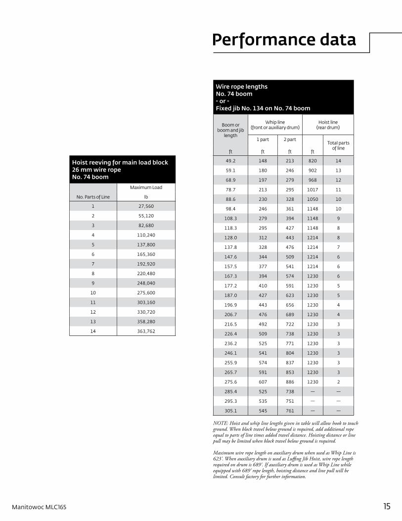
Hoist reeving for main load block 26 mm wire rope No. 74 boom
No. Parts of Line
Maximum Load
lb
1 27,560
2 55,120
3 82,680
4 110,240
5 137,800
6 165,360
7 192,920
8 220,480
9 248,040
10 275,600
11 303,160
12 330,720
13 358,280
14 363,762
Wire rope lengths No. 74 boom - or - Fixed jib No. 134 on No. 74 boom
Boom or boom and jib
length
Whip line (front or auxiliary drum)
Hoist line (rear drum)
1 part 2 partTotal parts
of lineft ft ft ft
49.2 148 213 820 14
59.1 180 246 902 13
68.9 197 279 968 12
78.7 213 295 1017 11
88.6 230 328 1050 10
98.4 246 361 1148 10
108.3 279 394 1148 9
118.3 295 427 1148 8
128.0 312 443 1214 8
137.8 328 476 1214 7
147.6 344 509 1214 6
157.5 377 541 1214 6
167.3 394 574 1230 6
177.2 410 591 1230 5
187.0 427 623 1230 5
196.9 443 656 1230 4
206.7 476 689 1230 4
216.5 492 722 1230 3
226.4 509 738 1230 3
236.2 525 771 1230 3
246.1 541 804 1230 3
255.9 574 837 1230 3
265.7 591 853 1230 3
275.6 607 886 1230 2
285.4 525 738 — —
295.3 535 751 — —
305.1 545 761 — —
NOTE: Hoist and whip line lengths given in table will allow hook to touch ground. When block travel below ground is required, add additional rope equal to parts of line times added travel distance. Hoisting distance or line pull may be limited when block travel below ground is required.
Maximum wire rope length on auxiliary drum when used as Whip Line is 623'. When auxiliary drum is used as Luffing Jib Hoist, wire rope length required on drum is 689'. If auxiliary drum is used as Whip Line while equipped with 689' rope length, hoisting distance and line pull will be limited. Consult factory for further information.
Performance data
16
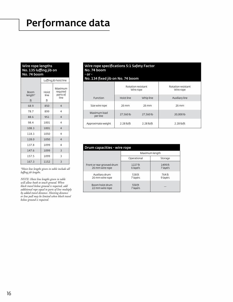
Wire rope lengths No. 135 luffing jib on No. 74 boom
Luffing jib hoist line
Boom length*
Hoist line
Maximum required parts of
lineft ft
68.9 850 4
78.7 899 4
88.6 951 4
98.4 1001 4
108.3 1001 4
118.3 1050 4
128.0 1050 4
137.8 1099 4
147.6 1099 3
157.5 1099 3
167.3 1152 3
*Hoist line lengths given in table include all luffing jib lengths.
NOTE: Hoist line lengths given in table will allow hook to touch ground. When block travel below ground is required, add additional rope equal to parts of line multiply by added travel distance. Hoisting distance or line pull may be limited when block travel below ground is required.
Wire rope specifications 5:1 Safety Factor No. 74 boom - or - No. 134 fixed jib on No. 74 boom
Rotation resistantWire rope
Rotation resistant Wire rope
Function Hoist line Whip line Auxiliary line
Size wire rope 26 mm 26 mm 26 mm
Maximum load per line 27,560 lb 27,560 lb 20,000 lb
Approximate weight 2.28 lb/ft 2.28 lb/ft 2.28 lb/ft
Drum capacities - wire ropeMaximum length
Operational Storage
Front or rear grooved drum 26 mm wire rope
1227 ft 6 layers
1499 ft7 layers
Auxiliary drum 26 mm wire rope
538 ft7 layers
764 ft9 layers
Boom hoist drum 22 mm wire rope
558 ft 7 layers —
Performance data
17Manitowoc MLC165
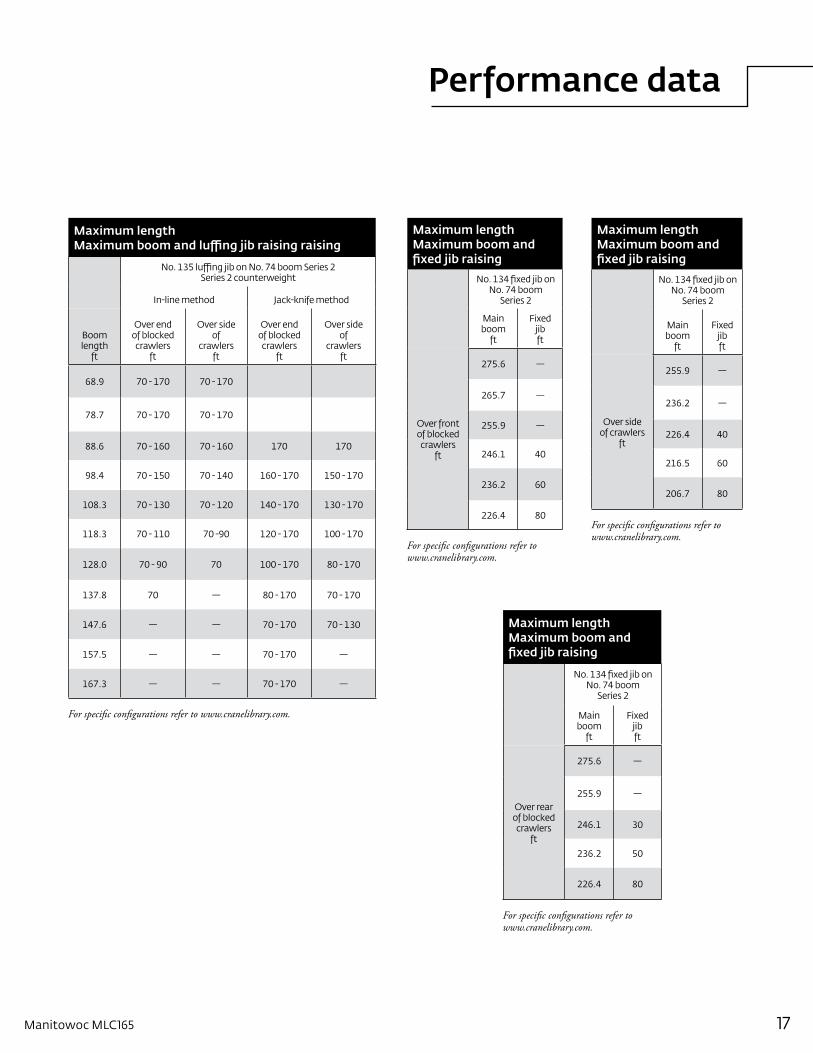
Maximum length Maximum boom and fixed jib raising
No. 134 fixed jib on No. 74 boom
Series 2
Main boom
ft
Fixed jibft
Over front of blocked crawlers
ft
275.6 —
265.7 —
255.9 —
246.1 40
236.2 60
226.4 80
For specific configurations refer to www.cranelibrary.com.
Maximum length Maximum boom and fixed jib raising
No. 134 fixed jib on No. 74 boom
Series 2
Main boom
ft
Fixed jibft
Over rear of blocked crawlers
ft
275.6 —
255.9 —
246.1 30
236.2 50
226.4 80
For specific configurations refer to www.cranelibrary.com.
Maximum length Maximum boom and fixed jib raising
No. 134 fixed jib on No. 74 boom
Series 2
Main boom
ft
Fixed jibft
Over side of crawlers
ft
255.9 —
236.2 —
226.4 40
216.5 60
206.7 80
For specific configurations refer to www.cranelibrary.com.
Maximum lengthMaximum boom and luffing jib raising raising
No. 135 luffing jib on No. 74 boom Series 2Series 2 counterweight
In-line method Jack-knife method
Boom length
ft
Over end of blocked crawlers
ft
Over side of
crawlersft
Over end of blocked crawlers
ft
Over side of
crawlersft
68.9 70 - 170 70 - 170
78.7 70 - 170 70 - 170
88.6 70 - 160 70 - 160 170 170
98.4 70 - 150 70 - 140 160 - 170 150 - 170
108.3 70 - 130 70 - 120 140 - 170 130 - 170
118.3 70 - 110 70 -90 120 - 170 100 - 170
128.0 70 - 90 70 100 - 170 80 - 170
137.8 70 — 80 - 170 70 - 170
147.6 — — 70 - 170 70 - 130
157.5 — — 70 - 170 —
167.3 — — 70 - 170 —
For specific configurations refer to www.cranelibrary.com.
Boom combinations
18
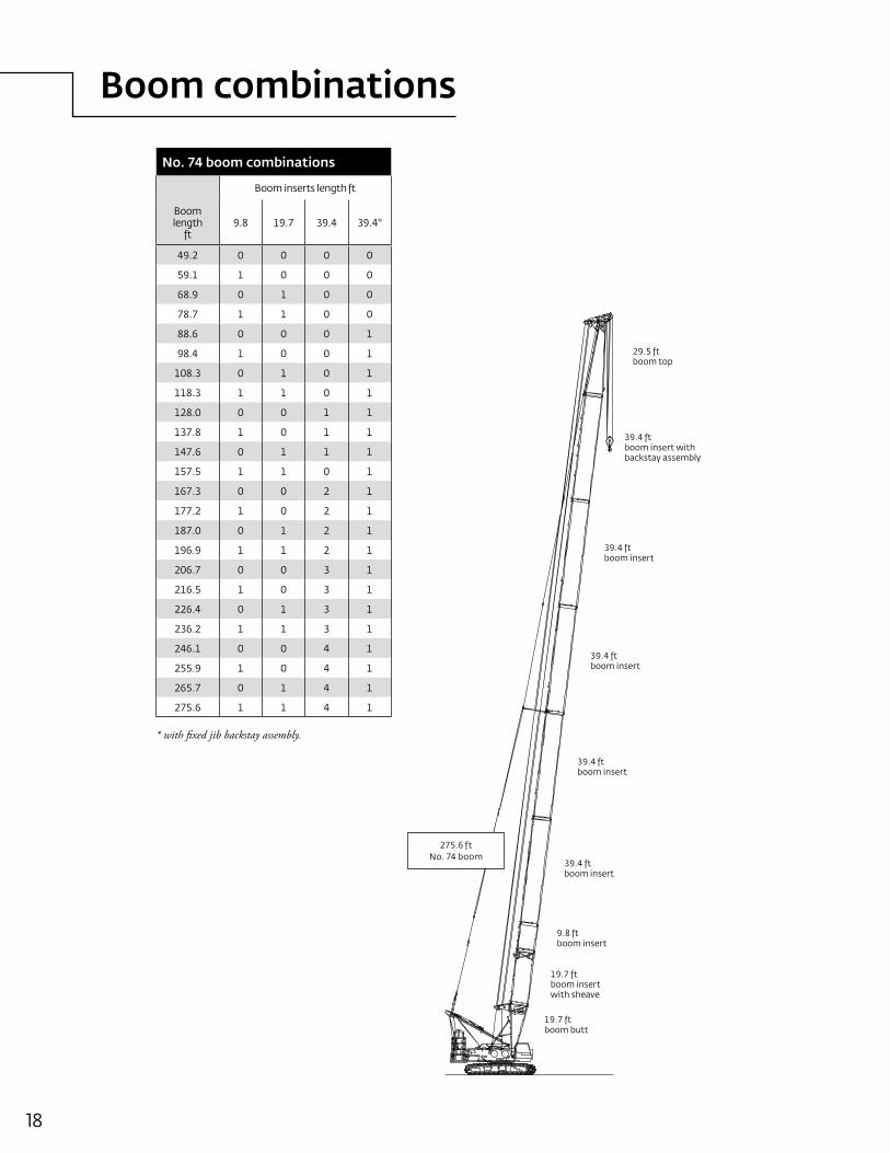
No. 74 boom combinations
Boom inserts length ft
Boomlength
ft9.8 19.7 39.4 39.4*
49.2 0 0 0 0
59.1 1 0 0 0
68.9 0 1 0 0
78.7 1 1 0 0
88.6 0 0 0 1
98.4 1 0 0 1
108.3 0 1 0 1
118.3 1 1 0 1
128.0 0 0 1 1
137.8 1 0 1 1
147.6 0 1 1 1
157.5 1 1 0 1
167.3 0 0 2 1
177.2 1 0 2 1
187.0 0 1 2 1
196.9 1 1 2 1
206.7 0 0 3 1
216.5 1 0 3 1
226.4 0 1 3 1
236.2 1 1 3 1
246.1 0 0 4 1
255.9 1 0 4 1
265.7 0 1 4 1
275.6 1 1 4 1
* with fixed jib backstay assembly.
9.8 ftboom insert
29.5 ftboom top
19.7 ftboom butt
39.4 ftboom insert
275.6 ftNo. 74 boom
19.7 ftboom insert with sheave
39.4 ftboom insert
39.4 ftboom insert
39.4 ftboom insert
39.4 ftboom insert with backstay assembly
Boom combinations
19Manitowoc MLC165
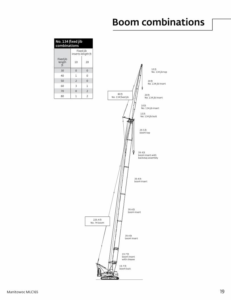
No. 134 fixed jib combinations
Fixed jib inserts length ft
Fixed jiblength
ft10 20
30 0 0
40 1 0
50 2 0
60 3 1
70 0 2
80 1 2
19.7 ftboom butt
226.4 ftNo. 74 boom
19.7 ftboom insert with sheave
39.4 ftboom insert
80 ftNo. 134 fixed jib
10 ftNo. 134 jib insert
39.4 ftboom insert
39.4 ftboom insert
15 ftNo. 134 jib butt
39.4 ftboom insert with backstay assembly
29.5 ftboom top
20 ftNo. 134 jib insert
15 ftNo. 134 jib top
20 ftNo. 134 jib insert
Boom combinations
20
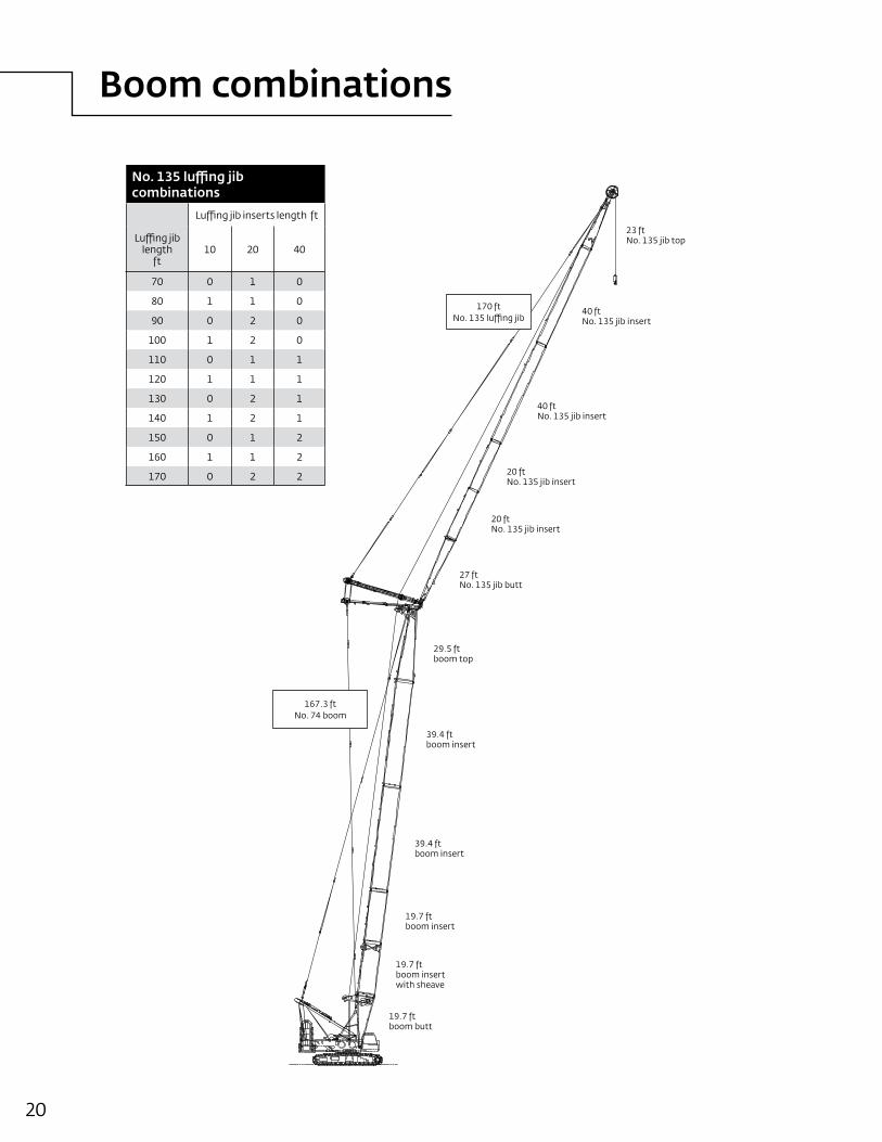
No. 135 luffing jib combinations
Luffing jib inserts length ft
Luffing jiblength
ft 10 20 40
70 0 1 0
80 1 1 0
90 0 2 0
100 1 2 0
110 0 1 1
120 1 1 1
130 0 2 1
140 1 2 1
150 0 1 2
160 1 1 2
170 0 2 2
23 ftNo. 135 jib top
19.7 ftboom butt
167.3 ftNo. 74 boom
19.7 ftboom insert with sheave
40 ftNo. 135 jib insert
29.5 ftboom top
170 ftNo. 135 luffing jib
20 ftNo. 135 jib insert
20 ftNo. 135 jib insert
39.4 ftboom insert
39.4 ftboom insert
19.7 ftboom insert
27 ftNo. 135 jib butt
40 ftNo. 135 jib insert
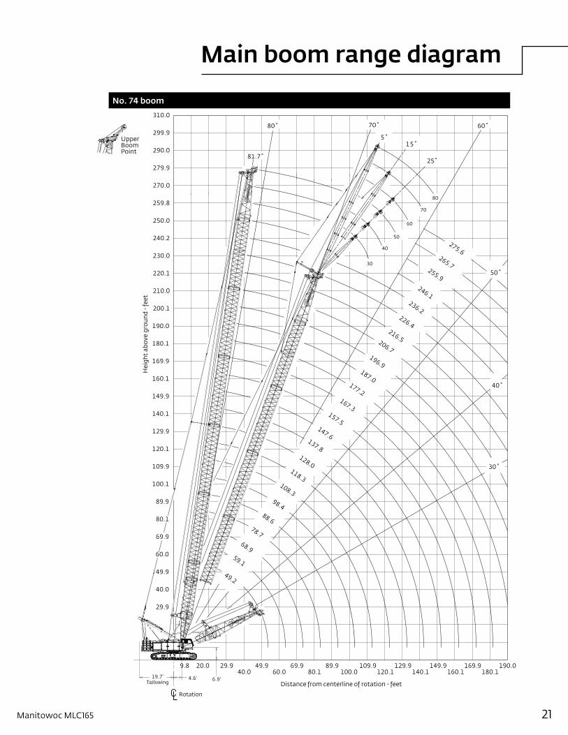
Main boom range diagram
21Manitowoc MLC165
No. 74 boom
Rotation
UpperBoomPoint
30˚
40˚
50˚
60˚
25˚
15˚5˚
70˚80˚
81.7˚
Distance from centerline of rotation - feet
Hei
ght
abov
e gr
ound
- fe
et
60.0
80.1
100.1
120.1
140.1
160.1
180.1
200.1
220.1
240.2
299.9
279.9
259.8
49.9
69.9
89.9
109.9
129.9
149.9
169.9
190.0
210.0
230.0
250.0
270.0
290.0
40.0
29.9
310.0
49.9 69.9 89.9 109.9 129.9 149.929.9 190.0169.940.0 60.0 80.1 100.0 120.1 140.1 160.1 180.1
9.8 20.0
60
30
40
50
70
80
265.7
236.2
196.9187.0
206.7
216.5
226.4
246.1
255.9
275.6
147.6
128.0
108.3
78.7
49.2
59.1
68.9
88.6
98.4
118.3
137.8
157.5
167.3
177.2
19.7'Tailswing
4.6' 6.9'
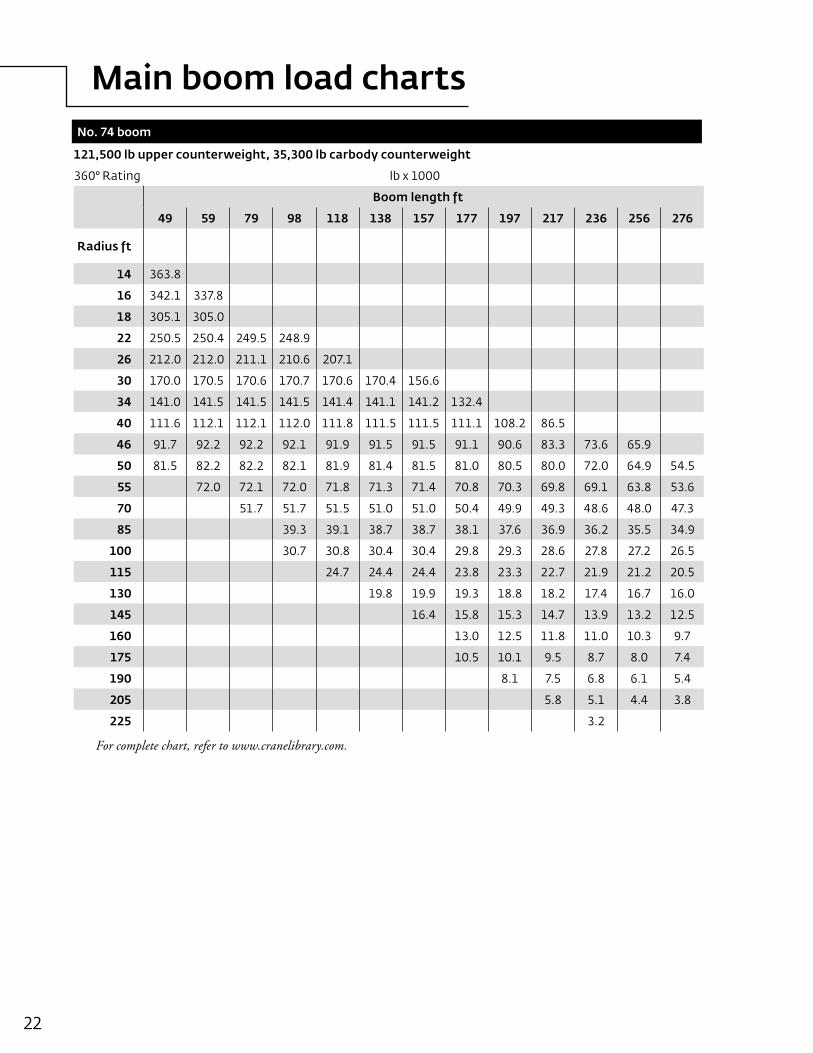
Main boom load charts
22
121,500 lb upper counterweight, 35,300 lb carbody counterweight
360° Rating lb x 1000
Boom length ft
49 59 79 98 118 138 157 177 197 217 236 256 276
Radius ft
14 363.8
16 342.1 337.8
18 305.1 305.0
22 250.5 250.4 249.5 248.9
26 212.0 212.0 211.1 210.6 207.1
30 170.0 170.5 170.6 170.7 170.6 170.4 156.6
34 141.0 141.5 141.5 141.5 141.4 141.1 141.2 132.4
40 111.6 112.1 112.1 112.0 111.8 111.5 111.5 111.1 108.2 86.5
46 91.7 92.2 92.2 92.1 91.9 91.5 91.5 91.1 90.6 83.3 73.6 65.9
50 81.5 82.2 82.2 82.1 81.9 81.4 81.5 81.0 80.5 80.0 72.0 64.9 54.5
55 72.0 72.1 72.0 71.8 71.3 71.4 70.8 70.3 69.8 69.1 63.8 53.6
70 51.7 51.7 51.5 51.0 51.0 50.4 49.9 49.3 48.6 48.0 47.3
85 39.3 39.1 38.7 38.7 38.1 37.6 36.9 36.2 35.5 34.9
100 30.7 30.8 30.4 30.4 29.8 29.3 28.6 27.8 27.2 26.5
115 24.7 24.4 24.4 23.8 23.3 22.7 21.9 21.2 20.5
130 19.8 19.9 19.3 18.8 18.2 17.4 16.7 16.0
145 16.4 15.8 15.3 14.7 13.9 13.2 12.5
160 13.0 12.5 11.8 11.0 10.3 9.7
175 10.5 10.1 9.5 8.7 8.0 7.4
190 8.1 7.5 6.8 6.1 5.4
205 5.8 5.1 4.4 3.8
225 3.2
No. 74 boom
For complete chart, refer to www.cranelibrary.com.
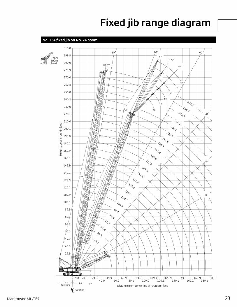
Fixed jib range diagram
23Manitowoc MLC165
No. 134 fixed jib on No. 74 boom
Rotation
UpperBoomPoint
30˚
40˚
50˚
60˚
25˚
15˚5˚
70˚80˚
81.7˚
Distance from centerline of rotation - feet
Hei
ght
abov
e gr
ound
- fe
et
60.0
80.1
100.1
120.1
140.1
160.1
180.1
200.1
220.1
240.2
299.9
279.9
259.8
49.9
69.9
89.9
109.9
129.9
149.9
169.9
190.0
210.0
230.0
250.0
270.0
290.0
40.0
29.9
310.0
49.9 69.9 89.9 109.9 129.9 149.929.9 190.0169.940.0 60.0 80.1 100.0 120.1 140.1 160.1 180.1
9.8 20.0
60
30
40
50
70
80
265.7
236.2
196.9187.0
206.7
216.5
226.4
246.1
255.9
275.6
147.6
128.0
108.3
78.7
49.2
59.1
68.9
88.6
98.4
118.3
137.8
157.5
167.3
177.2
19.7'Tailswing
4.6' 6.9'
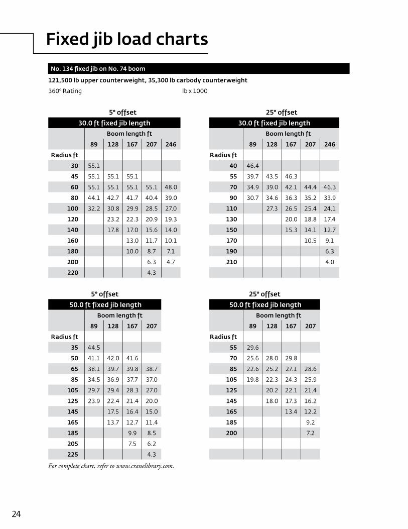
Fixed jib load charts
24
121,500 lb upper counterweight, 35,300 lb carbody counterweight
360° Rating lb x 1000
5° offset 25° offset
30.0 ft fixed jib length 30.0 ft fixed jib lengthBoom length ft Boom length ft
89 128 167 207 246 89 128 167 207 246
Radius ft Radius ft
30 55.1 40 46.4
45 55.1 55.1 55.1 55 39.7 43.5 46.3
60 55.1 55.1 55.1 55.1 48.0 70 34.9 39.0 42.1 44.4 46.3
80 44.1 42.7 41.7 40.4 39.0 90 30.7 34.6 36.3 35.2 33.9
100 32.2 30.8 29.9 28.5 27.0 110 27.3 26.5 25.4 24.1
120 23.2 22.3 20.9 19.3 130 20.0 18.8 17.4
140 17.8 17.0 15.6 14.0 150 15.3 14.1 12.7
160 13.0 11.7 10.1 170 10.5 9.1
180 10.0 8.7 7.1 190 6.3
200 6.3 4.7 210 4.0
220 4.3
5° offset 25° offset
50.0 ft fixed jib length 50.0 ft fixed jib lengthBoom length ft Boom length ft
89 128 167 207 89 128 167 207
Radius ft Radius ft
35 44.5 55 29.6
50 41.1 42.0 41.6 70 25.6 28.0 29.8
65 38.1 39.7 39.8 38.7 85 22.6 25.2 27.1 28.6
85 34.5 36.9 37.7 37.0 105 19.8 22.3 24.3 25.9
105 29.7 29.4 28.3 27.0 125 20.2 22.1 21.4
125 23.9 22.4 21.4 20.0 145 18.0 17.3 16.2
145 17.5 16.4 15.0 165 13.4 12.2
165 13.7 12.7 11.4 185 9.2
185 9.9 8.5 200 7.2
205 7.5 6.2
225 4.3
No. 134 fixed jib on No. 74 boom
For complete chart, refer to www.cranelibrary.com.
Fixed jib load charts
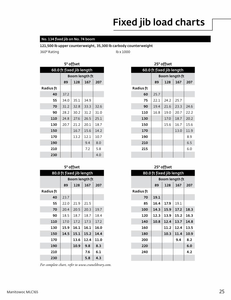
25Manitowoc MLC165
121,500 lb upper counterweight, 35,300 lb carbody counterweight
360° Rating lb x 1000
5° offset 25° offset
60.0 ft fixed jib length 60.0 ft fixed jib lengthBoom length ft Boom length ft
89 128 167 207 89 128 167 207
Radius ft Radius ft
40 37.2 60 25.7
55 34.0 35.1 34.9 75 22.1 24.2 25.7
70 31.2 32.8 33.3 32.6 90 19.4 21.6 23.3 24.6
90 28.2 30.2 31.2 31.0 110 16.8 19.0 20.7 22.2
110 24.8 27.6 26.5 25.1 130 17.0 18.7 20.2
130 20.7 21.2 20.1 18.7 150 15.6 16.7 15.6
150 16.7 15.6 14.2 170 13.0 11.9
170 13.2 12.1 10.7 190 8.9
190 9.4 8.0 210 6.5
210 7.2 5.8 215 6.0
230 4.0
5° offset 25° offset
80.0 ft fixed jib length 80.0 ft fixed jib lengthBoom length ft Boom length ft
89 128 167 207 89 128 167 207
Radius ft Radius ft
40 23.7 70 19.1
55 22.0 21.9 21.5 85 16.4 17.9 19.1
70 20.4 20.5 20.3 19.7 100 14.3 15.9 17.2 18.3
90 18.5 18.7 18.7 18.4 120 12.3 13.9 15.2 16.3
110 17.0 17.2 17.3 17.2 140 10.8 12.4 13.7 14.8
130 15.9 16.1 16.1 16.0 160 11.2 12.4 13.5
150 14.5 15.1 15.2 14.4 180 10.3 11.4 10.9
170 13.6 12.4 11.0 200 9.4 8.2
190 10.9 9.8 8.3 220 6.0
210 7.6 6.1 240 4.2
230 5.8 4.3
No. 134 fixed jib on No. 74 boom
For complete chart, refer to www.cranelibrary.com.
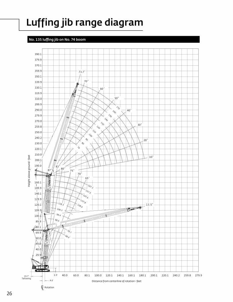
Luffing jib range diagram
26
No. 135 luffing jib on No. 74 boom
Rotation
Hei
ght
abov
e gr
ound
- fe
et
210.0
200.1
390.1
379.9
370.1
359.9
350.1
339.9
319.9
330.1
310.0
290.0
270.0
250.0
190.0
149.9
129.9
109.9
259.8
279.9
299.9
240.2
220.1
230.0
160.1
140.1
120.1
100.1
69.9
40.0
29.9
89.9
49.9
80.1
60.0
80.140.0 140.160.0 100.0 120.1 160.1 180.1 200.1 220.1 259.8240.2 279.9
Distance from centerline of rotation - feet
170 160
150 140
130 120
110 100
90
70
80
147.6
128.0
137'.8
157.5
167.3
108.3
88.6
98.4
118.3
78.7
68.9
6.9'
4.6'
19.7'Tailswing
70˚
60˚
50˚
40˚
30˚
20˚
10˚
83˚80˚
75˚70˚
65˚
73.7˚
87˚
13.5˚
Luffing jib load charts
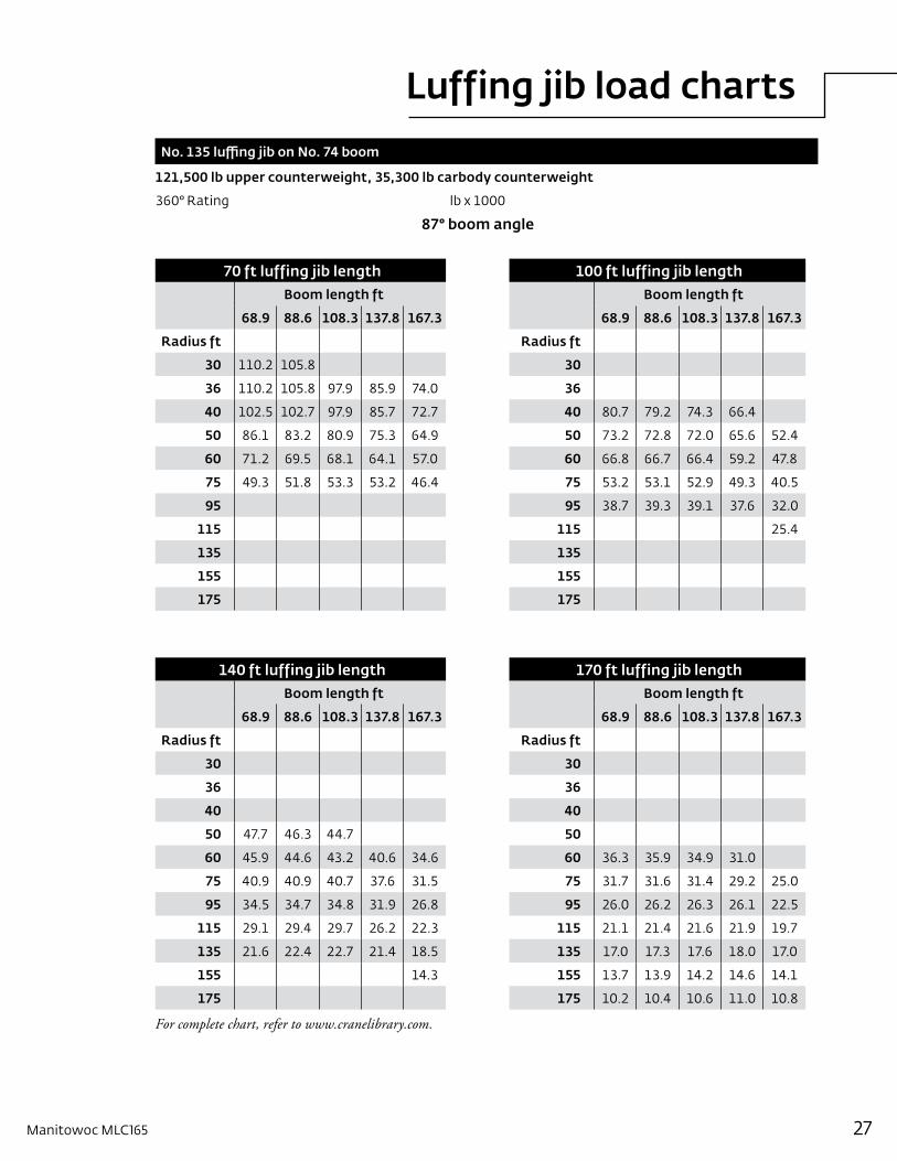
27Manitowoc MLC165
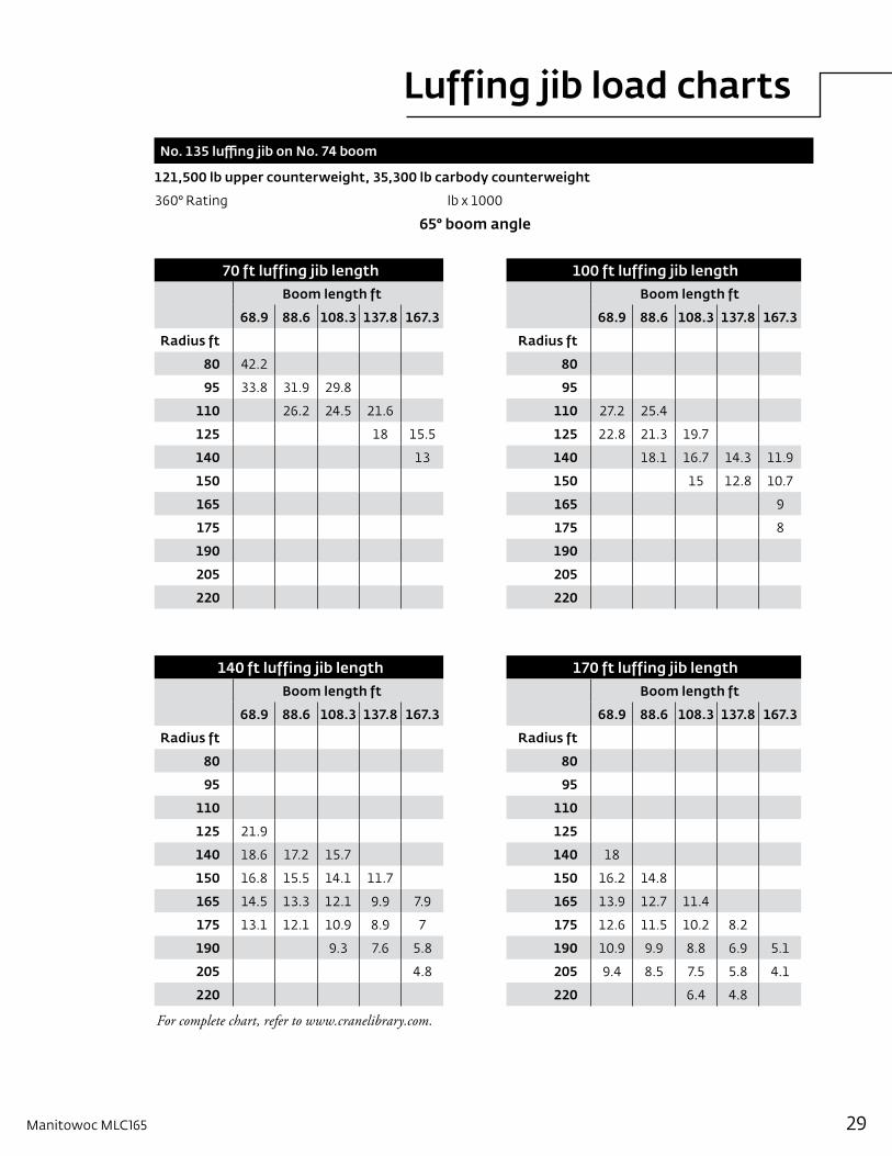
No. 135 luffing jib on No. 74 boom
121,500 lb upper counterweight, 35,300 lb carbody counterweight
360° Rating lb x 1000
87° boom angle
70 ft luffing jib length 100 ft luffing jib lengthBoom length ft Boom length ft
68.9 88.6 108.3 137.8 167.3 68.9 88.6 108.3 137.8 167.3
Radius ft Radius ft
30 110.2 105.8 30
36 110.2 105.8 97.9 85.9 74.0 36
40 102.5 102.7 97.9 85.7 72.7 40 80.7 79.2 74.3 66.4
50 86.1 83.2 80.9 75.3 64.9 50 73.2 72.8 72.0 65.6 52.4
60 71.2 69.5 68.1 64.1 57.0 60 66.8 66.7 66.4 59.2 47.8
75 49.3 51.8 53.3 53.2 46.4 75 53.2 53.1 52.9 49.3 40.5
95 95 38.7 39.3 39.1 37.6 32.0
115 115 25.4
135 135
155 155
175 175
140 ft luffing jib length 170 ft luffing jib lengthBoom length ft Boom length ft
68.9 88.6 108.3 137.8 167.3 68.9 88.6 108.3 137.8 167.3
Radius ft Radius ft
30 30
36 36
40 40
50 47.7 46.3 44.7 50
60 45.9 44.6 43.2 40.6 34.6 60 36.3 35.9 34.9 31.0
75 40.9 40.9 40.7 37.6 31.5 75 31.7 31.6 31.4 29.2 25.0
95 34.5 34.7 34.8 31.9 26.8 95 26.0 26.2 26.3 26.1 22.5
115 29.1 29.4 29.7 26.2 22.3 115 21.1 21.4 21.6 21.9 19.7
135 21.6 22.4 22.7 21.4 18.5 135 17.0 17.3 17.6 18.0 17.0
155 14.3 155 13.7 13.9 14.2 14.6 14.1
175 175 10.2 10.4 10.6 11.0 10.8
For complete chart, refer to www.cranelibrary.com.
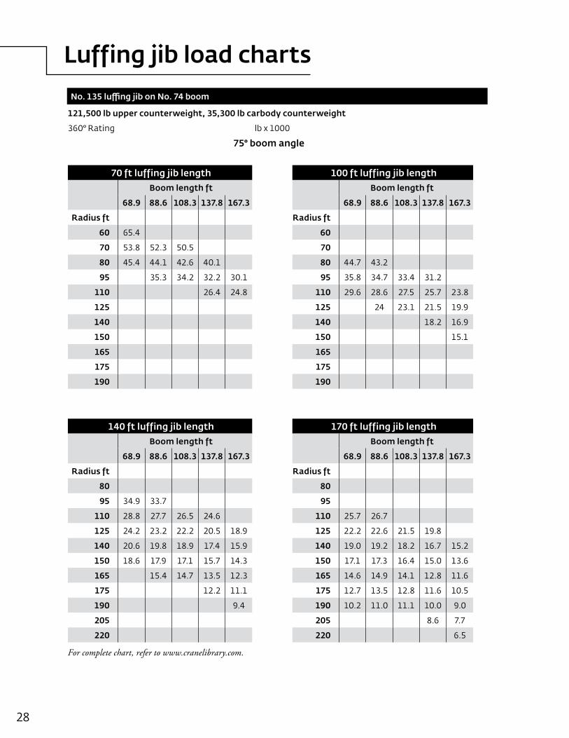
Luffing jib load charts
28
121,500 lb upper counterweight, 35,300 lb carbody counterweight
360° Rating lb x 1000
75° boom angle
70 ft luffing jib length 100 ft luffing jib lengthBoom length ft Boom length ft
68.9 88.6 108.3 137.8 167.3 68.9 88.6 108.3 137.8 167.3
Radius ft Radius ft
60 65.4 60
70 53.8 52.3 50.5 70
80 45.4 44.1 42.6 40.1 80 44.7 43.2
95 35.3 34.2 32.2 30.1 95 35.8 34.7 33.4 31.2
110 26.4 24.8 110 29.6 28.6 27.5 25.7 23.8
125 125 24 23.1 21.5 19.9
140 140 18.2 16.9
150 150 15.1
165 165
175 175
190 190
140 ft luffing jib length 170 ft luffing jib lengthBoom length ft Boom length ft
68.9 88.6 108.3 137.8 167.3 68.9 88.6 108.3 137.8 167.3
Radius ft Radius ft
80 80
95 34.9 33.7 95
110 28.8 27.7 26.5 24.6 110 25.7 26.7
125 24.2 23.2 22.2 20.5 18.9 125 22.2 22.6 21.5 19.8
140 20.6 19.8 18.9 17.4 15.9 140 19.0 19.2 18.2 16.7 15.2
150 18.6 17.9 17.1 15.7 14.3 150 17.1 17.3 16.4 15.0 13.6
165 15.4 14.7 13.5 12.3 165 14.6 14.9 14.1 12.8 11.6
175 12.2 11.1 175 12.7 13.5 12.8 11.6 10.5
190 9.4 190 10.2 11.0 11.1 10.0 9.0
205 205 8.6 7.7
220 220 6.5
No. 135 luffing jib on No. 74 boom
For complete chart, refer to www.cranelibrary.com.
Luffing jib load charts
29Manitowoc MLC165
121,500 lb upper counterweight, 35,300 lb carbody counterweight
360° Rating lb x 1000
65° boom angle
70 ft luffing jib length 100 ft luffing jib lengthBoom length ft Boom length ft
68.9 88.6 108.3 137.8 167.3 68.9 88.6 108.3 137.8 167.3
Radius ft Radius ft
80 42.2 80
95 33.8 31.9 29.8 95
110 26.2 24.5 21.6 110 27.2 25.4
125 18 15.5 125 22.8 21.3 19.7
140 13 140 18.1 16.7 14.3 11.9
150 150 15 12.8 10.7
165 165 9
175 175 8
190 190
205 205
220 220
140 ft luffing jib length 170 ft luffing jib lengthBoom length ft Boom length ft
68.9 88.6 108.3 137.8 167.3 68.9 88.6 108.3 137.8 167.3
Radius ft Radius ft
80 80
95 95
110 110
125 21.9 125
140 18.6 17.2 15.7 140 18
150 16.8 15.5 14.1 11.7 150 16.2 14.8
165 14.5 13.3 12.1 9.9 7.9 165 13.9 12.7 11.4
175 13.1 12.1 10.9 8.9 7 175 12.6 11.5 10.2 8.2
190 9.3 7.6 5.8 190 10.9 9.9 8.8 6.9 5.1
205 4.8 205 9.4 8.5 7.5 5.8 4.1
220 220 6.4 4.8
No. 135 luffing jib on No. 74 boom
For complete chart, refer to www.cranelibrary.com.
Manitowoc Crane Care
30
Manitowoc Crane Care is the industry’s most advanced service and support program, designed to keep your cranes up and running. Manitowoc’s distributor network and customer support personnel are available to support you 24 hours a day, 7 days a week, 365 days a year. There are five key disciplines of Manitowoc Crane Care:
PartsGenuine Manitowoc replacement parts are accessible through your distributor.
Service and technical supportAssistance with crane selection, lift planning and ground bearing calculations or field service and maintenance.
Technical publicationsOperator, parts, service and capacity chart manuals are available in multiple formats in major languages.
TrainingA variety of training courses are available online or through Manitowoc training centers.
EnCORERebuild, repair, remanufacture or exchange your current crane through our local network, for a fraction of the cost of a new crane.
www.manitowoccranecare.com
CraneSTAR is an exclusive and innovative crane asset management system that helps improve your profitability and reduce costs by remotely monitoring critical crane data. Visit www.cranestar.com for more information.

Notes
31Manitowoc MLC165

©2013 Manitowoc0313-MLC165 PG-US-E-ASME-Imperial www.manitowoccranes.com
This document is non-contractual. Constant improvement and engineering progress make it necessary that we reserve the right to make specification, equipment, and price changes without notice. Illustrations shown may include optional equipment and accessories and may not include all standard equipment.
Regional offices
ChinaShanghai, China Tel: +86 21 6457 0066Fax: +86 21 6457 4955
Greater Asia-Pacific Singapore Tel: +65 6264 1188 Fax: +65 6862 4040
Europe, Middle East, Africa Ecully, France Tel: +33 (0)4 72 18 20 20 Fax: +33 (0)4 72 18 20 00
Americas Manitowoc, Wisconsin, USA Tel: +1 920 684 6621 Fax: +1 920 683 6277
Shady Grove, Pennsylvania, USA Tel: +1 717 597 8121 Fax: +1 717 597 4062
Regional headquarters
Manitowoc Cranes
ChinaBeijingChengduGuangzhouXian
Greater Asia-PacificAustraliaBrisbaneMelbourneSydneyIndiaChennaiDelhiHyderabadPuneKoreaSeoulPhilippinesMakati CitySingapore
FactoriesBrazilPasso FundoChinaTaiAnZhangjiagangFranceCharlieuMoulinsGermanyWilhelmshavenIndiaPuneItalyNiella TanaroPortugalBaltarFânzeresSlovakiaSarisUSAManitowoc Port WashingtonShady Grove
AmericasBrazilAlphavilleMexicoMonterreyChileSantiago
Europe, Middle East, AfricaCzech RepublicNetvoriceFranceBaudemontCergyDecinesGermanyLangenfeldHungaryBudapestItalyLainateNetherlandsBredaPolandWarsawPortugalBaltarRussiaMoscowSouth AfricaJohannesburgU.A.E.DubaiU.K.Buckingham


![222 Product Guide[1] - CraneDude · Fast, efficient self-assembly Complete crane, maximum boom, fixed jib and counterweight ships on only 3 trucks Manitowoc CraneCARESM Manitowoc](https://img.pdfslide.net/doc/110x75/5b36128a7f8b9a3a6d8dde23/222-product-guide1-fast-efficient-self-assembly-complete-crane-maximum.jpg)