Embed Size (px)
Citation preview
Model 5081-P
Two-Wire pH/ORP Transmitter
Instruction ManualLIQ-MAN-5081P/rev.JJanuary 2015
Emerson Process Management
2400 Barranca ParkwayIrvine, CA 92606 uSATel: (949) 757-8500Fax: (949) 474-7250
http://www.raihome.com
© Rosemount Analytical Inc. 2014
ESSENTIAL INSTRUCTIONSREAD THIS PAGE BEFORE PROCEEDING!
Rosemount Analytical designs, manufactures, and tests its products to meet many national and internationalstandards. Because these instruments are sophisticated technical products, you must properly install, use, andmaintain them to ensure they continue to operate within their normal specifications. The following instructionsmust be adhered to and integrated into your safety program when installing, using, and maintaining RosemountAnalytical products. Failure to follow the proper instructions may cause any one of the following situations tooccur: Loss of life; personal injury; property damage; damage to this instrument; and warranty invalidation.
• Read all instructions prior to installing, operating, and servicing the product. If this Instruction Manual is not thecorrect manual, telephone 1-800-654-7768 and the requested manual will be provided. Save this InstructionManual for future reference.
• If you do not understand any of the instructions, contact your Rosemount representative for clarification.
• Follow all warnings, cautions, and instructions marked on and supplied with the product.
• Inform and educate your personnel in the proper installation, operation, and maintenance of the product.
• Install your equipment as specified in the Installation Instructions of the appropriate Instruction Manual and perapplicable local and national codes. Connect all products to the proper electrical and pressure sources.
• To ensure proper performance, use qualified personnel to install, operate, update, program, and maintain theproduct.
• When replacement parts are required, ensure that qualified people use replacement parts specified byRosemount. unauthorized parts and procedures can affect the product’s performance and place the safeoperation of your process at risk. Look alike substitutions may result in fire, electrical hazards, or improperoperation.
• Ensure that all equipment doors are closed and protective covers are in place, except when maintenance isbeing performed by qualified persons, to prevent electrical shock and personal injury.
CAUTIONIf a Model 375 universal Hart® Communicator is used with these transmitters, the software within the Model 375 may requiremodification. If a software modification is required, please contact your local Emerson Process Management Service Groupor National Response Center at 1-800-654-7768.
About This DocumentThis manual contains instructions for installation and operation of the Model 5081-P Two-WirepH/ORP Transmitter. The following list provides notes concerning all revisions of this document.
Rev. Level Date Notes
A 10/04 This is the initial release of the product manual. The manual has been reformatted to reflect the Emerson documentation style and updated to reflect any changes in the product offering. This manual contains information on HART Smart and FOuNdATION Fieldbus versions of 5081-P.
B 3/05 updated FM dwg & sensor compatibility chart.
C 4/05 Fixed drawings that changed in pdf conversion.
d 2/06 Added drawings, pages 52-60.
E 11/07 Added Mcerts to page 2.
F 06/09 Page 136 phone # change
G 1/11 updated Enclosure specifiations, updated ©
H 11/12 Added Fieldbus specifications, updated ITK revision and CE certifications
J 10/14 Changed agency water exposure testing description to “Type”.
i
MODEL 5081-P pH/ORP TABLE OF CONTENTS
MODEL 5081-P pH/ORPTwO-wIRE TRANSMITTER
TABLE OF CONTENTS
Section Title Page
1.0 DESCRIPTION AND SPECIFICATIONS ................................................................ 1
1.1 Features and Applications........................................................................................ 11.2 Specifications........................................................................................................... 21.3 Hazardous Location Approval .................................................................................. 31.4 Transmitter display during Calibration and Programming....................................... 51.5 Infrared Remote Controller ...................................................................................... 51.6 FOuNdATION Fieldbus............................................................................................... 51.7 General Specifications ............................................................................................. 51.8 HART Communications ........................................................................................... 61.9 Asset Management Solutions ................................................................................. 7
2.0 INSTALLATION ...................................................................................................... 9
2.1 unpacking and Inspection........................................................................................ 92.2 Pre-Installation Set up ............................................................................................. 92.3 Orienting the display Board ..................................................................................... 11 2.4 Mechanical Installation............................................................................................. 112.5 Power Supply/Current Loop Wiring for Model 5081-P-HT ....................................... 14 2.6 Power Supply Wiring for Model 5081-P-FF ............................................................. 15
3.0 wIRING ................................................................................................................... 16
3.1 General Information ................................................................................................. 16 3.2 Wiring diagrams ...................................................................................................... 17
4.0 INTRINSICALLy SAFE AND ExPLOSION PROOF INSTALLATIONS ................. 31
4.1 Intrinsically Safe and Explosion-Proof Installations for 5081-P-HT.......................... 32 4.2 Intrinsically Safe and Explosion-Proof Installations for 5081-P-FF .......................... 40 4.3 Intrinsically Safe and Explosion-Proof Installations for 5081-P-FI ........................... 48
5.0 OPERATION wITH REMOTE CONTROLLER ...................................................... 55
5.1 Overview .................................................................................................................. 555.2 displays ................................................................................................................... 565.3 Infrared Remote Controller (IRC) — Key Functions ................................................ 575.4 Menu Tree - pH ........................................................................................................ 585.5 diagnostic Messages - pH ....................................................................................... 585.6 Menu Tree -ORP...................................................................................................... 605.7 diagnostic Messages - ORP.................................................................................... 605.8 Security .................................................................................................................... 62
6.0 OPERATION wITH MODEL 375 ............................................................................ 63
6.1 Note on Model 375 or 475 HART Communicator .................................................... 636.2 Connecting the HART Communicator...................................................................... 636.3 Operation ................................................................................................................. 64
Continued on the following page
MODEL 5081-P pH/ORP TABLE OF CONTENTS
TABLE OF CONTENTS CONT’D
ii
7.0 CALIBRATION OF pH MEASUREMENTS ............................................................. 69
7.1 General .................................................................................................................... 697.2 Entering and Leaving the Calibrate Menu................................................................ 697.3 using the Hold Function........................................................................................... 697.4 Temperature Calibration........................................................................................... 707.5 Auto Calibration ....................................................................................................... 717.6 Manual Calibration ................................................................................................... 737.7 Making the Transmitter Reading Match a Second pH Meter (Standardization)....... 75
8.0 PROGRAMMING FOR pH MEASUREMENTS....................................................... 77
8.1 General .................................................................................................................... 778.2 Entering and Leaving the Program Menu ................................................................ 778.3 Output Ranging........................................................................................................ 798.4 diagnostic Parameters............................................................................................. 808.5 Temperature Related Settings ................................................................................. 848.6 display units ............................................................................................................ 868.7 Buffer Calibration Parameters.................................................................................. 878.8 Isopotential Parameters ........................................................................................... 898.9 Generating a Test Current........................................................................................ 91
9.0 CALIBRATION OF ORP MEASUREMENTS .......................................................... 92
9.1 General .................................................................................................................... 929.2 Entering and Leaving the Calibrate Menu................................................................ 929.3 using the Hold Function........................................................................................... 92 9.4 Temperature Calibration........................................................................................... 939.5 Standardization ........................................................................................................ 94
10.0 PROGRAMMING FOR ORP MEASUREMENTS.................................................... 95
10.1 General .................................................................................................................... 9510.2 Entering and Leaving the Program Menu ................................................................ 9510.3 Output Ranging........................................................................................................ 9710.4 Temperature Element............................................................................................... 9910.5 display units ............................................................................................................ 10010.6 diagnostic Parameters............................................................................................. 10110.7 Generating a Test Current........................................................................................ 104
11.0 MAINTENANCE ...................................................................................................... 105
11.1 Overview .................................................................................................................. 10511.2 Transmitter Maintenance ......................................................................................... 10511.3 pH Sensor Maintenance .......................................................................................... 106 11.4 ORP Sensor Maintenance ....................................................................................... 10811.5 Calibration................................................................................................................ 108
Continued on the following page
iii
MODEL 5081-P pH/ORP TABLE OF CONTENTS
TABLE OF CONTENTS CONT’D
12.0 TROUBLESHOOTING ........................................................................................... 109
12.1 Warning and Fault Messages .................................................................................. 10912.2 Calibration Errors ..................................................................................................... 11012.3 Troubleshooting - General ....................................................................................... 11012.4 Troubleshooting When a diagnostic Message is Showing ...................................... 11012.5 Troubleshooting When No diagnostic Message is Showing.................................... 12212.6 displaying diagnostic Variables............................................................................... 12712.7 Testing the Transmitter by Simulating pH ................................................................ 12712.8 Factory Assistance and Repairs .............................................................................. 130
13.0 pH MEASUREMENTS............................................................................................. 131
13.1 General .................................................................................................................... 13113.2 Measuring Electrode ................................................................................................ 13213.3 Reference Electrode ................................................................................................ 13213.4 Liquid Junction Potential .......................................................................................... 13313.5 Converting Voltage to pH ......................................................................................... 13313.6 Glass Electrode Slope ............................................................................................. 13413.7 Buffers and Calibration ............................................................................................ 13413.8 Isopotential pH ......................................................................................................... 13513.9 Junction Potential Mismatch .................................................................................... 13513.10 Sensor diagnostics .................................................................................................. 13613.11 Shields, Insulation, and Preamplifiers...................................................................... 136
14.0 ORP MEASUREMENTS.......................................................................................... 137
14.1 General .................................................................................................................... 13714.2 Measuring Electrode ................................................................................................ 13814.3 Reference Electrode ................................................................................................ 13814.4 Liquid Junction Potential .......................................................................................... 13814.5 Relating Cell Voltage to ORP................................................................................... 13914.6 ORP, Concentration, and pH.................................................................................... 13914.7 Interpreting ORP Measurements ............................................................................. 14014.8 Calibration................................................................................................................ 142
15.0 THEORy — REMOTE COMMUNICATIONS........................................................... 143
15.1 Overview of HART Communications........................................................................ 14315.2 HART Interface devices........................................................................................... 14315.3 Asset Management Solutions .................................................................................. 144
16.0 RETURN OF MATERIAL......................................................................................... 145
iv
MODEL 5081-P pH/ORP TABLE OF CONTENTS
LIST OF FIGURES
Number Title Page
1-1 Transmitter display during Calibration and Programming ....................................... 5
1-2 Infrared Remote Controller....................................................................................... 5
1-3 Configuring Model 5081 Transmitter with FOuNdATION Fieldbus ............................. 6
1-4 HART Communicator ............................................................................................... 7
1-5 AMS Main Menu Tools ............................................................................................. 8
2-1 Mounting the Model 5081-P pH/ORP Transmitter on a Flat Surface........................ 12
2-2 using the Pipe Mounting Kit to Attach the Model 5081-P pH/ORP to a pipe............ 13
2-3 Load/Power Supply Wiring ....................................................................................... 14
2-4 Model 5081-P-HT Power Wiring details................................................................... 14
2-5 Typical Fieldbus Network Electrical Wiring Configuration ........................................ 15
2-6 Model 5081-P-FF Power Wiring details ................................................................... 15
3-1 Wiring and Preamplifier Configurations for pH and ORP Sensors ........................... 16
3-2 Wire Functions for Models 399-02, 399-09, 381pH-30-41, and 381pHE-31-41before removing BNC and terminating cable ........................................................... 20
3-3 Wire Functions for Models 399-02, 399-09, 381pH-30-41, and 381pHE-31-41after removing BNC and terminating cable. Wire Functions for Models 399-09-10-62, 381pH-30-42, and 381pHE-31-42 as received ................................. 20
3-4 Wiring diagram for Models 399-02, 399-09, 381pH-30-41, and 381pHE-31-41after removing BNC and terminating cable. Wiring diagram for Models 399-09-10-62,381pH-30-42, and 381pHE-31-42 as received. Wiring directly to the transmitter .... 20
3-5 Wiring diagram for Models 399-02, 399-09, 381pH-30-41 after removing BNC and terminating cable. Wiring diagram for Model 399-09-10-62, 381pH-30-42, and 381pH-31-42 as received. Wiring through a remote junction box to the transmitter 20
3-6 Wire Functions for Models 397-50, 397-54, 396-50, 396-54, 396R-50-60, 396R-54-60,389-02-50, and 389-02-54 before removing BNC and terminating cable................. 21
3-7 Wire Functions for Models 397-50, 397-54, 369-50, 396-54, 396R-50-60, 396R-54-60,389-02-50, and 389-02-54 after removing BNC and terminating cable. Wire Functions for Models 397-54-62, 396-02-62, and 389-02-54-62 as received .......... 21
3-8 Wiring diagram for Models 397-50, 397-54, 369-50, 396-54, 389-02-50, and.........389-02-54 after removing BNC and terminating cable. Wiring diagram for Models 397-54-62, 396-02-62, and 389-02-54-62 as received. Wiring directly to the Transmitter .................................................................................................... 21
3-9 Wiring diagram for Models 397-50, 397-54, 369-50, 396-54, 396R-50-60, 396R-54-60,389-02-50, and 389-02-54 after removing BNC and terminating cable. Wiring diagram for Models 397-54-62, 396-02-62, and 389-02-54-62 as received. Wiring Through a Remote Junction Box to the Transmitter ..................................... 21
3-10 Wire Functions for Models 396R-50, 396R-54, 396R-50-61, 396P-02-50, 396P-02-54, 396P-05-55, 385+-04, and 385+-41-52.................................................................... 22
3-11 Wiring diagram for Models 396R-50, 396R-54, 396R-50-61, 396P-02-50, 396P-02-54,396P-05-55, 385+-04, and 385+-41-52. Wiring directly to the Transmitter ............ 22
3-12 Wiring diagram for Models 396R-50, 396R-54, 396R-54-61, 396P-02-50, 396P-02-54,396P-02-55, 385+-04, and 385+-41-52. Wiring Through a Sensor-Mounted Junction Box to the Transmitter ............................................................................... 22
3-13 Wire Functions for Models 396P-01-55, 385+-03, 381+-40-55, and 381+-43-55 .... 23
3-14 Wiring diagram for Models 396P-01-55, 385+-03, 381+-40-55, and 381+-43-55.... 23
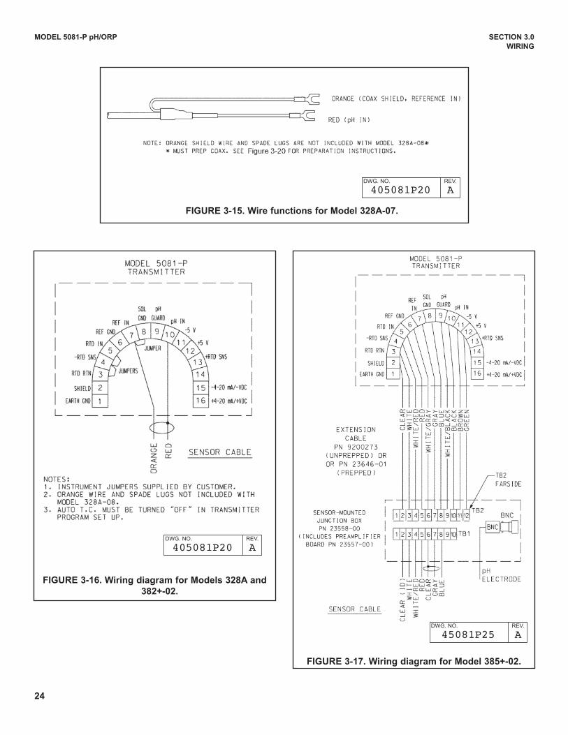
3-15 Wire Functions for Model 328A-07........................................................................... 24
3-16 Wiring diagram for Models 328A and 385+-02 ........................................................ 24
3-17 Wiring diagram for Model 385+-02 .......................................................................... 24
v
MODEL 5081-P pH/ORP TABLE OF CONTENTS
LIST OF FIGURES - CONT’D
Number Title Page
3-18 Wiring diagram for Model 320HP-10-55 .................................................................. 253-19 Wiring diagram for Model 320HP-10-58 .................................................................. 253-20 Procedure for Removing BNC Connector and Preparing Coaxial Cable for
Connection to the Model 5081-P pH/ORP Transmitter............................................. 263-21 Preparation of Raw Connecting Cable ..................................................................... 274-1 Model 5081-P-HT Infrared Remote Control — CSA, FM, & ATEX approvals .......... 314-2 Model 5081-P-FF Infrared Remote Control — CSA, FM, & ATEX approvals........... 314-3 FM Explosion-Proof Installation for Model 5081-P-HT ............................................. 324-4 FM Intrinsically Safe Label for Model 5081-P-HT..................................................... 334-5 FM Intrinsically Safe Installation for Model 5081-P-HT ............................................ 344-6 CSA Intrinsically Safe Label for Model 5081-P-HT................................................... 364-7 CSA Intrinsically Safe Installation for Model 5081-P-HT .......................................... 374-8 ATEX Intrinsically Safe Label for Model 5081-P-HT................................................. 394-9 FM Explosion-Proof Installation for Model 5081-P-FF ............................................. 404-10 FM Intrinsically Safe Label for Model 5081-P-FF ..................................................... 414-11 FM Intrinsically Safe Installation for Model 5081-P-FF............................................. 424-12 CSA Intrinsically Safe Label for Model 5081-P-FF ................................................... 444-13 CSA Intrinsically Safe Installation for Model 5081-P-FF........................................... 454-14 ATEX Intrinsically Safe Label for Model 5081-P-FF ................................................. 474-15 FM Intrinsically Safe Label for Model 5081-P-FI ...................................................... 484-16 FM Intrinsically Safe Installation for Model 5081-P-FI.............................................. 494-17 CSA Intrinsically Safe Label for Model 5081-P-FI .................................................... 514-18 CSA Intrinsically Safe Installation for Model 5081-P-FI............................................ 524-19 ATEX Intrinsically Safe Label for Model 5081-P-FI .................................................. 545-1 Functional Block diagram for the Model 5081-P pH/ORP Transmitter with
FOuNdATION Fieldbus ............................................................................................. 555-2 Process display Screen ........................................................................................... 565-3 Program display Screen .......................................................................................... 565-4 Infrared Remote Controller....................................................................................... 575-5 pH Menu Tree for Model 5081-P-HT ........................................................................ 585-6 pH Menu Tree for Model 5081-P-FF ....................................................................... 595-7 ORP Menu Tree for Model 5081-P-HT .................................................................... 605-8 ORP Menu Tree for Model 5081-P-FF .................................................................... 616-1 Connecting the HART Communicator ..................................................................... 636-2 5081-P-HT HART / Model 375 Menu Tree ............................................................... 658-1 Suggested Glass Impedance Warning and Failure Limits ....................................... 808-2 Suggested Warning and Failure Limits for Low Impedance Reference Electrodes . 818-3 Suggested Warning and Failure Limits for High Impedance Glass Reference Electrodes 8110-1 Suggested Warning and Failure Limits for Low Impedance Reference Electrodes . 10110-2 Suggested Glass Impedance Warning and Failure Limits for a Glass Reference
Electrode .................................................................................................................. 10111-1 Checking the Potential of the Reference Electrode.................................................. 10712-1 Warning Annunciation............................................................................................... 10912-2 Fault Annunciation.................................................................................................... 10912-3 Three-Wire RTd .................................................................................................... 11612-4 Temperature Simulation into the Model 5081-P pH/ORP Transmitter ...................... 11612-5 pH Simulation When the Preamplifier is Located in the Transmitter ........................ 12812-6 pH Simulation When the Preamplifier is Located in a Remote Junction Box or
in a Sensor-Mounted Junction Box .......................................................................... 128
vi
MODEL 5081-P pH/ORP TABLE OF CONTENTS
LIST OF FIGURES - CONT’D12-7 Simulate pH Through Model 381+ Sensor Preamplifier ........................................... 12913-1 pH Measurement Cell............................................................................................... 13113-2 Measuring Electrode (pH) ........................................................................................ 13213-3 Cross-Section Through the pH Glass....................................................................... 13213-4 Reference Electrode................................................................................................. 13313-5 The Origin of Liquid Junction Potential..................................................................... 13313-6 Glass Electrode Slope.............................................................................................. 13413-7 Two-Point Buffer Calibration..................................................................................... 13613-8 Liquid Junction Potential Mismatch .......................................................................... 13614-1 ORP Measurement Cell ........................................................................................... 13714-2 Measuring Electrode (ORP) ..................................................................................... 13814-3 Reference Electrode................................................................................................. 13814-4 The Origin of Liquid Junction Potential..................................................................... 13914-5 Electrode Potential ................................................................................................... 13914-6 ORP Measurement Interpretation ............................................................................ 14015-1 HART Communications ............................................................................................ 14315-2 AMS Main Menu Tools ............................................................................................. 144
LIST OF TABLES
Number Title Page
3-1 Wiring diagrams for Model 399 Sensors.................................................................. 173-2 Wiring diagrams for Model 397 Sensors.................................................................. 173-3 Wiring diagrams for Model 396R Sensors ............................................................... 173-4 Wiring diagrams for Model 396P Sensors ............................................................... 183-5 Wiring diagrams for Model 396 Sensors.................................................................. 183-6 Wiring diagrams for Model 389 Sensors.................................................................. 183-7 Wiring diagrams for Model 385+ Sensors................................................................ 193-8 Wiring diagrams for Model 381+ Sensors................................................................ 193-9 Wiring diagrams for Model 381pHE and 381pH Sensors ........................................ 193-10 Wiring diagrams for Model 328A Sensors ............................................................... 193-11 Wiring diagrams for Model 320HP Sensors............................................................. 198-1 pH Settings List ....................................................................................................... 788-2 pH Values of Standard Buffer Solutions and the Temperature Range over which
pH Values are defined ............................................................................................. 878-3 pH Values of Commercial (technical) Buffers and the Temperature Range over
which pH Values are defined .................................................................................. 888-4 Standard and Technical Buffers Recognized by the Model 5081-P pH Transmitter 8810-1 ORP Settings List .................................................................................................... 9611-1 Replacement Parts for Model 5081-P pH Transmitter ............................................. 10612-1 RTd Resistance Values ........................................................................................... 116
1
MODEL 5081-P pH/ORP SECTION 1.0
DESCRIPTION AND SPECIFICATIONS
SECTION 1.0DESCRIPTION AND SPECIFICATIONS
• CHOICE OF COMMuNICATION PROTOCOL: HART® or FOuNdATION Fieldbus.
• LARGE, EASY-TO-REAd two-line display shows the process measurement and temperature.
• SIMPLE MENu STRuCTuRE.
• ROBuST TYPE 4X ENCLOSuRE.
• INTRINSICALLY SAFE dESIGN allows the transmitter to be used in hazardous environments(with appropriate safety barriers).
• NON-VOLATILE MEMORY retains program settings and calibration data during power failures.
• CHANGING FROM pH TO ORP operation takes only seconds.
• AuTOMATIC TWO-POINT BuFFER CALIBRATION reduces errors.
• SOLuTION TEMPERATuRE COMPENSATION converts measured pH to the pH at 25°C.
• CONTINuOuS dIAGNOSTICS monitor sensor performance and warn the user of failure (FAuLT)or approaching failure (WARNING).
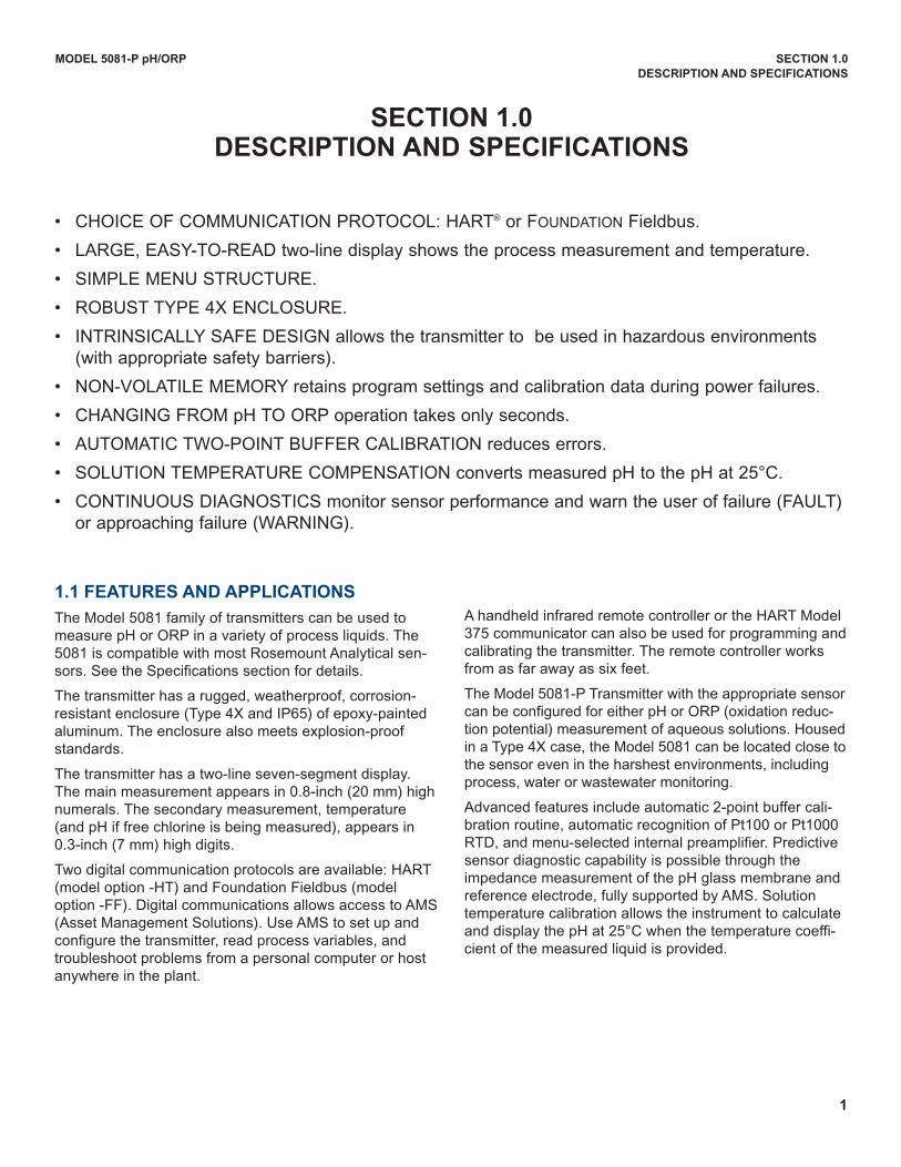
1.1 FEATURES AND APPLICATIONS
The Model 5081 family of transmitters can be used tomeasure pH or ORP in a variety of process liquids. The5081 is compatible with most Rosemount Analytical sen-sors. See the Specifications section for details.
The transmitter has a rugged, weatherproof, corrosion-resistant enclosure (Type 4X and IP65) of epoxy-paintedaluminum. The enclosure also meets explosion-proofstandards.
The transmitter has a two-line seven-segment display.The main measurement appears in 0.8-inch (20 mm) highnumerals. The secondary measurement, temperature(and pH if free chlorine is being measured), appears in0.3-inch (7 mm) high digits.
Two digital communication protocols are available: HART(model option -HT) and Foundation Fieldbus (modeloption -FF). digital communications allows access to AMS(Asset Management Solutions). use AMS to set up andconfigure the transmitter, read process variables, andtroubleshoot problems from a personal computer or hostanywhere in the plant.
A handheld infrared remote controller or the HART Model375 communicator can also be used for programming andcalibrating the transmitter. The remote controller worksfrom as far away as six feet.
The Model 5081-P Transmitter with the appropriate sensorcan be configured for either pH or ORP (oxidation reduc-tion potential) measurement of aqueous solutions. Housedin a Type 4X case, the Model 5081 can be located close tothe sensor even in the harshest environments, includingprocess, water or wastewater monitoring.
Advanced features include automatic 2-point buffer cali-bration routine, automatic recognition of Pt100 or Pt1000RTd, and menu-selected internal preamplifier. Predictivesensor diagnostic capability is possible through theimpedance measurement of the pH glass membrane andreference electrode, fully supported by AMS. Solutiontemperature calibration allows the instrument to calculateand display the pH at 25°C when the temperature coeffi-cient of the measured liquid is provided.
2
MODEL 5081-P pH/ORP SECTION 1.0
DESCRIPTION AND SPECIFICATIONS
1.2 SPECIFICATIONS
1.2.1 GENERAL SPECIFICATIONS
Housing: Cast aluminum with epoxy coating. Type 4X(IP65). Neoprene O-ring cover seals.
Dimensions: 160.5 mm x 175.3 mm x 161.3 mm (6.3 in.x 6.9 in. x 6.4 in.) See drawing.
Conduit Openings: ¾-in. FNPT
Ambient Temperature: -4 to 149°F (-20 to 65°C)
Storage Temperature: -22 to 176°F (-30 to 80°C)
Relative Humidity: 0 to 95% (non-condensing)
weight/Shipping weight: 10 lb/10 lb (4.5/5.0 kg)
Display: Two-line LCd; first line shows process variable(pH, ORP, conductivity, % concentration, oxygen,ozone, or chlorine), second line shows process tem-perature and output current. For pH/chlorine combina-tion, the second line can be toggled to show pH. Faultand warning messages, when triggered, alternate withtemperature and output readings.
First line: 7 segment LCd, 0.8 in. (20 mm) high.
Second line: 7 segment LCd, 0.3 in. (7mm) high.
display board can be rotated 90 degrees clockwise orcounterclockwise.
during calibration and programming, messages andprompts appear in the second line.
Temperature resolution: 0.1°C
Hazardous Location Approval: For details, see specifi-cations for the measurement of interest.
RFI/EMI: EN-61326
Digital Communications:
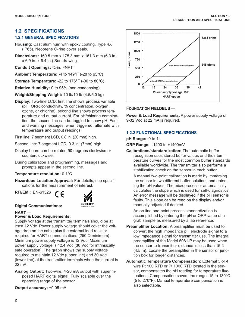
HART —Power & Load Requirements:
Supply voltage at the transmitter terminals should be atleast 12 Vdc. Power supply voltage should cover the volt-age drop on the cable plus the external load resistorrequired for HART communications (250 W minimum).Minimum power supply voltage is 12 Vdc. Maximumpower supply voltage is 42.4 Vdc (30 Vdc for intrinsicallysafe operation). The graph shows the supply voltagerequired to maintain 12 Vdc (upper line) and 30 Vdc(lower line) at the transmitter terminals when the current is22 mA.
Analog Output: Two-wire, 4-20 mA output with superim-posed HART digital signal. Fully scalable over theoperating range of the sensor.
Output accuracy: ±0.05 mA
FOUNDATION FIELDBUS —
Power & Load Requirements: A power supply voltage of9-32 Vdc at 22 mA is required.
1.2.2 FUNCTIONAL SPECIFICATIONS
pH Range: 0 to 14
ORP Range: -1400 to +1400mV
Calibrations/standardization: The automatic bufferrecognition uses stored buffer values and their tem-perature curves for the most common buffer standardsavailable worldwide. The transmitter also performs astabilization check on the sensor in each buffer.
A manual two-point calibration is made by immersingthe sensor in two different buffer solutions and enter-ing the pH values. The microprocessor automaticallycalculates the slope which is used for self-diagnostics.An error message will be displayed if the pH sensor isfaulty. This slope can be read on the display and/ormanually adjusted if desired.
An on-line one-point process standardization isaccomplished by entering the pH or ORP value of agrab sample as measured by a lab reference.
Preamplifier Location: A preamplifier must be used toconvert the high impedance pH electrode signal to alow impedance signal for transmitter use. The integralpreamplifier of the Model 5081-P may be used whenthe sensor to transmitter distance is less than 15 ft(4.5 m). Locate the preamplifier in the sensor or junc-tion box for longer distances.
Automatic Temperature Compensation: External 3 or 4wire Pt 100 RTd or Pt 1000 RTd located in the sen-sor, compensates the pH reading for temperature fluc-tuations. Compensation covers the range -15 to 130°C(5 to 270°F). Manual temperature compensation isalso selectable.
HART option
Sira MC070112/00
Non-Incendive:
Class I, div. 2, Groups A-d
dust Ignition Proof
Class II & III, div. 1, Groups E-G
Type 4X Enclosure
Class I, div. 2, Groups A-d
Suitable for
Class II, div. 2, Groups E-G
T4 Tamb = 70°C
Explosion-Proof:
Class I, div. 1, Groups B-d
Class II, div. 1, Groups E-G
Class III, div. 1
Class I, Groups B-d
Class II, Groups E-G
Class III
Tamb = 65°C max
MODEL 5081-P pH/ORP SECTION 1.0
DESCRIPTION AND SPECIFICATIONS
Accuracy: ±1 mV @ 25°C ±0.01 pH
Repeatability: ±1 mV @ 25°C ±0.01 pH
Stability: 0.25% / year @ 25°C
Diagnostics: The internal diagnostics can detect:
Calibration Error Low Temperature Error
High Temperature Error Sensor Failure
Line Failure CPu Failure
ROM Failure Input Warning
Glass Failure Glass Warning
Reference Failure Reference Warning Once one of the above is diagnosed, the LCd will display a message describing the failure/default detected.
Digital Communications as applicable by model:
HART (pH): PV assigned to pH. SV, TV, and 4V assignable to pH, temperature, mV, glass impedance, referenceimpedance, or RTd resistance.
HART (ORP): PV assigned to ORP. SV, TV, and 4V assignable to ORP, temperature, reference impedance, or RTdresistance.
Fieldbus (pH): Four AI blocks assigned to pH, temperature, reference impedance, and glass impedance.
Fieldbus (ORP): Three AI blocks assigned to ORP, temperature, and reference impedance.
3
1.3 HAzARDOUS LOCATION APPROvAL
Intrinsic Safety:
Class I, II, III, div. 1
Groups A-G
T4 Tamb = 70°C
Exia Entity
Class I, Groups A-d
Class II, Groups E-G
Class III
T4 Tamb = 70°C
IECEx BAS 09.0159X
Ex ia IIC T4 Ga
0600 II 1 G
Baseefa02ATEX1284
EEx ia IIC T4
Tamb = -20°C to +65°C
ATEx and IECEx Special Conditions for Use: The model5081 enclosure is made of aluminum alloy and is given a pro-tective polyurethane paint finish. However, care should be takento protect it from impact or abrasion if located in a zone 0 haz-ardous area.
ATEx
4
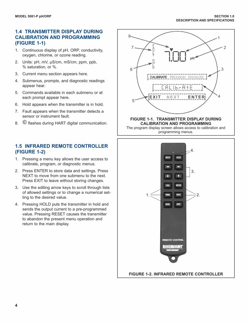
1.4 TRANSMITTER DISPLAy DURINGCALIBRATION AND PROGRAMMING(FIGURE 1-1)
1. Continuous display of pH, ORP, conductivity,oxygen, chlorine, or ozone reading.
2. units: pH, mV, µS/cm, mS/cm, ppm, ppb,% saturation, or %.
3. Current menu section appears here.
4. Submenus, prompts, and diagnostic readingsappear hear.
5. Commands available in each submenu or ateach prompt appear here.
6. Hold appears when the transmitter is in hold.
7. Fault appears when the transmitter detects asensor or instrument fault.
8. © flashes during HART digital communication.
1.5 INFRARED REMOTE CONTROLLER(FIGURE 1-2)
1. Pressing a menu key allows the user access tocalibrate, program, or diagnostic menus.
2. Press ENTER to store data and settings. PressNEXT to move from one submenu to the next.Press EXIT to leave without storing changes.
3. use the editing arrow keys to scroll through listsof allowed settings or to change a numerical set-ting to the desired value.
4. Pressing HOLd puts the transmitter in hold andsends the output current to a pre-programmedvalue. Pressing RESET causes the transmitterto abandon the present menu operation andreturn to the main display.
FIGURE 1-2. INFRARED REMOTE CONTROLLER
1.
4.
3.
2.
FIGURE 1-1. TRANSMITTER DISPLAy DURINGCALIBRATION AND PROGRAMMING
The program display screen allows access to calibration andprogramming menus.
MODEL 5081-P pH/ORP SECTION 1.0
DESCRIPTION AND SPECIFICATIONS
5
MODEL 5081-P pH/ORP SECTION 1.0
DESCRIPTION AND SPECIFICATIONS
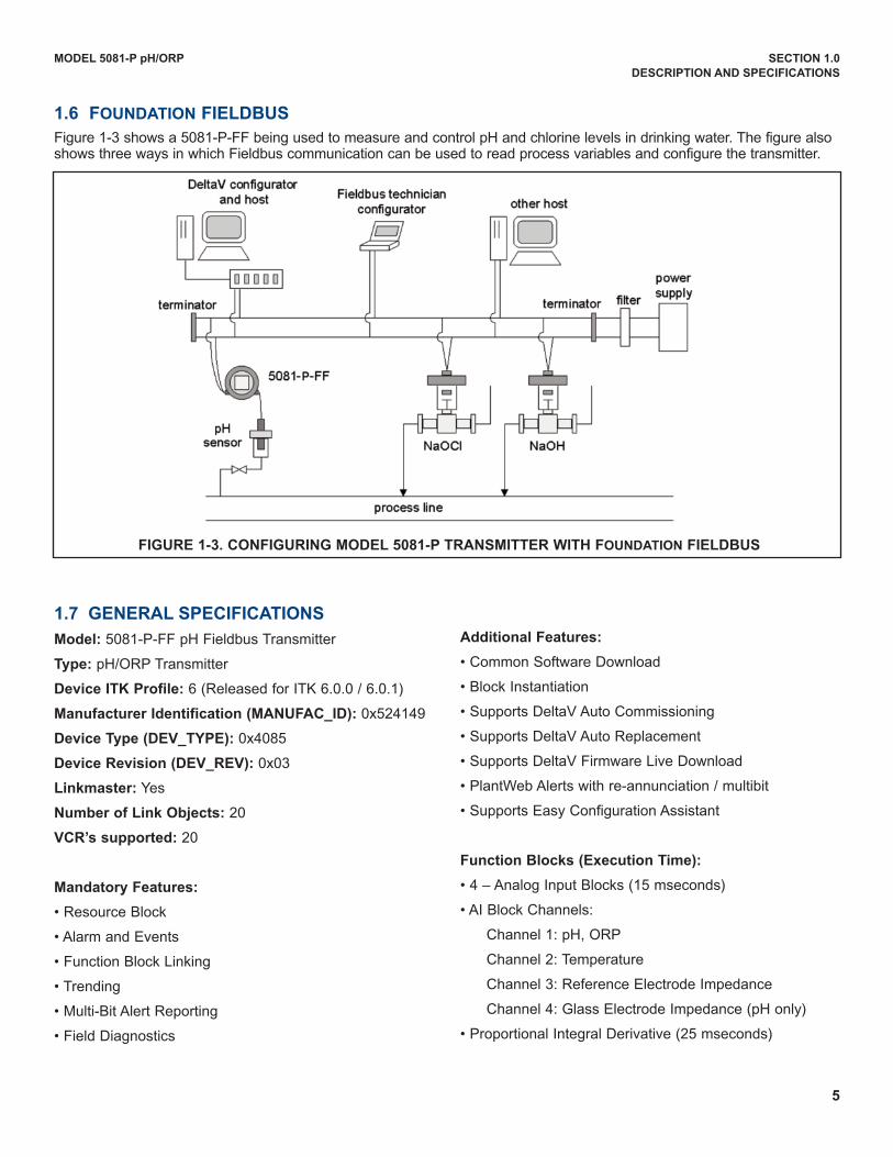
1.6 FOUNDATION FIELDBUS
Figure 1-3 shows a 5081-P-FF being used to measure and control pH and chlorine levels in drinking water. The figure alsoshows three ways in which Fieldbus communication can be used to read process variables and configure the transmitter.
FIGURE 1-3. CONFIGURING MODEL 5081-P TRANSMITTER wITH FOUNDATION FIELDBUS
1.7 GENERAL SPECIFICATIONS
Model: 5081-P-FF pH Fieldbus Transmitter
Type: pH/ORP Transmitter
Device ITK Profile: 6 (Released for ITK 6.0.0 / 6.0.1)
Manufacturer Identification (MANUFAC_ID): 0x524149
Device Type (DEv_TyPE): 0x4085
Device Revision (DEv_REv): 0x03
Linkmaster: Yes
Number of Link Objects: 20
vCR’s supported: 20
Mandatory Features:
• Resource Block
• Alarm and Events
• Function Block Linking
• Trending
• Multi-Bit Alert Reporting
• Field diagnostics
Additional Features:
• Common Software download
• Block Instantiation
• Supports deltaV Auto Commissioning
• Supports deltaV Auto Replacement
• Supports deltaV Firmware Live download
• PlantWeb Alerts with re-annunciation / multibit
• Supports Easy Configuration Assistant
Function Blocks (Execution Time):
• 4 – Analog Input Blocks (15 mseconds)
• AI Block Channels:
Channel 1: pH, ORP
Channel 2: Temperature
Channel 3: Reference Electrode Impedance
Channel 4: Glass Electrode Impedance (pH only)
• Proportional Integral derivative (25 mseconds)
MODEL 5081-P pH/ORP SECTION 1.0
DESCRIPTION AND SPECIFICATIONS
1.8 HART COMMUNICATIONS
1.8.1 OvERvIEw OF HART COMMUNICATION
HART (highway addressable remote transducer) is a digital communication system in which two frequencies are superim-posed on the 4 to 20 mA output signal from the transmitter. A 1200 Hz sine wave represents the digit 1, and a 2400 Hzsine wave represents the digit 0. Because the average value of a sine wave is zero, the digital signal adds no dc compo-nent to the analog signal. HART permits digital communication while retaining the analog signal for process control.
The HART protocol, originally developed by Fisher-Rosemount, is now overseen by the independent HARTCommunication Foundation. The Foundation ensures that all HART devices can communicate with one another. For moreinformation about HART communications, call the HART Communication Foundation at (512) 794-0369. The internetaddress is http://www.hartcomm.org.
1.8.2 HART INTERFACE DEvICES
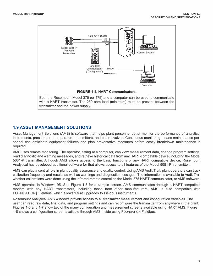
HART communicators allow the user to view measurement data (pH, ORP and temperature), program the transmitter, anddownload information from the transmitter for transfer to a computer for analysis. downloaded information can also be sentto another HART transmitter. Either a hand-held communicator, such as the Rosemount Model 375, or a computer can beused. HART interface devices operate from any wiring termination point in the 4 - 20 mA loop. A minimum load of 250 ohmsmust be present between the transmitter and the power supply. See Figure 1-4.
If your communicator does not recognize the Model 5081 pH/ORP transmitter, the device description library may needupdating. Call the manufacturer of your HART communication device for updates.
6
Power:
• Two Wire device; Fieldbus Polarity Insensitive
• Current draw: 21 mA
• device Certifications: IS / FISCO
• Maximum certified input Voltage for IS: 30V
• Maximum certified input current for IS: 300mA
• Maximum certified input power for IS: 1.3W
• Internal Capacitance (Ci): 0 nF
• Internal Inductance (Li): 0 μH
7
MODEL 5081-P pH/ORP SECTION 1.0
DESCRIPTION AND SPECIFICATIONS
4-20 mA + digital250 ohm
Control System
Computer
Model 5081-P Two-wire
Transmitter
BridgeHand Held
Communicator(“Configurator”)
FIGURE 1-4. HART Communicators.
Both the Rosemount Model 375 (or 475) and a computer can be used to communicatewith a HART transmitter. The 250 ohm load (minimum) must be present between thetransmitter and the power supply.
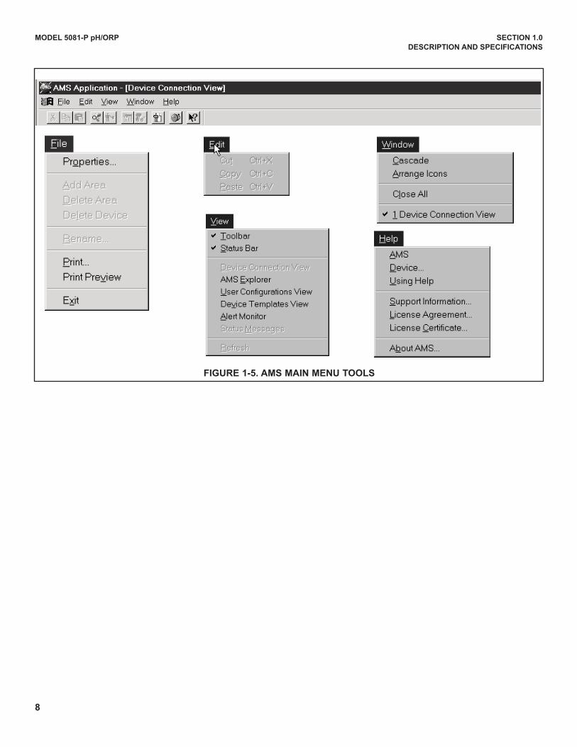
1.9 ASSET MANAGEMENT SOLUTIONS
Asset Management Solutions (AMS) is software that helps plant personnel better monitor the performance of analyticalinstruments, pressure and temperature transmitters, and control valves. Continuous monitoring means maintenance per-sonnel can anticipate equipment failures and plan preventative measures before costly breakdown maintenance isrequired.
AMS uses remote monitoring. The operator, sitting at a computer, can view measurement data, change program settings,read diagnostic and warning messages, and retrieve historical data from any HART-compatible device, including the Model5081-P transmitter. Although AMS allows access to the basic functions of any HART compatible device, RosemountAnalytical has developed additional software for that allows access to all features of the Model 5081-P transmitter.
AMS can play a central role in plant quality assurance and quality control. using AMS Audit Trail, plant operators can trackcalibration frequency and results as well as warnings and diagnostic messages. The information is available to Audit Trailwhether calibrations were done using the infrared remote controller, the Model 375 HART communicator, or AMS software.
AMS operates in Windows 95. See Figure 1-5 for a sample screen. AMS communicates through a HART-compatiblemodem with any HART transmitters, including those from other manufacturers. AMS is also compatible withFOuNdATIONÔ Fieldbus, which allows future upgrades to Fieldbus instruments.
Rosemount Analytical AMS windows provide access to all transmitter measurement and configuration variables. Theuser can read raw data, final data, and program settings and can reconfigure the transmitter from anywhere in the plant.Figures 1-6 and 1-7 show two of the many configuration and measurement screens available using HART AMS. Figure1-8 shows a configuration screen available through AMS Inside using FOuNdATION Fieldbus.
8
MODEL 5081-P pH/ORP SECTION 1.0
DESCRIPTION AND SPECIFICATIONS
FIGURE 1-5. AMS MAIN MENU TOOLS
9
MODEL 5081-P pH/ORP SECTION 2.0
INSTALLATION
SECTION 2.0INSTALLATION
2.1 Unpacking and Inspection
2.2 Pre-Installation Set Up
2.3 Orienting the Display Board
2.4 Mechanical Installation
2.5 Power Supply wiring
2.1 UNPACKING AND INSPECTION
Inspect the shipping container. If it is damaged, contact the shipper immediately for instructions. Save the box. If there isno apparent damage, remove the transmitter. Be sure all items shown on the packing list are present. If items are miss-ing, immediately notify Rosemount Analytical.
Save the shipping container and packaging. They can be reused if it is later necessary to return the transmitter to the factory.
2.2 PRE-INSTALLATION SETUP
2.2.1 Temperature Element
The Model 5081-P pH/ORP transmitter is compatible with sensors having Pt 100 and Pt 1000. Sensors from other manu-facturers may have a Pt 1000 RTd. For Rosemount Analytical sensors, the type of temperature element in the sensor isprinted on the tag attached to the sensor cable. For the majority of sensors manufactured by Rosemount Analytical, theRTd IN lead is red and the RTd RTN lead is white. The Model 328A sensor has no RTd. The Model 320HP system hasa readily identifiable separate temperature element. Resistance at room temperature for common RTds is given in thetable.
If the resistance is... the temperature element is a
about 110 ohms Pt 100 RTd
about 1100 ohms Pt 1000 RTd
2.2.2 Reference Electrode Impedance
The standard silver-silver chloride reference electrode used in most industrial and laboratory pH electrodes is low imped-ance. EVERY pH and ORP sensor manufactured by Rosemount Analytical has a low impedance reference. Certain spe-cialized applications require a high impedance reference electrode. The transmitter must be re-programmed to recognizethe high impedance reference.
10
MODEL 5081-P pH/ORP SECTION 2.0
INSTALLATION
2.2.3 Preamplifier Location
pH sensors produce a high impedance voltage signal that must be preamplified before use. The signal can be preampli-fied before it reaches the transmitter or it can be preamplified in the transmitter. To work properly, the transmitter must knowwhere preamplification occurs. Although ORP sensors produce a low impedance signal, the voltage from an ORP sensoris amplified the same way as a pH signal.
If the sensor is wired to the transmitter through a junction box, the preamplifier is ALWAYS in either the junction box or thesensor. Junction boxes can be attached to the sensor or installed some distance away. If the junction box is not attachedto the sensor, it is called a remote junction box. In most junction boxes used with the Model 5081-P pH/ORP, a flat, blackplastic box attached to the same circuit board as the terminal strips houses the preamplifier. The preamplifier housing inthe 381+ sensor is crescent shaped.
If the sensor is wired directly to the transmitter, the preamplifier can be in the sensor or in the transmitter. If the sensorcable has a GREEN wire, the preamplifier is in the sensor. If there is no green wire, the sensor cable will contain a coax-ial cable. A coaxial cable is an insulated wire surrounded by a braided metal shield. depending on the sensor model, thecoaxial cable terminates in either a BNC connector or in a separate ORANGE wire and CLEAR shield.
11
MODEL 5081-P pH/ORP SECTION 2.0
INSTALLATION
2.3 ORIENTING THE DISPLAy BOARD
The display board can be rotated 90 degrees, clockwise or counterclockwise, from the original position. To reposition thedisplay:
1. Loosen the cover lock nut until the tab disengages from the circuit end cap. unscrew the cap.
2. Remove the three bolts holding the circuit board stack.
3. Lift and rotate the display board 90 degrees, clockwise or counterclockwise, into the desired position.
4. Position the display board on the stand offs. Replace and tighten the bolts.
5. Replace the circuit end cap.
2.4 MECHANICAL INSTALLATION
2.4.1 General information
1. The transmitter tolerates harsh environments. For best results, install the transmitter in an area where temperatureextremes, vibrations, and electromagnetic and radio frequency interference are minimized or absent.
2. To prevent unintentional exposure of the transmitter circuitry to the plant environment, keep the security lock in placeover the circuit end cap. To remove the circuit end cap, loosen the lock nut until the tab disengages from the end cap,then unscrew the cover.
3. The transmitter has two 3/4-inch conduit openings, one on each side of the housing. Run sensor cable through the leftside opening (as viewed from the wiring terminal end of the transmitter) and run power wiring through the right sideopening.
4. use weathertight cable glands to keep moisture out of the transmitter.
5. If conduit is used, plug and seal the connections at the transmitter housing to prevent moisture from getting inside thetransmitter.
NOTE
Moisture accumulating in the transmitter housing can affect the performance of the trans-mitter and may void the warranty.
6. If the transmitter is installed some distance from the sensor, a remote junction box with preamplifier in the junction boxor in the sensor may be necessary. Consult the sensor instruction manual for maximum cable lengths.
12
MODEL 5081-P pH/ORP SECTION 2.0
INSTALLATION
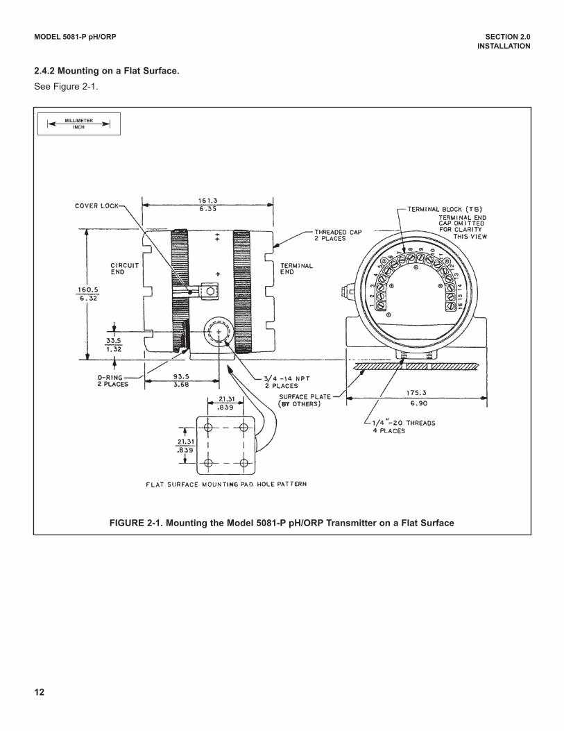
FIGURE 2-1. Mounting the Model 5081-P pH/ORP Transmitter on a Flat Surface
MILLIMETER
INCH
2.4.2 Mounting on a Flat Surface.
See Figure 2-1.
13
MODEL 5081-P pH/ORP SECTION 2.0
INSTALLATION
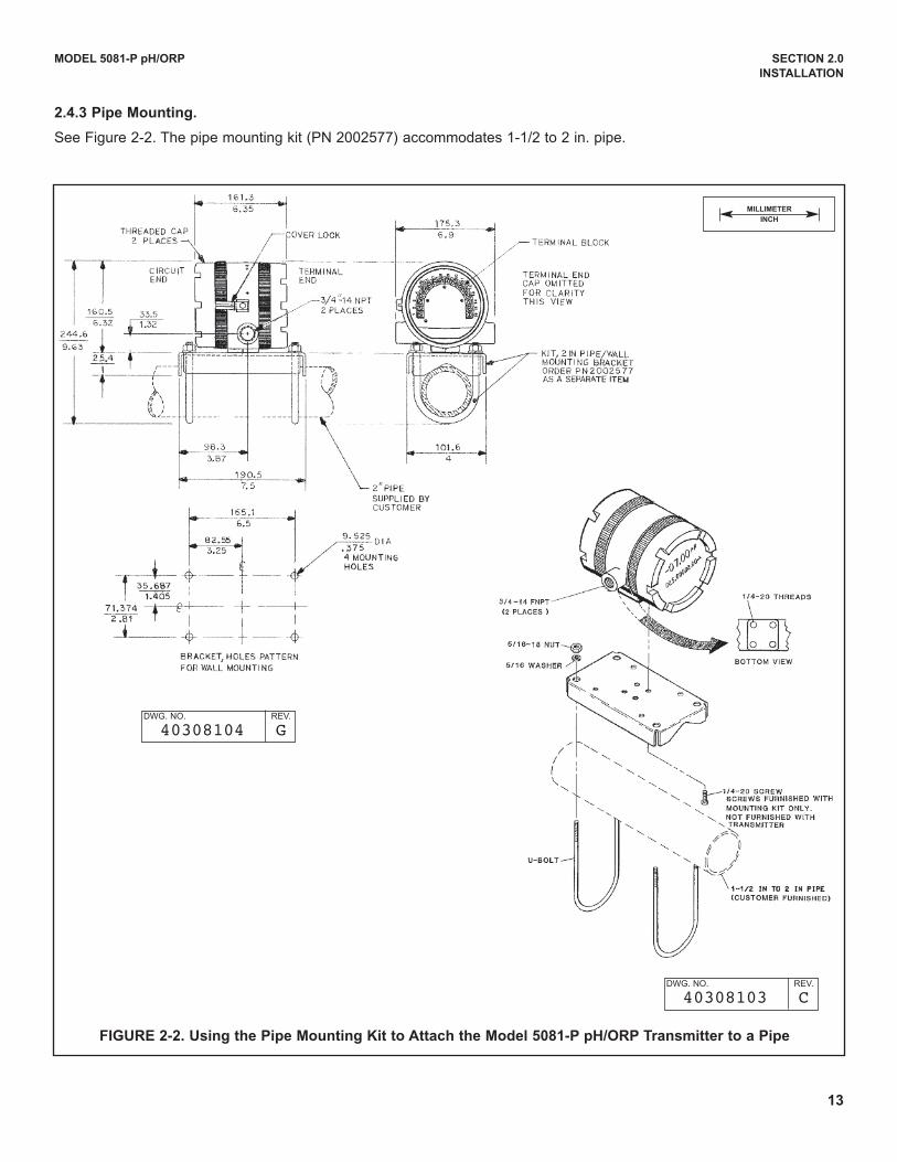
FIGURE 2-2. Using the Pipe Mounting Kit to Attach the Model 5081-P pH/ORP Transmitter to a Pipe
MILLIMETER
INCH
2.4.3 Pipe Mounting.
See Figure 2-2. The pipe mounting kit (PN 2002577) accommodates 1-1/2 to 2 in. pipe.
dWG. NO. REV.
40308104 G
dWG. NO. REV.
40308103 C
14
MODEL 5081-P pH/ORP SECTION 2.0
INSTALLATION
2.5 POwER SUPPLy/CURRENT LOOP — MODEL 5081-P-HT
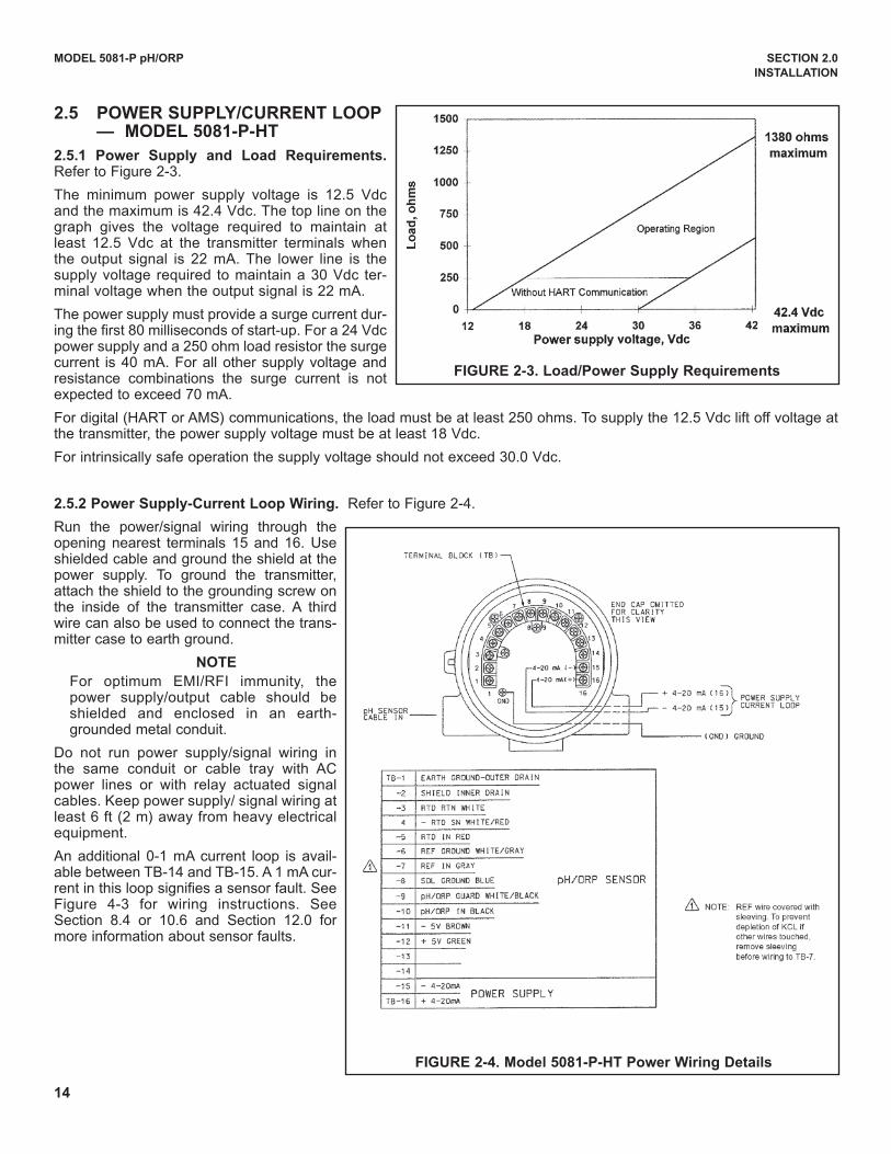
2.5.1 Power Supply and Load Requirements.Refer to Figure 2-3.
The minimum power supply voltage is 12.5 Vdcand the maximum is 42.4 Vdc. The top line on thegraph gives the voltage required to maintain atleast 12.5 Vdc at the transmitter terminals whenthe output signal is 22 mA. The lower line is thesupply voltage required to maintain a 30 Vdc ter-minal voltage when the output signal is 22 mA.
The power supply must provide a surge current dur-ing the first 80 milliseconds of start-up. For a 24 Vdcpower supply and a 250 ohm load resistor the surgecurrent is 40 mA. For all other supply voltage andresistance combinations the surge current is notexpected to exceed 70 mA.
For digital (HART or AMS) communications, the load must be at least 250 ohms. To supply the 12.5 Vdc lift off voltage atthe transmitter, the power supply voltage must be at least 18 Vdc.
For intrinsically safe operation the supply voltage should not exceed 30.0 Vdc.
2.5.2 Power Supply-Current Loop wiring. Refer to Figure 2-4.
Run the power/signal wiring through theopening nearest terminals 15 and 16. useshielded cable and ground the shield at thepower supply. To ground the transmitter,attach the shield to the grounding screw onthe inside of the transmitter case. A thirdwire can also be used to connect the trans-mitter case to earth ground.
NOTE
For optimum EMI/RFI immunity, thepower supply/output cable should beshielded and enclosed in an earth-grounded metal conduit.
do not run power supply/signal wiring inthe same conduit or cable tray with ACpower lines or with relay actuated signalcables. Keep power supply/ signal wiring atleast 6 ft (2 m) away from heavy electricalequipment.
An additional 0-1 mA current loop is avail-able between TB-14 and TB-15. A 1 mA cur-rent in this loop signifies a sensor fault. SeeFigure 4-3 for wiring instructions. SeeSection 8.4 or 10.6 and Section 12.0 formore information about sensor faults.
FIGURE 2-3. Load/Power Supply Requirements
FIGURE 2-4. Model 5081-P-HT Power wiring Details
15
MODEL 5081-P pH/ORP SECTION 2.0
INSTALLATION
2.6 POwER SUPPLy wIRING FOR MODEL 5081-P-FF
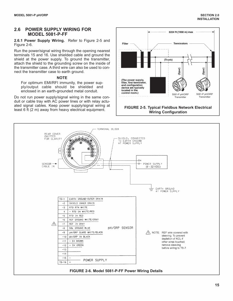
2.6.1 Power Supply wiring. Refer to Figure 2-5 andFigure 2-6.
Run the power/signal wiring through the opening nearestterminals 15 and 16. use shielded cable and ground theshield at the power supply. To ground the transmitter,attach the shield to the grounding screw on the inside ofthe transmitter case. A third wire can also be used to con-nect the transmitter case to earth ground.
NOTE
For optimum EMI/RFI immunity, the power sup-ply/output cable should be shielded andenclosed in an earth-grounded metal conduit.
do not run power supply/signal wiring in the same con-duit or cable tray with AC power lines or with relay actu-ated signal cables. Keep power supply/signal wiring atleast 6 ft (2 m) away from heavy electrical equipment.
FIGURE 2-5. Typical Fieldbus Network Electrical
wiring Configuration
FIGURE 2-6. Model 5081-P-FF Power wiring Details
5081-P pH/ORPTransmitter
5081-P pH/ORPTransmitter
16
MODEL 5081-P pH/ORP SECTION 3.0
wIRING
SECTION 3.0wIRING
3.1 GENERAL INFORMATION
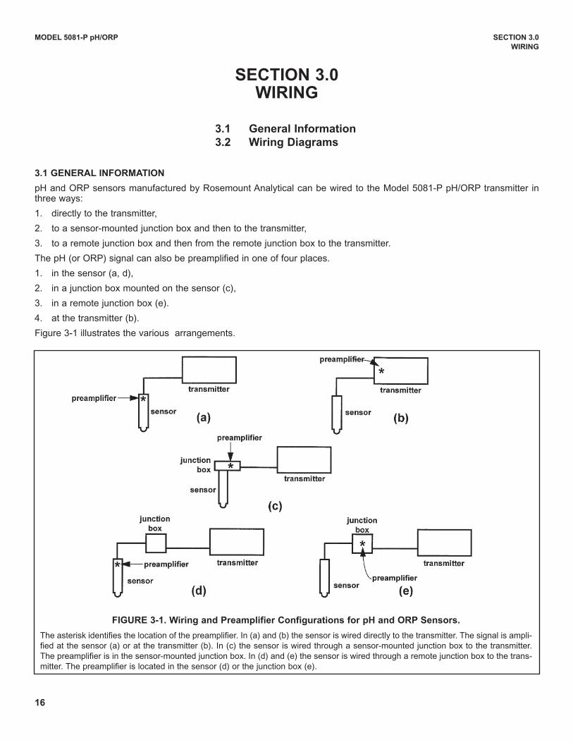
pH and ORP sensors manufactured by Rosemount Analytical can be wired to the Model 5081-P pH/ORP transmitter inthree ways:
1. directly to the transmitter,
2. to a sensor-mounted junction box and then to the transmitter,
3. to a remote junction box and then from the remote junction box to the transmitter.
The pH (or ORP) signal can also be preamplified in one of four places.
1. in the sensor (a, d),
2. in a junction box mounted on the sensor (c),
3. in a remote junction box (e).
4. at the transmitter (b).
Figure 3-1 illustrates the various arrangements.
3.1 General Information
3.2 wiring Diagrams
FIGURE 3-1. wiring and Preamplifier Configurations for pH and ORP Sensors.
The asterisk identifies the location of the preamplifier. In (a) and (b) the sensor is wired directly to the transmitter. The signal is ampli-fied at the sensor (a) or at the transmitter (b). In (c) the sensor is wired through a sensor-mounted junction box to the transmitter.The preamplifier is in the sensor-mounted junction box. In (d) and (e) the sensor is wired through a remote junction box to the trans-mitter. The preamplifier is located in the sensor (d) or the junction box (e).
17
MODEL 5081-P pH/ORP SECTION 3.0
wIRING
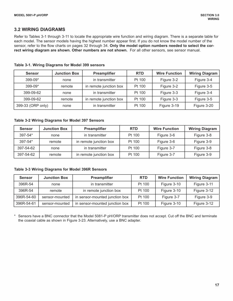
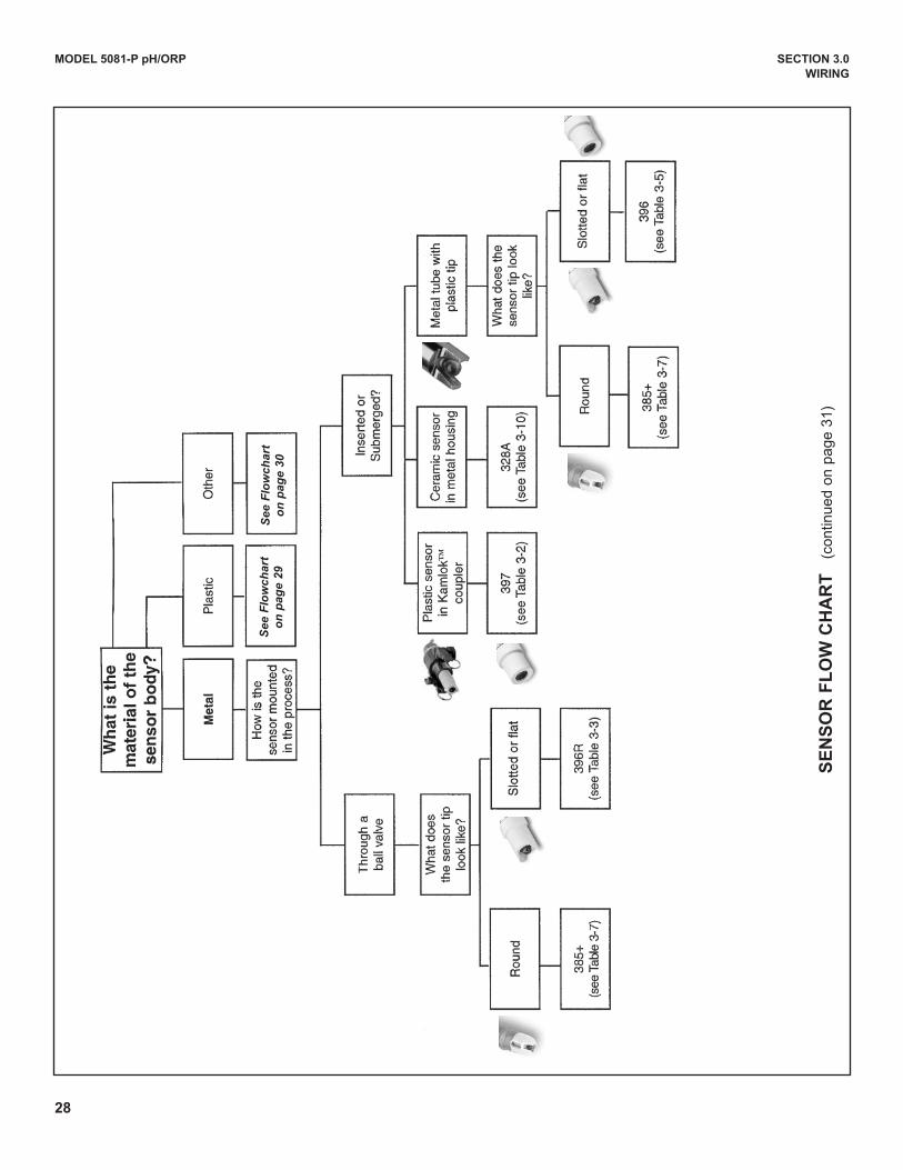
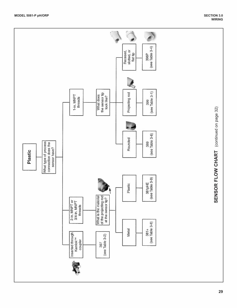
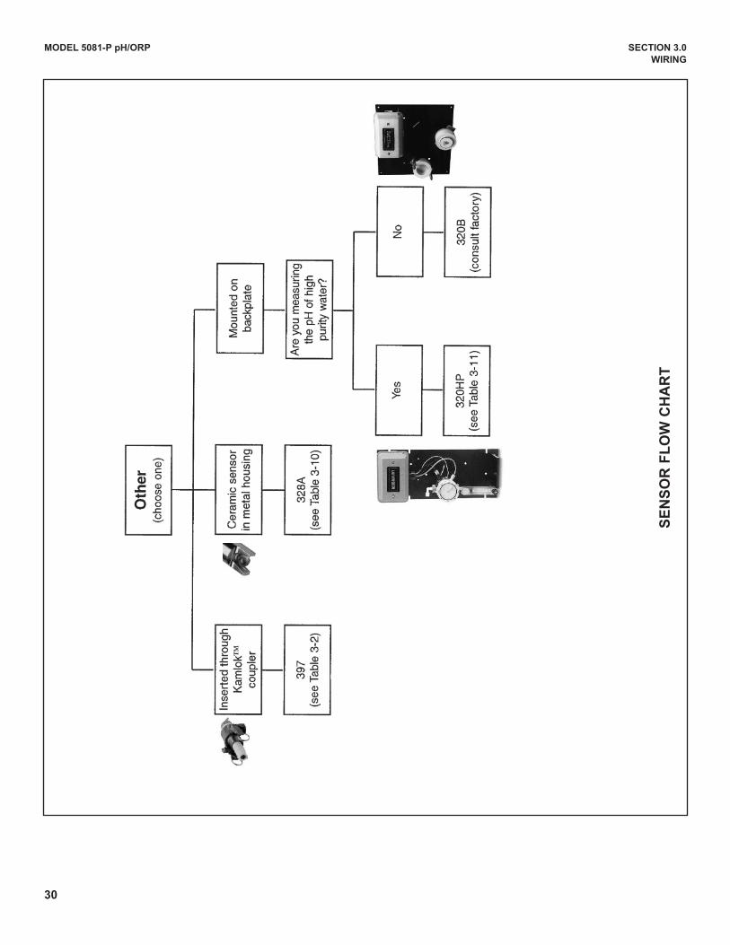
3.2 wIRING DIAGRAMS
Refer to Tables 3-1 through 3-11 to locate the appropriate wire function and wiring diagram. There is a separate table foreach model. The sensor models having the highest number appear first. If you do not know the model number of thesensor, refer to the flow charts on pages 32 through 34. Only the model option numbers needed to select the cor-
rect wiring diagram are shown. Other numbers are not shown. For all other sensors, see sensor manual.
Table 3-1. wiring Diagrams for Model 399 sensors
Sensor Junction Box Preamplifier RTD wire Function wiring Diagram
399-09* none in transmitter Pt 100 Figure 3-2 Figure 3-4
399-09* remote in remote junction box Pt 100 Figure 3-2 Figure 3-5
399-09-62 none in transmitter Pt 100 Figure 3-3 Figure 3-4
399-09-62 remote in remote junction box Pt 100 Figure 3-3 Figure 3-5
399-33 (ORP only) none in transmitter Pt 100 Figure 3-19 Figure 3-20
Table 3-2 wiring Diagrams for Model 397 Sensors
Sensor Junction Box Preamplifier RTD wire Function wiring Diagram
397-54* none in transmitter Pt 100 Figure 3-6 Figure 3-8
397-54* remote in remote junction box Pt 100 Figure 3-6 Figure 3-9
397-54-62 none in transmitter Pt 100 Figure 3-7 Figure 3-8
397-54-62 remote in remote junction box Pt 100 Figure 3-7 Figure 3-9
Table 3-3 wiring Diagrams for Model 396R Sensors
Sensor Junction Box Preamplifier RTD wire Function wiring Diagram
396R-54 none in transmitter Pt 100 Figure 3-10 Figure 3-11
396R-54 remote in remote junction box Pt 100 Figure 3-10 Figure 3-12
396R-54-60 sensor-mounted in sensor-mounted junction box Pt 100 Figure 3-7 Figure 3-9
396R-54-61 sensor-mounted in sensor-mounted junction box Pt 100 Figure 3-10 Figure 3-12
* Sensors have a BNC connector that the Model 5081-P pH/ORP transmitter does not accept. Cut off the BNC and terminatethe coaxial cable as shown in Figure 3-23. Alternatively, use a BNC adapter.
18
MODEL 5081-P pH/ORP SECTION 3.0
wIRING
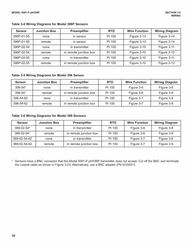
Table 3-4 wiring Diagrams for Model 396P Sensors
Sensor Junction Box Preamplifier RTD wire Function wiring Diagram
396P-01-55 none in sensor Pt 100 Figure 3-13 Figure 3-14
396P-01-55 remote in sensor Pt 100 Figure 3-13 Figure 3-14
396P-02-54 none in transmitter Pt 100 Figure 3-10 Figure 3-11
396P-02-54 remote in remote junction box Pt 100 Figure 3-10 Figure 3-12
396P-02-55 none in transmitter Pt 100 Figure 3-10 Figure 3-11
396P-02-55 remote in remote junction box Pt 100 Figure 3-10 Figure 3-12
Table 3-5 wiring Diagrams for Model 396 Sensor
Sensor Junction Box Preamplifier RTD wire Function wiring Diagram
396-54* none in transmitter Pt 100 Figure 3-6 Figure 3-8
396-54* remote in remote junction box Pt 100 Figure 3-6 Figure 3-9
396-54-62 none in transmitter Pt 100 Figure 3-7 Figure 3-8
396-54-62 remote in remote junction box Pt 100 Figure 3-7 Figure 3-9
Table 3-6 wiring Diagrams for Model 389 Sensors
Sensor Junction Box Preamplifier RTD wire Function wiring Diagram
389-02-54* none in transmitter Pt 100 Figure 3-6 Figure 3-8
389-02-54* remote in remote junction box Pt 100 Figure 3-6 Figure 3-9
389-02-54-62 none in transmitter Pt 100 Figure 3-7 Figure 3-8
389-02-54-62 remote in remote junction box Pt 100 Figure 3-7 Figure 3-9
* Sensors have a BNC connector that the Model 5081-P pH/ORP transmitter does not accept. Cut off the BNC and terminatethe coaxial cable as shown in Figure 3-23. Alternatively, use a BNC adapter (PN 9120531).
19
MODEL 5081-P pH/ORP SECTION 3.0
wIRING
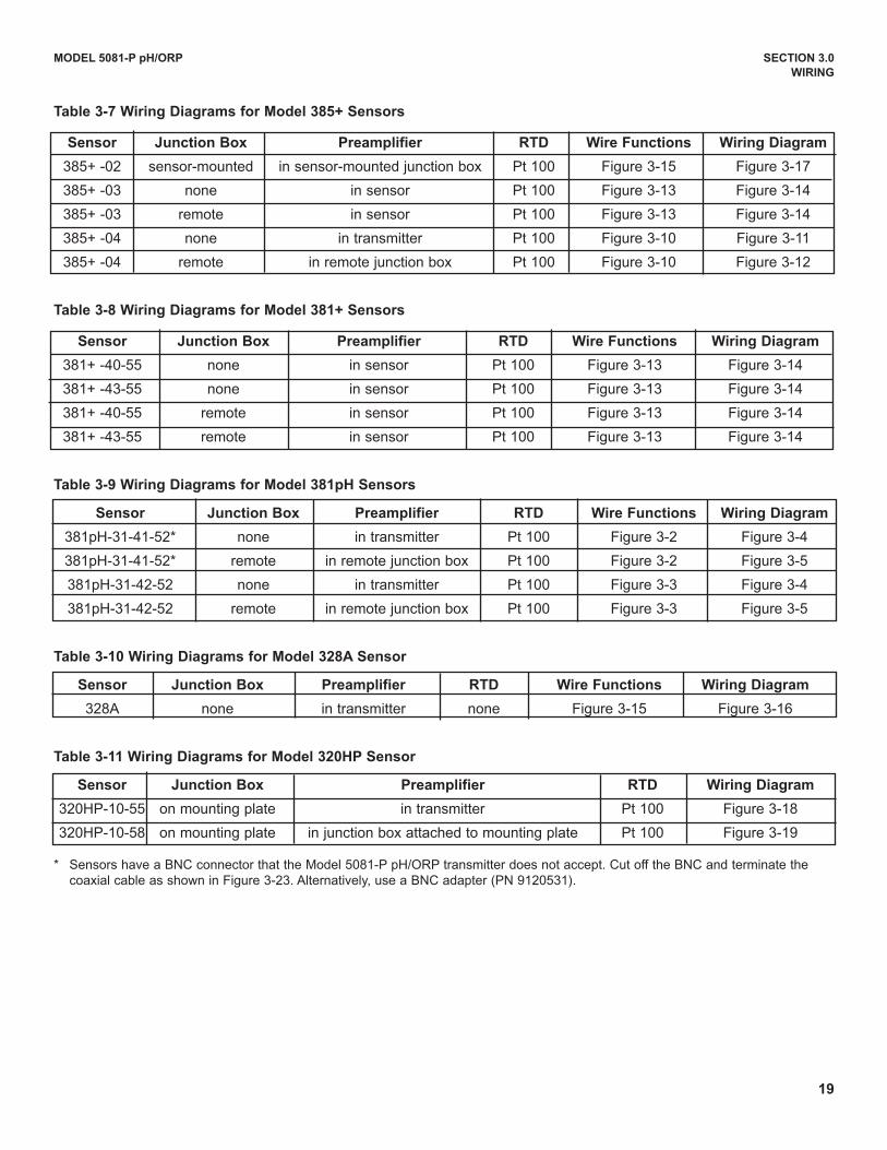
Table 3-7 wiring Diagrams for Model 385+ Sensors
Sensor Junction Box Preamplifier RTD wire Functions wiring Diagram
385+ -02 sensor-mounted in sensor-mounted junction box Pt 100 Figure 3-15 Figure 3-17
385+ -03 none in sensor Pt 100 Figure 3-13 Figure 3-14
385+ -03 remote in sensor Pt 100 Figure 3-13 Figure 3-14
385+ -04 none in transmitter Pt 100 Figure 3-10 Figure 3-11
385+ -04 remote in remote junction box Pt 100 Figure 3-10 Figure 3-12
Table 3-8 wiring Diagrams for Model 381+ Sensors
Sensor Junction Box Preamplifier RTD wire Functions wiring Diagram
381+ -40-55 none in sensor Pt 100 Figure 3-13 Figure 3-14
381+ -43-55 none in sensor Pt 100 Figure 3-13 Figure 3-14
381+ -40-55 remote in sensor Pt 100 Figure 3-13 Figure 3-14
381+ -43-55 remote in sensor Pt 100 Figure 3-13 Figure 3-14
Table 3-9 wiring Diagrams for Model 381pH Sensors
Sensor Junction Box Preamplifier RTD wire Functions wiring Diagram
381pH-31-41-52* none in transmitter Pt 100 Figure 3-2 Figure 3-4
381pH-31-41-52* remote in remote junction box Pt 100 Figure 3-2 Figure 3-5
381pH-31-42-52 none in transmitter Pt 100 Figure 3-3 Figure 3-4
381pH-31-42-52 remote in remote junction box Pt 100 Figure 3-3 Figure 3-5
Table 3-10 wiring Diagrams for Model 328A Sensor
Sensor Junction Box Preamplifier RTD wire Functions wiring Diagram
328A none in transmitter none Figure 3-15 Figure 3-16
Table 3-11 wiring Diagrams for Model 320HP Sensor
Sensor Junction Box Preamplifier RTD wiring Diagram
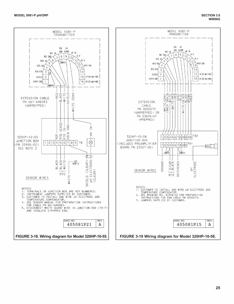
320HP-10-55 on mounting plate in transmitter Pt 100 Figure 3-18
320HP-10-58 on mounting plate in junction box attached to mounting plate Pt 100 Figure 3-19
* Sensors have a BNC connector that the Model 5081-P pH/ORP transmitter does not accept. Cut off the BNC and terminate thecoaxial cable as shown in Figure 3-23. Alternatively, use a BNC adapter (PN 9120531).
20
MODEL 5081-P pH/ORP SECTION 3.0
wIRING
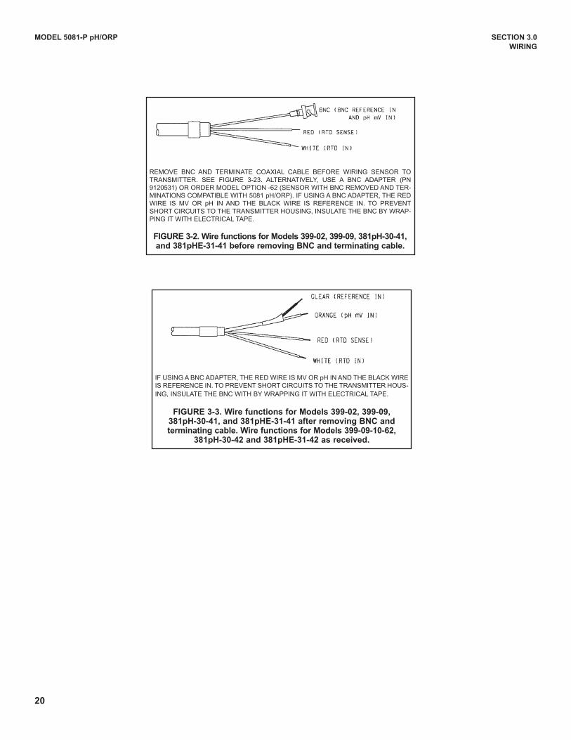
REMOVE BNC ANd TERMINATE COAXIAL CABLE BEFORE WIRING SENSOR TOTRANSMITTER. SEE FIGuRE 3-23. ALTERNATIVELY, uSE A BNC AdAPTER (PN9120531) OR ORdER MOdEL OPTION -62 (SENSOR WITH BNC REMOVEd ANd TER-MINATIONS COMPATIBLE WITH 5081 pH/ORP). IF uSING A BNC AdAPTER, THE REdWIRE IS MV OR pH IN ANd THE BLACK WIRE IS REFERENCE IN. TO PREVENTSHORT CIRCuITS TO THE TRANSMITTER HOuSING, INSuLATE THE BNC BY WRAP-PING IT WITH ELECTRICAL TAPE.
FIGURE 3-2. wire functions for Models 399-02, 399-09, 381pH-30-41,and 381pHE-31-41 before removing BNC and terminating cable.
IF uSING A BNC AdAPTER, THE REd WIRE IS MV OR pH IN ANd THE BLACK WIREIS REFERENCE IN. TO PREVENT SHORT CIRCuITS TO THE TRANSMITTER HOuS-ING, INSuLATE THE BNC WITH BY WRAPPING IT WITH ELECTRICAL TAPE.
FIGURE 3-3. wire functions for Models 399-02, 399-09,381pH-30-41, and 381pHE-31-41 after removing BNC andterminating cable. wire functions for Models 399-09-10-62,
381pH-30-42 and 381pHE-31-42 as received.
21
MODEL 5081-P pH/ORP SECTION 3.0
wIRING
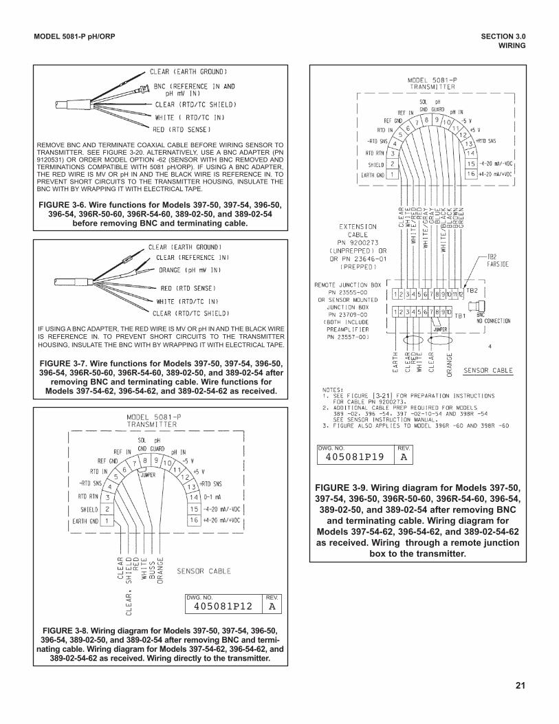
REMOVE BNC ANd TERMINATE COAXIAL CABLE BEFORE WIRING SENSOR TOTRANSMITTER. SEE FIGuRE 3-20. ALTERNATIVELY, uSE A BNC AdAPTER (PN9120531) OR ORdER MOdEL OPTION -62 (SENSOR WITH BNC REMOVEd ANdTERMINATIONS COMPATIBLE WITH 5081 pH/ORP). IF uSING A BNC AdAPTER,THE REd WIRE IS MV OR pH IN ANd THE BLACK WIRE IS REFERENCE IN. TOPREVENT SHORT CIRCuITS TO THE TRANSMITTER HOuSING, INSuLATE THEBNC WITH BY WRAPPING IT WITH ELECTRICAL TAPE.
FIGURE 3-6. wire functions for Models 397-50, 397-54, 396-50,396-54, 396R-50-60, 396R-54-60, 389-02-50, and 389-02-54
before removing BNC and terminating cable.
IF uSING A BNC AdAPTER, THE REd WIRE IS MV OR pH IN ANd THE BLACK WIREIS REFERENCE IN. TO PREVENT SHORT CIRCuITS TO THE TRANSMITTERHOuSING, INSuLATE THE BNC WITH BY WRAPPING IT WITH ELECTRICAL TAPE.
FIGURE 3-7. wire functions for Models 397-50, 397-54, 396-50,396-54, 396R-50-60, 396R-54-60, 389-02-50, and 389-02-54 after
removing BNC and terminating cable. wire functions forModels 397-54-62, 396-54-62, and 389-02-54-62 as received.
FIGURE 3-8. wiring diagram for Models 397-50, 397-54, 396-50,396-54, 389-02-50, and 389-02-54 after removing BNC and termi-
nating cable. wiring diagram for Models 397-54-62, 396-54-62, and389-02-54-62 as received. wiring directly to the transmitter.
FIGURE 3-9. wiring diagram for Models 397-50,
397-54, 396-50, 396R-50-60, 396R-54-60, 396-54,
389-02-50, and 389-02-54 after removing BNC
and terminating cable. wiring diagram for
Models 397-54-62, 396-54-62, and 389-02-54-62
as received. wiring through a remote junction
box to the transmitter.
4
dWG. NO. REV.
405081P12 A
dWG. NO. REV.
405081P19 A
22
MODEL 5081-P pH/ORP SECTION 3.0
wIRING
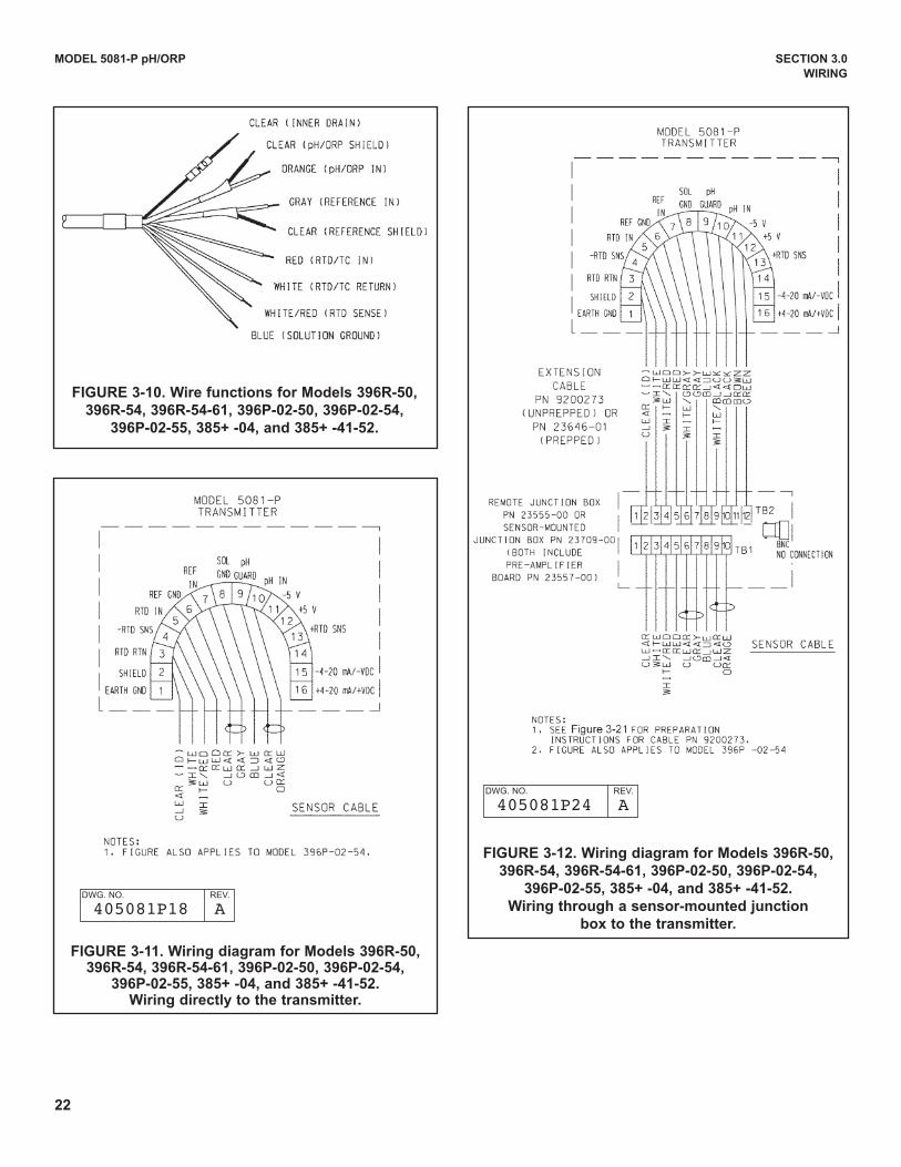
FIGURE 3-10. wire functions for Models 396R-50,
396R-54, 396R-54-61, 396P-02-50, 396P-02-54,
396P-02-55, 385+ -04, and 385+ -41-52.
FIGURE 3-11. wiring diagram for Models 396R-50,396R-54, 396R-54-61, 396P-02-50, 396P-02-54,
396P-02-55, 385+ -04, and 385+ -41-52.wiring directly to the transmitter.
FIGURE 3-12. wiring diagram for Models 396R-50,
396R-54, 396R-54-61, 396P-02-50, 396P-02-54,
396P-02-55, 385+ -04, and 385+ -41-52.
wiring through a sensor-mounted junction
box to the transmitter.
dWG. NO. REV.
405081P18 A
dWG. NO. REV.
405081P24 A
23
MODEL 5081-P pH/ORP SECTION 3.0
wIRING
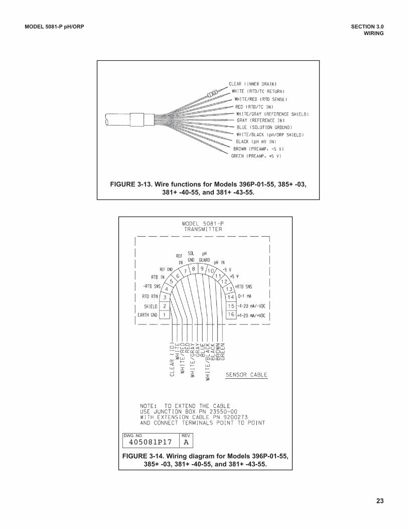
FIGURE 3-13. wire functions for Models 396P-01-55, 385+ -03,
381+ -40-55, and 381+ -43-55.
FIGURE 3-14. wiring diagram for Models 396P-01-55,
385+ -03, 381+ -40-55, and 381+ -43-55.
dWG. NO. REV.
405081P17 A
24
MODEL 5081-P pH/ORP SECTION 3.0
wIRING
FIGURE 3-15. wire functions for Model 328A-07.
FIGURE 3-16. wiring diagram for Models 328A and
382+-02.
dWG. NO. REV.
405081P20 A
dWG. NO. REV.
405081P20 A
FIGURE 3-17. wiring diagram for Model 385+-02.
dWG. NO. REV.
45081P25 A
25
MODEL 5081-P pH/ORP SECTION 3.0
wIRING
FIGURE 3-18. wiring diagram for Model 320HP-10-55. FIGURE 3-19 wiring diagram for Model 320HP-10-58.
dWG. NO. REV.
405081P21 A
dWG. NO. REV.
405081P15 A
26
MODEL 5081-P pH/ORP SECTION 3.0
wIRING
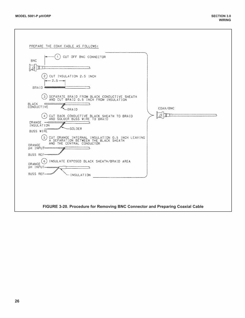
FIGURE 3-20. Procedure for Removing BNC Connector and Preparing Coaxial Cable
27
MODEL 5081-P pH/ORP SECTION 3.0
wIRING
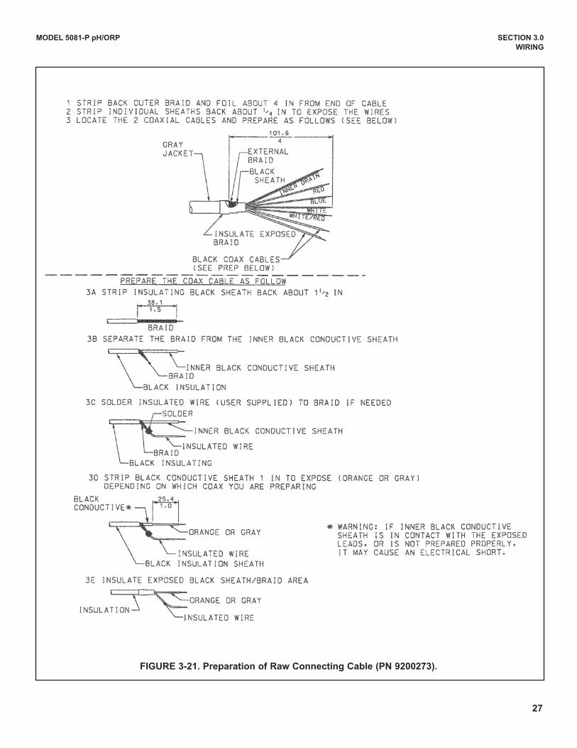
FIGURE 3-21. Preparation of Raw Connecting Cable (PN 9200273).
28
MODEL 5081-P pH/ORP SECTION 3.0
wIRING
SE
NS
OR
FL
Ow
CH
AR
T
(co
ntin
ue
d o
n p
ag
e 3
1)
Se
e F
low
ch
art
on
pa
ge
30
Se
e F
low
ch
art
on
pa
ge
29
29
MODEL 5081-P pH/ORP SECTION 3.0
wIRING
SE
NS
OR
FL
Ow
CH
AR
T(c
on
tinu
ed
on
pa
ge
32
)
30
MODEL 5081-P pH/ORP SECTION 3.0
wIRING
SE
NS
OR
FL
Ow
CH
AR
T
MODEL 5081-P pH/ORP SECTION 4.0
INTRINSICALLy SAFE & ExPLOSION PROOF
SECTION 4.0INTRINSICALLy SAFE & ExPLOSION PROOF
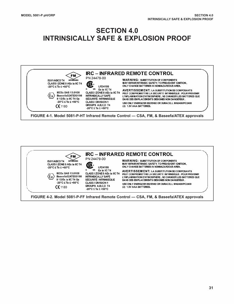
FIGURE 4-1. Model 5081-P-HT Infrared Remote Control — CSA, FM, & Baseefa/ATEx approvals
FIGURE 4-2. Model 5081-P-FF Infrared Remote Control — CSA, FM, & Baseefa/ATEx approvals
31
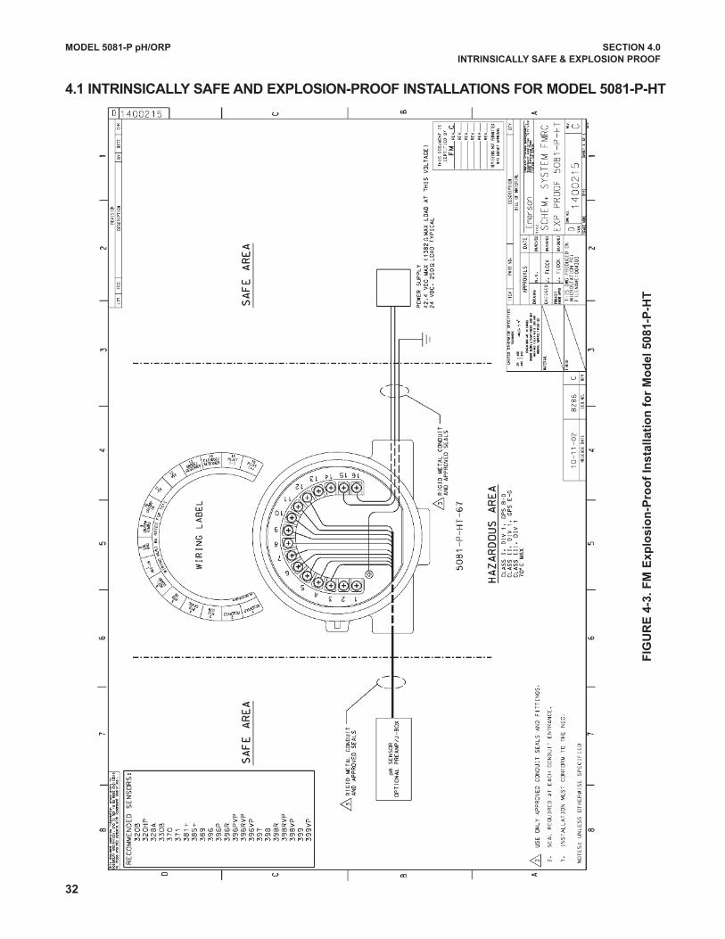
FIG
UR
E 4
-3.
FM
Ex
plo
sio
n-P
roo
f In
sta
lla
tio
n f
or
Mo
de
l 5
08
1-P
-HT
MODEL 5081-P pH/ORP SECTION 4.0
INTRINSICALLy SAFE & ExPLOSION PROOF
4.1 INTRINSICALLy SAFE AND ExPLOSION-PROOF INSTALLATIONS FOR MODEL 5081-P-HT
32
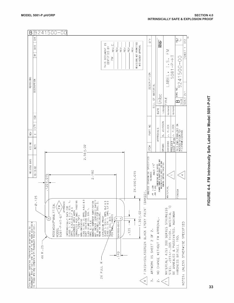
FIG
UR
E 4
-4.
FM
In
trin
sic
ally
Sa
fe L
ab
el
for
Mo
de
l 5
08
1-P
-HT
MODEL 5081-P pH/ORP SECTION 4.0
INTRINSICALLy SAFE & ExPLOSION PROOF
33
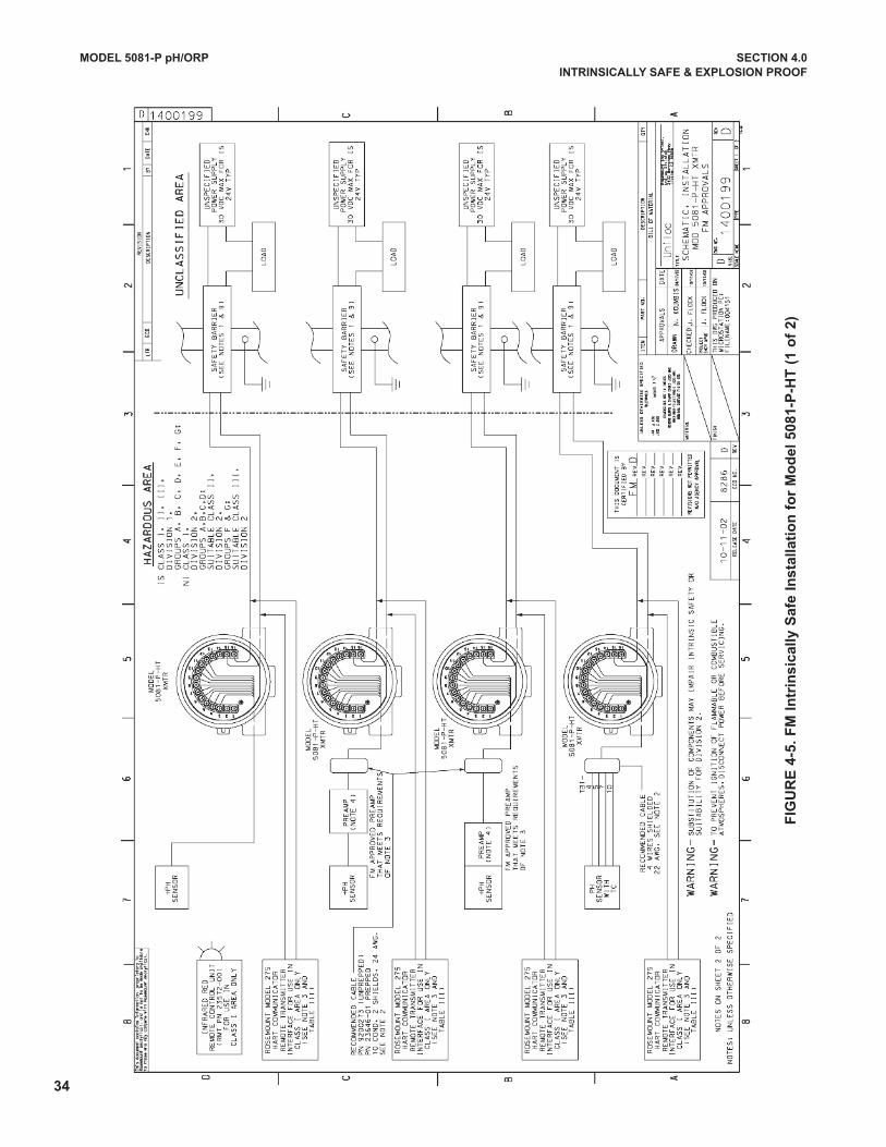
34
FIG
UR
E 4
-5.
FM
In
trin
sic
ally
Sa
fe I
ns
talla
tio
n f
or
Mo
de
l 5
08
1-P
-HT
(1
of
2)
MODEL 5081-P pH/ORP SECTION 4.0
INTRINSICALLy SAFE & ExPLOSION PROOF
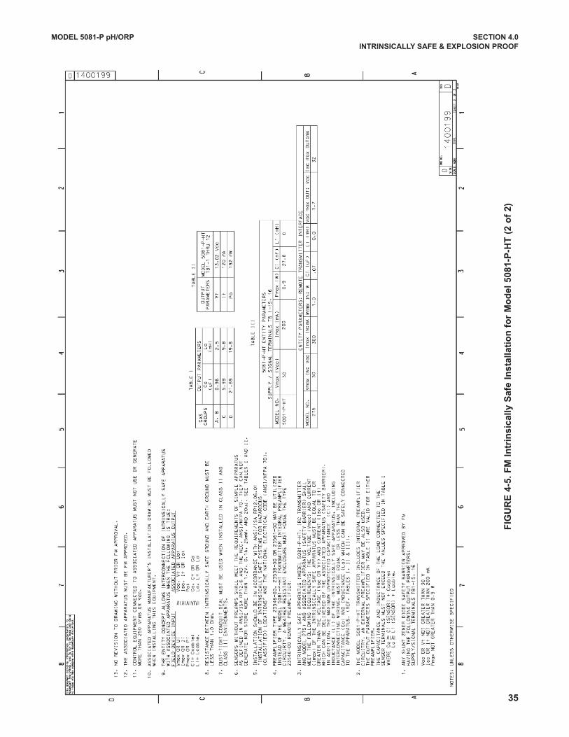
FIG
UR
E 4
-5.
FM
In
trin
sic
ally
Sa
fe I
ns
talla
tio
n f
or
Mo
de
l 5
08
1-P
-HT
(2
of
2)
MODEL 5081-P pH/ORP SECTION 4.0
INTRINSICALLy SAFE & ExPLOSION PROOF
35

36
FIG
UR
E 4
-6.
CS
A I
ntr
ins
ica
lly
Sa
fe L
ab
el
for
Mo
de
l 5
08
1-P
-HT
MODEL 5081-P pH/ORP SECTION 4.0
INTRINSICALLy SAFE & ExPLOSION PROOF
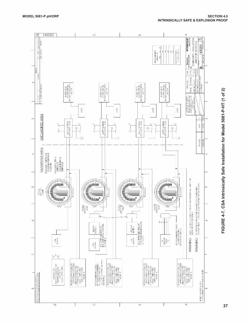
FIG
UR
E 4
-7.
CS
A I
ntr
ins
ica
lly
Sa
fe I
ns
talla
tio
n f
or
Mo
de
l 5
08
1-P
-HT
(1
of
2)
MODEL 5081-P pH/ORP SECTION 4.0
INTRINSICALLy SAFE & ExPLOSION PROOF
37
38
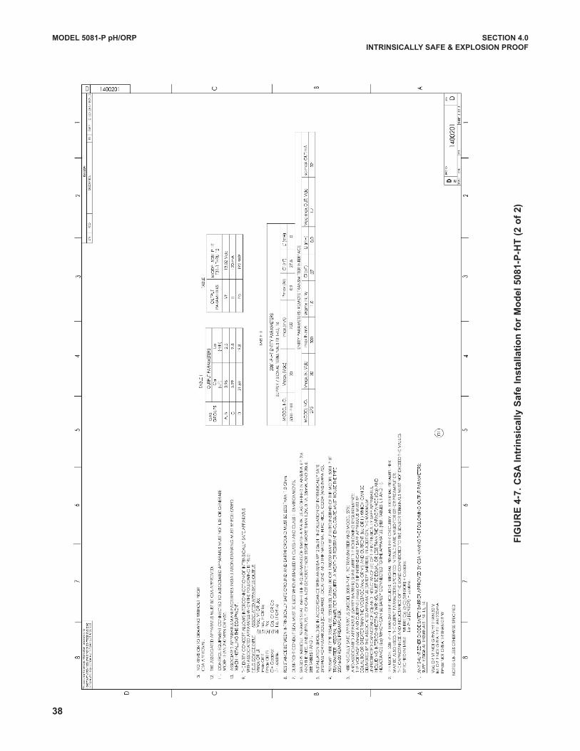
FIG
UR
E 4
-7.
CS
A I
ntr
ins
ica
lly
Sa
fe I
ns
talla
tio
n f
or
Mo
de
l 5
08
1-P
-HT
(2
of
2)
MODEL 5081-P pH/ORP SECTION 4.0
INTRINSICALLy SAFE & ExPLOSION PROOF
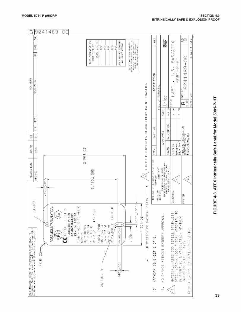
FIG
UR
E 4
-8. A
TE
x I
ntr
ins
ica
lly
Sa
fe L
ab
el
for
Mo
de
l 5
08
1-P
-HT
MODEL 5081-P pH/ORP SECTION 4.0
INTRINSICALLy SAFE & ExPLOSION PROOF
39
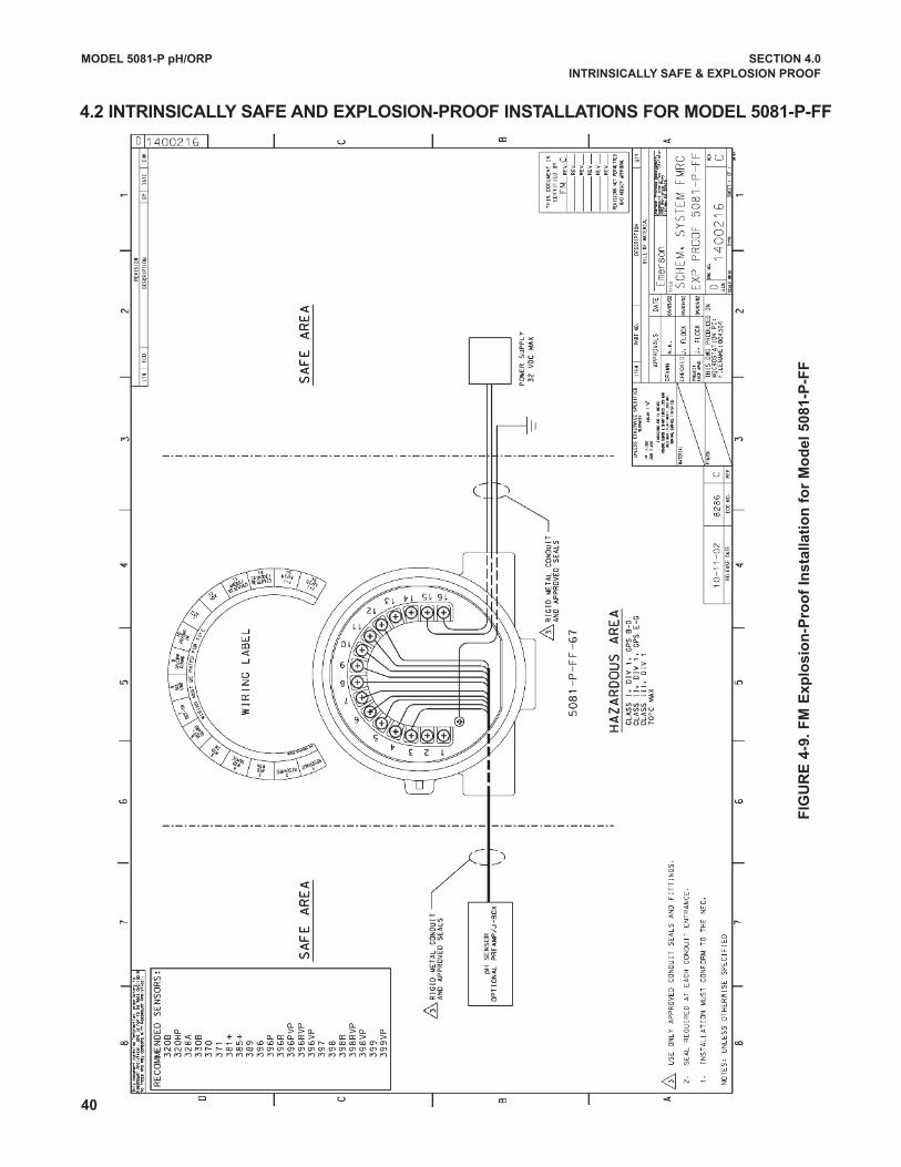
40
FIG
UR
E 4
-9.
FM
Ex
plo
sio
n-P
roo
f In
sta
lla
tio
n f
or
Mo
de
l 5
08
1-P
-FF
MODEL 5081-P pH/ORP SECTION 4.0
INTRINSICALLy SAFE & ExPLOSION PROOF
4.2 INTRINSICALLy SAFE AND ExPLOSION-PROOF INSTALLATIONS FOR MODEL 5081-P-FF
FIG
UR
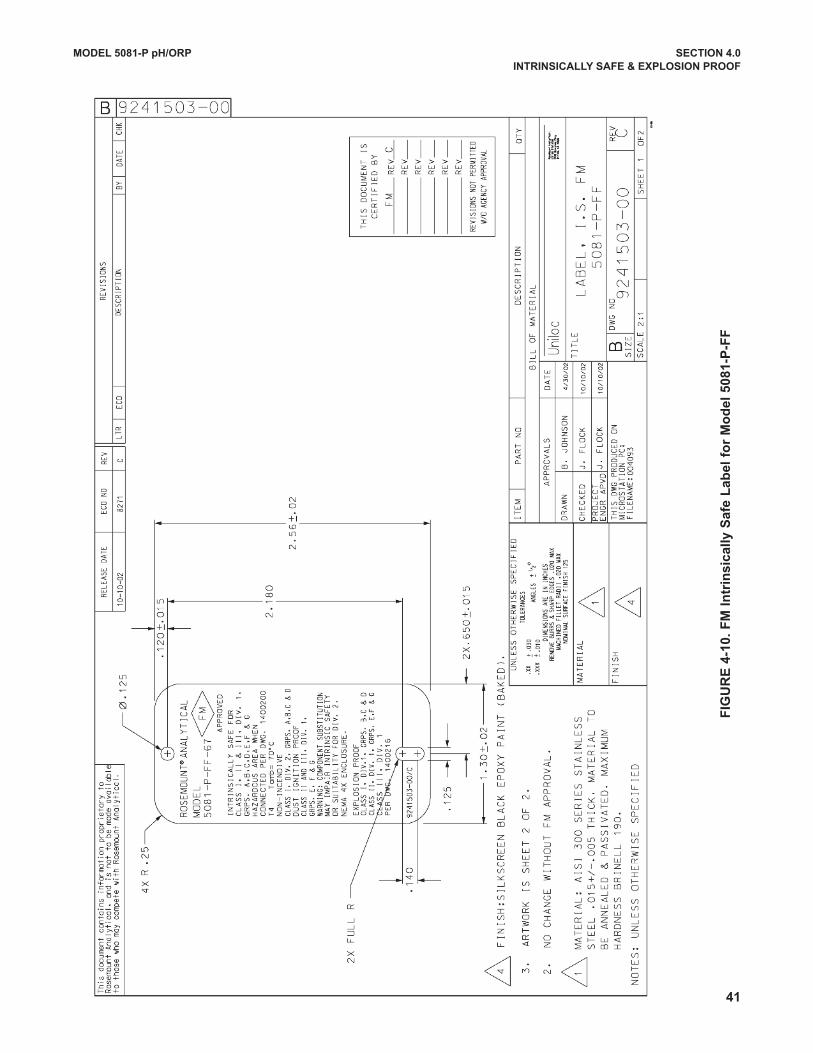
E 4
-10
. F
M I
ntr
ins
ica
lly
Sa
fe L
ab
el
for
Mo
de
l 5
08
1-P
-FF
MODEL 5081-P pH/ORP SECTION 4.0
INTRINSICALLy SAFE & ExPLOSION PROOF
41
42
FIG
UR
E 4
FIG
UR
E 4
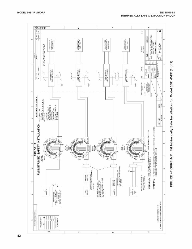
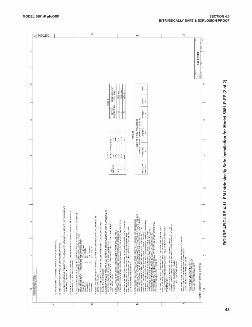
-11
. F
M I
ntr
ins
ica
lly
Sa
fe I
ns
talla
tio
n f
or
Mo
de
l 5
08
1-P
-FF
(1
of
2)
MODEL 5081-P pH/ORP SECTION 4.0
INTRINSICALLy SAFE & ExPLOSION PROOF
FIG
UR
E 4
FIG
UR
E 4
-11
. F
M I
ntr
ins
ica
lly
Sa
fe I
ns
talla
tio
n f
or
Mo
de
l 5
08
1-P
-FF
(2
of
2)
MODEL 5081-P pH/ORP SECTION 4.0
INTRINSICALLy SAFE & ExPLOSION PROOF
43
44
FIG
UR
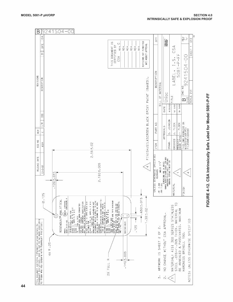
E 4
-12
. C
SA
In
trin
sic
ally
Sa
fe L
ab
el
for
Mo
de
l 5
08
1-P
-FF
MODEL 5081-P pH/ORP SECTION 4.0
INTRINSICALLy SAFE & ExPLOSION PROOF
FIG
UR
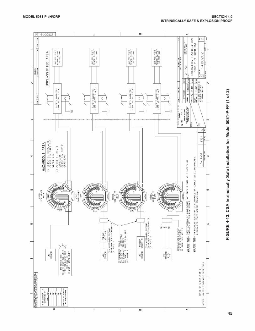
E 4
-13
. C
SA
In
trin
sic
ally
Sa
fe I
ns
talla
tio
n f
or
Mo
de
l 5
08
1-P
-FF
(1
of
2)
MODEL 5081-P pH/ORP SECTION 4.0
INTRINSICALLy SAFE & ExPLOSION PROOF
45
46
FIG
UR
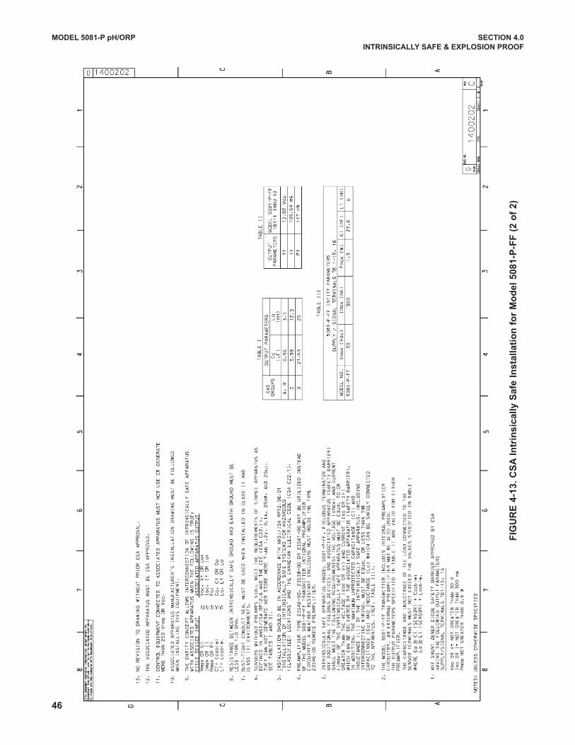
E 4
-13
. C
SA
In
trin
sic
ally
Sa
fe I
ns
talla
tio
n f
or
Mo
de
l 5
08
1-P
-FF
(2
of
2)
MODEL 5081-P pH/ORP SECTION 4.0
INTRINSICALLy SAFE & ExPLOSION PROOF
FIG
UR
E 4
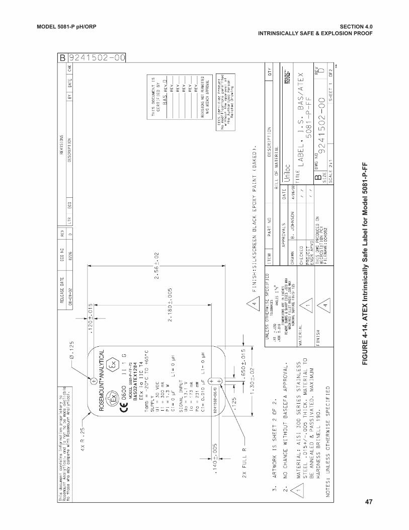
-14
. A
TE
x I
ntr
ins
ica
lly
Sa
fe L
ab
el
for
Mo
de
l 5
08
1-P
-FF
MODEL 5081-P pH/ORP SECTION 4.0
INTRINSICALLy SAFE & ExPLOSION PROOF
47
48
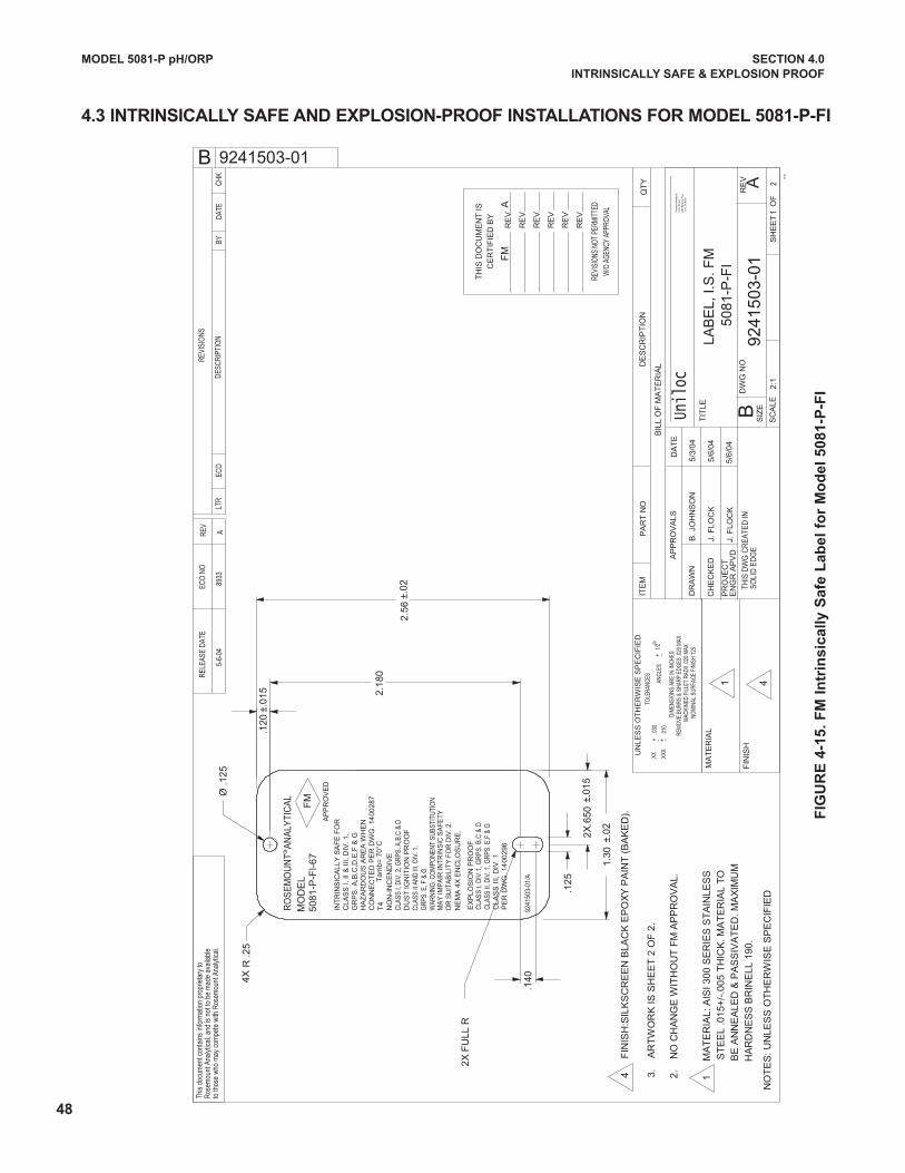
MODEL 5081-P pH/ORP SECTION 4.0
INTRINSICALLy SAFE & ExPLOSION PROOF
W/O
AGE
NCY
APPR
OVAL
REVI
SION
S NO
T PE
RMIT
TED
RE
V
RE
V
RE
V
RE
V
RE
V
RE
V
CE
RT
IFIE
D B
Y
TH
IS D
OC
UM
EN
T IS
°CT
am
b=
70
FM
A
5/6/
04J.
FLO
CK
5/6/
04J.
FLO
CK
.140
.125
1.30
±.022X
.650
±.01
5
2.56
±.02
2.18
0
.120
±.01
5
Ø .1
25
R .2
5
OR
SU
ITA
BIL
ITY
FO
R D
IV. 2
.M
AY
IMP
AIR
INTR
INS
IC S
AFE
TY
5081
-P-F
I-67
MO
DE
L
GR
PS. E
, F &
G
GR
PS
. A,B
,C,D
,E,F
& G
R
CLA
SS II
AN
D II
I, D
IV. 1
,
CLA
SS
I, I
I &
III
, DIV
. 1,
HA
ZA
RD
OU
S A
RE
A W
HE
N
INT
RIN
SIC
ALL
Y S
AF
E F
OR
CO
NN
EC
TE
D P
ER
DW
G. 1
400
287
DU
ST
IGN
ITIO
N P
RO
OF
AP
PR
OV
ED
FM
NE
MA
4X
EN
CLO
SU
RE
.
WAR
NIN
G: C
OM
PON
ENT
SUBS
TITU
TIO
N
CLA
SS I,
DIV
. 2, G
RPS
. A,B
,C &
DN
ON
-IN
CE
ND
IVE
T4RO
SE
MO
UN
T A
NA
LYTI
CA
L
PE
R D
WG
. 14
002
96C
LAS
S I
II, D
IV. 1
CLA
SS II
, DIV
. 1, G
RPS
. E,F
& G
CLA
SS
I, D
IV.1
, GR
PS. B
,C &
DE
XP
LOS
ION
PR
OO
F
4
4
FIN
ISH
:SIL
KS
CR
EE
N B
LAC
K E
PO
XY
PA
INT
(B
AK
ED
).
508
1-P
-FI
HA
RD
NE
SS
BR
INE
LL 1
90.
BE
AN
NE
ALE
D &
PA
SS
IVA
TE
D. M
AX
IMU
MS
TE
EL
.015
+/-
.005
TH
ICK
. MA
TE
RIA
L T
O
1
MA
TE
RIA
L: A
ISI 3
00 S
ER
IES
ST
AIN
LES
S
2X F
ULL
R
4X
2.
NO
CH
AN
GE
WIT
HO
UT
FM
AP
PR
OV
AL.
3.
AR
TW
OR
K IS
SH
EE
T 2
OF
2.
1
Unil
ocIrv
ine,
CA
9260
624
00 B
arra
nca
Pkwy
Unilo
c Di
vision
Rose
mou
nt A
nalyt
ical,
5/3/
04NO
MIN
AL S
URFA
CE F
INIS
H 12
5
5-6-
04
89
33A
9241503-01
B. J
OH
NS
ON
2:1
L
AB
EL,
I.S
. FM
A92
415
03-0
11
2S
HE
ET
O
F10
-96
TOLE
RANC
ES
UN
LES
S O
TH
ER
WIS
E S
PE
CIF
IED
ANG
LES
+ 1
/2-
.030
.XX
.XXX
.010
+-+
AP
PR
OV
ALS
TIT
LE
B
DA
TE
SOLI
D E
DG
ETH
IS D
WG
CR
EATE
D IN
B
to th
ose
who
may
com
pete
with
Ros
emou
nt A
naly
tical
.Ro
sem
ount
Ana
lytic
al, a
nd is
not
to b
e m
ade
avai
labl
eTh
is do
cum
ent c
onta
ins
info
rmat
ion
prop
rieta
ry to
CHK
DATE
BYDE
SCRI
PTIO
N
REVI
SIO
NS
ECO
LTR
RELE
ASE
DATE
ECO
NO
REV
NO
TE
S: U
NLE
SS
OT
HE
RW
ISE
SP
EC
IFIE
D
EN
GR
AP
VD
PR
OJE
CT
CH
EC
KE
D
DR
AW
N
FIN
ISH
MA
TE
RIA
L
BIL
L O
F M
AT
ER
IAL
DW
G N
OR
EV
SIZ
E
SC
ALE
QT
YD
ES
CR
IPT
ION
PA
RT
NO
ITE
M
-
MAC
HINE
D FI
LLET
RAD
II .0
20 M
AXRE
MO
VE B
URRS
& S
HARP
EDG
ES .0
20 M
AXDI
MEN
SIO
NS A
RE IN
INCH
ES
9241
503-
01/A
FIG
UR
E 4
-15
. F
M I
ntr
ins
ica
lly
Sa
fe L
ab
el
for
Mo
de
l 5
08
1-P
-FI
4.3 INTRINSICALLy SAFE AND ExPLOSION-PROOF INSTALLATIONS FOR MODEL 5081-P-FI
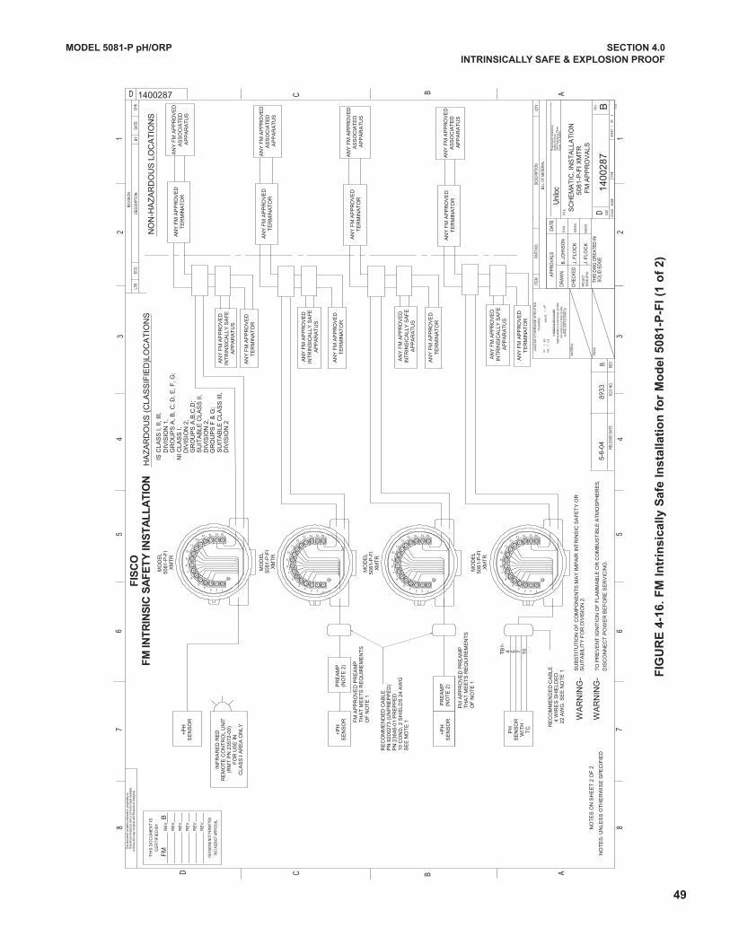
49
FIG
UR
E 4
-16
. F
M I
ntr
ins
ica
lly
Sa
fe I
ns
talla
tio
n f
or
Mo
de
l 5
08
1-P
-FI
(1 o
f 2
)
BF
M
AN
Y F
M A
PP
RO
VE
DA
SS
OC
IAT
ED
AP
PA
RA
TU
S
AN
Y F
M A
PP
RO
VE
DA
SS
OC
IAT
ED
AP
PA
RA
TU
S
AN
Y F
M A
PP
RO
VE
DA
SS
OC
IAT
ED
AP
PA
RA
TU
S
AN
Y F
M A
PP
RO
VE
DT
ER
MIN
AT
OR
AN
Y F
M A
PP
RO
VE
DIN
TR
INS
ICA
LLY
SA
FE
AP
PA
RA
TU
S
AN
Y F
M A
PP
RO
VE
DT
ER
MIN
AT
OR
AN
Y F
M A
PP
RO
VE
DT
ER
MIN
AT
OR
AN
Y F
M A
PP
RO
VE
DIN
TR
INS
ICA
LLY
SA
FE
AP
PA
RA
TU
S
AN
Y F
M A
PP
RO
VE
DT
ER
MIN
AT
OR
AN
Y F
M A
PP
RO
VE
DT
ER
MIN
AT
OR
AN
Y F
M A
PP
RO
VE
DIN
TR
INS
ICA
LLY
SA
FE
AP
PA
RA
TU
S
AN
Y F
M A
PP
RO
VE
DT
ER
MIN
AT
OR
AN
Y F
M A
PP
RO
VE
DT
ER
MIN
AT
OR
AN
Y F
M A
PP
RO
VE
DIN
TR
INS
ICA
LLY
SA
FE
AP
PA
RA
TU
S
AN
Y F
M A
PP
RO
VE
DT
ER
MIN
AT
OR
NO
N-H
AZ
AR
DO
US
LO
CA
TIO
NS
AN
Y F
M A
PP
RO
VE
DA
SS
OC
IAT
ED
AP
PA
RA
TU
S
G
RO
UP
S F
& G
;
DIV
ISIO
N 2
,
SU
ITA
BLE
CLA
SS
II,
G
RO
UP
S A
,B,C
,D;
D
IVIS
ION
2,
NI C
LAS
S I,
G
RO
UP
S A
, B, C
, D, E
, F, G
;
DIV
ISIO
N 1
,IS
CLA
SS
I, II
, III,
D
IVIS
ION
2
SU
ITA
BLE
CLA
SS
III,
HA
ZA
RD
OU
S (
CLA
SS
IFIE
D)L
OC
AT
ION
S
5/6/
04J.
FLO
CK
FIS
CO
FM
INT
RIN
SIC
SA
FE
TY
INS
TA
LL
AT
ION
OF
NO
TE
1T
HA
T M
EE
TS
RE
QU
IRE
ME
NT
SF
M A
PP
RO
VE
D P
RE
AM
P
OF
NO
TE
1T
HA
T M
EE
TS
RE
QU
IRE
ME
NT
SF
M A
PP
RO
VE
D P
RE
AM
P
SE
E N
OT
E 1
10 C
ON
D, 2
SH
IELD
S 2
4 A
WG
PN
236
46-0
1 P
RE
PP
ED
PN
920
0273
(U
NP
RE
PP
ED
)R
EC
OM
ME
ND
ED
CA
BLE
2
2 A
WG
. S
EE
NO
TE
1
4 W
IRE
S S
HIE
LDE
D
RE
CO
MM
EN
DE
D C
AB
LE SU
ITA
BIL
ITY
FO
R D
IVIS
ION
2.
SU
BS
TIT
UT
ION
OF
CO
MP
ON
EN
TS
MA
Y IM
PA
IR IN
TR
INS
IC S
AF
ET
Y O
R
DIS
CO
NN
EC
T P
OW
ER
BE
FO
RE
SE
RV
ICIN
G.
TO
PR
EV
EN
T IG
NIT
ION
OF
FLA
MM
AB
LE O
R C
OM
BU
ST
IBLE
AT
MO
SP
HE
RE
S,
1615141312
11
10
9
8
7
6
54
3 2 1
1615141312
11
10
9
8
7
6
54
3 2 1
1615141312
11
10
9
8
7
6
54
3 2 1
1615141312
11
10
9
8
7
6
54
3 2 1
WA
RN
ING
-
WA
RN
ING
-
+P
HS
EN
SO
R(N
OT
E 2
)P
RE
AM
P
10 7 5 4TB
1-
+P
HS
EN
SO
R(N
OT
E 2
)P
RE
AM
P
+P
HS
EN
SO
R
INF
RA
RE
D R
ED
RE
MO
TE
CO
NT
RO
L U
NIT
(RM
T P
N 2
3572
-00)
FO
R U
SE
INC
LAS
S I
AR
EA
ON
LY
XM
TR
5081
-P-F
IM
OD
EL
XM
TR
5081
-P-F
IM
OD
EL
XM
TR
5081
-P-F
IM
OD
EL
XM
TR
5081
-P-F
IM
OD
EL
NO
TE
S O
N S
HE
ET
2 O
F 2
TC
WIT
HS
EN
SO
RP
H
NO
TE
S: U
NLE
SS
OT
HE
RW
ISE
SP
EC
IFIE
D
FM
AP
PR
OV
ALS
5081
-P-F
I XM
TR
5
-6-0
4
J. F
LOC
K
B. J
OH
NSO
N
TH
IS D
OC
UM
EN
T IS
CE
RT
IFIE
D B
Y
RE
V
RE
V
RE
V
RE
V
RE
V
RE
V
REVI
SION
S NO
T PE
RMIT
TED
W/O
AGE
NCY
APPR
OVAL
SC
HE
MA
TIC
, IN
ST
ALL
AT
ION
Unilo
c
5/6/
04
5/3/
04NO
MIN
AL S
URFA
CE F
INIS
H 12
5
B8933
1400287
21
SHEE
T
O
FNO
NE
B14
0028
7
D
CD
C
B A
12
34
56
78
67
85
43
2
B A
10-9
6
1
D
AP
PR
OV
ALS
.030
.XX
.XXX
.010
+ -AN
GLE
S+
1/2
-+-
TOLE
RANC
ES
SO
LID
ED
GE
CHK
REVI
SIO
N
DATE
BYDE
SCRI
PTIO
NEC
OLT
R
REV
ECO
NO
.RE
LEAS
E DA
TE
PAR
T NO
.IT
EMQ
TY
BILL
OF
MAT
ERIA
L
DES
CRIP
TIO
N
DA
TE
THIS
DW
G C
RE
ATE
D IN
DR
AWN
CH
ECK
ED
to th
ose
who
may
com
pete
with
Ros
emou
nt A
nalyt
ical
.Ro
sem
ount
Ana
lytic
al, a
nd is
not
to b
e m
ade
avai
labl
eTh
is do
cum
ent c
onta
ins
info
rmat
ion
pro
prie
tary
to
TYPE
SCAL
E
TITL
E
REV
SIZE
ENG
R AP
VDPR
OJE
CT
MAT
ERIA
L
FINI
SH
MAC
HINE
D FI
LLET
RAD
II .0
20 M
AXRE
MO
VE B
URRS
& S
HARP
EDG
ES .0
20 M
AX
DIM
ENSI
ONS
ARE
IN IN
CHES
UN
LES
S O
TH
ER
WIS
E S
PE
CIF
IED
Ros
emou
nt A
naly
tical
,U
nilo
c D
ivis
ion
2400
Bar
ranc
a P
kwy
Irvi
ne, C
A 9
2606
MODEL 5081-P pH/ORP SECTION 4.0
INTRINSICALLy SAFE & ExPLOSION PROOF
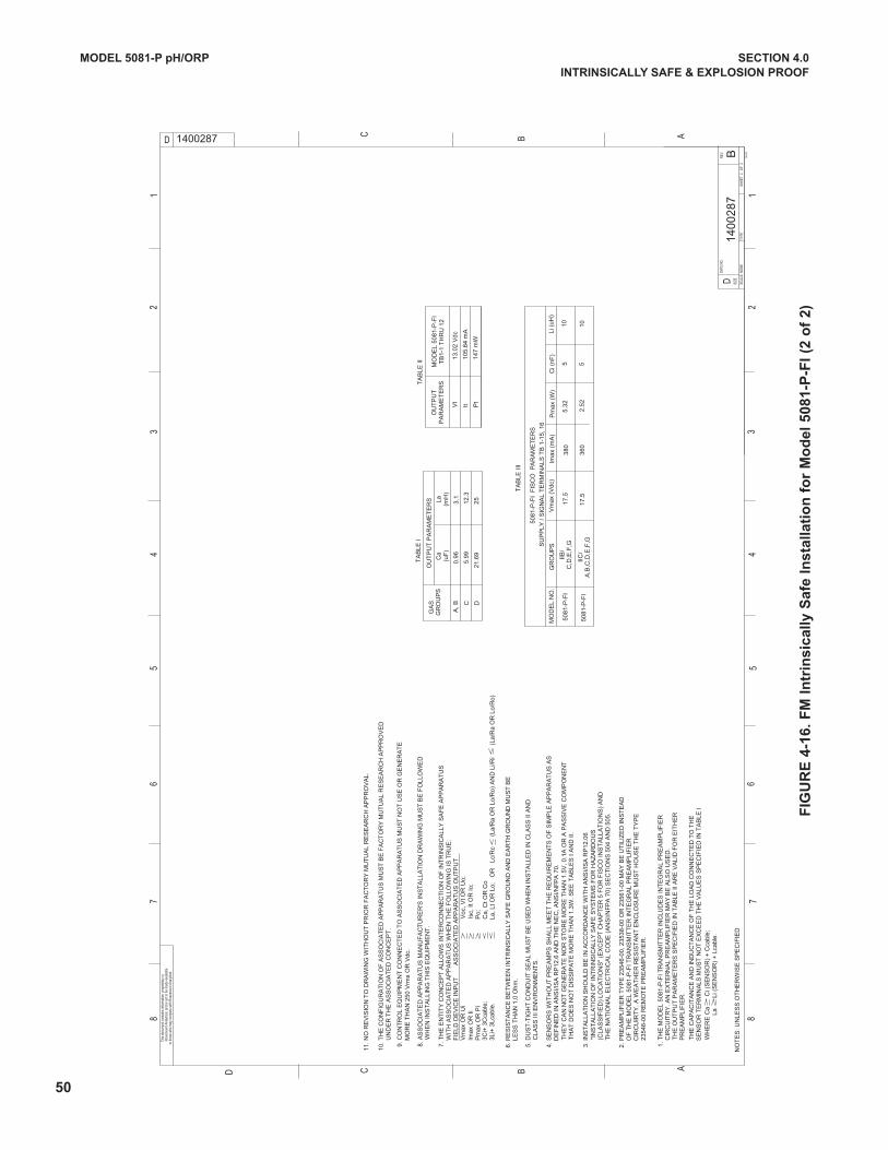
IIC/
A,B
,C,D
,E,F
,G
IIB/
C,D
,E,F
,G
GR
OU
PS
360
17.5
550
81-P
-FI
102.
52
380
17.5
5
5081
-P-F
I F
ISC
O P
AR
AM
ET
ER
S
5081
-P-F
I
TA
BLE
III
MO
DE
L N
O.
105.
32
Vm
ax (
Vdc
)Li
(uH
)C
i (nF
)P
max
(W
)Im
ax (
mA
)
SU
PP
LY /
SIG
NA
L T
ER
MIN
ALS
TB
1-1
5, 1
6
La, L
t OR
Lo;
O
R
Lc/R
c
(La
/Ra
OR
Lo/
Ro)
AN
D L
i/Ri
(
La/R
a O
R L
o/R
o)
GR
OU
PS
GA
SO
UT
PU
T P
AR
AM
ET
ER
S 2521
.69
(mH
)La
(uF
)C
a
C D
TA
BLE
I
12.3
3.1
5.99
0.96
A, B
147
mW
105.
64 m
A
13.0
2 V
dc
Pt
TB
1-1
TH
RU
12
MO
DE
L 50
81-P
-FI
TA
BLE
II
Vt
It
PA
RA
ME
TE
RS
OU
TP
UT
3
Li+
3Lc
able
.
3C
i+ 3
Cca
ble;
P
max
OR
Pi
Po;
Im
ax O
R Ii
Isc,
It O
R Io
;
Vm
ax O
R U
i
V
oc, V
t OR
Uo;
F
IELD
DE
VIC
E IN
PU
T
A
SS
OC
IAT
ED
AP
PA
RA
TU
S O
UT
PU
T
WIT
H A
SS
OC
IAT
ED
AP
PA
RA
TU
S W
HE
N T
HE
FO
LLO
WIN
G IS
TR
UE
: 7
. T
HE
EN
TIT
Y C
ON
CE
PT
ALL
OW
S I
NT
ER
CO
NN
EC
TIO
N O
F IN
TR
INS
ICA
LLY
SA
FE
AP
PA
RA
TU
S
Ca,
Ct O
R C
o
23
546-
00 R
EM
OT
E P
RE
AM
PLI
FIE
R.
C
IRC
UIR
TY
. A W
EA
TH
ER
RE
SIS
TA
NT
EN
CLO
SU
RE
MU
ST
HO
US
E T
HE
TY
PE
O
F T
HE
MO
DE
L 50
81-P
-FI T
RA
NS
MIT
TE
R IN
TE
GR
AL
PR
EA
MP
LIF
IER
2. P
RE
AM
PLI
FIE
R T
YP
E 2
3546
-00,
235
38-0
0 O
R 2
3561
-00
MA
Y B
E U
TIL
IZE
D IN
ST
EA
D
T
HA
T D
OE
S N
OT
DIS
SIP
AT
E M
OR
E T
HA
N 1
.3W
. SE
E T
AB
LES
I A
ND
II.
T
HE
Y C
AN
NO
T G
EN
ER
AT
E N
OR
ST
OR
E M
OR
E T
HA
N 1
.5V
, 0.1
A O
R A
PA
SS
IVE
CO
MP
ON
EN
T
DE
FIN
ED
IN A
NS
I/IS
A R
P12
.6 A
ND
TH
E N
EC
, AN
SI/N
FP
A 7
0.4.
SE
NS
OR
S W
ITH
OU
T P
RE
AM
PS
SH
ALL
ME
ET
TH
E R
EQ
UIR
EM
EN
TS
OF
SIM
PLE
AP
PA
RA
TU
S A
S
S
EN
SO
R T
ER
MIN
ALS
MU
ST
NO
T E
XC
EE
D T
HE
VA
LUE
S S
PE
CIF
IED
IN T
AB
LE I
T
HE
CA
PA
CIT
AN
CE
AN
D IN
DU
CT
AN
CE
OF
TH
E L
OA
D C
ON
NE
CT
ED
TO
TH
E
P
RE
AM
PLI
FIE
R.
T
HE
OU
TP
UT
PA
RA
ME
TE
RS
SP
EC
IFIE
D IN
TA
BLE
II A
RE
VA
LID
FO
R E
ITH
ER
C
IRC
UIT
RY
. AN
EX
TE
RN
AL
PR
EA
MP
LIF
IER
MA
Y B
E A
LSO
US
ED
.1.
TH
E M
OD
EL
5081
-P-F
I TR
AN
SM
ITT
ER
IN
CLU
DE
S IN
TE
GR
AL
PR
EA
MP
LIF
IER
La
Li
(S
EN
SO
R)
+ L
cabl
e.W
HE
RE
Ca
C
i (S
EN
SO
R)
+ C
cabl
e;
W
HE
N IN
ST
ALL
ING
TH
IS E
QU
IPM
EN
T.
8. A
SS
OC
IAT
ED
AP
PA
RA
TU
S M
AN
UF
AC
TU
RE
R'S
INS
TA
LLA
TIO
N D
RA
WIN
G M
US
T B
E F
OLL
OW
ED
11. N
O R
EV
ISIO
N T
O D
RA
WIN
G W
ITH
OU
T P
RIO
R F
AC
TO
RY
MU
TU
AL
RE
SE
AR
CH
AP
PR
OV
AL.
10. T
HE
CO
NF
IGU
RA
TIO
N O
F A
SS
OC
IAT
ED
AP
PA
RA
TU
S M
US
T B
E F
AC
TO
RY
MU
TU
AL
RE
SE
AR
CH
AP
PR
OV
ED
UN
DE
R T
HE
AS
SO
CIA
TE
D C
ON
CE
PT
.
M
OR
E T
HA
N 2
50 V
rms
OR
Vdc
. 9
. CO
NT
RO
L E
QU
IPM
EN
T C
ON
NE
CT
ED
TO
AS
SO
CIA
TE
D A
PP
AR
AT
US
MU
ST
NO
T U
SE
OR
GE
NE
RA
TE
LE
SS
TH
AN
1.0
Ohm
.6.
RE
SIS
TA
NC
E B
ET
WE
EN
INT
RIN
SIC
ALL
Y S
AF
E G
RO
UN
D A
ND
EA
RT
H G
RO
UN
D M
US
T B
E
C
LAS
S II
I EN
VIR
ON
ME
NT
S.
5. D
US
T-T
IGH
T C
ON
DU
IT S
EA
L M
US
T B
E U
SE
D W
HE
N IN
ST
ALL
ED
IN C
LAS
S II
AN
D
(C
LAS
SIF
IED
) LO
CA
TIO
NS
" (E
XC
EP
T C
HA
PT
ER
5 F
OR
FIS
CO
INS
TA
LLA
TIO
NS
) A
ND
T
HE
NA
TIO
NA
L E
LEC
TR
ICA
L C
OD
E (
AN
SI/N
FP
A 7
0) S
EC
TIO
NS
504
AN
D 5
05.
"I
NS
TA
LLA
TIO
N O
F IN
TR
INS
ICA
LLY
SA
FE
SY
ST
EM
S F
OR
HA
ZA
RD
OU
S3.
INS
TA
LLA
TIO
N S
HO
ULD
BE
IN A
CC
OR
DA
NC
E W
ITH
AN
SI/I
SA
RP
12.0
6
NO
TE
S: U
NLE
SS
OT
HE
RW
ISE
SP
EC
IFIE
DSC
ALE:
NO
NESH
EET
2
OF
2
1400287
B14
002
87
87
65
43
21
87
65
43
21
D B AC
D ABC
08-9
4
D
to th
ose
who
may
com
pete
with
Ros
emou
nt A
nalyt
ical
.Ro
sem
ount
Ana
lytic
al, a
nd is
not
to b
e m
ade
avai
labl
eTh
is do
cum
ent c
onta
ins
info
rmat
ion
pro
prie
tary
to
TYPE
REV
DWG
NO
.
SIZE
50
FIG
UR
E 4
-16
. F
M I
ntr
ins
ica
lly
Sa
fe I
ns
talla
tio
n f
or
Mo
de
l 5
08
1-P
-FI
(2 o
f 2
)
MODEL 5081-P pH/ORP SECTION 4.0
INTRINSICALLy SAFE & ExPLOSION PROOF
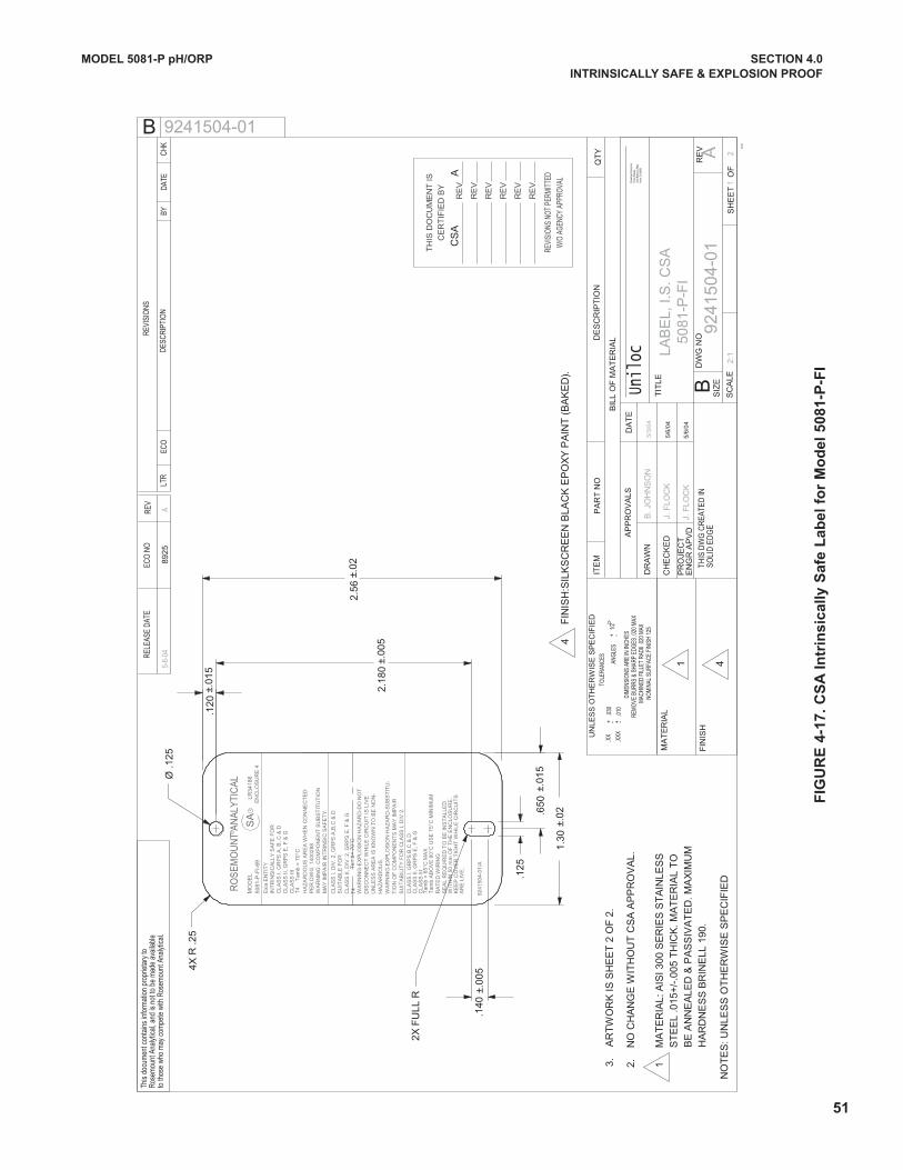
51
MODEL 5081-P pH/ORP SECTION 4.0
INTRINSICALLy SAFE & ExPLOSION PROOF
FIG
UR
E 4
-17
. C
SA
In
trin
sic
ally
Sa
fe L
ab
el
for
Mo
de
l 5
08
1-P
-FI
CLA
SS
I, D
IV. 2
, GR
PS
A,B
,C &
D
MO
DE
LS
AR
LR34
186
RO
SE
MO
UN
T A
NA
LYTI
CA
LR
WA
RN
ING
-EX
PL
OS
ION
HA
ZA
RD
-DO
NO
TD
ISC
ON
NE
CT
WH
ILE
CIR
CU
IT I
S L
IVE
UN
LES
S A
RE
A I
S K
NO
WN
TO
BE
NO
N-
HA
ZA
RD
OU
S.
WA
RN
ING
-EX
PL
OS
ION
HA
ZA
RD
-SU
BS
TIT
U-
TIO
N O
F C
OM
PO
NE
NT
S M
AY
IMP
AIR
SU
ITA
BIL
ITY
FO
R C
LAS
S I,
DIV
2.
CLA
SS
I, G
RP
S B
,C &
DC
LAS
S II
, GR
PS
E, F
& G
CLA
SS
III
Tam
b =
65°
C M
AX
Tam
b A
BO
VE
60°
C U
SE
75°
C M
INIM
UM
RA
TE
D W
IRIN
G
EN
CL
OS
UR
E 4
SU
ITA
BLE
FO
RC
LAS
S II
, DIV
. 2, G
RP
S E
, F
& G
Exi
a E
NT
ITY
INT
RIN
SIC
ALL
Y S
AF
E F
OR
CLA
SS
I, G
RP
S A
, B
, C &
DC
LAS
S II
, GR
PS
E,
F &
GC
LAS
S I
IIT
4
Tam
b =
70°
CH
AZ
AR
DO
US
AR
EA
WH
EN
CO
NN
EC
TE
DP
ER
DW
G.
1400
288
WA
RN
ING
: CO
MP
ON
EN
T S
UB
ST
ITU
TIO
NM
AY
IMP
AIR
INT
RIN
SIC
SA
FE
TY
.
Tam
b= 7
0°C
SE
AL
RE
QU
IRE
D T
O B
E IN
ST
ALL
ED
WIT
HIN
50
mm
OF
TH
E E
NC
LO
SU
RE
.K
EE
P C
OV
ER
TIG
HT
WH
ILE
CIR
CU
ITS
AR
E L
IVE
.
9241
504-
01/A
TH
IS D
OC
UM
EN
T IS
CE
RT
IFIE
D B
Y
RE
V
RE
V
RE
V
RE
V
RE
V
RE
V
REVI
SION
S NO
T PE
RMIT
TED
W/O
AGE
NCY
APPR
OVAL
DIM
ENSI
ONS
ARE
IN IN
CHES
REM
OVE
BUR
RS &
SHA
RP E
DGES
.020
MAX
MAC
HINE
D FI
LLET
RAD
II .0
20 M
AX
-
ITE
MP
AR
T N
OD
ES
CR
IPT
ION
QT
Y
SC
ALE
SIZ
E
RE
VD
WG
NO
BIL
L O
F M
AT
ER
IAL
MA
TE
RIA
L
FIN
ISH
DR
AW
N
CH
EC
KE
D
PR
OJE
CT
EN
GR
AP
VD
NO
TE
S: U
NLE
SS
OT
HE
RW
ISE
SP
EC
IFIE
D
REV
ECO
NO
RELE
ASE
DATE
LTR
ECO
REVI
SIO
NS
DESC
RIPT
ION
BYDA
TECH
K
This
docu
men
t con
tain
s in
form
atio
n pr
oprie
tary
toRo
sem
ount
Ana
lytic
al, a
nd is
not
to b
e m
ade
avai
labl
eto
thos
e wh
o m
ay c
ompe
te w
ith R
osem
ount
Ana
lytic
al.
BTH
IS D
WG
CR
EATE
D IN
SOLI
D E
DG
E
DA
TE
B
TIT
LE
AP
PR
OV
ALS
+ - +.0
10.X
XX
.XX
.030
- 1
/2+
ANG
LES
UN
LES
S O
TH
ER
WIS
E S
PE
CIF
IED
TOLE
RANC
ES
10-9
6
SH
EE
T
OF
21
9241
504
-01
A
L
AB
EL,
I.S
. C
SA
2:1
J. F
LOC
K
B. J
OH
NS
ON
9241504-01
A89
255-
6-04
NOM
INAL
SUR
FACE
FIN
ISH
125
5/3/
04
5/6/
04
Rose
mou
nt A
nalyt
ical,
Unilo
c Di
vision
2400
Bar
ranc
a Pk
wyIrv
ine,
CA
9260
6Un
iloc
1
3.
AR
TW
OR
K IS
SH
EE
T 2
OF
2.
2.
NO
CH
AN
GE
WIT
HO
UT
CS
A A
PP
RO
VA
L.
4X
2X F
ULL
R
1
MA
TE
RIA
L: A
ISI 3
00 S
ER
IES
ST
AIN
LES
SS
TE
EL
.015
+/-
.005
TH
ICK
. MA
TE
RIA
L T
O
BE
AN
NE
ALE
D &
PA
SS
IVA
TE
D. M
AX
IMU
MH
AR
DN
ES
S B
RIN
ELL
190
.
508
1-P
-FI
508
1-P
-FI-
69
4
FIN
ISH
:SIL
KS
CR
EE
N B
LAC
K E
PO
XY
PA
INT
(B
AK
ED
).
4
T4
R .2
5
Ø .1
25
±.01
5.1
20
±.00
52.
180
±.02
2.56
.125
±.01
5.6
50
±.02
1.30
±.00
5.1
40
J. F
LOC
K5/
6/04
CS
AA
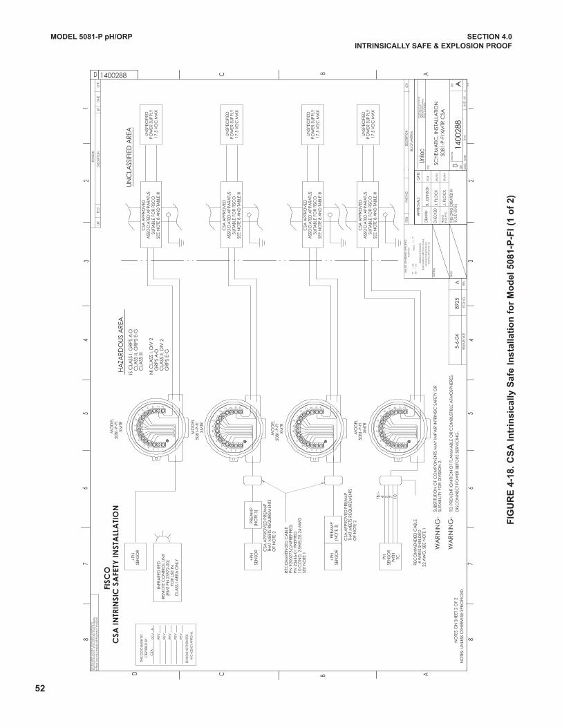
Ro
sem
ou
nt A
na
lytic
al,
Uni
loc
Div
isio
n24
00 B
arr
an
ca
Pkw
yIrv
ine
, CA
926
06
UN
LESS
OTH
ERW
ISE
SPEC
IFIE
D
DIM
ENSIO
NS A
RE IN
INC
HES
REM
OVE
BURR
S & SH
ARP
EDG
ES .0
20 M
AXM
ACHI
NED
FILLE
T RAD
II .02
0 M
AX
FINISH
MAT
ERIA
L
PRO
JEC
TEN
GR
APVD
SIZE
DWG
NO
.RE
V
TITLE
E PYTELA
CS
This
docu
men
t con
tain
s inf
orm
atio
n p
ropr
ieta
ry to
Rose
mou
nt A
nalyt
ical
, and
is n
ot to
be
mad
e av
aila
ble
to th
ose
who
may
com
pete
with
Ros
emou
nt A
nalyt
ical
.
CHE
CKE
D
DRA
WN
THIS
DW
G C
REA
TED
IN
DA
TE
DESC
RIPT
ION
BILL
OF M
ATER
IAL
QTY
ITEM
PART
NO
.
RELE
ASE
DATE
ECO
NO
.RE
V
LTR
ECO
YBN
O ITPIRCSE D
DATE
REVI
SION
CHK
SOLID
ED
GE
TOLE
RANC
ES
-+ -
+AN
GLE
S-+
.010
.XXX
.XX
.030
APP
ROVA
LS
D
110
-96
AB
23
45
87
6
87
65
43
21
AB
C
D C
D
1400
288
ANO
NESH
EET
OF
12
1400288
8925
A
NOM
INAL
SURF
ACE
FINISH
125
5-3-
04
5/6/
04
Unilo
c
SCH
EMA
TIC
, IN
STA
LLA
TIO
N
THIS
DO
CUM
ENT
ISC
ERTI
FIED
BY R
EV
REV
REV
REV
REV
REV
REVI
SIONS
NO
T PER
MITT
EDW
/O A
GEN
CY A
PPRO
VAL
B. J
OHN
SON
J. F
LOC
K
5-6-
04
5081
-P-F
I XM
TR C
SA
PHSE
NSO
RW
ITH
TC
UN
SPEC
IFIE
DPO
WER
SU
PPLY
17.5
VD
C M
AX
MO
DEL
5081
-P-F
IX
MTR
MO
DEL
5081
-P-F
IX
MTR
MO
DEL
5081
-P-F
IXM
TR
MO
DEL
5081
-P-F
IXM
TR
INFR
AR
ED R
EDR
EMO
TE C
ON
TRO
L U
NIT
(RM
T PN
235
72-0
0)FO
R U
SE IN
CLA
SS I
AR
EA O
NLY
+PH
SEN
SOR
PREA
MP
(NO
TE 3
)+
PHSE
NSO
R
TB1-
4 5 7 10
PREA
MP
(NO
TE 3
)+
PHSE
NSO
R
WA
RN
ING
-
WA
RN
ING
-
1234
5
6
7
8
9
10
11
1213 14 15 16
1234
5
6
7
8
9
10
11
1213 14 15 16
1234
5
6
7
8
9
10
11
1213 14 15 16
1234
5
6
7
8
9
10
11
1213 14 15 16
TO P
REV
ENT
IGN
ITIO
N O
F FL
AM
MA
BLE
OR
CO
MBU
STIB
LE A
TMO
SPH
ERES
,D
ISC
ON
NEC
T PO
WER
BEF
OR
E SE
RVI
CIN
G.
UN
CLA
SSIF
IED
AR
EA
SUBS
TITU
TIO
N O
F C
OM
PON
ENTS
MA
Y IM
PA
IR IN
TRIN
SIC
SA
FETY
OR
SUIT
ABI
LITY
FO
R D
IVIS
ION
2.
R
ECO
MM
END
ED C
ABL
E
4 W
IRES
SH
IELD
ED
22
AW
G. S
EE N
OTE
1
REC
OM
MEN
DED
CA
BLE
PN 9
2002
73 (U
NPR
EPPE
D)
PN 2
3646
-01
PREP
PED
10 C
ON
D, 2
SH
IELD
S 24
AW
GSE
E N
OTE
1
CSA
APP
RO
VED
PR
EAM
PTH
AT
MEE
TS R
EQU
IREM
ENTS
OF
NO
TE 2
CSA
APP
RO
VED
PR
EAM
PTH
AT
MEE
TS R
EQU
IREM
ENTS
OF
NO
TE 2
IS C
LASS
I, G
RPS
A-D
C
LASS
II, G
RPS
E-G
C
LASS
III
NI C
LASS
I, D
IV 2
G
RPS
A-D
C
LASS
II, D
IV 2
G
RPS
E-G
HA
ZAR
DO
US
AR
EAC
SA IN
TRIN
SIC
SA
FETY
INST
ALL
ATI
ON
CSA
APP
RO
VED
ASS
OC
IATE
D A
PPA
RATU
SSU
ITA
BLE
FOR
FIS
CO
SEE
NO
TE 8
AN
D T
ABL
E III
UN
SPEC
IFIE
DPO
WER
SU
PPLY
17.5
VD
C M
AX
CSA
APP
RO
VED
ASS
OC
IATE
D A
PPA
RATU
SSU
ITA
BLE
FOR
FIS
CO
SEE
NO
TE 8
AN
D T
ABL
E III
UN
SPEC
IFIE
DPO
WER
SU
PPLY
17.5
VD
C M
AX
CSA
APP
RO
VED
ASS
OC
IATE
D A
PPA
RATU
SSU
ITA
BLE
FOR
FIS
CO
SEE
NO
TE 8
AN
D T
ABL
E III
UN
SPEC
IFIE
DPO
WER
SU
PPLY
17.5
VD
C M
AX
CSA
APP
RO
VED
ASS
OC
IATE
D A
PPA
RATU
SSU
ITA
BLE
FOR
FIS
CO
SEE
NO
TE 8
AN
D T
ABL
E III
NO
TES:
UN
LESS
OTH
ERW
ISE
SPEC
IFIC
EDN
OTE
S O
N S
HEE
T 2
OF
2
FISC
O
J. F
LOC
K5/
6/04
CSA
A
52
MODEL 5081-P pH/ORP SECTION 4.0
INTRINSICALLy SAFE & ExPLOSION PROOF
FIG
UR
E 4
-18
. C
SA
In
trin
sic
ally
Sa
fe I
ns
talla
tio
n f
or
Mo
de
l 5
08
1-P
-FI
(1 o
f 2
)
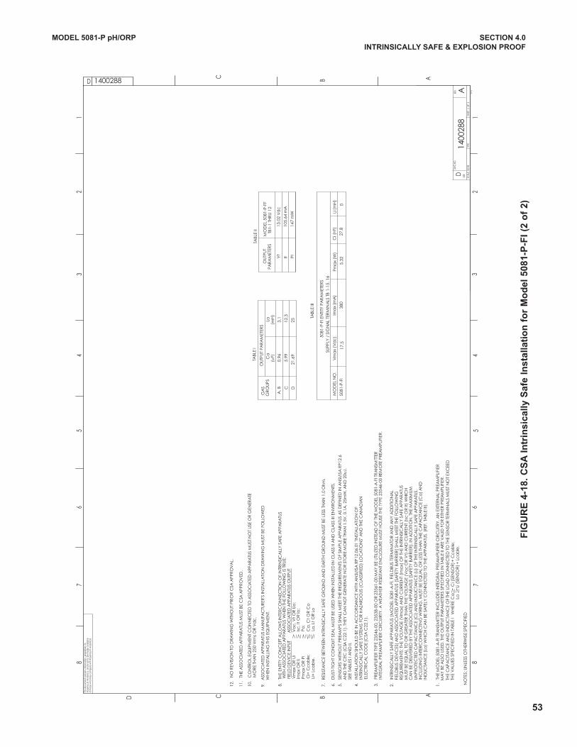
53
MODEL 5081-P pH/ORP SECTION 4.0
INTRINSICALLy SAFE & ExPLOSION PROOF
FIG
UR
E 4
-18
. C
SA
In
trin
sic
ally
Sa
fe I
ns
talla
tio
n f
or
Mo
de
l 5
08
1-P
-FI
(2 o
f 2
)
SIZE
DWG
NO
.RE
V
TYPE
This
docu
men
t con
tain
s inf
orm
atio
n p
ropr
ieta
ry to
Rose
mou
nt A
nalyt
ical
, and
is n
ot to
be
mad
e av
aila
ble
to th
ose
who
may
com
pete
with
Ros
emou
nt A
nalyt
ical
.
D
08-9
4
C B AD
C ABD1
23
45
67
8
12
34
56
78
1400
288
A
1400288
SHEE
T 2
OF
2SC
ALE:
NO
NEN
OTE
S: U
NLE
SS O
THER
WIS
E SP
ECIF
IED
SUPP
LY /
SIG
NA
L TE
RMIN
ALS
TB
1-15
, 16
Ima
x (m
A)
Pma
x (W
)C
i (n
F)Li
(m
H)
5.32
TABL
E III
5081
-P-F
I EN
TITY
PA
RA
MET
ERS
Vm
ax
(Vd
c)
MO
DEL
NO
.
5081
-P-F
I27
.80
17.5
380
10.
CO
NTR
OL
EQU
IPM
ENT
CO
NN
ECTE
D T
O A
SSO
CIA
TED
APP
ARA
TUS
MU
ST N
OT
USE
OR
GEN
ERA
TE
MO
RE
THA
N 2
50 V
rms
OR
Vd
c.
6.
DU
ST-T
IGH
T C
ON
DU
IT S
EAL
MU
ST B
E U
SED
WH
EN IN
STA
LLED
IN C
LASS
II A
ND
CLA
SS II
I EN
VIR
ON
MEN
TS.
11.
TH
E A
SSO
CIA
TED
APP
AR
ATU
S M
UST
BE
CSA
APP
RO
VED
.
12.
NO
REV
ISIO
N T
O D
RAW
ING
WITH
OU
T PR
IOR
CSA
APP
RO
VA
L.
7.
RES
ISTA
NC
E BE
TWEE
N IN
TRIN
SIC
ALL
Y SA
FE G
RO
UN
D A
ND
EA
RTH
GR
OU
ND
MU
ST B
E LE
SS T
HA
N 1
.0 O
hm.
2.
INTR
INSI
CA
LLY
SAFE
APP
ARA
TUS
(MO
DEL
508
1-A
-FI,
FIEL
DBU
S TE
RM
INA
TOR
AN
D A
NY
AD
DIT
ION
AL
FI
ELD
BUS
DEV
ICES
) AN
D A
SSO
CIA
TED
APP
AR
ATU
S (S
AFE
TY B
AR
RIE
R) S
HA
LL M
EET
THE
FOLL
OW
ING
R
EQU
IREM
ENTS
: TH
E V
OLT
AG
E (V
ma
x) A
ND
CU
RRE
NT
(Ima
x) O
F TH
E IN
TRIN
SIC
ALL
Y SA
FE A
PPA
RA
TUS
M
UST
BE
EQU
AL
TO O
R G
REA
TER
TH
AN
TH
E V
OLT
AG
E (V
oc
OR
Vt)
AN
D C
UR
REN
T (Is
c O
R It
) W
HIC
H
CA
N B
E D
ELIV
ERED
BY
THE
ASS
OC
IATE
D A
PPA
RATU
S (S
AFE
TY B
AR
RIE
R).
IN A
DD
ITIO
N, T
HE
MA
XIM
UM
U
NPR
OTE
CTE
D C
APA
CIT
AN
CE
(Ci)
AN
D IN
DU
CTA
NC
E (L
i) O
F TH
E IN
TRIN
SIC
ALL
Y SA
FE A
PPA
RA
TUS,
IN
CLU
DIN
G IN
TER
CO
NN
ECTI
NG
WIR
ING
, MU
ST B
E EQ
UA
L O
R L
ESS
THA
N T
HE
CA
PAC
ITA
NC
E (C
a)
AN
D
IND
UC
TAN
CE
(La
) W
HIC
H C
AN
BE
SAFE
LY C
ON
NEC
TED
TO
TH
E A
PPA
RATU
S. (
REF.
TA
BLE
III).
WH
ERE
Ca
Ci (
SEN
SOR
) + C
ca
ble
;
La
Li (
SEN
SOR
) + L
ca
ble
.
1.
THE
MO
DEL
508
1-A
-FI T
RA
NSM
ITTE
R IN
CLU
DES
INTE
GRA
L PR
EAM
PLIF
IER
CIR
CU
ITR
Y. A
N E
XTER
NA
L PR
EAM
PLIF
IER
M
AY
BE A
LSO
USE
D. T
HE
OU
TPU
T PA
RAM
ETER
S SP
ECIF
IED
IN T
ABL
E II
ARE
VA
LID
FO
R EI
THER
PR
EAM
PLIF
IER
.
9.
ASS
OC
IATE
D A
PPA
RATU
S M
AN
UFA
CTU
RER
'S IN
STA
LLA
TIO
N D
RAW
ING
MU
ST B
E FO
LLO
WED
W
HEN
INST
ALL
ING
TH
IS E
QU
IPM
ENT.
TH
E C
APA
CIT
AN
CE
AN
D IN
DU
CTA
NC
E O
F TH
E LO
AD
CO
NN
ECTE
D T
O T
HE
SEN
SOR
TER
MIN
ALS
MU
ST N
OT
EXC
EED
TH
E V
ALU
ES S
PEC
IFIE
D IN
TA
BLE
I
3.
PREA
MPL
IFIE
R T
YPE
2354
6-00
, 235
38-0
0 O
R 23
561-
00 M
AY
BE U
TILI
ZED
INST
EAD
OF
THE
MO
DEL
508
1-A
-FI T
RA
NSM
ITTE
R
INTE
GRA
L PR
EAM
PLIF
IER
CIR
CU
IRTY
. A W
EATH
ER R
ESIS
TAN
T EN
CLO
SURE
MU
ST H
OU
SE T
HE
TYPE
235
46-0
0 RE
MO
TE P
REA
MPL
IFIE
R.
5.
SEN
SOR
S W
ITHO
UT
PREA
MPS
SH
ALL
MEE
T TH
E R
EQU
IREM
ENTS
OF
SIM
PLE
APP
AR
ATU
S A
S D
EFIN
ED IN
AN
SI/I
SA R
P12.
6
AN
D T
HE
CEC
(C
SA C
22.1
). TH
EY C
AN
NO
T G
ENER
ATE
NO
R S
TOR
E M
OR
E TH
AN
1.5
V, 0
.1A
, 25m
W, A
ND
20u
J.
SEE
TABL
ES I
AN
D II
.
4.
INST
ALL
ATI
ON
SH
OU
LD B
E IN
AC
CO
RD
AN
CE
WIT
H A
NSI
/ISA
RP1
2.06
.01
"INST
ALL
ATI
ON
OF
IN
TRIN
SIC
ALL
Y SA
FE S
YSTE
MS
FOR
HA
ZAR
DO
US
(CLA
SSIF
IED
) LO
CA
TIO
NS"
AN
D T
HE
CA
NA
DIA
N
ELE
CTR
ICA
L C
OD
E (C
SA C
22.1
).
Ca
, Ct
OR
Co
La, L
t O
R L
o
W
ITH A
SSO
CIA
TED
APP
ARA
TUS
WH
EN T
HE
FOLL
OW
ING
IS T
RUE:
F
IELD
DEV
ICE
INPU
T
A
SSO
CIA
TED
APP
AR
ATU
S O
UTP
UT
V
ma
x O
R U
i
Ima
x O
R Ii
P
ma
x O
R P
i
Ci+
Cc
ab
le;
L
i+ L
ca
ble
.
8.
THE
ENTI
TY C
ON
CEP
T A
LLO
WS
INTE
RC
ON
NEC
TIO
N O
F IN
TRIN
SIC
ALL
Y SA
FE A
PPA
RA
TUS
Po;
Isc
, It
OR
Io;
Vo
c, V
t O
R U
o;
OU
TPU
TPA
RAM
ETER
S
ItVt
TABL
E II
MO
DEL
508
1-P-
FFTB
1-1
THRU
12
Pt
13.0
2 V
dc
105.
64 m
A
147
mW
A, B
0.96
5.99
3.1
12.3
TABL
E I
DC
Ca
(uF)
La(m
H)
21.6
925
OU
TPU
T PA
RA
MET
ERS
GA
SG
RO
UPS
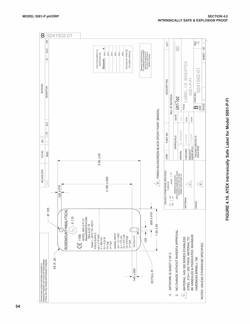
924
150
2-01
/A
DIM
ENSI
ONS
ARE
IN IN
CHES
REM
OVE
BUR
RS &
SHA
RP E
DGES
.020
MAX
MAC
HINE
D FI
LLET
RAD
II .0
20 M
AX
-
ITE
MP
AR
T N
OD
ES
CR
IPT
ION
QT
Y
SC
ALE
SIZ
E
RE
VD
WG
NO
BIL
L O
F M
AT
ER
IAL
MA
TE
RIA
L
FIN
ISH
DR
AW
N
CH
EC
KE
D
PR
OJE
CT
EN
GR
AP
VD
NO
TE
S: U
NLE
SS
OT
HE
RW
ISE
SP
EC
IFIE
D
REV
ECO
NO
RELE
ASE
DATE
LTR
ECO
REVI
SIO
NS
DESC
RIPT
ION
BYDA
TECH
K
This
docu
men
t con
tain
s in
form
atio
n pr
oprie
tary
toRo
sem
ount
Ana
lytic
al, a
nd is
not
to b
e m
ade
avai
labl
eto
thos
e wh
o m
ay c
ompe
te w
ith R
osem
ount
Ana
lytic
al.
BTH
IS D
WG
CR
EATE
D IN
SOLI
D E
DG
E
DA
TE
B
TIT
LE
AP
PR
OV
ALS
+ - +.0
10.X
XX
.XX
.030
- 1
/2+
ANG
LES
UN
LES
S O
TH
ER
WIS
E S
PE
CIF
IED
TOLE
RANC
ES
10-9
6
SH
EE
T
OF
21
9241
502
-01
A
LA
BE
L, I.
S. B
AS
/AT
EX
2:1
J. F
LOC
K
J. F
LOC
K
B. J
OH
NS
ON
9241502-01
A89
255-
6-04
NOM
INAL
SUR
FACE
FIN
ISH
125
5/3
/04
5/6/
04
5/6/
04
Rose
mou
nt A
nalyt
ical,
Unilo
c Di
vision
2400
Bar
ranc
a Pk
wyIrv
ine,
CA
9260
6Un
iloc
1
3.
AR
TW
OR
K IS
SH
EE
T 2
OF
2.
2.
NO
CH
AN
GE
WIT
HO
UT
BA
SE
EF
A A
PP
RO
VA
L.
4X
2X F
ULL
R
508
1-P
-FI
1
MA
TE
RIA
L: A
ISI 3
00 S
ER
IES
ST
AIN
LES
S
S
TE
EL
.01
5+/-
.005
TH
ICK
. MA
TE
RIA
L T
O
BE
AN
NE
ALE
D &
PA
SS
IVA
TE
D. M
AX
IMU
M
H
AR
DN
ES
S B
RIN
ELL
190
.
RO
SEM
OU
NT
AN
ALYT
ICAL
SIG
NA
L IN
PU
T
RR
II 1
G
1180 EE
x ia
IIC
T4
Tam
b =
-20
°C T
O +
65°C
Bas
eefa
02A
TE
X12
84
Li=
0 H
MO
DE
L 50
81-P
-FI-
73
4
FIN
ISH
:SIL
KS
CR
EE
N B
LAC
K E
PO
XY
PA
INT
(B
AK
ED
).
4
Uo
= 1
3.1
VD
CIo
= 1
73 m
AP
o =
231
mW
Ci=
0.0
10
F
TH
IS D
OC
UM
EN
T I
S
CE
RT
IFIE
D B
Y
RE
V
RE
V
RE
V
RE
V
RE
V
RE
V
REVI
SION
S NO
T PE
RMIT
TED
W/O
AGE
NCY
APPR
OVAL
FIS
CO
SU
PP
LYU
i = 1
7.5
VD
CIi
= 3
80 m
AP
i = 5
.32
WC
i= 0
F μμ
No
mod
ifica
tions
per
mitt
edw
ithou
t the
app
rova
l of
the
Au
thor
ized
Per
son
Rel
ated
Dra
win
g
Bas
eefa
Cer
tifie
d P
rodu
ct
R .2
5
±.01
5.1
20
Ø .1
25
±.00
52.
180
±.02
2.56
.125
±.01
5.6
50
±.02
1.30
±.00
5.1
40
Li=
0
H μμ
Bas
eefa
A
54
FIG
UR
E 4
.19
. A
TE
x I
ntr
ins
ica
lly
Sa
fe L
ab
el
for
Mo
de
l 5
08
1-P
-FI
MODEL 5081-P pH/ORP SECTION 4.0
INTRINSICALLy SAFE & ExPLOSION PROOF
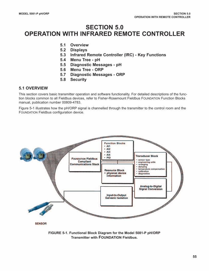
55
MODEL 5081-P pH/ORP SECTION 5.0
OPERATION wITH REMOTE CONTROLLER
SECTION 5.0OPERATION wITH INFRARED REMOTE CONTROLLER
5.1 Overview
5.2 Displays
5.3 Infrared Remote Controller (IRC) - Key Functions
5.4 Menu Tree - pH
5.5 Diagnostic Messages - pH
5.6 Menu Tree - ORP
5.7 Diagnostic Messages - ORP
5.8 Security
5.1 OvERvIEw
This section covers basic transmitter operation and software functionality. For detailed descriptions of the func-tion blocks common to all Fieldbus devices, refer to Fisher-Rosemount Fieldbus FOuNdATION Function Blocksmanual, publication number 00809-4783.
Figure 5-1 illustrates how the pH/ORP signal is channelled through the transmitter to the control room and theFOuNdATION Fieldbus configuration device.
FIGURE 5-1. Functional Block Diagram for the Model 5081-P pH/ORP
Transmitter with FOUNDATION Fieldbus.
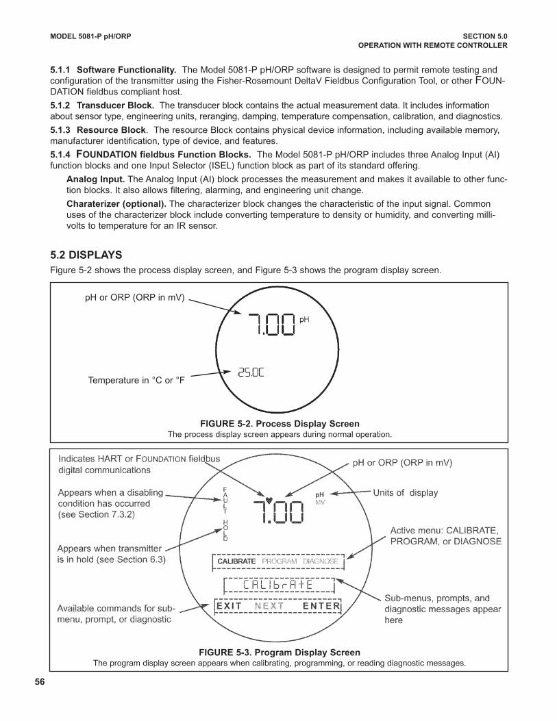
56
MODEL 5081-P pH/ORP SECTION 5.0
OPERATION wITH REMOTE CONTROLLER
FIGURE 5-3. Program Display ScreenThe program display screen appears when calibrating, programming, or reading diagnostic messages.
FIGURE 5-2. Process Display ScreenThe process display screen appears during normal operation.
pH or ORP (ORP in mV)
Temperature in °C or °F
5.2 DISPLAyS
Figure 5-2 shows the process display screen, and Figure 5-3 shows the program display screen.
5.1.1 Software Functionality. The Model 5081-P pH/ORP software is designed to permit remote testing andconfiguration of the transmitter using the Fisher-Rosemount deltaV Fieldbus Configuration Tool, or other FOuN-dATION fieldbus compliant host.
5.1.2 Transducer Block. The transducer block contains the actual measurement data. It includes informationabout sensor type, engineering units, reranging, damping, temperature compensation, calibration, and diagnostics.
5.1.3 Resource Block. The resource Block contains physical device information, including available memory,manufacturer identification, type of device, and features.
5.1.4 FOUNDATION fieldbus Function Blocks. The Model 5081-P pH/ORP includes three Analog Input (AI)function blocks and one Input Selector (ISEL) function block as part of its standard offering.
Analog Input. The Analog Input (AI) block processes the measurement and makes it available to other func-tion blocks. It also allows filtering, alarming, and engineering unit change.
Charaterizer (optional). The characterizer block changes the characteristic of the input signal. Commonuses of the characterizer block include converting temperature to density or humidity, and converting milli-volts to temperature for an IR sensor.
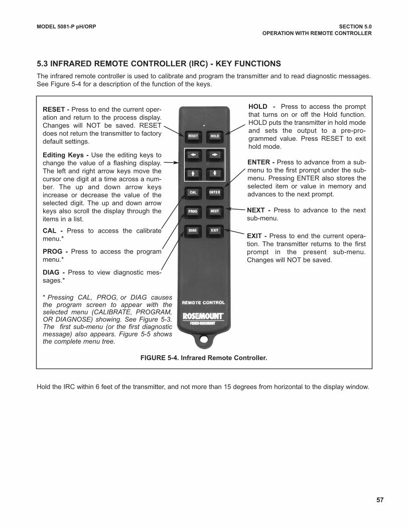
57
MODEL 5081-P pH/ORP SECTION 5.0
OPERATION wITH REMOTE CONTROLLER
5.3 INFRARED REMOTE CONTROLLER (IRC) - KEy FUNCTIONS
The infrared remote controller is used to calibrate and program the transmitter and to read diagnostic messages.See Figure 5-4 for a description of the function of the keys.
Hold the IRC within 6 feet of the transmitter, and not more than 15 degrees from horizontal to the display window.
FIGURE 5-4. Infrared Remote Controller.
RESET - Press to end the current oper-ation and return to the process display.Changes will NOT be saved. RESETdoes not return the transmitter to factorydefault settings.
CAL - Press to access the calibratemenu.*
PROG - Press to access the programmenu.*
DIAG - Press to view diagnostic mes-sages.*
HOLD - Press to access the promptthat turns on or off the Hold function.HOLd puts the transmitter in hold modeand sets the output to a pre-pro-grammed value. Press RESET to exithold mode.
Editing Keys - use the editing keys tochange the value of a flashing display.The left and right arrow keys move thecursor one digit at a time across a num-ber. The up and down arrow keysincrease or decrease the value of theselected digit. The up and down arrowkeys also scroll the display through theitems in a list.
* Pressing CAL, PROG, or DIAG causesthe program screen to appear with theselected menu (CALIBRATE, PROGRAM,OR DIAGNOSE) showing. See Figure 5-3.The first sub-menu (or the first diagnosticmessage) also appears. Figure 5-5 showsthe complete menu tree.
ENTER - Press to advance from a sub-menu to the first prompt under the sub-menu. Pressing ENTER also stores theselected item or value in memory andadvances to the next prompt.
NExT - Press to advance to the nextsub-menu.
ExIT - Press to end the current opera-tion. The transmitter returns to the firstprompt in the present sub-menu.Changes will NOT be saved.
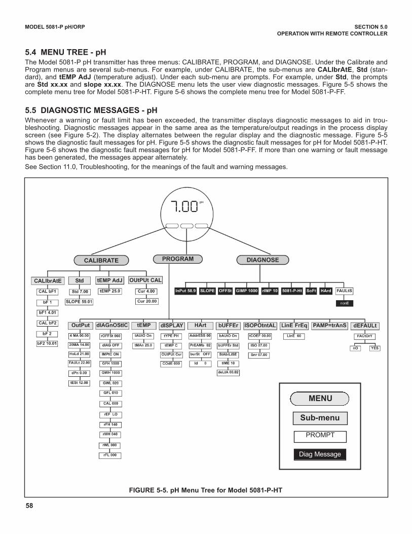
58
MODEL 5081-P pH/ORP SECTION 5.0
OPERATION wITH REMOTE CONTROLLER
FIGURE 5-5. pH Menu Tree for Model 5081-P-HT
5.4 MENU TREE - pHThe Model 5081-P pH transmitter has three menus: CALIBRATE, PROGRAM, and dIAGNOSE. under the Calibrate andProgram menus are several sub-menus. For example, under CALIBRATE, the sub-menus are CALIbrAtE, Std (stan-dard), and tEMP AdJ (temperature adjust). under each sub-menu are prompts. For example, under Std, the promptsare Std xx.xx and slope xx.xx. The dIAGNOSE menu lets the user view diagnostic messages. Figure 5-5 shows thecomplete menu tree for Model 5081-P-HT. Figure 5-6 shows the complete menu tree for Model 5081-P-FF.
5.5 DIAGNOSTIC MESSAGES - pHWhenever a warning or fault limit has been exceeded, the transmitter displays diagnostic messages to aid in trou-bleshooting. diagnostic messages appear in the same area as the temperature/output readings in the process displayscreen (see Figure 5-2). The display alternates between the regular display and the diagnostic message. Figure 5-5shows the diagnostic fault messages for pH. Figure 5-5 shows the diagnostic fault messages for pH for Model 5081-P-HT.Figure 5-6 shows the diagnostic fault messages for pH for Model 5081-P-FF. If more than one warning or fault messagehas been generated, the messages appear alternately.
See Section 11.0, Troubleshooting, for the meanings of the fault and warning messages.
MENU
Sub-menu
PROMPT
diag Message
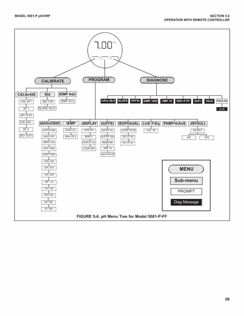
MODEL 5081-P pH/ORP SECTION 5.0
OPERATION wITH REMOTE CONTROLLER
FIGURE 5-6. pH Menu Tree for Model 5081-P-FF
MENU
Sub-menu
PROMPT
diag Message
PROGRAMCALIBRATE
GIMP 1000 5081-P-FF SoFtInPut 58.9 FAULtS
nonE
rIMP 10
dIAGnOStIC tEMP bUFFErdISPLAy ISOPOtntAL LinE FrEq PAMP=trAnS
CALIbrAtE Std tEMP AdJ
tEMP 25.0
tAutO On
tMAn 25.0
tYPE PH
tEMP C
OutPut Cur
COdE 000
bAutO On
buFFEr Std
StAbiLiSE
tIME 10
deLtA 00.02
tCOEF 00.00
ISO 07.00
Snr 07.00
LinE 60
dEFAULt
FActOrY
YESNO
rOFFSt 060
dIAG OFF
IMPtC ON
GWH 1000
GFH 1500
GWL 020
GFL 010
CAL 000
rEF LO
rFH 140
rWH 040
rWL 000
rFL 000
CAL bF1
bF 1
bF1 4.01
CAL bF2
bF 2
bF2 10.01
DIAGNOSE
Std 7.00
SLOPE 59.01
SLOPE OFFSt HArd
59
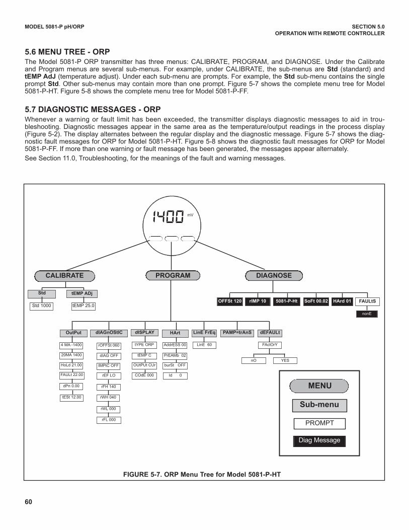
60
MODEL 5081-P pH/ORP SECTION 5.0
OPERATION wITH REMOTE CONTROLLER
5.6 MENU TREE - ORPThe Model 5081-P ORP transmitter has three menus: CALIBRATE, PROGRAM, and dIAGNOSE. under the Calibrateand Program menus are several sub-menus. For example, under CALIBRATE, the sub-menus are Std (standard) andtEMP AdJ (temperature adjust). under each sub-menu are prompts. For example, the Std sub-menu contains the singleprompt Std. Other sub-menus may contain more than one prompt. Figure 5-7 shows the complete menu tree for Model5081-P-HT. Figure 5-8 shows the complete menu tree for Model 5081-P-FF.
5.7 DIAGNOSTIC MESSAGES - ORPWhenever a warning or fault limit has been exceeded, the transmitter displays diagnostic messages to aid in trou-bleshooting. diagnostic messages appear in the same area as the temperature/output readings in the process display(Figure 5-2). The display alternates between the regular display and the diagnostic message. Figure 5-7 shows the diag-nostic fault messages for ORP for Model 5081-P-HT. Figure 5-8 shows the diagnostic fault messages for ORP for Model5081-P-FF. If more than one warning or fault message has been generated, the messages appear alternately.
See Section 11.0, Troubleshooting, for the meanings of the fault and warning messages.
FIGURE 5-7. ORP Menu Tree for Model 5081-P-HT
MENU
Sub-menu
PROMPT
diag Message
PROGRAMCALIBRATE
OutPut
OFFSt 120 5081-P-Ht FAULtS
nO YES
nonE
dIAGnOStIC dISPLAy LinE FrEq
Std tEMP ADj
tEMP 25.0
4 MA -1400
20MA 1400
HoLd 21.00
FAuLt 22.00
dPn 0.00
tYPE ORP
tEMP C
OutPut Cur
COdE 000
LinE 60
dEFAULt
FActOrYrOFFSt 060
dIAG OFF
IMPtC OFF
rEF LO
rFH 140
rWH 040
rWL 000
rFL 000
Std 1000
DIAGNOSE
tESt 12.00
rIMP 10 SoFt 00.02 HArd 01
PAMP=trAnSHArt
AddrESS 00
PrEAMb 02
burSt OFF
Id 0
1400 mV
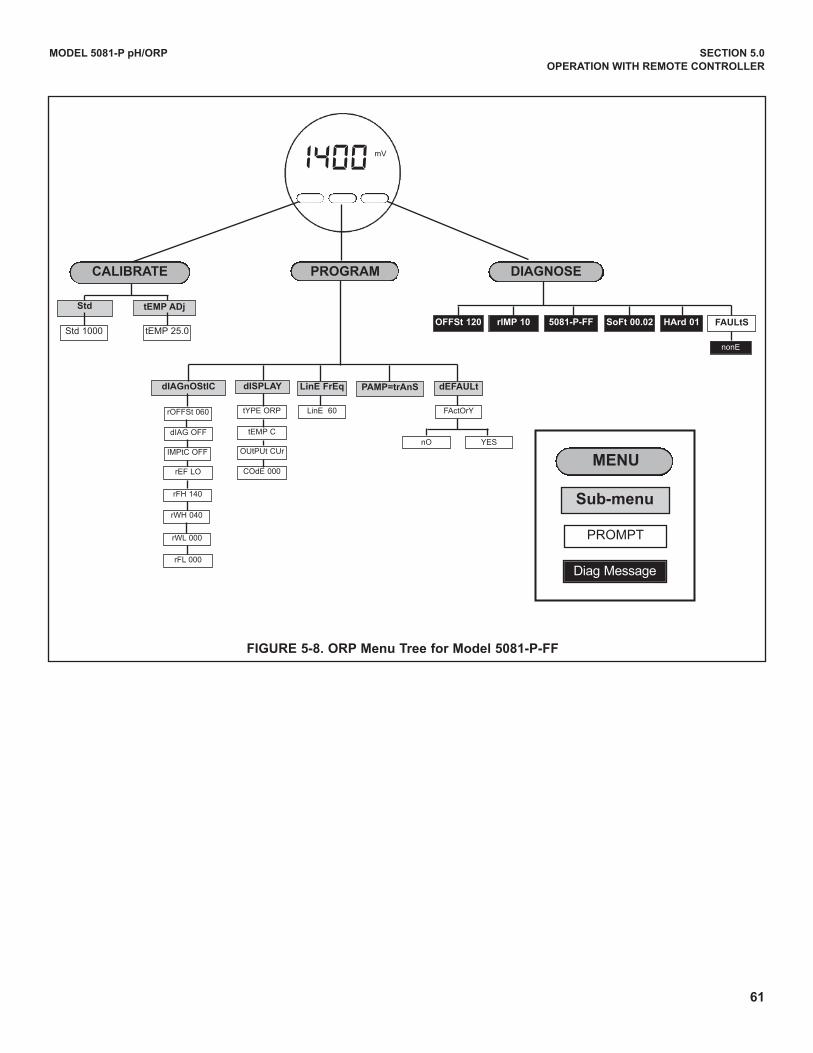
61
MODEL 5081-P pH/ORP SECTION 5.0
OPERATION wITH REMOTE CONTROLLER
FIGURE 5-8. ORP Menu Tree for Model 5081-P-FF
MENU
Sub-menu
PROMPT
diag Message
PROGRAMCALIBRATE
OFFSt 120 5081-P-FF FAULtS
nonE
dIAGnOStIC dISPLAy LinE FrEq
Std tEMP ADj
tEMP 25.0
tYPE ORP
tEMP C
OutPut Cur
COdE 000
LinE 60rOFFSt 060
dIAG OFF
IMPtC OFF
rEF LO
rFH 140
rWH 040
rWL 000
rFL 000
Std 1000
DIAGNOSE
rIMP 10 SoFt 00.02 HArd 01
PAMP=trAnS
nO YES
dEFAULt
FActOrY
1400 mV
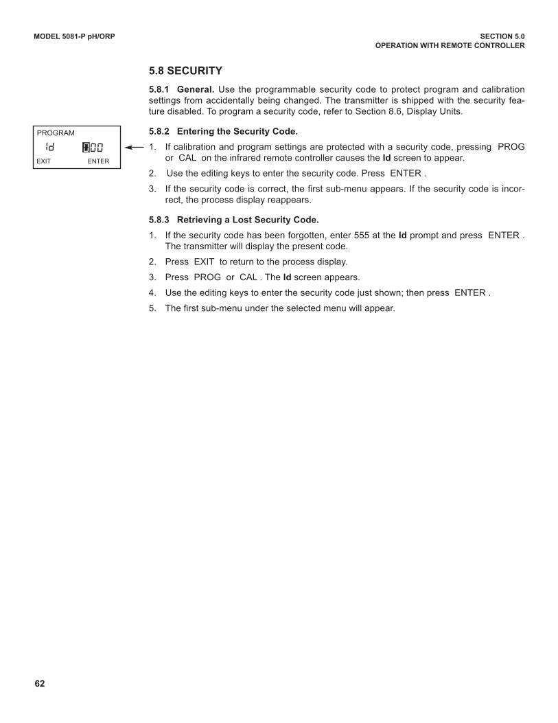
62
5.8 SECURITy
5.8.1 General. use the programmable security code to protect program and calibrationsettings from accidentally being changed. The transmitter is shipped with the security fea-ture disabled. To program a security code, refer to Section 8.6, display units.
5.8.2 Entering the Security Code.
1. If calibration and program settings are protected with a security code, pressing PROGor CAL on the infrared remote controller causes the Id screen to appear.
2. use the editing keys to enter the security code. Press ENTER .
3. If the security code is correct, the first sub-menu appears. If the security code is incor-rect, the process display reappears.
5.8.3 Retrieving a Lost Security Code.
1. If the security code has been forgotten, enter 555 at the Id prompt and press ENTER .The transmitter will display the present code.
2. Press EXIT to return to the process display.
3. Press PROG or CAL . The Id screen appears.
4. use the editing keys to enter the security code just shown; then press ENTER .
5. The first sub-menu under the selected menu will appear.
MODEL 5081-P pH/ORP SECTION 5.0
OPERATION wITH REMOTE CONTROLLER
PROGRAM
IdEXIT ENTER
000
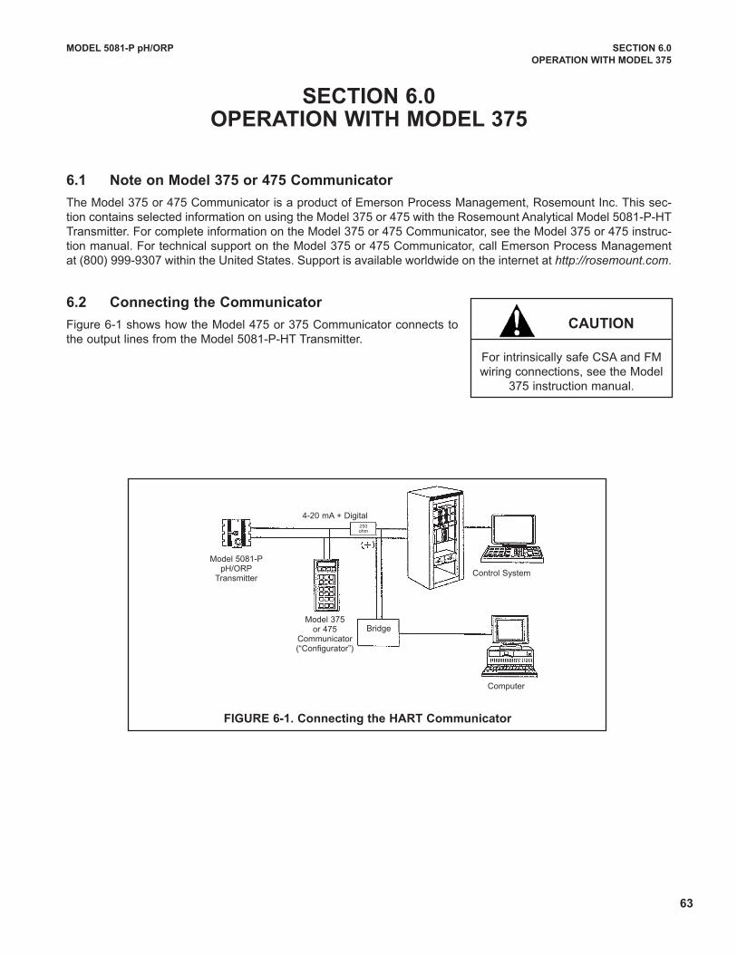
MODEL 5081-P pH/ORP SECTION 6.0
OPERATION wITH MODEL 375
SECTION 6.0OPERATION wITH MODEL 375
6.1 Note on Model 375 or 475 Communicator
The Model 375 or 475 Communicator is a product of Emerson Process Management, Rosemount Inc. This sec-tion contains selected information on using the Model 375 or 475 with the Rosemount Analytical Model 5081-P-HTTransmitter. For complete information on the Model 375 or 475 Communicator, see the Model 375 or 475 instruc-tion manual. For technical support on the Model 375 or 475 Communicator, call Emerson Process Managementat (800) 999-9307 within the united States. Support is available worldwide on the internet at http://rosemount.com.
6.2 Connecting the Communicator
Figure 6-1 shows how the Model 475 or 375 Communicator connects tothe output lines from the Model 5081-P-HT Transmitter.
CAUTION
For intrinsically safe CSA and FMwiring connections, see the Model
375 instruction manual.
FIGURE 6-1. Connecting the HART Communicator
4-20 mA + digital250 ohm
Control System
Computer
Model 5081-P pH/ORP
Transmitter
BridgeModel 375
or 475Communicator(“Configurator”)
63
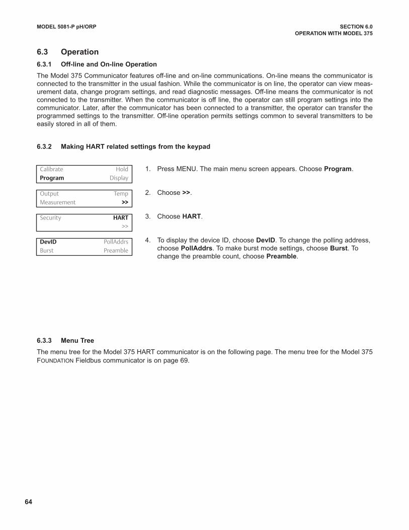
64
6.3 Operation
6.3.1 Off-line and On-line Operation
The Model 375 Communicator features off-line and on-line communications. On-line means the communicator isconnected to the transmitter in the usual fashion. While the communicator is on line, the operator can view meas-urement data, change program settings, and read diagnostic messages. Off-line means the communicator is notconnected to the transmitter. When the communicator is off line, the operator can still program settings into thecommunicator. Later, after the communicator has been connected to a transmitter, the operator can transfer theprogrammed settings to the transmitter. Off-line operation permits settings common to several transmitters to beeasily stored in all of them.
6.3.2 Making HART related settings from the keypad
6.3.3 Menu Tree
The menu tree for the Model 375 HART communicator is on the following page. The menu tree for the Model 375FOuNdATION Fieldbus communicator is on page 69.
1. Press MENu. The main menu screen appears. Choose Program.
2. Choose >>.
3. Choose HART.
4. To display the device Id, choose DevID. To change the polling address,choose PollAddrs. To make burst mode settings, choose Burst. Tochange the preamble count, choose Preamble.
MODEL 5081-P pH/ORP SECTION 6.0
OPERATION wITH MODEL 375
Calibrate Hold
Program Display
Output Temp
Measurement >>
Security HART
>>
DevID PollAddrs
Burst Preamble
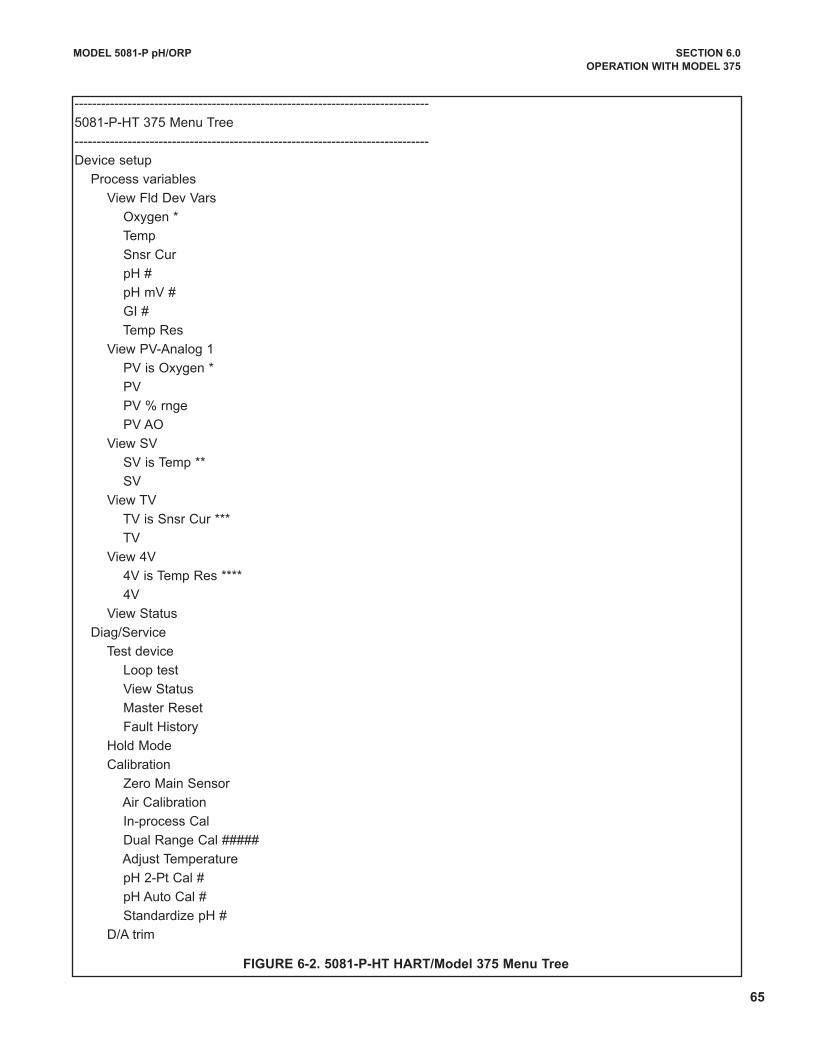
MODEL 5081-P pH/ORP SECTION 6.0
OPERATION wITH MODEL 375
--------------------------------------------------------------------------------
5081-P-HT 375 Menu Tree
--------------------------------------------------------------------------------
device setup
Process variables
View Fld dev Vars
Oxygen *
Temp
Snsr Cur
pH #
pH mV #
GI #
Temp Res
View PV-Analog 1
PV is Oxygen *
PV
PV % rnge
PV AO
View SV
SV is Temp **
SV
View TV
TV is Snsr Cur ***
TV
View 4V
4V is Temp Res ****
4V
View Status
diag/Service
Test device
Loop test
View Status
Master Reset
Fault History
Hold Mode
Calibration
Zero Main Sensor
Air Calibration
In-process Cal
dual Range Cal #####
Adjust Temperature
pH 2-Pt Cal #
pH Auto Cal #
Standardize pH #
d/A trim
FIGURE 6-2. 5081-P-HT HART/Model 375 Menu Tree
65
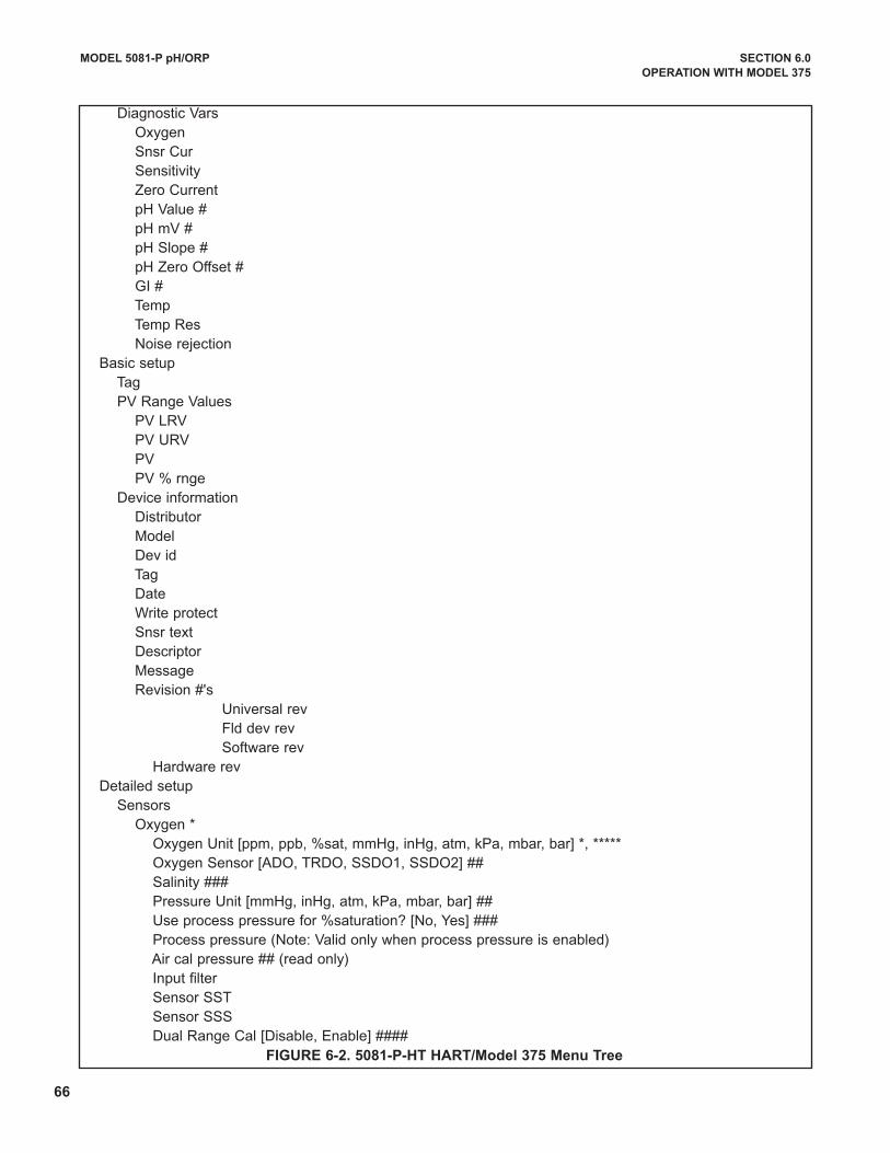
66
MODEL 5081-P pH/ORP SECTION 6.0
OPERATION wITH MODEL 375
diagnostic VarsOxygenSnsr CurSensitivityZero CurrentpH Value #pH mV #pH Slope #pH Zero Offset #GI #TempTemp ResNoise rejection
Basic setupTagPV Range Values
PV LRVPV uRVPVPV % rnge
device informationdistributorModeldev idTagdateWrite protectSnsr textdescriptorMessageRevision #'s
universal revFld dev revSoftware rev
Hardware revdetailed setup
SensorsOxygen *
Oxygen unit [ppm, ppb, %sat, mmHg, inHg, atm, kPa, mbar, bar] *, *****Oxygen Sensor [AdO, TRdO, SSdO1, SSdO2] ##Salinity ###Pressure unit [mmHg, inHg, atm, kPa, mbar, bar] ##use process pressure for %saturation? [No, Yes] ###Process pressure (Note: Valid only when process pressure is enabled)Air cal pressure ## (read only)Input filterSensor SSTSensor SSSdual Range Cal [disable, Enable] ####
FIGURE 6-2. 5081-P-HT HART/Model 375 Menu Tree
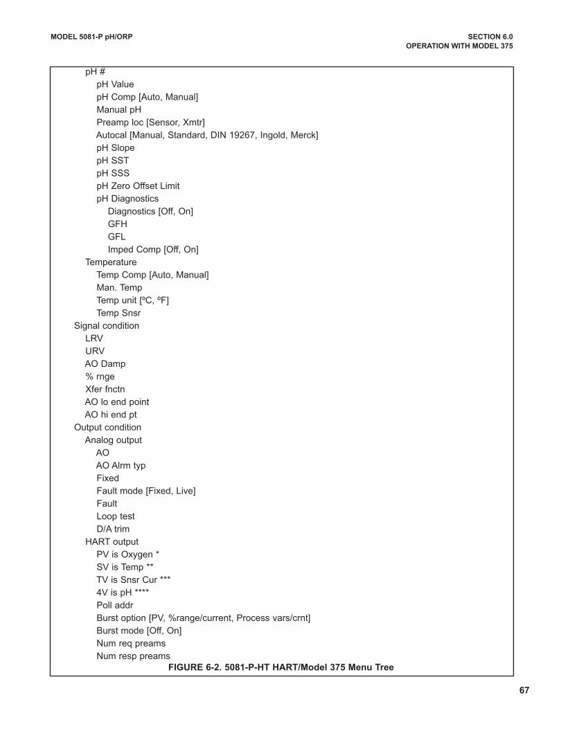
MODEL 5081-P pH/ORP SECTION 6.0
OPERATION wITH MODEL 375
pH #
pH Value
pH Comp [Auto, Manual]
Manual pH
Preamp loc [Sensor, Xmtr]
Autocal [Manual, Standard, dIN 19267, Ingold, Merck]
pH Slope
pH SST
pH SSS
pH Zero Offset Limit
pH diagnostics
diagnostics [Off, On]
GFH
GFL
Imped Comp [Off, On]
Temperature
Temp Comp [Auto, Manual]
Man. Temp
Temp unit [ºC, ºF]
Temp Snsr
Signal condition
LRV
uRV
AO damp
% rnge
Xfer fnctn
AO lo end point
AO hi end pt
Output condition
Analog output
AO
AO Alrm typ
Fixed
Fault mode [Fixed, Live]
Fault
Loop test
d/A trim
HART output
PV is Oxygen *
SV is Temp **
TV is Snsr Cur ***
4V is pH ****
Poll addr
Burst option [PV, %range/current, Process vars/crnt]
Burst mode [Off, On]
Num req preams
Num resp preamsFIGURE 6-2. 5081-P-HT HART/Model 375 Menu Tree
67
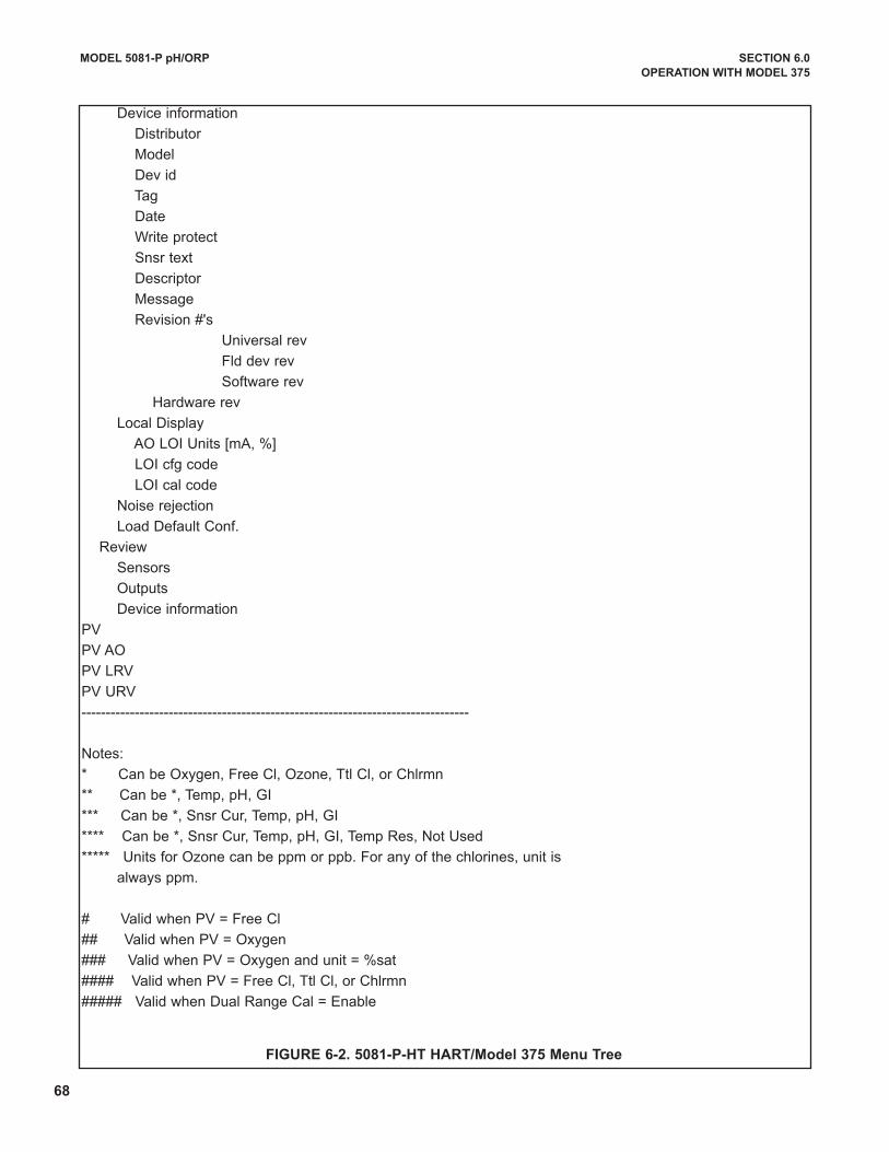
68
MODEL 5081-P pH/ORP SECTION 6.0
OPERATION wITH MODEL 375
device information
distributor
Model
dev id
Tag
date
Write protect
Snsr text
descriptor
Message
Revision #'s
universal rev
Fld dev rev
Software rev
Hardware rev
Local display
AO LOI units [mA, %]
LOI cfg code
LOI cal code
Noise rejection
Load default Conf.
Review
Sensors
Outputs
device information
PV
PV AO
PV LRV
PV uRV
--------------------------------------------------------------------------------
Notes:
* Can be Oxygen, Free Cl, Ozone, Ttl Cl, or Chlrmn
** Can be *, Temp, pH, GI
*** Can be *, Snsr Cur, Temp, pH, GI
**** Can be *, Snsr Cur, Temp, pH, GI, Temp Res, Not used
***** units for Ozone can be ppm or ppb. For any of the chlorines, unit is
always ppm.
# Valid when PV = Free Cl
## Valid when PV = Oxygen
### Valid when PV = Oxygen and unit = %sat
#### Valid when PV = Free Cl, Ttl Cl, or Chlrmn
##### Valid when dual Range Cal = Enable
FIGURE 6-2. 5081-P-HT HART/Model 375 Menu Tree
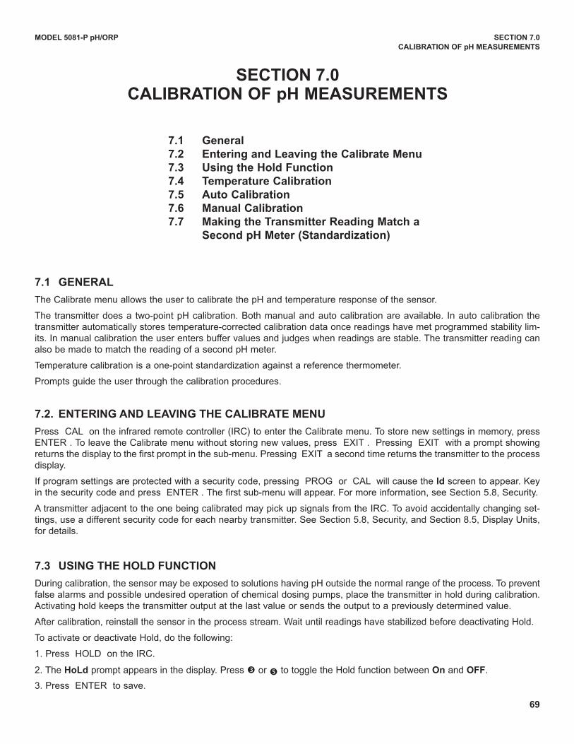
69
MODEL 5081-P pH/ORP SECTION 7.0
CALIBRATION OF pH MEASUREMENTS
SECTION 7.0CALIBRATION OF pH MEASUREMENTS
7.1 General
7.2 Entering and Leaving the Calibrate Menu
7.3 Using the Hold Function
7.4 Temperature Calibration
7.5 Auto Calibration
7.6 Manual Calibration
7.7 Making the Transmitter Reading Match a
Second pH Meter (Standardization)
7.1 GENERAL
The Calibrate menu allows the user to calibrate the pH and temperature response of the sensor.
The transmitter does a two-point pH calibration. Both manual and auto calibration are available. In auto calibration thetransmitter automatically stores temperature-corrected calibration data once readings have met programmed stability lim-its. In manual calibration the user enters buffer values and judges when readings are stable. The transmitter reading canalso be made to match the reading of a second pH meter.
Temperature calibration is a one-point standardization against a reference thermometer.
Prompts guide the user through the calibration procedures.
7.2. ENTERING AND LEAvING THE CALIBRATE MENU
Press CAL on the infrared remote controller (IRC) to enter the Calibrate menu. To store new settings in memory, pressENTER . To leave the Calibrate menu without storing new values, press EXIT . Pressing EXIT with a prompt showingreturns the display to the first prompt in the sub-menu. Pressing EXIT a second time returns the transmitter to the processdisplay.
If program settings are protected with a security code, pressing PROG or CAL will cause the Id screen to appear. Keyin the security code and press ENTER . The first sub-menu will appear. For more information, see Section 5.8, Security.
A transmitter adjacent to the one being calibrated may pick up signals from the IRC. To avoid accidentally changing set-tings, use a different security code for each nearby transmitter. See Section 5.8, Security, and Section 8.5, display units,for details.
7.3 USING THE HOLD FUNCTION
during calibration, the sensor may be exposed to solutions having pH outside the normal range of the process. To preventfalse alarms and possible undesired operation of chemical dosing pumps, place the transmitter in hold during calibration.Activating hold keeps the transmitter output at the last value or sends the output to a previously determined value.
After calibration, reinstall the sensor in the process stream. Wait until readings have stabilized before deactivating Hold.
To activate or deactivate Hold, do the following:
1. Press HOLd on the IRC.
2. The HoLd prompt appears in the display. Press é or ê to toggle the Hold function between On and OFF.
3. Press ENTER to save.
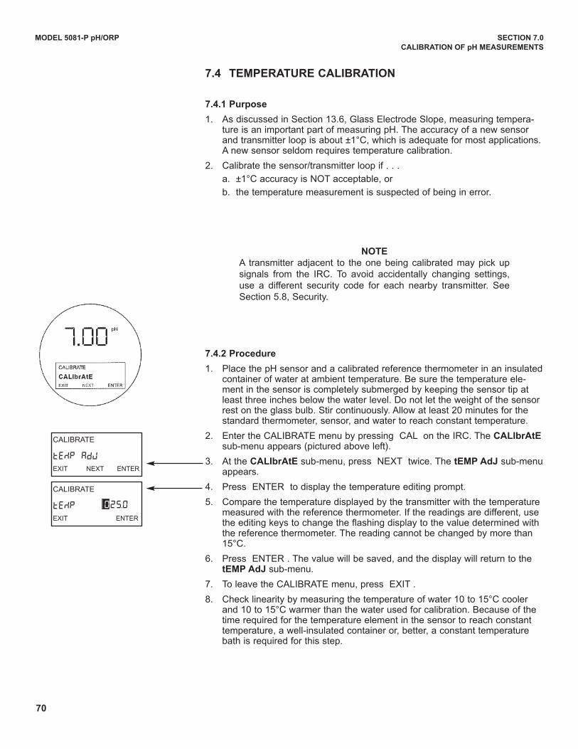
70
CALIBRATE
tEMP AdJEXIT NEXT ENTER
CALIBRATE
tEMP EXIT ENTER
025.0
MODEL 5081-P pH/ORP SECTION 7.0
CALIBRATION OF pH MEASUREMENTS
7.4 TEMPERATURE CALIBRATION
7.4.1 Purpose
1. As discussed in Section 13.6, Glass Electrode Slope, measuring tempera-ture is an important part of measuring pH. The accuracy of a new sensorand transmitter loop is about ±1°C, which is adequate for most applications.A new sensor seldom requires temperature calibration.
2. Calibrate the sensor/transmitter loop if . . .
a. ±1°C accuracy is NOT acceptable, or
b. the temperature measurement is suspected of being in error.
NOTE
A transmitter adjacent to the one being calibrated may pick upsignals from the IRC. To avoid accidentally changing settings,use a different security code for each nearby transmitter. SeeSection 5.8, Security.
7.4.2 Procedure
1. Place the pH sensor and a calibrated reference thermometer in an insulatedcontainer of water at ambient temperature. Be sure the temperature ele-ment in the sensor is completely submerged by keeping the sensor tip atleast three inches below the water level. do not let the weight of the sensorrest on the glass bulb. Stir continuously. Allow at least 20 minutes for thestandard thermometer, sensor, and water to reach constant temperature.
2. Enter the CALIBRATE menu by pressing CAL on the IRC. The CALIbrAtEsub-menu appears (pictured above left).
3. At the CALIbrAtE sub-menu, press NEXT twice. The tEMP AdJ sub-menuappears.
4. Press ENTER to display the temperature editing prompt.
5. Compare the temperature displayed by the transmitter with the temperaturemeasured with the reference thermometer. If the readings are different, usethe editing keys to change the flashing display to the value determined withthe reference thermometer. The reading cannot be changed by more than15°C.
6. Press ENTER . The value will be saved, and the display will return to thetEMP AdJ sub-menu.
7. To leave the CALIBRATE menu, press EXIT .
8. Check linearity by measuring the temperature of water 10 to 15°C coolerand 10 to 15°C warmer than the water used for calibration. Because of thetime required for the temperature element in the sensor to reach constanttemperature, a well-insulated container or, better, a constant temperaturebath is required for this step.
71
7.5 AUTO CALIBRATION
7.5.1 Purpose
1. New sensors must be calibrated before use. Regular recalibration is also necessary.
2. The use of auto calibration instead of manual calibration is strongly recommended. Auto calibration avoids com-mon pitfalls and reduces errors.
3. For more information about calibration in pH measurements and the use of buffers, refer to Section 8.7, Buffers andCalibration.
7.5.2 what Happens During Auto Calibration?
1. The transmitter displays prompts that guide the user through a two-point buffer calibration.
2. The transmitter recognizes the buffers and uses the temperature-corrected pH value in the calibration. The trans-mitter also measures noise and drift and does not accept calibration data until readings are stable. Stability limitsare user-programmable. See Section 8.7, Buffer Calibration Parameters.
7.5.3 Use of Calibration Standards (buffers)
1. A pH measurement is only as good as the calibration, and the calibration is only as good as the buffers used. A care-ful buffer calibration is the first step in making an accurate pH measurement.
2. Calibrate with buffers having pH values that bracket the pH of the process. For example, if the pH is between 8 and9, calibrate with pH 7 and 10 buffers. Commercial buffers for intermediate range pH are readily available. Buffersoutside the range pH 3.0 to pH 10.0 may not be readily available and must be prepared by the user. Tables 7-2 and7-3 in Section 7.6, Buffer Calibration Parameters, list the buffers that the transmitter recognizes.
3. Allow time for the sensor and buffers to reach the same temperature. If the sensor was just removed from a processhaving a temperature more than 10°C different from the buffer, allow at least 20 minutes.
4. For best results, calibrate with buffers having the same temperature as the process. If the buffer and process tem-perature differ by more than about 15°C an error as great as 0.1pH may result.
5. Be careful using buffers at high temperatures. Protect the solution from evaporation. Evaporation changes the con-centration of the buffer and its pH. Be sure the pH of the buffer is defined at high temperatures. Finally, no matterwhat the temperature is, allow the entire measurement cell, sensor and solution, to reach constant temperaturebefore calibrating.
6. The pH of a buffer changes with temperature. Equations relating pH to temperature for common buffers have beenprogrammed into the Model 5081-P pH transmitter. during auto calibration, the transmitter calculates the correctbuffer value and uses it in the calibration.
7. Buffers have limited shelf lives. do not use a buffer if the expiration date has passed. Store buffers at controlled roomtemperature.
8. do not return used buffer to the stock bottle. discard it.
9. Protect buffers from excessive exposure to air. Atmospheric carbon dioxide lowers the pH of alkaline buffers. Othertrace gases commonly found in industrial environments, for example, ammonia and hydrogen chloride, also affectthe pH of buffers. Molds, from airborne spores, grow readily in neutral and slightly acidic buffers. Mold growth cansubstantially alter the pH of a buffer.
10. Rinse the sensor with deionized water before placing it in a buffer. Remove excess water from the sensor by gentlydaubing it with a clean tissue. do not wipe the sensor. Wiping may generate a static charge, leading to noisy read-ings. The static charge may take hours to dissipate. A few drops of deionized water carried with the sensor into thebuffer will not appreciably alter the pH.
MODEL 5081-P pH/ORP SECTION 7.0
CALIBRATION OF pH MEASUREMENTS
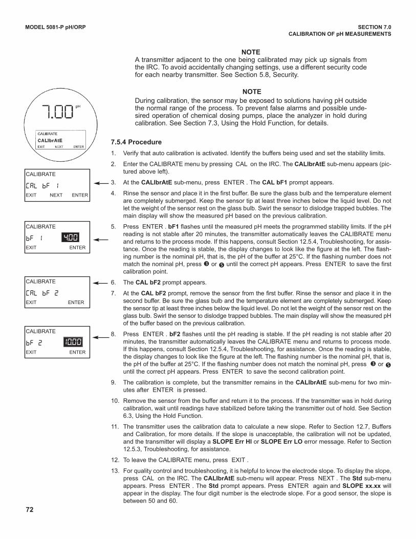
72
7.5.4 Procedure
1. Verify that auto calibration is activated. Identify the buffers being used and set the stability limits.
2. Enter the CALIBRATE menu by pressing CAL on the IRC. The CALIbrAtE sub-menu appears (pic-tured above left).
3. At the CALIbrAtE sub-menu, press ENTER . The CAL bF1 prompt appears.
4. Rinse the sensor and place it in the first buffer. Be sure the glass bulb and the temperature elementare completely submerged. Keep the sensor tip at least three inches below the liquid level. do notlet the weight of the sensor rest on the glass bulb. Swirl the sensor to dislodge trapped bubbles. Themain display will show the measured pH based on the previous calibration.
5. Press ENTER . bF1 flashes until the measured pH meets the programmed stability limits. If the pHreading is not stable after 20 minutes, the transmitter automatically leaves the CALIBRATE menuand returns to the process mode. If this happens, consult Section 12.5.4, Troubleshooting, for assis-tance. Once the reading is stable, the display changes to look like the figure at the left. The flash-ing number is the nominal pH, that is, the pH of the buffer at 25°C. If the flashing number does notmatch the nominal pH, press é or ê until the correct pH appears. Press ENTER to save the firstcalibration point.
6. The CAL bF2 prompt appears.
7. At the CAL bF2 prompt, remove the sensor from the first buffer. Rinse the sensor and place it in thesecond buffer. Be sure the glass bulb and the temperature element are completely submerged. Keepthe sensor tip at least three inches below the liquid level. do not let the weight of the sensor rest on theglass bulb. Swirl the sensor to dislodge trapped bubbles. The main display will show the measured pHof the buffer based on the previous calibration.
8. Press ENTER . bF2 flashes until the pH reading is stable. If the pH reading is not stable after 20minutes, the transmitter automatically leaves the CALIBRATE menu and returns to process mode.If this happens, consult Section 12.5.4, Troubleshooting, for assistance. Once the reading is stable,the display changes to look like the figure at the left. The flashing number is the nominal pH, that is,the pH of the buffer at 25°C. If the flashing number does not match the nominal pH, press é or êuntil the correct pH appears. Press ENTER to save the second calibration point.
9. The calibration is complete, but the transmitter remains in the CALIbrAtE sub-menu for two min-utes after ENTER is pressed.
10. Remove the sensor from the buffer and return it to the process. If the transmitter was in hold duringcalibration, wait until readings have stabilized before taking the transmitter out of hold. See Section6.3, using the Hold Function.
11. The transmitter uses the calibration data to calculate a new slope. Refer to Section 12.7, Buffersand Calibration, for more details. If the slope is unacceptable, the calibration will not be updated,and the transmitter will display a SLOPE Err HI or SLOPE Err LO error message. Refer to Section12.5.3, Troubleshooting, for assistance.
12. To leave the CALIBRATE menu, press EXIT .
13. For quality control and troubleshooting, it is helpful to know the electrode slope. To display the slope,press CAL on the IRC. The CALIbrAtE sub-menu will appear. Press NEXT . The Std sub-menuappears. Press ENTER . The Std prompt appears. Press ENTER again and SLOPE xx.xx willappear in the display. The four digit number is the electrode slope. For a good sensor, the slope isbetween 50 and 60.
CALIBRATE
bF 2EXIT ENTER
10.00
MODEL 5081-P pH/ORP SECTION 7.0
CALIBRATION OF pH MEASUREMENTS
NOTEA transmitter adjacent to the one being calibrated may pick up signals fromthe IRC. To avoid accidentally changing settings, use a different security codefor each nearby transmitter. See Section 5.8, Security.
NOTE
during calibration, the sensor may be exposed to solutions having pH outsidethe normal range of the process. To prevent false alarms and possible unde-sired operation of chemical dosing pumps, place the analyzer in hold duringcalibration. See Section 7.3, using the Hold Function, for details.
CALIBRATE
CAL bF 1EXIT NEXT ENTER
CALIBRATE
CAL bF 2EXIT ENTER
CALIBRATE
bF 1EXIT ENTER
4.00
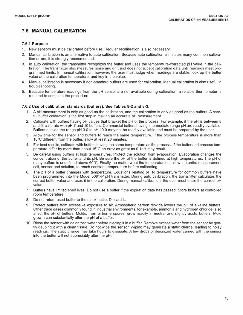
73
MODEL 5081-P pH/ORP SECTION 7.0
CALIBRATION OF pH MEASUREMENTS
7.6.1 Purpose
1. New sensors must be calibrated before use. Regular recalibration is also necessary.
2. Manual calibration is an alternative to auto calibration. Because auto calibration eliminates many common calibra-tion errors, it is strongly recommended.
3. In auto calibration, the transmitter recognizes the buffer and uses the temperature-corrected pH value in the cali-bration. The transmitter also measures noise and drift and does not accept calibration data until readings meet pro-grammed limits. In manual calibration, however, the user must judge when readings are stable, look up the buffervalue at the calibration temperature, and key in the value.
4. Manual calibration is necessary if non-standard buffers are used for calibration. Manual calibration is also useful introubleshooting.
5. Because temperature readings from the pH sensor are not available during calibration, a reliable thermometer isrequired to complete the procedure.
7.6.2 Use of calibration standards (buffers). See Tables 8-2 and 8-3.
1. A pH measurement is only as good as the calibration, and the calibration is only as good as the buffers. A care-ful buffer calibration is the first step in making an accurate pH measurement.
2. Calibrate with buffers having pH values that bracket the pH of the process. For example, if the pH is between 8and 9, calibrate with pH 7 and 10 buffers. Commercial buffers having intermediate range pH are readily available.Buffers outside the range pH 3.0 to pH 10.0 may not be readily available and must be prepared by the user.
3. Allow time for the sensor and buffers to reach the same temperature. If the process temperature is more than10°C different from the buffer, allow at least 20 minutes.
4. For best results, calibrate with buffers having the same temperature as the process. If the buffer and process tem-perature differ by more than about 15°C an error as great as 0.1pH may result.
5. Be careful using buffers at high temperatures. Protect the solution from evaporation. Evaporation changes theconcentration of the buffer and its pH. Be sure the pH of the buffer is defined at high temperatures. The pH ofmany buffers is undefined above 60°C. Finally, no matter what the temperature is, allow the entire measurementcell, sensor and solution, to reach constant temperature before calibrating.
6. The pH of a buffer changes with temperature. Equations relating pH to temperature for common buffers havebeen programmed into the Model 5081-P pH transmitter. during auto calibration, the transmitter calculates thecorrect buffer value and uses it in the calibration. during manual calibration, the user must enter the correct pHvalue.
7. Buffers have limited shelf lives. do not use a buffer if the expiration date has passed. Store buffers at controlledroom temperature.
8. do not return used buffer to the stock bottle. discard it.
9. Protect buffers from excessive exposure to air. Atmospheric carbon dioxide lowers the pH of alkaline buffers.Other trace gases commonly found in industrial environments, for example, ammonia and hydrogen chloride, alsoaffect the pH of buffers. Molds, from airborne spores, grow readily in neutral and slightly acidic buffers. Moldgrowth can substantially alter the pH of a buffer.
10. Rinse the sensor with deionized water before placing it in a buffer. Remove excess water from the sensor by gen-tly daubing it with a clean tissue. do not wipe the sensor. Wiping may generate a static charge, leading to noisyreadings. The static charge may take hours to dissipate. A few drops of deionized water carried with the sensorinto the buffer will not appreciably alter the pH.
7.6 MANUAL CALIBRATION
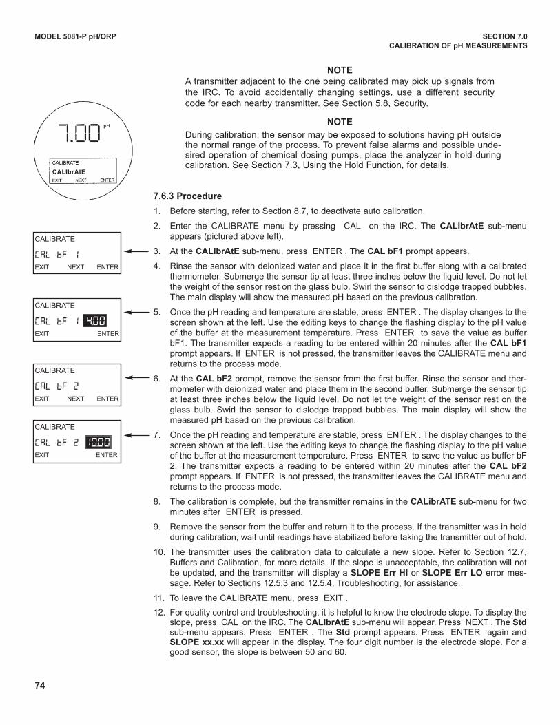
74
7.6.3 Procedure
1. Before starting, refer to Section 8.7, to deactivate auto calibration.
2. Enter the CALIBRATE menu by pressing CAL on the IRC. The CALIbrAtE sub-menuappears (pictured above left).
3. At the CALIbrAtE sub-menu, press ENTER . The CAL bF1 prompt appears.
4. Rinse the sensor with deionized water and place it in the first buffer along with a calibratedthermometer. Submerge the sensor tip at least three inches below the liquid level. do not letthe weight of the sensor rest on the glass bulb. Swirl the sensor to dislodge trapped bubbles.The main display will show the measured pH based on the previous calibration.
5. Once the pH reading and temperature are stable, press ENTER . The display changes to thescreen shown at the left. use the editing keys to change the flashing display to the pH valueof the buffer at the measurement temperature. Press ENTER to save the value as bufferbF1. The transmitter expects a reading to be entered within 20 minutes after the CAL bF1prompt appears. If ENTER is not pressed, the transmitter leaves the CALIBRATE menu andreturns to the process mode.
6. At the CAL bF2 prompt, remove the sensor from the first buffer. Rinse the sensor and ther-mometer with deionized water and place them in the second buffer. Submerge the sensor tipat least three inches below the liquid level. do not let the weight of the sensor rest on theglass bulb. Swirl the sensor to dislodge trapped bubbles. The main display will show themeasured pH based on the previous calibration.
7. Once the pH reading and temperature are stable, press ENTER . The display changes to thescreen shown at the left. use the editing keys to change the flashing display to the pH valueof the buffer at the measurement temperature. Press ENTER to save the value as buffer bF2. The transmitter expects a reading to be entered within 20 minutes after the CAL bF2prompt appears. If ENTER is not pressed, the transmitter leaves the CALIBRATE menu andreturns to the process mode.
8. The calibration is complete, but the transmitter remains in the CALibrATE sub-menu for twominutes after ENTER is pressed.
9. Remove the sensor from the buffer and return it to the process. If the transmitter was in holdduring calibration, wait until readings have stabilized before taking the transmitter out of hold.
10. The transmitter uses the calibration data to calculate a new slope. Refer to Section 12.7,Buffers and Calibration, for more details. If the slope is unacceptable, the calibration will notbe updated, and the transmitter will display a SLOPE Err HI or SLOPE Err LO error mes-sage. Refer to Sections 12.5.3 and 12.5.4, Troubleshooting, for assistance.
11. To leave the CALIBRATE menu, press EXIT .
12. For quality control and troubleshooting, it is helpful to know the electrode slope. To display theslope, press CAL on the IRC. The CALIbrAtE sub-menu will appear. Press NEXT . The Stdsub-menu appears. Press ENTER . The Std prompt appears. Press ENTER again andSLOPE xx.xx will appear in the display. The four digit number is the electrode slope. For agood sensor, the slope is between 50 and 60.
MODEL 5081-P pH/ORP SECTION 7.0
CALIBRATION OF pH MEASUREMENTS
NOTE
A transmitter adjacent to the one being calibrated may pick up signals fromthe IRC. To avoid accidentally changing settings, use a different securitycode for each nearby transmitter. See Section 5.8, Security.
NOTE
during calibration, the sensor may be exposed to solutions having pH outsidethe normal range of the process. To prevent false alarms and possible unde-sired operation of chemical dosing pumps, place the analyzer in hold duringcalibration. See Section 7.3, using the Hold Function, for details.
CALIBRATE
CAL bF 1EXIT NEXT ENTER
CALIBRATE
CAL bF 2EXIT NEXT ENTER
CALIBRATE
CAL bF 2EXIT ENTER
CALIBRATE
CAL bF 1EXIT ENTER
4.00
10.00
75
MODEL 5081-P pH/ORP SECTION 7.0
CALIBRATION OF pH MEASUREMENTS
7.7 MAKING THE TRANSMITTER READING MATCH A SECOND pH METER (STAN-DARDIzATION).
7.7.1 Purpose
1. This section describes how to make the transmitter reading match the reading from a second pH meter. Themeasurement made with the second meter is called the standard pH (pHstd). The process of making the two
readings agree is called standardization.
2. This section also describes how to enter an independently determined slope into the transmitter.
7.7.2 what Happens During Standardization?
1. The user enters the pH reading from a second meter into the transmitter. The transmitter changes the dis-played pH to the new value.
2. The transmitter converts the difference between the pH readings, DpH, into a voltage difference. The voltagedifference, DV, is calculated from the equation:
DV = [0.1984 (t + 273.14)] DpH
where t is the temperature in °C. The voltage difference, called the reference offset, is then added to subse-quent pH cell voltage measurements before the voltage is converted to pH. See Section 13.0 for details onhow the pH meter converts voltage into pH readings.
3. Before the transmitter accepts the offset, it compares the offset with the value (rOFFSt) programmed into thetransmitter in Section 7.3, diagnostic Parameters. If the difference exceeds rOFFSt, the transmitter will notaccept the data and will not update the display to the corrected pH.
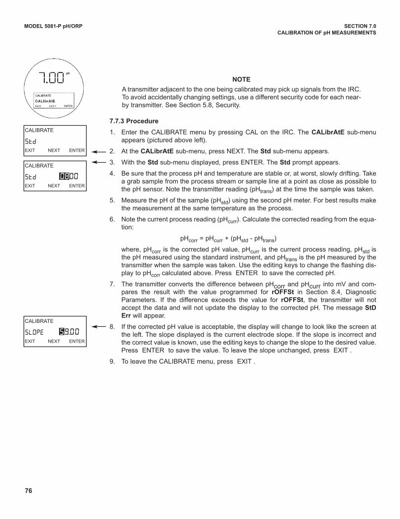
76
MODEL 5081-P pH/ORP SECTION 7.0
CALIBRATION OF pH MEASUREMENTS
CALIBRATE
StdEXIT NEXT ENTER
CALIBRATE
SLOPEEXIT NEXT ENTER
CALIBRATE
StdEXIT NEXT ENTER
08.00
59.00
7.7.3 Procedure
1. Enter the CALIBRATE menu by pressing CAL on the IRC. The CALibrAtE sub-menuappears (pictured above left).
2. At the CALibrAtE sub-menu, press NEXT. The Std sub-menu appears.
3. With the Std sub-menu displayed, press ENTER. The Std prompt appears.
4. Be sure that the process pH and temperature are stable or, at worst, slowly drifting. Takea grab sample from the process stream or sample line at a point as close as possible tothe pH sensor. Note the transmitter reading (pHtrans) at the time the sample was taken.
5. Measure the pH of the sample (pHstd) using the second pH meter. For best results makethe measurement at the same temperature as the process.
6. Note the current process reading (pHcurr). Calculate the corrected reading from the equa-tion:
pHcorr = pHcurr + (pHstd - pHtrans)
where, pHcorr is the corrected pH value, pHcurr is the current process reading, pHstd isthe pH measured using the standard instrument, and pHtrans is the pH measured by thetransmitter when the sample was taken. use the editing keys to change the flashing dis-play to pHcorr calculated above. Press ENTER to save the corrected pH.
7. The transmitter converts the difference between pHcorr and pHcurr into mV and com-pares the result with the value programmed for rOFFSt in Section 8.4, diagnosticParameters. If the difference exceeds the value for rOFFSt, the transmitter will notaccept the data and will not update the display to the corrected pH. The message StD
Err will appear.
8. If the corrected pH value is acceptable, the display will change to look like the screen atthe left. The slope displayed is the current electrode slope. If the slope is incorrect andthe correct value is known, use the editing keys to change the slope to the desired value.Press ENTER to save the value. To leave the slope unchanged, press EXIT .
9. To leave the CALIBRATE menu, press EXIT .
NOTE
A transmitter adjacent to the one being calibrated may pick up signals from the IRC.To avoid accidentally changing settings, use a different security code for each near-by transmitter. See Section 5.8, Security.
77
MODEL 5081-P pH/ORP SECTION 8.0
PROGRAMMING FOR pH MEASUREMENTS
SECTION 8.0PROGRAMMING FOR pH MEASUREMENTS
8.1 General
8.2 Entering and Leaving the Program Menu
8.3 Output Ranging
8.4 Diagnostic Parameters
8.5 Temperature Related Settings
8.6 Display Units
8.7 Buffer Calibration Parameters
8.8 Isopotential Parameters
8.9 Generating a Test Current
8.1 GENERALThis section describes how to do the following:
1. assign pH values to the 4 and 20 mA outputs (for Model 5081-P-HT only),
2. set the current generated by the transmitter during hold,
3. set the current generated by the transmitter when a fault is detected (for Model 5081-P-HT only),
4. change sensor diagnostic limits,
5. enable and disable automatic temperature compensation,
6. change the units of the displayed variables,
7. program a security code,
8. identify buffers for auto calibration,
9. change the transmitter isopotential point,
10. simulate output currents for testing (for Model 5081-P-HT only).
Factory default settings are given in Table 8-1. If default settings are acceptable, the transmitter is ready for calibration.See Section 7.0, Calibration of pH Measurements. Once a setting has been changed, there is no way to automaticallyreset the transmitter to factory defaults. Settings must be returned to default values one at a time. Figure 5-4 shows themenu tree.
8.2 ENTERING AND LEAvING THE PROGRAM MENU
Press PROG on the infrared remote controller (IRC) to enter the Program menu. To save new settings, pressENTER. To leave the Program menu without saving new values, press EXIT . Pressing EXIT with a prompt showingreturns the display to the first prompt in the sub-menu. Pressing EXIT again returns the transmitter to the processdisplay.
If program settings are protected with a security code, pressing PROG or CAL will cause the Id screen to appear.Key in the security code and press ENTER . The first sub-menu will appear. For more information, see Section 5.7,Security.
A transmitter adjacent to the one being programmed may pick up signals from the IRC. To avoid accidentally changingsettings, use a different security code for each nearby transmitter. See Section 5.8, Security, and Section 8.6, displayunits, for details.
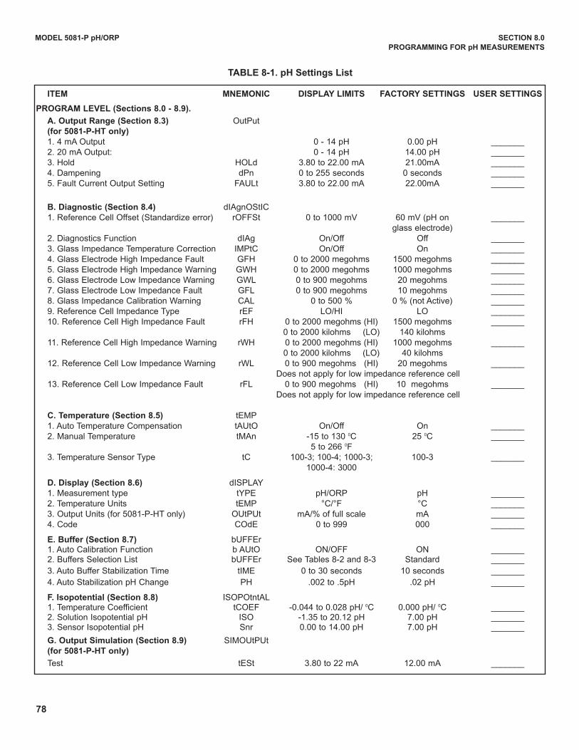
78
MODEL 5081-P pH/ORP SECTION 8.0
PROGRAMMING FOR pH MEASUREMENTS
ITEM MNEMONIC DISPLAy LIMITS FACTORy SETTINGS USER SETTINGS
PROGRAM LEvEL (Sections 8.0 - 8.9).
A. Output Range (Section 8.3) OutPut(for 5081-P-HT only)
1. 4 mA Output 0 - 14 pH 0.00 pH _______2. 20 mA Output: 0 - 14 pH 14.00 pH _______3. Hold HOLd 3.80 to 22.00 mA 21.00mA _______4. dampening dPn 0 to 255 seconds 0 seconds _______5. Fault Current Output Setting FAuLt 3.80 to 22.00 mA 22.00mA _______
B. Diagnostic (Section 8.4) dIAgnOStIC1. Reference Cell Offset (Standardize error) rOFFSt 0 to 1000 mV 60 mV (pH on _______
glass electrode)2. diagnostics Function dIAg On/Off Off _______3. Glass Impedance Temperature Correction IMPtC On/Off On _______4. Glass Electrode High Impedance Fault GFH 0 to 2000 megohms 1500 megohms _______5. Glass Electrode High Impedance Warning GWH 0 to 2000 megohms 1000 megohms _______6. Glass Electrode Low Impedance Warning GWL 0 to 900 megohms 20 megohms _______7. Glass Electrode Low Impedance Fault GFL 0 to 900 megohms 10 megohms _______8. Glass Impedance Calibration Warning CAL 0 to 500 % 0 % (not Active) _______9. Reference Cell Impedance Type rEF LO/HI LO _______10. Reference Cell High Impedance Fault rFH 0 to 2000 megohms (HI) 1500 megohms _______
0 to 2000 kilohms (LO) 140 kilohms11. Reference Cell High Impedance Warning rWH 0 to 2000 megohms (HI) 1000 megohms _______
0 to 2000 kilohms (LO) 40 kilohms12. Reference Cell Low Impedance Warning rWL 0 to 900 megohms (HI) 20 megohms _______
does not apply for low impedance reference cell13. Reference Cell Low Impedance Fault rFL 0 to 900 megohms (HI) 10 megohms _______
does not apply for low impedance reference cell
C. Temperature (Section 8.5) tEMP1. Auto Temperature Compensation tAutO On/Off On _______2. Manual Temperature tMAn -15 to 130 0C 25 0C _______
5 to 266 0F3. Temperature Sensor Type tC 100-3; 100-4; 1000-3; 100-3 _______
1000-4: 3000
D. Display (Section 8.6) dISPLAY1. Measurement type tYPE pH/ORP pH _______2. Temperature units tEMP °C/°F °C _______3. Output units (for 5081-P-HT only) OutPut mA/% of full scale mA _______4. Code COdE 0 to 999 000 _______
E. Buffer (Section 8.7) buFFEr1. Auto Calibration Function b AutO ON/OFF ON _______2. Buffers Selection List buFFEr See Tables 8-2 and 8-3 Standard _______
3. Auto Buffer Stabilization Time tIME 0 to 30 seconds 10 seconds _______
4. Auto Stabilization pH Change PH .002 to .5pH .02 pH _______
F. Isopotential (Section 8.8) ISOPOtntAL1. Temperature Coefficient tCOEF -0.044 to 0.028 pH/ 0C 0.000 pH/ 0C _______2. Solution Isopotential pH ISO -1.35 to 20.12 pH 7.00 pH _______3. Sensor Isopotential pH Snr 0.00 to 14.00 pH 7.00 pH _______
G. Output Simulation (Section 8.9) SIMOutPut(for 5081-P-HT only)
Test tESt 3.80 to 22 mA 12.00 mA _______
TABLE 8-1. pH Settings List
MODEL 5081-P PH/ORP SECTION 8.0
PROGRAMMING FOR pH MEASUREMENTS
8.3 OUTPUT RANGING
8.3.1 Purpose
This section describes how to do the following:
1. assign pH values to the 4 and 20 mA outputs,
2. set the output current generated by the transmitter during hold,
3. set the output current generated by the transmitter when a fault is detected,
4. control the amount of dampening on the output signal.
8.3.2 Definitions
1. CuRRENT OuTPuTS. The transmitter provides a continuous 4 - 20 mA output directly proportional to the measuredpH. Any pH value between 0 and 14 can be assigned to the low output (4 mA) and the high output (20 mA).
2. HOLd. during calibration and maintenance the transmitter output may be outside the normal operating range. Placingthe transmitter on hold prevents false alarms or the unwanted operation of chemical dosing pumps. The transmitteroutput can be programmed to remain at the last value or to generate any current between 3.80 and 22.0 mA. duringhold, the transmitter displays the present pH and temperature. The word HOLd appears in the display.
3. FAuLT. A fault is a system disabling condition. When the transmitter detects a fault, the following happens:
a. The display flashes.
b. The words FAuLT and HOLd appear in the main display.
c. A fault or diagnostic message appears in the temperature/current display area.
d. The output signal remains at the present value or goes to the programmed fault value. Permitted values are between 3.80 and 22.00 mA.
e. If the transmitter is in HOLd when the fault occurs, the output remains at the programmed hold value. To alert theuser that a fault exists, the word FAuLT appears in the main display, and the display flashes. A fault or diagnosticmessage also appears.
f. If the transmitter is simulating an output current when the fault occurs, the transmitter continues to generate thesimulated current. To alert the user that a fault exists, the word FAuLT appears in the display, and the display flash-es.
4. dAMPEN. Output dampening smooths out noisy readings. But it also increases the response time of the output. Toestimate the time (in minutes) required for the output to reach 95% of the final reading following a step change, dividethe setting by 20. Thus, a setting of 140 means that, following a step change, the output takes about seven minutesto reach 95% of final reading. The output dampen setting does not affect the response time of the process display. Themaximum setting is 255.
79
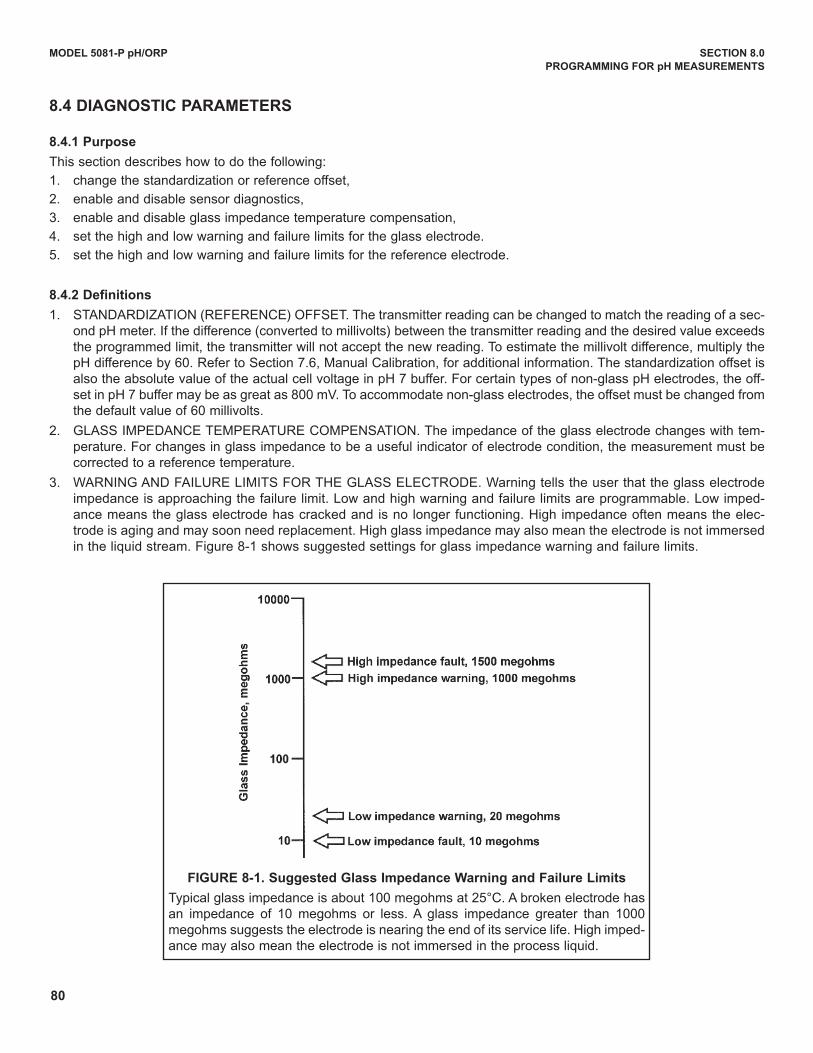
80
MODEL 5081-P pH/ORP SECTION 8.0
PROGRAMMING FOR pH MEASUREMENTS
8.4 DIAGNOSTIC PARAMETERS
8.4.1 Purpose
This section describes how to do the following:
1. change the standardization or reference offset,
2. enable and disable sensor diagnostics,
3. enable and disable glass impedance temperature compensation,
4. set the high and low warning and failure limits for the glass electrode.
5. set the high and low warning and failure limits for the reference electrode.
8.4.2 Definitions
1. STANdARdIZATION (REFERENCE) OFFSET. The transmitter reading can be changed to match the reading of a sec-ond pH meter. If the difference (converted to millivolts) between the transmitter reading and the desired value exceedsthe programmed limit, the transmitter will not accept the new reading. To estimate the millivolt difference, multiply thepH difference by 60. Refer to Section 7.6, Manual Calibration, for additional information. The standardization offset isalso the absolute value of the actual cell voltage in pH 7 buffer. For certain types of non-glass pH electrodes, the off-set in pH 7 buffer may be as great as 800 mV. To accommodate non-glass electrodes, the offset must be changed fromthe default value of 60 millivolts.
2. GLASS IMPEdANCE TEMPERATuRE COMPENSATION. The impedance of the glass electrode changes with tem-perature. For changes in glass impedance to be a useful indicator of electrode condition, the measurement must becorrected to a reference temperature.
3. WARNING ANd FAILuRE LIMITS FOR THE GLASS ELECTROdE. Warning tells the user that the glass electrodeimpedance is approaching the failure limit. Low and high warning and failure limits are programmable. Low imped-ance means the glass electrode has cracked and is no longer functioning. High impedance often means the elec-trode is aging and may soon need replacement. High glass impedance may also mean the electrode is not immersedin the liquid stream. Figure 8-1 shows suggested settings for glass impedance warning and failure limits.
FIGURE 8-1. Suggested Glass Impedance warning and Failure Limits
Typical glass impedance is about 100 megohms at 25°C. A broken electrode hasan impedance of 10 megohms or less. A glass impedance greater than 1000megohms suggests the electrode is nearing the end of its service life. High imped-ance may also mean the electrode is not immersed in the process liquid.
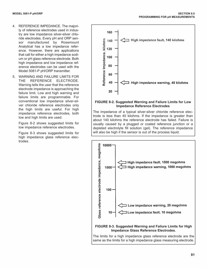
81
MODEL 5081-P pH/ORP SECTION 8.0
PROGRAMMING FOR pH MEASUREMENTS
4. REFERENCE IMPEdANCE. The majori-ty of reference electrodes used in indus-try are low impedance silver-silver chlo-ride electrodes. Every pH and ORP sen-sor manufactured by RosemountAnalytical has a low impedance refer-ence. However, there are applicationsthat call for either a high impedance sodi-um or pH glass reference electrode. Bothhigh impedance and low impedance ref-erence electrodes can be used with theModel 5081-P pH/ORP transmitter.
5. WARNING ANd FAILuRE LIMITS FORTHE REFERENCE ELECTROdE.Warning tells the user that the referenceelectrode impedance is approaching thefailure limit. Low and high warning andfailure limits are programmable. Forconventional low impedance silver-sil-ver chloride reference electrodes onlythe high limits are useful. For highimpedance reference electrodes, bothlow and high limits are used.
Figure 8-2 shows suggested limits forlow impedance reference electrodes.
Figure 8-3 shows suggested limits forhigh impedance glass reference elec-trodes.
FIGURE 8-2. Suggested warning and Failure Limits for Low
Impedance Reference Electrodes
The impedance of a typical silver-silver chloride reference elec-trode is less than 40 kilohms. If the impedance is greater thanabout 140 kilohms the reference electrode has failed. Failure isusually caused by a plugged or coated reference junction or adepleted electrolyte fill solution (gel). The reference impedancewill also be high if the sensor is out of the process liquid.
FIGURE 8-3. Suggested warning and Failure Limits for High
Impedance Glass Reference Electrodes.
The limits for a high impedance glass reference electrode are thesame as the limits for a high impedance glass measuring electrode.
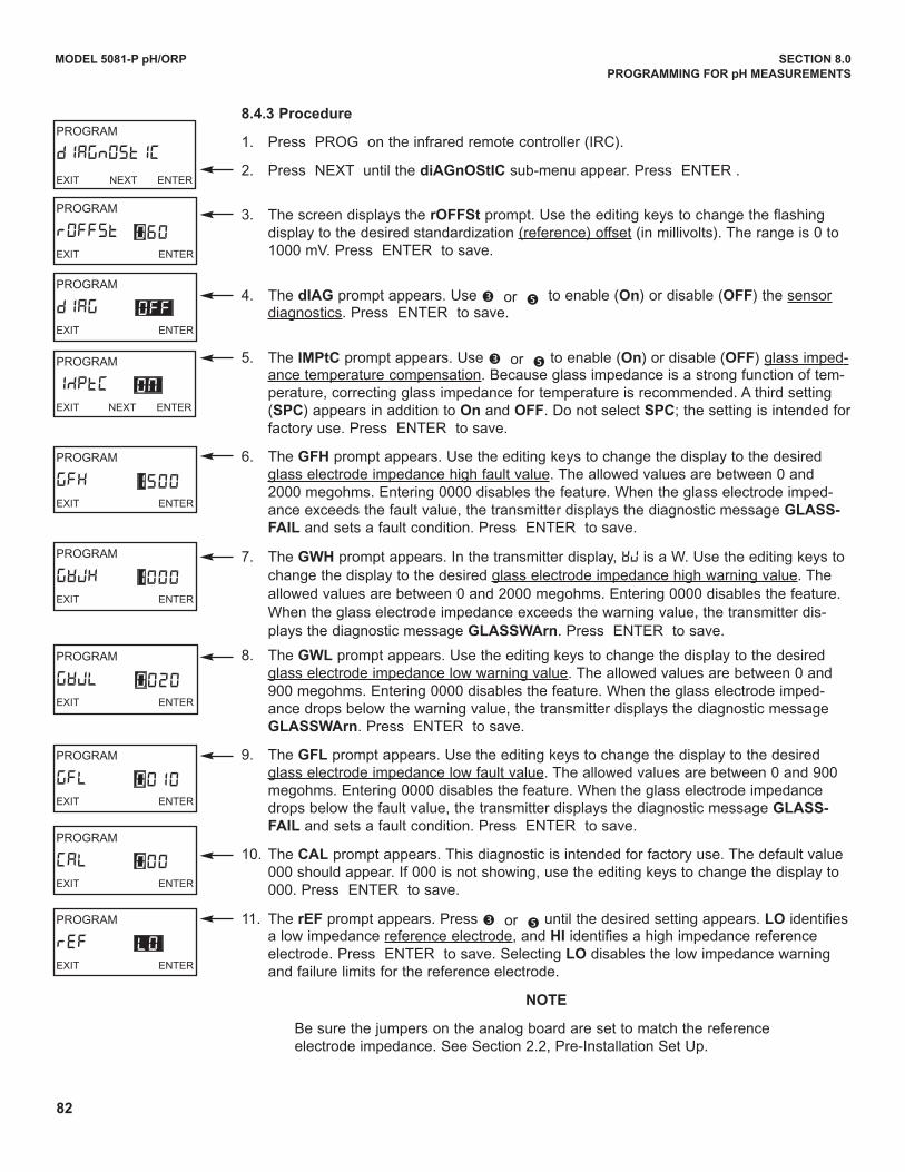
82
8.4.3 Procedure
1. Press PROG on the infrared remote controller (IRC).
2. Press NEXT until the diAGnOStIC sub-menu appear. Press ENTER .
3. The screen displays the rOFFSt prompt. use the editing keys to change the flashingdisplay to the desired standardization (reference) offset (in millivolts). The range is 0 to1000 mV. Press ENTER to save.
4. The dIAG prompt appears. use é or ê to enable (On) or disable (OFF) the sensordiagnostics. Press ENTER to save.
5. The IMPtC prompt appears. use é or ê to enable (On) or disable (OFF) glass imped-ance temperature compensation. Because glass impedance is a strong function of tem-perature, correcting glass impedance for temperature is recommended. A third setting(SPC) appears in addition to On and OFF. do not select SPC; the setting is intended forfactory use. Press ENTER to save.
6. The GFH prompt appears. use the editing keys to change the display to the desiredglass electrode impedance high fault value. The allowed values are between 0 and2000 megohms. Entering 0000 disables the feature. When the glass electrode imped-ance exceeds the fault value, the transmitter displays the diagnostic message GLASS-
FAIL and sets a fault condition. Press ENTER to save.
7. The GwH prompt appears. In the transmitter display, WJ is a W. use the editing keys tochange the display to the desired glass electrode impedance high warning value. Theallowed values are between 0 and 2000 megohms. Entering 0000 disables the feature.When the glass electrode impedance exceeds the warning value, the transmitter dis-plays the diagnostic message GLASSwArn. Press ENTER to save.
8. The GwL prompt appears. use the editing keys to change the display to the desiredglass electrode impedance low warning value. The allowed values are between 0 and900 megohms. Entering 0000 disables the feature. When the glass electrode imped-ance drops below the warning value, the transmitter displays the diagnostic messageGLASSwArn. Press ENTER to save.
9. The GFL prompt appears. use the editing keys to change the display to the desiredglass electrode impedance low fault value. The allowed values are between 0 and 900megohms. Entering 0000 disables the feature. When the glass electrode impedancedrops below the fault value, the transmitter displays the diagnostic message GLASS-
FAIL and sets a fault condition. Press ENTER to save.
10. The CAL prompt appears. This diagnostic is intended for factory use. The default value000 should appear. If 000 is not showing, use the editing keys to change the display to000. Press ENTER to save.
11. The rEF prompt appears. Press é or ê until the desired setting appears. LO identifiesa low impedance reference electrode, and HI identifies a high impedance referenceelectrode. Press ENTER to save. Selecting LO disables the low impedance warningand failure limits for the reference electrode.
NOTE
Be sure the jumpers on the analog board are set to match the referenceelectrode impedance. See Section 2.2, Pre-Installation Set up.
MODEL 5081-P pH/ORP SECTION 8.0
PROGRAMMING FOR pH MEASUREMENTS
PROGRAM
IMPtCEXIT NEXT ENTER
ON
PROGRAM
GFHEXIT ENTER
1500
PROGRAM
GWJHEXIT ENTER
1000
PROGRAM
GWJLEXIT ENTER
0020
PROGRAM
GFLEXIT ENTER
0010
PROGRAM
rOFFStEXIT ENTER
PROGRAM
dIAGnOSTIC
EXIT NEXT ENTER
060
PROGRAM
dIAGEXIT ENTER
OFF
PROGRAM
rEFEXIT ENTER
LO
PROGRAM
CALEXIT ENTER
000
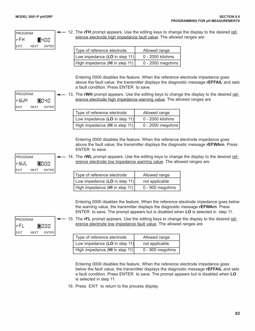
83
12. The rFH prompt appears. use the editing keys to change the display to the desired ref-erence electrode high impedance fault value. The allowed ranges are
Type of reference electrode Allowed range
Low impedance (LO in step 11) 0 - 2000 kilohms
High impedance (HI in step 11) 0 - 2000 megohms
Entering 0000 disables the feature. When the reference electrode impedance goesabove the fault value, the transmitter displays the diagnostic message rEFFAIL and setsa fault condition. Press ENTER to save.
13. The rwH prompt appears. use the editing keys to change the display to the desired ref-erence electrode high impedance warning value. The allowed ranges are
Type of reference electrode Allowed range
Low impedance (LO in step 11) 0 - 2000 kilohms
High impedance (HI in step 11) 0 - 2000 megohms
Entering 0000 disables the feature. When the reference electrode impedance goesabove the fault value, the transmitter displays the diagnostic message rEFwArn. PressENTER to save.
14. The rwL prompt appears. use the editing keys to change the display to the desired ref-erence electrode low impedance warning value. The allowed ranges are
Type of reference electrode Allowed range
Low impedance (LO in step 11) not applicable
High impedance (HI in step 11) 0 - 900 megohms
Entering 0000 disables the feature. When the reference electrode impedance goes belowthe warning value, the transmitter displays the diagnostic message rEFwArn. PressENTER to save. The prompt appears but is disabled when LO is selected in step 11.
15. The rFL prompt appears. use the editing keys to change the display to the desired ref-erence electrode low impedance fault value. The allowed ranges are
Type of reference electrode Allowed range
Low impedance (LO in step 11) not applicable
High impedance (HI in step 11) 0 - 900 megohms
Entering 0000 disables the feature. When the reference electrode impedance goesbelow the fault value, the transmitter displays the diagnostic message rEFFAIL and setsa fault condition. Press ENTER to save. The prompt appears but is disabled when LO
is selected in step 11.
16. Press EXIT to return to the process display.
MODEL 5081-P pH/ORP SECTION 8.0
PROGRAMMING FOR pH MEASUREMENTS
PROGRAM
rFHEXIT NEXT ENTER
1400
PROGRAM
rWJHEXIT NEXT ENTER
0040
PROGRAM
rWJLEXIT NEXT ENTER
0000
PROGRAM
rFLEXIT NEXT ENTER
0000
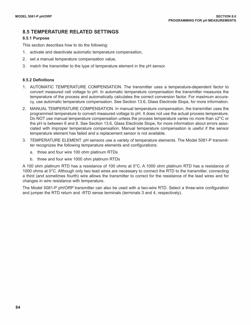
84
MODEL 5081-P pH/ORP SECTION 8.0
PROGRAMMING FOR pH MEASUREMENTS
8.5 TEMPERATURE RELATED SETTINGS
8.5.1 Purpose
This section describes how to do the following:
1. activate and deactivate automatic temperature compensation,
2. set a manual temperature compensation value,
3. match the transmitter to the type of temperature element in the pH sensor.
8.5.2 Definitions
1. AuTOMATIC TEMPERATuRE COMPENSATION. The transmitter uses a temperature-dependent factor toconvert measured cell voltage to pH. In automatic temperature compensation the transmitter measures thetemperature of the process and automatically calculates the correct conversion factor. For maximum accura-cy, use automatic temperature compensation. See Section 13.6, Glass Electrode Slope, for more information.
2. MANuAL TEMPERATuRE COMPENSATION. In manual temperature compensation, the transmitter uses theprogrammed temperature to convert measured voltage to pH. It does not use the actual process temperature.do NOT use manual temperature compensation unless the process temperature varies no more than ±2°C orthe pH is between 6 and 8. See Section 13.6, Glass Electrode Slope, for more information about errors asso-ciated with improper temperature compensation. Manual temperature compensation is useful if the sensortemperature element has failed and a replacement sensor is not available.
3. TEMPERATuRE ELEMENT. pH sensors use a variety of temperature elements. The Model 5081-P transmit-ter recognizes the following temperature elements and configurations:
a. three and four wire 100 ohm platinum RTds
b. three and four wire 1000 ohm platinum RTds
A 100 ohm platinum RTd has a resistance of 100 ohms at 0°C. A 1000 ohm platinum RTd has a resistance of1000 ohms at 0°C. Although only two lead wires are necessary to connect the RTd to the transmitter, connectinga third (and sometimes fourth) wire allows the transmitter to correct for the resistance of the lead wires and forchanges in wire resistance with temperature.
The Model 5081-P pH/ORP transmitter can also be used with a two-wire RTd. Select a three-wire configurationand jumper the RTd return and -RTd sense terminals (terminals 3 and 4, respectively).
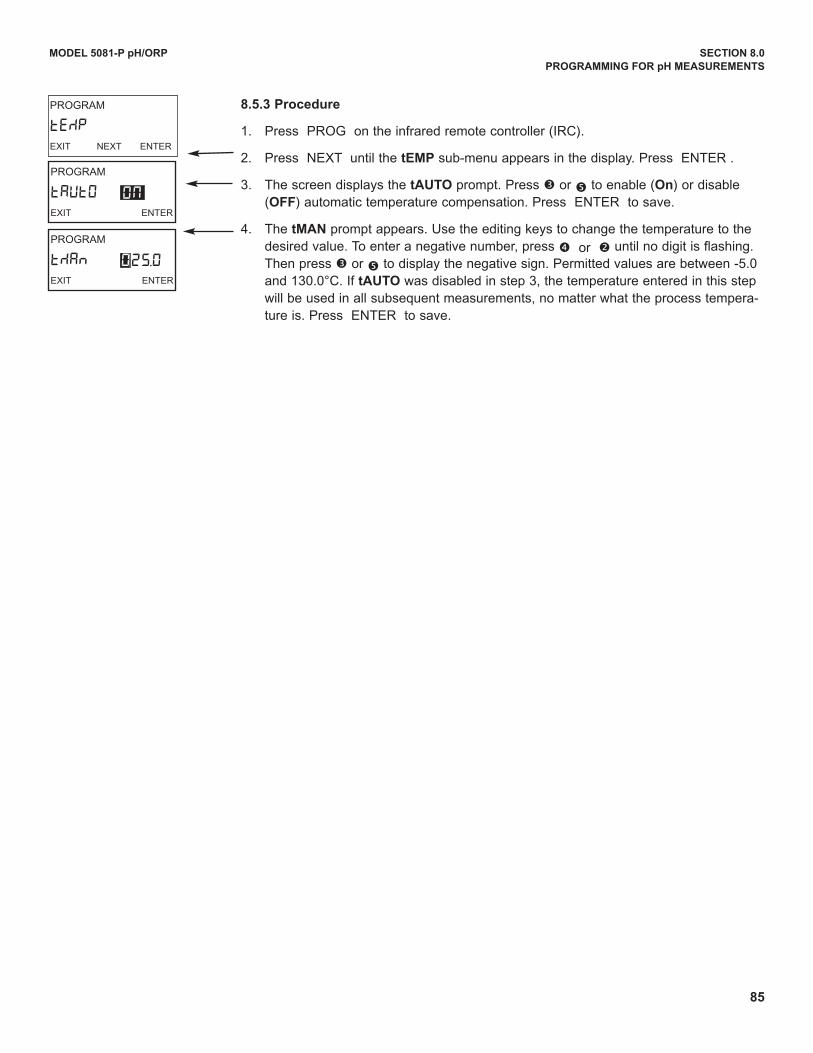
85
MODEL 5081-P pH/ORP SECTION 8.0
PROGRAMMING FOR pH MEASUREMENTS
8.5.3 Procedure
1. Press PROG on the infrared remote controller (IRC).
2. Press NEXT until the tEMP sub-menu appears in the display. Press ENTER .
3. The screen displays the tAUTO prompt. Press é or ê to enable (On) or disable(OFF) automatic temperature compensation. Press ENTER to save.
4. The tMAN prompt appears. use the editing keys to change the temperature to thedesired value. To enter a negative number, press è or ç until no digit is flashing.Then press é or ê to display the negative sign. Permitted values are between -5.0and 130.0°C. If tAUTO was disabled in step 3, the temperature entered in this stepwill be used in all subsequent measurements, no matter what the process tempera-ture is. Press ENTER to save.
PROGRAM
tAUtOEXIT ENTER
ON
PROGRAM
tMAnEXIT ENTER
025.0
PROGRAM
tEMPEXIT NEXT ENTER
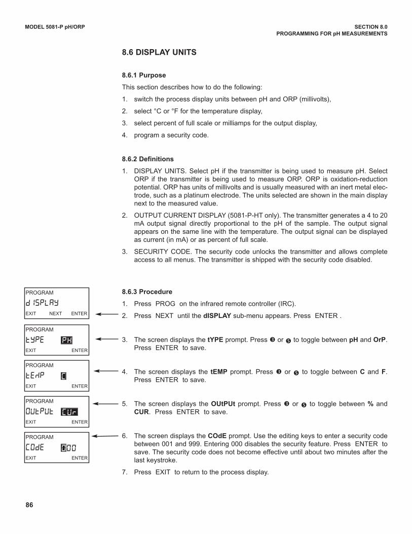
86
MODEL 5081-P pH/ORP SECTION 8.0
PROGRAMMING FOR pH MEASUREMENTS
8.6 DISPLAy UNITS
8.6.1 Purpose
This section describes how to do the following:
1. switch the process display units between pH and ORP (millivolts),
2. select °C or °F for the temperature display,
3. select percent of full scale or milliamps for the output display,
4. program a security code.
8.6.2 Definitions
1. dISPLAY uNITS. Select pH if the transmitter is being used to measure pH. SelectORP if the transmitter is being used to measure ORP. ORP is oxidation-reductionpotential. ORP has units of millivolts and is usually measured with an inert metal elec-trode, such as a platinum electrode. The units selected are shown in the main displaynext to the measured value.
2. OuTPuT CuRRENT dISPLAY (5081-P-HT only). The transmitter generates a 4 to 20mA output signal directly proportional to the pH of the sample. The output signalappears on the same line with the temperature. The output signal can be displayedas current (in mA) or as percent of full scale.
3. SECuRITY COdE. The security code unlocks the transmitter and allows completeaccess to all menus. The transmitter is shipped with the security code disabled.
8.6.3 Procedure
1. Press PROG on the infrared remote controller (IRC).
2. Press NEXT until the dISPLAy sub-menu appears. Press ENTER .
3. The screen displays the tyPE prompt. Press é or ê to toggle between pH and OrP.Press ENTER to save.
4. The screen displays the tEMP prompt. Press é or ê to toggle between C and F.Press ENTER to save.
5. The screen displays the OUtPUt prompt. Press é or ê to toggle between % andCUR. Press ENTER to save.
6. The screen displays the COdE prompt. use the editing keys to enter a security codebetween 001 and 999. Entering 000 disables the security feature. Press ENTER tosave. The security code does not become effective until about two minutes after thelast keystroke.
7. Press EXIT to return to the process display.
PROGRAM
OUtPUtEXIT ENTER
CUR
PROGRAM
CODEEXIT ENTER
000
PROGRAM
tYPEEXIT ENTER
PH
PROGRAM
tEMPEXIT ENTER
C
PROGRAM
dISPLAYEXIT NEXT ENTER
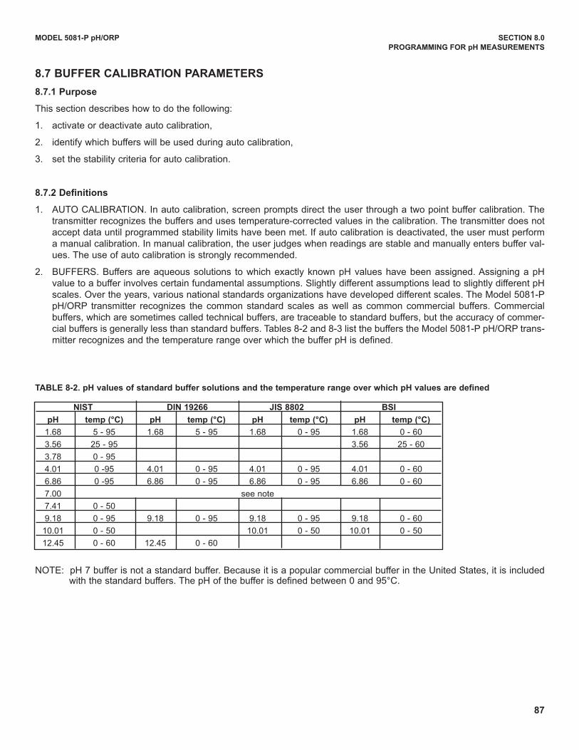
87
MODEL 5081-P pH/ORP SECTION 8.0
PROGRAMMING FOR pH MEASUREMENTS
8.7 BUFFER CALIBRATION PARAMETERS
8.7.1 Purpose
This section describes how to do the following:
1. activate or deactivate auto calibration,
2. identify which buffers will be used during auto calibration,
3. set the stability criteria for auto calibration.
8.7.2 Definitions
1. AuTO CALIBRATION. In auto calibration, screen prompts direct the user through a two point buffer calibration. Thetransmitter recognizes the buffers and uses temperature-corrected values in the calibration. The transmitter does notaccept data until programmed stability limits have been met. If auto calibration is deactivated, the user must performa manual calibration. In manual calibration, the user judges when readings are stable and manually enters buffer val-ues. The use of auto calibration is strongly recommended.
2. BuFFERS. Buffers are aqueous solutions to which exactly known pH values have been assigned. Assigning a pHvalue to a buffer involves certain fundamental assumptions. Slightly different assumptions lead to slightly different pHscales. Over the years, various national standards organizations have developed different scales. The Model 5081-PpH/ORP transmitter recognizes the common standard scales as well as common commercial buffers. Commercialbuffers, which are sometimes called technical buffers, are traceable to standard buffers, but the accuracy of commer-cial buffers is generally less than standard buffers. Tables 8-2 and 8-3 list the buffers the Model 5081-P pH/ORP trans-mitter recognizes and the temperature range over which the buffer pH is defined.
NOTE: pH 7 buffer is not a standard buffer. Because it is a popular commercial buffer in the united States, it is includedwith the standard buffers. The pH of the buffer is defined between 0 and 95°C.
NIST DIN 19266 JIS 8802 BSI
pH temp (°C) pH temp (°C) pH temp (°C) pH temp (°C)
1.68 5 - 95 1.68 5 - 95 1.68 0 - 95 1.68 0 - 60
3.56 25 - 95 3.56 25 - 60
3.78 0 - 95
4.01 0 -95 4.01 0 - 95 4.01 0 - 95 4.01 0 - 60
6.86 0 -95 6.86 0 - 95 6.86 0 - 95 6.86 0 - 60
7.00 see note
7.41 0 - 50
9.18 0 - 95 9.18 0 - 95 9.18 0 - 95 9.18 0 - 60
10.01 0 - 50 10.01 0 - 50 10.01 0 - 50
12.45 0 - 60 12.45 0 - 60
TABLE 8-2. pH values of standard buffer solutions and the temperature range over which pH values are defined
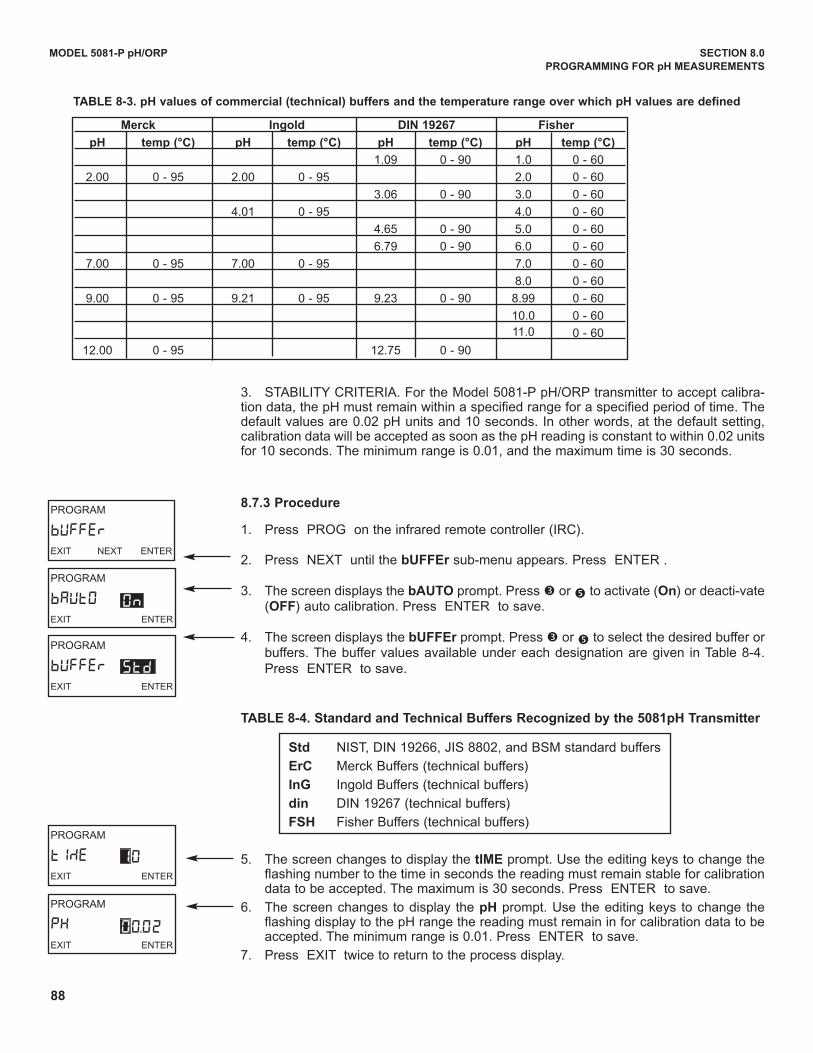
88
MODEL 5081-P pH/ORP SECTION 8.0
PROGRAMMING FOR pH MEASUREMENTS
3. STABILITY CRITERIA. For the Model 5081-P pH/ORP transmitter to accept calibra-tion data, the pH must remain within a specified range for a specified period of time. Thedefault values are 0.02 pH units and 10 seconds. In other words, at the default setting,calibration data will be accepted as soon as the pH reading is constant to within 0.02 unitsfor 10 seconds. The minimum range is 0.01, and the maximum time is 30 seconds.
8.7.3 Procedure
1. Press PROG on the infrared remote controller (IRC).
2. Press NEXT until the bUFFEr sub-menu appears. Press ENTER .
3. The screen displays the bAUTO prompt. Press é or ê to activate (On) or deacti-vate(OFF) auto calibration. Press ENTER to save.
4. The screen displays the bUFFEr prompt. Press é or ê to select the desired buffer orbuffers. The buffer values available under each designation are given in Table 8-4.Press ENTER to save.
TABLE 8-4. Standard and Technical Buffers Recognized by the 5081pH Transmitter
Std NIST, dIN 19266, JIS 8802, and BSM standard buffers
ErC Merck Buffers (technical buffers)
InG Ingold Buffers (technical buffers)
din dIN 19267 (technical buffers)
FSH Fisher Buffers (technical buffers)
5. The screen changes to display the tIME prompt. use the editing keys to change theflashing number to the time in seconds the reading must remain stable for calibrationdata to be accepted. The maximum is 30 seconds. Press ENTER to save.
6. The screen changes to display the pH prompt. use the editing keys to change theflashing display to the pH range the reading must remain in for calibration data to beaccepted. The minimum range is 0.01. Press ENTER to save.
7. Press EXIT twice to return to the process display.
Merck Ingold DIN 19267 Fisher
pH temp (°C) pH temp (°C) pH temp (°C) pH temp (°C)
1.09 0 - 90 1.0 0 - 60
2.00 0 - 95 2.00 0 - 95 2.0 0 - 60
3.06 0 - 90 3.0 0 - 60
4.01 0 - 95 4.0 0 - 60
4.65 0 - 90 5.0 0 - 60
6.79 0 - 90 6.0 0 - 60
7.00 0 - 95 7.00 0 - 95 7.0 0 - 60
8.0 0 - 60
9.00 0 - 95 9.21 0 - 95 9.23 0 - 90 8.99 0 - 60
10.0 0 - 60
11.0 0 - 60
12.00 0 - 95 12.75 0 - 90
TABLE 8-3. pH values of commercial (technical) buffers and the temperature range over which pH values are defined
PROGRAM
bAUtOEXIT ENTER
On
PROGRAM
bUFFErEXIT ENTER
Std
PROGRAM
bUFFErEXIT NEXT ENTER
PROGRAM
tIMEEXIT ENTER
10
PROGRAM
pHEXIT ENTER
00.02
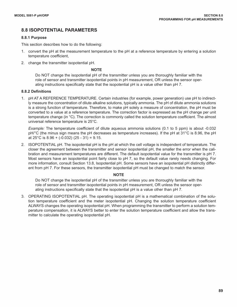
89
MODEL 5081-P pH/ORP SECTION 8.0
PROGRAMMING FOR pH MEASUREMENTS
8.8 ISOPOTENTIAL PARAMETERS
8.8.1 Purpose
This section describes how to do the following:
1. convert the pH at the measurement temperature to the pH at a reference temperature by entering a solutiontemperature coefficient,
2. change the transmitter isopotential pH.
NOTE
do NOT change the isopotential pH of the transmitter unless you are thoroughly familiar with therole of sensor and transmitter isopotential points in pH measurement, OR unless the sensor oper-ating instructions specifically state that the isopotential pH is a value other than pH 7.
8.8.2 Definitions
1. pH AT A REFERENCE TEMPERATuRE. Certain industries (for example, power generation) use pH to indirect-ly measure the concentration of dilute alkaline solutions, typically ammonia. The pH of dilute ammonia solutionsis a strong function of temperature. Therefore, to make pH solely a measure of concentration, the pH must beconverted to a value at a reference temperature. The correction factor is expressed as the pH change per unittemperature change (in °C). The correction is commonly called the solution temperature coefficient. The almostuniversal reference temperature is 25°C.
Example: The temperature coefficient of dilute aqueous ammonia solutions (0.1 to 5 ppm) is about -0.032pH/°C (the minus sign means the pH decreases as temperature increases). If the pH at 31°C is 8.96, the pHat 25°C is 8.96 + (-0.032) (25 - 31) = 9.15.
2. ISOPOTENTIAL pH. The isopotential pH is the pH at which the cell voltage is independent of temperature. Thecloser the agreement between the transmitter and sensor isopotential pH, the smaller the error when the cali-bration and measurement temperatures are different. The default isopotential value for the transmitter is pH 7.Most sensors have an isopotential point fairly close to pH 7, so the default value rarely needs changing. Formore information, consult Section 13.8, Isopotential pH. Some sensors have an isopotential pH distinctly differ-ent from pH 7. For these sensors, the transmitter isopotential pH must be changed to match the sensor.
NOTE
do NOT change the isopotential pH of the transmitter unless you are thoroughly familiar with therole of sensor and transmitter isopotential points in pH measurement, OR unless the sensor oper-ating instructions specifically state that the isopotential pH is a value other than pH 7.
3. OPERATING ISOPOTENTIAL pH. The operating isopotential pH is a mathematical combination of the solu-tion temperature coefficient and the meter isopotential pH. Changing the solution temperature coefficientALWAYS changes the operating isopotential pH. When programming the transmitter to perform a solution tem-perature compensation, it is ALWAYS better to enter the solution temperature coefficient and allow the trans-mitter to calculate the operating isopotential pH.
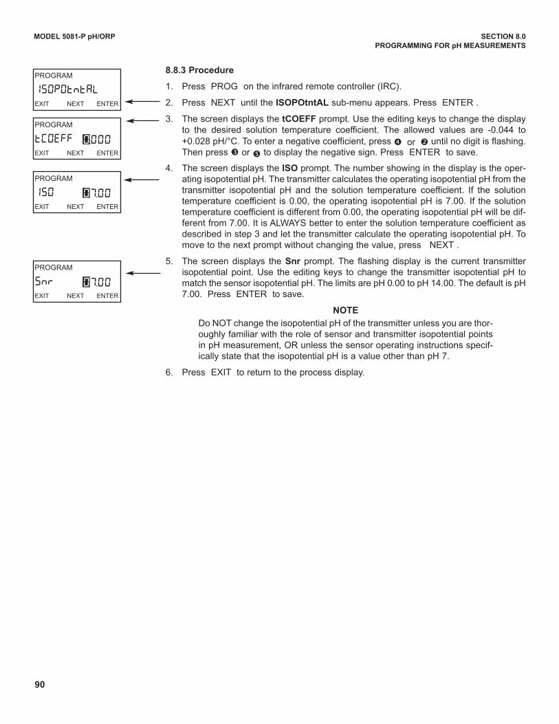
90
MODEL 5081-P pH/ORP SECTION 8.0
PROGRAMMING FOR pH MEASUREMENTS
8.8.3 Procedure
1. Press PROG on the infrared remote controller (IRC).
2. Press NEXT until the ISOPOtntAL sub-menu appears. Press ENTER .
3. The screen displays the tCOEFF prompt. use the editing keys to change the displayto the desired solution temperature coefficient. The allowed values are -0.044 to+0.028 pH/°C. To enter a negative coefficient, press è or ç until no digit is flashing.Then press é or ê to display the negative sign. Press ENTER to save.
4. The screen displays the ISO prompt. The number showing in the display is the oper-ating isopotential pH. The transmitter calculates the operating isopotential pH from thetransmitter isopotential pH and the solution temperature coefficient. If the solutiontemperature coefficient is 0.00, the operating isopotential pH is 7.00. If the solutiontemperature coefficient is different from 0.00, the operating isopotential pH will be dif-ferent from 7.00. It is ALWAYS better to enter the solution temperature coefficient asdescribed in step 3 and let the transmitter calculate the operating isopotential pH. Tomove to the next prompt without changing the value, press NEXT .
5. The screen displays the Snr prompt. The flashing display is the current transmitterisopotential point. use the editing keys to change the transmitter isopotential pH tomatch the sensor isopotential pH. The limits are pH 0.00 to pH 14.00. The default is pH7.00. Press ENTER to save.
NOTE
do NOT change the isopotential pH of the transmitter unless you are thor-oughly familiar with the role of sensor and transmitter isopotential pointsin pH measurement, OR unless the sensor operating instructions specif-ically state that the isopotential pH is a value other than pH 7.
6. Press EXIT to return to the process display.
PROGRAM
SnrEXIT NEXT ENTER
07.00
PROGRAM
ISOPOtntALEXIT NEXT ENTER
PROGRAM
tCOEFFEXIT NEXT ENTER
0.000
PROGRAM
ISOEXIT NEXT ENTER
07.00
PROGRAM
tEStEXIT ENTER
12.00
PROGRAM
dPnEXIT ENTER
000
MODEL 5081-P PH/ORP SECTION 8.0
PROGRAMMING FOR pH MEASUREMENTS
8.9 GENERATING A TEST CURRENT (for 5081-P-HT only)
8.9.1 Purpose
This section describes how to generate output currents for testing recorders and data han-dling systems.
8.9.2 what happens while the transmitter is generating a test current?
1. The output current goes to the programmed test value and remains there until the TEST function is disabled.
2. The main display continues to show the pH of the process stream. The word HOLdappears in the display.
3. The test current value supersedes both the HOLd value and the FAuLT value.
4. If a fault occurs while the transmitter is generating the test current, the word fault appears in the display and the display flashes.
8.9.3 Procedure
1. Press PROG on the infrared remote controller (IRC). OUtPUt will appear. PressENTER
2. Press NEXT until the dPn sub-menu appears. Press ENTER .
3. The tESt prompt appears. use the editing keys to change the number to the desiredvalue. The allowed values are between 3.80 mA and 22.00 mA.
4. Press ENTER to start the test current. HOLD will appear o the left side of the screen.
5. To end the test current, press EXIT.
6. Press EXIT to return to the process display.
91
92
MODEL 5081-P pH/ORP SECTION 9.0
CALIBRATION OF ORP MEASUREMENTS
SECTION 9.0CALIBRATION OF ORP MEASUREMENTS
9.1 General
9.2 Entering and Leaving the Calibrate Menu
9.3 Using the Hold Function
9.4 Temperature Calibration
9.5 Standardization
9.1 GENERAL
The Calibrate menu allows the user to calibrate the ORP and temperature response of the sensor.
The ORP calibration is a one-point standardization against an ORP standard. The temperature calibration is aone-point standardization against a reference thermometer. Prompts guide the user through the calibration proce-dures.
9.2. ENTERING AND LEAvING THE CALIBRATE MENU
Press CAL on the infrared remote controller (IRC) to enter the Calibrate menu. To store new settings in memory,press ENTER . To leave the Calibrate menu without storing new values, press EXIT. Pressing EXIT with a promptshowing returns the display to the first prompt in the sub-menu. Pressing EXIT a second time returns the trans-mitter to the process display.
If program settings are protected with a security code, pressing PROG or CAL will cause the Id screen to appear.Key in the security code and press ENTER. The first sub-menu will appear. For more information, see Section 5.8,Security.
A transmitter adjacent to the one being calibrated may pick up signals from the IRC. To avoid accidentally chang-ing settings, use a different security code for each nearby transmitter.
9.3 USING THE HOLD FUNCTION
during calibration, the sensor may be exposed to solutions having an ORP outside the normal range of theprocess. To prevent false alarms and possible undesired operation of chemical dosing pumps, place the transmit-ter in hold during calibration. Activating HOLd keeps the transmitter output at the last value or sends the output toa previously determined value.
After calibration, reinstall the sensor in the process stream. Wait until readings have stabilized before deactivatingHold.
To activate or deactivate Hold, do the following:
1. Press HOLd on the IRC.
2. The HoLd prompt appears in the display. Press é or ê to toggle the Hold function between On and OFF.
3. Press ENTER to save the setting.
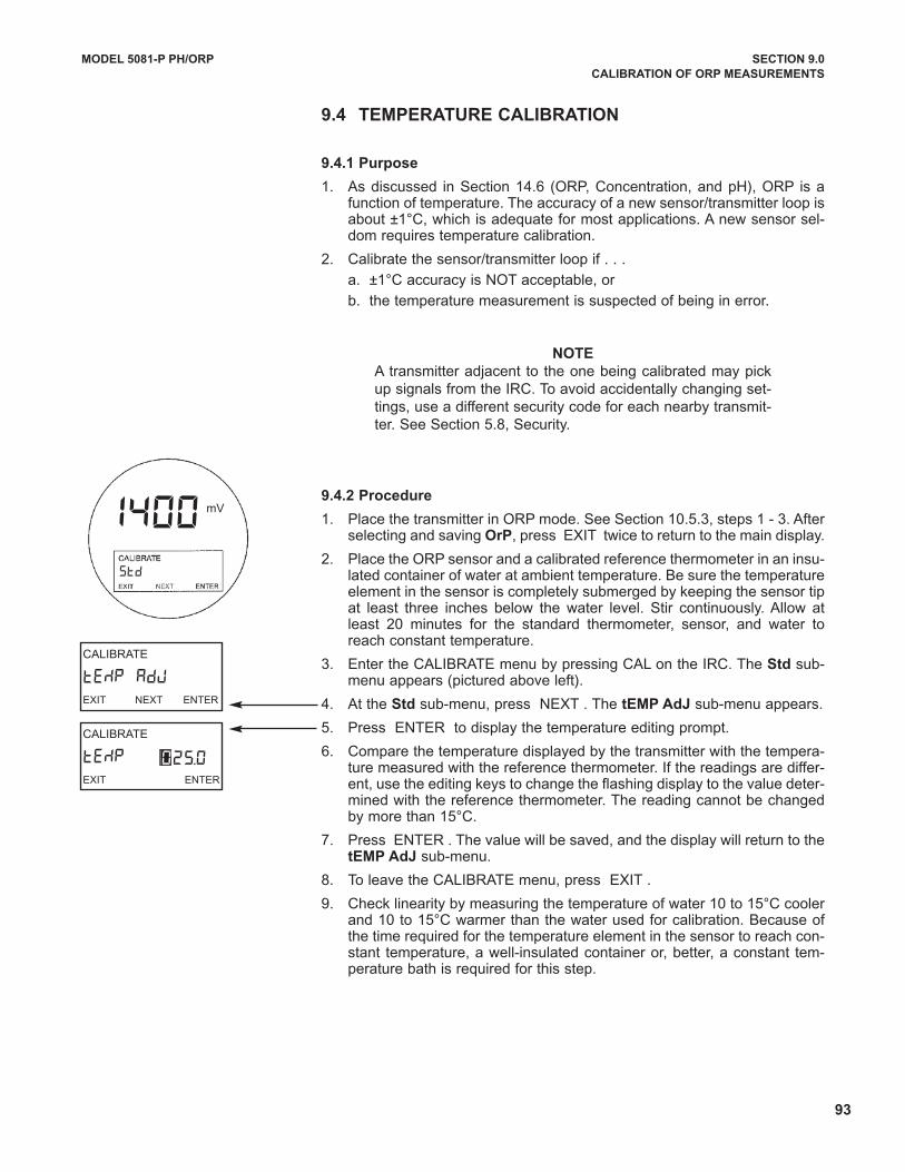
93
CALIBRATE
tEMP AdJEXIT NEXT ENTER
CALIBRATE
tEMP EXIT ENTER
025.0
9.4 TEMPERATURE CALIBRATION
9.4.1 Purpose
1. As discussed in Section 14.6 (ORP, Concentration, and pH), ORP is afunction of temperature. The accuracy of a new sensor/transmitter loop isabout ±1°C, which is adequate for most applications. A new sensor sel-dom requires temperature calibration.
2. Calibrate the sensor/transmitter loop if . . .
a. ±1°C accuracy is NOT acceptable, or
b. the temperature measurement is suspected of being in error.
NOTE
A transmitter adjacent to the one being calibrated may pickup signals from the IRC. To avoid accidentally changing set-tings, use a different security code for each nearby transmit-ter. See Section 5.8, Security.
9.4.2 Procedure
1. Place the transmitter in ORP mode. See Section 10.5.3, steps 1 - 3. Afterselecting and saving OrP, press EXIT twice to return to the main display.
2. Place the ORP sensor and a calibrated reference thermometer in an insu-lated container of water at ambient temperature. Be sure the temperatureelement in the sensor is completely submerged by keeping the sensor tipat least three inches below the water level. Stir continuously. Allow atleast 20 minutes for the standard thermometer, sensor, and water toreach constant temperature.
3. Enter the CALIBRATE menu by pressing CAL on the IRC. The Std sub-menu appears (pictured above left).
4. At the Std sub-menu, press NEXT . The tEMP AdJ sub-menu appears.
5. Press ENTER to display the temperature editing prompt.
6. Compare the temperature displayed by the transmitter with the tempera-ture measured with the reference thermometer. If the readings are differ-ent, use the editing keys to change the flashing display to the value deter-mined with the reference thermometer. The reading cannot be changedby more than 15°C.
7. Press ENTER . The value will be saved, and the display will return to thetEMP AdJ sub-menu.
8. To leave the CALIBRATE menu, press EXIT .
9. Check linearity by measuring the temperature of water 10 to 15°C coolerand 10 to 15°C warmer than the water used for calibration. Because ofthe time required for the temperature element in the sensor to reach con-stant temperature, a well-insulated container or, better, a constant tem-perature bath is required for this step.
Std
MODEL 5081-P PH/ORP SECTION 9.0
CALIBRATION OF ORP MEASUREMENTS
1400 mV
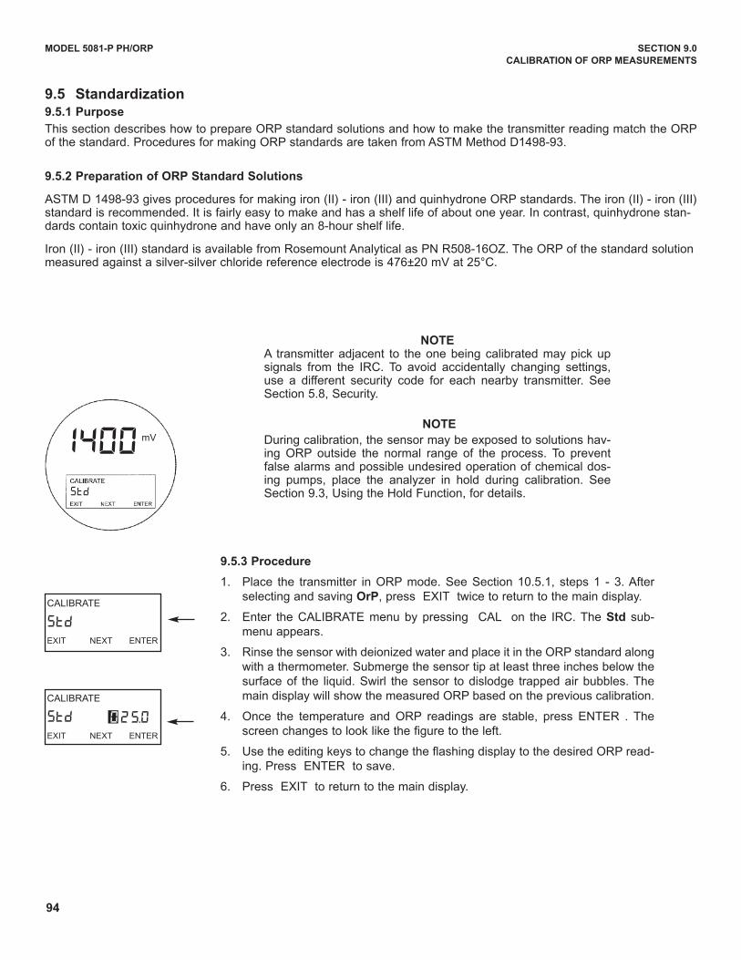
94
9.5.3 Procedure
1. Place the transmitter in ORP mode. See Section 10.5.1, steps 1 - 3. Afterselecting and saving OrP, press EXIT twice to return to the main display.
2. Enter the CALIBRATE menu by pressing CAL on the IRC. The Std sub-menu appears.
3. Rinse the sensor with deionized water and place it in the ORP standard alongwith a thermometer. Submerge the sensor tip at least three inches below thesurface of the liquid. Swirl the sensor to dislodge trapped air bubbles. Themain display will show the measured ORP based on the previous calibration.
4. Once the temperature and ORP readings are stable, press ENTER . Thescreen changes to look like the figure to the left.
5. use the editing keys to change the flashing display to the desired ORP read-ing. Press ENTER to save.
6. Press EXIT to return to the main display.
NOTEA transmitter adjacent to the one being calibrated may pick upsignals from the IRC. To avoid accidentally changing settings,use a different security code for each nearby transmitter. SeeSection 5.8, Security.
NOTE
during calibration, the sensor may be exposed to solutions hav-ing ORP outside the normal range of the process. To preventfalse alarms and possible undesired operation of chemical dos-ing pumps, place the analyzer in hold during calibration. SeeSection 9.3, using the Hold Function, for details.
CALIBRATE
StdEXIT NEXT ENTER
CALIBRATE
StdEXIT NEXT ENTER
025.0
Std
9.5 Standardization9.5.1 Purpose
This section describes how to prepare ORP standard solutions and how to make the transmitter reading match the ORPof the standard. Procedures for making ORP standards are taken from ASTM Method d1498-93.
9.5.2 Preparation of ORP Standard Solutions
ASTM d 1498-93 gives procedures for making iron (II) - iron (III) and quinhydrone ORP standards. The iron (II) - iron (III)standard is recommended. It is fairly easy to make and has a shelf life of about one year. In contrast, quinhydrone stan-dards contain toxic quinhydrone and have only an 8-hour shelf life.
Iron (II) - iron (III) standard is available from Rosemount Analytical as PN R508-16OZ. The ORP of the standard solutionmeasured against a silver-silver chloride reference electrode is 476±20 mV at 25°C.
MODEL 5081-P PH/ORP SECTION 9.0
CALIBRATION OF ORP MEASUREMENTS
1400 mV
95
10.1 GENERAL
This section describes how to do the following:
1. assign ORP values to the 4 and 20 mA outputs (for Model 5081-P-HT only),
2. set the current generated by the transmitter during hold (for Model 5081-P-HT only),
3. set the current generated by the transmitter when a fault is detected (for Model 5081-P-HT only),
4. change sensor diagnostic limits,
5. change the units of the displayed variables,
6. program a security code,
7. simulate output currents for testing (for Model 5081-P-HT only).
Factory default settings are given in Table 10-1. If default settings are acceptable, the transmitter is ready for cal-ibration. See Section 9.0, Calibration of ORP Measurements. There is no way to automatically reset the transmit-ter to factory defaults. Settings must be returned to default values one at a time. Figure 5-5 shows the menu tree.
10.2 ENTERING AND LEAvING THE PROGRAM MENU
Press PROG on the infrared remote controller (IRC) to enter the Program menu. To save new settings, pressENTER . To leave the Program menu without saving new values, press EXIT . Pressing EXIT with a promptshowing returns the display to the first prompt in the sub-menu. Pressing EXIT again returns the transmitterto the process display.
If program settings are protected with a security code, pressing PROG or CAL will cause the Id screen toappear. Key in the security code and press ENTER . The first sub-menu will appear. For more information,see Section 5.8, Security.
A transmitter adjacent to the one being programmed may pick up signals from the IRC. To avoid accidentallychanging settings, use a different security code for each nearby transmitter. See Section 5.8, Security, and Section10.5, display units, for details.
MODEL 5081-P pH/ORP SECTION 10.0
PROGRAMMING FOR ORP MEASUREMENTS
SECTION 10.0PROGRAMMING FOR ORP MEASUREMENTS
10.1 General
10.2 Entering and Leaving the Program Menu
10.3 Output Ranging
10.4 Temperature Element
10.5 Display Units
10.6 Diagnostic Parameters
10.7 Generating a Test Current
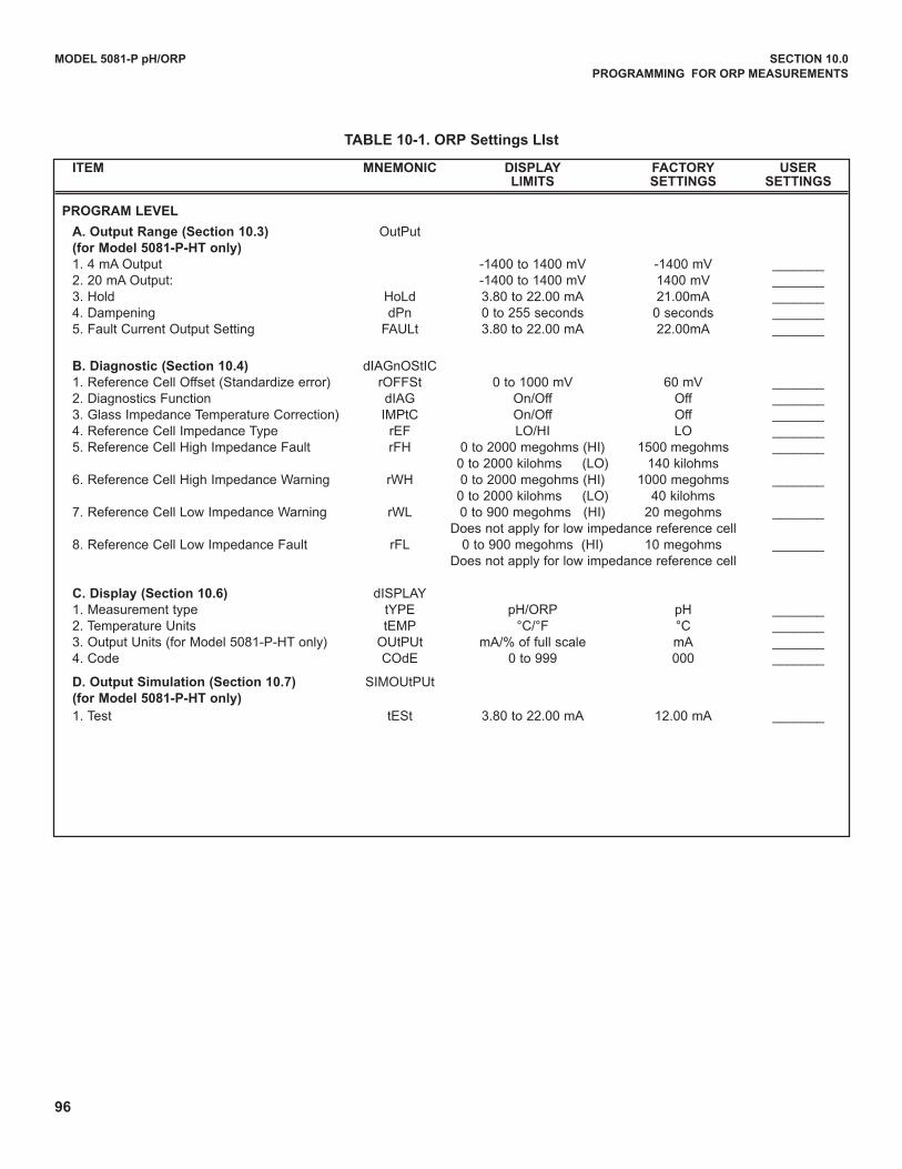
96
MODEL 5081-P pH/ORP SECTION 10.0
PROGRAMMING FOR ORP MEASUREMENTS
ITEM MNEMONIC DISPLAy FACTORy USER LIMITS SETTINGS SETTINGS
PROGRAM LEvEL
A. Output Range (Section 10.3) OutPut(for Model 5081-P-HT only)
1. 4 mA Output -1400 to 1400 mV -1400 mV _______2. 20 mA Output: -1400 to 1400 mV 1400 mV _______3. Hold HoLd 3.80 to 22.00 mA 21.00mA _______4. dampening dPn 0 to 255 seconds 0 seconds _______5. Fault Current Output Setting FAuLt 3.80 to 22.00 mA 22.00mA _______
B. Diagnostic (Section 10.4) dIAGnOStIC1. Reference Cell Offset (Standardize error) rOFFSt 0 to 1000 mV 60 mV _______2. diagnostics Function dIAG On/Off Off _______3. Glass Impedance Temperature Correction) IMPtC On/Off Off _______4. Reference Cell Impedance Type rEF LO/HI LO _______5. Reference Cell High Impedance Fault rFH 0 to 2000 megohms (HI) 1500 megohms _______
0 to 2000 kilohms (LO) 140 kilohms6. Reference Cell High Impedance Warning rWH 0 to 2000 megohms (HI) 1000 megohms _______
0 to 2000 kilohms (LO) 40 kilohms7. Reference Cell Low Impedance Warning rWL 0 to 900 megohms (HI) 20 megohms _______
does not apply for low impedance reference cell8. Reference Cell Low Impedance Fault rFL 0 to 900 megohms (HI) 10 megohms _______
does not apply for low impedance reference cell
C. Display (Section 10.6) dISPLAY1. Measurement type tYPE pH/ORP pH _______2. Temperature units tEMP °C/°F °C _______3. Output units (for Model 5081-P-HT only) OutPut mA/% of full scale mA _______4. Code COdE 0 to 999 000 _______
D. Output Simulation (Section 10.7) SIMOutPut(for Model 5081-P-HT only)
1. Test tESt 3.80 to 22.00 mA 12.00 mA _______
TABLE 10-1. ORP Settings LIst
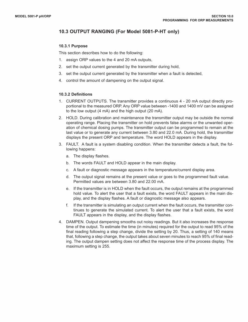
MODEL 5081-P pH/ORP SECTION 10.0
PROGRAMMING FOR ORP MEASUREMENTS
10.3 OUTPUT RANGING (For Model 5081-P-HT only)
10.3.1 Purpose
This section describes how to do the following:
1. assign ORP values to the 4 and 20 mA outputs,
2. set the output current generated by the transmitter during hold,
3. set the output current generated by the transmitter when a fault is detected,
4. control the amount of dampening on the output signal.
10.3.2 Definitions
1. CuRRENT OuTPuTS. The transmitter provides a continuous 4 - 20 mA output directly pro-portional to the measured ORP. Any ORP value between -1400 and 1400 mV can be assignedto the low output (4 mA) and the high output (20 mA).
2. HOLd. during calibration and maintenance the transmitter output may be outside the normaloperating range. Placing the transmitter on hold prevents false alarms or the unwanted oper-ation of chemical dosing pumps. The transmitter output can be programmed to remain at thelast value or to generate any current between 3.80 and 22.0 mA. during hold, the transmitterdisplays the present ORP and temperature. The word HOLd appears in the display.
3. FAuLT. A fault is a system disabling condition. When the transmitter detects a fault, the fol-lowing happens:
a. The display flashes.
b. The words FAuLT and HOLd appear in the main display.
c. A fault or diagnostic message appears in the temperature/current display area.
d. The output signal remains at the present value or goes to the programmed fault value. Permitted values are between 3.80 and 22.00 mA.
e. If the transmitter is in HOLd when the fault occurs, the output remains at the programmedhold value. To alert the user that a fault exists, the word FAuLT appears in the main dis-play, and the display flashes. A fault or diagnostic message also appears.
f. If the transmitter is simulating an output current when the fault occurs, the transmitter con-tinues to generate the simulated current. To alert the user that a fault exists, the wordFAuLT appears in the display, and the display flashes.
4. dAMPEN. Output dampening smooths out noisy readings. But it also increases the responsetime of the output. To estimate the time (in minutes) required for the output to read 95% of thefinal reading following a step change, divide the setting by 20. Thus, a setting of 140 meansthat, following a step change, the output takes about seven minutes to reach 95% of final read-ing. The output dampen setting does not affect the response time of the process display. Themaximum setting is 255.
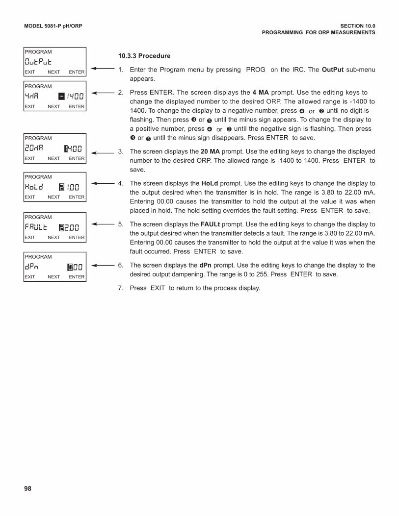
98
MODEL 5081-P pH/ORP SECTION 10.0
PROGRAMMING FOR ORP MEASUREMENTS
10.3.3 Procedure
1. Enter the Program menu by pressing PROG on the IRC. The OutPut sub-menu
appears.
2. Press ENTER. The screen displays the 4 MA prompt. use the editing keys to
change the displayed number to the desired ORP. The allowed range is -1400 to
1400. To change the display to a negative number, press è or ç until no digit is
flashing. Then press é or ê until the minus sign appears. To change the display to
a positive number, press è or ç until the negative sign is flashing. Then press
é or ê until the minus sign disappears. Press ENTER to save.
3. The screen displays the 20 MA prompt. use the editing keys to change the displayed
number to the desired ORP. The allowed range is -1400 to 1400. Press ENTER to
save.
4. The screen displays the HoLd prompt. use the editing keys to change the display to
the output desired when the transmitter is in hold. The range is 3.80 to 22.00 mA.
Entering 00.00 causes the transmitter to hold the output at the value it was when
placed in hold. The hold setting overrides the fault setting. Press ENTER to save.
5. The screen displays the FAULt prompt. use the editing keys to change the display to
the output desired when the transmitter detects a fault. The range is 3.80 to 22.00 mA.
Entering 00.00 causes the transmitter to hold the output at the value it was when the
fault occurred. Press ENTER to save.
6. The screen displays the dPn prompt. use the editing keys to change the display to the
desired output dampening. The range is 0 to 255. Press ENTER to save.
7. Press EXIT to return to the process display.
PROGRAM
HoLdEXIT NEXT ENTER
21.00
PROGRAM
FAULtEXIT NEXT ENTER
22.00
PROGRAM
dPnEXIT NEXT ENTER
PROGRAM
OutPutEXIT NEXT ENTER
PROGRAM
4MAEXIT NEXT ENTER
-1400
PROGRAM
20MAEXIT NEXT ENTER
1400
000
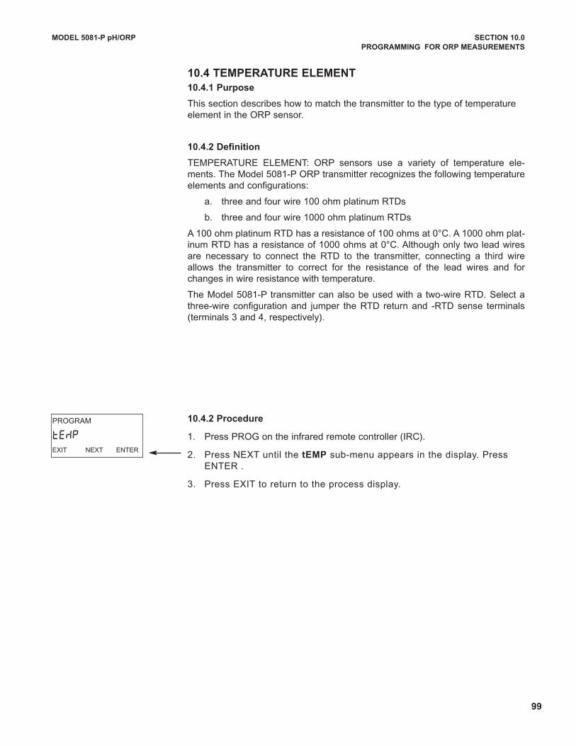
99
MODEL 5081-P pH/ORP SECTION 10.0
PROGRAMMING FOR ORP MEASUREMENTS
10.4 TEMPERATURE ELEMENT
10.4.1 Purpose
This section describes how to match the transmitter to the type of temperatureelement in the ORP sensor.
10.4.2 Definition
TEMPERATuRE ELEMENT: ORP sensors use a variety of temperature ele-ments. The Model 5081-P ORP transmitter recognizes the following temperatureelements and configurations:
a. three and four wire 100 ohm platinum RTds
b. three and four wire 1000 ohm platinum RTds
A 100 ohm platinum RTd has a resistance of 100 ohms at 0°C. A 1000 ohm plat-inum RTd has a resistance of 1000 ohms at 0°C. Although only two lead wiresare necessary to connect the RTd to the transmitter, connecting a third wireallows the transmitter to correct for the resistance of the lead wires and forchanges in wire resistance with temperature.
The Model 5081-P transmitter can also be used with a two-wire RTd. Select athree-wire configuration and jumper the RTd return and -RTd sense terminals(terminals 3 and 4, respectively).
10.4.2 Procedure
1. Press PROG on the infrared remote controller (IRC).
2. Press NEXT until the tEMP sub-menu appears in the display. PressENTER .
3. Press EXIT to return to the process display.
PROGRAM
tEMPEXIT NEXT ENTER
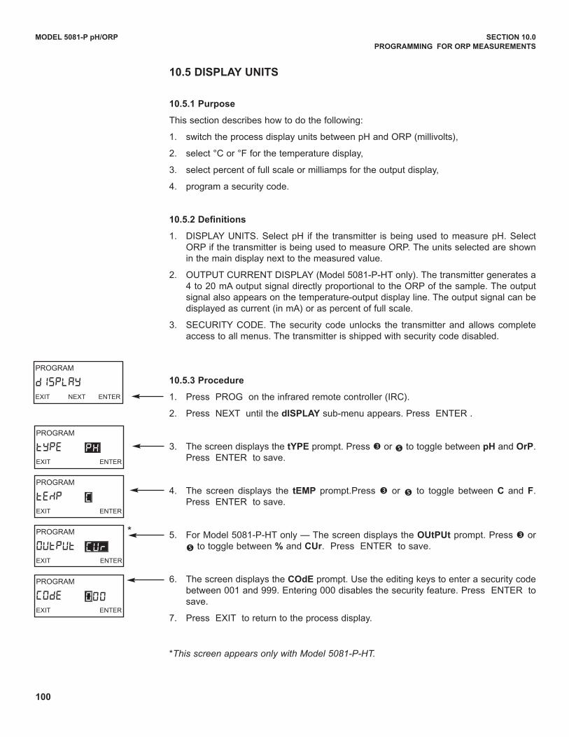
100
MODEL 5081-P pH/ORP SECTION 10.0
PROGRAMMING FOR ORP MEASUREMENTS
PROGRAM
OUtPUtEXIT ENTER
CUR
PROGRAM
CODEEXIT ENTER
000
PROGRAM
tYPEEXIT ENTER
PH
PROGRAM
tEMPEXIT ENTER
C
PROGRAM
dISPLAYEXIT NEXT ENTER
10.5 DISPLAy UNITS
10.5.1 Purpose
This section describes how to do the following:
1. switch the process display units between pH and ORP (millivolts),
2. select °C or °F for the temperature display,
3. select percent of full scale or milliamps for the output display,
4. program a security code.
10.5.2 Definitions
1. dISPLAY uNITS. Select pH if the transmitter is being used to measure pH. SelectORP if the transmitter is being used to measure ORP. The units selected are shownin the main display next to the measured value.
2. OuTPuT CuRRENT dISPLAY (Model 5081-P-HT only). The transmitter generates a4 to 20 mA output signal directly proportional to the ORP of the sample. The outputsignal also appears on the temperature-output display line. The output signal can bedisplayed as current (in mA) or as percent of full scale.
3. SECuRITY COdE. The security code unlocks the transmitter and allows completeaccess to all menus. The transmitter is shipped with security code disabled.
10.5.3 Procedure
1. Press PROG on the infrared remote controller (IRC).
2. Press NEXT until the dISPLAy sub-menu appears. Press ENTER .
3. The screen displays the tyPE prompt. Press é or ê to toggle between pH and OrP.Press ENTER to save.
4. The screen displays the tEMP prompt.Press é or ê to toggle between C and F.Press ENTER to save.
5. For Model 5081-P-HT only — The screen displays the OUtPUt prompt. Press é or
ê to toggle between % and CUr. Press ENTER to save.
6. The screen displays the COdE prompt. use the editing keys to enter a security codebetween 001 and 999. Entering 000 disables the security feature. Press ENTER tosave.
7. Press EXIT to return to the process display.
*This screen appears only with Model 5081-P-HT.
*
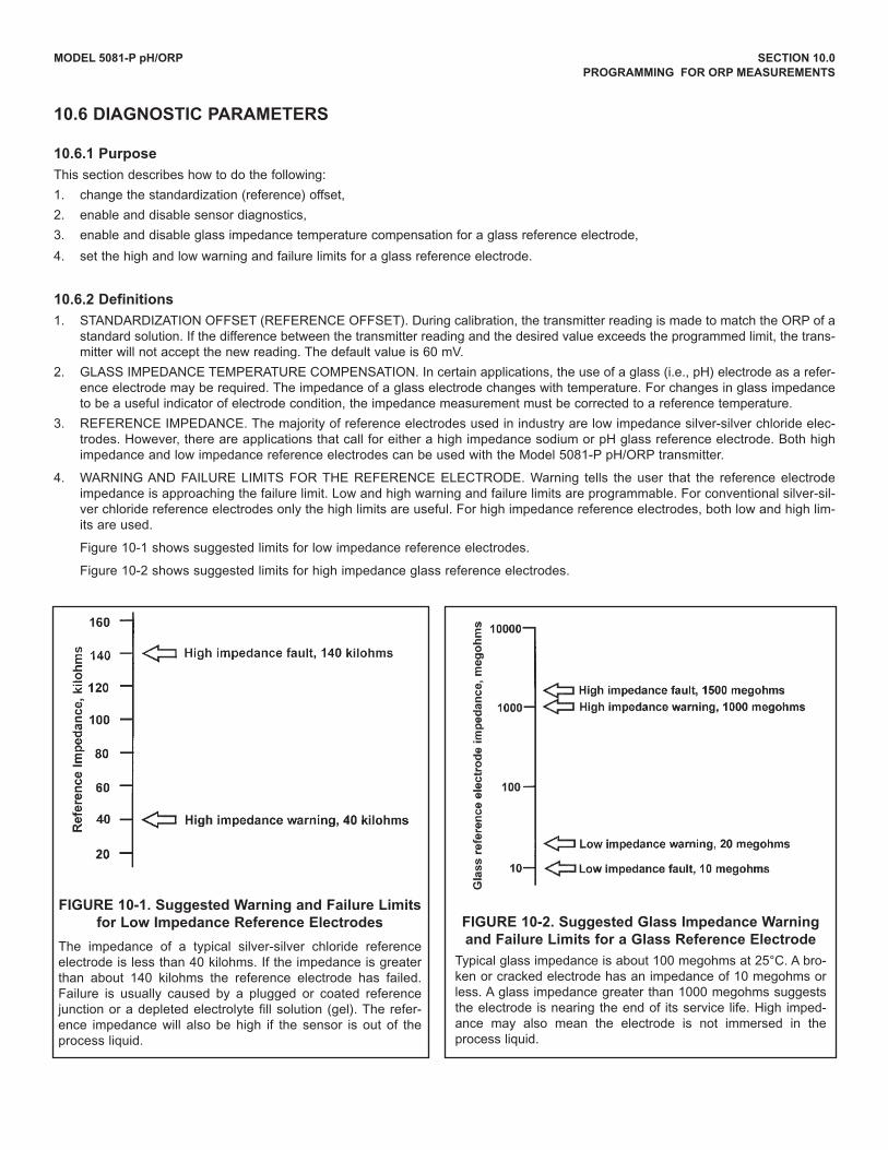
MODEL 5081-P pH/ORP SECTION 10.0
PROGRAMMING FOR ORP MEASUREMENTS
10.6 DIAGNOSTIC PARAMETERS
10.6.1 Purpose
This section describes how to do the following:
1. change the standardization (reference) offset,
2. enable and disable sensor diagnostics,
3. enable and disable glass impedance temperature compensation for a glass reference electrode,
4. set the high and low warning and failure limits for a glass reference electrode.
10.6.2 Definitions
1. STANdARdIZATION OFFSET (REFERENCE OFFSET). during calibration, the transmitter reading is made to match the ORP of astandard solution. If the difference between the transmitter reading and the desired value exceeds the programmed limit, the trans-mitter will not accept the new reading. The default value is 60 mV.
2. GLASS IMPEdANCE TEMPERATuRE COMPENSATION. In certain applications, the use of a glass (i.e., pH) electrode as a refer-ence electrode may be required. The impedance of a glass electrode changes with temperature. For changes in glass impedanceto be a useful indicator of electrode condition, the impedance measurement must be corrected to a reference temperature.
3. REFERENCE IMPEdANCE. The majority of reference electrodes used in industry are low impedance silver-silver chloride elec-trodes. However, there are applications that call for either a high impedance sodium or pH glass reference electrode. Both highimpedance and low impedance reference electrodes can be used with the Model 5081-P pH/ORP transmitter.
4. WARNING ANd FAILuRE LIMITS FOR THE REFERENCE ELECTROdE. Warning tells the user that the reference electrodeimpedance is approaching the failure limit. Low and high warning and failure limits are programmable. For conventional silver-sil-ver chloride reference electrodes only the high limits are useful. For high impedance reference electrodes, both low and high lim-its are used.
Figure 10-1 shows suggested limits for low impedance reference electrodes.
Figure 10-2 shows suggested limits for high impedance glass reference electrodes.
FIGURE 10-1. Suggested warning and Failure Limits
for Low Impedance Reference Electrodes
The impedance of a typical silver-silver chloride referenceelectrode is less than 40 kilohms. If the impedance is greaterthan about 140 kilohms the reference electrode has failed.Failure is usually caused by a plugged or coated referencejunction or a depleted electrolyte fill solution (gel). The refer-ence impedance will also be high if the sensor is out of theprocess liquid.
FIGURE 10-2. Suggested Glass Impedance warning
and Failure Limits for a Glass Reference Electrode
Typical glass impedance is about 100 megohms at 25°C. A bro-ken or cracked electrode has an impedance of 10 megohms orless. A glass impedance greater than 1000 megohms suggeststhe electrode is nearing the end of its service life. High imped-ance may also mean the electrode is not immersed in theprocess liquid.
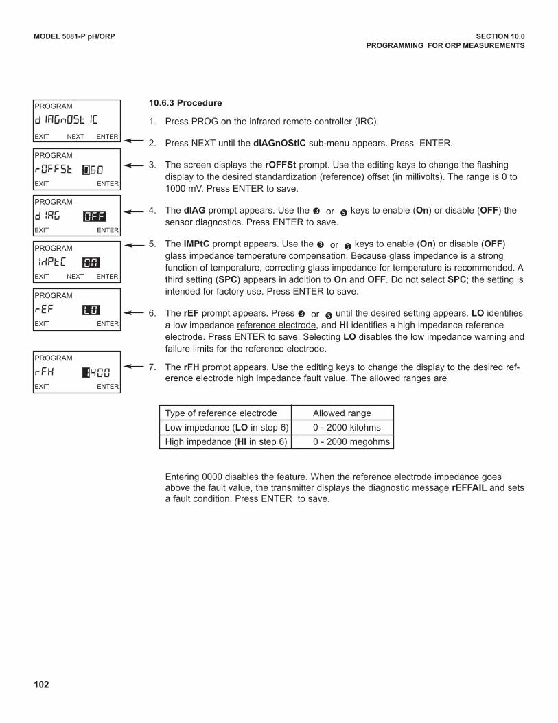
102
MODEL 5081-P pH/ORP SECTION 10.0
PROGRAMMING FOR ORP MEASUREMENTS
PROGRAM
rEFEXIT ENTER
LO
PROGRAM
IMPtCEXIT NEXT ENTER
ON
PROGRAM
rOFFStEXIT ENTER
PROGRAM
dIAGnOSTIC
EXIT NEXT ENTER
060
PROGRAM
dIAGEXIT ENTER
OFF
10.6.3 Procedure
1. Press PROG on the infrared remote controller (IRC).
2. Press NEXT until the diAGnOStIC sub-menu appears. Press ENTER.
3. The screen displays the rOFFSt prompt. use the editing keys to change the flashingdisplay to the desired standardization (reference) offset (in millivolts). The range is 0 to1000 mV. Press ENTER to save.
4. The dIAG prompt appears. use the é or ê keys to enable (On) or disable (OFF) thesensor diagnostics. Press ENTER to save.
5. The IMPtC prompt appears. use the é or ê keys to enable (On) or disable (OFF)glass impedance temperature compensation. Because glass impedance is a strongfunction of temperature, correcting glass impedance for temperature is recommended. Athird setting (SPC) appears in addition to On and OFF. do not select SPC; the setting isintended for factory use. Press ENTER to save.
6. The rEF prompt appears. Press é or ê until the desired setting appears. LO identifiesa low impedance reference electrode, and HI identifies a high impedance referenceelectrode. Press ENTER to save. Selecting LO disables the low impedance warning andfailure limits for the reference electrode.
7. The rFH prompt appears. use the editing keys to change the display to the desired ref-erence electrode high impedance fault value. The allowed ranges are
Type of reference electrode Allowed range
Low impedance (LO in step 6) 0 - 2000 kilohms
High impedance (HI in step 6) 0 - 2000 megohms
Entering 0000 disables the feature. When the reference electrode impedance goesabove the fault value, the transmitter displays the diagnostic message rEFFAIL and setsa fault condition. Press ENTER to save.
PROGRAM
rFHEXIT ENTER
1400
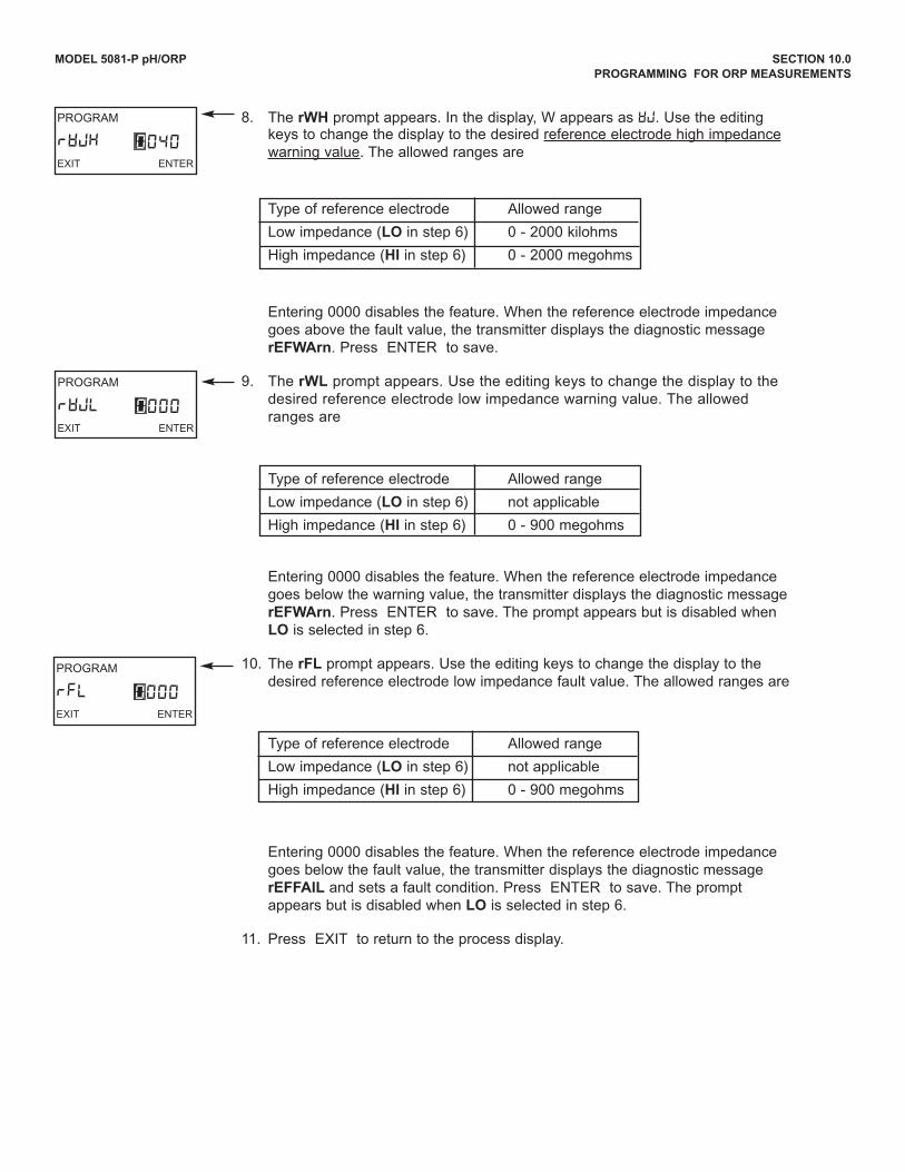
MODEL 5081-P pH/ORP SECTION 10.0
PROGRAMMING FOR ORP MEASUREMENTS
8. The rwH prompt appears. In the display, W appears as wj. use the editingkeys to change the display to the desired reference electrode high impedancewarning value. The allowed ranges are
Type of reference electrode Allowed range
Low impedance (LO in step 6) 0 - 2000 kilohms
High impedance (HI in step 6) 0 - 2000 megohms
Entering 0000 disables the feature. When the reference electrode impedancegoes above the fault value, the transmitter displays the diagnostic messagerEFwArn. Press ENTER to save.
9. The rwL prompt appears. use the editing keys to change the display to thedesired reference electrode low impedance warning value. The allowedranges are
Type of reference electrode Allowed range
Low impedance (LO in step 6) not applicable
High impedance (HI in step 6) 0 - 900 megohms
Entering 0000 disables the feature. When the reference electrode impedancegoes below the warning value, the transmitter displays the diagnostic messagerEFwArn. Press ENTER to save. The prompt appears but is disabled whenLO is selected in step 6.
10. The rFL prompt appears. use the editing keys to change the display to thedesired reference electrode low impedance fault value. The allowed ranges are
Type of reference electrode Allowed range
Low impedance (LO in step 6) not applicable
High impedance (HI in step 6) 0 - 900 megohms
Entering 0000 disables the feature. When the reference electrode impedancegoes below the fault value, the transmitter displays the diagnostic messagerEFFAIL and sets a fault condition. Press ENTER to save. The promptappears but is disabled when LO is selected in step 6.
11. Press EXIT to return to the process display.
PROGRAM
rWJLEXIT ENTER
0000
PROGRAM
rFLEXIT ENTER
0000
PROGRAM
rWJHEXIT ENTER
0040
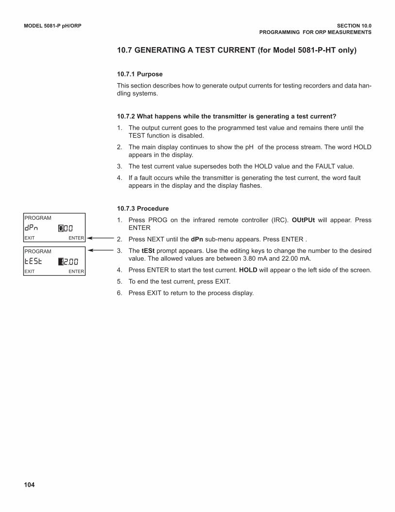
104
PROGRAM
tEStEXIT ENTER
12.00
PROGRAM
dPnEXIT ENTER
000
MODEL 5081-P pH/ORP SECTION 10.0
PROGRAMMING FOR ORP MEASUREMENTS
10.7 GENERATING A TEST CURRENT (for Model 5081-P-HT only)
10.7.1 Purpose
This section describes how to generate output currents for testing recorders and data han-dling systems.
10.7.2 what happens while the transmitter is generating a test current?
1. The output current goes to the programmed test value and remains there until the TEST function is disabled.
2. The main display continues to show the pH of the process stream. The word HOLdappears in the display.
3. The test current value supersedes both the HOLd value and the FAuLT value.
4. If a fault occurs while the transmitter is generating the test current, the word fault appears in the display and the display flashes.
10.7.3 Procedure
1. Press PROG on the infrared remote controller (IRC). OUtPUt will appear. PressENTER
2. Press NEXT until the dPn sub-menu appears. Press ENTER .
3. The tESt prompt appears. use the editing keys to change the number to the desiredvalue. The allowed values are between 3.80 mA and 22.00 mA.
4. Press ENTER to start the test current. HOLD will appear o the left side of the screen.
5. To end the test current, press EXIT.
6. Press EXIT to return to the process display.
105
MODEL 5081-P pH/ORP SECTION 11.0
MAINTENANCE
SECTION 11.0MAINTENANCE
11.1 OvERvIEw
This section gives general procedures for routine maintenance of the 5081-P pH/ORP transmitter and pH andORP sensors. The transmitter needs almost no routine maintenance. Sensors require periodic inspection andcleaning. The calibration of the transmitter-sensor combination should be checked regularly, and the loop recali-brated if necessary.
11.2 TRANSMITTER MAINTENANCE
Periodically clean the transmitter window with household ammonia or glass cleaner. The detector for the infraredremote controller is located behind the window at the top of the transmitter face. The window in front of the detec-tor must be kept clean. The o-rings and sealing surfaces must be kept clean or moisture may enter the electronicenclosure.
Most components of the transmitter are replaceable. Refer to Table 11-1 for parts and part numbers.
11.1 Overview
11.2 Transmitter Maintenance
11.3 pH Sensor Maintenance
11.4 ORP Sensor Maintenance
11.5 Calibration
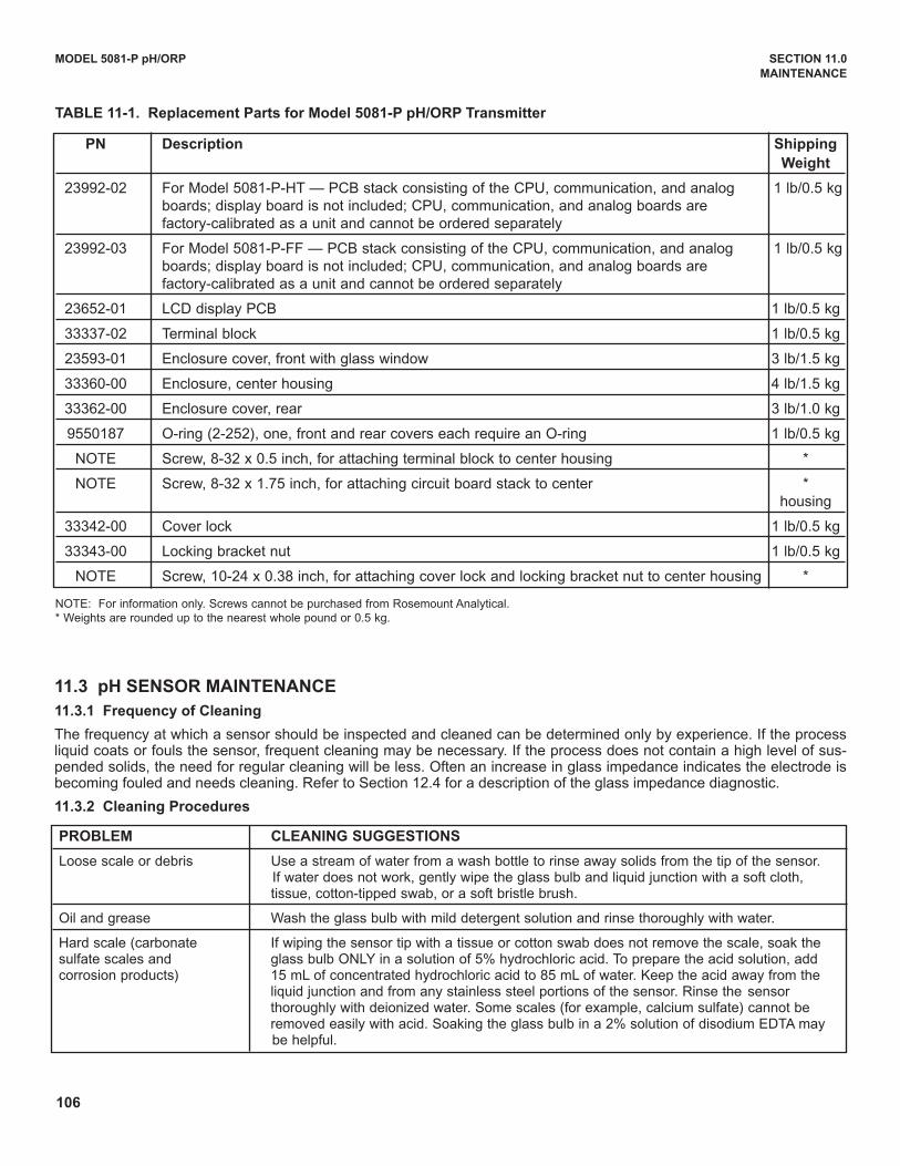
106
MODEL 5081-P pH/ORP SECTION 11.0
MAINTENANCE
TABLE 11-1. Replacement Parts for Model 5081-P pH/ORP Transmitter
PROBLEM CLEANING SUGGESTIONS
Loose scale or debris use a stream of water from a wash bottle to rinse away solids from the tip of the sensor. If water does not work, gently wipe the glass bulb and liquid junction with a soft cloth, tissue, cotton-tipped swab, or a soft bristle brush.
Oil and grease Wash the glass bulb with mild detergent solution and rinse thoroughly with water.
Hard scale (carbonate If wiping the sensor tip with a tissue or cotton swab does not remove the scale, soak thesulfate scales and glass bulb ONLY in a solution of 5% hydrochloric acid. To prepare the acid solution, addcorrosion products) 15 mL of concentrated hydrochloric acid to 85 mL of water. Keep the acid away from the
liquid junction and from any stainless steel portions of the sensor. Rinse the sensor thoroughly with deionized water. Some scales (for example, calcium sulfate) cannot be removed easily with acid. Soaking the glass bulb in a 2% solution of disodium EdTA may be helpful.
PN Description Shipping
weight
23992-02 For Model 5081-P-HT — PCB stack consisting of the CPu, communication, and analog 1 lb/0.5 kgboards; display board is not included; CPu, communication, and analog boards arefactory-calibrated as a unit and cannot be ordered separately
23992-03 For Model 5081-P-FF — PCB stack consisting of the CPu, communication, and analog 1 lb/0.5 kgboards; display board is not included; CPu, communication, and analog boards arefactory-calibrated as a unit and cannot be ordered separately
23652-01 LCd display PCB 1 lb/0.5 kg
33337-02 Terminal block 1 lb/0.5 kg
23593-01 Enclosure cover, front with glass window 3 lb/1.5 kg
33360-00 Enclosure, center housing 4 lb/1.5 kg
33362-00 Enclosure cover, rear 3 lb/1.0 kg
9550187 O-ring (2-252), one, front and rear covers each require an O-ring 1 lb/0.5 kg
NOTE Screw, 8-32 x 0.5 inch, for attaching terminal block to center housing *
NOTE Screw, 8-32 x 1.75 inch, for attaching circuit board stack to center *housing
33342-00 Cover lock 1 lb/0.5 kg
33343-00 Locking bracket nut 1 lb/0.5 kg
NOTE Screw, 10-24 x 0.38 inch, for attaching cover lock and locking bracket nut to center housing *
NOTE: For information only. Screws cannot be purchased from Rosemount Analytical.* Weights are rounded up to the nearest whole pound or 0.5 kg.
11.3 pH SENSOR MAINTENANCE
11.3.1 Frequency of Cleaning
The frequency at which a sensor should be inspected and cleaned can be determined only by experience. If the processliquid coats or fouls the sensor, frequent cleaning may be necessary. If the process does not contain a high level of sus-pended solids, the need for regular cleaning will be less. Often an increase in glass impedance indicates the electrode isbecoming fouled and needs cleaning. Refer to Section 12.4 for a description of the glass impedance diagnostic.
11.3.2 Cleaning Procedures
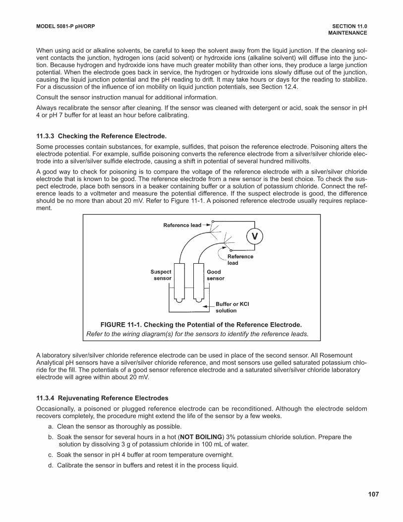
107
When using acid or alkaline solvents, be careful to keep the solvent away from the liquid junction. If the cleaning sol-vent contacts the junction, hydrogen ions (acid solvent) or hydroxide ions (alkaline solvent) will diffuse into the junc-tion. Because hydrogen and hydroxide ions have much greater mobility than other ions, they produce a large junctionpotential. When the electrode goes back in service, the hydrogen or hydroxide ions slowly diffuse out of the junction,causing the liquid junction potential and the pH reading to drift. It may take hours or days for the reading to stabilize.For a discussion of the influence of ion mobility on liquid junction potentials, see Section 12.4.
Consult the sensor instruction manual for additional information.
Always recalibrate the sensor after cleaning. If the sensor was cleaned with detergent or acid, soak the sensor in pH4 or pH 7 buffer for at least an hour before calibrating.
11.3.3 Checking the Reference Electrode.
Some processes contain substances, for example, sulfides, that poison the reference electrode. Poisoning alters theelectrode potential. For example, sulfide poisoning converts the reference electrode from a silver/silver chloride elec-trode into a silver/silver sulfide electrode, causing a shift in potential of several hundred millivolts.
A good way to check for poisoning is to compare the voltage of the reference electrode with a silver/silver chlorideelectrode that is known to be good. The reference electrode from a new sensor is the best choice. To check the sus-pect electrode, place both sensors in a beaker containing buffer or a solution of potassium chloride. Connect the ref-erence leads to a voltmeter and measure the potential difference. If the suspect electrode is good, the differenceshould be no more than about 20 mV. Refer to Figure 11-1. A poisoned reference electrode usually requires replace-ment.
A laboratory silver/silver chloride reference electrode can be used in place of the second sensor. All RosemountAnalytical pH sensors have a silver/silver chloride reference, and most sensors use gelled saturated potassium chlo-ride for the fill. The potentials of a good sensor reference electrode and a saturated silver/silver chloride laboratoryelectrode will agree within about 20 mV.
11.3.4 Rejuvenating Reference Electrodes
Occasionally, a poisoned or plugged reference electrode can be reconditioned. Although the electrode seldomrecovers completely, the procedure might extend the life of the sensor by a few weeks.
a. Clean the sensor as thoroughly as possible.
b. Soak the sensor for several hours in a hot (NOT BOILING) 3% potassium chloride solution. Prepare the solution by dissolving 3 g of potassium chloride in 100 mL of water.
c. Soak the sensor in pH 4 buffer at room temperature overnight.
d. Calibrate the sensor in buffers and retest it in the process liquid.
MODEL 5081-P pH/ORP SECTION 11.0
MAINTENANCE
FIGURE 11-1. Checking the Potential of the Reference Electrode.
Refer to the wiring diagram(s) for the sensors to identify the reference leads.
108
11.4 ORP SENSOR MAINTENANCE
11.4.1 Frequency of Cleaning
The frequency at which an ORP sensor should be inspected and cleaned can be determined only by experience. If theprocess liquid coats or fouls the sensor, frequent cleaning may be necessary. If the process does not contain a high levelof suspended solids, the need for regular cleaning will be less.
11.4.2 Cleaning Procedures
The platinum electrode is easily cleaned by using a tissue to rub the metal surface with a paste of baking soda (sodiumbicarbonate). A clean platinum electrode is bright and shiny.
11.4.3 Checking the Reference Electrode
ORP electrodes manufactured by Rosemount Analytical have a silver/silver chloride reference. Section 11.3.3 describeshow to check the performance of the reference electrode.
11.5 CALIBRATION
11.5.1 General
Many users regard calibration as a routine part of sensor/transmitter maintenance. Procedures for calibrating pH sensors,ORP sensors, and general information regarding the use of pH calibration buffers and ORP standards are given inSections 7.0 Calibration of pH Measurements, 9.0 Calibration of ORP Measurements, 13.0 pH Measurements, and 13.0ORP Measurements.
11.5.2 Calibration Frequency
The frequency at which sensors should be calibrated can be determined only by experience. Many factors influence cali-bration frequency. Sensors installed in dirty or corrosive process streams usually require more frequent calibration thansensors used in clean water. Sensors measuring extreme pH values, particularly high pH, also require more frequent cali-bration than sensors measuring mid-range pH. The width of the pH or ORP control range and the consequences of anout-of-limits condition has a major influence on calibration frequency. The narrower the control range and the greater thesensitivity of the process to control excursions, the more often the sensor should be checked. Finally, if monitoring dataare reported to regulatory agencies, the agency itself may dictate the calibration frequency.
use the following procedure to determine how often a pH sensor should be calibrated.
1. Calibrate the sensor. Record the date of calibration and the sensor response in buffers. That is, after calibrating,place the sensor back in the buffers and record the pH and temperature reading in each buffer. Also note the value ofthe reference offset and slope.
2. Install the sensor in the process stream.
3. After the appropriate period—two weeks for a clean process, several days for a dirty or aggressive process—removethe sensor and check its performance in buffers. Record the pH and temperature readings. The performance of thesensor in buffer after it has been in service is called the as-found condition. Keeping a good record of as-found datais an important step in determining the calibration frequency.
4. If the as-found data are acceptable, do not recalibrate the sensor. Return it to the process. Continue checking the cal-ibration at the same interval.
5. If the as-found data are not acceptable, recalibrate the sensor. After calibration, check the sensor response in eachbuffer and record the results. Also note the reference offset and the slope. Return the sensor to service. Check thesensor again after a period shorter than the one originally selected. For example, if the first interval was two weeks,repeat the check after one week.
6. After a while it will become apparent how long the sensor holds calibration. The minimum calibration frequency canthen be determined.
7. Check the calibration of the sensor at least several times during the regular calibration interval. Interim checks verifythe sensor is still in calibration and validate the process measurements made since the last calibration or calibrationcheck.
MODEL 5081-P pH/ORP SECTION 11.0
MAINTENANCE
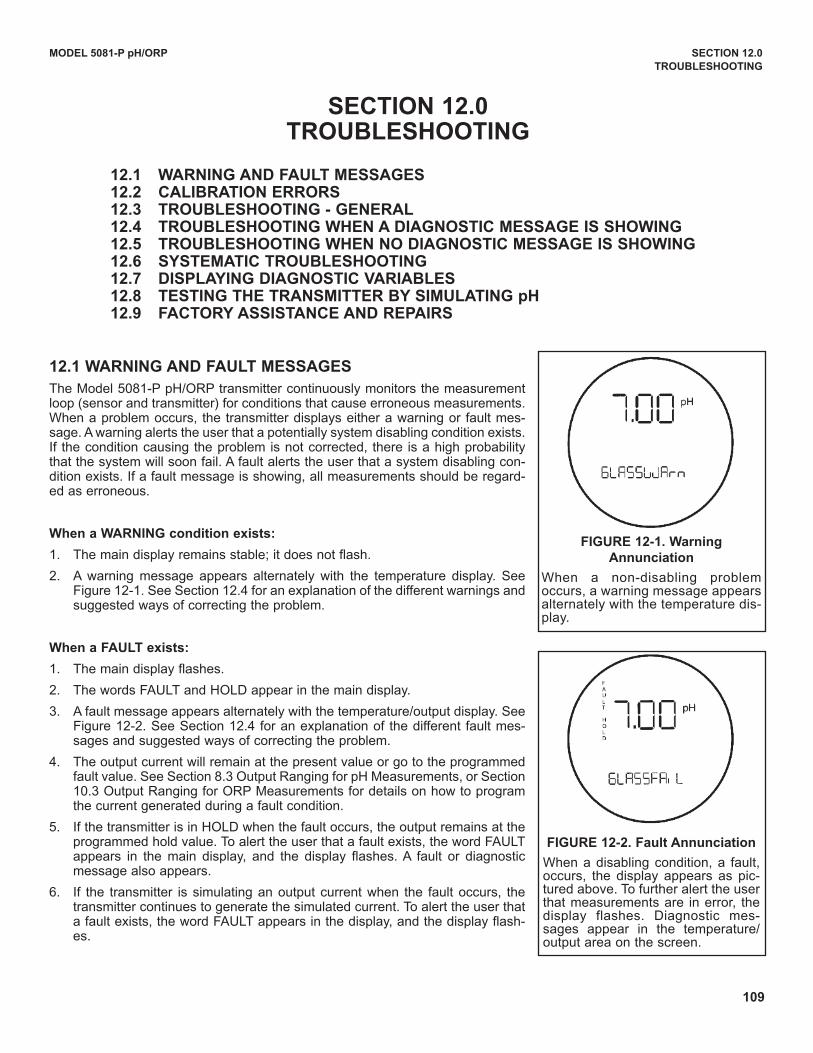
109
MODEL 5081-P pH/ORP SECTION 12.0
TROUBLESHOOTING
SECTION 12.0TROUBLESHOOTING
12.1 wARNING AND FAULT MESSAGES12.2 CALIBRATION ERRORS 12.3 TROUBLESHOOTING - GENERAL12.4 TROUBLESHOOTING wHEN A DIAGNOSTIC MESSAGE IS SHOwING12.5 TROUBLESHOOTING wHEN NO DIAGNOSTIC MESSAGE IS SHOwING12.6 SySTEMATIC TROUBLESHOOTING12.7 DISPLAyING DIAGNOSTIC vARIABLES12.8 TESTING THE TRANSMITTER By SIMULATING pH12.9 FACTORy ASSISTANCE AND REPAIRS
12.1 wARNING AND FAULT MESSAGES
The Model 5081-P pH/ORP transmitter continuously monitors the measurementloop (sensor and transmitter) for conditions that cause erroneous measurements.When a problem occurs, the transmitter displays either a warning or fault mes-sage. A warning alerts the user that a potentially system disabling condition exists.If the condition causing the problem is not corrected, there is a high probabilitythat the system will soon fail. A fault alerts the user that a system disabling con-dition exists. If a fault message is showing, all measurements should be regard-ed as erroneous.
when a wARNING condition exists:
1. The main display remains stable; it does not flash.
2. A warning message appears alternately with the temperature display. SeeFigure 12-1. See Section 12.4 for an explanation of the different warnings andsuggested ways of correcting the problem.
when a FAULT exists:
1. The main display flashes.
2. The words FAuLT and HOLd appear in the main display.
3. A fault message appears alternately with the temperature/output display. SeeFigure 12-2. See Section 12.4 for an explanation of the different fault mes-sages and suggested ways of correcting the problem.
4. The output current will remain at the present value or go to the programmedfault value. See Section 8.3 Output Ranging for pH Measurements, or Section10.3 Output Ranging for ORP Measurements for details on how to programthe current generated during a fault condition.
5. If the transmitter is in HOLd when the fault occurs, the output remains at theprogrammed hold value. To alert the user that a fault exists, the word FAuLTappears in the main display, and the display flashes. A fault or diagnosticmessage also appears.
6. If the transmitter is simulating an output current when the fault occurs, thetransmitter continues to generate the simulated current. To alert the user thata fault exists, the word FAuLT appears in the display, and the display flash-es.
FIGURE 12-1. warning
Annunciation
When a non-disabling problemoccurs, a warning message appearsalternately with the temperature dis-play.
FIGURE 12-2. Fault Annunciation
When a disabling condition, a fault,occurs, the display appears as pic-tured above. To further alert the userthat measurements are in error, thedisplay flashes. diagnostic mes-sages appear in the temperature/output area on the screen.
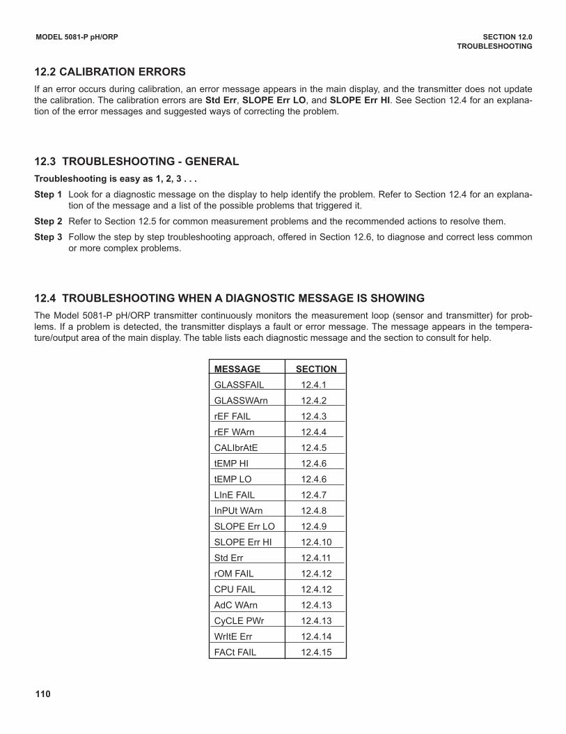
110
MODEL 5081-P pH/ORP SECTION 12.0
TROUBLESHOOTING
12.2 CALIBRATION ERRORS
If an error occurs during calibration, an error message appears in the main display, and the transmitter does not updatethe calibration. The calibration errors are Std Err, SLOPE Err LO, and SLOPE Err HI. See Section 12.4 for an explana-tion of the error messages and suggested ways of correcting the problem.
12.3 TROUBLESHOOTING - GENERAL
Troubleshooting is easy as 1, 2, 3 . . .
Step 1 Look for a diagnostic message on the display to help identify the problem. Refer to Section 12.4 for an explana-tion of the message and a list of the possible problems that triggered it.
Step 2 Refer to Section 12.5 for common measurement problems and the recommended actions to resolve them.
Step 3 Follow the step by step troubleshooting approach, offered in Section 12.6, to diagnose and correct less commonor more complex problems.
12.4 TROUBLESHOOTING wHEN A DIAGNOSTIC MESSAGE IS SHOwING
The Model 5081-P pH/ORP transmitter continuously monitors the measurement loop (sensor and transmitter) for prob-lems. If a problem is detected, the transmitter displays a fault or error message. The message appears in the tempera-ture/output area of the main display. The table lists each diagnostic message and the section to consult for help.
MESSAGE SECTION
GLASSFAIL 12.4.1
GLASSWArn 12.4.2
rEF FAIL 12.4.3
rEF WArn 12.4.4
CALIbrAtE 12.4.5
tEMP HI 12.4.6
tEMP LO 12.4.6
LInE FAIL 12.4.7
InPut WArn 12.4.8
SLOPE Err LO 12.4.9
SLOPE Err HI 12.4.10
Std Err 12.4.11
rOM FAIL 12.4.12
CPu FAIL 12.4.12
AdC WArn 12.4.13
CyCLE PWr 12.4.13
WrItE Err 12.4.14
FACt FAIL 12.4.15
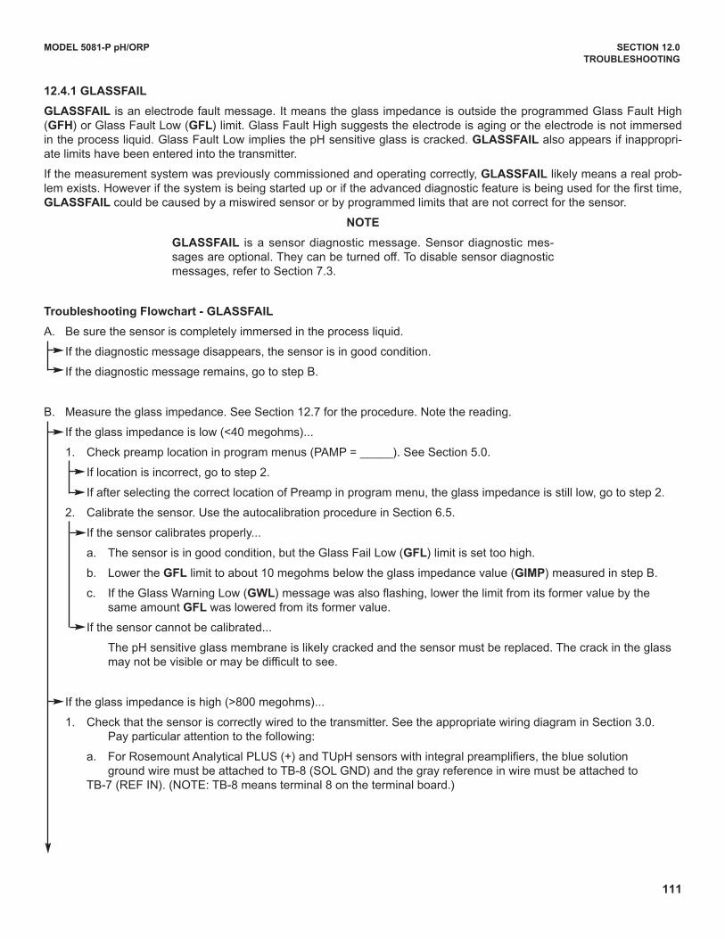
111
MODEL 5081-P pH/ORP SECTION 12.0
TROUBLESHOOTING
12.4.1 GLASSFAIL
GLASSFAIL is an electrode fault message. It means the glass impedance is outside the programmed Glass Fault High(GFH) or Glass Fault Low (GFL) limit. Glass Fault High suggests the electrode is aging or the electrode is not immersedin the process liquid. Glass Fault Low implies the pH sensitive glass is cracked. GLASSFAIL also appears if inappropri-ate limits have been entered into the transmitter.
If the measurement system was previously commissioned and operating correctly, GLASSFAIL likely means a real prob-lem exists. However if the system is being started up or if the advanced diagnostic feature is being used for the first time,GLASSFAIL could be caused by a miswired sensor or by programmed limits that are not correct for the sensor.
NOTE
GLASSFAIL is a sensor diagnostic message. Sensor diagnostic mes-sages are optional. They can be turned off. To disable sensor diagnosticmessages, refer to Section 7.3.
Troubleshooting Flowchart - GLASSFAIL
A. Be sure the sensor is completely immersed in the process liquid.
If the diagnostic message disappears, the sensor is in good condition.
If the diagnostic message remains, go to step B.
B. Measure the glass impedance. See Section 12.7 for the procedure. Note the reading.
If the glass impedance is low (<40 megohms)...
1. Check preamp location in program menus (PAMP = _____). See Section 5.0.
If location is incorrect, go to step 2.
If after selecting the correct location of Preamp in program menu, the glass impedance is still low, go to step 2.
2. Calibrate the sensor. use the autocalibration procedure in Section 6.5.
If the sensor calibrates properly...
a. The sensor is in good condition, but the Glass Fail Low (GFL) limit is set too high.
b. Lower the GFL limit to about 10 megohms below the glass impedance value (GIMP) measured in step B.
c. If the Glass Warning Low (GwL) message was also flashing, lower the limit from its former value by the same amount GFL was lowered from its former value.
If the sensor cannot be calibrated...
The pH sensitive glass membrane is likely cracked and the sensor must be replaced. The crack in the glass may not be visible or may be difficult to see.
If the glass impedance is high (>800 megohms)...
1. Check that the sensor is correctly wired to the transmitter. See the appropriate wiring diagram in Section 3.0. Pay particular attention to the following:
a. For Rosemount Analytical PLuS (+) and TupH sensors with integral preamplifiers, the blue solution ground wire must be attached to TB-8 (SOL GNd) and the gray reference in wire must be attached to
TB-7 (REF IN). (NOTE: TB-8 means terminal 8 on the terminal board.)
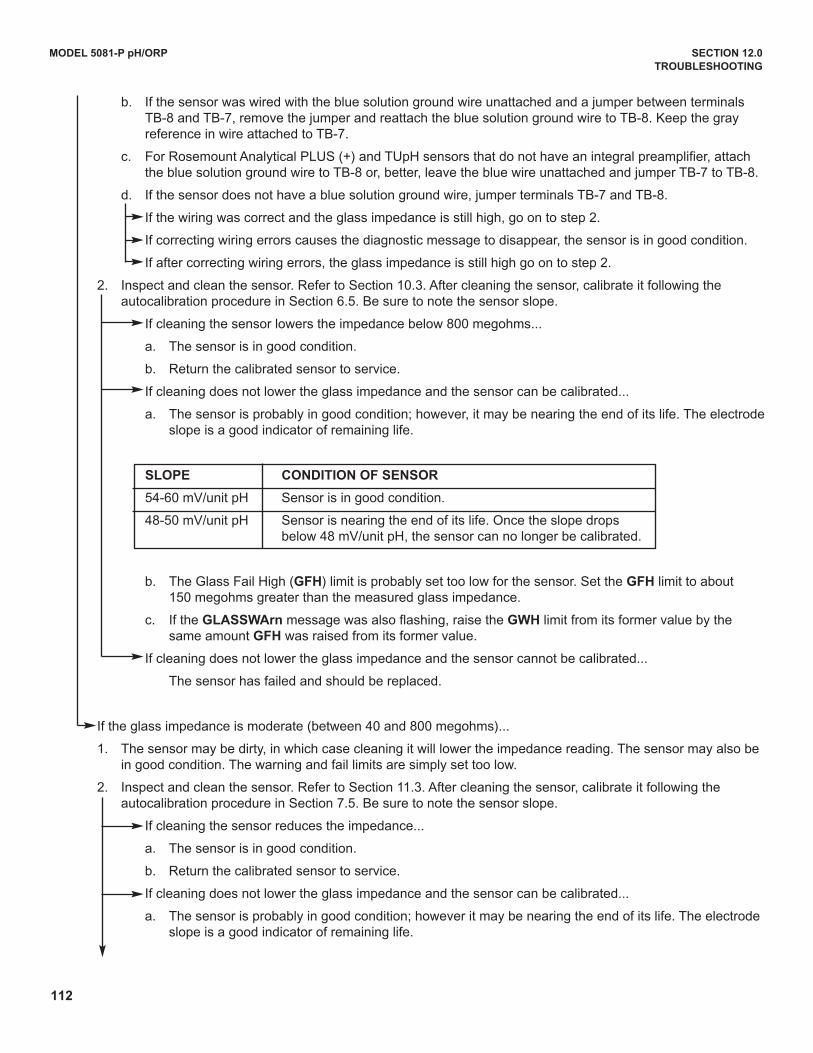
112
MODEL 5081-P pH/ORP SECTION 12.0
TROUBLESHOOTING
b. If the sensor was wired with the blue solution ground wire unattached and a jumper between terminals TB-8 and TB-7, remove the jumper and reattach the blue solution ground wire to TB-8. Keep the gray reference in wire attached to TB-7.
c. For Rosemount Analytical PLuS (+) and TupH sensors that do not have an integral preamplifier, attach the blue solution ground wire to TB-8 or, better, leave the blue wire unattached and jumper TB-7 to TB-8.
d. If the sensor does not have a blue solution ground wire, jumper terminals TB-7 and TB-8.
If the wiring was correct and the glass impedance is still high, go on to step 2.
If correcting wiring errors causes the diagnostic message to disappear, the sensor is in good condition.
If after correcting wiring errors, the glass impedance is still high go on to step 2.
2. Inspect and clean the sensor. Refer to Section 10.3. After cleaning the sensor, calibrate it following the autocalibration procedure in Section 6.5. Be sure to note the sensor slope.
If cleaning the sensor lowers the impedance below 800 megohms...
a. The sensor is in good condition.
b. Return the calibrated sensor to service.
If cleaning does not lower the glass impedance and the sensor can be calibrated...
a. The sensor is probably in good condition; however, it may be nearing the end of its life. The electrodeslope is a good indicator of remaining life.
SLOPE CONDITION OF SENSOR
54-60 mV/unit pH Sensor is in good condition.
48-50 mV/unit pH Sensor is nearing the end of its life. Once the slope drops below 48 mV/unit pH, the sensor can no longer be calibrated.
b. The Glass Fail High (GFH) limit is probably set too low for the sensor. Set the GFH limit to about 150 megohms greater than the measured glass impedance.
c. If the GLASSwArn message was also flashing, raise the GwH limit from its former value by the same amount GFH was raised from its former value.
If cleaning does not lower the glass impedance and the sensor cannot be calibrated...
The sensor has failed and should be replaced.
If the glass impedance is moderate (between 40 and 800 megohms)...
1. The sensor may be dirty, in which case cleaning it will lower the impedance reading. The sensor may also be in good condition. The warning and fail limits are simply set too low.
2. Inspect and clean the sensor. Refer to Section 11.3. After cleaning the sensor, calibrate it following the autocalibration procedure in Section 7.5. Be sure to note the sensor slope.
If cleaning the sensor reduces the impedance...
a. The sensor is in good condition.
b. Return the calibrated sensor to service.
If cleaning does not lower the glass impedance and the sensor can be calibrated...
a. The sensor is probably in good condition; however it may be nearing the end of its life. The electrode slope is a good indicator of remaining life.
113
MODEL 5081-P pH/ORP SECTION 12.0
TROUBLESHOOTING
SLOPE STATUS OF SENSOR
54-60 mV/unit pH Sensor is in good condition.
48-50 mV/unit pH Sensor is nearing the end of its life. Once the slope drops below 48 mV/unit pH, the sensor can no longer be calibrated.
b. The Glass Fail High (GFH) limit is probably set too low for the sensor. Set the GFH limit to about 150 megohms greater than the measured glass impedance.
c. If the GLASSwArn message was also flashing, raise the GwH limit from its former value by the same amount GFH was raised from its former value.
If cleaning does not lower the glass impedance and the sensor cannot be calibrated...
The sensor has failed and should be replaced.
12.4.2 GLASSwArn
GLASSwArn is an electrode fault message. It means the glass impedance is outside the programmed Glass WarningHigh (GwH) or Glass Warning Low (GwL) limit. Ideally, when the measurement system exceeds the glass warning limits,the user will have adequate time to diagnose and correct problems before a failure occurs. High impedance implies theelectrode is aging or the sensor is not completely submerged in the process liquid. Low impedance suggests the pH sen-sitive glass is cracked. The message also appears if inappropriate limits have been entered into the transmitter.
If the measurement system was previously commissioned and operating correctly, GLASSwArn likely means a real prob-lem exists. However, if the system is being started up or if the advanced diagnostic feature is being used for the first time,GLASSwArn could be caused by a miswired sensor or by programmed limits that are not correct for the sensor.
NOTE
GLASSwArn is a sensor diagnostic message. All sensor diagnosticmessages are optional. They can be turned off. To disable sensor diag-nostic messages, refer to Section 8.4.
Troubleshooting Flowchart - GLASSwArn
Troubleshooting GLASSwArn problems is exactly the same steps as troubleshooting GLASSFAIL problems. Refer toSection 12.4.1.
12.4.3 rEF FAIL
rEF FAIL is an electrode fault message. rEF FAIL means that the reference impedance exceeds the programmedReference Fault High (RFH) limit. A plugged or dry reference junction is the usual cause of a high reference impedance.High reference impedance also occurs if the sensor is not submerged in the process liquid or if inappropriate limits havebeen entered into the transmitter.
If the measurement system was previously commissioned and operating correctly, rEF FAIL likely means a real problemexists. However, if the system is being started up or if the advanced diagnostic feature is being used for the first time,rEFFAIL could be caused by a miswired sensor or by programmed limits that are not correct for the sensor.
NOTE
rEF FAIL is a sensor diagnostic message. All sensor diagnostic mes-sages are optional. They can be turned off. To disable sensor diagnosticmessages, refer to Section 8.4.
114
MODEL 5081-P pH/ORP SECTION 12.0
TROUBLESHOOTING
Troubleshooting Flowchart - rEF FAIL
A. Be sure the sensor is completely immersed in the process liquid.
If the diagnostic message disappears, the sensor is in good condition.
If the diagnostic message remains, go to step B.
B. Check that the sensor is properly wired to the transmitter. See the appropriate wiring diagram in Section 3.0. Be sure the reference in wire is attached to TB-7 and the solution ground wire is attached to TB-8. (NOTE: TB-8 means
terminal 8 on the terminal board.)
If correcting wiring problems makes the diagnostic message disappear, the sensor is in good condition.
If wiring is correct and the message still remains, go to step C.
C. Measure and make a note of the reference impedance (rIMP). See Section 12.7.
If the reference impedance is low (<70 kilohms)...
a. The reference electrode is in good condition. pH sensors manufactured by Rosemount Analytical use low impedance silver/silver chloride reference electrodes.
b. The reference failure high (RFH) limit is probably set too low. Change the limit to a value about 50 kilohms greater than the measured reference impedance. If rEF wARN was also displayed, change the reference warning high (RwH) limit to about 25 kilohms above the measured reference impedance.
If the reference impedance is high (>70 kilohms)...
1. The sensor may be dirty, in which case cleaning it will lower the impedance. If the sensor is rebuildable, the reference electrolyte may be depleted. Finally, the sensor may be in good condition. The warning andfailure limits are simply set too high.
2. Inspect and clean the sensor. Refer to Section 11.3. If the sensor is rebuildable, replace the reference junction and replenish the electrolyte solution. Refer to the sensor instruction manual for details. Check the reference impedance again.
If cleaning the sensor reduces the impedance...
a. The sensor is in good condition. Calibrate the sensor and return it to the process.
b. Change the reference failure high (RFH) limit to a value about 50 kilohms greater than the measured reference impedance. If rEF wARN was also displayed, change the reference warninghigh (RwH) limit to about 25 kilohms above the measured reference impedance.
If cleaning does not reduce the impedance and the sensor is not rebuildable...
a. Try the reference junction rejuvenation procedure described in Section 11.3.4.
b. The rejuvenation procedure may not work. At best it will get a little more life out of a sensor with a plugged reference.
c. Whether or not the rejuvenation procedure worked, go on to step 3.
3. Recalibrate the sensor using the autocalibration procedure in Section 6.5.
If the sensor can be calibrated...
a. The sensor is in good condition. Return it to the process.
b. Change the reference failure high (RFH) limit to a value about 50 kilohms greater than the measured reference impedance. If rEF wARN was also displayed, change the reference warninghigh (RwH) limit to about 25 kilohms greater than the measured reference impedance.
If the sensor cannot be calibrated...
The sensor has failed and must be replaced.
115
MODEL 5081-P pH/ORP SECTION 12.0
TROUBLESHOOTING
12.4.4 rEFwArn
rEF wArn is an electrode fault message. It means the reference electrode impedance exceeds the programmedReference Warning High (RwH) limit. Ideally, when the measurement system exceeds the warning limits, the user willhave adequate time to diagnose and correct problems before a failure occurs. A high reference impedance implies thatthe liquid junction is plugged or the reference electrolyte is depleted. The message also appears if an inappropriate limithas been entered into the transmitter.
If the measurement system was previously commissioned and operating correctly, rEF wArn likely means a real problemexists. However, if the system is being started up or if the advanced diagnostic feature is being used for the first time, rEF
wArn could be caused by a miswired sensor or by programmed limits that are not correct for the sensor.
NOTE
rEF wArn is a sensor diagnostic message. Sensor diagnostic messagesare optional. They can be turned off. To disable sensor diagnostic mes-sages, refer to Section 8.4.
Troubleshooting Flowchart - rEF wArn
Troubleshooting rEF wArn problems is exactly the same as troubleshooting rEF FAIL problems. Refer to Section 12.4.3.
12.4.5 CALIbrAtE
CALIbrAtE is a diagnostic intended for future use. If the CALIbrAtE message is showing go to Section 8.3 and disableCALIbrAte.
12.4.6 tEMP HI and tEMP LO
tEMP HI and tEMP LO mean the transmitter has detected a problem with the temperature measuring circuit. The problemmay lie in the sensor, the cable, or the transmitter. The determination of temperature is an integral part of the pH meas-urement. Therefore, failure of the temperature measuring circuit is a system disabling condition. However, in an emer-gency, automatic temperature compensation can be disabled and the transmitter placed in manual temperaturecompensation. Refer to Section 8.5. For manual temperature compensation, choose a temperature equal to the averagetemperature of the process. The resulting pH reading will be in error. The more variable the temperature and the furtherthe pH from 7, the greater the error.
Troubleshooting Flowchart- tEMP HI and tEMP LO
A. Check wiring, jumper settings, and software settings.
1. Check the wiring between the sensor and the transmitter. Refer to the appropriate wiring diagram in Section 3.0. Pay particular attention to TB-3 (RTd RTN), TB-4 (RTd SN), and TB-5 (RTd RTN). (NOTE: TB-3 means terminal 3 on the terminal board.)
2. Be sure the software settings in Section 8.5 match the type of RTd in the sensor.
If the diagnostic message disappears, the sensor is in good condition.
If the message persists, go to step B.
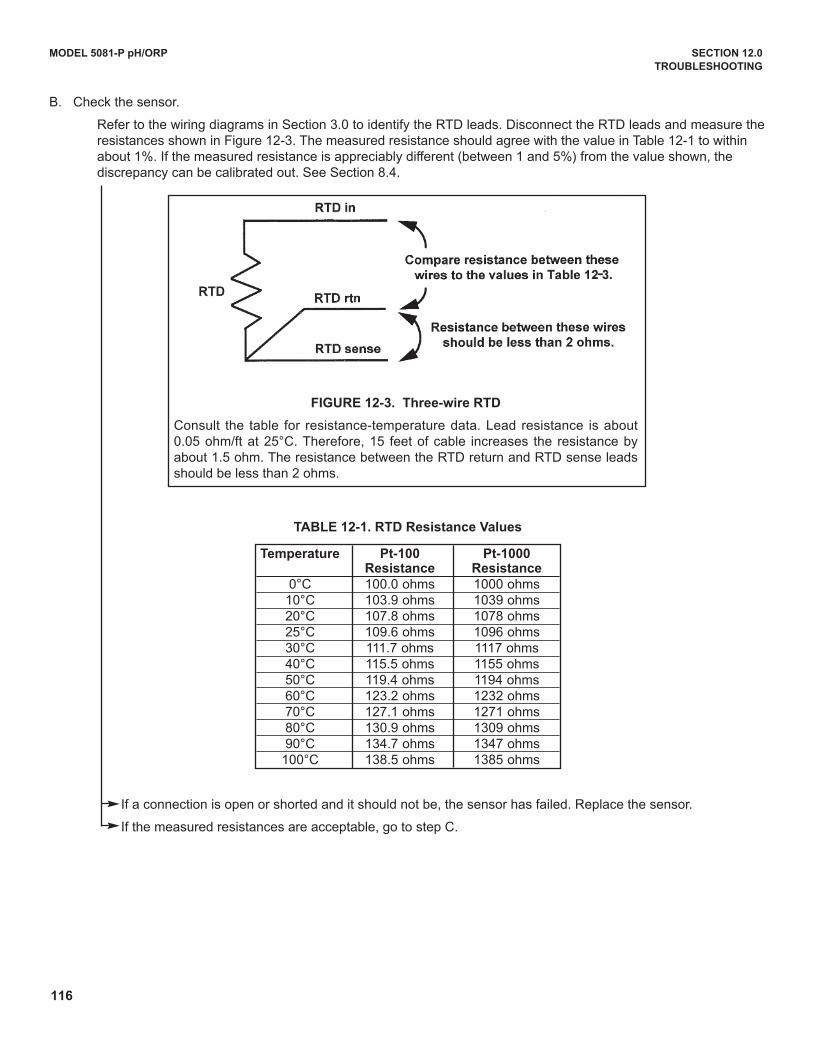
116
MODEL 5081-P pH/ORP SECTION 12.0
TROUBLESHOOTING
B. Check the sensor.
Refer to the wiring diagrams in Section 3.0 to identify the RTd leads. disconnect the RTd leads and measure theresistances shown in Figure 12-3. The measured resistance should agree with the value in Table 12-1 to within about 1%. If the measured resistance is appreciably different (between 1 and 5%) from the value shown, the discrepancy can be calibrated out. See Section 8.4.
If a connection is open or shorted and it should not be, the sensor has failed. Replace the sensor.
If the measured resistances are acceptable, go to step C.
FIGURE 12-3. Three-wire RTD
Consult the table for resistance-temperature data. Lead resistance is about0.05 ohm/ft at 25°C. Therefore, 15 feet of cable increases the resistance byabout 1.5 ohm. The resistance between the RTd return and RTd sense leadsshould be less than 2 ohms.
Temperature Pt-100 Pt-1000Resistance Resistance
0°C 100.0 ohms 1000 ohms10°C 103.9 ohms 1039 ohms20°C 107.8 ohms 1078 ohms25°C 109.6 ohms 1096 ohms30°C 111.7 ohms 1117 ohms40°C 115.5 ohms 1155 ohms50°C 119.4 ohms 1194 ohms60°C 123.2 ohms 1232 ohms70°C 127.1 ohms 1271 ohms80°C 130.9 ohms 1309 ohms90°C 134.7 ohms 1347 ohms
100°C 138.5 ohms 1385 ohms
TABLE 12-1. RTD Resistance values
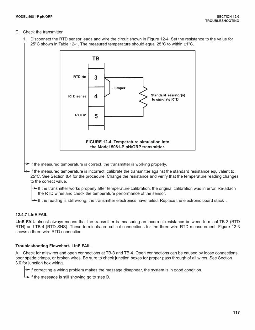
117
MODEL 5081-P pH/ORP SECTION 12.0
TROUBLESHOOTING
C. Check the transmitter.
1. disconnect the RTd sensor leads and wire the circuit shown in Figure 12-4. Set the resistance to the value for 25°C shown in Table 12-1. The measured temperature should equal 25°C to within ±1°C.
If the measured temperature is correct, the transmitter is working properly.
If the measured temperature is incorrect, calibrate the transmitter against the standard resistance equivalent to 25°C. See Section 8.4 for the procedure. Change the resistance and verify that the temperature reading changes to the correct value.
If the transmitter works properly after temperature calibration, the original calibration was in error. Re-attach the RTd wires and check the temperature performance of the sensor.
If the reading is still wrong, the transmitter electronics have failed. Replace the electronic board stack .
12.4.7 LInE FAIL
LInE FAIL almost always means that the transmitter is measuring an incorrect resistance between terminal TB-3 (RTdRTN) and TB-4 (RTd SNS). These terminals are critical connections for the three-wire RTd measurement. Figure 12-3shows a three-wire RTd connection.
Troubleshooting Flowchart- LInE FAIL
A. Check for miswires and open connections at TB-3 and TB-4. Open connections can be caused by loose connections, poor spade crimps, or broken wires. Be sure to check junction boxes for proper pass through of all wires. See Section 3.0 for junction box wiring.
If correcting a wiring problem makes the message disappear, the system is in good condition.
If the message is still showing go to step B.
FIGURE 12-4. Temperature simulation into
the Model 5081-P pH/ORP transmitter.
118
MODEL 5081-P pH/ORP SECTION 12.0
TROUBLESHOOTING
B. The RTd sense or the RTd return wire inside the sensor cable may be broken. Keep the sensor wires attached and jumper TB-3 and TB-4.
If the diagnostic message disappears, either the RTd return or RTd sense wire is broken. To verify a broken wire,disconnect the leads and measure the resistance between them. Installing the jumper completes the circuit, but bypasses the three-wire function. The transmitter no longer corrects for changes in lead wire resistance withtemperature. Replace the sensor as soon as possible.
If the diagnostic message remains, go to step C.
C. The cable connecting the sensor to the transmitter may be too long. Test using a sensor with a shorter cable.
If shortening the cable eliminates the problem, move the transmitter closer to the sensor. It may also be possible to increase diameter of the RTd wires. Consult the factory for assistance.
If the diagnostic message remains go to step d.
d. Check the performance of the transmitter. Simulate both temperature and pH. See Section 12.4.6 (steps B and C) for temperature simulation and Section 12.8 for pH simulation.
If the transmitter fails either simulation, the electronic board stack should be replaced.
If the transmitter passes the simulations, the transmitter is in good condition and the sensor should be replaced.
12.4.8 InPUt wArn
InPUt wArn means that the input value or the calculated pH is outside the measurement range. The measured pH is lessthan -2 or greater than 16.
Troubleshooting Flowchart-InPUt wArn
A. Check for miswires and open connections, particularly at TB-10. Open connections can be caused by loose connections, poor spade crimps, or broken wires. Be sure to check junction boxes for proper pass through of all wires. See Section 3.0 for junction box wiring.
If correcting a wiring problem clears the message, the system is in good condition.
If the message is still showing go to step B.
B. Check that the transmitter is working properly by simulating a pH input. See Section 12.8.
If the transmitter does not respond to simulated inputs, replace the board stack.
If the transmitter performs satisfactorily and the preamplifier is located in a remote junction box or in a sensor -mounted junction box, go to step C.
If the transmitter performs properly and the preamplifier is located in the transmitter, the sensor has failed and should be replaced.
C. The problem may lie with the remote preamplifier or with the cable connecting the preamplifier and junction box to thetransmitter.
1. Be sure all wires between the junction box and the transmitter are connected.
2. use Rosemount Analytical cable. Generic cable may not work. Refer to Section 3.0 for part numbers.
If the diagnostic message clears, the interconnecting cable was the problem.
If the message remains, go to step d.
d. Confirm that the problem is with the remote preamplifier. Wire the pH sensor directly to the transmitter. Change the menu from PAMP=SnSr to trAnS for the test and return it to SnSr afterwards. See Section 2.2.
If the error message clears, the remote preamplifier is faulty. Replace the preamplifier.
If the error message remains, the sensor has failed. Replace the sensor.
119
MODEL 5081-P pH/ORP SECTION 12.0
TROUBLESHOOTING
12.4.9 SLOPE Err LO
SLOPE Err LO means that a two-point buffer calibration attempt has failed. The slope is too low (<40 mV/pH) for a goodmeasurement.
Troubleshooting Flowchart-SLOPE Err LO
A. Repeat the calibration.
1. Inaccurate buffers can cause a low slope. Repeat the calibration using fresh buffers. Alkaline buffers, pH 10 or greater, are particularly susceptible to changing value in air or with age. If a high pH buffer was used in the failed calibration, try a lower pH buffer when repeating the calibration. For example, use pH 4 and 7 buffer instead of pH7 and 10 buffer.
2. Allow adequate time for readings in buffer to become constant. If the sensor was in a process substantially colderor hotter than the buffer, allow at least 20 minutes for readings in the buffer to stabilize. Alternatively, place the sensor in a container of water at ambient temperature for 20 minutes before starting the calibration.
3. Be sure the correct buffer values are being entered during calibration.
If the second calibration was successful, an error was made during the first attempt.
If the second calibration fails, go to step B.
B. Refer to the wiring diagrams in Section 3.0 and check wiring. Connections to TB-10, TB-7, and TB-8 are particularly important. Recalibrate the sensor using the auto calibration procedure in Section 7.5.
If wiring was the only problem, the sensor should calibrate.
If the message persists, go to step C.
C. Inspect and clean the sensor. See Section 11.3. Recalibrate the sensor using the autocalibration procedure in Section 7.5.
If the sensor was dirty, it should calibrate after cleaning.
If the message persists, go to step d.
d. Check for a faulty sensor.
If a spare sensor is available, connect it to the transmitter. use the auto calibration procedure in Section 6.5 to calibrate the sensor.
If the new sensor cannot be calibrated, the transmitter is faulty. Go to step E.
If the new sensor can be calibrated, the old sensor has failed.
If a spare sensor is not available measure the glass impedance (GIMP). See Section 12.7.
If the glass impedance is less than about 20 megohms, the glass has cracked and the electrode must be replaced.
If the glass impedance is greater than about 20 megohms, the sensor is probably in good condition. Go to step E.
E. Check transmitter performance by simulating pH inputs. See Section 12.8.
If the transmitter performs satisfactorily, go to step F.
If the transmitter does not respond to simulated inputs, replace the board stack.
F. If the transmitter responds to simulated inputs, the problem must lie with the sensor or the interconnecting wiring. Verify the interconnecting wiring point to point. Fix or replace bad cable. If cable is good, replace the pH sensor.
120
MODEL 5081-P pH/ORP SECTION 12.0
TROUBLESHOOTING
12.4.10 SLOPE Err HI
SLOPE Err HI means that a two-point buffer calibration attempt has failed. The slope is too high (>62 mV/pH) for a goodmeasurement.
Troubleshooting Flowchart-SLOPE Err HI
A. Repeat the calibration.
1. Inaccurate buffers can cause a low slope. Repeat the calibration using fresh buffers. Alkaline buffers, pH 10 or greater, are particularly susceptible to changing value in air or with age. If a high pH buffer was used in the failed calibration, try a lower pH buffer when repeating the calibration. For example, use pH 4 and 7 buffer instead of pH7 and 10 buffer.
2. Allow adequate time for readings in buffer to become constant. If the sensor was in a process substantially colderor hotter than the buffer, allow at least 20 minutes for readings in the buffer to stabilize. Alternatively, place the sensor in a container of water at ambient temperature for 20 minutes before starting the calibration.
3. Be sure the correct buffer values are being entered during calibration. To minimize errors caused by entering the wrong buffer values, use autocalibration procedure described in Section 7.5.
4. Verify that the temperature reading is accurate. Compare the sensor reading against a thermometer known to be accurate. Recalibrate if necessary. See the procedure in Section 7.4.
If the second calibration was successful, an error was made during the first attempt.
If the second calibration fails, go to step B.
B. There is a remote possibility of a problem with the autocalibration program. Repeat the calibration using the manual calibration procedure in Section 7.6
If manual calibration was successful when autocalibration failed, the problem might be with the sensor electronics. Call the factory for assistance.
If manual calibration is not possible, go to step C.
C. Check transmitter performance by simulating pH inputs. See Section 12.8.
If the transmitter performs satisfactorily, go to step d.
If the transmitter does not respond to simulated inputs, replace the board stack.
d. If the transmitter responds to simulated inputs, the problem must lie with the sensor or the interconnecting wiring. Verify the interconnecting wiring point to point. Fix or replace bad cable. If cable is good, replace the pH sensor.
12.4.11 Std Err
Std Err means the reference electrode voltage has changed drastically. Typical causes are exposure to poisoning agents,sulfides or cyanides, or prolonged exposure to high temperature.
Troubleshooting Flowchart-Std Err
Troubleshooting depends on the type of sensor.
If the sensor is rebuildable...
Replenish the electrolyte solution and replace the liquid junction. Calibrate the sensor.
If the sensor can be calibrated, the problem has been corrected.
If the sensor cannot be calibrated, replace the sensor. If the sensor has separate measuring and reference electrodes, replace only the reference electrode.
121
MODEL 5081-P pH/ORP SECTION 12.0
TROUBLESHOOTING
If the sensor is not rebuildable...
Try the reference electrode rejuvenation procedure described in Section 11.0.
If the rejuvenated sensor can be calibrated, the problem has been corrected.
If the sensor cannot be calibrated, replace the sensor.
12.4.12 rOM FAIL or CPU FAIL
rOM FAIL or CPU FAIL means the transmitter electronics have failed. Replace the electronic board stack (PN 23992-02[-HT] or PN 23992-03 [-FF]).
12.4.13 AdC wArn or CyCLE Pwr
The AdC wArn or CyCLE Pwr message appears momentarily when the transmitter has recognized an internal calcula-tion problem. The transmitter repeats the calculation, and the message disappears once the calculation is successful. Ifthe message is displayed constantly, the transmitter electronics may be faulty.
Troubleshooting-AdC wArn or CyCLE Pwr
A. Check transmitter performance by simulating pH inputs. See Section 12.8.
If the transmitter performs satisfactorily, go to step B.
If the transmitter does not respond to simulated inputs, replace the board stack.
B. If the transmitter responds to simulated inputs, the problem must lie with the sensor or the interconnecting wiring.Verify the interconnecting wiring point to point. Fix or replace bad cable. If cable is good, replace the pH sensor.
12.4.14 writE Err
writE Err means that jumper JP1 on the CPu board is not in place. If the sensor is not in place, the transmitter cannot beprogrammed or calibrated.
Troubleshooting-writE Err
Refer to Section 2.2. Check the position of jumper JP1 on the CPu board. If the jumper is hanging off one of the pins,place it across both pins. If the jumper is missing entirely, use jumper JP3 (50/60 Hz), which is not a critical jumper.THERE ARE SIMILAR NuMBEREd JuMPERS ON THE ANALOG BOARd. THE JuMPER TO BE CHECKEd IS ONTHE CPu BOARd, WHICH IS THE CENTER BOARd IN THE STACK. Turn the power to the transmitter off and thenback on.
Toggling the power should cause the message to disappear.
If the message does not disappear, replace the electronic board stack.
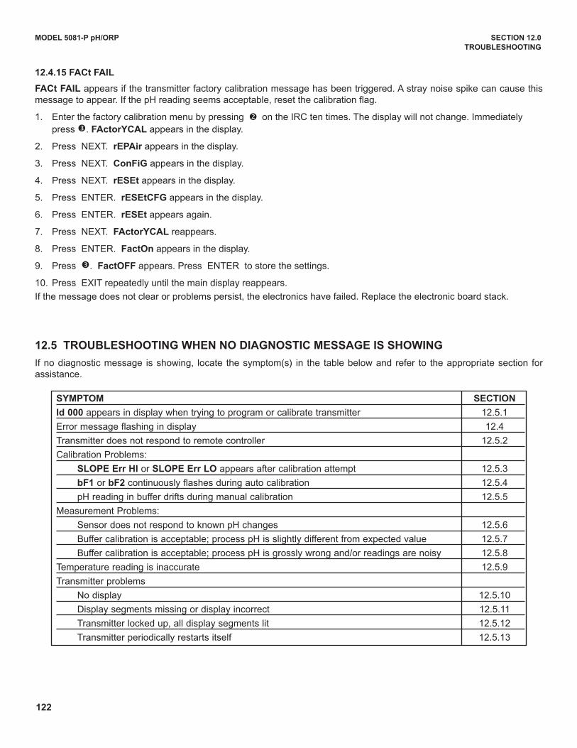
122
MODEL 5081-P pH/ORP SECTION 12.0
TROUBLESHOOTING
SyMPTOM SECTION
Id 000 appears in display when trying to program or calibrate transmitter 12.5.1
Error message flashing in display 12.4
Transmitter does not respond to remote controller 12.5.2
Calibration Problems:
SLOPE Err HI or SLOPE Err LO appears after calibration attempt 12.5.3
bF1 or bF2 continuously flashes during auto calibration 12.5.4
pH reading in buffer drifts during manual calibration 12.5.5
Measurement Problems:
Sensor does not respond to known pH changes 12.5.6
Buffer calibration is acceptable; process pH is slightly different from expected value 12.5.7
Buffer calibration is acceptable; process pH is grossly wrong and/or readings are noisy 12.5.8
Temperature reading is inaccurate 12.5.9
Transmitter problems
No display 12.5.10
display segments missing or display incorrect 12.5.11
Transmitter locked up, all display segments lit 12.5.12
Transmitter periodically restarts itself 12.5.13
12.4.15 FACt FAIL
FACt FAIL appears if the transmitter factory calibration message has been triggered. A stray noise spike can cause thismessage to appear. If the pH reading seems acceptable, reset the calibration flag.
1. Enter the factory calibration menu by pressing ç on the IRC ten times. The display will not change. Immediately press é. FActoryCAL appears in the display.
2. Press NEXT. rEPAir appears in the display.
3. Press NEXT. ConFiG appears in the display.
4. Press NEXT. rESEt appears in the display.
5. Press ENTER. rESEtCFG appears in the display.
6. Press ENTER. rESEt appears again.
7. Press NEXT. FActoryCAL reappears.
8. Press ENTER. FactOn appears in the display.
9. Press é. FactOFF appears. Press ENTER to store the settings.
10. Press EXIT repeatedly until the main display reappears.
If the message does not clear or problems persist, the electronics have failed. Replace the electronic board stack.
12.5 TROUBLESHOOTING wHEN NO DIAGNOSTIC MESSAGE IS SHOwING
If no diagnostic message is showing, locate the symptom(s) in the table below and refer to the appropriate section forassistance.
123
MODEL 5081-P pH/ORP SECTION 12.0
TROUBLESHOOTING
12.5.1 Id 000 in Display
A security code has been programmed into the transmitter. The correct code must be entered before the transmittercan be programmed or calibrated. To retrieve a lost security code see Section 5.8. To change the security code, seeSection 5.8.
12.5.2 Transmitter Does Not Respond to Infrared Remote Controller (IRC)
A. Be sure the transmitter is receiving the signal.
1. Clean the window in front of the IR detector. The detector is a small rectangle just above the main display
2. Hold the IRC at least six feet from the transmitter and not more than 15 degrees from the center.
3. Hold the IRC closer (within two feet) in case the batteries are getting weak.
B. If step A fails to help, check the IRC.
1. If a second Model 5081-P transmitter is available, test the IRC on that transmitter. If a spare transmitter is not available, continue with step 2.
2. The green LEd, located just above and between the RESET and HOLd buttons, should light when a key is pressed. A piece of black rubber film may be covering the LEd. Scrape the film away with your fingernail to expose the LEd. The two clear LEds on the front end of the IRC never light. They transmit the invisible IR signal.
3. If the green LEd does not light, the IRC is not working. Go to step C.
C. Take the IRC to a non-hazardous area and replace the two 1.5 Vdc AAA batteries.
If the green LEd lights, but the transmitter still does not respond, go to step d.
If neither the LEd lights nor the transmitter responds, replace the IRC.
d. Replace the transmitter display board.
12.5.3 SLOPE Err LO or SLOPE Err HI Appear After Calibration Attempt
Refer to Section 12.4.9 and Section 12.4.10 for assistance in solving calibration slope problems.
12.5.4 bF1 or bF2 Continuously Flashes During Auto Calibration
during autocalibration, bF1 or bF2 flashes until the pH reading of the sensor in buffer is stable.
A. Check the stability limits set in Section 8.7. If the stabilization range (prompt PH) is set too narrow or the stabilization time (prompt tIME) is set too long, the transmitter will not accept buffer readings. A good choice for PH is 0.02, and a good choice for tIME is 10 - 20 seconds.
B. Allow adequate time for the temperature of the sensor to reach the temperature of the buffer. If the sensor was in a process substantially hotter or colder than the buffer, allow at least 20 minutes for readings in the buffer to stabilize. Alternatively, place the sensor in a container of water at ambient temperature for 20 minutes before starting the calibration.
C. Be sure to swirl sensor after placing it in each new buffer solution.
d. Finally, check the sensor. Verify that wiring is correct. Also, the sensor may be dirty or aged, or the reference junction may be depleted.
1. Check that the sensor is properly wired to the transmitter. See Section 3.0. Pay particular attention to terminals TB-10 (mV in), TB-7 (reference), and TB-8 (solution ground).
2. See Section 11.3 for cleaning procedures.
3. If the sensor is not rebuildable, see Section 11.3.4 for a method of rejuvenating the reference junction.
4. If the sensor is rebuildable, replenish the reference electrolyte and replace the liquid junction.
5. Replace the sensor. A clean pH sensor should not drift in buffer.
124
MODEL 5081-P pH/ORP SECTION 12.0
TROUBLESHOOTING
12.5.5 pH Reading in Buffer Drifts During Manual Calibration
A. Allow adequate time for the temperature of the sensor to reach the temperature of the buffer. If the sensor was in a process substantially hotter or colder than the buffer, allow at least 20 minutes for readings in the buffer to stabilize. Alternatively, place the sensor in a container of water at ambient temperature for 20 minutes before starting the calibration.
B. Be sure to swirl sensor after placing it in each new buffer solution.
C. Finally, check the sensor. Verify that wiring is correct. Also, the sensor may be dirty or aged, or the reference junction may be depleted.
1. Check that the sensor is properly wired to the transmitter. See Section 3.0. Pay particular attention to terminals TB-10 (mV in), TB-7 (reference), and TB-8 (solution ground).
2. See Section 11.3 for cleaning procedures.
3. If the sensor is not rebuildable, see Section 11.3.4 for a method of rejuvenating the reference junction.
4. If the sensor is rebuildable, replenish the reference electrolyte and replace the liquid junction.
5. Replace the sensor. A clean pH sensor should not drift in buffer.
12.5.6 Sensor Does Not Respond To Known pH Changes
A. Verify that the change really happened. If pH response was being checked in buffers, recheck performance with freshbuffers. If a process pH reading was not what was expected, check the performance of the sensor in buffers. Also, use a second pH meter to verify that the expected change in the process pH really occurred.
B. Check the sensor. Verify that wiring is correct. Also, the sensor may be dirty or aged, or the reference junction may bedepleted.
1. Check that the sensor is properly wired to the transmitter. See Section 3.0. Pay particular attention to terminals TB-10 (mV in), TB-7 (reference), and TB-8 (solution ground).
2. See Section 11.3 for cleaning procedures.
C. If a clean, properly wired sensor does not respond to pH changes, the glass bulb is probably broken or cracked.
If a spare sensor is available, check the spare.
If the spare sensor responds to pH changes, the old sensor has failed.
If the spare sensor does not respond to pH changes, go to step d.
If a spare sensor is not available, check the glass impedance (GIMP) of the existing sensor. See Section 11.7.
If the impedance is less than about 20 megohm, the pH glass is cracked. Replace the sensor.
If the impedance is greater than about 20 megohm, go to step d.
d. Check transmitter performance by simulating pH inputs. See Section 12.8.
If the transmitter responds to simulated inputs, the problem must lie with the sensor or the interconnecting wiring. Verify the interconnecting wiring point to point. Fix or replace bad cable. If cable is good, replace the pH sensor.
If the transmitter does not respond to simulated inputs, replace the board stack.
12.5.7 Buffer Calibration Is Acceptable; Process pH is Slightly Different from Expected value.
differences between pH readings made with an on-line instrument and a laboratory or portable instrument are normal.The on-line instrument is subject to process variables, for example grounding potentials, stray voltages, and orientationeffects, that do not affect the laboratory or portable instrument. To make the Model 5081-P pH/ORP transmitter match thereading from a second pH meter refer to Section 7.7.
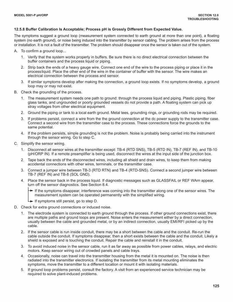
125
MODEL 5081-P pH/ORP SECTION 12.0
TROUBLESHOOTING
12.5.8 Buffer Calibration Is Acceptable; Process pH is Grossly Different from Expected value.
The symptoms suggest a ground loop (measurement system connected to earth ground at more than one point), a floatingsystem (no earth ground), or noise being induced into the transmitter by sensor cabling. The problem arises from the processor installation. It is not a fault of the transmitter. The problem should disappear once the sensor is taken out of the system.
A. To confirm a ground loop...
1. Verify that the system works properly in buffers. Be sure there is no direct electrical connection between the buffer containers and the process liquid or piping.
2. Strip back the ends of a heavy gauge wire. Connect one end of the wire to the process piping or place it in the processliquid. Place the other end of the wire in the container of buffer with the sensor. The wire makes an electrical connection between the process and sensor.
3. If similar symptoms develop after making the connection, a ground loop exists. If no symptoms develop, a groundloop may or may not exist.
B. Check the grounding of the process.
1. The measurement system needs one path to ground: through the process liquid and piping. Plastic piping, fiberglass tanks, and ungrounded or poorly grounded vessels do not provide a path. A floating system can pick up stray voltages from other electrical equipment.
2. Ground the piping or tank to a local earth ground. Metal tees, grounding rings, or grounding rods may be required.
3. If problems persist, connect a wire from the the ground connection at the dc power supply to the transmitter case.Connect a second wire from the transmitter case to the process. These connections force the grounds to the same potential.
4. If the problem persists, simple grounding is not the problem. Noise is probably being carried into the instrument through the sensor wiring. Go to step C.
C. Simplify the sensor wiring.
1. disconnect all sensor wires at the transmitter except: TB-4 (RTd SNS), TB-5 (RTd IN), TB-7 (REF IN), and TB-10(pH/ORP IN). If a remote preamplifier is being used, disconnect the wires at the input side of the junction box.
2. Tape back the ends of the disconnected wires, including all shield and drain wires, to keep them from making accidental connections with other wires, terminals, or the transmitter case.
3. Connect a jumper wire between TB-3 (RTd RTN) and TB-4 (RTd-SNS). Connect a second jumper wire between TB-7 (REF IN) and TB-8 (SOL GNd).
4. Place the sensor back in the process liquid. If diagnostic messages such as GLASSFAIL or REF WArn appear, turn off the sensor diagnostics. See Section 8.4.
If the symptoms disappear, interference was coming into the transmitter along one of the sensor wires. The measurement system can be operated permanently with the simplified wiring.
If symptoms still persist, go to step d.
d. Check for extra ground connections or induced noise.
1. The electrode system is connected to earth ground through the process. If other ground connections exist, there are multiple paths and ground loops are present. Noise enters the measurement either by a direct connection, usually between the cable and grounded metal, or by an indirect connection, usually EMI/RFI picked up by the cable.
2. If the sensor cable is run inside conduit, there may be a short between the cable and the conduit. Re-run the cable outside the conduit. If symptoms disappear, then a short exists between the cable and the conduit. Likely a shield is exposed and is touching the conduit. Repair the cable and reinstall it in the conduit.
3. To avoid induced noise in the sensor cable, run it as far away as possible from power cables, relays, and electric motors. Keep sensor wiring out of crowded panels and cable trays.
4. Occasionally, noise can travel into the transmitter housing from the metal it is mounted on. The noise is then radiated into the transmitter electronics. If isolating the transmitter from its metal mounting eliminates the symptoms, move the transmitter to a different location or mount it with isolating materials.
5. If ground loop problems persist, consult the factory. A visit from an experienced service technician may be required to solve plant-induced problems.
126
MODEL 5081-P pH/ORP SECTION 12.0
TROUBLESHOOTING
12.5.9 Temperature Reading Is Inaccurate
A. To troubleshoot temperature problems refer, to Section 12.4.6.
B. To calibrate the temperature response of the sensor, refer to Section 6.4.
C. If necessary, automatic temperature compensation can be temporarily disabled and the transmitter placed in manual temperature compensation. Refer to Section 8.5. For manual temperature, choose a temperature equal to the average temperature of the process. The resulting pH reading will be in error. The more variable the temperature and the further from pH 7,the greater the error.
12.5.10 HART Communications Problems
A. If the Model 375 or 475 Communicator software does not recognize the Model 5081pH/ORP transmitter, order an upgrade from Rosemount Measurement at (800) 999-9307.
B. Be sure the HART load and voltage requirements are met.
1. HART communications requires a minimum 250 ohm load in the current loop.
2. Install a 250-500 ohm resistor in series with the current loop. Check the actual resistor value with an ohmmeter.
3. For HART communications, the power supply voltage must be at least 18 Vdc. See Section 2.4.
C. Be sure the HART Communicator is properly connected.
1. The Communicator leads must be connected across the load.
2. The Communicator can be connected across the power terminals (TB-15 and TB-16).
d. Verify that the Model 375 or 475 is working correctly by testing it on another HART Smart device.
1. If the Communicator is working, the transmitter electronics may have failed. Call Rosemount Analytical for assistance.
2. If the Communicator seems to be malfunctioning, call Rosemount Measurement at (800) 999-9307 for assistance.
12.5.11 No Display
A. Be sure power requirements are being met.
1. The positive voltage lead must be connected to TB-16.
2. Check dc voltage requirements and load restrictions. Refer to Section 2.5.
B. Check for bad connections between the circuit boards. Refer to Section 2.2. Be sure the ribbon cable between the display and CPu boards is firmly seated in the socket on the CPu board. Be sure the socket connection between the CPu and analog boards is firm.
12.5.12 Display Segments Missing
Replace the display board.
12. 5.13 Transmitter Locks Up
A. Turn the dc power off, then turn it back on.
B. If the problem persists, replace the electronic board stack (PN 23992-02, HT; PN 23992-03, FF).
12. 5.14 Transmitter Periodically Restarts Itself
A. The problem is usually related to improperly wired RTd input terminals.
1. The RTd return wire must be connected to TB-3. The RTd sense wire must be connected to TB-4, and the RTd in wire must be connected to TB-5. See the wiring diagrams in Section 3.0. If the pH sensor does not have an RTd, connect a jumper wire across the terminals TB-3 and TB-4 and a second jumper across TB-4 and TB-5.
2. If the RTd connections have been jumpered as described in step B, automatic temperature compensation must be turned off and the transmitter operated in manual temperature mode. See Section 7.4 for the procedure.
B. If RTd wiring is correct and problems still persist.
1. Monitor the dc power supply. Be sure the power is not intermittent and the correct voltage is present. See Section 2.5.
2. Try connecting the transmitter to a different power supply.
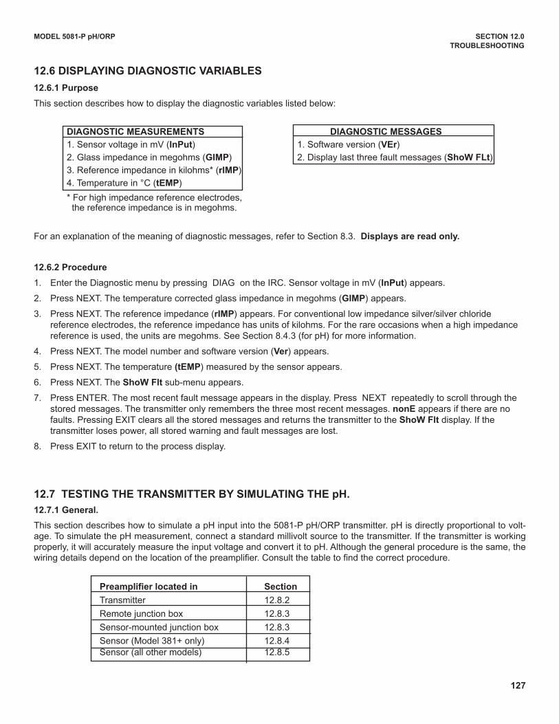
127
MODEL 5081-P pH/ORP SECTION 12.0
TROUBLESHOOTING
12.6 DISPLAyING DIAGNOSTIC vARIABLES
12.6.1 Purpose
This section describes how to display the diagnostic variables listed below:
DIAGNOSTIC MEASUREMENTS DIAGNOSTIC MESSAGES
1. Sensor voltage in mV (InPut) 1. Software version (vEr)
2. Glass impedance in megohms (GIMP) 2. display last three fault messages (Show FLt)
3. Reference impedance in kilohms* (rIMP)
4. Temperature in °C (tEMP)
* For high impedance reference electrodes, the reference impedance is in megohms.
For an explanation of the meaning of diagnostic messages, refer to Section 8.3. Displays are read only.
12.6.2 Procedure
1. Enter the diagnostic menu by pressing dIAG on the IRC. Sensor voltage in mV (InPut) appears.
2. Press NEXT. The temperature corrected glass impedance in megohms (GIMP) appears.
3. Press NEXT. The reference impedance (rIMP) appears. For conventional low impedance silver/silver chloride reference electrodes, the reference impedance has units of kilohms. For the rare occasions when a high impedance reference is used, the units are megohms. See Section 8.4.3 (for pH) for more information.
4. Press NEXT. The model number and software version (ver) appears.
5. Press NEXT. The temperature (tEMP) measured by the sensor appears.
6. Press NEXT. The Show Flt sub-menu appears.
7. Press ENTER. The most recent fault message appears in the display. Press NEXT repeatedly to scroll through the stored messages. The transmitter only remembers the three most recent messages. nonE appears if there are no faults. Pressing EXIT clears all the stored messages and returns the transmitter to the Show Flt display. If the transmitter loses power, all stored warning and fault messages are lost.
8. Press EXIT to return to the process display.
12.7 TESTING THE TRANSMITTER By SIMULATING THE pH.
12.7.1 General.
This section describes how to simulate a pH input into the 5081-P pH/ORP transmitter. pH is directly proportional to volt-age. To simulate the pH measurement, connect a standard millivolt source to the transmitter. If the transmitter is workingproperly, it will accurately measure the input voltage and convert it to pH. Although the general procedure is the same, thewiring details depend on the location of the preamplifier. Consult the table to find the correct procedure.
Preamplifier located in Section
Transmitter 12.8.2
Remote junction box 12.8.3
Sensor-mounted junction box 12.8.3
Sensor (Model 381+ only) 12.8.4Sensor (all other models) 12.8.5
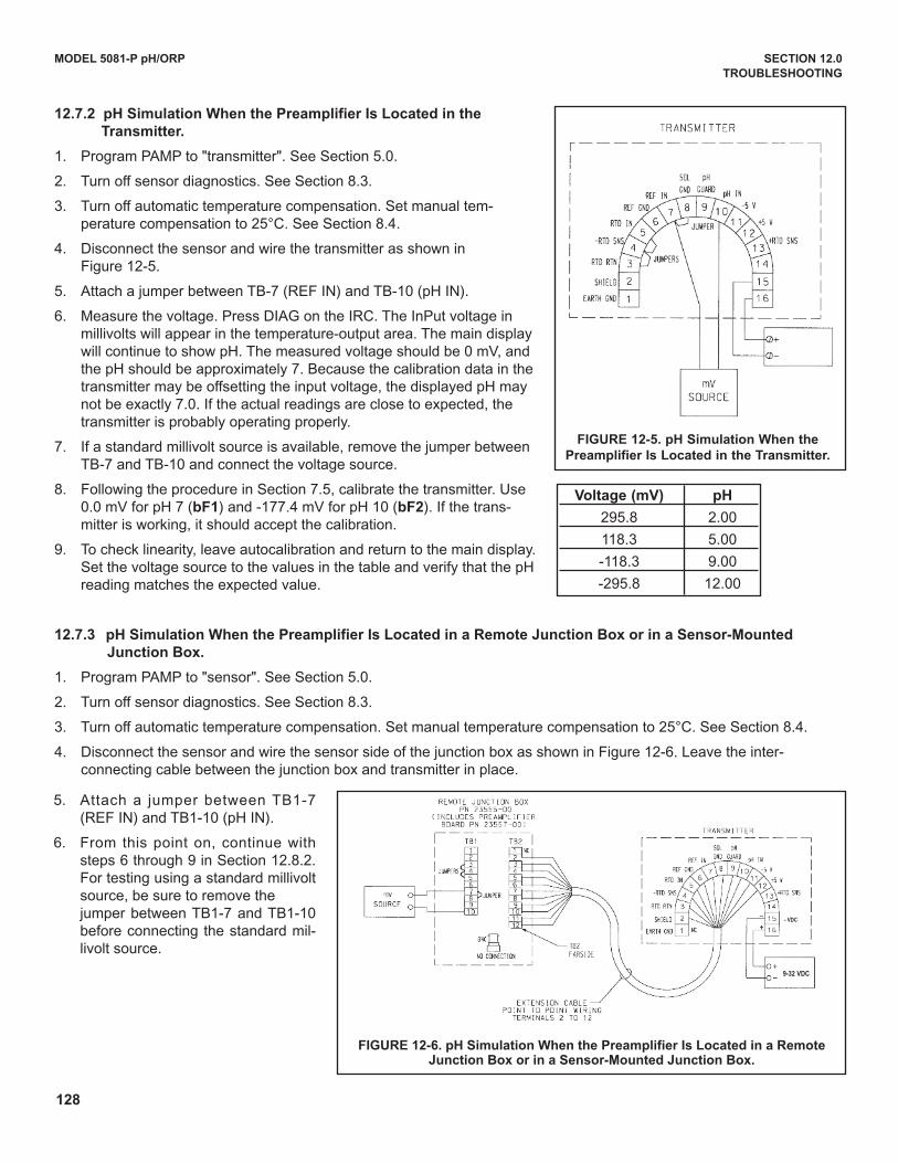
128
MODEL 5081-P pH/ORP SECTION 12.0
TROUBLESHOOTING
12.7.2 pH Simulation when the Preamplifier Is Located in the
Transmitter.
1. Program PAMP to "transmitter". See Section 5.0.
2. Turn off sensor diagnostics. See Section 8.3.
3. Turn off automatic temperature compensation. Set manual tem-perature compensation to 25°C. See Section 8.4.
4. disconnect the sensor and wire the transmitter as shown in Figure 12-5.
5. Attach a jumper between TB-7 (REF IN) and TB-10 (pH IN).
6. Measure the voltage. Press dIAG on the IRC. The InPut voltage in millivolts will appear in the temperature-output area. The main display will continue to show pH. The measured voltage should be 0 mV, and the pH should be approximately 7. Because the calibration data in the transmitter may be offsetting the input voltage, the displayed pH may not be exactly 7.0. If the actual readings are close to expected, the transmitter is probably operating properly.
7. If a standard millivolt source is available, remove the jumper between TB-7 and TB-10 and connect the voltage source.
8. Following the procedure in Section 7.5, calibrate the transmitter. use 0.0 mV for pH 7 (bF1) and -177.4 mV for pH 10 (bF2). If the trans-mitter is working, it should accept the calibration.
9. To check linearity, leave autocalibration and return to the main display. Set the voltage source to the values in the table and verify that the pH reading matches the expected value.
12.7.3 pH Simulation when the Preamplifier Is Located in a Remote Junction Box or in a Sensor-Mounted
Junction Box.
1. Program PAMP to "sensor". See Section 5.0.
2. Turn off sensor diagnostics. See Section 8.3.
3. Turn off automatic temperature compensation. Set manual temperature compensation to 25°C. See Section 8.4.
4. disconnect the sensor and wire the sensor side of the junction box as shown in Figure 12-6. Leave the inter-connecting cable between the junction box and transmitter in place.
FIGURE 12-6. pH Simulation when the Preamplifier Is Located in a RemoteJunction Box or in a Sensor-Mounted Junction Box.
voltage (mv) pH
295.8 2.00
118.3 5.00
-118.3 9.00
-295.8 12.00
FIGURE 12-5. pH Simulation when the
Preamplifier Is Located in the Transmitter.
5. Attach a jumper between TB1-7(REF IN) and TB1-10 (pH IN).
6. From this point on, continue withsteps 6 through 9 in Section 12.8.2.For testing using a standard millivoltsource, be sure to remove the jumper between TB1-7 and TB1-10before connecting the standard mil-livolt source.
- VDC
9-32 VDC
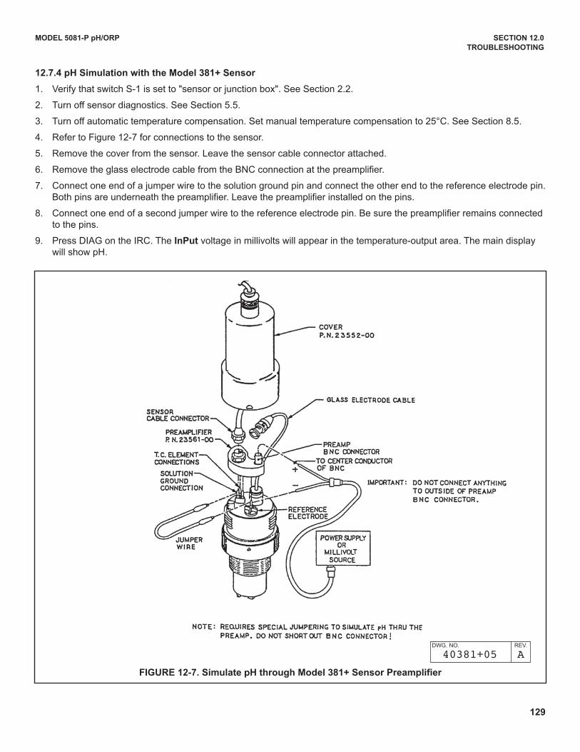
129
MODEL 5081-P pH/ORP SECTION 12.0
TROUBLESHOOTING
FIGURE 12-7. Simulate pH through Model 381+ Sensor Preamplifier
dWG. NO. REV.
40381+05 A
12.7.4 pH Simulation with the Model 381+ Sensor
1. Verify that switch S-1 is set to "sensor or junction box". See Section 2.2.
2. Turn off sensor diagnostics. See Section 5.5.
3. Turn off automatic temperature compensation. Set manual temperature compensation to 25°C. See Section 8.5.
4. Refer to Figure 12-7 for connections to the sensor.
5. Remove the cover from the sensor. Leave the sensor cable connector attached.
6. Remove the glass electrode cable from the BNC connection at the preamplifier.
7. Connect one end of a jumper wire to the solution ground pin and connect the other end to the reference electrode pin.Both pins are underneath the preamplifier. Leave the preamplifier installed on the pins.
8. Connect one end of a second jumper wire to the reference electrode pin. Be sure the preamplifier remains connected to the pins.
9. Press dIAG on the IRC. The InPut voltage in millivolts will appear in the temperature-output area. The main display will show pH.
130
MODEL 5081-P pH/ORP SECTION 12.0
TROUBLESHOOTING
10. Touch the other end of the second jumper to the center pin of the BNC connector on the preamplifier. dO NOT LET THE WIRE TOuCH THE OuTSIdE OF THE BNC CONNECTOR.
11. Measure the voltage. The measured voltage should be 0 mV, and the pH should be approximately 7. Because the calibration data in the transmitter may be offsetting the input voltage, the displayed pH may not be exactly 7.0. If the actual readings are close to expected, the transmitter is probably working fine.
12. If a standard millivolt source is available, use it to perform a simulated calibration.
13. Remove the jumper used to connect the reference pin to the center pin of the BNC. Connect the negative terminal of the standard millivolt source to the reference pin and connect the positive terminal to the center pin of the BNC. dO NOT LET THE WIRE TOuCH THE OuTSIdE OF THE BNC CONNECTOR.
14. Following the autocalibration procedure in Section 7.5, calibrate the transmitter. use 0.0 mV for pH 7 (bF1) and -177.4 mV for pH 10 (bF2). If the transmitter is working, it should accept the calibration.
15. To check linearity, leave autocalibration and return to the main display. Set the voltage source to the values in the table and verify that the pH reading matches the expected value.
12.7.5 pH Simulation when Preamplifier is in Sensor
The preamplifier in the sensor simply converts the high impedence signal into a low impedance signal without amplifyingit. To simulate pH values, use the procedure in Section 12.8.
12.8 FACTORy ASSISTANCE AND REPAIRS
12.8.1 Troubleshooting Assistance.
For assistance in correcting transmitter, sensor, and measurement problems...
- in the united States call Emerson Process Management Liquid division at (800) 854-8527.
- outside the united States call the nearest Emerson Process Management office. See the back page of the manual.
12.8.2 Return of Materials
If it is necessary to return the transmitter to the factory for repairs...
- in the united States call Emerson Process Management Liquid division at (800) 854-8257.
- outside the united States call the nearest Emerson Process Management office. See the back page of the manual.
Always call before returning material. Do not send anything without obtaining a Return Material Authorization
(RMA) number.
voltage (mv) pH
295.8 2.00
118.3 5.00
-118.3 9.00
-295.8 12.00
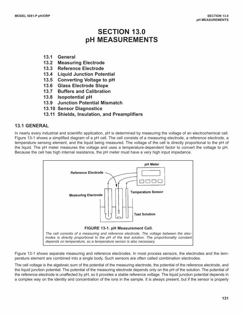
131
SECTION 13.0pH MEASUREMENTS
13.1 General
13.2 Measuring Electrode
13.3 Reference Electrode
13.4 Liquid Junction Potential
13.5 Converting voltage to pH
13.6 Glass Electrode Slope
13.7 Buffers and Calibration
13.8 Isopotential pH
13.9 Junction Potential Mismatch
13.10 Sensor Diagnostics
13.11 Shields, Insulation, and Preamplifiers
13.1 GENERAL
In nearly every industrial and scientific application, pH is determined by measuring the voltage of an electrochemical cell.Figure 13-1 shows a simplified diagram of a pH cell. The cell consists of a measuring electrode, a reference electrode, atemperature sensing element, and the liquid being measured. The voltage of the cell is directly proportional to the pH ofthe liquid. The pH meter measures the voltage and uses a temperature-dependent factor to convert the voltage to pH.Because the cell has high internal resistance, the pH meter must have a very high input impedance.
Figure 13-1 shows separate measuring and reference electrodes. In most process sensors, the electrodes and the tem-perature element are combined into a single body. Such sensors are often called combination electrodes.
The cell voltage is the algebraic sum of the potential of the measuring electrode, the potential of the reference electrode, andthe liquid junction potential. The potential of the measuring electrode depends only on the pH of the solution. The potential ofthe reference electrode is unaffected by pH, so it provides a stable reference voltage. The liquid junction potential depends ina complex way on the identity and concentration of the ions in the sample. It is always present, but if the sensor is properly
MODEL 5081-P pH/ORP SECTION 13.0
pH MEASUREMENTS
FIGURE 13-1. pH Measurement Cell.
The cell consists of a measuring and reference electrode. The voltage between the elec-trodes is directly proportional to the pH of the test solution. The proportionality constantdepends on temperature, so a temperature sensor is also necessary.
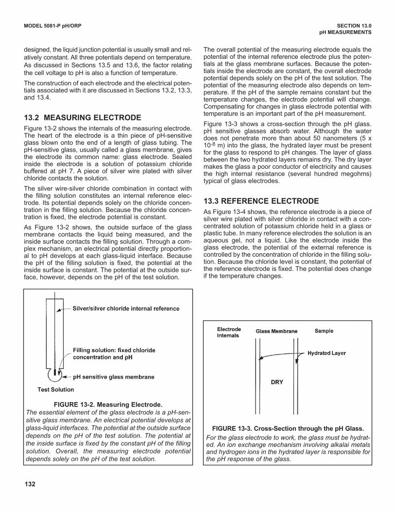
132
MODEL 5081-P pH/ORP SECTION 13.0
pH MEASUREMENTS
designed, the liquid junction potential is usually small and rel-atively constant. All three potentials depend on temperature.As discussed in Sections 13.5 and 13.6, the factor relatingthe cell voltage to pH is also a function of temperature.
The construction of each electrode and the electrical poten-tials associated with it are discussed in Sections 13.2, 13.3,and 13.4.
13.2 MEASURING ELECTRODE
Figure 13-2 shows the internals of the measuring electrode.The heart of the electrode is a thin piece of pH-sensitiveglass blown onto the end of a length of glass tubing. ThepH-sensitive glass, usually called a glass membrane, givesthe electrode its common name: glass electrode. Sealedinside the electrode is a solution of potassium chloridebuffered at pH 7. A piece of silver wire plated with silverchloride contacts the solution.
The silver wire-silver chloride combination in contact withthe filling solution constitutes an internal reference elec-trode. Its potential depends solely on the chloride concen-tration in the filling solution. Because the chloride concen-tration is fixed, the electrode potential is constant.
As Figure 13-2 shows, the outside surface of the glassmembrane contacts the liquid being measured, and theinside surface contacts the filling solution. Through a com-plex mechanism, an electrical potential directly proportion-al to pH develops at each glass-liquid interface. Becausethe pH of the filling solution is fixed, the potential at theinside surface is constant. The potential at the outside sur-face, however, depends on the pH of the test solution.
The overall potential of the measuring electrode equals thepotential of the internal reference electrode plus the poten-tials at the glass membrane surfaces. Because the poten-tials inside the electrode are constant, the overall electrodepotential depends solely on the pH of the test solution. Thepotential of the measuring electrode also depends on tem-perature. If the pH of the sample remains constant but thetemperature changes, the electrode potential will change.Compensating for changes in glass electrode potential withtemperature is an important part of the pH measurement.
Figure 13-3 shows a cross-section through the pH glass.pH sensitive glasses absorb water. Although the waterdoes not penetrate more than about 50 nanometers (5 x10⁻⁸ m) into the glass, the hydrated layer must be presentfor the glass to respond to pH changes. The layer of glassbetween the two hydrated layers remains dry. The dry layermakes the glass a poor conductor of electricity and causesthe high internal resistance (several hundred megohms)typical of glass electrodes.
13.3 REFERENCE ELECTRODE
As Figure 13-4 shows, the reference electrode is a piece ofsilver wire plated with silver chloride in contact with a con-centrated solution of potassium chloride held in a glass orplastic tube. In many reference electrodes the solution is anaqueous gel, not a liquid. Like the electrode inside theglass electrode, the potential of the external reference iscontrolled by the concentration of chloride in the filling solu-tion. Because the chloride level is constant, the potential ofthe reference electrode is fixed. The potential does changeif the temperature changes.
FIGURE 13-2. Measuring Electrode.
The essential element of the glass electrode is a pH-sen-
sitive glass membrane. An electrical potential develops at
glass-liquid interfaces. The potential at the outside surface
depends on the pH of the test solution. The potential at
the inside surface is fixed by the constant pH of the filling
solution. Overall, the measuring electrode potential
depends solely on the pH of the test solution.
FIGURE 13-3. Cross-Section through the pH Glass.
For the glass electrode to work, the glass must be hydrat-ed. An ion exchange mechanism involving alkalai metalsand hydrogen ions in the hydrated layer is responsible forthe pH response of the glass.
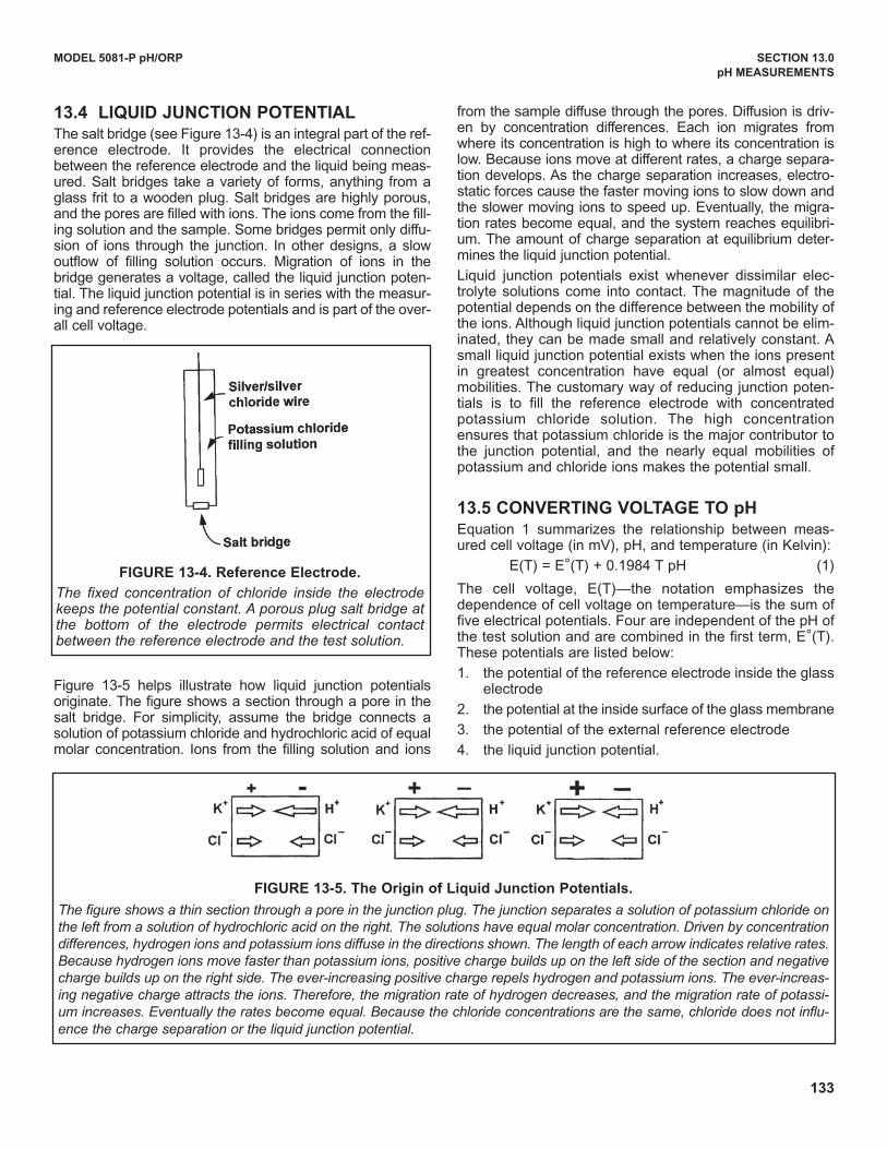
133
MODEL 5081-P pH/ORP SECTION 13.0
pH MEASUREMENTS
FIGURE 13-5. The Origin of Liquid Junction Potentials.
The figure shows a thin section through a pore in the junction plug. The junction separates a solution of potassium chloride on
the left from a solution of hydrochloric acid on the right. The solutions have equal molar concentration. Driven by concentration
differences, hydrogen ions and potassium ions diffuse in the directions shown. The length of each arrow indicates relative rates.
Because hydrogen ions move faster than potassium ions, positive charge builds up on the left side of the section and negative
charge builds up on the right side. The ever-increasing positive charge repels hydrogen and potassium ions. The ever-increas-
ing negative charge attracts the ions. Therefore, the migration rate of hydrogen decreases, and the migration rate of potassi-
um increases. Eventually the rates become equal. Because the chloride concentrations are the same, chloride does not influ-
ence the charge separation or the liquid junction potential.
13.4 LIQUID JUNCTION POTENTIALThe salt bridge (see Figure 13-4) is an integral part of the ref-erence electrode. It provides the electrical connectionbetween the reference electrode and the liquid being meas-ured. Salt bridges take a variety of forms, anything from aglass frit to a wooden plug. Salt bridges are highly porous,and the pores are filled with ions. The ions come from the fill-ing solution and the sample. Some bridges permit only diffu-sion of ions through the junction. In other designs, a slowoutflow of filling solution occurs. Migration of ions in thebridge generates a voltage, called the liquid junction poten-tial. The liquid junction potential is in series with the measur-ing and reference electrode potentials and is part of the over-all cell voltage.
Figure 13-5 helps illustrate how liquid junction potentialsoriginate. The figure shows a section through a pore in thesalt bridge. For simplicity, assume the bridge connects asolution of potassium chloride and hydrochloric acid of equalmolar concentration. Ions from the filling solution and ions
from the sample diffuse through the pores. diffusion is driv-en by concentration differences. Each ion migrates fromwhere its concentration is high to where its concentration islow. Because ions move at different rates, a charge separa-tion develops. As the charge separation increases, electro-static forces cause the faster moving ions to slow down andthe slower moving ions to speed up. Eventually, the migra-tion rates become equal, and the system reaches equilibri-um. The amount of charge separation at equilibrium deter-mines the liquid junction potential.
Liquid junction potentials exist whenever dissimilar elec-trolyte solutions come into contact. The magnitude of thepotential depends on the difference between the mobility ofthe ions. Although liquid junction potentials cannot be elim-inated, they can be made small and relatively constant. Asmall liquid junction potential exists when the ions presentin greatest concentration have equal (or almost equal)mobilities. The customary way of reducing junction poten-tials is to fill the reference electrode with concentratedpotassium chloride solution. The high concentrationensures that potassium chloride is the major contributor tothe junction potential, and the nearly equal mobilities ofpotassium and chloride ions makes the potential small.
13.5 CONvERTING vOLTAGE TO pHEquation 1 summarizes the relationship between meas-ured cell voltage (in mV), pH, and temperature (in Kelvin):
E(T) = E°(T) + 0.1984 T pH (1)
The cell voltage, E(T)—the notation emphasizes thedependence of cell voltage on temperature—is the sum offive electrical potentials. Four are independent of the pH ofthe test solution and are combined in the first term, E°(T).These potentials are listed below:
1. the potential of the reference electrode inside the glasselectrode
2. the potential at the inside surface of the glass membrane
3. the potential of the external reference electrode
4. the liquid junction potential.
FIGURE 13-4. Reference Electrode.
The fixed concentration of chloride inside the electrodekeeps the potential constant. A porous plug salt bridge atthe bottom of the electrode permits electrical contactbetween the reference electrode and the test solution.
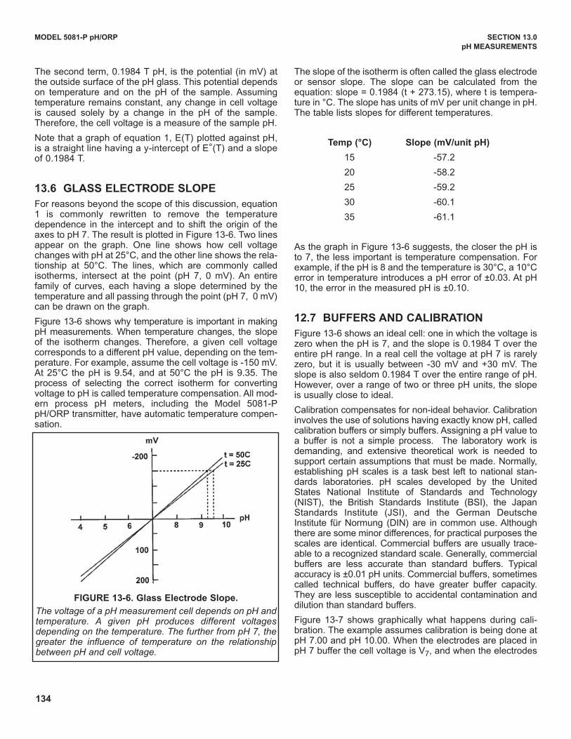
134
MODEL 5081-P pH/ORP SECTION 13.0
pH MEASUREMENTS
The second term, 0.1984 T pH, is the potential (in mV) atthe outside surface of the pH glass. This potential dependson temperature and on the pH of the sample. Assumingtemperature remains constant, any change in cell voltageis caused solely by a change in the pH of the sample.Therefore, the cell voltage is a measure of the sample pH.
Note that a graph of equation 1, E(T) plotted against pH,is a straight line having a y-intercept of E°(T) and a slopeof 0.1984 T.
13.6 GLASS ELECTRODE SLOPE
For reasons beyond the scope of this discussion, equation1 is commonly rewritten to remove the temperaturedependence in the intercept and to shift the origin of theaxes to pH 7. The result is plotted in Figure 13-6. Two linesappear on the graph. One line shows how cell voltagechanges with pH at 25°C, and the other line shows the rela-tionship at 50°C. The lines, which are commonly calledisotherms, intersect at the point (pH 7, 0 mV). An entirefamily of curves, each having a slope determined by thetemperature and all passing through the point (pH 7, 0 mV)can be drawn on the graph.
Figure 13-6 shows why temperature is important in makingpH measurements. When temperature changes, the slopeof the isotherm changes. Therefore, a given cell voltagecorresponds to a different pH value, depending on the tem-perature. For example, assume the cell voltage is -150 mV.At 25°C the pH is 9.54, and at 50°C the pH is 9.35. Theprocess of selecting the correct isotherm for convertingvoltage to pH is called temperature compensation. All mod-ern process pH meters, including the Model 5081-PpH/ORP transmitter, have automatic temperature compen-sation.
The slope of the isotherm is often called the glass electrodeor sensor slope. The slope can be calculated from theequation: slope = 0.1984 (t + 273.15), where t is tempera-ture in °C. The slope has units of mV per unit change in pH.The table lists slopes for different temperatures.
Temp (°C) Slope (mv/unit pH)
15 -57.2
20 -58.2
25 -59.2
30 -60.1
35 -61.1
As the graph in Figure 13-6 suggests, the closer the pH isto 7, the less important is temperature compensation. Forexample, if the pH is 8 and the temperature is 30°C, a 10°Cerror in temperature introduces a pH error of ±0.03. At pH10, the error in the measured pH is ±0.10.
12.7 BUFFERS AND CALIBRATION
Figure 13-6 shows an ideal cell: one in which the voltage iszero when the pH is 7, and the slope is 0.1984 T over theentire pH range. In a real cell the voltage at pH 7 is rarelyzero, but it is usually between -30 mV and +30 mV. Theslope is also seldom 0.1984 T over the entire range of pH.However, over a range of two or three pH units, the slopeis usually close to ideal.
Calibration compensates for non-ideal behavior. Calibrationinvolves the use of solutions having exactly know pH, calledcalibration buffers or simply buffers. Assigning a pH value toa buffer is not a simple process. The laboratory work isdemanding, and extensive theoretical work is needed tosupport certain assumptions that must be made. Normally,establishing pH scales is a task best left to national stan-dards laboratories. pH scales developed by the unitedStates National Institute of Standards and Technology(NIST), the British Standards Institute (BSI), the JapanStandards Institute (JSI), and the German deutscheInstitute für Normung (dIN) are in common use. Althoughthere are some minor differences, for practical purposes thescales are identical. Commercial buffers are usually trace-able to a recognized standard scale. Generally, commercialbuffers are less accurate than standard buffers. Typicalaccuracy is ±0.01 pH units. Commercial buffers, sometimescalled technical buffers, do have greater buffer capacity.They are less susceptible to accidental contamination anddilution than standard buffers.
Figure 13-7 shows graphically what happens during cali-bration. The example assumes calibration is being done atpH 7.00 and pH 10.00. When the electrodes are placed inpH 7 buffer the cell voltage is V7, and when the electrodes
FIGURE 13-6. Glass Electrode Slope.
The voltage of a pH measurement cell depends on pH andtemperature. A given pH produces different voltagesdepending on the temperature. The further from pH 7, thegreater the influence of temperature on the relationshipbetween pH and cell voltage.
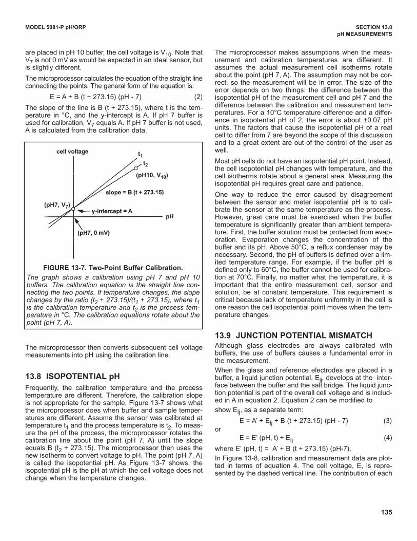
135
MODEL 5081-P pH/ORP SECTION 13.0
pH MEASUREMENTS
are placed in pH 10 buffer, the cell voltage is V10. Note thatV7 is not 0 mV as would be expected in an ideal sensor, butis slightly different.
The microprocessor calculates the equation of the straight lineconnecting the points. The general form of the equation is:
E = A + B (t + 273.15) (pH - 7) (2)
The slope of the line is B (t + 273.15), where t is the tem-perature in °C, and the y-intercept is A. If pH 7 buffer isused for calibration, V7 equals A. If pH 7 buffer is not used,A is calculated from the calibration data.
The microprocessor then converts subsequent cell voltagemeasurements into pH using the calibration line.
13.8 ISOPOTENTIAL pH
Frequently, the calibration temperature and the processtemperature are different. Therefore, the calibration slopeis not appropriate for the sample. Figure 13-7 shows whatthe microprocessor does when buffer and sample temper-atures are different. Assume the sensor was calibrated attemperature t1 and the process temperature is t2. To meas-ure the pH of the process, the microprocessor rotates thecalibration line about the point (pH 7, A) until the slopeequals B (t2 + 273.15). The microprocessor then uses thenew isotherm to convert voltage to pH. The point (pH 7, A)is called the isopotential pH. As Figure 13-7 shows, theisopotential pH is the pH at which the cell voltage does notchange when the temperature changes.
The microprocessor makes assumptions when the meas-urement and calibration temperatures are different. Itassumes the actual measurement cell isotherms rotateabout the point (pH 7, A). The assumption may not be cor-rect, so the measurement will be in error. The size of theerror depends on two things: the difference between theisopotential pH of the measurement cell and pH 7 and thedifference between the calibration and measurement tem-peratures. For a 10°C temperature difference and a differ-ence in isopotential pH of 2, the error is about ±0.07 pHunits. The factors that cause the isopotential pH of a realcell to differ from 7 are beyond the scope of this discussionand to a great extent are out of the control of the user aswell.
Most pH cells do not have an isopotential pH point. Instead,the cell isopotential pH changes with temperature, and thecell isotherms rotate about a general area. Measuring theisopotential pH requires great care and patience.
One way to reduce the error caused by disagreementbetween the sensor and meter isopotential pH is to cali-brate the sensor at the same temperature as the process.However, great care must be exercised when the buffertemperature is significantly greater than ambient tempera-ture. First, the buffer solution must be protected from evap-oration. Evaporation changes the concentration of thebuffer and its pH. Above 50°C, a reflux condenser may benecessary. Second, the pH of buffers is defined over a lim-ited temperature range. For example, if the buffer pH isdefined only to 60°C, the buffer cannot be used for calibra-tion at 70°C. Finally, no matter what the temperature, it isimportant that the entire measurement cell, sensor andsolution, be at constant temperature. This requirement iscritical because lack of temperature uniformity in the cell isone reason the cell isopotential point moves when the tem-perature changes.
13.9 JUNCTION POTENTIAL MISMATCHAlthough glass electrodes are always calibrated withbuffers, the use of buffers causes a fundamental error inthe measurement.
When the glass and reference electrodes are placed in abuffer, a liquid junction potential, Elj, develops at the inter-face between the buffer and the salt bridge. The liquid junc-tion potential is part of the overall cell voltage and is includ-ed in A in equation 2. Equation 2 can be modified to
show Elj, as a separate term:
E = A’ + Elj + B (t + 273.15) (pH - 7) (3)or
E = E’ (pH, t) + Elj (4)
where E’ (pH, t) = A’ + B (t + 273.15) (pH-7).
In Figure 13-8, calibration and measurement data are plot-ted in terms of equation 4. The cell voltage, E, is repre-sented by the dashed vertical line. The contribution of each
FIGURE 13-7. Two-Point Buffer Calibration.
The graph shows a calibration using pH 7 and pH 10buffers. The calibration equation is the straight line con-necting the two points. If temperature changes, the slopechanges by the ratio (t2 + 273.15)/(t1 + 273.15), where t1is the calibration temperature and t2 is the process tem-perature in °C. The calibration equations rotate about thepoint (pH 7, A).
t1
t2
(pH10, v10)
(pH7, v7)
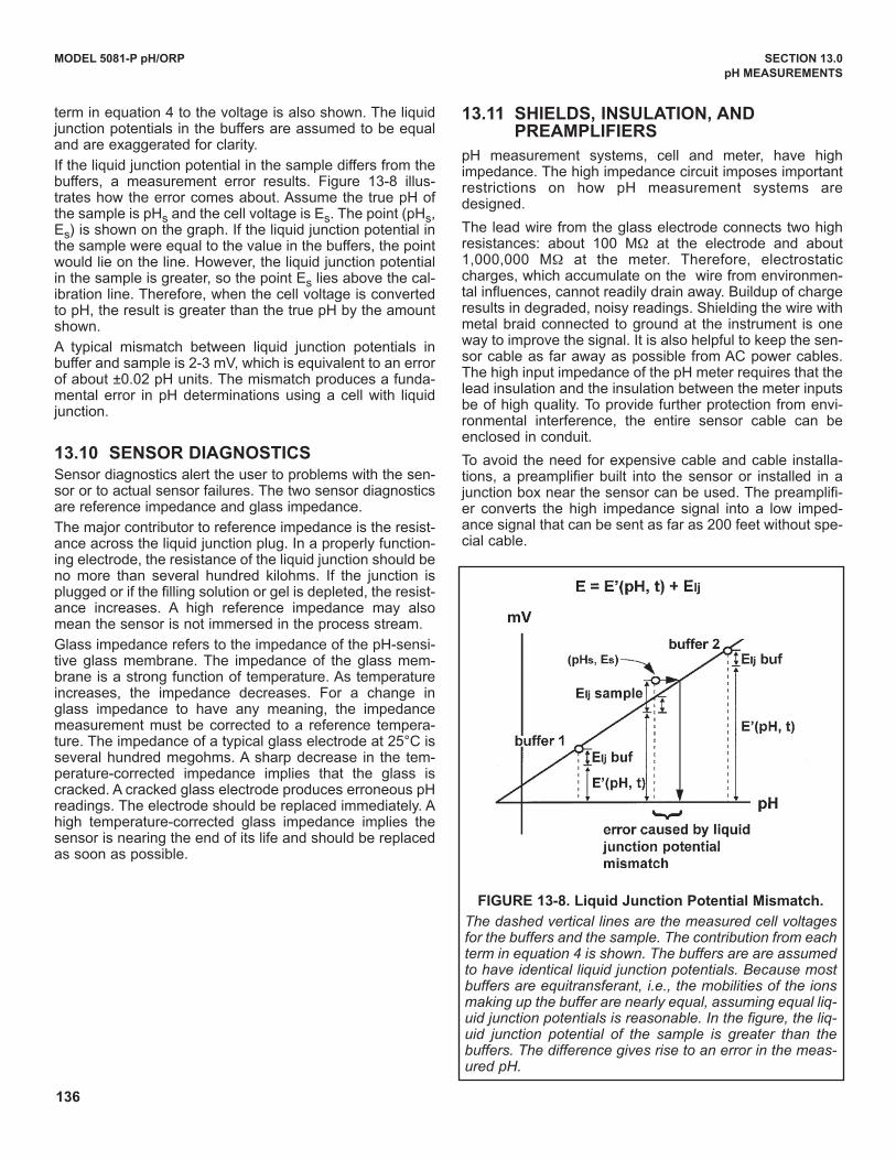
136
MODEL 5081-P pH/ORP SECTION 13.0
pH MEASUREMENTS
term in equation 4 to the voltage is also shown. The liquidjunction potentials in the buffers are assumed to be equaland are exaggerated for clarity.
If the liquid junction potential in the sample differs from thebuffers, a measurement error results. Figure 13-8 illus-trates how the error comes about. Assume the true pH ofthe sample is pHs and the cell voltage is Es. The point (pHs,Es) is shown on the graph. If the liquid junction potential inthe sample were equal to the value in the buffers, the pointwould lie on the line. However, the liquid junction potentialin the sample is greater, so the point Es lies above the cal-ibration line. Therefore, when the cell voltage is convertedto pH, the result is greater than the true pH by the amountshown.
A typical mismatch between liquid junction potentials inbuffer and sample is 2-3 mV, which is equivalent to an errorof about ±0.02 pH units. The mismatch produces a funda-mental error in pH determinations using a cell with liquidjunction.
13.10 SENSOR DIAGNOSTICSSensor diagnostics alert the user to problems with the sen-sor or to actual sensor failures. The two sensor diagnosticsare reference impedance and glass impedance.
The major contributor to reference impedance is the resist-ance across the liquid junction plug. In a properly function-ing electrode, the resistance of the liquid junction should beno more than several hundred kilohms. If the junction isplugged or if the filling solution or gel is depleted, the resist-ance increases. A high reference impedance may alsomean the sensor is not immersed in the process stream.
Glass impedance refers to the impedance of the pH-sensi-tive glass membrane. The impedance of the glass mem-brane is a strong function of temperature. As temperatureincreases, the impedance decreases. For a change inglass impedance to have any meaning, the impedancemeasurement must be corrected to a reference tempera-ture. The impedance of a typical glass electrode at 25°C isseveral hundred megohms. A sharp decrease in the tem-perature-corrected impedance implies that the glass iscracked. A cracked glass electrode produces erroneous pHreadings. The electrode should be replaced immediately. Ahigh temperature-corrected glass impedance implies thesensor is nearing the end of its life and should be replacedas soon as possible.
13.11 SHIELDS, INSULATION, AND PREAMPLIFIERS
pH measurement systems, cell and meter, have highimpedance. The high impedance circuit imposes importantrestrictions on how pH measurement systems aredesigned.
The lead wire from the glass electrode connects two highresistances: about 100 MW at the electrode and about1,000,000 MW at the meter. Therefore, electrostaticcharges, which accumulate on the wire from environmen-tal influences, cannot readily drain away. Buildup of chargeresults in degraded, noisy readings. Shielding the wire withmetal braid connected to ground at the instrument is oneway to improve the signal. It is also helpful to keep the sen-sor cable as far away as possible from AC power cables.The high input impedance of the pH meter requires that thelead insulation and the insulation between the meter inputsbe of high quality. To provide further protection from envi-ronmental interference, the entire sensor cable can beenclosed in conduit.
To avoid the need for expensive cable and cable installa-tions, a preamplifier built into the sensor or installed in ajunction box near the sensor can be used. The preamplifi-er converts the high impedance signal into a low imped-ance signal that can be sent as far as 200 feet without spe-cial cable.
FIGURE 13-8. Liquid Junction Potential Mismatch.
The dashed vertical lines are the measured cell voltagesfor the buffers and the sample. The contribution from eachterm in equation 4 is shown. The buffers are are assumedto have identical liquid junction potentials. Because mostbuffers are equitransferant, i.e., the mobilities of the ionsmaking up the buffer are nearly equal, assuming equal liq-uid junction potentials is reasonable. In the figure, the liq-uid junction potential of the sample is greater than thebuffers. The difference gives rise to an error in the meas-ured pH.
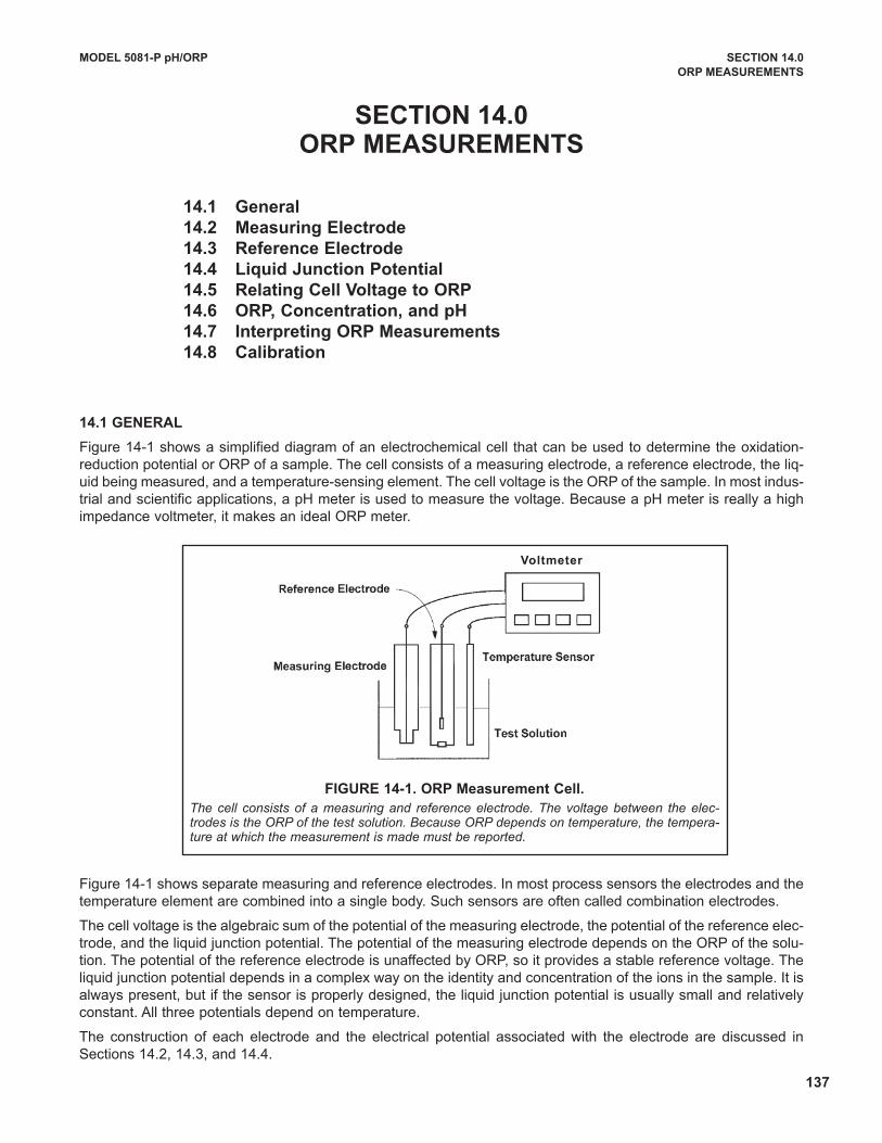
137
MODEL 5081-P pH/ORP SECTION 14.0
ORP MEASUREMENTS
SECTION 14.0ORP MEASUREMENTS
14.1 General
14.2 Measuring Electrode
14.3 Reference Electrode
14.4 Liquid Junction Potential
14.5 Relating Cell voltage to ORP
14.6 ORP, Concentration, and pH
14.7 Interpreting ORP Measurements
14.8 Calibration
14.1 GENERAL
Figure 14-1 shows a simplified diagram of an electrochemical cell that can be used to determine the oxidation-reduction potential or ORP of a sample. The cell consists of a measuring electrode, a reference electrode, the liq-uid being measured, and a temperature-sensing element. The cell voltage is the ORP of the sample. In most indus-trial and scientific applications, a pH meter is used to measure the voltage. Because a pH meter is really a highimpedance voltmeter, it makes an ideal ORP meter.
Figure 14-1 shows separate measuring and reference electrodes. In most process sensors the electrodes and thetemperature element are combined into a single body. Such sensors are often called combination electrodes.
The cell voltage is the algebraic sum of the potential of the measuring electrode, the potential of the reference elec-trode, and the liquid junction potential. The potential of the measuring electrode depends on the ORP of the solu-tion. The potential of the reference electrode is unaffected by ORP, so it provides a stable reference voltage. Theliquid junction potential depends in a complex way on the identity and concentration of the ions in the sample. It isalways present, but if the sensor is properly designed, the liquid junction potential is usually small and relativelyconstant. All three potentials depend on temperature.
The construction of each electrode and the electrical potential associated with the electrode are discussed inSections 14.2, 14.3, and 14.4.
FIGURE 14-1. ORP Measurement Cell.
The cell consists of a measuring and reference electrode. The voltage between the elec-trodes is the ORP of the test solution. Because ORP depends on temperature, the tempera-ture at which the measurement is made must be reported.
voltmeter
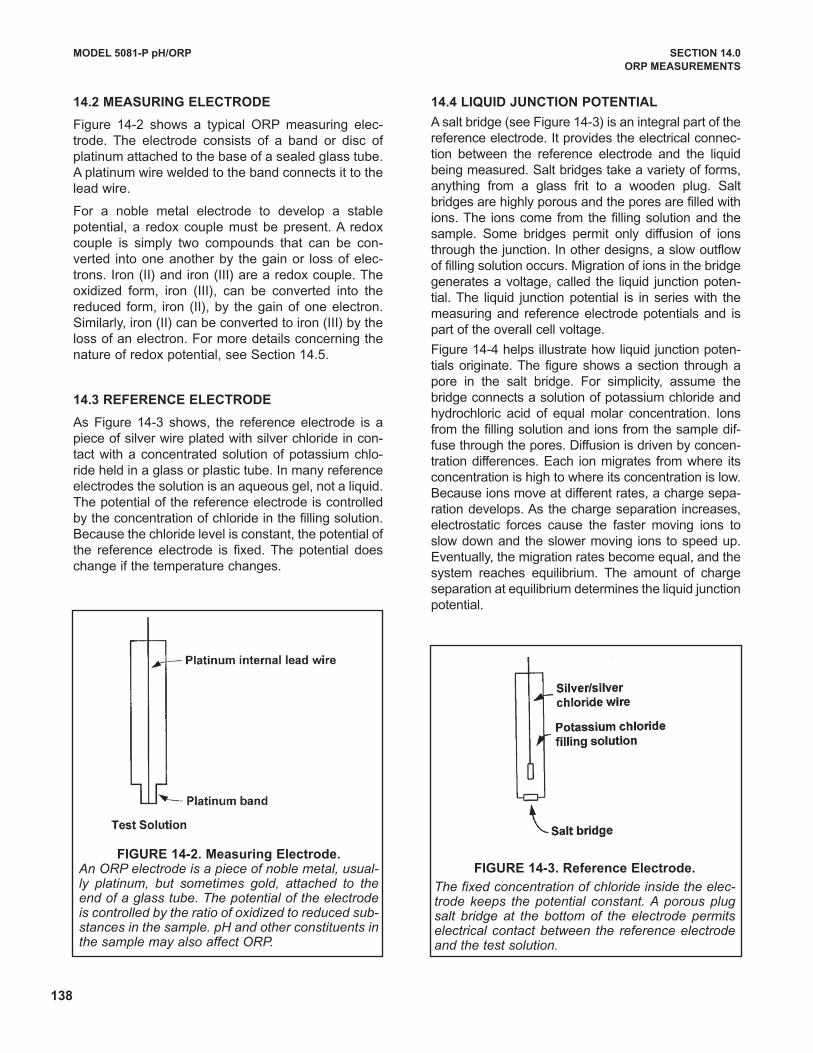
138
14.2 MEASURING ELECTRODE
Figure 14-2 shows a typical ORP measuring elec-trode. The electrode consists of a band or disc ofplatinum attached to the base of a sealed glass tube.A platinum wire welded to the band connects it to thelead wire.
For a noble metal electrode to develop a stablepotential, a redox couple must be present. A redoxcouple is simply two compounds that can be con-verted into one another by the gain or loss of elec-trons. Iron (II) and iron (III) are a redox couple. Theoxidized form, iron (III), can be converted into thereduced form, iron (II), by the gain of one electron.Similarly, iron (II) can be converted to iron (III) by theloss of an electron. For more details concerning thenature of redox potential, see Section 14.5.
14.3 REFERENCE ELECTRODE
As Figure 14-3 shows, the reference electrode is apiece of silver wire plated with silver chloride in con-tact with a concentrated solution of potassium chlo-ride held in a glass or plastic tube. In many referenceelectrodes the solution is an aqueous gel, not a liquid.The potential of the reference electrode is controlledby the concentration of chloride in the filling solution.Because the chloride level is constant, the potential ofthe reference electrode is fixed. The potential doeschange if the temperature changes.
14.4 LIQUID JUNCTION POTENTIAL
A salt bridge (see Figure 14-3) is an integral part of thereference electrode. It provides the electrical connec-tion between the reference electrode and the liquidbeing measured. Salt bridges take a variety of forms,anything from a glass frit to a wooden plug. Saltbridges are highly porous and the pores are filled withions. The ions come from the filling solution and thesample. Some bridges permit only diffusion of ionsthrough the junction. In other designs, a slow outflowof filling solution occurs. Migration of ions in the bridgegenerates a voltage, called the liquid junction poten-tial. The liquid junction potential is in series with themeasuring and reference electrode potentials and ispart of the overall cell voltage.
Figure 14-4 helps illustrate how liquid junction poten-tials originate. The figure shows a section through apore in the salt bridge. For simplicity, assume thebridge connects a solution of potassium chloride andhydrochloric acid of equal molar concentration. Ionsfrom the filling solution and ions from the sample dif-fuse through the pores. diffusion is driven by concen-tration differences. Each ion migrates from where itsconcentration is high to where its concentration is low.Because ions move at different rates, a charge sepa-ration develops. As the charge separation increases,electrostatic forces cause the faster moving ions toslow down and the slower moving ions to speed up.Eventually, the migration rates become equal, and thesystem reaches equilibrium. The amount of chargeseparation at equilibrium determines the liquid junctionpotential.
MODEL 5081-P pH/ORP SECTION 14.0
ORP MEASUREMENTS
FIGURE 14-2. Measuring Electrode. An ORP electrode is a piece of noble metal, usual-ly platinum, but sometimes gold, attached to theend of a glass tube. The potential of the electrodeis controlled by the ratio of oxidized to reduced sub-stances in the sample. pH and other constituents inthe sample may also affect ORP.
FIGURE 14-3. Reference Electrode.
The fixed concentration of chloride inside the elec-trode keeps the potential constant. A porous plugsalt bridge at the bottom of the electrode permitselectrical contact between the reference electrodeand the test solution.
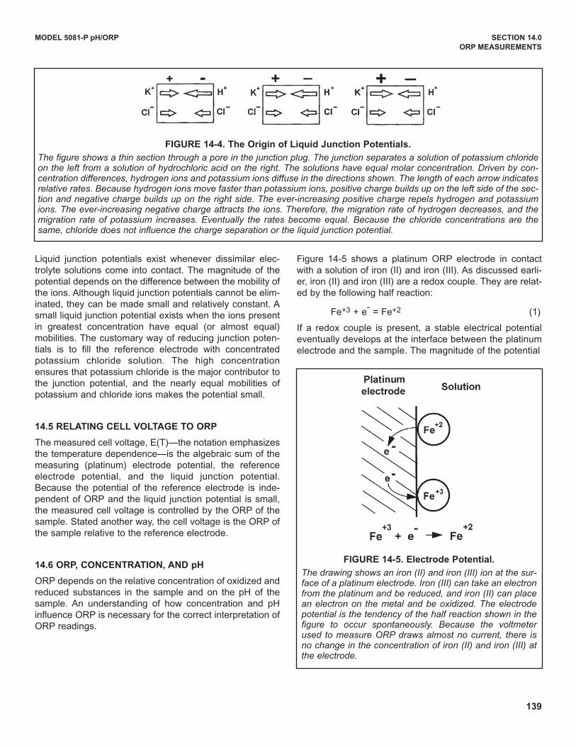
139
Liquid junction potentials exist whenever dissimilar elec-trolyte solutions come into contact. The magnitude of thepotential depends on the difference between the mobility ofthe ions. Although liquid junction potentials cannot be elim-inated, they can be made small and relatively constant. Asmall liquid junction potential exists when the ions presentin greatest concentration have equal (or almost equal)mobilities. The customary way of reducing junction poten-tials is to fill the reference electrode with concentratedpotassium chloride solution. The high concentrationensures that potassium chloride is the major contributor tothe junction potential, and the nearly equal mobilities ofpotassium and chloride ions makes the potential small.
14.5 RELATING CELL vOLTAGE TO ORP
The measured cell voltage, E(T)—the notation emphasizesthe temperature dependence—is the algebraic sum of themeasuring (platinum) electrode potential, the referenceelectrode potential, and the liquid junction potential.Because the potential of the reference electrode is inde-pendent of ORP and the liquid junction potential is small,the measured cell voltage is controlled by the ORP of thesample. Stated another way, the cell voltage is the ORP ofthe sample relative to the reference electrode.
14.6 ORP, CONCENTRATION, AND pH
ORP depends on the relative concentration of oxidized andreduced substances in the sample and on the pH of thesample. An understanding of how concentration and pHinfluence ORP is necessary for the correct interpretation ofORP readings.
Figure 14-5 shows a platinum ORP electrode in contactwith a solution of iron (II) and iron (III). As discussed earli-er, iron (II) and iron (III) are a redox couple. They are relat-ed by the following half reaction:
Fe+3 + e- = Fe+2 (1)
If a redox couple is present, a stable electrical potentialeventually develops at the interface between the platinumelectrode and the sample. The magnitude of the potential
MODEL 5081-P pH/ORP SECTION 14.0
ORP MEASUREMENTS
FIGURE 14-4. The Origin of Liquid Junction Potentials.
The figure shows a thin section through a pore in the junction plug. The junction separates a solution of potassium chlorideon the left from a solution of hydrochloric acid on the right. The solutions have equal molar concentration. Driven by con-centration differences, hydrogen ions and potassium ions diffuse in the directions shown. The length of each arrow indicatesrelative rates. Because hydrogen ions move faster than potassium ions, positive charge builds up on the left side of the sec-tion and negative charge builds up on the right side. The ever-increasing positive charge repels hydrogen and potassiumions. The ever-increasing negative charge attracts the ions. Therefore, the migration rate of hydrogen decreases, and themigration rate of potassium increases. Eventually the rates become equal. Because the chloride concentrations are thesame, chloride does not influence the charge separation or the liquid junction potential.
FIGURE 14-5. Electrode Potential.
The drawing shows an iron (II) and iron (III) ion at the sur-face of a platinum electrode. Iron (III) can take an electronfrom the platinum and be reduced, and iron (II) can placean electron on the metal and be oxidized. The electrodepotential is the tendency of the half reaction shown in thefigure to occur spontaneously. Because the voltmeterused to measure ORP draws almost no current, there isno change in the concentration of iron (II) and iron (III) atthe electrode.
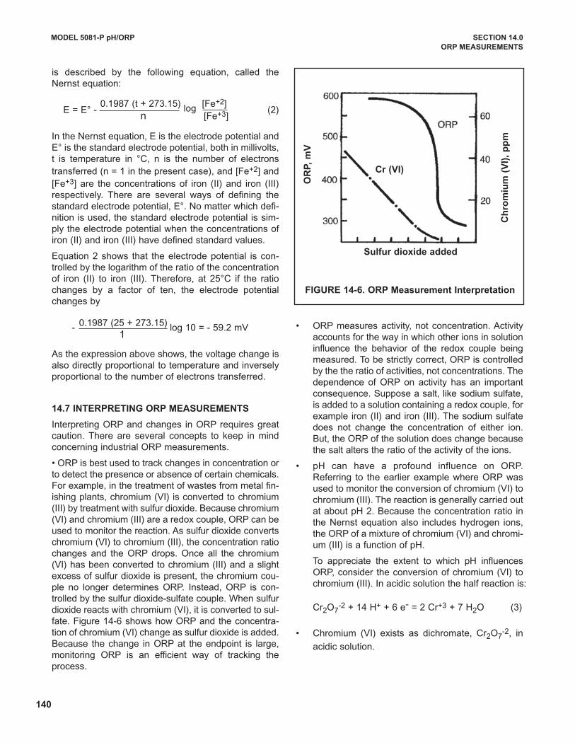
140
is described by the following equation, called theNernst equation:
E = E° - (2)
In the Nernst equation, E is the electrode potential andE° is the standard electrode potential, both in millivolts,t is temperature in °C, n is the number of electronstransferred (n = 1 in the present case), and [Fe+2] and[Fe+3] are the concentrations of iron (II) and iron (III)respectively. There are several ways of defining thestandard electrode potential, E°. No matter which defi-nition is used, the standard electrode potential is sim-ply the electrode potential when the concentrations ofiron (II) and iron (III) have defined standard values.
Equation 2 shows that the electrode potential is con-trolled by the logarithm of the ratio of the concentrationof iron (II) to iron (III). Therefore, at 25°C if the ratiochanges by a factor of ten, the electrode potentialchanges by
- log 10 = - 59.2 mV
As the expression above shows, the voltage change isalso directly proportional to temperature and inverselyproportional to the number of electrons transferred.
14.7 INTERPRETING ORP MEASUREMENTS
Interpreting ORP and changes in ORP requires greatcaution. There are several concepts to keep in mindconcerning industrial ORP measurements.
• ORP is best used to track changes in concentration orto detect the presence or absence of certain chemicals.For example, in the treatment of wastes from metal fin-ishing plants, chromium (VI) is converted to chromium(III) by treatment with sulfur dioxide. Because chromium(VI) and chromium (III) are a redox couple, ORP can beused to monitor the reaction. As sulfur dioxide convertschromium (VI) to chromium (III), the concentration ratiochanges and the ORP drops. Once all the chromium(VI) has been converted to chromium (III) and a slightexcess of sulfur dioxide is present, the chromium cou-ple no longer determines ORP. Instead, ORP is con-trolled by the sulfur dioxide-sulfate couple. When sulfurdioxide reacts with chromium (VI), it is converted to sul-fate. Figure 14-6 shows how ORP and the concentra-tion of chromium (VI) change as sulfur dioxide is added.Because the change in ORP at the endpoint is large,monitoring ORP is an efficient way of tracking theprocess.
• ORP measures activity, not concentration. Activityaccounts for the way in which other ions in solutioninfluence the behavior of the redox couple beingmeasured. To be strictly correct, ORP is controlledby the the ratio of activities, not concentrations. Thedependence of ORP on activity has an importantconsequence. Suppose a salt, like sodium sulfate,is added to a solution containing a redox couple, forexample iron (II) and iron (III). The sodium sulfatedoes not change the concentration of either ion.But, the ORP of the solution does change becausethe salt alters the ratio of the activity of the ions.
• pH can have a profound influence on ORP.Referring to the earlier example where ORP wasused to monitor the conversion of chromium (VI) tochromium (III). The reaction is generally carried outat about pH 2. Because the concentration ratio inthe Nernst equation also includes hydrogen ions,the ORP of a mixture of chromium (VI) and chromi-um (III) is a function of pH.
To appreciate the extent to which pH influencesORP, consider the conversion of chromium (VI) tochromium (III). In acidic solution the half reaction is:
Cr2O7-2 + 14 H+ + 6 e- = 2 Cr+3 + 7 H2O (3)
• Chromium (VI) exists as dichromate, Cr2O7-2, in
acidic solution.
MODEL 5081-P pH/ORP SECTION 14.0
ORP MEASUREMENTS
FIGURE 14-6. ORP Measurement Interpretation
0.1987 (t + 273.15) log [Fe+2]n [Fe+3]
0.1987 (25 + 273.15)1
Sulfur dioxide added
Cr (vI)
OR
P,
mv
Ch
rom
ium
(v
I),
pp
m
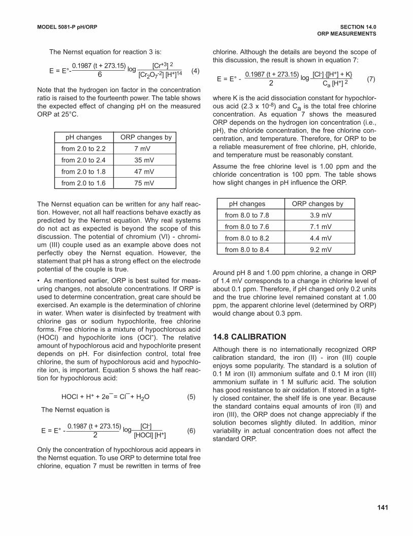
141
The Nernst equation for reaction 3 is:
E = E°- (4)
Note that the hydrogen ion factor in the concentrationratio is raised to the fourteenth power. The table showsthe expected effect of changing pH on the measuredORP at 25°C.
pH changes ORP changes by
from 2.0 to 2.2 7 mV
from 2.0 to 2.4 35 mV
from 2.0 to 1.8 47 mV
from 2.0 to 1.6 75 mV
The Nernst equation can be written for any half reac-tion. However, not all half reactions behave exactly aspredicted by the Nernst equation. Why real systemsdo not act as expected is beyond the scope of thisdiscussion. The potential of chromium (VI) - chromi-um (III) couple used as an example above does notperfectly obey the Nernst equation. However, thestatement that pH has a strong effect on the electrodepotential of the couple is true.
• As mentioned earlier, ORP is best suited for meas-uring changes, not absolute concentrations. If ORP isused to determine concentration, great care should beexercised. An example is the determination of chlorinein water. When water is disinfected by treatment withchlorine gas or sodium hypochlorite, free chlorineforms. Free chlorine is a mixture of hypochlorous acid(HOCl) and hypochlorite ions (OCl-). The relativeamount of hypochlorous acid and hypochlorite presentdepends on pH. For disinfection control, total freechlorine, the sum of hypochlorous acid and hypochlo-rite ion, is important. Equation 5 shows the half reac-tion for hypochlorous acid:
HOCl + H+ + 2e ̄= Cl ̄+ H2O (5)
The Nernst equation is
E = E° - (6)
Only the concentration of hypochlorous acid appears inthe Nernst equation. To use ORP to determine total freechlorine, equation 7 must be rewritten in terms of free
chlorine. Although the details are beyond the scope ofthis discussion, the result is shown in equation 7:
E = E° - (7)
where K is the acid dissociation constant for hypochlor-ous acid (2.3 x 10⁻⁸) and Ca is the total free chlorineconcentration. As equation 7 shows the measuredORP depends on the hydrogen ion concentration (i.e.,pH), the chloride concentration, the free chlorine con-centration, and temperature. Therefore, for ORP to bea reliable measurement of free chlorine, pH, chloride,and temperature must be reasonably constant.
Assume the free chlorine level is 1.00 ppm and thechloride concentration is 100 ppm. The table showshow slight changes in pH influence the ORP.
pH changes ORP changes by
from 8.0 to 7.8 3.9 mV
from 8.0 to 7.6 7.1 mV
from 8.0 to 8.2 4.4 mV
from 8.0 to 8.4 9.2 mV
Around pH 8 and 1.00 ppm chlorine, a change in ORPof 1.4 mV corresponds to a change in chlorine level ofabout 0.1 ppm. Therefore, if pH changed only 0.2 unitsand the true chlorine level remained constant at 1.00ppm, the apparent chlorine level (determined by ORP)would change about 0.3 ppm.
14.8 CALIBRATION
Although there is no internationally recognized ORPcalibration standard, the iron (II) - iron (III) coupleenjoys some popularity. The standard is a solution of0.1 M iron (II) ammonium sulfate and 0.1 M iron (III)ammonium sulfate in 1 M sulfuric acid. The solutionhas good resistance to air oxidation. If stored in a tight-ly closed container, the shelf life is one year. Becausethe standard contains equal amounts of iron (II) andiron (III), the ORP does not change appreciably if thesolution becomes slightly diluted. In addition, minorvariability in actual concentration does not affect thestandard ORP.
MODEL 5081-P pH/ORP SECTION 14.0
ORP MEASUREMENTS
0.1987 (t + 273.15) log [Cr+3] 2
6 [Cr2O7-2] [H+]14
0.1987 (t + 273.15) log [Cl-] 2 [HOCl] [H+]
0.1987 (t + 273.15) log [Cl-] {[H+] + K}2 Ca [H+] 2
142
MODEL 5081-P pH/ORP SECTION 14.0
ORP MEASUREMENTS
The ORP of the iron (II) - iron (III) standard when meas-ured with a platinum electrode against a saturated sil-ver-silver chloride reference is 476 ± 20 mV at 25°C.The range of values is caused primarily by the high andvariable liquid junction potential generated in solutionscontaining high acid concentrations.
Quinhydrone - hydroquinone ORP standards are alsoused. They are prepared by dissolving excess quinhy-drone in either pH 4.00 or pH 6.86 buffer. The ORP ofthe standards at a platinum electrode against a silver -silver chloride reference has been measured at 20°C,25°C, and 30°C.
Temperature ORP in ORP in pH 4.00 buffer pH 6.86 buffer
20°C 268 mV 92 mV
25°C 263 mV 86 mV
30°C 258 mV 79 mV
There are two disadvantages to using quinhydronestandards. First, the shelf life is only about eight hours,so fresh standard must be prepared daily. Second,hydroquinone is highly toxic, so preparing, handling,and disposing of the standards requires care.
unlike pH calibrations, which are generally done usingtwo calibration buffers, ORP calibrations are almostalways single point calibrations.
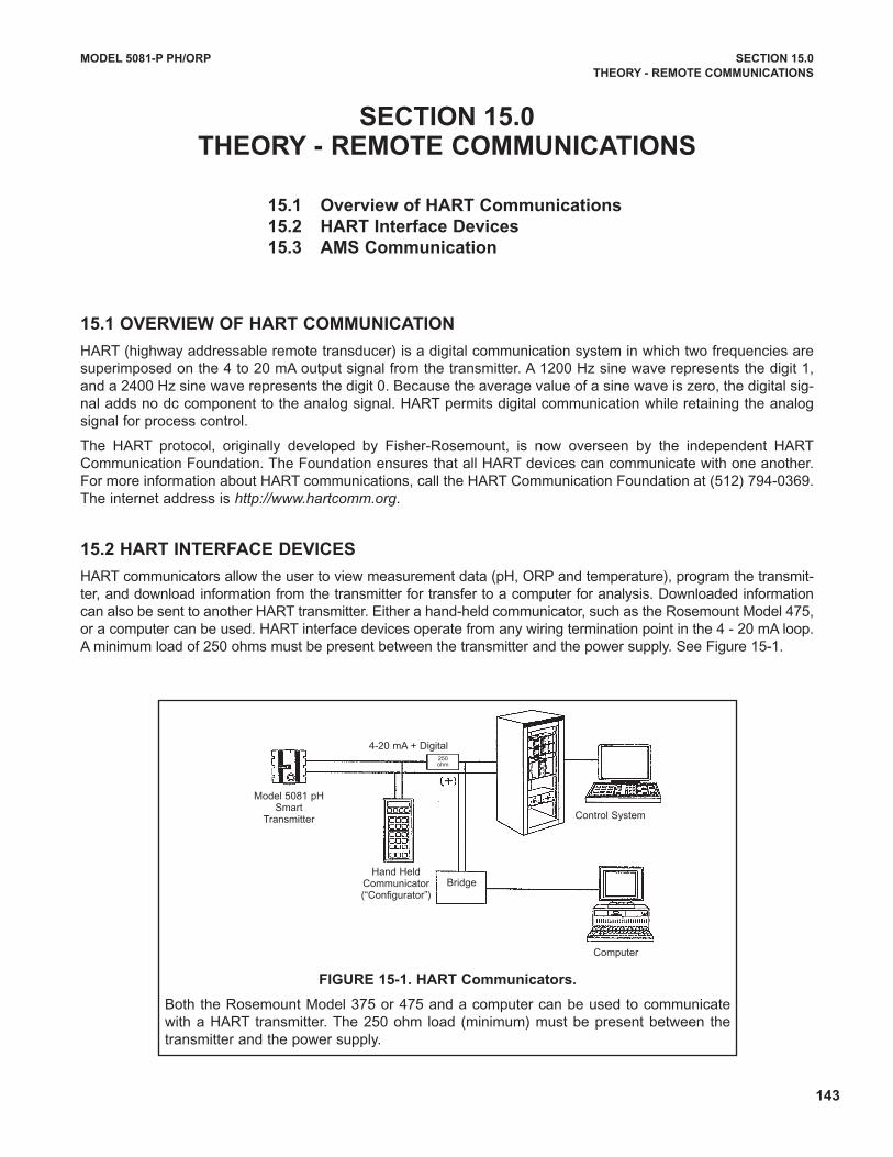
15.1 OvERvIEw OF HART COMMUNICATION
HART (highway addressable remote transducer) is a digital communication system in which two frequencies aresuperimposed on the 4 to 20 mA output signal from the transmitter. A 1200 Hz sine wave represents the digit 1,and a 2400 Hz sine wave represents the digit 0. Because the average value of a sine wave is zero, the digital sig-nal adds no dc component to the analog signal. HART permits digital communication while retaining the analogsignal for process control.
The HART protocol, originally developed by Fisher-Rosemount, is now overseen by the independent HARTCommunication Foundation. The Foundation ensures that all HART devices can communicate with one another.For more information about HART communications, call the HART Communication Foundation at (512) 794-0369.The internet address is http://www.hartcomm.org.
15.2 HART INTERFACE DEvICES
HART communicators allow the user to view measurement data (pH, ORP and temperature), program the transmit-ter, and download information from the transmitter for transfer to a computer for analysis. downloaded informationcan also be sent to another HART transmitter. Either a hand-held communicator, such as the Rosemount Model 475,or a computer can be used. HART interface devices operate from any wiring termination point in the 4 - 20 mA loop.A minimum load of 250 ohms must be present between the transmitter and the power supply. See Figure 15-1.
MODEL 5081-P PH/ORP SECTION 15.0
THEORy - REMOTE COMMUNICATIONS
SECTION 15.0THEORy - REMOTE COMMUNICATIONS
15.1 Overview of HART Communications
15.2 HART Interface Devices
15.3 AMS Communication
4-20 mA + digital250 ohm
Control System
Computer
Model 5081 pH Smart
Transmitter
BridgeHand Held
Communicator(“Configurator”)
FIGURE 15-1. HART Communicators.
Both the Rosemount Model 375 or 475 and a computer can be used to communicatewith a HART transmitter. The 250 ohm load (minimum) must be present between thetransmitter and the power supply.
143
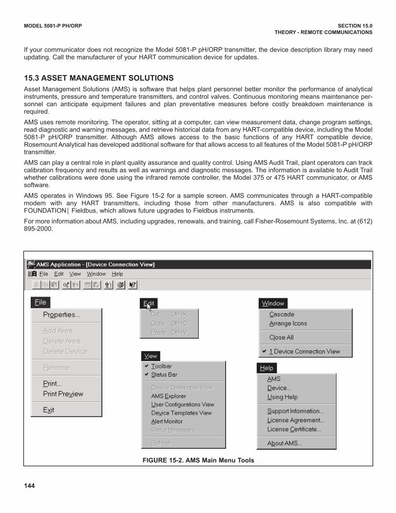
144
MODEL 5081-P PH/ORP SECTION 15.0
THEORy - REMOTE COMMUNICATIONS
If your communicator does not recognize the Model 5081-P pH/ORP transmitter, the device description library may needupdating. Call the manufacturer of your HART communication device for updates.
15.3 ASSET MANAGEMENT SOLUTIONS
Asset Management Solutions (AMS) is software that helps plant personnel better monitor the performance of analyticalinstruments, pressure and temperature transmitters, and control valves. Continuous monitoring means maintenance per-sonnel can anticipate equipment failures and plan preventative measures before costly breakdown maintenance isrequired.
AMS uses remote monitoring. The operator, sitting at a computer, can view measurement data, change program settings,read diagnostic and warning messages, and retrieve historical data from any HART-compatible device, including the Model5081-P pH/ORP transmitter. Although AMS allows access to the basic functions of any HART compatible device,Rosemount Analytical has developed additional software for that allows access to all features of the Model 5081-P pH/ORPtransmitter.
AMS can play a central role in plant quality assurance and quality control. using AMS Audit Trail, plant operators can trackcalibration frequency and results as well as warnings and diagnostic messages. The information is available to Audit Trailwhether calibrations were done using the infrared remote controller, the Model 375 or 475 HART communicator, or AMSsoftware.
AMS operates in Windows 95. See Figure 15-2 for a sample screen. AMS communicates through a HART-compatiblemodem with any HART transmitters, including those from other manufacturers. AMS is also compatible withFOuNdATIONÔ Fieldbus, which allows future upgrades to Fieldbus instruments.
For more information about AMS, including upgrades, renewals, and training, call Fisher-Rosemount Systems, Inc. at (612)895-2000.
FIGURE 15-2. AMS Main Menu Tools
MODEL 5081-P pH/ORP SECTION 16.0RETURN OF MATERIAL
SECTION 16.0
RETURN OF MATERIAL
16.1 GENERAL.
To expedite the repair and return of instruments, propercommunication between the customer and the factoryis important. Call 1-949-757-8500 for a ReturnMaterials Authorization (RMA) number.
16.2 wARRANTy REPAIR.
The following is the procedure for returning instru-ments still under warranty:
1. Call Rosemount Analytical for authorization.
2. To verify warranty, supply the factory sales ordernumber or the original purchase order number. Inthe case of individual parts or sub-assemblies, theserial number on the unit must be supplied.
3. Carefully package the materials and enclose your“Letter of Transmittal” (see Warranty). If possible,pack the materials in the same manner as theywere received.
4. Send the package prepaid to:
Emerson Process ManagementRosemount Analytical2400 Barranca ParkwayIrvine, CA 92606
Attn: Factory Repair
RMA No. ____________
Mark the package: Returned for Repair
Model No. ____
16.3 NON-wARRANTy REPAIR.
The following is the procedure for returning for repairinstruments that are no longer under warranty:
1. Call Rosemount Analytical for authorization.
2. Supply the purchase order number, and makesure to provide the name and telephone numberof the individual to be contacted should additionalinformation be needed.
3. do Steps 3 and 4 of Section 16.2.
NOTE
Consult the factory for additional informa-tion regarding service or repair.
145
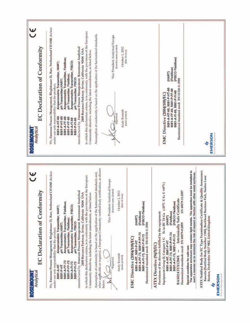
wARRANTy
Goods and part(s) (excluding consumables) manufactured by Seller are warranted to be free from defects in workman-ship and material under normal use and service for a period of twelve (12) months from the date of shipment by Seller.Consumables, pH electrodes, membranes, liquid junctions, electrolyte, O-rings, etc. are warranted to be free from defectsin workmanship and material under normal use and service for a period of ninety (90) days from date of shipment by Seller.Goods, part(s) and consumables proven by Seller to be defective in workmanship and / or material shall be replaced orrepaired, free of charge, F.O.B. Seller's factory provided that the goods, parts(s), or consumables are returned to Seller'sdesignated factory, transportation charges prepaid, within the twelve (12) month period of warranty in the case of goodsand part(s), and in the case of consumables, within the ninety (90) day period of warranty. This warranty shall be in effectfor replacement or repaired goods, part(s) and consumables for the remaining portion of the period of the twelve (12)month warranty in the case of goods and part(s) and the remaining portion of the ninety (90) day warranty in the case ofconsumables. A defect in goods, part(s) and consumables of the commercial unit shall not operate to condemn such com-mercial unit when such goods, parts(s) or consumables are capable of being renewed, repaired or replaced.
The Seller shall not be liable to the Buyer, or to any other person, for the loss or damage, directly or indirectly, arisingfrom the use of the equipment or goods, from breach of any warranty or from any other cause. All other warranties,expressed or implied are hereby excluded.
IN CONSIdERATION OF THE STATEd PuRCHASE PRICE OF THE GOOdS, SELLER GRANTS ONLY THE ABOVESTATEd EXPRESS WARRANTY. NO OTHER WARRANTIES ARE GRANTEd INCLudING, BuT NOT LIMITEd TO,EXPRESS ANd IMPLIEd WARRANTIES OF MERCHANTABILITY ANd FITNESS FOR A PARTICuLAR PuRPOSE.
RETURN OF MATERIAL
Material returned for repair, whether in or out of warranty, should be shipped prepaid to:
Emerson Process Management
Rosemount Analytical
2400 Barranca Parkway
Irvine, CA 92606
The shipping container should be marked:
Return for RepairModel _______________________________
The returned material should be accompanied by a letter of transmittal which should include the following information(make a copy of the "Return of Materials Request" found on the last page of the Manual and provide the following there-on):
1. Location type of service, and length of time of service of the device.2. description of the faulty operation of the device and the circumstances of the failure.3. Name and telephone number of the person to contact if there are questions about the returned material.4. Statement as to whether warranty or non-warranty service is requested.5. Complete shipping instructions for return of the material.
Adherence to these procedures will expedite handling of the returned material and will prevent unnecessary additionalcharges for inspection and testing to determine the problem with the device.
If the material is returned for out-of-warranty repairs, a purchase order for repairs should be enclosed.

LIQ-MAN-5081PRev. J
January 2015
Credit Cards for U.S. Purchases Only.
8
Emerson Process Management
2400 Barranca Parkway
Irvine, CA 92606 USA
Tel: (949) 757-8500
Fax: (949) 474-7250
rosemountanalytical.com
© Rosemount Analytical Inc. 2015
©2015 Rosemount Analytical, Inc. All rights reserved.
The Emerson logo is a trademark and service mark of Emerson Electric Co. Brand name is a markof one of the Emerson Process Management family of companies. All other marks are the propertyof their respective owners.
The contents of this publication are presented for information purposes only, and while effort hasbeen made to ensure their accuracy, they are not to be construed as warranties or guarantees,express or implied, regarding the products or services described herein or their use or applicability.All sales are governed by our terms and conditions, which are available on request. We reserve theright to modify or improve the designs or specifications of our products at any time without notice.
facebook.com/EmersonRosemountAnalytical
AnalyticExpert.com
twitter.com/RAIhome
youtube.com/user/RosemountAnalytical