Embed Size (px)
Citation preview

1
Manual
Series 100 Controller
InstallationMaintenanceRepairManual
Advantage Controls4700 Harold-Abitz Dr.Muskogee, OK 74403Phone: 800-743-7431Fax: 888-686-6212www.advantagecontrols.comemail: [email protected] 03/2021
2
Series 100 Controller ManualTable of Contents
Contents Page I. Introduction ........................................................................................ 2 II. ModelBuildingandGeneralSpecifications ....................................... 3
II. Installation ......................................................................................... 3 Power Wiring ..................................................................................... 3 Terminal Strip and Jumper Diagram .................................................. 4 Pump and Valve Relay Outputs ......................................................... 4 RO Pump Wiring ................................................................................ 4 Inlet and Flush Valve Wiring .............................................................. 4 TDS Cell Installation and Wiring ........................................................ 4 Switch Inputs ..................................................................................... 4 Pressure Fault Switch ........................................................................ 4 Pretreat Switch .................................................................................. 5
III. Front Panel Description ..................................................................... 6
IV. System Operation .............................................................................. 7 Display and Status Indicators ............................................................ 7 RO Start Delay .................................................................................. 7 Pressure Fault ................................................................................... 7 PF Auto Reset / PF Retry .................................................................. 8 Tank Full ............................................................................................ 8 Preatreat Lockout .............................................................................. 8 Membrane Flush ................................................................................ 8 Water Quality Display ........................................................................ 9 Water Quality Setpoint ....................................................................... 9 Calibration ......................................................................................... 9
V. Warranty and Factory Service Policies ............................................ 10
I. Introduction
The Advantage Controls Series 100 RO controller is a state of the art control system for commercial and industrial reverse osmosis systems. The S100 is a microprocessor-controlled system that can monitor pressure and level switches. A TDS monitor/controller with adjustable limit is an integral part of the unit. The S100 displays system status and sensor and switch input status using a status LED and a 3-digit LED display.

3
II. Model Building and General Specifications
Build a Model Model _ - _ _ _
Base Control SelectionS100=Inletsolenoid,flush,pressure switch, and TDSS101=Inletsolenoid,flush,pressure switch, and wiring harness kit
Controller Supply Voltage 1 = 120 VAC2 = 220 VAC3 = 120 VAC with UL labeling4 = 220 VAC with UL labeling
Permeate Conductivity Scale X = No conductivity A = 0-50 PPM B = 0-100 PPM C = 0-250 PPM D = 0-500 PPM E = 0-1,000 PPMJ = 0-50 uSK = 0-100 uSL = 0-250 uSM = 0-500 uSN = 0-1,000 uS
EnclosureA = 8.25”×5”×3” B = 8”×6”×4” polyX = 10”×8”×6” poly4 = 12”×10”×6” poly9=EnclosuredefinedinMotorControl model number, or no enclosure
III. Installation
MountingMounttheS100inaconvenientlocationontheROequipmentusingtheintegralmountingflanges.
Power WiringWARNING:Beforeapplyingpowertotheunit,verifythatthevoltagejumpersareconfiguredcorrectlyforthe voltage that will power the unit. The voltage jumpers are located below the transformer. For 120 VAC operation, there should be a wire jumper installed between J1 and J3 and a second wire jumper installed between J2 and J4. For 240 VAC operation, a single wire jumper should be installed between J3 and J4.
AC power for the unit is connected to terminal strip P1. Connect the ground wire of the AC power to P1-1 (GND). For AC power with a neutral and hot wire, the hot wire connects to P1-2 (L1) and the neutral wire connects to P1-3 (L2). For AC power with 2 hot wires, either wire can connect to L1 and L2.
Specifications
Power 120 VAC or 240 VAC - 15+10%, 50/60Hz
Enclosure 8.25”x5”x3” ABS plastic
Environment -22°F (-30°C) to 140°F (60°C), 0-95%RH, Non-condensing
Display 3-digit red LED
Front Panel Overlay with LED window, status LED, water quality LED, power and setpoint switches
Switch Inputs, Dry Contact:• Pressure fault• Pretreat lockout• Tank full
Relay Outputs• Inlet solenoid valve relay: 120/240 VAC 5
amp maximum• RO pump relay: 120/240 VAC 1HP, single
phase maximum• Flush solenoid valve relay: 120/240 VAC 5
amp maximumRelays supply same output voltage as board power (120 or 240 VAC) 20A maximum total load for all outputs.
!
4
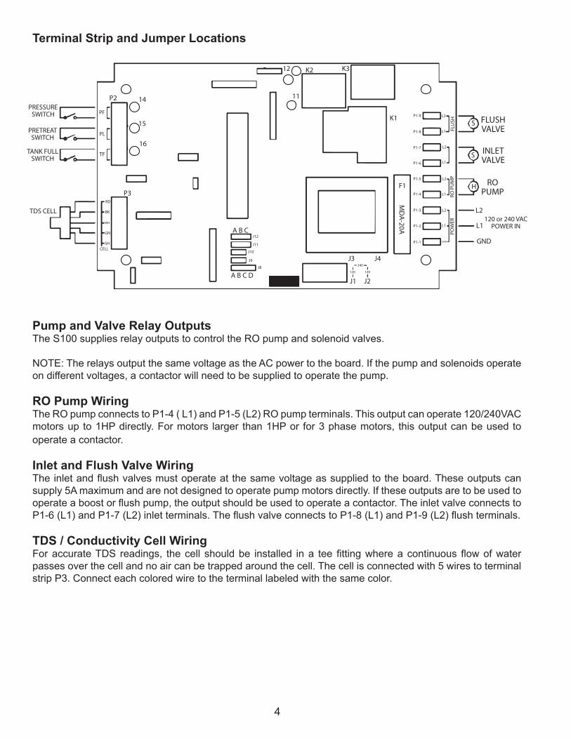
Terminal Strip and Jumper Locations
Pump and Valve Relay OutputsThe S100 supplies relay outputs to control the RO pump and solenoid valves.
NOTE: The relays output the same voltage as the AC power to the board. If the pump and solenoids operate ondifferentvoltages,acontactorwillneedtobesuppliedtooperatethepump.
RO Pump WiringThe RO pump connects to P1-4 ( L1) and P1-5 (L2) RO pump terminals. This output can operate 120/240VAC motors up to 1HP directly. For motors larger than 1HP or for 3 phase motors, this output can be used to operate a contactor.
Inlet and Flush Valve WiringTheinletandflushvalvesmustoperateatthesamevoltageassuppliedtotheboard.Theseoutputscansupply 5A maximum and are not designed to operate pump motors directly. If these outputs are to be used to operateaboostorflushpump,theoutputshouldbeusedtooperateacontactor.TheinletvalveconnectstoP1-6(L1)andP1-7(L2)inletterminals.TheflushvalveconnectstoP1-8(L1)andP1-9(L2)flushterminals.
TDS / Conductivity Cell WiringForaccurateTDS readings, thecell shouldbe installed ina teefittingwhereacontinuousflowofwaterpasses over the cell and no air can be trapped around the cell. The cell is connected with 5 wires to terminal strip P3. Connect each colored wire to the terminal labeled with the same color.
SK1
K3K212
11
J3
TDS CELL
PRESSURESWITCH
PRETREATSWITCH
TANK FULLSWITCH
RD
PF
P2
PL
TF
BK
GN
SHCELL
WH
P3
14
15
16
A B C
A B C DJ1
J4
J2
F1
MD
A-20A
S
H
L2
L1
GNDGND
FLUSHVALVEFL
USH
L2
L1
L2
L1
L2
L1
L2
P1-1
240
120120
P1-2
P1-3
P1-4
P1-5
P1-6
P1-7
P1-8
P1-9
L1
J12
J11
J10
J9
J8
RO P
UM
PPO
WER
INLETVALVE
ROPUMP
120 or 240 VACPOWER IN

5
Switch InputsSwitch inputs are connected to P2. The connections for these inputs are not polarity sensitive and can be connected to either terminal. The switch inputs should be dry contact closures only.
WARNING: Applying voltage to these terminals will damage the controller. The switches can be either normally open or normally closed, but all switches must be the same. If the controller is set for normally open switches, all switches must be open for the unit to run. If the controller is set for normally closed switches, all switches must be closed for the unit to run.
NOTE: J10 selects normally open or normally closed operation. When J10 is in the A position, the unit is configured fornormallyopenswitches.WhenJ10 is in theBposition, theunit isconfigured fornormallyclosed switches.
Pressure Fault SwitchOn systems where a low feed pressure shut down is required, a feed pressure switch can be connected to the pressure fault input of P2. If a high pump pressure shut down is required, a high pressure switch can be connected to this input. If both low feed pressure and high pump pressure shut down are required, both switches can be connected to this input. Both switches must be either normally open or normally closed to operate properly.
Pretreat SwitchIn systems with pretreatment, a pretreat lockout switch can be connected to the pretreat input of P2. This switch should operate when the pretreatment device is out of service.
NOTE: The output from the pretreatment device must be a dry contact and must not supply voltage.
Tank Full SwitchConnecting a tank full switch to the tank full input of P2 can cause the unit to shut down for a tank full condition. J9 selects a short or long tank full restart.
!
CAUTION1. There are live circuits inside the controller even when the power switch on the front panel is in
the OFF position. Never open the front panel without first disconnecting power from the outlet. Prewired controllers are supplied with an 8 foot, 18 AWG power cord with USA style plug. A #1 Phillips driver is required to open the front panel.
2. Low voltage signal wires (probes, flow switch, water meter, etc.) should never be run in conduit with high voltage (like 115VAC) wires.
3. Never attempt to land connections to the controller without first disconnecting power from the outlet.
4. Do not block access to disconnect power during mounting and installation.5. The controller should be connected to its own isolated circuit breaker, and for best
results, the ground should be a true earth ground, not shared. Any attempt to bypass the grounding will compromise the safety of users and property.
6. The electrical installation of the controller must be performed by trained personnel only and conform to all applicable National, State and Local codes.
7. Operation of this product in a manner not specified by the manufacturer may result in damage to equipment or persons.
8. Avoid mounting in locations that expose the controller to direct sunlight, vapors, vibration, liquid spills or extreme temperatures; less than 0°F (-17.8°C) or greater than 120°F (50°C). EMI(electromagnetic interference) from radio transmissions and electric motors can also cause damage or interference and should be avoided.
! !

6
IV. Front Panel Description
LED DISPLAY - Shows status of system and water quality.
STATUS LED - Shows operating status of unit.
WATER QUALITY LED - GREEN if OK, RED if above limit.
POWER KEY - Places controller in operating or standby mode.
SETPOINT KEY - Places display in mode to display current setpoint.
SP - Setpoint adjustment screw.
CAL - Calibration adjustment screw.
STATUS LCD/DISPLAYCONDITION DISPLAY STATUS LCDRO OFF OFFRO START DELAY ---RO OPERATING STEADY GREENTANK FULL FULTF RESTART FUL SLOW FLASH GREENPRETREAT PLFLUSH FLSPRESS FAULT PF FLASHING REDPF AUTO RESET PFPF RETRY PF STEADY RED
SETPOINT
POWER
STATUS WATER
SP
QUALITY
CAL
S100

7
V. System Operation
OperationThe S100 has 2 modes of operation, a standby mode and an operating mode. In the standby mode,theunitiseffectivelyoff.AlloutputsareturnedoffandthedisplayshowsOFF.Intheoperatingmode, the unit operates automatically. All inputs are monitored and the outputs are controlledaccordingly. Pressing the Power key will toggle the unit from standby to operate or from operate tostandby. If power is removed from the unit, when power is reapplied, the unit will restart in the modeit was in when power was removed.
Display and Status IndicatorsThe display is a 3 digit display. System operating status, the TDS reading and the TDS setpoint are shown on this display. A red/green LED indicates the system status in conjunction with the display.
CONDITION DISPLAY STATUS LEDRO OFF OFFRO START DELAY - - -RO OPERATING STEADY GREENTANK FULL FULTANK FULL RESTART FUL SLOW FLASH GREENPRETREAT LOCKOUT PLFLUSH FLSPRESSURE FAULT PF FLASHING REDPF AUTO RESET PFPF AUTO RETRY PF STEADY RED
RO Start DelayWhen the controller is placed in the operating mode or restarts from a shut down condition, the inlet valve will open and a 5 second time delay will start. During the delay, - - - will show on the water quality display. After this delay, the RO pump will start. The water quality display will now show the current water quality. The status lamp will show steady green.
Pressure FaultIf the pressure fault input is active for 2 seconds, a pressure fault condition will occur. This will cause the controllertoshutdown.PFwillshowonthewaterqualitydisplayandthestatuslampwillflashred.Toclearthe pressure fault, press the power key twice.

8
PF Auto Reset / PR RetryWith J8 in the A position, the power must be cycled using the Power key to clear a pressure fault shut down. A PF auto reset function is enabled by placing J8 in the B position. When a pressure fault occurs with the PF auto reset enabled, the controller will automatically reset after a 60 minute delay and the controller will start. If the pressure fault has cleared, the controller will continue to run. If the pressure fault condition is still active, the controller will again shut down for the pressure fault condition and the auto reset cycle will repeat. During theautoresetdelay,thewaterqualitydisplaywillshowPFandthestatuslampwillbeoff.
A PF retry function is enabled by placing J8 in the C position. When a pressure fault occurs with the PF retry enabled, the controller will shut down for 30 seconds and then attempt to restart. If the pressure fault is still active, the controller will shut down for 5 minutes and then attempt to restart. If the pressure fault is still active, the controller will shut down for 30 minutes and attempt to restart. If the pressure fault is still active, the controller will lockout for the pressure fault. During the retry delays, the water quality display will show PF and the status lamp will be a steady red. If during one of the retries, the controller is able to start and run continuously for 10 seconds, the retry function is reset. If a pressure fault occurs, the PF retry cycle will repeat from the beginning.
When J8 is in the D position, both the PF auto reset AND the PF retry functions are enabled. If a pressure fault condition occurs, the PF retry function will operate as described above. If the retry function locks out, the PF auto reset function will operate as described above. The PF retry and PF auto reset functions will continue
Tank FullIf the tank full input is active for 5 seconds, the controller will shut down for a tank full condition. The water quality display will show FUL. When the tank full condition clears, the unit will restart after the selected restart delay. The delay is selected with J9. With J9 in the A position, the restart delay is 2 seconds. With J9 in the B position, the restart delay is 15 minutes. Position A is normally used with tank level switches that have a large span.Duringtherestarttime,thestatuslampwillflashgreen.
Pretreat LockoutIf the pretreat lockout input is active for 2 seconds, the controller will shut down for a pretreat lockout condition. The water quality display will show PL. When the pretreat lockout condition clears, the unit will restart.
Membrane FlushAflushfunctioncanbeenabledusingJ11andJ12.Whenaflush is initiated, theflushvalvewilloperateandtheflushwilllast5minutes.Theflushcanoccurwhenatankfullconditionoccursorevery24hours,dependingonthejumpersettings.TheinletvalvecanbeopenorclosedandtheROpumpcanbeonoroff,depending on the jumper settings.
J11 J12 FLUSH TYPE INLET RO PUMPA A NONEA B TANK FULL OPEN ONA C TANK FULL CLOSED ONB A TANK FULL OPEN OFFB B TANK FULL CLOSED OFFB C 24 HOUR OPEN ONC A 24 HOUR CLOSED ONC B 24 HOUR OPEN OFFC C 24 HOUR CLOSED OFF

9
Water Quality DisplayThe water quality display shows the current water quality when the controller is operating normally and status messages when the controller is shut down. The water quality display is 0-999 PPM. If the water quality is above 999, the display will show ^ ^ ^. If the water quality is below the setpoint, the water quality lamp will be green. If the water quality is above the setpoint, the water quality lamp will be red.
Water Quality SetpointThe water quality setpoint can be adjusted from 0-999. If set to 999, the water quality lamp will always remain green. To set the water quality setpoint, press the Setpoint key. The display will alternate between the setpoint and SP. Use a small screwdriver to adjust the SP adjustment to the desired setpoint value. Press the Setpoint key to return the display to the water quality display.
CalibrationTo adjust the calibration of the water quality, measure the water with a meter calibrated to a known standard. Using a small screwdriver, adjust the CAL adjustment to get the correct reading on the display.

10
VI. Manufacturer’s Product Warranty
Advantage Controls warrants to the original purchaser that the products it manufactures will be free from defects in material and workmanship for a period of twelve months from the date of shipment on parts and ninety days on labor. Some non-Advantage manufactured resale items may have warranty periods less than twelve months. Advantage Controls’ obligation under this warranty is limited exclusively to the repair or replacementofanyproductthatAdvantagefindstobedefective.Itemsreturnedforwarrantyconsiderationmust have a return authorization number and be properly packaged, shipped prepaid and insured. This war-ranty is valid only when the products are properly installed, maintained and used for the purpose for which theyweredesigned.Misuse,neglect,damage,accident,improperrepair,ormodificationnotauthorizedinwriting by Advantage Controls will void this warranty.
Therearenowarranties,expressedorimplied,includingtheimpliedwarrantiesformerchantabilityorfitnessfor a particular purpose that extend beyond the limited warranty expressly stated above. Advantage Controls’ liability to any purchaser of its products, whether in contract or in tort, and whether arising out of warranties, representations, instructions, installations, or defects from any cause, will be limited exclusively to repairing or replacing the product or any part thereof under the conditions set out above.
30 Day Billing Memo Policy Advantage Controls maintains a unique factory exchange program to ensure uninterrupted service with mini-mum downtime. If your controller malfunctions, call 1 (918-686-6211 (international customers dial +1(918) 686-6211), and provide our technician with Model and Serial Number information. If they are unable to di-agnose and solve your problem over the phone, a fully warranted replacement unit will be shipped, usually within 48 hours, on a 30 Day Billing Memo. This service requires a purchase order and the replacement unit is billed to your regular account for payment. The replacement unit will be billed at current list price for that model less any applicable resale discount. Upon return of your old unit, credit will be issued to your account if the unit is in warranty. If the unit is out of warranty or the damage not covered, a partial credit will be applied based upon a prorated replacement price schedule dependent on the age of the unit. Any exchange covers only the controller or pump. Electrodes and other external accessories are not included.

11
- Notes -

12
Get the Advantage in Water Treatment EquipmentAdvantage Controls can give you the Advantage in products, knowledge and support on all of your water treatment equipment needs. Cooling Tower Controllers
Boiler Blow Down Controllers
Blow Down Valve Packages Solenoid Valves
Water Meters Chemical Metering Pumps
Corrosion Coupon Racks
Chemical Solution Tanks
Solid Feed Systems
Feed Timers
Filter Equipment
Glycol Feed Systems
Pre Fabricated Systems
Get the Advantage
5
4
3
2
1
0
9
8
7
6
BACK
HOME
HELP
ENTER
CANCEL
SET UPRUN
5
4
3
2
1
ENTER
HELP
5
4
3
CHANGE
RUN
SET UP0
9
8
2
1
7
6
HOME
BACK