Embed Size (px)
Citation preview
HEARING HELPER™ Personal FM SystemWireless FM Listening System
MANUAL AND USER GUIDE
MAN 072I
Models PFM 350, PFM 300, PFM 350E RCH, & PFM 300E RCHTransmitter Model PFM T32Optional Receiver Models PFM R32, R31
2
Contents Page
SYSTEM OVERVIEW 3
SYSTEM COMPONENTS 4
SAFETY INFORMATION 5
RECYCLING INSTRUCTIONS 5
OPERATING INSTRUCTIONS
PFM T32 TRANSMITTER 6
PFM R32 RECEIVER 9
PFM R31 RECEIVER 10
BATTERY INFORMATION
BATTERY INSTALLATION 13
RECHARGEABLE AND NON-RECHARGEABLE BATTERIES 13
USING OPTIONAL CHG 200 BATTERY CHARGER 14
USING YOUR PERSONAL FM SYSTEM WITH A HEARING AID 15
APPLICATIONS FOR VARIOUS HEARING LOSS LEVELS 15
IN CASE OF DIFFICULTY 16
WARRANTY 17
SYSTEM SPECIFICATIONS 18
ACOUSTIC SPECIFICATIONS 19
HEARING HELPER™ PERSONAL FM SYSTEM
MODELS PFM 350, PFM 300, PFM 350E RCH, PFM 300E RCHINSTALLATION GUIDE & USER MANUAL
3
Thank you for purchasing the Hearing Helper™ Personal FM System from Williams Sound Corp.Anyone needing auditory assistance to overcome background noise, reverberation, or distance fromthe sound source can benefit from the Personal FM System.
Your PFM System has two principal parts: the Transmitter and the Receiver. Much like a miniatureradio station, the Transmitter and microphone pick up the sounds you want to hear and broadcastthem over an FM radio signal. The receiver and earphone are used to pick up the broadcast up to 100feet away.
To avoid difficulties, please read through these instructions as you begin to use the system. Thensave them for questions that arise as you continue to use your Williams Sound Personal FM System.
If you have problems with the PFM system, don’t hesitate to call us toll-free at 1-800-843-3544.
SYSTEM OVERVIEW
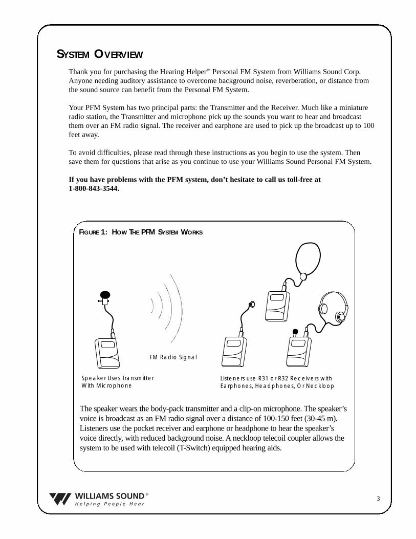
Speaker Uses TransmitterWith Microphone
FM Radio Signal
Listeners use R31 or R32 Receivers with Earphones, Headphones, Or Neckloop
The speaker wears the body-pack transmitter and a clip-on microphone. The speaker’svoice is broadcast as an FM radio signal over a distance of 100-150 feet (30-45 m).Listeners use the pocket receiver and earphone or headphone to hear the speaker’svoice directly, with reduced background noise. A neckloop telecoil coupler allows thesystem to be used with telecoil (T-Switch) equipped hearing aids.
FIGURE 1: HOW THE PFM SYSTEM WORKS
4
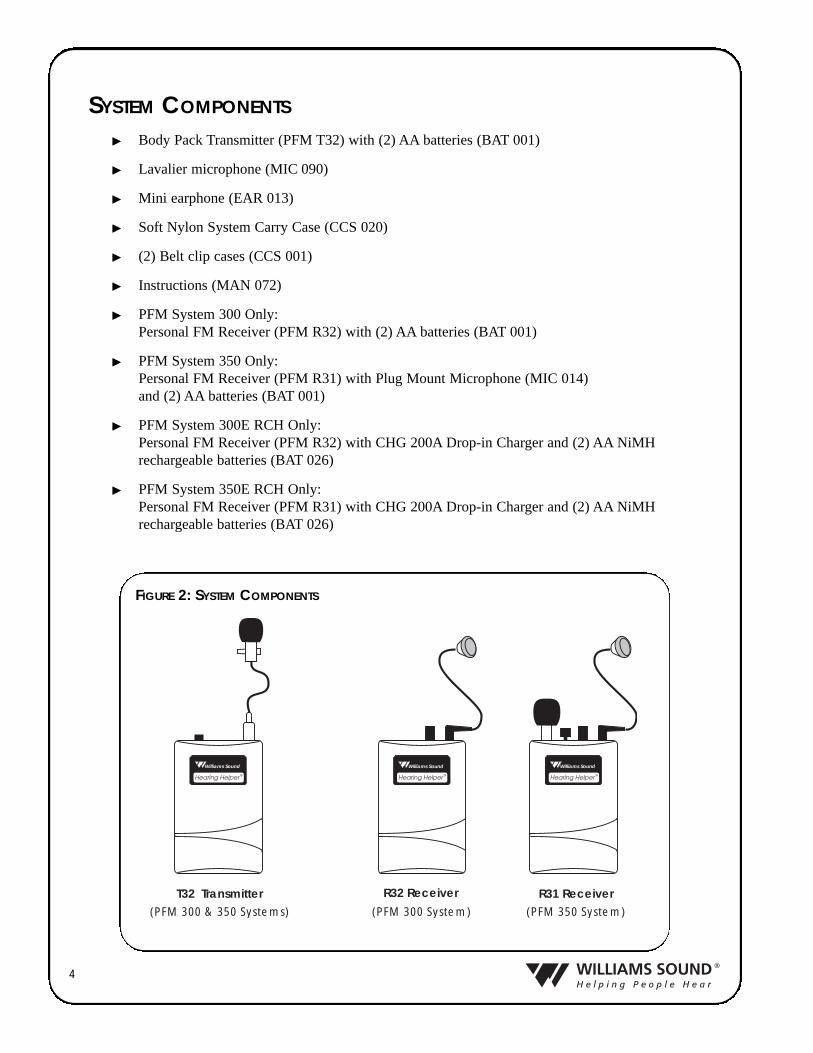
� Body Pack Transmitter (PFM T32) with (2) AA batteries (BAT 001)
� Lavalier microphone (MIC 090)
� Mini earphone (EAR 013)
� Soft Nylon System Carry Case (CCS 020)
� (2) Belt clip cases (CCS 001)
� Instructions (MAN 072)
� PFM System 300 Only:Personal FM Receiver (PFM R32) with (2) AA batteries (BAT 001)
� PFM System 350 Only:Personal FM Receiver (PFM R31) with Plug Mount Microphone (MIC 014) and (2) AA batteries (BAT 001)
� PFM System 300E RCH Only:Personal FM Receiver (PFM R32) with CHG 200A Drop-in Charger and (2) AA NiMHrechargeable batteries (BAT 026)
� PFM System 350E RCH Only:Personal FM Receiver (PFM R31) with CHG 200A Drop-in Charger and (2) AA NiMHrechargeable batteries (BAT 026)
SYSTEM COMPONENTS
R32 Receiver(PFM 300 System)
Williams Sound
Hearing Helper ®
Williams Sound
Hearing Helper ®
T32 Transmitter R31 Receiver(PFM 350 System)(PFM 300 & 350 Systems)
Williams Sound
Hearing Helper ®
Williams Sound
Hearing Helper ®
Williams Sound
Hearing Helper ®
Williams Sound
Hearing Helper ®
FIGURE 2: SYSTEM COMPONENTS
5
CAUTION!
CAUTION!
CAUTION!
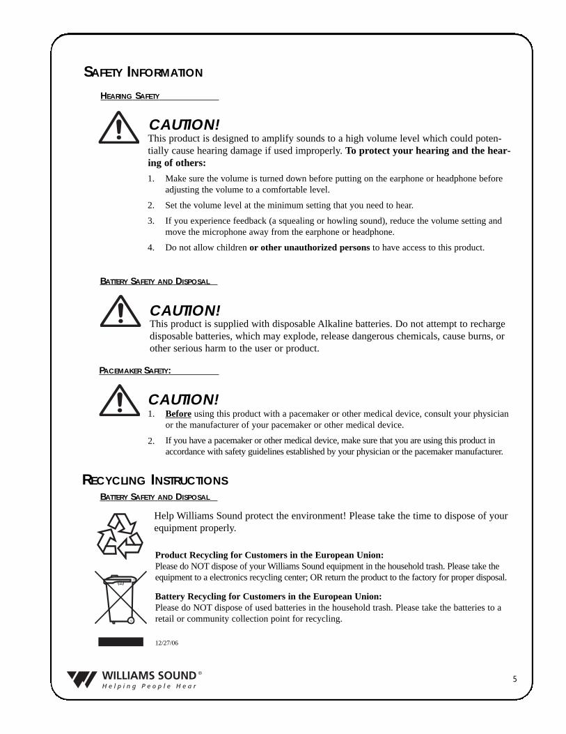
SAFETY INFORMATION
HEARING SAFETY
This product is designed to amplify sounds to a high volume level which could poten-tially cause hearing damage if used improperly. To protect your hearing and the hear-ing of others:
Make sure the volume is turned down before putting on the earphone or headphone beforeadjusting the volume to a comfortable level.
Set the volume level at the minimum setting that you need to hear.
If you experience feedback (a squealing or howling sound), reduce the volume setting andmove the microphone away from the earphone or headphone.
Do not allow children or other unauthorized persons to have access to this product.
1.
2.
3.
4.
BATTERY SAFETY AND DISPOSAL
This product is supplied with disposable Alkaline batteries. Do not attempt to rechargedisposable batteries, which may explode, release dangerous chemicals, cause burns, orother serious harm to the user or product.
PACEMAKER SAFETY:
Before using this product with a pacemaker or other medical device, consult your physicianor the manufacturer of your pacemaker or other medical device.
If you have a pacemaker or other medical device, make sure that you are using this product inaccordance with safety guidelines established by your physician or the pacemaker manufacturer.
1.
2.
BATTERY SAFETY AND DISPOSAL
Help Williams Sound protect the environment! Please take the time to dispose of yourequipment properly.
Product Recycling for Customers in the European Union:Please do NOT dispose of your Williams Sound equipment in the household trash. Please take theequipment to a electronics recycling center; OR return the product to the factory for proper disposal.
Battery Recycling for Customers in the European Union:Please do NOT dispose of used batteries in the household trash. Please take the batteries to aretail or community collection point for recycling.
12/27/06
RECYCLING INSTRUCTIONS
6
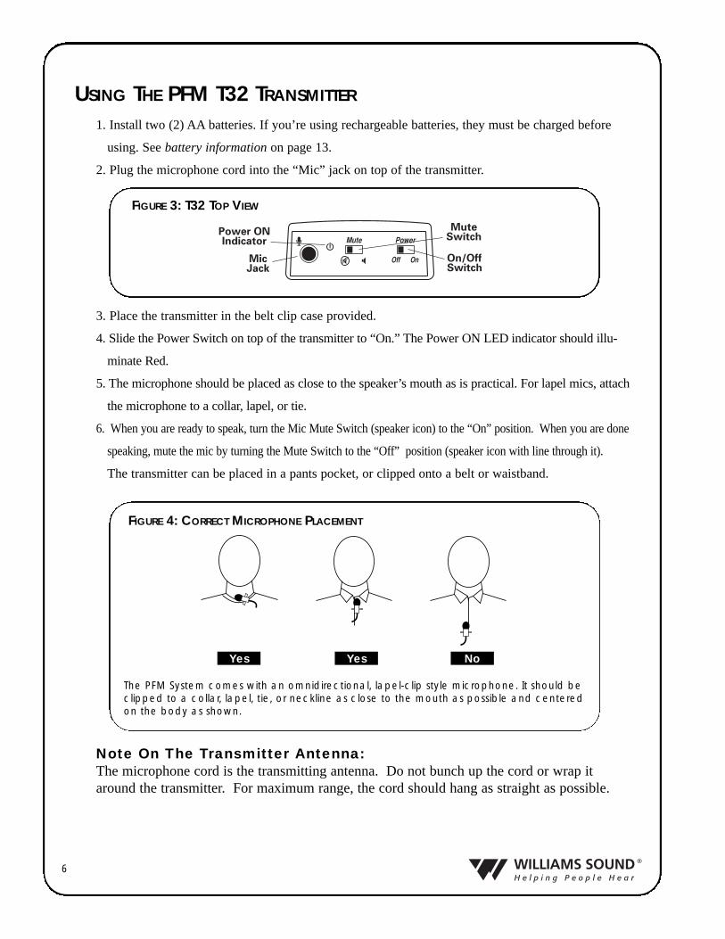
1. Install two (2) AA batteries. If you’re using rechargeable batteries, they must be charged before
using. See battery information on page 13.
2. Plug the microphone cord into the “Mic” jack on top of the transmitter.
3. Place the transmitter in the belt clip case provided.
4. Slide the Power Switch on top of the transmitter to “On.” The Power ON LED indicator should illu-
minate Red.
5. The microphone should be placed as close to the speaker’s mouth as is practical. For lapel mics, attach
the microphone to a collar, lapel, or tie.
6. When you are ready to speak, turn the Mic Mute Switch (speaker icon) to the “On” position. When you are done
speaking, mute the mic by turning the Mute Switch to the “Off” position (speaker icon with line through it).
The transmitter can be placed in a pants pocket, or clipped onto a belt or waistband.
Yes Yes No
The PFM System comes with an omnidirectional, lapel-clip style microphone. It should beclipped to a collar, lapel, tie, or neckline as close to the mouth as possible and centeredon the body as shown.
FIGURE 4: CORRECT MICROPHONE PLACEMENT
Note On The Transmitter Antenna:The microphone cord is the transmitting antenna. Do not bunch up the cord or wrap itaround the transmitter. For maximum range, the cord should hang as straight as possible.
USING THE PFM T32 TRANSMITTER
FIGURE 3: T32 TOP VIEW
7
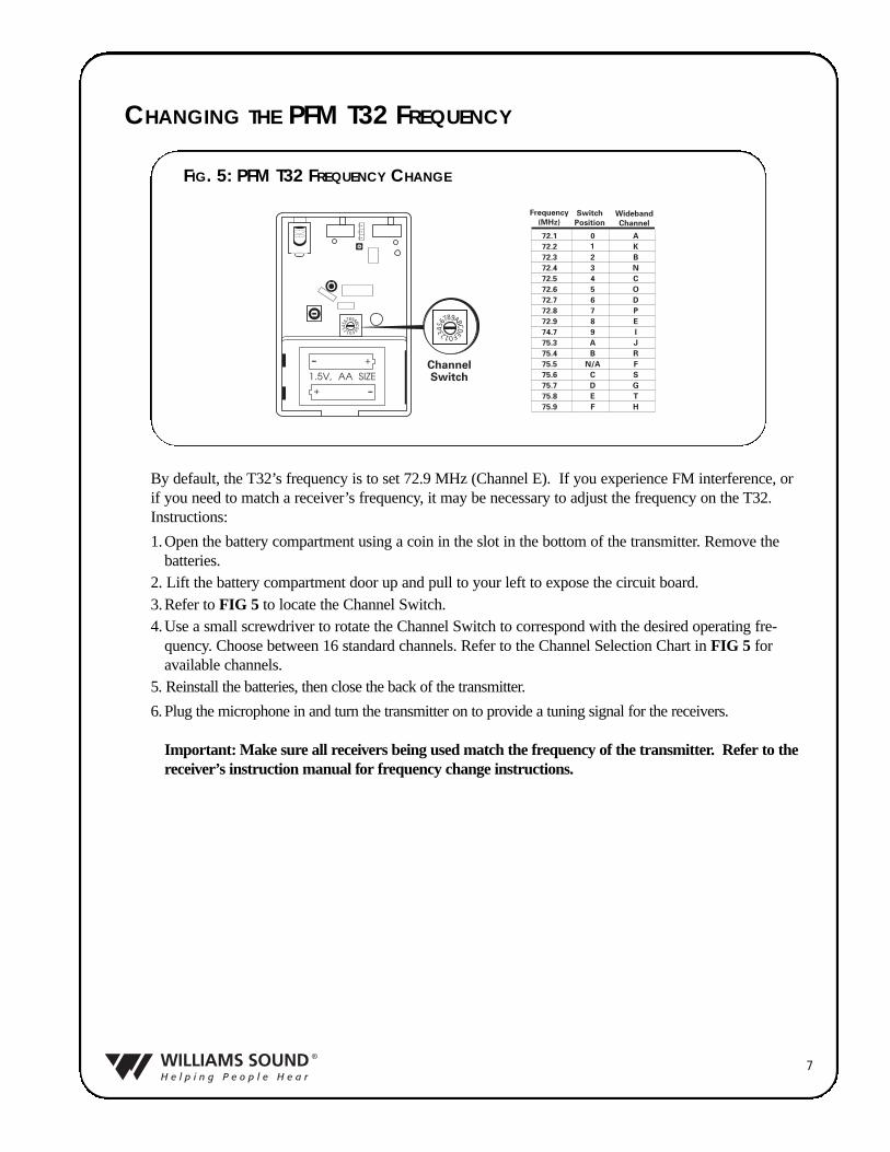
CHANGING THE PFM T32 FREQUENCY
FIG. 5: PFM T32 FREQUENCY CHANGE
By default, the T32’s frequency is to set 72.9 MHz (Channel E). If you experience FM interference, orif you need to match a receiver’s frequency, it may be necessary to adjust the frequency on the T32.Instructions:
1.Open the battery compartment using a coin in the slot in the bottom of the transmitter. Remove thebatteries.
2. Lift the battery compartment door up and pull to your left to expose the circuit board.3.Refer to FIG 5 to locate the Channel Switch.4.Use a small screwdriver to rotate the Channel Switch to correspond with the desired operating fre-
quency. Choose between 16 standard channels. Refer to the Channel Selection Chart in FIG 5 foravailable channels.
5. Reinstall the batteries, then close the back of the transmitter.
6. Plug the microphone in and turn the transmitter on to provide a tuning signal for the receivers.
Important: Make sure all receivers being used match the frequency of the transmitter. Refer to thereceiver’s instruction manual for frequency change instructions.
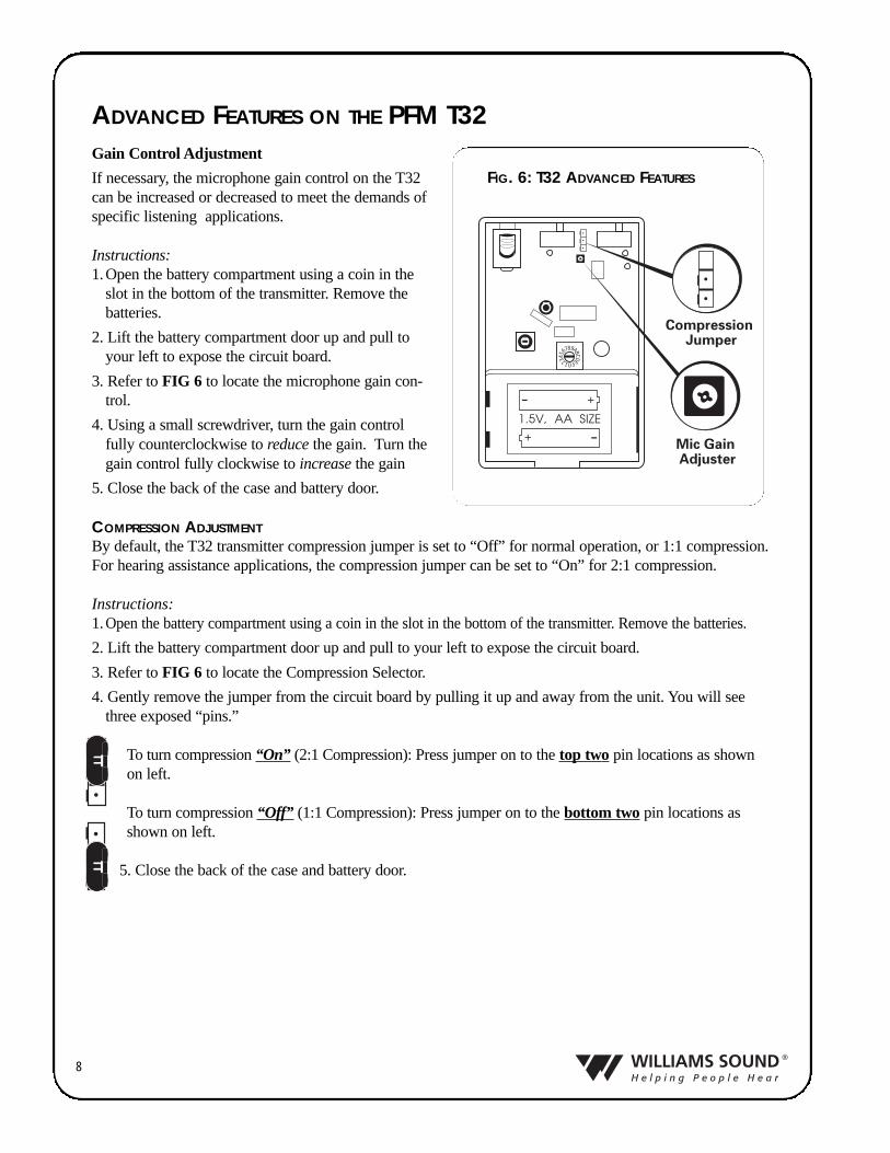
Gain Control Adjustment
If necessary, the microphone gain control on the T32can be increased or decreased to meet the demands ofspecific listening applications.
Instructions:1.Open the battery compartment using a coin in the
slot in the bottom of the transmitter. Remove thebatteries.
2. Lift the battery compartment door up and pull toyour left to expose the circuit board.
3. Refer to FIG 6 to locate the microphone gain con-trol.
4. Using a small screwdriver, turn the gain controlfully counterclockwise to reduce the gain. Turn thegain control fully clockwise to increase the gain
5. Close the back of the case and battery door.
COMPRESSION ADJUSTMENTBy default, the T32 transmitter compression jumper is set to “Off” for normal operation, or 1:1 compression.For hearing assistance applications, the compression jumper can be set to “On” for 2:1 compression.
Instructions:1. Open the battery compartment using a coin in the slot in the bottom of the transmitter. Remove the batteries.
2. Lift the battery compartment door up and pull to your left to expose the circuit board.
3. Refer to FIG 6 to locate the Compression Selector.
4. Gently remove the jumper from the circuit board by pulling it up and away from the unit. You will seethree exposed “pins.”
To turn compression “On” (2:1 Compression): Press jumper on to the top two pin locations as shownon left.
To turn compression “Off” (1:1 Compression): Press jumper on to the bottom two pin locations asshown on left.
5. Close the back of the case and battery door.
8
ADVANCED FEATURES ON THE PFM T32
FIG. 6: T32 ADVANCED FEATURES
9
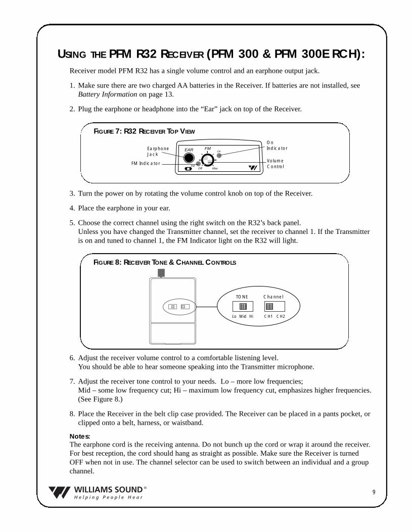
USING THE PFM R32 RECEIVER (PFM 300 & PFM 300E RCH):Receiver model PFM R32 has a single volume control and an earphone output jack.
1. Make sure there are two charged AA batteries in the Receiver. If batteries are not installed, seeBattery Information on page 13.
2. Plug the earphone or headphone into the “Ear” jack on top of the Receiver.
3. Turn the power on by rotating the volume control knob on top of the Receiver.
4. Place the earphone in your ear.
5. Choose the correct channel using the right switch on the R32’s back panel. Unless you have changed the Transmitter channel, set the receiver to channel 1. If the Transmitteris on and tuned to channel 1, the FM Indicator light on the R32 will light.
6. Adjust the receiver volume control to a comfortable listening level. You should be able to hear someone speaking into the Transmitter microphone.
7. Adjust the receiver tone control to your needs. Lo – more low frequencies; Mid – some low frequency cut; Hi – maximum low frequency cut, emphasizes higher frequencies.(See Figure 8.)
8. Place the Receiver in the belt clip case provided. The Receiver can be placed in a pants pocket, orclipped onto a belt, harness, or waistband.
Notes:The earphone cord is the receiving antenna. Do not bunch up the cord or wrap it around the receiver.For best reception, the cord should hang as straight as possible. Make sure the Receiver is turnedOFF when not in use. The channel selector can be used to switch between an individual and a groupchannel.
TONE Channel
Lo Mid Hi CH1 CH2
FIGURE 8: RECEIVER TONE & CHANNEL CONTROLS
EAR FM
FM
On
Off Max
EarphoneJack
OnIndicator
VolumeControl
FM Indicator
FIGURE 7: R32 RECEIVER TOP VIEW
10
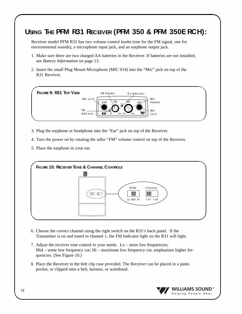
USING THE PFM R31 RECEIVER (PFM 350 & PFM 350E RCH):Receiver model PFM R31 has two volume control knobs (one for the FM signal, one forenvironmental sounds), a microphone input jack, and an earphone output jack.
1. Make sure there are two charged AA batteries in the Receiver. If batteries are not installed,see Battery Information on page 13.
2. Insert the small Plug Mount Microphone (MIC 014) into the “Mic” jack on top of the R31 Receiver.
3. Plug the earphone or headphone into the “Ear” jack on top of the Receiver.
4. Turn the power on by rotating the taller “FM” volume control on top of the Receiver.
5. Place the earphone in your ear.
6. Choose the correct channel using the right switch on the R31’s back panel. If theTransmitter is on and tuned to channel 1, the FM Indicator light on the R31 will light.
7. Adjust the receiver tone control to your needs. Lo – more low frequencies; Mid – some low frequency cut; Hi – maximum low frequency cut, emphasizes higher fre-quencies. (See Figure 10.)
8. Place the Receiver in the belt clip case provided. The Receiver can be placed in a pantspocket, or clipped onto a belt, harness, or waistband.
EAR MICFM Mic
FM
On
Min MaxOff Max
On Indicator
MicJack
FM Volume
MicVolume
Mic Jack
FMIndicator
FIGURE 9: R31 TOP VIEW
TONE Channel
Lo Mid Hi CH1 CH2
FIGURE 10: RECEIVER TONE & CHANNEL CONTROLS
11
Notes:The earphone cord is the receiving antenna. Do not bunch up the cord or wrap it around the receiver. Forbest reception, the cord should hang as straight as possible. Make sure the Receiver is turned OFF whennot in use. The channel selector can be used to switch between an individual and a group channel.
Adjusting The R31 Volume Controls1. Adjust the taller “FM” volume control to a comfortable listening level. You should be able to hear
someone speaking into the Transmitter microphone.
2. Now adjust the shorter “Mic” volume control until you can hear sounds picked up by the environ-mental microphone on top of the receiver.
3. Adjust the two volume controls for a comfortable mix of FM and environmental sounds.
You will normally want to have the FM signal louder than the environmental Mic signal toavoid picking up extra background noise. If no environmental sounds are desired, turn the“Mic” control fully to “Min”. If you want to hear nearby conversation or your own voice, turnthe “Mic” control up.
12
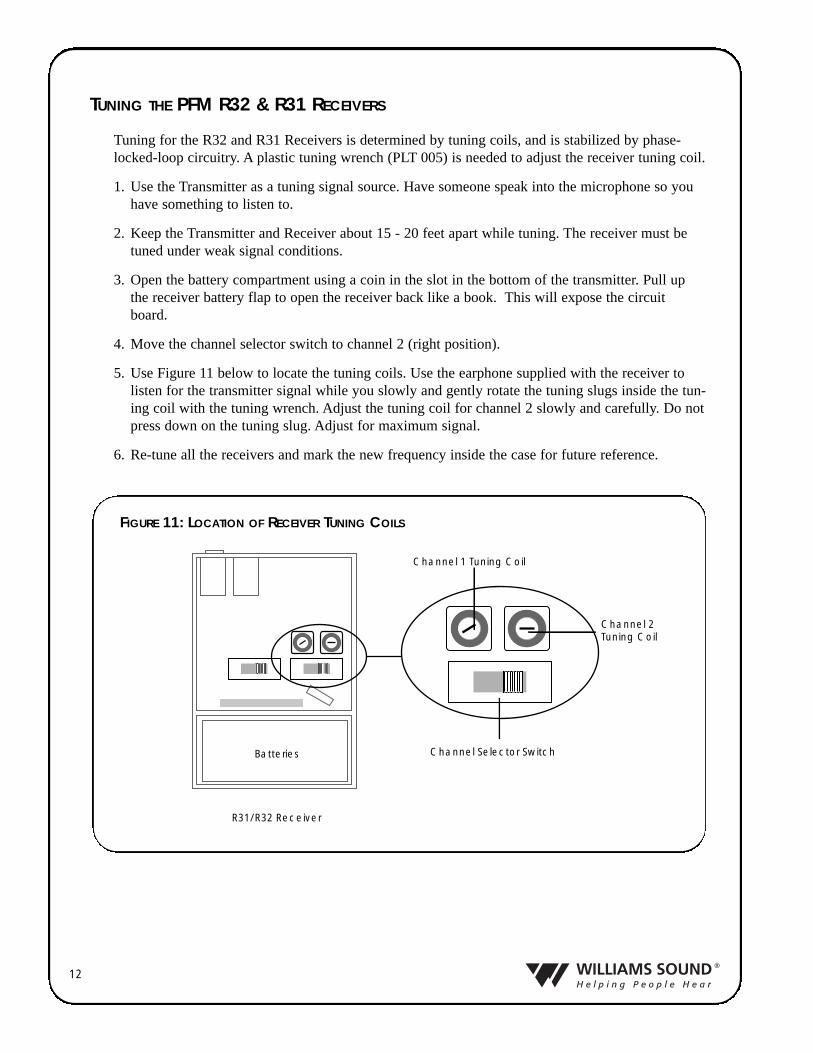
TUNING THE PFM R32 & R31 RECEIVERS
Tuning for the R32 and R31 Receivers is determined by tuning coils, and is stabilized by phase-locked-loop circuitry. A plastic tuning wrench (PLT 005) is needed to adjust the receiver tuning coil.
1. Use the Transmitter as a tuning signal source. Have someone speak into the microphone so youhave something to listen to.
2. Keep the Transmitter and Receiver about 15 - 20 feet apart while tuning. The receiver must betuned under weak signal conditions.
3. Open the battery compartment using a coin in the slot in the bottom of the transmitter. Pull upthe receiver battery flap to open the receiver back like a book. This will expose the circuitboard.
4. Move the channel selector switch to channel 2 (right position).
5. Use Figure 11 below to locate the tuning coils. Use the earphone supplied with the receiver tolisten for the transmitter signal while you slowly and gently rotate the tuning slugs inside the tun-ing coil with the tuning wrench. Adjust the tuning coil for channel 2 slowly and carefully. Do notpress down on the tuning slug. Adjust for maximum signal.
6. Re-tune all the receivers and mark the new frequency inside the case for future reference.
Batteries
R31/R32 Receiver
Channel 1 Tuning Coil
Channel 2Tuning Coil
Channel Selector Switch
FIGURE 11: LOCATION OF RECEIVER TUNING COILS
13
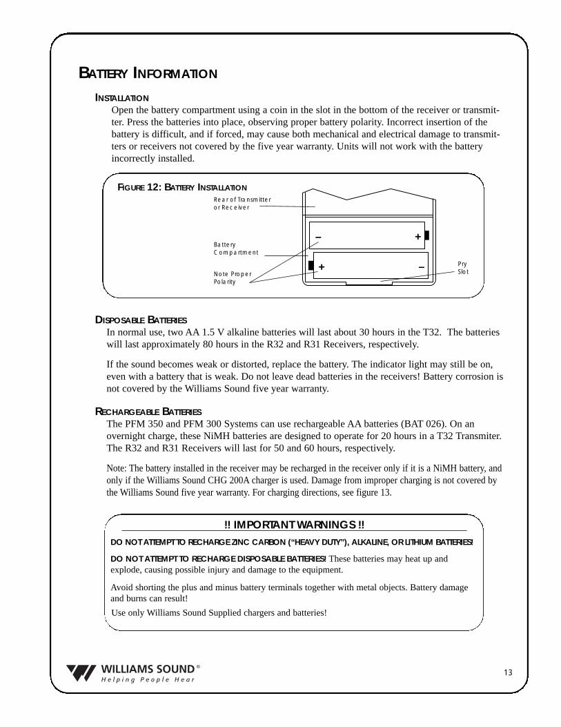
INSTALLATIONOpen the battery compartment using a coin in the slot in the bottom of the receiver or transmit-ter. Press the batteries into place, observing proper battery polarity. Incorrect insertion of thebattery is difficult, and if forced, may cause both mechanical and electrical damage to transmit-ters or receivers not covered by the five year warranty. Units will not work with the batteryincorrectly installed.
BATTERY INFORMATION
!! IMPORTANT WARNINGS !!DO NOT ATTEMPT TO RECHARGE ZINC CARBON (“HEAVY DUTY”), ALKALINE, OR LITHIUM BATTERIES!
DO NOT ATTEMPT TO RECHARGE DISPOSABLE BATTERIES! These batteries may heat up andexplode, causing possible injury and damage to the equipment.
Avoid shorting the plus and minus battery terminals together with metal objects. Battery damageand burns can result!
Use only Williams Sound Supplied chargers and batteries!
+–
+ –
Battery Compartment
Pry Slot
Rear of Transmitteror Receiver
Note Proper Polarity
DISPOSABLE BATTERIESIn normal use, two AA 1.5 V alkaline batteries will last about 30 hours in the T32. The batterieswill last approximately 80 hours in the R32 and R31 Receivers, respectively.
If the sound becomes weak or distorted, replace the battery. The indicator light may still be on,even with a battery that is weak. Do not leave dead batteries in the receivers! Battery corrosion isnot covered by the Williams Sound five year warranty.
RECHARGEABLE BATTERIESThe PFM 350 and PFM 300 Systems can use rechargeable AA batteries (BAT 026). On anovernight charge, these NiMH batteries are designed to operate for 20 hours in a T32 Transmiter.The R32 and R31 Receivers will last for 50 and 60 hours, respectively.
Note: The battery installed in the receiver may be recharged in the receiver only if it is a NiMH battery, andonly if the Williams Sound CHG 200A charger is used. Damage from improper charging is not covered bythe Williams Sound five year warranty. For charging directions, see figure 13.
FIGURE 12: BATTERY INSTALLATION
14
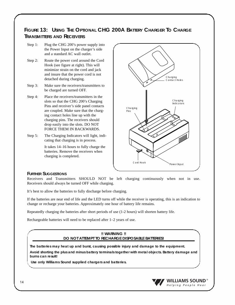
FIGURE 13: USING THE OPTIONAL CHG 200A BATTERY CHARGER TO CHARGE
TRANSMITTERS AND RECEIVERS
Step 1: Plug the CHG 200’s power supply intothe Power Input on the charger’s sideand a standard AC wall outlet.
Step 2: Route the power cord around the CordHook (see figure at right). This willminimize strain on the cord and jackand insure that the power cord is notdetached during charging.
Step 3: Make sure the receivers/transmitters tobe charged are turned OFF.
Step 4: Place the receivers/transmitters in theslots so that the CHG 200’s ChargingPins and receiver’s side panel contactsare coupled. Make sure that the charg-ing contact holes line up with thecharging pins. The receivers shoulddrop easily into the slots. DO NOTFORCE THEM IN BACKWARDS.
Step 5: The Charging Indicators will light, indi-cating that charging is in process.
It takes 14–16 hours to fully charge thebatteries. Remove the receivers whencharging is completed.
FURTHER SUGGESTIONSReceivers and Transmitters SHOULD NOT be left charging continuously when not in use. Receivers should always be turned OFF while charging.
It’s best to allow the batteries to fully discharge before charging.
If the batteries are near end of life and the LED turns off while the receiver is operating, this is an indication tochange or recharge your batteries. Approximately one hour of battery life remains.
Repeatedly charging the batteries after short periods of use (1-2 hours) will shorten battery life.
Rechargeable batteries will need to be replaced after 1–2 years of use.
Charging Indicators
ChargingPins
Cord HookPower Input
ChargingContact Holes
!! WARNING !!DO NOT ATTEMPT TO RECHARGE DISPOSABLE BATTERIES!
The batteries may heat up and burst, causing possible injury and damage to the equipment.
Avoid shorting the plus and minus battery terminals together with metal objects. Battery damage andburns can result!
Use only Williams Sound supplied chargers and batteries.
15
USING YOUR PERSONAL FM SYSTEM WITH A HEARING AID
If you have a hearing aid equipped with a Telecoil (T-Switch), you can use a Neckloop (NKL 003–children’s size, or NKL 001–adult’s size) to magnetically couple the signal from thePFM Receiver into your hearing aid.
The Neckloop plugs into the earphone jack of the receiver. Turn the switch to the “T” position onyour hearing aid and adjust the volume control on the receiver to a comfortable level. If you havetwo hearing aids with telecoils, the signal will couple into both hearing aids (when using a silhou-ette).
Direct Audio Input cords can be used with compatible hearing aids as well as with Cochlear ImplantProcessors. If your hearing aid has a direct audio input boot, you can obtain a cord from your hear-ing aid manufacturer to plug directly into the PFM receiver. The cord should have a 3.5 mm plug.
The Personal FM is designed to provide hearing assistance for anyone when background noise ordistance from the sound source make listening difficult. The microphone and transmitter are placedclose to the desired sound source to help minimize background noise and to effectively eliminatethe distance between the listener and the sound source. Because hearing ability varies, three cate-gories of amplification have been delineated:
NO HEARING LOSS – LOW AMPLIFICATIONAmong Low Amplification applications are classroom and similar uses. The PFM System can beused with headphones or earphones for Central Auditory Processing Disorders, LearningDisabilities, or Attention Deficit Disorders. The PFM System is used primarily to boost speechsounds above other background noises, making it easier for the listener to focus on what is beingsaid. The optional Rugged Headphone (HED 022–children’s size, and HED 021–adult’s size) arerecommended for this application. The EAR 013 Single Mini Earphone, EAR 008 SurroundEarphone, or EAR 014 Dual Mini Earphone can also be used.
MILD – MODERATE HEARING LOSSThese applications include the classroom, TV listening, car riding, and one-on-one conversations.The PFM System can be used with the Single or Dual Mini Earphone (EAR 013 or EAR 014)for moderate amplification fittings. The PFM System is also suitable for temporary mild hearingloss due to Otitis Media. The Rugged Headphones (HED 021) or Surround Earphone (EAR 022or EAR 008) are recommended since they do not enter the ear canal.
SEVERE – PROFOUND HEARING LOSSThese applications include the classroom, TV listening, car riding, and one-on-one conversations.For severe to profound hearing loss, the PERSONAL FM System should be used in conjunctionwith a hearing aid. A Neckloop can be used with hearing aids that have a telecoil. An adaptorcord can be used with hearing aids that have direct audio input
APPLICATIONS FOR VARIOUS HEARING LOSS LEVELS
16
IN CASE OF DIFFICULTY
If your Personal FM System is not working, check the following:
1. Read through the manual and user guide carefully to verify proper setup and installation of your system.
2. Make sure the batteries are fresh or completely charged and that the “plus” and “minus” termi-nals are installed correctly.
3. If the rechargeable batteries will only work for a short period of time (less than 1 hour) evenafter they are fully charged, they must be regenerated. Leave them in the receiver or transmitterwith the unit turned on, for 5 - 6 hours. Then turn receiver or transmitter off, place it in thecharger, and charge for 14 - 16 hours. This should restore normal battery life. Rechargeable bat-teries will gradually lose their capacity over time and should be replaced every year.
4. Make sure the microphone is plugged into the T32 Transmitter and the earphone is plugged intothe Receiver.
5. If you have the PFM System 350, make sure the R31 Receiver’s plug mount microphone ISNOT plugged into the Transmitter.
6. If you’re using the PFM System 350 with the PFM R31 Receiver, make sure that the earphonehas been plugged into the earphone jack and not into the R31 Receiver’s microphone jack.
7. Move the Transmitter and Receiver closer together. You may be out of range. When using thesystem indoors, it’s normal for the signal to momentarily disappear in certain locations. This iscalled a “drop-out.” Moving a few feet will restore the signal.
8. Make sure that the Transmitter and Receivers are tuned to the same channel. The units havestickers inside the back cover identifying the channel. Unless the Transmitter channel has beenchanged, set the Receiver to channel 1.
9. Do not try to use more than one Transmitter on the same channel in close proximity to eachother. MORE THAN ONE TRANSMITTER ON THE SAME CHANNEL WILL RESULT ININTERFERENCE IF THEY ARE CLOSE TOGETHER. Keep the systems 50 - 100 feet apartor use separate channels for each system used.
10. If you are still hearing interference on the Receivers, turn the Transmitter off and listen with areceiver. If you hear the interference with the Transmitter off, you need to change to a clearchannel. See the re-tuning instructions.
11. If problems remain, contact your dealer for further help. Or call Williams Sound toll-free at1-800-843-3544.
17
Limited WarrantyWilliams Sound products are engineered, designed, and manufactured under carefully controlled condi-tions to provide you with many years of reliable service. Williams Sound warrants the Hearing Helper®
Personal FM System against defects in materials and workmanship for FIVE (5) years. During the firstfive years from the purchase date, we will promptly repair or replace the Hearing Helper® Personal FMSystem.
Microphones, earphones, headphones, batteries, chargers, cables, carry cases, and all other accessoryproducts carry a 90-day warranty.
WILLIAMS SOUND HAS NO CONTROL OVER THE CONDITIONS UNDER WHICH THIS PROD-UCT IS USED. WILLIAMS SOUND, THEREFORE, DISCLAIMS ALL WARRANTIES NOT SETFORTH ABOVE, BOTH EXPRESS AND IMPLIED, WITH RESPECT TO THE Hearing Helper®
Personal FM System, INCLUDING BUT NOT LIMITED TO, ANY IMPLIED WARRANTY OF MER-CHANTABILITY OR FITNESS FOR A PARTICULAR PURPOSE. WILLIAMS SOUND SHALL NOTBE LIABLE TO ANY PERSON OR ENTITY FOR ANY MEDICAL EXPENSES OR ANY DIRECT,INCIDENTAL OR CONSEQUENTIAL DAMAGES CAUSED BY ANY USE, DEFECT, FAILURE ORMALFUNCTIONING OF THE PRODUCT, WHETHER A CLAIM FOR SUCH DAMAGES IS BASEDUPON WARRANTY, CONTRACT, TORT OR OTHERWISE, THE SOLE REMEDY FOR ANYDEFECT, FAILURE OR MALFUNCTION OF THE PRODUCTS REPLACEMENT OF THE PROD-UCT. NO PERSON HAS ANY AUTHORITY TO BIND WILLIAMS SOUND TO ANY REPRESENTA-TION OR WARRANTY WITH RESPECT TO THE HEARING HELPER® PERSONAL FM SYSTEM.UNAUTHORIZED REPAIRS OR MODIFICATIONS WILL VOID THE WARRANTY.
The exclusions and limitations set out above are not intended to, and should not be construed so as to con-travene mandatory provisions of applicable law. If any part or term of this Disclaimer of Warranty is heldto be illegal, unenforceable, or in conflict with applicable law by a court of competent jurisdiction, thevalidity of the remaining portions of this Disclaimer of Warranty shall not be affected, and all rights andobligations shall be construed and enforced as if this Limited Warranty did not contain the particular partor term held to be invalid.
If you experience difficulty with your system, call Toll-Free for customer Assistance:
1-800-843-3544 (U.S.A.) or +1 952 943 2252 (Outside the U.S.A.)
If it is necessary to return the system for service, your Customer Service Representative will give you aReturn Authorization Number (RA) and shipping instruction.
Pack the system carefully and send it to:
Williams Sound Corp.Attn: Repair Dept.10321 West 70th StreetEden Prairie, MN 55344 USA
Your warranty becomes effective the date you purchase your system. Your returned warranty card isour way of knowing when you warranty begins. Please take a moment to fill it out and mail theenclosed card. You may also register your product online: www.williamssound.com/registration.aspx.This information will help us serve you better in the future. Thank you!
18
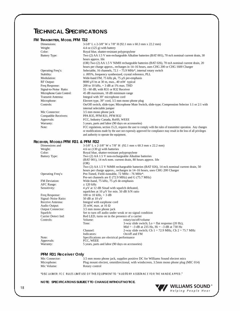
TECHNICAL SPECIFICATIONSFM TRANSMITTER, MODEL PFM T32
Dimensions: 3-5/8" L x 2-3/8" W x 7/8" H (92.1 mm x 60.3 mm x 22.2 mm) Weight: 4.4 oz (125 g) with batteryColor: Royal blue, shatter-resistant polypropyleneBattery Type: Two (2) AA 1.5 V non-rechargeable Alkaline batteries (BAT 001), 70 mA nominal current drain, 30
hours approx. life(OR) Two (2) AA 1.5 V NiMH rechargeable batteries (BAT 026), 70 mA nominal current drain, 20hours per charge approx., recharges in 14–16 hours, uses CHG 200 or CHG 1600 Charger
Operating Freq’s: Selectable, 16 channels, 72.1 – 75.9 MHz*, internal rotary switchStability: ± .005%, frequency synthesized, crystal reference, PLLModulation: Wide-band FM, 75 kHz pk, 75 µS pre-emphasisRF Output: 8000 µV/m at 30 m, max., 40 mW typicalFreq Response: 200 to 10 kHz, + 3 dB at 1% max. THDSignal-to-Noise Ratio: 55 - 60 dB, with R31 or R32 ReceiverMicrophone Gain Control: 45 dB maximum, 18 dB minimum rangeTransmit Antenna: Integral with 39" microphone cordMicrophone: Electret type, 39" cord, 3.5 mm mono phone plugControls: On/Off switch, slide-type; Microphone Mute Switch, slide-type; Compression Selector 1:1 or 2:1 with
internal selectable jumperMic Connector: 3.5 mm mono phone jackCompatible Receivers: PPA R35, PFM R31, PFM R32Approvals: FCC, Industry Canada, RoHS, WEEEWarranty: 5 years, parts and labor (90 days on accessories)Note: FCC regulations, section 15.21, requires the user to comply with the rules of transmitter operation. Any changes
or modifications made by the user not expressly approved for compliance may result in the loss of all privilegesand authority to operate the equipment.
RECEIVER, MODELS PFM R31 & PFM R32Dimensions and 3-5/8" L x 2-3/8" W x 7/8" H (92.1 mm x 60.3 mm x 22.2 mm) Weight: 4.6 oz (130 g) with batteriesColor: Royal blue, shatter-resistant polypropyleneBattery Type: Two (2) AA 1.5 V non-rechargeable Alkaline batteries
(BAT 001), 14 mA nom. current drain, 80 hours approx. life(OR)Two (2) AA 1.5 V NiMH rechargeable batteries (BAT 026), 14 mA nominal current drain, 50hours per charge approx., recharges in 14–16 hours, uses CHG 200 Charger
Operating Freq’s: Pre-Tuned, Field–tuneable, 72 MHz - 76 MHz*. Pre-set channels are E (72.9 MHz) and G (75.7 MHz)
FM Deviation: Wide-band, 75 kHz, 75 µS de-emphasisAFC Range: ± 120 kHzSensitivity: 4 µV at 12 dB Sinad with squelch defeated,
squelches at 10 µV for min. 50 dB S/N ratioFreq Response: 100 to 10 kHz, + 3 dBSignal–Noise Ratio: 50 dB at 10 uVReceive Antenna: Integral with earphone cordAudio Output: 35 mW, max. at 16 ΩOutput Connector: 3.5 mm mono phone jackSquelch: Set to turn off audio under weak or no signal conditionCarrier Detect Ind: Red LED, turns on in the presence of a carrier Controls: Volume: rotary/on/off/volume
Tone: 3-way slide switch; Lo = flat response (20 Hz), Mid = –3 dB at 235 Hz, Hi = –3 dB at 730 Hz
Channel: 2-way slide switch; Ch 1 = 72.9 MHz, Ch 2 = 75.7 MHzIndicators: On/off and FM
Note: Specifications are electrical performanceApprovals: FCC, WEEEWarranty: 5 years, parts and labor (90 days on accessories)
PFM R31 Receiver OnlyMic Connector: 3.5 mm mono phone jack, supplies positive DC for Williams Sound electret micsMicrophone: Plug mount electret, omnidirectional, with windscreen, 3.5mm mono phone plug (MIC 014)Mic Volume: Rotary control
*DISCLAIMER: FCC RULES LIMIT USE OF THIS EQUIPMENT TO “AUDITORY ASSISTANCE FOR THE HANDICAPPED.”
NOTE: SPECIFICATIONS SUBJECT TO CHANGE WITHOUT NOTICE.
19
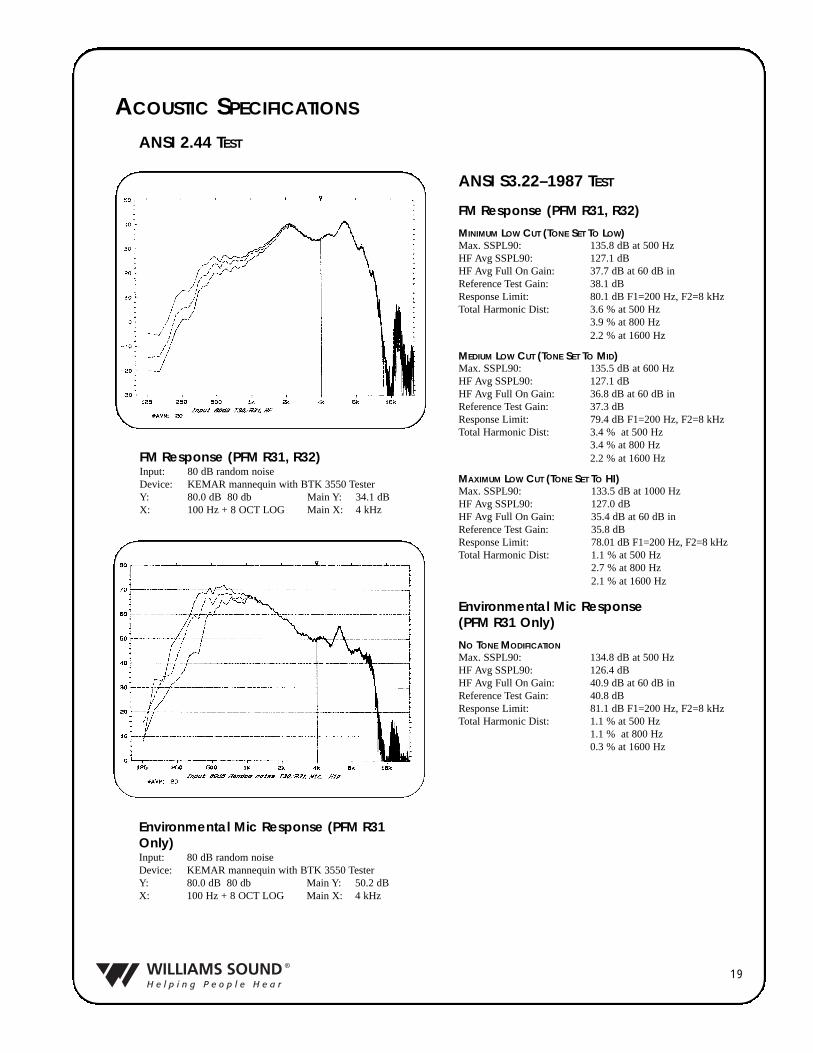
ACOUSTIC SPECIFICATIONS
Environmental Mic Response (PFM R31Only)Input: 80 dB random noiseDevice: KEMAR mannequin with BTK 3550 TesterY: 80.0 dB 80 db Main Y: 50.2 dBX: 100 Hz + 8 OCT LOG Main X: 4 kHz
ANSI S3.22–1987 TEST
FM Response (PFM R31, R32)
MINIMUM LOW CUT (TONE SET TO LOW)Max. SSPL90: 135.8 dB at 500 HzHF Avg SSPL90: 127.1 dBHF Avg Full On Gain: 37.7 dB at 60 dB inReference Test Gain: 38.1 dBResponse Limit: 80.1 dB F1=200 Hz, F2=8 kHzTotal Harmonic Dist: 3.6 % at 500 Hz
3.9 % at 800 Hz2.2 % at 1600 Hz
MEDIUM LOW CUT (TONE SET TO MID)Max. SSPL90: 135.5 dB at 600 HzHF Avg SSPL90: 127.1 dBHF Avg Full On Gain: 36.8 dB at 60 dB inReference Test Gain: 37.3 dBResponse Limit: 79.4 dB F1=200 Hz, F2=8 kHzTotal Harmonic Dist: 3.4 % at 500 Hz
3.4 % at 800 Hz2.2 % at 1600 Hz
MAXIMUM LOW CUT (TONE SET TO HI)Max. SSPL90: 133.5 dB at 1000 HzHF Avg SSPL90: 127.0 dBHF Avg Full On Gain: 35.4 dB at 60 dB inReference Test Gain: 35.8 dBResponse Limit: 78.01 dB F1=200 Hz, F2=8 kHzTotal Harmonic Dist: 1.1 % at 500 Hz
2.7 % at 800 Hz 2.1 % at 1600 Hz
Environmental Mic Response (PFM R31 Only)
NO TONE MODIFICATIONMax. SSPL90: 134.8 dB at 500 HzHF Avg SSPL90: 126.4 dBHF Avg Full On Gain: 40.9 dB at 60 dB inReference Test Gain: 40.8 dBResponse Limit: 81.1 dB F1=200 Hz, F2=8 kHzTotal Harmonic Dist: 1.1 % at 500 Hz
1.1 % at 800 Hz0.3 % at 1600 Hz
FM Response (PFM R31, R32)Input: 80 dB random noiseDevice: KEMAR mannequin with BTK 3550 TesterY: 80.0 dB 80 db Main Y: 34.1 dBX: 100 Hz + 8 OCT LOG Main X: 4 kHz
ANSI 2.44 TEST

© 2007, Williams Sound Corp. MAN 072I


![SAP HowTo Guide - Unlocking User SAPStar [User Guide]](https://img.pdfslide.net/doc/110x75/544ac849b1af9f7c4f8b4bd1/sap-howto-guide-unlocking-user-sapstar-user-guide.jpg)