Embed Size (px)
Citation preview
AXA Power ApS ● Smedebakken 31 – 33 ● DK-5270 Odense N ● Denmark Telefon: + 45 63 18 60 00 ● Fax: + 45 66 18 70 92 ● E-mail: [email protected]
Manual
AXA 2300 Compact 400 Hz Ground Power Unit
With 28 VDC outlet (optional)
Serial no. Type 3GV -200/ -
www.axapower.com

Document no. 578.010 rev.: F Page 2 of 43
Diagrams and drawings are subject to change without prior notice. Latest diagram versions can be found at
www.axapower.com Printed: February 2011
Operation Manual - AXA 2300 Compact – 30 - 90 kVA Index
Document no. 578.010 rev.: D Page 3 of 43
INDEX
1.0 Declaration of Conformity .....................................................................................5
2.0 Safety Instructions ..................................................................................................6
3.0 General Description ................................................................................................7
4.0 Transport and Installation ...................................................................................10
4.1 Storage Before Installation............................................................................................ 10
4.2 Operational and Environmental Conditions after Commissioning ............................... 10
4.3 Transport ....................................................................................................................... 10
4.4 Installation and fastening instructions........................................................................... 11
4.5 Cable Inlet ..................................................................................................................... 12
4.6 Connection of Cables .................................................................................................... 13
4.7 Mains Input ................................................................................................................... 14
4.8 400 Hz Output............................................................................................................... 14
4.9 400 Hz Interlock............................................................................................................ 14
4.10 Control Interface (Remote I/O Terminals).................................................................... 15
4.11 Interface via RS485 or TCP/IP ..................................................................................... 15
5.0 Technical Specifications .......................................................................................16
6.0 Operator’s Instructions ........................................................................................20
6.1 Using the display: ......................................................................................................... 21
7.0 Set-up of Parameters ............................................................................................22
7.1 Adjustable parameters in Set-up Mode:........................................................................ 22
7.2 Lock of set-up parameters............................................................................................. 23
7.3 Cable compensation set-up: .......................................................................................... 23
7.4 Manual Compensation: ................................................................................................. 24
8.0 Service, Maintenance, Overhaul..........................................................................25
8.1 Recommended Maintenance Schedule ......................................................................... 25
8.2 Battery back-up ............................................................................................................. 25
9.0 Trouble Shooting & Repair..................................................................................26
9.1 Fault Guidance .............................................................................................................. 26
10.0 Illustrated Parts List .............................................................................................30

Operation Manual - AXA 2300 Compact – 30 - 90 kVA Index
Document no. 578.010 rev.: F Page 4 of 43
11.0 Options ...................................................................................................................33
578902 Input Autotransformer (diagram 478901)..................................................................... 33
578903 Base module.................................................................................................................. 33
578904 Lockable Door............................................................................................................... 33
578905 Cover for instrumentation ............................................................................................. 33
578906 Remote Control Box ..................................................................................................... 34
578907 Additional Output Contactor (diagram 478901)........................................................... 34
578909 Door Interlock (diagram 478901) ................................................................................. 34
578910 Neutral Conductor Rupture Supervision....................................................................... 35
578911 90% Switch Interlock.................................................................................................... 36
578912 GPU Enable (key reader, bridge, cable drum etc.) ....................................................... 36
578915 RS485 Interface............................................................................................................. 37
578916 TCP/IP Interface ........................................................................................................... 37
578917 Military Interlock .......................................................................................................... 37
578923 Display Heater............................................................................................................... 37
578924 Control Box Heater ....................................................................................................... 37
573956 Service Tool .................................................................................................................. 38
591100 Auto Calibration Plug ................................................................................................... 38
12.0 For units equipped with 28 VDC outlet ..............................................................39
12.1 General Description ...................................................................................................... 39
12.2 Connection of Cables .................................................................................................... 39
12.3 Operator’s Instruction ................................................................................................... 41
12.4 Setup of Parameters ...................................................................................................... 41
12.5 Specifications ................................................................................................................ 42
12.6 Trouble Shooting & Repair.......................................................................................... 43
Operation Manual - AXA 2300 Compact – 30 - 90 kVA Declaration of Conformity
Document no. 578.010 rev.: F Page 5 of 43
1.0 Declaration of Conformity
Operation Manual - AXA 2300 Compact Power– 30 - 90 kVA Safety Instructions
Document no. 578.010 rev.: F Page 6 of 43
2.0 Safety Instructions
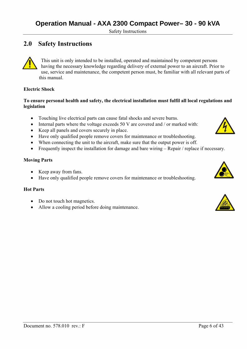
This unit is only intended to be installed, operated and maintained by competent persons having the necessary knowledge regarding delivery of external power to an aircraft. Prior to use, service and maintenance, the competent person must, be familiar with all relevant parts of
this manual. Electric Shock To ensure personal health and safety, the electrical installation must fulfil all local regulations and legislation
Touching live electrical parts can cause fatal shocks and severe burns. Internal parts where the voltage exceeds 50 V are covered and / or marked with: Keep all panels and covers securely in place. Have only qualified people remove covers for maintenance or troubleshooting. When connecting the unit to the aircraft, make sure that the output power is off. Frequently inspect the installation for damage and bare wiring – Repair / replace if necessary.
Moving Parts
Keep away from fans. Have only qualified people remove covers for maintenance or troubleshooting.
Hot Parts
Do not touch hot magnetics. Allow a cooling period before doing maintenance.
Operation Manual - AXA 2300 Compact Power– 30 - 90 kVA General Description
Document no. 578.010 rev.: F Page 7 of 43
3.0 General Description
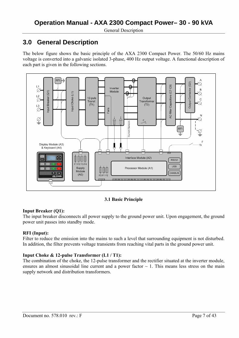
The below figure shows the basic principle of the AXA 2300 Compact Power. The 50/60 Hz mains voltage is converted into a galvanic isolated 3-phase, 400 Hz output voltage. A functional description of each part is given in the following sections.
3.1 Basic Principle Input Breaker (Q1): The input breaker disconnects all power supply to the ground power unit. Upon engagement, the ground power unit passes into standby mode. RFI (Input): Filter to reduce the emission into the mains to such a level that surrounding equipment is not disturbed. In addition, the filter prevents voltage transients from reaching vital parts in the ground power unit. Input Choke & 12-pulse Transformer (L1 / T1): The combination of the choke, the 12-pulse transformer and the rectifier situated at the inverter module, ensures an almost sinusoidal line current and a power factor ~ 1. This means less stress on the main supply network and distribution transformers.
Operation Manual - AXA 2300 Compact Power– 30 - 90 kVA General Description
Document no. 578.010 rev.: F Page 8 of 43
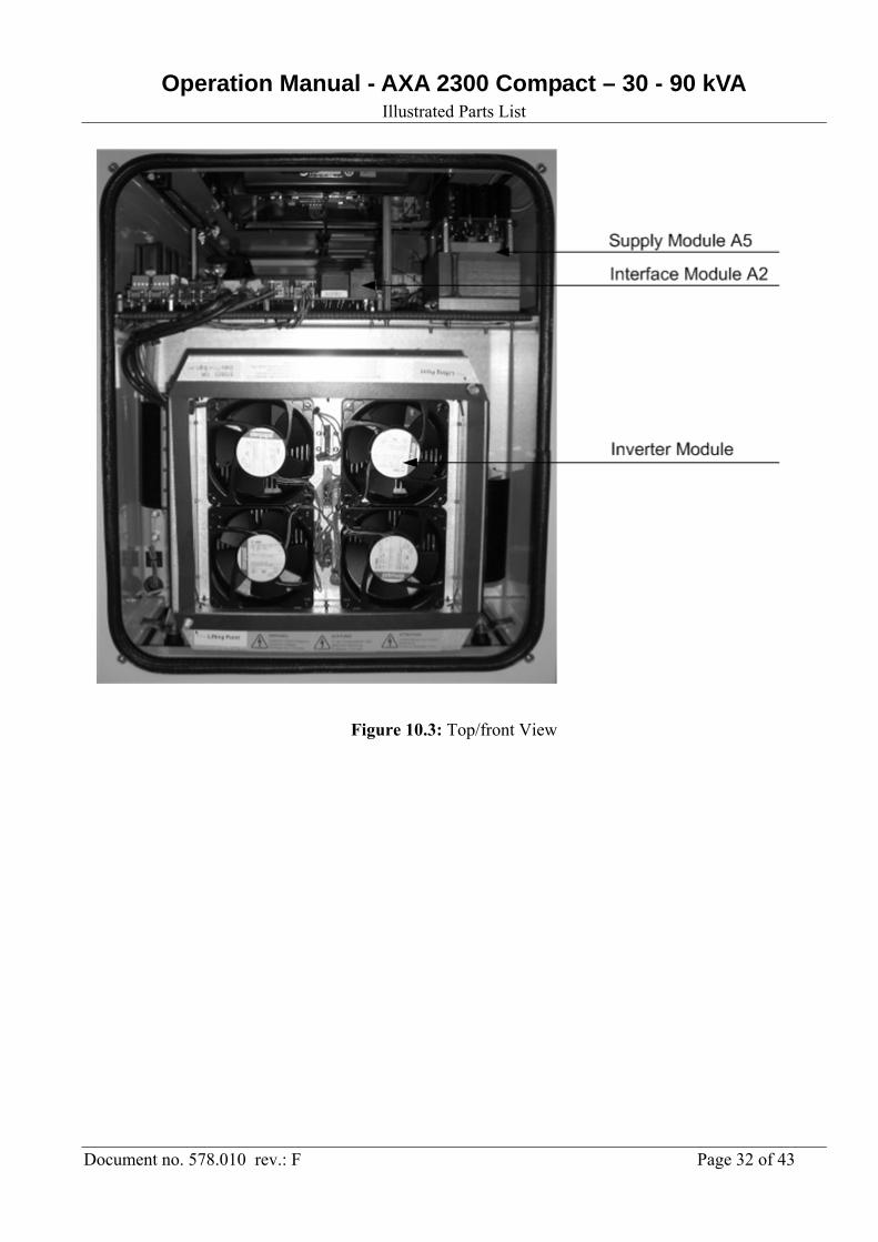
Inverter Module: Beside the rectifier and the DC-filtering capacitors, the module consists of a 3-phase inverter, which generates a 400 Hz voltage system with a very low harmonic content and individual phase control. Two PCBs (gate drives) are used to interface between the control unit and the thyristors / IGBTs. Voltage supervision of the DC-filtering capacitors is likewise performed at the gate drives. Output Transformer (T2): The output transformer secures galvanic separation between in- and output. It also transforms the voltages from the inverter module into the required aircraft voltage (3 x 200/115 V). The filter choke for the output AC-filter is an integrated part of the transformer. AC Filter Capacitors (C7-C9): The harmonic content of the inverter voltage is further reduced by means of the AC Filter, resulting in a total voltage distortion of less than 2%. Complementing the filter choke (integrated in the transformer) and the AC capacitors, the ground power unit is equipped with a RFI-filter that reduces the high frequency emission from the ground power unit. Output Contactor(s): The ground power unit is equipped with one output contactor per outlet. The contactor is engaged at start-up of the corresponding output, and it is disengaged, when the stop button is applied. If the interlock voltage, provided by the aircraft, is not returned to the ground power unit within 1 second, the contactor disengages. Interface Module (A2): The purpose of this module is to interface between the processor module and the rest of the ground power unit. The interface module includes the following functions:
Interface to the display module (e.g. RS485, 24 VDC and EPO link). Pre-fuse for display module (F3) Measuring transformers for supervision of the mains voltage. Measuring transformers for supervision of the 400 Hz output voltage. Interface for gate drives situated at the inverter module. Interface for current sensors situated at the inverter module. Relay control of fans situated at the inverter module. Relay control of output contactor(s). Input for temperature sensors. Pre-fuse of the 24 VDC for control purposes (F1-F2). I/O ports for remote control (Start, Stop etc.). Protected interface for interlock signals. Interface for individual overload protection. Neutral voltage supervision. Neutral conductor rupture supervision. Interface for RS232
Operation Manual - AXA 2300 Compact Power– 30 - 90 kVA General Description
Document no. 578.010 rev.: F Page 9 of 43
Supply Module (A5):
Beside the generation of a 24 VDC control voltage, the module includes fuses for AC-short circuit
protection (F1-F3), MOV’s (varistors) for mains transient protection and a 10 A fuse (F4) for DC
overload protection.
Processor Module (A1):
The processor module is based on a micro-controller and a digital signal processor (DSP). Together
they regulate, supervise and diagnose eventual external and internal faults. As soon as the ground
power unit is connected to the mains, and constantly during normal operation, the processor module
runs through a self-check programme which checks all internal functions of the ground power unit. If an
internal or external error is detected, the display shows the nature of the error. All immediate parameters
related to a shut-down are stored in the ground power unit’s memory.
Display Module & Keyboard (A3 / A4):
The display module serves as the interface for daily operation. Thanks to the RS485 communication, it
is possible to situate the display module up to 1 kilometre away from the ground power unit. Further
information in chapter 6.
Operation Manual - AXA 2300 Compact Power– 30 - 90 kVA Transport and Installation
Document no. 578.010 rev.: F Page 10 of 43
4.0 Transport and Installation
4.1 Storage Before Installation To secure optimal storage conditions prior to installation, it is recommended that the converter is stored inside to protect it from rain and excessive humidity while it is left without power on. Only equipment in seaworthy packing can be stored outside.
4.2 Operational and Environmental Conditions after Commissioning When the converter has been installed and commissioned, we advice that the input is always kept with input power on to provide optimal conditions for the electronic components and to avoid humidity in form of condensed water from reaching vital parts. If for some reason the converter has been without input voltage for a period, a visual inspection should be carried out. In case that humidity is discovered on any internal parts, the parts have to dry out before input voltage is again applied.
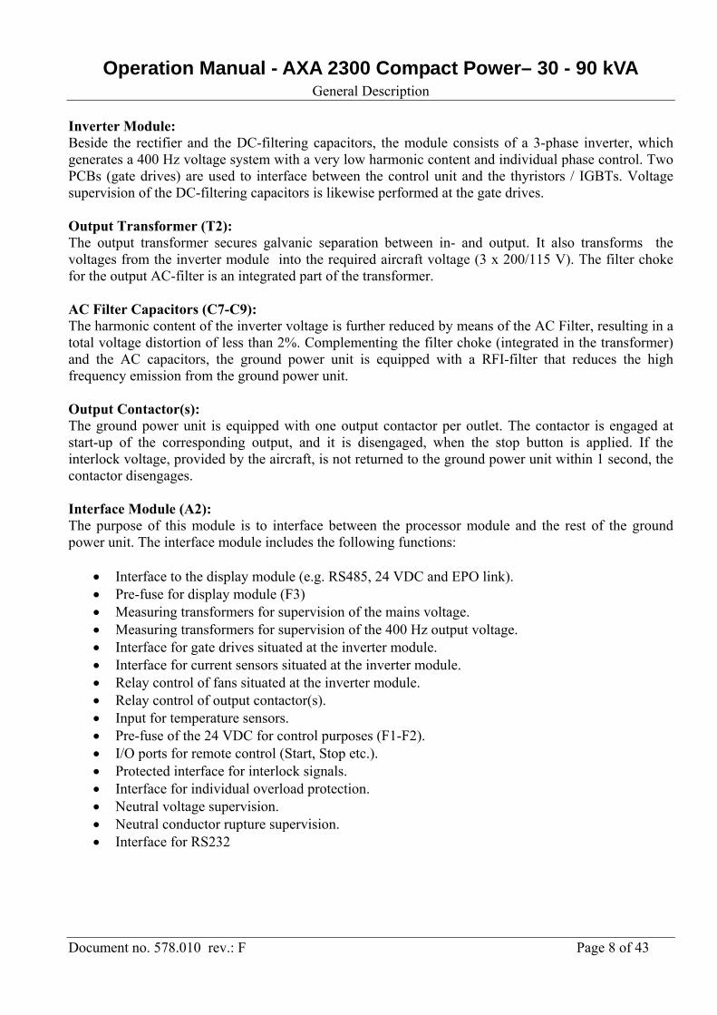
4.3 Transport
Fig. 4.3.1 Access for fork-lift, truck or similar The access requires removal of 8 screws.

Operation Manual - AXA 2300 Compact Power– 30 - 90 kVA Transport and Installation
Document no. 578.010 rev.: F Page 11 of 43
Fig. 4.3.2 Transport by fork-lift truck
4.4 Installation and fastening instructions
Fig. 4.4.1 Foot Print, Fixed Unit
Operation Manual - AXA 2300 Compact Power– 30 - 90 kVA Transport and Installation
Document no. 578.010 rev.: F Page 12 of 43
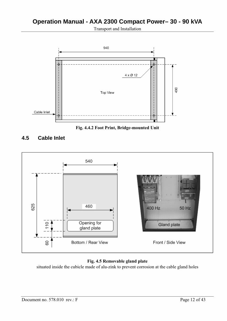
Fig. 4.4.2 Foot Print, Bridge-mounted Unit
4.5 Cable Inlet
Fig. 4.5 Removable gland plate situated inside the cubicle made of alu-zink to prevent corrosion at the cable gland holes
Operation Manual - AXA 2300 Compact Power– 30 - 90 kVA Transport and Installation
Document no. 578.010 rev.: F Page 13 of 43
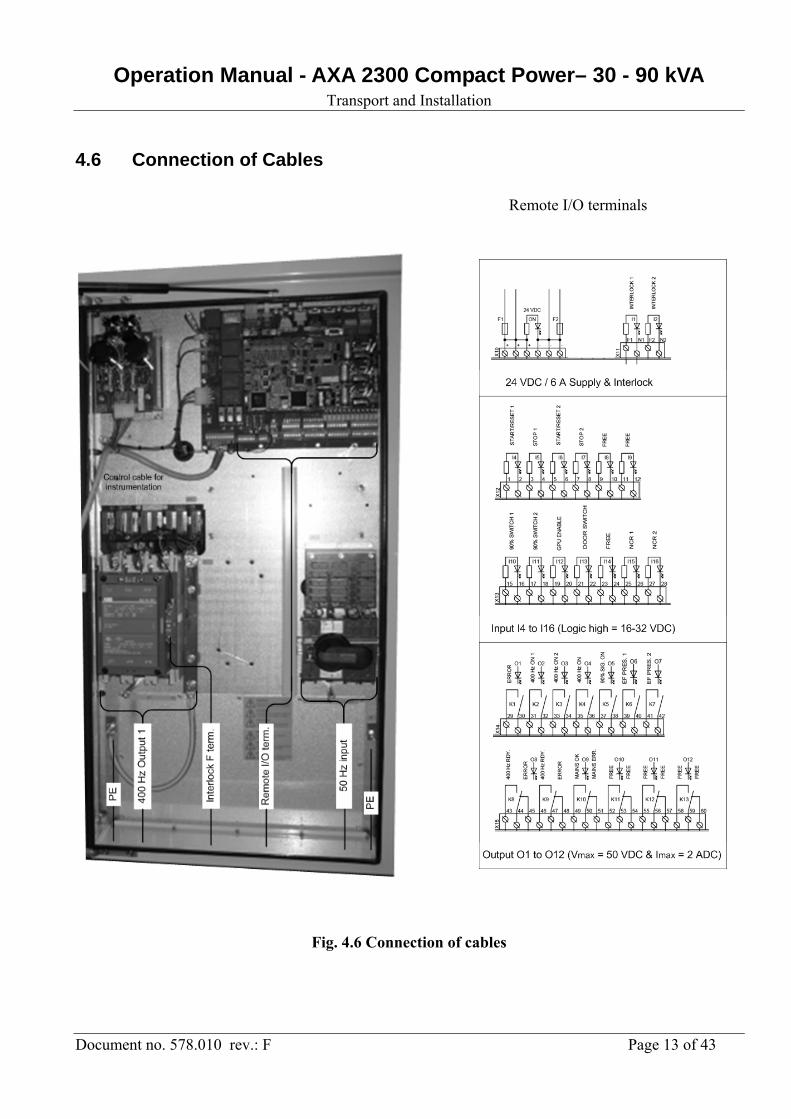
4.6 Connection of Cables
Remote I/O terminals
Fig. 4.6 Connection of cables
Operation Manual - AXA 2300 Compact Power– 30 - 90 kVA Transport and Installation
Document no. 578.010 rev.: F Page 14 of 43
4.7 Mains Input
Due to personal health and safety, the AXA2300 unit must always be protected by grounding the PE terminal ( ).
The mains input connection to the unit should be pre-fused according to section 5.0. As a correct phase sequence is of importance for the function of the AXA2300, the ground power unit is equipped with an automatic phase sequence detection. The detection is automatically carried out when the mains is turned on. If the phase sequence is wrong, this is shown in the display, and correction is made by inversing two phases.
4.8 400 Hz Output At delivery, the 400 Hz neutral is connected to the protective earthing terminal (PE). If a floating output is required, the yellow/green connection wire must be removed.
Independently of installation method, it is mandatory that local regulations and legislation are fulfilled in order to ensure personal health and safety.
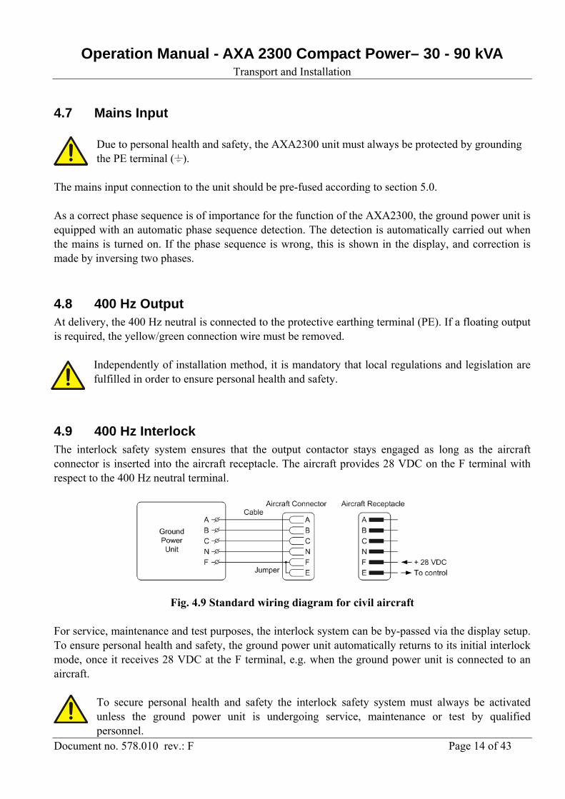
4.9 400 Hz Interlock The interlock safety system ensures that the output contactor stays engaged as long as the aircraft connector is inserted into the aircraft receptacle. The aircraft provides 28 VDC on the F terminal with respect to the 400 Hz neutral terminal.
Fig. 4.9 Standard wiring diagram for civil aircraft For service, maintenance and test purposes, the interlock system can be by-passed via the display setup. To ensure personal health and safety, the ground power unit automatically returns to its initial interlock mode, once it receives 28 VDC at the F terminal, e.g. when the ground power unit is connected to an aircraft.
To secure personal health and safety the interlock safety system must always be activated unless the ground power unit is undergoing service, maintenance or test by qualified personnel.
Operation Manual - AXA 2300 Compact Power– 30 - 90 kVA Transport and Installation
Document no. 578.010 rev.: F Page 15 of 43
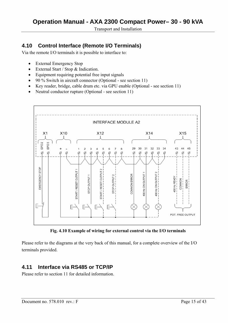
4.10 Control Interface (Remote I/O Terminals) Via the remote I/O terminals it is possible to interface to:
External Emergency Stop External Start / Stop & Indication. Equipment requiring potential free input signals 90 % Switch in aircraft connector (Optional - see section 11) Key reader, bridge, cable drum etc. via GPU enable (Optional - see section 11) Neutral conductor rupture (Optional - see section 11)
Fig. 4.10 Example of wiring for external control via the I/O terminals
Please refer to the diagrams at the very back of this manual, for a complete overview of the I/O
terminals provided.
4.11 Interface via RS485 or TCP/IP Please refer to section 11 for detailed information.
Operation Manual - AXA 2300 Compact – 30 - 90 kVA Technical Specifications
Document no. 578.010 rev.: F Page 16 of 43
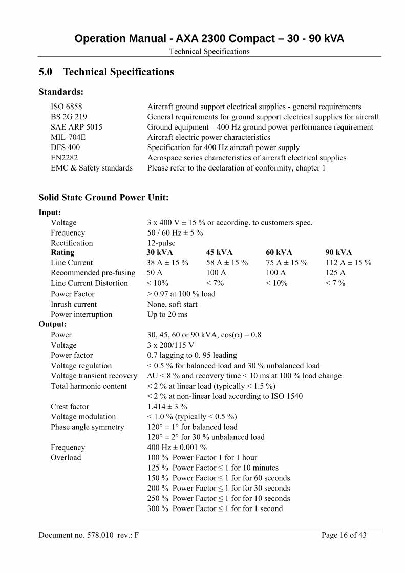
5.0 Technical Specifications
Standards:
ISO 6858 Aircraft ground support electrical supplies - general requirements BS 2G 219 General requirements for ground support electrical supplies for aircraft SAE ARP 5015 Ground equipment – 400 Hz ground power performance requirement MIL-704E Aircraft electric power characteristics DFS 400 Specification for 400 Hz aircraft power supply EN2282 Aerospace series characteristics of aircraft electrical supplies EMC & Safety standards Please refer to the declaration of conformity, chapter 1
Solid State Ground Power Unit:
Input: Voltage 3 x 400 V ± 15 % or according. to customers spec. Frequency 50 / 60 Hz ± 5 % Rectification 12-pulse Rating 30 kVA 45 kVA 60 kVA 90 kVA Line Current 38 A ± 15 % 58 A ± 15 % 75 A ± 15 % 112 A ± 15 % Recommended pre-fusing 50 A 100 A 100 A 125 A Line Current Distortion < 10% < 7% < 10% < 7 % Power Factor > 0.97 at 100 % load Inrush current None, soft start Power interruption Up to 20 ms Output: Power 30, 45, 60 or 90 kVA, cos() = 0.8 Voltage 3 x 200/115 V Power factor 0.7 lagging to 0. 95 leading Voltage regulation < 0.5 % for balanced load and 30 % unbalanced load Voltage transient recovery U < 8 % and recovery time < 10 ms at 100 % load change Total harmonic content
< 2 % at linear load (typically < 1.5 %) < 2 % at non-linear load according to ISO 1540
Crest factor 1.414 ± 3 % Voltage modulation < 1.0 % (typically < 0.5 %) Phase angle symmetry 120° ± 1° for balanced load
120° ± 2° for 30 % unbalanced load Frequency 400 Hz ± 0.001 % Overload 100 % Power Factor 1 for 1 hour
125 % Power Factor ≤ 1 for 10 minutes 150 % Power Factor ≤ 1 for for 60 seconds 200 % Power Factor ≤ 1 for for 30 seconds 250 % Power Factor ≤ 1 for for 10 seconds 300 % Power Factor ≤ 1 for for 1 second
Operation Manual - AXA 2300 Compact – 30 - 90 kVA Technical Specifications
Document no. 578.010 rev.: F Page 17 of 43
Efficiency:
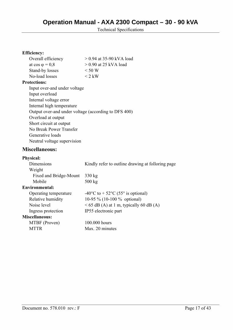
Overall efficiency > 0.94 at 35-90 kVA load at cos = 0,8 > 0.90 at 25 kVA load Stand-by losses < 50 W No-load losses < 2 kW Protections: Input over-and under voltage Input overload Internal voltage error Internal high temperature Output over-and under voltage (according to DFS 400) Overload at output Short circuit at output No Break Power Transfer Generative loads Neutral voltage supervision
Miscellaneous:
Physical: Dimensions Kindly refer to outline drawing at folloring page Weight Fixed and Bridge-Mount 330 kg Mobile 500 kg Environmental: Operating temperature -40°C to + 52°C (55° is optional) Relative humidity 10-95 % (10-100 % optional) Noise level < 65 dB (A) at 1 m, typically 60 dB (A) Ingress protection IP55 electronic part Miscellaneous: MTBF (Proven) 100.000 hours MTTR Max. 20 minutes
Operation Manual - AXA 2300 Compact – 30 - 90 kVA Technical Specifications
Document no. 578.010 rev.: F Page 18 of 43
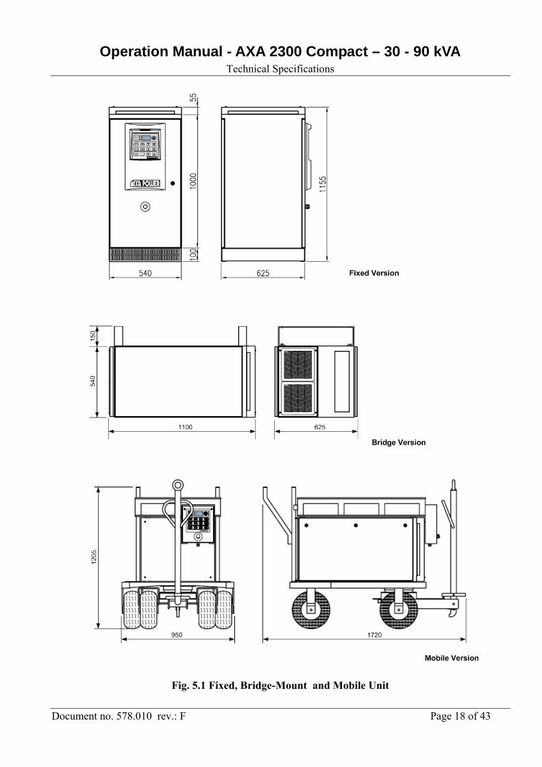
Fig. 5.1 Fixed, Bridge-Mount and Mobile Unit

Operation Manual - AXA 2300 Compact – 30 - 90 kVA Technical Specifications
Document no. 578.010 rev.: F Page 19 of 43
Fig. 5.2 Fixed and Mobile Unit with base Module
Operation Manual - AXA 2300 Compact – 30 - 90 kVA Operator’s Instructions
Document no. 578.010 rev.: F Page 20 of 43
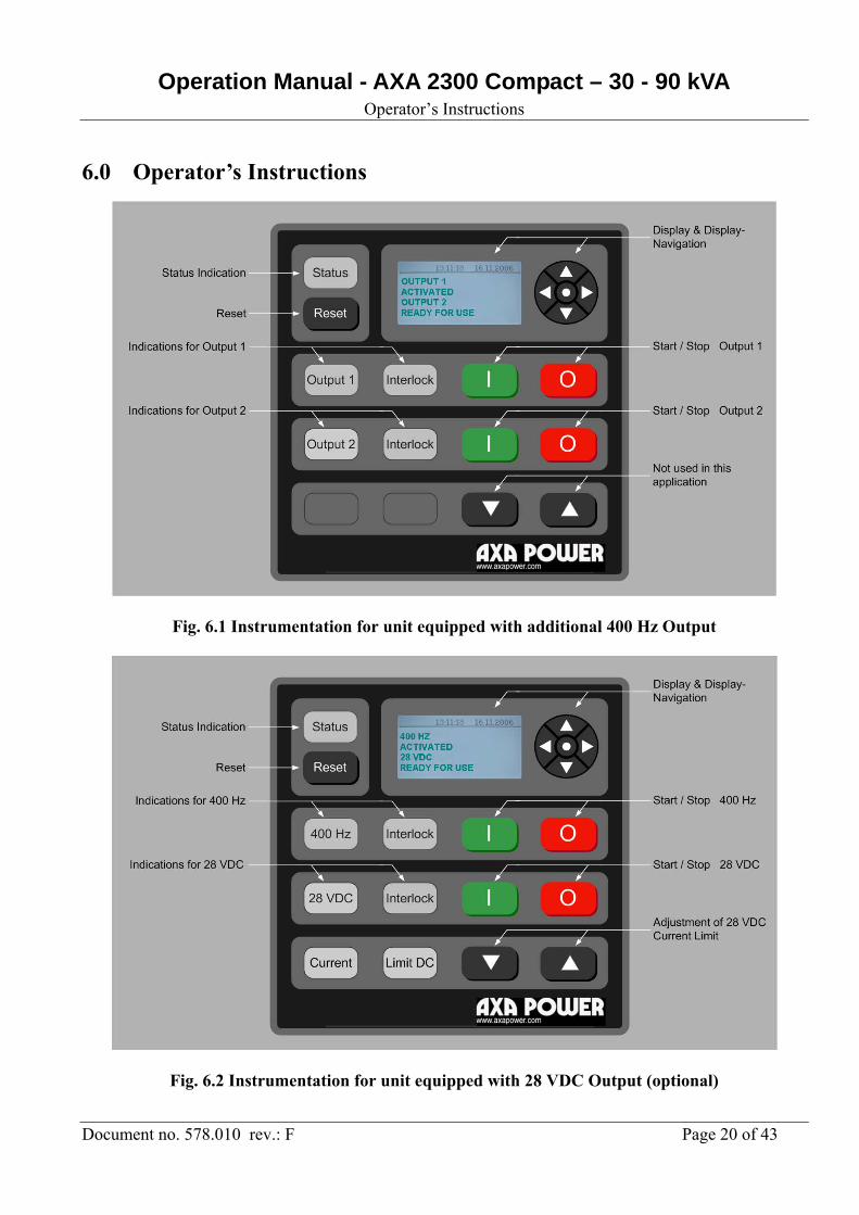
6.0 Operator’s Instructions
Fig. 6.1 Instrumentation for unit equipped with additional 400 Hz Output
Fig. 6.2 Instrumentation for unit equipped with 28 VDC Output (optional)
Operation Manual - AXA 2300 Compact – 30 - 90 kVA Operator’s Instructions
Document no. 578.010 rev.: F Page 21 of 43
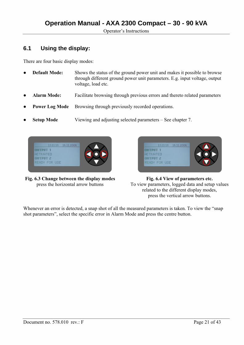
6.1 Using the display: There are four basic display modes: ● Default Mode: Shows the status of the ground power unit and makes it possible to browse
through different ground power unit parameters. E.g. input voltage, output voltage, load etc.
● Alarm Mode: Facilitate browsing through previous errors and thereto related parameters ● Power Log Mode Browsing through previously recorded operations.
● Setup Mode Viewing and adjusting selected parameters – See chapter 7.
Whenever an error is detected, a snap shot of all the measured parameters is taken. To view the “snap shot parameters”, select the specific error in Alarm Mode and press the centre button.
Fig. 6.3 Change between the display modes press the horizontal arrow buttons
Fig. 6.4 View of parameters etc. To view parameters, logged data and setup values
related to the different display modes, press the vertical arrow buttons.
Operation Manual - AXA 2300 Compact – 30 - 90 kVA Set-up of Parameters
Document no. 578.010 rev.: F Page 22 of 43
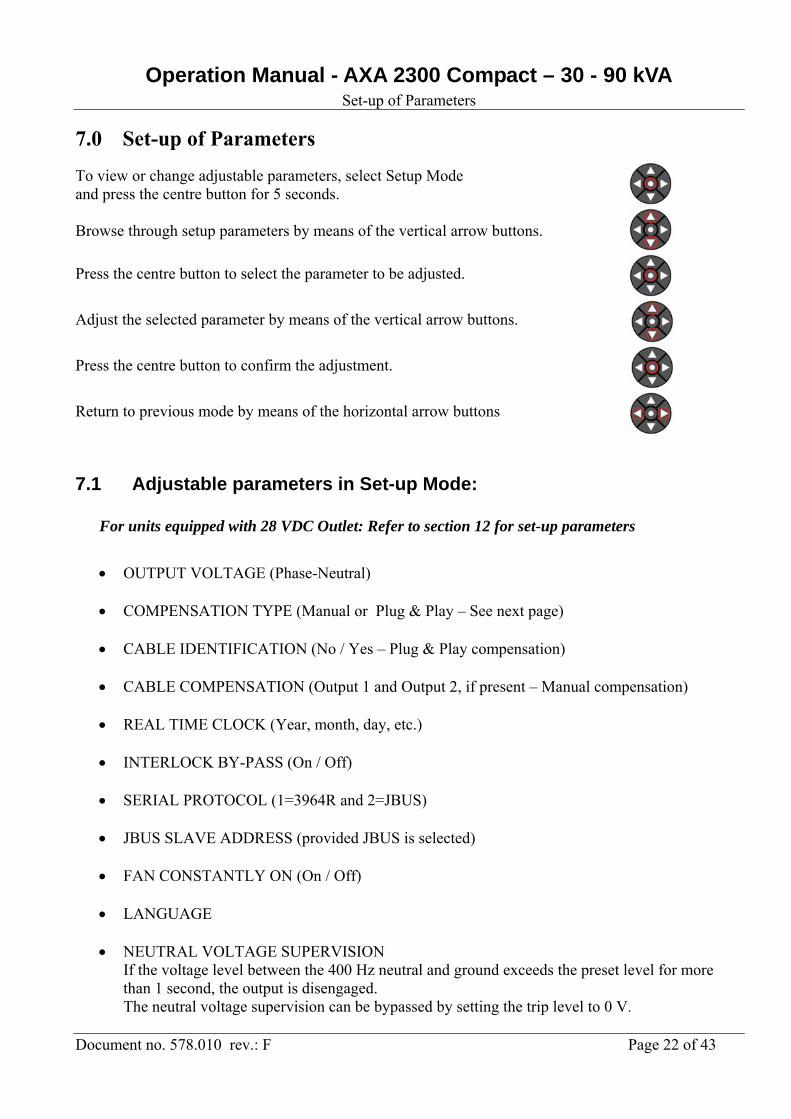
7.0 Set-up of Parameters
To view or change adjustable parameters, select Setup Mode and press the centre button for 5 seconds. Browse through setup parameters by means of the vertical arrow buttons.
Press the centre button to select the parameter to be adjusted.
Adjust the selected parameter by means of the vertical arrow buttons.
Press the centre button to confirm the adjustment.
Return to previous mode by means of the horizontal arrow buttons
7.1 Adjustable parameters in Set-up Mode:
For units equipped with 28 VDC Outlet: Refer to section 12 for set-up parameters
OUTPUT VOLTAGE (Phase-Neutral)
COMPENSATION TYPE (Manual or Plug & Play – See next page)
CABLE IDENTIFICATION (No / Yes – Plug & Play compensation)
CABLE COMPENSATION (Output 1 and Output 2, if present – Manual compensation)
REAL TIME CLOCK (Year, month, day, etc.)
INTERLOCK BY-PASS (On / Off)
SERIAL PROTOCOL (1=3964R and 2=JBUS)
JBUS SLAVE ADDRESS (provided JBUS is selected)
FAN CONSTANTLY ON (On / Off)
LANGUAGE
NEUTRAL VOLTAGE SUPERVISION If the voltage level between the 400 Hz neutral and ground exceeds the preset level for more than 1 second, the output is disengaged. The neutral voltage supervision can be bypassed by setting the trip level to 0 V.

Operation Manual - AXA 2300 Compact – 30 - 90 kVA Set-up of Parameters
Document no. 578.010 rev.: F Page 23 of 43
7.2 Lock of set-up parameters
To avoid unintentional modification of the
Set-up parameters, it is possible to block the
access to the Set-up Mode, by means of a DIP
switch situated at the Display Module A3.
Fig. 7.1 Display Module A3
7.3 Cable compensation set-up: Plug & Play: The unique Plug & Play compensation system automatically identifies all relevant cable parameters and keep the voltage at the aircraft connector constant, at all aircraft loads.
1. Short circuit the aircraft connector by means of the Auto Calibration Plug (p/n 591100).
2. Select compensation type to “PLUG & PLAY” via Setup Mode.
3. Change “IDENTIFY CABLE” to “YES”
4. Initiate the cable identification process by pressing the ground power unit’s
START button.
5. Within a few seconds, the cable parameters are identified and the ground power unit returns to Default Mode.
6. Remove the Auto Calibration Plug and the ground power unit is ready for use.
Please be aware that it is not possible to use the Plug & Play voltage compensation if the ground power unit is equipped with two or more outlets !
Operation Manual - AXA 2300 Compact – 30 - 90 kVA Set-up of Parameters
Document no. 578.010 rev.: F Page 24 of 43
7.4 Manual Compensation: This is the traditional (Manual) method of cable compensation, where the output voltage is increased in proportion to the load current (Volt / 100 A). This method it usable where the influence of unsymme-trical cables, unbalanced load and varying power factor can be neglected. Manual compensation is applicable for ground power units equipped with two outlets.
1. Apply nominal load at the aircraft connector.
2. Select compensation type to “MANUAL” via Setup Mode.
3. Select “CABLE COMP. OUTPUT 1”.
4. Adjust the compensation by means of the vertical arrow buttons until the voltage at the aircraft connectors equals the no load value.
If the ground power unit is equipped with a second outlet, the same procedure is applied for “OUTPUT 2”.

Operation Manual - AXA 2300 Compact – 30 - 90 kVA Service, Maintenance and Overhaul
Document no. 578.010 rev.: F Page 25 of 43
8.0 Service, Maintenance, Overhaul To make certain that the unit is always ready for use, it must be maintained on a regular basis.
Only have qualified people remove covers for service, maintenance or overhauls.
8.1 Recommended Maintenance Schedule Check Aircraft connector. Quarterly
Check Output cable for damaged insulation. Quarterly
Verify function of 90 % Switch, if present. Quarterly
Check Air-filters - Wash or change as appropriate. Quarterly
Check that all fans are running properly (constantly on via display). Yearly
Check rubber sealing at front door, rear panel and top cover Yearly
Check internal bolt/screw and wire connections. Yearly
Check vibration dampers (via rear panel). Yearly
Visual inspection of PCB's - control unit / gate drive. Yearly
Control of the output contactors' contact sets and coil Yearly
Control of output voltage at aircraft connector (with and without load) Yearly
Especially for mobile units Check tyres for wear and tear Yearly
Check correct air pressure (4,3 Bar = 62 PSI) Quarterly
8.2 Battery back-up
Situated on the processor board, a lithium battery ensures that set-up data etc. are not lost during mains
drop-outs. The expected life of the battery is approx. 10 years. However, a low battery voltage does not
affect the internal safety system of the GPU that monitors the output voltage, among others. Thus
aircraft connected to the GPU are not exposed to any danger. To avoid loss of data we recommend to
change the battery after 8-9 years of use.
Operation Manual - AXA 2300 Compact – 30 - 90 kVA Trouble Shooting & Repair
Document no. 578.010 rev.: F Page 26 of 43
9.0 Trouble Shooting & Repair
Only have qualified people remove covers for troubleshooting and repair. Please be aware
that the DC Capacitors can remain charged to a dangerous voltage up to 5 minutes after the
mains input has been disconnected.
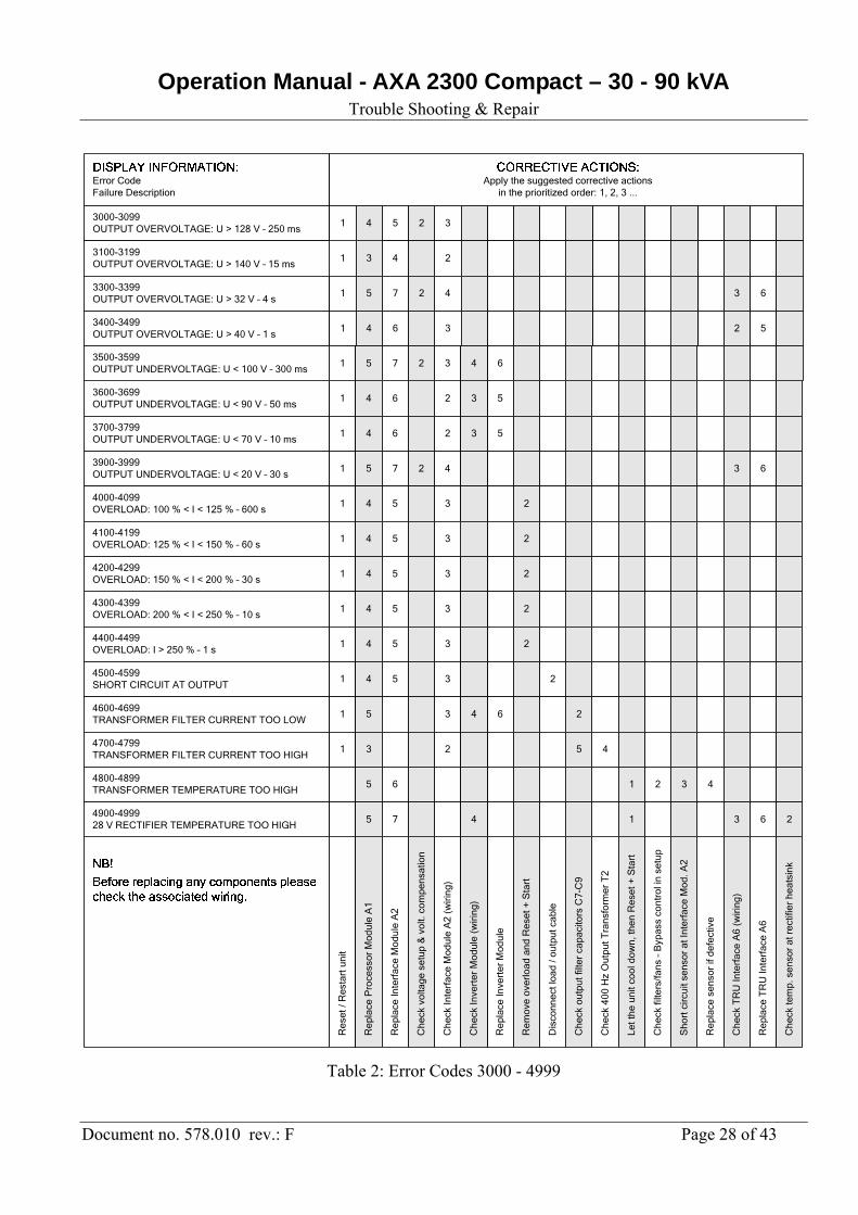
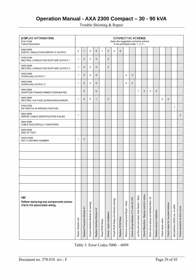
Usually the display text provides sufficient information to get the ground power unit into operation again. In case the display is blank, please check fuse F1, F2 and F4 at the Supply Module A5 and fuse F3 at the Interface Module A2. If the displayed text does not provide sufficient information to solve the problem, Table 1, Table 2 and Table 3 suggests prioritized corrective actions to be carried out for each error code. Additional error-information regarding the input voltage, output voltage, transformer filter current, overload and short circuit can be derived from the error code according to the following directions: Error Code XX01 refers to output phase A (or input phase L1) Error Code XX02 refers to output phase B (or input phase L2) Error Code XX03 refers to output phase A and B (or input phase L1 and L2) Error Code XX04 refers to output phase C (or input phase L3) Error Code XX05 refers to output phase A and C (or input phase L1 and L3) Error Code XX06 refers to output phase B and C (or input phase L2 and L3) Error Code XX07 refers to all output phases (or all input phases) Examples: Error Code 1001 refers to a too high input voltage at phase L1. Error Code 4007 refers to overload at all 3 output phases.
9.1 Fault Guidance In case that you need to contact AXA for further fault guidance, please do not forget to enter the serial number of the GPU (can be found at the rating plate) and the actual error code on the fault finding formula that can downloaded from www.axapower.com (pls. refer to section After Sales Department)

Operation Manual - AXA 2300 Compact – 30 - 90 kVA Trouble Shooting & Repair
Document no. 578.010 rev.: F Page 27 of 43
0000-0099NO ERROR LOGGED YET
10100-0199LOGGING WAS NOT COMPLET. SUCCESFULLY
3
0150WATCHDOG RESET OCCURED
0200-0299INTERNAL DC SUPPLY VOLTAGE ERROR
0400-0499AC SOFTSTART ERROR
0500-0599INVERTER ERROR
1000-1099INPUT VOLTAGE TOO HIGH
1100-1199INPUT VOLTAGE TOO LOW
0600-0699INPUT VOLT. – PHASE SEQUENCY NOT FOUND
0700-0799INPUT VOLTAGE – FREQUENCY TOO HIGH
0900-0999INPUT VOLTAGE – PHASE SEQUENCY WRONG
1500-1599DC VOLTAGE < 350 V
1600-1699DC VOLTAGE > 850 V
1700-1799DC CAPACITOR SHARING ERROR
Res
et /
Res
tart
uni
t
Rep
lace
Pro
cess
or M
odul
e A
1
Rep
lace
Inte
rfac
e M
odul
e A
2
Rep
lace
Pov
er S
uppl
y M
odul
e A
5
Che
ck P
ower
Sup
ply
volta
ge (
> 2
0 V
DC
)
Che
ck In
vert
er M
odul
e (w
iring
/ ga
tedr
ive)
Rep
lace
Inve
rter
Mod
ule
Che
ck fu
se F
1-F
2 at
Inte
rfac
e M
odul
e A
2
Che
ck fu
se F
1-F
3 at
Sup
ply
Mod
ule
A5
Che
ck e
lect
roly
tic c
ap. a
t Inv
erte
r M
odul
e
Che
ck fi
lters
/fans
-by
pass
con
trol
via
set
up
Che
ck R
1 at
Inve
rter
Mod
ule
(2 x
4,7
koh
m)
Che
ck in
put v
olta
ge
Che
ck D
C v
olta
ge v
ia d
ispl
ay A
larm
Mod
e
Che
ck o
utpu
t vol
tage
via
dis
p. A
larm
Mod
e
Che
ck In
terf
ace
Mod
ule
(wiri
ng)
Error CodeFailure Description
Apply the suggested corrective actionsin the prioritized order: 1, 2, 3 ...
42
1 2
1 4 53 2
1 2
1 5 7 3 62 4
1 2
1 4 5 23
23
1 4 5 32
1 4 5 23
1 4 5 23
1 5 3 4 2
1 5 3 4 2
1 7 3 6 542
0800-0899INPUT VOLTAGE – FREQUENCY TOO LOW
1 4 5
Che
ck s
uppl
y vo
ltage
to fa
ns (
24 V
DC
)
Che
ck E
mer
genc
y S
top
2000-2099INVERTER TEMPERATURE TOO HIGH
0300-0399EMERGENCY STOP ACTIVATED OR FUSE BLOWN
1 5 4 6 2
2
3
1
2100-2199GATE VOLTAGE ERROR
1 3 2 4
Table 1: Error Codes 0000 - 2199
Operation Manual - AXA 2300 Compact – 30 - 90 kVA Trouble Shooting & Repair
Document no. 578.010 rev.: F Page 28 of 43
3000-3099OUTPUT OVERVOLTAGE: U > 128 V – 250 ms
13100-3199OUTPUT OVERVOLTAGE: U > 140 V – 15 ms
3
3300-3399OUTPUT OVERVOLTAGE: U > 32 V – 4 s
3400-3499OUTPUT OVERVOLTAGE: U > 40 V – 1 s
3600-3699OUTPUT UNDERVOLTAGE: U < 90 V – 50 ms
3700-3799OUTPUT UNDERVOLTAGE: U < 70 V – 10 ms
4300-4399OVERLOAD: 200 % < I < 250 % – 10 s
4400-4499OVERLOAD: I > 250 % – 1 s
3900-3999OUTPUT UNDERVOLTAGE: U < 20 V – 30 s
4000-4099OVERLOAD: 100 % < I < 125 % – 600 s
4200-4299OVERLOAD: 150 % < I < 200 % – 30 s
4500-4599SHORT CIRCUIT AT OUTPUT
4600-4699TRANSFORMER FILTER CURRENT TOO LOW
4700-4799TRANSFORMER FILTER CURRENT TOO HIGH
Res
et /
Res
tart
uni
t
Rep
lace
Pro
cess
or M
odul
e A
1
Rep
lace
Inte
rfac
e M
odul
e A
2
Che
ck In
terf
ace
Mod
ule
A2
(wiri
ng)
Che
ck v
olta
ge s
etup
& v
olt.
com
pens
atio
n
Rep
lace
Inve
rter
Mod
ule
Rem
ove
over
load
and
Res
et +
Sta
rt
Che
ck 4
00 H
z O
utpu
t Tra
nsfo
rmer
T2
Let t
he u
nit c
ool d
own,
then
Res
et +
Sta
rt
Rep
lace
sen
sor
if de
fect
ive
Che
ck T
RU
Inte
rfac
e A
6 (w
iring
)
Sho
rt c
ircui
t sen
sor
at In
terf
ace
Mod
. A2
Che
ck o
utpu
t filt
er c
apac
itors
C7-
C9
Che
ck fi
lters
/fans
– B
ypas
s co
ntro
l in
setu
p
Che
ck In
vert
er M
odul
e (w
iring
)
Dis
conn
ect l
oad
/ out
put c
able
Error CodeFailure Description
Apply the suggested corrective actionsin the prioritized order: 1, 2, 3 ...
1 4 5 32
4 2
1 5 7 42 3
1 4 6 3 2
1 4 6 2 53
1 4 6 2 53
1 5 7 42 3
1 4 5 3 2
2
1 4 5 3 2
1 4 5 3 2
1 4 5 3 2
1 4 5 3 2
1 5 3 6 24
1 3 2 45
4100-4199OVERLOAD: 125 % < I < 150 % – 60 s
1 4 5 3
Rep
lace
TR
U In
terf
ace
A6
Che
ck te
mp.
sen
sor
at r
ectif
ier
heat
sink
6
5
6
4800-4899TRANSFORMER TEMPERATURE TOO HIGH
13500-3599OUTPUT UNDERVOLTAGE: U < 100 V – 300 ms
5
5 6 1 432
7 32 64
4900-499928 V RECTIFIER TEMPERATURE TOO HIGH
5 7 1 34 6 2
Table 2: Error Codes 3000 - 4999
Operation Manual - AXA 2300 Compact – 30 - 90 kVA Trouble Shooting & Repair
Document no. 578.010 rev.: F Page 29 of 43
5000-5099EARTH / INSULATION ERROR AT OUTPUT
15100-5199NEUTRAL CONDUCTOR RUPTURE OUTPUT 1
4
5200-5299NEUTRAL CONDUCTOR RUPTURE OUTPUT 2
5300-5399OVERLOAD OUTPUT 1
5500-5599ADAPTION TRANSFORMER OVERHEATED
5600-5699NEUTRAL VOLTAGE SUPERVISION ERROR
XX00-XX99NOT A DEFINED NUMBER
5700-5799DIP SWITCH IN WRONG POSITION
5800-5899ERROR: CABLE IDENTIFICATION FAILED
6000-6099END OF TEST
Res
et /
Res
tart
uni
t
Rep
lace
Pro
cess
or M
odul
e A
1
Che
ck In
terf
ace
Mod
ule
A2
(wiri
ng)
Res
et R
CM
Rel
ay
Rep
lace
Inte
rfac
e M
odul
e A
2
Che
ck R
CM
Rel
ay a
nd S
enso
r (w
irin
g)
Rep
lace
RC
M R
elay
Let t
he u
nit c
ool d
own,
then
Res
et +
Sta
rt
Che
ck fi
lters
/fans
– B
ypas
s co
ntro
l in
setu
p
Che
ck s
etup
val
ue
Che
ck o
utpu
t for
insu
latio
n fa
ilure
s
Rep
lace
sen
sor
if de
fect
ive
Che
ck w
irin
g be
twee
n C
T’s
and
A2
(X5)
Sho
rt c
ircui
t sen
sor
at In
terf
ace
Mod
. A2
Che
ck /
repa
ir in
stal
latio
n
Rem
ove
over
load
and
Res
et +
Sta
rt
Error CodeFailure Description
Apply the suggested corrective actionsin the prioritized order: 1, 2, 3 ...
2 7 5 18 4 63
3 5 2
1 4 3 5 2
1 5 4 6 32
5 6 1 2 43
1 6 5 7 2 43
1
1 2
5900-5999CABLE SUCCESFULLY IDENTIFIED
Set
sw
itche
s (S
W2)
acc
. to
labe
l
Che
ck p
rese
nce
of s
hort
circ
uit.
1
2
15400-5499OVERLOAD OUTPUT 2
5 4 6 32
Table 3: Error Codes 5000 – 6099
Operation Manual - AXA 2300 Compact – 30 - 90 kVA Illustrated Parts List
Document no. 578.010 rev.: F Page 30 of 43
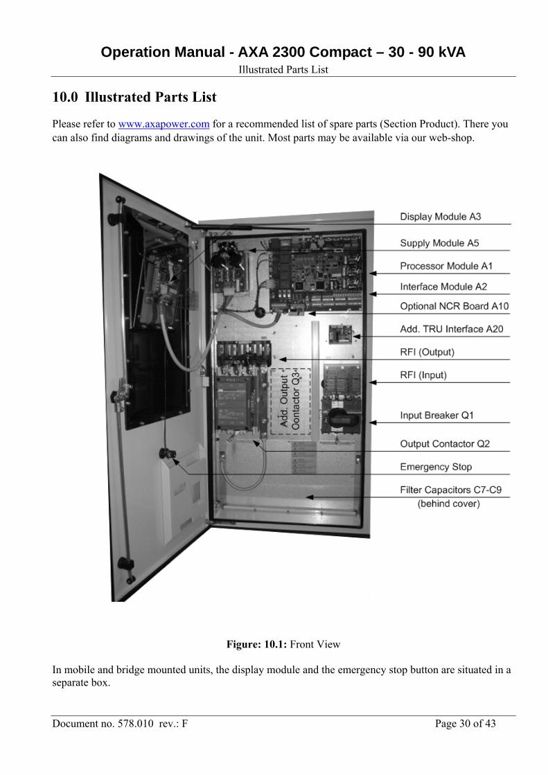
10.0 Illustrated Parts List
Please refer to www.axapower.com for a recommended list of spare parts (Section Product). There you can also find diagrams and drawings of the unit. Most parts may be available via our web-shop.
Figure: 10.1: Front View
In mobile and bridge mounted units, the display module and the emergency stop button are situated in a separate box.
Operation Manual - AXA 2300 Compact – 30 - 90 kVA Illustrated Parts List
Document no. 578.010 rev.: F Page 31 of 43
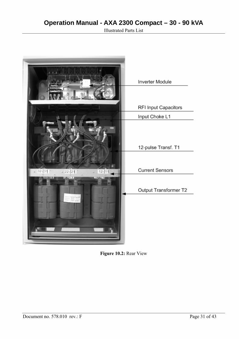
Figure 10.2: Rear View
Operation Manual - AXA 2300 Compact – 30 - 90 kVA Illustrated Parts List
Document no. 578.010 rev.: F Page 32 of 43
Figure 10.3: Top/front View

Operation Manual - AXA 2300 Compact – 30 - 90 kVA Options and Diagrams
Document no. 578.010 rev.: F Page 33 of 43
11.0 Options
This ground power unit might be equipped with one ore more of the following options:
578902 Input Autotransformer (diagram 478901)
(Only valid for units with ratings of 60 kVA max.) Transformer, which enables connection of the ground power unit to the following mains voltages:
3 x 200 VAC (recommended pre-fuse: 315 A)
3 x 230 VAC (recommended pre-fuse: 315 A) The transformer is placed in a base module (kindly refer to section 5)
578903 Base module
Additional base module, which extends the height /length of the ground power unit by 345 mm and the
weight by 20 kg. (kindly refer to section 5)
578904 Lockable Door
As a standard, the GPU is supplied with a quarter-turn lock intended for a
double bit 5 mm pin key. One key is supplied per ground power unit.
On an optional basis, the ground power unit can be supplied with a lockable
swing handle at the front door. The handle is locked by a profile cylinder
according to DIN 18252 (depth = 40 mm). Each ground power unit is supplied
with 2 identical keys.
578905 Cover for instrumentation
A protective cover in front of the operator’s panel.

Operation Manual - AXA 2300 Compact – 30 - 90 kVA Options and Diagrams
Document no. 578.010 rev.: F Page 34 of 43
578906 Remote Control Box
The control box is used for operation of the ground power unit, if placed away from the aircraft
parking position or placed under a passenger boarding bridge.
578907 Additional Output Contactor (diagram 478901) AXA 2300 compact ground power units are as a standard equipped with one output contactor. All models are, however, prepared for an additional output contactor.
578909 Door Interlock (diagram 478901) Interlock, which ensures that the ground power unit passes into stand-by mode if the door is opened.
Operation Manual - AXA 2300 Compact – 30 - 90 kVA Options and Diagrams
Document no. 578.010 rev.: F Page 35 of 43
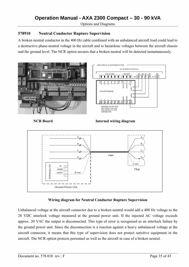
578910 Neutral Conductor Rupture Supervision
A broken neutral conductor in the 400 Hz cable combined with an unbalanced aircraft load could lead to
a destructive phase-neutral voltage in the aircraft and to hazardous voltages between the aircraft chassis
and the ground level. The NCR option secures that a broken neutral will be detected instantaneously.
NCR Board Internal wiring diagram
Wiring diagram for Neutral Conductor Rupture Supervision
Unbalanced voltage at the aircraft connector due to a broken neutral would add a 400 Hz voltage to the
28 VDC interlock voltage measured at the ground power unit. If the injected AC voltage exceeds
approx. 20 VAC the output is disconnected. This type of error is recognised as an interlock failure by
the ground power unit. Since the disconnection is a reaction against a heavy unbalanced voltage at the
aircraft connector, it means that this type of supervision does not protect sensitive equipment in the
aircraft. The NCR option protects personnel as well as the aircraft in case of a broken neutral.
Operation Manual - AXA 2300 Compact – 30 - 90 kVA Options and Diagrams
Document no. 578.010 rev.: F Page 36 of 43
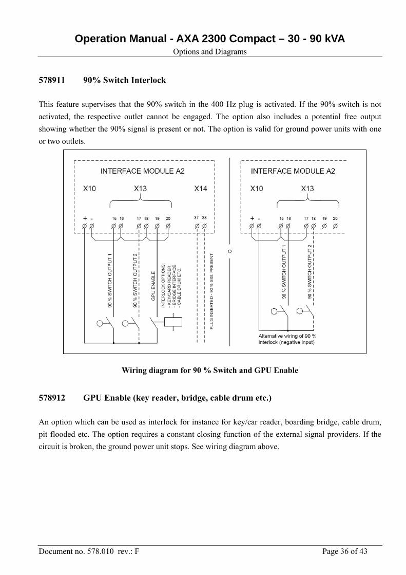
578911 90% Switch Interlock
This feature supervises that the 90% switch in the 400 Hz plug is activated. If the 90% switch is not
activated, the respective outlet cannot be engaged. The option also includes a potential free output
showing whether the 90% signal is present or not. The option is valid for ground power units with one
or two outlets.
Wiring diagram for 90 % Switch and GPU Enable
578912 GPU Enable (key reader, bridge, cable drum etc.)
An option which can be used as interlock for instance for key/car reader, boarding bridge, cable drum,
pit flooded etc. The option requires a constant closing function of the external signal providers. If the
circuit is broken, the ground power unit stops. See wiring diagram above.
Operation Manual - AXA 2300 Compact – 30 - 90 kVA Options and Diagrams
Document no. 578.010 rev.: F Page 37 of 43
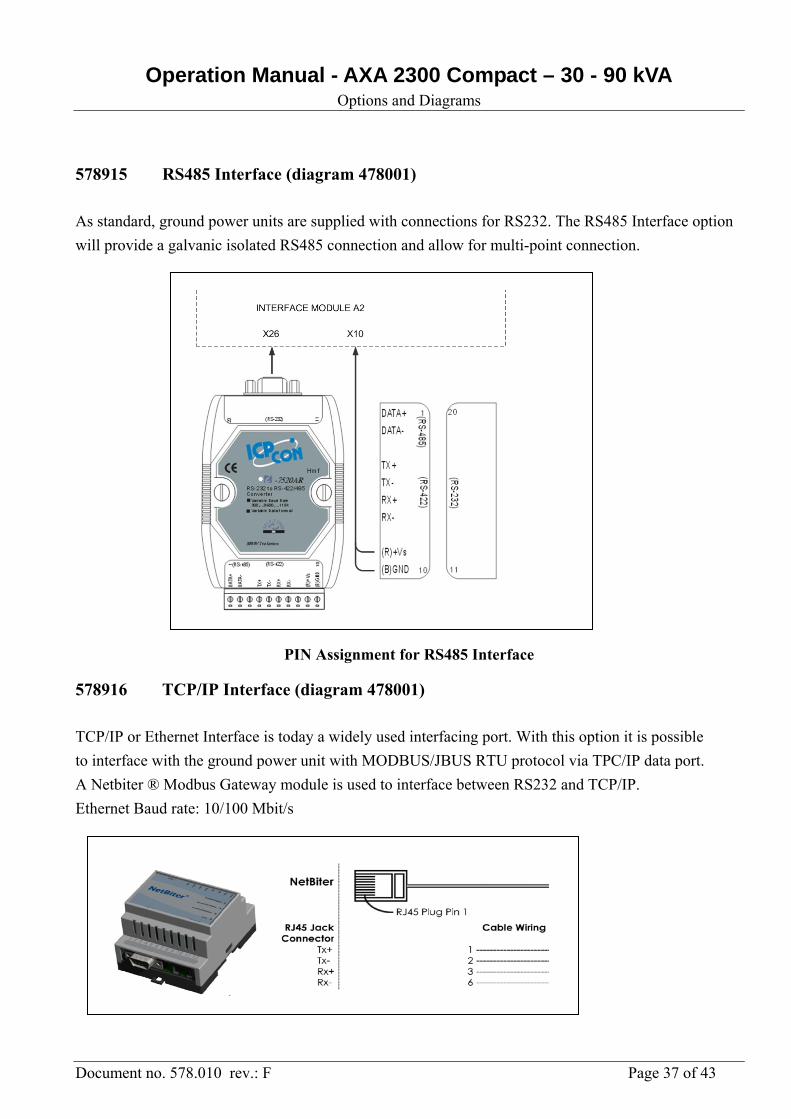
578915 RS485 Interface (diagram 478001)
As standard, ground power units are supplied with connections for RS232. The RS485 Interface option
will provide a galvanic isolated RS485 connection and allow for multi-point connection.
PIN Assignment for RS485 Interface
578916 TCP/IP Interface (diagram 478001)
TCP/IP or Ethernet Interface is today a widely used interfacing port. With this option it is possible
to interface with the ground power unit with MODBUS/JBUS RTU protocol via TPC/IP data port.
A Netbiter ® Modbus Gateway module is used to interface between RS232 and TCP/IP.
Ethernet Baud rate: 10/100 Mbit/s
Operation Manual - AXA 2300 Compact – 30 - 90 kVA Options and Diagrams
Document no. 578.010 rev.: F Page 38 of 43
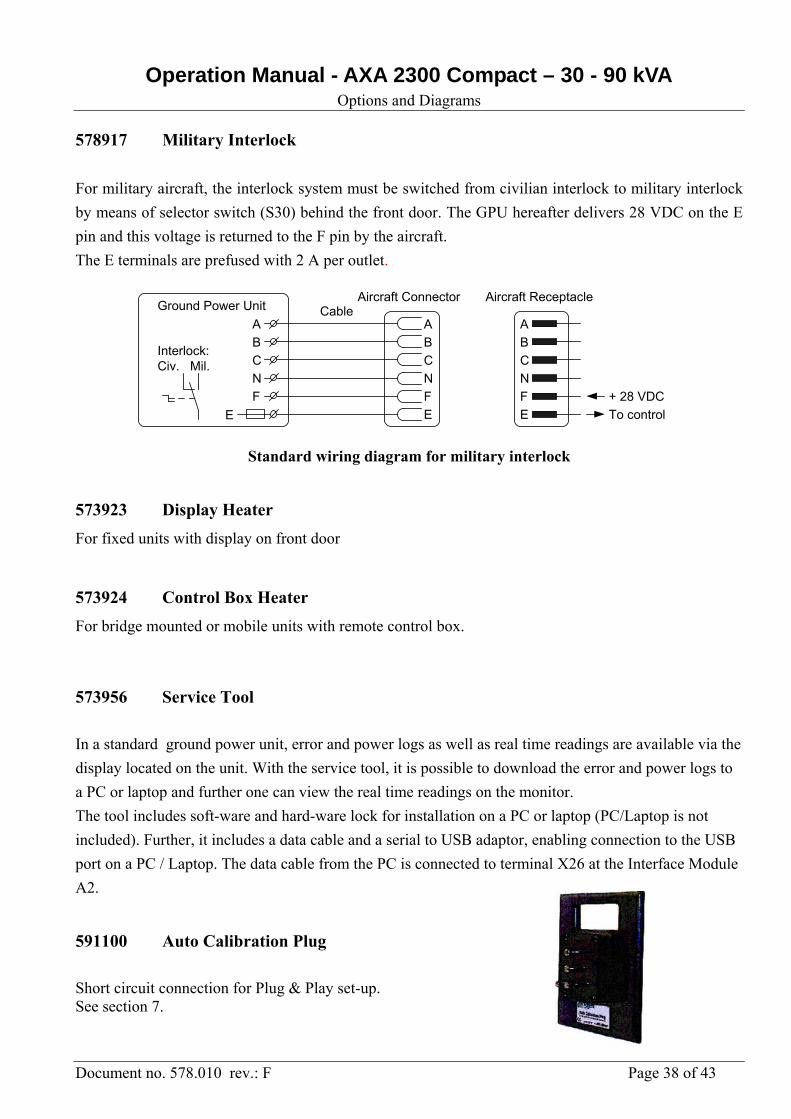
578917 Military Interlock
For military aircraft, the interlock system must be switched from civilian interlock to military interlock
by means of selector switch (S30) behind the front door. The GPU hereafter delivers 28 VDC on the E
pin and this voltage is returned to the F pin by the aircraft.
The E terminals are prefused with 2 A per outlet.
A
B
C
N
F
E
A
B
C
N
F
E
+ 28 VDC
To control
Aircraft ReceptacleAircraft ConnectorGround Power Unit Cable
A
B
C
N
F
E
Interlock:Civ. Mil.
Standard wiring diagram for military interlock
573923 Display Heater
For fixed units with display on front door
573924 Control Box Heater
For bridge mounted or mobile units with remote control box.
573956 Service Tool
In a standard ground power unit, error and power logs as well as real time readings are available via the
display located on the unit. With the service tool, it is possible to download the error and power logs to
a PC or laptop and further one can view the real time readings on the monitor.
The tool includes soft-ware and hard-ware lock for installation on a PC or laptop (PC/Laptop is not
included). Further, it includes a data cable and a serial to USB adaptor, enabling connection to the USB
port on a PC / Laptop. The data cable from the PC is connected to terminal X26 at the Interface Module
A2.
591100 Auto Calibration Plug
Short circuit connection for Plug & Play set-up. See section 7.
Operation Manual - AXA 2300 Compact – 30 - 90 kVA For GPUs with 28 VDC Transformer Rectifier
Document no. 578.010 rev.: F Page 39 of 43
12.0 For units equipped with 28 VDC outlet
12.1 General Description
All AXA2300 units from 30 kVA to 90 kVA can be equipped with a 28 VDC output.
As the 28 VDC part is supplied from the 400 Hz output, simultaneous use of the 400 Hz and the
28 VDC outlets is not possible.
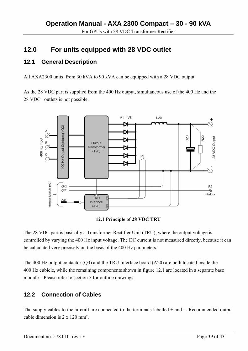
12.1 Principle of 28 VDC TRU
The 28 VDC part is basically a Transformer Rectifier Unit (TRU), where the output voltage is
controlled by varying the 400 Hz input voltage. The DC current is not measured directly, because it can
be calculated very precisely on the basis of the 400 Hz parameters.
The 400 Hz output contactor (Q3) and the TRU Interface board (A20) are both located inside the
400 Hz cubicle, while the remaining components shown in figure 12.1 are located in a separate base
module – Please refer to section 5 for outline drawings.
12.2 Connection of Cables
The supply cables to the aircraft are connected to the terminals labelled + and –. Recommended output
cable dimension is 2 x 120 mm².
Operation Manual - AXA 2300 Compact – 30 - 90 kVA For GPUs with 28 VDC Transformer Rectifier
Document no. 578.010 rev.: F Page 40 of 43
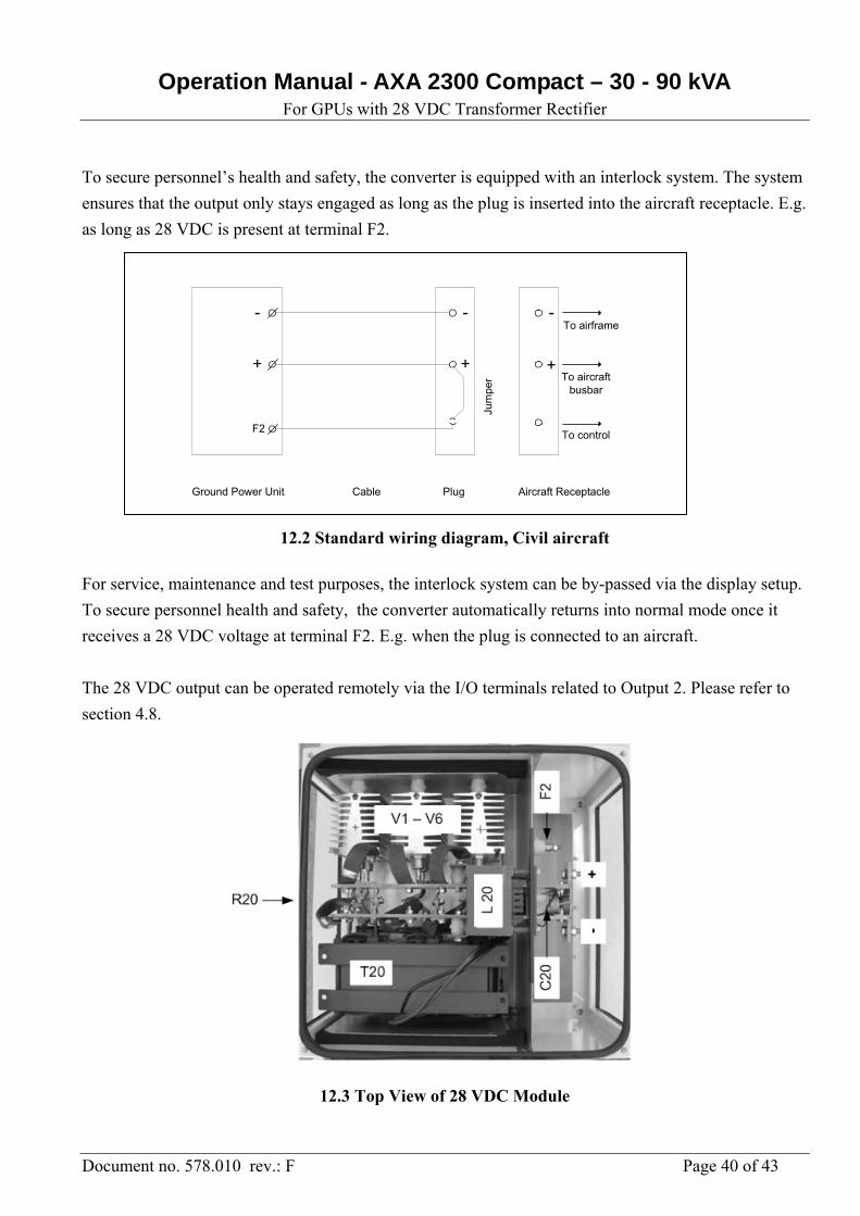
To secure personnel’s health and safety, the converter is equipped with an interlock system. The system
ensures that the output only stays engaged as long as the plug is inserted into the aircraft receptacle. E.g.
as long as 28 VDC is present at terminal F2.
-
+
F2
Ground Power Unit Cable Plug Aircraft ReceptacleJu
mpe
r
To control
-
+
-
+To aircraft
busbar
To airframe
12.2 Standard wiring diagram, Civil aircraft
For service, maintenance and test purposes, the interlock system can be by-passed via the display setup.
To secure personnel health and safety, the converter automatically returns into normal mode once it
receives a 28 VDC voltage at terminal F2. E.g. when the plug is connected to an aircraft.
The 28 VDC output can be operated remotely via the I/O terminals related to Output 2. Please refer to
section 4.8.
12.3 Top View of 28 VDC Module
Operation Manual - AXA 2300 Compact – 30 - 90 kVA For GPUs with 28 VDC Transformer Rectifier
Document no. 578.010 rev.: F Page 41 of 43
12.3 Operator’s Instruction
The 28 VDC is controlled by means of the Display / Keyboard Interface – Please refer to section 6.
To adapt the converter to different types of aircraft, it is possible to set a maximum DC current level in
steps of 300 Amp. (e.g. 600, 900, 1200, 1500, 1800, 2100 and 2400 Amp). To do so, use the arrow push
buttons at the keyboard. To ensure hassle-free starting of the aircraft engine, the current limit function is
delayed 0,7 seconds.
12.4 Setup of Parameters
Further to the parameters that can be viewed and changed according to section 7, it is possible to adjust
the output voltage and the cable compensation of converters equipped with 28 VDC output. To adjust
the cable compensation:
1. Apply nominal load by means of a load bank.
2. Select “DC CABLE COMPENSATION” via the Setup Mode.
3. Adjust the compensation by means of the vertical arrow buttons at the display keyboard, until
the voltage at the aircraft connector equals the no load voltage.
Operation Manual - AXA 2300 Compact – 30 - 90 kVA For GPUs with 28 VDC Transformer Rectifier
Document no. 578.010 rev.: F Page 42 of 43
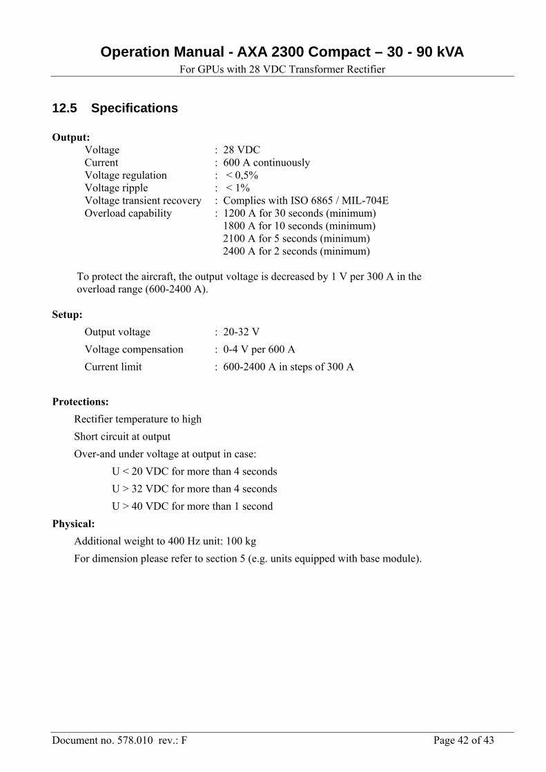
12.5 Specifications Output: Voltage : 28 VDC Current : 600 A continuously Voltage regulation : < 0,5% Voltage ripple : < 1% Voltage transient recovery : Complies with ISO 6865 / MIL-704E Overload capability : 1200 A for 30 seconds (minimum) 1800 A for 10 seconds (minimum) 2100 A for 5 seconds (minimum) 2400 A for 2 seconds (minimum) To protect the aircraft, the output voltage is decreased by 1 V per 300 A in the overload range (600-2400 A). Setup:
Output voltage : 20-32 V
Voltage compensation : 0-4 V per 600 A
Current limit : 600-2400 A in steps of 300 A
Protections:
Rectifier temperature to high
Short circuit at output
Over-and under voltage at output in case:
U < 20 VDC for more than 4 seconds
U > 32 VDC for more than 4 seconds
U > 40 VDC for more than 1 second
Physical:
Additional weight to 400 Hz unit: 100 kg
For dimension please refer to section 5 (e.g. units equipped with base module).
Operation Manual - AXA 2300 Compact – 30 - 90 kVA For GPUs with 28 VDC Transformer Rectifier
Document no. 578.010 rev.: F Page 43 of 43
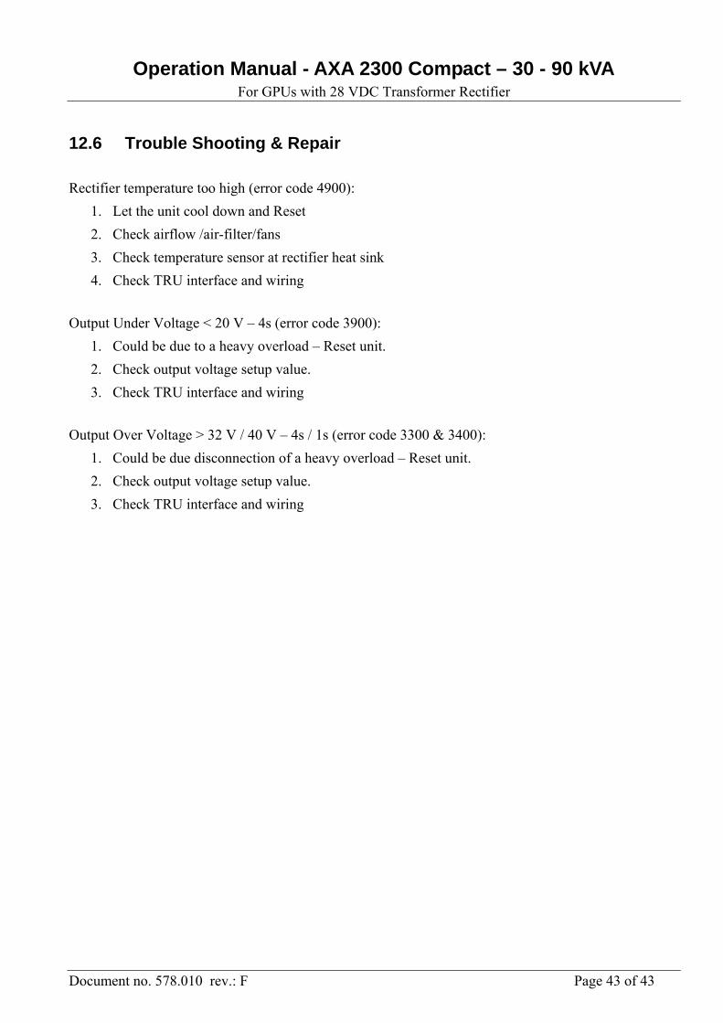
12.6 Trouble Shooting & Repair
Rectifier temperature too high (error code 4900):
1. Let the unit cool down and Reset
2. Check airflow /air-filter/fans
3. Check temperature sensor at rectifier heat sink
4. Check TRU interface and wiring
Output Under Voltage < 20 V – 4s (error code 3900):
1. Could be due to a heavy overload – Reset unit.
2. Check output voltage setup value.
3. Check TRU interface and wiring
Output Over Voltage > 32 V / 40 V – 4s / 1s (error code 3300 & 3400):
1. Could be due disconnection of a heavy overload – Reset unit.
2. Check output voltage setup value.
3. Check TRU interface and wiring


![Axa Magnet - Presentasi AXA Magnet [ Maestro Global Network ] Terbaru](https://img.pdfslide.net/doc/110x75/55d2ed27bb61ebdd398b462f/axa-magnet-presentasi-axa-magnet-maestro-global-network-terbaru.jpg)
