Embed Size (px)
Citation preview

Victron Energy bv / De Paal 35 / 1351 JG ALMERE / The NetherlandsPhone: (+31) (0)36 535 97 00 / Fax:
BMS12/200 ENGLISH
1. Mount the BMS preferably on a vertical surface, for optimal
cooling. 2. Determine the rating of fuse AB (see figure and table 1)
The fuse on input AB doubles as a shunt. The BMS will limit the input current according to the rating of this fuse. For fuse and corresponding current limit please see table Choosing the right fuse will prevent overheating of the alternator and/or DC cabling.
3. Determine the rating of fuse LB (see figure). This fuse should be rated in accordance with the expected load current and the cross section of the cabling to the load.
4. Disconnect the cabling from the plus pole of the starter battery.5. Pull off the REMOTE on/off connector to prevent unwanted
switching of the BMS. 6. Install and connect all electrical cabling and fuses AB,
leave the plus poles of the Li-ion batteries and stardisconnected.
7. Daisy-chain the battery control cables between the and connect to the BMS.
8. Connect the plus cabling to the Li-ion batteries andbattery.
9. Reinsert the REMOTE on/off connector on the BMS. The BMS is now ready for use. Notes: a) A battery charger can be connected to input AB instea
alternator. b) The Li-ion batteries can be charged as well as discharged t
input/output LB. c) When a load with a large electrolytic capacitor bank
inverter or inverter/charger rated at 1200VA or more) to LB, the BMS will limit its average output current during startto approximately 80A. Therefore the capacity to simultaneously start-up other DC loads is limited to 80A. Once the capacitor bank is fully charged, the current limit increases to 400A.
Up to ten 12,8V LFP batteries can be connected in parallel
AB
If the required charge current (input AB) is less than 40 A, please use this ATO fuse holder
Victron Energy bv / De Paal 35 / 1351 JG ALMERE / The Netherlandsax: (+31) (0)36 535 97 40 / www.victronenergy.com / e-mail: s
Mount the BMS preferably on a vertical surface, for optimal
and table 1). shunt. The BMS will limit the
. For fuse ratings 1.
Choosing the right fuse will prevent overheating of the alternator
This fuse should be rated in accordance with the expected load current and the cross section of the cabling to the load. Disconnect the cabling from the plus pole of the starter battery.
off connector to prevent unwanted
and fuses AB, LB, but ion batteries and starter battery
the Li-ion batteries
and the starter
on the BMS.
A battery charger can be connected to input AB instead of the
charged as well as discharged through
When a load with a large electrolytic capacitor bank (such as an inverter or inverter/charger rated at 1200VA or more) is connected
output current during start-up . Therefore the capacity to simultaneously
up other DC loads is limited to 80A. Once the capacitor bank is fully charged, the current limit increases to 400A.
BMS 12/200 specificationMaximum number of 12,8V batteries Maximum charge current, Power Port ABMaximum charge current, Power Port LBMaximum continuous discharge current, LB
Peak discharge current, LB (short circuit proof)Approximate cut-off voltage
GENERAL No load current when operating Current consumption when switched offCurrent consumption after battery discharge cut-off due to low cell voltage Operating temperature range
Humidity, maximum Humidity, average Protection, electronics DC connection AB, LB and battery minusDC connection battery plus
LED’s Battery being charged through Power Port ABBattery being charged through Power Port LBPower port LB active Over temperature
ENCLOSURE Weight (kg) Dimensions (hxwxd in mm)
STANDARDS Emission Immunity
Automotive Directive
Up to ten 12,8V LFP batteries can be connected in parallel
Isolated Orion DC-DC converter needed for DC loads with minus connected to chassis
LB
Table 1
Fuse AB Max. charge current
100 A
80 A
60 A
2 x 30 A
2 x 20 A
2 x 15 A
2 x 10 A
2 x 7,5 A
Victron Energy bv / De Paal 35 / 1351 JG ALMERE / The Netherlands il: [email protected]
specification 10
Maximum charge current, Power Port AB 80A @ 40°C
Maximum charge current, Power Port LB 200A @ 40°C
Maximum continuous discharge current, LB 200A @ 40°C
B (short circuit proof) 400A 11V
10mA Current consumption when switched off 5mA Current consumption after battery discharge 3mA
-40 to +60°C
100% 95% IP65
DC connection AB, LB and battery minus M8 Faston female
6.3 mm
Battery being charged through Power Port AB green ery being charged through Power Port LB green
green red
1,8
65 x 120 x 260
EN 50081-1
EN 50082-1
2004/104/EC
DC converter th minus
Revision : Rev 02 Date : 31-05-2013
Max. charge current
90 A
70 A
40 A
35 A
25 A
20 A
18 A
12 A

Victron Energy bv / De Paal 35 / 1351 JG ALMERE / The NetherlandsPhone: (+31) (0)36 535 97 00 / Fax:
BMS12/200 NEDERLANDS
1. Monteer het BMS bij voorkeur op een verticaal oppervlak voor
optimale koeling. 2. Bepaal het stroombereik van zekering AB (zie afbeelding en tabel
1). Deze zekering bij ingang AB fungeert tevens als shunt. Het BMS beperkt de ingangsstroom overeenkomstig met het stroombereik van deze zekering. Zie tabel 1 voor stroombereiken van zekeringen en de bijbehorende stroomlimiet. Met de keuze voor de juiste zekering wordt oververhitting van de dynamo en/of DC-bekabeling voorkomen.
3. Het stroombereik van zekering LB bepalen (zie afbeelding).Deze zekering moet een stroombereik hebben dat overeenstemt met de verwachte laadstroom en de diameter van de bekabeling naar de belasting.
4. Ontkoppel de bekabeling van de pluspool van de startaccu.5. Verwijder de aansluiting van aan/uit OP AFSTAND om ongewenst
schakelen van het BMS te voorkomen. 6. Installeer en verbind alle elektrische bekabeling en de zekeringen
AB en LB, maar laat de pluspolen van de Li-ion accu's en startaccu ontkoppeld.
7. Schakel de accubesturingskabels in een keten tussen de Liaccu's en sluit ze aan op het BMS.
8. Sluit de plusbekabeling aan op de Li-ion accu's en de startaccu.9. Plaats de aansluiting van aan/uit OP AFSTAND weer in het BMS. Het BMS is nu klaar voor gebruik. Opmerkingen: a) Een acculader kan worden aangesloten op ingang AB in plaats
van op de dynamo. b) De Li-ion accu's kunnen zowel geladen als ontladen worden via
ingang/uitgang LB. c) Wanneer een belasting met een grote bank elektrolytische
condensatoren (zoals een omvormer of omvormer/lader met een stroombereik van 1200 VA of groter) op LB wordt aangesloten, zal het BMS de gemiddelde uitgangsstroom tijdens het opstarten tot ongeveer 80 A beperken. Hierdoor is de capaciteit om belastingen tegelijk op te starten beperkt tot 80 A. Wanneer de condensatorbank volledig geladen is, is de stroomlimiet toegenomen tot 400 A.
Tabel 1
AB
Als de vereiste laadstroom (ingang AB) minder dan 40 A is, moet u deze ATOzekeringhouder gebruiken
Tot tien 12,8 V LFPparallel worden geschakeld
Victron Energy bv / De Paal 35 / 1351 JG ALMERE / The Netherlandsax: (+31) (0)36 535 97 40 / www.victronenergy.com / e-mail: s
Monteer het BMS bij voorkeur op een verticaal oppervlak voor
Bepaal het stroombereik van zekering AB (zie afbeelding en tabel
Deze zekering bij ingang AB fungeert tevens als shunt. Het BMS het stroombereik
van deze zekering. Zie tabel 1 voor stroombereiken van
Met de keuze voor de juiste zekering wordt oververhitting van de
ring LB bepalen (zie afbeelding). Deze zekering moet een stroombereik hebben dat overeenstemt met de verwachte laadstroom en de diameter van de bekabeling
Ontkoppel de bekabeling van de pluspool van de startaccu. Verwijder de aansluiting van aan/uit OP AFSTAND om ongewenst
Installeer en verbind alle elektrische bekabeling en de zekeringen ion accu's en
accubesturingskabels in een keten tussen de Li-ion
ion accu's en de startaccu. Plaats de aansluiting van aan/uit OP AFSTAND weer in het BMS.
Een acculader kan worden aangesloten op ingang AB in plaats
ion accu's kunnen zowel geladen als ontladen worden via
lektrolytische condensatoren (zoals een omvormer of omvormer/lader met een stroombereik van 1200 VA of groter) op LB wordt aangesloten, zal het BMS de gemiddelde uitgangsstroom tijdens het opstarten tot ongeveer 80 A beperken. Hierdoor is de capaciteit om andere DC-belastingen tegelijk op te starten beperkt tot 80 A. Wanneer de condensatorbank volledig geladen is, is de stroomlimiet
Zekering AB Max. laadstroom
100 A
80 A
60 A
2 x 30 A
2 x 20 A
2 x 15 A
2 x 10 A
2 x 7,5 A
Specificaties BMS 12/200Maximumaantal 12,8 V accu's Maximum laadstroom, Power Port AB Maximum laadstroom, Power Port LB Maximum continue ontlaadstroom, LB Piekontlading/-stroom, LB (beveiligd tegen kortsluiting) Afslagspanning bij benadering
ALGEMEEN Nullaststroom Stroomverbruik wanneer uitgeschakeld Stroomverbruik nadat ontlading accu is gestopt als gevolg van lage cel spanningBedrijfstemperatuurbereik Vochtigheidsgraad, maximum Vochtigheidsgraad, gemiddeld Beschermingsgraad van de electronica DC-aansluiting AB, LB en minpool accu DC-aansluiting pluspool accu
LED’s Accu wordt geladen via Power Port AB Accu wordt geladen via Power Port LB Power port LB actief Temperatuur te hoog
BEHUIZING Gewicht (kg) Afmetingen (hxbxd in mm)
NORMEN Emissie
Immuniteit Voertuigrichtlijn
LB
Als de vereiste laadstroom (ingang AB) s, moet u deze ATO-
zekeringhouder gebruiken.
en 12,8 V LFP-accu's kunnen parallel worden geschakeld
Geïsoleerde Orion DC/DC omvormer nodig voor gelijkstroombelastingen als minpool verbonden is met chassis
Victron Energy bv / De Paal 35 / 1351 JG ALMERE / The Netherlands il: [email protected]
Max. laadstroom
90 A
70 A
40 A
35 A
25 A
20 A
18 A
12 A
Specificaties BMS 12/200 10
80 A bij 40 °C 200A bij 40 °C 200A bij 40 °C
stroom, LB (beveiligd tegen 400A
11V
10mA 5mA
gestopt als gevolg van lage cel spanning 3 mA
-40 tot +60 °C 100% 95% IP 65 M8
Vrouwelijke faston 6,3 mm
groen groen groen rood
1,8 65 x 120 x 260
EN 50081-1
EN 50082-1
2004/104/EG
Geïsoleerde Orion DC/DC omvormer nodig voor gelijkstroombelastingen als
Victron Energy bv / De Paal 35 / 1351 JG ALMERE / The NetherlandsPhone: (+31) (0)36 535 97 00 / Fax:
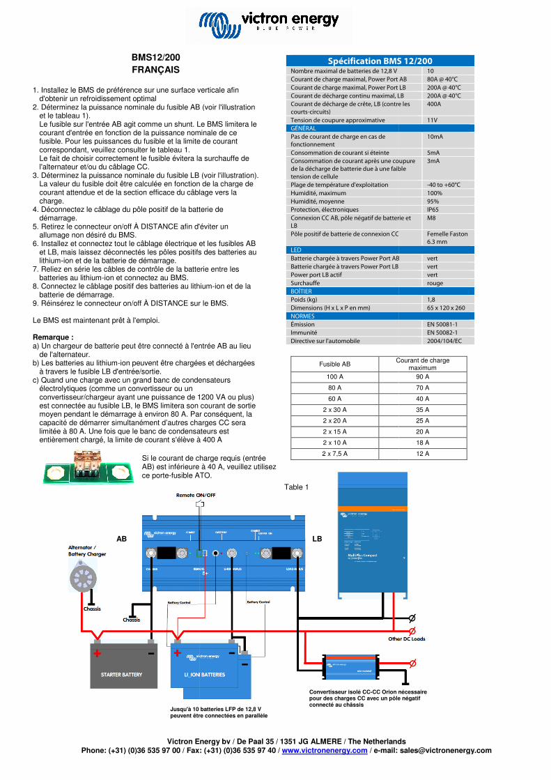
BMS12/200 FRANÇAIS
1. Installez le BMS de préférence sur une surface verticale afin d'obtenir un refroidissement optimal
2. Déterminez la puissance nominale du fusible AB (voir l'illustration et le tableau 1). Le fusible sur l'entrée AB agit comme un shunt. Le BMS limitera le courant d'entrée en fonction de la puissance nominale de ce fusible. Pour les puissances du fusible et la limite de courant correspondant, veuillez consulter le tableau 1. Le fait de choisir correctement le fusible évitera la surchauffe de l'alternateur et/ou du câblage CC.
3. Déterminez la puissance nominale du fusible LB (voir l'illLa valeur du fusible doit être calculée en fonction de la charge de courant attendue et de la section efficace du câblage vers la charge.
4. Déconnectez le câblage du pôle positif de la batterie de démarrage.
5. Retirez le connecteur on/off À DISTANCE afin d'éviter un allumage non désiré du BMS.
6. Installez et connectez tout le câblage électrique et les fusibles AB et LB, mais laissez déconnectés les pôles positifs des batteries au lithium-ion et de la batterie de démarrage.
7. Reliez en série les câbles de contrôle de la batterie entre les batteries au lithium-ion et connectez au BMS.
8. Connectez le câblage positif des batteries au lithiumbatterie de démarrage.
9. Réinsérez le connecteur on/off À DISTANCE sur le BMS. Le BMS est maintenant prêt à l'emploi. Remarque : a) Un chargeur de batterie peut être connecté à l'entrée AB au lieu
de l'alternateur. b) Les batteries au lithium-ion peuvent être chargées et déchargées
à travers le fusible LB d'entrée/sortie. c) Quand une charge avec un grand banc de condensateurs
électrolytiques (comme un convertisseur ou un convertisseur/chargeur ayant une puissance de 1200est connectée au fusible LB, le BMS limitera son courant de sortie moyen pendant le démarrage à environ 80 A. Par conséquent, la capacité de démarrer simultanément d’autres charges CC sera limitée à 80 A. Une fois que le banc de condensateurs est entièrement chargé, la limite de courant s'élève à 400
Jusqu'à 10 batteries LFP de 12,8peuvent être connectées en parallèle
AB
Si le courant de charge requis (entrée AB) est inférieure à 40ce porte-fusible ATO.
Victron Energy bv / De Paal 35 / 1351 JG ALMERE / The Netherlandsax: (+31) (0)36 535 97 40 / www.victronenergy.com / e-mail: s
Installez le BMS de préférence sur une surface verticale afin
Déterminez la puissance nominale du fusible AB (voir l'illustration
Le fusible sur l'entrée AB agit comme un shunt. Le BMS limitera le courant d'entrée en fonction de la puissance nominale de ce
puissances du fusible et la limite de courant
Le fait de choisir correctement le fusible évitera la surchauffe de
Déterminez la puissance nominale du fusible LB (voir l'illustration). La valeur du fusible doit être calculée en fonction de la charge de courant attendue et de la section efficace du câblage vers la
Déconnectez le câblage du pôle positif de la batterie de
Retirez le connecteur on/off À DISTANCE afin d'éviter un
Installez et connectez tout le câblage électrique et les fusibles AB et LB, mais laissez déconnectés les pôles positifs des batteries au
Reliez en série les câbles de contrôle de la batterie entre les
Connectez le câblage positif des batteries au lithium-ion et de la
Réinsérez le connecteur on/off À DISTANCE sur le BMS.
Un chargeur de batterie peut être connecté à l'entrée AB au lieu
es et déchargées
Quand une charge avec un grand banc de condensateurs
convertisseur/chargeur ayant une puissance de 1200 VA ou plus) limitera son courant de sortie
A. Par conséquent, la capacité de démarrer simultanément d’autres charges CC sera
A. Une fois que le banc de condensateurs est ève à 400 A
Spécification BMS 12/200Nombre maximal de batteries de 12,8 V Courant de charge maximal, Power Port ABCourant de charge maximal, Power Port LBCourant de décharge continu maximal, LBCourant de décharge de crête, LB (contre les courts-circuits) Tension de coupure approximative GÉNÉRAL Pas de courant de charge en cas de fonctionnement Consommation de courant si éteinte Consommation de courant après une coupure de la décharge de batterie due à une faible tension de cellule Plage de température d'exploitation Humidité, maximum Humidité, moyenne Protection, électroniques Connexion CC AB, pôle négatif de batterie et LB Pôle positif de batterie de connexion CC
LED Batterie chargée à travers Power Port ABBatterie chargée à travers Power Port LB Power port LB actif Surchauffe BOÎTIER Poids (kg) Dimensions (H x L x P en mm) NORMES Émission Immunité Directive sur l'automobile
Fusible AB Courant de charge
100 A
80 A
60 A
2 x 30 A
2 x 20 A
2 x 15 A
2 x 10 A
2 x 7,5 A
Jusqu'à 10 batteries LFP de 12,8 V peuvent être connectées en parallèle
Convertisseur isolé CC-CC Orion nécessaire pour des charges CC avec un pôle négatif connecté au châssis
LB
Table 1
Si le courant de charge requis (entrée AB) est inférieure à 40 A, veuillez utilisez
fusible ATO.
Victron Energy bv / De Paal 35 / 1351 JG ALMERE / The Netherlands il: [email protected]
Spécification BMS 12/200 10
Courant de charge maximal, Power Port AB 80A @ 40°C Courant de charge maximal, Power Port LB 200A @ 40°C
harge continu maximal, LB 200A @ 40°C Courant de décharge de crête, LB (contre les 400A
11V
10mA
5mA mation de courant après une coupure
de la décharge de batterie due à une faible 3mA
-40 to +60°C 100% 95% IP65
égatif de batterie et M8
Pôle positif de batterie de connexion CC Femelle Faston 6.3 mm
Batterie chargée à travers Power Port AB vert vert
vert rouge
1,8 65 x 120 x 260
EN 50081-1 EN 50082-1 2004/104/EC
Courant de charge maximum
90 A
70 A
40 A
35 A
25 A
20 A
18 A
12 A
CC Orion nécessaire pour des charges CC avec un pôle négatif
Victron Energy bv / De Paal 35 / 1351 JG ALMERE / The NetherlandsPhone: (+31) (0)36 535 97 00 / Fax:
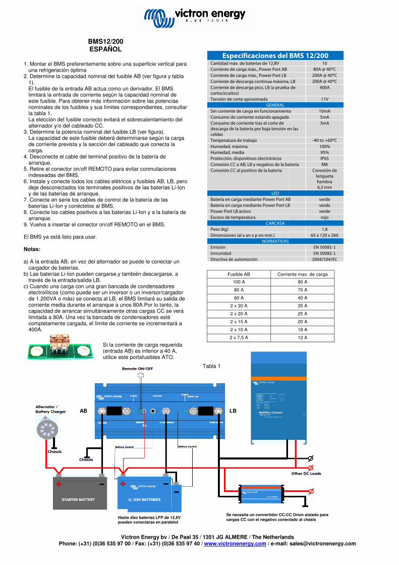
BMS12/200 ESPAÑOL
1. Montar el BMS preferentemente sobre una superficie vertical para
una refrigeración óptima 2. Determine la capacidad nominal del fusible AB (ver figura y tabla
1). El fusible de la entrada AB actua como un derivador. El limitará la entrada de corriente según la capacidad nominal de este fusible. Para obtener más información sobre las potencias nominales de los fusibles y sus límites correspondientes, consultar la tabla 1. La elección del fusible correcto evitará el sobrecalentamiento del alternador y/o del cableado CC.
3. Determine la potencia nominal del fusible LB (ver figura).La capacidad de este fusible deberá determinarse según la carga de corriente prevista y la sección del cableado que conecta la carga.
4. Desconecte el cable del terminal positivo de la batería de arranque.
5. Retire el conector on/off REMOTO para evitar conmutaciones indeseadas del BMS.
6. Instale y conecte todos los cables elétricos y fusibles AB, LB, pero deje desconectados los terminales positivos de las baterías Liy de las baterías de arranque.
7. Conecte en serie los cables de control de la batería de las baterías Li-Ion y conéctelos al BMS.
8. Conecte los cables positivos a las baterías Li-Ion y a la bateríaarranque.
9. Vuelva a insertar el conector on/off REMOTO en el BMS. El BMS ya está listo para usar. Notas: a) A la entrada AB, en vez del alternador se puede le conectar un
cargador de baterías. b) Las baterías Li-Ion pueden cargarse,y también descargarse, a
través de la entrada/salida LB. c) Cuando una carga con una gran bancada de condensadores
electrolíticos (como puede ser un inversor o un inversor/cargador de 1.200VA o más) se conecta al LB, el BMS limitará su salida de corriente media durante el arranque a unos 80A.Por lo tanto, la capacidad de arrancar simultáneamente otras cargas CC se verá limitada a 80A. Una vez la bancada de condensadores esté completamente cargada, el límite de corriente se incrementará a 400A.
Hasta diez baterías LFP de 12,8V pueden conectarse en paralelol
Si la corriente de car(entrada AB) es inferior a 40 A, utilice este portafusibles ATO
AB
Victron Energy bv / De Paal 35 / 1351 JG ALMERE / The Netherlandsax: (+31) (0)36 535 97 40 / www.victronenergy.com / e-mail: s
re una superficie vertical para
Determine la capacidad nominal del fusible AB (ver figura y tabla
El fusible de la entrada AB actua como un derivador. El BMS limitará la entrada de corriente según la capacidad nominal de este fusible. Para obtener más información sobre las potencias nominales de los fusibles y sus límites correspondientes, consultar
brecalentamiento del
Determine la potencia nominal del fusible LB (ver figura). La capacidad de este fusible deberá determinarse según la carga de corriente prevista y la sección del cableado que conecta la
el cable del terminal positivo de la batería de
Retire el conector on/off REMOTO para evitar conmutaciones
Instale y conecte todos los cables elétricos y fusibles AB, LB, pero desconectados los terminales positivos de las baterías Li-Ion
Conecte en serie los cables de control de la batería de las
Ion y a la batería de
Vuelva a insertar el conector on/off REMOTO en el BMS.
A la entrada AB, en vez del alternador se puede le conectar un
Ion pueden cargarse,y también descargarse, a
Cuando una carga con una gran bancada de condensadores electrolíticos (como puede ser un inversor o un inversor/cargador
BMS limitará su salida de corriente media durante el arranque a unos 80A.Por lo tanto, la capacidad de arrancar simultáneamente otras cargas CC se verá limitada a 80A. Una vez la bancada de condensadores esté
se incrementará a
Especificaciones del BMS 12/200Cantidad máx. de baterías de 12,8V Corriente de carga máx., Power Port AB
Corriente de carga máx., Power Port LB Corriente de descarga continua máxima, LBCorriente de descarga pico, LB (a prueba de cortocircuitos) Tensión de corte aproximada
GENERAL Sin corriente de carga en funcionamientoConsumo de corriente estando apagadaConsumo de corriente tras el corte de descarga de la batería por baja tensión en las celdas Temperatura de trabajo
Humedad, máxima Humedad, media Protección, dispositivos electrónicos Conexión CC a AB, LB y negativo de la bateríaConexión CC al positivo de la batería
LED Batería en carga mediante Power Port ABBatería en carga mediante Power Port LBPower Port LB activo Exceso de temperatura
CARCASA Peso (kg) Dimensiones (al x an x p en mm.)
NORMATIVASEmisión
Inmunidad Directiva de automoción
Tabla 1
Hasta diez baterías LFP de 12,8V pueden conectarse en paralelol
Se necesita un convertidor CC-CC Orion aislado para cargas CC con el negativo conectado al chasis
Si la corriente de carga requerida (entrada AB) es inferior a 40 A, utilice este portafusibles ATO.
LB
Fusible AB Corriente max. de carga
100 A
80 A
60 A
2 x 30 A
2 x 20 A
2 x 15 A
2 x 10 A
2 x 7,5 A
Victron Energy bv / De Paal 35 / 1351 JG ALMERE / The Netherlands il: [email protected]
Especificaciones del BMS 12/200 10
80A @ 40°C
200A @ 40°C
Corriente de descarga continua máxima, LB 200A @ 40°C
Corriente de descarga pico, LB (a prueba de 400A
11V
Sin corriente de carga en funcionamiento 10mA Consumo de corriente estando apagada 5mA
descarga de la batería por baja tensión en las 3mA
-40 to +60°C
100% 95% IP65
la batería M8 Conexión de lengueta hembra 6,3 mm
Batería en carga mediante Power Port AB verde Batería en carga mediante Power Port LB verde
verde rojo
1,8 65 x 120 x 260
NORMATIVAS EN 50081-1
EN 50082-1
2004/104/EC
CC Orion aislado para cargas CC con el negativo conectado al chasis
Corriente max. de carga
90 A
70 A
40 A
35 A
25 A
20 A
18 A
12 A

Victron Energy bv / De Paal 35 / 1351 JG ALMERE / The NetherlandsPhone: (+31) (0)36 535 97 00 / Fax:
BMS12/200 DEUTSCH
1. Montieren Sie den BMS für eine optimale Kühlung am Besten an
einer vertikalen Oberfläche. 2. Bestimmen Sie den Nennwert der AB-Sicherung (siehe Abbildung
und Tabelle 1). Die Sicherung am Eingang AB verdoppelt sich als Shunt. Der BMS wird den Eingangsstrom entsprechend dem Nennwert dieser Sicherung begrenzen. Die Nennwerte der Sicherungen und die entsprechenden Strombegrenzungen entnehmen Sie bitte der Tabelle 1. Die Wahl der richtigen Sicherung verhindert ein Überhitzen des Wechselstromgenerators und/oder der DC-Verkabelung.
3. Bestimmen Sie den Nennwert der LB-Sicherung (sieheDer Nennwert dieser Sicherung ist in Einklang mit der zu erwartenden Strombelastung und dem Durchschnitt der Verkabelung zur Last zu wählen.
4. Trennen Sie die Verkabelung vom Plus-Pol der Starter5. Trennen Sie den Stecker für den FERNGESTEUERTEN Ein
Schalter, um ein versehentliches Einschalten des BMS zuverhindern.
6. Installieren und verbinden Sie sämtliche elektrischen Verkabelungen und die AB- und LB- Sicherungen. Schließen Sie jedoch die Plus-Pole der Lithium-Ionen-Batterien und der StarterBatterie noch nicht an.
7. Verketten Sie die Batteriesteuerungskabel zwischen den LithiumIonen-Batterien und schließen Sie den BMS an.
8. Verbinden Sie die Plus-Verkabelung mit den LithiumBatterien und der Starter-Batterie.
9. Verbinden Sie den Stecker für den FERNGESTEUERTEN Ein/Aus-Schalter wieder mit dem BMS.
Der BMS ist nun einsatzbereit. Beachte: a) Anstatt des Wechselstromgenerators lässt sich auch ein Batterie
Ladegerät an Eingang AB anschließen. b) Die Lithium-Ionen-Batterien lassen sich über den LBc) Eingang/Ausgang laden und entladen. d) Wenn eine Last mit einer großen Elektrolytkondensatorbank (wie
z. B. ein Wechselrichter oder Wechselrichter/Ladegerät mit einem Nennwert von 1200 VA oder mehr) an LB angeschlossen ist, begrenzt der BMS seine durchschnittliche Ausgangsleistung während des Einschaltens auf ungefähr 80 A. Aus diesem Grund wird die Kapazität zum Einschalten anderer DC-Lasten auf 80begrenzt. Nachdem die Kondensatorbank voll aufgeladen ist, steigt die Strombegrenzung auf 400 A an.
Es lassen sich bis zu zehn 12,Batterien parallel schalten.
AB
Wenn der erforderliche Ladestrom (Eingang AB) geringer als 40verwenden Sie bitte diese ATO Sicherungsfassung.
Victron Energy bv / De Paal 35 / 1351 JG ALMERE / The Netherlandsax: (+31) (0)36 535 97 40 / www.victronenergy.com / e-mail: s
Montieren Sie den BMS für eine optimale Kühlung am Besten an
Sicherung (siehe Abbildung
ppelt sich als Shunt. Der BMS wird den Eingangsstrom entsprechend dem Nennwert dieser Sicherung begrenzen. Die Nennwerte der Sicherungen und die entsprechenden Strombegrenzungen entnehmen Sie bitte der
ein Überhitzen des Verkabelung.
Sicherung (sieheAbbildung). Der Nennwert dieser Sicherung ist in Einklang mit der zu erwartenden Strombelastung und dem Durchschnitt der
Pol der Starter-Batterie. ür den FERNGESTEUERTEN Ein-/Aus
ntliches Einschalten des BMS zu
den Sie sämtliche elektrischen Sicherungen. Schließen Sie
Batterien und der Starter-
Verketten Sie die Batteriesteuerungskabel zwischen den Lithium-
Verkabelung mit den Lithium-Ionen-
Verbinden Sie den Stecker für den FERNGESTEUERTEN Ein-
Anstatt des Wechselstromgenerators lässt sich auch ein Batterie-
Batterien lassen sich über den LB-
n eine Last mit einer großen Elektrolytkondensatorbank (wie B. ein Wechselrichter oder Wechselrichter/Ladegerät mit einem
VA oder mehr) an LB angeschlossen ist, begrenzt der BMS seine durchschnittliche Ausgangsleistung
A. Aus diesem Grund Lasten auf 80 A
begrenzt. Nachdem die Kondensatorbank voll aufgeladen ist,
AB-Sicherung Max. Ladestrom
100 A
80 A
60 A
2 x 30 A
2 x 20 A
2 x 15 A
2 x 10 A
2 x 7,5 A
Technische Daten des BMS 12/200Maximale Anzahl an 12,8 V Batterien Maximaler Ladestrom, Power Port AB Maximaler Ladestrom, Power Port LB Maximum unterbrechungsfreier Entladestrom, LB Spitze Entladestrom, LB (kurzschlussfest) Ungefähre Sperrspannung
ALLGEMEINES Kein Laststrom während des Betriebes Stromverbrauch, wenn ausgeschaltet Stromverbrauch nach Sperren der Batterieentladung aufgrund niedriger Zellenspannung Betriebstemperaturbereich Feuchte, Maximum Feuchte; Durchschnitt Schutz, Elektronik DC-Anschluss AB, LB und Batterie-Minus DC-Anschluss Batterie-Plus
LEDs Batterie wird über Power Port AB geladenBatterie wird über Power Port LB geladen Power Port LB aktiv Überhitzung
GEHÄUSE Gewicht (kg) Abmessungen (HxBxT in mm)
NORMEN Emission
Störfestigkeit Automobil-Richtlinie
Es lassen sich bis zu zehn 12,8 V LFP-Batterien parallel schalten.
Es wird ein galvanisch getrennter Orion DCfür DC Lasten benötigt. Der Minuspol muss mit dem Gehäuse verbunden sein.
LB
Tabelle 1 Wenn der erforderliche Ladestrom (Eingang AB) geringer als 40 A ist, verwenden Sie bitte diese ATO Sicherungsfassung.
Victron Energy bv / De Paal 35 / 1351 JG ALMERE / The Netherlands il: [email protected]
Max. Ladestrom
90 A
70 A
40 A
35 A
25 A
20 A
18 A
12 A
Technische Daten des BMS 12/200 10
80 A bei 40°C 200 A bei 40°C 200 A bei 40°C
400 A 11 V
10 mA 5 mA 3 mA
-40 bis +60°C
100% 95% IP65 M8
Flachsteckzunge 6,3 mm
Batterie wird über Power Port AB geladen grün grün
grün rot
1,8 65 x 120 x 260
EN 50081-1
EN 50082-1
2004/104/EG
Es wird ein galvanisch getrennter Orion DC-DC-Konverter
Der Minuspol muss mit dem