Embed Size (px)
Citation preview

Manua l de I ns t ruçõesTraduçâo das i ns t ruções o r ig i na i s
TX2000Ferramenta a bateria


3
Årlig serviceServicesats 4Innan demontering 4
Reparationer & övergripande servicePressad kropp 5Pumpuppsättning 6Motor, växellåda, elektrisk uppsättning 6Huvuduppsättning 7Utlösarmekanism 8Husuppsättning 8Behållaruppsättning 9Felsökning 9
Monteringsdiagram & basverktyg 10
Dellista 11
Denna handbok är enbart till för användning av auktoriserade Avdel-distributörer ochreparationscentra.
VIKTIGT: Garantin ogiltigförklaras om installationsverktyget inte identifieras med en giltigserienummersdekal. Dekalen är placerad inuti verktyget, vid handtagets bas på denvänstra pressningen, 41. När den pressade kroppen byts ut måste en ny dekal, 83, förasin och markeras för hand med verktygets ursprungliga serienummer.
Indice

4
Manutenção anualManutenção anual / 500,000 ciclos
• Todos os 500, 000 ciclos a ferramenta deve ser totalmente desmontada e devem-se utilizar novos componentes onde
estejam gastos, danificados ou quando seja recomendado. Todos os 'O' rings e vedantes devem ser substituídos e
lubrificados com massa MolyKote® 111 antes de montar.
• Para uma manutenção fácil e completa, a Avdel oferece um kit completo de manutenção conforme se apresenta abaixo.
Antes da desmontagem:
• Desligue a bateria antes de fazer qualquer manutenção ou da desmontagem, a não ser que sejam dadas instruções em
contrário.
• Deve-se ter sempre cuidado para garantir que as condições são limpas e de que matéria estranha não entra na ferramenta, ou
poderá resultar em danos graves.
• Esvazie o óleo da ferramenta seguindo os primeiros três passos do procedimento de escorva. Consulte o procedimento de
escorva das páginas 50 e 51 do Manual de instruções.
• Remova o equipamento de ponta
Para manutenção completa da ferramenta, aconselhámos que proceda com a desmontagem dos subconjuntos pela ordem
apresentada na página 25. Após desmontagem da ferramenta recomendámos que substitua todos os vedantes.
Quando da montagem é essencial fazer a escorva da ferramenta e montar um conjunto de ponta adequado antes de operar.
Kit de manutenção: 71600-99990As chaves inglesas estão especificadas em polegadas e entre faces a não ser que seja especificado em contrário.
Referência
07900-00006
07900-00008
07900-00012
07900-00015
07900-00243
07900-00333
07900-00469
07900-00737
07900-00738
07900-00739
07900-00740
07900-00741
07900-00742
07900-00743
Descrição
Espátula
Chave inglesa 7/16 x 1/2
Chave inglesa 9/16 x 5/8
Chave inglesa 5/8 x 11/16
Chave de fendas - pequena
Chave de fendas - média
Chave Allen de 2,5 mm
Manga vedante de pistão
Ferramenta de vedante de pistão
Esfera de pistão
Anel de cilindro
Tubo guia
Tirante de inserção
Ferramenta do conjunto da tampa daextremidade
Referência
07900-00748
07900-00747
07900-00749
07900-00750
07900-00751
07900-00753
07900-00754
07900-00755
07900-00756
07900-00757
07900-00760
07900-00788
07900-00768
07900-00769
07992-00020
Descrição
Esfera de manga roscada
Ferramenta de sede da válvula
Ferramenta de manga roscada
Manga de agulha de válvula
Chave Allen de 3 mm - pequeno alcance
Alicate de pontas - pequeno
Bomba de escorva
Massa - MolyKote® 111 - 100 g tubo
Bloqueio de rosca Loctite® a 243
X-Acto
Chave de fendas Pozi
Caixa de arrumação do kit de manutenção
Esfera do depósito
Ferramenta do gatilho
Massa - Moly-Lithium

5
Reparações e manutenção principalC o n j u n t o d o C o r p o M o l d a d o
IMPORTANTE: A garantia é invalidada se a ferramenta de instalação não estiver identificada com a etiqueta donúmero de série pertinente . Esta está posicionada internamente, na base do punho, no molde esquerdo, 41. Aosubstituir o corpo moldado é necessário inserir uma nova etiqueta, 83, e marcá-la à mão com o número de sérieoriginal da ferramenta.O conjunto do corpo moldado inclui os itens 1, 2, 33, 41 a 45, 47, 48, 53, 54, 81 e 83. Estas peças só estão disponíveiscomo um kit completo do conjunto do corpo moldado (referência 71600-99600), a não ser que a lista de peças indique umaquantidade mínima de encomenda.• Remova e elimine a etiqueta 42 do molde direito 43 para expor o parafuso oculto.• Remova a chave inglesa da extremidade de ponta 53 e as duas extremidades de ponta do corpo moldado.• Coloque a ferramenta sobre o lado e, utilizando a chave de fendas pozi, desaparafuse os oito parafusos 45 do corpo
moldado.• Remova o molde direito 43 deixando o mecanismo interno principal dentro do molde esquerdo 41 conforme se apresenta
na página 30. • Remova a protecção da ventilação 54, a mola de retenção de bateria 47 e a cavilha 48 do molde esquerdo 41.• Antes de remover o mecanismo principal interno certifique-se de que o circuito eléctrico de controlo 5 e o depósito são
libertados dos pontos de montagem dentro do molde.• Segurando na ferramenta pelo conjunto de motor e caixa de engrenagens 3 remova o mecanismo principal interno do
molde.
Monte pela ordem inversa da desmontagem observando os seguintes pontos:• Coloque o mecanismo principal interno no molde esquerdo 41, primeiro certificando-se de que o circuito eléctrico de
controlo 5 e o depósito 73 estão colocados correctamente nas posições de montagem fornecidas. A placa de circuitosdeve estar posicionada de forma que o dissipador de calor fique virado para a frente e os fios preto e azul fiquem naparte superior. O porta-contactos 4 tem de estar posicionado com o símbolo de terminal positivo no molde esquerdo 41conforme se apresenta no diagrama abaixo.
• O porta-contactos foi concebido para permitir orientação correcta nos moldes. É preciso ter cuidado para garantir que aparte elevada do molde direito 43 cabe dentro do entalhe do lado negativo do porta-contactos 4.
• Ao substituir o molde esquerdo tenha atenção para assegurar que não ficam fios presos e de que se conseguealinhamento correcto com o circuito eléctrico de controlo 5 e da protecção da ventilação 54.
• Quando o corpo moldado estiver completamente montado com os oito parafusos pozi 45, insira a nova etiqueta da caixa42 no molde direito 43.
IMPORTANTE: É necessário obter orientação correcta do porta-contactos 4 quando se montam os moldes 41 e43. A montagem incorrecta provocará um curto-circuito e falha do circuito eléctrico de controlo.
Moldeesquerdo
Porta-contactos
Bordo comrecesso

6
Reparações e manutenção principalC o n j u n t o d a B o m b a
O conjunto da bomba inclui os itens 29, 35, 36, 37, 49, 51 e uma das seguintes combinações de vedante de êmbolo,vedantes (37 e 50 2 unidades) ou (37, 84 e 85). Estas peças só estão disponíveis completamente montadas como um kitcompleto do conjunto da bomba (referência 71600-99601), a não ser que a lista de peças indique uma quantidade mínima deencomenda.• Remova completamente o mecanismo principal interno dos moldes esquerdo e direito 41, 43 conforme descrito na
página 25. • Para obter acesso aos parafusos do acessório da bomba 29, é necessário remover os itens 34, 40 do conjunto do
gatilho. Utilizando o alicate de pontas, remova o anel de retenção 67 do pino 66. Empurre o pino para fora permitindo aremoção da alavanca de gatilho 34 e do botão de gatilho 40.
• Mantenha o mecanismo principal interno e o bloco da bomba 51 com segurança em posição e, utilizando a chave allen de3 mm, remova os quatro parafusos do acessório 29. Remova o conjunto completo da bomba do alojamento 24. Épreciso ter cuidado ao remover o conjunto da bomba pois o êmbolo 36 possui uma mola.
• Remova o êmbolo 36 e a mola 35 do bloco da bomba 51 tendo cuidado para não danificar os vedantes, a superfície doêmbolo e o diâmetro interno do bloco da bomba.
• Remova o 'O' ring 49 do alojamento 24 e deite fora.
Monte pela ordem inversa da desmontagem observando os seguintes pontos:• Limpe o êmbolo 36 e aplique uma pequena quantidade de massa Molykote® 111 aos vedantes utilizando uma espátula.• Limpe o diâmetro interno do bloco da bomba 51 e a seguir lubrifique com massa Molykote® 111 utilizando a espátula.• Coloque a mola 35 sobre o êmbolo vedado, alinhe a extremidade do êmbolo com o diâmetro interno do bloco da bomba
51 e pressione em posição até os vedantes deixarem de estar visíveis. Ao inserir o êmbolo tenha cuidado para nãodanificar os vedantes no rebordo do furo do bloco da bomba.
• Aplique uma camada fina de bloqueio de rosca Loctite® 243 aos quatro parafusos 29.• Prenda o conjunto da bomba ao alojamento 24 como indicado anteriormente utilizando os quatro parafusos 29 e a chave
allen de 3 mm.• Finalmente, monte o conjunto do gatilho, itens 34, 40 e pino 66 pela ordem inversa da desmontagem.
O motor, a caixa de engrenagens e o sistema eléctrico inclui os itens 3, 4, 5, 28, 38 e 52. Estas peças só estão disponíveiscomo um kit completo (referência 71600-99602), a não ser que a lista de peças indique uma quantidade mínima deencomenda.• Remova completamente o mecanismo principal interno dos moldes esquerdo e direito 41, 43 conforme descrito na
página 25. • Remova o 'conjunto da bomba' conforme descrito acima.• Utilizando a chave de fendas pequena remova os dois parafusos 28 que seguram o microinterruptor ao suporte de
interruptor 27.• Utilizando a chave allen de 3 mm remova os três parafusos 38 e as anilhas 52 que prendem a caixa de engrenagens ao
alojamento 24.• Remova o conjunto completo do motor, caixa de engrenagens e sistema eléctrico 3, 4, e 5 do alojamento 24
Monte pela ordem inversa da desmontagem observando os seguintes pontos:• Certifique-se de que o conjunto do motor e caixa de engrenagens, quando ligado ao alojamento 24, está orientado de
forma que a ranhura da placa de montagem da caixa de engrenagens fica na parte superior.• Aplique bloqueio de rosca Loctite® 243 aos três parafusos 38.• NÃO EXERÇA FORÇA DESNECESSÁRIA ao inserir os três parafusos 38 no alojamento 24.
C o n j u n t o e l éc t r i c o , d o m o t o r e d a c a i x a d e e n g r e n a g E N S

7
Reparações e manutenção principalC o n j u n t o d a C a b e ça
O conjunto da cabeça consiste em três kits de montagem, o kit do Conjunto do Cilindro (referência 71600-99603), o kit doConjunto do Pistão (referência 71600-99604) e o kit de Vedação da Cabeça (referência 71600-99605) contendo os itens 6 a18, 21, 22, 23, 30 e 32. Estas peças só estão disponíveis como kits completos, a não ser que a lista de peças indiqueuma quantidade mínima de encomenda.• Remova completamente o mecanismo principal interno dos moldes esquerdo e direito 41, 43 conforme descrito na página 25. • Remova o conjunto completo do motor, caixa de engrenagens e sistema eléctrico 3, 4, e 5 conforme descrito na página 26.• Desaperte a contraporca 31 e o alojamento do alargador de garras 20 do pistão 18.• Utilizando as chaves allen de 3 mm e 2,5 mm remova os parafusos 11, 23, 30 que prendem o cilindro 32 ao alojamento
24.• Remova o conjunto da cabeça do alojamento. Remova o 'O' ring 56 do alojamento e deite fora.• Segure o conjunto da cabeça num torno com maxilares protegidos para evitar danos.• Utilizando uma barra em T e a ferramenta do conjunto da tampa da extremidade desaperte e remova o conjunto da tampa
do cilindro, itens 6, 7, 8, 9 da traseira do cilindro 32. É preciso ter cuidado pois a tampa do cilindro 7 possui uma mola.• Remova e deite fora a mola 10 de dentro do cilindro 32.• Pressione o pistão 18 na direcção da traseira e para fora do cilindro 32 tendo cuidado para não danificar o diâmetro interno
do cilindro.• Utilizando a chave de fendas média, introduza na traseira do cilindro 32, levante o vedante de tirante 15 da ranhura e corte
com um X-acto tendo cuidado para não danificar o diâmetro interno do cilindro ou a ranhura de vedante. Utilizando aespátula empurre o vedante de tirante, seguido do anel de apoio 16 e 'O' ring 17 para a traseira e para fora do cilindro. Seem qualquer altura o diâmetro interno do cilindro ou a ranhura de vedante ficarem danificados, é preciso substituir o cilindro.
• Utilizando um X-acto corte e remova o vedante de pistão 14 do pistão 18. A seguir remova o anel de apoio 13 e o 'O' ring12. Tenha cuidado para não danificar o pistão ao cortar o vedante.
Monte pela ordem inversa da desmontagem observando os seguintes pontos:• Limpe todos os componentes antes de montar.• Para auxiliar à montagem dos vedantes, aplique uma camada fina de massa Molykote® 111 tanto aos vedantes como às
ferramentas de montagem. • Lubrifique o diâmetro interno do cilindro 32 e vede as ranhuras com massa Molykote® 111. Insira o anel de apoio 16 em
posição dentro do cilindro. Com a ajuda de uma espátula insira o 'O' ring 17. Coloque o vedante de tirante 15 no tirante deinserção certificando-se de que está com a orientação correcta. Empurre o tubo guia para dentro do cilindro e empurre otirante de inserção com o vedante em posição através do tubo guia certificando-se de que o vedante está montadocorrectamente. Puxe para retirar o tirante de inserção e, a seguir, o tubo guia.
• Lubrifique o veio do pistão 18, vede as ranhuras com massa Molykote® 111, monte o 'O' ring 12 e o anel de apoio 13.• Coloque a manga vedante de pistão sobre o veio do pistão, a seguir, deslize o vedante de pistão 14 sobre a manga e em
posição utilizando a ferramenta de vedante de pistão certificando-se de que a orientação é correcta.• Insira o anel do cilindro na traseira do cilindro 32. Aparafuse a esfera de pistão ao pistão 18 e empurre o pistão com os
vedantes através do anel do cilindro tanto quanto possível. Desaperte a esfera de pistão e remova o anel do cilindro.• Aplique uma camada fina de massa Moly-lithium à superfície e extremidades da mola 10 antes de inserir no pistão 18 dentro
do cilindro.• Aperte o conjunto da tampa do cilindro, itens 6, 7, 8, 9, ao cilindro 32 utilizando a barra em T e a ferramenta do conjunto
da tampa da extremidade.• Insira 'O' ring 56 no alojamento e lubrifique com massa Molykote® 111.• Monte o conjunto da cabeça no alojamento 24 utilizando os três parafusos 11, 23, 30, untados com bloqueio de rosca Loctite® 243.

Reparações e manutenção principalM e c a n i s m o d e D i s p a r o
8
O mecanismo de disparo inclui os itens 34, 40, 58 a 69. Estas peças só estão disponíveis como um kit completo domecanismo de disparo (referência 71600-99606), a não ser que a lista de peças indique uma quantidade mínima deencomenda.• Remova completamente o mecanismo principal interno dos moldes esquerdo e direito 41, 43 conforme descrito na
página 25. • Utilizando o alicate de pontas remova o anel de retenção 67 do pino 66. Empurre o pino para fora permitindo a remoção
da alavanca do gatilho 34 e do botão de gatilho 40.• Utilizando o alicate de pontas remova cuidadosamente o anel de retenção 68 da agulha de válvula 61, seguido do calço
69, placa do gatilho 65 e mola 60. Deite a mola 60 fora.• Utilizando a ferramenta de manga roscada desaperte e remova a manga roscada 64 do alojamento 24. Remova o 'O' ring
62 da manga roscada e deite fora.• Remova o agulha de válvula 61 do alojamento 24, a seguir, remova e deite fora a mola 60 da agulha de válvula 61.
Utilizando o X-acto, corte o 'O' ring 63 da agulha de válvula tendo cuidado para não danificar a ranhura de vedante.• Utilizando a ferramenta de sede da válvula desaperte a sede de válvula 59 e remova do alojamento 24. Remova o
vedante unido 58 da sede de válvula e deite fora.
Monte pela ordem inversa da desmontagem observando os seguintes pontos:• Limpe todos os componentes antes de montar.• Lubrifique a agulha de válvula 61, veio e ranhura de vedante com massa Molykote 111 e coloque a ferramenta de agulha
de válvula sobre a extremidade da agulha de válvula 61. Deslize o 'O' ring 63 sobre a manga da agulha de válvula e paradentro da ranhura de vedante da agulha de válvula. Remova a manga da agulha de válvula da agulha de válvula.
• Lubrifique a manga roscada 64 com massa Molykote 111 e coloque a esfera de manga roscada sobre a extremidade damanga roscada. Deslize o 'O' ring 62 sobre a esfera da manga roscada e para dentro da ranhura de vedante da mangaroscada. Remova a esfera da manga roscada.
• NÃO EXERÇA FORÇA DESNECESSÁRIA ao inserir a sede de válvula 59 no alojamento 24.• Ao montar a manga roscada 64 no alojamento 24, certifique-se de que o componente está completamente apertado até
parar contra a sede de válvula 59.• Ao montar a placa de gatilho 65, certifique-se de que a orientação é correcta.• Utilizando a ferramenta de gatilho e o pino 66 em vez da alavanca de gatilho 34, comprima completamente a placa do
gatilho 65 na manga roscada 64 contra a mola 60. A extremidade da agulha de válvula 61 fica exposta. Coloque o calço69 sobre a agulha de válvula e a seguir insira o anel de retenção 68 na ranhura utilizando o alicate do anel de retenção.Solte e remova a ferramenta de gatilho.
C o n j u n t o d o a l o j a m e n t o
O conjunto do invólucro é composto pelos itens 24 a 27, 38 e 75, todos eles estão disponíveis como peças individuais,sujeitas a quantidade mínima de encomenda. O conjunto também inclui os itens 39, 55, 56, 57, 70 e 76. Estes itens sóestão disponíveis como um kit completo do sistema hidráulico do invólucro (referência 71600-99607).• Remova completamente o mecanismo principal interno dos moldes esquerdo e direito 41, 43 conforme descrito na
página 25. • Não remova os parafusos 25, 38 do alojamento 24. • Utilizando a chave de fendas média desaparafuse o parafuso vedante 75 do alojamento 24. Remova o 'O' ring 76 do
parafuso vedante.• Utilizando a chave de fendas média desaperte a válvula de controlo de entrada 70 do alojamento 24.• Com o fim de remover a válvula de controlo de saída 55, é necessário remover o conjunto da cabeça conforme descrito
na página 27.• Utilizando a chave de fendas média, desaperte a válvula de controlo de saída 55 do alojamento 24. Remova o 'O' ring 57
da válvula de controlo de saída e deite fora.• Monte pela ordem inversa da desmontagem.

Reparações e manutenção principalC o n j u n t o d o D e p ós i t o
9
O conjunto do depósito inclui os itens 21, 22, 25, 78, 82 e 71 a 74. Estas peças só estão disponíveis como um kitcompleto do conjunto do depósito (referência 71600-99608), a não ser que a lista de peças indique uma quantidade mínimade encomenda.• Remova completamente o mecanismo principal interno dos moldes esquerdo e direito 41, 43 conforme descrito na
página 25. • Utilizando a chave allen de 3 mm remova o parafuso 21 e o vedante unido 22 do depósito 73.• Utilizando a espátula, remova o 'O' ring 72 do depósito 73 e deite fora.• Remova o depósito 73 do adaptador de depósito 74.• Utilizando a chave allen de 2,5 mm, remova o parafuso 25 que prende o adaptador de depósito 74 ao invólucro 24.• Remova o adaptador de depósito 74 do invólucro 24.• Remova o 'O' ring 71 do adaptador de depósito 74 e deite fora.• A não ser que esteja danificado, não remova o filtro 78 ou o ‘O’ ring 82 do adaptador de reservatório 74. Se for
removido, deite fora ambos os itens.
Monte pela ordem inversa da desmontagem observando os seguintes pontos:• Lubrifique o 'O' ring 71 e a ranhura de vedante do adaptador de depósito. Coloque o 'O' ring no adaptador de depósito 74.• Utilizando a chave allen de 2,5 mm e o parafuso 25 monte o adaptador de depósito 74 no alojamento observando a
orientação correcta com os furos.• Deslize para a extremidade aberta do depósito 73 sobre o adaptador de depósito 74 e em posição dentro da ranhura. • Coloque a esfera do depósito sobre a extremidade fechada do depósito 73. Deslize o 'O' ring 72 completamente sobre a
esfera até ficar em posição em volta da extremidade de depósito 73, mantendo-o bem fixo em volta do adaptador dedepósito 74.
• Certifique-se de que o reservatório 73 está posicionado correctamente no adaptador de reservatório 74, de forma que aface plana na parte metálica do reservatório fique na parte de cima.
IMPORTANTE: Verifique a ferramenta comparando com a manutenção diária e semanal. A escorva é SEMPREnecessária depois de se desmontar a ferramenta e antes de a operar.
28
27
26
28
28
26
26
S I N T O M A P O S S Í V E L C A U S A S O L U Ç Ã O R E F. D E P Á G .
O elemento de fixação não parte
As garras não libertam a haste
partida do elemento de fixação
A ferramenta não funciona - motor
operacional:
se a cabeça do pistão está estática
se a cabeça do pistão está a pulsar
A ferramenta não funciona - motor
não operacional
Molas do mecanismo do gatilho frouxas
Mola danificada no conjunto da cabeça
Êmbolo da bomba encravado
Válvula de controlo de entrada defeituosa
Válvula de controlo de saída defeituosa
Falha de motor ou caixa de engrenagens
Falha do circuito eléctrico de controlo.
Substitua o mecanismo do gatilho
Monte mola nova
Substitua a mola da bomba
Substitua a válvula de controlo de entrada
Substitua a válvula de controlo de saída
Ensaie e substitua qualquer equipamento defeituoso
Ensaie e substitua qualquer equipamento defeituoso
R e s o l u ção d e p r o b l e m a s

10
Diagrama do conjunto e ferramenta base 71600-02000
A
41
235
67
89
1011
1213
1415
1617
1819
2021
22
23 24 25 5Re
f
26 27
31 32
33
34
35
36
37
38 39
4
42, 4
3Di
reito
41, 4
4Es
quer
do
45
46
50
49
48
47
5
38
51
52
VIST
ADE
A
VIST
A AM
PLIA
DA D
OM
ECAN
ISM
O D
E G
ATIL
HO
MEC
ANIS
MO
INTE
RNO
(E
XCLU
INDO
MO
LDES
)
DISP
OSI
ÇÃO
ALT
ERN
ATIV
ADA
BO
MBA
53
5455
5657
58
59 60
60
61 62 63 64 65 66 6768
69
7025
7172
73
7675
7482
29
84
30
28
81
40
21 22
78
8537
11
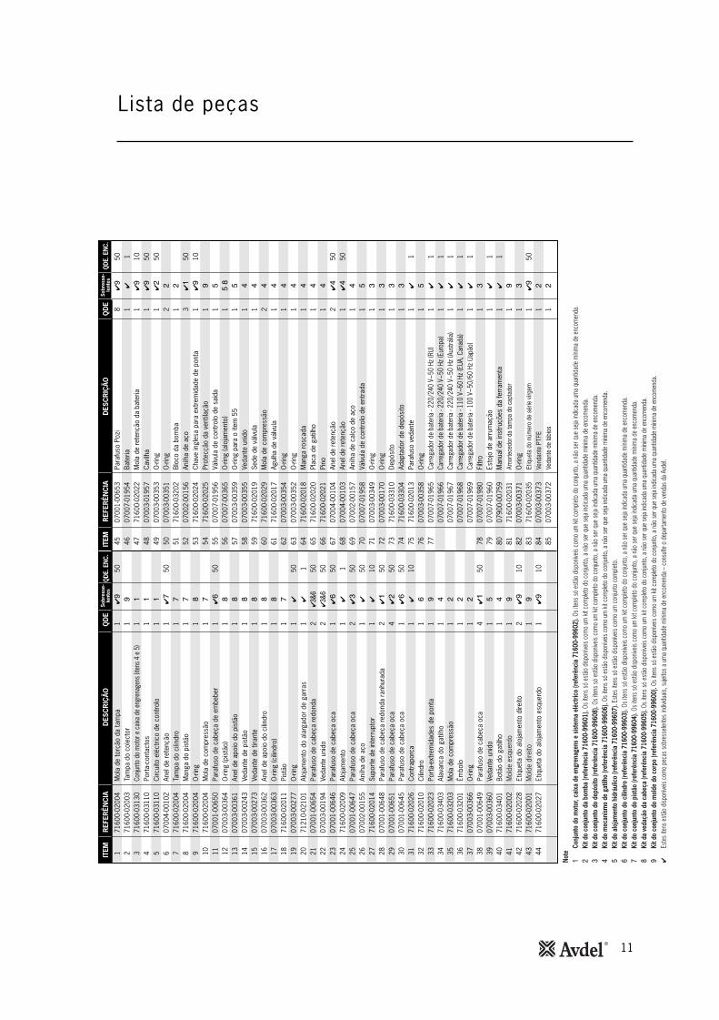
Lista de peças45
0700
1-00
653
8✔�
5046
0700
7-01
954
1✔
147
7160
0-02
022
1✔�
1048
0700
3-01
957
1✔�
5049
0700
3-00
353
1✔�
5050
0700
3-00
351
2�
5171
600-
0320
21
�
5207
002-
0015
63
✔�
5053
7160
0-02
024
1✔�
1054
7160
0-02
025
1�
5507
007-
0195
61
�
5607
007-
0036
51
��
5707
003-
0035
91
�
5807
003-
0035
51
�
5971
600-
0201
91
�
6071
600-
0202
92
�
6171
600-
0201
71
�
6207
003-
0035
41
�
6307
003-
0035
21
�
6471
600-
0201
81
�
6571
600-
0202
01
�
6671
600-
0202
11
�
6707
004-
0010
42
✔�
5068
0700
4-00
103
1✔�
5069
0700
2-00
157
1�
7007
007-
0195
81
�
7107
003-
0034
91
�
7207
003-
0017
01
�
7371
600-
0331
01
�
7471
600-
0330
41
�
7571
600-
0201
31
✔1
7607
003-
0035
81
�
7707
007-
0196
51
✔1
0700
7-01
966
1✔
107
007-
0196
71
✔1
0700
7-01
968
1✔
107
007-
0196
91
✔1
7807
007-
0198
01
�
7907
007-
0196
01
✔1
8007
900-
0075
91
✔1
8171
600-
0203
11
�
8207
003-
0037
11
�
8371
600-
0203
51
✔�
5084
0700
3-00
373
1�
8507
003-
0037
21
�
171
600-
0200
41
✔�
502
7160
0-02
003
1�
371
600-
0313
01
�
471
600-
0311
01
�
571
600-
0311
01
�
607
004-
0010
21
✔
507
7160
0-02
004
1
871
600-
0200
41
971
600-
0200
41
�
1071
600-
0200
41
1107
001-
0065
01
✔
5012
0700
3-00
364
1�
1307
003-
0036
11
�
1407
003-
0024
31
�
1507
003-
0027
31
�
1607
003-
0036
21
�
1707
003-
0036
31
�
1871
600-
0201
11
1907
003-
0027
71
✔50
2071
210-
0210
11
✔1
2107
001-
0065
42
✔��
5022
0700
3-00
194
2✔��
5023
0700
1-00
646
1✔
5024
7160
0-02
009
1✔
125
0700
1-00
647
2✔�
5026
0700
2-00
155
1✔
5027
7160
0-02
014
1✔
1028
0700
1-00
648
2✔�
5029
0700
1-00
651
4✔�
5030
0700
1-00
645
1✔
5031
7160
0-02
026
1✔
1032
7160
0-02
010
1
3371
600-
0202
31
�
3471
600-
0340
31
�
3571
600-
0320
31
�
3671
600-
0320
11
�
3707
003-
0036
61
�
3807
001-
0064
94
✔�
5039
0700
3-00
360
1�
4071
600-
0340
11
�
4171
600-
0200
21
�
4271
600-
0202
82
✔�
1043
7160
0-02
001
1�
4471
600-
0202
71
✔�
10
Note
�Co
njun
to d
o m
otor
, cai
xa d
e en
gren
agen
s e
siste
ma
eléc
trico
(ref
erên
cia
7160
0-99
602)
.Os i
tens
só e
stão
dispo
níveis
com
o um
kit c
omple
to d
o co
njunt
o, a
não
ser q
ue se
ja ind
icada
uma
quan
tidad
e m
ínim
a de
enc
omen
da.
�Ki
t do
conj
unto
da
bom
ba (r
efer
ênci
a 71
600-
9960
1). O
s ite
ns só
estã
o dis
ponív
eis c
omo
um ki
t com
pleto
do
conju
nto,
a nã
o se
r que
seja
indica
da um
a qu
antid
ade
míni
ma
de e
ncom
enda
.�
Kit d
o co
njun
to d
o de
pósit
o (re
ferê
ncia
716
00-9
9608
).Os
iten
s só
estã
o dis
ponív
eis c
omo
um ki
t com
pleto
do
conju
nto,
a nã
o se
r que
seja
indica
da um
a qu
antid
ade
míni
ma
de e
ncom
enda
.�
Kit d
o m
ecan
ismo
de g
atilh
o (re
ferê
ncia
716
00-9
9606
).Os
iten
s só
estã
o dis
ponív
eis c
omo
um ki
t com
pleto
do
conju
nto,
a nã
o se
r que
seja
indica
da um
a qu
antid
ade
míni
ma
de e
ncom
enda
.�
Kit d
o al
ojam
ento
hid
rául
ico
(refe
rênc
ia 7
1600
-996
07).
Este
s ite
ns só
estã
o dis
ponív
eis c
omo
um c
onjun
to c
omple
to.
Ki
t do
conj
unto
do
cilin
dro
(refe
rênc
ia 7
1600
-996
03).
Os it
ens s
ó es
tão
dispo
níveis
com
o um
kit c
omple
to d
o co
njunt
o, a
não
ser q
ue se
ja ind
icada
uma
quan
tidad
e m
ínim
a de
enc
omen
da.
Ki
t do
conj
unto
do
pist
ão (r
efer
ênci
a 71
600-
9960
4).O
s ite
ns só
estã
o dis
ponív
eis c
omo
um ki
t com
pleto
do
conju
nto,
a nã
o se
r que
seja
indica
da um
a qu
antid
ade
míni
ma
de e
ncom
enda
.�
Kit d
a ve
daçã
o da
cab
eça
(refe
rênc
ia 7
1600
-996
05).
Os it
ens s
ó es
tão
dispo
níveis
com
o um
kit c
omple
to d
o co
njunt
o, a
não
ser q
ue se
ja ind
icada
uma
quan
tidad
e m
ínim
a de
enc
omen
da.
�Ki
t do
conj
unto
do
mol
de d
o co
rpo
(refe
rênc
ia 7
1600
-996
00).
Os it
ens s
ó es
tão
dispo
níveis
com
o um
kit c
omple
to d
o co
njunt
o, a
não
ser q
ue se
ja ind
icada
uma
quan
tidad
e m
ínim
a de
enc
omen
da.
✔Es
tes i
tens
estã
o dis
ponív
eis c
omo
peça
s sob
ress
elent
es in
dividu
ais, s
ujeito
s a um
a qu
antid
ade
míni
ma
de e
ncom
enda
– c
onsu
lte o
dep
arta
men
to d
e ve
ndas
da
Avde
l.
Mol
a de
torç
ão d
a ta
mpa
Tam
pa d
o co
lect
orCo
njunt
o do
mot
or e
caix
a de
eng
rena
gens
(ite
ns 4
e 5
)Po
rta-
cont
acto
sCi
rcui
to e
léct
rico
de c
ontro
loAn
el d
e re
tenç
ãoTa
mpa
do
cilin
dro
Man
ga d
o pi
stão
O-ri
ngM
ola
de c
ompr
essã
oPa
rafu
so d
e ca
beça
de
embe
ber
O-ri
ng (p
istã
o)An
el d
e ap
oio
do p
istã
oVe
dant
e de
pis
tão
Veda
nte
de ti
rant
eAn
el d
e ap
oio
do c
ilindr
oO
-ring
(cilin
dro)
Pist
ãoO
-ring
Aloj
amen
to d
o al
arga
dor
de g
arra
sPa
rafu
so d
e ca
beça
redo
nda
Veda
nte
unid
oPa
rafu
so d
e ca
beça
oca
Aloj
amen
toPa
rafu
so d
e ca
beça
oca
Anilh
a de
aço
Supo
rte
de in
terr
upto
rPa
rafu
so d
e ca
beça
redo
nda
ranh
urad
a Pa
rafu
so d
e ca
beça
oca
Para
fuso
de
cabe
ça o
caCo
ntra
porc
aCi
lindr
oPo
rta-
extre
mid
ades
de
pont
aAl
avan
ca d
o ga
tilho
Mol
a de
com
pres
são
Êmbo
loO
-ring
Para
fuso
de
cabe
ça o
caVe
dant
e un
ido
Botã
o do
gat
ilho
Mol
de e
sque
rdo
Etiq
ueta
do
aloj
amen
to d
ireito
Mol
de d
ireito
Etiq
ueta
do
aloj
amen
to e
sque
rdo
Para
fuso
Poz
iBa
teria
Mol
a de
rete
nção
da
bate
riaCa
vilh
aO
-ring
O-ri
ngBl
oco
da b
omba
Anilh
a de
aço
Chav
e in
gles
a pa
ra e
xtre
mid
ade
de p
onta
Prot
ecçã
o da
ven
tilaç
ãoVá
lvul
a de
con
trolo
de
saíd
aO
-ring
(alo
jam
ento
)O
-ring
par
a o
item
55
Veda
nte
unid
oSe
de d
e vá
lvul
aM
ola
de c
ompr
essã
oAg
ulha
de
válv
ula
O-ri
ngO
-ring
Man
ga ro
scad
aPl
aca
de g
atilh
oPi
noAn
el d
e re
tenç
ãoAn
el d
e re
tenç
ãoAn
ilha
de c
alço
de
aço
Válv
ula
de c
ontro
lo d
e en
trad
aO
-ring
O-ri
ngDe
pósi
toAd
apta
dor
de d
epós
itoPa
rafu
so v
edan
teO
-ring
Carre
gado
r de
bate
ria -
220/
240
V~50
Hz
(RU)
Carre
gado
r de
bate
ria -
220/
240
V~50
Hz
(Eur
opa)
Carre
gado
r de
bate
ria -
220/
240
V~50
Hz
(Aus
trália
)Ca
rrega
dor d
e ba
teria
- 11
0 V~
60 H
z (E
UA, C
anad
á)Ca
rrega
dor d
e ba
teria
- 10
0 V~
50/6
0 Hz
(Jap
ão)
Filtr
oEs
tojo
de
arru
maç
ãoM
anua
l de
inst
ruçõ
es d
a fe
rram
enta
� �����������
�� ��
����������
O-ri
ng����������
�� �����
�����
�����
�������!"#�
��������
$%&���
ITEM
REF
ERÊN
CIA
DES
CR
IÇÃO
QD
ESo
bres
se-
lent
esIT
EMR
EFER
ÊNC
IAD
ESC
RIÇ
ÃOQ
DE
Sobr
esse
-le
ntes
QDE.
ENC
.QD
E. E
NC.

12
Dec laração de Conformidade
Nós, a Avdel UK Limited; Watchmead Industrial Estate, Welwyn Garden City, Hertfordshire, AL7 1LY
declaramos sob a nossa única e inteira responsabilidade que o produto:
Modelo TX2000
Nº de Série................................................
A que se refere a presente declaração está em conformidade com as seguintes normas:
TX2000 Carregador de bateria
EN ISO 12100 - partes 1 e 2 VDE0700
EN 50260 - partes 1 EN 60335-1
BS EN 982 EN 60335-2-29
BS EN ISO 8662 - parte 6 EN 60742/0695
BS EN ISO 3744 EN 50081-1
ISO EN 792 - parte 13 - 2000 EN 55014
BS EN ISO 11202 EN 60555-2/3
BS EN 55014 - partes 1 e 2 EN 50082-1
BS EN 50081 - parte 1 EN 55104
Seguindo as disposições da Directiva Máquinas 2006/42/EC.
Este estojo contém uma ferramenta eléctrica que estáem conformidade com a Directiva Máquinas2006/42/EC. A "Declaração de Conformidade" estáincluída.
Data de Emissão
A. Seewraj - Gestor de Engenharia de Produtos - Ferramentas Automatizadas

13
Notas

14
Notas

15
Notas

Since 1 936 2010 Since 1922
www.avdel-global.comwww.infastech.com
02.2
011
• ©
201
0 In
fast
ech
Autosert® (equipment), Avbolt ®, Avdel®, Avdelmate®, Avdel TX2000®, Avdelok®, Avex®, Avibulb®, Avinox®, Avinut™, Avlug®, Avmatic®, Avplas®,Avseal®, Avsert®, Avtainer®, Avtronic®, Briv®, Bulbex®, Chobert®, Eurosert®, Fastriv®, Finsert®, Genesis®, Grovit®, Hemlok®, Hexsert®, Holding your world together®, Hydra®, Interlock®, Klamp-Tite®, Klamptite KTR®, Kvex®, Maxlok®, Monobolt®, Monobulb ®, Neobolt®, Nutsert®, Nutsert SQ®, Portariv®, Rivmatic®, Rivscrew®, Speed Fastening®, Squaresert®, Stavex®, Supersert®, Thin Sheet Nutsert®, Titan®, T-Lok®, TLR®, TSN®, TX2000®, Versa-Nut®, Viking® e Viking 360 ® são marcas comerciais da Avdel UK Limited. Infastech™ e Our Technology, Your Success™ são marcas comerciais da Infastech Intellectual Properties Pte Ltd. Os nomes e logótipos de outras empresas mencionadas neste documento podem ser marcas comerciais dos seus respectivos proprietários. Este documento tem objectivos meramente informativos. A Infastech não oferece quaisquer garantias, explícitas ou implícitas, neste documento. Os dados apresentados estão sujeitos a alterações sem aviso prévio em virtude do desenvolvimento contínuo do produto e do melhoramento da política. O seu representante local Avdel está à sua disposição caso precise de confirmar esta última informação.
AUSTRÁLIAInfastech (Australia) Pty Ltd.891 Wellington RoadRowvilleVictoria 3178Tel: +61 3 9765 6400Fax: +61 3 9765 [email protected]
CANADÁAvdel Canada Limited1030 Lorimar DriveMississaugaOntario L5S 1R8Tel: +1 905 364 0664Fax: +1 905 364 [email protected]
CHINAInfastech (China) Ltd.RM 1708, 17/F., Nanyang Plaza,57 Hung To Rd., Kwun TongHong KongTel: +852 2950 0631Fax: +852 2950 [email protected]
FRANÇAAvdel France S.A.S.33 bis, rue des ArdennesBP4 75921 Paris Cedex 19Tel: +33 (0) 1 4040 8000Fax: +33 (0) 1 4208 [email protected]
ALEMANHAAvdel Deutschland GmbHKlusriede 2430851 LangenhagenTel: +49 (0) 511 7288 0Fax: +49 (0) 511 7288 [email protected]
ÍNDIAInfastech Fastening Technologies India Private LimitedPlot No OZ-14, Hi Tech SEZ,SIPCOT Industrial Growth Center,Oragadam, Sriperumbudur Taluk, Kanchipuram District,602105 TamilnaduTel: +91 44 4711 8001Fax: +91 44 4711 [email protected]
ITÁLIAAvdel Italia S.r.l.Viale Lombardia 51/5320047 Brugherio (MI)Tel: +39 039 289911Fax: +39 039 [email protected]
JAPÃOInfastech Kabushiki KaishaCenter Minami SKY, 3-1 Chigasaki-Chuo, Tsuzuki-ku,Yokohama-city, Kanagawa PrefectureJapan 224-0032Tel: +81 45 947 1200Fax: +81 45 947 [email protected]
MALÁSIAInfastech (Malaysia) Sdn BhdLot 63, Persiaran Bunga Tanjung 1,Senawang Industrial Park70400 SerembanNegeri SembilanTel: +606 676 7168Fax: +606 676 [email protected]
SINGAPURAInfastech (Singapore) Pte Ltd. 31 Kaki Bukit Road 3#05-03/06 TechlinkSingapore, 417818Tel: +65 6372 5653Fax: +65 6744 [email protected]
REPÚBLICA DA COREIAInfastech (Korea) Ltd.212-4, Suyang-Ri,Silchon-Eup, Kwangju-City,Kyunggi-Do, Korea, 464-874Tel: +82 31 798 6340Fax: +82 31 798 [email protected]
ESPANHAAvdel Spain S.A.C/ Puerto de la Morcuera, 14Poligono Industrial Prado OveraCtra. de Toledo, km 7,828919 Leganés (Madrid)Tel: +34 91 3416767Fax: +34 91 [email protected]
TAIWANInfastech/Tri-Star LimitedNo 269-7, Baodong Rd, Guanmiao Township,71841 Tainan County,Taiwan, R.O.CTel: +886 6 596 5798 (ext 201)Fax: +886 6 596 [email protected]
REINO UNIDOAvdel UK LimitedPacific House2 SwiftfieldsWatchmead Industrial EstateWelwyn Garden CityHertfordshire AL7 1LYTel: +44 (0) 1707 292000Fax: +44 (0) 1707 [email protected]
EUAAvdel USA LLC614 NC Highway 200 SouthStanfield, North Carolina 28163Tel: +1 704 888 7100Fax: +1 704 888 [email protected]
Manual No. Issue Change Note No.
AB 03/022
B 07/044
B2 07/142
B3 11/081
07900-00790

Serv i ce Manua lOr ig i na l I ns t ruc t i on
TX2000
Bat tery Powered Too l


3
Contents
Annual ServiceService Kit 4Before Dismantling 4
Repairs & Major ServiceMoulded Body Assembly 5Pump Assembly 6Motor, Gearbox, Electrical Assembly 6Head Assembly 7Trigger Mechanism 8Housing Assembly 8Reservoir Assembly 9Troubleshooting 9
Assembly Diagram & Base Tool 10
Parts List 11
This manual is only for use by Avdel® authorised distributors and repair centres.
IMPORTANT: The warranty is invalidated if the installation tool is not identifiedwith a relevant serial number label. The label is positioned internally, at the baseof the handle, on the left moulding, 41. When replacing the moulded body a newlabel, 83, must be inserted and marked by hand with the tool's original serialnumber.

4
Annual/500,000 Cyc le Serv ice
Annua l Serv ice
Spanners are specified in inches and across flats unless otherwise stated
• Every 500,000 cycles the tool should be completely dismantled and new components should be used where worn, damaged or
recommended. All ‘O’ rings and seals should be renewed and lubricated with MolyKote 111 grease before assembling.
• For an easy complete service, Avdel offer a complete service kit as detailed below.
Service Kit: 71600-99990
Part No. Description
07900-00006 Spatular
07900-00008 7/16 x 1/2 Spanner
07900-00012 9/16 x 5/8 Spanner
07900-00015 5/8 x 11/16 Spanner
07900-00243 Screwdriver - Small
07900-00333 Screwdriver - Medium
07900-00469 2.5mm Allen Key
07900-00737 Piston Seal Sleeve
07900-00738 Piston Seal Tool
07900-00739 Piston Bullet
07900-00740 Cylinder Collar
07900-00741 Guide Tube
07900-00742 Insertion Rod
07900-00743 End Cap Assembly Tool
Part No. Description
07900-00748 Threaded Sleeve Bullet
07900-00747 Valve Seat Tool
07900-00749 Threaded Sleeve Tool
07900-00750 Valve Needle Sleeve
07900-00751 3mm Allen Key - Short Reach
07900-00753 Circlip Pliers - Small
07900-00754 Priming Pump
07900-00755 Grease - MolyKote 111 - 100g tube
07900-00756 Loctite® 243 Threadlocker
07900-00757 Scalpel
07900-00760 Pozi Screwdriver
07900-00788 Service Kit Storage Case
07900-00768 Reservoir Bullet
07900-00769 Trigger Tool
07992-00020 Grease - Moly-Lithium
Before dismantling:
• Disconnect the battery before any servicing or dismantling is attempted, unless specifically instructed otherwise.
• Care must be taken at all times to ensure that conditions are clean so that no foreign matter enters the tool or serious damage
may result.
• Empty the oil from the tool following the first three steps of the priming procedure. Refer to the priming procedure on pages 14
and 15 of the Instruction Manual.
• Remove the nose equipment.
For a complete service of the tool, we advise that you proceed with dismantling of sub-assemblies in the order shown on page 5.
After dismantling the tool we recommend that you replace all seals.
On reassembly it is essential to prime the tool and fit an appropriate nose assembly prior to operating.

5
Moulded Body Assembly
Repa i rs and Ma jor Serv ice
IMPORTANT: The warranty is invalidated if the installation tool is not identified with a relevant serial number label. The
label is positioned internally, at the base of the handle, on the left moulding, 41. When replacing the moulded body a
new label, 83, must be inserted and marked by hand with the tool's original serial number.
The moulded body assembly includes items 1, 2, 33, 41 to 45, 47, 48, 53, 54, 81 and 83. These parts are only available as a
complete Body Moulding Assembly Kit (part number 71600-99600), unless a minimum order quantity is provided in the parts list.
• Remove and discard label 42 from the right moulding 43 to reveal the hidden screw.
• Remove the nose tip spanner 53 and two nose tips from the moulded body.
• Place the tool on its side and using the pozi screwdriver unscrew all eight pozi screws 45 in the moulded body.
• Remove the right moulding 43 leaving the main internal mechanism within the left moulding 41 as shown on page 10.
• Remove the vent screen 54, battery retainer spring 47 and dowel pin 48 from the left moulding 41.
• Before removing the main internal mechanism ensure that the electrical control circuit 5 and the reservoir 73 are released from the
mounting points within the moulding.
• Holding the tool by the motor and gearbox assembly 3 remove the main internal mechanism from the moulding.
Assemble in reverse order to dismantling noting the following points:
• Place the main internal mechanism into the left moulding 41, first ensuring that the electrical control circuit 5 and the reservoir 73
are correctly placed within the mounting positions provided. The circuit board must be positioned so that the heat sink is facing
forward and the black and blue wires are at the top. The contact holder 4 must be positioned with the positive symbol in the left
moulding 41 as shown in the diagram below.
• The contact holder is designed to enable correct orientation in the mouldings. Care must be taken to ensure that the raised portion
on the right moulding 43 fits within the indent on the negative side of the contact holder 4.
• When replacing the right moulding 43 take care to ensure that no wires are trapped and correct alignment with the electrical
control circuit 5 and the vent screen 54 are achieved.
• When the moulded body is fully assembled with all eight pozi screws 45, insert new case label 42 on the right moulding 43.
IMPORTANT: Correct orientation of the contact holder 4 must be achieved when assembling into mouldings 41 and 43.
Incorrect assembly will cause short circuit and failure of electrical control circuit.
Left HandMoulding
Contact Holder
RecessedEdge

6
Motor, Gearbox and E lectr ica l Assembly
Pump Assembly
Repa i rs and Ma jor Serv ice
The pump assembly includes items 29, 35, 36, 37, 49, 51 and one of the following plunger seal combinations, either seals (37 and
50 2 off) or (37, 84 and 85). These parts are only available fully assembled as a complete Pump Assembly Kit (part number 71600-
99601), unless a minimum order quantity is provided in the parts list.
• Completely remove the main internal mechanism from the left and right mouldings 41, 43, as described on page 5.
• To gain access to the pump attachment screws 29 the trigger assembly, items 34, 40, must be removed. Using the circlip pliers
remove one circlip 67 from pin 66. Push the pin out allowing the trigger lever 34 and trigger button 40 to be removed.
• Hold the main internal mechanism and pump block 51 securely in position and using the 3 mm allen key remove the four
attachment screws 29. Remove the complete pump assembly from the housing 24. Care must be taken when removing the pump
assembly as the plunger 36 will be spring loaded.
• Remove the plunger 36 and spring 35 from the pump block 51 taking care not to damage the seals, plunger surface and the
pump block bore.
• Remove ‘O’ ring 49 from housing 24 and discard.
Assemble in reverse order to dismantling noting the following points:
• Clean the plunger 36 and apply a small amount of Molykote 111 grease to the seals using the spatula.
• Clean the pump block 51 bore and then lubricate with Molykote 111 grease using the spatula.
• Place spring 35 over the sealed plunger, align the end of the plunger with the pump block 51 bore and push into place until the
seals are no longer visible. When inserting the plunger take care not to damage the seals on the rim of the pump block bore.
• Apply a light film of Loctite® 243 threadlocker to all four screws 29.
• Attach the pump assembly onto the housing 24 as before using four screws 29 and the 3 mm allen key.
• Finally assemble the trigger assembly, items 34, 40, and pin 66 in reverse order to dismantling.
The motor, gearbox and electrical assembly includes items 3, 4, 5, 28, 38 and 52. These parts are only available as a complete
assembly (part number 71600-99602), unless a minimum order quantity is provided in the parts list.
• Completely remove the main internal mechanism from the left and right mouldings 41, 43, as described on page 5.
• Remove the ‘pump assembly’ as described above.
• Using the small screwdriver remove the two screws 28 that retain the micro-switch to the switch bracket 27.
• Using the 3 mm allen key remove all three screws 38 and washers 52 attaching the gearbox to the housing 24.
• Remove the complete motor, gearbox and electrical assembly 3, 4 and 5 from the housing 24.
Assemble in reverse order of dismantling noting the following points:
• Ensure that the motor and gearbox assembly, when connected to the housing 24, is orientated so that the groove in the gearbox
mounting plate is at the top.
• Apply Loctite® 243 threadlocker to all three screws 38.
• DO NOT USE UNDUE FORCE when inserting the three screws 38 into the housing 24.

7
Head Assembly
Repa i rs and Ma jor Serv ice
The head assembly consists of three assembly kits, Cylinder Assembly Kit (part number 71600-99603), Piston Assembly Kit (part
number 71600-99604) and Head Seal Kit (part number 71600-99605) containing items 6 to 18, 21, 22, 23, 30 and 32. These
parts are only available as complete kits unless a minimum order quantity is provided in the parts list.
• Completely remove the main internal mechanism from the left and right mouldings 41, 43, as described on page 5.
• Remove the complete motor, gearbox and electrical assembly 3, 4 and 5 as described on page 6.
• Unscrew locknut 31 and jaw spreader housing 20 from the piston 18.
• Using the 3 mm and 2.5 mm allen keys remove screws 11, 23, 30, clamping the cylinder 32 to the housing 24.
• Remove the head assembly from the housing. Remove ‘O’ ring 56 from the housing and discard.
• Grip the head assembly in a vice using soft jaws to avoid damage.
• Using the end cap assembly tool unscrew and remove the cylinder cap assembly, items 6, 7, 8, 9 from the rear of the cylinder 32.
Care must be taken as the cylinder cap 7 will be spring loaded.
• Remove and discard the spring 10 from inside the cylinder 32.
• Push the piston 18 to the rear and out of the cylinder 32 taking care not to damage the cylinder bore.
• Using the medium screwdriver enter the rear of the cylinder 32, lever the rod seal 15 from the groove and cut through with a
scalpel taking care not to damage the cylinder bore or the seal groove. Using the spatula push the rod seal, followed by bearing
ring 16 and ‘O’ ring 17 to the rear and out of the cylinder. If at any time the cylinder bore or seal groove become damaged the
cylinder must be replaced.
• Using a scalpel cut through and remove the piston seal 14 from the piston 18. Then remove bearing ring 13 and ‘O’ ring 12. Take
care not to damage the piston when cutting the seal.
Assemble in reverse order to dismantling noting the following points:
• Clean all components before assembling.
• To aid assembly of seals apply a light coating of Molykote 111 grease to both the seals and the assembly tools.
• Lubricate the cylinder 32 bore and seal grooves with Molykote 111 grease. Insert the bearing ring 16 into place within cylinder.
With the aid of the spatula insert the ‘O’ ring 17. Place the rod seal 15 onto the insertion rod ensuring correct orientation. Push the
guide tube into the cylinder bore and push the insertion rod with the seal into place through the guide tube ensuring seal is
correctly seated. Pull the insertion rod out then the guide tube.
• Lubricate the piston 18 shaft and seal grooves with Molykote 111 grease and fit ‘O’ ring 12 and bearing ring 13. Place the piston
seal sleeve over the piston shaft, then slide the piston seal 14 over the sleeve and into position using the piston seal tool ensuring
correct orientation.
• Insert the cylinder collar into the back of the cylinder 32. Screw the piston bullet onto the piston 18 and push the piston with the seals
through the cylinder collar as far as it will go. Unscrew the bullet off the piston and remove the cylinder collar.
• Apply a light coating of Moly-lithium grease to the surface and ends of the spring 10 before inserting onto the piston 18 within the
cylinder.
• Screw the cylinder cap assembly, items 6, 7, 8, 9, into the cylinder 32 using the ‘T’-bar and end cap assembly tool.
• Insert ‘O’ ring 56 into the housing and lubricate with Molykote 111 grease.
• Fit the head assembly to the housing 24 using the three screws 11, 23, 30, coated with Loctite® 243 threadlocker.
• When inserting jaw spreader housing 20 onto piston 18, screw down fully until it bottoms out on the end of the piston shaft.
Secure jaw spreader housing 20 using locknut 31.

8
Tr igger Mechan ism
Hous ing Assembly
Repa i rs and Ma jor Serv ice
The trigger mechanism includes items 34, 40, 58 to 69. These parts are only available as a complete Trigger Mechanism Kit (part
number 71600-99606), unless a minimum order quantity is provided in the parts list.
• Completely remove the main internal mechanism from the left and right mouldings 41, 43, as described on page 5.
• Using the circlip pliers remove one circlip 67 from pin 66. Push the pin out allowing the trigger lever 34 and trigger button 40 to
be removed.
• Using the circlip pliers carefully remove circlip 68 from the valve needle 61, followed by shim 69, trigger plate 65 and spring 60.
Discard the spring 60.
• Using the threaded sleeve tool unscrew and remove the threaded sleeve 64 from the housing 24. Remove ‘O’ ring 62 from the
threaded sleeve and discard.
• Remove the valve needle 61 from the housing 24, then remove and discard the spring 60 from the valve needle 61. Using a
scalpel cut ‘O’ ring 63 from the valve needle taking care not to damage the seal groove.
• Using the valve seat tool unscrew the valve seat 59 and remove from the housing 24. Remove bonded seal 58 from valve seat
and discard.
Assemble in reverse order to dismantling noting the following points:
• Clean all components before assembling.
• Lubricate valve needle 61 shaft and seal groove with Molykote 111 grease and place the valve needle tool over the end of the
valve needle 61. Slide ‘O’ ring 63 over the valve needle sleeve and into the seal groove on valve needle. Remove the valve needle
sleeve from the valve needle.
• Lubricate threaded sleeve 64 with Molykote 111 grease and place the threaded sleeve bullet over the end of the threaded sleeve.
Slide ‘O’ ring 62 over the threaded sleeve bullet and into the seal groove on threaded sleeve. Remove bullet from threaded sleeve.
• DO NOT USE UNDUE FORCE when inserting the valve seat 59 into the housing 24.
• When fitting threaded sleeve 64 into housing 24, ensure the component is screwed fully down until stopping against the valve seat
59.
• When fitting trigger plate 65, ensure correct orientation is achieved.
• Using the trigger tool and pin 66 in place of the trigger lever 34, fully compress the trigger plate 65 into the threaded sleeve 64
against the spring 60. The end of the valve needle 61 will become exposed. Place the shim 69 over the valve needle and then
insert the circlip 68 into the groove using the circlip pliers. Release and remove the trigger tool.
The housing assembly consists of items 24 to 27, and 38, all of which are available as individual parts, subject to a minimum order
quantity. The assembly also contains items 39, 55, 56, 57, 70, 75 and 76. These parts are only available as a complete Housing
Hydraulic Kit (part number 71600-99607).
• Completely remove the main internal mechanism from the left and right mouldings 41, 43, as described on page 5.
• Do not remove screws 25, 38, from the housing 24.
• Using medium screwdriver unscrew seal screw 75 from housing 24. Remove ‘O’ ring 76 from seal screw.
• Using medium screwdriver unscrew inlet check valve 70 from housing 24.
• In order to remove outlet check valve 55 the head assembly must be removed as described on page 7.
• Using medium screwdriver unscrew outlet check valve 55 from housing 24. Remove ‘O’ ring 57 from outlet check valve and
discard.
• Assemble in reverse order to dismantling.

9
Reservo i r Assembly
Troub leshoot ing
Repa i rs and Ma jor Serv ice
The reservoir assembly includes items 21, 22, 25, 78, 82 and 71 to 74. These parts are only available as a complete Reservoir
Assembly Kit (part number 71600-99608), unless a minimum order quantity is provided in the parts list.
• Completely remove the main internal mechanism from the left and right mouldings 41, 43, as described on page 5.
• Using the 3 mm allen key remove screw 21 and bonded seal 22 from reservoir 73.
• Using the spatular remove 'O' ring 72 from reservoir 73 and discard.
• Remove reservoir 73 from reservoir adapter 74.
• Using the 2.5 mm allen key, remove screw 25 attaching reservoir adapter 74 to housing 24.
• Remove reservoir adapter 74 from housing 24.
• Remove 'O' ring 71 from reservoir adapter 74 and discard.
• Do not remove the filter 78, or the 'O' ring 82, from the reservoir adapter 74 unless damaged. If removed discard both items.
Assemble in reverse order to dismantling noting the following points:
• Lubricate both ‘O’ ring 71 and seal groove on reservoir adapter. Place ‘O’ ring 71 in reservoir adapter 74.
• Using 2.5 mm allen key and screw 25 fit reservoir adapter 74 to housing noting correct orientation with the holes.
• Slide open end of reservoir 73 over reservoir adapter 74 and into position within the groove.
• Place the reservoir bullet over the closed end of reservoir 73. Slide ‘O’ ring 72 completely over the bullet until it falls into place
around the end of the reservoir 73, holding it in securely around the reservoir adapter 74.
• Ensure that the reservoir 73 is correctly positioned on the reservoir adapter 74, so that the flat face on the metal part of the
reservoir is at the top.
IMPORTANT: Check the tool against daily and weekly servicing.
Priming is ALWAYS necessary after the tool has been dismantled and prior to operating.
Fastener fails to break Trigger mechanism springs worn Replace trigger mechanism 8
Jaws will not release Damaged spring in head assembly Fit new spring 7
broken stem of fastener
Tool fails to operate - Pump plunger jammed Replace pump spring 6
motor operational:
if head piston static Inlet check valve faulty Replace inlet check valve 8
if head piston pulsing Outlet check valve faulty Replace outlet check valve 8
Tool fails to operate - Motor or gearbox failure Test and replace any defective equipment 6
motor not operational Electrical control circuit failure Test and replace any defective equipment 6
Symptom Poss ib le Cause Remedy Page Ref

10
Genera l Assembly o f Base Too l 71600-02000
A
41
235
67
89
1011
1213
1415
1617
1819
2021
22
23 24 25 5Re
f
26 27
31 32
33
34
35
36
37
38 39
4
42, 4
3Ri
ght H
and
41, 4
4Le
ft H
and
45
46
50
49
48
47
5
38
51
52
VIE
W O
NA
ENLA
RGED
VIE
W O
FTR
IGG
ER M
ECH
AN
ISM
INTE
RNA
LM
ECH
AN
ISM
(EXC
LUD
ING
MO
ULD
ING
S)
ALT
ERN
ATIV
E PU
MP
A
RRA
NG
EMEN
T
53
5455
5657
58
59 60
60
61 62 63 64 65 66 6768
69
7025
7172
73
7675
7482
29
84
30
28
81
40
21 22
78
8537

11
Par ts L is t
4507
001-
0065
2Po
zi s
crew
8 9
5046
0700
7-01
954
Batte
ry1
147
7160
0-02
022
Batte
ry re
tain
er s
prin
g1
910
4807
007-
0195
7Do
wel
pin
1 9
5049
0700
3-00
353
O-ri
ng1
250
5007
003-
0035
1O
-ring
22
5171
600-
0320
2Pu
mp
bloc
k1
252
0700
2-00
156
Stee
l was
her
3 1
5053
7160
0-02
024
Nos
e tip
spa
nner
1 9
1054
7160
0-02
025
Vent
scr
een
19
5507
007-
0195
6O
utle
t che
ck v
alve
15
5607
007-
0036
5O
-ring
(hou
sing
)1
5 8
5707
003-
0035
9O
-ring
for
item
55
15
5807
003-
0035
5Bo
nded
sea
l1
459
7160
0-02
019
Valv
e se
at1
460
7160
0-02
029
Com
pres
sion
spr
ing
24
6171
600-
0201
7Va
lve
need
le1
462
0700
3-00
354
O-ri
ng1
463
0700
3-00
352
O-ri
ng1
464
7160
0-02
018
Thre
aded
sle
eve
14
6571
600-
0202
0Tr
igge
r pl
ate
14
6671
600-
0202
1Pi
n1
467
0700
4-00
104
Circ
lip2
450
6807
004-
0010
3Ci
rclip
1 4
5069
0700
2-00
157
Stee
l shi
m w
ashe
r1
470
0700
7-01
958
Inle
t che
ck v
alve
15
7107
003-
0034
9O
-ring
13
7207
003-
0017
0O
-ring
13
7371
600-
0331
0Re
serv
oir
13
7471
600-
0330
4Re
serv
oir
adap
ter
13
7571
600-
0201
3Se
al s
crew
11
7607
003-
0035
8O
-ring
15
7707
007-
0196
5Ba
ttery
cha
rger
- 22
0/24
0V~
50Hz
(UK)
11
0700
7-01
966
Batte
ry c
harg
er -
220/
240V
~50
Hz (E
urop
e)1
107
007-
0196
7Ba
ttery
cha
rger
- 22
0/24
0V~
50Hz
(Aus
tral
ia)
11
0700
7-01
968
Batte
ry c
harg
er -
110V
~60
Hz (U
SA, C
anad
a)1
107
007-
0196
9Ba
ttery
cha
rger
- 10
0V~
50/6
0Hz
(Jap
an)
11
7807
007-
0198
0Fi
lter
13
7907
007-
0196
0St
orag
e ca
se1
180
0790
0-00
759
Tool
Inst
ruct
ion
Man
ual -
UK
vers
ion
11
8171
600-
0203
1Co
llect
or li
d bu
ffer
19
8207
003-
0037
1'O
' Rin
g1
383
7160
0-02
035
Blan
k se
rial n
umbe
r la
bel
1 9
5084
0700
3-00
373
Ener
gise
d PT
FE s
eal
12
8507
003-
0037
2En
ergi
sed
lip le
al1
2
171
600-
0200
4Li
d to
rsio
n sp
ring
1 9
502
7160
0-02
003
Colle
ctor
lid
19
371
600-
0313
0M
otor
& g
earb
ox a
ssem
bly
11
471
600-
0311
0Co
ntac
t hol
der
11
571
600-
0311
0El
ectr
ical
con
trol c
ircui
t1
16
0700
4-00
102
Circ
lip1
750
771
600-
0201
6Cy
linde
r ca
p1
78
7160
0-02
015
Pist
on s
leev
e1
79
0700
3-00
350
O-ri
ng1
810
7160
0-02
012
Com
pres
sion
spr
ing
17
1107
001-
0065
0So
cket
csk
hea
d sc
rew
1 6
5012
0700
3-00
364
O-ri
ng (p
isto
n)1
813
0700
3-00
361
Pist
on b
earin
g rin
g1
814
0700
3-00
243
Pist
on s
eal
18
1507
003-
0027
3Ro
d se
al1
816
0700
3-00
362
Cylin
der
bear
ing
ring
18
1707
003-
0036
3O
-ring
(cyl
inde
r)1
818
7160
0-02
011
Pist
on1
719
0700
3-00
277
O-ri
ng1
5020
7121
0-02
101
Jaw
spr
eade
r ho
usin
g 1
121
0700
1-00
654
Butto
n he
ad s
crew
23
&6
5022
0700
3-00
194
Bond
ed s
eal
23
&6
5023
0700
1-00
646
Sock
et c
ap h
ead
scre
w1
650
2471
600-
0200
9Ho
usin
g1
125
0700
1-00
647
Sock
et c
ap h
ead
scre
w2
350
2607
002-
0015
5St
eel w
ashe
r1
5027
7160
0-02
014
Switc
h br
acke
t1
1028
0700
1-00
648
Slot
ted
chee
se h
ead
scre
w2
150
2907
001-
0065
1So
cket
cap
hea
d sc
rew
4 2
5030
0700
1-00
645
Sock
et c
ap h
ead
scre
w1
650
3171
600-
0202
6Lo
cknu
t1
1032
7160
0-02
010
Cylin
der
16
3371
600-
0202
3N
ose
tip h
olde
r1
934
7160
0-03
403
Trig
ger
leve
r1
435
7160
0-03
203
Com
pres
sion
spr
ing
12
3671
600-
0320
1Pl
unge
r1
237
0700
3-00
366
O-ri
ng1
238
0700
1-00
649
Sock
et c
ap h
ead
scre
w4
150
3907
003-
0036
0Bo
nded
sea
l1
540
7160
0-03
401
Trig
ger
butto
n1
441
7160
0-02
002
Left
mou
ldin
g1
942
7160
0-02
028
Case
labe
l RH
2 9
1043
7160
0-02
001
Righ
t mou
ldin
g1
944
7160
0-02
027
Case
labe
l LH
1 9
10
ITEM
PART
Nº
DES
CR
IPTI
ON
QTY
SPAR
ESIT
EMPA
RT N
ºD
ESC
RIP
TIO
NQ
TYSP
ARES
MIN
ORDE
R QT
YM
INOR
DER
QTY
Not
e1
Mot
or, G
earb
ox a
nd E
lect
rica
l Ass
embl
y (p
art n
umbe
r 71
600-
9960
2).
Thes
e ite
ms
are
only
ava
ilabl
e as
a c
ompl
ete
asse
mbl
y ki
t unl
ess
a m
inim
um o
rder
qua
ntity
is s
tate
d.2
Pum
p As
sem
bly
Kit
(par
t num
ber
7160
0-99
601)
. Th
ese
item
s ar
e on
ly a
vaila
ble
as a
com
plet
e as
sem
bly
unle
ss a
min
imum
ord
er q
uant
ity is
sta
ted.
3R
eser
voir
Ass
embl
y K
it (p
art n
umbe
r 71
600-
9960
8).
Thes
e ite
ms
are
only
ava
ilabl
e as
a c
ompl
ete
asse
mbl
y ki
t unl
ess
a m
inim
um o
rder
qua
ntity
is s
tate
d.4
Trig
ger
Mec
hani
sm K
it (p
art n
umbe
r 71
600-
9960
6).
Thes
e ite
ms
are
only
ava
ilabl
e as
a c
ompl
ete
asse
mbl
y ki
t unl
ess
a m
inim
um o
rder
qua
ntity
is s
tate
d.5
Hou
sing
Hyd
raul
ic K
it (p
art n
umbe
r 71
600-
9960
7).
Thes
e ite
ms
are
only
ava
ilabl
e as
a c
ompl
ete
kit.
6C
ylin
der
Asse
mbl
y K
it (p
art n
umbe
r 71
600-
9960
3).
Thes
e ite
ms
are
only
ava
ilabl
e as
a c
ompl
ete
asse
mbl
y ki
t unl
ess
a m
inim
um o
rder
qua
ntity
is s
tate
d.7
Pist
on A
ssem
bly
Kit
(par
t num
ber
7160
0-99
604)
. Th
ese
item
s ar
e on
ly a
vaila
ble
as a
com
plet
e as
sem
bly
kit u
nles
s a
min
imum
ord
er q
uant
ity is
sta
ted.
8H
ead
Seal
Kit
(par
t num
ber
7160
0-99
605)
. Th
ese
item
s ar
e on
ly a
vaila
ble
as a
com
plet
e as
sem
bly
kit u
nles
s un
less
a m
inim
um o
rder
qua
ntity
is s
tate
d.9
Bod
y M
ould
ing
Asse
mbl
y K
it (p
art n
umbe
r 71
600-
9960
0).
Thes
e ite
ms
are
only
ava
ilabl
e as
a c
ompl
ete
asse
mbl
y ki
t unl
ess
a m
inim
um o
rder
qua
ntity
is s
tate
d.Th
ese
item
s ar
e av
aila
ble
as in
divi
dual
spa
res
subj
ect t
o th
e m
inim
um o
rder
qua
ntity
- re
fer
to A
vdel
sal
es.

12
Notes

13
Notes

Notes
14

15
Dec lara t ion o f Conformi ty
We, Avdel UK Limited, Watchmead Industrial Estate, Welwyn Garden City, Herts, AL7 1LY
declare under our sole responsibility that the product:
Model TX2000
Serial No. ................................................
to which this declaration relates is in conformity with the following standards:
TX2000 Tool Battery Charger
EN ISO 12100 - parts 1 & 2 VDE0700
EN 50260 - part 1 EN 60335-1
BS EN 982 EN 60335-2-29
BS EN ISO 8662 - part 6 EN 60742/0695
BS EN ISO 3744 EN 50081-1
ISO EN 792 part 13 - 2000 EN 55014
BS EN ISO 11202 EN 60555-2/3
BS EN 55014 part 1 & 2 EN 50082-1
BS EN 50081 part 1 EN 55104
following the provisions of the Machine Directive 2006/42/EC.
This box contains a power tool which is in conformity with
Machines Directive 2006/42/EC. The ‘Declaration of
Conformity’ is contained within.
Date of issue
A. Seewraj - Product Engineering Manager - Automation Tools

Since 1 936 2010 Since 1922
www.avdel-global.comwww.infastech.com
02.2
011
• ©
201
0 In
fast
ech
Autosert® (equipment), Avbolt ®, Avdel®, Avdelmate®, Avdel TX2000®, Avdelok®, Avex®, Avibulb®, Avinox®, Avinut™, Avlug®, Avmatic®, Avplas®,Avseal®, Avsert®, Avtainer®, Avtronic®, Briv®, Bulbex®, Chobert®, Eurosert®, Fastriv®, Finsert®, Genesis®, Grovit®, Hemlok®, Hexsert®, Holding your world together®, Hydra®, Interlock®, Klamp-Tite®, Klamptite KTR®, Kvex®, Maxlok®, Monobolt®, Monobulb ®, Neobolt®, Nutsert®, Nutsert SQ®, Portariv®, Rivmatic®, Rivscrew®, Speed Fastening®, Squaresert®, Stavex®, Supersert®, Thin Sheet Nutsert®, Titan®, T-Lok®, TLR®, TSN®, TX2000®, Versa-Nut®, Viking® and Viking 360® are trademarks of Avdel UK Limited. Infastech™ and Our Technology, Your Success™ are trademarks of Infastech Intellectual Properties Pte Ltd. The names and logos of other companies mentioned herein may be trademarks of their respective owners. This document is for informational purposes only. Infastech makes no warranties, expressed or implied, in this document. Data shown is subject to change without prior notice as a result of continuous product development and improvement policy. Your local Avdel representative is at your disposal should you need to confirm latest information.
AUSTRALIAInfastech (Australia) Pty Ltd.891 Wellington RoadRowvilleVictoria 3178Tel: +61 3 9765 6400Fax: +61 3 9765 [email protected]
CANADAAvdel Canada Limited1030 Lorimar DriveMississaugaOntario L5S 1R8Tel: +1 905 364 0664Fax: +1 905 364 [email protected]
CHINAInfastech (China) Ltd.RM 1708, 17/F., Nanyang Plaza,57 Hung To Rd., Kwun TongHong KongTel: +852 2950 0631Fax: +852 2950 [email protected]
FRANCEAvdel France S.A.S.33 bis, rue des ArdennesBP4 75921 Paris Cedex 19Tel: +33 (0) 1 4040 8000Fax: +33 (0) 1 4208 [email protected]
GERMANYAvdel Deutschland GmbHKlusriede 2430851 LangenhagenTel: +49 (0) 511 7288 0Fax: +49 (0) 511 7288 [email protected]
INDIAInfastech Fastening Technologies India Private LimitedPlot No OZ-14, Hi Tech SEZ,SIPCOT Industrial Growth Center,Oragadam, Sriperumbudur Taluk, Kanchipuram District,602105 TamilnaduTel: +91 44 4711 8001Fax: +91 44 4711 [email protected]
ITALYAvdel Italia S.r.l.Viale Lombardia 51/5320047 Brugherio (MI)Tel: +39 039 289911Fax: +39 039 [email protected]
JAPANInfastech Kabushiki KaishaCenter Minami SKY, 3-1 Chigasaki-Chuo, Tsuzuki-ku,Yokohama-city, Kanagawa PrefectureJapan 224-0032Tel: +81 45 947 1200Fax: +81 45 947 [email protected]
MALAYSIAInfastech (Malaysia) Sdn BhdLot 63, Persiaran Bunga Tanjung 1,Senawang Industrial Park70400 SerembanNegeri SembilanTel: +606 676 7168Fax: +606 676 [email protected]
SINGAPOREInfastech (Singapore) Pte Ltd. 31 Kaki Bukit Road 3#05-03/06 TechlinkSingapore, 417818Tel: +65 6372 5653Fax: +65 6744 [email protected]
SOUTH KOREAInfastech (Korea) Ltd.212-4, Suyang-Ri,Silchon-Eup, Kwangju-City,Kyunggi-Do, Korea, 464-874Tel: +82 31 798 6340Fax: +82 31 798 [email protected]
SPAIN Avdel Spain S.A.C/ Puerto de la Morcuera, 14Poligono Industrial Prado OveraCtra. de Toledo, km 7,828919 Leganés (Madrid)Tel: +34 91 3416767Fax: +34 91 [email protected]
TAIWANInfastech/Tri-Star LimitedNo 269-7, Baodong Rd, Guanmiao Township,71841 Tainan County,Taiwan, R.O.CTel: +886 6 596 5798 (ext 201)Fax: +886 6 596 [email protected]
UNITED KINGDOMAvdel UK LimitedPacific House2 SwiftfieldsWatchmead Industrial EstateWelwyn Garden CityHertfordshire AL7 1LYTel: +44 (0) 1707 292000Fax: +44 (0) 1707 [email protected]
USAAvdel USA LLC614 NC Highway 200 SouthStanfield, North Carolina 28163Tel: +1 704 888 7100Fax: +1 704 888 [email protected]
Manual No. Issue Change Note No.
AB 03/022B 07/044
B2 07/142
B3 11/081
07900-00790