Embed Size (px)
Citation preview
Owner’sManual/
ManualdeUsuarioF 308
Version of 23 rd of April 2014 / Versión de 23 de Abril de 2014
F 308
Owners Manual / Manual de Usuario
Euroformula Open Technical Comision Comisión Técnica del Euroformula Open 1/54
Version 05 of 23 rd April 2014 Versión 05 de 23 de Abril de 2014
Contents / Contenido
Introduction 3 Introducción 3General views of the 308 4 Vistas generales del 308 4General characteristics and suppliers 5 Características generales y suministradores 5Suggested set-up for DUNLOP tyre 6 Set-up inicial para neumático DUNLOP 6Adjustments 8 Ajustes 8Front suspension 10 Suspensión delantera 10 -Vertical preload adjustment 10 -Ajuste de la precarga vertical 10 -Roll Center 12 -Centro de Balanceo 12Castor angle setting 14 Ajuste del avance 14 -Front 14 -Delantero 14 -Rear 15 -Trasero 15Front anti-roll 16 Antibalanceo delantero 16 -Reglable ARB 17 -Barra antibalanceo regulable 17 -Front ARB stiffness values 18 -Valores rigidez ARB delantera 18Steering 20 Dirección 20Rear suspension 20 Suspensión trasera 20 -Roll Center and "anti" settings 20 -Centro de Balanceo y reglajes "anti" 20 -Rear anti-roll bar 22 -Barra antibalanceo trasera 22 -Replacement of the rocker 23 -Sustitución del balancín 23Differential 24 Diferencial 24 -Differential lay-out 26 -Esquema del diferencial 26Dampers 28 Amortiguadores 28Aerodinamics 30 Aerodinámica 30 -Front wing 30 -Ala delantera 30 -Rear wing 31 -Ala trasera 31 -Aerodinamic configurations 32 -Configuraciones aerodinámicas 32 -Polar Chart 34 -Diagrama polar 34 -Balance of the car 35 -Equilibrado del vehículo 35 -Cooling blanking 36 -Regulación aire de refrigeración 36Uprights 38 Manguetas 38 -Security advise 38 -Aviso de seguridad 38 -Bearing removal 38 -Desmontaje del rodamiento 38 -Bearing assembly 38 -Montaje del rodamiento 38 -Front upright 39 -Mangueta delantera 39 -Rear upright 40 -Mangueta trasera 40Others 41 Otros 41 -Engine oil level 41 -Nivel de aceite de motor 41 -Fuel tank system 42 -Depósito de gasolina 42 -Mileage of parts 43 -Duración de las piezas 43 -Mirrors 44 -Retrovisores 44

F 308
Owners Manual / Manual de Usuario
Euroformula Open Technical Comision Comisión Técnica del Euroformula Open 2/54
Version 05 of 23 rd April 2014 Versión 05 de 23 de Abril de 2014
-Starter 45 -Motor de arranque 45 -Transmision ratios 46 -Relaciones de transmisión 46 -Brake calipers 47 -Pinzas de freno 47 -Brake pads 48 -Pastillas de freno 48 -Brake master cilinders 49 -Bombas de freno 49 -Brake discs 49 -Discos de freno 49 -Clutch 49 -Embrague 49 -Rims 50 -Llantas 50 -Battery 50 -Batería 50 -Entertainment modifications 51 -Modificaciones para la explotación 51
F 308
Owners Manual / Manual de Usuario
Euroformula Open Technical Comision Comisión Técnica del Euroformula Open 3/54
Version 05 of 23 rd April 2014 Versión 05 de 23 de Abril de 2014
INTRODUCTION The F-308 is a F3 chasis that has been designed and manufactured by Dallara Automobili and is, with the F-312, the only one that is authorized to participate at the Euroformula Open, within the configuration that is described in this manual. It is not authorized, unless any other stated, any modification of any or the parts that have been delivered with the vehicle. Whatever non authorized modification will inmediatelly mean that the car is not according to the technical regulations. For any doubt, enquiry or suggestion, please do not hesitate to contact with the Organizer and Promoter of the Championship.
GT Sport Organización S. L. C/ Juan Bravo nº 17, Bajo derecha
Madrid 280006 Tel:91 432 27 50 Fax: 91 578 05 82 Fax:91 426 35 96 www.gtsport.es
Sporty manager: D. José Miguel García Galán Spare parts manager: D. Luis Mayoral All the spare parts orders that are necessary to properly entertain and mainten the vehicle, would be done through the Organizer and Promoter of the Championship.
INTRODUCCIÓN El chasis de fórmula 3 F-308 ha sido fabricado por Dallara Automobili y es junto con el F-312 el único autorizado para participar en el Euroformula Open, en la configuración que se describe en éste manual. No se autoriza, salvo indicación contraria, modificación alguna de ninguna de las piezas suministradas con el vehículo. Cualquier modificación no autorizada sopondrá la no conformidad con el reglamento técnico. Para cualquier duda, consulta, aclaración o sugerencia, por favor no duden en contactar con el Organizador y Promotor del Campeonato:
GT Sport Organización S. L. C/ Juan Bravo nº 17, Bajo derecha
Madrid 280006 Tel:91 432 27 50 Fax: 91 578 05 82 Fax:91 426 35 96 www.gtsport.es
Responsable Deportivo: D. José Miguel García Galán Responsable de Recambios: D. Luis Mayoral Los pedidos de las piezas de recambio necesarias para la correcta reparación y o mantenimiento de los vehículos del campeonato, se realizará a través del Organizador y Promotor del Campeonato.

F 308
Owners Manual / Manual de Usuario
Euroformula Open Technical Comision Comisión Técnica del Euroformula Open 4/54
Version 05 of 23 rd April 2014 Versión 05 de 23 de Abril de 2014
GENERAL VIEWS OF THE F308
VISTAS GENERALES DEL F308

F 308
Owners Manual / Manual de Usuario
Euroformula Open Technical Comision Comisión Técnica del Euroformula Open 5/54
Version 05 of 23 rd April 2014 Versión 05 de 23 de Abril de 2014
GENERAL CHARACTERISTICS AND SUPPLIERS
CARACTERÍSTICAS Y SUMINISTRADORES
Wheelbase 2730 mm Distancia entre ejes 2730 mm Front track 1585 mm Vía delantera 1585 mm Rear track 1535 mm Vía trasera 1535 mm Overall length 4264 mm Longitud total 4264 mm) Overall width 1835 mm [includes tires] Anchura total 1835 mm Overall height 950 mm [plus ride height] Altura total 950 mm (Más la altura libre al suelo) Weight 565 kg incl. driver & ballast Peso 565 Kg (con piloto y lastre)
Front suspension pushrod twin damper system with coil
springs Suspensión delantera
Push-rod con doble amortiguador y muelles helicoidales.
Rear suspension pushrod twin damper system with coil
springs Suspensión trasera
Push-rod con doble amortiguador y muelles helicoidales.
Chassis Carbon sandwich with AL/Nomextm
honeycomb Chasis
Sandwich de Carbono con panel “nido de abeja” de tipo AL / NOMEX
Bodywork Glass fibre composite with Nomex tm
honeycomb Carrocería
Fibra de vidrio pre-impregnada con panel “nido de abeja” de NOMEX
Gearbox Hewland, sequential, six forward gears +
reverse Caja de cambios
HEWLAND, secuencial, seis relaciones y M. A.
G-box internals Hewland gears and power-flow differential Relaciones de cambio y diferencial
HEWLAND
Springs Dallara torsion bar springs and 3“/36mm ID
coils Muelles
EIBACH de 3”/36 mm de diámetro interior
Dampers KONI 2812 bump and rebound adjustable Amortiguadores KONI 2812 (regulables en compresión y
extensión)
Fuel cell Premier – FT3 Depósito de combustible
PREMIER – FT3
Extinguisher Lifeline (electrically operated) Sistema de extinción Lifeline (accionamiento eléctrico) Steering wheel Sparco Volante Sparco
Quick release SPA-Design Sistema de desmontaje rápido del volante
SPA design
Wheels Taneysia OZ 9”front & 10.5”rear Llantas Taneysia - delanteras 9” x 13 y
traseras 10.5 x 13 Brakes Brembo Sistema de frenos BREMBO Battery Deka ref. DEAKETX 30 L Batería DEKA ref. DEAKETX 30 L
Seat belts TRW - Sabelt Cinturón de seguridad
TRW - Sabelt
Engine 3SGE Toyota, specific for Euroformula Open Motor Toyota 3SGE, específico para el
Euroformula Open

F 308
Owners Manual / Manual de Usuario
Euroformula Open Technical Comision Comisión Técnica del Euroformula Open 6/54
Version 05 of 23 rd April 2014 Versión 05 de 23 de Abril de 2014
SUGGESTED SET-UP FOR DUNLOP TYRE
SET-UP INICIAL PARA NEUMÁTICO DUNLOP
Front
Delantero
Ride height (mm) 16 Altura al suelo (mm) 16 Spring 900 Lb/in Muelles 900 Lb/in Spring Pre-load Without Precarga de muelle Sin
Pushrod Lenght Use the pushrod adjuster to set the ride
height Long. Pushrod Utilizar para ajustar la altura al suelo
Roll Center Setting
Std. Setting C. de Balanceo
Std.
ARB (Kg/mm) 35 Kg/mm Barra anti-balanceo 35 Kg/mm Camber 3,50º Caída 3,50º Caster-UMP/P-15 13,50º Avance-UMP/P-15 13,50º Toe (mm total) 3,00 out Convergencia 3,00 divergencia
Rear Trasero Ride height (mm) 35 Altura al suelo (mm) 35 Spring (Lb/in) 850 Muelles (Lb/in) 800 Spring Pre-load Without Precarga de muelle Sin
Pushrod Lenght Use the pushrod adjuster to set the ride
height Long. Pushrod
Use the pushrod adjuster to set the ride height
Roll Center Setting
A-1 Setting C. de Balanceo
A-1
ARB (Kg/mm) 90 Kg/mm Barra anti-balanceo 90 Kg/mm Camber 3,00º Caída 3,00º Toe (mm total) 2,00 in Convergencia 2,00 convergencia Differential 60/80 4F Avance-UMP/P-15 60/80 4F
Notes Ride heights are measured at the axles When using spring pre-load you can lower
the front ride height Caster UMP/P-15 means caster on the
suspension with the pushrod mounted on the upright, in position P-15 [see later in the manual]
Toe is measured at the wheel rim’s, total value means LH and RH wheels added
Differential, see following pages.
Notas Las alturas se miden en los ejes Al usar precarga delantera, se puede
disminuir la altura delantera Avance UMP/P-15 significa el avance en la
suspensión, con el pushrod montado en la mangueta, en la posición P-15 [consultar manual más adelante].
La convergencia se mide en las llantas, y el valor total es la suma de ambas ruedas
Diferencial, ver las páginas siguientes

F 308
Owners Manual / Manual de Usuario
Euroformula Open Technical Comision Comisión Técnica del Euroformula Open 7/54
Version 05 of 23 rd April 2014 Versión 05 de 23 de Abril de 2014
General comments on car set-up
In fast corners aerodynamics (ride heights and wing settings) have more influence on the balance than in slower corners.
The weight distribution is important in slow and fast corners and together with the differential settings these are the most important contributors to the mechanical balance of the car.
Tune the dampers to the chosen springs, not the springs to the dampers.
Cold race tyres will not be able to generate the required grip. No car can reach its limit on too cold tyres. Neither a car can be reasonably balanced with a significant difference between front and rear tyre temperatures.
Run the car always as low as possible, although without going stiffer on springs for running lower
General comments on car set-up
En curvas rápidas, la aerodinámica (alturas y ala) tienen más influencia en el comportamiento que en curvas lentas.
La distribución de pesos es importante en curvas lentas y rápidas, y junto con el reglaje del diferencial, es lo más importante para el equilibrio dinámico del coche.
Ajuste los amortiguadores a los muelles elegidos, no a la inversa.
Las ruedas frías no son capaces de generar el suficiente agarre. Ningún coche puede alcanzar su límite con ruedas frías. De igual modo, en el coche tampoco se puede conseguir una puesta a punto razonable con diferencia importante entre las temperaturas de las ruedas de los ejes delantero y trasero.
Ruede con el coche siempre tan bajo como se pueda, sin llegar a montar muelles más rígidos únicamente para conseguir rodar más bajo

F 308
Owners Manual / Manual de Usuario
Euroformula Open Technical Comision Comisión Técnica del Euroformula Open 8/54
Version 05 of 23 rd April 2014 Versión 05 de 23 de Abril de 2014
ADJUSTMENTS
AJUSTES
Positive change in
Means Variación positiva en:
Significa:
Height Car rises Altura Subida de carrocería Toe Toe-out Convergencia Divergencia Camber Upper part of rim outward Caída Parte superior de la rueda hacia fuera
Castor Lower part of the upright points ahead Avance Punto inferior de la mangueta hacia
delante
FRONT / DELANTERO REAR / TRASERO
PUSHROD ADJUSTER / AJUSTE PUSHROD Height change/ Cambio
Altura (mm) 4.096 6.413
1TURN / 1 VUELTA Camber change /Cambio caída (deg)
1’ 12’
Thread step /Paso rosca 24/”R+24/”L=2.12 mm 20/”R+24/''L=2.33 mm
TOE ADJUSTER (PER WHEEL) / AJUSTE CONVERGENCIA
Height change /Variación Altura ‐3.37 mm
Camber change / Variación Caída ‐18.3’
1TURN / 1 VUELTA Toe change / Cambio Convergencia (deg)
37,72” ‐45’27”
Thread step / Paso rosca 24/”=1.06 mm 20/”R+24/”L=2.32 mm
CAMBER SPACER/ CALA DE CAÍDA
+1mm
Height change / Variación Altura
Toe change / Variación Conv.
17’33”
0.38 mm
24’47”
1.87 mm
11’= + ¼ Turn
CASTOR ADJUSTER / AJUSTE DE AVANCE 23° brake calliper /pinza freno =16° Castor change Variación Avance(º) 29’41” ‐36’00” Thread step Paso de rosca 24/''=1.06 mm 24/''= 1.06 mm
1TURN Height Change (mm) Var. Altura (mm) ‐1.427 ‐0.4 Camber change (deg) Variación Caída (º) ‐4'34” 2’40” Toe change (deg) Variación Conv. (º) 0
‐1'30”
SPRING PLATFORM / COPELA MUELLE
+1TURN Thread step (mm) Paso de rosca (mm) 2 2
Height change (mm) Var. Altura (mm) 2.29 2.61
WHEEL to SPRING / REL. RUEDA a MUELLE (vertical) 1.131 1.299
WHEEL to ARB / REL. RUEDA a BARRA ANTI‐BAL. See table / Ver tabla 1.884
ROLL CENTRE HEIGHT / ALTURA CENTRO BALANCEO Tyre dependent/ Dep. neumático Tyre dependent / Dep. Neumático

F 308
Owners Manual / Manual de Usuario
Euroformula Open Technical Comision Comisión Técnica del Euroformula Open 9/54
Version 05 of 23 rd April 2014 Versión 05 de 23 de Abril de 2014
Spacers to adjust camber are available in the following thickness: FRONT: 1.0, 1.5 and 2.0 mm. REAR: 0.8, 1.0, 1.2, 1.5 and 2.0mm. Combine these to make fine adjustments.
Front and rear wheel to spring, front and rear wheel to drop link motion ratios may be considered near constant for typical wheel travel.
The front roll centre is adjustable by moving the appropriate spacer (see lower wishbone). More information further in this manual.
For a guiven ride height, the F308 front roll center is 15 mm higher than the F305 one.
Se dispone de calas de reglaje de caída para el eje delantero de espesores 1, 1.5 y 2.0 mm. Para el eje trasero, se dispone de calas de 0.8, 1, 1.2, 1.5 y 2.0 mm. Para obtener reglajes precisos, se han de combinar distintas calas.
Las relaciones de movimiento rueda trasera a muelle, así como las de las ruedas delantera y trasera a bieletas, se pueden considerar constantes para todo el recorrido típico de las ruedas.
El centro de balanceo delantero es ajustable mediante la selección del separador adecuado (ver triángulo inferior). Más informacion en otros apartados del manual.
Para una altura determinada el centro de balanceo delantero del F308 es 15 mm más alto que el del F305.
F 308
Owners Manual / Manual de Usuario
Euroformula Open Technical Comision Comisión Técnica del Euroformula Open 10/54
Version 05 of 23 rd April 2014 Versión 05 de 23 de Abril de 2014
FRONT SUSPENSION
SUSPENSIÓN DELANTERA
Vertical preload adjustment
Ajuste de la precarga vertical
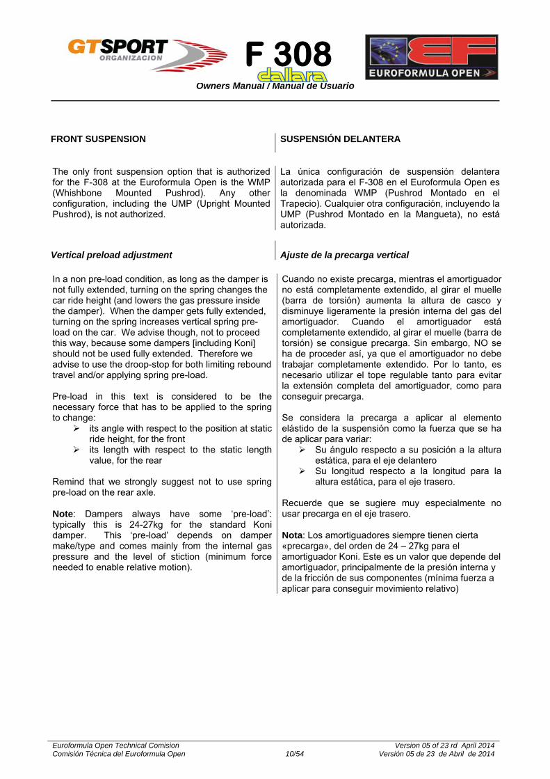
The only front suspension option that is authorized for the F-308 at the Euroformula Open is the WMP (Whishbone Mounted Pushrod). Any other configuration, including the UMP (Upright Mounted Pushrod), is not authorized.
La única configuración de suspensión delantera autorizada para el F-308 en el Euroformula Open es la denominada WMP (Pushrod Montado en el Trapecio). Cualquier otra configuración, incluyendo la UMP (Pushrod Montado en la Mangueta), no está autorizada.
In a non pre-load condition, as long as the damper is not fully extended, turning on the spring changes the car ride height (and lowers the gas pressure inside the damper). When the damper gets fully extended, turning on the spring increases vertical spring pre-load on the car. We advise though, not to proceed this way, because some dampers [including Koni] should not be used fully extended. Therefore we advise to use the droop-stop for both limiting rebound travel and/or applying spring pre-load. Pre-load in this text is considered to be the necessary force that has to be applied to the spring to change:
its angle with respect to the position at static ride height, for the front
its length with respect to the static length value, for the rear
Remind that we strongly suggest not to use spring pre-load on the rear axle. Note: Dampers always have some ‘pre-load’: typically this is 24-27kg for the standard Koni damper. This ‘pre-load’ depends on damper make/type and comes mainly from the internal gas pressure and the level of stiction (minimum force needed to enable relative motion).
Cuando no existe precarga, mientras el amortiguador no está completamente extendido, al girar el muelle (barra de torsión) aumenta la altura de casco y disminuye ligeramente la presión interna del gas del amortiguador. Cuando el amortiguador está completamente extendido, al girar el muelle (barra de torsión) se consigue precarga. Sin embargo, NO se ha de proceder así, ya que el amortiguador no debe trabajar completamente extendido. Por lo tanto, es necesario utilizar el tope regulable tanto para evitar la extensión completa del amortiguador, como para conseguir precarga. Se considera la precarga a aplicar al elemento elástido de la suspensión como la fuerza que se ha de aplicar para variar:
Su ángulo respecto a su posición a la altura estática, para el eje delantero
Su longitud respecto a la longitud para la altura estática, para el eje trasero.
Recuerde que se sugiere muy especialmente no usar precarga en el eje trasero. Nota: Los amortiguadores siempre tienen cierta «precarga», del orden de 24 – 27kg para el amortiguador Koni. Este es un valor que depende del amortiguador, principalmente de la presión interna y de la fricción de sus componentes (mínima fuerza a aplicar para conseguir movimiento relativo)

F 308
Owners Manual / Manual de Usuario
Euroformula Open Technical Comision Comisión Técnica del Euroformula Open 11/54
Version 05 of 23 rd April 2014 Versión 05 de 23 de Abril de 2014
PUSH ROD ADJUSTER
DROOP STOP
ROCKER Preload at the vehicle Precarga en el vehículo
To make the preload adjustment on the vehicle, proceed as follows:
Mount the damper-spring combination with the spring platform just in contact with the spring
Put the car including the driver on the set-up floor
Clear the droop-stop from touching the rocker
Adjust ride height with the pushrod adjusters to the desired setting (further correct for corner weights at this point)
Bring the droop-stop in contact with the rocker
Now turn the spring platform to achieve the desired pre-load
Para regular la precarga en el vehículo, proceder de la siguiente manera:
Montar el conjunto muelle-amortiguador con la tuerca justo en contacto con el muelle.
Montar en el coche el conjunto de muelle amortiguador y poner el coche con el piloto a bordo en el suelo plano.
Retirar el tope de extension hasta que deje de tocar con el balancín.
Ajustar los reglajes de altura de casco utilizando las regulaciones de los push-rods (ajustando los pesos por rueda).
Regular el tope de extensión hasta que toque con el balancín.
Girar la tuerca la tuerca de regulación del muelle hasta obtener la precarga deseada.

F 308
Owners Manual / Manual de Usuario
Euroformula Open Technical Comision Comisión Técnica del Euroformula Open 12/54
Version 05 of 23 rd April 2014 Versión 05 de 23 de Abril de 2014
Roll Center Centro de Balanceo
The Front roll centre height can be changed by moving the spacer relative to the wishbone spherical joint.
When using the low roll center position, the push-rod length has to be shortened by 1,2 register turns ( ≈ 7 face of the adjuster) to put the car back at the same front ride height.
When adjusting the roll centre height camber gain versus wheel travel varies a little
Please remember that the spacer is now of 6 mm., not as for the former vehicles, for which i twas of 5 mm.
La altura del centro de balanceo delantero puede regularse mediante los casquillos de posicionamiento de la rótula del triángulo de suspensión
Cuando se usa la posición baja del centro de balanceo, la longitud del push-rod tiene que acortarse aproximadamente en 1,2 vueltas del regulador (≈ 7 caras), para dejar el coche en la misma altura delantera.
Cuando se ajusta la altura del centro de balanceo, la variación de caída con la altura, varía ligeramente.
Tenga en cuenta que el espaciador es ahora de 6 mm, no como en los vehículos anteriores, que era de 5 mm.
OPTION / OPCIÓN
Ride Height / Altura de casco
Camber variation for 10 mm of wheel travel / Variación de caída
para 10mm de recorrido de rueda. Standard X 3’
Low / Baja -14 mm 5’

F 308
Owners Manual / Manual de Usuario
Euroformula Open Technical Comision Comisión Técnica del Euroformula Open 13/54
Version 05 of 23 rd April 2014 Versión 05 de 23 de Abril de 2014

F 308
Owners Manual / Manual de Usuario
Euroformula Open Technical Comision Comisión Técnica del Euroformula Open 14/54
Version 05 of 23 rd April 2014 Versión 05 de 23 de Abril de 2014
CASTOR ANGLE SETTING Front
AJUSTE DEL AVANCE Delantero
When the car is flat, that is with the same front and rear ride height:
Measure the apparent castor angle and compare this with the following: when the upright inclination angle (apparent castor) is +2.10° the castor angle (build in castor) is 10.60°. The upright reference plane points upwards in forward direction.
When the car has a pitch angle, that is with different front and rear ride height:
For instance, with FRH 15 mm and RRH 30mm the pitch angle equals:
[(30-15)/2730] x 57.29 = 0.31°
The upright inclination angle (apparent castor) is --2.10° + 0.31° = 2.41° and the castor angle (build in castor) becomes 10.60° - 0.31° = 10.29°
Cuando el vehículo está completamente plano, (altura de casco delantera y trasera iguales):
Medir el avance aparente y compararlo con lo siguiente: cuando la inclinación de la mangueta (avance aparente) es de +2.10º, el ángulo de avance (real) es de 10.60º. La referencia del plano de la mangueta es hacia delante.
Con alturas de casco diferentes en el eje delantero y en el eje trasero, el ángulo de avance varía debido al “cabeceo” del vehículo. Como valor de referencia, con 15 mm. de altura de casco delantera y 30 mm. de altura de casco trasera, el ángulo de cabeceo es : [(30-15)/2730] x 57.29 = 0.31°
Por tanto, el ángulo de inclinación de la mangueta (avance aparente) es +2.10° + 0.31° = 2.41° y el avance real es 10.60° - 0.31° = 10.29°
CASTOR /AVANCE 10.29°
HORIZONTAL MEASURED
ANGLE / ÁNGULO
MEDIDO 2.41°
TRAVEL DIRECTION /
DIRECCIÓN DE AVANCE
F 308
Owners Manual / Manual de Usuario
Euroformula Open Technical Comision Comisión Técnica del Euroformula Open 15/54
Version 05 of 23 rd April 2014 Versión 05 de 23 de Abril de 2014
Rear
Trasero
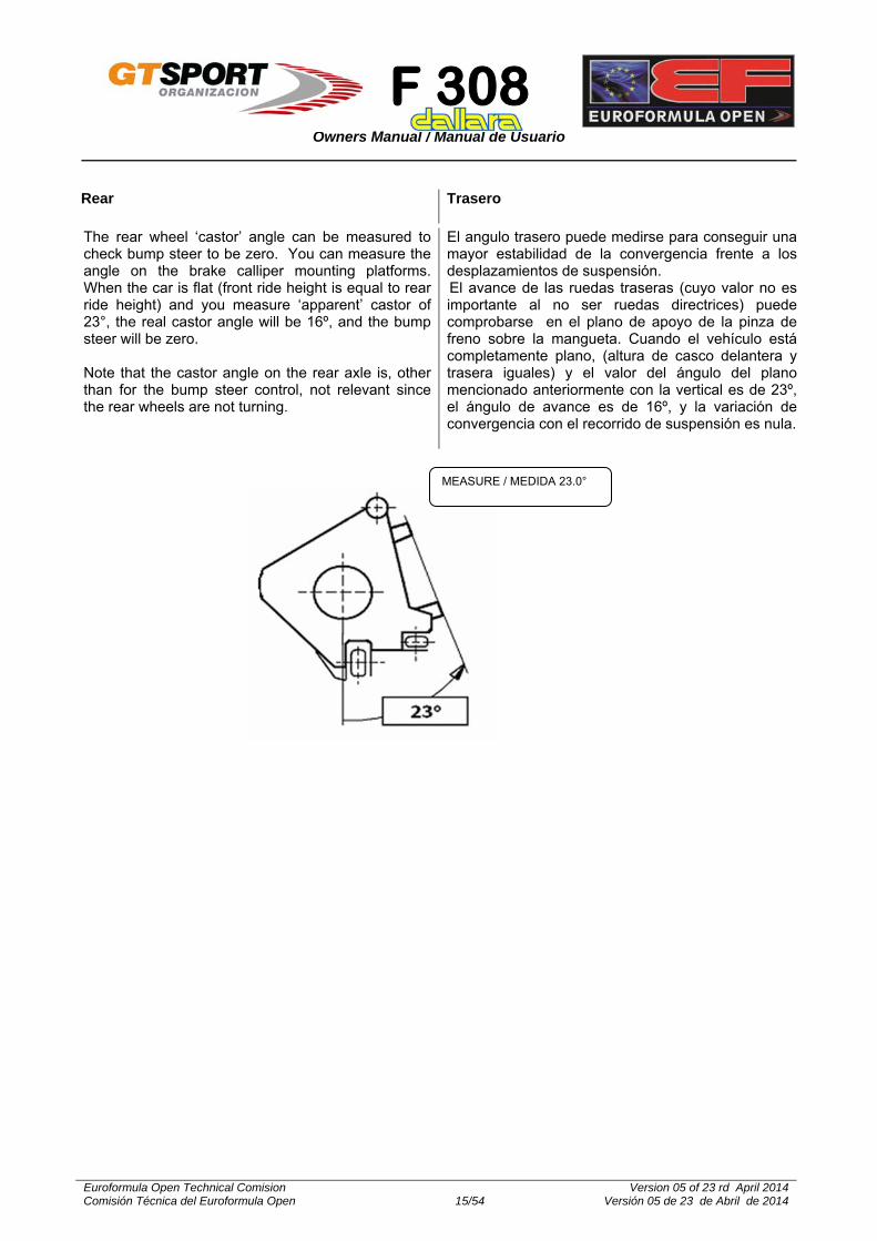
The rear wheel ‘castor’ angle can be measured to check bump steer to be zero. You can measure the angle on the brake calliper mounting platforms. When the car is flat (front ride height is equal to rear ride height) and you measure ‘apparent’ castor of 23°, the real castor angle will be 16º, and the bump steer will be zero. Note that the castor angle on the rear axle is, other than for the bump steer control, not relevant since the rear wheels are not turning.
El angulo trasero puede medirse para conseguir una mayor estabilidad de la convergencia frente a los desplazamientos de suspensión. El avance de las ruedas traseras (cuyo valor no es importante al no ser ruedas directrices) puede comprobarse en el plano de apoyo de la pinza de freno sobre la mangueta. Cuando el vehículo está completamente plano, (altura de casco delantera y trasera iguales) y el valor del ángulo del plano mencionado anteriormente con la vertical es de 23º, el ángulo de avance es de 16º, y la variación de convergencia con el recorrido de suspensión es nula.
MEASURE / MEDIDA 23.0°

F 308
Owners Manual / Manual de Usuario
Euroformula Open Technical Comision Comisión Técnica del Euroformula Open 16/54
Version 05 of 23 rd April 2014 Versión 05 de 23 de Abril de 2014
FRONT ANTI-ROLL
ANTIBALANCEO DELANTERO
STIFF SETTING
SOFT SETTING
Drawings shows both motion ratio’s
El dibujo muestra las dos posibles configuraciones
The TABLE below shows the motion ratios for all ARB’s and different blades available. RATIO = WHEEL/ARB [WHEEL vertical travel / ARB drop link travel]
La TABLA adjunta muestra las relaciones de movimiento para todas las barras estabilizadoras (ARB) y bieletas disponibles. RATIO = RUEDA/ARB [Mov. Vertical RUEDA / Mov. Bieleta ARB

F 308
Owners Manual / Manual de Usuario
Euroformula Open Technical Comision Comisión Técnica del Euroformula Open 17/54
Version 05 of 23 rd April 2014 Versión 05 de 23 de Abril de 2014
Blade Long / Longitud bieleta (mm) Soft Configuration / Configuracion blanda
Stiff configuration / Configuración rígida
270 1.187 0.998
245 1.207 1.012
221 1.227 1.027
170 1.272 1.058
115 1.324 1.093
Reglable ARB / Barra antibalanceo regulable
5 holes ARB / Barra5 Puntos
Soft Configuration / Configuracion blanda
Stiff configuration / Configuración rígida
1.276 1.059
1.295 1.073
1.315 1.087
1.336 1.102
1.357 1.108
7 Holes ARB / Barra7 Puntos
1.239 1.031
1.255 1.044
1.272 1.056
1.290 1.069
1.308 1.082
1.326 1.095
1345 1.109

F 308
Owners Manual / Manual de Usuario
Euroformula Open Technical Comision Comisión Técnica del Euroformula Open 18/54
Version 05 of 23 rd April 2014 Versión 05 de 23 de Abril de 2014
ARB / Barra Blade / Cuchilla Position / Posicion
T-13
Solid / Maciza
270 mm
1 2 3 4 5
3,0 3.1 3.4 3.9 4.0
245 mm 3.8 3.9 4.2 4.7 4.8
221 mm 5.0 5.1 5.4 5.9 6.0
170 mm 10.00 10.2 10.7 11.4 11.6
115 mm x x x x x
ARB / Barra Blade / Cuchilla Position / Posicion
T-18x2.5
270 mm
1 2 3 4 5
5.5 6.0 7.1 9.4 10.0
245 mm 6.9 7.4 9.0 11.1 11.8
Soft configuration:
Use the fixation point close to the rocker axle. For a given ARB travel the WHEEL must travel more compared with the STIFF SETTING
Stiff configuration:
Use the fixation point further away from the rocker axle for a given ARB travel the WHEEL will travel less compared with the SOFT SETTING
Configuración blanda:
Usar el punto de fijación cercano al eje del balancín. Para un desplazamiento determinado de la ARB, la RUEDA ha de desplazarse más que en la configuración RÍGIDA.
Configuración rígida:
Usar el punto de fijación más lejado del eje del balancín. Para un desplazamiento determinado de la ARB, la RUEDA ha de desplazarse menos que en la configuración RÍGIDA.
Front ARB values
Valores barra (ARB) delantera
The values shown below are in kg/mm [daN/mm] at one end of the blade while the other end is locked. The values below are measured on the ARB isolated from the car. You may use the Motionat ground Ratio to calculate the ARB stiffness. On various ARBs we suggest not to use the 115mm blade.
Los valores que se muestran a continuación son en kg / mm [daN / mm] en un extremo de la cuchilla, mientras que el otro extremo está bloqueado. Los valores a continuación se miden con la ARB (barra) desmontada del coche. Se puede utilizar la relación de movimiento para calcular la rigidez de la barra (ARB) En varias barras le sugerimos no utilizar la cuchilla de 115mm

F 308
Owners Manual / Manual de Usuario
Euroformula Open Technical Comision Comisión Técnica del Euroformula Open 19/54
Version 05 of 23 rd April 2014 Versión 05 de 23 de Abril de 2014
221 mm 9.5 10.1 11.8 14.2 15.0
170 mm 21.0 22.2 25.7 30.5 32.0
115 mm x x x x x
ARB / Barra Blade / Cuchilla Position / Posicion
T-20x2.0
270 mm
1 2 3 4 5
6.5 7.1 8.7 10.8 11.5
245 mm
8.0 8.6 10.4 12.7 13.5
221 mm 11.0 11.8 13.5 17.0 18.0
170 mm 24.0 25.3 28.9 33.9 35.5
115 mm x x X x X
ARB / Barra Blade / Cuchilla Position / Posicion
T-30x5.0
270 mm
1 2 3 4 5
8.5 10.7 17.1 25.7 28.5
245 mm
11.1 13.8 21.7 32.3 35.8
221 mm 16.0 19.4 29.3 42.7 47.0
170 mm 41.5 48.8 66.2 91.0 99.0
115 mm 187.0 190.0 198.5 210.0 213.8
F 308
Owners Manual / Manual de Usuario
Euroformula Open Technical Comision Comisión Técnica del Euroformula Open 20/54
Version 05 of 23 rd April 2014 Versión 05 de 23 de Abril de 2014
STEERING
DIRECCIÓN
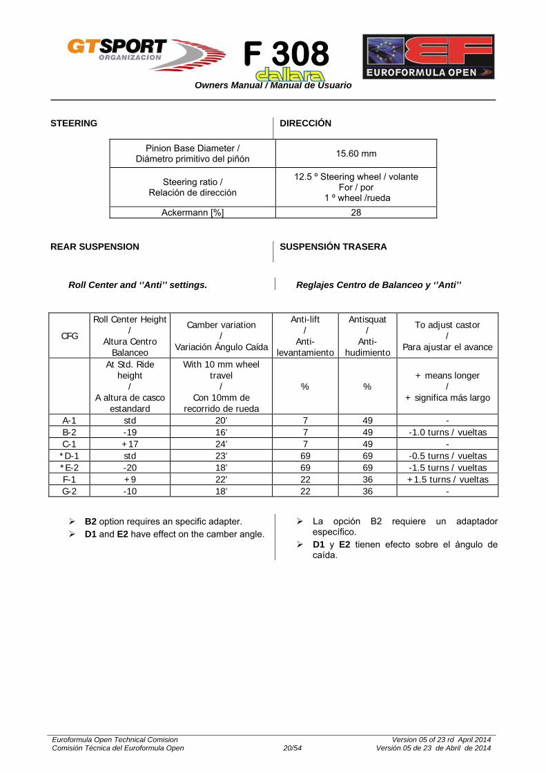
Pinion Base Diameter / Diámetro primitivo del piñón
15.60 mm
Steering ratio / Relación de dirección
12.5 º Steering wheel / volante For / por
1 º wheel /rueda
Ackermann [%] 28
REAR SUSPENSION
SUSPENSIÓN TRASERA
CFG
Roll Center Height /
Altura Centro Balanceo
Camber variation /
Variación Ángulo Caída
Anti-lift /
Anti-levantamiento
Antisquat /
Anti-hudimiento
To adjust castor /
Para ajustar el avance
At Std. Ride height
/ A altura de casco
estandard
With 10 mm wheel travel
/ Con 10mm de
recorrido de rueda
% % + means longer
/ + significa más largo
A-1 std 20’ 7 49 - B-2 -19 16’ 7 49 -1.0 turns / vueltas C-1 +17 24’ 7 49 - *D-1 std 23’ 69 69 -0.5 turns / vueltas *E-2 -20 18’ 69 69 -1.5 turns / vueltas F-1 +9 22’ 22 36 +1.5 turns / vueltas G-2 -10 18’ 22 36 -
Roll Center and ‘’Anti’’ settings. Reglajes Centro de Balanceo y ‘’Anti’’
B2 option requires an specific adapter. D1 and E2 have effect on the camber angle.
La opción B2 requiere un adaptador específico.
D1 y E2 tienen efecto sobre el ángulo de caída.

F 308
Owners Manual / Manual de Usuario
Euroformula Open Technical Comision Comisión Técnica del Euroformula Open 21/54
Version 05 of 23 rd April 2014 Versión 05 de 23 de Abril de 2014

F 308
Owners Manual / Manual de Usuario
Euroformula Open Technical Comision Comisión Técnica del Euroformula Open 22/54
Version 05 of 23 rd April 2014 Versión 05 de 23 de Abril de 2014
REAR ANTI-ROLL BAR
BARRA ANTI-BALANCEO TRASERA
Ø 13 Ø 14 Ø 16 Ø 19 Ø 21 Ø 22 Ø 24 Ø26/30*
Ø 28 Ø 30 Ø 35 Ø 40
P1-P1 15.7 19.9 29.4 44.6 53.8 57.8 65.0 70.6 75.1 78.7 84.5 87.7
1-2 15.8 20.2 30.0 45.9 55.7 60.1 67.9 74.1 79.0 83.0 89.5 93.0
2-2 16.0 20.4 30.6 47.4 57.8 62.5 71.0 77.8 83.3 87.7 95.0 99.0
1-3 16.3 20.8 31.5 49.5 61.1 66.3 76.0 83.8 90.2 95.5 104.1 108.9
2-3 16.4 21.1 32.1 51.2 63.6 69.3 80.0 88.7 95.8 101.8 111.7 117.3
1-4 16.7 21.5 33.1 53.7 67.6 74.1 86.3 96.6 105.1 112.3 124.5 131.4
1-5* 16.9 21.8 33.8 55.7 70.7 77.8 91.5 103.1 112.8 121.2 135.5 143.8
2-5 17.0 22.1 34.6 57.8 74.1 82.0 97.3 110.5 121.8 131.6 148.7 158.7
3-4 17.3 22.6 35.7 61.0 79.6 88.7 106.9 123.0 137.2 149.8 172.3 185.9
3-5 17.5 22.9 36.6 63.5 83.9 94.2 114.9 133.8 150.7 166.0 194.2 211.5
4-4 17.8 23.4 37.9 67.5 91.0 103.1 128.4 152.5 174.9 195.8 236.3 262.5
4-5 18.0 23.8 38.8 70.6 96.7 110.5 140.2 169.3 197.5 224.5 279.4 316.8
5-5 18.2 24.2 39.8 74.0 103.2 119.1 154.3 190.4 226.7 263.1 341.7 399.4
The F-308 is equipped with two reglable linkages (of 80 mm lenght) for the rear anti-roll bar.
Among the available bars, the 40 mm.one is the hardest, and the 13 mm one the softest.
The next table shows, at the first row, the position of the linkages of the anti-roll bar, considering that 1 correspond to the softest position, and 5 to the stiffest one.
The ARB that is considerd as standard is the 26 mm one, which is equivalent to the 30 x 3 one.
Concerning to the position of the linkages, P1-P5 = P3-P3 = P2-P4.
Values in Kg / mm. One blade is fixed, and the other displaces 1 mm.
All the bars authorized with the F-305 can be used with the F-308.
El F-308 está equipado con dos bieletas regulables (de 80 mm de longitud) para la barra estabilizadora trasera.
La barra más rígida de las disponibles es la de 40 mm. de diámetro y la de 13 mm la menos rígida.
En la tabla siguiente, los números de la primera fila representan la posición de las bieletas (cuchillas) de la barra estabilizadora, teniendo en cuenta que 1 corresponde al reglaje más blando y 5 al reglaje más rígido.
La barra estabilizadora que se considera estándar es la de 26mm. de diámetro, que equivale a la de 30 x 3.
En cuanto a las bieletas, P1-P5 = P3-P3 = P2-P4.
Valores en Kg/mm, para una bieleta fija y la otra con 1 mm de desplazamiento.
Todas las barras autorizadas para el F-305, están autorizadas en el F-308
F 308
Owners Manual / Manual de Usuario
Euroformula Open Technical Comision Comisión Técnica del Euroformula Open 23/54
Version 05 of 23 rd April 2014 Versión 05 de 23 de Abril de 2014
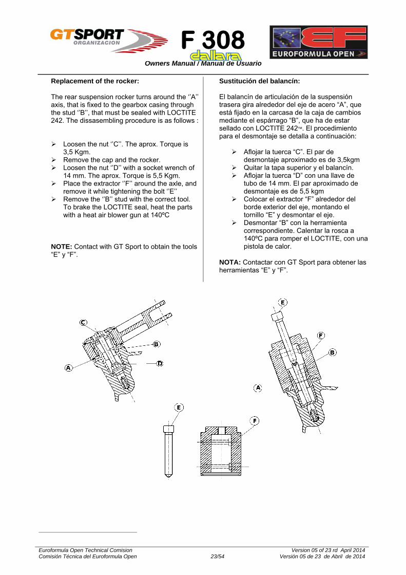
Replacement of the rocker: The rear suspension rocker turns around the ‘’A’’ axis, that is fixed to the gearbox casing through the stud ‘’B’’, that must be sealed with LOCTITE 242. The dissasembling procedure is as follows :
Loosen the nut ‘’C’’. The aprox. Torque is
3,5 Kgm. Remove the cap and the rocker. Loosen the nut ‘’D’’ with a socket wrench of
14 mm. The aprox. Torque is 5,5 Kgm. Place the extractor ‘’F’’ around the axle, and
remove it while tightening the bolt ‘’E’’ Remove the ‘’B’’ stud with the correct tool.
To brake the LOCTITE seal, heat the parts with a heat air blower gun at 140ºC
NOTE: Contact with GT Sport to obtain the tools “E” y “F”.
Sustitución del balancín: El balancín de articulación de la suspensión trasera gira alrededor del eje de acero “A”, que está fijado en la carcasa de la caja de cambios mediante el espárrago “B”, que ha de estar sellado con LOCTITE 242. El procedimiento para el desmontaje se detalla a continuación:
Aflojar la tuerca “C”. El par de desmontaje aproximado es de 3,5kgm
Quitar la tapa superior y el balancín. Aflojar la tuerca “D” con una llave de
tubo de 14 mm. El par aproximado de desmontaje es de 5,5 kgm
Colocar el extractor “F” alrededor del borde exterior del eje, montando el tornillo “E” y desmontar el eje.
Desmontar “B” con la herramienta correspondiente. Calentar la rosca a 140ºC para romper el LOCTITE, con una pistola de calor.
NOTA: Contactar con GT Sport para obtener las herramientas “E” y “F”.

F 308
Owners Manual / Manual de Usuario
Euroformula Open Technical Comision Comisión Técnica del Euroformula Open 24/54
Version 05 of 23 rd April 2014 Versión 05 de 23 de Abril de 2014
DIFFERENTIAL
DIFERENCIAL
This differential is designed with versatility as its major asset. Many parameters will lead you to the required setting. A car with good grip and limited power requires a very different arrangement than that required for a high poor grip/high power car.
Working principles: Ten friction plates within the diff, six connected to the side gears, four to the diff casing, control the amount of ‘differential’ action. The amount of limited slip only depends on the friction force between these ten plates.
Four factors contribute to the level of this friction force:
1. The bevel gears thrust apart as soon as the car moves. This is a feature of bevel gears and is not adjustable. The contribution of this on friction is minimal.
2. The ramp angle on the side gear ring influences the amount of the driving force on the diff that gets directed sideways and onto the plates. E.g. on the power/drive side ramp, 60 degrees transmits less force sideways than a 30 degree ramp. Likewise, on the off-power side ramp, an 80 degrees angle will transmit little force while 45 degrees locks more. 60°/80° is fitted as standard;
3. The pre-load with which they are assembled to start. In each diff there is a pre-load spacer that looks like one of the B plates, but thicker. Its thickness dictates to what degree the plates are pre-loaded / forced against each other. The pre-load is set and checked on each diff by holding one side gear locked, via a dummy output shaft locked in a vice, and by turning the other with a torque wrench. If the measured resistance is deemed too high, the spacer is ground down until the desired figure is achieved. The preload should be checked periodically as it tends to reduce as the diff runs, meanwhile a slightly thicker spacer will allow re-setting;
4. The re-arrangement of the order of the friction discs. The arrangement 1, with a disc succession A, B, A, B, A, has the maximum number of working friction faces. It gives the maximum resisting torque. The arrangement 3 has the minimum of working friction faces and gives the minimum resisting torque.
Las posibilidades de regulación del diferencial del F-308 son muy elevadas. Un vehículo que disponga de buen grip y baja potencia requiere un reglaje de diferencial completamente diferente al de un vehículo con mal grip y alta potencia.
Principio de funcionamiento: Un total máximo de diez discos de fricción en el interior del diferencial, seis de ellos conectados a los planetarios (3 a cada uno de ellos) y cuatro conectados a la carcasa del diferencial, permiten controlar el par que se transmite a ambas ruedas motrices. El grado de deslizamiento depende de la fricción entre los discos.
En definitiva, el nivel de esta fuerza de fricción, depende de cuatro factores:
1. Los satélies tienden a separarse tan pronto como el coche comienza a moverse. Este efecto no es ajustable, y su contribución a la fricción es mínima.
2. El ángulo de las semi-coquillas del diferencial determina, en función del par total transmitido, el esfuerzo axial de apriete de los discos de fricción. Por ejemplo, una rampa de 60º genera menos esfuerzo lateral sobre los discos de fricción que una rampa de 30º. Las rampas más utilizadas en éste vehículo y que se pueden tomar como reglaje inicial o de referencia son las de 60º en la parte de aceleración y de 80º en la parte de retención.
3. La precarga de montaje. El valor de la precarga es regulable en función de la anchura de las arandelas “B”, teniendo en cuenta que a mayor espesor, mayor precarga. Para comprobar el valor de la precarga, es necesario introducir un extremo de estriado de transmisión en el interior de uno de los planetarios con el diferencial montado y lubricado con el aceite que se vaya a utilizar en la caja de cambios y, con una llave dinamométrica, comprobar cuál es el valor de par con el que el planetario comienza a girar. Se ha de comprobar cada cierto tiempo, ya que tiende a disminuir con el uso.
4. El lay-out de montaje de los discos. El montaje 1, con una sucesión de discos A, B, A, B, A, tiene el máximo número de caras de fricción, y proporciona el mayor par de fricción. El lay-out 3 tiene el menor número de caras de fricción, y proporciona el menor par resistente.

F 308
Owners Manual / Manual de Usuario
Euroformula Open Technical Comision Comisión Técnica del Euroformula Open 25/54
Version 05 of 23 rd April 2014 Versión 05 de 23 de Abril de 2014
LOCK % 2.5 5.0 7.0 9.5 11 12 15.5 18 24 25 33.5 42 44 55 68.5
Standard Hewland available ramp angles are: 30/60; 45/45; 45/80; 60/80; 80/80; optional: 80/90 and those including 70°
Differential settings have an important influence on the car’s balance throughout the corner. Also handling is affected, especially so on corner turn-in and exit.
The torque on the differential in drive (acceleration) is much bigger than the torque on the differential given by the engine brake (deceleration). Typical in line acceleration gets to about 1g starting from a relatively low speed, off-power/braking by the engine only gets typically up to 0.3g.
The disc configuration (2, 4 or 6 faces) has the same effect on drive and off-power, the ramps are the only tool to differentiate the friction force or ‘lock’ between drive and brake.
The discs wear off, just as a clutch, and should get checked regularly. This also means that the pre-load is ‘wearing’ down, faster so when using the 2 friction discs configuration and significantly less when using 6 friction faces.
Pre-load is kind of a ‘constant lock’ and the effect is felt in slow and fast corners in entry, mid-corner and exit. The ramps and disc configurations typically have more effect in slow and less in fast corners, and affect corner entry and exit, less so mid-corner.
Pre-load locks the differential (both wheels turn at the same speed) until the difference in torque is higher than the pre-load. Once passed the pre-load, the remaining lock is achieved by the ramps and disc configuration mainly.
Most circuits require little lock to prevent the inner wheel from spinning coming out of corners, depending though on tyres, track, driving style and weather conditions. Excessive lock might result in power under-steer.
Some amount of lock in off-power helps to stabilize the rear end, excessive lock might cause turn-in under-steer.
Las rampas disponibles de Hewland son: 30/60, 45/45; 45/80; 60/80; 80/80, opcional: 80/90, y las que incluyen 70º.
El reglaje del diferencial influye mucho sobre la puesta a punto del vehículo, especialmente en la entrada y salida de las curvas.
El par en el diferencial en aceleración es mucho mayor que el par del diferencial en retención (par de bombeo del motor). En aceleración, el valor típico está en torno a 1 g a baja velocidad, mientras que en retención el valor es únicamente del orden de 0.3 g.
La configuración de los discos (2, 4 o 6 caras) tiene el mismo efecto en aceleración y en retención, por lo que el ángulo de las rampas es el único parámetro para diferenciar las fuerzas en aceleración y en retención.
Como ocurre en un embrague, los discos se desgastan, y han de revisarse regularmente. Esto también significa que la precarga va disminuyendo, tanto más cuanto mayor es el número de caras de fricción.
La pregarga se puede considerar como una fuerza de fircción constante, y el efecto se nota especialmente en la entrada, parte media y salida de las curvas, tanto lentas como rápidas.Las rampas y el número de caras de fricción tienen mayor efecto en las curvas lentas, y afecta sobre todo en la entrada y en la salida (no tanto en la zona media)
La precarga mantiene ambas ruedas girando a la misma velocidad, hasta que el par en el diferencial es superior a la precarga. Una vez superada la precarga, el grado de bloqueo está determinado por las rampas y la configuración de los discos.
En casi todos los circuitos, se requiere poco bloqueo para evitar la aceleración de la rueda interior a la salidad de las curvas, dependiendo, eso sí, de la pista, el piloto, etc. Un exceso de bloqueo se traduce en subviraje al acelerar.
Algo de bloqueo en retención ayuda a estabilizar el eje trasero, pero un bloqueo escesivo puede generar subviraje en la zona media de la curva.
F 308
Owners Manual / Manual de Usuario
Euroformula Open Technical Comision Comisión Técnica del Euroformula Open 26/54
Version 05 of 23 rd April 2014 Versión 05 de 23 de Abril de 2014
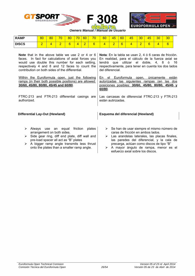
RAMP 80 80 70 80 70 60 70 60 45 60 45 30 45 30 30
DISCS 2 4 2 6 4 2 6 4 2 6 4 2 6 4 6
Differential Lay-Out (Hewland)
Esquema del diferencial (Hewland)
Note that in the above table we use 2 or 4 or 6 faces. In fact for calculations of axial forces you would use double this number for each setting, respectively 4 and 8 and 12 faces to count the contribution on both sides of the differential. Within the Euroformula open, just the following ramps (in their both possible positions) are allowed: 30/60, 45/80, 80/80, 45/45 and 60/80. FTRC-213 and FTR-213 differential casings are authorized.
Nota: En la tabla se usan 2, 4 ó 6 caras de fricción. En realidad, para el cálculo de la fuerza axial se tendrá que utilizar el doble, 4, 8 ó 16 respectivamente, para tener en cuenta los dos lados del diferencial. En el Euroformula open, únicamente están autorizadas las siguientes rampas (en las dos posiciones posibles: 30/60, 45/80, 80/80, 45/45 y 60/80. Las carcasas de diferencial FTRC-213 y FTR-213 están autirizadas.
Always use an equal friction plates arrangement on both sides.
Side gear ring, diff end plate, diff wall and pre-load spacer all act as “B” plates
A bigger ramp angle transmits less thrust onto the plates than a smaller ramp angle.
Se han de usar siempre el mismo número de caras de fricción en ambos lados.
Las arandelas laterales, las placas finales, las paredes del diferencial, y la cala de precarga, actúan como discos de tipo “B”
A mayor ángulo de rampa, menor es el esfuerzo axial sobre los discos.

F 308
Owners Manual / Manual de Usuario
Euroformula Open Technical Comision Comisión Técnica del Euroformula Open 27/54
Version 05 of 23 rd April 2014 Versión 05 de 23 de Abril de 2014
The following parts are authorized: Lightened differential casing (FTRL 213), and differential cover (FTRL 214).
Se autorizan las siguientes piezas: Carcasa de diferencial (FTRL 213) y tapa de diferencial (FTRL 214).

F 308
Owners Manual / Manual de Usuario
Euroformula Open Technical Comision Comisión Técnica del Euroformula Open 28/54
Version 05 of 23 rd April 2014 Versión 05 de 23 de Abril de 2014
DAMPERS
AMORTIGUADORES
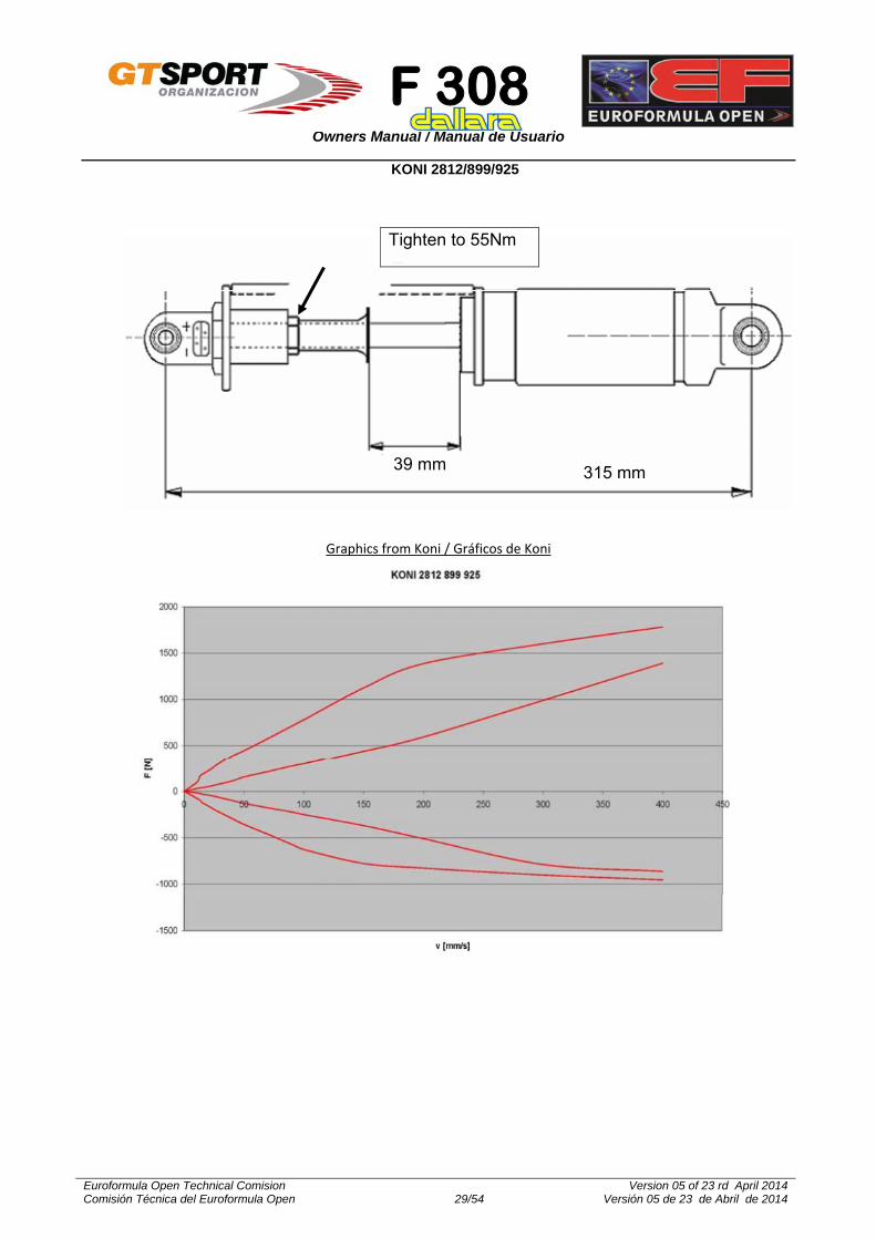
General information. Dimensions Información general. Dimensiones
DIMENSIÓNS (Front & Rear) mm
Totaly extended lenght
/
Long. Total extendido
315
Totaly compressed lenght
/
Long. Total comprimido
276
Total Stroke
/
Carrera total
39
The only authorized dampers for the F-308 within the Euroformula Open are the KONI 2812-899-925.
Both, the front and rear dampers, have the same piston, shims and valves configuration, the same dimensions, and the same fitting parts.
The damper preload is aprox. 8-9 kg, due to the internal gas pressure.
The main dimensions are shown in the following table.
Los únicos amortiguadores autorizados para el F-308, en el Euroformula Open, son los KONI 2812-899-925.
Los amortiguadores traseros y el delantero tienen la misma configuración de pistón, chapas y válvulas, la misma longitud total (completamente extendidos) y las mismas piezas para su instalación.
La precarga del amortiguador es aproximadamente, de 8-9 kg, debido a la presión interna del gas.
Las dimensiones principales de los mismos se muestran en la siguiente tabla.
F 308
Owners Manual / Manual de Usuario
Euroformula Open Technical Comision Comisión Técnica del Euroformula Open 29/54
Version 05 of 23 rd April 2014 Versión 05 de 23 de Abril de 2014
KONI 2812/899/925
39 mm 315 mm
Tighten to 55Nm
Graphics from Koni / Gráficos de Koni

F 308
Owners Manual / Manual de Usuario
Euroformula Open Technical Comision Comisión Técnica del Euroformula Open 30/54
Version 05 of 23 rd April 2014 Versión 05 de 23 de Abril de 2014
AERODINAMICS
AERODINÁMICA
Front Wing
Alerón delantero
The only authorized front wing configuration for the F-308 at the Euroformula Open is the medium and high downforce one.
For this configuration, the standard one, the main plain is supposed to be set at -0,6º from the car’s floor.
The references for the setting holes are shown at the picture.
La única configuración aerodinámica delantera autorizada para el F-308 en el Euroformula Open es la de media y alta carga.
Para esta configuración, el plano principal se puede considerar que forma un ángulo de 0,6º respecto del plano inferior del vehículo.
En la figura se muestran las referencias de los orificios de reglaje.

F 308
Owners Manual / Manual de Usuario
Euroformula Open Technical Comision Comisión Técnica del Euroformula Open 31/54
Version 05 of 23 rd April 2014 Versión 05 de 23 de Abril de 2014
Rear Wing
Alerón trasero
The only non authorized Dallara rear wing configuration for the F-308 at the Euroformula Open is the medium downforce one.
The only authorized rear wing support for the F-308 at the Euroformula Open is the F308 05 A 004
Pictures show all the profiles and the possible configurations from Dallara.
The setting holes references are also shown.
La única configuración aerodinámica trasera de Dallara no autorizada para el F-308 en el Euroformula Open es la de media carga.
El único soporte autorizado para el ala trasera del F-308 en el Euroformula Open es el F308 05 A 004
En las figuras se muestran todos los perfiles y configuraciones disponibles de Dallara.
También se muestran las referencias de los orificios de regulación.
LDF MDF HDF
LOW DOWNFORCE MID DOWNFORCE HIGH DOWNFORCE
(Baja sustentación) (Sustentación Media) (Sustentación Alta)
Profiles /Perfiles
Aerodinamic configurations
Configuraciones aerodinámicas

F 308
Owners Manual / Manual de Usuario
Euroformula Open Technical Comision Comisión Técnica del Euroformula Open 32/54
Version 05 of 23 rd April 2014 Versión 05 de 23 de Abril de 2014
The front wing angle is measured at its top part, inside the gurney.
The correspondence between the fixation holes and the inclination angle is just an indication, since this angle also depends on the front and rear riding heights.
The lateral plates fixation holes allow
adjustments of, aprox, 1º of the inclination angle.
El ángulo del perfil delantero se mide en la parte superior del mismo, en el interior del Gurney.
La correspondencia entre los agujeros de fijación y el ángulo de incidencia es
lturas e, ya que el ángulo del ala es también alturas de las alturas de casco delantera y trasera.
Los taladros de las placas laterales permiten ajustes de aproximadamente 1º en el ángulo de incidencia.
Front Wing / Ala Delantera
Sta ndarD A B C D E F G
1 10° 11° 12° 13° 14° 15° 16° 2 17° 18° 19° 20° 21° 22° 23° 3 24° 25° 26° 27° 28° 29° 30° 4 31° 32° 33° 34° 35° 36° 37°
Rear Wing / Ala Trasera
LOWER WING / PERFIL INFERIOR MIN MAX Only with Standar supports
/ Sólo con soportes Estandar LOW DOWNFORCE -1° 10°
For the F308, within the Euroformula open, just the HDF (High Down Force) and LDF (Low Down Force) rear profiles are autorized
1. When fitting the LDF option (LDF plan F308 05C 001, Left lateral adjustment plate F308 05C 009, and Right lateral adjustment plate F308 05C 010), it is allowed either to fit or not the front flaps.
2. When this option is installed, it is possible to keep or to remove the standar gurney, but it is NOT authorized to change the standard gurney for another one.
3. The rear floor must always remain STD (without any modification).
4. The rear LDF lateral plates are NOT authorized.
Para el F308, en el Euroformula open, únicamente están autorizadas las alas traseras HDF (Alta carga) y LDF (Baja carga)
1. Cuando se monte la opción LDF, (Plano LDF F308 05C 001, Placa de ajuste lateral izquierda F308 05C 009, and Placa de ajuste lateral derecho F308 05C 010) es posible dejar o quitar los flaps delanteros.
2. Cuando se instale esta configuración, se podrá mantener o eliminar el gurney standard, NO permitiéndose sustituir el gurney estándar por otro.
3. El suelo trasero debe permanecer siempre STD (sin modificación).
4. Las placas laterales de soporte del perfil LDF no están autorizadas.

F 308
Owners Manual / Manual de Usuario
Euroformula Open Technical Comision Comisión Técnica del Euroformula Open 33/54
Version 05 of 23 rd April 2014 Versión 05 de 23 de Abril de 2014
TOP WING / PERFIL SUPERIOR LDF
A B C D E F 1 0º 1º 2º 3º 4º 5º 2 6º 7º 8º 9º 10º 11º
HDF
A B C D E F 1 2° 3° 4° 5° 6° 7° 2 8° 9° 10° 11° 12° 13° 3 14° 15° 16° 17° 18° 19° 4 20° 21° 22° 23° 24° 25°
Suggested aero settings / Reglajes aerodinámicos recomendados
CONF.
REAR / TRASERO FRONT / DELANTERO
CONF. TOP WING /
ALA SUPERIOR
TOP SETTING /
REGLAJE SUPERIOR
LOW WING /
ALA INFERIOR
FLAP TYPE
/ TIPO FLAP
FLAP SETTING
/ REGLAJE
FLAP
MAIN PLAIN /
PLANO PRINCIPAL
1 LDF 1º 1º NONE -0.6º 1
7 HDF 9º 7º SF 17º -0.6º 7
8 HDF 13º 12º SF 23º -0.6º 8
9 HDF 17º 12º SF 26º -0.6º 9
10 HDF 19º 14º SF 29º -0.6º 10
BALANCE [in % front] 39% 40%
Polar chart
Diagrama polar

F 308
Owners Manual / Manual de Usuario
Euroformula Open Technical Comision Comisión Técnica del Euroformula Open 34/54
Version 05 of 23 rd April 2014 Versión 05 de 23 de Abril de 2014
HOW TO BALANCE +1° FRONT FLAP / EQUILIBRADO DE +1º DEL FLAP DELANTERO
When rear wing in configuration: / En la configuración trasera:
HDF LDF
The angle is relative to the reference plane with zero rake, measured on the upper surface at the inboard side, without Gurney.
The optimum setting of the front wing for most of the possible configurations is -0,6 º. Whatever modification on the chasis, will affect these values.
The rear top wing inclination angle is the one
that is measured, referenced to the main reference chassis plan, between the top front part of the wing profile, and its the read edge. Whatever modification on the chasis, will affect these values.
Front and rear riding heights are critical for the correct aero balance of the vehicle and, consequently, for the performances. It is very important to consider the differences between the static values, and those on the track.
El ángulo expresado es relativo al plano de referencia con cero “rake”, medido en la superficie superior, en el lado interior, sin Gurney.
El reglaje óptimo para el perfil delantero para la mayoría de los reglajes posibles es de –0.6º. Cualquier variación en el chasis, alterará los valores anteriores.
La inclinación del conjunto aerodinámico superior del ala trasera es el ángulo, en relación al plano de referencia del chasis, medido entre la parte delantera superior del perfil y el borde trasero del mismo. Cualquier variación en el chasis, alterará los valores anteriores.
Los reglajes de las alturas de casco delantera y trasera son fundamentales para el correcto equilibrio aerodinámico del vehículo y, en definitiva, para sus prestaciones. Es importante tener en cuenta las diferencias entre los valores medidos en estático y los valores dinámicos en pista.
Balance of the car
Equilibrado del coche

F 308
Owners Manual / Manual de Usuario
Euroformula Open Technical Comision Comisión Técnica del Euroformula Open 35/54
Version 05 of 23 rd April 2014 Versión 05 de 23 de Abril de 2014
adjustments
Top rear wing / Perfil superior trasero
1,3 Hole/ Agujeros
0,9 Hole/ Agujeros
Front ride height / Altura delantera
+1,2 mm + 0,5 mm
Rear ride height / Altura trasera
‐ 1,9 mm ‐ 1,4 mm

F 308
Owners Manual / Manual de Usuario
Euroformula Open Technical Comision Comisión Técnica del Euroformula Open 36/54
Version 05 of 23 rd April 2014 Versión 05 de 23 de Abril de 2014
Front Blanking /Tapado delantero
CONFIGURACION EQUIVALENT INCREASE IN REAR HDF WING INCIDENCE
no blanking Referencia
30% front blanking +0.5°
(in order to re-balance you should reduce the rear wing incidence by 0.5°)
50% front blanking +1°
(in order to re-balance you should reduce the rear wing incidence by 1°)
Rear Top Blanking / Tapado superior trasero
CONFIGURACION EQUIVALENT INCREASE IN REAR HDF WING INCIDENCE
25% rear top blanking Reference
Cooling Blanking
Regulación de aire de refrigeración
Depending on ambient temperature, and required engine coolant temperature, it can be necessary to adjust the capacity of the coolers.
The cooling eficiency is increased by sealing any leak of the cooling ducts to the coolers.
Front blanking has both effect on cooling and on the car’s aerodynamic efficiency, as is shown at the following table.
The only authorized way to adjust the cooling blanking is using adhesive tape.
Early April 2012 the FIA recommended a different approach to blanking through blanking of the radiators directly rather than the intake or exit of side pods. Within the Euroformula Open, both solutions are autorized.
Dependiendo de la temperatura ambiente y la temperatura del agua requerida por el fabricante del motor puede necesitarse ajustar la capacidad de los radiadores de refrigeración.
La eficiencia de la refrigeración se incrementa sellando cualquier fuga eventual en los conductos de admission de los radiadores.
Tapar las entradas de agua incrementa la aerodinámica trasera y delantera, tal como se muestra en la table siguiente.
El único método autorizado para el reglaje de refrigeración es utilizar cinta adehesiva.
Recientemente, en Abril 2012, la FIA ha recomendado que la regulación de la entrada de aire se realice mediante el tapado de los radiadores y no de las entradas y salidas de los pontones. En el Euroformula Open, ambas posibilidades están autorizadas.

F 308
Owners Manual / Manual de Usuario
Euroformula Open Technical Comision Comisión Técnica del Euroformula Open 37/54
Version 05 of 23 rd April 2014 Versión 05 de 23 de Abril de 2014
50% rear top blanking
+0.5° (in order to re-balance you should reduce the rear wing
incidence by 0.5°)
75% rear top blanking +1°
(in order to re-balance you should reduce the rear wing incidence by 1°)
Without rear top blanking
-0.5° (in order to re-balance you should increase the rear wing
incidence by 0.5°)
Louvers / Aletas
Louver EQUIVALENT INCREASE IN REAR HDF WING INCIDENCE
Off Reference
On +1°
(in order to re-balance you should reduce the rear wing incidence by 1°)

F 308
Owners Manual / Manual de Usuario
Euroformula Open Technical Comision Comisión Técnica del Euroformula Open 38/54
Version 05 of 23 rd April 2014 Versión 05 de 23 de Abril de 2014
UPRIGHTS
MANGUETAS
Security advise: The uprights are homologated parts and
cannot be modified.
Aviso de seguridad Las manguetas son piezas homologadas y
NO puede modificarse ninguna de sus piezas.
Bearing removal: Remove the spigot unscrewing the six A nuts..
Remove the retainer using two M6x100 bolts at the “B” threaths
Remove the seeger “C”
Extract the bearing from the upright.
Remove the drive flange using two M6x100 bolts at the “B” threaths.
Desmontaje del rodamiento: Desmontar el centrador quitando las seis
tuercas A
Extraer el semi-buje externo utilizando dos tornillos M6x100 en las roscas “B”.
Retirar el circlip “C”.
Extraer el rodamiento de la mangueta.
Extraer el semi-buje interior utilizando dos tornillos M6x100 en las roscas “B”.
Bearing Assembly: Press the bearing into the retainer.
Fit the seeger
Press the bearing into the drive flange”
Extract the bearing from the upright.
Place the spigot in its position, and screw the 6 “A” bolts with the washers and nuts. Tight them to 41 Nm (only applicable to 12 K bolts) .
Montaje del rodamiento: Montar (en prensa) el rodamiento en la el buje.
Montar el circlip.
Montar en el rodamiento (en prensa) el semi-buje interno.
Colocar el centrador en su posición en el semi-buje exterior, colocar los tornillos “A” (y sus correspondientes arandelas y tuercas) y apretar a 41 Nm (valor sólo aplicable a tornillos 12K).

F 308
Owners Manual / Manual de Usuario
Euroformula Open Technical Comision Comisión Técnica del Euroformula Open 39/54
Version 05 of 23 rd April 2014 Versión 05 de 23 de Abril de 2014
Front Upright / Mangueta Delantera

F 308
Owners Manual / Manual de Usuario
Euroformula Open Technical Comision Comisión Técnica del Euroformula Open 40/54
Version 05 of 23 rd April 2014 Versión 05 de 23 de Abril de 2014
Rear Upright / Mangueta Trasera

F 308
Owners Manual / Manual de Usuario
Euroformula Open Technical Comision Comisión Técnica del Euroformula Open 41/54
Version 05 of 23 rd April 2014 Versión 05 de 23 de Abril de 2014
OTHERS
OTROS
Engine oil level In the gear box casing, in front of the
differential housing we positioned the engine oil tank.
Typical, which means safe, level of engine oil while the engine is running can be measured as shown in this drawing:
Open the top cap and check if the oil level reaches 100 to115mm
At this level the tank contains 4,5 l of oil
Nivel de aceite de motor. El depósito de aceite de motor está en la
carcasa de la caja de cambios, delante del alojamiento del diferencial.
El nivel de aceite, con el motor en marcha, se puede medir como se muestra en la figura.
La medida a comprobar es 100 a 115 mm. Con esta medida, la cantidad total de aceite
es de 4,5 litros.
engine oil / Aceite de motor

F 308
Owners Manual / Manual de Usuario
Euroformula Open Technical Comision Comisión Técnica del Euroformula Open 42/54
Version 05 of 23 rd April 2014 Versión 05 de 23 de Abril de 2014
Fuel tank system The fuel cell contains a maximum of
approximately 45.5 litres, including the collector filled.
The lay-out of the system of the vehicle is that of the following drawing.
Depósito de gasolina El depósito de gasolina contiene un máximo
de, aproximadamente, 45,5 litros, incluyendo el depósito nodriza.
El esquema del sistema del vehículo es el que se muestra a continuación.

F 308
Owners Manual / Manual de Usuario
Euroformula Open Technical Comision Comisión Técnica del Euroformula Open 43/54
Version 05 of 23 rd April 2014 Versión 05 de 23 de Abril de 2014
Mileage of parts
In order to stay on the safe side, certain parts on your car(s) will need replacement after a maximum mileage, listed here below. This list does not give typical neither minimum life of components because the here listed parts may be subjected directly or indirectly to crash damage or other life shortening influences. The list does give a mileage at which it is safe to change the part before fatigue may cause damage. We firmly request to regularly crack test all these and other components. 20.000 km:
o Suspension arms o Steering rack o Steering column o Brake pedal o Uprights o Ackermann arms o Wheels
10.000 km o Brake disc bell o Wheel bearings o Wing supports
5.000km: o Drive shafts o Drive shaft tripods
Duración de las piezas Para mantener el necesario nivel de seguridad, a continuación se listan una serie de piezas del vehículo que necesitan ser sustituidas después de un determinado kilometraje. Esta lista no pretende dar ni la vida mínima ni la vida típica de los componentes, ya que su duración real está influenciada por multitud de factores (accidentes, mantenimiento, etc.). La lista proporciona el kilometraje al que es seguro sustituir la pieza antes de su fallo por fatiga. Se recomienda encarecidamente revisar regularmente las piezas en busca de posibles grietas. 20.000 km:
o Triángulos de suspensión o Cremallera de dirección o Columna de dirección o Pedal de freno o Manguetas o Brazos de ackermann o Llantas
10.000 km o Núcleos de discos de freno o Rodamientos de rueda o Soportes de ala
5.000km: o Transmisiones o Juntas tripoides

F 308
Owners Manual / Manual de Usuario
Euroformula Open Technical Comision Comisión Técnica del Euroformula Open 44/54
Version 05 of 23 rd April 2014 Versión 05 de 23 de Abril de 2014
Mirrors
It is authorized to change –or supplement- the original mirror fixation arm to the chasis (L shape) for another of the same shape and material, and increased height until a maximum of 8 cm compared to the original part. If the part is supplemented, the extension will be made with an aluminium threathed extension. See attached picture.
Retrovisores Se autoriza a sustituir -o suplementar- el brazo original de sujeción (en forma de de L) del espejo retrovisor al chasis por otro de la misma forma y material, aunque de cotas superiores, de hasta un máximo de 8 cms. en su extremo mas exterior (junto al espejo). En el caso de suplementarse, la prolongacion se hará con un suplemento roscado de aluminio de la misma sección: ver foto-ejemplo.

F 308
Owners Manual / Manual de Usuario
Euroformula Open Technical Comision Comisión Técnica del Euroformula Open 45/54
Version 05 of 23 rd April 2014 Versión 05 de 23 de Abril de 2014
Starter
The only authorized starters are the following ones:
DENSO Ref.: Nippon Denso 22800-1960 Ref. Toyota 28100-46140 Ref. Toyota 28100-15040/90 Ref. Toyota 18140-15090 DENSO Ref.: Nippon Denso 028000-9340 Ref. Toyota 2100-15080 (Fitted to chasis F300) Engine starter F30827H012 Ref. Dallara 31037003 Support F30827H013 Ref.Dallara 30337002 Transmision shaft F30827H014 Ref.Dallara 30337006 Engine starter Support reference 2012 –
FCOM 0178 Engine starter Support reference 2013 –
FCOM 1509
Motor de arranque Los únicos motores de arranque autorizados son los siguientes:
DENSO Ref.: Nippon Denso 22800-1960 Ref. Toyota 28100-46140 Ref. Toyota 28100-15040/90 Ref. Toyota 18140-15090 DENSO Ref.: Nippon Denso 028000-9340 Ref. Toyota 2100-15080 (Montado en el chasis F300) Motor arranque F30827H012 Ref. Dallara 31037003 Soporte F30827H013 Ref.Dallara 30337002 Trasmision/reenvio F30827H014 Ref.Dallara 30337006 Referencia soporte motor arranque 2012 –
FCOM 0178 Referencia soporte motor arranque 2013 –
FCOM 1509
F 308
Owners Manual / Manual de Usuario
Euroformula Open Technical Comision Comisión Técnica del Euroformula Open 46/54
Version 05 of 23 rd April 2014 Versión 05 de 23 de Abril de 2014
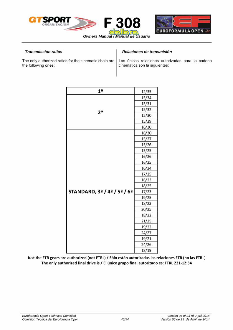
1ª 12/35
15/34
15/31
15/32
15/30
15/29
16/30
16/30
15/27
15/26
15/25
16/26
16/25
16/24
17/25
16/23
18/25
17/23
19/25
18/23
20/25
18/22
21/25
19/22
24/27
19/21
24/26
18/19
2ª
STANDARD, 3ª / 4ª / 5ª / 6ª
Just the FTR gears are authorized (not FTRL) / Sólo están autorizadas las relaciones FTR (no las FTRL)
The only authorized final drive is / El único grupo final autorizado es: FTRL 221‐12:34
Transmission ratios
The only authorized ratios for the kinematic chain are the following ones:
Relaciones de transmisión Las únicas relaciones autorizadas para la cadena cinemática son la siguientes:

F 308
Owners Manual / Manual de Usuario
Euroformula Open Technical Comision Comisión Técnica del Euroformula Open 47/54
Version 05 of 23 rd April 2014 Versión 05 de 23 de Abril de 2014
Brake calipers Brake calipers, front and rear, have
mounting position. The correct position is shown at the following drawing. Brake discs, when turning, should reach, first of all, the caliper piston of the smaller diameter.
Pinzas de freno. Las pinzas de freno, tanto las delanteras
como las traseras, tienen posición de montaje. Las posiciones correctas se muestran en los dibujos adjuntos. Los discos de freno al girar, han de alcanzar primero al pistón de menor diámetro de las pinzas.
For the Euroformula Open, the only authorized parts for the brake discs assembly are those delivered with the vehicle, that are the following:
Front left caliper : Brembo Ref. XA6S001
30/36
Front right caliper :Brembo Ref. XA6S002
30/36
Rear left caliper. Brembo Ref. XA6S003
30/36
Rear right caliper : Brembo Ref. XA6S004
30/36
Para el Euroformula Open, las únicas pinzas de freno autorizadas son las entregadas con el vehículo, a saber:
Pinza de freno delantera izq. Brembo Ref.
XA6S001 30/36
Pinza de freno delantera der. Brembo Ref.
XA6S002 30/36
Pinza de freno trasera Izq. Brembo Ref.
XA6S003 30/36
Pinza de freno trasera der. Brembo Ref.
XA6S004 30/36

F 308
Owners Manual / Manual de Usuario
Euroformula Open Technical Comision Comisión Técnica del Euroformula Open 48/54
Version 05 of 23 rd April 2014 Versión 05 de 23 de Abril de 2014
Brake pads
The only authorized brake pads for the F-312 are the FERODO FRP 3103C and FRP3103-PROTOF3, with the usual identification marks of the Championship. Attached the graph with the friction coefficient behavior of both references.
Pastilas de freno Las únicas pastillas autorizadas para el F-312 son las FERODO con referencias FRP 3103C-GT08F3, y FRP3103-PROTOF3, con las marcas identificativas del Campeonato. A continuación se adjunta el gráfico con el comportamiento frente a la fricción de ambas referencias.
F 308
Owners Manual / Manual de Usuario
Euroformula Open Technical Comision Comisión Técnica del Euroformula Open 49/54
Version 05 of 23 rd April 2014 Versión 05 de 23 de Abril de 2014
Brake master cilinders
Besides the original master cylinder (Girling – ¾ ‘’), the following ones are also autorized:
AP ref. CP2623-91PRT115 – 17,8 mm, 19,1 mm and 20,6 mm (with its reservoirs CP4709-12 -75 cc- and CP4709-11 -123 cc-)
Brembo ref. 109243.54 – 17,46 mm (with its reservoir 10.8687.10 -83 cc- )
Brembo ref. 109243.74 – 19,0 mm (with its reservoir 10.8687.10 -83 cc- )
Brembo ref. 109243.84 – 20,64 mm (with its reservoir 10.8687.10 -83 cc- )
When fitting any of the authorized master cylinders, the standard master cylinder support could be fitted with an spacer to properly install the steering sensor. This modification should be previously authorized by the F3 OpenTechnical Delegate.
Bombas de freno Además de la bomba de freno original (Brembo ref. XA6.S2.13 – 19mm), se autorizan las siguientes:
AP ref. CP2623-91PRT115 – 17,8 mm, 19,1 mm y 20,6 mm (con sus depósitos CP4709-12 -75 cc- y CP4709-11 -123 cc-)
Brembo ref. 109243.54 – 17,46 mm (con su depósito 10.8687.10 -83 cc- )
Brembo ref. 109243.74 – 19,0 mm ((con su depósito 10.8687.10 -83 cc- )
Brembo ref. 109243.84 – 20,64 mm ((con su depósito 10.8687.10 -83 cc- )
Cuando se monte alguna de las bombas anteriores, se podrá suplementar el soporte de las bombas originales, para el montaje del sensor de dirección. Esta modificación deberá estar previamente autorizada por el Delegado Técnico del F3 Open.
Brake discs
For the Euroformula Open, the only authorized parts for the brake discs assembly are those delivered with the vehicle, that are the following:
Right disc: BREMBO Ref. 09ª26111
Left disc: BREMBO Ref. 09ª26121
Brake disc bell: BREMBO Ref XA6S140
Fixation bolt: BREMBO Ref. XA5K051
Washer: BREMBO Ref. XA6S197
Discos de freno Para el Euroformula Open, las únicas piezas autorizadas para el conjunto de los discos de freno son las entregadas con el vehículo, a saber:
Disco de freno der:BREMBO Ref. 09ª26111
Disco de freno izq: BREMBO Ref. 09ª26121
Núcleo de disco de freno: BREMBO Ref
XA6S140
Tornillo de fijación: BREMBO Ref. XA5K051
Arandela: BREMBO Ref. XA6S197

F 308
Owners Manual / Manual de Usuario
Euroformula Open Technical Comision Comisión Técnica del Euroformula Open 50/54
Version 05 of 23 rd April 2014 Versión 05 de 23 de Abril de 2014
Clutch
The only clutches that are authorized for the Euroformula Open are the AP bi-disc, with the following parts references:
Clutch mechanism: CP6002: OH90SF Intermediate discs: CP4124-102 Pressure plate: CP4124-103 Clutch discs: CP341418FM3
Embrague Los únicos conjuntos de embrague autorizados en el Euroformula Open es el AP bidisco, con las siguientes referencias:
Mecanismo embrague: CP6002: OH90SF Discos intermedios: CP4124-102 Plato de presión: CP4124-103 Discos de embrague: CP341418FM3
or
Clutch mechanism: CP6002: EUOF3 Intermediate discs: CP4124-102 Pressure plate: CP4124-103 Clutch discs: CP341418FM3:EUOF3
o
Mecanismo de embrague: CP6002: EUOF3 Discos intermedios: CP4124-102 Plato de presión: CP4124-103 Discos de embrague: CP341418FM3:EUOF3
Rims
Keeping always the original dimensions, the rims of the following manufacturers (when supplied by GT Sport) are authorized:
OZ ATS
Llantas Siempre manteniendo las dimensiones originales, las llantas de los siguientes fabricantes (si han sido suministradas por GT Sport), están autorizadas:
OZ ATS
Battery
The lithium bateries Iron Phosphate Lithium base are authorized (Polymer Lithium Polímero – LIPO- are not authorized) The following model will be available at GT Sport:
Super B 15 P, Dimensions 120 x 80 x 200 mm and Weight 2,2 kg.
The following batteries are also authorized:
DEKA ref. DEKAETX 30 L DEKA ref. DEKAETX 16 L FIAAM ref. 61 F2 SM DIN 53030
In order to assure the correct fixation of the battery, it is allowed to adjust the original support, and to fit it with isolation material.
Batería Se autoriza el montaje de baterías de litio con base Iron Phosphate Lithium (no están autorizadas las Lithium Polímero – LIPO-) GT Sport tendrá disponible el siguiente modelo, y sus características: Super B 15 P, Medidas 120 x 80 x 200 mm y
Peso 2,2 kg. Se autorizan también las siguientes baterías:
DEKA ref. DEKAETX 30 L DEKA ref. DEKAETX 16 L FIAAM ref. 61 F2 SM DIN 53030
Para garantizar el montaje correcto y seguro de la batería, se autoriza a ajustar el soporte original, y a acolcharlo con material aislante

F 308
Owners Manual / Manual de Usuario
Euroformula Open Technical Comision Comisión Técnica del Euroformula Open 51/54
Version 05 of 23 rd April 2014 Versión 05 de 23 de Abril de 2014
Entertainment modifications
In order to allow the correct maintenance and entertainment of the vehicles, the following modifications are autorized:
Make a hole at the side pod to permit the passage of the end of the exhaust line.
To cut the engine cover at the side of the airbox. This modification can result in an slightly different position of the airbox pressure sensor between cars.
To install and additional ground point (it would have to be authorized by the Technical Delegate during the technical scrutineering).
To modify the wiring loom in such a way that the fuel pumps do not get automatically on when the main contact switch is connected.
For the F-308 vehicles, in order to be able to use all the available configurations for the rear wishbones mountings, it is authorized to cut the gearbox side panels (F308 02A 004 / 005) to avoid the interference between the wishbones and the panels.
It is authorized to dismount the rear wheel deflectors (right and left) with reference numbers F3082A006 and F3082A007.
It is authorized to use the driveshaft, manufactured by Dallara, with reference F30808i016, appart from the initially sold, of reference F30808i009.
To install a heat protection, between the exhaust manifold and the gearbox, formed by two sheets of a 1,5 to 2 mm thickness, with anti heat shield, with the shape and approximate measures (for F 308) that are shown below,
Modificaciones para la explotación Para el correcto mantenimiento y explotación en carrera de los vehículos, se permiten las siguientes modificaciones:
Recortar el pontón lateral para el paso de la salida de la linea de escape.
Recortar el capó motor en la zona del airbox. Esta modificación puede original que la posición del sensor de presión del airbox varíe ligeramente entre distintos coches.
Instalar un punto de masa adicional (será necesario que el montaje sea autorizado por el Delegado Técnico en las verificaciones previas.
Modificar la instalación eléctrica para que las bombas de gasolina no se accionen automáticamente al poner el contacto.
Para poder utilizar todas configuraciones disponibles de los soportes de los triángulos de suspensión traseros (F308 02A 004 / 005), y así prevenir posibles interferencias entre los triángulos y los paneles laterales de la caja de cambios.
Se autoriza la eliminacion de los deflectores de rueda traseros (derecho e izquierdo) de referencias F3082A006 F3082A007y.
Se autoriza a la utilización del semieje fabricado por Dallara de referencia F30808i016, además del utilizado y comercializado inicialmente, de referencia F30808i009.
Se autoriza incorporar en los monoplazas una protección anti calórica, entre el colector de escape y la caja de cambios, formada por dos chapas –de un grosor entre 1.5 a 2 mm con revestimiento anticalorico con la forma y medidas aproximadas (para F308) que figuran en los esquemas adjuntos.

F 308
Owners Manual / Manual de Usuario
Euroformula Open Technical Comision Comisión Técnica del Euroformula Open 52/54
Version 05 of 23 rd April 2014 Versión 05 de 23 de Abril de 2014

F 308
Owners Manual / Manual de Usuario
Euroformula Open Technical Comision Comisión Técnica del Euroformula Open 53/54
Version 05 of 23 rd April 2014 Versión 05 de 23 de Abril de 2014
It is authorized to use the throttle potentiometer, with reference 22A02017B, appart from the initially sold, with reference 22A02019A.
Se autoriza a la utilización del potenciómetro de mariposa de referencia 22A02017B , además del utilizado y comercializado inicialmente, de referencia 22A02019A .