Embed Size (px)
Citation preview
Inst
alla
tion
and
User
Man
ual
Mini DURAN 203CO Detection

3I-manmini-v02
INDEX DESCRIPTION OF THE SYSTEM .............................................................................................. 5
1 CONNECTION/DISCONNECTION ............................................................................................ 5 DURAN 203 PLUS detectors ..................................................................................................... 5 How the DURAN 203 PLUS detector operates ........................................................................ 5 Testing the detectors with gas ................................................................................................ 6
2 PUSH KEYPAD ......................................................................................................................... 6
3 LEDS ......................................................................................................................................... 7
4 ACOUSTICS................................................................................................................................ 7
5 DISPLAY MESSAGES ............................................................................................................... 8
6 PROGRAMMING ...................................................................................................................... 9 Ventilation level ....................................................................................................................... 9 Alarm level -evacuation- ......................................................................................................... 10 Alarms memory, Ventilation memory, Disconnection memory ................................................ 10 Detector calibration ................................................................................................................. 11 Line test .................................................................................................................................... 11
7 DETECTOR LED CODES ............................................................................................................ 12
8 TECHNICAL CHARACTERISTICS OF THE CONTROL UNIT ...................................................... 13
9 TECHNICAL CHARACTERISTICS OF THE DETECTOR .............................................................. 14
10 CONNECTION ........................................................................................................................... 15
11 QUICK PROGRAMMING .......................................................................................................... 16
12 RECOMMENDATIONS .............................................................................................................. 18
13 CERTIFICATIONS & HOMOLOGATIONS .................................................................................. 19
14 GUARANTEE ............................................................................................................................. 19

4© 2011 DURAN ELECTRONICA S.L.All rights reserved www.duranelectronica.com
5I-manmini-v02
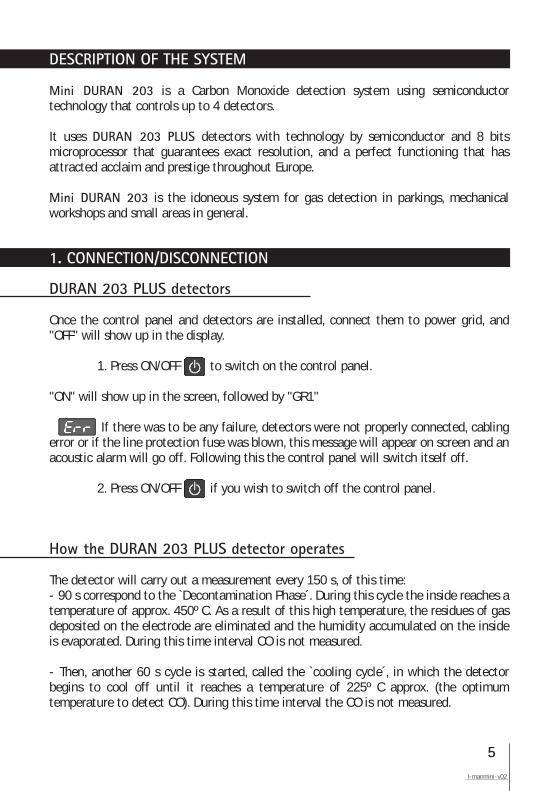
DESCRIPTION OF THE SYSTEM
Mini DURAN 203 is a Carbon Monoxide detection system using semiconductor technology that controls up to 4 detectors.
It uses DURAN 203 PLUS detectors with technology by semiconductor and 8 bits microprocessor that guarantees exact resolution, and a perfect functioning that has attracted acclaim and prestige throughout Europe.
Mini DURAN 203 is the idoneous system for gas detection in parkings, mechanical workshops and small areas in general.
1. CONNECTION/DISCONNECTION
DURAN 203 PLUS detectors
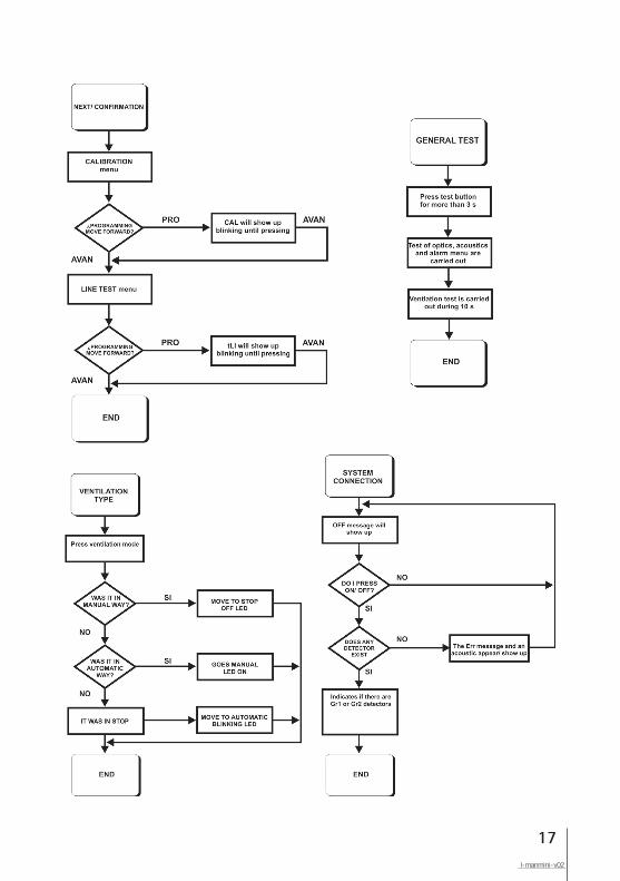
Once the control panel and detectors are installed, connect them to power grid, and "OFF" will show up in the display.
1. Press ON/OFF to switch on the control panel.
"ON" will show up in the screen, followed by "GR1"
If there was to be any failure, detectors were not properly connected, cabling error or if the line protection fuse was blown, this message will appear on screen and an acoustic alarm will go off. Following this the control panel will switch itself off.
2. Press ON/OFF if you wish to switch off the control panel.
How the DURAN 203 PLUS detector operates
The detector will carry out a measurement every 150 s, of this time:- 90 s correspond to the `Decontamination Phase´. During this cycle the inside reaches a temperature of approx. 450º C. As a result of this high temperature, the residues of gas deposited on the electrode are eliminated and the humidity accumulated on the inside is evaporated. During this time interval CO is not measured.
- Then, another 60 s cycle is started, called the `cooling cycle´, in which the detector begins to cool off until it reaches a temperature of 225º C approx. (the optimum temperature to detect CO). During this time interval the CO is not measured.
6© 2011 DURAN ELECTRONICA S.L.All rights reserved www.duranelectronica.com
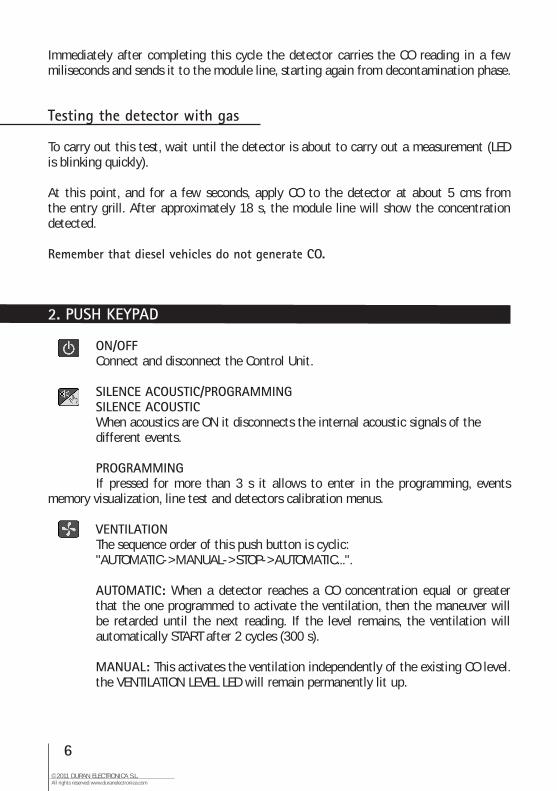
Immediately after completing this cycle the detector carries the CO reading in a few miliseconds and sends it to the module line, starting again from decontamination phase.
Testing the detector with gas
To carry out this test, wait until the detector is about to carry out a measurement (LED is blinking quickly).
At this point, and for a few seconds, apply CO to the detector at about 5 cms from the entry grill. After approximately 18 s, the module line will show the concentration detected.
Remember that diesel vehicles do not generate CO.
ON/OFF Connect and disconnect the Control Unit.
SILENCE ACOUSTIC/PROGRAMMING SILENCE ACOUSTIC When acoustics are ON it disconnects the internal acoustic signals of the different events.
PROGRAMMING If pressed for more than 3 s it allows to enter in the programming, events memory visualization, line test and detectors calibration menus.
VENTILATION The sequence order of this push button is cyclic: "AUTOMATIC->MANUAL->STOP->AUTOMATIC...".
AUTOMATIC: When a detector reaches a CO concentration equal or greater that the one programmed to activate the ventilation, then the maneuver will be retarded until the next reading. If the level remains, the ventilation will automatically START after 2 cycles (300 s).
MANUAL: This activates the ventilation independently of the existing CO level. the VENTILATION LEVEL LED will remain permanently lit up.
2. PUSH KEYPAD
7I-manmini-v02
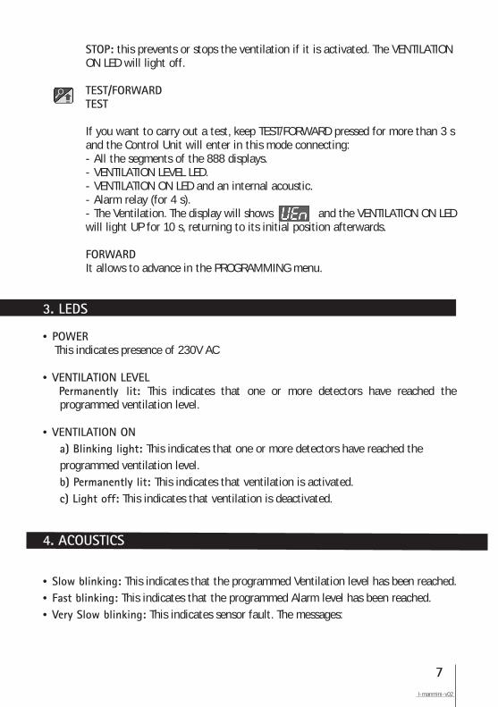
STOP: this prevents or stops the ventilation if it is activated. The VENTILATION ON LED will light off.
TEST/FORWARD TEST
If you want to carry out a test, keep TEST/FORWARD pressed for more than 3 s and the Control Unit will enter in this mode connecting: - All the segments of the 888 displays. - VENTILATION LEVEL LED. - VENTILATION ON LED and an internal acoustic. - Alarm relay (for 4 s). - The Ventilation. The display will shows and the VENTILATION ON LED will light UP for 10 s, returning to its initial position afterwards.
FORWARD It allows to advance in the PROGRAMMING menu.
• POWER This indicates presence of 230V AC
• VENTILATION LEVEL Permanently lit: This indicates that one or more detectors have reached the programmed ventilation level.
• VENTILATION ON a) Blinking light: This indicates that one or more detectors have reached the programmed ventilation level. b) Permanently lit: This indicates that ventilation is activated. c) Light off: This indicates that ventilation is deactivated.
• Slow blinking: This indicates that the programmed Ventilation level has been reached.• Fast blinking: This indicates that the programmed Alarm level has been reached.• Very Slow blinking: This indicates sensor fault. The messages:
3. LEDS
4. ACOUSTICS
8© 2011 DURAN ELECTRONICA S.L.All rights reserved www.duranelectronica.com
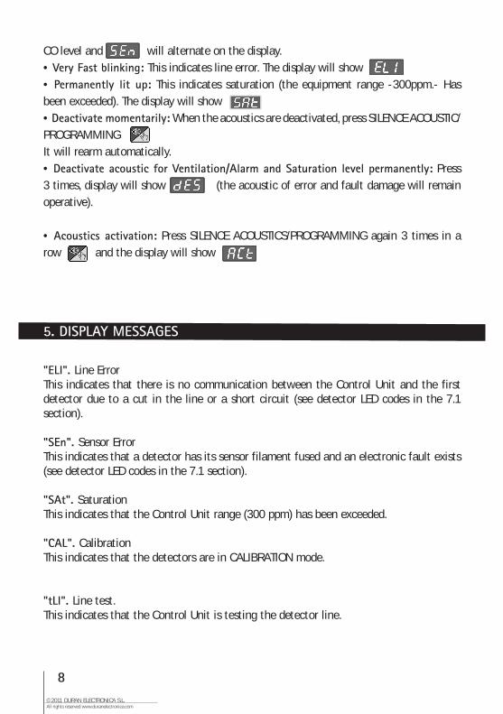
CO level and will alternate on the display.• Very Fast blinking: This indicates line error. The display will show• Permanently lit up: This indicates saturation (the equipment range -300ppm.- Has been exceeded). The display will show• Deactivate momentarily: When the acoustics are deactivated, press SILENCE ACOUSTIC/PROGRAMMINGIt will rearm automatically.• Deactivate acoustic for Ventilation/Alarm and Saturation level permanently: Press 3 times, display will show (the acoustic of error and fault damage will remain operative).
• Acoustics activation: Press SILENCE ACOUSTICS/PROGRAMMING again 3 times in a row and the display will show
"ELI". Line ErrorThis indicates that there is no communication between the Control Unit and the first detector due to a cut in the line or a short circuit (see detector LED codes in the 7.1 section).
"SEn". Sensor ErrorThis indicates that a detector has its sensor filament fused and an electronic fault exists (see detector LED codes in the 7.1 section).
"SAt". SaturationThis indicates that the Control Unit range (300 ppm) has been exceeded.
"CAL". CalibrationThis indicates that the detectors are in CALIBRATION mode.
"tLI". Line test.This indicates that the Control Unit is testing the detector line.
5. DISPLAY MESSAGES
9I-manmini-v02
"ALA". Alarm LevelThis indicates that the programmed Alarm Level has been reached, it alternates with the CO measure.
The sequence of the programming menus and events memory is as follows:
1º.- Ventilation Level 2º.- Alarm Level 3º.- Alarms Memory / 4º.- Ventilation Memory / 5º.- Disconnection Memory 6º.- Detector Calibration 7º.- Line Test
The programming sequences described next start from a normal functioning status (CO concentration reading), not from a previous one.
If your enter into programming mode and do not press any key in 15s, the menu will automatically START moving through the different options until it leaves this mode and returns to CO reading mode.
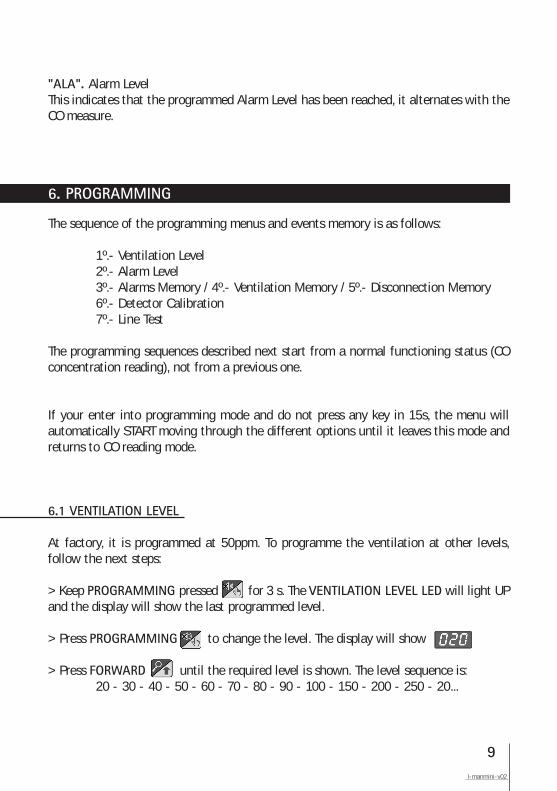
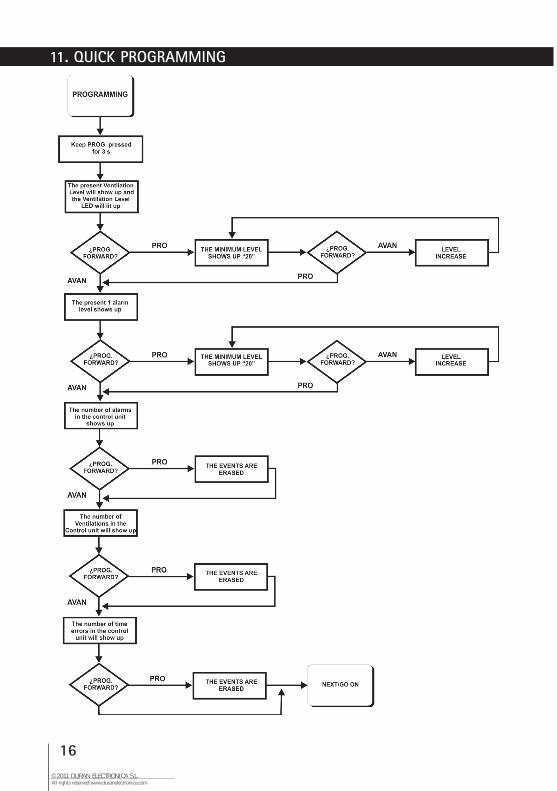
6.1 VENTILATION LEVEL
At factory, it is programmed at 50ppm. To programme the ventilation at other levels, follow the next steps:
> Keep PROGRAMMING pressed for 3 s. The VENTILATION LEVEL LED will light UP and the display will show the last programmed level.
> Press PROGRAMMING to change the level. The display will show
> Press FORWARD until the required level is shown. The level sequence is: 20 - 30 - 40 - 50 - 60 - 70 - 80 - 90 - 100 - 150 - 200 - 250 - 20...
6. PROGRAMMING
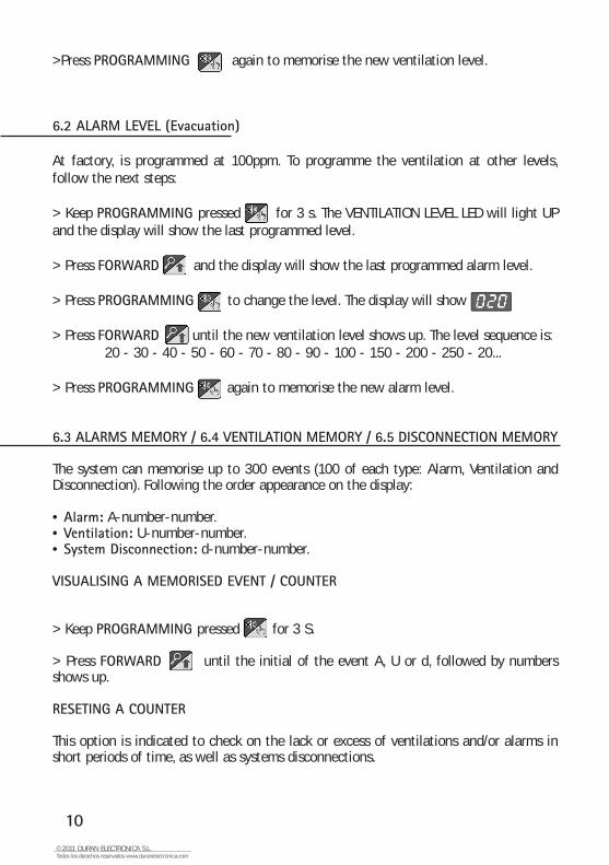
>Press PROGRAMMING again to memorise the new ventilation level.
6.2 ALARM LEVEL (Evacuation)
At factory, is programmed at 100ppm. To programme the ventilation at other levels, follow the next steps:
> Keep PROGRAMMING pressed for 3 s. The VENTILATION LEVEL LED will light UP and the display will show the last programmed level.
> Press FORWARD and the display will show the last programmed alarm level.
> Press PROGRAMMING to change the level. The display will show
> Press FORWARD until the new ventilation level shows up. The level sequence is: 20 - 30 - 40 - 50 - 60 - 70 - 80 - 90 - 100 - 150 - 200 - 250 - 20...
> Press PROGRAMMING again to memorise the new alarm level.
6.3 ALARMS MEMORY / 6.4 VENTILATION MEMORY / 6.5 DISCONNECTION MEMORY
The system can memorise up to 300 events (100 of each type: Alarm, Ventilation and Disconnection). Following the order appearance on the display:
• Alarm: A-number-number.• Ventilation: U-number-number.• System Disconnection: d-number-number.
VISUALISING A MEMORISED EVENT / COUNTER
> Keep PROGRAMMING pressed for 3 S.
> Press FORWARD until the initial of the event A, U or d, followed by numbers shows up.
RESETING A COUNTER
This option is indicated to check on the lack or excess of ventilations and/or alarms in short periods of time, as well as systems disconnections.
10© 2011 DURAN ELECTRONICA S.L.Todos los derechos reservados www.duranelectronica.com
11I-manmini-v02
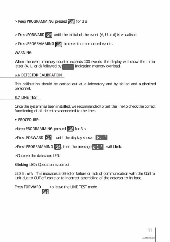
> Keep PROGRAMMING pressed for 3 s.
> Press FORWARD until the initial of the event (A, U or d) is visualised.
> Press PROGRAMMING to reset the memorised events.
WARNING
When the event memory counter exceeds 100 events, the display will show the initial letter (A, U, or d) followed by indicating memory overload.
6.6 DETECTOR CALIBRATION
This calibration should be carried out at a laboratory and by skilled and authorized personnel.
6.7 LINE TEST
Once the system has been installed, we recommended to test the line to check the correct functioning of all detectors connected to the lines.
• PROCEDURE:
>Keep PROGRAMMING pressed for 3 s.
>Press FORWARD until the display shows
>Press PROGRAMMING , then the message will blink.
>Observe the detectors LED:
Blinking LED: Operation is correct.
LED lit off: This indicates a detector failure or lack of communication with the Control Unit due to CUT off cable or to incorrect assembling of the detector to its base.
Press FORWARD to leave the LINE TEST mode.

12© 2011 DURAN ELECTRONICA S.L.All rights reserved www.duranelectronica.com
These are the LED codes for DURAN 203 PLUS detector:
• Green LED flashing every 10 s: Normal functioning.
• Red LED flashing for 15 s: It indicates the detector is about to measure.
• Red LED permanently lit up: It indicates the concentration of CO is 50ppm or higher.
• Red and green LEDs lit up simultaneously: Out of operation. The detector has not communicate with the Control Unit for more than 4 minutes. Check the cabling and make sure the detector is properly connected to its base.
.
7. LED CODES
13I-manmini-v02
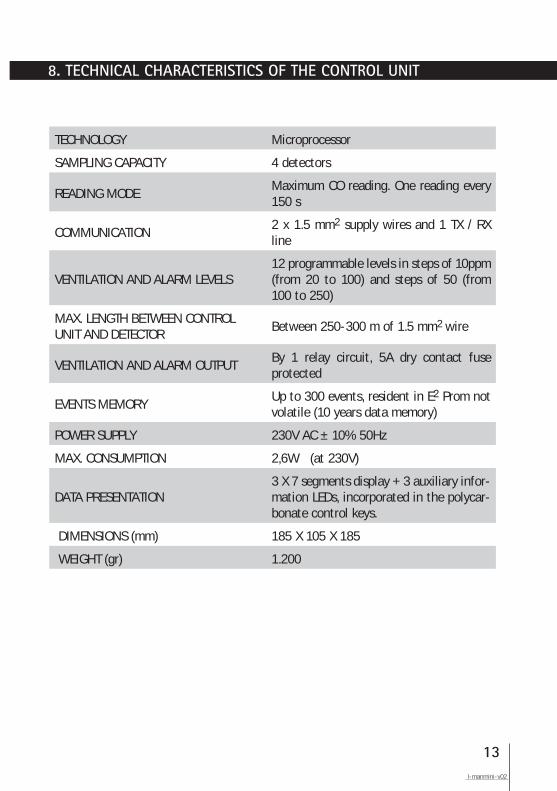
8. TECHNICAL CHARACTERISTICS OF THE CONTROL UNIT
TECHNOLOGY Microprocessor
SAMPLING CAPACITY 4 detectors
READING MODE Maximum CO reading. One reading every 150 s
COMMUNICATION2 x 1.5 mm2 supply wires and 1 TX / RX line
VENTILATION AND ALARM LEVELS12 programmable levels in steps of 10ppm (from 20 to 100) and steps of 50 (from 100 to 250)
MAX. LENGTH BETWEEN CONTROL UNIT AND DETECTOR
Between 250-300 m of 1.5 mm2 wire
VENTILATION AND ALARM OUTPUTBy 1 relay circuit, 5A dry contact fuse protected
EVENTS MEMORYUp to 300 events, resident in E2 Prom not volatile (10 years data memory)
POWER SUPPLY 230V AC ± 10% 50Hz
MAX. CONSUMPTION 2,6W (at 230V)
DATA PRESENTATION 3 X 7 segments display + 3 auxiliary infor-mation LEDs, incorporated in the polycar-bonate control keys.
DIMENSIONS (mm) 185 X 105 X 185
WEIGHT (gr) 1.200
14© 2011 DURAN ELECTRONICA S.L.All rights reserved www.duranelectronica.com
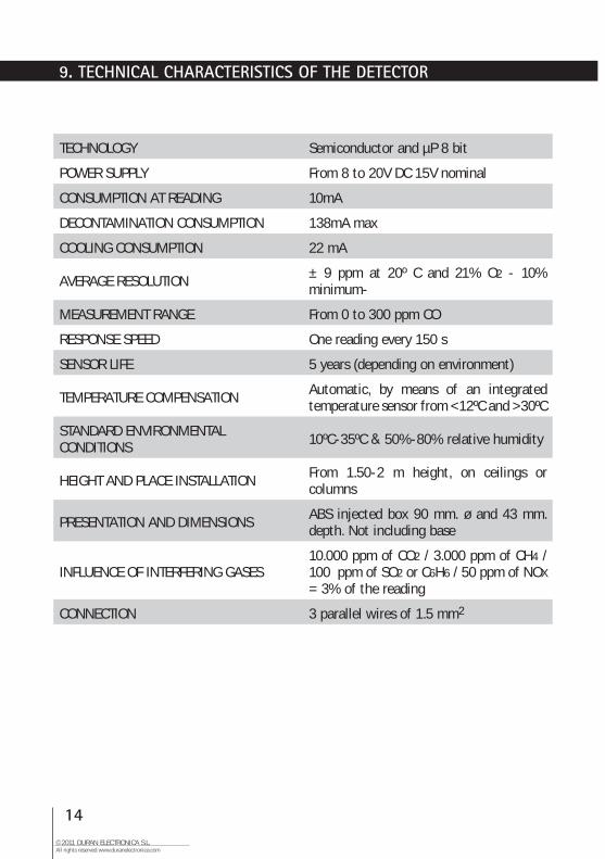
9. TECHNICAL CHARACTERISTICS OF THE DETECTOR
TECHNOLOGY Semiconductor and µP 8 bit
POWER SUPPLY From 8 to 20V DC 15V nominal
CONSUMPTION AT READING 10mA
DECONTAMINATION CONSUMPTION 138mA max
COOLING CONSUMPTION 22 mA
AVERAGE RESOLUTION ± 9 ppm at 20º C and 21% O2 - 10% minimum-
MEASUREMENT RANGE From 0 to 300 ppm CO
RESPONSE SPEED One reading every 150 s
SENSOR LIFE 5 years (depending on environment)
TEMPERATURE COMPENSATION Automatic, by means of an integrated temperature sensor from <12ºC and >30ºC
STANDARD ENVIRONMENTALCONDITIONS 10ºC-35ºC & 50%-80% relative humidity
HEIGHT AND PLACE INSTALLATION From 1.50-2 m height, on ceilings or columns
PRESENTATION AND DIMENSIONS ABS injected box 90 mm. ø and 43 mm. depth. Not including base
INFLUENCE OF INTERFERING GASES10.000 ppm of CO2 / 3.000 ppm of CH4 / 100 ppm of SO2 or C6H6 / 50 ppm of NOX = 3% of the reading
CONNECTION 3 parallel wires of 1.5 mm2
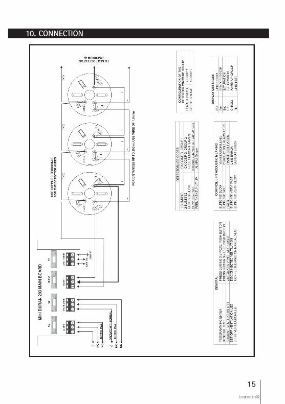
10. CONNECTION
15I-manmini-v02
16© 2011 DURAN ELECTRONICA S.L.All rights reserved www.duranelectronica.com
11. QUICK PROGRAMMING
17I-manmini-v02
18© 2011 DURAN ELECTRONICA S.L.All rights reserved www.duranelectronica.com
1.- Do not connect the detectors to their bases until the whole building work has been carried out and remember that once installed, power should be provided as soon as possible.
2.- To carry out the installation, use an individual duct and avoid installing the detector close to sources that generate electromagnetic disturbances (fluorescent lights, engines, counters, etc.) If you cannot avoid installing them close to these disturbances, we recommend you to use shielded cable (hose).
3.- Do not use the detector base as a register box to make service connections to more than one detector, use the terminals supplied for the cabling of the detector base.
4.- Do not drill holes in the Control Unit cabinet, as the metallic shavings could irreversibly damage the electronics.
5.- In compliance with the STANDARD EN 6.1010-1, 1.5 mm2 monopole cable should be used for the 230V AC connection to the Control Unit, protecting the input with a 5A contactor or circuit breaker and installing it as close as possible to the Control Unit.
6.- When designing the installation, try to avoid long stretches of cables to avoid voltage drops.
7.- Do not manipulate the module lines or the detectors without previously disconnecting the Control Unit.
8.- Remember that the minimum voltage needed for a detector to be able to function is 8V and check the voltage of the last detector on the line.
9.- The carbon-activated filter of the DURAN 203 PLUS detector should be replaced when it is 2.5 years old. The calibration of the detector, should be carried out in 5 years at our laboratory or at any other authorised by DURAN ELECTRONICA.
10.- REMEMBER that the detectors should not be left in the installation when:
• The Control Unit or the lines are disconnected. • There is no voltage or when there is only temporary power supply for the building work. • The building work has not been completely finished. • When maintenance work is being carried out, such as painting, changes to structure, when floors are being degreased, etc.When any of the above circumstances cannot be avoided: • Disconnect the Control Unit. • Remove the detectors, store them in their boxes and keep them in a clean and dry place.
12. RECOMMENDATIONS
19I-manmini-v02
13. CERTIFICATIONS & HOMOLOGATIONS
14. GUARANTEE
Mini DURAN 203 Control Unit holds the following Certifications and Homologations:
Certificate Nº 94604/01 from the OFFICIAL LABORATORY J.M. MADARIAGA.
Homologation CDM-0008 from the MINISTRY of INDUSTRY and ENERGY.
AENOR Certificate in accordance to EN 61010-1:93.
DURAN ELECTRONICA guarantees that Mini DURAN 203 Control Unit has been manufactured subject to strict quality controls.
Mini DURAN 203 is guaranteed against any manufacturing defect for 1 year from the date of purchase. If during this period of time any anomaly is detected, please advise your supplier or installer.
The guarantee covers the total repair of the equipment that DURAN ELECTRONICA technical services consider to be defective, so that the equipment can return to its normal use. This guarantee will only be valid if the equipment has been installed by a competent person and following the specifications in this manual. Negligent use or installation will exempt DURAN ELECTRONICA from its responsibilites for damage caused to property and/or people and from the fulfilment of the terms of this guarantee.
The guarantee does not cover:
Installations, periodical checks and maintenance.
Repairs caused by improper handling, inappropriate use, negligence, overload, insufficient power supply or neglecting the equipment, voltage shorts, defective installation and other external causes.
Repairs or adjustments carried out by personnel not authorised by DURAN ELECTRONICA.
Equipment transport costs.
DURAN ELECTRONICA reserves the right to carry out improvements or to include modifications to this equipment without prior notice.
C/ Tomás Bretón, 5028045 MADRID, EspañaTel.: +34 91 528 93 75Fax: +34 91 527 58 19
I-manmini-v02 Certificado nº FS 82426

![Detecting Carbon Monoxide Poisoning Detecting Carbon ...2].pdf · Detecting Carbon Monoxide Poisoning Detecting Carbon Monoxide Poisoning. Detecting Carbon Monoxide Poisoning C arbon](https://img.pdfslide.net/doc/110x75/5f551747b859172cd56bb119/detecting-carbon-monoxide-poisoning-detecting-carbon-2pdf-detecting-carbon.jpg)


![It's.easy. to. Play Duran. Duran[1]](https://img.pdfslide.net/doc/110x75/563dbb31550346aa9aab0788/itseasy-to-play-duran-duran1.jpg)

![Duran Duran - Decade [Pvg Book]](https://img.pdfslide.net/doc/110x75/577c7e881a28abe054a18ffb/duran-duran-decade-pvg-book.jpg)