Embed Size (px)
Citation preview

8/13/2019 Manual F9000N (RevB).pdf
http://slidepdf.com/reader/full/manual-f9000n-revbpdf 1/194
F9000N Series Operating Manual Rev. B- Dec. 10
- Page 1 -
© 2010 Fisnar Inc.
F9000N AND TMB200R/300R
SERIESROBOTS
OPERATING MANUAL

8/13/2019 Manual F9000N (RevB).pdf
http://slidepdf.com/reader/full/manual-f9000n-revbpdf 2/194
F9000N Series Operating Manual Rev. B- Dec. 10
- Page 2 -
© 2010 Fisnar Inc.
THIS PAGE INTENTIONALLY LEFT BLANK
8/13/2019 Manual F9000N (RevB).pdf
http://slidepdf.com/reader/full/manual-f9000n-revbpdf 3/194
F9000N Series Operating Manual Rev. B- Dec. 10
- Page 3 -
© 2010 Fisnar Inc.
TABLE OF CONTENTS
SECTION 1: SAFETY .............................................................................................................................. 7 1. CE CERTIFICATION R EQUIREMENTS ..................................................................................................... 8 2. SAFETY R ULES ...................................................................................................................................... 8 3. GENERAL CONDITIONS FOR SAFETY ..................................................................................................... 9 4. SAFETY DURING OPERATION ................................................................................................................ 9
SECTION 2: SYSTEM INSTALLATION ........................................................................................... 10 1. CONTROLLER ...................................................................................................................................... 11
1.1. Controller Specifications ........................................................................................................................................ 11 1.2. Controller Structure ............................................................................................................................................... 12 1.3. Front View .......... ........... .......... ........... .......... ........... .......... ........... .......... .......... ........... .......... .......... ........... ........... . 13 1.4. Rear View .................. ........... .......... ........... .......... ........... .......... ........... .......... .......... ........... .......... ........... .......... ..... 16 1.5. Connection Cable ................................................................................................................................................... 17 1.6. User I/O Cable ....................................................................................................................................................... 17 1.7. System I/O Cable .................................................................................................................................................... 17
2. I NSTALLATION OF THE PRODUCT ........................................................................................................ 18 2.1. Initial Considerations. .......... .......... ........... .......... ........... .......... .......... ........... .......... ........... .......... ........... .......... ..... 18 2.2. Connecting the Controller to the Manipulator ....................................................................................................... 19 2.3. Turning ON the Controller for the first time. ......................................................................................................... 21
SECTION 3: TEACHING OVERVIEW .............................................................................................. 22 1. TEACHING OVERVIEW ......................................................................................................................... 23 2. USING THE TEACH PENDANT .............................................................................................................. 25
2.1. Key Selection .......... .......... ........... .......... ........... .......... ........... .......... ........... .......... .......... ........... .......... ........... ........ 25 2.2. Key Assignments .......... ........... .......... .......... ........... .......... ........... .......... ........... .......... ........... .......... .......... ........... ... 26 2.3. Navigation Menu .................. .......... ........... .......... ........... .......... .......... ........... .......... ........... .......... ........... .......... ..... 27 2.4. Jogging .......... ........... .......... .......... ........... .......... ........... .......... ........... .......... ........... .......... ........... .......... ........... ...... 28 2.5. Data Entry .......... ........... .......... ........... .......... ........... .......... ........... .......... .......... ........... .......... .......... ........... ........... . 28 2.6. LED Panel .......... ........... .......... ........... .......... ........... .......... ........... .......... .......... ........... .......... .......... ........... ........... . 29
3. TEACH BOX K EY ASSIGNMENTS ......................................................................................................... 29 4. POINT TYPE FUNCTIONS SUMMARY .................................................................................................... 32
4.1. Point Menu ................ ........... .......... ........... .......... ........... .......... ........... .......... .......... ........... .......... ........... .......... ..... 32 4.2. Setup Menu ............................................................................................................................................................. 34 4.3. Condition Menu ...................................................................................................................................................... 36 4.4. Menu 1 ......... ........... .......... .......... ........... ........... .......... ........... .......... .......... ........... .......... ........... .......... ........... ........ 38 4.5. Menu 2 ......... ........... .......... .......... ........... ........... .......... ........... .......... .......... ........... .......... ........... .......... ........... ........ 39
SECTION 4: PROGRAMMING EXAMPLE ...................................................................................... 41 1. PROGRAMMING EXAMPLE ................................................................................................................... 42 2. EDITING A PROGRAM .......................................................................................................................... 47
2.1.
Changing a Point XYZ location .............................................................................................................................. 47
2.2. Insert / Delete an Instruction .......... ........... .......... ........... .......... ........... .......... .......... ........... .......... ........... .......... ..... 48 3. CHANGING THE PROGRAM NUMBER ................................................................................................... 48 4. CHANGING FROM TEACH MODE TO R UN MODE .................................................................................. 48 5. AUTO MODE AND STEP MODE IN R UN MODE .................................................................................. 49
SECTION 5: DISPENSING PARAMETERS ...................................................................................... 50 1. DISPENSE E ND SETUP ......................................................................................................................... 51

8/13/2019 Manual F9000N (RevB).pdf
http://slidepdf.com/reader/full/manual-f9000n-revbpdf 4/194
F9000N Series Operating Manual Rev. B- Dec. 10
- Page 4 -
© 2010 Fisnar Inc.
2. Z CLEARANCE ..................................................................................................................................... 52 3. LINE DISPENSE SETUP ......................................................................................................................... 53 4. R ETRACT............................................................................................................................................. 54 5. ADJUST ORIGIN ................................................................................................................................... 58 6. AUTO PURGE ...................................................................................................................................... 59
SECTION 6: POINT TYPE & FUNCTION REFERENCE ............................................................... 61 1. POINT MENU ....................................................................................................................................... 62
1.1. Dispense Dot ............. ........... .......... ........... .......... ........... .......... ........... .......... .......... ........... .......... ........... .......... ..... 62 1.2. Line Start ........... .......... ........... .......... .......... ........... .......... ........... .......... ........... .......... ........... .......... .......... ........... ... 62 1.3. Line Passing .................. .......... ........... .......... ........... .......... ........... .......... .......... ........... .......... .......... ........... ........... . 63 1.4. Arc Point........ ........... .......... .......... ........... .......... ........... .......... ........... .......... ........... .......... .......... ........... .......... ....... 63 1.5. Circle ...................................................................................................................................................................... 63 1.6. Center ..................................................................................................................................................................... 63 1.7. Line End ............ .......... .......... ........... .......... ........... .......... ........... .......... ........... .......... ........... .......... .......... ........... ... 65 1.8. Dummy......... ........... .......... .......... ........... ........... .......... ........... .......... .......... ........... .......... ........... .......... ........... ........ 66 1.9. End Program .......... .......... ........... .......... ........... .......... ........... .......... ........... .......... .......... ........... .......... ........... ........ 66 1.10. Dispense ON / OFF .......... ........... .......... ........... .......... ........... .......... .......... ........... .......... ........... .......... ........... ........ 66 1.11. Home Point ......... ........... .......... ........... .......... ........... .......... ........... .......... .......... ........... .......... .......... ........... ........... . 67 1.12. Wait Point ............................................................................................................................................................... 67 1.13. Stop Point ............................................................................................................................................................... 67 1.14. Brush Area .......... ........... .......... ........... .......... ........... .......... ........... .......... .......... ........... .......... .......... ........... ........... . 67 1.15. If .......... .......... ........... .......... ........... .......... .......... ........... .......... ........... .......... ........... .......... ........... .......... .......... ....... 70 1.16. Output ..................................................................................................................................................................... 70 1.17. Input ......... .......... ........... .......... ........... .......... ........... .......... ........... .......... .......... ........... .......... ........... .......... ........... . 70 1.18. Pulse ........... .......... ........... .......... .......... ........... .......... ........... .......... ........... .......... ........... .......... ........... .......... .......... 70 1.19. Point ................ .......... .......... ........... ........... .......... ........... .......... .......... ........... .......... ........... .......... ........... .......... ..... 70
2. CONDITION MENU............................................................................................................................... 71 2.1. Goto Address .......................................................................................................................................................... 71 2.2. Step & Repeat Y ...................................................................................................................................................... 71 2.3. Step & Repeat X...................................................................................................................................................... 76 2.4. Call Subroutine ....................................................................................................................................................... 76 2.5. Call Program .......................................................................................................................................................... 77 2.6. Loop Address .......... .......... ........... .......... ........... .......... ........... .......... ........... .......... .......... ........... .......... ........... ........ 78 2.7.
Label ........... .......... ........... .......... .......... ........... .......... ........... .......... ........... .......... ........... .......... ........... .......... .......... 78
2.8. Arm ........... .......... ........... .......... ........... .......... ........... .......... ........... .......... .......... ........... .......... ........... .......... ........... . 78 2.9. FixR .......... .......... ........... .......... ........... .......... ........... .......... ........... .......... .......... ........... .......... ........... .......... ........... . 79 2.10. Calculation ............................................................................................................................................................. 79 2.11. Jmov/Lmov .......... ........... .......... ........... .......... ........... .......... ........... .......... .......... ........... .......... .......... ........... ........... . 84 2.12. IncJ / IncL .......... .......... ........... .......... .......... ........... .......... ........... .......... ........... .......... ........... .......... .......... ........... ... 84 2.13. Offset ...................................................................................................................................................................... 84 2.14. PALLET ........... .......... ........... .......... ........... .......... ........... .......... ........... .......... .......... ........... .......... ........... .......... ..... 85 2.15. Pattern / Pattern End .......... ........... .......... .......... ........... .......... ........... .......... ........... .......... ........... .......... .......... ....... 88 2.16. Xmov ........... .......... ........... .......... .......... ........... .......... ........... .......... ........... .......... ........... .......... ........... .......... .......... 90
3. SETUP MENU....................................................................................................................................... 91 3.1. Line Speed ................ .......... .......... ........... .......... ........... .......... ........... .......... ........... .......... .......... ........... .......... ....... 91 3.2. Line Dispense Setup ........... ........... .......... .......... ........... .......... ........... .......... ........... .......... ........... .......... .......... ....... 91 3.3. Point Dispense Setup .......... ........... .......... .......... ........... .......... ........... .......... ........... .......... ........... .......... .......... ....... 91 3.4. Dispense End Setup .......... ........... .......... ........... .......... ........... .......... .......... ........... .......... ........... .......... ........... ........ 91 3.5. Z Clearance .......... ........... .......... .......... ........... .......... ........... .......... ........... .......... ........... .......... .......... ........... .......... 92 3.6. X/Y Move Speed ......... ........... .......... ........... .......... ........... .......... .......... ........... .......... ........... .......... ........... .......... ..... 92 3.7. Z Move Speed .............. ........... .......... .......... ........... .......... ........... .......... ........... .......... ........... .......... .......... ........... ... 92 3.8. Home Position .................. ........... .......... ........... .......... ........... .......... ........... .......... .......... ........... .......... ........... ........ 92 3.9. Retract ......... ........... .......... .......... ........... ........... .......... ........... .......... .......... ........... .......... ........... .......... ........... ........ 93 3.10. Auto Purge .......... ........... .......... ........... .......... ........... .......... ........... .......... .......... ........... .......... .......... ........... ........... . 93 3.11. Adjust Point # 1 ................ ........... .......... ........... .......... .......... ........... .......... ........... .......... ........... .......... ........... ........ 93 3.12. Adjust Point # 2 ................ ........... .......... ........... .......... .......... ........... .......... ........... .......... ........... .......... ........... ........ 93 3.13. Round .......... ........... .......... .......... ........... ........... .......... ........... .......... .......... ........... .......... ........... .......... ........... ........ 93 3.14. Z Lift .................. .......... .......... ........... .......... ........... .......... ........... .......... ........... .......... ........... .......... ........... .......... ... 95
8/13/2019 Manual F9000N (RevB).pdf
http://slidepdf.com/reader/full/manual-f9000n-revbpdf 5/194
F9000N Series Operating Manual Rev. B- Dec. 10
- Page 5 -
© 2010 Fisnar Inc.
4. MENU 1 ............................................................................................................................................... 96 4.1. Program Name ................. ........... .......... ........... .......... ........... .......... ........... .......... .......... ........... .......... ........... ........ 96 4.2. Z Axis Limit ....... .......... ........... .......... .......... ........... .......... ........... .......... ........... .......... ........... .......... .......... ........... ... 96 4.3. Initial Output ............... ........... .......... .......... ........... .......... ........... .......... ........... .......... ........... .......... .......... ........... ... 97 4.4. Cycle Counter ......................................................................................................................................................... 98 4.5. Set Password .......................................................................................................................................................... 98 4.6. Jog Speed ........... .......... ........... .......... .......... ........... .......... ........... .......... ........... .......... ........... .......... .......... ........... ... 99 4.7. Run Mode ........... ........... .......... ........... .......... ........... .......... ........... .......... .......... ........... .......... .......... ........... ........... . 99 4.8. Adjust Position ....... .......... ........... .......... ........... .......... ........... .......... ........... .......... .......... ........... .......... ........... ........ 99 4.9. Parameter .......... .......... ........... .......... .......... ........... .......... ........... .......... ........... .......... ........... .......... .......... ........... . 100 4.10. Auto Tool Setting .................... .......... .......... ........... .......... ........... .......... ........... .......... ........... .......... .......... ........... . 102 4.11. Resume........... ........... .......... .......... ........... .......... ........... .......... ........... .......... ........... .......... ........... .......... ........... .... 104 4.12. Origin Searching .................................................................................................................................................. 104 4.13. Hour Meter ......... ........... .......... ........... .......... ........... .......... ........... .......... .......... ........... .......... .......... ........... .......... 104 4.14. PLC File Edit .......... .......... ........... .......... ........... .......... ........... .......... ........... .......... .......... ........... .......... ........... ...... 105 4.15. I/O Monitor........................................................................................................................................................... 105 4.16. Set Variable .......................................................................................................................................................... 105 4.17. EMG Mode ................ ........... .......... ........... .......... ........... .......... ........... .......... .......... ........... .......... ........... .......... ... 105
5. MENU 2 ............................................................................................................................................. 106 5.1. Point Utility ............... ........... .......... ........... .......... ........... .......... ........... .......... .......... ........... .......... ........... .......... ... 106
5.1.1. MDI Mode .......... .......... ........... .......... ........... .......... ........... .......... ........... .......... .......... ........... .......... ........... ...... 106 5.1.2. Numerical Move.......... .......... ........... .......... .......... ........... .......... ........... .......... ........... .......... ........... .......... ........ 106 5.1.3. Save Temp Point .............................................................................................................................................. 106 5.1.4. Retrieve Temp Point ......... ........... .......... ........... .......... ........... .......... ........... .......... ........... .......... ........... .......... . 106
5.2. Group Utility ........................................................................................................................................................ 106 5.2.1. Group Edit ....................................................................................................................................................... 106 5.2.1.1. Copy ....................................................................................................................................................... 107 5.2.1.2. Delete ................... ........... .......... .......... ........... .......... ........... .......... ........... .......... ........... .......... .......... ..... 108 5.2.1.3. Move ........... .......... ........... .......... .......... ........... .......... ........... .......... ........... .......... ........... .......... .......... ..... 109 5.2.1.4. Line SP (Line Speed) .......... .......... ........... .......... ........... .......... ........... .......... ........... .......... .......... ........... ..110 5.2.1.5. Dispen.TM (Dispense Time) ......... ........... .......... ........... .......... ........... .......... ........... .......... .......... ........... .. 111 5.2.1.6. Offset .......................................................................................................................................................112
5.2.2. Expand Step & Repeat .......... .......... ........... .......... ........... .......... ........... .......... ........... .......... ........... .......... ........ 113 5.2.3. Relocate Data ................ ........... .......... .......... ........... .......... ........... .......... ........... .......... ........... .......... .......... ..... 114 5.2.4. Adjust Origin ............ .......... ........... .......... ........... .......... .......... ........... .......... ........... .......... ........... .......... .......... 115
5.3. Program Utility ......... ........... .......... ........... .......... ........... .......... .......... ........... .......... ........... .......... ........... .......... ... 117 5.3.1. Copy Program / Delete Program .......... .......... ........... .......... ........... .......... .......... ........... .......... ........... .......... ... 117 5.3.2. Auto Offset ................... ........... .......... ........... .......... ........... .......... ........... .......... .......... ........... .......... ........... ...... 117
5.4. Memory Utility...... ........... .......... .......... ........... .......... ........... .......... ........... .......... ........... .......... .......... ........... ........ 118 5.4.1. Delete Memory.......... .......... ........... .......... ........... .......... .......... ........... .......... ........... .......... ........... .......... .......... 118
SECTION 7: PLC.................................................................................................................................. 119 1. CREATION OF A PLC FILE ................................................................................................................. 120 2. R UNNING A PLC FILE ........................................................................................................................ 123 3. PLC PROGRAM EXAMPLES ............................................................................................................... 124
3.1. LD / LDNOT /OUT .......... .......... ........... .......... .......... ........... .......... ........... .......... ........... .......... ........... .......... ........ 124 3.2. AND / ANDNOT ............... ........... .......... ........... .......... .......... ........... .......... ........... .......... ........... .......... ........... ...... 125 3.3. OR / ORNOT ........................................................................................................................................................ 126 3.4. ANDBK .......... ........... .......... .......... ........... .......... ........... .......... ........... .......... ........... .......... ........... .......... ........... .... 127 3.5. ORBK ................................................................................................................................................................... 128 3.6. MC/MCR ......... .......... ........... .......... ........... .......... ........... .......... ........... .......... .......... ........... .......... ........... .......... ... 129 3.7. SET/RESET ........................................................................................................................................................... 130 3.8. PULS/PULSNOT ........... .......... ........... .......... ........... .......... .......... ........... .......... ........... .......... ........... .......... .......... 131 3.9. T (Timer)............................................................................................................................................................... 132 3.10. C (Counter)........................................................................................................................................................... 133 3.11. MOV / DMOV ........... .......... ........... .......... .......... ........... .......... ........... .......... ........... .......... ........... .......... .......... ..... 134 3.12. ADD / DADD .......... .......... ........... .......... ........... .......... ........... .......... ........... .......... .......... ........... .......... ........... ...... 135 3.13. SUB / DSUB ......................................................................................................................................................... 135 3.14. MUL/DMUL .................. .......... ........... .......... ........... .......... ........... .......... .......... ........... .......... .......... ........... .......... 136 3.15. DIV / DDIV ......... ........... .......... ........... .......... ........... .......... ........... .......... .......... ........... .......... .......... ........... .......... 136
4. SYSTEM CONTROL CONTACT ............................................................................................................ 137

8/13/2019 Manual F9000N (RevB).pdf
http://slidepdf.com/reader/full/manual-f9000n-revbpdf 6/194
F9000N Series Operating Manual Rev. B- Dec. 10
- Page 6 -
© 2010 Fisnar Inc.
4.1. System Control Input ............................................................................................................................................ 137 4.2. System Control Output ......................................................................................................................................... 138
SECTION 8: ERROR LIST ................................................................................................................. 139 1. ERROR LIST FOR HARDWARE ............................................................................................................ 140 2. ERROR LIST FOR PROGRAM .............................................................................................................. 148
2.1. Need LINE START ........... .......... ........... .......... .......... ........... .......... ........... .......... ........... .......... ........... .......... ........ 148 2.2. Need LINE END ................. ........... .......... .......... ........... .......... ........... .......... ........... .......... ........... .......... .......... ..... 148 2.3. Need Step & Repeat .......... ........... .......... ........... .......... ........... .......... .......... ........... .......... ........... .......... ........... ...... 148 2.4. PROGRAM END ERROR .......... .......... ........... .......... ........... .......... ........... .......... ........... .......... ........... .......... ........ 148 2.5. LABL Not Exist .......... ........... .......... ........... .......... ........... .......... ........... .......... .......... ........... .......... ........... .......... ... 148
SECTION 9: APPENDIX ..................................................................................................................... 149 1. APPENDIX A: USER I/O BOARD ........................................................................................................ 150 2. APPENDIX B: SYSTEM I/O BOARD .................................................................................................... 160 3. APPENDIX C: EQUIPMENT (MACHINE) CONNECTION ......................................................................... 168 4. APPENDIX D : MACHINE DIMENSIONS .............................................................................................. 179
4.1. F9300N .......... ........... .......... .......... ........... .......... ........... .......... ........... .......... ........... .......... ........... .......... ........... .... 179 4.2. F9304N .......... ........... .......... .......... ........... .......... ........... .......... ........... .......... ........... .......... ........... .......... ........... .... 180 4.3. F9600N .......... ........... .......... .......... ........... .......... ........... .......... ........... .......... ........... .......... ........... .......... ........... .... 181 4.4. F9604N .......... ........... .......... .......... ........... .......... ........... .......... ........... .......... ........... .......... ........... .......... ........... .... 182 4.5. F9800N .......... ........... .......... .......... ........... .......... ........... .......... ........... .......... ........... .......... ........... .......... ........... .... 183 4.6. F9804N .......... ........... .......... .......... ........... .......... ........... .......... ........... .......... ........... .......... ........... .......... ........... .... 184 4.7. TMB200R.............................................................................................................................................................. 185 4.8. TMB300R.............................................................................................................................................................. 186
5. APPENDIX E : TABLE DIMENSIONS .................................................................................................... 187 5.1. F9300N/F9304N .......... ........... .......... .......... ........... .......... ........... .......... ........... .......... ........... .......... .......... ........... . 187 5.2. F9600N/F9604N .......... ........... .......... .......... ........... .......... ........... .......... ........... .......... ........... .......... .......... ........... . 188 5.3. F9800N/F9804N .......... ........... .......... .......... ........... .......... ........... .......... ........... .......... ........... .......... .......... ........... . 189
6. APPENDIX F: COORDINATES (AXES) OF ROBOTS ................................................................................ 190 6.1. Manipulator of F9000N Series ........... .......... ........... .......... ........... .......... .......... ........... .......... .......... ........... .......... 190 6.2. Manipulator of TMB200R / TMB300R Series .......... ........... .......... ........... .......... ........... .......... ........... .......... ........ 191
6.2.1. Joint Coordinates......... ........... .......... ........... .......... ........... .......... .......... ........... .......... ........... .......... ........... ...... 191 6.2.2. Cartesian Coordinates ..................................................................................................................................... 192

8/13/2019 Manual F9000N (RevB).pdf
http://slidepdf.com/reader/full/manual-f9000n-revbpdf 7/194
F9000N Series Operating ManualSection 1 : Safety Rev. B- Dec. 10
- Page 7 -
© 2010 Fisnar Inc.
Section 1:Safety

8/13/2019 Manual F9000N (RevB).pdf
http://slidepdf.com/reader/full/manual-f9000n-revbpdf 8/194
F9000N Series Operating ManualSection 1 : Safety Rev. B- Dec. 10
- Page 8 -
© 2010 Fisnar Inc.
F9000N Gantry and SCARA TMB200R/300R robots use the same hardware controller,
programming software and teach pendant. Therefore, the instructions and programming
information are presented in this Operating Manual for both of them.
1. CE Certi f ication Requirements
1. In order to meet the safety requirements of the CE directives (applicable in the countries
of European Union) the robots must be placed in an enclosure which can be supplied by
the Fisnar Inc. distributors.
2. The enclosure must prevent the access to the moving parts except through the
enclosure door.
3. The enclosure door switch must be connected to the door switch connector on the robotI/O cable.
2. Safety Rules
1. In order to use a robot in safety conditions, the user should prepare the safety work
regulations under the careful consideration of line layout and side-line establishments
where the robot is installed, and the operator must keep strictly to the safety work
regulations to prevent accidents. Also, standard operation procedure about the robot
must be written-up for safety, and appropriate measures for safety operation must be
taken, such as safety training of the operators.
2. Teaching operation and maintenance procedure of the robot should be set according to
the standards of the Industrial Safety and Health Law and Industrial Safety Regulations.
3. The user should prepare the safety operation regulations of the overall system and abide
by them.
4. In order to secure the robot‟s safety, please observe the general provisions related to the
safety operation of an industrial robot.
5. Prepare a safety management system, such as appointing operators responsible for the
safe operation of robot or deciding on safety supervisors, and give them thorough safety
training.

8/13/2019 Manual F9000N (RevB).pdf
http://slidepdf.com/reader/full/manual-f9000n-revbpdf 9/194

8/13/2019 Manual F9000N (RevB).pdf
http://slidepdf.com/reader/full/manual-f9000n-revbpdf 10/194
F9000N Series Operating ManualSection 2 : System Installation Rev. B- Dec. 10
- Page 10 -
© 2010 Fisnar Inc.
Section 2:System Installation
8/13/2019 Manual F9000N (RevB).pdf
http://slidepdf.com/reader/full/manual-f9000n-revbpdf 11/194
F9000N Series Operating ManualSection 2 : System Installation Rev. B- Dec. 10
- Page 11 -
© 2010 Fisnar Inc.
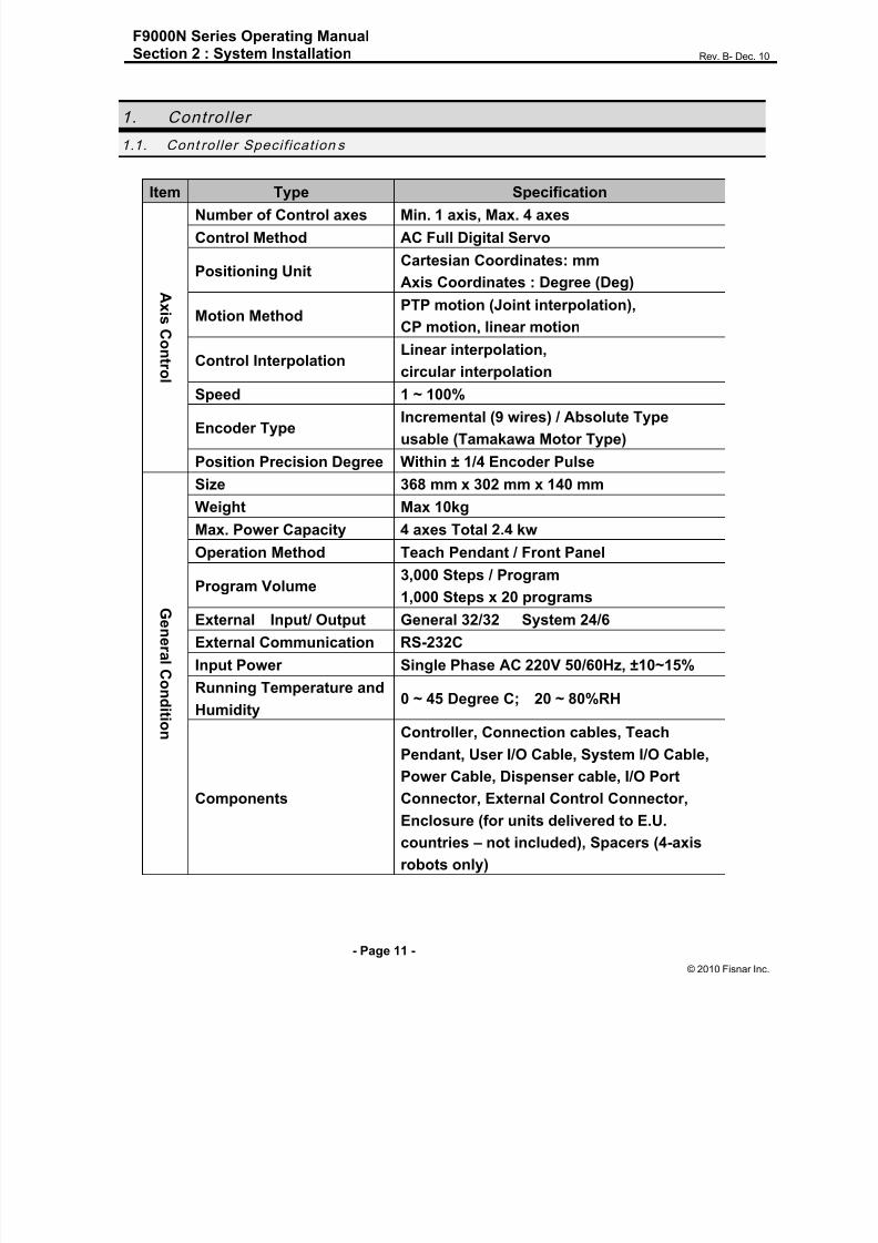
1. Control ler
1.1. Cont rol ler Specif icat ion s
Item Type Specification
AxisContro
l
Number of Control axes Min. 1 axis, Max. 4 axes
Control Method AC Full Digital Servo
Positioning UnitCartesian Coordinates: mm
Axis Coordinates : Degree (Deg)
Motion MethodPTP motion (Joint interpolation),
CP motion, linear motion
Control InterpolationLinear interpolation,
circular interpolation
Speed 1 ~ 100%
Encoder TypeIncremental (9 wires) / Absolute Type
usable (Tamakawa Motor Type)
Position Precision Degree Within ± 1/4 Encoder Pulse
GeneralCondition
Size 368 mm x 302 mm x 140 mm
Weight Max 10kg
Max. Power Capacity 4 axes Total 2.4 kw
Operation Method Teach Pendant / Front Panel
Program Volume 3,000 Steps / Program1,000 Steps x 20 programs
External Input/ Output General 32/32 System 24/6
External Communication RS-232C
Input Power Single Phase AC 220V 50/60Hz, ±10~15%
Running Temperature and
Humidity0 ~ 45 Degree C; 20 ~ 80%RH
Components
Controller, Connection cables, Teach
Pendant, User I/O Cable, System I/O Cable,
Power Cable, Dispenser cable, I/O PortConnector, External Control Connector,
Enclosure (for units delivered to E.U.
countries – not included), Spacers (4-axis
robots only)

8/13/2019 Manual F9000N (RevB).pdf
http://slidepdf.com/reader/full/manual-f9000n-revbpdf 12/194
F9000N Series Operating ManualSection 2 : System Installation Rev. B- Dec. 10
- Page 12 -
© 2010 Fisnar Inc.
Abnormality
Abnormalities
Over Current, Over Heat, Following Error,
Encoder error, Board malfunction,
Over Speed, Position deviation abnormality
Brake error, etc.
1.2. Cont rol ler Structu re
1. Controller
1. Controller : Consists of different types of boards and AMP, as shown
above.
2. Teach Pendant : Creates a work program and changes the configurations
of the system.
3. Connection Cable : Connects each channel of the controller and each axis of
the manipulator.
4. User I/O Cable : Connects the user I/O board and other equipment.5. System I/O Cable : Connects the system I/O board and other equipment.
According to the user‟s needs, the specifications of the Controller or the structure of the
machine can be changed.
The aspects and functions of each part of the Controller are as follows:
Main Board
Servo AMP
System I/O Board
User I/O Board
Servo Board
3. Connection
Cable
2. Teach Pendant
4. User I/O Cable
5. System I/O Cable
Machine
Power Supply Power Cable AC 220 V Power

8/13/2019 Manual F9000N (RevB).pdf
http://slidepdf.com/reader/full/manual-f9000n-revbpdf 13/194
F9000N Series Operating ManualSection 2 : System Installation Rev. B- Dec. 10
- Page 13 -
© 2010 Fisnar Inc.
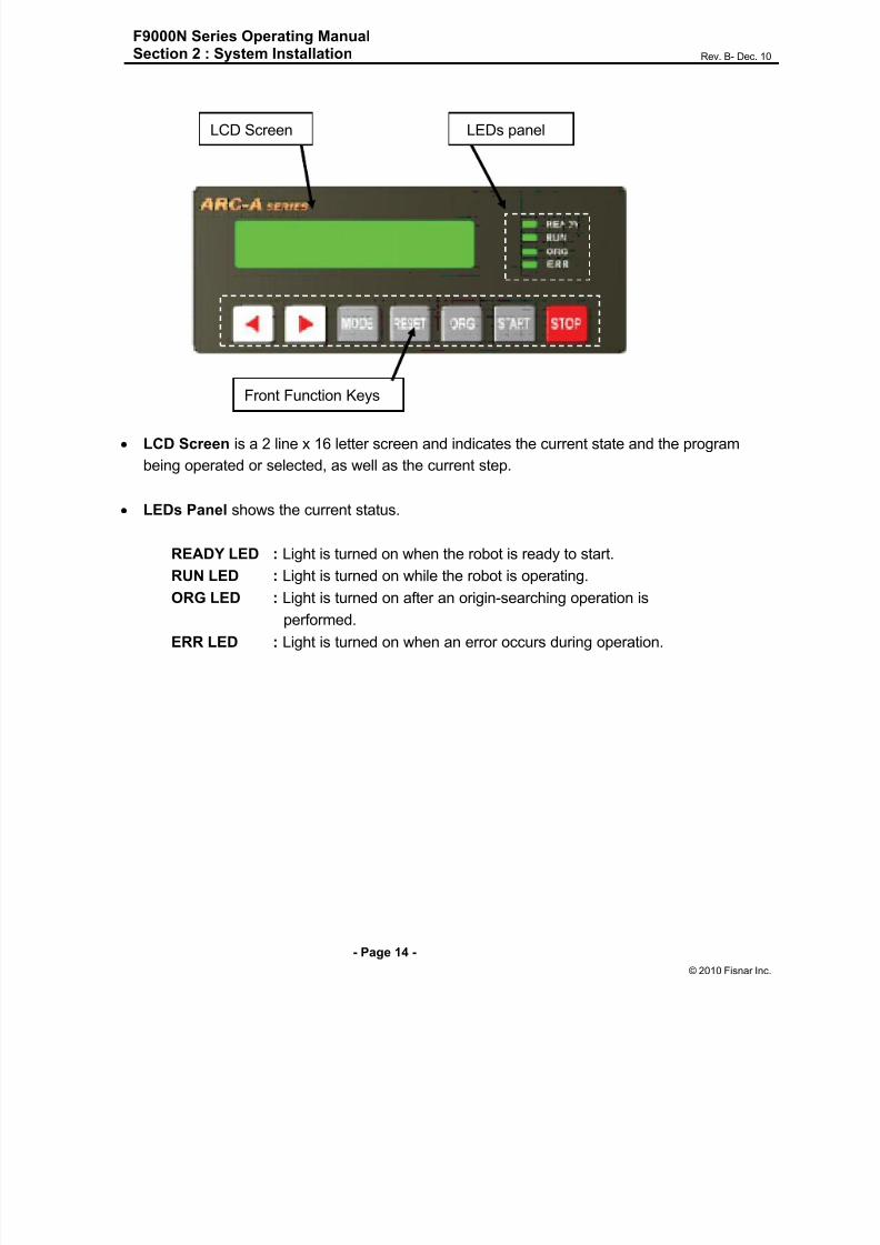
1.3. Front View
1. Ventilation openings: Allow the entrance of cold air into the unit to cool the inner heat
produced by the controller during operation. Do not block these openings.
2. Emergency Stop Button: Used when the controller is needed to be stopped
immediately.
3. Teach pendant (T-Box) port: Used to connect the Teach Pendant. Be careful not to
connect the HOST cable.
4. Host port (for RS-232C communication): Used for MMI Serial communication.
5. Power switch: Used to turn on or off the power of the controller. (The light comes on
when the power is ON.)6. Front Panel is used to operate the controller without a teach pendant.
1. Ventilation Openings
6. Front Panel
2. Emergency Button 3. Teach
Pendant Port
4. Host Port 5. Power
Switch
8/13/2019 Manual F9000N (RevB).pdf
http://slidepdf.com/reader/full/manual-f9000n-revbpdf 14/194

8/13/2019 Manual F9000N (RevB).pdf
http://slidepdf.com/reader/full/manual-f9000n-revbpdf 15/194
F9000N Series Operating ManualSection 2 : System Installation Rev. B- Dec. 10
- Page 15 -
© 2010 Fisnar Inc.
Front Panel keys are used to choose and operate program.
KEY Description
This key is used for selecting a Program. When selecting a Program,press this key to increase the program number by ten
This key is used for selecting a Program. When selecting a Program, press this key
to increase the program number one by one.
This key is used to change the controller to Teach Mode or Run Mode.
This key is used to reset the error caused.
This key is used to perform an origin-searching operation
(Go to position of the origin).
This key is used to start program running.
This key is used to stop program running.
◄
►
MODE
RESET
ORG
START
STOP

8/13/2019 Manual F9000N (RevB).pdf
http://slidepdf.com/reader/full/manual-f9000n-revbpdf 16/194
F9000N Series Operating ManualSection 2 : System Installation Rev. B- Dec. 10
- Page 16 -
© 2010 Fisnar Inc.
1.4. Rear View
1. Servo Board controls the Servo AMP.
2. Main Board regulates the System‟s control.
3. User I/O Board controls Input or Output and a user can use them freely. 32 contacts for
the input and 32 contacts for the output are available.4. SMPS supplies electric power to the controller.
5. System I/O Board is used only to control the system. 24 contacts for the system input
and 6 contacts for the system output are available.
6. AC Inlet is used to input the power, AC 220V.
7. Motor Power Connector is used to connect motors of the manipulator with connecting
cables, supplying high voltage to control the motor.
8. Encoder Connector is used to connect the encoder of the motor with the connecting
cables, allowing the current value of the encoder to be read.
9. Input Connector of User I/O board is used to connect with an external device. This is
only for input from the external device
10. Output Connector of User I/O board is used to connect with an external device. This
is only for the output to the external device.
11. System I/O Connector is used to connect with an external device or with the External
Control Connector. This is input or output for the system only.
2 4 1531
7 9 81086 11 7

8/13/2019 Manual F9000N (RevB).pdf
http://slidepdf.com/reader/full/manual-f9000n-revbpdf 17/194
F9000N Series Operating ManualSection 2 : System Installation Rev. B- Dec. 10
- Page 17 -
© 2010 Fisnar Inc.
1.5. Conn ection Cable
This cable is used to connect the machine and the channels of the controller.
This cable consists of two outlets - encoder connector and power connector – on the
controller side, while it has one outlet on the machine side.
For proper connection, please refer to Appendix C: Equipment (machine) Connection.
1.6. User I/O Cable
This cable is used to connect the user input/output of the external device and the
input/output port of the User I/O board. There are independent connectors for the user Input
and the user Output. Each connector has 32/32 contacts.
For more details, please refer to Appendix A.
1.7. Sys tem I/O Cable
This cable is used to connect the input/output ports of the external device and the
input/output ports of the system I/O board. The input and output are connected with only
one connector. The system input has 24 contacts and the output has 6 contacts.
For more details, please refer to Appendix B.
Power connector
Encoder connector
Manipulator connector
8/13/2019 Manual F9000N (RevB).pdf
http://slidepdf.com/reader/full/manual-f9000n-revbpdf 18/194
F9000N Series Operating ManualSection 2 : System Installation Rev. B- Dec. 10
- Page 18 -
© 2010 Fisnar Inc.
2. Instal lation of the Product
2.1. Ini t ial Cons ideration s.
1. Install the product in a well-ventilated area to avoid overheating.
2. Prevent vibration of the unit. Too much vibration can do considerable damage to the
controller.
3. Keep moisture level low. Avoid direct contact between water and the unit.
4. Protect unit against atmospheric agents.
5. Make all connected cables free from vibration.
6. Please install FG (Frame Ground).
7. Make sure that the motor specification indicated on the backside of the controller and
the one in the machine are matched.
8. Make sure that the power voltage is AC 220V.
9. Connect all cables appropriately and tie them up to prevent disconnection.
Note: To be seen Appendix F for the coordinates (axes) of the robots.
8/13/2019 Manual F9000N (RevB).pdf
http://slidepdf.com/reader/full/manual-f9000n-revbpdf 19/194
F9000N Series Operating ManualSection 2 : System Installation Rev. B- Dec. 10
- Page 19 -
© 2010 Fisnar Inc.
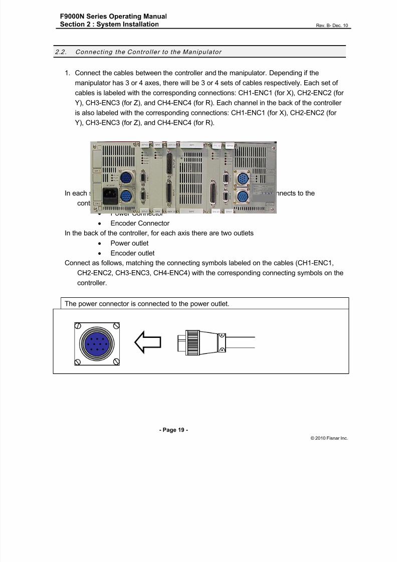
2.2. Connect ing the Control ler to the Manipulator
1. Connect the cables between the controller and the manipulator. Depending if the
manipulator has 3 or 4 axes, there will be 3 or 4 sets of cables respectively. Each set of
cables is labeled with the corresponding connections: CH1-ENC1 (for X), CH2-ENC2 (for
Y), CH3-ENC3 (for Z), and CH4-ENC4 (for R). Each channel in the back of the controller
is also labeled with the corresponding connections: CH1-ENC1 (for X), CH2-ENC2 (for
Y), CH3-ENC3 (for Z), and CH4-ENC4 (for R).
In each set of cables, the end that connects to the
controller has two connectors.
Power Connector
Encoder Connector
In the back of the controller, for each axis there are two outlets
Power outlet
Encoder outlet
Connect as follows, matching the connecting symbols labeled on the cables (CH1-ENC1,CH2-ENC2, CH3-ENC3, CH4-ENC4) with the corresponding connecting symbols on the
controller.
The power connector is connected to the power outlet.
X
Y
Z
R
8/13/2019 Manual F9000N (RevB).pdf
http://slidepdf.com/reader/full/manual-f9000n-revbpdf 20/194
F9000N Series Operating ManualSection 2 : System Installation Rev. B- Dec. 10
- Page 20 -
© 2010 Fisnar Inc.
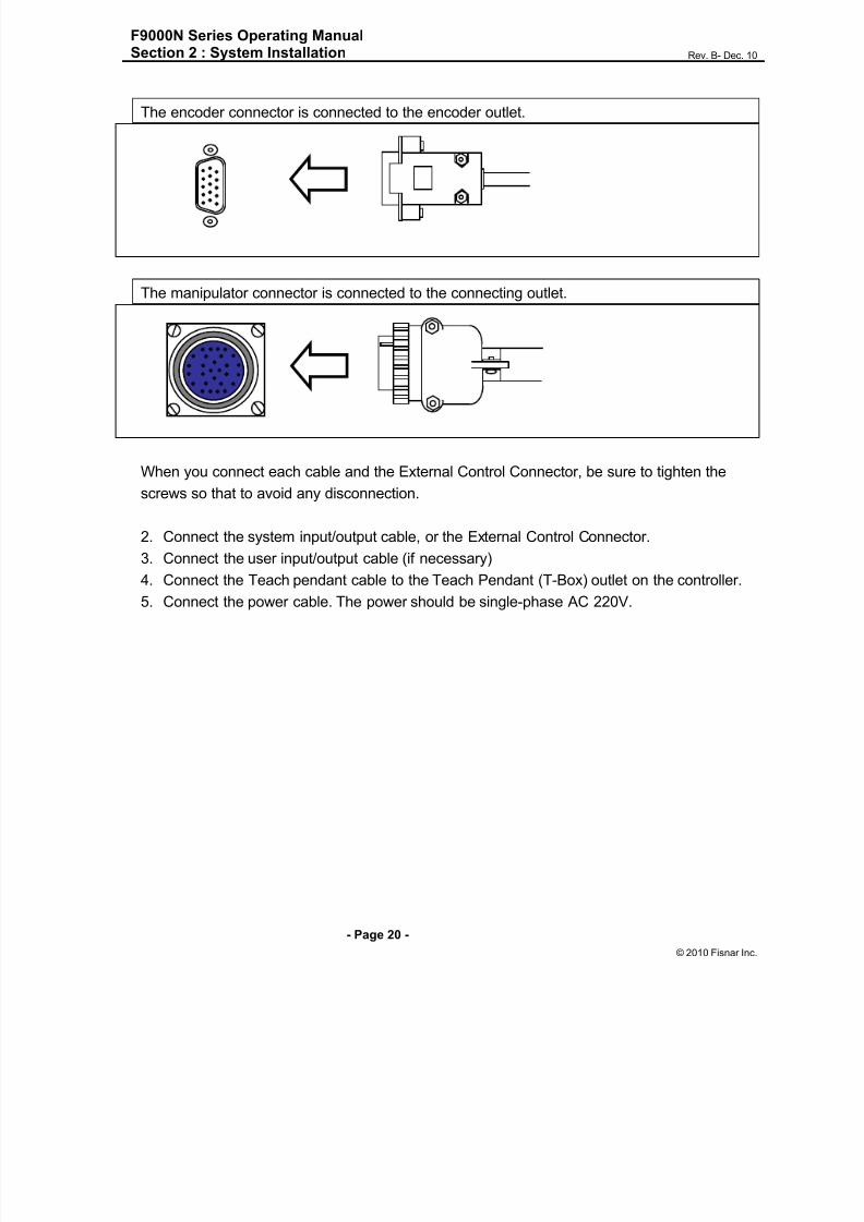
The encoder connector is connected to the encoder outlet.
The manipulator connector is connected to the connecting outlet.
When you connect each cable and the External Control Connector, be sure to tighten the
screws so that to avoid any disconnection.
2. Connect the system input/output cable, or the External Control Connector.
3. Connect the user input/output cable (if necessary)
4. Connect the Teach pendant cable to the Teach Pendant (T-Box) outlet on the controller.
5. Connect the power cable. The power should be single-phase AC 220V.

8/13/2019 Manual F9000N (RevB).pdf
http://slidepdf.com/reader/full/manual-f9000n-revbpdf 21/194
8/13/2019 Manual F9000N (RevB).pdf
http://slidepdf.com/reader/full/manual-f9000n-revbpdf 22/194
F9000N Series Operating ManualSection 3 : Teaching Overview Rev. B- Dec. 10
- Page 22 -
© 2010 Fisnar Inc.
Section 3:Teaching Overview

8/13/2019 Manual F9000N (RevB).pdf
http://slidepdf.com/reader/full/manual-f9000n-revbpdf 23/194
F9000N Series Operating ManualSection 3 : Teaching Overview Rev. B- Dec. 10
- Page 23 -
© 2010 Fisnar Inc.
1. Teaching Overview
A program consists of a series of instructions stored in the main unit memory. Each instruction
is stored in a numbered memory address. A memory address may record a point location, withan X, Y, Z and R (for 4-axis robots) value and point type or it may store an instruction which
sets a parameter, such as a dispensing time or a line speed.
When the program is run, the robot will step through each memory address in sequence and
execute the instruction found there. If the memory address contains a point location, the robot
will move the X, Y and Z axes to that location and also will execute the rotation corresponding
to the value of the R in that point. Depending on the type of point registered at that location, the
robot may also perform other functions, such as turn the dispenser on or off.
The most commonly used point types are: Dispense Dot, Line Start, Line Passing, Arc Point,
and Line End.To program the robot to dispense a „dot‟ of material, the dispensing tip must be jogged to the
desired XYZ location (and in the desired R position of the tip), then that location is registered as
a DISPENSE DOT type by pressing the appropriate key on the Teach Pendant.
To program the robot to dispense a
bead of material along a linear path, the XYZ location (and R position of the tip) of the start ofthe line is registered as a LINE START point. The locations where the tip changes direction
(and position) are registered as LINE PASSING points. The end of the line is registered as a
LINE END point:

8/13/2019 Manual F9000N (RevB).pdf
http://slidepdf.com/reader/full/manual-f9000n-revbpdf 24/194
F9000N Series Operating ManualSection 3 : Teaching Overview Rev. B- Dec. 10
- Page 24 -
© 2010 Fisnar Inc.
To dispense a bead of material in an arc, the XYZ location (and R position of the tip) of the start
of the line is registered as a LINE START point. The high point of the arc is registered as an
ARC Point. The end of the arc is registered as a LINE END point:
Lines and arcs can also be combined to dispense a bead of material along a complex path:
Once the required point locations for your program have been taught, the teach pendant is no
longer required. The unit can be switched to RUN mode and operated using the buttons and
switches on the main unit control panel.

8/13/2019 Manual F9000N (RevB).pdf
http://slidepdf.com/reader/full/manual-f9000n-revbpdf 25/194
F9000N Series Operating ManualSection 3 : Teaching Overview Rev. B- Dec. 10
- Page 25 -
© 2010 Fisnar Inc.
2. Using the Teach Pendant
The teach pendant enables the user to jog robot to input program data.
2.1. Key Selection
There are several functions assigned to most keys on the teach pendant. When such a key is
pressed alone, the function shown in the white colored area on the key is executed. The
functions MENU 1 , MENU 2 , Setup , and Condi t ion are all the default key functions that are
executed when their keys are pressed alone.
To access the function shown at the top of a blue key, press and release the Shift /Char key
first, then press the desired key. To select a function shown in the black area of a key, like – for
example - the Speed function, press and release Shift/Char , then press the Speed key.
When a number is required, the teach pendant will automatically switch to numeric entry mode.
The number represented by each key is shown in the lower left corner of the key.
When an Alphabetical character is required, press the Shift/Char key first. The character
represented by each key is shown in the lower side or in the lower right side of the key.
If Shift/Char is pressed,
released, and next the
Speed key is pressed,
Speed is executed.
When enteringalphabetical Characters,
if Shift/Char is pressed,
released, this key is „M‟.
When entering
numbers, this key is 7

8/13/2019 Manual F9000N (RevB).pdf
http://slidepdf.com/reader/full/manual-f9000n-revbpdf 26/194
F9000N Series Operating ManualSection 3 : Teaching Overview Rev. B- Dec. 10
- Page 26 -
© 2010 Fisnar Inc.
2.2. Key Ass ignm ents
Menu Keys
Opens the Point registration menu.
Opens the Setup menu.
Opens the Condition Menu.
Opens Menu # 1. It is also used for the Inch Jog Mode by
pressing the Shift /Char key first.
Opens Menu # 2. It is also used for the Mode Change by
pressing the Shift/Char key first.
Jog Keys
Jogs the X axis in the forward direction.
Jogs the X axis in the backward direction.
Jogs the Y axis in the left direction.
Jogs the Y axis in the right direction.
Jogs the Z axis UP.
Jogs the Z axis DOWN.
Jogs the Rotation axis.
F1
Setup
F2
Cond
ENT
Inch
Menu1
Mode
Menu2
- 1X
S
+ 1X
X
- 2Y
T
+ 2Y
Y
- 3Z
U
+ 3Z
Z
- 4W
V
+ 4W
W

8/13/2019 Manual F9000N (RevB).pdf
http://slidepdf.com/reader/full/manual-f9000n-revbpdf 27/194
F9000N Series Operating ManualSection 3 : Teaching Overview Rev. B- Dec. 10
- Page 27 -
© 2010 Fisnar Inc.
Changes jog speed. Right arrow button is used for increasing
jog speed. Left arrow button is used for decreasing jog speed.
Navigation Keys
Moves forward (1) memory address.
Moves backward (1) memory address.
Moves forward (10) memory addresses.
Moves backward (10) memory addresses.
2.3. Navigation Menu
Pressing any of the keys shown on the right will open the
corresponding menu.
Once the menu is open, use the up and down arrows to
move through the items on the menu.
Use the Page Up and Page Down keys to change to the
next page or previous page of the menu.
Press ENTER to select the current item.
►
SPD+
◄
SPD -
▼
+1
▲
-1
PgDn
+10
PgUp
-10
F1
Setup
F2
Cond
Inch
Menu1
Mode
Menu2ENT
▲
-1
▼
+1
PgDn
+10
SPD
PgUp
-10
SPD -
ENT

8/13/2019 Manual F9000N (RevB).pdf
http://slidepdf.com/reader/full/manual-f9000n-revbpdf 28/194
F9000N Series Operating ManualSection 3 : Teaching Overview Rev. B- Dec. 10
- Page 28 -
© 2010 Fisnar Inc.
2.4. Jogging
The tip is jogged by pressing the jog buttons after the
Servo button is pressed.
Jog speed has three velocity levels: low, middle and high.
If the right arrow button is pressed, the jog speed
changes to a faster level.
If the left arrow button is pressed, the jog speed changes
to a slower level.
The value of the jog speed (at the velocity level: high) can
be set using the function Jog Speed (Menu 1). (See
Section 6: 4.6 Jog Speed).
The Speed led display on the Teach Pendant shows the
velocity level: high, middle or low.
Changes to Inch Jog Mode. +
2.5. Data Entr y
The Teach Pendant is used also to enter numeric data. If a numeric value is required, the Teach
Pendant will automatically switch to numeric mode. Use the keys 0 – 9, (.), and (-) to enter the
values.
+ 1X
X
- 1X
S
+ 2Y
Y
- 2Y
T
+ 3Z
Z
- 3Z
U
+ 4W
W
- 4W
V
►
SPD +
◄
SPD -
Shift
/Char
Inch
Menu1
Servo
A

8/13/2019 Manual F9000N (RevB).pdf
http://slidepdf.com/reader/full/manual-f9000n-revbpdf 29/194
F9000N Series Operating ManualSection 3 : Teaching Overview Rev. B- Dec. 10
- Page 29 -
© 2010 Fisnar Inc.
2.6. LED Panel
This indicates the current system status and speed.
SERVO LED : The light is turned on when the robot is run or ready to move after
Servo is turned ON.
ORG LED : The light is turned on after the function of Origin is performed.
CHAR LED : The light is turned on when the CHAR key is pressed.
ERR LED : The light is turned on when the Error occurs in the robot.
INCH LED : The light is turned on when the current mode is Inch Mode.
LOW LED : The light is turned on when the current jog speed is low.
MED LED : The light is turned on when the current jog speed is medium.
HIGH LED : The light is turned on when the current jog speed is high.
3. Teach Box Key Assig nments
Key Funct ion
Opens Setup Menu.
Opens Condition Menu.
Opens Menu #1.
With Shift/Char key, it is used for Inch Jog Mode.
Opens Menu #2.
With Shift/Char key, it is used for Mode Change.
Turns the servo motor On/Off.
Releases or locks the Brake.
Jumps to a specified memory address.
F1
Setup
F2
Cond
Inch
Menu1
Mode
Menu2
Servo
A
Brake
B
Jump
C

8/13/2019 Manual F9000N (RevB).pdf
http://slidepdf.com/reader/full/manual-f9000n-revbpdf 30/194

8/13/2019 Manual F9000N (RevB).pdf
http://slidepdf.com/reader/full/manual-f9000n-revbpdf 31/194
F9000N Series Operating ManualSection 3 : Teaching Overview Rev. B- Dec. 10
- Page 31 -
© 2010 Fisnar Inc.
Key Funct ion
Confirms data entries. Also opens the Point registration
menu.
Shortcut for registering a Dispense Dot.
Shortcut for registering a Line Start point.
Shortcut for registering a Line Passing point.
Shortcut for registering a Line End point.
Shortcut for registering an Arc Point.
Shortcut for registering the End Program command.
Shortcut for registering Line Speed.
Shortcut for registering a Point Dispense Setup.
Shortcut for registering a Line Dispense Setup.
Changes the display to memory address number 0.
Changes the display to the last used memory address in
the program.
Changes to Run / Teach Mode.
„Home‟ the robot. Initializes all axes and moves to (0,0,0,0).
ENT
Shift
/Char
Dot
1 / G
Shift
/Char
Start
2 / H
Shift
/Char
Pass
3 / I
Shift
/Char
End
4 / J
Shift
/Char
Arc
5 / K
End Pr
6 / L
Shift
/Char
Speed
7 / M
Shift
/Char
Shift /Char
Setup8 / N
Shift
/Char 9 / O
Setup
First
0 / P
End
. / Q
Shift
/Char
Mode
Menu2
Home
- / R

8/13/2019 Manual F9000N (RevB).pdf
http://slidepdf.com/reader/full/manual-f9000n-revbpdf 32/194
8/13/2019 Manual F9000N (RevB).pdf
http://slidepdf.com/reader/full/manual-f9000n-revbpdf 33/194
F9000N Series Operating ManualSection 3 : Teaching Overview Rev. B- Dec. 10
- Page 33 -
© 2010 Fisnar Inc.
Funct ion Descript ion
Dispense ON / OFFRegisters an instruction which turns the dispenser on or off
at the current memory address.
Home Point Sets robot to home position.
Wait Point
Registers a Wait Point at the current X, Y, Z location (and R
position of tip). When executed, the tip will move to that
location and wait for the specified period of time.
Stop Point
Registers a Stop Point at the current X, Y, Z location (and R
position of tip). When executed, the tip will move to that
location and wait until the start button is pressed.
Brush Area Causes the tip to „paint‟ the defined area. The painted areacan be in the form of a rectangle or a circle / spiral.
IfRegisters an instruction that either sets the value of an
output signal or checks the status of an input signal.
OutputRegisters an instruction that sets the value of an output
signal.
Input Registers an instruction that waits for an input signal.
PulseRegisters an instruction that sets the value of an output
signal and Output Time.
PointSets point variable P0 ~ P99 by saving current position or
input numerical data.

8/13/2019 Manual F9000N (RevB).pdf
http://slidepdf.com/reader/full/manual-f9000n-revbpdf 34/194
F9000N Series Operating ManualSection 3 : Teaching Overview Rev. B- Dec. 10
- Page 34 -
© 2010 Fisnar Inc.
4.2. Setup Menu
Below is a list of functions that are found under the Setup key (Setup menu):
Funct ion Descript ion
Line Speed
Registers the LINE SPEED used for all lines from the
current memory address forward until another Line
Speed instruction is found.
Line Dis. Setup
Registers the LINE DISPENSE SETUP values which set
dispensing wait time at the start of lines („head‟ time)
waiting time at the end of lines („tail‟ time), and dispense
off length („head‟ length and „tail‟ length).Output
(„Output‟) The registered values will be used from the
current memory address forward until another Line
Dispense Setup instruction is found.
Point Dis. Setup
Registers POINT DISPENSE SETUP values which set
dispensing time and waiting time at the end of
dispensing („tail‟ time) for dots. Output („Output‟), The
registered values will be used from the current memory
address forward until another POINT DISPENSE
SETUP instruction is found.
Dispense End Setup
Registers the height and speed the tip should rise at the
end of dispensing. The registered values will be used
from the current memory address forward until another
DISPENSE END SETUP instruction is found.
Z Clearance
Registers the additional distance the tip should rise,
beyond the height set in Dispense End Setup, to allow
obstacles to be cleared as the tip moves from one figure
to another. Values will be used until another Z Clearance
instruction is found.
XY Move SpeedSets the movement speed of the X and Y axes when
moving from one figure to another in the program.
Z Move SpeedSets the movement speed of the Z axis when moving
from one figure to another in the program.

8/13/2019 Manual F9000N (RevB).pdf
http://slidepdf.com/reader/full/manual-f9000n-revbpdf 35/194
F9000N Series Operating ManualSection 3 : Teaching Overview Rev. B- Dec. 10
- Page 35 -
© 2010 Fisnar Inc.
Funct ion Descript ion
Home PositionChanges the position the robot moves to at the end of a
program cycle.
Retract
Registers Retract values at the current XYZ location.
Retract causes the tip to move up and back over the
dispensed bead after line dispensing.
Auto Purge
Registers Wait time and Purge time, for purging the
system at the end of a program.
Adjust Point #1
Saves current position and steps as a first data for
Relocate Data function. Saves current position to
temporary point #1.
Adjust Point #2
Saves current position and steps as a second data for
Relocate Data function. Saves current position to
temporary point #2.
CCD Shot Used for Vision Application
Relocate Used for Vision Application
Round Sets radius of a line at a Line Passing point.
Z Lift Select whether lifting Z axis or not, when robot MOVE topoint in TEACHING MODE.

8/13/2019 Manual F9000N (RevB).pdf
http://slidepdf.com/reader/full/manual-f9000n-revbpdf 36/194
F9000N Series Operating ManualSection 3 : Teaching Overview Rev. B- Dec. 10
- Page 36 -
© 2010 Fisnar Inc.
4.3. Cond it ion Menu
Below is a list of functions that are found under the key:
Function Description
Goto AddressCauses the program to jump to the specified memory
address when executed.
Step & Repeat X
Registers an instruction that will re-run a selected group of
memory addresses, stepping by a user-defined distance in
the X or Y axis after each copy. The matrix of parts is defined
by specifying the number of rows, the number of columns,
the X offset and the Y offset.
Step & Repeat X indicates that the robot will give priority to
the X axis, running the parts along the X axis first.
Step & Repeat Y
Registers an instruction that will re-run a selected group of
memory addresses, stepping by a user-defined distance in
the X or Y axis after each copy. The matrix of parts is defined
by specifying the number of rows, the number of columns,
the X offset and the Y offset.
Step & Repeat Y indicates that the robot will give priority to
the Y axis, running the parts along the Y axis first.
Call Subroutine
Causes the machine to jump to a specified memory address
and execute the instructions found there. When the end
program instruction is reached, program execution will
continue at address just after the call Subroutine instruction.
Call Program
Executes the specified program number from within the
current program. After the called program completes, the
current program will continue execution.
Loop AddressCauses the program to execute a group of memory
addresses a user-specified number of times.
F2
Cond

8/13/2019 Manual F9000N (RevB).pdf
http://slidepdf.com/reader/full/manual-f9000n-revbpdf 37/194
F9000N Series Operating ManualSection 3 : Teaching Overview Rev. B- Dec. 10
- Page 37 -
© 2010 Fisnar Inc.
Label Sets Label. Label can be used instead of Address Number.
Arm
For TMB Series, it determines the position of the arm.
For F9000N Series, it determines the XYZ coordinate or
RYZ coordinate.
FixRFixes/unfixes the axis rotation while a linear movement is
executed.
Calc Arithmetic Instruction.
Jmov/ LmovRegisters current XYZ position or Point variable to Moving
position.
IncJ / IncLRegisters current XYZ position or Point variable as an Offset
position.
XMovWhile moving, if a sensor signal is turned ON, robot will stop
immediately, and save current position to P98.
XCopy N/A
Pallet Registers a pallet movement setting.
OffsetSet Offset value or point number. Every position after Offset
command will be increased by Offset Value.
Pattern / End PatternIt is similar with the Step & Repeat Instruction, but it can
change the Repeat order.

8/13/2019 Manual F9000N (RevB).pdf
http://slidepdf.com/reader/full/manual-f9000n-revbpdf 38/194
F9000N Series Operating ManualSection 3 : Teaching Overview Rev. B- Dec. 10
- Page 38 -
© 2010 Fisnar Inc.
4.4. Menu 1
Below is a list of functions that are found under the Menu 1 key:
Funct ion Descript ion
Program Name Allows the user to register a name for the currentprogram number.
Z Axis LimitSets the limits between which the Z axis will move
during a program.
Initial OutputSets the status of the output signals when the machine
is initialized.
Cycle CounterEnables or disables the program cycle counter shown in
the display when in run mode.
Set PasswordSets Password to protect all programs from unwilling
editing.
Jog SpeedSets the value of the jogging speed, both the linear
speed and the rotation speed (for 4-axis robots).
Run Mode
Determines whether the robot operates in Standalone
mode (default) or Slave mode. Slave mode allows the
robot to be controlled by commands sent over the
RS232 port.
Adjust Position Sets Adjust Position for Adjust Origin.
Parameter Sets all parameters about machine and controller.
Resume
Determines if a program will restart from point #0 or the
point at which it was interrupted if a program is stopped
by an emergency stop or the enclosure door switch
open signal.
Origin searching Executes origin searching, making the robot to go to theposition established as home position.
Hour Meter Shows the working time and running time of the robot.
PLC File Edit Edits PLC File.
I/O Monitor Views Input/Output status.

8/13/2019 Manual F9000N (RevB).pdf
http://slidepdf.com/reader/full/manual-f9000n-revbpdf 39/194

8/13/2019 Manual F9000N (RevB).pdf
http://slidepdf.com/reader/full/manual-f9000n-revbpdf 40/194
F9000N Series Operating ManualSection 3 : Teaching Overview Rev. B- Dec. 10
- Page 40 -
© 2010 Fisnar Inc.
Funct ion Descript ion
Adjust Origin Adjusts origin position.
Program Utility
Copy Program Allows programs to be copied.
Delete Program Allows programs to be deleted.
Auto Offset Adjust position quickly.
Memory Utility
Delete Memory Clears whole memory.
Note: Certain functions shown on the display are not applicable to these units and consequently
they are marked in the manual as “N/A”.

8/13/2019 Manual F9000N (RevB).pdf
http://slidepdf.com/reader/full/manual-f9000n-revbpdf 41/194
F9000N Series Operating ManualSection 4 : Programming Example Rev. B- Dec. 10
- Page 41 -
© 2010 Fisnar Inc.
Section 4:Programming Example

8/13/2019 Manual F9000N (RevB).pdf
http://slidepdf.com/reader/full/manual-f9000n-revbpdf 42/194
F9000N Series Operating ManualSection 4 : Programming Example Rev. B- Dec. 10
- Page 42 -
© 2010 Fisnar Inc.
1. Programm ing Example
To help you become familiar with programming the robot, please follow the instructions below to
create a program that dispenses in the following pattern:
Notes:
We will create the pattern above in the program # 10.
We will use a line speed of 40 mm/sec for the lines and arcs in the program.
For dots, we will use a dispensing time of 0.50 seconds and a waiting (tail) time of 0.1
seconds after dispensing.

8/13/2019 Manual F9000N (RevB).pdf
http://slidepdf.com/reader/full/manual-f9000n-revbpdf 43/194
F9000N Series Operating ManualSection 4 : Programming Example Rev. B- Dec. 10
- Page 43 -
© 2010 Fisnar Inc.
Instru ct ion Display Show s
1 Turn on the controller.
PROG:00 AUTO
Press Move Key
Cycle Counter: 0
MODE PLC RESET EXIT
2 Select EXIT by pressing the Menu2 key.
-------------------
Press Home Key
To Find Origin
-------------------
3Press the Home button. The robot will move to the
home position.
ADDR:0 PROG:10
EMPTY
X:0 Y:0
Z:0 R:0
4
Press the F1/Setup key, then 1 to select Line
Speed (from page 1/4 of the Setup Menu) to
register a line speed of 40 mm/second at memory
address number 0.
Line Speed
----------------
Speed:
unit: mm/sec
5
The robot is now waiting for the speed to be
registered. Press 40, then ENTER to register a
speed of 40 mm / second.
ADDR:1 PROG:10
EMPTY

8/13/2019 Manual F9000N (RevB).pdf
http://slidepdf.com/reader/full/manual-f9000n-revbpdf 44/194
F9000N Series Operating ManualSection 4 : Programming Example Rev. B- Dec. 10
- Page 44 -
© 2010 Fisnar Inc.
Instru ct ion Display Show s
6
The display shows that we are at memory address
1 and that it is empty.
Jog the dispense tip to the first location in thediagram above (1: Line Start).
To jog the X, Y, Z axes and R position of tip, press
the respective Jog keys.
Press the key to jog fast. See
Teaching Overview Section 3:2.4 Jogging for
more information.
ADDR: 1 PROG: 10
X: 0 Y: 0
Z: 0 R: 0
7
Once the tip is at the correct X, Y, Z, R location for
the first point (1: Line Start ), press the ENTER
key, then 2 (from page 1/5 of the Point Menu) to
register the location as a Line Start point.
(Note: From now on, the symbols and the values
displayed for the X, Y, Z axes and R position willnot be written in the column “Display Shows” of
this example).
ADDR:2 PROG:10
EMPTY
8
The display will show that we are at memory
address 2 and it is empty. Jog the tip to the X, Y, Z,
R location of the second point (2: Line Passing ).
When the location is correct, press the ENT key,
then 3 (from page 1/5 of the Point Menu) to
register the location as a Line Passing point.
ADDR:3 PROG:10
EMPTY
9
Now jog the tip to the location of the third point
(3: Arc Poin t ). When the location is correct, press
the ENT key, then 1(from page 2/5 of the Point
Menu) to register the location as an Arc Point.
ADDR:4 PROG:10
EMPTY
►
SPD+
8/13/2019 Manual F9000N (RevB).pdf
http://slidepdf.com/reader/full/manual-f9000n-revbpdf 45/194
F9000N Series Operating ManualSection 4 : Programming Example Rev. B- Dec. 10
- Page 45 -
© 2010 Fisnar Inc.
Instru ct ion Display Show s
10
Jog the tip to the location of the fourth point
(4: Line Passing ). When the location is correct,
press the ENT key, then 3 (from page 1/5 of the
Point Menu) to register the location as a LinePassing point.
ADDR:5 PROG:10
EMPTY
11
Jog the tip to the location of the fifth point
(5: Line Passing ). When the location is correct,
press the ENT key, then 3 (from page 1/5 of the
Point Menu) to register the location as a Line
Passing point.
ADDR:6 PROG:10
EMPTY
12
Jog the tip to the location of the sixth point
(6: Line Passing ). When the location is correct,
press the ENT key, then 3 (from page 1/5 of thePoint Menu) to register the location as a Line
Passing point.
ADDR:7 PROG:10
EMPTY
13
Jog the tip to the location of the seventh point
(7: Line End ). When the location is correct, press
the ENT key, then 4 (from page 1/5 of the Point
Menu) to register the location as a Line End point.
ADDR:8 PROG:10
EMPTY
14
The line is now complete. The next step is to
register the dispense settings for the dots.
Press the F1/SETUP key, then 3 to register the
Point Dispensing Setup.
Point Disp Setup
Dis. Time: sec
Tail Time: secunit: sec
15
Type 0.5 to register a dispensing time of 0.5
seconds, and then press ENT.
Type 0.1 to register a waiting (tail) time after
dispensing of 0.1 seconds, then press ENT.
ADDR:9 PROG:10
EMPTY
16
Jog the tip to the location of the first dispense dot
(8: Dispense Dot ). When the location is correct,
press the ENT key, then 1(from page 1/5 of the
Point Menu) to register the location as a Dispense
Dot.
ADDR:10 PROG:10
EMPTY

8/13/2019 Manual F9000N (RevB).pdf
http://slidepdf.com/reader/full/manual-f9000n-revbpdf 46/194
F9000N Series Operating ManualSection 4 : Programming Example Rev. B- Dec. 10
- Page 46 -
© 2010 Fisnar Inc.
Instru ct ion Display Show s
17
Jog the tip to the location of the second dispense
dot (9: Dispense Dot ). When the location is
correct, press the ENT key, then 1 (from page 1/5
of the Point Menu) to register the location as aDispense Dot.
ADDR:11 PROG:10
EMPTY
18
Jog the tip to the location of the third dispense dot
(10: Dispen se Dot ). When the location is correct,
press the ENT key, then 1(from page 1/5 of the
Point Menu) to register the location as a Dispense
Dot.
ADDR:12 PROG:10
EMPTY
19
The program is now complete.
Press ENT, then 4 (from page 2/5 of the Point
Menu) to register address 12 as the END of theprogram.
ADDR:13 PROG:10
EMPTY
To run the program, press Shift/Char key, then Mode/Menu 2 key and then Move/D key.
8/13/2019 Manual F9000N (RevB).pdf
http://slidepdf.com/reader/full/manual-f9000n-revbpdf 47/194
F9000N Series Operating ManualSection 4 : Programming Example Rev. B- Dec. 10
- Page 47 -
© 2010 Fisnar Inc.
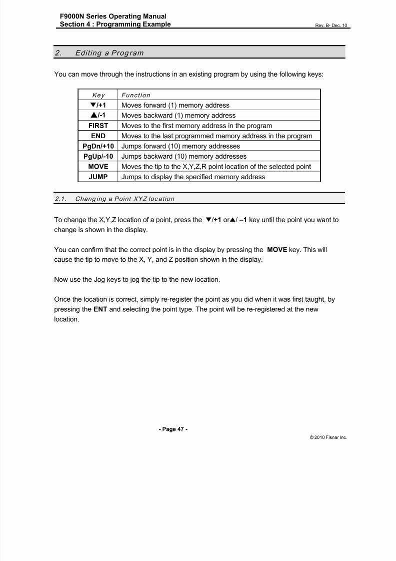
2. Edit ing a Prog ram
You can move through the instructions in an existing program by using the following keys:
Key Funct ion
/+1 Moves forward (1) memory address
/-1 Moves backward (1) memory address
FIRST Moves to the first memory address in the program
END Moves to the last programmed memory address in the program
PgDn/+10 Jumps forward (10) memory addresses
PgUp/-10 Jumps backward (10) memory addresses
MOVE Moves the tip to the X,Y,Z,R point location of the selected point
JUMP Jumps to display the specified memory address
2.1. Chang ing a Point XYZ loc ation
To change the X,Y,Z location of a point, press the ▼/+1 or ▲/ –1 key until the point you want to
change is shown in the display.
You can confirm that the correct point is in the display by pressing the MOVE key. This will
cause the tip to move to the X, Y, and Z position shown in the display.
Now use the Jog keys to jog the tip to the new location.
Once the location is correct, simply re-register the point as you did when it was first taught, by
pressing the ENT and selecting the point type. The point will be re-registered at the new
location.
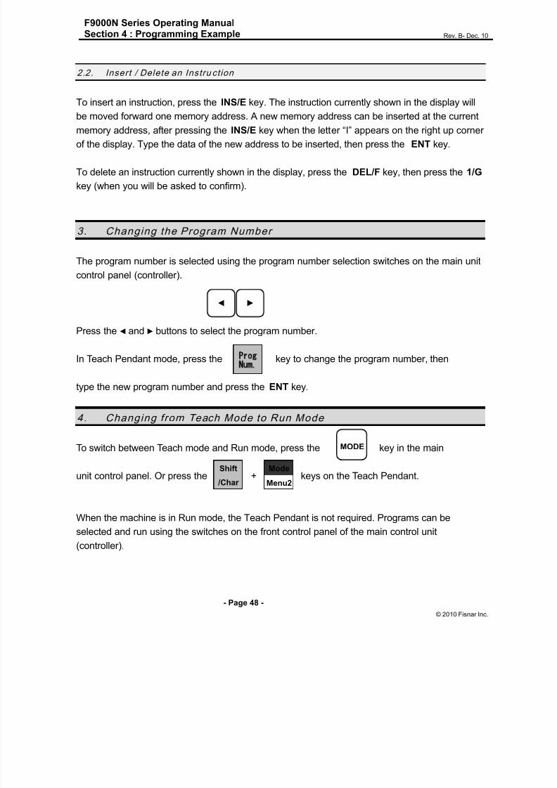
8/13/2019 Manual F9000N (RevB).pdf
http://slidepdf.com/reader/full/manual-f9000n-revbpdf 48/194
F9000N Series Operating ManualSection 4 : Programming Example Rev. B- Dec. 10
- Page 48 -
© 2010 Fisnar Inc.
2.2. Insert / Delete an Instru ction
To insert an instruction, press the INS/E key. The instruction currently shown in the display will
be moved forward one memory address. A new memory address can be inserted at the current
memory address, after pressing the INS/E key when the letter “I” appears on the right up corner
of the display. Type the data of the new address to be inserted, then press the ENT key.
To delete an instruction currently shown in the display, press the DEL/F key, then press the 1/G
key (when you will be asked to confirm).
3. Changing the Program Number
The program number is selected using the program number selection switches on the main unit
control panel (controller).
Press the ◄ and ► buttons to select the program number.
In Teach Pendant mode, press the key to change the program number, then
type the new program number and press the ENT key.
4. Changing from Teach Mode to Run Mode
To switch between Teach mode and Run mode, press the key in the main
unit control panel. Or press the + keys on the Teach Pendant.
When the machine is in Run mode, the Teach Pendant is not required. Programs can be
selected and run using the switches on the front control panel of the main control unit
(controller).
MODE
Prog
Num.
Mode
Menu2
Shift
/Char

8/13/2019 Manual F9000N (RevB).pdf
http://slidepdf.com/reader/full/manual-f9000n-revbpdf 49/194
F9000N Series Operating ManualSection 4 : Programming Example Rev. B- Dec. 10
- Page 49 -
© 2010 Fisnar Inc.
5. AUTO Mode and STEP Mode in Run Mode
In Run Mode have two modes that are Auto mode and Step Mode.
Auto Mode means that robot will run all program step automatically.
Step Mode means that robot will run each step by start Input one by one.
In Auto Mode, pressing start key will robot run program from start address to End address.

8/13/2019 Manual F9000N (RevB).pdf
http://slidepdf.com/reader/full/manual-f9000n-revbpdf 50/194
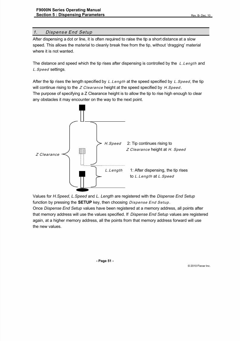
8/13/2019 Manual F9000N (RevB).pdf
http://slidepdf.com/reader/full/manual-f9000n-revbpdf 51/194

8/13/2019 Manual F9000N (RevB).pdf
http://slidepdf.com/reader/full/manual-f9000n-revbpdf 52/194
F9000N Series Operating ManualSection 5 : Dispensing Parameters Rev. B- Dec. 10
- Page 52 -
© 2010 Fisnar Inc.
2. Z Clearance
The purpose of the Z Clearance function is to cause the tip to rise high enough to clear all
obstacles as it moves from one point to another. If there are no obstacles between any of the
program points, a small Z Clearance value, such as 5 mm, can be used to minimize theprogram cycle time.
Values for the Z Clearance are registered by pressing the SETUP key, then choosing Z
Clearance. All the points from that memory address forward will use the Z Clearance value
until another Z Clearance value is found. Normally, a Z clearance instruction should be
registered in the beginning of a program, at one of the first few memory addresses.
The Z Clearance value may be specified as a relative value or as an absolute value. When
specified as a relative value, it is the distance to rise relative to the taught point location. Whenit is specified as an absolute value, it is the distance from the Z axis zero position which the tip
will rise to, regardless of the Z axis value of the taught point location. For example:
Z Clearance = 10 mm RELATIVE:
Z Clearance = 10 mm ABSOLUTE:
10 mm 10 mm
Z = 0 mm

8/13/2019 Manual F9000N (RevB).pdf
http://slidepdf.com/reader/full/manual-f9000n-revbpdf 53/194

8/13/2019 Manual F9000N (RevB).pdf
http://slidepdf.com/reader/full/manual-f9000n-revbpdf 54/194

8/13/2019 Manual F9000N (RevB).pdf
http://slidepdf.com/reader/full/manual-f9000n-revbpdf 55/194
F9000N Series Operating ManualSection 5 : Dispensing Parameters Rev. B- Dec. 10
- Page 55 -
© 2010 Fisnar Inc.
#1:RETRACT(NORMAL)
#1#2#3
#4
RETRACT
LENGTH
RETRACT HEIGHT
#2:RETRACT(SQUARE)
RETRACT HEIGHT
RETRACT
LENGTH
#2
#3
#1
#3:RETRACT(FORWARD)
RETRACT HEIGHT
#3
#2#1
RETRACT
LENGTH
#4:RETRACT(FORWARD SQUARE)
RETRACT
LENGTH
#1RETRACT HEIGHT#2
#3 #4

8/13/2019 Manual F9000N (RevB).pdf
http://slidepdf.com/reader/full/manual-f9000n-revbpdf 56/194
F9000N Series Operating ManualSection 5 : Dispensing Parameters Rev. B- Dec. 10
- Page 56 -
© 2010 Fisnar Inc.
Over Ang. Function only used for the center function. Please see section 6.1.6 more detailed
information
Over Angle 45deg
If you want to Z lift 2 mm
Diameter: 6mm
I wrote the over angle 45 degree so when the robot finish the circle, it lifts the Z-axis androtates the tip 45 degree on the circle without dispensing so it is not going to be more material
end of the circle
After insert all column, press ENTER, then two addresses are saved.
Retract type: OverAngle Z Lift: 2mm
Center X: 100 Y: 100 Z: 100 Diameter: 6
If Over Angle value is zero, Retract step will not be saved.
End of the circle lift
the Z axis and
rotates the tip about
#5:RETRACT(Over An g.)

8/13/2019 Manual F9000N (RevB).pdf
http://slidepdf.com/reader/full/manual-f9000n-revbpdf 57/194

8/13/2019 Manual F9000N (RevB).pdf
http://slidepdf.com/reader/full/manual-f9000n-revbpdf 58/194

8/13/2019 Manual F9000N (RevB).pdf
http://slidepdf.com/reader/full/manual-f9000n-revbpdf 59/194
F9000N Series Operating ManualSection 5 : Dispensing Parameters Rev. B- Dec. 10
- Page 59 -
© 2010 Fisnar Inc.
Instruct ion Display Show s
3
Press any key. The tip will move to the reference
point that was recorded in the Adjust Position.
If the new tip location is slightly different from thelast tip location, you should see that the tip is not
exactly at the reference point.
Adjust the First
Point
X: 10 Y: 20
Z: 30 R: 40
4
Jog the tip to the correct location for the
reference point.
When the location is correct, press ENT.
The program origin will be adjusted for the new
tip location.
Program Data
Adjusted !!!
6. Au to Purge
After the end of a program, the tip will go to the home position and material will be purged in a
continuous loop according to the parameters registered in the Auto Purge Setup command.
This command is very useful for two part materials that have a very short pot life.
For example, if a Wait Time of 5s and a Purge Time of 2s is registered in the Auto Purge Setup,
the following chart shows the Purge pattern.
Time s
Dis enser OFF
Dis enser ON
Wait
Purge
2 75 1210 15

8/13/2019 Manual F9000N (RevB).pdf
http://slidepdf.com/reader/full/manual-f9000n-revbpdf 60/194
8/13/2019 Manual F9000N (RevB).pdf
http://slidepdf.com/reader/full/manual-f9000n-revbpdf 61/194
F9000N Series Operating ManualSection 6 : Point Type & Function Reference Rev. B- Dec. 10
- Page 61 -
© 2010 Fisna
Section 6:Point Type & Function
Reference

8/13/2019 Manual F9000N (RevB).pdf
http://slidepdf.com/reader/full/manual-f9000n-revbpdf 62/194
F9000N Series Operating ManualSection 6 : Point Type & Function Reference Rev. B- Dec. 10
- Page 62 -
© 2010 Fisna
1. Point Menu
Below is a list of functions which are found under the ENTER key. These functions are
„point-type‟ functions. The values applied will occupy one memory address.
1.1. Dispen se Dot
Registers the current XYZR location as a Dispense point for dispensing a dot.
The dispense time and wait time must be set in a previous memory address by registering
a Point Dispense Setup instruction with the SETUP key.
The upward motion of the tip after dispensing can be controlled by registering a Dispense
End Setup instruction and / or a Z Clearance instruction in a previous memory address.
Dispense End Setup and Z Clearance instructions are registered using the SETUP key.
See also Section 6:3.3 Point Dispense Setup , Section 6:3.4 Dispense End Setup and
Section 6:3.5 Z Clearanc e .
1.2. Lin e Start
Registers the current XYZR location as a Line Start point for dispensing a line.
The line speed must be set in a previous memory address by registering a Speed
instruction using the SETUP key.
Dispense delay times used at Line Start point can be controlled by registering a Line Dis.
Setup instruction in a previous memory address. The Lin e Dis. Setup instruction is
registered by pressing the SETUP key.
See also Section 6:3.1 Lin e Speed and Section 6:3.2 Line Dispense Setup .

8/13/2019 Manual F9000N (RevB).pdf
http://slidepdf.com/reader/full/manual-f9000n-revbpdf 63/194
F9000N Series Operating ManualSection 6 : Point Type & Function Reference Rev. B- Dec. 10
- Page 63 -
© 2010 Fisna
1.3. Lin e Passing
Registers the current XYZR location as a Line Passing point, this being a location on the
line where the tip changes direction, such as at the corner of a rectangle.
1.4. Arc Point
Registers the current XYZR location as an Arc point, this being used to dispense material
along an arc or a circular path.
See Section 4: Programm ing Example , for an example of the use of an Arc Point.
1.5. Circle
Registers the current XYZR location as a Circle point in order to dispense material along a
circular path. For doing that it is necessary to enter three points on the circle to be
dispensed and to register them as: Line Start point (the first point), Circle point (the second
point) and Line End point (the third point).
1.6. Center
Centers function registers the current XYZR location as a Center point of circle in order to
dispense material along a circular path. For doing that it is necessary to enter diameter,
over angle and lift Z. Value.
Over Angle means that after dispensing the circle, while going through an extra part of the
circle defined by the Over Angle, the dispenser will be turned OFF
If you want to lift the Z at the end of the dispense, input Z lift value bigger than zero.
Center
Diameter: 6 mm {Type the diameter of the circle}
Over Angle: 45 degree {Type the angle between the 1 to 360}
Z lift: 2 mm {If you want to lift the Z end of the dispense}
Mode 0 (NONE) {No tool correction}
1 (Outer) {Tip draw circle on the outside of circle}
2 (Inner) {Tip draw circle on the inside of circle}
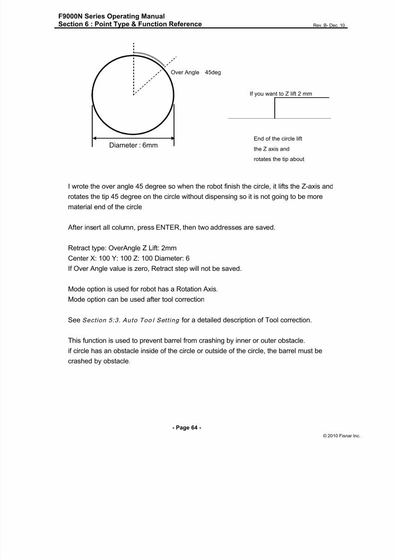
8/13/2019 Manual F9000N (RevB).pdf
http://slidepdf.com/reader/full/manual-f9000n-revbpdf 64/194
F9000N Series Operating ManualSection 6 : Point Type & Function Reference Rev. B- Dec. 10
- Page 64 -
© 2010 Fisna
Over Angle 45deg
If you want to Z lift 2 mm
Diameter : 6mm
I wrote the over angle 45 degree so when the robot finish the circle, it lifts the Z-axis and
rotates the tip 45 degree on the circle without dispensing so it is not going to be more
material end of the circle
After insert all column, press ENTER, then two addresses are saved.
Retract type: OverAngle Z Lift: 2mm
Center X: 100 Y: 100 Z: 100 Diameter: 6If Over Angle value is zero, Retract step will not be saved.
Mode option is used for robot has a Rotation Axis.
Mode option can be used after tool correction
See Section 5:3. Auto Too l Sett ing for a detailed description of Tool correction.
This function is used to prevent barrel from crashing by inner or outer obstacle.
if circle has an obstacle inside of the circle or outside of the circle, the barrel must be
crashed by obstacle.
End of the circle lift
the Z axis and
rotates the tip about
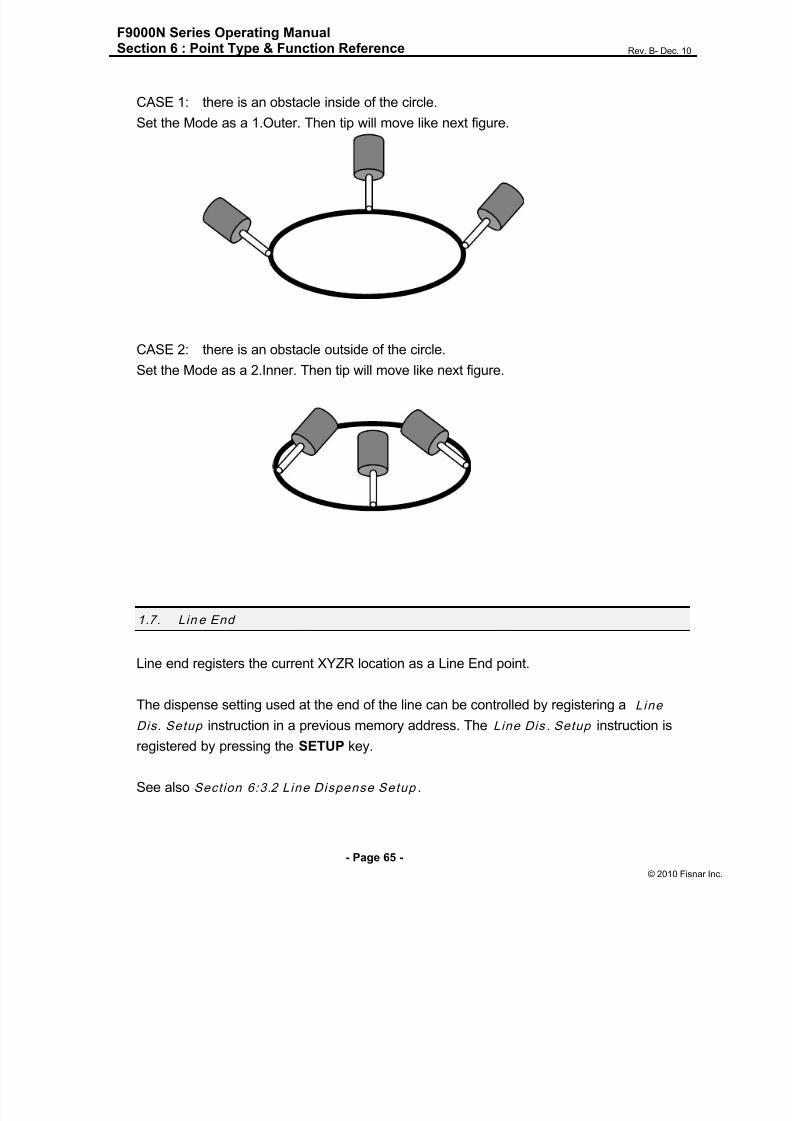
8/13/2019 Manual F9000N (RevB).pdf
http://slidepdf.com/reader/full/manual-f9000n-revbpdf 65/194
F9000N Series Operating ManualSection 6 : Point Type & Function Reference Rev. B- Dec. 10
- Page 65 -
© 2010 Fisna
CASE 1: there is an obstacle inside of the circle.
Set the Mode as a 1.Outer. Then tip will move like next figure.
CASE 2: there is an obstacle outside of the circle.Set the Mode as a 2.Inner. Then tip will move like next figure.
1.7. Lin e End
Line end registers the current XYZR location as a Line End point.
The dispense setting used at the end of the line can be controlled by registering a Line
Dis. Setup instruction in a previous memory address. The Line Dis . Setup instruction is
registered by pressing the SETUP key.
See also Section 6:3.2 Line Dispense Setup .

8/13/2019 Manual F9000N (RevB).pdf
http://slidepdf.com/reader/full/manual-f9000n-revbpdf 66/194
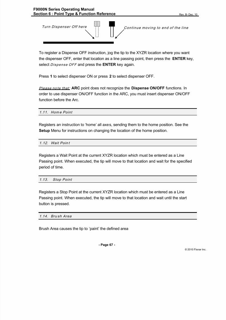
8/13/2019 Manual F9000N (RevB).pdf
http://slidepdf.com/reader/full/manual-f9000n-revbpdf 67/194
F9000N Series Operating ManualSection 6 : Point Type & Function Reference Rev. B- Dec. 10
- Page 67 -
© 2010 Fisna
To register a Dispense OFF instruction, jog the tip to the XYZR location where you want
the dispenser OFF, enter that location as a line passing point, then press the ENTER key,
select Dispense OFF and press the ENTER key again.
Press 1 to select dispenser ON or press 2 to select dispenser OFF.
Please no te that: ARC point does not recognize the Dispense ON/OFF functions. In
order to use dispenser ON/OFF function in the ARC, you must insert dispenser ON/OFF
function before the Arc.
1.11. Hom e Point
Registers an instruction to „home‟ all axes, sending them to the home position. See the
Setup Menu for instructions on changing the location of the home position.
1.12. Wait Poin t
Registers a Wait Point at the current XYZR location which must be entered as a Line
Passing point. When executed, the tip will move to that location and wait for the specified
period of time.
1.13. Stop Point
Registers a Stop Point at the current XYZR location which must be entered as a Line
Passing point. When executed, the tip will move to that location and wait until the startbutton is pressed.
1.14. Bru sh Area
Brush Area causes the tip to „paint‟ the defined area
Turn Dispenser Off here Cont inue mov ing to end of the l ine

8/13/2019 Manual F9000N (RevB).pdf
http://slidepdf.com/reader/full/manual-f9000n-revbpdf 68/194

8/13/2019 Manual F9000N (RevB).pdf
http://slidepdf.com/reader/full/manual-f9000n-revbpdf 69/194
F9000N Series Operating ManualSection 6 : Point Type & Function Reference Rev. B- Dec. 10
- Page 69 -
© 2010 Fisna
If for example, a brush width of 2 mm and brush distance of 4 mm are entered, the tip will
make the following path when the program is run:
Brush Area: Circle
Press ENT, and then press the PgDn key to scroll down to page 4/5 of the Point Menu.
Select Brush Area , then press 2 to select Circle.
You will be prompted to enter the brush width and the brush distance. The brush width is
the distance between two consecutive passings of the tip during brushing.
The brush distance is the distance between the first and the last passing of the tip during
brushing. Type the value you wish to use for the brush width and brush distance and press
ENT. (If “0” is entered for the brush distance, the entire area of the circle will be brushed).
Then teach a Line Start point on the exterior line of the circular surface to be brushed and
a Line End point in the center of that surface ( the tip will not dispense a straight line
between these two points):
2 mm
4 mm
Paint
Area
Line Start Line End
Distance
Line Start
Line End
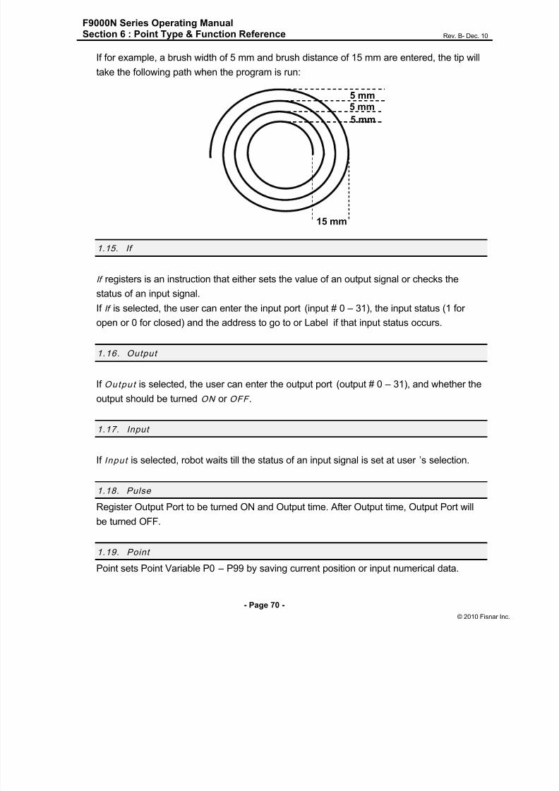
8/13/2019 Manual F9000N (RevB).pdf
http://slidepdf.com/reader/full/manual-f9000n-revbpdf 70/194

8/13/2019 Manual F9000N (RevB).pdf
http://slidepdf.com/reader/full/manual-f9000n-revbpdf 71/194
F9000N Series Operating ManualSection 6 : Point Type & Function Reference Rev. B- Dec. 10
- Page 71 -
© 2010 Fisna
2. Condit ion Menu
2.1. Goto Add ress
Goto Address causes the program to jump to the specified memory address or Label.
2.2. Step & Repeat Y
Step & Repeat Y allows a group of instructions to be run repeatedly, stepping a given
distance in the X axis or Y axis between each cycle.
Step & Repeat Y is useful when a fixture is mounted on the robot that holds many identicalwork pieces aligned in rows and columns. The user needs only to create a program for the
first work piece in the fixture, and then use the Step & Repeat function to dispense to the
other work pieces.
The Step & Repeat function will allow the user to define the number of rows, the number of
columns, the X offset between each part and the Y offset between each part.
If, for example, we have a program (for instance: program number 20) which has to
dispense four dots of material on a work piece:
The program would consist of the following eight instructions:
Address Ins t ruc t ion
0 Dispense End Setup:H.Speed = 100 mm/s, L.Speed = 15 mm/s, L.Length = 5mm
1Z Clearance:
Relative 10 mm
2Point Dispense Setup:
Dis.Time = 0.25 s Tail Time = 0.10 s
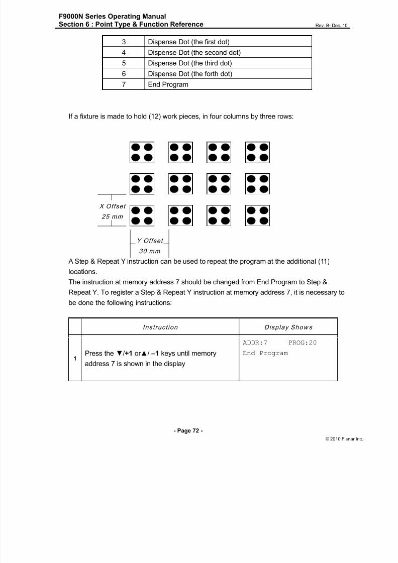
8/13/2019 Manual F9000N (RevB).pdf
http://slidepdf.com/reader/full/manual-f9000n-revbpdf 72/194
F9000N Series Operating ManualSection 6 : Point Type & Function Reference Rev. B- Dec. 10
- Page 72 -
© 2010 Fisna
3 Dispense Dot (the first dot)
4 Dispense Dot (the second dot)
5 Dispense Dot (the third dot)
6 Dispense Dot (the forth dot)
7 End Program
If a fixture is made to hold (12) work pieces, in four columns by three rows:
A Step & Repeat Y instruction can be used to repeat the program at the additional (11)locations.
The instruction at memory address 7 should be changed from End Program to Step &
Repeat Y. To register a Step & Repeat Y instruction at memory address 7, it is necessary to
be done the following instructions:
Instruct ion Display Show s
1Press the ▼/+1 or ▲/ –1 keys until memory
address 7 is shown in the display
ADDR:7 PROG:20
End Program
X Offset
25 mm
Y Offset
30 mm

8/13/2019 Manual F9000N (RevB).pdf
http://slidepdf.com/reader/full/manual-f9000n-revbpdf 73/194
F9000N Series Operating ManualSection 6 : Point Type & Function Reference Rev. B- Dec. 10
- Page 73 -
© 2010 Fisna
Instruct ion Display Show s
2
Press the F2/Cond key, select Step & Repeat Y,
select the Address, enter the number of the start
address and press ENT. The start address is the
memory address of the first instruction which is
part of this Step & Repeat group. In our example,
we want to repeat all instructions starting with
memory address number 3. Enter 3 to specify
this memory address and then press ENT.
Step & Repeat Y
Columns (X):
Rows (Y):
3
Enter 3 again, this time to specify the three
locations on the X axis direction and then press
ENT. Although we are prompted here to enter the
number of the columns, we will have to take into
account the significance of the X axis displayed
together with the word “columns” i.e. we will have
to enter the number of locations on the X axis
direction.
Step & Repeat YColumns (X):3
Rows (Y) :
4
Enter 4 to specify the four locations on the Y axis
direction and then press ENT. Although we are
prompted here to enter the number of the rows,
we will have to take into account the significance
of the Y axis displayed together with the word
“rows” i.e. we will have to enter the number of
locations on the Y axis direction.
Step & Repeat Y
X Offset: (mm)
Y Offset: (mm)
5
In the above example, the Y Offset between
parts is 30 mm.
Type 30 to specify an Y Offset of 30 mm, then
press ENT.
Step & Repeat Y
X Offset:30 (mm)
Y Offset: (mm)
6
In the above example, the X Offset between
parts is 25 mm.
Type 25 to specify an X Offset of 25 mm, and
then press ENT.
Step & Repeat Y
1. N Path
2. S Path
Select:

8/13/2019 Manual F9000N (RevB).pdf
http://slidepdf.com/reader/full/manual-f9000n-revbpdf 74/194
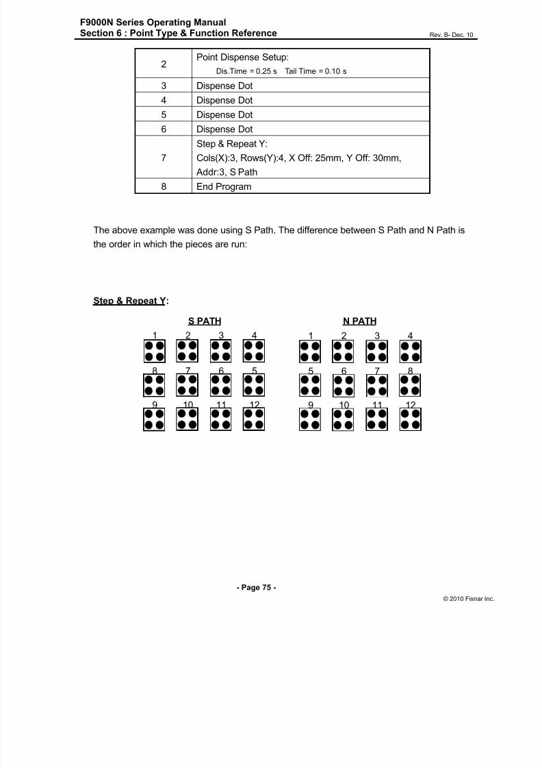
8/13/2019 Manual F9000N (RevB).pdf
http://slidepdf.com/reader/full/manual-f9000n-revbpdf 75/194
F9000N Series Operating ManualSection 6 : Point Type & Function Reference Rev. B- Dec. 10
- Page 75 -
© 2010 Fisna
2Point Dispense Setup:
Dis.Time = 0.25 s Tail Time = 0.10 s
3 Dispense Dot
4 Dispense Dot
5 Dispense Dot6 Dispense Dot
7
Step & Repeat Y:
Cols(X):3, Rows(Y):4, X Off: 25mm, Y Off: 30mm,
Addr:3, S Path
8 End Program
The above example was done using S Path. The difference between S Path and N Path is
the order in which the pieces are run:
Step & Repeat Y:
1 2 3 4
5 6 7 8
9 10 11 12
N PATH
1 2 3 4
8 7 6 5
9 10 11 12
S PATH

8/13/2019 Manual F9000N (RevB).pdf
http://slidepdf.com/reader/full/manual-f9000n-revbpdf 76/194
F9000N Series Operating ManualSection 6 : Point Type & Function Reference Rev. B- Dec. 10
- Page 76 -
© 2010 Fisna
2.3. Step & Repeat X
Step & Repeat X works just as Step & Repeat Y does, with one difference: priority is given
to the X axis instead of the Y axis.
2.4. Cal l Sub rou tine
Cal l Subrou t ine causes the machine to jump to a specified memory address and execute
the instructions found there using coordinates specified at the Call Subrou t ine instruction.
When the End Program instruction for the subroutine is reached, program execution willcontinue at the address immediately after the Cal l Subrou t ine instruction.
The Cal l Subrou t ine function is most useful to repeat a pattern anywhere on the work-
piece, as opposed to the Step & Repeat function where the pattern must be repeated in
straight lines, at fixed distances from each other.
The following example illustrates the use of the Call Subroutine instruction. An
explanation follows.
Address Ins t ruc t ion
0 Line Speed = 20
1 Call Subroutine (X1,Y1,Z1) address 6
2 Call Subroutine (X2,Y2,Z2) address 6
3 Call Subroutine (X3,Y3,Z3) address 6
1 2 3 4
8 7 6 5
9 10 11 12
Step & Repeat Y - S PATH
1 6 7 12
2 5 8 11
3 4 9 10
Step & Repeat X - S PATH

8/13/2019 Manual F9000N (RevB).pdf
http://slidepdf.com/reader/full/manual-f9000n-revbpdf 77/194
F9000N Series Operating ManualSection 6 : Point Type & Function Reference Rev. B- Dec. 10
- Page 77 -
© 2010 Fisna
4 Call Subroutine (X4,Y4,Z4) address 6
5 End Program
6 Line Start (Xs,Ys,Zs)
7 Line End (Xe,Ye,Ze)
8 End Program
2.5. Cal l Prog ram
Call Prog ram will jump to the specified program number and execute the program data inthe destination program until the End Program command is reached. When the destination
program is executed, the robot will return to the calling program.
START
Add 2
X1,Y1,Z1
Add 3
X2,Y2,Z2 Add 4
X3,Y3,Z3
Add 5
X4,Y4,Z4
END
8/13/2019 Manual F9000N (RevB).pdf
http://slidepdf.com/reader/full/manual-f9000n-revbpdf 78/194
F9000N Series Operating ManualSection 6 : Point Type & Function Reference Rev. B- Dec. 10
- Page 78 -
© 2010 Fisna
2.6. Loo p Add ress
Registers an instruction that will execute a group of instructions a user-specified number of
times.
When the Loop Address instruction is registered, the display will prompt for anAddress/Label and Count .
Address is the memory address to jump to from the current address. This address must
be less than the current memory address.
Label is the address name to jump to from the current address. This address must be less
than the current memory address.
Count is the number of times to execute the loop.
2.7. Label
Label is used instead of Address Number. A maximum of 64 Labels is permitted per
program, and each label can have up to 8 characters.
2.8. Arm
Arm command is used both for TMB Series and for F9000N Series. The use of this
command for TMB Series is different from that for F9000N Series.
In case of TMB Series, when robot moves with the command of Line/Arc , Arm command
determines position of the first and the second arm of the robot.
When Arm Lef t command is inserted before Line move command, the robot will move
Line/Arc in the minus direction of the second arm. On the contrary, Arm Right will move in
the opposite direction.
To disable Arm command, Arm No command is used.In case of F9000N Series, it allows to select between XYZ interpolation and RYZ
interpolation. Arm Left /No selects XYZ interpolation. Arm Right selects RYZ interpolation.

8/13/2019 Manual F9000N (RevB).pdf
http://slidepdf.com/reader/full/manual-f9000n-revbpdf 79/194
F9000N Series Operating ManualSection 6 : Point Type & Function Reference Rev. B- Dec. 10
- Page 79 -
© 2010 Fisna
2.9. FixR
FixR command is used for rotational axis which 4-axis robot.
FixR Fix indicates that during Line/Arc movement R axis is fixed in the same direction.
FixR No indicates that R axis moves to the point whose position was saved while robotwas moving in the Linear/Arc interpolation.
2.10. Calculat ion
For calculation, F9000N Series have 4 types of variables:
100 Integer Variables ( I0 ~ I99 ),
100 Float Variables (F0 ~ F99),
2 Timer Variables (T0,T1) ,
100 Position Variables (P0 ~ P99).
All numeric formula must have a format like this:
Variables = Variables (OK)
or
Variables = Variables ( Operator ) Variables (OK).
But it is not allowed:
Variables = Variables ( Operator ) Variables ( Operator ) Variables (NO)
Example1)
I0=1I1=I0+1
F0=I1+123.45
F1=F2/3
P0=P1
But it is not allowed:
I0=I1+I2XI3 (NO)
I4=I2XI3
I0=I1+I4 (OK)
Position Variable can be set like this:
Example2)
P0=P1
8/13/2019 Manual F9000N (RevB).pdf
http://slidepdf.com/reader/full/manual-f9000n-revbpdf 80/194
F9000N Series Operating ManualSection 6 : Point Type & Function Reference Rev. B- Dec. 10
- Page 80 -
© 2010 Fisna
P0.X=P3.X+13
P4.Y=I3/10
P3.Z=123.45
It is possible to use array.
Only Integer Variable can be Index for array
Example3)
I0=5
F[I0]=3 ( F5=3)
P[I1].X=123.4
Point Variable is used for IncJ, IncL, Jmov, Lmov
Example4)
Jmov P0
Jmov P[I0]
Variable I, F, T can be used for If command
Example5)
IF I < 50
IF F[I10] = 10
IF T0 < 100
IF I1 < I2

8/13/2019 Manual F9000N (RevB).pdf
http://slidepdf.com/reader/full/manual-f9000n-revbpdf 81/194
F9000N Series Operating ManualSection 6 : Point Type & Function Reference Rev. B- Dec. 10
- Page 81 -
© 2010 Fisna
1. Input sequence for “I10=I11+123.45”.
Instru ct ion Display Show s
1
Press Cond key and then press PgDn/+10 key
until page 3/5 is displayed.
1. FixR
2. Calc
3. Jmov
4. Lmov
2Select Calc command, by pressing 2 key.
Select Type
------------------
I F P T
3
Select Variable Type, by pressing F1/Setup
key corresponding to the letter “I‟ on the
display.
Input Number
------------------
I [I ]
4
Input Variable Number (10) by Numeric key
and then press ENT.
Select Type
------------------
I10=
I F P T
5Select Variable Type, by pressing F1/Setup
key.
Input Number
------------------
I10=I
[I ]
6
Input Variable Number (11) by Numeric key
and then press ENT.
Select Operator
------------------
I10=I11
+ - * /
7
Select Operator, by pressing F1/Setup key for
“+”. If there is no need to use operator, press
ENT.
Select Type
------------------
I10=I11+
I F P T
8Input Number (123.45) by Numeric key
and then press ENT.
Input Number
------------------
I10=I11+123.45
[I ]

8/13/2019 Manual F9000N (RevB).pdf
http://slidepdf.com/reader/full/manual-f9000n-revbpdf 82/194

8/13/2019 Manual F9000N (RevB).pdf
http://slidepdf.com/reader/full/manual-f9000n-revbpdf 83/194
F9000N Series Operating ManualSection 6 : Point Type & Function Reference Rev. B- Dec. 10
- Page 83 -
© 2010 Fisna
If Command can use variables. Here is a useful example:
If I0 < 100
If F[I10] < 123.45
If I12< I13
Instru ct ion Display Show s
1
Select ENT key and find If command and
select it.
If
------------------
2. Address
3. Label
2
Select 1 Address and input address
number, then press ENT.
Select Type
------------------
Input I F T
3
To use user input, press F1/Setup key (for
“Input”).
If not, press Function key to select Type
(I : F2 F :Inch T :Mode).
If Input
------------------
Input No:
On/Off (1/0)
4 Input Variable Number by pressing numeric
key and then ENT key.
Select Operator
------------------
I12
= < > !
5
Select Compare Operator.
= (Equal), <(Less Than), >(Greater than),!(Not
Equal)
Select Compare Type
------------------
I12<
I F
6
Press Function key to select Type
(I:F1 F:F2)
Input Number
------------------
I12<I
[I ]
7Input Variable Number by pressing numeric
key.
Input Number
------------------
I12<I13
[I ]

8/13/2019 Manual F9000N (RevB).pdf
http://slidepdf.com/reader/full/manual-f9000n-revbpdf 84/194
F9000N Series Operating ManualSection 6 : Point Type & Function Reference Rev. B- Dec. 10
- Page 84 -
© 2010 Fisna
2.11. Jmov/Lmov
This command moves to Position which is saved in the Point Variable.
In case of Jmov P0, robot moves to the point that is stored in P0.
2.12. IncJ / IncL
IncJ/IncL command moves robot to the absolute position resulted from adding a relative
position specified as an argument to the current position.
2.13. Offset
Set Offset value or point number. Every saved position after Offset command will be
increased by Offset Value.

8/13/2019 Manual F9000N (RevB).pdf
http://slidepdf.com/reader/full/manual-f9000n-revbpdf 85/194
F9000N Series Operating ManualSection 6 : Point Type & Function Reference Rev. B- Dec. 10
- Page 85 -
© 2010 Fisna
2.14. PALLET
Calculate Pallet position and input the result to Position Variable.
First of all, input the number of columns and rows of pallet.
Three corner points of the Pallet are saved as three continuous Position Variables.The first point is called “Base Point”.
Base Point can be selected from P0 to P97.
If Base Point is in P1, last unit position of column direction is saved in P2. Last unit position
of row direction is saved in P3.
Set Point is Position Variable that will save Pallet position calculation results.
Input index variable to determine the work sequence number. Index variables use integer
variables. Index variables can be selected from I0 to I99.
Next figure shows: 4 X 3 Pallet. Base Point is P1, Set Point is P0, Index is I0.
If value of I0 is 0, P0 has position of P1. If I0 is 1, P0 saves position of unit A. If I0 is 2, P0
saves position of unit C.
Value of I0 is not added automatically. Program must have command like: “I0=I0+1”.
To save position of P1, P2, P3:
CP3
A BP1 P2

8/13/2019 Manual F9000N (RevB).pdf
http://slidepdf.com/reader/full/manual-f9000n-revbpdf 86/194
F9000N Series Operating ManualSection 6 : Point Type & Function Reference Rev. B- Dec. 10
- Page 86 -
© 2010 Fisna
Instru ct ion Display Show s
1Move to P1 position and press ENT. Select
Point Command (page 5 of the Menu).
Point
Point No :
2 Input “1” by numeric key and press ENT.
Point No 1
X:0 Y:0
Z:0 R:0
[Cur]
3
Display shows current saved position of P1. To
save current position, press F1.
To edit current saved position, insert new value
by numeric key. Then press ENT key
------------------
Current Position
Saved
-------------------
4Current position is saved for P1.
For P2, P3 to be used the same way.
Address Ins t ruc t ion
1 I0=0
2 Jmov P4
3
Pallet
Row:4 Col: 3
Base Point: P1 Set Point P0 Index I0
4 Jmov P0
5 I0=I0+1
6 If I0<12 Goto Address 2
7 End Program

8/13/2019 Manual F9000N (RevB).pdf
http://slidepdf.com/reader/full/manual-f9000n-revbpdf 87/194
F9000N Series Operating ManualSection 6 : Point Type & Function Reference Rev. B- Dec. 10
- Page 87 -
© 2010 Fisna
Instru ct ion Display Show s
1Press Cond key and select Pallet Command
(page 4 of the Menu).
Pallet
------------------
Columns :4
Row :3
2 Input column, row number.
Pallet
Base Point :
Set Point :
Index :
3Input Base Point number.
Pallet
Base Point :1
Set Point :
Index :
4 Input Set Point number.
Pallet
Base Point :1
Set Point :0
Index :
5 Input Index number.
Pallet
Base Point :1
Set Point :0
Index :0

8/13/2019 Manual F9000N (RevB).pdf
http://slidepdf.com/reader/full/manual-f9000n-revbpdf 88/194
F9000N Series Operating ManualSection 6 : Point Type & Function Reference Rev. B- Dec. 10
- Page 88 -
© 2010 Fisna
2.15. Pattern / Pattern End
Pattern command works like “Step & Repeat X/Y” command, but it is different only
because it can skip or change the order of the repeat.
Pattern command is useful for arranging similar shapes.
At the end of Pattern, to be inserted Pattern End Command.
Pattern command has Index Variable. Index Variable can change the order of the repeat.
Index number can be used form I0 to I99.
For example, if the third (number 2 below) and the sixth (number 5 below) repeats must be
skipped:
0 1 2 3
4 5 6 7
8 9 10 11

8/13/2019 Manual F9000N (RevB).pdf
http://slidepdf.com/reader/full/manual-f9000n-revbpdf 89/194
F9000N Series Operating ManualSection 6 : Point Type & Function Reference Rev. B- Dec. 10
- Page 89 -
© 2010 Fisna
Address Ins t ruc t ion
0 I0=0
1 Pattern XCols(X): 3, Rows(Y): 4, X Off: 25mm, Y Off: 30mm, Index IO
2 Dispense Dot
3 Dispense Dot
4 Dispense Dot
5 Dispense Dot
6 I0=I0+1
7 If I0 !=2 Goto 9
8 I0=I0+1
9 If I0 !=5 Goto 11
10 I0=I0+1
11 Pattern End
12 End Program
Instruct ion Display Show s
1 Press Cond key and select Pattern command.
Pattern
------------------
X Offset:
Y Offset:
2 Insert X Offset, Y Offset.
Col :
Row :
Index:
3Input col, row value and Index Number. 1. X Start
2. Y Start
4 Select X Start or Y Start

8/13/2019 Manual F9000N (RevB).pdf
http://slidepdf.com/reader/full/manual-f9000n-revbpdf 90/194
F9000N Series Operating ManualSection 6 : Point Type & Function Reference Rev. B- Dec. 10
- Page 90 -
© 2010 Fisna
2.16. Xmov
Xmov can be used for sensor detecting of different work piece.
If sensor input is on while moving, robot will stop immediately and save current position in
P98.
#0 Jmov
#2 Jmov
`
Line Start Line End
#1 Xmov
Address Ins t ruc t ion
0 Jmov (0,0,0)
1 Xmov (0,0,100) In0 sensor input 0
2 Jmov (0,0,10)
3 P0.X = 04 P0.Y = 0
5 P0.Z= P98.Z-50
6 Offset P0
7 Line Start (10,0,50)
8 Line End (100,0,50)
Ex) if Z height of work piece is 45mm, after sensor detection, value of P98 is(0,0,45)
So value of P0 is (0,0,-5)By offset command, Line Start is (10,0,45) and Line End is (100,0,45)
Sensor detect Z height of
workpiece and save in P98

8/13/2019 Manual F9000N (RevB).pdf
http://slidepdf.com/reader/full/manual-f9000n-revbpdf 91/194
F9000N Series Operating ManualSection 6 : Point Type & Function Reference Rev. B- Dec. 10
- Page 91 -
© 2010 Fisna
3. Setup Menu
Below is a list of functions that are found under the F1/ SETUP key. These functions are all
related to the setup of dispensing parameters.
3.1. Lin e Speed
Registers the LINE SPEED used for all lines from the current memory address forward
until another Line Speed instruction is found.
3.2. Lin e Dispens e Setup
Registers the LINE DISPENSE SETUP values, which set the dispensing wait time at thestart of lines („head‟ time), waiting time at the end of lines („tail‟ time) , dispense off distance
(“tail length”) and output port number for Line and Arc dispense (“output”). The registered
values will be used from the current memory address forward until another Line Dispense
Setup instruction is found.
See Section 5:3. Line Dispense Setup for a detailed description of this function.
3.3. Point Dispen se Setup
Registers POINT DISPENSE SETUP values which set dispensing time and waiting time at
the end of dispensing („tail‟ time) for dots, output port number for dot dispense (“output”)
The registered values will be used from the current memory address forward until another
POINT DISPENSE SETUP instruction is found.
3.4. Dispen se End Setup
Dispense End Setup allows the L. Length , L. Speed and H. Speed values to be registered
at a memory address. These values will affect how far and how fast the tip rises after
dispensing. Please see Section 5:1. Dispense End Setup for a detailed description of this
function.

8/13/2019 Manual F9000N (RevB).pdf
http://slidepdf.com/reader/full/manual-f9000n-revbpdf 92/194
F9000N Series Operating ManualSection 6 : Point Type & Function Reference Rev. B- Dec. 10
- Page 92 -
© 2010 Fisna
3.5. Z Clearanc e
Z Clearance command sets the distance the tip will rise after dispensing, in order to avoid
obstacles. It is registered at a memory address. Please see Section 5:1. Dispense End
Setup and Section 5:2. Z Clearance for a detailed description of this function.
3.6. X/Y Move Speed
X/Y Move Speed sets default X and Y axes movement speed as the tip moves between
figures in a program, such as from one dispensing dot to another or from the end of one
dispensing line to the start of the next dispensing line.
3.7. Z Mov e Speed
Z Move Speed sets default Z axis movement speed as the tip moves between figures in a
program, such as from one dispensing dot to another or from the end of one dispensing
line to the start of the next dispensing line.
3.8. Hom e Posit io n
Home Position allows the user to change the location of the program home position. The
home position is the location to which the tip will move at the end of a program cycle.
To change the home position, jog the tip to the desired location for the new home position,
press the Setup key, then press and select Home Posi t ion .
NOTE: When executing a program in TEACH MODE, the robot will move to themechanical home position (X=0, Y=0, Z=0, R=0) at the start of every program cycle. When
executing a program in RUN MODE, the robot will move to the home position set under the
Setup: Home Position.
PgDn
+10

8/13/2019 Manual F9000N (RevB).pdf
http://slidepdf.com/reader/full/manual-f9000n-revbpdf 93/194
F9000N Series Operating ManualSection 6 : Point Type & Function Reference Rev. B- Dec. 10
- Page 93 -
© 2010 Fisna
3.9. Retract
The Retract function causes the tip to reverse direction backward along the dispensing
path, and upward after a line dispensing. This is useful when dispensing high viscosity or
„stringy‟ matrials, as it will lay the matrial tail down on the dispensed bead.Please see Sect ion 5: 4.Retract for additional information on the retract function.
3.10. Au to Purg e
The Auto Purge function prevents the dispending material to become harden
while robot is running. If there is no dispensing during „Wait time‟, the robot will purge the
material by „Purge time‟.
3.11. Ad just Point # 1
Saves current position and steps as a first data for Relocate Data function. Saves current
position to temporary Point # 1.
3.12. Ad just Point # 2
Saves current position and steps as a second data for Relocate Data function. Saves
current position to temporary Point # 2.
3.13. Round
A continuous path motion follows a path that smoothly connects two separate motions of a
robot without stopping by inserting a round path between the two motions. In order to make
such a smooth motion, a robot assumes that it has already moved to the target point if the
robot has moved to a certain range of the first target point and executes motion plan for the
next target point. It is Round commands that are used for setting the range

8/13/2019 Manual F9000N (RevB).pdf
http://slidepdf.com/reader/full/manual-f9000n-revbpdf 94/194

8/13/2019 Manual F9000N (RevB).pdf
http://slidepdf.com/reader/full/manual-f9000n-revbpdf 95/194
F9000N Series Operating ManualSection 6 : Point Type & Function Reference Rev. B- Dec. 10
- Page 95 -
© 2010 Fisna
3.14. Z Lif t
The Z-Lift function allows the user to move through the program from point to point without
raising the Z-axis. The function also allows the user to set the distance the Z-axis will
move before going to the next point. This function is especially useful when adjusting pre-existing points which are defined but are not accessible through direct Z-axis movement.
The default value is OFF.
1. Lifting Z : OFF
When Lifting Z is off, moving the tip from point to point will require the Z-axis to rise
according to the specified lifting length. If lifting length is set to zero, the tip will not do a Z-
axis movement to get to the next point.
Z-axis lift is off with the lifting length set to zero.
2. Lifting Z : ON
When lifting Z is on, moving the tip from point to point will require the Z-axis to rise to its
maximum height (Z = 0) before traveling the XY plane to get to the next point.
Z-axis lift is on so the tip moves to the home position first before going to the next point.

8/13/2019 Manual F9000N (RevB).pdf
http://slidepdf.com/reader/full/manual-f9000n-revbpdf 96/194
F9000N Series Operating ManualSection 6 : Point Type & Function Reference Rev. B- Dec. 10
- Page 96 -
© 2010 Fisna
4. Menu 1
4.1. Prog ram Name
Program Name allows the user to register a name for the current program. If a program
name is registered, it will appear on the display when that program is selected in Run
mode. The name of a program can be registered only after that program has been created.
4.2. Z Ax is Lim it
Z Axis Limit allows the user to limit the range of the Z axis values.
Press Menu 1 key and select 2 (on page 1/5) for Z Axis Limit. You will be prompted to
enter the two new values for the Z axis range.When you are prompted to enter the High Value, you will have to enter the desired value of
the Z axis in its higher position, which will be – in fact – the lower value of the new Z axis
range.
When you are prompted to enter the Low Value, you will have to enter the desired value of
the Z axis in its lower position, which will be – this time – the higher value of the new Z axis
range.
The Z axis range will be limited to these new values.

8/13/2019 Manual F9000N (RevB).pdf
http://slidepdf.com/reader/full/manual-f9000n-revbpdf 97/194
F9000N Series Operating ManualSection 6 : Point Type & Function Reference Rev. B- Dec. 10
- Page 97 -
© 2010 Fisna
4.3. Ini t ial Outp ut
Initial Output Status sets the ON/OFF status of the output signals at the start of each
program cycle.
Initial Output Status value is the hexadecimal representation of an 8 character value
controlling the 32 output signals.
For example,
HexaDecimal
Value
Output Status
(1 = on , 0 = OFF)
Bit31 Bit 0
0 0000 0000 0000 0000 0000 0000 0000 0000
1 0000 0000 0000 0000 0000 0000 0000 0001
2 0000 0000 0000 0000 0000 0000 0000 0010
4 0000 0000 0000 0000 0000 0000 0000 0100
8 0000 0000 0000 0000 0000 0000 0000 1000
A 0000 0000 0000 0000 0000 0000 0000 1010
B 0000 0000 0000 0000 0000 0000 0000 0000
AAAA 0000 0000 0000 0000 1010 1010 1010 1010
555555 0000 0000 0101 0101 0101 0101 0101 0101

8/13/2019 Manual F9000N (RevB).pdf
http://slidepdf.com/reader/full/manual-f9000n-revbpdf 98/194
F9000N Series Operating ManualSection 6 : Point Type & Function Reference Rev. B- Dec. 10
- Page 98 -
© 2010 Fisna
4.4. Cycle Counter
When in Run mode, the third line of the display shows the number of program cycles that
have run to completion for the current program number:Cycle Counter : X
It is possible to reset this number by selecting Menu 1, Cycle Counter . When prompted
for the New Value: , press 0 and ENT to reset the cycle counter.
It is also possible to cause an alarm to be generated after a fixed number of program
cycles. Select Menu 1, Cycle Counter . When prompted for the New Value: , type the
number of program cycles to complete before generating the alarm and press ENT.
In Run mode, when the set number of program cycles has been completed, the display will
show Counter Ful l ! And the start button will be disabled. The Cycle Counter must be reset
before the program can be run again. The Cycle Counter can also be reset using the
following procedure:
4.5. Set Password
Set Password allows the user to protect a program from editing. If the program is locked,
the user will not be able to change any of the program data. Unlocking the program will
allow the data to be changed again.
Instru ct ion Display Show s
1While in Run mode, press F3 (i.e. Inch/Menu 1)
key.
Prog:
AUTO
1. Reset counter
2. Adjust position
2Press 1 key to chose “Reset Counter” shown on
display.
Prog:
AUTO
Press Move key
Cycle Counter: 0

8/13/2019 Manual F9000N (RevB).pdf
http://slidepdf.com/reader/full/manual-f9000n-revbpdf 99/194
F9000N Series Operating ManualSection 6 : Point Type & Function Reference Rev. B- Dec. 10
- Page 99 -
© 2010 Fisna
4.6. Jog Speed
Sets the jog speed of the axes of the robot (namely, at the velocity level: high), both the
linear speed and the rotation speed (for 4-axis robots). The level of the velocity can bereduced to other two limits: middle (50% of high level) and low (10% of high level).
Although only mm/sec is displayed on the Teach Pendant as measure unit of the speeds,
the rotation speed (when applicable) will be considered as being expressed in
degrees/sec.
Note: For 4-axis robots, the rotation axis is marked with W on the keys and with R on the
display of the Teach Pendant.
4.7. Run Mod e
Determines whether the robot operates in Standalone mode (default) or Host mode or
Console mode. Host mode allows the robot to be controlled by commands sent over the
RS232 port.
4.8. Adjus t Posi t ion
Sets the position for Adjust Origin.
8/13/2019 Manual F9000N (RevB).pdf
http://slidepdf.com/reader/full/manual-f9000n-revbpdf 100/194
F9000N Series Operating ManualSection 6 : Point Type & Function Reference Rev. B- Dec. 10
- Page 100 -
© 2010 Fisna
4.9. Parameter
Sets the parameters of the unit. To have access to these data you are prompted to insert
the current password of the unit.
Robot Type Set
Selects the robot model / type.
Motor Setting
Sets: motor power, motor brake, encoder (pulse/rev), other spec.
Reduction Ratio
Sets the reduction ratio of each axis.
Origin Offset Set
Moves the Origin Position to proper position.
Gain Setting
Changes the Motor Gain.
Speed Set
Changes the maximum speed, acceleration time, inching speed, round set for
velocity, acceleration option set.
Brake Time Set
Selects the brake On/Off delay.Tool Setting
Sets: Tool Offset.
RS-232C
Changes the serial port setting.
Origin Setting
Changes the origin speed, origin process, origin mode.
H/W Test
Checks the hardware status: servo func., system input, servo R/W test, sensor,
origin,
servo led.
Encoder Preset (TMB Series Only)
Resets the absolute encoder error.

8/13/2019 Manual F9000N (RevB).pdf
http://slidepdf.com/reader/full/manual-f9000n-revbpdf 101/194

8/13/2019 Manual F9000N (RevB).pdf
http://slidepdf.com/reader/full/manual-f9000n-revbpdf 102/194
F9000N Series Operating ManualSection 6 : Point Type & Function Reference Rev. B- Dec. 10
- Page 102 -
© 2010 Fisna
4.10. Au to Tool Sett ing
This function can be used in Menu1>Parameter>Tool Setting.
In order to get an accurate offset of a tool attached to the end of the rotational axis of a
manipulator, three positions are necessary to be taught for one point with differentorientation of the manipulator.
This function automatically calculates and sets X and Y value of tool offset from the taught
three positions.
Teach three position for one same position with the tool mounted on the end of a
manipulator one by one. the angle between three positions should be greater than 90
degree in the following figure so that the offset value of the tool can be calculated as
accurate as possible.
In the menu, after teaching a point, press F4 PNT key to save the current position. The
message “PNT1” for the first position will change to “PNT2” for the second position and
“PNT3” for the third position each time the F4 key is pressed
After teaching all three position with different orientations, press ESC key and select 1.Yes
to calculate the offset of the attached tool.
Orientation 3
Orientation 1 Orientation 2

8/13/2019 Manual F9000N (RevB).pdf
http://slidepdf.com/reader/full/manual-f9000n-revbpdf 103/194

8/13/2019 Manual F9000N (RevB).pdf
http://slidepdf.com/reader/full/manual-f9000n-revbpdf 104/194
F9000N Series Operating ManualSection 6 : Point Type & Function Reference Rev. B- Dec. 10
- Page 104 -
© 2010 Fisna
.
For tool setting, next conditions must be satisfied.
1. The rotation direction of R axis must be from +X to +Y.
X+
-W Y+
Y- +W
X-
2. The angle between three Orientation positions should be greater than 90 degree.
4.11. Resume
Once a program has been interrupted, the Resume setting will determine if the program
restarts from point # 1 or from the point at which it was interrupted, such as the middle of a
program.If Resume is set to 1 and a program is stopped by an emergency stop signal or by the
enclosure door switch open signal, the program will restart from the point at which it was
interrupted when the start button is pressed.
If Resume is set to 0 and a program is stopped by an emergency stop signal or by the
enclosure door switch open signal, the program will restart from point #1.
The default value is 0 .
4.12. Origin Searching
This function makes the robot to go to the home position.
4.13. Hou r Meter
This function shows the total time the controller has been on, as well as how long the
manipulator has run.

8/13/2019 Manual F9000N (RevB).pdf
http://slidepdf.com/reader/full/manual-f9000n-revbpdf 105/194
F9000N Series Operating ManualSection 6 : Point Type & Function Reference Rev. B- Dec. 10
- Page 105 -
© 2010 Fisna
4.14. PLC File Edit
Allows the user to create and edit PLC files. For more information refer to Section 7:PLC.
4.15. I/O Mon ito rDisplays current Input/Output status.
4.16. Set Variable
Allows to insert value to Variable which is used in CALC(arithmetic).
4.17. EMG Mode
EMG Mode selects System Emergency signal of System Input as: Interlock signal or
Emergency Stop signal.

8/13/2019 Manual F9000N (RevB).pdf
http://slidepdf.com/reader/full/manual-f9000n-revbpdf 106/194
F9000N Series Operating ManualSection 6 : Point Type & Function Reference Rev. B- Dec. 10
- Page 106 -
© 2010 Fisna
5. Menu 2
5.1. Point Uti l i ty
5.1.1. MDI Mode
MDI Mode allows to modify the position of each address by numerical key input.
After pressing Menu 2 key and then entering Point Utility and MDI Mode, using the ▲/-1,
▼/+1 keys, find the address number that you want and press the ENT key. The cursor will
appear in the X position. Enter the value using the key pad on the Teach Pendant and
press ENT. Then the cursor will move to the Y position. Enter the value using the key pad
on the Teach Pendant and press ENT. The same procedure will be followed for Z and R
(for 4-axis robots) positions. When finished, you will be asked if want to save these
changes.
5.1.2. Num erical Mov e
Allows the tip to be positioned numerically by entering the desired numbers for the X, Y, Z
and R (for 4-axis robots) values.
5.1.3. Save Temp Poin t
Saves the current XYZR (for 4-axis robots) positions in a temporary memory area
numbered 1 – 9. The Save Temp Point function is also used with the Relocate Datafunction. See Sect ion 6 :5.2.3 Relocate Data .
5.1.4. Retriev e Temp Poin t
Retrieves an XYZR (for 4-axis robots) position that was stored with Save Temp Point.
5.2. Grou p Uti l i ty
5.2.1. Grou p EditGroup Edit is a powerful utility that allows several different functions to be applied to a
user-defined group of addresses. These functions include: copy, delete, move, multiply line
speed, multiply dispense time, apply X Offset, apply Y Offset, apply Z Offset, apply angle
of rotation (for 4-axis robots).

8/13/2019 Manual F9000N (RevB).pdf
http://slidepdf.com/reader/full/manual-f9000n-revbpdf 107/194
F9000N Series Operating ManualSection 6 : Point Type & Function Reference Rev. B- Dec. 10
- Page 107 -
© 2010 Fisna
5.2.1.1. Copy
For example, to use Group Edit to copy addresses 1 – 20 in the current program to
memory addresses 21 – 40:
Instru ct ion Display Show s
1
Press the MENU 2 key, then 2 to select Group
Utility and then 1 to select Group Edit. The
display will prompt the user to enter the starting
memory address of the group to edit (From ) and
the ending number of the group to edit (To ).
GROUP EDIT
FROM: ░
TO :
(0 <-> 2999)
2 Type 1 then press ENT to register 1 in From.Type 20 then press ENT to register 20 in To.
GROUP EDIT 1-20
1.Copy 4.Line SP2.Delete 5.Disp.TM
3.Move 6.Offset
3
The Group Edit menu will then appear, allowing
the user to select which function will apply to the
range of points. Press 1 to select Copy .
GROUP COPY
SOURCE 1-20
Destination:
4
The display will prompt the user to type the
destination memory address where the data will
be copied. Press the Del key when the cursor is
on the old figure to erase it, then type 21 and
press ENT to select destination memory address
number 21. For moving the cursor to be used
/SPD- and /SPD+ keys.
GROUP COPY
SOURCE 1-20
Destination:21
1.Yes 2.No
5
The display will now prompt the user to confirm
the copy. Press 1 to select Yes and perform the
copy.

8/13/2019 Manual F9000N (RevB).pdf
http://slidepdf.com/reader/full/manual-f9000n-revbpdf 108/194
F9000N Series Operating ManualSection 6 : Point Type & Function Reference Rev. B- Dec. 10
- Page 108 -
© 2010 Fisna
5.2.1.2. Delete
For example, to use Group Edit t o delete addresses 15 – 25 in the current program:
Instruct ion Display Show s
1
Press the MENU 2 key, then 2 to select Group
Utility and then 1 to select Group Edit. The
display will prompt the user to enter the starting
memory address of the group to edit (From ) and
the ending number of the group to edit (To ).
GROUP EDIT
FROM : ░
TO :
(0 <-> 2999)
2Type 15 then press ENT to register 15 in From.
Type 25 then press ENT to register 25 in To.
GROUP EDIT 15-25
1.Copy 4.Line SP
2.Delete 5.Dispen.TM
3.Move 6.Offset
3
The Group Edit menu will then appear, allowing
the user to select which function will apply to the
range of points.
Press 2 to select Delete.
GROUP DELETE
SOURCE 15-25
SELECT
1. Yes 2.No
4
The display will now prompt the user to confirm
the deletion. Press 1 to select Yes and delete thedata.
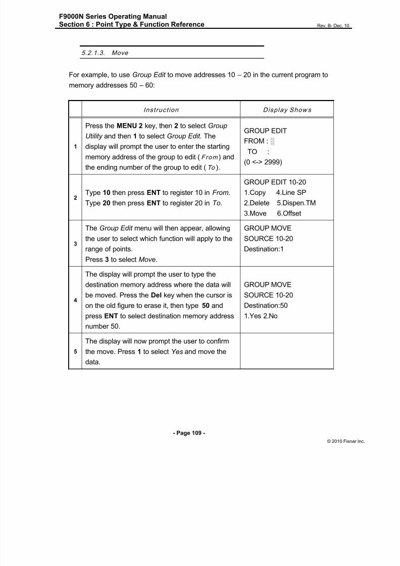
8/13/2019 Manual F9000N (RevB).pdf
http://slidepdf.com/reader/full/manual-f9000n-revbpdf 109/194
F9000N Series Operating ManualSection 6 : Point Type & Function Reference Rev. B- Dec. 10
- Page 109 -
© 2010 Fisna
5.2.1.3. Move
For example, to use Group Edit to move addresses 10 – 20 in the current program to
memory addresses 50 – 60:
Instruct ion Display Show s
1
Press the MENU 2 key, then 2 to select Group
Utility and then 1 to select Group Edit. The
display will prompt the user to enter the starting
memory address of the group to edit (From ) and
the ending number of the group to edit (To ).
GROUP EDIT
FROM : ░
TO :
(0 <-> 2999)
2Type 10 then press ENT to register 10 in From.
Type 20 then press ENT to register 20 in To.
GROUP EDIT 10-20
1.Copy 4.Line SP
2.Delete 5.Dispen.TM
3.Move 6.Offset
3
The Group Edit menu will then appear, allowing
the user to select which function will apply to the
range of points.
Press 3 to select Move.
GROUP MOVE
SOURCE 10-20
Destination:1
4
The display will prompt the user to type the
destination memory address where the data will
be moved. Press the Del key when the cursor is
on the old figure to erase it, then type 50 and
press ENT to select destination memory address
number 50.
GROUP MOVE
SOURCE 10-20
Destination:50
1.Yes 2.No
5
The display will now prompt the user to confirm
the move. Press 1 to select Yes and move thedata.

8/13/2019 Manual F9000N (RevB).pdf
http://slidepdf.com/reader/full/manual-f9000n-revbpdf 110/194
F9000N Series Operating ManualSection 6 : Point Type & Function Reference Rev. B- Dec. 10
- Page 110 -
© 2010 Fisna
5.2.1.4. Lin e SP (Lin e Speed )
For example, to use Group Edit to increase all line speed commands in memory addresses
range 1 – 200 by 20 %:
Instru ct ion Display Show s
1
Press the MENU 2 key, then 2 to select Group
Utility and then 1 to select Group Edit. The
display will prompt the user to enter the
starting memory address of the group to edit
(From ) and the ending number of the group to
edit (To ).
GROUP EDIT
FROM : ░
TO :
(0<-> 2999)
2Type 1 then press ENT to register 1 in From.
Type 200 then press ENT to register 200 in To.
GROUP EDIT 1-200
1.Copy 4.Line SP
2.Delete 5.Dispen.TM
3.Move 6.Offset
3
The Group Edit menu will then appear, allowing
the user to select which function will apply to
the range of points.
Press 4 to select Line SP .
GROUP LINE SP
Multiple Value:
4
The display will prompt the user to type the
multiple value to be applied to the line speeds.
For example, a value of 1.2 will increase all
speeds by 20%. A value of 0.8 will decrease all
speeds by 20%.
Type 1.2 and press ENT to select a multiplier of
1.2.
GROUP LINE SP
Multiple Value:1.2
SELECT
4. Yes 2.No
5
The display will now prompt the user to confirmthe change. Press 1 to select Yes.
All line speed instructions in the selected range
of addresses will now be multiplied by 1.2.
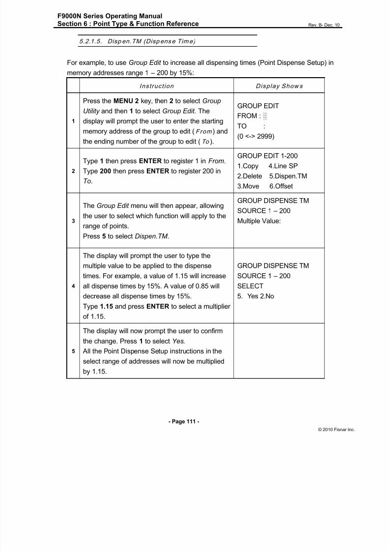
8/13/2019 Manual F9000N (RevB).pdf
http://slidepdf.com/reader/full/manual-f9000n-revbpdf 111/194
F9000N Series Operating ManualSection 6 : Point Type & Function Reference Rev. B- Dec. 10
- Page 111 -
© 2010 Fisna
5.2.1.5. Disp en.TM (Disp ense Time)
For example, to use Group Edit to increase all dispensing times (Point Dispense Setup) in
memory addresses range 1 – 200 by 15%:
Instruct ion Display Show s
1
Press the MENU 2 key, then 2 to select Group
Utility and then 1 to select Group Edit. The
display will prompt the user to enter the starting
memory address of the group to edit (From ) and
the ending number of the group to edit (To ).
GROUP EDIT
FROM : ░
TO :
(0 <-> 2999)
2
Type 1 then press ENTER to register 1 in From.
Type 200 then press ENTER to register 200 inTo.
GROUP EDIT 1-200
1.Copy 4.Line SP
2.Delete 5.Dispen.TM
3.Move 6.Offset
3
The Group Edit menu will then appear, allowing
the user to select which function will apply to the
range of points.
Press 5 to select Dispen.TM .
GROUP DISPENSE TM
SOURCE 1 – 200
Multiple Value:
4
The display will prompt the user to type themultiple value to be applied to the dispense
times. For example, a value of 1.15 will increase
all dispense times by 15%. A value of 0.85 will
decrease all dispense times by 15%.
Type 1.15 and press ENTER to select a multiplier
of 1.15.
GROUP DISPENSE TM
SOURCE 1 – 200
SELECT
5. Yes 2.No
5
The display will now prompt the user to confirm
the change. Press 1 to select Yes. All the Point Dispense Setup instructions in the
select range of addresses will now be multiplied
by 1.15.

8/13/2019 Manual F9000N (RevB).pdf
http://slidepdf.com/reader/full/manual-f9000n-revbpdf 112/194
F9000N Series Operating ManualSection 6 : Point Type & Function Reference Rev. B- Dec. 10
- Page 112 -
© 2010 Fisna
5.2.1.6. Offset
The Offset function allows all XYZR (for 4-axis robots) locations in a program to be shifted
in new XYZR locations at distances (with values) defined by the user.
For example, to use Group Edit for adding 15 mm to all X axis values in memory
addresses range 1 – 200:Instruct ion Display Show s
1
Press the MENU 2 key, then 2 to select Group
Utility and then 1 to select Group Edit. The
display will prompt the user to enter the starting
memory address of the group to edit (From ) and
the ending number of the group to edit (To ).
GROUP EDIT
FROM : ░
TO :
(1 <-> 2999)
2Type 1 then press ENTER to register 1 in From.Type 200 then press ENTER to register 200 in
To.
GROUP EDIT 1-200
1.Copy 4.Line SP
2.Delete 5.Dispen.TM
3.Move 6.Offset
3
The Group Edit menu will then appear, allowing
the user to select which function will apply to the
range of points.
Press 6 to select Offset .
GROUP OFFSET1-200
X: Y:
Z: R:
Unit: mm
4
The display will prompt the user to type the X, Y,Z and R offset amounts to be added to all points
in address range 1 – 200.
Type 15 and press ENTER to add 15 mm to the
X axis values. Press ENTER three more times to
leave the Y, Z and R offsets at zero.
GROUP OFFSET1-200
SELECT:
6. Yes 2.No
5
The display will now prompt the user to confirm
the change. Press 1 to select Yes.
15 mm will be added to all of the X axis values in
the selected range of addresses.

8/13/2019 Manual F9000N (RevB).pdf
http://slidepdf.com/reader/full/manual-f9000n-revbpdf 113/194

8/13/2019 Manual F9000N (RevB).pdf
http://slidepdf.com/reader/full/manual-f9000n-revbpdf 114/194
F9000N Series Operating ManualSection 6 : Point Type & Function Reference Rev. B- Dec. 10
- Page 114 -
© 2010 Fisna
The Expand Step & Repeat function is useful in situations where the user must edit
selected elements in a Step & Repeat group, although an expanded Step & Repeat
instruction will occupy more memory space than a an un-expanded instruction.
5.2.3. Reloc ate Data
The Relocate Data function allows the position of a program to be corrected, including
correction for X offset, Y, offset, Z offset and angle of rotation.
If, for example, the work piece fixture has been changed, the program position can be
adjusted automatically for the new fixture.
The Relocate Data function requires two reference points for the calculations. Choose two
point locations from your program that will be used as reference points. For example, to
relocate the program after a fixture change:
Instruct ion Display Show s
1
In this example, memory address 3 is the first
reference point and memory address 4 is the
second reference point.
Go to memory address 3.
2Jog the tip to the new, correct position for the first
reference point.
ADDR:3 PROG:20
Line Start
X:100.00 Y:12.54
Z:23.65 R:
3
Press the Setup key, then select Adjust point#1
to save the location and address.
This location is saved as location in temporaryposition #1.
Adjust Positon 1
Saved
----------------------

8/13/2019 Manual F9000N (RevB).pdf
http://slidepdf.com/reader/full/manual-f9000n-revbpdf 115/194
F9000N Series Operating ManualSection 6 : Point Type & Function Reference Rev. B- Dec. 10
- Page 115 -
© 2010 Fisna
Instruct ion Display Show s
4 Go to memory address 4.
ADDR:4 PROG:20
Line Passing
X:200.00 Y:112.54
Z:23.65 R:
5Jog the tip to the new, correct position for the
second reference point.
5
Press the Setup key, and then select Adjust
point#2 to save the location and address.
This location is saved as location in temporary
position #2.
Adjust Position 2
Saved
----------------------
6In Run mode. Press Menu1 key, then select
2. Adjust Position.
1.One Point
2.Two Points
SELECT:
7 Press 2 to select Two Points.
1. All Points
2. Some Points
SELECT:
8 Press 1 to select All Points Point Relocated
9 The program location will be adjusted for Xoffset, Y offset, Z offset and angle of rotation.
5.2.4. Ad just Origin
When the dispensing barrel or tip is removed and replaced, the new tip/barrel is often in a
slightly different XYZR (for 4-axis robots) position than the old tip/barrel was.
The robot has a software utility to adjust a program‟s origin, thereby correcting the tip offsetproblem.
A reference should be chosen someplace on the work piece fixture or on the work piece
itself. The reference point must be registered in the program data. This only needs to be
done one time, for example when the program is originally created.

8/13/2019 Manual F9000N (RevB).pdf
http://slidepdf.com/reader/full/manual-f9000n-revbpdf 116/194
F9000N Series Operating ManualSection 6 : Point Type & Function Reference Rev. B- Dec. 10
- Page 116 -
© 2010 Fisna
Instruct ion Display Show s
1
Jog the tip to the reference point or
if the reference point is an existing point in your
program, press the MOVE key to bring the tip to
that XYZR location.
ADDR: PROG:
EMPTY
X: Y:
Z: R:
2Press the Menu 1 key, and then on page two
select ADJUST POSITION to save the location.Set Adjust Position
When the tip/barrel is changed, use the following procedure to adjust the program origin for
the new tip location.
Instruct ion Display Show s
1While in TEACH mode, press the MENU 2 key,
then 2 to select Group Utility menu.
1.Group Edit
2.Expand Step&Repeat
3.Relocate Data
4.Adjust Origin
2 Press 4 to select Adjust Origin.
Move to First Point
X: Y:
Z: R:
Press Any Key
3
Press any key. The tip will move to the reference
point that was recorded in the Adjust Position.
If the new tip location is slightly different from the
last tip location, you should see that the tip is not
exactly at the reference point.
Adjust the First
Point
X: Y:
Z: R:
4
Jog the tip to the correct location for thereference point.
When the location is correct, press ENT.
The program origin will be adjusted for the new
tip location.
Program Data
Adjusted !!!

8/13/2019 Manual F9000N (RevB).pdf
http://slidepdf.com/reader/full/manual-f9000n-revbpdf 117/194
F9000N Series Operating ManualSection 6 : Point Type & Function Reference Rev. B- Dec. 10
- Page 117 -
© 2010 Fisna
5.3. Prog ram Uti l i ty
The Program Utility menu includes two options: Copy Program and Delete Program.
5.3.1. Copy Prog ram / Delete Prog ram
1. Copy Copies the current program number to a different program number
2. Delete Erases data in the current program number.
5.3.2. Au to Offset
Move the tip using the original coordinates stored in program memory with the MOVE
button. The next step is to jog the tip to the where it should be and the robot does all the
math on all data points to align the tip/fixture with the original program
Instruct ion Display Show s
1While in TEACH mode, press the MENU 2 key,
then 3 to select Program Utility menu.
1.Copy Porgram
2.Delete Program
3.Auto Offset
2
Press 3 to select Auto Offset .Then go to address that store reference position
with cursor key..
ADDR:0 PROG: 0 L
Line Start
X: 100 Y:100
Z: 100 R:100
3
Press Move key. The tip will move to the saved
position that was recorded in the current Address.
If the new tip location is slightly different from the
last tip location, you should see that the tip is not
exactly at the reference point.
Move New Point
X: 100 Y:100
Z: 100 R:100

8/13/2019 Manual F9000N (RevB).pdf
http://slidepdf.com/reader/full/manual-f9000n-revbpdf 118/194
F9000N Series Operating ManualSection 6 : Point Type & Function Reference Rev. B- Dec. 10
- Page 118 -
© 2010 Fisna
Instruct ion Display Show s
4
Jog the tip to the correct location for the reference
point.
When the location is correct, press ENT.
The program origin will be adjusted for the new tip
location.
Program Data
Adjusted !!!
5.4. Memo ry Uti l i ty
5.4.1. Delete Memory
Erases all programs.

8/13/2019 Manual F9000N (RevB).pdf
http://slidepdf.com/reader/full/manual-f9000n-revbpdf 119/194
F9000N Series Operating ManualSection 7 : PLC Rev. B- Dec. 10
- Page 119 -
© 2010 Fisna
Section 7:PLC

8/13/2019 Manual F9000N (RevB).pdf
http://slidepdf.com/reader/full/manual-f9000n-revbpdf 120/194
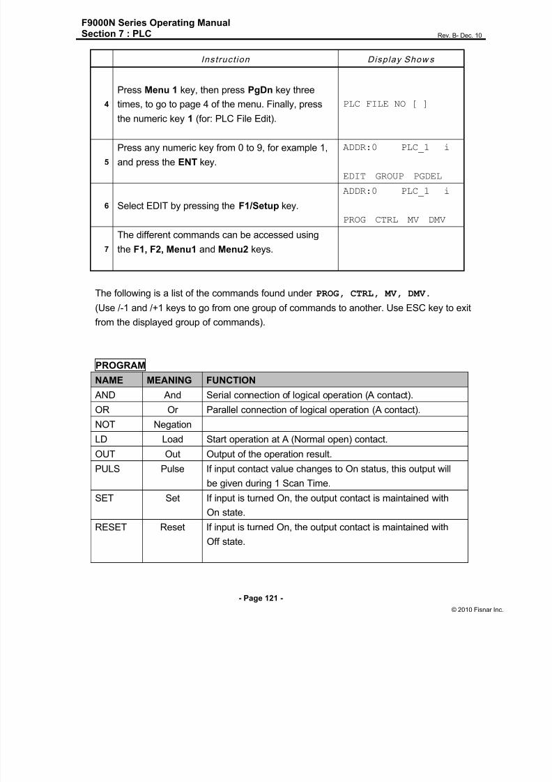
8/13/2019 Manual F9000N (RevB).pdf
http://slidepdf.com/reader/full/manual-f9000n-revbpdf 121/194

8/13/2019 Manual F9000N (RevB).pdf
http://slidepdf.com/reader/full/manual-f9000n-revbpdf 122/194
F9000N Series Operating ManualSection 7 : PLC Rev. B- Dec. 10
- Page 122 -
© 2010 Fisna
CTRL
NAME MEANING FUNCTION
T Timer This is used to control time and is On Delay Timer.
C Counter This is used to count the number and is Down Counter.
When the enable signal is turned Off, the current value will
be reset to the setting value. Input after counting is finished
will be ignored.
MC Master Control Set.
MCR MC Reset Master Control Reset.
D Data Sets Data value for counter and timer.
BK Block
END End Marks the end of the program.
MV
NAME MEANING FUNCTION
MOV Move 16bit
data
This is used to move data from a 16 bit register ( B or D )
to another 16 bit Register (B or D)
ex: MOV B100 D100 ( D100 = B100)
ADD Add two
16bit data
This is used to add data of two 16 bit register ( B or D )
and store the result to another 16 bit Register (B or D)
ex: ADD B100 D30 D40 ( D40 = B100 + D30)
SUB Subtracttwo 16bit
data
This is used to subtract data of two 16 bit register ( B or D )and store the result to another 16 bit Register (B or D)
ex: SUB B100 D30 D40 ( D40 = B100 - D30)
MUL multiply
two 16bit
data
This is used to multiply data of two 16 bit register ( B or D )
and store the result to another 16 bit Register (B or D)
ex: MUL B100 D30 D40 ( D40 = B100 x D30)
DIV divide two
16bit data
This is used to divide data of two 16 bit register ( B or D )
and store the quotient to another 16 bit Register (B or D),
remainder to Next 16bit Register (B or D)
ex: DIV B100 D30 D40 ( D40 = B100 / D30
D41 = B100 % D30)
DMV is 32 bit operation of MV function.
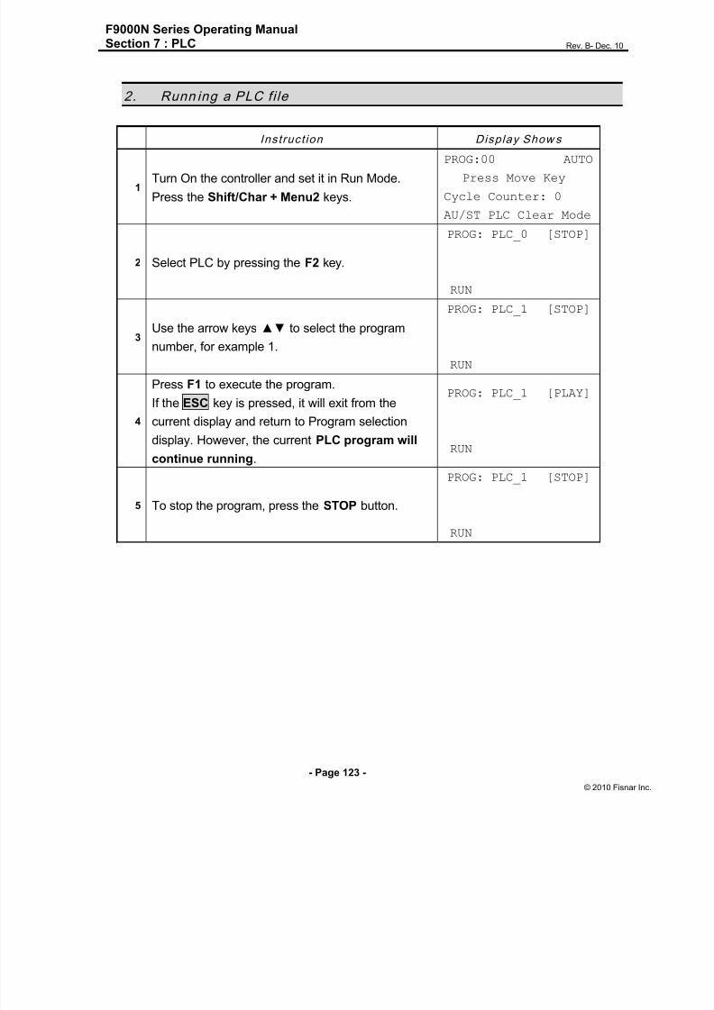
8/13/2019 Manual F9000N (RevB).pdf
http://slidepdf.com/reader/full/manual-f9000n-revbpdf 123/194

8/13/2019 Manual F9000N (RevB).pdf
http://slidepdf.com/reader/full/manual-f9000n-revbpdf 124/194
F9000N Series Operating ManualSection 7 : PLC Rev. B- Dec. 10
- Page 124 -
© 2010 Fisna
3. PLC Prog ram Examp les
3.1. LD / LDNOT /OUT
X10
Y15
X10
Y10
[Content]
If the general input 10 is turned ON, then the general output 15 is turned ON
and the general output 10 is turned OFF.
If the general input 10 is turned OFF, then the general output 15 is turned OFF
and the general output 10 is ON.
[Program]
LD X10
OUT Y15
LDNOT X10
OUT Y10
END
[Time Chart]
X10
Y15
Y10
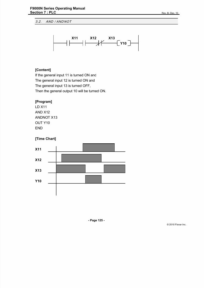
8/13/2019 Manual F9000N (RevB).pdf
http://slidepdf.com/reader/full/manual-f9000n-revbpdf 125/194
F9000N Series Operating ManualSection 7 : PLC Rev. B- Dec. 10
- Page 125 -
© 2010 Fisna
3.2. AND / ANDNOT
X11 X12 X13
Y10
[Content]
If the general input 11 is turned ON and
The general input 12 is turned ON and
The general input 13 is turned OFF,
Then the general output 10 will be turned ON.
[Program]
LD X11
AND X12
ANDNOT X13
OUT Y10
END
[Time Chart]
X11
X12
X13
Y10

8/13/2019 Manual F9000N (RevB).pdf
http://slidepdf.com/reader/full/manual-f9000n-revbpdf 126/194
F9000N Series Operating ManualSection 7 : PLC Rev. B- Dec. 10
- Page 126 -
© 2010 Fisna
3.3. OR / ORNOT
X11
Y10X12
X13
[Content]
If the general input 11 is turned ON or
The general input 12 is turned OFF or
The general input 13 is turned ON,
Then the general output 10 will be turned ON.
[Program]
LD X11
ORNOT X12
OR X13
OUT Y10END
[Time Chart]
X11
X12
X13
Y10
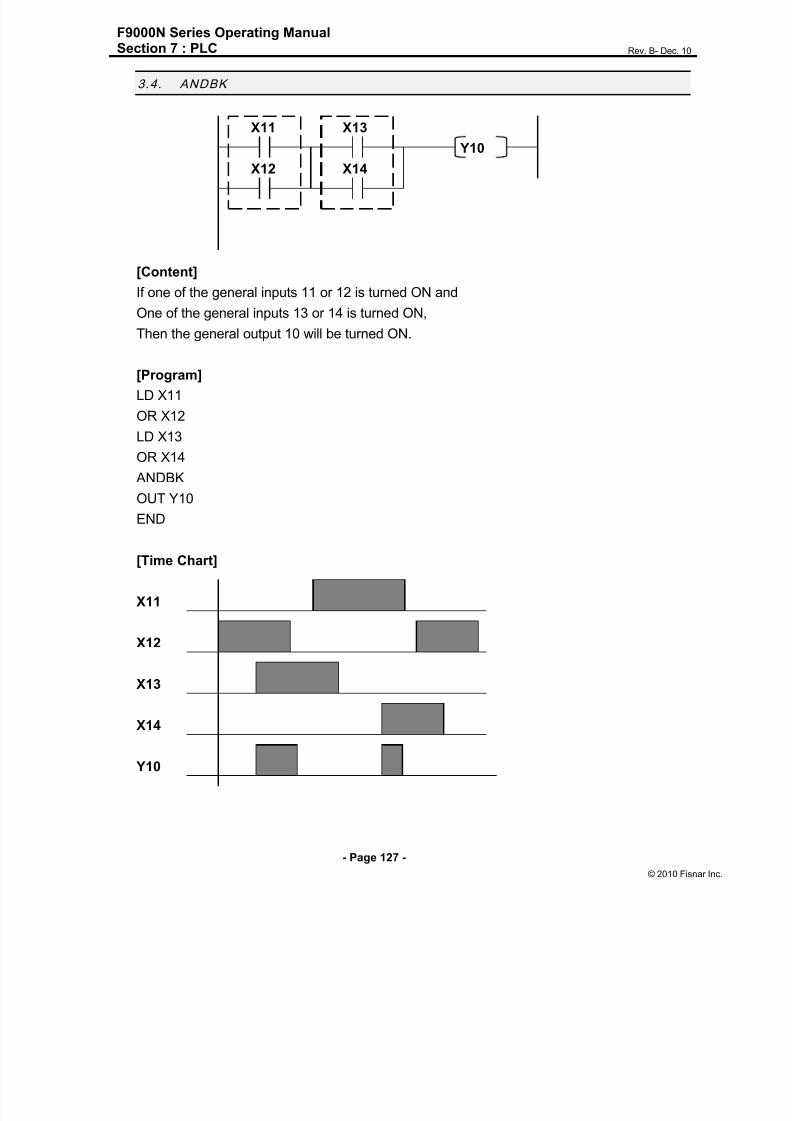
8/13/2019 Manual F9000N (RevB).pdf
http://slidepdf.com/reader/full/manual-f9000n-revbpdf 127/194
F9000N Series Operating ManualSection 7 : PLC Rev. B- Dec. 10
- Page 127 -
© 2010 Fisna
3.4. ANDBK
X11 X13
Y10
X12 X14
[Content]
If one of the general inputs 11 or 12 is turned ON and
One of the general inputs 13 or 14 is turned ON,
Then the general output 10 will be turned ON.
[Program]
LD X11
OR X12
LD X13
OR X14
ANDBK
OUT Y10
END
[Time Chart]
X11
X12
X13
X14
Y10

8/13/2019 Manual F9000N (RevB).pdf
http://slidepdf.com/reader/full/manual-f9000n-revbpdf 128/194
F9000N Series Operating ManualSection 7 : PLC Rev. B- Dec. 10
- Page 128 -
© 2010 Fisna
3.5. ORBK
X11 X12
Y10
X13 X14
[Content]
If the general input 11 is turned ON and 12 is turned ON or
The general input 13 is turned ON and 14 is turned ON,
Then the general output 10 will be turned ON.
[Program]
LD X11
AND X12
LD X13
AND X14
ORBK
OUT Y10
END
[Time Chart]
X11
X12
X13
X14
Y10

8/13/2019 Manual F9000N (RevB).pdf
http://slidepdf.com/reader/full/manual-f9000n-revbpdf 129/194
F9000N Series Operating ManualSection 7 : PLC Rev. B- Dec. 10
- Page 129 -
© 2010 Fisna
3.6. MC/MCR
X11
MC
X12 Y10
X14
Y11
MCR
[Content]
Only when the input condition of MC is turned ON, it will be run until the same MCR.
[Program]
LD X11
MC
LD X12
OUT Y10
LD X14
OUT Y11
MCR
END
[Time Chart]
X11
X12
X14
Y10
Y11

8/13/2019 Manual F9000N (RevB).pdf
http://slidepdf.com/reader/full/manual-f9000n-revbpdf 130/194

8/13/2019 Manual F9000N (RevB).pdf
http://slidepdf.com/reader/full/manual-f9000n-revbpdf 131/194
F9000N Series Operating ManualSection 7 : PLC Rev. B- Dec. 10
- Page 131 -
© 2010 Fisna
3.8. PULS/PULSNOT
X11
PULS Y10
X11
PULSNOT Y11
[Content]
If the general input 11 is turned ON, then general output 10 will be turned ON for 1PULSE
(30ms).
If the general input 11 is turned OFF, the general output 11 will be turned ON for 1PULSE
(30ms).
[Program]
LD X11
PULS Y10
LD X11
PULSNOT Y11
END
[Time Chart]
X11
Y10
30ms
Y11
30ms

8/13/2019 Manual F9000N (RevB).pdf
http://slidepdf.com/reader/full/manual-f9000n-revbpdf 132/194
F9000N Series Operating ManualSection 7 : PLC Rev. B- Dec. 10
- Page 132 -
© 2010 Fisna
3.9. T (Timer)
X11
T Y10
X12
D 300
[Content]
When the general input 11 is turned ON
and if the general input 12 is turned ON for more than 3 seconds, the general output 10 is
turned ON.
Timer is based on 10ms.
[Program]
LD X11
LD X12
T Y10
D 300 (D differs from D register. It means set timer 3 seconds)
END
[Time Chart]
X11
X12
Y10
3sec 3sec
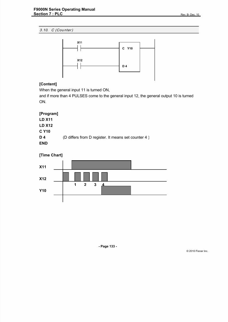
8/13/2019 Manual F9000N (RevB).pdf
http://slidepdf.com/reader/full/manual-f9000n-revbpdf 133/194
F9000N Series Operating ManualSection 7 : PLC Rev. B- Dec. 10
- Page 133 -
© 2010 Fisna
3.10. C (Counter )
X11
C Y10
X12
D 4
[Content]
When the general input 11 is turned ON,
and if more than 4 PULSES come to the general input 12, the general output 10 is turned
ON.
[Program]
LD X11
LD X12
C Y10
D 4 (D differs from D register. It means set counter 4 )
END
[Time Chart]
X11
X12
1 2 3 4
Y10

8/13/2019 Manual F9000N (RevB).pdf
http://slidepdf.com/reader/full/manual-f9000n-revbpdf 134/194
F9000N Series Operating ManualSection 7 : PLC Rev. B- Dec. 10
- Page 134 -
© 2010 Fisna
3.11. MOV / DMOV
This is used to move data from a 16/32 bit register ( B or D ) to another 16/32 bit
register (B or D).
MOV D1 D5
D1 D5
DMOV D1 D5
D1 D5
D2 D6
MOV D1 M100
D1 M115 M100
0 01 00 0 010110001
| 1 | 2 | 3 | 4 |
0X5678 0X5678
0X1234 0X1234
0X1234 0X1234
0X1234
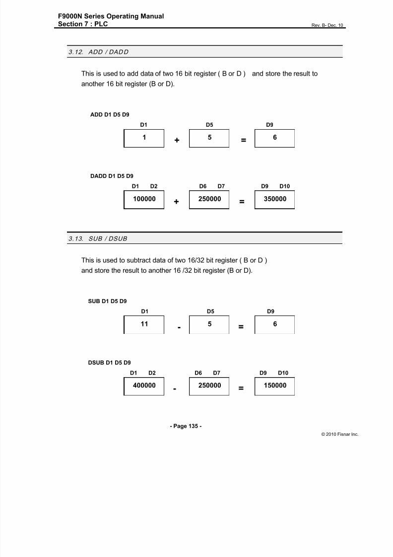
8/13/2019 Manual F9000N (RevB).pdf
http://slidepdf.com/reader/full/manual-f9000n-revbpdf 135/194

8/13/2019 Manual F9000N (RevB).pdf
http://slidepdf.com/reader/full/manual-f9000n-revbpdf 136/194
F9000N Series Operating ManualSection 7 : PLC Rev. B- Dec. 10
- Page 136 -
© 2010 Fisna
3.14. MUL/DMUL
This is used to multiply data of two 16/32 bit register ( B or D )
and store the result to another 16/32 bit register (B or D).
MUL D1 D5 D9
D1 D5 D9
x =
DMUL D1 D5 D9
D1 D2 D6 D7 D9 D10
x =
3.15. DIV / DDIV
This is used to divide data of two 16/32 bit register ( B or D )
and store the quotient to another 16/32 bit register (B or D),
remainder to next 16bit register (B or D).
DIV D1 D5 D9 quotient remainder
D1 D5 D9 D10
÷ =
DDIV D1 D5 D9 quotient remainder
D1 D2 D6 D7 D9 D10 D11 D12
÷ =
11 5 55
4000 250 1000000
11 5 2
100000 3 30000
1
10000
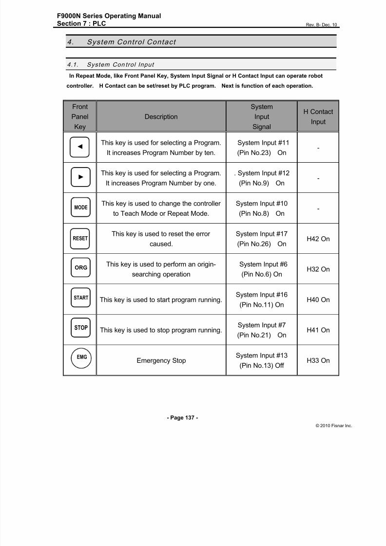
8/13/2019 Manual F9000N (RevB).pdf
http://slidepdf.com/reader/full/manual-f9000n-revbpdf 137/194
F9000N Series Operating ManualSection 7 : PLC Rev. B- Dec. 10
- Page 137 -
© 2010 Fisna
4. System Control Contact
4.1. System Con trol Input
In Repeat Mode, like Front Panel Key, System Input Signal or H Contact Input can operate robot
controller. H Contact can be set/reset by PLC program. Next is function of each operation.
Front
Panel
Key
Description
System
Input
Signal
H Contact
Input
This key is used for selecting a Program.
It increases Program Number by ten.
System Input #11
(Pin No.23) On-
This key is used for selecting a Program.
It increases Program Number by one.
. System Input #12
(Pin No.9) On-
This key is used to change the controller
to Teach Mode or Repeat Mode.
System Input #10
(Pin No.8) On-
This key is used to reset the error
caused.
System Input #17
(Pin No.26) OnH42 On
This key is used to perform an origin-
searching operation
System Input #6
(Pin No.6) OnH32 On
This key is used to start program running.System Input #16
(Pin No.11) OnH40 On
This key is used to stop program running.System Input #7
(Pin No.21) OnH41 On
Emergency StopSystem Input #13
(Pin No.13) OffH33 On
◄
►
MODE
RESET
ORG
START
STOP
EMG

8/13/2019 Manual F9000N (RevB).pdf
http://slidepdf.com/reader/full/manual-f9000n-revbpdf 138/194

8/13/2019 Manual F9000N (RevB).pdf
http://slidepdf.com/reader/full/manual-f9000n-revbpdf 139/194
F9000N Series Operating ManualSection 8 : Error List Rev. B- Dec. 10
- Page 139 -
© 2010 Fisna
Section 8:Error list

8/13/2019 Manual F9000N (RevB).pdf
http://slidepdf.com/reader/full/manual-f9000n-revbpdf 140/194
F9000N Series Operating ManualSection 8 : Error List Rev. B- Dec. 10
- Page 140 -
© 2010 Fisna
1. Error l ist for Hardware
The following Error List is about Hardware or Mechanical error.
No ErrorDisplay
Contents
01ENVLOP
ERR
MeaningThe tracking error of the position/velocity profile
exceeds the commanded value.
Cause
1. The gains of position/velocity control loop are
too low.
2. Motor connection is abnormal.
3. Servo Amp is damaged.
Action
1. Increase the proportional gains of position /
velocity control loop to more than 10% of the
present value (PP/V_P).
2. Reconnect the motor connector.
3. Contact the manufacturer/sales agent.
02 OVERSPEED
Meaning The velocity is over the commanded value.
CauseElectrical power lines of motor & encoder are
connected to other channels.
Action
Connect the connector properly and if error
reoccurs, contact the manufacturer.
03 ENC READERR
Meaning
1. Failure to detect stimulus position of initial
encoder.
2. Failure to detect position of initial absolute
encoder.
Cause
1. Disconnection or bad connection in encoderline.
2. Encoder power related abnormality.
Action1. Check encoder line.
2. Check encoder power line.

8/13/2019 Manual F9000N (RevB).pdf
http://slidepdf.com/reader/full/manual-f9000n-revbpdf 141/194
F9000N Series Operating ManualSection 8 : Error List Rev. B- Dec. 10
- Page 141 -
© 2010 Fisna
04ENC COUNT
ERR
MeaningDifference in the encoder position during one motor
rotation is over 5 pulses.
Cause
1. Disconnection or bad connection in
encoder line while driving.
2. Encoder setting abnormality.
Action
1. Check/ Reconnect the encoder line.
2. Change encoder setting related to
the counts of a rotation.
07MOTOR CUR
ERR
Meaning Excessive electric current flow in motor.
Cause
1. Acceleration and deceleration time is too short
for inertia load.
2. The electric current loop gain is
either too small or too big.
Action
1. Reset parameter related to acceleration and
deceleration.
2. Reset parameter related to gain.
08 ENC ERR
Meaning Encoder Connection is abnormal.
Cause Encoder Cable Connection is bad.
Action Check Encoder Connection.
09 OVER LOAD
Meaning Over load on rated load.
Cause
1. Friction may be too high between
machine and moving parts.
2. Acceleration and deceleration may
be frequent in short distances.
3. Inertia load may be too high.
4. Brake malfunction.
Action
1. Check moving parts in the machine.
2. Increase the acceleration and
deceleration time.
3. Reduce inertia load.
4. Check motion or change brakes.
10MISS ABS
INC
Meaning Encoder Type is not exact.
Cause Parameter setting is wrong.
Action Correct parameter.

8/13/2019 Manual F9000N (RevB).pdf
http://slidepdf.com/reader/full/manual-f9000n-revbpdf 142/194
F9000N Series Operating ManualSection 8 : Error List Rev. B- Dec. 10
- Page 142 -
© 2010 Fisna
11 H/W LIMIT
Meaning Came in contact with limit sensor.
Cause
1. Machine came in contact with the limit sensor.
2. Disconnection or Bad connection of limit
sensor line.
3. Set limit sensor as point of contact A (N,O).
4. Improper parameter setting.
Action
1. Move machine.
2. Check limit sensor line, dismount connector
and then connect again.
3. Change limit sensor to point of contact B.
4. Change parameters related to limit setting.
12 S/W LIMIT
Meaning Exceeded software limit.
Cause
1. Machine has surpassed software limit area.
2. When point of teach is close to the software
limit.
Action
1. Move the machine.
2. Change parameters related to software limit or
change point of teach.
13 INPOS ERR
MeaningThe tracking error of the position/ velocity profile
exceeds over the In position value.
Cause
1. The gains of position/velocity control loop are
too low.2. In position Value in Parameter is too small.
Action
1. Increase the proportional gains of position/
velocity control loop to more than 10% of
the present value. (PP/V_P).
2. Increase In position value in Parameter.
14 ORG ERR
MeaningOpposite direction signal input of limit sensor during
point of origin return process.
CauseIncorrect setting of origin sensor/direction.
ActionCorrect the parameter related to origin.

8/13/2019 Manual F9000N (RevB).pdf
http://slidepdf.com/reader/full/manual-f9000n-revbpdf 143/194
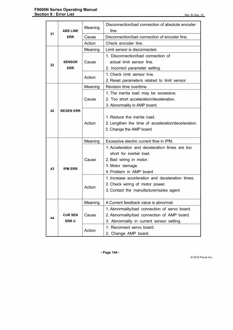
8/13/2019 Manual F9000N (RevB).pdf
http://slidepdf.com/reader/full/manual-f9000n-revbpdf 144/194
F9000N Series Operating ManualSection 8 : Error List Rev. B- Dec. 10
- Page 144 -
© 2010 Fisna
21ABS LINE
ERR
MeaningDisconnection/bad connection of absolute encoder
line.
Cause Disconnection/bad connection of encoder line.
Action Check encoder line.
22SENSOR
ERR
Meaning Limit sensor is disconnected.
Cause
1. Disconnection/bad connection of
actual limit sensor line.
2. Incorrect parameter setting.
Action1. Check limit sensor line.
2. Reset parameters related to limit sensor.
42 REGEN ERR
Meaning Revision time overtime.
Cause
1. The inertia load may be excessive.
2. Too short acceleration/deceleration.
3. Abnormality in AMP board.
Action
1. Reduce the inertia load.
2. Lengthen the time of acceleration/deceleration.
3. Change the AMP board.
43 IPM ERR
Meaning Excessive electric current flow in IPM.
Cause
1. Acceleration and deceleration times are too
short for inertial load.2. Bad wiring in motor.
3. Motor damage.
4. Problem in AMP board.
Action
1. Increase acceleration and deceleration times.
2. Check wiring of motor power.
3. Contact the manufacturer/sales agent.
44CUR SEN
ERR U
Meaning A Current feedback value is abnormal.
Cause
1. Abnormality/bad connection of servo board.
2. Abnormality/bad connection of AMP board.
3. Abnormality in current sensor setting.
Action1. Reconnect servo board.
2. Change AMP board.

8/13/2019 Manual F9000N (RevB).pdf
http://slidepdf.com/reader/full/manual-f9000n-revbpdf 145/194
F9000N Series Operating ManualSection 8 : Error List Rev. B- Dec. 10
- Page 145 -
© 2010 Fisna
45CUR SEN
ERR V
Meaning A Current feedback value is abnormal.
Cause
1. Abnormality/bad connection of servo board.
2. Abnormality/bad connection of AMP board.
3. Abnormality in current sensor setting.
Action 1. Reconnect servo board.2. Change AMP board.
62PN 240V
LOW
Meaning Voltage abnormality among PN.
Cause
1. Bridge diode abnormality.
2. Disconnection/bad connection of PN line.
3. AMP board abnormality.
Action
1. Change bridge diode.
2. Check PN line.
3. Change AMP.
63HEAT SINK
ERR
Meaning Heat Sink is overheated.
Cause Acceleration and deceleration time is too short
for inertia load.
ActionReset parameters related to acceleration and
deceleration.
64TMS
TIMEOVER
Meaning The servo board is not answering.
Cause1. Incorrect parameter setting.
2. Abnormality in servo board.
Action 1. Change parameter setting.
2. Change the servo board.
65SEMA ERR
SRV
Meaning The servo and the main board do not correlate.
Cause1. An unused axis may have been set.
2. Bad connection in servo board.
Action1. Reset parameters related to axis setting.
2. Dismount the servo board and reinstall.
66 P12V FAIL
Meaning Abnormality in +12V power (Less than 10.5V).
Cause1. Bad connection.
2. Voltage drop (Abnormal SMPS).
Action
1. Reconnect (SMPS/ Servo board).
2. Change SMPS.

8/13/2019 Manual F9000N (RevB).pdf
http://slidepdf.com/reader/full/manual-f9000n-revbpdf 146/194
F9000N Series Operating ManualSection 8 : Error List Rev. B- Dec. 10
- Page 146 -
© 2010 Fisna
67 M12V FAIL
Meaning Input voltage -12V abnormality (Less than -10.5V).
Cause
1. Bad connection.
2. Voltage drop (Abnormal SMPS).
Action1. Reconnect (SMPS/ Servo board).2. Change SMPS.
68SEMA ERR
MAIN
MeaningMain and servo board do not activate.
Cause1. Unused axes have been set as being in use.
2. Bad connection of servo board.
Action1. Reset axis parameter.
2. Dismount the servo board and then reinstall.
69AMP BD
NONE
Meaning The AMP board does not exist.
Cause1. Incorrect axis setting.
2. Bad connection of board.
Action1. Change axis setting parameter.
2. Reconnect board.
80 SYS EMG
Meaning System EMG signal is On.
Cause System EMG signal input.
Action Cancel system EMG.
81 FRONT EMG
Meaning Front EMG signal is On.
Cause Front EMG signal input.
Action Cancel front EMG.
82 T/P EMG
Meaning TP EMG signal is On.
Cause TP EMG signal input.
Action Cancel TP EMG.
84
MAIN BATT
ERR
MeaningThe main board battery has been discharged.
Cause The main board battery voltage may be lowerthan 2.4 V.
Action Check / change the main board battery voltage.
86 HOST EMG
Meaning Host EMG is On.
Cause Host EMG is On.
Action Reset Host EMG.

8/13/2019 Manual F9000N (RevB).pdf
http://slidepdf.com/reader/full/manual-f9000n-revbpdf 147/194

8/13/2019 Manual F9000N (RevB).pdf
http://slidepdf.com/reader/full/manual-f9000n-revbpdf 148/194
F9000N Series Operating ManualSection 8 : Error List Rev. B- Dec. 10
- Page 148 -
© 2010 Fisna
2. Error List For Program
2.1. Need LINE START
An attempt was made to register a Line Passing point, an Arc point or a Line End point
without first registering a Line Start point.
Register a Line Start point before registering a Line Passing point, an Arc point or a Line
End point.
2.2. Need LINE END
An attempt was made to run a program that registered a Line Passing point, an Arc pointor a Line Start point without registering a Line End point.
Register a Line End point after registering a Line Passing point, an Arc point or a Line
Start point.
2.3. Need Step & Repeat
The Expand Step & Repeat command was given but there is no Step & Repeat
instruction currently in the display. Move to the Step & Repeat function you want to
expand before selecting Expand Step & Repeat.
2.4. PROGRAM END ERROR
An attempt was made to run a program without registering a Program End.
2.5. LABL Not Exist
An attempt was made to call a label that does not exist

8/13/2019 Manual F9000N (RevB).pdf
http://slidepdf.com/reader/full/manual-f9000n-revbpdf 149/194
F9000N Series Operating ManualSection 9 : Appendix Rev. B- Dec. 10
- Page 149 -
© 2010 Fisna
Section 9: Appendix

8/13/2019 Manual F9000N (RevB).pdf
http://slidepdf.com/reader/full/manual-f9000n-revbpdf 150/194
F9000N Series Operating ManualSection 9 : Appendix Rev. B- Dec. 10
- Page 150 -
© 2010 Fisna
1. Append ix A: User I/O Board
1. Outline
User I/O board is the general Input/Output board used to interface controller andexternal device using I/O signal. The form of signal is as follows:
Digital Input: 32 contacts
Digital Output: 32 contacts
2. Structure
Input is received through photo coupler and output given by photo coupler as well.
3. Components of the structure
Device for the input: photo coupler
Device for the output: photo coupler (Darlington Transistor Output)
4. Specifications
Items User Input User Output
Rated Input/Output
voltage
D.C 24[V]
Rated Input/Output
current
Min. 5[mA] / 1
contact
Max. 50 [mA] / 1
contact
Insulation method
(Photo coupler)
Input: Insulation voltage (2000 [Vrms])
Output: Insulation voltage (2000 [Vrms])
Number of
Input/Output contacts
32 contacts 32 contacts
Internal Input/Output
voltage
(Output current)
D.C 24[V] (Max. 600[mA])
5. Connectors and Input/Output Circuit Diagram
CN2: External Input Interface Connector
CN3: External Output Interface Connector

8/13/2019 Manual F9000N (RevB).pdf
http://slidepdf.com/reader/full/manual-f9000n-revbpdf 151/194
F9000N Series Operating ManualSection 9 : Appendix Rev. B- Dec. 10
- Page 151 -
© 2010 Fisna
User I/O Board External Connections
P-COM1 (5)*
IN0 (1)
IN1 (2)
IN2 (3)
IN3 (18)
IN4 (33)
IN5 (34)
IN6 (19)
IN7 (4)
P-COM2 (8)
IN8 (20)
IN9 (35)
IN10 (36)
IN11 (21)
IN12 (6)
IN13 (7)
IN14(22)
IN15 (37)
Internal Power of Controller
(Max. 600[mA])
24[V] (16, 31)
24[G] (15, 30)
JP3
3
1
Internal 24V
External 24V
External 24VJP2
3
1
1) Input Circuit and External Interface Circuit (1st ~16th contact): CN2 Connector
Note: ( )* is the Pin Number of the Connector.

8/13/2019 Manual F9000N (RevB).pdf
http://slidepdf.com/reader/full/manual-f9000n-revbpdf 152/194
F9000N Series Operating ManualSection 9 : Appendix Rev. B- Dec. 10
- Page 152 -
© 2010 Fisna
Input Circuit and External Interface Circuit (17th ~ 32nd contact): CN2 Connector
Note: ( )* is the Pin Number of the Connector.
User I/O Board External Connections
P-COM3 (11)*
IN16 (23)
IN17 (38)
IN18 (39)
IN19 (24)
IN20 (9)
IN21 (10)
IN22 (25)
IN23 (40)
P-COM4 (29)
IN24 (26)
IN25 (41)
IN26 (42)
IN27 (27)
IN28 (12)
IN29 (28)
IN30 (43)
IN31 (44)
Internal Power of Controller
(Max. 600[mA])
24[V] (16, 31)
24[G] (15, 30)
JP4
3
1
JP5
3
1
iInternal 24V
External 24V
External 24V

8/13/2019 Manual F9000N (RevB).pdf
http://slidepdf.com/reader/full/manual-f9000n-revbpdf 153/194

8/13/2019 Manual F9000N (RevB).pdf
http://slidepdf.com/reader/full/manual-f9000n-revbpdf 154/194
F9000N Series Operating ManualSection 9 : Appendix Rev. B- Dec. 10
- Page 154 -
© 2010 Fisna
Output Circuit and External Interface Circuit (17th ~32nd contact): CN3 Connector
Note: ( )* is the Pin Number of the Connector.
User I/O Board External Connections
OUT16 (23)*
OUT17 (38)
OUT18 (39)
OUT19 (24)
OUT20 (9)
OUT21 (10)
OUT22 (25)
OUT23 (40)
N-COM3 (11)
OUT24 (26)
OUT25 (41)
OUT26 (42)
OUT27 (27)
OUT28 (12)
OUT29 (28)
OUT30 (43)
OUT31 (44)
N-COM4 (29)
Internal Power of Controller (Max. 600[mA])
24[V] (16, 31)
24[G] (15, 30)
Relay
Relay
Relay
Relay
Relay
Relay
Relay
Relay
Relay
Relay
Relay
Relay
Relay
Relay
Relay
Note) In case of inductive load(ex: relay), insert a diode as shown in the figure.
Relay
JP8
3
1
JP9
3
1
Internal 24G
External 24V
External 24V

8/13/2019 Manual F9000N (RevB).pdf
http://slidepdf.com/reader/full/manual-f9000n-revbpdf 155/194
F9000N Series Operating ManualSection 9 : Appendix Rev. B- Dec. 10
- Page 155 -
© 2010 Fisna
6. In/Output Signal Name
1) Input Signal Name
No. I/O Sign Explanation
16, 31 Internal power 24[V] D.C 24[V] Internal Power
15, 30 Internal grounding 24[G] D.C 24[G] Internal Ground1 Input IN 0 INPUT 1
2 Input IN 1 INPUT 2
3 Input IN 2 INPUT 3
18 Input IN 3 INPUT 4
33 Input IN 4 INPUT 5
34 Input IN 5 INPUT 6
19 Input IN 6 INPUT 7
4 Input IN 7 INPUT 85 P-COM1 24[V] Common
20 Input IN 8 INPUT 9
35 Input IN 9 INPUT 10
36 Input IN 10 INPUT 11
21 Input IN 11 INPUT 12
6 Input IN 12 INPUT 13
7 Input IN 13 INPUT 14
22 Input IN 14 INPUT 1537 Input IN 15 INPUT 16
8 P-COM2 24[V] Common
23 Input IN 16 INPUT 17
38 Input IN 17 INPUT 18
39 Input IN 18 INPUT 19
24 Input IN 19 INPUT 20
9 Input IN 20 INPUT 21
10 Input IN 21 INPUT 22
25 Input IN 22 INPUT 23
40 Input IN 23 INPUT 24
11 P-COM3 24[V] Common
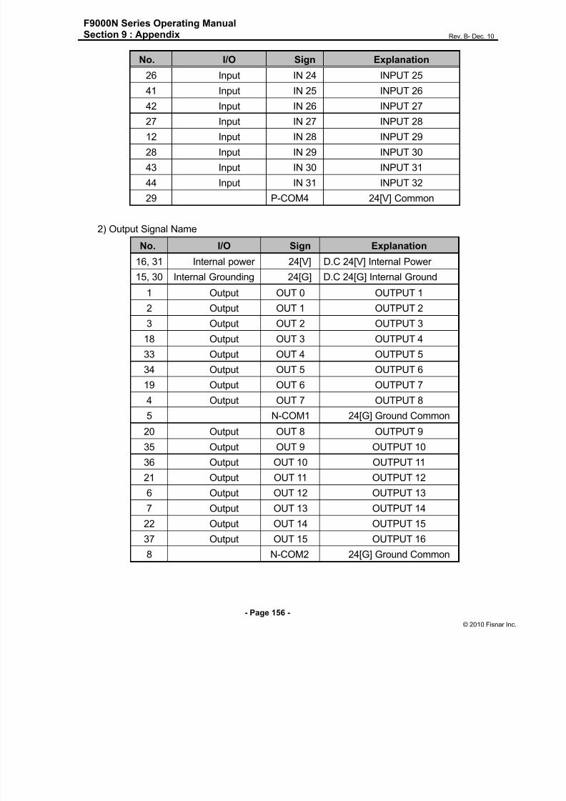
8/13/2019 Manual F9000N (RevB).pdf
http://slidepdf.com/reader/full/manual-f9000n-revbpdf 156/194
F9000N Series Operating ManualSection 9 : Appendix Rev. B- Dec. 10
- Page 156 -
© 2010 Fisna
No. I/O Sign Explanation
26 Input IN 24 INPUT 25
41 Input IN 25 INPUT 26
42 Input IN 26 INPUT 27
27 Input IN 27 INPUT 2812 Input IN 28 INPUT 29
28 Input IN 29 INPUT 30
43 Input IN 30 INPUT 31
44 Input IN 31 INPUT 32
29 P-COM4 24[V] Common
2) Output Signal Name
No. I/O Sign Explanation16, 31 Internal power 24[V] D.C 24[V] Internal Power
15, 30 Internal Grounding 24[G] D.C 24[G] Internal Ground
1 Output OUT 0 OUTPUT 1
2 Output OUT 1 OUTPUT 2
3 Output OUT 2 OUTPUT 3
18 Output OUT 3 OUTPUT 4
33 Output OUT 4 OUTPUT 5
34 Output OUT 5 OUTPUT 619 Output OUT 6 OUTPUT 7
4 Output OUT 7 OUTPUT 8
5 N-COM1 24[G] Ground Common
20 Output OUT 8 OUTPUT 9
35 Output OUT 9 OUTPUT 10
36 Output OUT 10 OUTPUT 11
21 Output OUT 11 OUTPUT 12
6 Output OUT 12 OUTPUT 13
7 Output OUT 13 OUTPUT 14
22 Output OUT 14 OUTPUT 15
37 Output OUT 15 OUTPUT 16
8 N-COM2 24[G] Ground Common

8/13/2019 Manual F9000N (RevB).pdf
http://slidepdf.com/reader/full/manual-f9000n-revbpdf 157/194
F9000N Series Operating ManualSection 9 : Appendix Rev. B- Dec. 10
- Page 157 -
© 2010 Fisna
No. I/O Sign Explanation
16, 31 Internal Power 24[V] D.C 24[V] Internal Power
15, 30 Internal Grounding 24[G] D.C 24[G] Internal Ground
23 Output OUT 16 OUTPUT 17
38 Output OUT 17 OUTPUT 18
39 Output OUT 18 OUTPUT 19
24 Output OUT 19 OUTPUT 20
9 Output OUT 20 OUTPUT 21
10 Output OUT 21 OUTPUT 22
25 Output OUT 22 OUTPUT 23
40 Output OUT 23 OUTPUT 24
11 N-COM3 24[G] Ground Common
26 Output OUT 24 OUTPUT 25
41 Output OUT 25 OUTPUT 26
42 Output OUT 26 OUTPUT 27
27 Output OUT 27 OUTPUT 28
12 Output OUT 28 OUTPUT 29
28 Output OUT 29 OUTPUT 30
43 Output OUT 30 OUTPUT 31
44 Output OUT 31 OUTPUT 32
29 N-COM4 24[G] Ground Common

8/13/2019 Manual F9000N (RevB).pdf
http://slidepdf.com/reader/full/manual-f9000n-revbpdf 158/194
F9000N Series Operating ManualSection 9 : Appendix Rev. B- Dec. 10
- Page 158 -
© 2010 Fisna
7. Pin Arrangement and Specification of the Connector
Connector specification:
CN2: D-Sub, 44Pin, Female, Right Angle Type
CN3: D-Sub, 44Pin, Male, Right Angle Type
Note 1: When you connect the CN2 connector with external device, use D-Sub,
44Pin, Male, Solder Type.
Note 2: When you connect the CN3 connector with external device, use D-Sub,
44Pin, Female, Solder Type.
Note 3: When you wire the external power, please make sure the connection of D.C
24[V] polarity is properly assigned.
Note 4: If wiring is not properly done, the internal circuit element may be damaged.
Take precaution of the polarity of the common terminal.
1
16
31
1530
44
1
31
15
16
30
44
Input Connector (CN2) Output Connector (CN3)

8/13/2019 Manual F9000N (RevB).pdf
http://slidepdf.com/reader/full/manual-f9000n-revbpdf 159/194
F9000N Series Operating ManualSection 9 : Appendix Rev. B- Dec. 10
- Page 159 -
© 2010 Fisna
8. Jumper Setting
No. Sign Setting
JP2 24[V] Common (P-COM1)No. 1-2 Short : internal power use
No. 2-3 Short : external power use
JP3 24[V] Common (P-COM2)No. 1-2 Short : internal power use
No. 2-3 Short : external power use
JP4 24[V] Common (P-COM3)No. 1-2 Short : internal power use
No. 2-3 Short : external power use
JP5 24[V] Common (P-COM4)No. 1-2 Short : internal power use
No. 2-3 Short : external power use
JP6 24[G] Ground Common (N-COM1)
No. 1-2 Short : internal grounding use
No. 2-3 Short : external grounding use
JP724[G] Ground Common (N-
COM2)
No. 1-2 Short : internal grounding use
No. 2-3 Short : external grounding use
JP824[G] Ground Common (N-
COM3)
No. 1-2 Short : internal grounding use
No. 2-3 Short : external grounding use
JP924[G] Ground Common (N-
COM4)
No. 1-2 Short : internal grounding use
No. 2-3 Short : external grounding use
Note: When the product is delivered, the jumper of the external power and grounding
has been set in advance. Please use the jumper setting as external power and
grounding if possible, and refrain from using internal power and grounding.
CN
2
JP6
CN
3
JP7
JP8
JP9
JP5
JP4
JP3
JP2

8/13/2019 Manual F9000N (RevB).pdf
http://slidepdf.com/reader/full/manual-f9000n-revbpdf 160/194

8/13/2019 Manual F9000N (RevB).pdf
http://slidepdf.com/reader/full/manual-f9000n-revbpdf 161/194
F9000N Series Operating ManualSection 9 : Appendix Rev. B- Dec. 10
- Page 161 -
© 2010 Fisna
1) Input Circuit and External Interface Circuit (1st ~16th contact)
Note: ( )* is the Pin Number of the Connector.
System I/O Board External Connections
P-COM1 (33)*
PGM0 (3)
PGM1 (18)
PGM2 (4)
PGM3 (19)
PGM4 (5)
PGM-SEL (20)
ORIGIN (6)
STOP (21)
P-COM2 (34)
MOD-SEL (8)
MOVE- (23)
MOVE+ (9)
Internal Power of Controller
(Max. 600[mA])
24[V] (16, 31)
24[G] (17, 32)
Internal 24V
JP4
3
1
External 24V
External 24VJP5
3
1

8/13/2019 Manual F9000N (RevB).pdf
http://slidepdf.com/reader/full/manual-f9000n-revbpdf 162/194

8/13/2019 Manual F9000N (RevB).pdf
http://slidepdf.com/reader/full/manual-f9000n-revbpdf 163/194
F9000N Series Operating ManualSection 9 : Appendix Rev. B- Dec. 10
- Page 163 -
© 2010 Fisna
2) Output Circuit and External Interface Circuit (1st ~ 6th contact)
Note 2: ( )* is the Pin Number of the Connector.
System I/O Board External Connections
READY (30)*
RUN (44)
ORIGIN-OK (43)
INPOS (42)
N-COM1 (41)
RUN MODE (40)
ALARM (39)
N-COM2 (36)
Internal Power of Controller
(Max. 600[mA])
24[V] (16, 31)
24[G] (17, 32)
Relay
Relay
Relay
Relay
Relay
Relay
Note) In case of inductive load(ex: relay), insert a diode as shown in the figure.
Internal 24G
External 24V
External 24V
JP7
3
1
JP8
3
1

8/13/2019 Manual F9000N (RevB).pdf
http://slidepdf.com/reader/full/manual-f9000n-revbpdf 164/194
F9000N Series Operating ManualSection 9 : Appendix Rev. B- Dec. 10
- Page 164 -
© 2010 Fisna
6. In/Output Signal Name
1) Input Signal Name
Pin No. I/O Sign Explanation
16, 31 Internal power 24[V] D.C 24[V] Internal Power
17, 32 Internal grounding 24[G] D.C 24[G] Internal Ground
3 Input PGM0 Program #0
18 Input PGM1 Program #1
4 Input PGM2 Program #2
19 Input PGM3 Program #3
5 Input PGM4 Program #4
20 Input PGM-SEL Program selection
6 Input ORIGIN Point of origin
21 Input STOP Stop
33 P-COM1 24[V] Common
7 Input Reserved
22 Input Reserved
8 Input MOD-SEL Mode selection
23 Input MOVE- - direction
9 Input MOVE+ + direction
24 Input Reserved
10 Input Reserved
25 Input Reserved
34 P-COM2 24[V] Common
11 Input START Start
26 Input RESET Reset
12 Input PGM5 Program #5
13 Input EMG Emergency stop
28 Input Reserved
14 Input PGM6 Program #6
29 Input PGM7 Program #7
15 P-COM3 24[V] Common

8/13/2019 Manual F9000N (RevB).pdf
http://slidepdf.com/reader/full/manual-f9000n-revbpdf 165/194
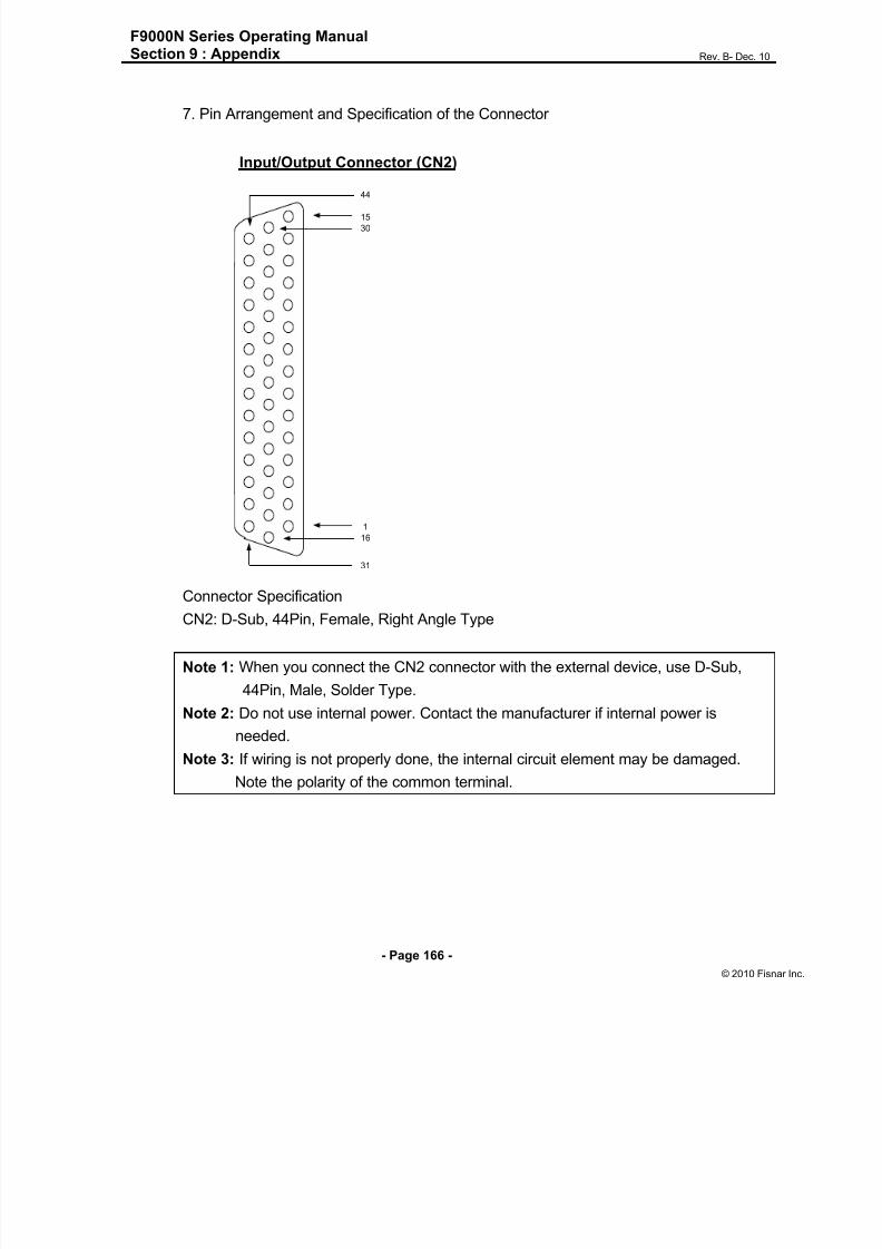
8/13/2019 Manual F9000N (RevB).pdf
http://slidepdf.com/reader/full/manual-f9000n-revbpdf 166/194
F9000N Series Operating ManualSection 9 : Appendix Rev. B- Dec. 10
- Page 166 -
© 2010 Fisna
7. Pin Arrangement and Specification of the Connector
Connector Specification
CN2: D-Sub, 44Pin, Female, Right Angle Type
Note 1: When you connect the CN2 connector with the external device, use D-Sub,
44Pin, Male, Solder Type.
Note 2: Do not use internal power. Contact the manufacturer if internal power is
needed.
Note 3: If wiring is not properly done, the internal circuit element may be damaged.
Note the polarity of the common terminal.
1
16
31
15
30
44
Input/Output Connector (CN2)
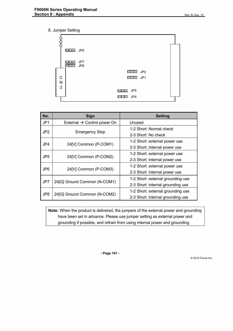
8/13/2019 Manual F9000N (RevB).pdf
http://slidepdf.com/reader/full/manual-f9000n-revbpdf 167/194
F9000N Series Operating ManualSection 9 : Appendix Rev. B- Dec. 10
- Page 167 -
© 2010 Fisna
8. Jumper Setting
Note: When the product is delivered, the jumpers of the external power and grounding
have been set in advance. Please use jumper setting as external power and
grounding if possible, and refrain from using internal power and grounding.
No. Sign Setting
JP1 External Control power On Unused
JP2 Emergency Stop1-2 Short: Normal check
2-3 Short: No check
JP4 24[V] Common (P-COM1)1-2 Short: external power use
2-3 Short: internal power use
JP5 24[V] Common (P-COM2) 1-2 Short: external power use2-3 Short: internal power use
JP6 24[V] Common (P-COM3)1-2 Short: external power use
2-3 Short: internal power use
JP7 24[G] Ground Common (N-COM1)1-2 Short: external grounding use
2-3 Short: internal grounding use
JP8 24[G] Ground Common (N-COM2)1-2 Short: external grounding use
2-3 Short: internal grounding use
C
N
2
JP1
JP2
JP4
JP5
JP6
JP7JP8

8/13/2019 Manual F9000N (RevB).pdf
http://slidepdf.com/reader/full/manual-f9000n-revbpdf 168/194
F9000N Series Operating ManualSection 9 : Appendix Rev. B- Dec. 10
- Page 168 -
© 2010 Fisna
3. App endix C: Equipment (machine) Connect ion
A Separate Harness connecting cable is used to connect the manipulator and controller.
1. Exterior of controller
2. Cables for the F9000N Cartesian coordinate robot
1) Exterior View of the Separate Harness
Power connector
Encoder Connector
Machine connector
Power connector
(Upper: Ch1, Lower: Ch2)
Power connector
(Upper: Ch3, Lower: Ch4)
Encoder connector
(Upper: Ch3, Lower: Ch4)
Encoder connector
(Upper: Ch1, Lower: Ch2)
User I/O Board Connector
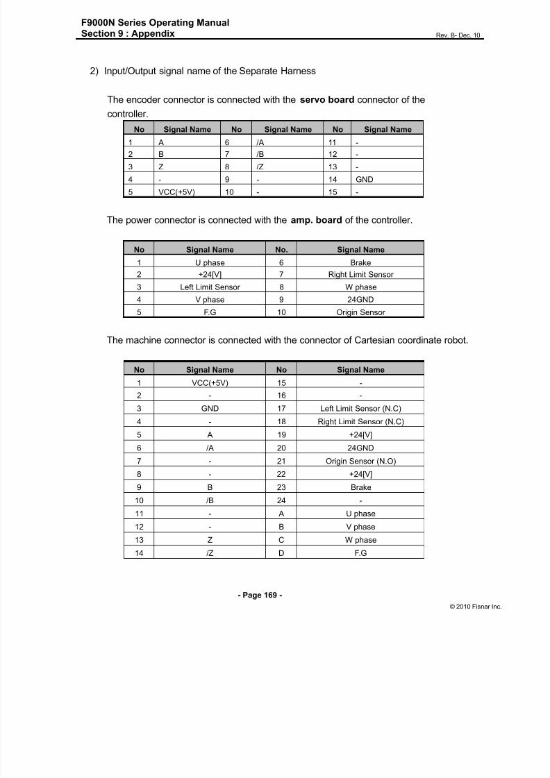
8/13/2019 Manual F9000N (RevB).pdf
http://slidepdf.com/reader/full/manual-f9000n-revbpdf 169/194
F9000N Series Operating ManualSection 9 : Appendix Rev. B- Dec. 10
- Page 169 -
© 2010 Fisna
2) Input/Output signal name of the Separate Harness
The encoder connector is connected with the servo board connector of the
controller.
No Signal Name No Signal Name No Signal Name
1 A 6 /A 11 -
2 B 7 /B 12 -
3 Z 8 /Z 13 -
4 - 9 - 14 GND
5 VCC(+5V) 10 - 15 -
The power connector is connected with the amp. board of the controller.
No Signal Name No. Signal Name
1 U phase 6 Brake
2 +24[V] 7 Right Limit Sensor
3 Left Limit Sensor 8 W phase
4 V phase 9 24GND
5 F.G 10 Origin Sensor
The machine connector is connected with the connector of Cartesian coordinate robot.
No Signal Name No Signal Name
1 VCC(+5V) 15 -
2 - 16 -
3 GND 17 Left Limit Sensor (N.C)
4 - 18 Right Limit Sensor (N.C)
5 A 19 +24[V]
6 /A 20 24GND
7 - 21 Origin Sensor (N.O)
8 - 22 +24[V]
9 B 23 Brake
10 /B 24 -
11 - A U phase
12 - B V phase
13 Z C W phase
14 /Z D F.G

8/13/2019 Manual F9000N (RevB).pdf
http://slidepdf.com/reader/full/manual-f9000n-revbpdf 170/194
F9000N Series Operating ManualSection 9 : Appendix Rev. B- Dec. 10
- Page 170 -
© 2010 Fisna
3) Pin assignment of the connector for the Separate Harness
Power connector Encoder connector
Machine connector
1 2 3
4 5 6 7
8 9 10
1 5
611
1015
1 2 3 4
5 6 7 8 A
B C
D
9 10 11 12
13 14 15 16
17 18 19 20
21 22 23 24
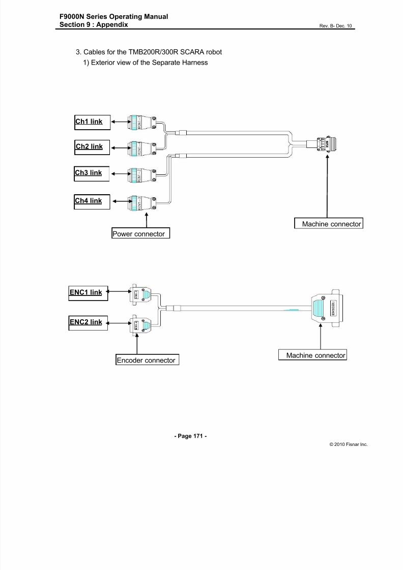
8/13/2019 Manual F9000N (RevB).pdf
http://slidepdf.com/reader/full/manual-f9000n-revbpdf 171/194
F9000N Series Operating ManualSection 9 : Appendix Rev. B- Dec. 10
- Page 171 -
© 2010 Fisna
3. Cables for the TMB200R/300R SCARA robot
1) Exterior view of the Separate Harness
Ch1 link
Ch2 link
Ch3 link
Ch4 link
Power connector
Machine connecto
ENC1 link
ENC2 link
Encoder connector Machine connector

8/13/2019 Manual F9000N (RevB).pdf
http://slidepdf.com/reader/full/manual-f9000n-revbpdf 172/194

8/13/2019 Manual F9000N (RevB).pdf
http://slidepdf.com/reader/full/manual-f9000n-revbpdf 173/194
F9000N Series Operating ManualSection 9 : Appendix Rev. B- Dec. 10
- Page 173 -
© 2010 Fisna
2) Input/Output Signal Name of the Separate Harness
A) Separate harness for the Encoder
Encoder connector (RCN2-1) is connected with the Servo board connector (ENC1).
No Signal Name No Signal Name No Signal Name
1 1_A 6 1_/A 11 1_VCC(+5V)
2 1_B 7 1_/B 12 -
3 1_Z 8 1_/Z 13 -
4 1_Rx 9 1_/Rx 14 -
5 1_PRESET 10 - 15 1_GND
Encoder connector (RCN2-4) is connected with the Servo board connector (ENC2).
No Signal Name No Signal Name No Signal Name
1 4_A 6 4_/A 11 4_VCC(+5V)
2 4_B 7 4_/B 12 -
3 4_Z 8 4_/Z 13 -
4 4_Rx 9 4_/Rx 14 -
5 4_PRESET 10 - 15 4_GND
The machine connector is connected with the ENCODER1 connector.
No Signal Name No Signal Name
1 1_A 17 4_A
2 1_B 16 4_B
3 1_Z 15 4_Z
4 1_Rx 14 4_Rx
9 1_PRESET 18 4_PRESET
5 1_/A 22 4_/A
6 1_/B 21 4_/B
7 1_/Z 20 4_/Z
8 1_/Rx 19 4_/Rx
10 1_VCC(+5V) 24 4_VCC(+5V)
11 1_GND 23 4_GND
25 Shield 25 Shield

8/13/2019 Manual F9000N (RevB).pdf
http://slidepdf.com/reader/full/manual-f9000n-revbpdf 174/194
F9000N Series Operating ManualSection 9 : Appendix Rev. B- Dec. 10
- Page 174 -
© 2010 Fisna
Encoder connector (RCN2-2) is connected to the Servo board connector (ENC3).
No Signal Name No Signal Name No Signal Name
1 2_A 6 2_/A 11 2_VCC(+5V)
2 2_B 7 2_/B 12 -
3 2_Z 8 2_/Z 13 -4 2_Rx 9 2_/Rx 14 -
5 2_PRESET 10 - 15 2_GND
The encoder connector (RCN2-3) is connected with the Servo board connector
(ENC4).
No Signal Name No Signal Name No Signal Name
1 3_A 6 3_/A 11 3_VCC(+5V)
2 3_B 7 3_/B 12 -
3 3_Z 8 3_/Z 13 -
4 3_Rx 9 3_/Rx 14 -
5 3_PRESET 10 - 15 3_GND
The machine connector is connected with the ENCODER2 connector.
No Signal Name No Signal Name
1 2_A 17 3_A
2 2_B 16 3_B
3 2_Z 15 3_Z
4 2_Rx 14 3_Rx
9 2_PRESET 18 3_PRESET
5 2_/A 22 3_/A
6 2_/B 21 3_/B
7 2_/Z 20 3_/Z
8 2/Rx 19 3_/Rx
10 2VCC(+5V) 24 3_VCC(+5V)
11 2GND 23 3_GND
25 Shield 25 Shield

8/13/2019 Manual F9000N (RevB).pdf
http://slidepdf.com/reader/full/manual-f9000n-revbpdf 175/194
F9000N Series Operating ManualSection 9 : Appendix Rev. B- Dec. 10
- Page 175 -
© 2010 Fisna
B) Separate harness for the Power
Power connector (RCN1-1) is connected with the Amp. Board connector (Ch1).
No Signal Name No Signal Name
1 1_U phase 8 1_W phase
4 1_V phase 5 F.G
Power connector (RCN1-4) is connected with the Amp. Board connector (Ch2).
No Signal Name No Signal Name
1 4_U phase 8 4_W phase
4 4_V phase
Power connector (RCN1-2) is connected with the Amp. Board connector (Ch3).
No Signal Name No Signal Name
1 2_U phase 8 2_W phase
4 2_V phase
Power connector (RCN1-3) is connected with the Amp. Board connector (Ch4).
No Signal Name No Signal Name
1 3_U phase 2 +24[V]
4 3_V phase 9 24GND
8 3_W phase 6 Brake
The machine connector is connected with the Motor connector.
No Signal Name No Signal
A 1_U phase E 2_V phase
B 1_V phase G 2_W phase
C 1_W phase F 3_U phase
S F.G J 3_V phase
D 2_U phase L 3_W phase
M +24[V] H 4_U phase
P 24GND K 4_V phase
R Brake N 4_W phase

8/13/2019 Manual F9000N (RevB).pdf
http://slidepdf.com/reader/full/manual-f9000n-revbpdf 176/194
F9000N Series Operating ManualSection 9 : Appendix Rev. B- Dec. 10
- Page 176 -
© 2010 Fisna
C) Separate harness for the User I/O
RCN3-1 is connected with the User I/O board connector (CN2).
No Signal Name No Signal Name
16 +24[V] 43 INPUT 30
12 INPUT 28 44 INPUT 31
28 INPUT 29 15 24GND
RCN3-2 is connected with the User I/O board connector (CN3).
No Signal No Signal Name
26 OUTPUT 24 12 OUTPUT 28
41 OUTPUT 25 28 OUTPUT 29
42 OUTPUT 26 43 OUTPUT 30
27 OUTPUT 27 44 OUTPUT 31
Machine connector is connected with the I/O connector.
No Signal Name No Signal Name
1 +24[V] 3 OUTPUT 25
10 INPUT 28 4 OUTPUT 26
11 INPUT 29 5 OUTPUT 27
12 INPUT 30 6 OUTPUT 28
13 INPUT 31 7 OUTPUT 29
9 24GND 8 OUTPUT 30
2 OUTPUT 24 15 OUTPUT 31

8/13/2019 Manual F9000N (RevB).pdf
http://slidepdf.com/reader/full/manual-f9000n-revbpdf 177/194
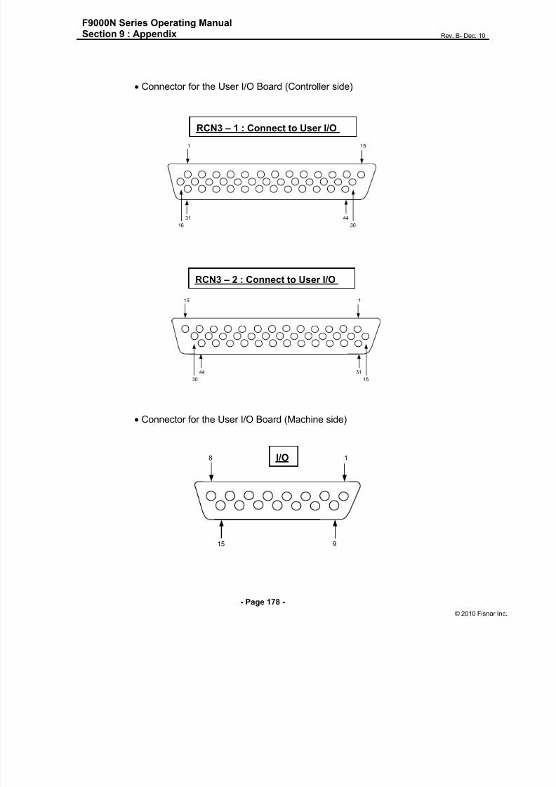
8/13/2019 Manual F9000N (RevB).pdf
http://slidepdf.com/reader/full/manual-f9000n-revbpdf 178/194
F9000N Series Operating ManualSection 9 : Appendix Rev. B- Dec. 10
- Page 178 -
© 2010 Fisna
Connector for the User I/O Board (Controller side)
Connector for the User I/O Board (Machine side)
151
31
3016
44
RCN3 – 1 : Connect to User I/O
CN
115
44
1630
31
18
15 9
I/O
RCN3 – 2 : Connect to User I/O
CN3

8/13/2019 Manual F9000N (RevB).pdf
http://slidepdf.com/reader/full/manual-f9000n-revbpdf 179/194

8/13/2019 Manual F9000N (RevB).pdf
http://slidepdf.com/reader/full/manual-f9000n-revbpdf 180/194
F9000N Series Operating ManualSection 9 : Appendix Rev. B- Dec. 10
- Page 180 -
© 2010 Fisna
4.2. F9304N

8/13/2019 Manual F9000N (RevB).pdf
http://slidepdf.com/reader/full/manual-f9000n-revbpdf 181/194

8/13/2019 Manual F9000N (RevB).pdf
http://slidepdf.com/reader/full/manual-f9000n-revbpdf 182/194
F9000N Series Operating ManualSection 9 : Appendix Rev. B- Dec. 10
- Page 182 -
© 2010 Fisna
4.4. F9604N

8/13/2019 Manual F9000N (RevB).pdf
http://slidepdf.com/reader/full/manual-f9000n-revbpdf 183/194

8/13/2019 Manual F9000N (RevB).pdf
http://slidepdf.com/reader/full/manual-f9000n-revbpdf 184/194
F9000N Series Operating ManualSection 9 : Appendix Rev. B- Dec. 10
- Page 184 -
© 2010 Fisna
4.6. F9804N
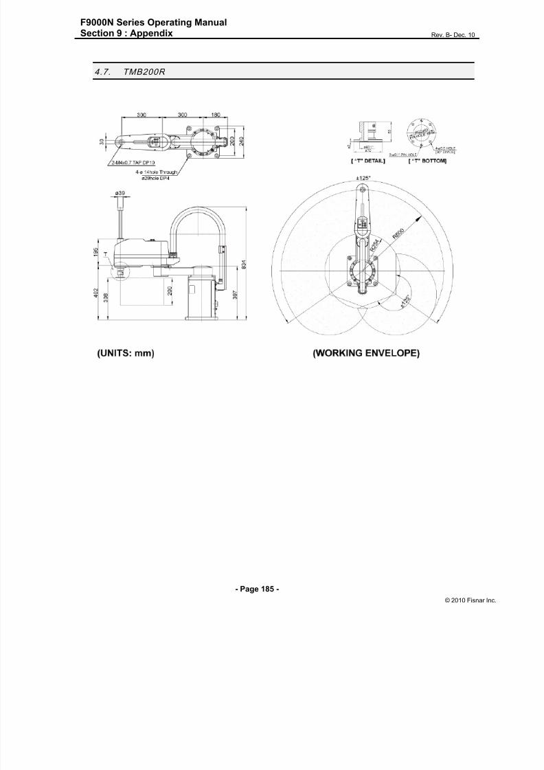
8/13/2019 Manual F9000N (RevB).pdf
http://slidepdf.com/reader/full/manual-f9000n-revbpdf 185/194
F9000N Series Operating ManualSection 9 : Appendix Rev. B- Dec. 10
- Page 185 -
© 2010 Fisna
4.7. TMB200R

8/13/2019 Manual F9000N (RevB).pdf
http://slidepdf.com/reader/full/manual-f9000n-revbpdf 186/194

8/13/2019 Manual F9000N (RevB).pdf
http://slidepdf.com/reader/full/manual-f9000n-revbpdf 187/194
F9000N Series Operating ManualSection 9 : Appendix Rev. B- Dec. 10
- Page 187 -
© 2010 Fisna
5. Append ix E : Table Dimens ions
(Optional)
5.1. F9300N/F9304N

8/13/2019 Manual F9000N (RevB).pdf
http://slidepdf.com/reader/full/manual-f9000n-revbpdf 188/194
F9000N Series Operating ManualSection 9 : Appendix Rev. B- Dec. 10
- Page 188 -
© 2010 Fisna
5.2. F9600N/F9604N

8/13/2019 Manual F9000N (RevB).pdf
http://slidepdf.com/reader/full/manual-f9000n-revbpdf 189/194

8/13/2019 Manual F9000N (RevB).pdf
http://slidepdf.com/reader/full/manual-f9000n-revbpdf 190/194
F9000N Series Operating ManualSection 9 : Appendix Rev. B- Dec. 10
- Page 190 -
© 2010 Fisna
6. App endix F: Coordinates (axes) of robots
6.1. Manipu lator of F9000N Series
From Zero (origin) point at the Manipulator base, X coordinate is designated far forward
and backward directions, Y coordinate for right and left directions, Z coordinate for upward
and downward directions and W coordinates for clockwise and counterclockwise rotations.

8/13/2019 Manual F9000N (RevB).pdf
http://slidepdf.com/reader/full/manual-f9000n-revbpdf 191/194
F9000N Series Operating ManualSection 9 : Appendix Rev. B- Dec. 10
- Page 191 -
© 2010 Fisna
6.2. Manipu lator of TMB200R / TMB300R Series
6.2.1. Join t Coor dinates
Joint coordinate indicate rotation angle for each axis. Axis 1,2, and 4 coordinates aredesignated in degrees and axis 3 coordinate is designed in mm. During operation, the
rotation speed of each axis is indicated as a percentage from its maximum motor speed.
JT
JT
JT
JT
(1 axis)
(2 axis)
(3 axis)
4 axis
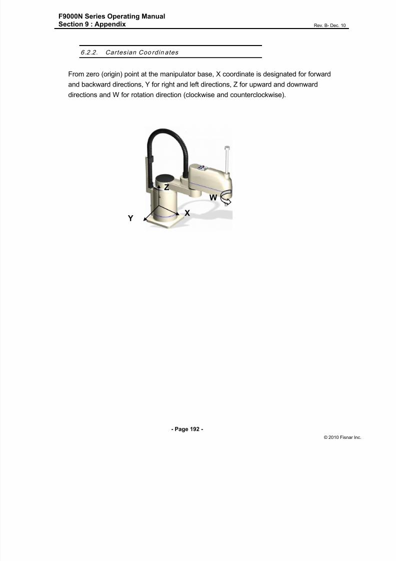
8/13/2019 Manual F9000N (RevB).pdf
http://slidepdf.com/reader/full/manual-f9000n-revbpdf 192/194
F9000N Series Operating ManualSection 9 : Appendix Rev. B- Dec. 10
- Page 192 -
© 2010 Fisna
6.2.2. Cartesian Coo rdin ates
From zero (origin) point at the manipulator base, X coordinate is designated for forward
and backward directions, Y for right and left directions, Z for upward and downwarddirections and W for rotation direction (clockwise and counterclockwise).
X Y
Z
W

8/13/2019 Manual F9000N (RevB).pdf
http://slidepdf.com/reader/full/manual-f9000n-revbpdf 193/194

8/13/2019 Manual F9000N (RevB).pdf
http://slidepdf.com/reader/full/manual-f9000n-revbpdf 194/194