Embed Size (px)
Citation preview
MANUAL P/N FSG–MNL–00183 Revision B
COPYRIGHT © 2018 BY HALE PRODUCTS, INC. ALL RIGHTS RESERVED
OPERATION INSTALLATION MAINTENANCE
MANUAL
FOR HALE FLEX SERIES
SINGLE STAGE BOOSTER PUMPS
BY HALE PRODUCTS, INC.
A Unit of IDEX Corporation 607 NW 27th Ave, Ocala, FL 34475
(800) 533.3569 (800) 520.3473 (FAX) www.haleproducts.com

i
TABLE OF CONTENTS Section Title Page
1. SAFETY ............................................................................................................................................. 1
1.1. Safety Headings ........................................................................................................................ 1
1.2. Training ..................................................................................................................................... 1
1.3. Safety Summary ....................................................................................................................... 1
2. GENERAL INSTRUCTIONS ............................................................................................................... 5
2.1. Overview .................................................................................................................................... 5
2.2. Pump Specifications and Numbering ...................................................................................... 5
2.2.1 Optional Pump Panel Identification Plates ....................................................................... 5
2.2.2 Identification Plate ............................................................................................................. 6
3. TRANSPORT AND STORAGE ........................................................................................................... 7
3.1. Shipping, Movement, And Installation Preparations .............................................................. 7
3.2. Pump Gearbox Shipped Without Fluid .................................................................................... 7
3.3. Storage ...................................................................................................................................... 7
4. PUMP OVERVIEW ............................................................................................................................ 9
5. INSTALLATION .............................................................................................................................. 11
5.1. Warnings And Cautions ......................................................................................................... 11
5.2. Risk Assessment ................................................................................................................... 11
5.3. Special Tools .......................................................................................................................... 11
5.4. Mounting A Hale Booster Pump ........................................................................................... 11
5.4.1 Hardware Requirements ................................................................................................ 13
5.4.1.1 Mounting Hardware .................................................................................................. 13
5.4.1.2 Thread Lock, Bonding, Or Sealant Compound ....................................................... 14
5.4.1.3 Driveshaft Hardware ................................................................................................ 14
5.4.2 Inlet And Discharge Connections ................................................................................... 14
5.4.3 Booster Pump Drains ...................................................................................................... 14
5.4.4 Priming Connections ....................................................................................................... 14
6. COMMISSIONING, STARTUP, OPERATION, AND SHUTDOWN .................................................... 15
6.1. Installation Verification ......................................................................................................... 15
6.2. Performance Verification ...................................................................................................... 15
6.3. Initial Startup ......................................................................................................................... 15
6.4. Draft Operation Notes ........................................................................................................... 17
6.5. Hydrant Or Relay Operation .................................................................................................. 18
ii
TABLE OF CONTENTS – CONTINUED Section Title Page
6.6. Pump Cavitation .................................................................................................................... 18
6.6.1 Discharge Pressure Cavitation Warning Signs .............................................................. 18
6.6.2 Vacuum Compound Gauge Warning Signs.................................................................... 18
6.6.3 General Considerations to Prevent Cavitation .............................................................. 19
6.7. Post Operation Notes ............................................................................................................ 19
7. PREVENTIVE MAINTENANCE ....................................................................................................... 21
7.1. Preventive Maintenance Plan and Schedule ....................................................................... 21
7.2. Maintenance Log ................................................................................................................... 21
7.3. Extreme Conditions Maintenance Guidelines ..................................................................... 21
7.3.1 Freezing Weather ............................................................................................................ 22
7.3.2 Contaminated Water ....................................................................................................... 22
7.4. Booster Pump Preventive Maintenance Procedures .......................................................... 22
7.4.1 After Each Use ................................................................................................................. 22
7.4.2 Quarterly Maintenance (every three months) ............................................................... 22
7.4.2.1 Check Gearbox Fluid Level ...................................................................................... 22
7.4.2.2 Perform Vacuum Test ............................................................................................... 23
7.4.3 Annual Pump Maintenance ............................................................................................ 23
7.4.3.1 Performance Testing ................................................................................................ 23
7.4.3.1.1 Test Procedure ................................................................................................... 23
7.4.4 Triennial Pump Maintenance ......................................................................................... 24
7.4.4.1 Fluid Change Procedure ........................................................................................... 24
7.4.4.1.1 Recommended Gearbox Lubricants ................................................................. 26
8. SYMPTOMS, CAUSES, AND REMEDIES ....................................................................................... 27
8.1. Loss Of Suction Fault Flow Chart .......................................................................................... 27
8.1.1 Loss Of Suction Symptoms, Causes, And Remedies .................................................... 29
8.2. Cavitation Fault Flow Chart ................................................................................................... 30
8.2.1 Cavitation Symptoms, Causes, And Remedies ............................................................. 31
APPENDIX A. MANUFACTURER'S INFORMATION ....................................................................... A–1
MANUFACTURER'S INFORMATION ................................................................................................... A–1
WARRANTY ........................................................................................................................................ A–1
iii
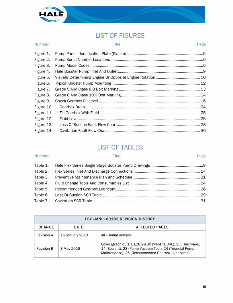
LIST OF FIGURES Number Title Page
Figure 1. Pump Panel Identification Plate (Placard) ....................................................................... 5 Figure 2. Pump Serial Number Locations ........................................................................................ 6 Figure 3. Pump Model Codes ........................................................................................................... 6 Figure 4. Hale Booster Pump Inlet And Outlet ................................................................................. 9 Figure 5. Visually Determining Engine Or Opposite Engine Rotation .......................................... 10 Figure 6. Typical Booster Pump Mounting .................................................................................... 12 Figure 7. Grade 5 And Class 8.8 Bolt Marking ............................................................................. 13 Figure 8. Grade 8 And Class 10.9 Bolt Marking ........................................................................... 14 Figure 9. Check Gearbox Oil Level ................................................................................................. 16 Figure 10. Gearbox Drain ............................................................................................................. 24 Figure 11. Fill Gearbox With Fluid ................................................................................................ 25 Figure 12. Fluid Level ................................................................................................................... 25 Figure 13. Loss Of Suction Fault Flow Chart ............................................................................... 28 Figure 14. Cavitation Fault Flow Chart ........................................................................................ 30
LIST OF TABLES Number Title Page
Table 1. Hale Flex Series Single Stage Booster Pump Drawings .................................................. 9 Table 2. Flex Series Inlet And Discharge Connections ............................................................... 14 Table 3. Preventive Maintenance Plan and Schedule ................................................................ 21 Table 4. Fluid Change Tools And Consumables List ................................................................... 24 Table 5. Recommended Gearbox Lubricant ................................................................................ 26 Table 6. Loss Of Suction SCR Table ............................................................................................. 29 Table 7. Cavitation SCR Table ...................................................................................................... 31
FSG–MNL–00183 REVISION HISTORY
CHANGE DATE AFFECTED PAGES
Revision A 15 January 2019 All – Initial Release
Revision B 8 May 2019 Cover (graphic), 1,10,28,29,30 (website URL), 13 (Hardware), 14 (Sealant), 23 (Pump Vacuum Test), 24 (Triennial Pump Maintenance), 26 (Recommended Gearbox Lubricants)
iv
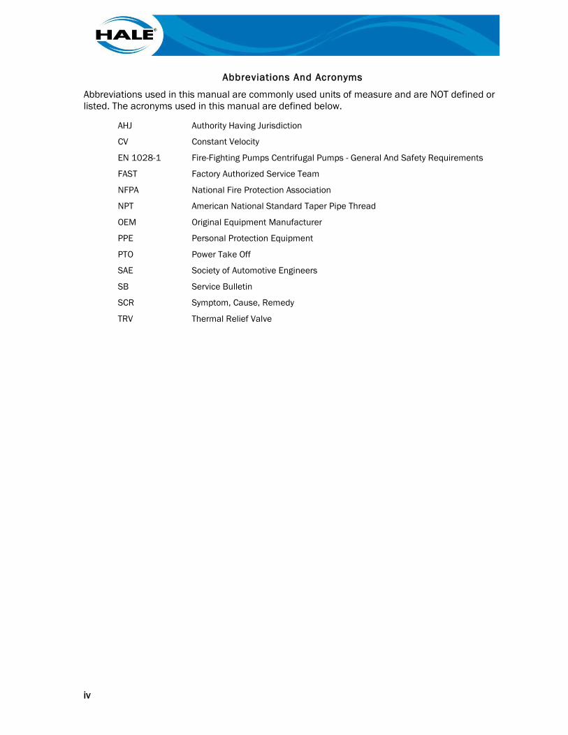
Abbreviations And Acronyms
Abbreviations used in this manual are commonly used units of measure and are NOT defined or listed. The acronyms used in this manual are defined below.
AHJ Authority Having Jurisdiction
CV Constant Velocity
EN 1028-1 Fire-Fighting Pumps Centrifugal Pumps - General And Safety Requirements
FAST Factory Authorized Service Team
NFPA National Fire Protection Association
NPT American National Standard Taper Pipe Thread
OEM Original Equipment Manufacturer
PPE Personal Protection Equipment
PTO Power Take Off
SAE Society of Automotive Engineers
SB Service Bulletin
SCR Symptom, Cause, Remedy
TRV Thermal Relief Valve
1
1. SAFETY Read and comply with all safety items in this manual before operating the pump. Only fully trained personnel may operate or maintain pump.
If EN 1028 is applicable to the user, the end user must maintain the equipment in an operational condition, as per regulation 5 in the Provision and Use of Work Equipment Regulations 1998.
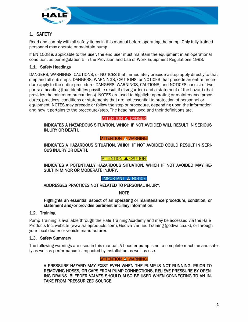
1.1. Safety Headings
DANGERS, WARNINGS, CAUTIONS, or NOTICES that immediately precede a step apply directly to that step and all sub steps. DANGERS, WARNINGS, CAUTIONS, or NOTICES that precede an entire proce-dure apply to the entire procedure. DANGERS, WARNINGS, CAUTIONS, and NOTICES consist of two parts: a heading (that identifies possible result if disregarded) and a statement of the hazard (that provides the minimum precautions). NOTES are used to highlight operating or maintenance proce-dures, practices, conditions or statements that are not essential to protection of personnel or equipment. NOTES may precede or follow the step or procedure, depending upon the information and how it pertains to the procedure/step. The headings used and their definitions are.
INDICATES A HAZARDOUS SITUATION, WHICH IF NOT AVOIDED WILL RESULT IN SERIOUS INJURY OR DEATH.
INDICATES A HAZARDOUS SITUATION, WHICH IF NOT AVOIDED COULD RESULT IN SERI-OUS INJURY OR DEATH.
INDICATES A POTENTIALLY HAZARDOUS SITUATION, WHICH IF NOT AVOIDED MAY RE-SULT IN MINOR OR MODERATE INJURY.
ADDRESSES PRACTICES NOT RELATED TO PERSONAL INJURY.
NOTE
Highlights an essential aspect of an operating or maintenance procedure, condition, or statement and/or provides pertinent ancillary information.
1.2. Training
Pump Training is available through the Hale Training Academy and may be accessed via the Hale Products Inc. website (www.haleproducts.com), Godiva √erified Training (godiva.co.uk), or through your local dealer or vehicle manufacturer.
1.3. Safety Summary
The following warnings are used in this manual. A booster pump is not a complete machine and safe-ty as well as performance is impacted by installation as well as use.
A PRESSURE HAZARD MAY EXIST EVEN WHEN THE PUMP IS NOT RUNNING. PRIOR TO REMOVING HOSES, OR CAPS FROM PUMP CONNECTIONS, RELIEVE PRESSURE BY OPEN-ING DRAINS. BLEEDER VALVES SHOULD ALSO BE USED WHEN CONNECTING TO AN IN-TAKE FROM PRESSURIZED SOURCE.
2
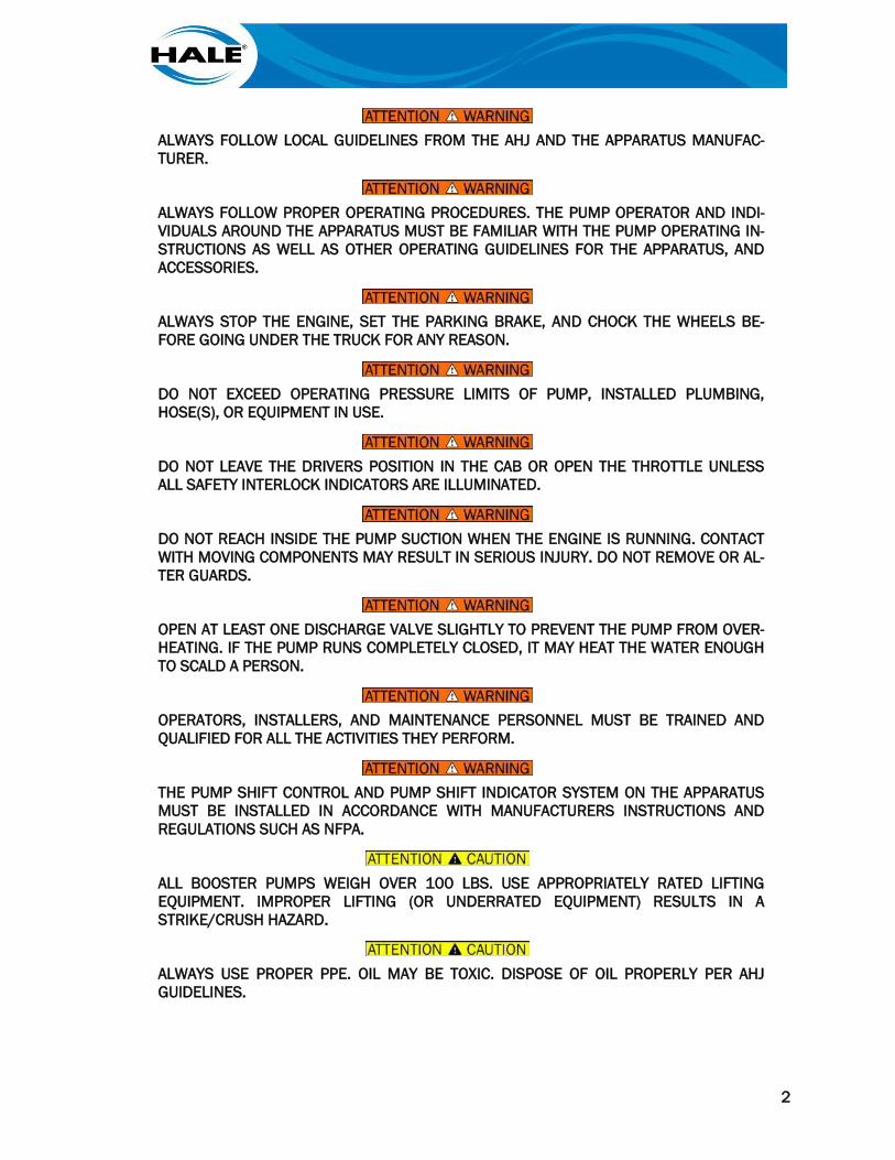
ALWAYS FOLLOW LOCAL GUIDELINES FROM THE AHJ AND THE APPARATUS MANUFAC-TURER.
ALWAYS FOLLOW PROPER OPERATING PROCEDURES. THE PUMP OPERATOR AND INDI-VIDUALS AROUND THE APPARATUS MUST BE FAMILIAR WITH THE PUMP OPERATING IN-STRUCTIONS AS WELL AS OTHER OPERATING GUIDELINES FOR THE APPARATUS, AND ACCESSORIES.
ALWAYS STOP THE ENGINE, SET THE PARKING BRAKE, AND CHOCK THE WHEELS BE-FORE GOING UNDER THE TRUCK FOR ANY REASON.
DO NOT EXCEED OPERATING PRESSURE LIMITS OF PUMP, INSTALLED PLUMBING, HOSE(S), OR EQUIPMENT IN USE.
DO NOT LEAVE THE DRIVERS POSITION IN THE CAB OR OPEN THE THROTTLE UNLESS ALL SAFETY INTERLOCK INDICATORS ARE ILLUMINATED.
DO NOT REACH INSIDE THE PUMP SUCTION WHEN THE ENGINE IS RUNNING. CONTACT WITH MOVING COMPONENTS MAY RESULT IN SERIOUS INJURY. DO NOT REMOVE OR AL-TER GUARDS.
OPEN AT LEAST ONE DISCHARGE VALVE SLIGHTLY TO PREVENT THE PUMP FROM OVER-HEATING. IF THE PUMP RUNS COMPLETELY CLOSED, IT MAY HEAT THE WATER ENOUGH TO SCALD A PERSON.
OPERATORS, INSTALLERS, AND MAINTENANCE PERSONNEL MUST BE TRAINED AND QUALIFIED FOR ALL THE ACTIVITIES THEY PERFORM.
THE PUMP SHIFT CONTROL AND PUMP SHIFT INDICATOR SYSTEM ON THE APPARATUS MUST BE INSTALLED IN ACCORDANCE WITH MANUFACTURERS INSTRUCTIONS AND REGULATIONS SUCH AS NFPA.
ALL BOOSTER PUMPS WEIGH OVER 100 LBS. USE APPROPRIATELY RATED LIFTING EQUIPMENT. IMPROPER LIFTING (OR UNDERRATED EQUIPMENT) RESULTS IN A STRIKE/CRUSH HAZARD.
ALWAYS USE PROPER PPE. OIL MAY BE TOXIC. DISPOSE OF OIL PROPERLY PER AHJ GUIDELINES.
3
DO NOT REPLACE FASTENERS WITH OTHER THAN HALE PART NUMBERS PROVIDED.
FOLLOW DEPARTMENT PROCEDURES TO SET WHEEL CHOCKS WHEN PUMPING.
USE PPE TO PROTECT HANDS AND FINGERS FROM SHARP EDGES. THE EDGES OF THE BLADES ON THE INDUCER OR IMPELLER MAY BE SHARP.
ALLOWING INTAKE PRESSURES TO FALL BELOW ESTABLISHED LIMITS MAY RESULT IN DAMAGE TO THE WATER SUPPLY PIPING WHEN PUMPING FROM HYDRANT.
BEFORE LAY OUT AND INSTALLATION OF THE DRIVELINE, CONSULT APPARATUS AND/OR DRIVELINE COMPONENT MANUFACTURER FOR GUIDANCE AND REFER TO HALE SB90 FOR ALIGNMENT OF DRIVESHAFT AND PUMP DRIVE.
CHECK MAGNETIC DRAIN PLUG FOR DEBRIS. IF SIGNIFICANT METAL FRAGMENTS ARE PRESENT, REPORT CONDITION TO AHJ SO SERVICE CAN BE PERFORMED.
DO NOT ALLOW A WHIRLPOOL AT THE SUCTION STRAINER WHEN DRAFTING.
DO NOT EXCEED 15 DEGREE ANGLE IN OPERATION OF PUMP SYSTEM.
DO NOT EXCEED POWER TRAIN LIMITS WHEN INSTALLING A PUMP. A MEANS TO CON-TROL THE ENGINE OUTPUT WHEN PTO IS ENGAGED SHOULD BE CONSIDERED.
DO NOT OPERATE PUMP WITHOUT SUCTION STRAINER IN PLACE.
DO NOT OPERATE PUMP WITHOUT WATER OR WITHOUT DISCHARGING WATER FOR EX-TENDED TIME, IT MAY OVERHEAT CAUSING DAMAGE.
DO NOT RUN ENGINE HIGHER THAN 1200 RPM DURING PRIMING.
DO NOT RUN THE PRIMER FOR MORE THAN 45 SECONDS. IF PRIME IS NOT ACHIEVED IN 30 - 45 SECONDS, STOP AND LOOK FOR AIR LEAKS OR BLOCKED SUCTION HOSE.
DO NOT USE THE RED IDLE BUTTON UNLESS AN EMERGENCY AS DEFINED BY THE AHJ EXISTS.
4
FAILURE TO INSTALL THE ENGINE SPEED INTERLOCK SYSTEM PROPERLY MAY RESULT IN PTO DAMAGE.
FOLLOW PTO AND VEHICLE MANUFACTURER PTO INSTRUCTIONS.
HALE PUMPS ARE SHIPPED WITHOUT OIL. FILL GEARBOX WITH FLUID LISTED IN TABLE 5 BEFORE OPERATION.
IF THE DISCHARGE PRESSURE DOES NOT INCREASE, AND INTAKE GAUGE READING DOES NOT FALL BELOW ZERO (0), OR THE PRIMING PUMP DOES NOT DISCHARGE WA-TER TO THE GROUND WITHIN 30 SECONDS, STOP THE PUMP AND CHECK FOR AIR LEAKS.
OPEN AT LEAST ONE DISCHARGE VALVE SLIGHTLY TO PREVENT THE PUMP FROM OVER-HEATING. OVERHEATING CAN DAMAGE THE PUMP SEAL, AND OTHER PUMP PARTS.
PUMP ASSEMBLY HAS BOTH METRIC AND SAE HARDWARE.
PUMP DISCHARGE PRESSURE SHOULD INCREASE WITH ENGINE SPEED WHEN OPENING THROTTLE. IF ENGINE SPEED INCREASES WITHOUT INCREASE IN PRESSURE, THE PUMP MAY BE CAVITATING.
5
2. GENERAL INSTRUCTIONS This manual covers the Hale Flex Series of single stage booster pumps and provides basic infor-mation on Hale AP, CBP, MBP, or RSD Flex Series of booster pumps when local procedures do NOT exist. Basics of operation, installation verification, and maintenance are covered.
Additional information is available in FSG–MNL–00184, Technical Manual For Hale Single Stage Booster Pumps. This manual and additional information such as pump curves and rating charts can be found on the flash drive provided with the pump or on the Hale website (www.haleproducts.com).
ALWAYS FOLLOW LOCAL GUIDELINES FROM THE AHJ AND THE APPARATUS MANUFAC-TURER.
2.1. Overview
This manual ONLY covers the Flex Series of single stage booster pumps.
2.2. Pump Specifications and Numbering
Each pump has a unique serial number that can be found in multiple locations. Model numbers de-fine major pump features.
For detailed booster pump specifications, refer to the Hale Products website (www.hale prod-ucts.com). Hale Products Inc. policy is one of continuous development. Hale therefore reserves the right to amend specifications without notice or obligation.
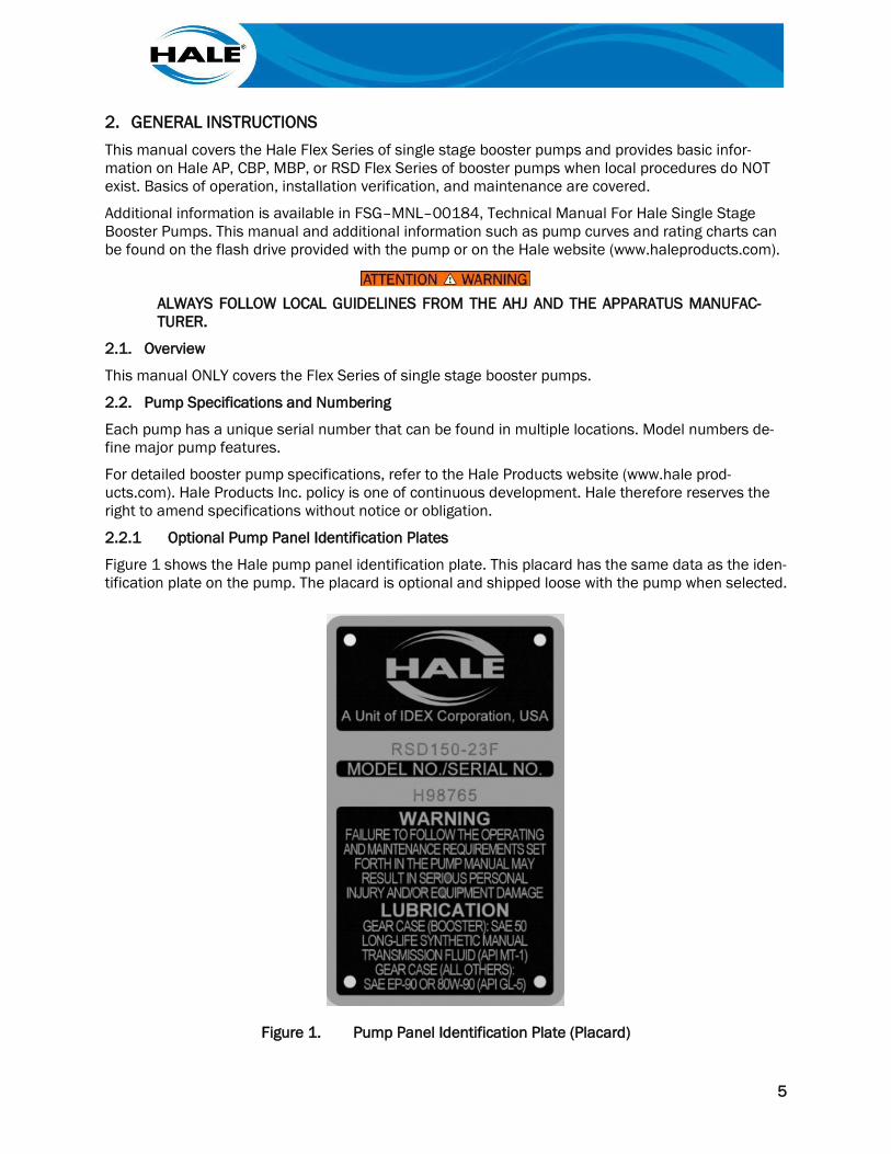
2.2.1 Optional Pump Panel Identification Plates
Figure 1 shows the Hale pump panel identification plate. This placard has the same data as the iden-tification plate on the pump. The placard is optional and shipped loose with the pump when selected.
Figure 1. Pump Panel Identification Plate (Placard)
6
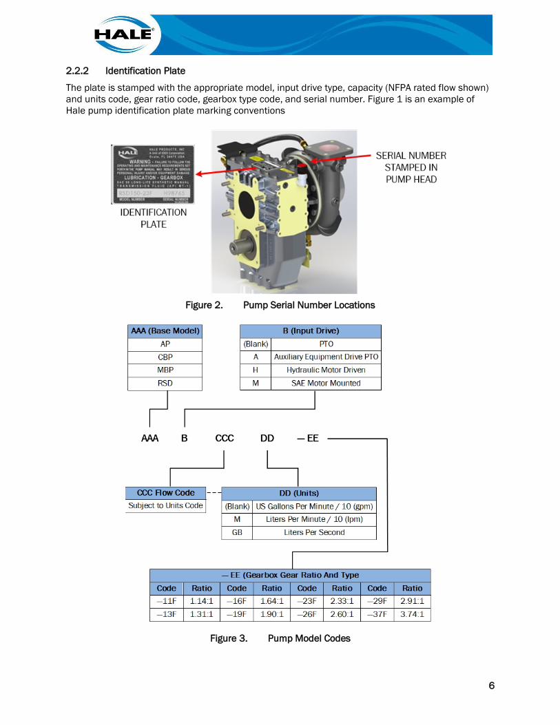
2.2.2 Identification Plate
The plate is stamped with the appropriate model, input drive type, capacity (NFPA rated flow shown) and units code, gear ratio code, gearbox type code, and serial number. Figure 1 is an example of Hale pump identification plate marking conventions
Figure 2. Pump Serial Number Locations
Figure 3. Pump Model Codes
7
3. TRANSPORT AND STORAGE Ship, move, and store a Hale Flex booster pump according to the information herein.
3.1. Shipping, Movement, And Installation Preparations
Hale Flex booster pumps use packaging suitable for shipping and indoor storage. Never stack pumps on top of one another.
Upon receipt, inspect the packaging and pump. If any damage has occurred, take clear detailed pic-tures, and file a claim with the carrier. Contact Hale Customer Support immediately (hale [email protected]).
3.2. Pump Gearbox Shipped Without Fluid
HALE FLEX SERIES PUMPS ARE SHIPPED WITHOUT GEAR OIL. FILL THE GEARBOX WITH MANUAL TRANSMISSION FLUID SPECIFIED IN TABLE 5 BEFORE OPERATING.
Fill the gearbox to the proper level with the fluid listed in paragraph 7.4.4.1.1, Recommended Gear-box Lubricants. See paragraph 7.4.4.1, for instructions to fill the gearbox with fluid.
3.3. Storage
Hale Flex Series pumps should be stored indoors in a protected environment before installation. If the pump needs to be stored for more than six months, see Hale Service Bulletin SB150 on the Hale website.
8
THIS PAGE INTENTIONALLY BLANK.
9
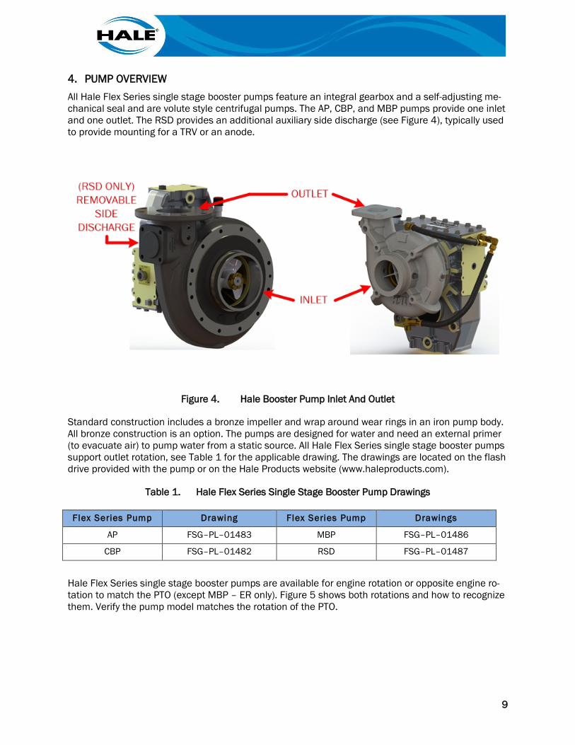
4. PUMP OVERVIEW All Hale Flex Series single stage booster pumps feature an integral gearbox and a self-adjusting me-chanical seal and are volute style centrifugal pumps. The AP, CBP, and MBP pumps provide one inlet and one outlet. The RSD provides an additional auxiliary side discharge (see Figure 4), typically used to provide mounting for a TRV or an anode.
Figure 4. Hale Booster Pump Inlet And Outlet
Standard construction includes a bronze impeller and wrap around wear rings in an iron pump body. All bronze construction is an option. The pumps are designed for water and need an external primer (to evacuate air) to pump water from a static source. All Hale Flex Series single stage booster pumps support outlet rotation, see Table 1 for the applicable drawing. The drawings are located on the flash drive provided with the pump or on the Hale Products website (www.haleproducts.com).
Table 1. Hale Flex Series Single Stage Booster Pump Drawings
Flex Series Pump Drawing Flex Series Pump Drawings
AP FSG–PL–01483 MBP FSG–PL–01486
CBP FSG–PL–01482 RSD FSG–PL–01487
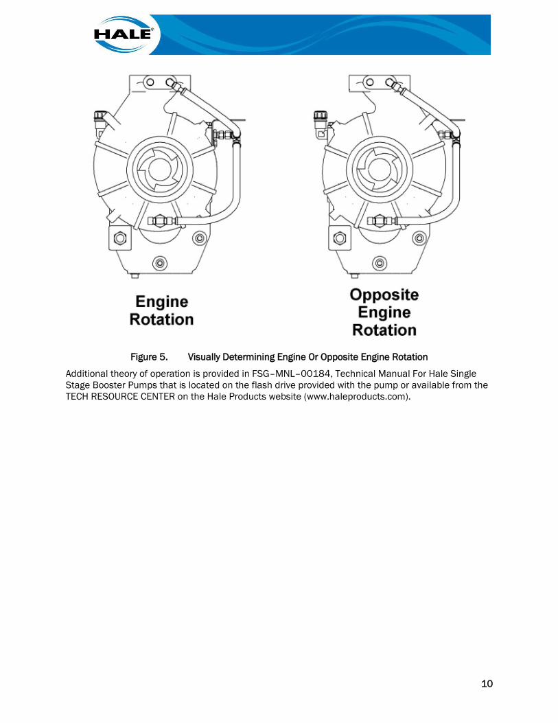
Hale Flex Series single stage booster pumps are available for engine rotation or opposite engine ro-tation to match the PTO (except MBP – ER only). Figure 5 shows both rotations and how to recognize them. Verify the pump model matches the rotation of the PTO.
10
Figure 5. Visually Determining Engine Or Opposite Engine Rotation
Additional theory of operation is provided in FSG–MNL–00184, Technical Manual For Hale Single Stage Booster Pumps that is located on the flash drive provided with the pump or available from the TECH RESOURCE CENTER on the Hale Products website (www.haleproducts.com).
11
5. INSTALLATION This section provides basic information for the installation of Hale booster pumps. Installation per-sonnel should be qualified in pump and plumbing installation and vehicle manufacture.
5.1. Warnings And Cautions
Before attempting to install the pump, read all of the following safety precautions and follow them carefully.
THE PUMP SHIFT CONTROL AND PUMP SHIFT INDICATOR SYSTEM ON THE APPARATUS MUST BE INSTALLED IN ACCORDANCE WITH MANUFACTURERS INSTRUCTIONS AND REGULATIONS SUCH AS NFPA.
BEFORE LAY OUT AND INSTALLATION OF THE DRIVELINE, CONSULT APPARATUS AND/OR DRIVELINE COMPONENT MANUFACTURER FOR GUIDANCE AND REFER TO HALE SB90 FOR ALIGNMENT OF DRIVESHAFT AND PUMP DRIVE.
HALE PUMPS ARE SHIPPED WITHOUT OIL. FILL GEARBOX WITH FLUID LISTED IN TABLE 5 BEFORE OPERATION. FAILURE TO PROPERLY FILL GEARBOX WILL RESULT IN DAMAGE AND VOID WARRANTY.
5.2. Risk Assessment
When EN 1028 applies, the pump installer shall develop and deliver a method statement and risk assessment of operations when installing a Hale booster pump on firefighting apparatus.
5.3. Special Tools
Observe all torque requirements and see FSG–MNL–00184, Technical Manual For Hale Single Stage Booster Pumps for additional information. When conducting testing/verifications for installation pur-poses, bearings temperatures can be checked using an infrared thermometer.
5.4. Mounting A Hale Booster Pump
A PRESSURE HAZARD MAY EXIST EVEN WHEN THE PUMP IS NOT RUNNING. PRIOR TO REMOVING HOSES, OR CAPS FROM PUMP CONNECTIONS, RELIEVE PRESSURE BY OPEN-ING DRAINS. BLEEDER VALVES SHOULD ALSO BE USED WHEN CONNECTING TO AN IN-TAKE FROM PRESSURIZED SOURCE.
ALWAYS STOP THE ENGINE, SET THE PARKING BRAKE, AND CHOCK THE WHEELS BE-FORE GOING UNDER THE TRUCK FOR ANY REASON.
OPEN AT LEAST ONE DISCHARGE VALVE SLIGHTLY TO PREVENT THE PUMP FROM OVER-HEATING. IF THE PUMP RUNS COMPLETELY CLOSED, IT MAY HEAT THE WATER ENOUGH TO SCALD A PERSON.
12
THE PUMP SHIFT CONTROL AND PUMP SHIFT INDICATOR SYSTEM ON THE APPARATUS MUST BE INSTALLED IN ACCORDANCE WITH MANUFACTURERS INSTRUCTIONS AND REGULATIONS SUCH AS NFPA.
BEFORE LAY OUT AND INSTALLATION OF THE DRIVELINE, CONSULT APPARATUS AND/OR DRIVELINE COMPONENT MANUFACTURER FOR GUIDANCE AND REFER TO HALE SB90 FOR ALIGNMENT OF DRIVESHAFT AND PUMP DRIVE.
DO NOT EXCEEDING POWER TRAIN LIMITS WHEN INSTALLING A PUMP. A MEANS TO CONTROL THE ENGINE OUTPUT WHEN PTO IS ENGAGED SHOULD BE CONSIDERED.
FAILURE TO INSTALL THE ENGINE SPEED INTERLOCK SYSTEM PROPERLY MAY RESULT IN PTO DAMAGE.
HALE PUMPS ARE SHIPPED WITHOUT OIL. FILL GEARBOX WITH FLUID LISTED IN TABLE 5 BEFORE OPERATION.
OPEN AT LEAST ONE DISCHARGE VALVE SLIGHTLY TO PREVENT THE PUMP FROM OVER-HEATING. OVERHEATING CAN DAMAGE THE PUMP SEAL, AND OTHER PUMP PARTS.
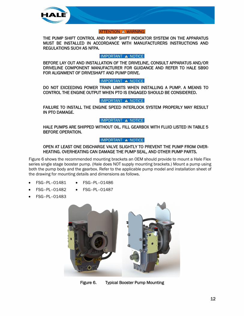
Figure 6 shows the recommended mounting brackets an OEM should provide to mount a Hale Flex series single stage booster pump. (Hale does NOT supply mounting brackets.) Mount a pump using both the pump body and the gearbox. Refer to the applicable pump model and installation sheet of the drawing for mounting details and dimensions as follows.
• FSG–PL–01481 • FSG–PL–01486 • FSG–PL–01482 • FSG–PL–01487 • FSG–PL–01483
Figure 6. Typical Booster Pump Mounting
13
Design the installation with consideration NOT to transmit loads or twisting moments (AKA angular mass or rotational inertia) to (or through) the pump assembly from the apparatus (chassis, frame, bodywork, or suction and discharge piping connections). In addition, DO NOT USE THE MOUNTING HARDWARE to eliminate voids between the bracket(s) and the pump body or gearbox mounting fac-es. If the bracket(s) do not align with the pump/gearbox machined surfaces, reposition the bracket(s) (or use shims/spacers) to ensure the mounting does NOT twist the pump/gearbox.
Attach the OEM provided primary rigid support bracket to the pump body. For an AP, CBP, or RSD use a minimum of three (3) pump body-mounting bosses (CBP and AP) or studs (RSD). For an MBP use a minimum of four (4) pump body-mounting bosses. The pump body-mounting bosses require SAE grade 8 (or better) fasteners to attachment to the bracket(s) (The fasteners are NOT supplied by Hale.)
Attach an OEM provided secondary support bracket to the gearbox using a minimum of three (3) gearbox metric mounting studs. (The drive side of the gearbox provides ten (10) M10–1.5 threaded holes.) Hale supplies four (4) M10 studs, flat washers, lock washers, and nuts to secure the OEMs mounting bracket(s) to the gearbox.
When mounting a Flex series pump, provide easy access to the lubrication maintenance points on the gearbox (drain, fill, and sight glass). The gearbox drawing FSG–PL–01481, Sheet 5 shows the gearbox lubrication points. The drawing can be found on the flash drive provided with the pump or on the Hale website (www.haleproducts.com).
The drive shaft from the PTO to the pump should conform to the driveline manufacturers require-ments and typically has an angle of 4 degrees or more with cardan type shafts. CV type shafts have their own criteria and the supplier of the driveline should be consulted for proper installation. Hale bulletin (SB90) also address best practices for driveline angles and installations. This bulletin can be found on the flash drive provided with the pump or on the Hale website (www.haleproducts.com).
Follow PTO manufacturers guidelines for pump drive. Mass moments of inertia can be found on the Hale drawings (typically on Sheet 1).
Support valves and pump plumbing to minimize the loads on the pump assembly.
5.4.1 Hardware Requirements
Do NOT install used (reuse) nylon type self-locking hardware.
5.4.1.1 Mounting Hardware
PUMP ASSEMBLY HAS BOTH METRIC AND SAE HARDWARE
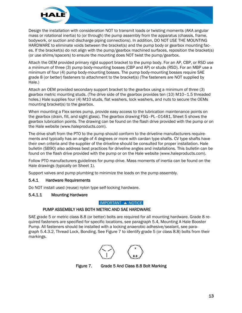
SAE grade 5 or metric class 8.8 (or better) bolts are required for all mounting hardware. Grade 8 re-quired fasteners are specified for specific locations, see paragraph 5.4, Mounting A Hale Booster Pump. All fasteners should be installed with a locking anaerobic adhesive/sealant, see para-graph 5.4.3.2, Thread Lock, Bonding. See Figure 7 to identify grade 5 (or class 8.8) bolts from their markings.
Figure 7. Grade 5 And Class 8.8 Bolt Marking
14
5.4.1.2 Thread Lock, Bonding, Or Sealant Compound
Loctite™ thread lock, bonding, or sealant (or suitable equivalent/substitute) shall be used when di-rected. Loctite™ Thread Lock was used during factory assembly for all fasteners/hardware requiring the use of a thread lock. Additionally, Loctite™ for sealing NPT fittings/plugs listed below as Sealant below.
• Thread Lock • Sealant 243 or 680 580
Loctite® is a Registered Trademark of the Henkel Corporation.
5.4.1.3 Driveshaft Hardware
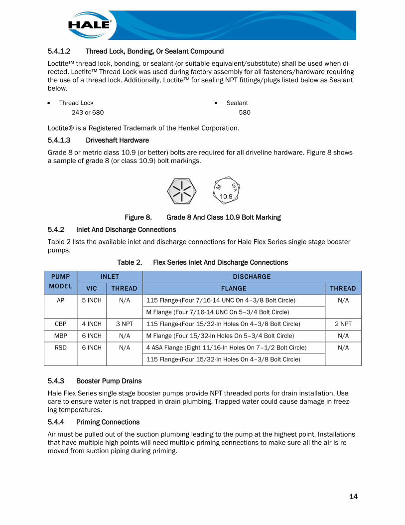
Grade 8 or metric class 10.9 (or better) bolts are required for all driveline hardware. Figure 8 shows a sample of grade 8 (or class 10.9) bolt markings.
Figure 8. Grade 8 And Class 10.9 Bolt Marking
5.4.2 Inlet And Discharge Connections
Table 2 lists the available inlet and discharge connections for Hale Flex Series single stage booster pumps.
Table 2. Flex Series Inlet And Discharge Connections
PUMP MODEL
INLET DISCHARGE
VIC THREAD FLANGE THREAD
AP 5 INCH N/A 115 Flange-(Four 7/16-14 UNC On 4–3/8 Bolt Circle) N/A
M Flange (Four 7/16-14 UNC On 5–3/4 Bolt Circle)
CBP 4 INCH 3 NPT 115 Flange-(Four 15/32-In Holes On 4–3/8 Bolt Circle) 2 NPT
MBP 6 INCH N/A M Flange (Four 15/32-In Holes On 5–3/4 Bolt Circle) N/A
RSD 6 INCH N/A 4 ASA Flange (Eight 11/16-In Holes On 7–1/2 Bolt Circle) N/A
115 Flange-(Four 15/32-In Holes On 4–3/8 Bolt Circle)
5.4.3 Booster Pump Drains
Hale Flex Series single stage booster pumps provide NPT threaded ports for drain installation. Use care to ensure water is not trapped in drain plumbing. Trapped water could cause damage in freez-ing temperatures.
5.4.4 Priming Connections
Air must be pulled out of the suction plumbing leading to the pump at the highest point. Installations that have multiple high points will need multiple priming connections to make sure all the air is re-moved from suction piping during priming.
15
6. COMMISSIONING, STARTUP, OPERATION, AND SHUTDOWN This section provides basic information for the commissioning, startup, operation, and shutdown of the Hale booster pump only. All operators should be trained and qualified.
ALWAYS FOLLOW PROPER OPERATING PROCEDURES. THE PUMP OPERATOR AND INDI-VIDUALS AROUND THE APPARATUS MUST BE FAMILIAR WITH THE PUMP OPERATING IN-STRUCTIONS AS WELL AS OTHER OPERATING GUIDELINES FOR THE APPARATUS, AND ACCESSORIES.
6.1. Installation Verification
Hale recommends using NFPA 1901, ANNEX B, Figure B.5.1(a), Fire Apparatus Delivery Inspection Form or similar guide as well as purchasing specs to inspect a new apparatus.
6.2. Performance Verification
Hale provides the OEM/apparatus builder a certification that the pump meets or exceeds the per-formance requirements when the pump was manufactured. Once the OEM/apparatus builder has installed the pump the completed apparatus should be tested. Performance testing data should be part of the delivery documentation provided by the OEM/apparatus builder. Actual installed perfor-mance may be determined by the powertrain and gear ratios selected so refer to rating chart and vehicle manufacturer performance data for limits on pump performance and operating pressure lim-its.
6.3. Initial Startup
ALWAYS FOLLOW PROPER OPERATING PROCEDURES. THE PUMP OPERATOR AND INDI-VIDUALS AROUND THE APPARATUS MUST BE FAMILIAR WITH THE PUMP OPERATING IN-STRUCTIONS AS WELL AS OTHER OPERATING GUIDELINES FOR THE APPARATUS, AND ACCESSORIES.
DO NOT EXCEED OPERATING PRESSURE LIMITS OF PUMP, INSTALLED PLUMBING, HOSE(S), OR EQUIPMENT IN USE.
DO NOT REACH INSIDE THE PUMP SUCTION WHEN THE ENGINE IS RUNNING. CONTACT WITH MOVING COMPONENTS MAY RESULT IN SERIOUS INJURY. DO NOT REMOVE OR AL-TER GUARDS.
ALWAYS USE PROPER PPE. OIL MAY BE TOXIC. DISPOSE OF OIL PROPERLY PER AHJ GUIDELINES.
FOLLOW DEPARTMENT PROCEDURES TO SET WHEEL CHOCKS WHEN PUMPING
HALE PUMPS ARE SHIPPED WITHOUT OIL. FILL GEARBOX WITH FLUID LISTED IN TABLE 5 BEFORE OPERATION.
16
FOLLOW PTO AND VEHICLE MANUFACTURER PTO INSTRUCTIONS.
OPEN AT LEAST ONE DISCHARGE VALVE SLIGHTLY TO PREVENT THE PUMP FROM OVER-HEATING. OVERHEATING CAN DAMAGE THE PUMP SEAL, AND OTHER PUMP PARTS.
Before the initial startup of pump check the following:
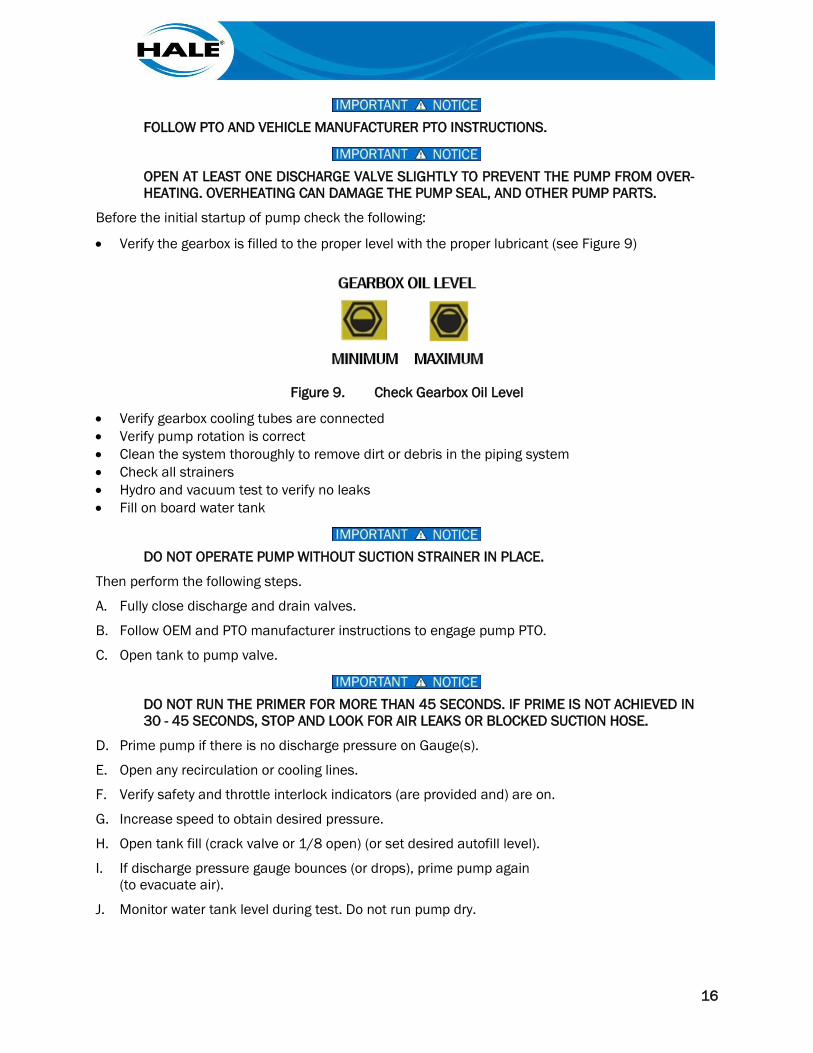
• Verify the gearbox is filled to the proper level with the proper lubricant (see Figure 9)
Figure 9. Check Gearbox Oil Level
• Verify gearbox cooling tubes are connected • Verify pump rotation is correct • Clean the system thoroughly to remove dirt or debris in the piping system • Check all strainers • Hydro and vacuum test to verify no leaks • Fill on board water tank
DO NOT OPERATE PUMP WITHOUT SUCTION STRAINER IN PLACE.
Then perform the following steps.
A. Fully close discharge and drain valves.
B. Follow OEM and PTO manufacturer instructions to engage pump PTO.
C. Open tank to pump valve.
DO NOT RUN THE PRIMER FOR MORE THAN 45 SECONDS. IF PRIME IS NOT ACHIEVED IN 30 - 45 SECONDS, STOP AND LOOK FOR AIR LEAKS OR BLOCKED SUCTION HOSE.
D. Prime pump if there is no discharge pressure on Gauge(s).
E. Open any recirculation or cooling lines.
F. Verify safety and throttle interlock indicators (are provided and) are on.
G. Increase speed to obtain desired pressure.
H. Open tank fill (crack valve or 1/8 open) (or set desired autofill level).
I. If discharge pressure gauge bounces (or drops), prime pump again (to evacuate air).
J. Monitor water tank level during test. Do not run pump dry.
17
K. If pump fails to reach desired pressure, perform the following:
1. Stop pump (disengage PTO).
2. Check for leaks and prime pump again.
3. Restart pump.
L. Monitor pump for vibration and noise, leakage, or loss of performance.
DO NOT USE THE RED IDLE BUTTON UNLESS AN EMERGENCY AS DEFINED BY THE AHJ EXISTS.
M. Stop pump if anything is out of norm, shut down the pump immediately and correct the problem.
DO NOT OPERATE PUMP WITHOUT WATER OR WITHOUT DISCHARGING WATER FOR EX-TENDED TIME, IT MAY OVERHEAT CAUSING DAMAGE.
DO NOT EXCEED 15 DEGREE ANGLE IN OPERATION OF PUMP SYSTEM.
N. Operate pump for 10 minutes to evaluate operation and return to idle, close dis-charge valves, and then disengage PTO to stop pump.
6.4. Draft Operation Notes
DO NOT LEAVE THE DRIVERS POSITION IN THE CAB OR OPEN THE THROTTLE UNLESS ALL SAFETY INTERLOCK INDICATORS ARE ILLUMINATED.
PUMP DISCHARGE PRESSURE SHOULD INCREASE WITH ENGINE SPEED WHEN OPENING THROTTLE. IF ENGINE SPEED INCREASES WITHOUT INCREASE IN PRESSURE, THE PUMP MAY BE CAVITATING.
DO NOT RUN ENGINE HIGHER THAN 1200 RPM DURING PRIMING.
IF THE DISCHARGE PRESSURE DOES NOT INCREASE, AND INTAKE GAUGE READING DOES NOT FALL BELOW ZERO (0), OR THE PRIMING PUMP DOES NOT DISCHARGE WA-TER TO THE GROUND WITHIN 30 SECONDS, STOP THE PUMP AND CHECK FOR AIR LEAKS.
DO NOT ALLOW A WHIRLPOOL AT THE SUCTION STRAINER WHEN DRAFTING.
Draft operation involves lifting water from static source to the pump. Special considerations must be made for draft operations, so in addition to the instructions in paragraph 6.3, note the following.
• Keep all valves closed until discharge pressure is achieved. • Lift should not exceed 10 feet (3m) per NFPA. Lift capability can be reduced by different condi-
tions. See FSG–MNL–00184, Technical Manual For Hale Single Stage Booster Pumps, Table 3, Table 5, and Table 6 for losses information.
18
• Suction hose should not have humps in it for best draft operation. • Suction hose should be in clean area and not pull debris off the bottom of water source. • Suction hose rubber washer must be in excellent shape to hold vacuum. • Suction strainer should be clean and should be rated for flow of the pump. • When priming the compound gauge should move to lower vacuum even before water is dis-
charged. If it doesn’t move during priming, stop pump and check for leaks. • Open valves slowly and allow hose to fill. Maintain pressure with primer as required. • Adjust throttle and discharge valves to attain desired flow and pressure. • Set pressure control per its operating instructions (if so equipped). • To shut down, reduce throttle and close valves (to hold prime) before disengaging pump.
For additional information, see FSG–MNL–00184, Technical Manual For Hale Single Stage Booster Pumps. The manual is contained on the flash drive provided with the pump or on the Hale Products website (www.haleproducts.com).
6.5. Hydrant Or Relay Operation
ALLOWING INTAKE PRESSURES TO FALL BELOW ESTABLISHED LIMITS MAY RESULT IN DAMAGE TO THE WATER SUPPLY PIPING WHEN PUMPING FROM HYDRANT.
A hydrant or relay operation delivers water to the pump inlet with positive pressure. Operation is simi-lar to tank operation (refer to paragraph 6.3) with some differences noted below.
• Tank to Pump valve should remain closed when operating from positive inlet pressure. • Primer is not typically needed. Open any discharge valve, including tank fill to evacuate air from
pump and plumbing. • Bleed off all air from water supply hoses before opening intake valve or beginning pumping oper-
ations. • Cavitation is possible from hydrant or relay, see Section 6.6.
6.6. Pump Cavitation
Cavitation — The sudden formation and collapse of low-pressure bubbles in the pump flow. The re-sulting forces can be as damaging as striking the metal with a hammer. Cavitation within a pump may sound like a hammer banging or rocks or sometimes it is described as ‘marbles’.
Cavitation can occur while pumping from draft, in relay, or from a hydrant. The operator must be aware of the warning signs and correct the situation, or serious damage to the pump may occur.
The way to eliminate cavitation is to increase water supply to the pump, or decrease the amount of water discharged from the pump.
See FSG–MNL–00184, Technical Manual For Hale Single Stage Booster Pumps, for more infor-mation and charts on how different conditions affect pump lift and cavitation.
6.6.1 Discharge Pressure Cavitation Warning Signs
In a properly functioning pump, an increase in RPM will increase the discharge pressure and volume. If an increase in engine RPM that does not cause an increase in the pump discharge pressure, the pump is most likely in cavitation. Gauge needle bounce is a common sign of cavitation.
6.6.2 Vacuum Compound Gauge Warning Signs
The operator should not depend entirely on the vacuum (compound) gauge to indicate when a pump is nearing cavitation. The vacuum gauge does not take into account ambient temperature or atmos-pheric pressure and is not always accurate near zero on the scale.
19
6.6.3 General Considerations to Prevent Cavitation
Consider the following to avoid conditions that lead to cavitation.
• Regularly inspect suction hoses and gaskets to check for air leaks. • Use the proper suction hose size and length for the pump flow rating. • Use caution with intake valves to minimize pressure loss. • Cavitation can also occur when air enters the pump. If an air leak is suspected, discontinue
pumping and perform pressure and vacuum leak tests. • Low barometer from a storm and high water temperature can increase cavitation. • Know your elevation. Pump performance is reduced at higher elevations where there is less air
pressure to push the water into the pump (similar to low barometer).
6.7. Post Operation Notes
Unless local procedures exist, perform the following steps at the end of all operations.
A. Return to idle slowly.
NOTE
Use the red idle button ONLY when an emergency exists.
B. If local procedures require storing the pump dry, drain pump.
NOTE
If salt water (sea or brackish), contaminated water, or foam solution was used; flush the pump with fresh water.
C. Fill out pump run log. (Typically, indicating total pumping time and report all issues or malfunctions and/or irregularities to AHJ immediately.)

20
THIS PAGE INTENTIONALLY BLANK.
21
7. PREVENTIVE MAINTENANCE See FSG–MNL–00184, Technical Manual For Hale Single Stage Booster Pumps, on the flash drive provided with the pump or on the Hale website (www.haleproducts.com) for additional information. A local FAST can also be found on the Hale website and may be used for additional assistance with maintenance/service.
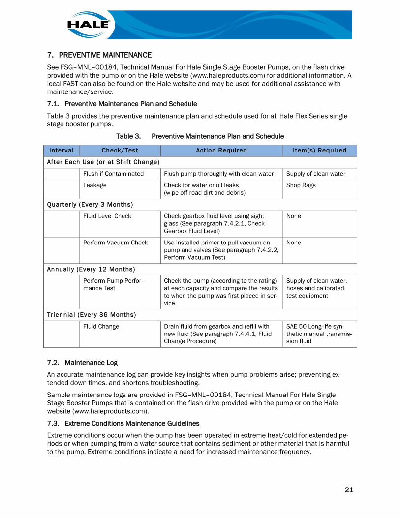
7.1. Preventive Maintenance Plan and Schedule
Table 3 provides the preventive maintenance plan and schedule used for all Hale Flex Series single stage booster pumps.
Table 3. Preventive Maintenance Plan and Schedule
Interval Check/Test Action Required Item(s) Required
After Each Use (or at Shift Change)
Flush if Contaminated Flush pump thoroughly with clean water Supply of clean water
Leakage Check for water or oil leaks (wipe off road dirt and debris)
Shop Rags
Quarterly (Every 3 Months)
Fluid Level Check Check gearbox fluid level using sight glass (See paragraph 7.4.2.1, Check Gearbox Fluid Level)
None
Perform Vacuum Check Use installed primer to pull vacuum on pump and valves (See paragraph 7.4.2.2, Perform Vacuum Test)
None
Annually (Every 12 Months)
Perform Pump Perfor-mance Test
Check the pump (according to the rating) at each capacity and compare the results to when the pump was first placed in ser-vice
Supply of clean water, hoses and calibrated test equipment
Triennial (Every 36 Months)
Fluid Change Drain fluid from gearbox and refill with new fluid (See paragraph 7.4.4.1, Fluid Change Procedure)
SAE 50 Long-life syn-thetic manual transmis-sion fluid
7.2. Maintenance Log
An accurate maintenance log can provide key insights when pump problems arise; preventing ex-tended down times, and shortens troubleshooting.
Sample maintenance logs are provided in FSG–MNL–00184, Technical Manual For Hale Single Stage Booster Pumps that is contained on the flash drive provided with the pump or on the Hale website (www.haleproducts.com).
7.3. Extreme Conditions Maintenance Guidelines
Extreme conditions occur when the pump has been operated in extreme heat/cold for extended pe-riods or when pumping from a water source that contains sediment or other material that is harmful to the pump. Extreme conditions indicate a need for increased maintenance frequency.
22
7.3.1 Freezing Weather
Installations in colder climates may have special cold weather features. Refer to apparatus manufac-turer/OEM documentation and to the additional information provided below.
• Maintain water circulation in cold weather to prevent freezing. • Some installations may provide an air fitting (or fittings) to purge water from the plumbing. • Some installations may need to use antifreeze to winterize the apparatus properly during cold
storage.
7.3.2 Contaminated Water
After pumping salt water, contaminated water or foam solution, or if water containing sand or other foreign matter was used, connect the pump to a fresh water hydrant or other source of clean fresh water and flush the contaminants out of the pump.
7.4. Booster Pump Preventive Maintenance Procedures
Perform procedures provided in the following paragraphs on the schedule indicated in Table 3.
7.4.1 After Each Use
A. Inspect the following:
1. Suction hose
2. Rubber washers
3. Suction tube cap washers
4. Suction hose adapters
5. Suction strainer(s)
B. Remove any foreign matter from hose(s) and coupling(s).
C. Replace all worn or damaged washer(s) and lubricate as required.
D. Verify all discharge and drain valves are closed.
E. Tighten suction caps.
F. If procedures call for a wet pump, open tank fill valve (removes trapped air).
1. Close valve after several minutes.
2. Check apparatus for signs of leaks.
7.4.2 Quarterly Maintenance (every three months)
Perform the following every three months at a minimum (more often is conditions indicate the need).
7.4.2.1 Check Gearbox Fluid Level
Only use lubricants referenced in paragraph 7.4.4.1.1., Recommended Gearbox Lubricants.
If the type of fluid found in the gearbox is unknown, perform a fluid change as instructed in para-graph 7.4.4.1, Fluid Change Procedure.
A. Locate Oil Level Sight Glass. (See Hale drawing FSG–PL–01481, found on the flash drive provided with the pump or on the Hale website [www.haleproducts.com].)
B. Visually check fluid level. (See Figure 9, on page 16.)
C. If fluid level is out of range, perform applicable portion of Fluid Change Procedure. (See paragraph 7.4.4.1 on page 24.)
23
7.4.2.2 Perform Vacuum Test
Verify pump maintains a vacuum as follows.
A. Close all valves.
B. Ensure all caps are in place and tightened.
C. Use primer to pull vacuum of 22 (± 2) in Hg.
D. Verify apparatus maintains vacuum for 5 minutes.
NOTE
A vacuum loss of up to 2 inches per minute is the maximum loss permitted.
7.4.3 Annual Pump Maintenance
Perform procedures provided in the following paragraphs on the schedule indicated in Table 3.
7.4.3.1 Performance Testing
The yearly performance test consists of checking the pump performance and comparing the results to when the pump first placed in service. One place to record the performance tests results is on Figure C.3(c) found in Annex C of NFPA 1911.
Pump Testing Overview
The performance test provides a measure of any performance deterioration. Testing the pump under the same conditions each year is key to understanding if there are any concerns with pump perfor-mance. Using the original vehicle pump test data delivered with the apparatus, repeat this test at delivery and record this data as the base line performance.
Because pump performance specifies both flow and pressure, it is necessary to restrict the flow somewhat to build up the pump pressure. In normal pumping, this restriction would be caused by the friction loss in the lines and the nozzle. However, depending on line loss alone would require a large amount of hose for some tests. It is common practice to use short lengths of hose and gate the dis-charge valves at the pump to maintain pressure.
Testing Equipment And Materials
NOTE
Refer to local procedures for pump testing procedures and practices.
To accurately test pumper performance, requires a calibrated Pitot gauge (or a calibrated flow meter) and a vacuum gauge (or manometer) as well as a calibrated discharge pressure gauge.
Use pressure readings from the Pitot gauge. The volume pumped is then determined by referring to nozzle tables. The Akron Brass website (www.AkronBrass.com) has a variety of flow test kits availa-ble.
7.4.3.1.1 Test Procedure
NOTES
Run engine for 15 to 20 minutes to stabilize engine temperature before running pump performance tests.
During annual test, pressure control functions, electrical systems and complete truck op-eration should be verified in addition to pump performance.
If the apparatus does not reach performance levels, refer to FSG–MNL–00184, Tech-nical Manual For Hale Single Stage Booster Pumps.
24
The annual pump test is defined by the original pump performance specification and testing. Wheth-er EN, NFPA, or other standards were used to specify the apparatus construction; using the same testing annually compared to the original specification data provides proactive information for pump maintenance. Utilize test durations long enough to ensure the engine, drivetrain, and pump are all in proper working order.
7.4.4 Triennial Pump Maintenance
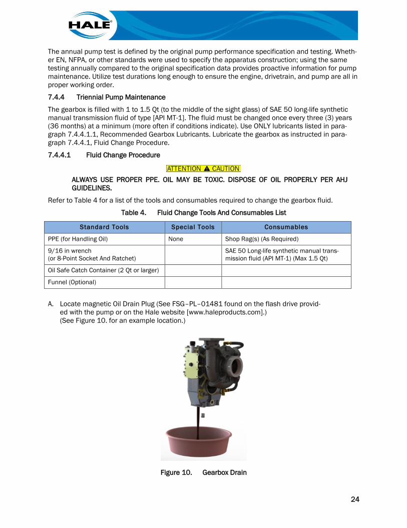
The gearbox is filled with 1 to 1.5 Qt (to the middle of the sight glass) of SAE 50 long-life synthetic manual transmission fluid of type [API MT-1]. The fluid must be changed once every three (3) years (36 months) at a minimum (more often if conditions indicate). Use ONLY lubricants listed in para-graph 7.4.4.1.1, Recommended Gearbox Lubricants. Lubricate the gearbox as instructed in para-graph 7.4.4.1, Fluid Change Procedure.
7.4.4.1 Fluid Change Procedure
ALWAYS USE PROPER PPE. OIL MAY BE TOXIC. DISPOSE OF OIL PROPERLY PER AHJ GUIDELINES.
Refer to Table 4 for a list of the tools and consumables required to change the gearbox fluid.
Table 4. Fluid Change Tools And Consumables List
Standard Tools Special Tools Consumables
PPE (for Handling Oil) None Shop Rag(s) (As Required)
9/16 in wrench (or 8-Point Socket And Ratchet)
SAE 50 Long-life synthetic manual trans-mission fluid (API MT-1) (Max 1.5 Qt)
Oil Safe Catch Container (2 Qt or larger)
Funnel (Optional)
A. Locate magnetic Oil Drain Plug (See FSG–PL–01481 found on the flash drive provid-ed with the pump or on the Hale website [www.haleproducts.com].) (See Figure 10. for an example location.)
Figure 10. Gearbox Drain
25
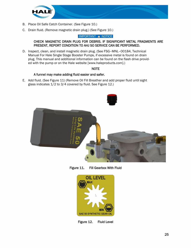
B. Place Oil Safe Catch Container. (See Figure 10.)
C. Drain fluid. (Remove magnetic drain plug.) (See Figure 10.)
CHECK MAGNETIC DRAIN PLUG FOR DEBRIS. IF SIGNIFICANT METAL FRAGMENTS ARE PRESENT, REPORT CONDITION TO AHJ SO SERVICE CAN BE PERFORMED.
D. Inspect, clean, and install magnetic drain plug. (See FSG–MNL–00184, Technical Manual For Hale Single Stage Booster Pumps, if excessive metal is found on drain plug. This manual and additional information can be found on the flash drive provid-ed with the pump or on the Hale website [www.haleproducts.com].)
NOTE
A funnel may make adding fluid easier and safer.
E. Add fluid. (See Figure 11) (Remove Oil Fill Breather and add proper fluid until sight glass indicates 1/2 to 3/4 covered by fluid. See Figure 12.)
Figure 11. Fill Gearbox With Fluid
Figure 12. Fluid Level
26
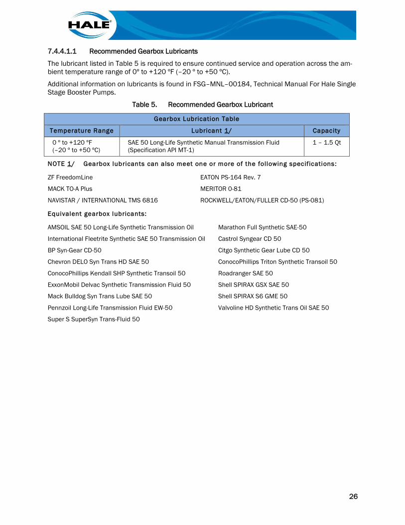
7.4.4.1.1 Recommended Gearbox Lubricants
The lubricant listed in Table 5 is required to ensure continued service and operation across the am-bient temperature range of 0º to +120 ºF (–20 º to +50 ºC).
Additional information on lubricants is found in FSG–MNL–00184, Technical Manual For Hale Single Stage Booster Pumps.
Table 5. Recommended Gearbox Lubricant
Gearbox Lubrication Table
Temperature Range Lubricant 1/ Capacity
0 º to +120 ºF (–20 º to +50 ºC)
SAE 50 Long-Life Synthetic Manual Transmission Fluid (Specification API MT-1)
1 – 1.5 Qt
NOTE 1/ Gearbox lubricants can also meet one or more of the following specifications:
ZF FreedomLine EATON PS-164 Rev. 7
MACK TO-A Plus MERITOR 0-81
NAVISTAR / INTERNATIONAL TMS 6816 ROCKWELL/EATON/FULLER CD-50 (PS-081)
Equivalent gearbox lubricants:
AMSOIL SAE 50 Long-Life Synthetic Transmission Oil Marathon Full Synthetic SAE-50
International Fleetrite Synthetic SAE 50 Transmission Oil Castrol Syngear CD 50
BP Syn-Gear CD-50 Citgo Synthetic Gear Lube CD 50
Chevron DELO Syn Trans HD SAE 50 ConocoPhillips Triton Synthetic Transoil 50
ConocoPhillips Kendall SHP Synthetic Transoil 50 Roadranger SAE 50
ExxonMobil Delvac Synthetic Transmission Fluid 50 Shell SPIRAX GSX SAE 50
Mack Bulldog Syn Trans Lube SAE 50 Shell SPIRAX S6 GME 50
Pennzoil Long-Life Transmission Fluid EW-50 Valvoline HD Synthetic Trans Oil SAE 50
Super S SuperSyn Trans-Fluid 50
27
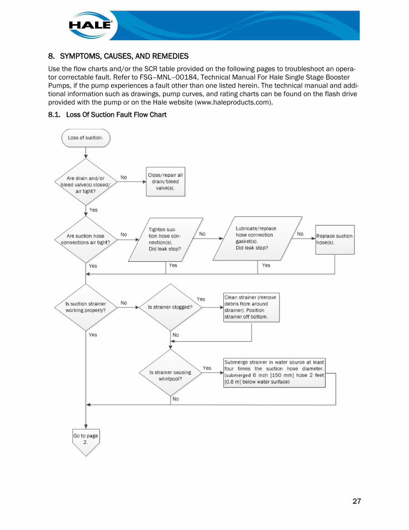
8. SYMPTOMS, CAUSES, AND REMEDIES Use the flow charts and/or the SCR table provided on the following pages to troubleshoot an opera-tor correctable fault. Refer to FSG–MNL–00184, Technical Manual For Hale Single Stage Booster Pumps, if the pump experiences a fault other than one listed herein. The technical manual and addi-tional information such as drawings, pump curves, and rating charts can be found on the flash drive provided with the pump or on the Hale website (www.haleproducts.com).
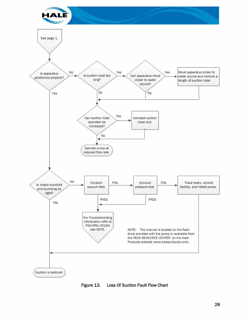
8.1. Loss Of Suction Fault Flow Chart
28
Figure 13. Loss Of Suction Fault Flow Chart
29
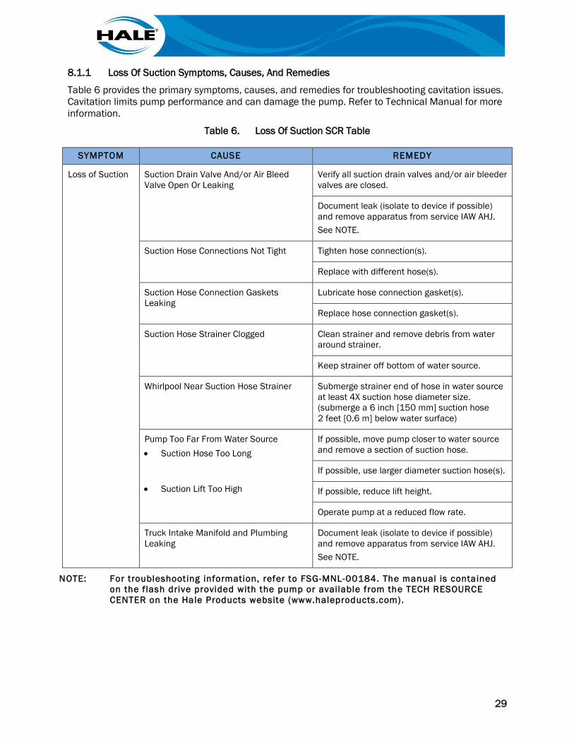
8.1.1 Loss Of Suction Symptoms, Causes, And Remedies
Table 6 provides the primary symptoms, causes, and remedies for troubleshooting cavitation issues. Cavitation limits pump performance and can damage the pump. Refer to Technical Manual for more information.
Table 6. Loss Of Suction SCR Table
NOTE: For troubleshooting information, refer to FSG-MNL-00184. The manual is contained on the f lash drive provided with the pump or available from the TECH RESOURCE CENTER on the Hale Products website (www.haleproducts.com).
SYMPTOM CAUSE REMEDY
Loss of Suction Suction Drain Valve And/or Air Bleed Valve Open Or Leaking
Verify all suction drain valves and/or air bleeder valves are closed.
Document leak (isolate to device if possible) and remove apparatus from service IAW AHJ. See NOTE.
Suction Hose Connections Not Tight Tighten hose connection(s).
Replace with different hose(s).
Suction Hose Connection Gaskets Leaking
Lubricate hose connection gasket(s).
Replace hose connection gasket(s).
Suction Hose Strainer Clogged Clean strainer and remove debris from water around strainer.
Keep strainer off bottom of water source.
Whirlpool Near Suction Hose Strainer Submerge strainer end of hose in water source at least 4X suction hose diameter size. (submerge a 6 inch [150 mm] suction hose 2 feet [0.6 m] below water surface)
Pump Too Far From Water Source • Suction Hose Too Long
• Suction Lift Too High
If possible, move pump closer to water source and remove a section of suction hose.
If possible, use larger diameter suction hose(s).
If possible, reduce lift height.
Operate pump at a reduced flow rate.
Truck Intake Manifold and Plumbing Leaking
Document leak (isolate to device if possible) and remove apparatus from service IAW AHJ. See NOTE.

30
8.2. Cavitation Fault Flow Chart
Figure 14. Cavitation Fault Flow Chart
31
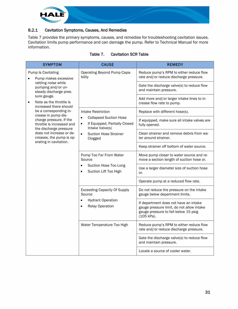
8.2.1 Cavitation Symptoms, Causes, And Remedies
Table 7 provides the primary symptoms, causes, and remedies for troubleshooting cavitation issues. Cavitation limits pump performance and can damage the pump. Refer to Technical Manual for more information.
Table 7. Cavitation SCR Table
SYMPTOM CAUSE REMEDY
Pump Is Cavitating • Pump makes excessive
rattling noise while pumping and/or un-steady discharge pres-sure gauge.
• Note as the throttle is increased there should be a corresponding in-crease in pump dis-charge pressure. If the throttle is increased and the discharge pressure does not increase or de-creases, the pump is op-erating in cavitation.
Operating Beyond Pump Capa-bility
Reduce pump’s RPM to either reduce flow rate and/or reduce discharge pressure.
Gate the discharge valve(s) to reduce flow and maintain pressure.
Add more and/or larger intake lines to in-crease flow rate to pump.
Intake Restriction • Collapsed Suction Hose • If Equipped, Partially Closed
Intake Valve(s) • Suction Hose Strainer
Clogged
Replace with different hose(s).
If equipped, make sure all intake valves are fully opened.
Clean strainer and remove debris from wa-ter around strainer.
Keep strainer off bottom of water source.
Pump Too Far From Water Source • Suction Hose Too Long • Suction Lift Too High
Move pump closer to water source and re-move a section length of suction hose or.
Use a larger diameter size of suction hose or.
Operate pump at a reduced flow rate.
Exceeding Capacity Of Supply Source • Hydrant Operation • Relay Operation
Do not reduce the pressure on the intake gauge below department limits.
If department does not have an intake gauge pressure limit, do not allow intake gauge pressure to fall below 15 psig (105 kPa).
Water Temperature Too High Reduce pump’s RPM to either reduce flow rate and/or reduce discharge pressure.
Gate the discharge valve(s) to reduce flow and maintain pressure.
Locate a source of cooler water.
32
THIS PAGE INTENTIONALLY BLANK.
A–1
APPENDIX A. MANUFACTURER'S INFORMATION
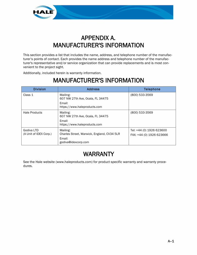
This section provides a list that includes the name, address, and telephone number of the manufac-turer’s points of contact. Each provides the name address and telephone number of the manufac-turer's representative and/or service organization that can provide replacements and is most con-venient to the project sight.
Additionally, included herein is warranty information.
MANUFACTURER'S INFORMATION Division Address Telephone
Class 1 Mailing: 607 NW 27th Ave, Ocala, FL 34475 Email: https://www.haleproducts.com
(800) 533-3569
Hale Products Mailing: 607 NW 27th Ave, Ocala, FL 34475 Email: https://www.haleproducts.com
(800) 533-3569
Godiva LTD (A Unit of IDEX Corp.)
Mailing: Charles Street, Warwick, England, CV34 5LR Email: [email protected]
Tel: +44 (0) 1926 623600 FAX: +44 (0) 1926 623666
WARRANTY See the Hale website (www.haleproducts.com) for product specific warranty and warranty proce-dures.