Embed Size (px)
Citation preview

Gas Endeavour Automatic Gas Flow Measuring System
Operation and Maintenance Manual


Gas Endeavour Automatic Gas Flow Measuring System

Release History Version 1.0 June 2016 Any questions related to this Operation and Maintenance manual should be directed to: Bioprocess Control Sweden AB Scheelevägen 22 SE-223 63 Lund Sweden Tel: +46 (0)46 163950 Fax: +46 (0)46 163959 E-mail: [email protected] Web: www.bioprocesscontrol.com This document contains proprietary information that is protected by copyright. All rights are reserved. No part of this publication may be reproduced in any form whatsoever or translated into any language without the prior, written permission of Bioprocess Control Sweden AB. Copyright © 2016 Bioprocess Control Sweden AB Produced in Sweden

TABLE OF CONTENTS
1 PREFACE ................................................................................................................................ 7 2 POTENTIAL APPLICATIONS OF GAS ENDEAVOUR ................................................. 8
2.1 Wastewater Sector – Activity Determination of Anaerobic Ammonium Oxidising (Anammox) Bacteria .... 8 2.2 Animal Nutrition – In vitro Assessment of Ruminant Feeds ........................................................................... 9 2.3 Greenhouse Gas Emissions from Agriculture – Monitor and Mitigate ........................................................... 9 2.4 Monitoring the Performances of Fermentation Processes – Bioethanol ........................................................ 10 2.5 Monitoring the Performances of Fermentation Processes – Lactic Acid ....................................................... 10 2.6 Batch Dark Fermentation – Evaluation of Biochemical Hydrogen Potential ................................................ 11 2.7 Landfill Gas/Methane Emissions ................................................................................................................... 12 2.8 Human Nutrition and Functional Foods ......................................................................................................... 12
3 DELIVERY CHECKS .......................................................................................................... 14 3.1 Box Content ................................................................................................................................................... 14
4 PRE-COMMISSIONING ..................................................................................................... 15 5 QUALITY RULES AND RECOMMENDATIONS .......................................................... 16 6 SAFETY CONSIDERATIONS ........................................................................................... 17 7 EQUIPMENT DESCRIPTION (DESIGN/FUNCTION) .................................................. 17
7.1 Sample Incubation Unit ................................................................................................................................. 18 7.2 Gas Volume Measuring Device ..................................................................................................................... 19 7.3 Bioreactor Agitation System .......................................................................................................................... 21 7.4 Technical Characteristics ............................................................................................................................... 28
8 OPERATION ........................................................................................................................ 29 8.1 Before Start up ............................................................................................................................................... 29 8.2 Start up ........................................................................................................................................................... 31 8.3 Monitoring ..................................................................................................................................................... 33 8.4 End of Operation ............................................................................................................................................ 34
9 GAS ENDEAVOUR SOFTWARE ...................................................................................... 35 9.1 First Time Connecting and Setting up the Network ...................................................................................... 35 9.2 Finding the IP of Gas Endeavour ................................................................................................................... 41 9.3 Function and Operation .................................................................................................................................. 42 9.4 Troubleshooting ............................................................................................................................................. 56
10 MAINTENANCE .................................................................................................................. 59 APPENDIX A
GAS NORMALISATION CALCULATION FROM DATA GENERATED BY GAS ENDEAVOUR……………………………………………………………………………....... 60 APPENDIX B GAS ANALYSIS BY SELECTIVE CHEMICAL ABSORPTION IN GAS ENDEAVOUR…….……………………………………………………………………………62

APPENDIX C LICENSES FOR THE OPEN SOURCE SOFTWARE ON GAS ENDEAVOUR..65

7
1 PREFACE Bioprocess Control Sweden AB Bioprocess Control Sweden AB (BPC) is a privately held company and market leader in the area of advanced control technologies for the commercial biogas industry, providing technologies and services that support the efficient design and operation of biogas plants & processes. The company was founded in 2006, bringing to market more than 15 years of industry leading research in the area of instrumentation, control and automation of anaerobic digestion processes. At the end of 2009 BPC launched the Automatic Methane Potential Test System I (AMPTS I), a revolutionary product in the area of on-site lab equipment for methane potential analysis. In April 2011 an update version of the AMPTS was made commercially available. The new instrument, AMPTS II, is a well-engineered analytical device developed for on-line measurements of ultra low bio-methane flows produced from the anaerobic digestion of biological degradable substrates. Taking into consideration the high number of the systems already sold to organisations in over 50 countries around the world, there is a clear trend of the AMPTS II becoming the technology of choice for universities, private labs and biogas operators interested in efficiently determining the true methane potential of different substrates. In 2016, Bioprocess Control launched the Gas Endeavour, for on-line measurements of low gas flows produced from any gas generating process at laboratory scale. It is based on the proven AMPTS II technology, and suitable for a wide range of applications, e.g., in animal or human nutrition studies, wastewater treatment, ethanol fermentation, hydrogen production, greenhouse gas emissions.

8
2 POTENTIAL APPLICATIONS OF GAS ENDEAVOUR Bioprocess Control’s automatic platforms are universally applicable for measuring gas flow and volume whenever there is a demand for accurate and precise measurements. These automatic platforms are commonly used in the biogas field. However, other suitable applications include animal or human nutrition studies, wastewater treatment, ethanol fermentation, dark fermentation for biohydrogen production, greenhouse gas emissions, etc.
2.1 Wastewater Sector – Activity Determination of Anaerobic Ammonium Oxidising (Anammox) Bacteria
Removal of nutrients from wastewater is an important step in decreasing the occurrence of eutrophication in the natural water body. Nitrogen is commonly removed in a combined nitrification and denitrification process, which is often inefficient and costly due to a high oxygen demand, the need for an organic carbon source and low microbial activity. Improvements to nitrogen removal processes have been achieved by implementing the Anammox process. The autotrophic bacteria involved in Anammox process convert ammonium and nitrite together into nitrogen gas without the need for any additional organic carbon compound. The Anammox process brings the following advantages in comparison to conventional nitrification / denitrification: i) requires significantly less oxygen, resulting in energy saving of 60%; ii) does not require organic carbon sources; iii) converts ammonium to N2 (inert gas) instead of N2O (pollutant). To keep track of the continued operation in an industrial water treatment process and to have an early warning when changes in the process occur, it is important to measure the activity of the Anammox bacteria regularly. By implementing the Specific Anammox Activity (SAA) assessment as a routine analysis procedure, a stable and well performing process can be ensured. An automated platform using volumetric measurement of nitrogen gas production in batch assays may simplify and standardise the determination of SAA of the bacteria. The instrument for SAA determination will allow simultaneous analysis of a high number of samples/replicates (15), which is very important for statistical significance of the results and essential to evaluate the true SAA under different substrate concentrations and environmental conditions. With the use of a smart instrument for easy and accurate assessment of Anammox activity, the plant manager will obtain deeper knowledge and experience in operating a wastewater treatment plant:
• Get a better insight in the start-up phase and bacterial growth phase • Monitor the continuous functionality of the Anammox process at industrial scale • Use it as an early warning system which enables operators to act on time • Make the operation of WWTPs more cost efficient.

9
2.2 Animal Nutrition – In vitro Assessment of Ruminant Feeds In vitro rumen incubation analyses have already been used for years to evaluate the nutritive qualities of feeds, originally employing end-point measurements focusing on feedstuff digestion. The relation between accumulation of fermentation gases and metabolisable energy content of the feed was established in the 1970s. Since then, measurement techniques based on in vitro gas production have been further developed for feed evaluation experiments. Much of these early reports rely on manual pressure-based gas measurement methods, which are time- and labour intensive. An automated system based on volumetric gas measurements that can minimise human error and workload demand, improve analytical precision and accuracy, as well as standardise data sampling, calculation and presentation, can potentially match the analysis demand for in vitro digestibility test. Such an automated measuring system can offer continuous monitoring of gas production from in vitro digestibility tests with high throughput. A wide range of applications of such an automated system is expected in ruminant feed evaluation, including:
• Continuous monitoring of gas production for the extraction of process kinetic information
• Determination of feed digestibility and its metabolisable energy content • Optimisation of feed composition and nutrient content for livestock • Investigation of feed additives or supplements to optimise ruminal fermentation • Investigation of functional components that may have beneficial effects on methane
emissions and / or organic matter digestibility in vivo • Screening a large range of feeds or additives before testing these in vivo • Comparing different pre-treatments of feed compounds • Comparison of methane emissions from rumen fluid of different domesticated ruminant
species (e.g. bovine vs. small ruminants) fed with similar diets • Perform preliminary studies to investigate the adaptation of animals to the ingestion of a
new diet.
2.3 Greenhouse Gas Emissions from Agriculture – Monitor and Mitigate Animal agriculture is one of the main contributors to greenhouse gas production. In recent years, research and innovation has been initiated to find ways to mitigate the carbon footprint and greenhouse gas emission of animal production systems and agriculture. The work is focused on for instance improving efficiency, productivity, resilience, and adaptive capacity across the agricultural sector. In the area of mitigating the greenhouse gas emission intensity of livestock production, a reduction can be achieved by various means, including: improved animal genotypes including low methane producers, improving feed quality and digestibility, proper manure management focussing on collection, storage and utilisation, and improving carbon sequestration in livestock related production soils. An automated method for batch in vitro tests working with continuous gas production measurement can be a great timesaver and contribute to

10
the mitigation of greenhouse gas emissions. Multiple applications of such an instrument are expected in this field, including:
• Identification of compounds (additives, supplements) to livestock diets in order to limit greenhouse gas emission
• Simulation of greenhouse gas emission from liquid manure during collection in pits below confined animals in vitro
• Investigation of additives to manure to limit greenhouse gas emissions • Comparison of the effect of different storage methods for feed and/or manure on
greenhouse gas emissions in order to select the optimal configuration • Monitoring of greenhouse gas emissions from soil in areas used by livestock • Investigation of the effect of ensilage of feed on greenhouse gas emissions.
2.4 Monitoring the Performances of Fermentation Processes – Bioethanol Concerning the rapid growth of human population, depletion of natural resources, environmental pollution and climate changes, bioethanol has attracted great attention as octane booster, fuel additive, and even as neat fuel. Compared with gasoline, bioethanol has many advantages such as higher octane number, broader flammability limits, higher flame speeds, higher heats of vaporisation, and less emission of SO2 and CO2. Currently, bioethanol is almost always produced by fermentation of grain or sugarcane, but lignocellulosic biomass do not support cost-effective and competitive production. An automatic system for continuous monitoring of an alcoholic or ethanol fermentation process, by following the accumulated volume of carbon dioxide, will have a wide range of capabilities to meet different needs in bioethanol sector, such as:
• Evaluation of feedstock quality and price; the price for e.g. corn represents approximately 45-70% from the total cost production of bioethanol
• Screening on a wide range of cellulosic feedstock • Study of the effects of new enzymes - dosing scheme (e.g. split dose, all upfront) • Development of yeast strains and dosing strategies for more cost efficient conversion
of lignocellulosic biomass to bioethanol • Investigation of fermentation kinetics for fermentation process optimisation • Screening large amount of variables which affect the outputs and identifying the key
factors which can affect the ethanol plant (“by putting a plant in a bottle”) • Process optimisation.
2.5 Monitoring the Performances of Fermentation Processes – Lactic Acid The production of (bulk-) chemicals from renewable resources, instead of using conventional and unsustainable petrochemical resources, has become of new interest in the past few years. Lactic acid is a building block chemical with a wide range of applications (polymer, food and beverage, personal care, pharmaceutical). In the form of poly lactic acid it can be applied in the packaging and textile industries. Lactic acid can be produced in a fermentative process using either bacteria or (engineered) yeast. The production of carbon dioxide during fermentative

11
production of lactic acid, either by bacteria or yeast, can be used as a fermentation indicator to determine the activity of the producing microorganisms, study the kinetics and monitor the process. An automatic system for continuous monitoring of fermentation processes is expected to have a wide range of possible applications in this field, similar to bioethanol fermentation, such as:
• Evaluation of feedstock quality • Screening of a wide range of feedstocks, chose the optimal one for the process • Screening and development of bacteria or yeast strains • Investigation of fermentation kinetics for fermentation process optimisation • Investigation of a large range of parameters that might influence process performance.
2.6 Batch Dark Fermentation – Evaluation of Biochemical Hydrogen Potential
Hydrogen gas is a viable source of energy since hydrogen is a clean energy source with a high energy content of 122 kJ/g. Unlike fossil fuels, no CO2, CO, SOx and NOx emissions are encountered, but only water vapour is released to the atmosphere when hydrogen is used as an energy source. Hydrogen production by bioprocessing of carbohydrate-rich raw materials (e.g. cellulose, starch) has been given considerable attention due to operation under mild conditions (e.g. 35 °C). Biological hydrogen production can occur during photosynthetic or dark-fermentative processes. Dark fermentation is a low-cost technology because acidogenic bacteria neither require light nor pure cultures and therefore have low technological requirements. A wide range of applications of such an automated system is expected in the research and development of biohydrogen production, including:
• Screening and choosing the optimal carbohydrate material (e.g. waste corn, wheat, rice) or mixture producing the highest amount of biohydrogen
• Examining unexploited carbohydrate sources (e.g. agricultural and domestic wastes) • Evaluation of the need of nutrients (e.g., N, P) and minerals (e.g. Fe, Zn, Mg) additions to
accelerate the process and increase the biohydrogen formation yield • Investigation of the activity of microbial flora (i.e. Clostridia, Enterobacter, etc.) used as
inoculum in a dark fermentation process • Study pre-treatment methods to eliminate methanogens from the anaerobic sludge and to
select spore forming hydrogen producers.

12
2.7 Landfill Gas/Methane Emissions Anaerobic biodegradation of municipal wastes in a landfill site produces a large amount of landfill gas, mainly CO2 and CH4. The landfill gas may emit into the atmosphere, which not only contributes to negative impact on greenhouse gas emission control but also endanger the lives of nearby residents. Comprising 40-60% of landfill gas by volume, CH4 is not only potentially an energy source, but also a strong greenhouse gas, with global warming potential of 25 times that of CO2. Accurately estimating landfill methane emissions is important for quantifying a landfill’s greenhouse gas emissions and power generation potential.
• An automated system based on volumetric gas measurements can be a useful part of laboratory scale simulations to study the effect of rainfall, ambient temperature and waste composition on landfills gas generation rates.
2.8 Human Nutrition and Functional Foods The gut microbiota is a highly specialised organ, which directly impacts human health and disease. The significance of the human gut microbiome, both in a biological and a clinical way, is currently the topic of worldwide attention. The digested food has an effect on the metabolic activities and species composition of the human colonic microbiota. In vitro studies are becoming increasingly popular, being faster and less expensive than in vivo techniques, and are ethically superior to them as well. With the in vitro gas production technique the production of fermentative gas is linked to the degradation of foodstuffs. The gas production method can be used for the nutritive evaluation of foods, or for developing and testing of functional foods. A functional food (or ‘health food’) is a food with specific health benefits that go beyond basic nutrition. Due to the increased awareness of food effects and the customers’ growing desires for foods and beverages that fit into a healthy lifestyle, this is a topic more and more people are becoming aware of. Within the field of functional foods, digestive health is one of the biggest segments of the functional foods market. This is a sector where in vitro gas production tests can contribute with valuable knowledge. The functioning of health foods is already tested with in vitro fermentation tests, where often the production of SCFAs is monitored with high-performance liquid chromatography (HPLC) or gas chromatography (GC). As in the general field for human nutrition, however, the gas production method can be used to link the production of gasses to the digestion of food in the hindgut. A wide range of applications is expected for an automated gas measurement platform, including:
• Food evaluation: determine nutritive qualities of foodstuffs. Knowledge can be used for the determination and/or evaluation of (medical) diets, food advice, sports nutrition, nutraceuticals
• Diagnosis of gut related illnesses • Investigate changes in gut microbiota (e.g. during / after treatment with antibiotics, or
related to diet / age / illnesses) • Determine fermentation kinetics of soluble and insoluble fractions of food

13
• Compare nutritive qualities / digestibility of different foodstuffs • Predict hindgut digestion and fermentation in vivo • Predict potential bloating / flatus • Test survivability of functional foods (such as how long will the foods remain active in
the colon?) • Test added nutritional value and added health effect of functional foods • Screen large range of potential functional food components • Determine quickly the best concentration of the functional component to be ingested for
optimal effect • Monitor production of probiotics (CO2 measurement).

14
3 DELIVERY CHECKS At delivery, unpack and check that the contents match with what is listed below in the Section “Box Content”.
If the packaging or the equipment is broken at delivery, please: a) Document and take photos of the parts and packaging b) Inform the transport company at the time of delivery c) Make sure that the transport company documents the incident d) Inform your local distributor or BPC of the incident.
3.1 Box Content See also Chapter 7. Equipment Description (Design/Function) for pictures of the included parts.
15 glass bottles, 500 ml as reactors 15 plastic caps with agitators / motors 15 helical couplings 14 short motor cables 1 long motor cable (from Motor Controller to first motor unit) 1 signal cable (from the Gas Volume Measuring Device to Motor Controller) 15 plastic stoppers with 2 tubing ports and rotating shaft for mixing 1 thermostatic water bath (18 l) 1 plastic glass lid for the water bath, with 15 circular openings 15 evaporation minimising rings for the lid & reactors 15 plastic tubing clamps
GAS VOLUME MEASURING DEVICE 1 water bath package (including water tank, flow cell holder, 15 injection mould flow cells containing magnetic metal pieces, base and protection plate) 1 plastic glass lid for the water tank (including straight connector) 1 manual plastic water pump 1 power adapter (input 100-240 V ∼ 50/60 Hz, output 12 V DC / 5 A) OTHER COMPONENTS 1 shielded Ethernet cord 1 Motor Controller 2 boxes of 15 m flexible Tygon® tubing 1 number markers kit for tubes 15 plastic lids 1 Allen key (for helical couplings) 1 manual

15
OPTIONAL EQUIPMENT
8 glass bottles, 1 l (bottles with one port designed for continuous pH monitoring during the batch fermentation) and 8 stirrers adjusted for 1 l bottles 6 glass bottles, 2 l (bottles with one port designed for continuous pH monitoring during the batch fermentation) and 6 stirrers adjusted for 2 l bottles 1 plastic glass lid for the water bath, with six or eight circular openings for reactors Gas sampling units Gas-absorption unit: Gas absorption bottles: 15 Volume of gas absorption bottles: 100 ml Dimension of unit: 44×30×6 cm
4 PRE-COMMISSIONING The following items are not included in the delivered Gas Endeavour, however they will/may be required to operate the Gas Endeavour:
• Thermometer for temperature indication in the thermostatic water bath • N2, CO2 or a mixture of N2/CO2 to obtain anaerobic conditions during the sample
preparation phase • Silicone spray or other similar lubricant • Additional wall socket adapters (plugs/contacts) (the ones supplied are according to
European, US or UK standards, depending on original purchase order) • If the customer has a GC and is interested in off-line gas composition analysis, gas-
sampling units can be ordered separately from BPC.

16
5 QUALITY RULES AND RECOMMENDATIONS
• The product guarantee provided corresponds to the guarantee stipulated on the confirmed product order form and shipping documentation. The removing of the bottom plate of the Gas Volume Measuring Device is considered as a breach of guarantee.
• For guarantee claims relating to the thermostatic water bath, contact the manufacturer directly (see separate manual for Bioprocess Control VWX).
• BPC recommends using a proper oxygen free gas according to selected test protocol to remove any remaining air in the headspace of the bottles to create anaerobic conditions if that is needed for the experiment.
• When 500 ml bottles are used as reactors, the recommended headspace in the bottles during test analysis is around 200 ml.
• For a high accuracy analysis, Gas Endeavour should not be exposed to mechanical vibrations and/or high frequency radio transmissions.
• Only the parts delivered with the product can be used in the system in order to guarantee the quality and performance of the product.
• The system contains batteries and need to be handled accordingly. • BPC reserves the right to correct any possible text and image errors as well as changes to
technical data in this manual.
Before Getting Started
• Read this manual and additional separate manuals for the individual instruments before installing and using the equipment: • Bioreactor Agitation Systems • Thermostatic Water Bath (Bioprocess Control VWX)
• Keep the instruction manual for future reference and make sure it is easily available for people who regularly use the Gas Endeavour.

17
6 SAFETY CONSIDERATIONS
The Agitation System contains rotating parts. Make sure to tie back any loose hanging objects like clothing or hair when using the instrument. The power adapter for the multifunction brushless DC Agitation System must never be used in the Gas Endeavour.
7 EQUIPMENT DESCRIPTION (DESIGN/FUNCTION) The Gas Endeavour follows the same measuring principles as conventional instruments for gas volume measurements, which make the analysis results fully comparable with standard methods. However, with the Gas Endeavour, the analysis and data recording are fully automatic during the long incubating period, which significantly reduces the time- and labor-demand for carrying out the analysis. Moreover, a high quality of data can be obtained, which can be used to extract kinetic information of the process. This will in turn allow for a much better understanding of the dynamic behavior of a specific substrate, further leading to an improved process operation. The instrument setup can be divided into two units: A and B (please refer to the included photos). In the Sample Incubation Unit, up to 15 test vessels containing small amounts of a sample with suitable microbial inoculum are incubated at a desired temperature in a thermostatic water bath. The media in each vessel is mixed by a slow rotating agitator, while gas is continuously produced from the material. In the Gas Volume Measuring Device, the volume of gas released from the incubation unit is measured using a wet gas flow measuring device with a multi-flow cell arrangement (15 cells). This measuring device works according to the principle of liquid displacement & buoyancy and can monitor ultra low gas flows; a digital pulse is generated when a defined volume of gas flows through the device. An integrated embedded data acquisition system is used to record, display and analyze the results.
18
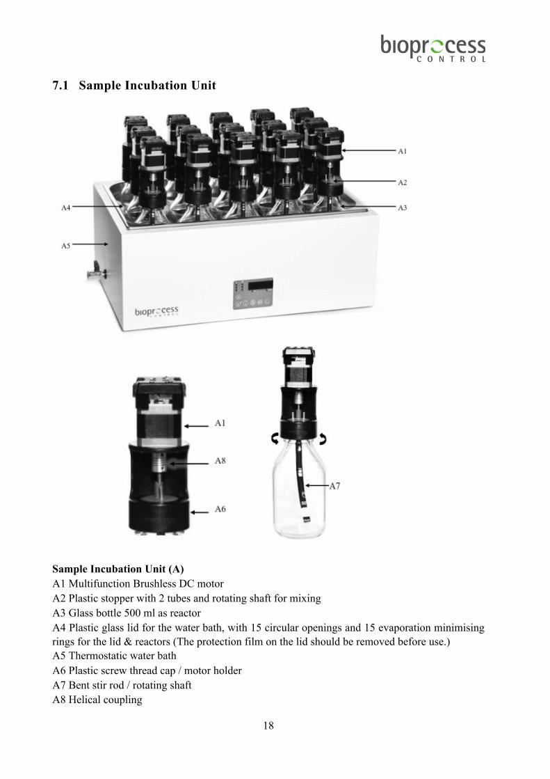
7.1 Sample Incubation Unit
Sample Incubation Unit (A) A1 Multifunction Brushless DC motor A2 Plastic stopper with 2 tubes and rotating shaft for mixing A3 Glass bottle 500 ml as reactor A4 Plastic glass lid for the water bath, with 15 circular openings and 15 evaporation minimising rings for the lid & reactors (The protection film on the lid should be removed before use.) A5 Thermostatic water bath A6 Plastic screw thread cap / motor holder A7 Bent stir rod / rotating shaft A8 Helical coupling

19
7.2 Gas Volume Measuring Device

20
Gas Volume Measuring Device (Unit B) B1 Injection mould flow cell B2 Water bath package (including water tank, flow cell holder, protection plate and electronics) B3 Manual plastic water pump B4 Connection block B5 Motor signal connection socket for the Motor Controller: 12 V DC / 3 A B6 Power connection socket for the power adapter: 12 V DC / 5 A B7 Shielded Ethernet socket B8 Power adapter: 12 V DC / 5 A
21
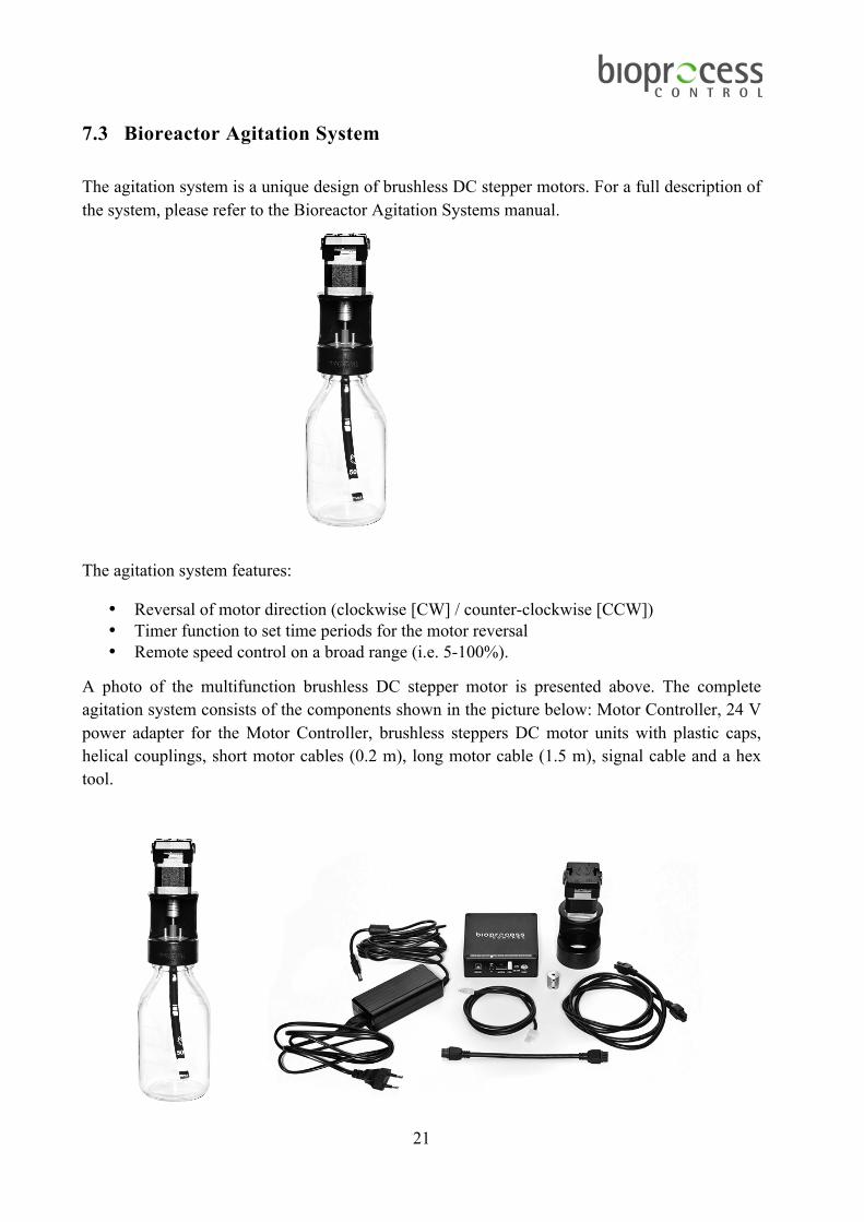
7.3 Bioreactor Agitation System The agitation system is a unique design of brushless DC stepper motors. For a full description of the system, please refer to the Bioreactor Agitation Systems manual.
The agitation system features:
• Reversal of motor direction (clockwise [CW] / counter-clockwise [CCW]) • Timer function to set time periods for the motor reversal • Remote speed control on a broad range (i.e. 5-100%).
A photo of the multifunction brushless DC stepper motor is presented above. The complete agitation system consists of the components shown in the picture below: Motor Controller, 24 V power adapter for the Motor Controller, brushless steppers DC motor units with plastic caps, helical couplings, short motor cables (0.2 m), long motor cable (1.5 m), signal cable and a hex tool.

22
MOTOR CONTROLLER The Motor Controller provides power to the motors via the motor cables, and it is very important that the Motor Controller always is turned off and is unplugged from the power source when any cables are connected or disconnected from the motors. Turning the switch off is not enough. The Motor Controller is the hub of the agitation system. It interprets the speed signal sent from the Gas Volume Measuring Device of the Gas Endeavour and controls the direction of the motors. All the mixers receive the same information from the Motor Controller. The picture below shows the control panel on the front side of the Motor Controller.
The ON / OFF switch (shown in the picture above) turns the power of the Motor Controller on and off. When the switch is ON (in the upper position), the red LED will be lit up to indicate that the system is active. It is recommended to set the switch to OFF before connecting / disconnecting the Motor Controller to / from the power mains. When the AUTO switch on Motor Controller is set to OFF, the mixers will be operated in continuous rotation mode, i.e. the mixers will always rotate in the same direction. Setting the switch to ON will activate the AUTO reversing mode, which will make the Motor Controller change the mixer directions at regular intervals. For the Auto reversing mode to work as intended, the DIRECTION switch on each motor needs to be in the AUTO (middle) position as well. If the switch is in either CW or CCW position, the mixer will start and stop but never change direction. See section Direction Switch for further explanation of the different combinations of settings on the Motor Controller and the motor units.

23
SIGNAL CABLE The Motor Controller receives signals from the test system through an analogue signal cable (pictured below).
WARNING: The position of the signal and grounding terminals of the connectors are reversed on the Motor Controller compared to the Gas Endeavour system. On the Motor Controller, the ground is at the bottom terminal (see the picture below). Always make sure the proper cable is used and that it is inserted the correct way, or the system could be permanently damaged!
MOTOR CABLES The signals from the Motor Controller are distributed to each motor unit through the motor cables (see picture below). They should be connected serially, fastened to the motor units with the help of latches. The 1.5 m cable is used only to connect the “MOTOR” output on the Motor Controller to the first motor.
MIXING INTENSITY The motors can be operated at different speeds ranging from 10-200 RPM. The speed is adjusted linearly between 10 and 200 RPM, referred to as per cent (5 – 100%) in the Gas Endeavour software. At a DC-signal of 0 (zero) V, the motor is out of function, and at 12 V it is rotating at top speed (200 RPM). An acceleration / deceleration ramp is built into the system to provide a smooth transition between different speeds.

24
TIMER TO CONTROL INTERVALS OF MOTOR REVERSAL The rotary Timer switch can be used to set the time that should elapse before the direction is changed. 10 positions are available ranging between 5 s to 1 h.
Timer Switch Position
Time
0 5 s 1 15 s 2 30 s 3 45 s 4 60 s (1 min) 5 120 s (2 min) 6 300 s (5 min) 7 600 s (10 min) 8 1800 s (30 min) 9 3600 s (60 min)
FUSE To protect the Motor Controller, the Printed Circuit Board (PCB) is fitted with a slow-blow 2 A fuse (522.520). If none of the mixers are working even though the power supply is connected, this fuse should be replaced. The fuse is located inside the Motor Controller, which can be opened by removing the four screws placed in each corner of the top cover. (See picture below).

25
MOTOR UNIT Each motor unit has its own driver board, which controls the power distribution to the actual motor. The switches are explained below.
MOTOR ON / OFF SWITCH The ON / OFF switch is located on the side of the motor, and marked on the very top of the motor unit, just above where the actual switch is located. When a mixer is active and power is supplied, an LED next to the ON / OFF switch will be green. If not all mixers will be used, setting the ON / OFF switch to OFF can turn each motor off individually. The motor unit will make a sound to indicate when this is done. It is recommended to set the switch on each Motor Unit to the OFF position before connecting or disconnecting the Motor Controller or any of the motor cables. When the system has been turned off, and then switched back on, it can take up to 8 seconds for it to start up again. DIRECTION SWITCH The DIRECTION switch is located on the side of the motor, and marked on the very top of the motor unit, just above where the actual switch is located. It is used to set the motor to rotate in a CW or a CCW direction. Setting the switch to AUTO gives the Motor Controller automatic control over the reversal of the direction. Below is a table that will show the output of the different combinations of switch settings on the Motor Controller and the motor unit.

26
Settings Mixer output Motor Controller AUTO switch
Motor unit switch Intervals Rotation
ON CW
Starting and stopping according to Motor Controller intervals
Constantly CW
ON AUTO Starting and stopping according to Motor Controller intervals
Reversing directions
ON CCW
Starting and stopping according to Motor Controller intervals
Constantly CCW
OFF CW
N/A Constantly CW
OFF AUTO N/A The latest direction used before the Motor Controller AUTO switch was set to off
OFF CCW
N/A Constantly CCW

27
RESET BUTTON If an error is encountered somewhere on the driver board in the motor unit, a red LED will light up on the side of the motor unit, opposite to where the switches are located. A marking on the top of the motor unit shows where to find it (see picture below). The problems could be e.g. high temperature, a disconnected motor cable, or power loss. If this happens, the mixer can be reset with a quick press on the RESET button. The RESET button is marked on the very top of the motor unit, just above the actual button. It can be reached by using a pen or other pointy object. If the mixer was reset successfully, the red LED will turn off.
POWER The Motor Controller is powered by a 24 V / DC 2.71 A power supply adapter. The power supply is then distributed serially from the Motor Controller, through the 8-pin signal cables, to each motor unit. WARNING: The power supply always has to be disconnected from the Motor Controller before removing or connecting any of the cables from the motors.

28
7.4 Technical Characteristics GENERAL CE certification: this product meets the requirements of applicable CE-directives. A copy of the corresponding Declaration of Conformity is available on request.
Usage: indoors in an environment free of corrosive agents and with normal humidity level Power supply: 100 or 240 V ~ 50 / 60 Hz (thermostatic water bath and power adapter) Tubing material: Tygon® (ID 3.2 mm, OD 4.8 mm) Weight: approx. 28 kg SAMPLE INCUBATION UNIT Maximum number of reactors per system: 15 Reactor material: glass Standard reactor volume: 500 ml Power consumption: 1300 W (maximum) Dimension: 50×30×15 cm Temperature control: up to 100 °C (precision 0.2 °C) Mixing in the reactor: mechanical (adjustable interval and speed), maximum speed 200 rpm GAS VOLUME MEASURING DEVICE Working principle: liquid displacement & buoyancy Up to 15 cells running in parallel Built-in pressure and temperature sensors Measuring resolution: 2 or 10 ml Detection capacity:
i) maximum value: 2×10⁴ flow cell openings per system for each test, approximately equal to 40 or 200 l in total for 2 or 10 ml cells, respectively ii) average value: up to 2.6 or 13 l cumulative gas per channel for each test for 2 or 10 ml cells, respectively
Measuring range for instant gas flow rate: 2 to 12 or 10 to 120 ml per min (for 2 or 10 ml cells) Dimension: 51×44×18 cm Housing: plastic Repeatability: 1%

29
8 OPERATION In this section, references are given to pictures in the Chapter 7. Equipment Description (Design/Function) in the form of a letter and number within parenthesis e.g. (A1).
See also the user manual for the Thermostatic water bath (Bioprocess Control VWX) before installation and use.
8.1 Before Start up REACTORS
a) Perform a simple leakage test for each reactor by creating some overpressure by blocking one of the metal tubing ports and injecting air from the remaining metal tubing port, and then immerse the reactor in water to check if there is any air bubble escaping from the reactor. Make sure that all tubing is properly connected and there is no potential leakage anywhere.
b) Add the sample (e.g. 400 g of mixture between substrate and inoculum), the blank (e.g. 400 g inoculums) and the positive control (specific for each particular application) into the reactors. Use triplicates for statistical significance.
c) Insert the stirrer into the bottle and press down on the motor holder and plastic stopper. Screw until the thread on the bottle is no longer visible. The lid must be properly sealed to ensure that the equipment does not risk being damaged. See picture to the right above for the position of the cap on the reactor bottle. If a system with blue rubber stoppers has been used, and the stoppers have been exchanged for the grey plastic ones, please check the reactor bottles for a plastic ring around the opening. If there is a ring, it has to be removed for the grey plastic stopper to fit properly.
d) The bent stir rod can be fastened to the motor by attaching a helical coupling to it by using
an Allen key to fasten the screws in the coupling. Make sure the metal rod is not pushed too far down and drills a hole in the bottom of the stirrer.

30
THERMOSTATIC WATER BATH Do not install or use the equipment before reading the separate instructions for the thermostatic water bath.
a) Remove the protection film from the plastic glass lid with 15 circular openings (A4) before using it. Place it on top of the water bath, in order to minimise the evaporation of water during the experiment.
b) After inserting all the reactors into the thermostatic water bath (A5) fill it up with enough water to completely cover the equivalent height of the content in the reactors (ca. 8 l). If normal tap water is used, calcareous deposits may appear in the bath and on the heating element. It is therefore recommended to use deionised or distilled water.
c) Place the 15 evaporation minimising rings over the reactor bottlenecks and press down gently so they close the gap between the plastic lid and the reactors.
d) Cut 15 pieces of Tygon® tubing at lengths of about 10 cm and connect them to one of the small plastic tubes on top of the plastic lids of the reactors. Close these tubing pieces with the help of plastic tubing clamps.
e) Cut 15 pieces of Tygon® tubing sufficient in length to couple the second plastic connection on the lid of the reactor to the corresponding tubing connector on the connection block (B4) located on the back of the Gas Endeavour.
MOTOR CONNECTIONS
a) Make sure that the power adapter for the Motor Controller is disconnected from the power supply.
b) The motor units should all have the ON / OFF switch set to the OFF mode. c) Connect one short motor cable to each motor (excluding the last motor in the chain) and
then connect the free end of the cable from motor 1 to the free port on motor 2 and so on until motor 15.
d) The Motor Controller should have the System ON / OFF switch in the OFF mode. e) Connect the long motor cable from motor 1 to the Motor Controller. f) Connect the signal cable from the Motor Controller to the motor signal port on.
GAS VOLUME MEASURING DEVICE
a) Install the Gas Volume Measuring Device on a flat and stable surface. Use appropriate instrumentation (i.e., bubble level device) to verify the horizontality of the surface and to adjust the level of the system placed on the surface.
b) Fill up the water bath with deionised or distilled water. The water level should be within the limits of the marking on the water bath.
c) Make sure to remove the protective film from the transparent lid of the water tank.
31
NETWORK CONNECTION
a) Connect one end of the Ethernet cord to the Gas Volume Measuring Device. b) Connect the other end of the Ethernet cord to a computer or to an internal network. c) Make sure the computer is not connected to a wireless network. If possible temporarily
completely disable the wireless capability. d) Make sure that the network cable is connected to the network prior to connecting the
power supply.
8.2 Start up FLUSHING THE REACTORS
a) If anaerobic conditions are required, disconnect the Tygon® tubes from the Gas Volume Measuring Device before flushing the system with gas.
b) Connect the gas source to the Tygon® tubing with the red tube clamp. c) Open the red tube clamp. d) Flush the reactors with a low gas flow (i.e., 2.5 to 10 l/min) gently for 30 - 120 seconds. e) Stop the flush gas and close the red tube clamp. f) Disconnect the flush gas source. g) Re-connect the Tygon® tubing to the Gas Volume Measuring Device.
Repeat the procedure for all the reactors used in the test.
Important! Before flushing the system, please, disconnect the Tygon® tube from the Gas Volume Measuring Device in order to eliminate the risk of damaging built-in check valves by the high-pressure gas flow. After flushing the system and before starting the data logging, please open manually all the flow cells in the Gas Volume Measuring Device in order to release any remaining flush gas trapped in the flow cell chambers. THERMOSTATIC WATER BATH
a) Start up the thermostatic water bath using the main switch. The green LED indicator is illuminated.
b) Set the operating temperature if it is different from the value set before the last switch-off.
MOTOR AND POWER CABLES
a) Check that all motor cables are connected to each other, and that the long motor cable is connected between the first motor and the Motor Controller.
b) Check that the analogue signal cable is connected between the Motor Controller and the

32
Gas Volume Measuring Device. c) Connect the 12 V power adapter to the Gas Volume Measuring Device, and to a 100-240
V 50/60 Hz standard power socket. After this, connect the 24 V power adapter to the Motor Controller and to a 100-240 V 50/60 Hz standard power socket. IMPORTANT: The power adapters for the Motor Controller and the Gas Volume Measuring Device of Gas Endeavour have different characteristics. Make sure the right ones are used, or the system could be permanently damaged!
d) Set the System switch on the Motor Controller to ON. e) Set the ON / OFF switches on each motor unit to ON.
SOFTWARE
a) Make sure that the shielded Ethernet cord is connected to the Gas Volume Measuring Device and a computer or a local internal network. Make sure that the network cable is connected prior to connecting the power supply.
b) The Gas Endeavour software for embedded data acquisition and the built in web server will be loaded and started up automatically after powering up the Gas Volume Measuring Device.
c) Follow the instructions in Chapter 9 (Gas Endeavour Software) step by step for accessing the software interface through an Internet browser, such as Google Chrome or Safari. Using Google Chrome is always recommended.

33
d) When software and experiment configuration have been completed, start the data logging function of the Gas Endeavour software. In the Control menu, activate all the cells for data registration. Open each cell in the Gas Volume Measuring Device manually several times in numerical order from 1-15, and repeat in total 3 times. Follow the corresponding result of each opening on the plots in the Graph menu of the software to make sure that both the detection system and data acquisition system function properly.
e) Check the files obtained when generating a report in the Download report menu. Download these files and open them using Microsoft Excel 2007 (or a later version). If prompted by the software to install Adobe Flash, please do so.
f) Re-start the Gas Endeavour software by pressing pause, then the “End experiment” and finally the “Start experiment” buttons for each individual cell.
8.3 Monitoring REACTORS
a) If possible, perform a GC analysis to determine the gas composition in the raw gas samples. The raw gas can be sampled by adding a T-valve to the Tygon® tubing attached to each reactor.
b) Periodically check that there is mixing in each reactor. c) Make sure that the Tygon® tubing is not sharply bent, interfering with the gas flow, and
that it doesn´t take damage by the rotating parts of the stirrer / motor.
THERMOSTATIC WATER BATH
a) Periodically check the water level in the thermostatic water bath. b) Fill up with additional deionised or distilled water when necessary.
GAS VOLUME MEASURING DEVICE
a) Check that the water level in the thermostatic water bath for the Gas Volume Measuring Device is within the recommended range.
b) Fill up with additional deionised or distilled water to the recommended water level when necessary.
SOFTWARE See Chapter 9 (Gas Endeavour Software) for information regarding software function and operation.
34
8.4 End of Operation a) Note the total running time if this is of interest. In the saved data files, the last data
collected will be from the last opening of a cell. b) Generate a report in the Download report menu. Download the report and open it to make
sure that the report has been generated properly and that no errors occurred while downloading the file.
c) Stop the logging by pressing the pause button and then the stop button. Note: When pressing the stop button, the experiment associated with that particular cell can no longer be continued.
d) Turn off the thermostatic water bath. e) Set the ON / OFF switch on each motor unit to OFF. f) Set the System switch on the Motor Controller to OFF. g) Unplug the power adapters (for the Motor Controller and the Gas Volume Measuring
Device) from the power source. h) Empty the water from the thermostatic water bath by using the manual plastic water
pump only. Do not pour water out from the water bath in any other way. Directly pouring out the water without using the pump might allow water to flow into the space between the water tank and the stand, as well as flow into the stand. There is a potential risk of electronic damage even if only very limited amounts of water are accidently in contact with the electronic circuit boards inside the stand.
DATA HANDLING When a report is generated, save the report in a desired folder on the local computer used to visualize the software interface.
See also Appendix and Chapter 9. Gas Endeavour Software for details on the data handling. The report files are of XML format (with the ending “.xml”), can be generated anytime during the experiment, and can be used for further data analysis and curve plotting in Microsoft Excel or other software capable of reading this file format. The name of data file is automatically generated, consisting of the actual date and time. For example, a file saved on 1st of April 2011 at 12:30 will get the name “report_2011-04-01_1230.xml” or “report_2011-04-01_1230.csv”. The following data are stored in the files:
a) Time (hours, days) since the start of the experiment b) The total gas volume in liter (l) or normalised liter (Nl) (total accumulated gas volume
during the experiment) depending on the settings selected before starting the experiment c) Average values with normalised values (Nml/h or Nml/day) or without normalisation
(ml/h or ml/day) depending on the settings selected before starting the experiment d) Experimental parameters such as process temperature (ºC), mixer ON / OFF times (s),
mixer speed adjustment (%).

35
If the normalisation is selected in the experiment settings, the generated file contains the volume of gas already normalised (1.0 standard atmospheric pressure, 0oC and zero moisture content). The calculations are carried out to compensate for pressure, temperature and saturated moisture content at the above given conditions (based on the values of pressure and temperature registered by the sensors from the Gas Volume Measuring Device).
9 GAS ENDEAVOUR SOFTWARE
9.1 First Time Connecting and Setting up the Network Important! Make sure the computer is not connected to a wireless network. If possible, temporarily completely disable the wireless capability.
a) Connect the shielded Ethernet cable to the Gas Volume Measuring Device. b) Connect the shielded Ethernet cable to a computer.
Important! Make sure that the network cable is connected prior to connecting the power. c) Connect the power supply (12 V DC) to a standard 100-240 V ∼ 50/60 Hz power socket.
WINDOWS 8 Below screenshots are from Windows 8, but they can also be used as a guide for Windows 10, as the set up and procedure is the same there.
a) Start Menu, right-click in lower left corner and select “Network Connections”.

36
b) Right-click on the appropriate network adapter and select “Properties”.
c) Select “Internet Protocol Version 4 (TCP/IPv4)” and click on the button marked “Properties”.

37
d) Write down the initial settings (e.g., IP address, subnet mask) if needed for future reference.
e) Select “Use the following IP address” and enter the following values in the fields:
IP address: 192.168.10.10 Subnet mask: 255.255.255.0
f) Select “OK”. g) Click “OK” and close the remaining windows.

38
WINDOWS 7
a) In the Windows Start Menu, select “Control Panel”. b) In the Control Panel, select “Network and Internet”. c) Select “Network and Sharing Center”.
d) On the left side of the window, select “Change adapter settings”.
e) Right click on the appropriate network adapter and select “Properties”. Usually this is named “Local Area Connection”, possibly followed by a number. It is important that the adapter corresponding to the connected Ethernet cable is selected.
f) Select “Internet Protocol Version 4 (TCP/IPv4)” and click on the button marked “Properties”.
g) Write down the initial settings (e.g., IP address, subnet mask) if needed for future reference.
h) Select “Use the following IP address” and enter the following values in the fields:
IP address: 192.168.10.10 Subnet mask: 255.255.255.0
i) Select “OK”. j) Click “Close” in the remaining window.

39
WINDOWS XP
a) In the Windows Start Menu, select “Control Panel”. b) Select “Network Connections”. c) Right click on the appropriate network adapter and select “Properties”. Usually this is
named “Local Area Connection”, possibly followed by a number. It is important that the adapter corresponding to the connected Ethernet cable is selected.
d) Select “Internet Protocol” and click on the button marked “Properties”. e) Write down the initial settings (e.g., IP address, subnet mask). f) Select “Use the following IP address” and enter the following values in the fields:
IP address: 192.168.10.10 Subnet mask: 255.255.255.0
g) Select “OK”. h) Select “OK” in the remaining window.

40
MAC OS X
Select the Apple Menu button and select “System Preferences”.
a) Select “Network”. b) Write down the initial settings (e.g., IP address, subnet mask). c) Select “Manually” from the “configure IPv4” dropdown menu and enter the following
values in the fields:
IP Address: 192.168.10.10 Subnet mask: 255.255.255.0
d) Select “Apply”.
ALL SYSTEMS To access the instrument, open a web browser. (Google Chrome is recommended as it provides the best and most compatible feature set for the Gas Endeavour). In the address field enter, http://192.168.10.11 The address can be saved in the bookmarks of the web browser. If multiple Gas Endeavour units are installed, log the IP address for each individual system. Below is located a quick guide to make sure that all settings have been made correctly. Gas Endeavour IP Address 192.168.10.11 Subnet mask 255.255.255.0 Computer IP Address 192.168.10.10 Subnet mask 255.255.255.0 Please note that the IP address for the computer and the IP address for the Gas Endeavour are different. This is a design requirement of the IP protocol. Care needs to be taken so that the same address is not used in both locations as it will render the system inaccessible from the designated computer.

41
Connect the system to a network If the system is to be connected to an internal network (and/or the Internet), please follow the steps below:
I. Log in to the Gas Endeavour by entering the user name (user) and the password (bpc). II. In the web browser window, showing the Gas Endeavour web application, click on the tab
marked “System”. III. If using a Dynamic Host Configuration Protocol (DHCP) server located on the internal
network to assign an IP address to the system, click on the checkbox marked “Obtain an IP address and DNS information automatically”, select “Apply network settings” and click “Yes” in the confirmation dialogue.
If the system is not supposed to use a DHCP server, manually enter the required network information followed by selecting “Apply network settings” and clicking “Yes” in the confirmation dialogue. Important! Changing the network settings might make your system unreachable if you enter incorrect information. Contact the IT department to make sure that the correct settings are applied. If, for any reason, the wrong settings are applied, the Gas Endeavour can be reset to the factory default settings by pressing the reset button located at the back of the unit. This will reset the unit to its default state with the default network settings.
IV. Disconnect the provided shielded Ethernet cable from the computer (not the Gas Endeavour) and connect it to the internal network.
V. Change the network settings on the computer to reflect the state they were in prior to starting the Gas Endeavour configuration and, if needed, reconnect it to the internal network.
9.2 Finding the IP of Gas Endeavour If you configure the Gas Endeavour system to use a DHCP server, the unit will request an IP address from a local server on the network. In order to access the system, this IP address needs to be known. Due to the complexities and different setups that can be present in a network, there is no easy way to describe how this IP address can be found. The recommended procedure is to get this information from the local IT department.

42
9.3 Function and Operation LOG IN
The page pictured above is used to log in to the Gas Endeavour.
a) Press “Log in to the Gas Endeavour instrument” b) Enter the user name: user c) Enter the password: bpc (default password).

43
HOME
The web interface is organized in a number of pages, all reachable from the start page named “Home”, which is the first page the user enters. Documentation and instructions regarding the Gas Endeavour is available on the page. The pages are organized in the order an experiment is performed, monitored and finally documented. The following pages are available: Home The home page also contains links (on the right side of the page) to different kinds of information, such as operation and maintenance manual, technical specification and product information sheets.
Control The user can set a name for each cell, control the speed of the motors driving the reactor stirrers, and choose whether or not to include normalization in the data calculation. This is also where the user can start, pause and end an experiment. Graphs Two graphs showing the accumulated gas volume and flow rate vs. time are displayed. Download Report The user can generate a report from the page. The report contains experimental data for each reactor/cell.

44
System This page contains the configuration of IP addresses and cell volume settings, the system log and set date and time. Performing a system reboot is also possible from this page. CONTROL
This section handles the Control page. The user prepares an experiment by naming each cell, choosing settings for motors and data calculation. Motor Control Through this function the user can control the speed and the mixer ON / OFF time. The motor status is either on or off. To activate the settings, press the button “Apply motor settings”. The settings are the same for all motors. Data Calculation The user can use the two radio buttons in this section to select if the set data displayed into the Graph Page and the one generated from Download Report Page is:
1. Raw data (without normalisation) or 2. With real-time compensation for environmental conditions (with normalisation).
The corrections for the parameters of interest (i.e. gas flow rate, accumulated volume) to standard conditions consider the pressure and temperature of the gas every time a flow cell

45
opens. The normalized results are presented under dry conditions (no water vapour) at 0 oC and 1 atm. Click “Apply calculation settings” button to save the settings. Each cell can be named individually. To save the name settings, press the button called “Store names” located below the list of cells.
Each cell has a set of buttons that control the experiment. The first is the start experiment button, which will display “Start experiment” when the mouse cursor is hovering above it.
Important! When pressing the “Start experiment” button a new session is started and all data from the previous session will be deleted. An experiment may be paused at any time. This is done by pressing the corresponding “Pause” button. During pause no data is recorded, but the time is still registered. By pressing the “Pause” button again the experiment will continue normally. When the pause button has been pressed, the “End experiment” button becomes available. By pressing the “End experiment” button neither data nor time are further recorded. The collected data is available until the next time the Start experiment is pressed.

46
GRAPH
This section shows what the Graphs page may look like. In some browsers the data might initially not be displayed, in which case it may be necessary to press “Reload”.

47
Cell status All 15 cells have a checkbox. Active cells gets a colour assigned to them when the cell is opened for the second time. If a cell is not active, the assigned colour is grey. When hovering over an active cell, the latest opening cell time is displayed. Checking/unchecking a box will add/remove the curve from the graph. Accumulated gas volume and flow rate The two graphs show the accumulated gas volume and the current flow rate for the selected cells. Normalization can be set (in the Control page), and will calculate the data with 1.0 atmospheric pressure, 0 ºC and zero moisture content. If this is chosen, the units displayed in the Graphs page will be [Nml] and [Nml/day] instead of [ml] and [ml/day].
Note: The system registers the data for each bioreactor / flow cell until the last opening of the cell, making a linear interpolation between two measuring points. This means that if a reactor is not producing gas any more, its corresponding cell will show up as a curve that ends before the latest time stamp in the graph.

48
DOWNLOAD REPORT
On the Download report page, it is possible to select the unit for the time Gas Endeavour was running (e.g. one minute, 5 minutes, quarter of hour, hour or day), as well as to generate the report. Before downloading the first report of an experiment, please go to the system tab and make sure that the values in the Flow Cell Volumes (at the bottom left section) have changed from the defaulted value of 10 ml in each cell, to other values. Press the Generate report button, and the report will be available for download as seen in the next picture. Click on the green arrows to download them.
Note: The system registers the data for each bioreactor / flow cell until the last opening of the cell. This means that if a reactor is not producing gas any more, its corresponding cell will have empty cells showing up in the downloaded spreadsheet.

49
The reports are saved for Excel (XML) or as raw text files (CSV) with typical names “report_date_time.csv”. (E.g. “report_2011-04-01_1230.xml” or “report_2011-04-01_1230.csv”.) When the XML format is saved to Excel, the upper left corner of the report layout shows key parameters, e.g. mixer ON / OFF time and speed, gas normalisation setting, gas volume and flow rate values shown with or without normalised values. There are 15 columns showing the accumulated gas volume, and another 15 columns showing the gas flow rate for each flow cell.

50
Figu
re sh
ows t
he e
xcel
repo
rt la
yout

51
SYSTEM
This section shows what the System page looks like. The page contains settings that are entered at the installation of the system and do not need to be modified afterwards. The page also gives the user the possibility to log the status/latest actions of the system. Network The system can be set up to obtain an IP address automatically; if this is not possible (e.g. no DHCP server available), an IP address can be entered manually. The system has a default IP address. If this address is changed, a system reset will change it back to its default value. If the MAC address is missing, it means that there is no connection between the system and the network. Flow cell volumes Each cell has a unique volume. When the cells are manufactured, the volumes are calibrated and pre-saved in this file of the system. Time settings The system time can be set either by synchronising towards the connected browser or an NTP server. Using an NTP server requires that the system has a working connection to the Internet.

52
System power This menu allows a system restart. This does not affect the ongoing experiments. They will continue as soon as the system is up and running. Be aware that during the reboot, no values will be registered. Change system password The password to the system can be changed in this page. System log
The system log provides the user with an updated view of what the Gas Endeavour unit logging software has registered. This includes both general events, such as flow cell openings (together with time, temperature and pressure) and time for motors starting and stopping. It also includes errors experienced by the various subsystems of the Gas Endeavour, such as unexpected power loss. When contacting BPC with support questions, it is good to have an up to date copy of the system log and to be able to provide this upon request.

53
DATA
This section shows what the Data page looks like. After entering the IP address to the page followed by /app.html#data (e.g., http://192.168.10.11/app.html#data), the raw logged cell data in table format is displayed. In the current state, the cell data is just an image of the file that contains the data. The file that is displayed depends on the selected radio button. Only data for one cell at a time can be displayed. This view is meant as an overview of the raw data and should not be interpreted as the final result of the running experiments. To make full use of the Gas Endeavour capabilities, a full report using the built-in features of the system should be generated.
54
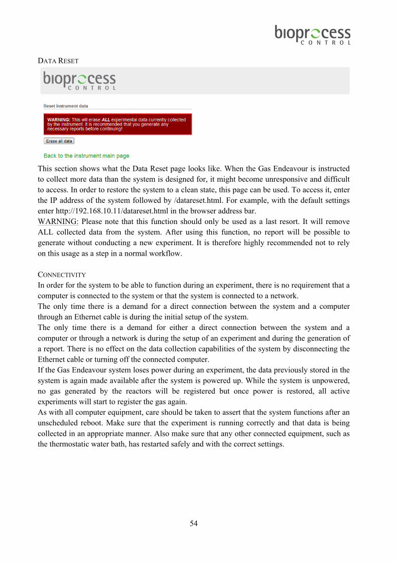
DATA RESET
This section shows what the Data Reset page looks like. When the Gas Endeavour is instructed to collect more data than the system is designed for, it might become unresponsive and difficult to access. In order to restore the system to a clean state, this page can be used. To access it, enter the IP address of the system followed by /datareset.html. For example, with the default settings enter http://192.168.10.11/datareset.html in the browser address bar. WARNING: Please note that this function should only be used as a last resort. It will remove ALL collected data from the system. After using this function, no report will be possible to generate without conducting a new experiment. It is therefore highly recommended not to rely on this usage as a step in a normal workflow. CONNECTIVITY In order for the system to be able to function during an experiment, there is no requirement that a computer is connected to the system or that the system is connected to a network. The only time there is a demand for a direct connection between the system and a computer through an Ethernet cable is during the initial setup of the system. The only time there is a demand for either a direct connection between the system and a computer or through a network is during the setup of an experiment and during the generation of a report. There is no effect on the data collection capabilities of the system by disconnecting the Ethernet cable or turning off the connected computer. If the Gas Endeavour system loses power during an experiment, the data previously stored in the system is again made available after the system is powered up. While the system is unpowered, no gas generated by the reactors will be registered but once power is restored, all active experiments will start to register the gas again. As with all computer equipment, care should be taken to assert that the system functions after an unscheduled reboot. Make sure that the experiment is running correctly and that data is being collected in an appropriate manner. Also make sure that any other connected equipment, such as the thermostatic water bath, has restarted safely and with the correct settings.

55
SOFTWARE UPGRADE
Care should always be taken to keep the built-in software of the Gas Endeavour up to date. BPC will, from time to time, issue software updates that can be installed on the system through an easy procedure. These updates can contain both new features and bug fixes so it is imperative that, when an update is received, the system is updated at an appropriate time. In order to install an update issued by BPC, append “upgrade” after the # to the standard Gas Endeavour url visible in the address bar of the web browser. Example for a standard configured unit would be http://192.168.10.11/app.html#upgrade. This will display the software upgrade interface. Click on the “Choose File” button and select the .zip file sent by BPC. Note: Do not unzip this file and never make any changes to the files contained inside of it. Also, make sure that the filename does not include any parentheses. Some operating systems, such as Microsoft Windows, will sometimes append parentheses to filenames when the same file is downloaded more than once. If this is the case, remove the parentheses from the filenames before using it to upgrade the system. When the file has been properly selected, click on the “Upgrade software” button. During the upgrade process, make sure that the system is not restarted or otherwise loses power. This might result in a failed upgrade. If this happens, redo the entire upgrade process from the start. It is recommended to leave the Gas Endeavour to finish its upgrade for five minutes to ensure that everything has been installed appropriately. When the upgrade is completed, the system will restart, with all previous data and settings intact and ready for use. To verify that the upgrade has taken place, go to the system tab of the system and, in the top left corner, compare the stated software version number to the version number of the file issued by BPC. It is recommended that the software be upgraded between experiments with all cells set in "end experiment” mode. If it is upgraded during an experiment, there is a risk that the cell openings occurring after the upgrade are not registered by the system.

56
9.4 Troubleshooting This section deals with problems that might arise during the operation of the Gas Endeavour. The instrument is highly advanced and needs to be handled as such. This means that, from time to time, unintended events might occur or difficulties in handling the equipment might be experienced. It is the intention of this chapter to help minimizing the probability for such events to occur and provide advice on how to solve some of the most common problems, which can come up during system operation. FINDING THE GAS ENDEAVOUR ON THE INTERNAL NETWORK If there is a problem of locating the assigned IP address of the Gas Endeavour after connecting it to the Internal network using automatic IP settings, there are few ways of manually detecting the unit. (Note: This does not apply if you have set up the instrument to be used via a direct the shielded Ethernet cable connection from a computer to the Gas Endeavour instrument). Due to the different ways networks can be setup, there is no way to guarantee that these steps will work. They should thus not be seen as replacements for contacting the local IT department (which is the recommended way of obtaining the IP address of the instrument). Instead they can assist if contacting the IT department is not feasible. These instructions are meant for the Microsoft Windows operating systems. USING AN EXTERNAL TOOL (IP TOOLS) Start by entering the following address: http://www.softpedia.com/get/Network-Tools/Protocol-Analyzers-Sniffers/IP-Sniffer.shtml into the web browser to download the IP Sniffer tool. After downloading the file, unzip it to a suitable location and enter the directory created. There, a file named iptools.exe should be available. Start the program and in the main window by selecting Tools -> ARP -> ARP Scan / MAC to IP on the top toolbar. A new window will appear. In the subnet field, there will be a pre-defined value. Usually, this will be the appropriate value for the network the Gas Endeavour is connected to. If the value here should be changed to reflect the internal network address assigned to new systems, do so. The program will now display a list of IPv4 addresses with associated Ethernet MAC hardware addresses. Check if any of these addresses match the “Ethernet MAC hardware address” associated with the Gas Endeavour instrument (printed on the back of the instrument). If a match is found, enter this address into a web browser to access the Gas Endeavour unit. USING THE COMMAND PROMPT IN WINDOWS Start the windows command prompt via the Windows start menu. This is usually located in All Programs / Accessories / Command Prompt. At the command prompt, write “arp –a” (without the quotation marks) and press enter. This will generate a list of the IP addresses currently in the arp cache. Check if any of the values located under “Physical Address” match the “Ethernet MAC hardware address” associated to the new Gas Endeavour Instrument. If a match is found, enter this address into a web browser to access the Gas Endeavour unit. If none of these addresses match the “Ethernet MAC hardware address” of the unit, the next step is to update the arp cache by issuing a broadcast ping to your local network. First, find out what

57
the IP address of the currently used computer is by writing “ipconfig” (without the quotation marks) in the command prompt and pressing enter. Find the section that starting with “IPv4 Address”. Next to it, a four-block number should be visible, similar in style to 192.168.0.1. If there are several IPv4 sections, this means there is more than one network card active in the computer and care needs to be taken to choose the one representing the internal network that the computer and the Gas Endeavour are connected to. After finding the mentioned IPv4 field, the subnet mask of the network needs to be determined. This should be located below the IPv4 field and be similar in style to 255.255.255.0. To determine the broadcast IP of the internal network, combine the IPv4 address and the subnet mask. Where the subnet mask indicates 255, retain the original field in the IPv4 address and where the subnet mask indicates something else, substitute that field in the IPv4 address for 255. In the previous example, that gives 192.168.0.1 and 255.255.255.0 and thus the broadcast address becomes 192.168.0.255. Next, in the command prompt, write “ping 192.168.0.255” (without the quotation marks and substituting the broadcast address for the one relevant to the network, calculated as described in the previous step). Wait for the program to run its course (this should take less than a few minutes). Write in the command prompt “arp –a” (without the quotation marks) and check the output. Try to match the Gas Endeavour Ethernet MAC hardware address to one of the fields and check what IP it is associated with. If a match is found, enter this address into a web browser to access the Gas Endeavour unit. Depending on the internal network setup, the correct Ethernet MAC hardware address will not be reported. Compare the results from the last “arp –a” to the first “arp –a” actions performed and check if any new IP addresses have shown up. If such addresses are identified, manually introduce them one by one into a web browser to verify if any of them can be connected to the Gas Endeavour unit. UNRESPONSIVE SYSTEM If the Gas Endeavour is used for collecting more data than is advisable, the system might become slow and unresponsive. It might become difficult to generate reports and change settings. It is thus highly recommended not to exceed the recommended gas production as, in some cases, it can render the collected data completely inaccessible. During this time, the page for the system might still appear to load but no changes will take effect. In order to determine if the system is properly loaded or if the system is unresponsive, go to the systems tab and look at the “flow cell volumes” fields. While the system is in a non-responsive state, these values will be displayed as “10”. Once the system is ready, these values will be updated to the values calibrated into the system by BPC. If Google Chrome is being used, it might, from time to time, show a dialog box asking if it should keep trying or if it should stop the page. This is due to Google Chrome assuming that the delay is due to a faulty executed program. This is not the case. The delay is because of the very

58
large amount of data accumulated. If using other web browsers, a dialog choice might not be presented and the web browser will simply stop executing the program, thus making it impossible to properly access the system. BPC always recommends using Google Chrome with the Gas Endeavour. After the system has loaded properly, the report should be possible to generate. As soon as this is done, the running experiments containing large sets of data should be cleared and a new experiment should be started. This does not, however, mean that the system cannot be used to analyse large data sets. The procedure to do so is to run the experiment up until the recommended limit of the system, generate a report and save it, clear the cells and continue. This procedure is then repeated until the full experiment has been finished. After this, the individual reports need to be combined and care taken to assure that the data is combined in an appropriate way. If the system becomes completely unresponsive and it is not possible to access the data the regular way, two options remain. If the data can be considered forfeitable, i.e. it is only for a short time period and the loss is not considered to have too large of an effect on the end results, the data can be completely cleared by using the built in function referred to under the head line “Data Reset” in chapter 9. This will make it possible to use the system again without affecting any of the network settings. Please note that the reset function on the back of the unit should NOT be used for this. The reset function on the back of the unit only resets the network settings and leaves the data intact. If the data is considered high value, it is possible for BPC to access the raw data of the system. Raw data is defined as the time when a flow cell opened as well as the associated temperature and pressure. If internet access is given (to BPC) to the system IP (port 80 and port 22), this raw data can be extracted and the system can also be reset. Please note that this should not be viewed as a solution taken lightly. The raw data, while in itself useful, needs to later on be analysed by the customer. The raw data does not take into account such features built into the Gas Endeavour report generation function such normalization, calibration of the flow cells, flush gas calculations and so forth.

59
10 MAINTENANCE
CLEAN THE EQUIPMENT REACTORS Use a bottlebrush and washing-up liquid (detergent) to clean the inside and outside of the reactors. Rinse well with water. Autoclaving the grey plastic stoppers and their stirrers works fine, but only after disconnecting the motors. Note: The motor and its holder must not be autoclaved. The same goes for the blue rubber stoppers with metal tubes and their stirrers, which contain plastic and rubber parts, which are characterised by uncertain heat stability and are therefore not suitable for autoclaving. THERMOSTATIC WATER BATH If normal tap water is used, calcareous deposits may appear on the reactors, in the water bath and on the heating element. Periodical cleaning of the inside of the tank and the heating element with a solution of 10 to 20% hydrochloric acid or a solution of water and vinegar (acetic acid) is advised. Rinse with clean water afterwards.
Alcohol can be used for cleaning the stainless steel parts, and (with a cotton duster) for cleaning the plastic parts. GAS VOLUME MEASURING DEVICE Rinse with water after use. A soft brush can be used very gently if needed. Make sure that all the flow cells are in the correct position. The position can be checked by lifting the flow cell and making sure that the software registers the opening of the flow cell.

60
APPENDIX A GAS NORMALISATION CALCULATION IN GAS ENDEAVOUR
The values for the parameters of interest (i.e. gas flow rate, accumulated volume) might be with or without normalisation. For the second case, the values are normalized to standard conditions, i.e., converted to 0°C, 1 atm and no humidity (i.e., removing the water content and considering the dry gas). This is carried out applying the following equation (1): 𝑉! = 𝑓!,!×𝑓!×𝑉!"## (1) where 𝑉! is the normalised volume, 𝑓!,! is a factor considering the temperature and pressure of the gas, 𝑓! is a factor considering the water content of the gas and 𝑉!"## is the registered volume for a cell opening. Temperature and pressure The factor considering the temperature and pressure (𝑓!,!) is calculated using the ideal gas law assumed to describe the physical characteristics of the gas within the temperature and pressure ranges used in an anaerobic digestion (AD) related test. 𝑓!,! is calculated according to equation (2):
𝑓!,! = !!!!"#
× !!"#!!
= !"#.!" !!"#!!"#.!"
× !!"#!!.!!"!.!"
(2)
where 𝑇! and 𝑝! are the standard temperature (273.15 K or 0 °C) and the standard pressure (101.32 kPa or 1 atm) respectively, 𝑇!"#, 𝑡!"# and 𝑝!"# represent the temperature (in K or °C) and pressure of the gas generated in the reactor at ambient conditions. These values are obtained from the internal temperature and pressure sensors of Gas Endeavour and are updated for each cell opening. The pressure of the gas is the sum of the measured pressure (expressed in kPa) and a constant factor equal to 0.6 (pressure exerted by approximately 6 cm water column from the detection unit). Water vapour The factor considering the water content of the gas (𝑓!) is calculated using the Antoine equation which is assumed to provide a good approximate of the vapour pressure around atmospheric pressure and in the temperature interval from 0 to 100°C. 𝑓! is calculated according to equation (3):
𝑓! = 1− !!"#!!"#
= 1− !"!.!"#$! !"#$.!"
!"".!"#!!!"#
!"×(!!"#!!.!) (3)
In the equation above the vapour pressure of the gas is assumed to be proportional with the gas volume (according to the ideal gas law). The volumetric fraction of the water is then equivalent to the pressure fraction obtained by dividing the water vapour pressure with the total pressure. The fraction of dry gas can then be calculated by removing the fraction of water from the wet gas. The values for the Antoine constants may be obtained from the Dortmund data bank (http://www.ddbst.com). Please note that the vapour pressure (i.e., 𝑝!"#) is calculated in mbar

61
units and the digester gas pressure (i.e., 𝑝!"#) is expressed in kPa, also considering the pressure exerted by the water column (approx. 6 cm) of the detection unit. In conclusion, the gas production is continuously registered and normalised by Gas Endeavour with real-time temperature and pressure compensation, according to equation (4) (derived from the equations (1)-(3)):
𝑉!,! =!"#.!"
!!"#,!!!"#.!" × (!!"#,!!!.!)
!"!.!" × 1− !"
!.!"#$! !"#$.!"!"".!"#!!!"#,!
!"×(!!"#,!!!.!)×𝑉!"## (4)
The accumulated volume reported by Gas Endeavour is calculated by summing up the cell volume for each cell opening. Each added volume is adjusted for pressure, temperature, and water vapour according to equation (5):
𝑉!"",! = 𝑉!"",!!! +!"#.!"
!!"#,!!!"#.!" × (!!"#,!!!.!)
!"!.!" × 1− !"
!.!"#$! !"#$.!"!"".!"#!!!"#,!
!"×(!!"#,!!!.!)×𝑉!"## (5)

62
APPENDIX B GAS ANALYSIS BY SELECTIVE CHEMICAL ABSORPTION IN GAS ENDEAVOUR
If Gas Endeavour is used in a specific application where there is a demand not only for measuring gas flow and volume, but also gas composition analysis, then it is recommended to use gas-traps. The quantitative composition of gas mixtures could be determined either i) directly, by measuring a certain physical property (e.g. ultraviolet or infrared absorption, conductivity), or ii) indirectly, after separating the components.
i) For direct measurements, gas sampling units have to be inserted into the system (e.g. 5 cm distance from the bioreactor), as explained in Chapter 4. Pre-Commissioning. The (collected) samples are either measured on-line with the help of (micro)sensors (e.g. CH4, CO2, H2, O2, N2O, NO, etc.) or off-line for example by gas chromatography.
ii) In most of the cases the gas mixtures are analysed after separation by selective chemical absorption using a gas trap unit and the remaining components are measured volumetrically with the help of Gas Endeavour.
The reactors from Gas Endeavour can be connected without/with gas absorption unit to measure the total gas production or only the gas of interest. The gas absorption unit is optional; it is not delivered together with the standard Gas Endeavour system. The dimension of the unit is: 44×30×6 cm.

63
Gas Absorption Unit (included parts) 1) Plastic stoppers with 2 tubes (15 st) 2) Plastic screw cap with holes (15 st) 3) Glass bottle 100 ml (15 st) 4) Bottle holder for 15 glass bottles For many applications, the gas components are separated by selective absorption in chemical solutions. Selective absorbents for the most important gases are listed in the table presented below. Table. Example of absorption reagents for several important gases Gas Chemical Absorbent Solution Carbon dioxide 10 to 40% potassium hydroxide
10 to 40% sodium hydroxide Hydrogen sulphide 10 to 36% potassium hydroxide
10 to 32% sodium hydroxide Cadmium chloride
Oxygen Alkaline pyrogallol Alkaline oxyhydroquinone Alkaline Na2S2O4 Sodium dithionite & sodium anthraquinone-ß-sulphonate Copper (I) chloride & ammonia Hydrochloric solution of copper (I) chloride Chromium (II) chloride
Carbon monoxide Copper (I) chloride Silver (I) oxide
Ammonia Water Standard acids Oxalic acid
Sulphur dioxide Hydrogen peroxide Potassium permanganate solution
Nitrogen dioxide Sulphanilic acid Naphthylamine
Nitrogen monooxide Iron (II) sulphate & sulphuric acid Acidic potassium permanganate solution
Hydrogen Colloidal palladium The individual gases are absorbed in absorption reagents, which are solutions of various substances. Good absorption reagents must fulfil a number of conditions:
i) The chemical reaction on which the absorption is based must be sufficiently fast; ii) The absorption must be selective; iii) The absorption capacity, i.e. the ability to absorb certain gas component, must be
sufficiently large so that the chemical reagent is not exhausted too rapidly.

64
For example, if the composition of a gas mixture containing H2, CO2, O2, and CO has to be analysed, then the gas sample has to successively pass into a solution of sodium or potassium hydroxide to absorb carbon dioxide, a solution of pyrogallic acid in sodium hydroxide to absorb oxygen and finally, a solution of cuprous chloride to absorb carbon monoxide. By measuring the total volume of gas as well as the reduction in volume after each step, it will be possible to calculate the percentage of each constituent in the gas mixture.
Equipment description (Design/Function) In the Gas absorption unit, the raw gas produced in each test vessel passes through an individual vial containing an absorbent of interest. Several gas fractions, such CO2, H2S, O2 could be retained by chemical interaction with the absorbent, only allowing gases of interest to pass through to the Gas Volume Measuring Device. When the gas absorption unit is used, preparing the reactors for start up follows the procedure described in Chapter 8. Operation, and then the additional steps presented below:
e) Cut 15 pieces of Tygon® tubing sufficiently in length to connect one of the small tubes on top of the plastic lids of each reactor to one connection on the plastic lid of the corresponding bottle for gas absorption.
f) Couple the second plastic connection on the lid of the gas absorption bottles to the corresponding tubing connector on the connection block located on the back of the Gas Endeavour. Repeat the procedure for each test vessel.

65
APPENDIX C LICENSES FOR THE OPEN SOURCE SOFTWARE ON GAS ENDEAVOUR
Not all software on the Gas Endeavour is licensed in a way that allows copying, modification, distribution, etc. This chapter should not be seen as granting any extra permission not demanded by the original license. Only the software specified in this chapter adheres to the specific licenses listed. Mongoose Web Server MIT License Copyright (c) 2004-2010 Sergey Lyubka Permission is hereby granted, free of charge, to any person obtaining a copy of this software and associated documentation files (the "Software"), to deal in the Software without restriction, including without limitation the rights to use, copy, modify, merge, publish, distribute, sublicense, and/or sell copies of the Software, and to permit persons to whom the Software is furnished to do so, subject to the following conditions:
• The above copyright notice and this permission notice shall be included in all copies or substantial portions of the Software.
• THE SOFTWARE IS PROVIDED "AS IS", WITHOUT WARRANTY OF ANY KIND, EXPRESS OR IMPLIED, INCLUDING BUT NOT LIMITED TO THE WARRANTIES OF MERCHANTABILITY, FITNESS FOR A PARTICULAR PURPOSE AND NONINFRINGEMENT. IN NO EVENT SHALL THE AUTHORS OR COPYRIGHT HOLDERS BE LIABLE FOR ANY CLAIM, DAMAGES OR OTHER LIABILITY, WHETHER IN AN ACTION OF CONTRACT, TORT OR OTHERWISE, ARISING FROM, OUT OF OR IN CONNECTION WITH THE SOFTWARE OR THE USE OR OTHER DEALINGS IN THE SOFTWARE.
jQuery.tmpl/jQuery.BlockUI Copyright (c) 2011 John Resig, http://jquery.com/ Permission is hereby granted, free of charge, to any person obtaining a copy of this software and associated documentation files (the "Software"), to deal in the Software without restriction, including without limitation the rights to use, copy, modify, merge, publish, distribute, sublicense, and/or sell copies of the Software, and to permit persons to whom the Software is furnished to do so, subject to the following conditions:
• The above copyright notice and this permission notice shall be included in all copies or substantial portions of the Software.
• THE SOFTWARE IS PROVIDED "AS IS", WITHOUT WARRANTY OF ANY KIND, EXPRESS OR IMPLIED, INCLUDING BUT NOT LIMITED TO THE WARRANTIES OF MERCHANTABILITY, FITNESS FOR A PARTICULAR PURPOSE AND NONINFRINGEMENT. IN NO EVENT SHALL THE AUTHORS OR COPYRIGHT HOLDERS BE LIABLE FOR ANY CLAIM, DAMAGES OR OTHER LIABILITY,

66
WHETHER IN AN ACTION OF CONTRACT, TORT OR OTHERWISE, ARISING FROM, OUT OF OR IN CONNECTION WITH THE SOFTWARE OR THE USE OR OTHER DEALINGS IN THE SOFTWARE.
jQuery.Caret Copyright (c) 2010 C. F., Wong, http://jquery-plugin.buss.hk/ Permission is hereby granted, free of charge, to any person obtaining a copy of this software and associated documentation files (the "Software"), to deal in the Software without restriction, including without limitation the rights to use, copy, modify, merge, publish, distribute, sublicense, and/or sell copies of the Software, and to permit persons to whom the Software is furnished to do so, subject to the following conditions:
• The above copyright notice and this permission notice shall be included in all copies or substantial portions of the Software.
• THE SOFTWARE IS PROVIDED "AS IS", WITHOUT WARRANTY OF ANY KIND, EXPRESS OR IMPLIED, INCLUDING BUT NOT LIMITED TO THE WARRANTIES OF MERCHANTABILITY, FITNESS FOR A PARTICULAR PURPOSE AND NONINFRINGEMENT. IN NO EVENT SHALL THE AUTHORS OR COPYRIGHT HOLDERS BE LIABLE FOR ANY CLAIM, DAMAGES OR OTHER LIABILITY, WHETHER IN AN ACTION OF CONTRACT, TORT OR OTHERWISE, ARISING FROM, OUT OF OR IN CONNECTION WITH THE SOFTWARE OR THE USE OR OTHER DEALINGS IN THE SOFTWARE.
jQuery.IPAddress / jQuery.Timer The MIT License Copyright (c) <year> <copyright holders> Permission is hereby granted, free of charge, to any person obtaining a copy of this software and associated documentation files (the "Software"), to deal in the Software without restriction, including without limitation the rights to use, copy, modify, merge, publish, distribute, sublicense, and/or sell copies of the Software, and to permit persons to whom the Software is furnished to do so, subject to the following conditions:
• The above copyright notice and this permission notice shall be included in all copies or substantial portions of the Software.
• THE SOFTWARE IS PROVIDED "AS IS", WITHOUT WARRANTY OF ANY KIND, EXPRESS OR IMPLIED, INCLUDING BUT NOT LIMITED TO THE WARRANTIES OF MERCHANTABILITY, FITNESS FOR A PARTICULAR PURPOSE AND NONINFRINGEMENT. IN NO EVENT SHALL THE AUTHORS OR COPYRIGHT HOLDERS BE LIABLE FOR ANY CLAIM, DAMAGES OR OTHER LIABILITY, WHETHER IN AN ACTION OF CONTRACT, TORT OR OTHERWISE, ARISING FROM, OUT OF OR IN CONNECTION WITH THE SOFTWARE OR THE USE OR OTHER DEALINGS IN THE SOFTWARE.
67
Downloadify Downloadify: Client Side File Creation JavaScript + Flash Library Copyright (c) 2009 Douglas C. Neiner Permission is hereby granted, free of charge, to any person obtaining a copy of this software and associated documentation files (the "Software"), to deal in the Software without restriction, including without limitation the rights to use, copy, modify, merge, publish, distribute, sublicense, and/or sell copies of the Software, and to permit persons to whom the Software is furnished to do so, subject to the following conditions:
• The above copyright notice and this permission notice shall be included in all copies or substantial portions of the Software.
• THE SOFTWARE IS PROVIDED "AS IS", WITHOUT WARRANTY OF ANY KIND, EXPRESS OR IMPLIED, INCLUDING BUT NOT LIMITED TO THE WARRANTIES OF MERCHANTABILITY, FITNESS FOR A PARTICULAR PURPOSE AND NONINFRINGEMENT. IN NO EVENT SHALL THE AUTHORS OR COPYRIGHT HOLDERS BE LIABLE FOR ANY CLAIM, DAMAGES OR OTHER LIABILITY, WHETHER IN AN ACTION OF CONTRACT, TORT OR OTHERWISE, ARISING FROM, OUT OF OR IN CONNECTION WITH THE SOFTWARE OR THE USE OR OTHER DEALINGS IN THE SOFTWARE.
960 Grid System Copyright (c) 2008 Nathan Smith, http://960.gs/ Permission is hereby granted, free of charge, to any person obtaining a copy of this software and associated documentation files (the "Software"), to deal in the Software without restriction, including without limitation the rights to use, copy, modify, merge, publish, distribute, sublicense, and/or sell copies of the Software, and to permit persons to whom the Software is furnished to do so, subject to the following conditions:
• The above copyright notice and this permission notice shall be included in all copies or substantial portions of the Software.
• THE SOFTWARE IS PROVIDED "AS IS", WITHOUT WARRANTY OF ANY KIND, EXPRESS OR IMPLIED, INCLUDING BUT NOT LIMITED TO THE WARRANTIES OF MERCHANTABILITY, FITNESS FOR A PARTICULAR PURPOSE AND NONINFRINGEMENT. IN NO EVENT SHALL THE AUTHORS OR COPYRIGHT HOLDERS BE LIABLE FOR ANY CLAIM, DAMAGES OR OTHER LIABILITY, WHETHER IN AN ACTION OF CONTRACT, TORT OR OTHERWISE, ARISING FROM, OUT OF OR IN CONNECTION WITH THE SOFTWARE OR THE USE OR OTHER DEALINGS IN THE SOFTWARE.

68
jQuery.flot Copyright (c) 2007-2009 IOLA and Ole Laursen Permission is hereby granted, free of charge, to any person obtaining a copy of this software and associated documentation files (the "Software"), to deal in the Software without restriction, including without limitation the rights to use, copy, modify, merge, publish, distribute, sublicense, and/or sell copies of the Software, and to permit persons to whom the Software is furnished to do so, subject to the following conditions:
• The above copyright notice and this permission notice shall be included in all copies or substantial portions of the Software.
• THE SOFTWARE IS PROVIDED "AS IS", WITHOUT WARRANTY OF ANY KIND, EXPRESS OR IMPLIED, INCLUDING BUT NOT LIMITED TO THE WARRANTIES OF MERCHANTABILITY, FITNESS FOR A PARTICULAR PURPOSE AND NONINFRINGEMENT. IN NO EVENT SHALL THE AUTHORS OR COPYRIGHT HOLDERS BE LIABLE FOR ANY CLAIM, DAMAGES OR OTHER LIABILITY, WHETHER IN AN ACTION OF CONTRACT, TORT OR OTHERWISE, ARISING FROM, OUT OF OR IN CONNECTION WITH THE SOFTWARE OR THE USE OR OTHER DEALINGS IN THE SOFTWARE.
Excanvas Apache License Version 2.0, January 2004, http://www.apache.org/licenses/ TERMS AND CONDITIONS FOR USE, REPRODUCTION, AND DISTRIBUTION 1. Definitions. "License" shall mean the terms and conditions for use, reproduction, and distribution as defined by Sections 1 through 9 of this document. "Licensor" shall mean the copyright owner or entity authorized by the copyright owner that is granting the License. "Legal Entity" shall mean the union of the acting entity and all other entities that control, are controlled by, or are under common control with that entity. For the purposes of this definition, "control" means (i) the power, direct or indirect, to cause the direction or management of such entity, whether by contract or otherwise, or (ii) ownership of fifty per cent (50%) or more of the outstanding shares, or (iii) beneficial ownership of such entity. "You" (or "Your") shall mean an individual or Legal Entity exercising permissions granted by this License. "Source" form shall mean the preferred form for making modifications, including but not limited to software source code, documentation source, and configuration files. "Object" form shall mean any form resulting from mechanical transformation or translation of a Source form, including but not limited to compiled object code, generated documentation, and conversions to other media types.

69
"Work" shall mean the work of authorship, whether in Source or Object form, made available under the License, as indicated by a copyright notice that is included in or attached to the work (an example is provided in the Appendix below). "Derivative Works" shall mean any work, whether in Source or Object form, that is based on (or derived from) the Work and for which the editorial revisions, annotations, elaborations, or other modifications represent, as a whole, an original work of authorship. For the purposes of this License, Derivative Works shall not include works that remain separable from, or merely link (or bind by name) to the interfaces of, the Work and Derivative Works thereof. "Contribution" shall mean any work of authorship, including the original version of the Work and any modifications or additions to that Work or Derivative Works thereof, that is intentionally submitted to Licensor for inclusion in the Work by the copyright owner or by an individual or Legal Entity authorized to submit on behalf of the copyright owner. For the purposes of this definition, "submitted" means any form of electronic, verbal, or written communication sent to the Licensor or its representatives, including but not limited to communication on electronic mailing lists, source code control systems, and issue tracking systems that are managed by, or on behalf of, the Licensor for the purpose of discussing and improving the Work, but excluding communication that is conspicuously marked or otherwise designated in writing by the copyright owner as "Not a Contribution." "Contributor" shall mean Licensor and any individual or Legal Entity on behalf of whom a Contribution has been received by Licensor and subsequently incorporated within the Work. 2. Grant of Copyright License. Subject to the terms and conditions of this License, each Contributor hereby grants to You a perpetual, worldwide, non-exclusive, no-charge, royalty-free, irrevocable copyright license to reproduce, prepare Derivative Works of, publicly display, publicly perform, sublicense, and distribute the Work and such Derivative Works in Source or Object form. 3. Grant of Patent License. Subject to the terms and conditions of this License, each Contributor hereby grants to You a perpetual, worldwide, non-exclusive, no-charge, royalty-free, irrevocable (except as stated in this section) patent license to make, have made, use, offer to sell, sell, import, and otherwise transfer the Work, where such license applies only to those patent claims licensable by such Contributor that are necessarily infringed by their Contribution(s) alone or by combination of their Contribution(s) with the Work to which such Contribution(s) was submitted. If You institute patent litigation against any entity (including a cross-claim or counterclaim in a lawsuit) alleging that the Work or a Contribution incorporated within the Work constitutes direct or contributory patent infringement, then any patent licenses granted to You under this License for that Work shall terminate as of the date such litigation is filed. 4. Redistribution. You may reproduce and distribute copies of the Work or Derivative Works thereof in any medium, with or without modifications, and in Source or Object form, provided that You meet the following conditions: (a) You must give any other recipients of the Work or Derivative Works a copy of this License; and (b) You must cause any modified files to carry prominent notices stating that You changed

70
the files; and (c) You must retain, in the Source form of any Derivative Works that You distribute, all copyright, patent, trademark, and attribution notices from the Source form of the Work, excluding those notices that do not pertain to any part of the Derivative Works; and (d) If the Work includes a "NOTICE" text file as part of its distribution, then any Derivative Works that You distribute must include a readable copy of the attribution notices contained within such NOTICE file, excluding those notices that do not pertain to any part of the Derivative Works, in at least one of the following places: within a NOTICE text file distributed as part of the Derivative Works; within the Source form or documentation, if provided along with the Derivative Works; or, within a display generated by the Derivative Works, if and wherever such third-party notices normally appear. The contents of the NOTICE file are for informational purposes only and do not modify the License. You may add Your own attribution notices within Derivative Works that You distribute, alongside or as an addendum to the NOTICE text from the Work, provided that such additional attribution notices cannot be construed as modifying the License. You may add Your own copyright statement to Your modifications and may provide additional or different license terms and conditions for use, reproduction, or distribution of Your modifications, or for any such Derivative Works as a whole, provided Your use, reproduction, and distribution of the Work otherwise complies with the conditions stated in this License. 5. Submission of Contributions. Unless You explicitly state otherwise, any Contribution intentionally submitted for inclusion in the Work by You to the Licensor shall be under the terms and conditions of this License, without any additional terms or conditions. Notwithstanding the above, nothing herein shall supersede or modify the terms of any separate license agreement you may have executed with Licensor regarding such Contributions. 6. Trademarks. This License does not grant permission to use the trade names, trademarks, service marks, or product names of the Licensor, except as required for reasonable and customary use in describing the origin of the Work and reproducing the content of the NOTICE file. 7. Disclaimer of Warranty. Unless required by applicable law or agreed to in writing, Licensor provides the Work (and each Contributor provides its Contributions) on an "AS IS" BASIS, WITHOUT WARRANTIES OR CONDITIONS OF ANY KIND, either express or implied, including, without limitation, any warranties or conditions of TITLE, NON-INFRINGEMENT, MERCHANTABILITY, or FITNESS FOR A PARTICULAR PURPOSE. You are solely responsible for determining the appropriateness of using or redistributing the Work and assume any risks associated with Your exercise of permissions under this License. 8. Limitation of Liability. In no event and under no legal theory, whether in tort (including negligence), contract, or otherwise, unless required by applicable law (such as deliberate and grossly negligent acts) or agreed to in writing, shall any Contributor be liable to You for damages, including any direct, indirect, special, incidental, or consequential damages of any character arising as a result of this License or out of the use or inability to use the Work (including but not limited to damages for loss of goodwill, work stoppage, computer failure or

71
malfunction, or any and all other commercial damages or losses), even if such Contributor has been advised of the possibility of such damages. 9. Accepting Warranty or Additional Liability. While redistributing the Work or Derivative Works thereof, You may choose to offer, and charge a fee for, acceptance of support, warranty, indemnity, or other liability obligations and/or rights consistent with this License. However, in accepting such obligations, You may act only on Your own behalf and on Your sole responsibility, not on behalf of any other Contributor, and only if You agree to indemnify, defend, and hold each Contributor harmless for any liability incurred by, or claims asserted against, such Contributor by reason of your accepting any such warranty or additional liability. END OF TERMS AND CONDITIONS APPENDIX: How to apply the Apache License to your work. To apply the Apache License to your work, attach the following boilerplate notice, with the fields enclosed by brackets "[]" replaced with your own identifying information. (Don't include the brackets!) The text should be enclosed in the appropriate comment syntax for the file format. We also recommend that a file or class name and description of purpose be included on the same "printed page" as the copyright notice for easier identification within third-party archives. Copyright [yyyy] [name of copyright owner] Licensed under the Apache License, Version 2.0 (the "License"); you may not use this file except in compliance with the License. You may obtain a copy of the License at http://www.apache.org/licenses/LICENSE-2.0 Unless required by applicable law or agreed to in writing, software distributed under the License is distributed on an "AS IS" BASIS, WITHOUT WARRANTIES OR CONDITIONS OF ANY KIND, either express or implied. See the License for the specific language governing permissions and limitations under the License. Knockout The MIT License Copyright (c) <year> <copyright holders> Permission is hereby granted, free of charge, to any person obtaining a copy of this software and associated documentation files (the "Software"), to deal in the Software without restriction, including without limitation the rights to use, copy, modify, merge, publish, distribute, sublicense, and/or sell copies of the Software, and to permit persons to whom the Software is furnished to do so, subject to the following conditions:
• The above copyright notice and this permission notice shall be included in all copies or substantial portions of the Software.
• THE SOFTWARE IS PROVIDED "AS IS", WITHOUT WARRANTY OF ANY KIND, EXPRESS OR IMPLIED, INCLUDING BUT NOT LIMITED TO THE WARRANTIES OF MERCHANTABILITY, FITNESS FOR A PARTICULAR PURPOSE AND

72
NONINFRINGEMENT. IN NO EVENT SHALL THE AUTHORS OR COPYRIGHT HOLDERS BE LIABLE FOR ANY CLAIM, DAMAGES OR OTHER LIABILITY, WHETHER IN AN ACTION OF CONTRACT, TORT OR OTHERWISE, ARISING FROM, OUT OF OR IN CONNECTION WITH THE SOFTWARE OR THE USE OR OTHER DEALINGS IN THE SOFTWARE.
Busybox GNU GENERAL PUBLIC LICENSE Version 2, June 1991 Copyright (C) 1989, 1991 Free Software Foundation, Inc. 51 Franklin Street, Fifth Floor, Boston, MA 02110-1301, USA Everyone is permitted to copy and distribute verbatim copies of this license document, but changing it is not allowed. Preamble The licenses for most software are designed to take away your freedom to share and change it. By contrast, the GNU General Public License is intended to guarantee your freedom to share and change free software--to make sure the software is free for all its users. This General Public License applies to most of the Free Software Foundation's software and to any other program whose authors commit to using it. (Some other Free Software Foundation software is covered by the GNU Lesser General Public License instead.) You can apply it to your programs, too. When we speak of free software, we are referring to freedom, not price. Our General Public Licenses are designed to make sure that you have the freedom to distribute copies of free software (and charge for this service if you wish), that you receive source code or can get it if you want it, that you can change the software or use pieces of it in new free programs; and that you know you can do these things. To protect your rights, we need to make restrictions that forbid anyone to deny you these rights or to ask you to surrender the rights. These restrictions translate to certain responsibilities for you if you distribute copies of the software, or if you modify it. For example, if you distribute copies of such a program, whether gratis or for a fee, you must give the recipients all the rights that you have. You must make sure that they, too, receive or can get the source code. And you must show them these terms so they know their rights. We protect your rights with two steps: (1) copyright the software, and (2) offer you this license which gives you legal permission to copy, distribute and/or modify the software. Also, for each author's protection and ours, we want to make certain that everyone understands that there is no warranty for this free software. If the software is modified by someone else and passed on, we want its recipients to know that what they have is not the original, so that any problems introduced by others will not reflect on the original authors' reputations. Finally, any free program is threatened constantly by software patents. We wish to avoid the danger that redistributors of a free program will individually obtain patent licenses, in effect making the program proprietary. To prevent this, we have made it clear that any patent must be licensed for everyone's free use or not licensed at all. The precise terms and conditions for copying, distribution and modification follow.
73
TERMS AND CONDITIONS FOR COPYING, DISTRIBUTION AND MODIFICATION 0. This License applies to any program or other work which contains a notice placed by the copyright holder saying it may be distributed under the terms of this General Public License. The "Program", below, refers to any such program or work, and a "work based on the Program" means either the Program or any derivative work under copyright law: that is to say, a work containing the Program or a portion of it, either verbatim or with modifications and/or translated into another language. (Hereinafter, translation is included without limitation in the term "modification".) Each licensee is addressed as "you". Activities other than copying, distribution and modification are not covered by this License; they are outside its scope. The act of running the Program is not restricted, and the output from the Program is covered only if its contents constitute a work based on the Program (independent of having been made by running the Program). Whether that is true depends on what the Program does. 1. You may copy and distribute verbatim copies of the Program's source code as you receive it, in any medium, provided that you conspicuously and appropriately publish on each copy an appropriate copyright notice and disclaimer of warranty; keep intact all the notices that refer to this License and to the absence of any warranty; and give any other recipients of the Program a copy of this License along with the Program. You may charge a fee for the physical act of transferring a copy, and you may at your option offer warranty protection in exchange for a fee. 2. You may modify your copy or copies of the Program or any portion of it, thus forming a work based on the Program, and copy and distribute such modifications or work under the terms of Section 1 above, provided that you also meet all of these conditions:
a) You must cause the modified files to carry prominent notices stating that you changed the files and the date of any change.
b) You must cause any work that you distribute or publish, that in whole or in part contains or is derived from the Program or any part thereof, to be licensed as a whole at no charge to all third parties under the terms of this License.
c) If the modified program normally reads commands interactively when run, you must cause it, when started running for such interactive use in the most ordinary way, to print or display an announcement including an appropriate copyright notice and a notice that there is no warranty (or else, saying that you provide a warranty) and that users may redistribute the program under these conditions, and telling the user how to view a copy of this License. (Exception: if the Program itself is interactive but does not normally print such an announcement, your work based on the Program is not required to print an announcement.) These requirements apply to the modified work as a whole. If identifiable sections of that work are not derived from the Program, and can be reasonably considered independent and separate works in themselves, then this License, and its terms, do not apply to those sections when you distribute them as separate works. But when you distribute the same sections as part of a whole which is a work based on the Program, the distribution of the whole must be on the terms of this License, whose permissions for other licensees extend to the entire whole, and thus to each and every part regardless of who wrote it.

74
Thus, it is not the intent of this section to claim rights or contest your rights to work written entirely by you; rather, the intent is to exercise the right to control the distribution of derivative or collective works based on the Program. In addition, mere aggregation of another work not based on the Program with the Program (or with a work based on the Program) on a volume of a storage or distribution medium does not bring the other work under the scope of this License. 3. You may copy and distribute the Program (or a work based on it, under Section 2) in object code or executable form under the terms of Sections 1 and 2 above provided that you also do one of the following:
a) Accompany it with the complete corresponding machine-readable source code, which must be distributed under the terms of Sections 1 and 2 above on a medium customarily used for software interchange; or,
b) Accompany it with a written offer, valid for at least three years, to give any third party, for a charge no more than your cost of physically performing source distribution, a complete machine-readable copy of the corresponding source code, to be distributed under the terms of Sections 1 and 2 above on a medium customarily used for software interchange; or,
c) Accompany it with the information you received as to the offer to distribute corresponding source code. (This alternative is allowed only for non-commercial distribution and only if you received the program in object code or executable form with such an offer, in accord with Subsection b above.) The source code for a work means the preferred form of the work for making modifications to it. For an executable work, complete source code means all the source code for all modules it contains, plus any associated interface definition files, plus the scripts used to control compilation and installation of the executable. However, as a special exception, the source code distributed need not include anything that is normally distributed (in either source or binary form) with the major components (compiler, kernel, and so on) of the operating system on which the executable runs, unless that component itself accompanies the executable. If distribution of executable or object code is made by offering access to copy from a designated place, then offering equivalent access to copy the source code from the same place counts as distribution of the source code, even though third parties are not compelled to copy the source along with the object code. 4. You may not copy, modify, sublicense, or distribute the Program except as expressly provided under this License. Any attempt otherwise to copy, modify, sublicense or distribute the Program is void, and will automatically terminate your rights under this License. However, parties who have received copies, or rights, from you under this License will not have their licenses terminated so long as such parties remain in full compliance. 5. You are not required to accept this License, since you have not signed it. However, nothing else grants you permission to modify or distribute the Program or its derivative works. These actions are prohibited by law if you do not accept this License. Therefore, by modifying or distributing the Program (or any work based on the Program), you indicate your acceptance of this License to do so, and all its terms and conditions for copying, distributing or modifying the Program or works based on it.

75
6. Each time you redistribute the Program (or any work based on the Program), the recipient automatically receives a license from the original licensor to copy, distribute or modify the Program subject to these terms and conditions. You may not impose any further restrictions on the recipients' exercise of the rights granted herein. You are not responsible for enforcing compliance by third parties to this License. 7. If, as a consequence of a court judgment or allegation of patent infringement or for any other reason (not limited to patent issues), conditions are imposed on you (whether by court order, agreement or otherwise) that contradict the conditions of this License, they do not excuse you from the conditions of this License. If you cannot distribute so as to satisfy simultaneously your obligations under this License and any other pertinent obligations, then as a consequence you may not distribute the Program at all. For example, if a patent license would not permit royalty-free redistribution of the Program by all those who receive copies directly or indirectly through you, then the only way you could satisfy both it and this License would be to refrain entirely from distribution of the Program. If any portion of this section is held invalid or unenforceable under any particular circumstance, the balance of the section is intended to apply and the section as a whole is intended to apply in other circumstances. It is not the purpose of this section to induce you to infringe any patents or other property right claims or to contest validity of any such claims; this section has the sole purpose of protecting the integrity of the free software distribution system, which is implemented by public license practices. Many people have made generous contributions to the wide range of software distributed through that system in reliance on consistent application of that system; it is up to the author/donor to decide if he or she is willing to distribute software through any other system and a licensee cannot impose that choice. This section is intended to make thoroughly clear what is believed to be a consequence of the rest of this License. 8. If the distribution and/or use of the Program is restricted in certain countries either by patents or by copyrighted interfaces, the original copyright holder who places the Program under this License may add an explicit geographical distribution limitation excluding those countries, so that distribution is permitted only in or among countries not thus excluded. In such case, this License incorporates the limitation as if written in the body of this License. 9. The Free Software Foundation may publish revised and/or new versions of the General Public License from time to time. Such new versions will be similar in spirit to the present version, but may differ in detail to address new problems or concerns. Each version is given a distinguishing version number. If the Program specifies a version number of this License which applies to it and "any later version", you have the option of following the terms and conditions either of that version or of any later version published by the Free Software Foundation. If the Program does not specify a version number of this License, you may choose any version ever published by the Free Software Foundation. 10. If you wish to incorporate parts of the Program into other free programs whose distribution conditions are different, write to the author to ask for permission. For software, which is copyrighted by the Free Software Foundation, write to the Free Software Foundation; we sometimes make exceptions for this. Our decision will be guided by the two goals of preserving

76
the free status of all derivatives of our free software and of promoting the sharing and reuse of software generally. NO WARRANTY 11. BECAUSE THE PROGRAM IS LICENSED FREE OF CHARGE, THERE IS NO WARRANTY FOR THE PROGRAM, TO THE EXTENT PERMITTED BY APPLICABLE LAW. EXCEPT WHEN OTHERWISE STATED IN WRITING THE COPYRIGHT HOLDERS AND/OR OTHER PARTIES PROVIDE THE PROGRAM "AS IS" WITHOUT WARRANTY OF ANY KIND, EITHER EXPRESSED OR IMPLIED, INCLUDING, BUT NOT LIMITED TO, THE IMPLIED WARRANTIES OF MERCHANTABILITY AND FITNESS FOR A PARTICULAR PURPOSE. THE ENTIRE RISK AS TO THE QUALITY AND PERFORMANCE OF THE PROGRAM IS WITH YOU. SHOULD THE PROGRAM PROVE DEFECTIVE, YOU ASSUME THE COST OF ALL NECESSARY SERVICING, REPAIR OR CORRECTION. 12. IN NO EVENT UNLESS REQUIRED BY APPLICABLE LAW OR AGREED TO IN WRITING WILL ANY COPYRIGHT HOLDER, OR ANY OTHER PARTY WHO MAY MODIFY AND/OR REDISTRIBUTE THE PROGRAM AS PERMITTED ABOVE, BE LIABLE TO YOU FOR DAMAGES, INCLUDING ANY GENERAL, SPECIAL, INCIDENTAL OR CONSEQUENTIAL DAMAGES ARISING OUT OF THE USE OR INABILITY TO USE THE PROGRAM (INCLUDING BUT NOT LIMITED TO LOSS OF DATA OR DATA BEING RENDERED INACCURATE OR LOSSES SUSTAINED BY YOU OR THIRD PARTIES OR A FAILURE OF THE PROGRAM TO OPERATE WITH ANY OTHER PROGRAMS), EVEN IF SUCH HOLDER OR OTHER PARTY HAS BEEN ADVISED OF THE POSSIBILITY OF SUCH DAMAGES. END OF TERMS AND CONDITIONS Acquiring Source Code All the source code for the software mentioned above, that stipulates that this condition needs to be met, can be acquired from Bioprocess Control upon request to [email protected].