Embed Size (px)
Citation preview

CenturionGuided RadarCGR Series
Manual
Sultan Sonar Manual Rev 1.0
A Higher Level of Performance
www.hawkmeasure.comFor more information, please visit >
2
Table of ContentsCenturion Guided Radar
Contents
Overview 3
Principle of Operation 3
Function 3
Primary Areas of Application 3
Wiring & Dimensions 4
Wiring Compartment 4
Flexible Probe 4
Housing 4
Rigid Probe 4
Probe C35 (Interface) 4
Safety Instructions 5
CGR2 Series Wiring in Hazardous Locations 5
Installation Guide 6
Placement Requirements 6
Connection Requirements - Metallic Vessels 7
Nozzle Mounting 7
Mounting 8
Minimum Clearance 8
Forces On The Probe 9
Powering The Unit For The First Time 10
Setup Procedure 11
1. Setup Parameters 11
2. Advanced Parameters 12
3. Sensitivity Calibration 13
Troubleshooting - via Controller Keypad 14
False Echo Elimination 14
Unit is reading deeper than actual level 16
Unit is measuring deeper than the length of the cable 16
Part Numbering 17
Centurion Guided Radar 17
Flange Table 18
Specifications 19

Centurion Guided RadarOverview
3
Principle of Operation
Single ProbeMicrowave pulses are transmitted along a cable or probe to the product being measured. At the point where
the wave meets the product surface it is reflected by the product. The unit automatically calculates the
distance to the pulse reflection using time of flight & time expansion. The intensity of the reflection depends
on the dielectric constant of the product. The instrument measures the time between emission and reception
of the signal which is proportional to the distance.
Dual ProbeThe unique patented HAWK Dual probe solution uses specially developed signal mapping techniques.
The combination of HAWK’s hardware and software give an accurate and consistent output for interfaces
level measurement.
Function
The HAWK range of Guided Radar products are ideal for the measurement of liquids, sludge, powders and granules to a range of 18m for level and interface. This technology is not affected by pressure, temperature, viscosity, vacuum, foam, dust, changes in dielectric constant or coating of the probe.
Primary Areas of Application
• Chemicals
• Petrochemicals
• Cement
• Building Aggregates
• Energy
• Food & Beverages
• Oil & Gas
• Pharmaceutical
• Pulp & Paper
• Wastewater
• Multiple Interface Measurement• IECEx Ex d [ia] ia IIC T6 Gb Ga• Up to 18m range (316L cable)• Simple setup• Auto-Calibration to any dielectric• Adjustable Sensitivity• Precise & continuous accuracy
• 2 wire loop• 4-20mA, 2x 4-20mA, HART, Foundation Fieldbus, Profibus PA • Protection class IP66• Measures extremely low dielectric (1.6)
• Programmable fail safe mode
Features

Wiring & Dimensions
4
Centurion Guided Radar
Flexible Probe
HousingWiring Terminal Compartment
110
109
152
87
L=
Det
erm
ine
by A
pplic
atio
n
Ex C
ABL
E G
LAN
DL1
= T
.B.D
.
4/8/16mm
D
(2.5
")
A B
E
63.0
Cab
le L
engt
h (m
m)
C
F
G
40.0
(1.5
”) mounting thread1 1/2" BSP or NPT
110
109
152
87
L=
Det
erm
ine
by A
pplic
atio
n
Ex C
ABL
E G
LAN
DL1
= T
.B.D
.
4/8/16mm
D
(2.5
")
A B
E
63.0
Cab
le L
engt
h (m
m)
C
F
G
40.0
(1.5
”) mounting thread1 1/2" BSP or NPT
Rigid Probe Probe C35 (Interface)
9
8
7
65 4
3
2
1
0+
-EMCGND
GND + - EMCGND

Safety InstructionsCenturion Guided Radar
5
Safety Instructions
For installation requirements for Hazardous Locations please refer to appropriate Safety Instruction document located at:
http://www.hawkmeasure.com/productdetail.asp?id=57
CGR2 Series Wiring in Hazardous Locations
Zone 1
Zone 1 or Zone 0
4-20mA current loopU = 14-28VDC
+-
EMC/Protective Ground
See terminal compartment wiring
987
NOTE: (Ref Safety Instructions Sect 10a)
Application of supply voltages above 28VDC will cause damage to the equipment.
Voltages less than the Um will not invalidate the type of protection.
Installation Guide
6
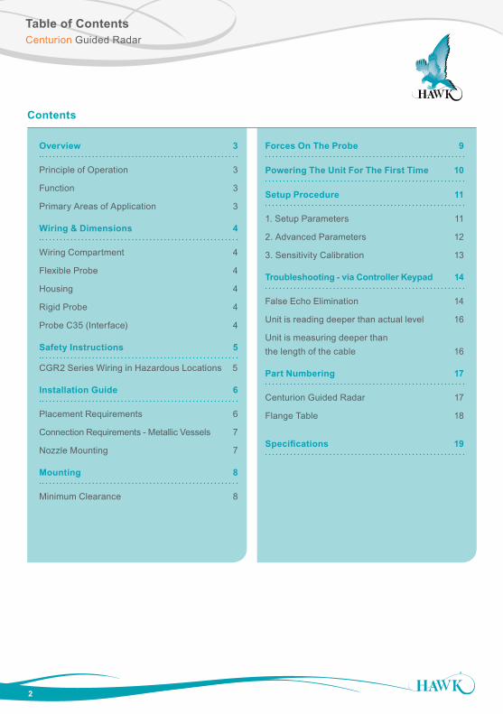
Placement Requirements
Centurion Guided Radar
Do NOT mount near infeed
Do NOT mount over or adjacent to any obstacles
Installation Guide
7
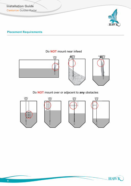
Connection Requirements - Metallic Vessels
The unit requires a metallic flange or sheet connected to the unit thread.
• Avoid mounting adjacent to internal structures • Probes should not contact metallic container walls or floors.
Centurion Guided Radar
Min 100mm
Nozzle
Metal flange
Metal flange
Interior VesselCeiling
Min 100mm
Nozzle
Metal flange
Metal flange
Interior VesselCeiling
Multiple segmented connection
If using thread multiple connection pieces for thread standard and size integration a metallic plate or flange of minimum recommended size should be at the lowest possible point of the mounting.
Min 100mm
Nozzle
Metal flange
Metal flange
Interior VesselCeiling
Nozzle Mounting
High Level
Avoid Narrow Nozzles
Minimum measurable distance can be affected by narrow nozzles. Conduct Digitisation and/or increase Blanking to a safe minimum distance for example: double nozzle height + 25% safe distance
Do NOT mount in long narrow nozzles
High Level
Mounting
8
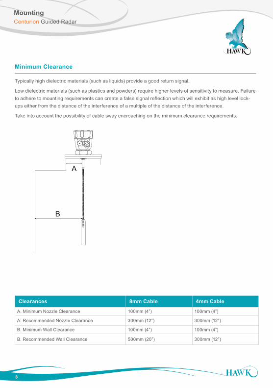
Minimum Clearance
Typically high dielectric materials (such as liquids) provide a good return signal.
Low dielectric materials (such as plastics and powders) require higher levels of sensitivity to measure. Failure to adhere to mounting requirements can create a false signal reflection which will exhibit as high level lock-ups either from the distance of the interference of a multiple of the distance of the interference.
Take into account the possibility of cable sway encroaching on the minimum clearance requirements.
Clearances 8mm Cable 4mm Cable
A. Minimum Nozzle Clearance 100mm (4”) 100mm (4”)
A: Recommended Nozzle Clearance 300mm (12”) 300mm (12”)
B. Minimum Wall Clearance 100mm (4”) 100mm (4”)
B. Recommended Wall Clearance 500mm (20”) 300mm (12”)
Centurion Guided Radar
A
B
Forces On The Probe
9
Centurion Guided Radar
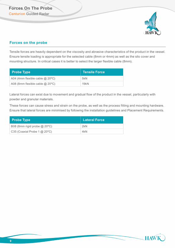
Probe Type Tensile Force
A04 (4mm flexible cable @ 20ºC) 5kN
A08 (8mm flexible cable @ 20ºC) 19kN
Probe Type Lateral Force
B08 (8mm rigid probe @ 20ºC) 2kN
C35 (Coaxial Probe 1 @ 20ºC) 4kN
Forces on the probe
Tensile forces are heavily dependent on the viscosity and abrasive characteristics of the product in the vessel. Ensure tensile loading is appropriate for the selected cable (8mm or 4mm) as well as the silo cover and mounting structure. In critical cases it is better to select the larger flexible cable (8mm).
Lateral forces can exist due to movement and gradual flow of the product in the vessel, particularly with powder and granular materials.
These forces can cause stress and strain on the probe, as well as the process fitting and mounting hardware. Ensure that lateral forces are minimised by following the installation guidelines and Placement Requirements.

Powering The Unit For The First Time
10
A. Confirm mounting is within recommended specifications.
B. Check the selected unit matches the required application specifications. For Hazardous Locations see appropriate safety instructions available at http://www.hawkmeasure.com
C. Check the wiring is correct and all connections are secure.
D. Apply power to the unit.
When power is applied the unit will start its normal load sequence. The following messages will cycle on the display.
Product Type Serial number Unit ID TDR Warming up
The unit may take up to 30 seconds to warm up, and then it will perform a scan to locate the level.
Centurion Guided Radar

Parameter Description Options
Display
Mode
Select default Display mode VolumeLevel%LevelSpace
Display Unit Adjust displayed measurement unit CentimetersMetresFeet Inches
Low Level Set Low Level (4mA) distance Adjustable
Hi Level Set High Level (20mA) distance Adjustable
Damping Set countdown for failsafe (seconds) Adjustable
Fail Mode Set Analogue failsafe output 3.50mA20.20mALastKnown4mA20.00mA
Setup Procedure
11
Centurion Guided Radar
In this operational state you can use the
Space2.622m
Matrl%74.0%
E: 0.4110.7%
S: 0.74V110.7%
buttons to navigate through and view unit diagnostics and other measurements.
Setting Setup Application ParametersThe Setup menu contains the basic parameters required to get the unit up and running. It is one of the three main menu options in the internal software.
B
A
C
A Blanking (non-measurable zone)
B Measurable Span (blanking to top of weight/end of cable)
C Weight (non measurable zone)
Setup
See ‘Measured Span Reference’
Measured Span Reference
1. Setup Parameters
Software Flow ChartTDR Revision 2
2.525Standard Operating Mode
LEVEL (m) Press2.525LEVEL (m)
20.0mA
mA diagnostic
2.525LEVEL (m)
Normal
Status NormalStatus: FailsafeStatus: Search
CAL
Main MenuSetupAdvancedAutoset
SetupDisplay ModeDisplay UnitHi LevelLow LevelDampingFail Mode
AdvancedCommsTrackingSensitivityDigitizeCal MountEcho SizeAnalogueFactry ResetDevice InfoLock CodeLanguage
Standard Operating Mode
Main Menu
2.525LEVEL (m)
Sens. 84
Sensitivity value
2.525LEVEL (m)
Echo distance & size
Echo d7.5 s1.5
2.525LEVEL (m)
ID 1
Device ID (For HART, FF, PA)
2.525LEVEL (m)
Tag xxxxxxx
Instrument Tag ID
AutoSetLow LevelHi LevelDigitize
Press & hold for 3 seconds & release button to access AutoSet
AutoSet - link to standard Low Level, High Level & Digitise
Setup Procedure
12
Centurion Guided Radar
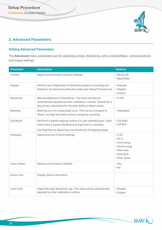
Setting Advanced Parameters
The Advanced menu parameters are for adjusting primary Sensitivity, echo controls/filters, communications and output settings.
2. Advanced Parameters
Parameter Description Options
Comms Adjust communication protocol settings. • Device ID• Baud Rate
Digitize Perform auto-Digitization of Sensitivity based on mounting and Dielectric of material touching the probe (see Setup Procedure A)
• Execute• Disable• Cancel
Sensitivity Manual adjustment of Sensitivity. This value will also be automatically adjusted by other calibration routines. Sensitivity is the primary adjustment for the units ability to detect media
• 0-100
Blanking Blanking is a non-measurable zone. This can be increased to ‘Blank’ out high level false echoes caused by mounting
• Adjustable
Cal Mount Performs a digital mapping routine of a user selected span. Used when there is signal interference at high level or mounting.
Use Digit Bias to adjust bias (cal sensitivity) of mapping range
• Cal Start • Cal End
Analogue Adjust and tune 4-20mA settings • 4-20• 20-4• 4mA tuning• 20mA tuning• Park 4mA• Park 8mA• Park 12mA
Factry Reset Restore unit to factory defaults • Yes• No
Device Info Display device information
Lock Code Adjust the peak Sensitivity cap. This value will be automatically adjusted by other calibration routines
• Disable• Enable
Setup ProcedureCenturion Guided Radar
13
Procedure A: Running Digitize while material is touching the probe
This procedure uses automatic procedure for sensitivity adjustment & mapping to calibrate the system based on the dielectric of the material touching the probe element and the mounting conditions.
This is the recommended calibration procedure for fastest and most accurate unit setup.
•Digitize is located in the Advanced menu.
3. Sensitivity Calibration
• Procedure A: Running Digitize while material is touching the probe• Procedure B: Using dielectric pre-sets• Procedure C: Manual Sensitivity Adjustment
Procedure B: Manual Sensitivity Adjustment
This procedure is an advanced method for calibrating the sensitivity of the system. This involves manually adjusting the sensitivity until the unit is measuring the length of the sensing element or to the depth of material touching the sensing element.
• The ‘Sensitivity’ parameter is located in ‘Adv Setup’
• You can press ‘CAL’ to fire test pulses. After each pulse the unit will return the signal strength and distance (depth) of the echo. You should aim for a signal strength of 2-2.5V. This may not be achievable with low dielectric materials.
Troubleshooting - via Controller KeypadCenturion Guided Radar
14
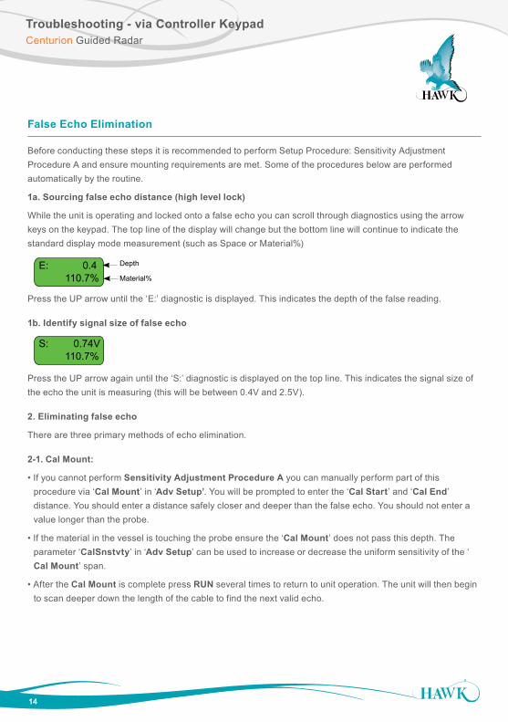
False Echo Elimination
Before conducting these steps it is recommended to perform Setup Procedure: Sensitivity Adjustment Procedure A and ensure mounting requirements are met. Some of the procedures below are performed automatically by the routine.
1a. Sourcing false echo distance (high level lock)
While the unit is operating and locked onto a false echo you can scroll through diagnostics using the arrow keys on the keypad. The top line of the display will change but the bottom line will continue to indicate the standard display mode measurement (such as Space or Material%)
Press the UP arrow until the ‘E:’ diagnostic is displayed. This indicates the depth of the false reading.
1b. Identify signal size of false echo
Press the UP arrow again until the ‘S:’ diagnostic is displayed on the top line. This indicates the signal size of the echo the unit is measuring (this will be between 0.4V and 2.5V).
2. Eliminating false echo
There are three primary methods of echo elimination.
2-1. Cal Mount:
• If you cannot perform Sensitivity Adjustment Procedure A you can manually perform part of this procedure via ‘Cal Mount’ in ‘Adv Setup’. You will be prompted to enter the ‘Cal Start’ and ‘Cal End’ distance. You should enter a distance safely closer and deeper than the false echo. You should not enter a value longer than the probe.
• If the material in the vessel is touching the probe ensure the ‘Cal Mount’ does not pass this depth. The parameter ‘CalSnstvty’ in ‘Adv Setup’ can be used to increase or decrease the uniform sensitivity of the ‘ Cal Mount’ span.
• After the Cal Mount is complete press RUN several times to return to unit operation. The unit will then begin to scan deeper down the length of the cable to find the next valid echo.
Space2.622m
Matrl%74.0%
E: 0.4110.7%
S: 0.74V110.7%
Depth
Material%
Space2.622m
Matrl%74.0%
E: 0.4110.7%
S: 0.74V110.7%

Troubleshooting - via Controller KeypadCenturion Guided Radar
15
2-2. Reduce Sensitivity: • Enter the ‘Adv Setup’ menu and scroll until you see ‘Sensitivity’ parameter. • Press CAL to edit. Use the DOWN arrow to reduce this value. • Pressing CAL will fire a test pulse and return the diagnostic data of the Signal size and E: distance. Fire several test pulses for a good sample size. • Reduce this value until the unit is no longer displaying the false echo while firing test pulses. • Press RUN to save and RUN again to return the unit to operating mode. • The unit will then begin to scan deeper down the length of the cable to find the next valid echo.
.
In Fig 1 you can see at 90% Sensitivity both false echoes and the correct level are considered valid targets by the unit. At 50% Sensitivity the only echo the unit will see is the correct level
3. Blanking & Span adjustment
• If the previous steps are unable to solve a high level lock up there will be a significant signal interference. Visually examine within the vessel for any objects near or touching the sensing element.
• Extend Blanking beyond the depth of the false echo and adjust High level so it is not within the blanked distance.
• Perform a 15 second power cycle, the unit will re-scan for the closest signal which beyond the Blanking distance.
• Attempt to perform Setup Procedure A, B or C if the unit does not locate the correct distance with the false echoes blanked out.
CorrectLevel
Distance
False Echoes
Sen
sitiv
ityR
ange
0%
100%
90%
50%
Fig 1
Troubleshooting - via Controller KeypadCenturion Guided Radar
16
Unit is reading deeper than actual level
This may occur in low dielectric applications where the cable weight returns a stronger echo than the measured material.
If you have used any other parameters such as ‘Cal Mount’ perform a Probe Reset.
Increase Sensitivity:
• Enter the ‘Adv Setup’ menu and scroll until you see ‘Sensitivity’ parameter.
• Press CAL to edit. Use the UP arrow to increase this value.
• Pressing CAL will fire a test pulse and return the diagnostic data of the Signal size and E: distance.
• Fire several test pulses for a good sample size.
• Increase this value until the unit is returning a strong (2-2.5V) Signal size from the false echo.
• Press RUN to save and RUN again to return the unit to operating mode.
• Perform a 15 second power cycle - when the unit re-starts it will begin a new scan over the entire probe to find the closest echo which passes the Threshold value.
Unit is measuring deeper than the length of the cable
• Press CAL and enter Unlock Code 196 and press CAL.
• Scroll through the main menus to locate ‘FactoryTDR’ menu.
• Press CAL to enter this menu.
• Scroll down to locate the ‘EmptDist’ parameter.
• This should be the length of the cable by factory default. If not, reduce this value to the correct length with a small additional margin (+250mm/12”). DO NOT ADJUST ANY OTHER PARAMETERS IN THIS MENU.
• Perform a 15 second power cycle - when the unit re-starts it will begin a new scan over the entire probe to find the closest echo which passes the Threshold value.
Part NumberingCenturion Guided Radar
17
1See flange selection table. Flange is selected as separate line item
Centurion Guided Radar
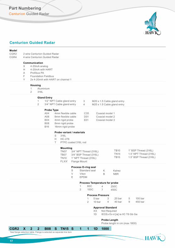
Model CGR2 2 wire Centurion Guided Radar CGR4 4 wire Centurion Guided Radar
Communication X 4-20mA analog H 4-20mA with HART A Profibus PA F Foundation Fieldbus Y 2x 4-20mA with HART on channel 1
Housing 1 Aluminium 2 316L
Gland Entry 1 1/2” NPT Cable gland entry 2 3/4” NPT Cable gland entry
Probe Type A04 4mm flexible cable A08 8mm flexible cable B04 4mm rigid probe B08 8mm rigid probe B16 16mm rigid probe
Probe variant / materials S 316L H HC-276 T PTFE coated 316L rod
Mounting TN07 3/4” NPT Thread (316L) TB07 3/4” BSP Thread (316L) TN10 1” NPT Thread (316L) FLXX1 Flange Mount
Process O-ring seal S Standard seal V Viton E EPDM
Process Temperature for probe 1 80C 2 150C
Process Pressure 1 5 bar 2 10 bar
Approval Standard XX Not Required 1D IECEx Ex d [ia] ia IIC T6 Gb Ga
Probe Length Probe length in cm (max 1800)
CGR2 X 2 2 B08 S TN15 S 1 1 1D 1000
C35 Coaxial model 1 D01 Coaxial model 2 E01 Coaxial model 3
TB10 1” BSP Thread (316L)TN15 1.5” NPT Thread (316L)TB15 1.5” BSP Thread (316L)
3 M20 x 1.5 Cable gland entry 4 M25 x 1.5 Cable gland entry
K Kalrez B NBR
4 250C7 450C
3 20 bar4 40 bar
5 100 bar9 450 bar
Part NumberingCenturion Guided Radar
18
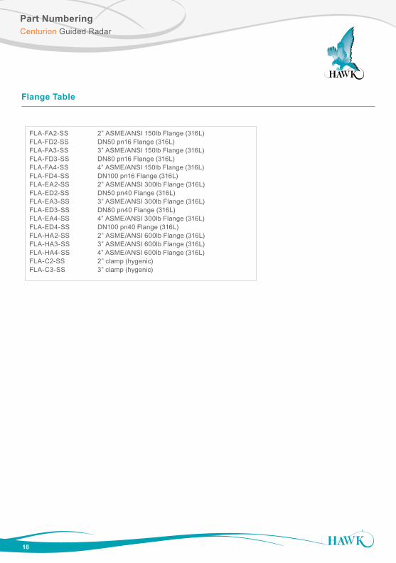
FLA-FA2-SS 2” ASME/ANSI 150lb Flange (316L)FLA-FD2-SS DN50 pn16 Flange (316L)FLA-FA3-SS 3” ASME/ANSI 150lb Flange (316L) FLA-FD3-SS DN80 pn16 Flange (316L)FLA-FA4-SS 4” ASME/ANSI 150lb Flange (316L) FLA-FD4-SS DN100 pn16 Flange (316L)FLA-EA2-SS 2” ASME/ANSI 300lb Flange (316L)FLA-ED2-SS DN50 pn40 Flange (316L)FLA-EA3-SS 3” ASME/ANSI 300lb Flange (316L)FLA-ED3-SS DN80 pn40 Flange (316L) FLA-EA4-SS 4” ASME/ANSI 300lb Flange (316L)FLA-ED4-SS DN100 pn40 Flange (316L)FLA-HA2-SS 2” ASME/ANSI 600lb Flange (316L)FLA-HA3-SS 3” ASME/ANSI 600lb Flange (316L)FLA-HA4-SS 4” ASME/ANSI 600lb Flange (316L)FLA-C2-SS 2” clamp (hygenic)FLA-C3-SS 3” clamp (hygenic)
Flange Table
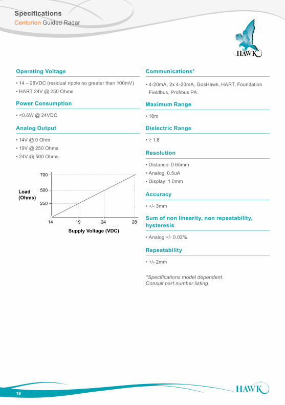
SpecificationsCenturion Guided Radar
19
Operating Voltage
• 14 – 28VDC (residual ripple no greater than 100mV)
• HART 24V @ 250 Ohms
Power Consumption
• <0.6W @ 24VDC
Analog Output
• 14V @ 0 Ohm
• 19V @ 250 Ohms
• 24V @ 500 Ohms
14 19 24 28
700
500
250
Load(Ohms)
Supply Voltage (VDC)
Communications*
• 4-20mA, 2x 4-20mA, GosHawk, HART, Foundation Fieldbus, Profibus PA.
Maximum Range
• 18m
Dielectric Range
• ≥ 1.6
Resolution
• Distance: 0.65mm
• Analog: 0.5uA
• Display: 1.0mm
Accuracy
• +/- 3mm
Sum of non linearity, non repeatability, hysteresis
• Analog +/- 0.02%
Repeatability
• +/- 2mm
*Specifications model dependent. Consult part number listing.

SpecificationsCenturion Guided Radar
Memory
• Non-Volatile (No backup battery required) >10 years data retention
Measurement Range of Electronics
• Min. 150mm
• Max. 18m
Operating Temperature (Electronics)
• -20ºC to +80ºC (-28 to +176ºF)
Process Pressure*
• -1 to 450 BAR
Process Temperature*
• -30ºC to +450ºC (-35ºF to +842ºF)
Display
• 4 line graphic display (128 x 64)
Approvals*
• IECEx Ex d [ia] ia IIC T6 Gb Ga
Probe Physical Load
• Max tensile load on 8mm cable: • 4 tonnes at 23ºC • 3 tonnes at 80ºC
• Max lateral force on C35 probe: • 4 kN
-20 0 80 100
40
20
0-1
Process Pressure
(Bar)
Process Temperature (Deg C)
Standard Unit
-20 0 80 100
40
20
0-1
Process Pressure
(Bar)
Process Temperature (Deg C)
Standard Unit
*Specifications model dependent. Consult part number listing
20
Hawk Measurement Systems(HeadOffice)15 - 17 Maurice Court Nunawading VIC 3131, AUSTRALIA
Phone: +61 3 9873 4750Fax: +61 3 9873 [email protected]
Hawk Measurement 96 Glenn StreetLawrence, MA 01843, USA
Phone: +1 888 HAWKLEVEL (1-888-429-5538)Phone: +1 978 304 3000Fax: +1 978 304 [email protected]
DO
C-C
GR
-MA
N 1
214
All company or product names are registered trademarks or trademarks of their respective owners.
Additional product warranty and application guarantees upon request. Technical data subject to change without notice.