Embed Size (px)
Citation preview
IDM 8000CCR
User ManualUM_IDM-8000, Rev. 1.7, 2021/05/06

A.0 Disclaimer / Standard Warranty
CE certification
The equipment listed as CE certified means that the product complies with the essential requirements concerning safety andhygiene. The European directives that have been taken into consideration in the design are available on written request toADB SAFEGATE.
ETL certification
The equipment listed as ETL certified means that the product complies with the essential requirements concerning safety andFAA Airfield regulations. The FAA directives that have been taken into consideration in the design are available on writtenrequest to ADB SAFEGATE.
All Products Guarantee
ADB SAFEGATE will correct by repair or replacement per the applicable guarantee above, at its option, equipment or partswhich fail because of mechanical, electrical or physical defects, provided that the goods have been properly handled andstored prior to installation, properly installed and properly operated after installation, and provided further that Buyer givesADB SAFEGATE written notice of such defects after delivery of the goods to Buyer. Refer to the Safety section for moreinformation on Material Handling Precautions and Storage precautions that must be followed.
ADB SAFEGATE reserves the right to examine goods upon which a claim is made. Said goods must be presented in the samecondition as when the defect therein was discovered. ADB SAFEGATE furthers reserves the right to require the return of suchgoods to establish any claim.
ADB SAFEGATE's obligation under this guarantee is limited to making repair or replacement within a reasonable time afterreceipt of such written notice and does not include any other costs such as the cost of removal of defective part, installationof repaired product, labor or consequential damages of any kind, the exclusive remedy being to require such new parts to befurnished.
ADB SAFEGATE's liability under no circumstances will exceed the contract price of goods claimed to be defective. Any returnsunder this guarantee are to be on a transportation charges prepaid basis. For products not manufactured by, but sold by ADBSAFEGATE, warranty is limited to that extended by the original manufacturer. This is ADB SAFEGATE's sole guarantee andwarranty with respect to the goods; there are no express warranties or warranties of fitness for any particular purpose or anyimplied warranties of fitness for any particular purpose or any implied warranties other than those made expressly herein. Allsuch warranties being expressly disclaimed.
Standard Products Guarantee
Products of ADB SAFEGATE manufacture are guaranteed against mechanical, electrical, and physical defects (excluding lamps)which may occur during proper and normal use for a period of two years from the date of ex-works delivery, and areguaranteed to be merchantable and fit for the ordinary purposes for which such products are made.
NoteSee your sales order contract for a complete warranty description.
FAA Certified product installed in the United States and purchased or funded with monies through theAirport Improvement Program (AIP) installations guarantee
ADB SAFEGATE L858 Airfield Guidance Signs are warranted against mechanical and physical defects in design or manufacturefor a period of 2 years from date of installation, per FAA AC 150/5345-44 (applicable edition).
ADB SAFEGATE L858(L) Airfield Guidance Signs are warranted against electrical defects in design or manufacture of the LED orLED specific circuitry for a period of 4 years from date of installation, per FAA EB67 (applicable edition).
ADB SAFEGATE LED light fixtures (with the exception of obstruction lighting) are warranted against electrical defects in designor manufacture of the LED or LED specific circuitry for a period of 4 years from date of installation, per FAA EB67 (applicableedition). .
UM_IDM-8000, Rev. 1.7, 2021/05/06 iiiCopyright © ADB Safegate, All Rights Reserved
NoteSee your sales order contract for a complete warranty description.
Liability
WARNINGUse of the equipment in ways other than described in the catalog leaflet and the manual may result in personal injury,death, or property and equipment damage. Use this equipment only as described in the manual.
ADB SAFEGATE cannot be held responsible for injuries or damages resulting from non-standard, unintended uses of itsequipment. The equipment is designed and intended only for the purpose described in the manual. Uses not described in themanual are considered unintended uses and may result in serious personal injury, death or property damage.
Unintended uses, includes the following actions:
• Making changes to equipment that have not been recommended or described in this manual or using parts that are notgenuine ADB SAFEGATE replacement parts or accessories.
• Failing to make sure that auxiliary equipment complies with approval agency requirements, local codes, and all applicablesafety standards if not in contradiction with the general rules.
• Using materials or auxiliary equipment that are inappropriate or incompatible with your ADB SAFEGATE equipment.
• Allowing unskilled personnel to perform any task on or with the equipment.
© ADB SAFEGATE BV
This manual or parts thereof may not be reproduced, stored in a retrieval system, or transmitted, in any form or by any means,electronic, mechanical, photocopying, recording, nor otherwise, without ADB SAFEGATE BV's prior written consent.
This manual could contain technical inaccuracies or typographical errors. ADB SAFEGATE BV reserves the right to revise thismanual from time to time in the contents thereof without obligation of ADB SAFEGATE BV to notify any person of suchrevision or change. Details and values given in this manual are average values and have been compiled with care. They are notbinding, however, and ADB SAFEGATE BV disclaims any liability for damages or detriments suffered as a result of reliance onthe information given herein or the use of products, processes or equipment to which this manual refers. No warranty is madethat the use of the information or of the products, processes or equipment to which this manual refers will not infringe anythird party's patents or rights. The information given does not release the buyer from making their own experiments andtests.
IDM 8000
ivCopyright © ADB Safegate, All Rights Reserved
TABLE OF CONTENTS
1.0 Safety ....................................................................................................................................................................................... 11.1 Safety Messages ........................................................................................................................................................................................................ 1
1.1.1 Introduction to Safety ................................................................................................................................................................................. 21.1.2 Intended Use .................................................................................................................................................................................................. 21.1.3 Material Handling Precautions: Storage .............................................................................................................................................. 31.1.4 Material Handling: Heavy Equipment .................................................................................................................................................. 31.1.5 Operation Safety ........................................................................................................................................................................................... 31.1.6 Maintenance Safety ..................................................................................................................................................................................... 41.1.7 Material Handling Precautions, ESD ..................................................................................................................................................... 41.1.8 Arc Flash and Electric Shock Hazard ..................................................................................................................................................... 5
2.0 About this Manual ................................................................................................................................................................. 7
3.0 Introduction ............................................................................................................................................................................ 93.1 General .......................................................................................................................................................................................................................... 9
3.1.1 IDM 8000 ......................................................................................................................................................................................................... 93.1.2 Airfield lighting serial circuit (AFL-circuit) ........................................................................................................................................... 93.1.3 Airfield lighting power circuit (AFL-circuit) design guidelines .................................................................................................... 93.1.4 Specifications ................................................................................................................................................................................................. 9
3.2 CCR Technical Data ................................................................................................................................................................................................ 103.2.1 Input Voltage (U 1) and Frequency (F1) ............................................................................................................................................ 103.2.2 Efficiency and Power Factor ................................................................................................................................................................... 103.2.3 Environmental ............................................................................................................................................................................................. 103.2.4 Output Current (I2) .................................................................................................................................................................................... 103.2.5 CCR Standard Sizes and Output Voltages ........................................................................................................................................ 103.2.6 Protective Functions ................................................................................................................................................................................. 113.2.7 Monitoring Functions ............................................................................................................................................................................... 113.2.8 Display Functions ....................................................................................................................................................................................... 113.2.9 Remote Control Interfaces ..................................................................................................................................................................... 12
3.3 CCR functional components ............................................................................................................................................................................... 123.3.1 General ........................................................................................................................................................................................................... 123.3.2 Power Circuit ................................................................................................................................................................................................ 143.3.3 Main Transformer, Efficiency and Power Factor ............................................................................................................................. 143.3.4 High Voltage Circuit .................................................................................................................................................................................. 153.3.5 Control Unit .................................................................................................................................................................................................. 153.3.6 Serial Control Interface ............................................................................................................................................................................ 163.3.7 Parallel control interface ......................................................................................................................................................................... 17
4.0 User Interface ....................................................................................................................................................................... 194.1 Control functions .................................................................................................................................................................................................... 19
4.1.1 Control functions with Operation switches ..................................................................................................................................... 194.1.2 Circuit Selector Control via Display unit ........................................................................................................................................... 204.1.3 Led Indicators .............................................................................................................................................................................................. 20
4.2 Display Unit ............................................................................................................................................................................................................... 204.2.1 Display Interface Main Menu Structure ............................................................................................................................................ 244.2.2 The set menu is divided into 3 sub menus: ..................................................................................................................................... 244.2.3 Commonly used symbols in all display menus: ............................................................................................................................. 24
4.3 View functions ......................................................................................................................................................................................................... 244.4 Calibration functions ............................................................................................................................................................................................. 27
4.4.1 Output Current I2 and Voltage U2 Calibration .............................................................................................................................. 274.4.2 Input Voltage U1 Calibration ................................................................................................................................................................. 284.4.3 Lamp Fault and VA-Drop Calibration ................................................................................................................................................. 294.4.4 Earth Fault Calibration ............................................................................................................................................................................. 30
4.5 Protective Functions .............................................................................................................................................................................................. 314.5.1 Open Circuit Protection ........................................................................................................................................................................... 334.5.2 Over Current Protection .......................................................................................................................................................................... 34
UM_IDM-8000, Rev. 1.7, 2021/05/06 vCopyright © ADB Safegate, All Rights Reserved
4.5.3 Over Current Protection, Fast Reset .................................................................................................................................................... 344.5.4 Input Voltage Protection ......................................................................................................................................................................... 344.5.5 Input Frequency and Temperature Protection ................................................................................................................................ 35
4.6 Setting Functions .................................................................................................................................................................................................... 374.6.1 Output Current Step Setting ................................................................................................................................................................. 384.6.2 Lamp Fault Setting .................................................................................................................................................................................... 384.6.3 Earth Fault Setting ..................................................................................................................................................................................... 394.6.4 VA-Drop Setting ......................................................................................................................................................................................... 404.6.5 Current fault setting .................................................................................................................................................................................. 414.6.6 Time and date setting .............................................................................................................................................................................. 414.6.7 Hardware system settings ...................................................................................................................................................................... 424.6.8 System settings ........................................................................................................................................................................................... 444.6.9 Remote control settings .......................................................................................................................................................................... 464.6.10 Circuit selector minimum current setting ...................................................................................................................................... 474.6.11 LCD contrast setting ............................................................................................................................................................................... 484.6.12 Language setting ..................................................................................................................................................................................... 48
5.0 Installation ............................................................................................................................................................................ 495.1 General ....................................................................................................................................................................................................................... 49
5.1.1 Air conditioning .......................................................................................................................................................................................... 495.1.2 Transportation, Unpacking and Storage ........................................................................................................................................... 495.1.3 Moving and Handling the CCR at Site ............................................................................................................................................... 515.1.4 Installation Requirements ....................................................................................................................................................................... 51
5.2 Mechanical Installation ......................................................................................................................................................................................... 515.3 Electrical Installation .............................................................................................................................................................................................. 51
5.3.1 Mains Connection ...................................................................................................................................................................................... 525.3.2 AFL-Circuit Connection ............................................................................................................................................................................ 535.3.3 Serial Remote Control Connection ..................................................................................................................................................... 535.3.4 Parallel Remote Control Connection .................................................................................................................................................. 53
5.4 Load matching ......................................................................................................................................................................................................... 535.5 Commissioning Procedure .................................................................................................................................................................................. 56
6.0 Maintenance ......................................................................................................................................................................... 596.1 Content of Maintenance Work .......................................................................................................................................................................... 596.2 Standard of Maintenance Work ........................................................................................................................................................................ 596.3 Cycle of Maintenance Work ............................................................................................................................................................................... 596.4 Tools ............................................................................................................................................................................................................................. 60
7.0 Troubleshooting ................................................................................................................................................................... 617.1 CCR Does Not Start ............................................................................................................................................................................................... 617.2 CCR Trips .................................................................................................................................................................................................................... 627.3 Incorrect Performance of the CCR ................................................................................................................................................................... 63
IDM 8000TABLE OF CONTENTS
viCopyright © ADB Safegate, All Rights Reserved
A.0 Appendix A – Serial communication interface – Profibus DP connection .................................................................... 65
B.0 Appendix B – Serial communication interface – Modbus TCP connection ................................................................... 67
C.0 Appendix C – Serial control interface signal list – Profibus DP ...................................................................................... 69
D.0 Appendix D – Serial control interface signal list – Modbus TCP .................................................................................... 73
E.0 Appendix E – Parallel control interface signal list ............................................................................................................ 77
F.0 Appendix F – Parallel remote control example ................................................................................................................. 79
G.0 Appendix G – Profibus DP design notes/AFL-control system designers ...................................................................... 81
H.0 Appendix H – Modbus TCP design notes/AFL-control system designers ..................................................................... 83
I.0 Appendix I – Commissioning test report form .................................................................................................................. 85
J.0 Appendix J – Spare part list ................................................................................................................................................. 89
K.0 Appendix K – Components of electronics ......................................................................................................................... 93
L.0 Appendix L – CCR components ........................................................................................................................................... 95
M.0 Appendix M – Output Terminals ....................................................................................................................................... 97M.1 Slide Switch Terminal, Option .......................................................................................................................................................................... 97M.2 Terminal Taps .......................................................................................................................................................................................................... 98M.3 Series Cut Out (SCO), Option ........................................................................................................................................................................... 99
N.0 SUPPORT ............................................................................................................................................................................ 103N.1 ADB SAFEGATE Website ................................................................................................................................................................................... 103N.2 Recycling ................................................................................................................................................................................................................. 104
N.2.1 Local Authority Recycling .................................................................................................................................................................... 104N.2.2 ADB SAFEGATE Recycling .................................................................................................................................................................... 104
UM_IDM-8000, Rev. 1.7, 2021/05/06 viiCopyright © ADB Safegate, All Rights Reserved

IDM 8000TABLE OF CONTENTS
viiiCopyright © ADB Safegate, All Rights Reserved
List of Figures
Figure 1: Parallel control unit IDM 8000-03 layout and HW settings ................................................................................................................. 17
Figure 2: Control rack with display unit and control switches ............................................................................................................................... 19
Figure 3: Circuit selector control via display unit ........................................................................................................................................................ 20
Figure 4: Display unit ............................................................................................................................................................................................................. 22
UM_IDM-8000, Rev. 1.7, 2021/05/06 ixCopyright © ADB Safegate, All Rights Reserved

IDM 8000List of Figures
xCopyright © ADB Safegate, All Rights Reserved
List of Tables
Table 1: Air conditioning relevant values ....................................................................................................................................................................... 49
Table 2: Heat dissipation for air conditioning calculation ....................................................................................................................................... 51
UM_IDM-8000, Rev. 1.7, 2021/05/06 xiCopyright © ADB Safegate, All Rights Reserved

IDM 8000List of Tables
xiiCopyright © ADB Safegate, All Rights Reserved
1.0 Safety
Introduction to Safety
This section contains general safety instructions for installing and using ADB SAFEGATE equipment. Some safety instructionsmay not apply to the equipment in this manual. Task- and equipment-specific warnings are included in other sections of thismanual where appropriate.
1.1 Safety Messages
HAZARD Icons used in the manual
For all HAZARD symbols in use, see the Safety section. All symbols must comply with ISO and ANSI standards.
Carefully read and observe all safety instructions in this manual, which alert you to safety hazards and conditions that mayresult in personal injury, death or property and equipment damage and are accompanied by the symbol shown below.
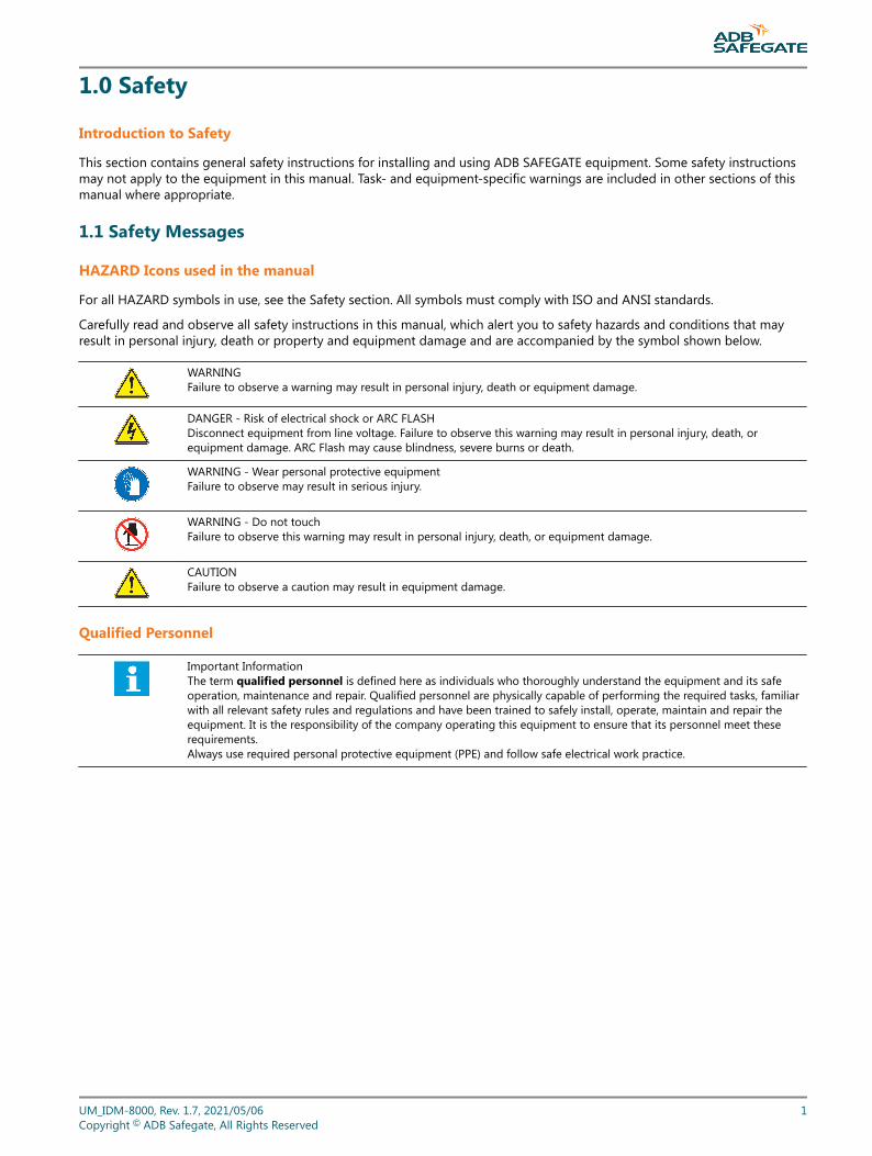
WARNINGFailure to observe a warning may result in personal injury, death or equipment damage.
DANGER - Risk of electrical shock or ARC FLASHDisconnect equipment from line voltage. Failure to observe this warning may result in personal injury, death, orequipment damage. ARC Flash may cause blindness, severe burns or death.
WARNING - Wear personal protective equipmentFailure to observe may result in serious injury.
WARNING - Do not touchFailure to observe this warning may result in personal injury, death, or equipment damage.
CAUTIONFailure to observe a caution may result in equipment damage.
Qualified Personnel
Important InformationThe term qualified personnel is defined here as individuals who thoroughly understand the equipment and its safeoperation, maintenance and repair. Qualified personnel are physically capable of performing the required tasks, familiarwith all relevant safety rules and regulations and have been trained to safely install, operate, maintain and repair theequipment. It is the responsibility of the company operating this equipment to ensure that its personnel meet theserequirements.Always use required personal protective equipment (PPE) and follow safe electrical work practice.
UM_IDM-8000, Rev. 1.7, 2021/05/06 1Copyright © ADB Safegate, All Rights Reserved
1.1.1 Introduction to Safety
CAUTIONUnsafe Equipment UseThis equipment may contain electrostatic devices, hazardous voltages and sharp edges on components
• Read installation instructions in their entirety before starting installation.• Become familiar with the general safety instructions in this section of the manual before installing,
operating, maintaining or repairing this equipment.• Read and carefully follow the instructions throughout this manual for performing specific tasks and
working with specific equipment.• Make this manual available to personnel installing, operating, maintaining or repairing this
equipment.• Follow all applicable safety procedures required by your company, industry standards and
government or other regulatory agencies.• Install all electrical connections to local code.• Use only electrical wire of sufficient gauge and insulation to handle the rated current demand. All
wiring must meet local codes.• Route electrical wiring along a protected path. Make sure they will not be damaged by moving
equipment.• Protect components from damage, wear, and harsh environment conditions.• Allow ample room for maintenance, panel accessibility, and cover removal.• Protect equipment with safety devices as specified by applicable safety regulations• If safety devices must be removed for installation, install them immediately after the work is
completed and check them for proper functioning prior to returning power to the circuit.
Failure to follow this instruction can result in serious injury or equipment damage
Additional Reference Materials
Important Information
• IEC - International Standards and Conformity Assessment for all electrical, electronic and related technologies.
• IEC 60364 - Electrical Installations in Buildings.
• FAA Advisory: AC 150/5340-26 (current edition), Maintenance of Airport Visual Aid Facilities.
• Maintenance personnel must refer to the maintenance procedure described in the ICAO Airport Services Manual,Part 9.
• ANSI/NFPA 79, Electrical Standards for Metalworking Machine Tools.
• National and local electrical codes and standards.
1.1.2 Intended Use
CAUTIONUse this equipment as intended by the manufacturerThis equipment is designed to perform a specific function, do not use this equipment for other purposes
• Using this equipment in ways other than described in this manual may result in personal injury, deathor property and equipment damage. Use this equipment only as described in this manual.
Failure to follow this instruction can result in serious injury or equipment damage
IDM 8000Safety
2Copyright © ADB Safegate, All Rights Reserved

1.1.3 Material Handling Precautions: Storage
CAUTIONImproper StorageStore this equipment properly
• If equipment is to be stored prior to installation, it must be protected from the weather and kept freeof condensation and dust.
Failure to follow this instruction can result in equipment damage
1.1.4 Material Handling: Heavy Equipment
DANGERUnstable loadUse caution when moving heavy equipment
• Use extreme care when moving heavy equipment.• Verify that the moving equipment is rated to handle the weight.• When removing equipment from a shipping pallet, carefully balance and secure it using a safety
strap.
Failure to follow this instruction can result in death, serious injury, or equipment damage
1.1.5 Operation Safety
CAUTIONImproper OperationDo Not Operate this equipment other than as specified by the manufacturer
• Only qualified personnel, physically capable of operating the equipment and with no impairments intheir judgment or reaction times, should operate this equipment.
• Read all system component manuals before operating this equipment. A thorough understanding ofsystem components and their operation will help you operate the system safely and efficiently.
• Before starting this equipment, check all safety interlocks, fire-detection systems, and protectivedevices such as panels and covers. Make sure all devices are fully functional. Do not operate thesystem if these devices are not working properly. Do not deactivate or bypass automatic safetyinterlocks or locked-out electrical disconnects or pneumatic valves.
• Protect equipment with safety devices as specified by applicable safety regulations.• If safety devices must be removed for installation, install them immediately after the work is
completed and check them for proper functioning.• Route electrical wiring along a protected path. Make sure they will not be damaged by moving
equipment.• Never operate equipment with a known malfunction.• Do not attempt to operate or service electrical equipment if standing water is present.• Use this equipment only in the environments for which it is rated. Do not operate this equipment in
humid, flammable, or explosive environments unless it has been rated for safe operation in theseenvironments.
• Never touch exposed electrical connections on equipment while the power is ON.
Failure to follow these instructions can result in equipment damage
UM_IDM-8000, Rev. 1.7, 2021/05/06 3Copyright © ADB Safegate, All Rights Reserved
1.1.6 Maintenance Safety
DANGERElectric Shock HazardThis equipment may contain electrostatic devices
• Do not operate a system that contains malfunctioning components. If a component malfunctions,turn the system OFF immediately.
• Disconnect and lock out electrical power.• Allow only qualified personnel to make repairs. Repair or replace the malfunctioning component
according to instructions provided in its manual.
Failure to follow these instructions can result in death or equipment damage
1.1.7 Material Handling Precautions, ESD
CAUTIONElectrostatic Sensitive DevicesThis equipment may contain electrostatic devices
• Protect from electrostatic discharge.• Electronic modules and components should be touched only when this is unavoidable e.g. soldering,
replacement.• Before touching any component of the cabinet you shall bring your body to the same potential as the
cabinet by touching a conductive earthed part of the cabinet.• Electronic modules or components must not be brought in contact with highly insulating materials
such as plastic sheets, synthetic fiber clothing. They must be laid down on conductive surfaces.• The tip of the soldering iron must be grounded.• Electronic modules and components must be stored and transported in conductive packing.
Failure to follow this instruction can result in equipment damage
IDM 8000Safety
4Copyright © ADB Safegate, All Rights Reserved
1.1.8 Arc Flash and Electric Shock Hazard
DANGERSeries Circuits have Hazardous VoltagesThis equipment produces high voltages to maintain the specified current - Do NOT Disconnect whileenergized.
• Allow only qualified personnel to perform maintenance, troubleshooting, and repair tasks.• Only persons who are properly trained and familiar with ADB SAFEGATE equipment are permitted to
service this equipment.• An open airfield current circuit is capable of generating >5000 Vac and may appear OFF to a meter.• Never unplug a device from a constant current circuit while it is operating; Arc flash may result.• Disconnect and lock out electrical power.• Always use safety devices when working on this equipment.• Follow the recommended maintenance procedures in the product manuals.• Do not service or adjust any equipment unless another person trained in first aid and CPR is present.• Connect all disconnected equipment ground cables and wires after servicing equipment. Ground all
conductive equipment.• Use only approved ADB SAFEGATE replacement parts. Using unapproved parts or making
unapproved modifications to equipment may void agency approvals and create safety hazards.• Check the interlock systems periodically to ensure their effectiveness.• Do not attempt to service electrical equipment if standing water is present. Use caution when
servicing electrical equipment in a high-humidity environment.• Use tools with insulated handles when working with airfield electrical equipment.
Failure to follow these instructions can result in death or equipment damage
UM_IDM-8000, Rev. 1.7, 2021/05/06 5Copyright © ADB Safegate, All Rights Reserved

IDM 8000Safety
6Copyright © ADB Safegate, All Rights Reserved
2.0 About this Manual
This document includes information with focus on safety, installation and maintenance procedures.
For more information, see www.adbsafegate.com.
NoteIt is very important to read this document before any work is started.
UM_IDM-8000, Rev. 1.7, 2021/05/06 7Copyright © ADB Safegate, All Rights Reserved

IDM 8000About this Manual
8Copyright © ADB Safegate, All Rights Reserved
3.0 Introduction
This manual includes installation, operation, maintenance and troubleshooting information for the IDM 8000 ConstantCurrent Regulator (CCR).
3.1 General
3.1.1 IDM 8000IDM 8000 is a microprocessor based CCR designed specifically for supplying airfield lighting serial circuits.
3.1.2 Airfield lighting serial circuit (AFL-circuit)Serial circuit is normally used at airports for power transmission from the CCR to rather remote located and power consuminglight fittings. Light fittings are connected via isolation transformers to a serial loop fed by the CCR. The output current of theCCR which defines the brilliancy of the light fittings is kept constant at each current step against supply, load andenvironmental changes. Current steps are provided in order to adjust the light output of the system to match with prevailingmeteorological conditions.
Power of the circuits normally varies up to 30kVa which means the max output current being always 6.6A that high outputvoltages must be used with larger CCRs. Normally all components (e.g. isolation transformers, connectors etc.) connected toseries circuits are designed for 5kV Rms – voltage.
In short the use of serial circuits and CCRs give the following benefits and disadvantages:
+ Provides equal brightness for all lamps due equal current in the serial loop.
+ Enables low cabling costs and transmission losses due rather low current level (6.6A).
- Because of high voltage used with larger CCRs extra precaution must be used when working with circuits. Regularmaintenance is also needed to maintain proper isolation levels.
3.1.3 Airfield lighting power circuit (AFL-circuit) design guidelines• Input power of the CCR is approx. 1.1 x rating of the CCR which should be considered when designing mains supply and
supply cable sizes for the CCR.
• Mains supply Rsce, min=175 for all CCR sizes (according to IEC 61000-3-4)
• Output primary cable losses are approx. 160W / km (6.6A / 6mm2 Cu).
• Output secondary cable losses can be significant and should be calculated according the lengths, diameters and materialsof the cables. Normally isolation transformer can tolerate up to 10% losses without reducing its output current.
• Isolation transformers efficiencies are normally 0.9 or better which should be taken in account together with the twoabove points when defining CCR rating for a circuit.
3.1.4 SpecificationsIDM 8000 is designed and manufactured in accordance with following specifications:
ICAO: Aerodrome design manual, Part 5
FAA: AC 150/5345-10E
CENELEC: Pr ENV 50231
IEC: 61822 Edition 1
IDM 8000 has also many unique new features not yet described in public specifications.
UM_IDM-8000, Rev. 1.7, 2021/05/06 9Copyright © ADB Safegate, All Rights Reserved
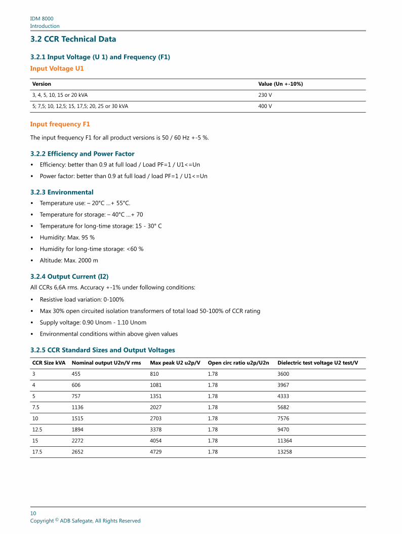
3.2 CCR Technical Data
3.2.1 Input Voltage (U 1) and Frequency (F1)
Input Voltage U1
Version Value (Un +-10%)
3, 4, 5, 10, 15 or 20 kVA 230 V
5; 7,5; 10, 12,5; 15, 17,5; 20, 25 or 30 kVA 400 V
Input frequency F1
The input frequency F1 for all product versions is 50 / 60 Hz +-5 %.
3.2.2 Efficiency and Power Factor• Efficiency: better than 0.9 at full load / Load PF=1 / U1<=Un
• Power factor: better than 0.9 at full load / load PF=1 / U1<=Un
3.2.3 Environmental• Temperature use: – 20°C …+ 55°C.
• Temperature for storage: – 40°C …+ 70
• Temperature for long-time storage: 15 - 30° C
• Humidity: Max. 95 %
• Humidity for long-time storage: <60 %
• Altitude: Max. 2000 m
3.2.4 Output Current (I2)All CCRs 6,6A rms. Accuracy +-1% under following conditions:
• Resistive load variation: 0-100%
• Max 30% open circuited isolation transformers of total load 50-100% of CCR rating
• Supply voltage: 0.90 Unom - 1.10 Unom
• Environmental conditions within above given values
3.2.5 CCR Standard Sizes and Output Voltages
CCR Size kVA Nominal output U2n/V rms Max peak U2 u2p/V Open circ ratio u2p/U2n Dielectric test voltage U2 test/V
3 455 810 1.78 3600
4 606 1081 1.78 3967
5 757 1351 1.78 4333
7.5 1136 2027 1.78 5682
10 1515 2703 1.78 7576
12.5 1894 3378 1.78 9470
15 2272 4054 1.78 11364
17.5 2652 4729 1.78 13258
IDM 8000Introduction
10Copyright © ADB Safegate, All Rights Reserved
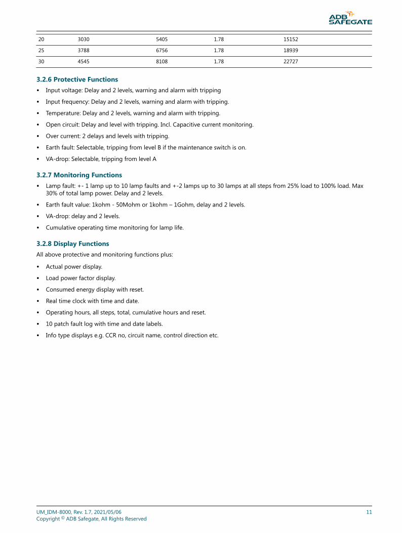
20 3030 5405 1.78 15152
25 3788 6756 1.78 18939
30 4545 8108 1.78 22727
3.2.6 Protective Functions• Input voltage: Delay and 2 levels, warning and alarm with tripping
• Input frequency: Delay and 2 levels, warning and alarm with tripping.
• Temperature: Delay and 2 levels, warning and alarm with tripping.
• Open circuit: Delay and level with tripping. Incl. Capacitive current monitoring.
• Over current: 2 delays and levels with tripping.
• Earth fault: Selectable, tripping from level B if the maintenance switch is on.
• VA-drop: Selectable, tripping from level A
3.2.7 Monitoring Functions• Lamp fault: +- 1 lamp up to 10 lamp faults and +-2 lamps up to 30 lamps at all steps from 25% load to 100% load. Max
30% of total lamp power. Delay and 2 levels.
• Earth fault value: 1kohm - 50Mohm or 1kohm – 1Gohm, delay and 2 levels.
• VA-drop: delay and 2 levels.
• Cumulative operating time monitoring for lamp life.
3.2.8 Display FunctionsAll above protective and monitoring functions plus:
• Actual power display.
• Load power factor display.
• Consumed energy display with reset.
• Real time clock with time and date.
• Operating hours, all steps, total, cumulative hours and reset.
• 10 patch fault log with time and date labels.
• Info type displays e.g. CCR no, circuit name, control direction etc.
UM_IDM-8000, Rev. 1.7, 2021/05/06 11Copyright © ADB Safegate, All Rights Reserved
3.2.9 Remote Control Interfaces• Parallel, selectable control voltage 24-60V DC, signal mode and coding.
• Serial, major field bus interface cards available. Duplicated, redundant interface possible.
3.3 CCR functional components
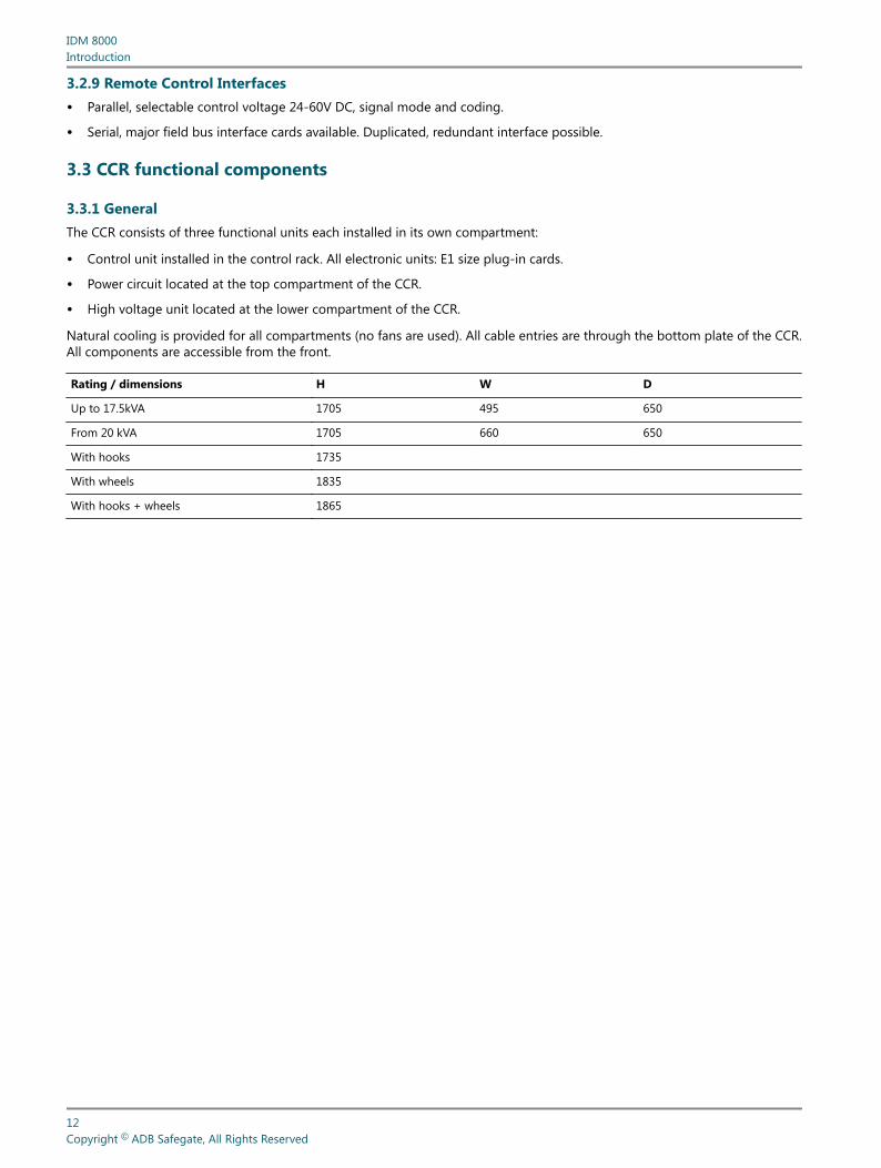
3.3.1 GeneralThe CCR consists of three functional units each installed in its own compartment:
• Control unit installed in the control rack. All electronic units: E1 size plug-in cards.
• Power circuit located at the top compartment of the CCR.
• High voltage unit located at the lower compartment of the CCR.
Natural cooling is provided for all compartments (no fans are used). All cable entries are through the bottom plate of the CCR.All components are accessible from the front.
Rating / dimensions H W D
Up to 17.5kVA 1705 495 650
From 20 kVA 1705 660 650
With hooks 1735
With wheels 1835
With hooks + wheels 1865
IDM 8000Introduction
12Copyright © ADB Safegate, All Rights Reserved
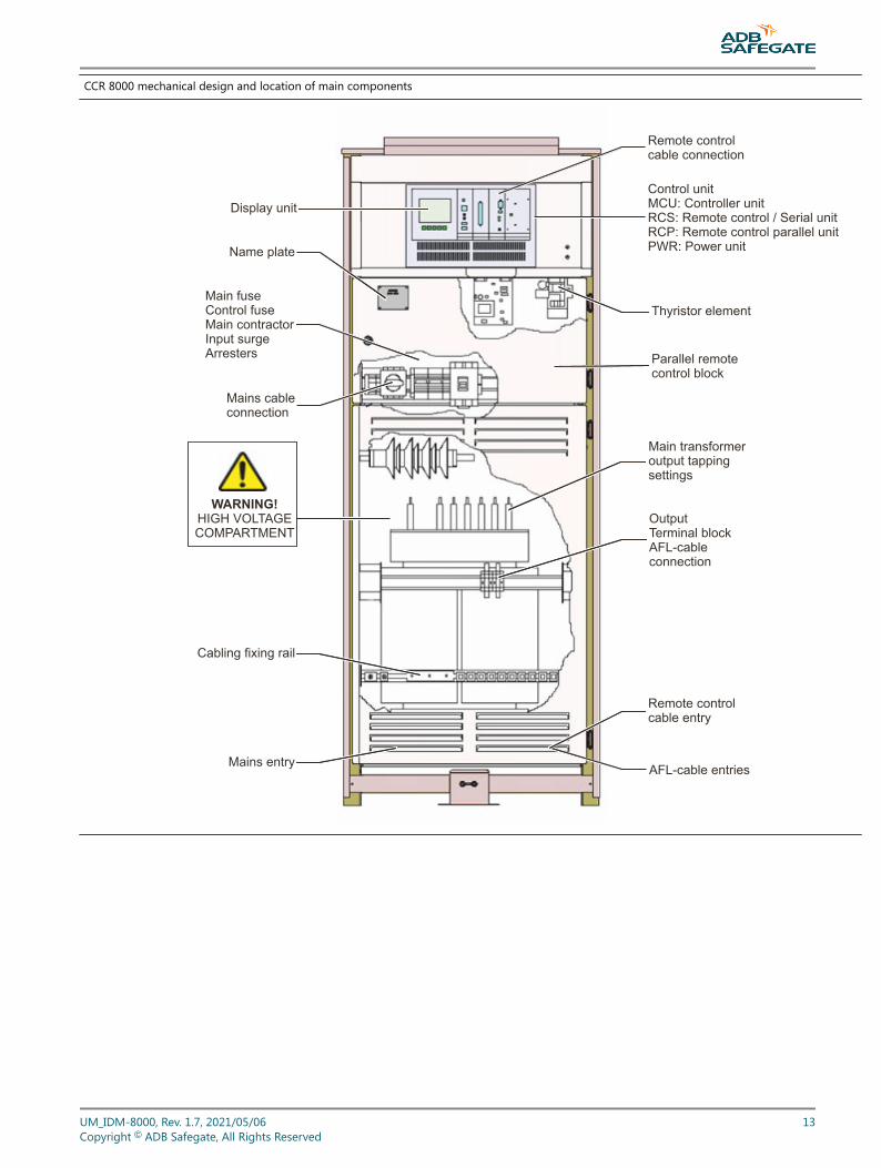
CCR 8000 mechanical design and location of main components
Display unit
Name plate
Main fuseControl fuseMain contractorInput surgeArresters
Mains cableconnection
Cabling fixing rail
Mains entry AFL-cable entries
Remote control cable entry
OutputTerminal blockAFL-cableconnection
Main transformeroutput tappingsettings
Parallel remote control block
Thyristor element
Control unitMCU: Controller unitRCS: Remote control / Serial unitRCP: Remote control parallel unitPWR: Power unit
Remote controlcable connection
WARNING!HIGH VOLTAGECOMPARTMENT
UM_IDM-8000, Rev. 1.7, 2021/05/06 13Copyright © ADB Safegate, All Rights Reserved
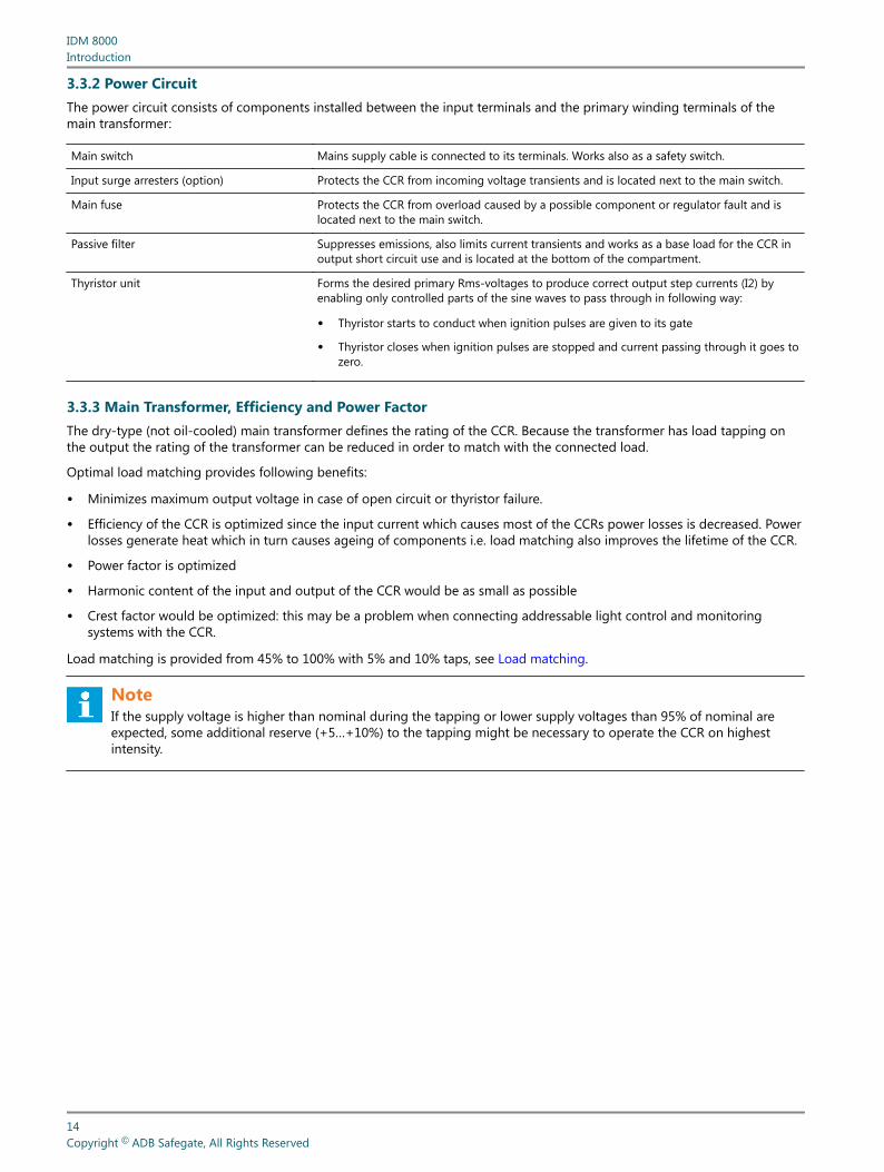
3.3.2 Power CircuitThe power circuit consists of components installed between the input terminals and the primary winding terminals of themain transformer:
Main switch Mains supply cable is connected to its terminals. Works also as a safety switch.
Input surge arresters (option) Protects the CCR from incoming voltage transients and is located next to the main switch.
Main fuse Protects the CCR from overload caused by a possible component or regulator fault and islocated next to the main switch.
Passive filter Suppresses emissions, also limits current transients and works as a base load for the CCR inoutput short circuit use and is located at the bottom of the compartment.
Thyristor unit Forms the desired primary Rms-voltages to produce correct output step currents (I2) byenabling only controlled parts of the sine waves to pass through in following way:
• Thyristor starts to conduct when ignition pulses are given to its gate
• Thyristor closes when ignition pulses are stopped and current passing through it goes tozero.
3.3.3 Main Transformer, Efficiency and Power FactorThe dry-type (not oil-cooled) main transformer defines the rating of the CCR. Because the transformer has load tapping onthe output the rating of the transformer can be reduced in order to match with the connected load.
Optimal load matching provides following benefits:
• Minimizes maximum output voltage in case of open circuit or thyristor failure.
• Efficiency of the CCR is optimized since the input current which causes most of the CCRs power losses is decreased. Powerlosses generate heat which in turn causes ageing of components i.e. load matching also improves the lifetime of the CCR.
• Power factor is optimized
• Harmonic content of the input and output of the CCR would be as small as possible
• Crest factor would be optimized: this may be a problem when connecting addressable light control and monitoringsystems with the CCR.
Load matching is provided from 45% to 100% with 5% and 10% taps, see Load matching.
NoteIf the supply voltage is higher than nominal during the tapping or lower supply voltages than 95% of nominal areexpected, some additional reserve (+5…+10%) to the tapping might be necessary to operate the CCR on highestintensity.
IDM 8000Introduction
14Copyright © ADB Safegate, All Rights Reserved
3.3.4 High Voltage CircuitThe high voltage circuit consists of components connected between the output terminals and main transformer secondarywinding terminals of the CCR and is assembled in a special high-voltage compartment. It consists of following components:
Output current measuring transformer Measures the output current I2 and provides feedback information to the regulator functionof the CCR. Secondary connected to control circuitry.
Output voltage measuring transformer Measures the output voltage U2 of the CCR and provides information to various monitoringfunctions. The output voltage is always scaled to 25V with every CCR size.
Surge arresters Protects the CCR from transients (e.g. lightning), coming from the AFL-circuit.
Earth fault module The earth fault module measures isolation resistance of the AFL-circuit. It is connected to thecircuit via high impedance / voltage resistor array and is completely isolated from the controlelectronics.With circuit selector function, earth fault is measured from all circuits simultaneously.
NoteDielectric strength of the earth fault module is 11 kV. Surge arresters connected tothe output of the CCR are recommended.
Direction changer orCircuit selector contactor block (optional)
The contactor block controls CCRs output circuits as follow:
• With circuit selector selecting is made in a way to cause minimum flicker of lights.Reduced switching current is used when switching off circuits in order to avoid regulatorovershoots.
• With direction changer changeover is made current less in order to provide maximumlifespan for the contacts and also to avoid transients in the output circuit.
NoteWith circuit selector all circuits are connected in series and short circuited. Circuitsare not disconnected from the high voltage output. Selection of any combination ofcircuits is made within the circuit selector by removing the shorts.The circuit selector dielectric strength is 11 000V according to FAA: AC 150/5345-5A.Surge arresters connected to the output of the CCR are recommended.
Output terminals Special output terminals are used to ease maintenance tasks:
• Terminal taps, standards for all CCRs.
• Series cut-out (SCO), option.
One pair of connectors is provided for each circuit of the CCR. Each pair is labeled with acapital and small character, e.g. A for output and a for return of the loop.For more information, see Appendix M – Output Terminals.
3.3.5 Control Unit
MCU control unit
The control unit is E1 size custom designed electronic card containing powerful 16-bit microprocessor with applicationprogram, and its peripheral circuits.
• Regulator function adjusts the thyristor control output according the RMS actual current value (I2) provided by the Rmscalculator (feedback) and set value defined by the user.
• Rms calculators define the actual output values by sampling the output waveforms and calculating effective (rms) valuesfrom the sample data.
The application program is stored on Flash-memory and can be therefore upgraded at site if desired. All set-parameters arestored in non-volatile EEPROM memory. Also, RAM memory is backed with battery for optimal performance in all operationalsituations.
UM_IDM-8000, Rev. 1.7, 2021/05/06 15Copyright © ADB Safegate, All Rights Reserved
Mother board
The mother board provides connections between the MCU and its peripherals like remote control unit, display unit andmeasuring channels. System hardware settings are made through dip-switch settings on motherboard. For more information,see Main Transformer, Efficiency and Power Factor.
Power unit
The plug-in E1 size power unit provides desired DC-voltages for the control electronics. Switch mode unit guarantees wideoperating voltage range and good efficiency.
3.3.6 Serial Control InterfaceSerial control interface is used with computer based control and monitoring systems using latest fieldbus technologies forCCR communication.
This interface is standard for all 8000 range CCRs and is designed under following criteria:
• To be compatible with most common fieldbus systems.
• Simple to interface: no data multiplexing, minimum “ripple” and round numbers (if possible no decimals) with data values.
• Possibility for redundant bus connection
The interface is realized with a credit card size communication card installed on E1 size plug in carrier card which again isinstalled in the RC-slot of the control rack. The fieldbus cable is connected directly to the connector on the communicationcard front plate.
General features
Each fieldbus interface (i.e. card) must have unique address on the bus.
• Fieldbuses using Daisy chain type of cabling (e.g. Profibus DP, cabling directly between CCRs) must be terminated at bothends of the physical cable link.
• Fieldbuses using Ethernet style cabling (e.g. Modbus TCP, separate cable for each CCR) do not need termination.
• Control and indication bit mode is continuous (i.e. static)
• Standard binary coding is used with control and indication step bits.
• With direction changer CCRs Lamp fault (LF) and power drop (VA) alarms and displays are for the current selecteddirection only. With circuit selector CCRs LF and VA alarms work only when all circuits are selected.
• The CCR monitors the fieldbus and in case the bus is not running it considers it to be offline (online when the bus is ok)and takes the failsafe setting until set to Off from the local control switch of the CCR or the bus returns to ok state.
• Heart beat-signal (Hb) confirms that real data connection exists with the host computer of the control systems and theCCR and is combined to online status monitoring of the CCR. (sometimes the fieldbus may be in ok state but has noconnection to its host computer)
• With redundant duplicated system the card in slot RM_1 (right side) is the primary interface and the card in RM_2 thesecondary interface. If the primary is online it controls the CCRs, if not the secondary controls and if both are offline thefailsafe setting is taken.
Related software settings
• CCR type: normal / direction changer / circuit selector. Control and indication bits are enabled according the CCR typeconfiguration.
• Failsafe setting defines how the CCR acts in case of bus failure.
• CCR size scales the size related measurement data ( U2, P2 ).
Redundant duplicated configuration is defined by dip-switches on the MB.
For more information, see Appendix C – Serial control interface signal list – Profibus DP or Appendix D – Serial controlinterface signal list – Modbus TCP.
IDM 8000Introduction
16Copyright © ADB Safegate, All Rights Reserved
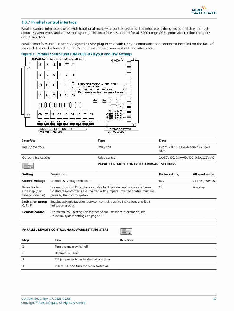
3.3.7 Parallel control interfaceParallel control interface is used with traditional multi-wire control systems. The interface is designed to match with mostcontrol system types and allows configuring. This interface is standard for all 8000 range CCRs (normal/direction changer/circuit selector).
Parallel interface unit is custom designed E1 size plug in card with D37 / F communication connector installed on the face ofthe card. The card is located in the RM-slot next to the power unit of the control rack.
Figure 1: Parallel control unit IDM 8000-03 layout and HW settings
Interface Type Data
Input / controls Relay coil Ucont = 0.8 – 1.6xUdcnom / R=3840ohm
Output / indications Relay contact 1A/30V DC, 0.3A/60V DC, 0.5A/125V AC
PARALLEL REMOTE CONTROL HARDWARE SETTINGS
Setting Description Factor setting Allowed range
Control voltage Control DC-voltage selection 60V 24 / 48 / 60V DC
Failsafe stepOne step (dec)Binary code(bin)
In case of control DC voltage or cable fault failsafe control status is taken.Control relays contacts are inverted with jumpers. Inverted control must begiven by the control system
Off Any step
Indication groupC, PI, FI
Enables galvanic isolation between control, positive indications and faultindication groups
Remote control Dip switch SW1 settings on mother board. For more information, seeHardware system settings on page 44.
PARALLEL REMOTE CONTROL HARDWARE SETTING STEPS
Step Task Remarks
1 Turn the main switch off
2 Remove RCP unit
3 Set jumper switches to desired positions
4 Insert RCP and turn the main switch on
UM_IDM-8000, Rev. 1.7, 2021/05/06 17Copyright © ADB Safegate, All Rights Reserved
RELATED SOFTWARE SETTINGS
Setting Menu Description
Dec/bin Remote control Coding of control signals (dec=1 signal/step,bin=standard bcd code)( 1=001; 2=010; 3=011; 4=100; 5=101; 6=110; 7=111 )
Cont/imp Remote control Control signals mode: Cont=continuous, imp=impulse,off sgn needed
Type System Control/indication signals purpose depends on theType selection.See HW-settings and parallel connection signal list.
ComF-m Remote control Defines if all fault signals are summed to Com-faultindication (SumF) or it contains only U1, f1 and Talarms (SysF).
Parallel control interface and indication signals: Appendix E – Parallel control interface signal list. Example connection in Appendix F – Parallel remote control example.
IDM 8000Introduction
18Copyright © ADB Safegate, All Rights Reserved
4.0 User Interface
4.1 Control functions
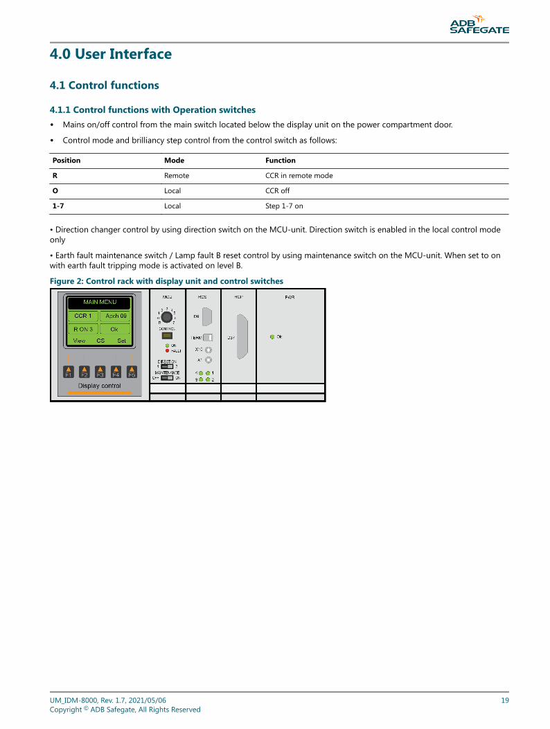
4.1.1 Control functions with Operation switches• Mains on/off control from the main switch located below the display unit on the power compartment door.
• Control mode and brilliancy step control from the control switch as follows:
Position Mode Function
R Remote CCR in remote mode
O Local CCR off
1-7 Local Step 1-7 on
• Direction changer control by using direction switch on the MCU-unit. Direction switch is enabled in the local control modeonly
• Earth fault maintenance switch / Lamp fault B reset control by using maintenance switch on the MCU-unit. When set to onwith earth fault tripping mode is activated on level B.
Figure 2: Control rack with display unit and control switches
UM_IDM-8000, Rev. 1.7, 2021/05/06 19Copyright © ADB Safegate, All Rights Reserved
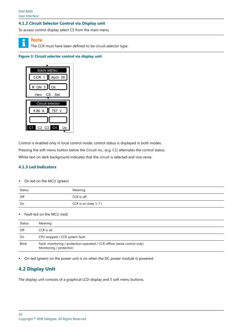
4.1.2 Circuit Selector Control via Display unitTo access control display select CS from the main menu.
NoteThe CCR must have been defined to be circuit selector type.
Figure 3: Circuit selector control via display unit
Control is enabled only in local control mode; control status is displayed in both modes.
Pressing the soft menu button below the Circuit no., (e.g. C1) alternates the control status.
White text on dark background indicates that the circuit is selected and vice verse.
4.1.3 Led Indicators
• On led on the MCU (green)
Status Meaning
Off CCR is off
On CCR is on (step 1-7 )
• Fault-led on the MCU (red)
Status Meaning
Off CCR is ok
On CPU stopped / CCR system fault
Blink Fault: monitoring / protection operated / CCR offline (serial control only)Monitoring / protection
• On-led (green) on the power unit is on when the DC power module is powered.
4.2 Display Unit
The display unit consists of a graphical LCD-display and 5 soft menu buttons.
IDM 8000User Interface
20Copyright © ADB Safegate, All Rights Reserved

Each display window consists of header, 2 function dependent data fields, 2 permanent status fields and 5 functiondependent soft menu texts.
UM_IDM-8000, Rev. 1.7, 2021/05/06 21Copyright © ADB Safegate, All Rights Reserved
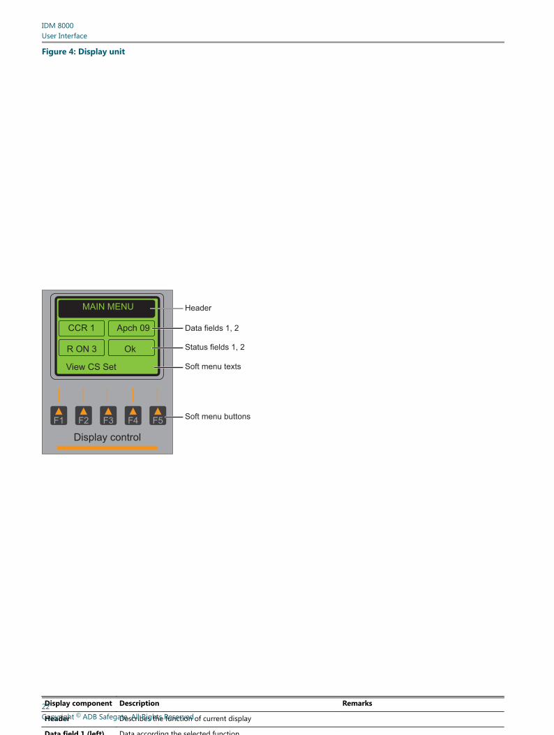
Figure 4: Display unit
MAIN MENU
CCR 1 Apch 09
R ON 3 Ok
View CS Set
Display control
F1 F2 F3 F4 F5
Header
Data fields 1, 2
Status fields 1, 2
Soft menu texts
Soft menu buttons
Display component Description Remarks
Header Describes the function of current display
Data field 1 (left) Data according the selected function
IDM 8000User Interface
22Copyright © ADB Safegate, All Rights Reserved
Data field 2 (right) Data according the selected function
Status field 1 (left) CCR control status Permanent, not function dependent
1. Control mode status R = remote, B = profibus connection fault, r =remote control offline, N = remote/no carddetected, L = local
2. Control direction 1, 2 Only with direction changer
3. Control step status CCR. Off, On 1-7
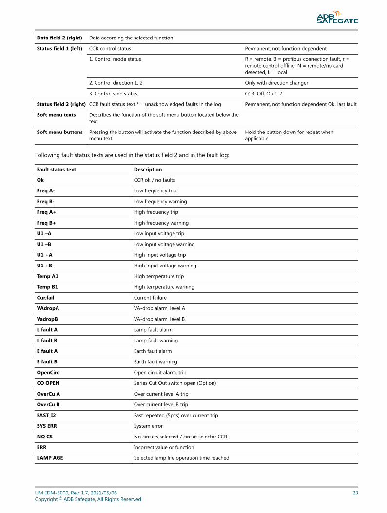
Status field 2 (right) CCR fault status text * = unacknowledged faults in the log Permanent, not function dependent Ok, last fault
Soft menu texts Describes the function of the soft menu button located below thetext
Soft menu buttons Pressing the button will activate the function described by abovemenu text
Hold the button down for repeat whenapplicable
Following fault status texts are used in the status field 2 and in the fault log:
Fault status text Description
Ok CCR ok / no faults
Freq A- Low frequency trip
Freq B- Low frequency warning
Freq A+ High frequency trip
Freq B+ High frequency warning
U1 –A Low input voltage trip
U1 –B Low input voltage warning
U1 +A High input voltage trip
U1 +B High input voltage warning
Temp A1 High temperature trip
Temp B1 High temperature warning
Cur.fail Current failure
VAdropA VA-drop alarm, level A
VadropB VA-drop alarm, level B
L fault A Lamp fault alarm
L fault B Lamp fault warning
E fault A Earth fault alarm
E fault B Earth fault warning
OpenCirc Open circuit alarm, trip
CO OPEN Series Cut Out switch open (Option)
OverCu A Over current level A trip
OverCu B Over current level B trip
FAST_I2 Fast repeated (5pcs) over current trip
SYS ERR System error
NO CS No circuits selected / circuit selector CCR
ERR Incorrect value or function
LAMP AGE Selected lamp life operation time reached
UM_IDM-8000, Rev. 1.7, 2021/05/06 23Copyright © ADB Safegate, All Rights Reserved
4.2.1 Display Interface Main Menu Structure
The main menu has three selections:
• View Viewing the values without affecting any set values.
• Cs Circuit selector control (only if the CCR is defined as a circuit selector CCR).
• Set CCR calibration and setting functions. Password protection of settings menu is selectable from the Sys settings.Factory setting for password protection is not in use (Off).
4.2.2 The set menu is divided into 3 sub menus:
• Cal Calibrating functions
• Prot Protective functions; monitoring functions which are able to trip the CCR
• Set Setting functions; other monitoring and system configuration functions
4.2.3 Commonly used symbols in all display menus:
• More Brings more equal level displays
• Up Brings you back to upper level display
4.3 View functions
IDM 8000User Interface
24Copyright © ADB Safegate, All Rights Reserved
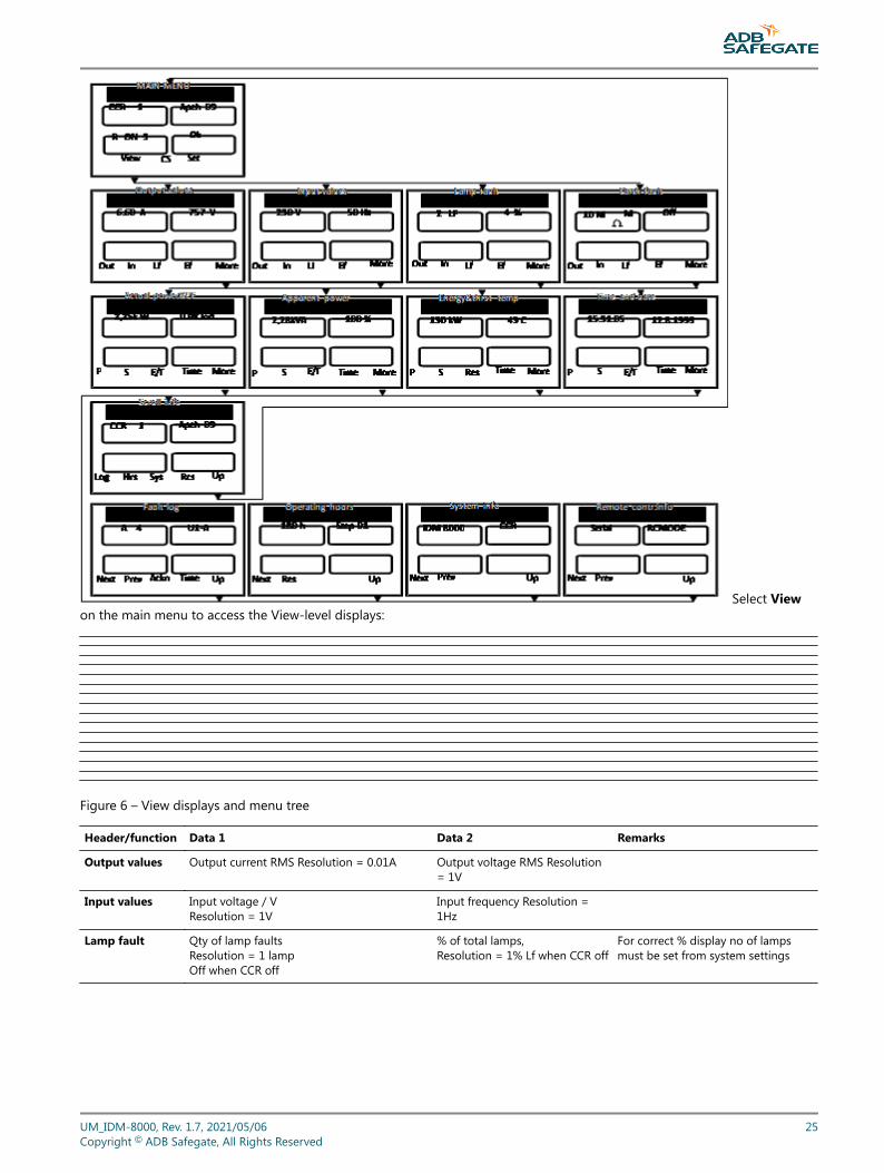
Select Viewon the main menu to access the View-level displays:
Figure 6 – View displays and menu tree
Header/function Data 1 Data 2 Remarks
Output values Output current RMS Resolution = 0.01A Output voltage RMS Resolution= 1V
Input values Input voltage / VResolution = 1V
Input frequency Resolution =1Hz
Lamp fault Qty of lamp faultsResolution = 1 lampOff when CCR off
% of total lamps,Resolution = 1% Lf when CCR off
For correct % display no of lampsmust be set from system settings
UM_IDM-8000, Rev. 1.7, 2021/05/06 25Copyright © ADB Safegate, All Rights Reserved
Earth fault Isolation resistanceVariable resolution *Off when CCR local/off M=maintenanceswitch on and M-switch selected
Reserved * Resolution50M ohm range:1k: 0k-999k,0.01M: 1.00M-9.99M,0.1M: 10.0M-50.0M.1G ohm range:1k: 0k-99k,0.01M: 0.10M-99.99M0.01G: 0.10G-1.00G
Actual power&PF Load actual power Resolution = 0,01/0,1kW Load power factor Resolution =0.01
Apparent power Load apparent power Resolution =0,01/0,1kVA“-“ When CCR off
% of recorded full load value“---“ If not calibrated
Full load values recorded during lampfault calibration.
Energy&thrst Temp
Energy spent since last reset. Res to resetResolution = 1kWh/1MWh
Thyristor element temperatureResolution = 1C
Max display 999 MWh
Time and date Time hh.mm.ss Date dd.mm.yyyy
Scroll info CCR no Circuit, direction Access to scroll info displays. Up togo back to main menu
View scroll info displays:
Header/function Data 1 Data 2 Remarks
Fault log A = acknowledged Fault number1-101 = oldest fault
Fault text. Next = Next faultPrev = Previous faultAckn = AcknowledgeTime = Fault occurrence time and date
Operating hours Elapsed hours Step no 01-07 – TotalCstep 01-07 – Ctotal(C = Cumulative)
Next = next hoursRes = reset hoursCumulative hours, will not reset
System info System data Datatype For more information, see 2.6.8 System settings.
Run 7 / xx %. Tap % Max step, Load % of main trafo capacity
xx,xx V. DC +5V, +-12V Internal DC voltages
XXXX DIP POS 2.6.7 Hardware System settings (2.6.7)
LEDS TEST Led test function for MCU LEDs
Remote control info Data Datatype For more information, see 2.6.9 Remote control settings.
IDM 8000User Interface
26Copyright © ADB Safegate, All Rights Reserved
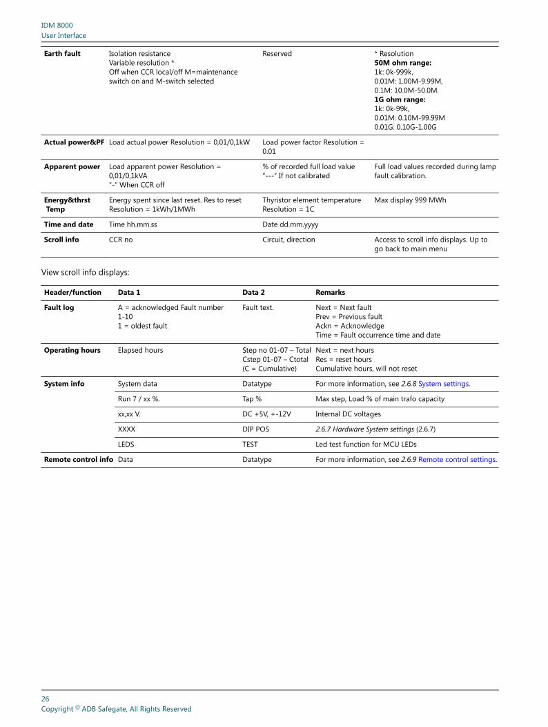
4.4 Calibration functions
Select Set /Cal to access the calibration level displays:
Figure 7 – Calibration displays and menu tree
If password protection is selected from system settings, you are asked for a password before entering the SETTINGS display.For more information, see selecting password protection in the section 2.6.8 System settings.
4.4.1 Output Current I2 and Voltage U2 Calibration
Header/function Data 1 Data 2 Remarks
I2/U2 calibration I2 / AU2 / V
I2 CalU2 Cal
Next = U2 calNext = I2 cal+ - adjust
UM_IDM-8000, Rev. 1.7, 2021/05/06 27Copyright © ADB Safegate, All Rights Reserved
I2 calibration
1. Connect external calibrated RMS A-meter (10A, accuracy better than 1%) in series with the load circuit. Use at least 10% load of the CCRcapacity.
Warning!High voltage circuit – De-energize CCR before connecting!
Note : For more information on easy meter connection, see Series Cut Out (SCO) option in Appendix M – Ouput Terminals. Clamp meteraccuracy is normally not adequate for 1% accuracy. For periodic maintenance checks, clamp type meter is still recommended for safety reasons.
1. Select the second highest current step (approx. 5A).
1. Go to I2/U2 calibration: select Set/Cal/Out.
1. Adjust the I2 reading on datafield 1 to equal with the external meter reading.
1. Make sure that the readings are equal then select Set.
Warning!Make sure that there is max 10% deviation between the two readings. Selecting setwith bigger difference between the readings may result to over current on the outputcircuit!
1. Check that both readings are equal, if necessary repeat steps 4-6.
Note : I2 calibration affects also to VA-drop function.Calibration with short circuit load (U2 = 0) is not allowed.Calibration of more than ±10% from factory defaults is not allowed -> ERR indication in display.
U2 calibration
1. Connect external calibrated RMS V-meter (Min 30V, accuracy better than 1%) to the voltage transformer testoutputs located on the right side of the power unit of the control rack.
1. Select the maximum current step (6.6A).
1. Go to I2/U2 calibration: select Set/Cal/Out and then Next.
1. Check the external meter reading and adjust the U2 reading on data 1 to be equal with the external meter reading and then select Set .
Note : Round up to next bigger value e.g. 20.12->20.2.
1. Make sure that the both readings are equal and if necessary repeat step 4.
Note : U2 calibration affects also to VA-drop functionCalibration of more than ±10% from factory defaults is not allowed -> ERR indication in display.
4.4.2 Input Voltage U1 Calibration
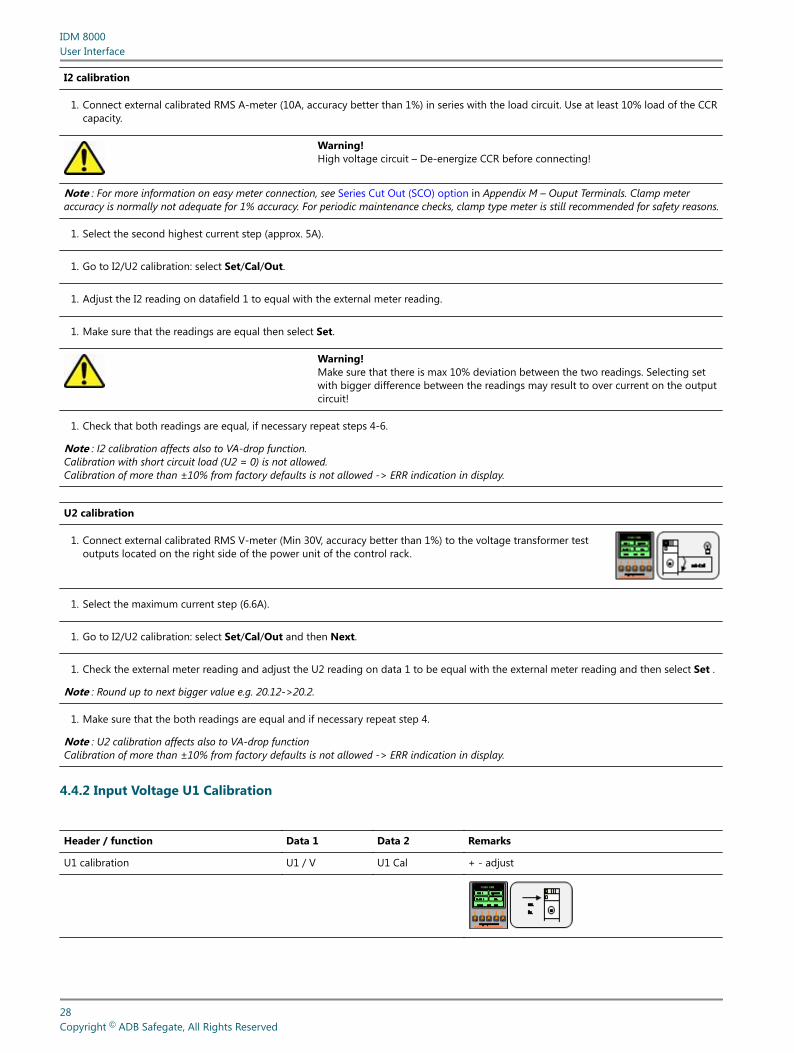
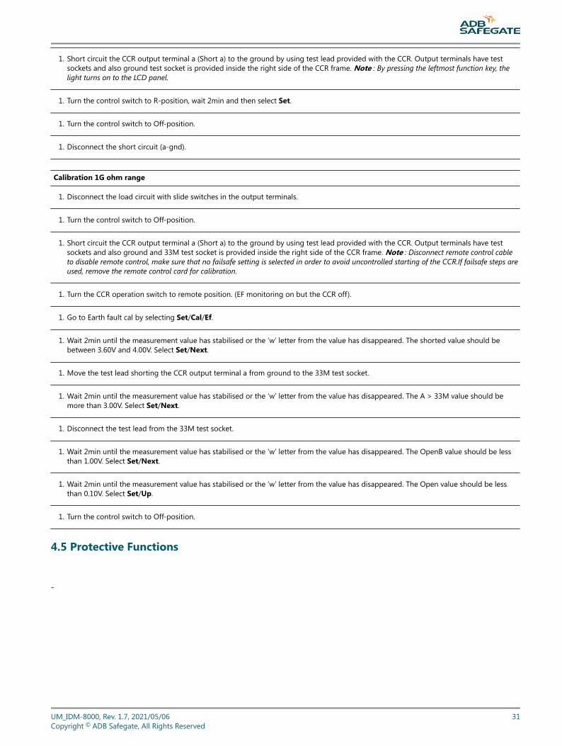
Header / function Data 1 Data 2 Remarks
U1 calibration U1 / V U1 Cal + - adjust
IDM 8000User Interface
28Copyright © ADB Safegate, All Rights Reserved
U1 calibration
1. Connect external calibrated V-meter (appropriate scale, accuracy better than 1%) to the CCR mains input terminals (main switch).
Warning!Line voltage circuit – use appropriate test probes!
1. Go to /U1 calibration: select Set/Cal/ In.
1. Adjust the U1 reading on data 1 to equal with the external meter reading.
1. Make sure that the readings are equal then select Set.
1. Check View/In that both readings are equal, if necessary repeat steps 3-5.
Note : Calibration for DC1 (+5V), DC2 (+12V) and DC3 (-12V) system voltages also provided in this display. Factory settings: not necessary tocalibrate during commissioning.
4.4.3 Lamp Fault and VA-Drop Calibration
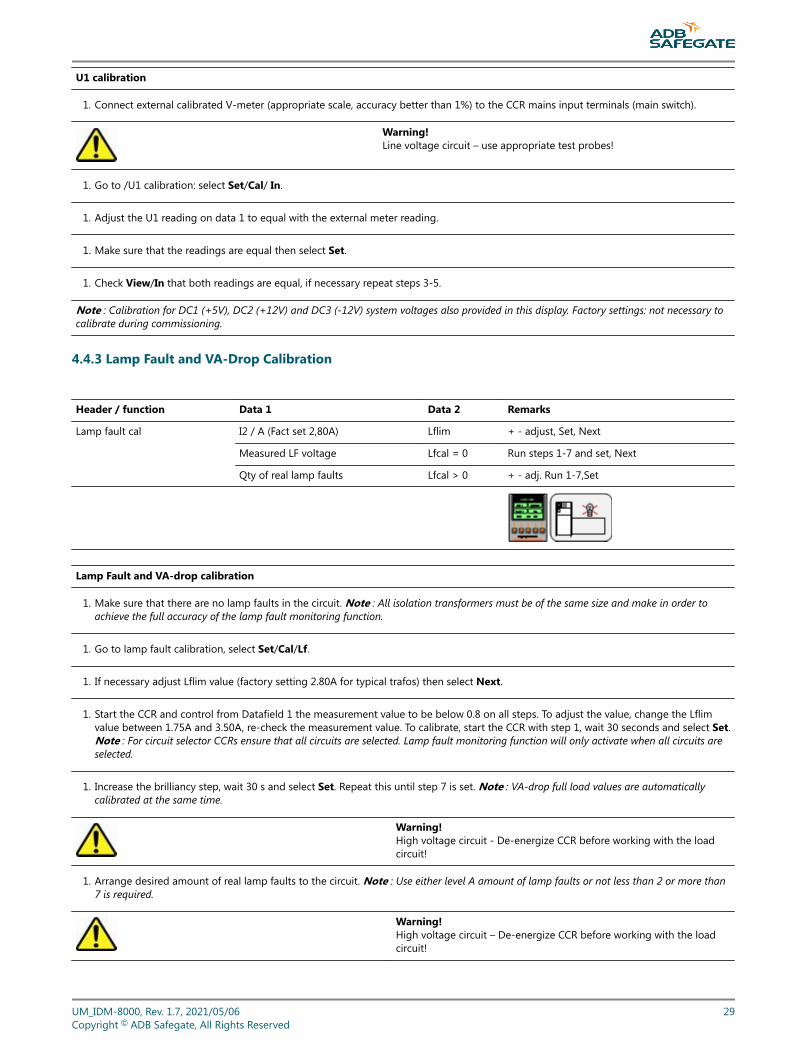
Header / function Data 1 Data 2 Remarks
Lamp fault cal I2 / A (Fact set 2,80A) Lflim + - adjust, Set, Next
Measured LF voltage Lfcal = 0 Run steps 1-7 and set, Next
Qty of real lamp faults Lfcal > 0 + - adj. Run 1-7,Set
Lamp Fault and VA-drop calibration
1. Make sure that there are no lamp faults in the circuit. Note : All isolation transformers must be of the same size and make in order toachieve the full accuracy of the lamp fault monitoring function.
1. Go to lamp fault calibration, select Set/Cal/Lf.
1. If necessary adjust Lflim value (factory setting 2.80A for typical trafos) then select Next.
1. Start the CCR and control from Datafield 1 the measurement value to be below 0.8 on all steps. To adjust the value, change the Lflimvalue between 1.75A and 3.50A, re-check the measurement value. To calibrate, start the CCR with step 1, wait 30 seconds and select Set.Note : For circuit selector CCRs ensure that all circuits are selected. Lamp fault monitoring function will only activate when all circuits areselected.
1. Increase the brilliancy step, wait 30 s and select Set. Repeat this until step 7 is set. Note : VA-drop full load values are automaticallycalibrated at the same time.
Warning!High voltage circuit - De-energize CCR before working with the loadcircuit!
1. Arrange desired amount of real lamp faults to the circuit. Note : Use either level A amount of lamp faults or not less than 2 or more than7 is required.
Warning!High voltage circuit – De-energize CCR before working with the loadcircuit!
UM_IDM-8000, Rev. 1.7, 2021/05/06 29Copyright © ADB Safegate, All Rights Reserved
1. Return to lamp fault cal. Use Next to go to Lfcal>0.
1. Adjust selected number of real lamp faults into the datafield 1 with +/- buttons.
1. Repeat steps 5 and 6.
1. Check from the View/Lamp fault display that correct number of lamp faults is displayed. If level A lamp faults was selected, check thatalarm is given in local display.
1. Correct lamp faults to level B and run CCR to check that level B alarm is given.
1. Correct the lamp faults in the circuit and check that the lamp fault display is 0
1. If the CCR is with direction changer repeat steps 1-13 for the 2nd direction.
4.4.4 Earth Fault Calibration
Warning!Extra precaution must be used when working with high-voltage circuits! Always de-energize the CCR before making connections.
50M ohm range
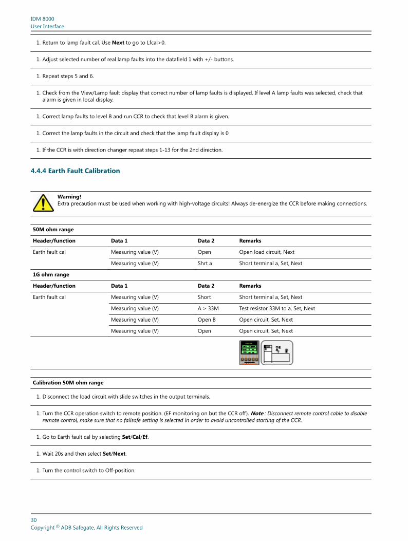
Header/function Data 1 Data 2 Remarks
Earth fault cal Measuring value (V) Open Open load circuit, Next
Measuring value (V) Shrt a Short terminal a, Set, Next
1G ohm range
Header/function Data 1 Data 2 Remarks
Earth fault cal Measuring value (V) Short Short terminal a, Set, Next
Measuring value (V) A > 33M Test resistor 33M to a, Set, Next
Measuring value (V) Open B Open circuit, Set, Next
Measuring value (V) Open Open circuit, Set, Next
Calibration 50M ohm range
1. Disconnect the load circuit with slide switches in the output terminals.
1. Turn the CCR operation switch to remote position. (EF monitoring on but the CCR off). Note : Disconnect remote control cable to disableremote control, make sure that no failsafe setting is selected in order to avoid uncontrolled starting of the CCR.
1. Go to Earth fault cal by selecting Set/Cal/Ef.
1. Wait 20s and then select Set/Next.
1. Turn the control switch to Off-position.
IDM 8000User Interface
30Copyright © ADB Safegate, All Rights Reserved
1. Short circuit the CCR output terminal a (Short a) to the ground by using test lead provided with the CCR. Output terminals have testsockets and also ground test socket is provided inside the right side of the CCR frame. Note : By pressing the leftmost function key, thelight turns on to the LCD panel.
1. Turn the control switch to R-position, wait 2min and then select Set.
1. Turn the control switch to Off-position.
1. Disconnect the short circuit (a-gnd).
Calibration 1G ohm range
1. Disconnect the load circuit with slide switches in the output terminals.
1. Turn the control switch to Off-position.
1. Short circuit the CCR output terminal a (Short a) to the ground by using test lead provided with the CCR. Output terminals have testsockets and also ground and 33M test socket is provided inside the right side of the CCR frame. Note : Disconnect remote control cableto disable remote control, make sure that no failsafe setting is selected in order to avoid uncontrolled starting of the CCR.If failsafe steps areused, remove the remote control card for calibration.
1. Turn the CCR operation switch to remote position. (EF monitoring on but the CCR off).
1. Go to Earth fault cal by selecting Set/Cal/Ef.
1. Wait 2min until the measurement value has stabilised or the ‘w’ letter from the value has disappeared. The shorted value should bebetween 3.60V and 4.00V. Select Set/Next.
1. Move the test lead shorting the CCR output terminal a from ground to the 33M test socket.
1. Wait 2min until the measurement value has stabilised or the ‘w’ letter from the value has disappeared. The A > 33M value should bemore than 3.00V. Select Set/Next.
1. Disconnect the test lead from the 33M test socket.
1. Wait 2min until the measurement value has stabilised or the ‘w’ letter from the value has disappeared. The OpenB value should be lessthan 1.00V. Select Set/Next.
1. Wait 2min until the measurement value has stabilised or the ‘w’ letter from the value has disappeared. The Open value should be lessthan 0.10V. Select Set/Up.
1. Turn the control switch to Off-position.
4.5 Protective Functions
-
UM_IDM-8000, Rev. 1.7, 2021/05/06 31Copyright © ADB Safegate, All Rights Reserved
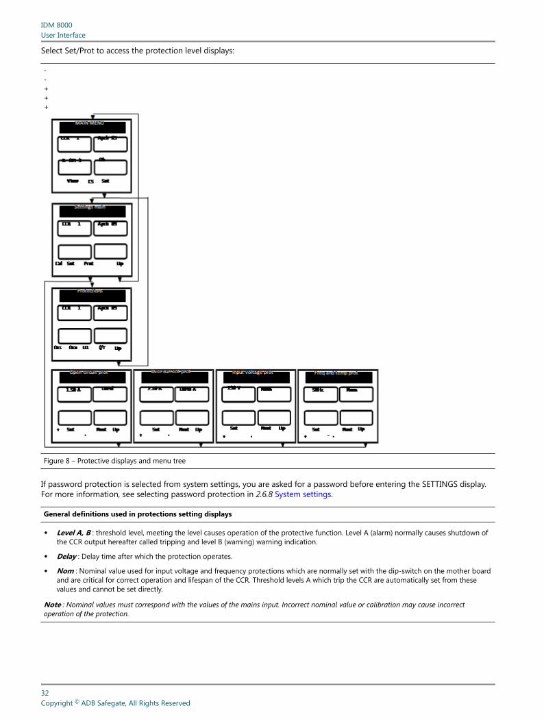
Select Set/Prot to access the protection level displays:
- - + + +
Figure 8 – Protective displays and menu tree
If password protection is selected from system settings, you are asked for a password before entering the SETTINGS display.For more information, see selecting password protection in 2.6.8 System settings.
General definitions used in protections setting displays
• Level A, B : threshold level, meeting the level causes operation of the protective function. Level A (alarm) normally causes shutdown ofthe CCR output hereafter called tripping and level B (warning) warning indication.
• Delay : Delay time after which the protection operates.
• Nom : Nominal value used for input voltage and frequency protections which are normally set with the dip-switch on the mother boardand are critical for correct operation and lifespan of the CCR. Threshold levels A which trip the CCR are automatically set from thesevalues and cannot be set directly.
Note : Nominal values must correspond with the values of the mains input. Incorrect nominal value or calibration may cause incorrectoperation of the protection.
IDM 8000User Interface
32Copyright © ADB Safegate, All Rights Reserved
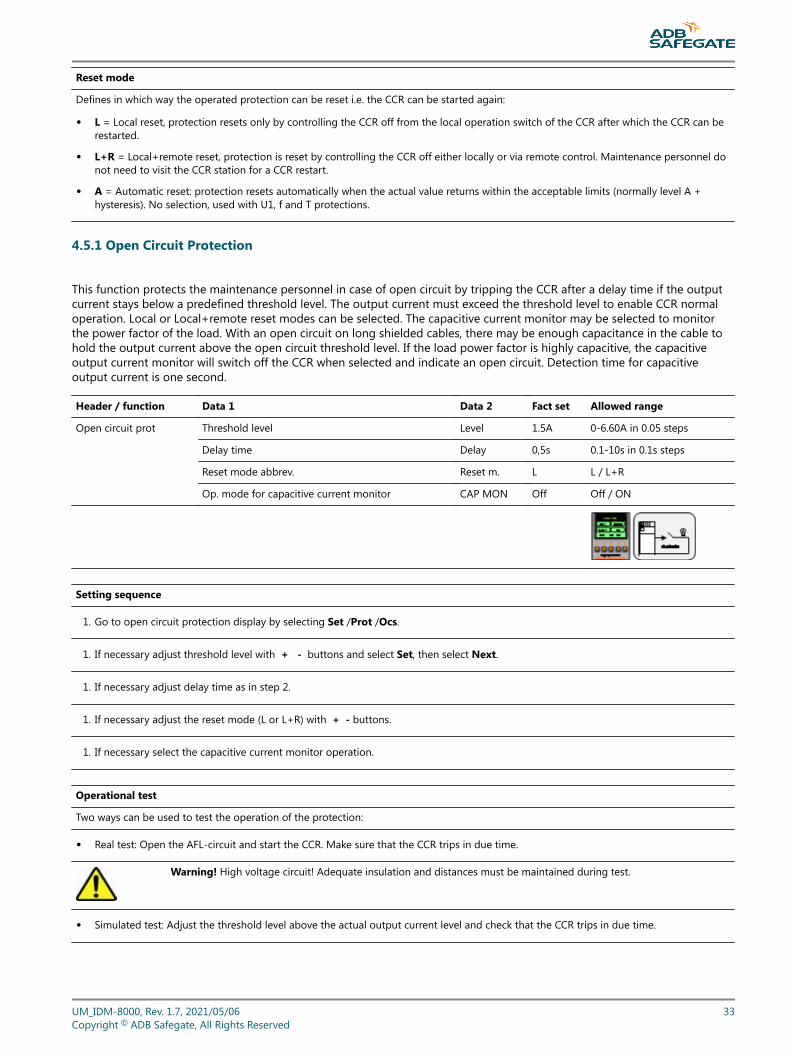
Reset mode
Defines in which way the operated protection can be reset i.e. the CCR can be started again:
• L = Local reset, protection resets only by controlling the CCR off from the local operation switch of the CCR after which the CCR can berestarted.
• L+R = Local+remote reset, protection is reset by controlling the CCR off either locally or via remote control. Maintenance personnel donot need to visit the CCR station for a CCR restart.
• A = Automatic reset: protection resets automatically when the actual value returns within the acceptable limits (normally level A +hysteresis). No selection, used with U1, f and T protections.
4.5.1 Open Circuit Protection
This function protects the maintenance personnel in case of open circuit by tripping the CCR after a delay time if the outputcurrent stays below a predefined threshold level. The output current must exceed the threshold level to enable CCR normaloperation. Local or Local+remote reset modes can be selected. The capacitive current monitor may be selected to monitorthe power factor of the load. With an open circuit on long shielded cables, there may be enough capacitance in the cable tohold the output current above the open circuit threshold level. If the load power factor is highly capacitive, the capacitiveoutput current monitor will switch off the CCR when selected and indicate an open circuit. Detection time for capacitiveoutput current is one second.
Header / function Data 1 Data 2 Fact set Allowed range
Open circuit prot Threshold level Level 1.5A 0-6.60A in 0.05 steps
Delay time Delay 0,5s 0.1-10s in 0.1s steps
Reset mode abbrev. Reset m. L L / L+R
Op. mode for capacitive current monitor CAP MON Off Off / ON
Setting sequence
1. Go to open circuit protection display by selecting Set /Prot /Ocs.
1. If necessary adjust threshold level with + - buttons and select Set, then select Next.
1. If necessary adjust delay time as in step 2.
1. If necessary adjust the reset mode (L or L+R) with + - buttons.
1. If necessary select the capacitive current monitor operation.
Operational test
Two ways can be used to test the operation of the protection:
• Real test: Open the AFL-circuit and start the CCR. Make sure that the CCR trips in due time.
Warning! High voltage circuit! Adequate insulation and distances must be maintained during test.
• Simulated test: Adjust the threshold level above the actual output current level and check that the CCR trips in due time.
UM_IDM-8000, Rev. 1.7, 2021/05/06 33Copyright © ADB Safegate, All Rights Reserved
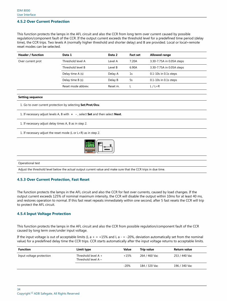
4.5.2 Over Current Protection
This function protects the lamps in the AFL circuit and also the CCR from long term over current caused by possibleregulation/component fault of the CCR. If the output current exceeds the threshold level for a predefined time period (delaytime), the CCR trips. Two levels A (normally higher threshold and shorter delay) and B are provided. Local or local+remotereset modes can be selected.
Header / function Data 1 Data 2 Fact set Allowed range
Over current prot Threshold level A Level A 7.20A 3.30-7.75A in 0.05A steps
Threshold level B Level B 6.90A 3.30-7.75A in 0.05A steps
Delay time A (s) Delay A 1s 0.1-10s in 0.1s steps
Delay time B (s) Delay B 5s 0.1-10s in 0.1s steps
Reset mode abbrev. Reset m. L L / L+R
Setting sequence
1. Go to over current protection by selecting Set/Prot/Ocu.
1. If necessary adjust levels A, B with + - , select Set and then select Next.
1. If necessary adjust delay times A, B as in step 2.
1. If necessary adjust the reset mode (L or L+R) as in step 2.
Operational test
Adjust the threshold level below the actual output current value and make sure that the CCR trips in due time.
4.5.3 Over Current Protection, Fast Reset
The function protects the lamps in the AFL circuit and also the CCR for fast over currents, caused by load changes. If theoutput current exceeds 125% of nominal maximum intensity, the CCR will disable the output within 10ms for at least 40 ms,and restores operation to normal. If this fast reset repeats immediately within one second, after 5 fast resets the CCR will tripto protect the AFL circuit.
4.5.4 Input Voltage Protection
This function protects the lamps in the AFL circuit and also the CCR from possible regulation/component fault of the CCRcaused by long term over/under input voltage.
If the input voltage is out of acceptable limits (L a + = +15% and L a - = -20%, deviation automatically set from the nominalvalue) for a predefined delay time the CCR trips. CCR starts automatically after the input voltage returns to acceptable limits.
Function Limit type Value Trip value Return value
Input voltage protection Threshold level A +Threshold level A –
+15% 264 / 460 Vac 253 / 440 Vac
-20% 184 / 320 Vac 196 / 340 Vac
IDM 8000User Interface
34Copyright © ADB Safegate, All Rights Reserved
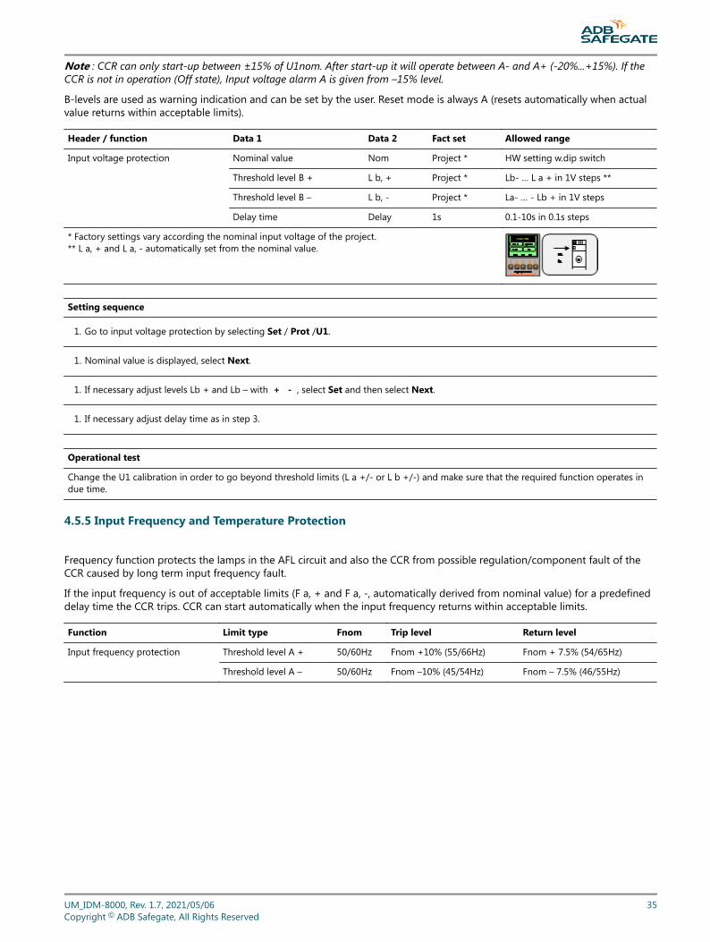
Note : CCR can only start-up between ±15% of U1nom. After start-up it will operate between A- and A+ (-20%...+15%). If theCCR is not in operation (Off state), Input voltage alarm A is given from –15% level.
B-levels are used as warning indication and can be set by the user. Reset mode is always A (resets automatically when actualvalue returns within acceptable limits).
Header / function Data 1 Data 2 Fact set Allowed range
Input voltage protection Nominal value Nom Project * HW setting w.dip switch
Threshold level B + L b, + Project * Lb- … L a + in 1V steps **
Threshold level B – L b, - Project * La- … - Lb + in 1V steps
Delay time Delay 1s 0.1-10s in 0.1s steps
* Factory settings vary according the nominal input voltage of the project.** L a, + and L a, - automatically set from the nominal value.
Setting sequence
1. Go to input voltage protection by selecting Set / Prot /U1.
1. Nominal value is displayed, select Next.
1. If necessary adjust levels Lb + and Lb – with + - , select Set and then select Next.
1. If necessary adjust delay time as in step 3.
Operational test
Change the U1 calibration in order to go beyond threshold limits (L a +/- or L b +/-) and make sure that the required function operates indue time.
4.5.5 Input Frequency and Temperature Protection
Frequency function protects the lamps in the AFL circuit and also the CCR from possible regulation/component fault of theCCR caused by long term input frequency fault.
If the input frequency is out of acceptable limits (F a, + and F a, -, automatically derived from nominal value) for a predefineddelay time the CCR trips. CCR can start automatically when the input frequency returns within acceptable limits.
Function Limit type Fnom Trip level Return level
Input frequency protection Threshold level A + 50/60Hz Fnom +10% (55/66Hz) Fnom + 7.5% (54/65Hz)
Threshold level A – 50/60Hz Fnom –10% (45/54Hz) Fnom – 7.5% (46/55Hz)
UM_IDM-8000, Rev. 1.7, 2021/05/06 35Copyright © ADB Safegate, All Rights Reserved
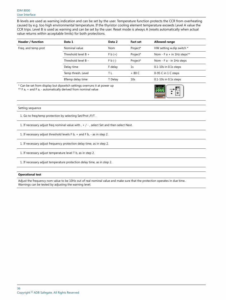
B-levels are used as warning indication and can be set by the user. Temperature function protects the CCR from overheatingcaused by e.g. too high environmental temperature. If the thyristor cooling element temperature exceeds Level A value theCCR trips. Level B is used as warning and can be set by the user. Reset mode is always A (resets automatically when actualvalue returns within acceptable limits) for both protections.
Header / function Data 1 Data 2 Fact set Allowed range
Freq. and temp prot Nominal value Nom Project* HW setting w.dip switch *
Threshold level B + F b (+) Project* Nom - F a + in 1Hz steps**
Threshold level B – F b (-) Project* Nom - F a - in 1Hz steps
Delay time F delay 1s 0.1-10s in 0.1s steps
Temp thresh. Level T L + 80 C 0-95 C in 1 C steps
BTemp delay time T Delay 10s 0.1-10s in 0.1s steps
* Can be set from display but dipswitch settings overruns it at power up** F a, + and F a, - automatically derived from nominal value
Setting sequence
1. Go to freq/temp protection by selecting Set/Prot /F/T .
1. If necessary adjust freq nominal value with , + / - , select Set and then select Next.
1. If necessary adjust threshold levels F b, + and F b, - as in step 2.
1. If necessary adjust frequency protection delay time, as in step 2.
1. If necessary adjust temperature level T b, as in step 2.
1. If necessary adjust temperature protection delay time, as in step 2.
Operational test
Adjust the frequency nom value to be 10Hz out of real nominal value and make sure that the protection operates in due time.Warnings can be tested by adjusting the warning level.
IDM 8000User Interface
36Copyright © ADB Safegate, All Rights Reserved
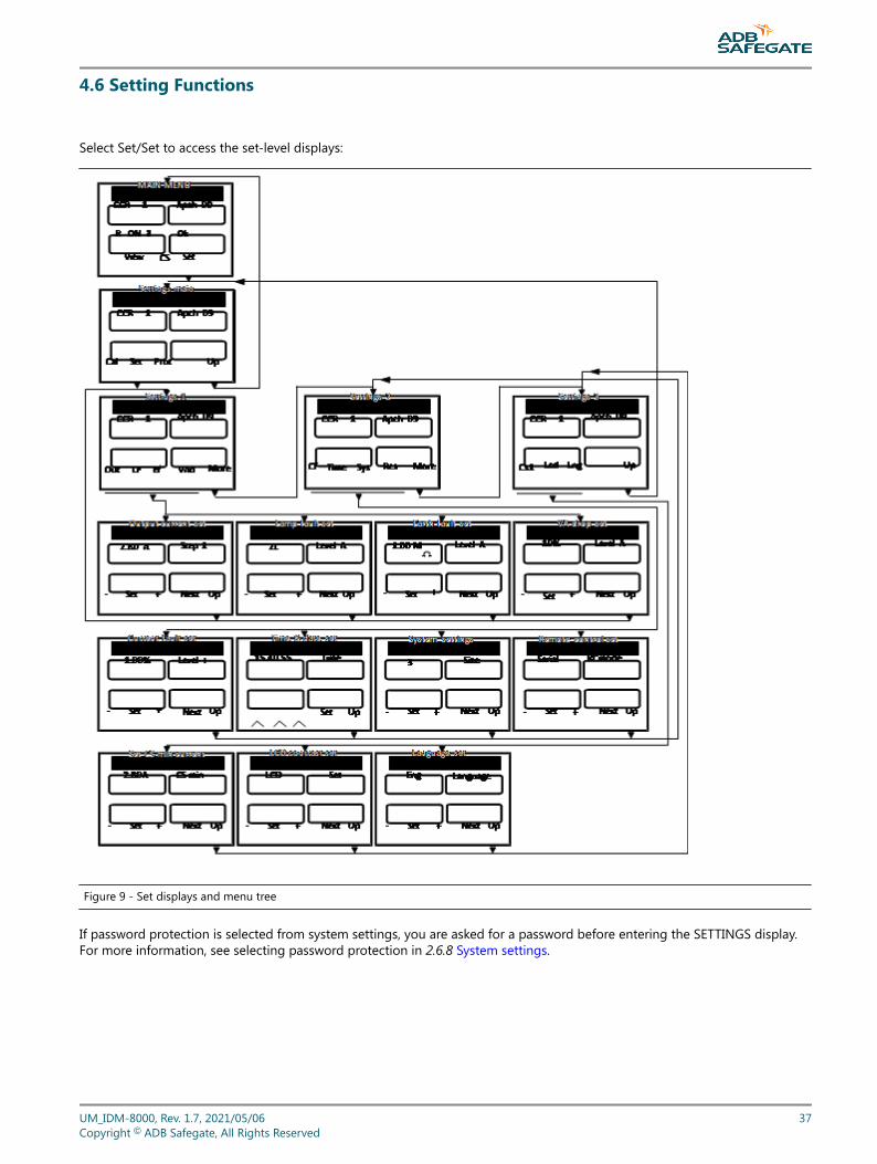
4.6 Setting Functions
Select Set/Set to access the set-level displays:
Figure 9 - Set displays and menu tree
If password protection is selected from system settings, you are asked for a password before entering the SETTINGS display.For more information, see selecting password protection in 2.6.8 System settings.
UM_IDM-8000, Rev. 1.7, 2021/05/06 37Copyright © ADB Safegate, All Rights Reserved
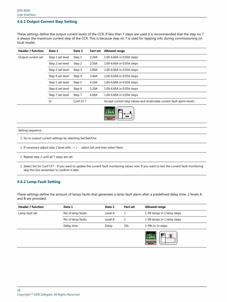
4.6.1 Output Current Step Setting
These settings define the output current levels of the CCR. If less than 7 steps are used it is recommended that the step no 7is always the maximum current step of the CCR. This is because step no 7 is used for tapping info during commissioning (inlocal mode).
Header / function Data 1 Data 2 Fact set Allowed range
Output current set Step 1 set level Step 1 2.20A 1.00-6.60A in 0.05A steps
Step 2 set level Step 2 2.50A 1.00-6.60A in 0.05A steps
Step 3 set level Step 3 2.80A 1.00-6.60A in 0.05A steps
Step 4 set level Step 4 3.40A 1.00-6.60A in 0.05A steps
Step 5 set level Step 5 4.10A 1.00-6.60A in 0.05A steps
Step 6 set level Step 6 5.20A 1.00-6.60A in 0.05A steps
Step 7 set level Step 7 6.60A 1.00-6.60A in 0.05A steps
I2 Conf CF ? Accept current step values and recalculate current fault alarm levels.
Setting sequence
1. Go to output current settings by selecting Set/Set/Out.
1. If necessary adjust step 1 level with , + / - , select Set and then select Next.
1. Repeat step 2 until all 7 steps are set.
1. Select Set for Conf CF? - If you want to update the current fault monitoring values now. If you want to test the current fault monitoringskip this but remember to confirm it later.
4.6.2 Lamp Fault Setting
These settings define the amount of lamps faults that generates a lamp fault alarm after a predefined delay time. 2 levels Aand B are provided.
Header / function Data 1 Data 2 Fact set Allowed range
Lamp fault set No of lamp faults Level A 2 1-99 lamps in 1 lamp steps
No of lamp faults Level B 1 1-99 lamps in 1 lamp steps
Delay time Delay 10s 1-99s in 1s steps
IDM 8000User Interface
38Copyright © ADB Safegate, All Rights Reserved
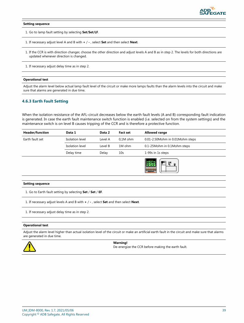
Setting sequence
1. Go to lamp fault setting by selecting Set/Set/LF.
1. If necessary adjust level A and B with + / - , select Set and then select Next.
1. If the CCR is with direction changer, choose the other direction and adjust levels A and B as in step 2. The levels for both directions areupdated whenever direction is changed.
1. If necessary adjust delay time as in step 2.
Operational test
Adjust the alarm level below actual lamp fault level of the circuit or make more lamps faults than the alarm levels into the circuit and makesure that alarms are generated in due time.
4.6.3 Earth Fault Setting
When the isolation resistance of the AFL-circuit decreases below the earth fault levels (A and B) corresponding fault indicationis generated. In case the earth fault maintenance switch function is enabled (i.e. selected on from the system settings) and themaintenance switch is on level B causes tripping of the CCR and is therefore a protective function.
Header/function Data 1 Data 2 Fact set Allowed range
Earth fault set Isolation level Level A 0,1M ohm 0.01-2.50Mohm in 0.01Mohm steps
Isolation level Level B 1M ohm 0.1-25Mohm in 0.1Mohm steps
Delay time Delay 10s 1-99s in 1s steps
Setting sequence
1. Go to Earth fault setting by selecting Set / Set / EF.
1. If necessary adjust levels A and B with + / - , select Set and then select Next.
1. If necessary adjust delay time as in step 2.
Operational test
Adjust the alarm level higher than actual isolation level of the circuit or make an artificial earth fault in the circuit and make sure that alarmsare generated in due time.
Warning!De-energize the CCR before making the earth fault.
UM_IDM-8000, Rev. 1.7, 2021/05/06 39Copyright © ADB Safegate, All Rights Reserved
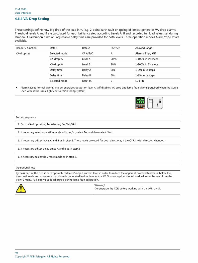
4.6.4 VA-Drop Setting
These settings define how big drop of the load in % (e.g. 2-point earth fault or ageing of lamps) generates VA-drop alarms.Threshold levels A and B are calculated for each brilliancy step according Levels A, B and recorded full load values set duringlamp fault calibration function. Adjustable delay times are provided for both levels. Three operation modes Alarm/trip/Off areavailable.
Header / function Data 1 Data 2 Fact set Allowed range
VA-drop set Selected mode VA A/T/O A Alarm / Trip / Off *
VA-drop % Level A 20 % 1-100% in 1% steps
VA-drop % Level B 10% 1-100% in 1% steps
Delay time Delay A 30s 1-99s in 1s steps
Delay time Delay B 30s 1-99s in 1s steps
Selected mode Reset m. L L / L+R
• Alarm causes normal alarms. Trip de-energizes output on level A. Off disables VA-drop and lamp fault alarms (required when the CCR isused with addressable light control/monitoring system)
Setting sequence
1. Go to VA-drop setting by selecting Set/Set/VAd.
1. If necessary select operation mode with , + / - , select Set and then select Next.
1. If necessary adjust levels A and B as in step 2. These levels are used for both directions, if the CCR is with direction changer.
1. If necessary adjust delay times A and B as in step 2.
1. If necessary select trip / reset mode as in step 2.
Operational test
By-pass part of the circuit or temporarily reduce I2 output current level in order to reduce the apparent power actual value below thethreshold levels and make sure that alarm is generated in due time. Actual VA % value against the full load value can be seen from theView/S menu. Full load value is calibrated during lamp fault calibration.
Warning!De-energize the CCR before working with the AFL-circuit.
IDM 8000User Interface
40Copyright © ADB Safegate, All Rights Reserved
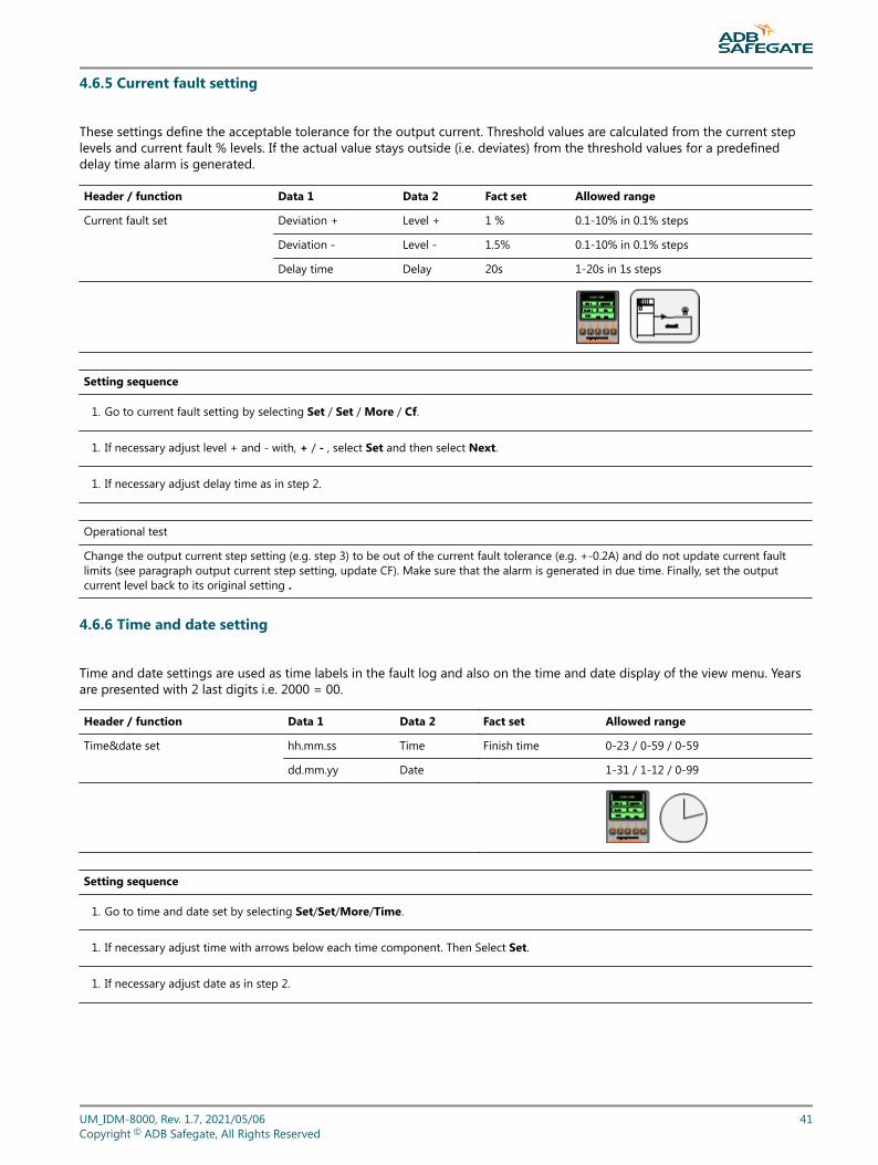
4.6.5 Current fault setting
These settings define the acceptable tolerance for the output current. Threshold values are calculated from the current steplevels and current fault % levels. If the actual value stays outside (i.e. deviates) from the threshold values for a predefineddelay time alarm is generated.
Header / function Data 1 Data 2 Fact set Allowed range
Current fault set Deviation + Level + 1 % 0.1-10% in 0.1% steps
Deviation - Level - 1.5% 0.1-10% in 0.1% steps
Delay time Delay 20s 1-20s in 1s steps
Setting sequence
1. Go to current fault setting by selecting Set / Set / More / Cf.
1. If necessary adjust level + and - with, + / - , select Set and then select Next.
1. If necessary adjust delay time as in step 2.
Operational test
Change the output current step setting (e.g. step 3) to be out of the current fault tolerance (e.g. +-0.2A) and do not update current faultlimits (see paragraph output current step setting, update CF). Make sure that the alarm is generated in due time. Finally, set the outputcurrent level back to its original setting .
4.6.6 Time and date setting
Time and date settings are used as time labels in the fault log and also on the time and date display of the view menu. Yearsare presented with 2 last digits i.e. 2000 = 00.
Header / function Data 1 Data 2 Fact set Allowed range
Time&date set hh.mm.ss Time Finish time 0-23 / 0-59 / 0-59
dd.mm.yy Date 1-31 / 1-12 / 0-99
Setting sequence
1. Go to time and date set by selecting Set/Set/More/Time.
1. If necessary adjust time with arrows below each time component. Then Select Set.
1. If necessary adjust date as in step 2.
UM_IDM-8000, Rev. 1.7, 2021/05/06 41Copyright © ADB Safegate, All Rights Reserved
4.6.7 Hardware system settings
These are the basic settings of the CCR. The settings will be read from the 8-bit dip-switch located next to the MCU cardconnector on the mother board whenever the CCR is powered up.
Dec code 0 enables setting from display e.g. for protection testing purposes.
These factory settings enable the MCU card to automatically detect the basic settings of the CCR and need only to bechanged/checked when modifying the CCR type or replacing a new mother board.
IDM 8000User Interface
42Copyright © ADB Safegate, All Rights Reserved
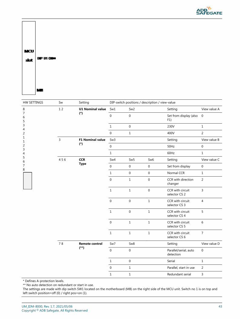
HW SETTINGS Sw Setting DIP-switch positions / description / view-value
8 7 6 5 3 4 2 1 1 2 3 4 5 6 7 8
1 2 U1 Nominal value(*)
Sw1 Sw2 Setting View value A
0 0 Set from display (alsoF1)
0
1 0 230V 1
0 1 400V 2
3 F1 Nominal value(*)
Sw3 Setting View value B
0 50Hz 0
1 60Hz 1
4 5 6 CCRType
Sw4 Sw5 Sw6 Setting View value C
0 0 0 Set from display 0
1 0 0 Normal CCR 1
0 1 0 CCR with directionchanger
2
1 1 0 CCR with circuitselector CS 2
3
0 0 1 CCR with circuitselector CS 3
4
1 0 1 CCR with circuitselector CS 4
5
0 1 1 CCR with circuitselector CS 5
6
1 1 1 CCR with circuitselector CS 6
7
7 8 Remote control(**)
Sw7 Sw8 Setting View value D
0 0 Parallel/serial, autodetection
0
1 0 Serial 1
0 1 Parallel, start in use 2
1 1 Redundant serial 3
* Defines A-protection levels.** No auto detection on redundant or start in use.The settings are made with dip switch SW1 located on the motherboard (MB) on the right side of the MCU unit. Switch no 1 is on top andleft switch position=off (0) / right pos=on (1).
UM_IDM-8000, Rev. 1.7, 2021/05/06 43Copyright © ADB Safegate, All Rights Reserved
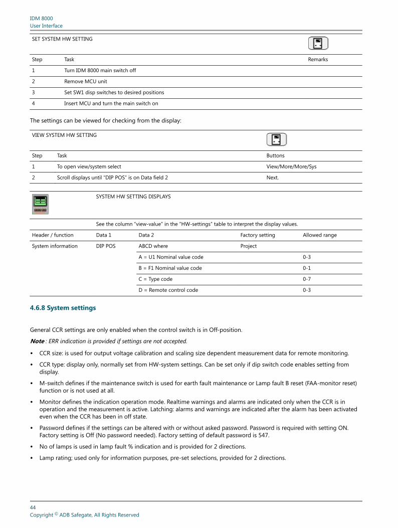
SET SYSTEM HW SETTING
Step Task Remarks
1 Turn IDM 8000 main switch off
2 Remove MCU unit
3 Set SW1 disp switches to desired positions
4 Insert MCU and turn the main switch on
The settings can be viewed for checking from the display:
VIEW SYSTEM HW SETTING
Step Task Buttons
1 To open view/system select View/More/More/Sys
2 Scroll displays until “DIP POS” is on Data field 2 Next.
SYSTEM HW SETTING DISPLAYS
See the column “view-value” in the “HW-settings” table to interpret the display values.
Header / function Data 1 Data 2 Factory setting Allowed range
System information DIP POS ABCD where Project
A = U1 Nominal value code 0-3
B = F1 Nominal value code 0-1
C = Type code 0-7
D = Remote control code 0-3
4.6.8 System settings
General CCR settings are only enabled when the control switch is in Off-position.
Note : ERR indication is provided if settings are not accepted.
• CCR size: is used for output voltage calibration and scaling size dependent measurement data for remote monitoring.
• CCR type: display only, normally set from HW-system settings. Can be set only if dip switch code enables setting fromdisplay.
• M-switch defines if the maintenance switch is used for earth fault maintenance or Lamp fault B reset (FAA-monitor reset)function or is not used at all.
• Monitor defines the indication operation mode. Realtime warnings and alarms are indicated only when the CCR is inoperation and the measurement is active. Latching: alarms and warnings are indicated after the alarm has been activatedeven when the CCR has been in off state.
• Password defines if the settings can be altered with or without asked password. Password is required with setting ON.Factory setting is Off (No password needed). Factory setting of default password is 547.
• No of lamps is used in lamp fault % indication and is provided for 2 directions.
• Lamp rating; used only for information purposes, pre-set selections, provided for 2 directions.
IDM 8000User Interface
44Copyright © ADB Safegate, All Rights Reserved
• CCR number: CCRs control system position number. With 2 below information fields used as a name label of the CCR onthe main menu display. If CCR number is set to “0”, the name label is not shown on the display. Instead the output currentand voltage is viewed in MAIN MENU.
• Position text: circuit name selectable from:
Abbreviation Circuit / lighting system
APCH Approach lighting system
THR Threshold lighting system
PAPI Precision approach path indicator system
RWYE Runway edge light system
RCL Runway centre line light system
TDZ Touchdown lighting system
TWYE Taxiway edge lighting system
TCL Taxiway centre line lighting system
SB Stop-bar lighting system
RGL Runway guard lights
SIGN Guidance signs
Not displayed
• CCR direction: CCR control (i.e. runway) direction (2 directions) or taxiway number.
• Lamp life: Set the time to be monitored for operational lamp life. When the total operation time of the CCR reaches Lamplife value, an alarm LAMP_AGE will be given to local indication. Also the ComF indication is given if selected as SumF-indication. For more information, see 2.6.9 Remote control settings. The indication is reset by resetting the operatinghours counter from the View-Hrs menu. Also the indication is reset automatically if the lamp life parameter is increased isthis menu.
• Service date: Used to memorize date of last CCR service / calibration.
Header / function Data 1 Data 2 Fact set Allowed range
System settings CCR sizeCCR typeEf. Maint switchIndication typeON/OFFNo of lampsLamp ratingEF ScaleCCR numberCircuit nameCCR cntrl dirHours for lampsCCR serv. Date
SizeTypeM-switchMonitorPasswordLampsLamp pwrEF RangeCCRTextDirLamplifeLst serv
Project*Project*Project*RealtimeOFF1045W50MProject*Project*Project*OffFtest date
0-30kVA from listDisplay onlyNo / Efm / LF1Realtime / LatchingOFF / ON (fs pw: 547 )1-1000 in 1 lamp steps45-300W from list50M / 1G0-99APCH-SIGN, “ “01-36, 0 = not used “ “Off,100,200…20 000Set records current date
UM_IDM-8000, Rev. 1.7, 2021/05/06 45Copyright © ADB Safegate, All Rights Reserved
Setting sequence
1. Go to system settings by selecting Set/Set/More/Sys.
1. Browse the desired parameter with Next, adjust it with + / - and select Set to confirm.
1. If the CCR is with direction changer, select the other direction and set required parameters.
4.6.9 Remote control settings
These general remote control settings are only enabled when the control switch is in Off-position.
Note : ERR indication is provided if settings are not accepted.
The CCR automatically detects if serial or parallel or no remote control card is connected and provides setting menusaccordingly:
• Rcmode: Display only, serial (computerized) or parallel control card or no card detected.
• Bustype: Serial mode only. Displays which type of fieldbus card is detected (e.g. Profibus)
• Fieldb: Serial mode only, tells if 1 or 2 (redundant system) serial cards are detected
• Fails: Serial mode only. Failsafe mode i.e. what happens in case of bus failure:
Setting Function
Cont Continues with selected control status
Fs Selects the failsafe step 0-7 (failsafe)
Fs off Selects the failsafe step only if control status is Off, else continues with selected control stat.
ContHB Continues with selected control status, Heart beat signal is used for bus failure detection.
Fs HB Selects the failsafe step 0-7 (failsafe), Heart beat signal is used for bus failure detection.
Fs of HB Selects the failsafe step only if control status is Off, else continues with selected control stat. Heart beat signal is used for busfailure detection.
In case of direction changer CCR dir 1 is considered as failsafe direction and all circuits with circuit selector CCRs.
• F step: Serial mode only. Select a failsafe step if Fs or Fs off modes are selected
• Dec/bin: parallel mode only: coding of control signals.
• Cont/imp: parallel mode only: mode of control signals
• ComF-m: defines if all fault signals are summed to Com-fault indication (SumF) or it contains only U1, f1 and T alarms(SysF).
Displays with serial remote control card detected:
Header / function Data 1 Data 2 Fact set Allowed range
Remote control set Serial/ none Rcmode * Project Autodetect
Bustype Bustype * Project Autodetect
No of serial cards Fieldb * Project Autodetect
Failsafe mode Fails Cont Cont / Fs / Fs off / ContHB / FS HB / FsofHB
Failsafe step F step 00 0-7
IDM 8000User Interface
46Copyright © ADB Safegate, All Rights Reserved
Displays with parallel remote control card or no card detected:
Header / function Data 1 Data 2 Fact set Allowed range
Remote control set Serial/parallel cntrl RCMODE Auto detect: parallel / none
Signal coding Dec/Bin Dec Dec/bin
Signal mode Cont/imp Cont Cont / imp
Com fault content ComF-m SysF SysF / SumF
Setting sequence
1. Set the control switch in Off-position.
1. Go to remote control settings by selecting Set /Set /More/Rcs.
1. Browse the desired parameter with Next, adjust it with , + / - and select Set to confirm.
4.6.10 Circuit selector minimum current setting
This setting defines the reduced output current of the CCR when disconnecting loads with the circuit selector. Optimal settingcauses minimum flickering of lights without overshooting the output current when disconnecting loads with the circuitselector.
Note : Factory setting is minimum current with short circuit load. If more than one circuit is active, ERR indication is displayed.
Header / function Data 1 Data 2 Fact set Allowed range
Set Cs min current I2 / A CS MIN Short Loads CS1-CS4 (only one)Set / Min
Setting sequence
1. Select the smallest of the circuit selector loads CS1-CS4. Use U2 View display to check which one is smallest (smallest U2 means smallestload).
1. Select Set/Set/More/CSI to go to circuit selector minimum current setting .
1. Select the desired current level with the local operation switch e.g. step 6.
1. Select Set to store the setting into memory and select Min to reset to a safe value.
UM_IDM-8000, Rev. 1.7, 2021/05/06 47Copyright © ADB Safegate, All Rights Reserved
4.6.11 LCD contrast setting
This setting defines the contrast of the LC-display which may need to be adjusted according the desired viewing angle andprevailing room temperature.
Header / function Data 1 Data 2 Fact set Allowed range
LCD contrast set Contrast value LCDSET 12 0-25 contrast range, 0=max
Setting sequence
1. Go to LCD contrast setting by selecting Set/Set/More/More/Lcd.
1. Adjust contrast value with , + / - and select Set to confirm.
1. If setting is not enough to make the contrast visible, see ../concepts/IDM-8000_troubleshooting.dita.
4.6.12 Language setting
Display language for the header and soft key texts can be selected between.
Standard English characters are used.
Header / function Data 1 Data 2 Fact set Allowed range
Language set Eng Language eng Eng / fin / swe / pol / spa / fra
Setting sequence
1. Go to language setting by selecting Set/Set/More/More/Lng.
1. Choose language with + / - ,and select Set to confirm.
IDM 8000User Interface
48Copyright © ADB Safegate, All Rights Reserved
5.0 Installation
5.1 General
This section deals with the installation of the CCR. Please refer to specific wiring diagrams and mechanic drawings for detailedinformation.
5.1.1 Air conditioning
NOTICEMake sure you use air conditioning to reduce the risk of equipment damage!
The table below lists the heat dissipation values of the CCR:
Table 1: Air conditioning relevant valuesPower Rating Heat Dissipation (W)
3 kVA 300
4 kVA 400
5 kVA 500
7.5 kVA 750
10 kVA 1000
12.5 kVA 1250
15 kVA 1400
17.5 kVA 1500
20 kVA 1600
25 kVA 2000
30 kVA 2400
5.1.2 Transportation, Unpacking and Storage
Transportation
Make sure to do the following regarding transportation:
NOTICEKeep the CCR always in upright position during transportation and storage.Protect the CCR from adverse weather conditions.
Make sure to do the following upon receipt:
UM_IDM-8000, Rev. 1.7, 2021/05/06 49Copyright © ADB Safegate, All Rights Reserved
Unpacking
1. Unpack and inspect the equipment immediately.
2. Check the packing and equipment itself for damage.
RememberNotify the carrier if of any damages.
Storage
RestrictionMake sure you follow the following guidelines regarding the sotrageDo not store the equipment for a prolongedperiod inside its packaging. It shall not be stored in an environment which do not respect the environmentalconditions defined for its use in section 1.2.3.
Transportation
Make sure to do the following regarding transportation:
NOTICEKeep the CCR always in upright position during transportation and storage.Protect the CCR from adverse weather conditions.
Unpacking
Make sure to do the following upon receipt:
1. Unpack and inspect the equipment immediately.
2. Check the packing and equipment itself for damage.
RememberNotify the carrier if of any damages.
Storage
RestrictionDo not store the equipment for a prolonged period in its packaging.Do not store the equipment in an environment which does not comply with the environmental conditions defined forits use in Environmental section.
NOTICEFor long term storage, it is recommended to keep the equipment in a dry (<60% humidity) and moderatetemperature area (15 - 30° C ambient temperature).It also recommended to regular inspect the equipment.After long storage it is recommended to inspect the equipment to clean it if necessary and to remove trace ofoxidation if any on electrical contact before connection.
Make sure to do the following regarding storage:
1. Inspect the equipment regularly.
IDM 8000Installation
50Copyright © ADB Safegate, All Rights Reserved
TipDefine a fixed time interval for inspection.
2. Do the following after a long storage period:
• Clean the equipment, if necessary.
• Remove the oxidation layer from the electrical contact before connection, if necessary.
5.1.3 Moving and Handling the CCR at Site
10 cm elevation of the bottom plate is provided to enable use of forklifts.
Keep the CCR always in upright position as it contains heavy components and fixing is designed for upright position only.
5.1.4 Installation Requirements
Fast pathMake sure that you install the CCR in a well-ventilated environment with sufficient clearances to walls and otherobjects. This way you ensure proper ventilation and smooth workflows in case of operation / maintenance tasks.
Table 2: Heat dissipation for air conditioning calculationVersion Value (W)
3 kVA 300 W
4 kVA 400 W
5 kVA 500 W
7.5 kVA 750 W
10 kVA 1000 W
12.5 kVA 1250 W
15 kVA 1400 W
17.5 kVA 1500 W
20 kVA 1600 W
25 kVA 2000 W
30 kVA 2400 W
5.2 Mechanical Installation
• All cable entries are through the bottom plate of the CCR.
• Leave 20cm clearance from wall and 50cm between CCR rows (back to back installation) for proper ventilation space.
• Reserve sufficient clearance in the front of the CCR for maintenance and operation purposes.
5.3 Electrical Installation
UM_IDM-8000, Rev. 1.7, 2021/05/06 51Copyright © ADB Safegate, All Rights Reserved
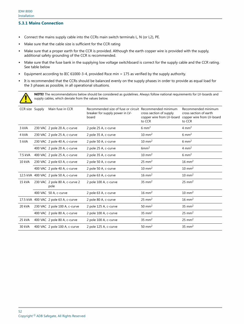
5.3.1 Mains Connection
• Connect the mains supply cable into the CCRs main switch terminals L, N (or L2), PE.
• Make sure that the cable size is sufficient for the CCR rating
• Make sure that a proper earth for the CCR is provided. Although the earth copper wire is provided with the supply,additional safety grounding of the CCR is recommended.
• Make sure that the fuse bank in the supplying low voltage switchboard is correct for the supply cable and the CCR rating.See table below
• Equipment according to IEC 61000-3-4, provided Rsce min = 175 as verified by the supply authority.
• It is recommended that the CCRs should be balanced evenly on the supply phases in order to provide as equal load forthe 3 phases as possible, in all operational situations.
NOTE! The recommendations below should be considered as guidelines. Always follow national requirements for LV-boards andsupply cables, which deviate from the values below.
CCR size Supply Main fuse in CCR Recommended size of fuse or circuitbreaker for supply power in LV-board
Recommended minimumcross section of supplycopper wire from LV-boardto CCR
Recommended minimumcross section of earthcopper wire from LV-boardto CCR
3 kVA 230 VAC 2 pole 20 A, c-curve 2 pole 25 A, c-curve 6 mm2 4 mm2
4 kVA 230 VAC 2 pole 25 A, c-curve 2 pole 35 A, c-curve 10 mm2 6 mm2
5 kVA 230 VAC 2 pole 40 A, c-curve 2 pole 50 A, c-curve 10 mm2 6 mm2
400 VAC 2 pole 20 A, c-curve 2 pole 25 A, c-curve 6mm2 4 mm2
7.5 kVA 400 VAC 2 pole 25 A, c-curve 2 pole 35 A, c-curve 10 mm2 6 mm2
10 kVA 230 VAC 2 pole 63 A, c-curve 2 pole 50 A, c-curve 25 mm2 16 mm2
400 VAC 2 pole 40 A, c-curve 2 pole 50 A, c-curve 10 mm2 10 mm2
12.5 kVA 400 VAC 2 pole 50 A, c-curve 2 pole 63 A, c-curve 16 mm2 10 mm2
15 kVA 230 VAC 2 pole 80 A, c-curve 2pole
2 pole 100 A, c-curve 35 mm2 25 mm2
400 VAC 50 A, c-curve 2 pole 63 A, c-curve 16 mm2 10 mm2
17.5 kVA 400 VAC 2 pole 63 A, c-curve 2 pole 80 A, c-curve 25 mm2 16 mm2
20 kVA 230 VAC 2 pole 100 A, c-curve 2 pole 125 A, c-curve 50 mm2 35 mm2
400 VAC 2 pole 80 A, c-curve 2 pole 100 A, c-curve 35 mm2 25 mm2
25 kVA 400 VAC 2 pole 80 A, c-curve 2 pole 100 A, c-curve 35 mm2 25 mm2
30 kVA 400 VAC 2 pole 100 A, c-curve 2 pole 125 A, c-curve 50 mm2 35 mm2
IDM 8000Installation
52Copyright © ADB Safegate, All Rights Reserved
5.3.2 AFL-Circuit Connection
• Connect each circuit to pair of terminals marked with capital and small characters (e.g. A, a)
• If more circuits than one is used the connectors are in alphabetical order i.e. circuit 1 = A, a, circuit 2 = B, b etc.
• If grounding is used connect the cable shields to the grounding terminals on the cable fixing rail of the high voltagecompartment.
5.3.3 Serial Remote Control Connection
• Connect the bus cable with D9 connector directly on the face of the serial control card.
Note : Make sure that the connector is designed for that specific bustype (e.g. Profibus). For more information, see Appendix A –Serial communication interface – Profibus DP connection. If the connectors have termination switches, make sure their settingsconform to bus configuration (normally first and last physical units are terminated. Remember that there are terminationswitches on the serial control cards too!). It is recommended to use the termination in the cable connector to be able to replaceany unit without affecting the bus operation. Make sure that the node address setting conforms to the bus configuration.
5.3.4 Parallel Remote Control Connection
• Connect the parallel control cable directly on the D37 connector located on the face of the card. For more information, seeAppendix E – Parallel control interface signal list.
• Optionally IDM8000 can be delivered with terminal block-connections inside the low voltage compartment. The signalconnection details are equal to the D37 connector.
Note : Before connecting, check that the remote control voltage setting conforms to the control voltage used.
5.4 Load matching
Load matching is provided from 45% to 100% with 5% and 10% taps on the Main Transformer. Benefits of load matching isdescribed in section 1.3.3 Main Transformer, Efficiency and Power Factor.
UM_IDM-8000, Rev. 1.7, 2021/05/06 53Copyright © ADB Safegate, All Rights Reserved
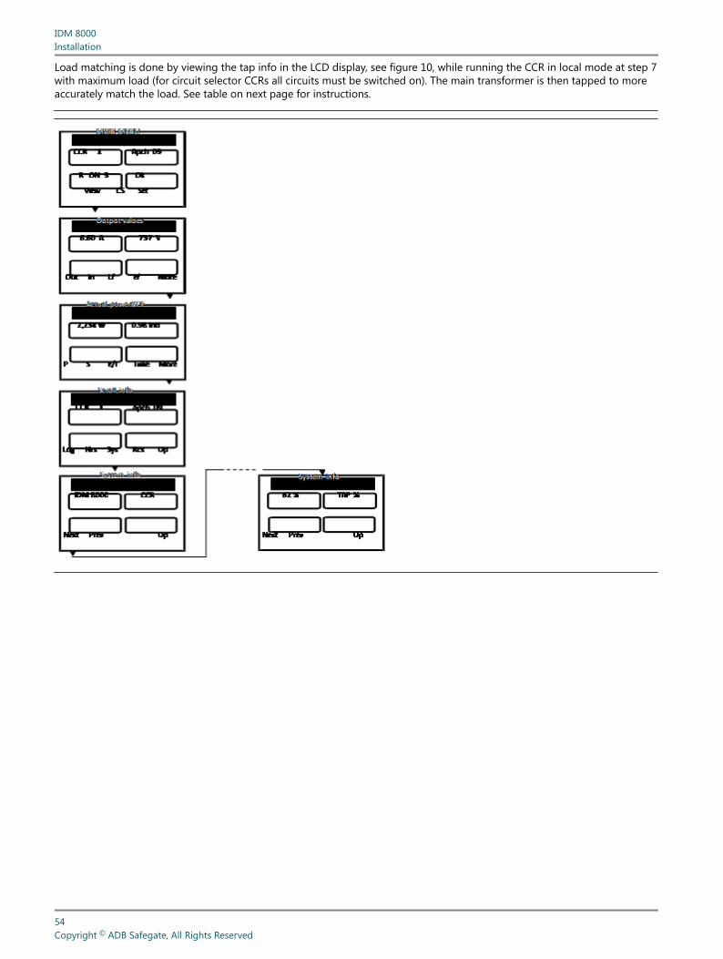
Load matching is done by viewing the tap info in the LCD display, see figure 10, while running the CCR in local mode at step 7with maximum load (for circuit selector CCRs all circuits must be switched on). The main transformer is then tapped to moreaccurately match the load. See table on next page for instructions.
IDM 8000Installation
54Copyright © ADB Safegate, All Rights Reserved
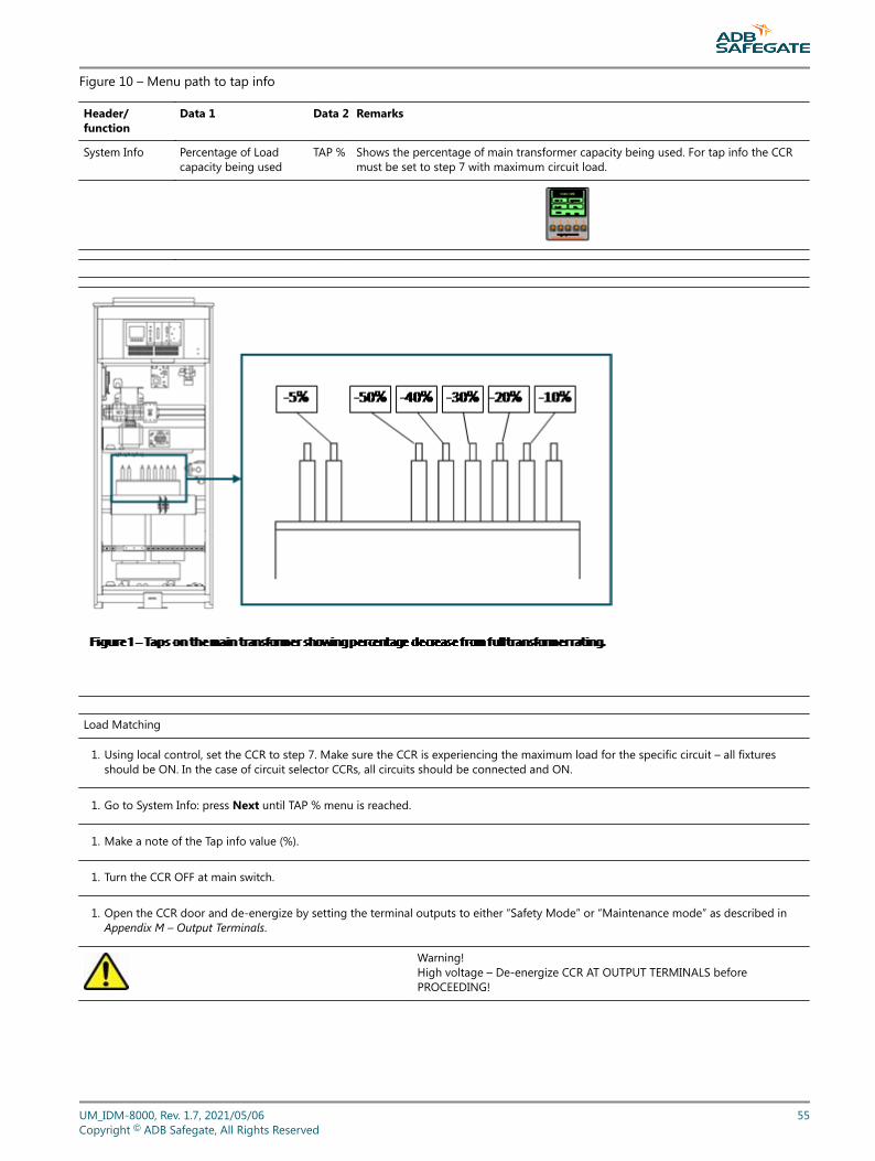
Figure 10 – Menu path to tap info
Header/function
Data 1 Data 2 Remarks
System Info Percentage of Loadcapacity being used
TAP % Shows the percentage of main transformer capacity being used. For tap info the CCRmust be set to step 7 with maximum circuit load.
Load Matching
1. Using local control, set the CCR to step 7. Make sure the CCR is experiencing the maximum load for the specific circuit – all fixturesshould be ON. In the case of circuit selector CCRs, all circuits should be connected and ON.
1. Go to System Info: press Next until TAP % menu is reached.
1. Make a note of the Tap info value (%).
1. Turn the CCR OFF at main switch.
1. Open the CCR door and de-energize by setting the terminal outputs to either “Safety Mode” or “Maintenance mode” as described inAppendix M – Output Terminals.
Warning!High voltage – De-energize CCR AT OUTPUT TERMINALS beforePROCEEDING!
UM_IDM-8000, Rev. 1.7, 2021/05/06 55Copyright © ADB Safegate, All Rights Reserved
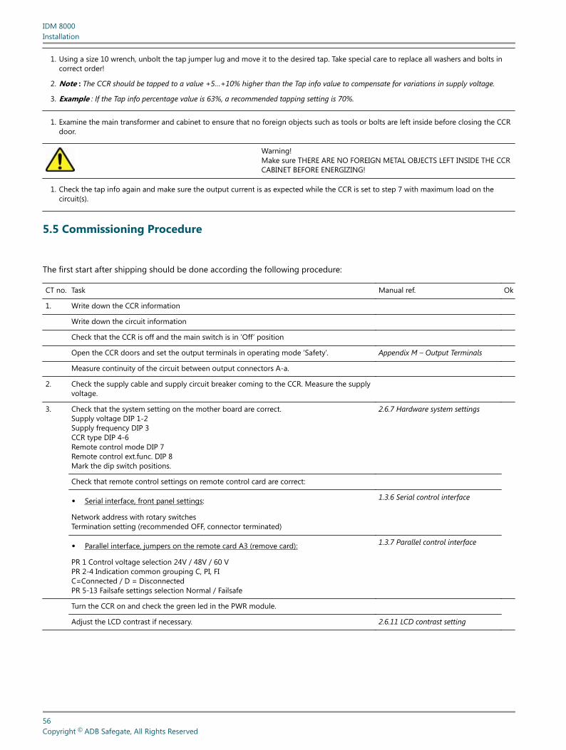
1. Using a size 10 wrench, unbolt the tap jumper lug and move it to the desired tap. Take special care to replace all washers and bolts incorrect order!
2. Note : The CCR should be tapped to a value +5…+10% higher than the Tap info value to compensate for variations in supply voltage.
3. Example : If the Tap info percentage value is 63%, a recommended tapping setting is 70%.
1. Examine the main transformer and cabinet to ensure that no foreign objects such as tools or bolts are left inside before closing the CCRdoor.
Warning!Make sure THERE ARE NO FOREIGN METAL OBJECTS LEFT INSIDE THE CCRCABINET BEFORE ENERGIZING!
1. Check the tap info again and make sure the output current is as expected while the CCR is set to step 7 with maximum load on thecircuit(s).
5.5 Commissioning Procedure
The first start after shipping should be done according the following procedure:
CT no. Task Manual ref. Ok
1. Write down the CCR information
Write down the circuit information
Check that the CCR is off and the main switch is in ’Off’ position
Open the CCR doors and set the output terminals in operating mode ’Safety’. Appendix M – Output Terminals
Measure continuity of the circuit between output connectors A-a.
2. Check the supply cable and supply circuit breaker coming to the CCR. Measure the supplyvoltage.
3. Check that the system setting on the mother board are correct.Supply voltage DIP 1-2Supply frequency DIP 3CCR type DIP 4-6Remote control mode DIP 7Remote control ext.func. DIP 8Mark the dip switch positions.
2.6.7 Hardware system settings
Check that remote control settings on remote control card are correct:
• Serial interface, front panel settings:
Network address with rotary switchesTermination setting (recommended OFF, connector terminated)
1.3.6 Serial control interface
• Parallel interface, jumpers on the remote card A3 (remove card):
PR 1 Control voltage selection 24V / 48V / 60 VPR 2-4 Indication common grouping C, PI, FIC=Connected / D = DisconnectedPR 5-13 Failsafe settings selection Normal / Failsafe
1.3.7 Parallel control interface
Turn the CCR on and check the green led in the PWR module.
Adjust the LCD contrast if necessary. 2.6.11 LCD contrast setting
IDM 8000Installation
56Copyright © ADB Safegate, All Rights Reserved
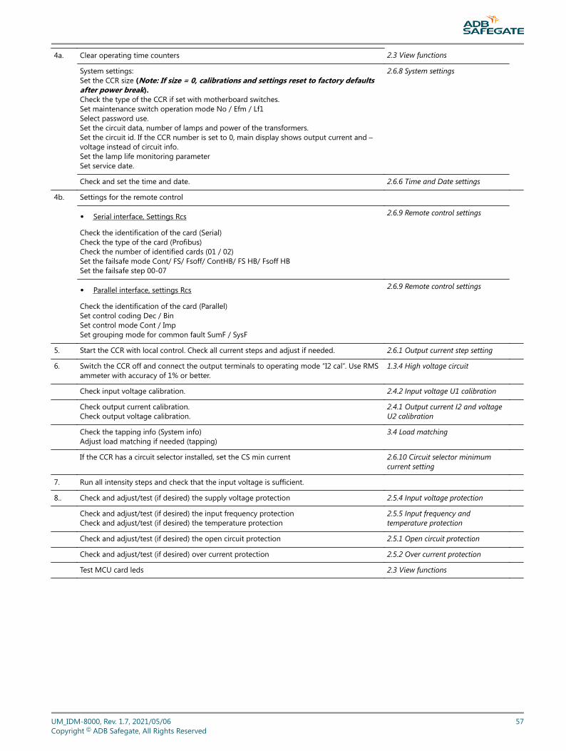
4a. Clear operating time counters 2.3 View functions
System settings:Set the CCR size (Note: If size = 0, calibrations and settings reset to factory defaultsafter power break).Check the type of the CCR if set with motherboard switches.Set maintenance switch operation mode No / Efm / Lf1Select password use.Set the circuit data, number of lamps and power of the transformers.Set the circuit id. If the CCR number is set to 0, main display shows output current and –voltage instead of circuit info.Set the lamp life monitoring parameterSet service date.
2.6.8 System settings
Check and set the time and date. 2.6.6 Time and Date settings
4b. Settings for the remote control
• Serial interface, Settings Rcs
Check the identification of the card (Serial)Check the type of the card (Profibus)Check the number of identified cards (01 / 02)Set the failsafe mode Cont/ FS/ Fsoff/ ContHB/ FS HB/ Fsoff HBSet the failsafe step 00-07
2.6.9 Remote control settings
• Parallel interface, settings Rcs
Check the identification of the card (Parallel)Set control coding Dec / BinSet control mode Cont / ImpSet grouping mode for common fault SumF / SysF
2.6.9 Remote control settings
5. Start the CCR with local control. Check all current steps and adjust if needed. 2.6.1 Output current step setting
6. Switch the CCR off and connect the output terminals to operating mode “I2 cal”. Use RMSammeter with accuracy of 1% or better.
1.3.4 High voltage circuit
Check input voltage calibration. 2.4.2 Input voltage U1 calibration
Check output current calibration.Check output voltage calibration.
2.4.1 Output current I2 and voltageU2 calibration
Check the tapping info (System info)Adjust load matching if needed (tapping)
3.4 Load matching
If the CCR has a circuit selector installed, set the CS min current 2.6.10 Circuit selector minimumcurrent setting
7. Run all intensity steps and check that the input voltage is sufficient.
8.. Check and adjust/test (if desired) the supply voltage protection 2.5.4 Input voltage protection
Check and adjust/test (if desired) the input frequency protectionCheck and adjust/test (if desired) the temperature protection
2.5.5 Input frequency andtemperature protection
Check and adjust/test (if desired) the open circuit protection 2.5.1 Open circuit protection
Check and adjust/test (if desired) over current protection 2.5.2 Over current protection
Test MCU card leds 2.3 View functions
UM_IDM-8000, Rev. 1.7, 2021/05/06 57Copyright © ADB Safegate, All Rights Reserved
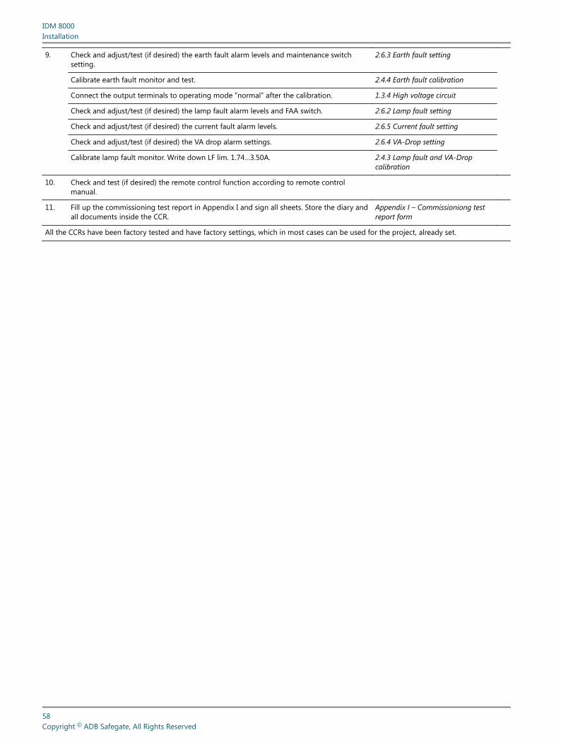
9. Check and adjust/test (if desired) the earth fault alarm levels and maintenance switchsetting.
2.6.3 Earth fault setting
Calibrate earth fault monitor and test. 2.4.4 Earth fault calibration
Connect the output terminals to operating mode ”normal” after the calibration. 1.3.4 High voltage circuit
Check and adjust/test (if desired) the lamp fault alarm levels and FAA switch. 2.6.2 Lamp fault setting
Check and adjust/test (if desired) the current fault alarm levels. 2.6.5 Current fault setting
Check and adjust/test (if desired) the VA drop alarm settings. 2.6.4 VA-Drop setting
Calibrate lamp fault monitor. Write down LF lim. 1.74…3.50A. 2.4.3 Lamp fault and VA-Dropcalibration
10. Check and test (if desired) the remote control function according to remote controlmanual.
11. Fill up the commissioning test report in Appendix I and sign all sheets. Store the diary andall documents inside the CCR.
Appendix I – Commissioniong testreport form
All the CCRs have been factory tested and have factory settings, which in most cases can be used for the project, already set.
IDM 8000Installation
58Copyright © ADB Safegate, All Rights Reserved
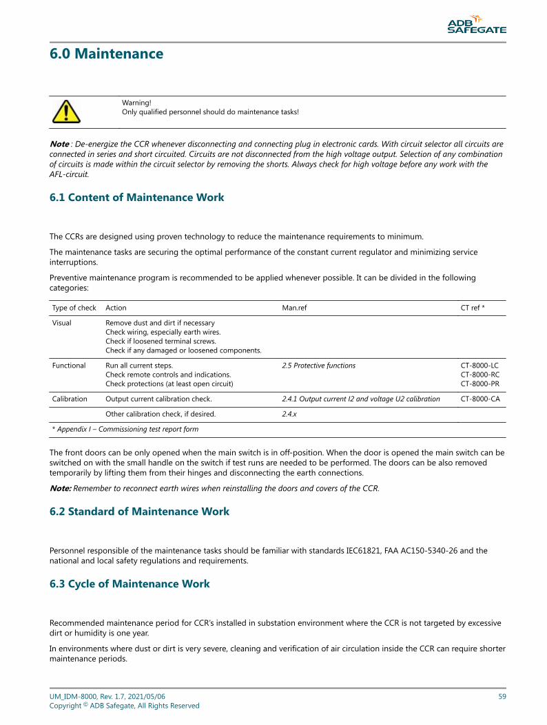
6.0 Maintenance
Warning!Only qualified personnel should do maintenance tasks!
Note : De-energize the CCR whenever disconnecting and connecting plug in electronic cards. With circuit selector all circuits areconnected in series and short circuited. Circuits are not disconnected from the high voltage output. Selection of any combinationof circuits is made within the circuit selector by removing the shorts. Always check for high voltage before any work with theAFL-circuit.
6.1 Content of Maintenance Work
The CCRs are designed using proven technology to reduce the maintenance requirements to minimum.
The maintenance tasks are securing the optimal performance of the constant current regulator and minimizing serviceinterruptions.
Preventive maintenance program is recommended to be applied whenever possible. It can be divided in the followingcategories:
Type of check Action Man.ref CT ref *
Visual Remove dust and dirt if necessaryCheck wiring, especially earth wires.Check if loosened terminal screws.Check if any damaged or loosened components.
Functional Run all current steps.Check remote controls and indications.Check protections (at least open circuit)
2.5 Protective functions CT-8000-LCCT-8000-RCCT-8000-PR
Calibration Output current calibration check. 2.4.1 Output current I2 and voltage U2 calibration CT-8000-CA
Other calibration check, if desired. 2.4.x
* Appendix I – Commissioning test report form
The front doors can be only opened when the main switch is in off-position. When the door is opened the main switch can beswitched on with the small handle on the switch if test runs are needed to be performed. The doors can be also removedtemporarily by lifting them from their hinges and disconnecting the earth connections.
Note: Remember to reconnect earth wires when reinstalling the doors and covers of the CCR.
6.2 Standard of Maintenance Work
Personnel responsible of the maintenance tasks should be familiar with standards IEC61821, FAA AC150-5340-26 and thenational and local safety regulations and requirements.
6.3 Cycle of Maintenance Work
Recommended maintenance period for CCR’s installed in substation environment where the CCR is not targeted by excessivedirt or humidity is one year.
In environments where dust or dirt is very severe, cleaning and verification of air circulation inside the CCR can require shortermaintenance periods.
UM_IDM-8000, Rev. 1.7, 2021/05/06 59Copyright © ADB Safegate, All Rights Reserved
Preventive maintenance program is recommended to be applied whenever possible.
6.4 Tools
There are no special tools required for maintenance or troubleshooting.
Below are listed some basic tools that are needed:
• True rms-reading current and voltmeter for calibration.
Screwdriver set including at least:
• Slotted 3x0.5, connectors for wires.
• Slotted 5.5x1.0, for contactors and circuit breakers.
• Slotted 8x1.2, door and main transformer connections.
• Pozidriv No 1, plug in units.
• Pozidriv No 2, length 160mm, mounting screws on installation plate.
Hexagon socket drivers:
• 10mm for output connectors.
• 8mm for housing.
• Hex Key set, metric, for supply and main transformer in larger CCRs.
• Torque wrench.
• Clean compressed air for cleaning dust or dirt
• CCR manual for correct operation procedures.
In addition to the maintenance tools:
• Spare parts for component replacement.
IDM 8000Maintenance
60Copyright © ADB Safegate, All Rights Reserved
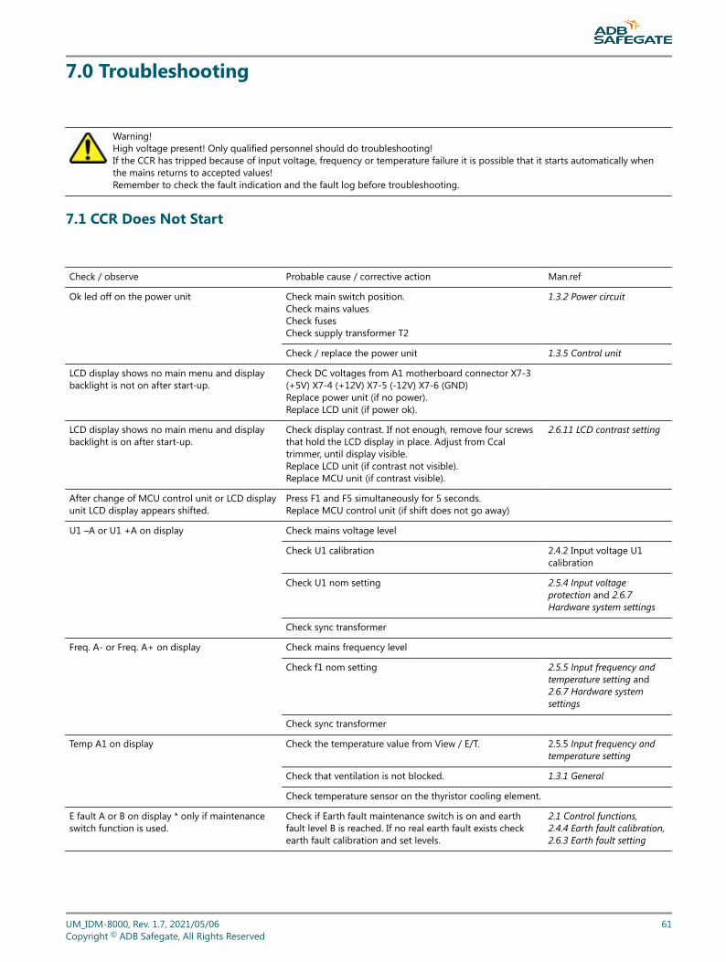
7.0 Troubleshooting
Warning!High voltage present! Only qualified personnel should do troubleshooting!If the CCR has tripped because of input voltage, frequency or temperature failure it is possible that it starts automatically whenthe mains returns to accepted values!Remember to check the fault indication and the fault log before troubleshooting.
7.1 CCR Does Not Start
Check / observe Probable cause / corrective action Man.ref
Ok led off on the power unit Check main switch position.Check mains valuesCheck fusesCheck supply transformer T2
1.3.2 Power circuit
Check / replace the power unit 1.3.5 Control unit
LCD display shows no main menu and displaybacklight is not on after start-up.
Check DC voltages from A1 motherboard connector X7-3(+5V) X7-4 (+12V) X7-5 (-12V) X7-6 (GND)Replace power unit (if no power).Replace LCD unit (if power ok).
LCD display shows no main menu and displaybacklight is on after start-up.
Check display contrast. If not enough, remove four screwsthat hold the LCD display in place. Adjust from Ccaltrimmer, until display visible.Replace LCD unit (if contrast not visible).Replace MCU unit (if contrast visible).
2.6.11 LCD contrast setting
After change of MCU control unit or LCD displayunit LCD display appears shifted.
Press F1 and F5 simultaneously for 5 seconds.Replace MCU control unit (if shift does not go away)
U1 –A or U1 +A on display Check mains voltage level
Check U1 calibration 2.4.2 Input voltage U1calibration
Check U1 nom setting 2.5.4 Input voltageprotection and 2.6.7Hardware system settings
Check sync transformer
Freq. A- or Freq. A+ on display Check mains frequency level
Check f1 nom setting 2.5.5 Input frequency andtemperature setting and2.6.7 Hardware systemsettings
Check sync transformer
Temp A1 on display Check the temperature value from View / E/T. 2.5.5 Input frequency andtemperature setting
Check that ventilation is not blocked. 1.3.1 General
Check temperature sensor on the thyristor cooling element.
E fault A or B on display * only if maintenanceswitch function is used.
Check if Earth fault maintenance switch is on and earthfault level B is reached. If no real earth fault exists checkearth fault calibration and set levels.
2.1 Control functions,2.4.4 Earth fault calibration,2.6.3 Earth fault setting
UM_IDM-8000, Rev. 1.7, 2021/05/06 61Copyright © ADB Safegate, All Rights Reserved
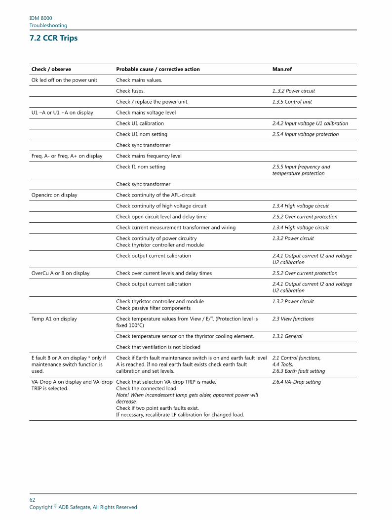
7.2 CCR Trips
Check / observe Probable cause / corrective action Man.ref
Ok led off on the power unit Check mains values.
Check fuses. 1..3.2 Power circuit
Check / replace the power unit. 1.3.5 Control unit
U1 –A or U1 +A on display Check mains voltage level
Check U1 calibration 2.4.2 Input voltage U1 calibration
Check U1 nom setting 2.5.4 Input voltage protection
Check sync transformer
Freq. A- or Freq. A+ on display Check mains frequency level
Check f1 nom setting 2.5.5 Input frequency andtemperature protection
Check sync transformer
Opencirc on display Check continuity of the AFL-circuit
Check continuity of high voltage circuit 1.3.4 High voltage circuit
Check open circuit level and delay time 2.5.2 Over current protection
Check current measurement transformer and wiring 1.3.4 High voltage circuit
Check continuity of power circuitryCheck thyristor controller and module
1.3.2 Power circuit
Check output current calibration 2.4.1 Output current I2 and voltageU2 calibration
OverCu A or B on display Check over current levels and delay times 2.5.2 Over current protection
Check output current calibration 2.4.1 Output current I2 and voltageU2 calibration
Check thyristor controller and moduleCheck passive filter components
1.3.2 Power circuit
Temp A1 on display Check temperature values from View / E/T. (Protection level isfixed 100°C)
2.3 View functions
Check temperature sensor on the thyristor cooling element. 1.3.1 General
Check that ventilation is not blocked
E fault B or A on display * only ifmaintenance switch function isused.
Check if Earth fault maintenance switch is on and earth fault levelA is reached. If no real earth fault exists check earth faultcalibration and set levels.
2.1 Control functions,4.4 Tools,2.6.3 Earth fault setting
VA-Drop A on display and VA-dropTRIP is selected.
Check that selection VA-drop TRIP is made.Check the connected load.Note! When incandescent lamp gets older, apparent power willdecrease.Check if two point earth faults exist.If necessary, recalibrate LF calibration for changed load.
2.6.4 VA-Drop setting
IDM 8000Troubleshooting
62Copyright © ADB Safegate, All Rights Reserved
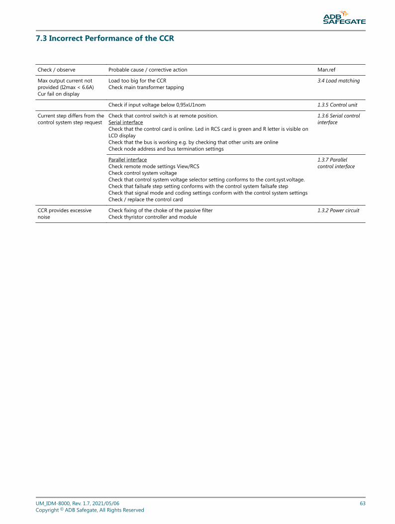
7.3 Incorrect Performance of the CCR
Check / observe Probable cause / corrective action Man.ref
Max output current notprovided (I2max < 6.6A)Cur fail on display
Load too big for the CCRCheck main transformer tapping
3.4 Load matching
Check if input voltage below 0,95xU1nom 1.3.5 Control unit
Current step differs from thecontrol system step request
Check that control switch is at remote position.Serial interfaceCheck that the control card is online. Led in RCS card is green and R letter is visible onLCD displayCheck that the bus is working e.g. by checking that other units are onlineCheck node address and bus termination settings
1.3.6 Serial controlinterface
Parallel interfaceCheck remote mode settings View/RCSCheck control system voltageCheck that control system voltage selector setting conforms to the cont.syst.voltage.Check that failsafe step setting conforms with the control system failsafe stepCheck that signal mode and coding settings conform with the control system settingsCheck / replace the control card
1.3.7 Parallelcontrol interface
CCR provides excessivenoise
Check fixing of the choke of the passive filterCheck thyristor controller and module
1.3.2 Power circuit
UM_IDM-8000, Rev. 1.7, 2021/05/06 63Copyright © ADB Safegate, All Rights Reserved

IDM 8000Troubleshooting
64Copyright © ADB Safegate, All Rights Reserved
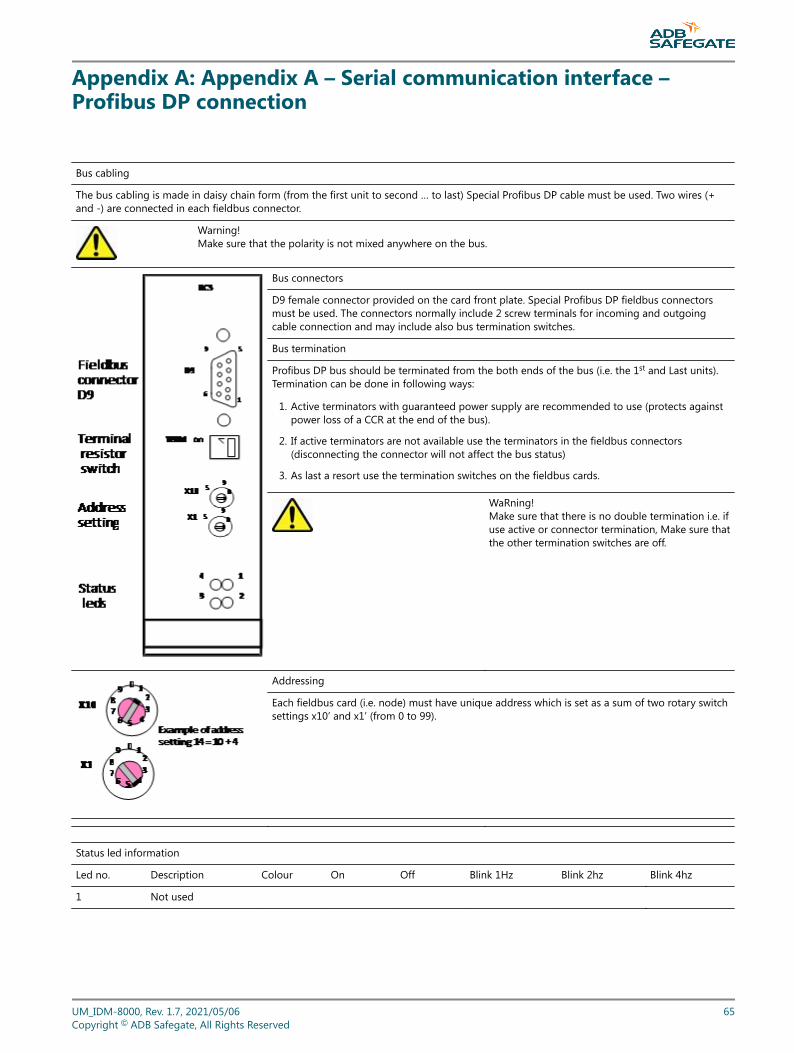
Appendix A: Appendix A – Serial communication interface –Profibus DP connection
Bus cabling
The bus cabling is made in daisy chain form (from the first unit to second … to last) Special Profibus DP cable must be used. Two wires (+and -) are connected in each fieldbus connector.
Warning!Make sure that the polarity is not mixed anywhere on the bus.
Bus connectors
D9 female connector provided on the card front plate. Special Profibus DP fieldbus connectorsmust be used. The connectors normally include 2 screw terminals for incoming and outgoingcable connection and may include also bus termination switches.
Bus termination
Profibus DP bus should be terminated from the both ends of the bus (i.e. the 1st and Last units).Termination can be done in following ways:
1. Active terminators with guaranteed power supply are recommended to use (protects againstpower loss of a CCR at the end of the bus).
2. If active terminators are not available use the terminators in the fieldbus connectors(disconnecting the connector will not affect the bus status)
3. As last a resort use the termination switches on the fieldbus cards.
WaRning!Make sure that there is no double termination i.e. ifuse active or connector termination, Make sure thatthe other termination switches are off.
Addressing
Each fieldbus card (i.e. node) must have unique address which is set as a sum of two rotary switchsettings x10’ and x1’ (from 0 to 99).
Status led information
Led no. Description Colour On Off Blink 1Hz Blink 2hz Blink 4hz
1 Not used
UM_IDM-8000, Rev. 1.7, 2021/05/06 65Copyright © ADB Safegate, All Rights Reserved

2 Online Green Online Offline N.A N.A N.A
3 Offline Red Offline Online N.A N.A N.A
4 Diagnostics Red N.A Ok Conf err. Parm.err. Init.err.
IDM 8000Appendix A – Serial communication interface – Profibus DP connection
66Copyright © ADB Safegate, All Rights Reserved
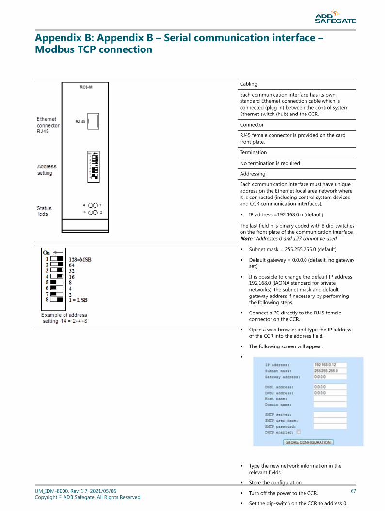
Appendix B: Appendix B – Serial communication interface –Modbus TCP connection
Cabling
Each communication interface has its ownstandard Ethernet connection cable which isconnected (plug in) between the control systemEthernet switch (hub) and the CCR.
Connector
RJ45 female connector is provided on the cardfront plate.
Termination
No termination is required
Addressing
Each communication interface must have uniqueaddress on the Ethernet local area network whereit is connected (including control system devicesand CCR communication interfaces).
• IP address =192.168.0.n (default)
The last field n is binary coded with 8 dip-switcheson the front plate of the communication interface.Note : Addresses 0 and 127 cannot be used.
• Subnet mask = 255.255.255.0 (default)
• Default gateway = 0.0.0.0 (default, no gatewayset)
• It is possible to change the default IP address192.168.0 (IAONA standard for privatenetworks), the subnet mask and defaultgateway address if necessary by performingthe following steps.
• Connect a PC directly to the RJ45 femaleconnector on the CCR.
• Open a web browser and type the IP addressof the CCR into the address field.
• The following screen will appear.
•
• Type the new network information in therelevant fields.
• Store the configuration.
• Turn off the power to the CCR.
• Set the dip-switch on the CCR to address 0.
• Turn on the power to the CCR.
• Test that the new IP address is valid.
• Note: Only the last digit of the default IPaddress 192.168.0.n can be set using the dip-switch. If the default IP address has beenchanged the dip-switch must remain set toaddress 0.
UM_IDM-8000, Rev. 1.7, 2021/05/06 67Copyright © ADB Safegate, All Rights Reserved
Status led information
Led no. Description Colour On Off Blink 1Hz Blink 2hz Blink 4hz
1 Link Activity Green Link No link ---------- ---------- ----------
2 ModuleStatus
Green ---------- --------- IP addr err ----------- -----------
Red Double IP addr. --------- Invalid MAC addr Ethernet cnfg.error Internal Err (fatal)
3 Network status Green No of Modbus established TCP connections = blinks / s
4 Activity Green Blinks each time data packet is transmitted
Power breaks
IDM 8000 equipped with single modbus TCP serial interface can manage 1s power breaks without any break on the control status. Whenreturning from longer power breaks the failsafe setting will be taken and hold until the serial interface is in online mode and starts followingthe control system commands. The start-up time varies depending on the network status from 1 to 3s.
IDM 8000Appendix B – Serial communication interface – Modbus TCP connection
68Copyright © ADB Safegate, All Rights Reserved

Appendix C: Appendix C – Serial control interface signal list –Profibus DP
Control bits:
Bit Byte Signal Remarks Bit Byte Signal Remarks
0 1 On a Off + 7 steps 4 1 Circ 2
1 On b * binary coding 5 Circ 3
2 On c * static 1= on 6 Circ 4
3 Dir 2/Circ 1 Acc. The CCR type 7 Hb Heartbeat bit
Indication bits:
Bit Byte Signal Remarks Bit Byte Signal Remarks
0 1 On ind a Off + 7 steps* binary coding* static 1= on
48 7 I2 / 0 I2 / Output current* 8A = 160* digit = 0,05A*resol = 0,6%* Lsb= I2 / 0
1 On ind b 49 I2 / 1
2 On ind c 50 I2 / 2
3 Dir 2 / Circ 1 0=dir 1, 1=dir 2 / Circ 1 on 51 I2 / 3
4 Circ 2 52 I2 / 4
5 Circ 3 53 I2 / 5
6 Circ 4 54 I2 / 6
7 Remote / Local Remote = 1 55 I2 / 7
8 2 Pwr on CCR powered 56 8 U2 / 0 U2 / Output voltage*resol = 0,8%*125=U2n (acc CCR size)* U2n = Pn / 6,6A* digit = U2n / 125* eg 3,63V / 3kVA CCR* Lsb= U2 / 0
9 Oc Over current alarm+fast I2 (1) 57 U2 / 1
10 Uc Open circuit alarm+SCO (2) 58 U2 / 2
11 U1 A Input voltage alarm ) 59 U2 / 3
12 U1 B Input voltage warning 60 U2 / 4
13 Freq A Input frequency alarm 61 U2 / 5
14 Freq B Input freq. Warning 62 U2 / 6
15 Temp A Thyrist temp alarm 63 U2 / 7
16 3 Temp B Thyrist temp warning 64 9 P2 / 0 P2 / Output actual power* 125 = Pn (acc CCR size)* digit = Pn / 125* eg 24W / 3kVA CCR* resol = 0,8%* Lsb= P2 / 0
17 VA-A VA-drop level A 65 P2 / 1
18 VA-B VA-drop level B 66 P2 / 2
19 Cf Current fault 67 P2 / 3
20 LF A Lamp fault alarm 68 P2 / 4
21 LF B Lamp fault warning 69 P2 / 5
22 EF A Earth fault alarm ( trip / m) 70 P2 / 6
23 EF B Earth fault warning 71 P2 / 7
UM_IDM-8000, Rev. 1.7, 2021/05/06 69Copyright © ADB Safegate, All Rights Reserved
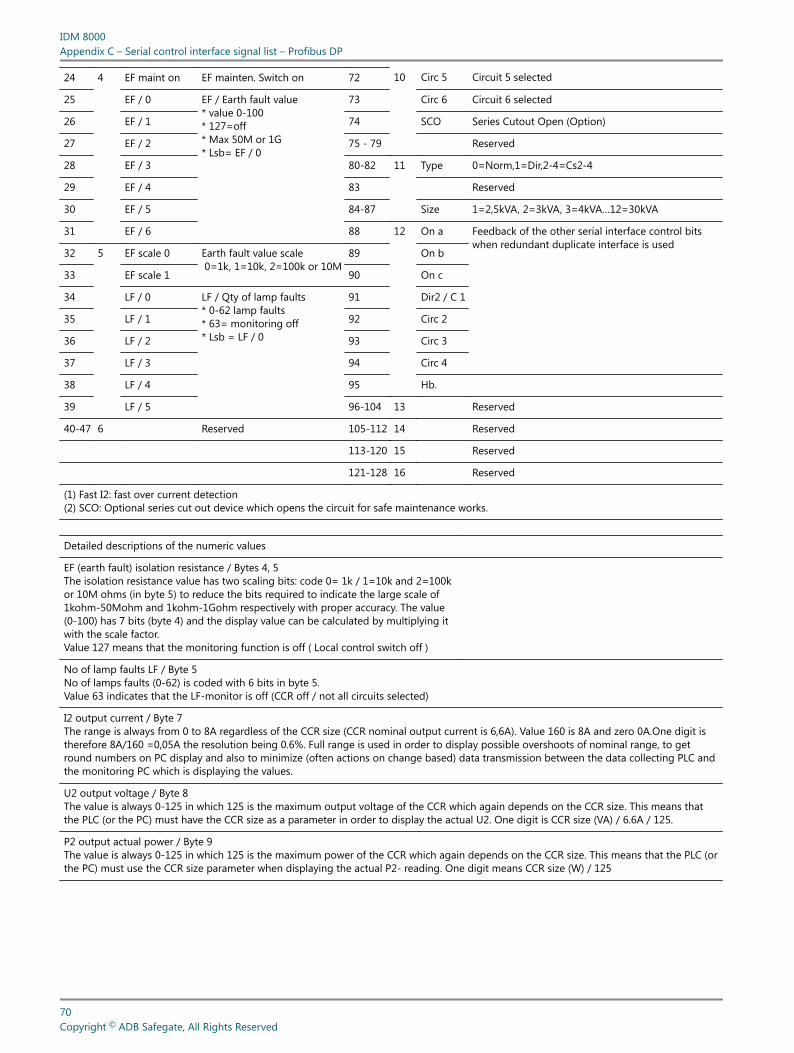
24 4 EF maint on EF mainten. Switch on 72 10 Circ 5 Circuit 5 selected
25 EF / 0 EF / Earth fault value* value 0-100* 127=off* Max 50M or 1G* Lsb= EF / 0
73 Circ 6 Circuit 6 selected
26 EF / 1 74 SCO Series Cutout Open (Option)
27 EF / 2 75 - 79 Reserved
28 EF / 3 80-82 11 Type 0=Norm,1=Dir,2-4=Cs2-4
29 EF / 4 83 Reserved
30 EF / 5 84-87 Size 1=2,5kVA, 2=3kVA, 3=4kVA…12=30kVA
31 EF / 6 88 12 On a Feedback of the other serial interface control bitswhen redundant duplicate interface is used
32 5 EF scale 0 Earth fault value scale 0=1k, 1=10k, 2=100k or 10M
89 On b
33 EF scale 1 90 On c
34 LF / 0 LF / Qty of lamp faults* 0-62 lamp faults* 63= monitoring off* Lsb = LF / 0
91 Dir2 / C 1
35 LF / 1 92 Circ 2
36 LF / 2 93 Circ 3
37 LF / 3 94 Circ 4
38 LF / 4 95 Hb.
39 LF / 5 96-104 13 Reserved
40-47 6 Reserved 105-112 14 Reserved
113-120 15 Reserved
121-128 16 Reserved
(1) Fast I2: fast over current detection(2) SCO: Optional series cut out device which opens the circuit for safe maintenance works.
Detailed descriptions of the numeric values
EF (earth fault) isolation resistance / Bytes 4, 5The isolation resistance value has two scaling bits: code 0= 1k / 1=10k and 2=100kor 10M ohms (in byte 5) to reduce the bits required to indicate the large scale of1kohm-50Mohm and 1kohm-1Gohm respectively with proper accuracy. The value(0-100) has 7 bits (byte 4) and the display value can be calculated by multiplying itwith the scale factor.Value 127 means that the monitoring function is off ( Local control switch off )
No of lamp faults LF / Byte 5No of lamps faults (0-62) is coded with 6 bits in byte 5.Value 63 indicates that the LF-monitor is off (CCR off / not all circuits selected)
I2 output current / Byte 7The range is always from 0 to 8A regardless of the CCR size (CCR nominal output current is 6,6A). Value 160 is 8A and zero 0A.One digit istherefore 8A/160 =0,05A the resolution being 0.6%. Full range is used in order to display possible overshoots of nominal range, to getround numbers on PC display and also to minimize (often actions on change based) data transmission between the data collecting PLC andthe monitoring PC which is displaying the values.
U2 output voltage / Byte 8The value is always 0-125 in which 125 is the maximum output voltage of the CCR which again depends on the CCR size. This means thatthe PLC (or the PC) must have the CCR size as a parameter in order to display the actual U2. One digit is CCR size (VA) / 6.6A / 125.
P2 output actual power / Byte 9The value is always 0-125 in which 125 is the maximum power of the CCR which again depends on the CCR size. This means that the PLC (orthe PC) must use the CCR size parameter when displaying the actual P2- reading. One digit means CCR size (W) / 125
IDM 8000Appendix C – Serial control interface signal list – Profibus DP
70Copyright © ADB Safegate, All Rights Reserved
CCR type and size parameters / Byte 11This byte indicates the CCRs type and size to control system and can be used to automatically update these parameters in the controlsystem.Three first bits (80-82, Lsb=80) define the CCR type in binary coded format: 0=normal CCR, 1=direction changer, 2-4= 2-4 circuit selectors(Dec values)Four last bits (84-87, Lsb=84) define the CCR size in binary coded format: 1=2,5kVA, 2=3kVA, 3=4kVA, 4=5kVA, 5=7,5kVA, 6=10kVA,7=12,5kVA, 8=15kVA, 9=17,5kVA, 10=20kVA, 11=25kVA and 12=30kVA (Dec values).
Redundant duplicated interface / other interface control bit status / Byte 12This information is provided for the control system to facilitate control channel / interface monitoring.
Displays which can be calculated from the above values in the control system- S2 = I2 * U2 = Apparent power taken by the load-Pf2 = P2 / S2 = load power factor, how inductive the load is ( lamp faults etc)
UM_IDM-8000, Rev. 1.7, 2021/05/06 71Copyright © ADB Safegate, All Rights Reserved

IDM 8000Appendix C – Serial control interface signal list – Profibus DP
72Copyright © ADB Safegate, All Rights Reserved
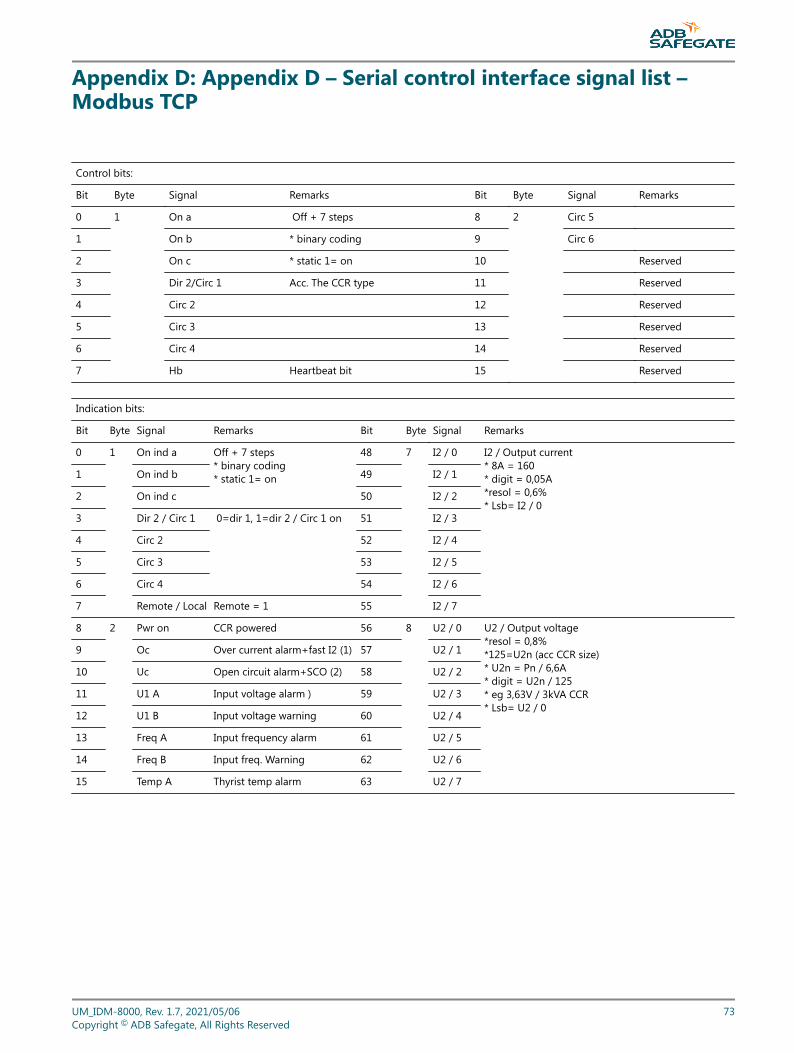
Appendix D: Appendix D – Serial control interface signal list –Modbus TCP
Control bits:
Bit Byte Signal Remarks Bit Byte Signal Remarks
0 1 On a Off + 7 steps 8 2 Circ 5
1 On b * binary coding 9 Circ 6
2 On c * static 1= on 10 Reserved
3 Dir 2/Circ 1 Acc. The CCR type 11 Reserved
4 Circ 2 12 Reserved
5 Circ 3 13 Reserved
6 Circ 4 14 Reserved
7 Hb Heartbeat bit 15 Reserved
Indication bits:
Bit Byte Signal Remarks Bit Byte Signal Remarks
0 1 On ind a Off + 7 steps* binary coding* static 1= on
48 7 I2 / 0 I2 / Output current* 8A = 160* digit = 0,05A*resol = 0,6%* Lsb= I2 / 0
1 On ind b 49 I2 / 1
2 On ind c 50 I2 / 2
3 Dir 2 / Circ 1 0=dir 1, 1=dir 2 / Circ 1 on 51 I2 / 3
4 Circ 2 52 I2 / 4
5 Circ 3 53 I2 / 5
6 Circ 4 54 I2 / 6
7 Remote / Local Remote = 1 55 I2 / 7
8 2 Pwr on CCR powered 56 8 U2 / 0 U2 / Output voltage*resol = 0,8%*125=U2n (acc CCR size)* U2n = Pn / 6,6A* digit = U2n / 125* eg 3,63V / 3kVA CCR* Lsb= U2 / 0
9 Oc Over current alarm+fast I2 (1) 57 U2 / 1
10 Uc Open circuit alarm+SCO (2) 58 U2 / 2
11 U1 A Input voltage alarm ) 59 U2 / 3
12 U1 B Input voltage warning 60 U2 / 4
13 Freq A Input frequency alarm 61 U2 / 5
14 Freq B Input freq. Warning 62 U2 / 6
15 Temp A Thyrist temp alarm 63 U2 / 7
UM_IDM-8000, Rev. 1.7, 2021/05/06 73Copyright © ADB Safegate, All Rights Reserved
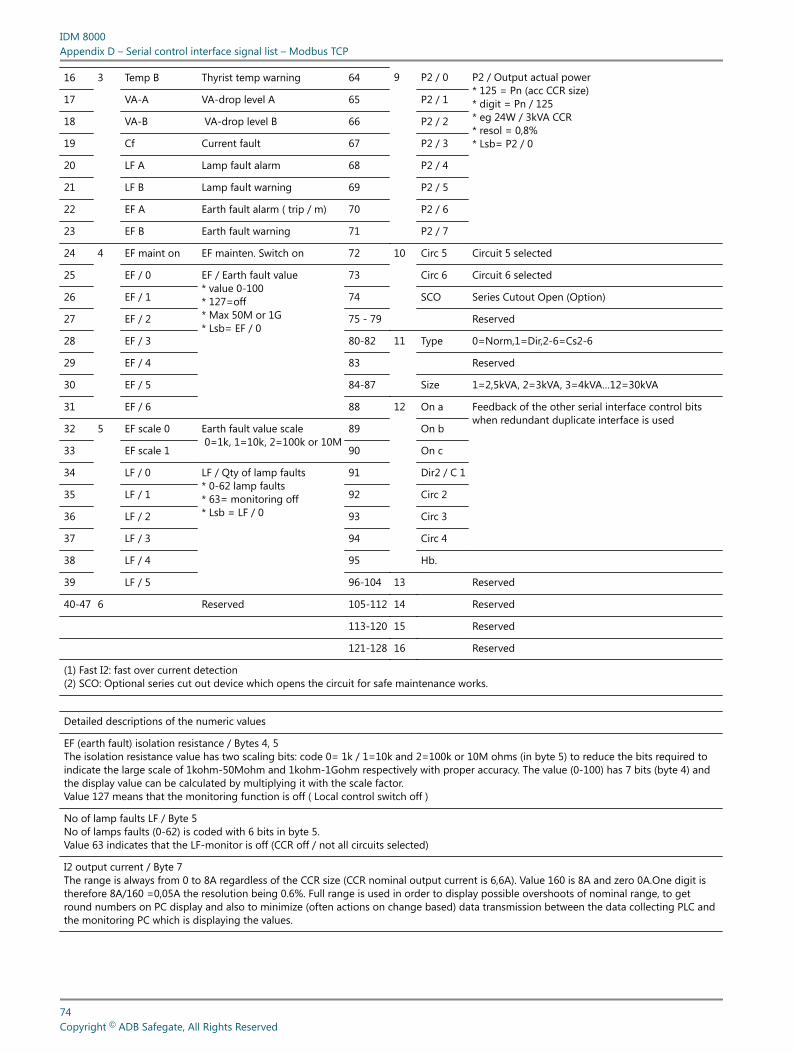
16 3 Temp B Thyrist temp warning 64 9 P2 / 0 P2 / Output actual power* 125 = Pn (acc CCR size)* digit = Pn / 125* eg 24W / 3kVA CCR* resol = 0,8%* Lsb= P2 / 0
17 VA-A VA-drop level A 65 P2 / 1
18 VA-B VA-drop level B 66 P2 / 2
19 Cf Current fault 67 P2 / 3
20 LF A Lamp fault alarm 68 P2 / 4
21 LF B Lamp fault warning 69 P2 / 5
22 EF A Earth fault alarm ( trip / m) 70 P2 / 6
23 EF B Earth fault warning 71 P2 / 7
24 4 EF maint on EF mainten. Switch on 72 10 Circ 5 Circuit 5 selected
25 EF / 0 EF / Earth fault value* value 0-100* 127=off* Max 50M or 1G* Lsb= EF / 0
73 Circ 6 Circuit 6 selected
26 EF / 1 74 SCO Series Cutout Open (Option)
27 EF / 2 75 - 79 Reserved
28 EF / 3 80-82 11 Type 0=Norm,1=Dir,2-6=Cs2-6
29 EF / 4 83 Reserved
30 EF / 5 84-87 Size 1=2,5kVA, 2=3kVA, 3=4kVA…12=30kVA
31 EF / 6 88 12 On a Feedback of the other serial interface control bitswhen redundant duplicate interface is used
32 5 EF scale 0 Earth fault value scale 0=1k, 1=10k, 2=100k or 10M
89 On b
33 EF scale 1 90 On c
34 LF / 0 LF / Qty of lamp faults* 0-62 lamp faults* 63= monitoring off* Lsb = LF / 0
91 Dir2 / C 1
35 LF / 1 92 Circ 2
36 LF / 2 93 Circ 3
37 LF / 3 94 Circ 4
38 LF / 4 95 Hb.
39 LF / 5 96-104 13 Reserved
40-47 6 Reserved 105-112 14 Reserved
113-120 15 Reserved
121-128 16 Reserved
(1) Fast I2: fast over current detection(2) SCO: Optional series cut out device which opens the circuit for safe maintenance works.
Detailed descriptions of the numeric values
EF (earth fault) isolation resistance / Bytes 4, 5The isolation resistance value has two scaling bits: code 0= 1k / 1=10k and 2=100k or 10M ohms (in byte 5) to reduce the bits required toindicate the large scale of 1kohm-50Mohm and 1kohm-1Gohm respectively with proper accuracy. The value (0-100) has 7 bits (byte 4) andthe display value can be calculated by multiplying it with the scale factor.Value 127 means that the monitoring function is off ( Local control switch off )
No of lamp faults LF / Byte 5No of lamps faults (0-62) is coded with 6 bits in byte 5.Value 63 indicates that the LF-monitor is off (CCR off / not all circuits selected)
I2 output current / Byte 7The range is always from 0 to 8A regardless of the CCR size (CCR nominal output current is 6,6A). Value 160 is 8A and zero 0A.One digit istherefore 8A/160 =0,05A the resolution being 0.6%. Full range is used in order to display possible overshoots of nominal range, to getround numbers on PC display and also to minimize (often actions on change based) data transmission between the data collecting PLC andthe monitoring PC which is displaying the values.
IDM 8000Appendix D – Serial control interface signal list – Modbus TCP
74Copyright © ADB Safegate, All Rights Reserved
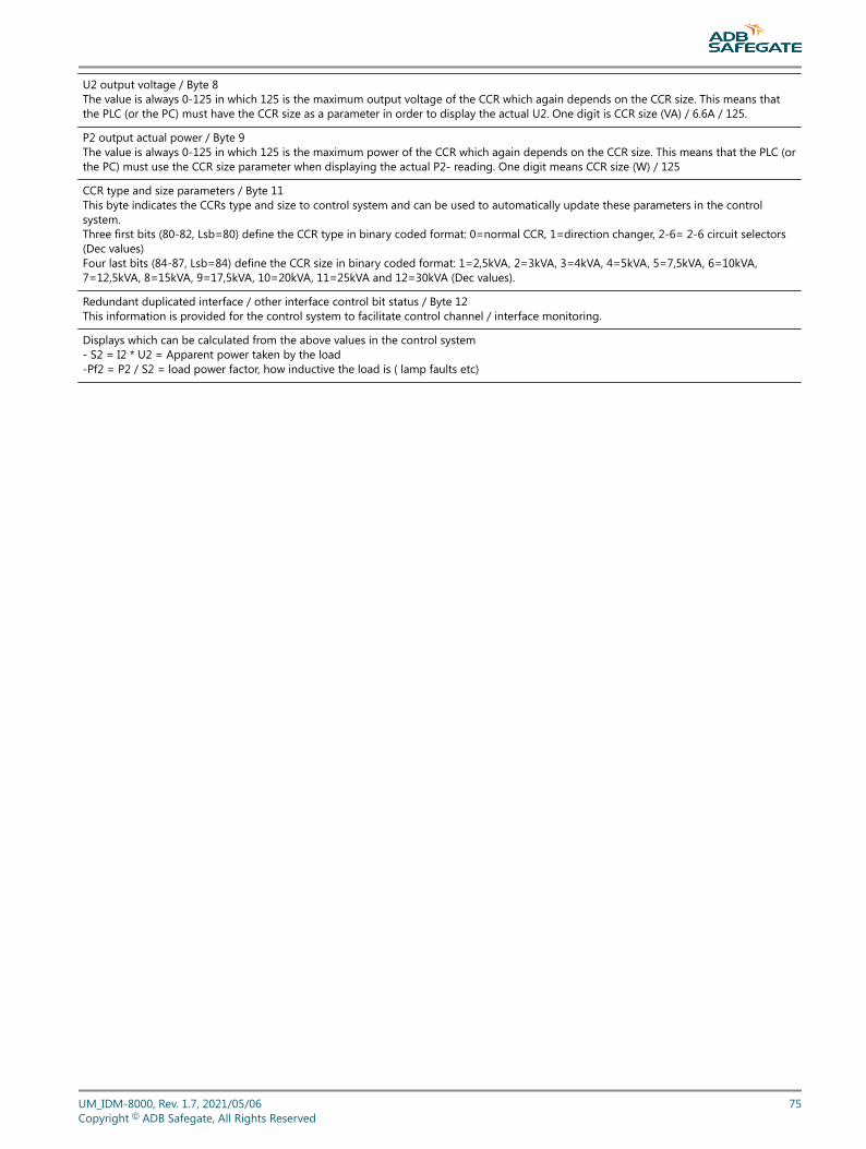
U2 output voltage / Byte 8The value is always 0-125 in which 125 is the maximum output voltage of the CCR which again depends on the CCR size. This means thatthe PLC (or the PC) must have the CCR size as a parameter in order to display the actual U2. One digit is CCR size (VA) / 6.6A / 125.
P2 output actual power / Byte 9The value is always 0-125 in which 125 is the maximum power of the CCR which again depends on the CCR size. This means that the PLC (orthe PC) must use the CCR size parameter when displaying the actual P2- reading. One digit means CCR size (W) / 125
CCR type and size parameters / Byte 11This byte indicates the CCRs type and size to control system and can be used to automatically update these parameters in the controlsystem.Three first bits (80-82, Lsb=80) define the CCR type in binary coded format: 0=normal CCR, 1=direction changer, 2-6= 2-6 circuit selectors(Dec values)Four last bits (84-87, Lsb=84) define the CCR size in binary coded format: 1=2,5kVA, 2=3kVA, 3=4kVA, 4=5kVA, 5=7,5kVA, 6=10kVA,7=12,5kVA, 8=15kVA, 9=17,5kVA, 10=20kVA, 11=25kVA and 12=30kVA (Dec values).
Redundant duplicated interface / other interface control bit status / Byte 12This information is provided for the control system to facilitate control channel / interface monitoring.
Displays which can be calculated from the above values in the control system- S2 = I2 * U2 = Apparent power taken by the load-Pf2 = P2 / S2 = load power factor, how inductive the load is ( lamp faults etc)
UM_IDM-8000, Rev. 1.7, 2021/05/06 75Copyright © ADB Safegate, All Rights Reserved

IDM 8000Appendix D – Serial control interface signal list – Modbus TCP
76Copyright © ADB Safegate, All Rights Reserved
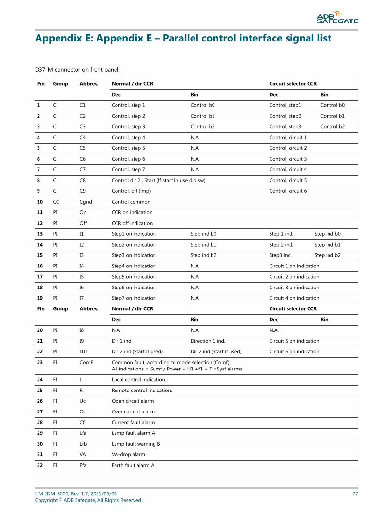
Appendix E: Appendix E – Parallel control interface signal list
D37-M connector on front panel:
Pin Group Abbrev. Normal / dir CCR Circuit selector CCR
Dec Bin Dec Bin
1 C C1 Control, step 1 Control b0 Control, step1 Control b0
2 C C2 Control, step 2 Control b1 Control, step2 Control b1
3 C C3 Control, step 3 Control b2 Control, step3 Control b2
4 C C4 Control, step 4 N.A Control, circuit 1
5 C C5 Control, step 5 N.A Control, circuit 2
6 C C6 Control, step 6 N.A Control, circuit 3
7 C C7 Control, step 7 N.A Control, circuit 4
8 C C8 Control dir 2 , Start (If start in use dip sw) Control, circuit 5
9 C C9 Control, off (imp) Control, circuit 6
10 CC Cgnd Control common
11 PI On CCR on indication
12 PI Off CCR off indication
13 PI I1 Step1 on indication Step ind b0 Step 1 ind. Step ind b0
14 PI I2 Step2 on indication Step ind b1 Step 2 ind. Step ind b1
15 PI I3 Step3 on indication Step ind b2 Step3 ind. Step ind b2
16 PI I4 Step4 on indication N.A Circuit 1 on indication.
17 PI I5 Step5 on indication N.A Circuit 2 on indication
18 PI I6 Step6 on indication N.A Circuit 3 on indication
19 PI I7 Step7 on indication N.A Circuit 4 on indication
Pin Group Abbrev. Normal / dir CCR Circuit selector CCR
Dec Bin Dec Bin
20 PI I8 N.A N.A N.A.
21 PI I9 Dir 1 ind. Direction 1 ind. Circuit 5 on indication
22 PI I10 Dir 2 ind.(Start if used) Dir 2 ind.(Start if used) Circuit 6 on indication
23 FI ComF Common fault, according to mode selection (Comf):All indications = Sumf / Power + U1 +f1 + T =Sysf alarms
24 FI L Local control indication.
25 FI R Remote control indication.
26 FI Uc Open circuit alarm
27 FI Oc Over current alarm
28 FI Cf Current fault alarm
29 FI Lfa Lamp fault alarm A
30 FI Lfb Lamp fault warning B
31 FI VA VA-drop alarm
32 FI Efa Earth fault alarm A
UM_IDM-8000, Rev. 1.7, 2021/05/06 77Copyright © ADB Safegate, All Rights Reserved
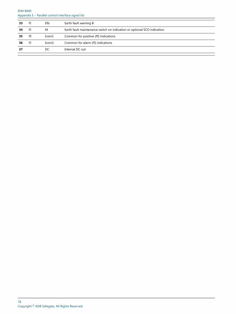
33 FI Efb Earth fault warning B
34 FI M Earth fault maintenance switch on indication or optional SCO indication.
35 PI Icom1 Common for positive (PI) indications
36 FI Icom2 Common for alarm (FI) indications
37 DC Internal DC out
IDM 8000Appendix E – Parallel control interface signal list
78Copyright © ADB Safegate, All Rights Reserved
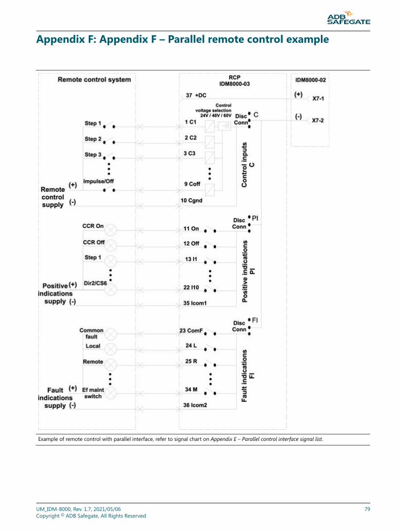
Appendix F: Appendix F – Parallel remote control example
Example of remote control with parallel interface, refer to signal chart on Appendix E – Parallel control interface signal list.
UM_IDM-8000, Rev. 1.7, 2021/05/06 79Copyright © ADB Safegate, All Rights Reserved

IDM 8000Appendix F – Parallel remote control example
80Copyright © ADB Safegate, All Rights Reserved
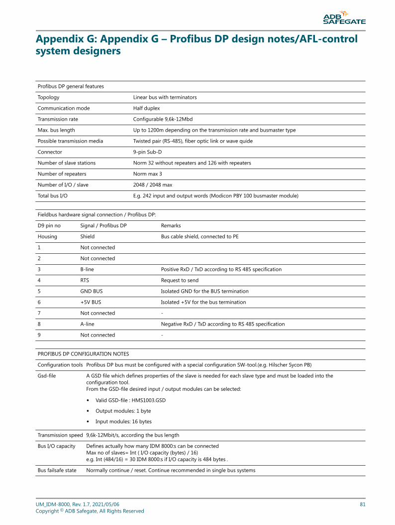
Appendix G: Appendix G – Profibus DP design notes/AFL-controlsystem designers
Profibus DP general features
Topology Linear bus with terminators
Communication mode Half duplex
Transmission rate Configurable 9,6k-12Mbd
Max. bus length Up to 1200m depending on the transmission rate and busmaster type
Possible transmission media Twisted pair (RS-485), fiber optic link or wave quide
Connector 9-pin Sub-D
Number of slave stations Norm 32 without repeaters and 126 with repeaters
Number of repeaters Norm max 3
Number of I/O / slave 2048 / 2048 max
Total bus I/O E.g. 242 input and output words (Modicon PBY 100 busmaster module)
Fieldbus hardware signal connection / Profibus DP:
D9 pin no Signal / Profibus DP Remarks
Housing Shield Bus cable shield, connected to PE
1 Not connected
2 Not connected
3 B-line Positive RxD / TxD according to RS 485 specification
4 RTS Request to send
5 GND BUS Isolated GND for the BUS termination
6 +5V BUS Isolated +5V for the bus termination
7 Not connected -
8 A-line Negative RxD / TxD according to RS 485 specification
9 Not connected -
PROFIBUS DP CONFIGURATION NOTES
Configuration tools Profibus DP bus must be configured with a special configuration SW-tool.(e.g. Hilscher Sycon PB)
Gsd-file A GSD file which defines properties of the slave is needed for each slave type and must be loaded into theconfiguration tool.From the GSD-file desired input / output modules can be selected:
• Valid GSD-file : HMS1003.GSD
• Output modules: 1 byte
• Input modules: 16 bytes
Transmission speed 9,6k-12Mbit/s, according the bus length
Bus I/O capacity Defines actually how many IDM 8000:s can be connectedMax no of slaves= Int ( I/O capacity (bytes) / 16)e.g. Int (484/16) = 30 IDM 8000:s if I/O capacity is 484 bytes .
Bus failsafe state Normally continue / reset. Continue recommended in single bus systems
UM_IDM-8000, Rev. 1.7, 2021/05/06 81Copyright © ADB Safegate, All Rights Reserved

Failsafe mode / Use of the heartbeat bit recommended
The CCR is considered to be online if the Profibus DP protocol is running but cannot know if the connection to host computer actuallyexists. (It is possible that the Profibus DP busmaster is running without connection to the host computer).The failsafe Hb (heartbeat bit) function can be used to check the host computer connection: Hb bit changes it state in max 1s intervals (thisfunctionality must be included in the control system) which the CCR checks to define its online status.
IDM 8000Appendix G – Profibus DP design notes/AFL-control system designers
82Copyright © ADB Safegate, All Rights Reserved
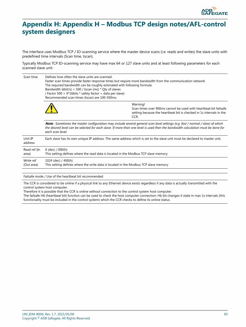
Appendix H: Appendix H – Modbus TCP design notes/AFL-controlsystem designers
The interface uses Modbus TCP / IO-scanning service where the master device scans (i.e. reads and writes) the slave units withpredefined time intervals (Scan time, tscan).
Typically Modbus TCP IO-scanning service may have max 64 or 127 slave units and at least following parameters for eachscanned slave unit:
Scan time Defines how often the slave units are scanned.Faster scan times provide faster response times but require more bandwidth from the communication networkThe required bandwidth can be roughly estimated with following formula:Bandwidth (kbit/s) = 500 / tscan (ms) * Qty of slaves( Factor 500 = 9*16bits * safety factor = data per slave)Recommended scan times (tscan) are 100-500ms.
Warning!Scan times over 900ms cannot be used with heartbeat bit failsafesetting because the heartbeat bit is checked in 1s intervals in theCCR.
Note : Sometimes the master configuration may include several general scan level settings (e.g. fast / normal / slow) of whichthe desired level can be selected for each slave. If more than one level is used then the bandwidth calculation must be done foreach scan level.
Unit IPaddress
Each slave has its own unique IP address. The same address which is set to the slave unit must be declared to master unit.
Read ref (Inarea)
0 (dec) / 000(h)This setting defines where the read data is located in the Modbus TCP slave memory
Write ref(Out area)
1024 (dec) / 400(h)This setting defines where the write data is located in the Modbus TCP slave memory
Failsafe mode / Use of the heartbeat bit recommended
The CCR is considered to be online if a physical link to any Ethernet device exists regardless if any data is actually transmitted with thecontrol system host computer.Therefore it is possible that the CCR is online without connection to the control system host computer.The failsafe Hb (heartbeat bit) function can be used to check the host computer connection: Hb bit changes it state in max 1s intervals (thisfunctionality must be included in the control system) which the CCR checks to define its online status.
UM_IDM-8000, Rev. 1.7, 2021/05/06 83Copyright © ADB Safegate, All Rights Reserved

IDM 8000Appendix H – Modbus TCP design notes/AFL-control system designers
84Copyright © ADB Safegate, All Rights Reserved
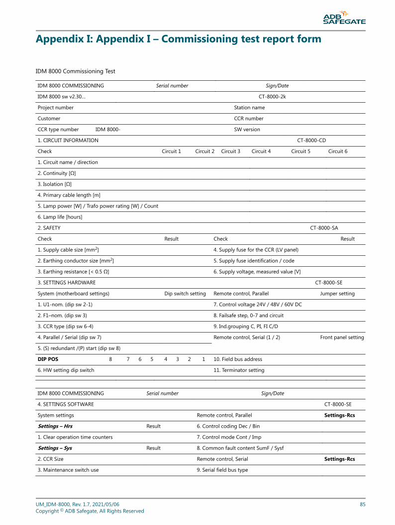
Appendix I: Appendix I – Commissioning test report form
IDM 8000 Commissioning Test
IDM 8000 COMMISSIONING Serial number Sign/Date
IDM 8000 sw v2.30… CT-8000-2k
Project number Station name
Customer CCR number
CCR type number IDM 8000- SW version
1. CIRCUIT INFORMATION CT-8000-CD
Check Circuit 1 Circuit 2 Circuit 3 Circuit 4 Circuit 5 Circuit 6
1. Circuit name / direction
2. Continuity [Ω]
3. Isolation [Ω]
4. Primary cable length [m]
5. Lamp power [W] / Trafo power rating [W] / Count
6. Lamp life [hours]
2. SAFETY CT-8000-SA
Check Result Check Result
1. Supply cable size [mm2] 4. Supply fuse for the CCR (LV panel)
2. Earthing conductor size [mm2] 5. Supply fuse identification / code
3. Earthing resistance [< 0.5 Ω] 6. Supply voltage, measured value [V]
3. SETTINGS HARDWARE CT-8000-SE
System (motherboard settings) Dip switch setting Remote control, Parallel Jumper setting
1. U1-nom. (dip sw 2-1) 7. Control voltage 24V / 48V / 60V DC
2. F1–nom. (dip sw 3) 8. Failsafe step, 0-7 and circuit
3. CCR type (dip sw 6-4) 9. Ind.grouping C, PI, FI C/D
4. Parallel / Serial (dip sw 7) Remote control, Serial (1 / 2) Front panel setting
5. (S) redundant /(P) start (dip sw 8)
DIP POS 8 7 6 5 4 3 2 1 10. Field bus address
6. HW setting dip switch 11. Terminator setting
IDM 8000 COMMISSIONING Serial number Sign/Date
4. SETTINGS SOFTWARE CT-8000-SE
System settings Remote control, Parallel Settings-Rcs
Settings – Hrs Result 6. Control coding Dec / Bin
1. Clear operation time counters 7. Control mode Cont / Imp
Settings – Sys Result 8. Common fault content SumF / Sysf
2. CCR Size Remote control, Serial Settings-Rcs
3. Maintenance switch use 9. Serial field bus type
UM_IDM-8000, Rev. 1.7, 2021/05/06 85Copyright © ADB Safegate, All Rights Reserved
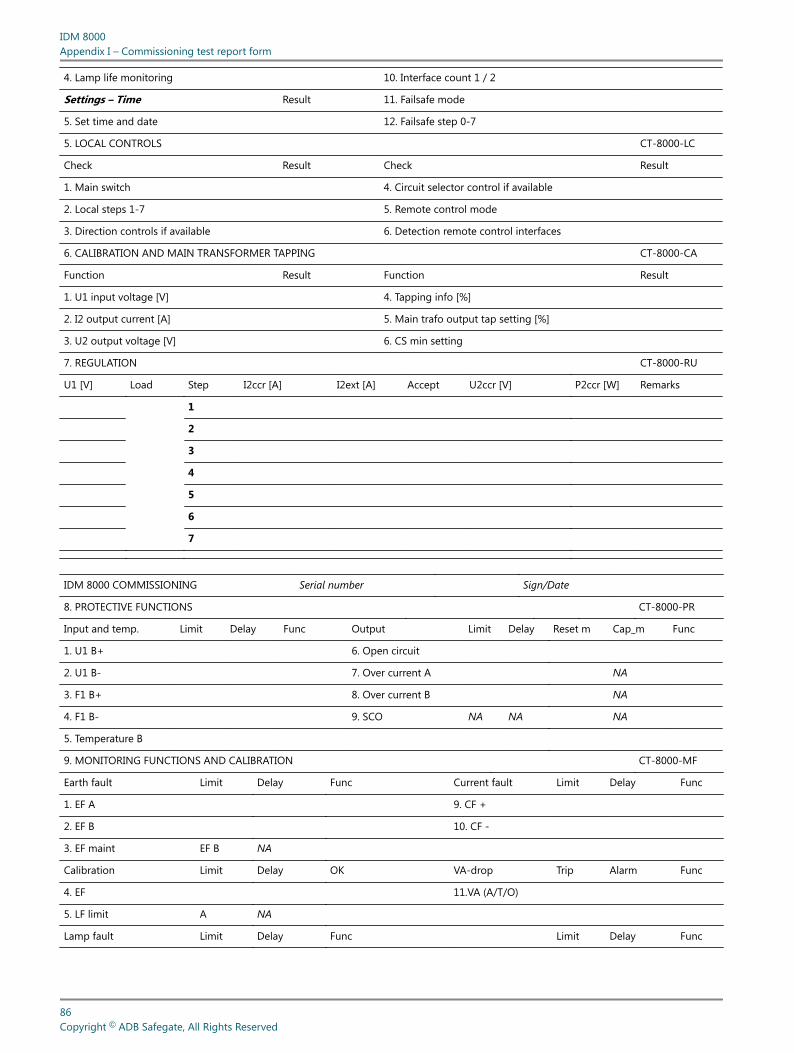
4. Lamp life monitoring 10. Interface count 1 / 2
Settings – Time Result 11. Failsafe mode
5. Set time and date 12. Failsafe step 0-7
5. LOCAL CONTROLS CT-8000-LC
Check Result Check Result
1. Main switch 4. Circuit selector control if available
2. Local steps 1-7 5. Remote control mode
3. Direction controls if available 6. Detection remote control interfaces
6. CALIBRATION AND MAIN TRANSFORMER TAPPING CT-8000-CA
Function Result Function Result
1. U1 input voltage [V] 4. Tapping info [%]
2. I2 output current [A] 5. Main trafo output tap setting [%]
3. U2 output voltage [V] 6. CS min setting
7. REGULATION CT-8000-RU
U1 [V] Load Step I2ccr [A] I2ext [A] Accept U2ccr [V] P2ccr [W] Remarks
1
2
3
4
5
6
7
IDM 8000 COMMISSIONING Serial number Sign/Date
8. PROTECTIVE FUNCTIONS CT-8000-PR
Input and temp. Limit Delay Func Output Limit Delay Reset m Cap_m Func
1. U1 B+ 6. Open circuit
2. U1 B- 7. Over current A NA
3. F1 B+ 8. Over current B NA
4. F1 B- 9. SCO NA NA NA
5. Temperature B
9. MONITORING FUNCTIONS AND CALIBRATION CT-8000-MF
Earth fault Limit Delay Func Current fault Limit Delay Func
1. EF A 9. CF +
2. EF B 10. CF -
3. EF maint EF B NA
Calibration Limit Delay OK VA-drop Trip Alarm Func
4. EF 11.VA (A/T/O)
5. LF limit A NA
Lamp fault Limit Delay Func Limit Delay Func
IDM 8000Appendix I – Commissioning test report form
86Copyright © ADB Safegate, All Rights Reserved
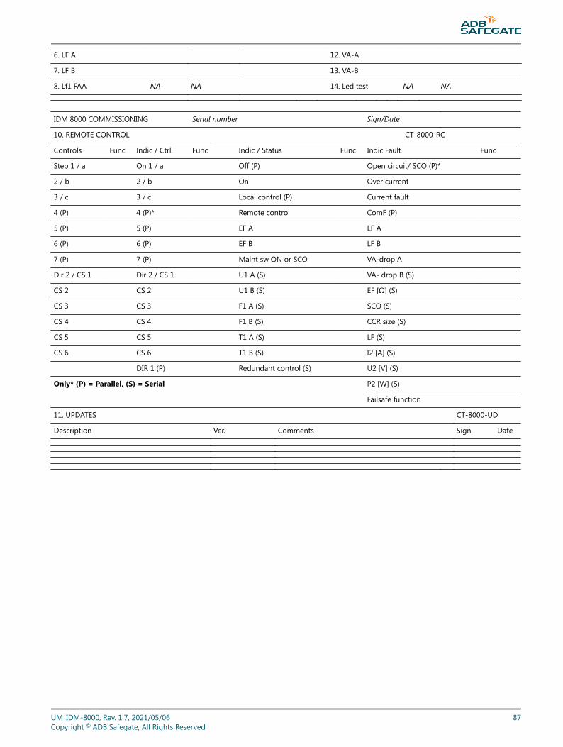
6. LF A 12. VA-A
7. LF B 13. VA-B
8. Lf1 FAA NA NA 14. Led test NA NA
IDM 8000 COMMISSIONING Serial number Sign/Date
10. REMOTE CONTROL CT-8000-RC
Controls Func Indic / Ctrl. Func Indic / Status Func Indic Fault Func
Step 1 / a On 1 / a Off (P) Open circuit/ SCO (P)*
2 / b 2 / b On Over current
3 / c 3 / c Local control (P) Current fault
4 (P) 4 (P)* Remote control ComF (P)
5 (P) 5 (P) EF A LF A
6 (P) 6 (P) EF B LF B
7 (P) 7 (P) Maint sw ON or SCO VA-drop A
Dir 2 / CS 1 Dir 2 / CS 1 U1 A (S) VA- drop B (S)
CS 2 CS 2 U1 B (S) EF [Ω] (S)
CS 3 CS 3 F1 A (S) SCO (S)
CS 4 CS 4 F1 B (S) CCR size (S)
CS 5 CS 5 T1 A (S) LF (S)
CS 6 CS 6 T1 B (S) I2 [A] (S)
DIR 1 (P) Redundant control (S) U2 [V] (S)
Only* (P) = Parallel, (S) = Serial P2 [W] (S)
Failsafe function
11. UPDATES CT-8000-UD
Description Ver. Comments Sign. Date
UM_IDM-8000, Rev. 1.7, 2021/05/06 87Copyright © ADB Safegate, All Rights Reserved

IDM 8000Appendix I – Commissioning test report form
88Copyright © ADB Safegate, All Rights Reserved
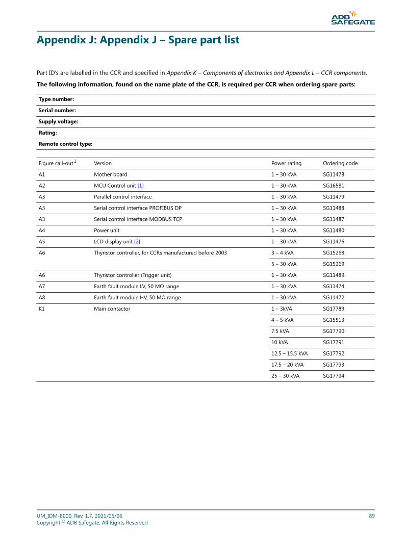
Appendix J: Appendix J – Spare part list
Part ID’s are labelled in the CCR and specified in Appendix K – Components of electronics and Appendix L – CCR components.
The following information, found on the name plate of the CCR, is required per CCR when ordering spare parts:
Type number:
Serial number:
Supply voltage:
Rating:
Remote control type:
Figure call-out 1 Version Power rating Ordering code
A1 Mother board 1 – 30 kVA SG11478
A2 MCU Control unit [1] 1 – 30 kVA SG16581
A3 Parallel control interface 1 – 30 kVA SG11479
A3 Serial control interface PROFIBUS DP 1 – 30 kVA SG11488
A3 Serial control interface MODBUS TCP 1 – 30 kVA SG11487
A4 Power unit 1 – 30 kVA SG11480
A5 LCD display unit [2] 1 – 30 kVA SG11476
A6 Thyristor controller, for CCRs manufactured before 2003 3 – 4 kVA SG15268
5 – 30 kVA SG15269
A6 Thyristor controller (Trigger unit) 1 – 30 kVA SG11489
A7 Earth fault module LV, 50 MΩ range 1 – 30 kVA SG11474
A8 Earth fault module HV, 50 MΩ range 1 – 30 kVA SG11472
K1 Main contactor 1 – 3kVA SG17789
4 – 5 kVA SG15513
7.5 kVA SG17790
10 kVA SG17791
12.5 – 15.5 kVA SG17792
17.5 – 20 kVA SG17793
25 – 30 kVA SG17794
UM_IDM-8000, Rev. 1.7, 2021/05/06 89Copyright © ADB Safegate, All Rights Reserved
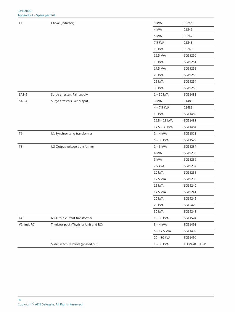
L1 Choke (Inductor) 3 kVA 19245
4 kVA 19246
5 kVA 19247
7.5 kVA 19248
10 kVA 19249
12.5 kVA SG19250
15 kVA SG19251
17.5 kVA SG19252
20 kVA SG19253
25 kVA SG19254
30 kVA SG19255
SA1-2 Surge arresters Pair supply 1 – 30 kVA SG11481
SA3-4 Surge arresters Pair output 3 kVA 11485
4 – 7.5 kVA 11486
10 kVA SG11482
12.5 – 15 kVA SG11483
17.5 – 30 kVA SG11484
T2 U1 Synchronizing transformer 1 – 4 kVA SG11521
5 – 30 kVA SG11522
T3 U2 Output voltage transformer 1 – 3 kVA SG19234
4 kVA SG19235
5 kVA SG19236
7.5 kVA SG19237
10 kVA SG19238
12.5 kVA SG19239
15 kVA SG19240
17.5 kVA SG19241
20 kVA SG19242
25 kVA SG15429
30 kVA SG19243
T4 I2 Output current transformer 1 – 30 kVA SG11524
V1 (incl. RC) Thyristor pack (Thyristor Unit and RC) 3 – 4 kVA SG11491
5 – 17.5 kVA SG11492
20 – 30 kVA SG11490
Slide Switch Terminal (phased out) 1 – 30 kVA ELLM6/8.STISPP
IDM 8000Appendix J – Spare part list
90Copyright © ADB Safegate, All Rights Reserved
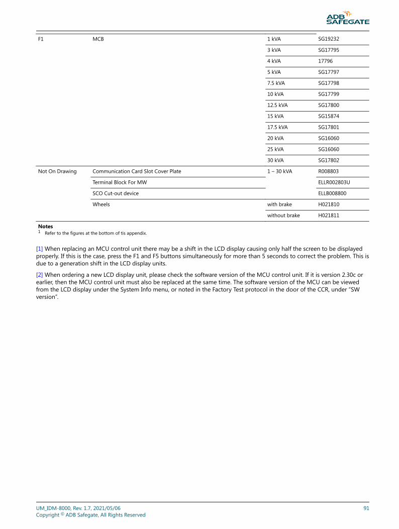
F1 MCB 1 kVA SG19232
3 kVA SG17795
4 kVA 17796
5 kVA SG17797
7.5 kVA SG17798
10 kVA SG17799
12.5 kVA SG17800
15 kVA SG15874
17.5 kVA SG17801
20 kVA SG16060
25 kVA SG16060
30 kVA SG17802
Not On Drawing Communication Card Slot Cover Plate 1 – 30 kVA R008803
Terminal Block For MW ELLR002803U
SCO Cut-out device ELLB008800
Wheels with brake H021810
without brake H021811
Notes1 Refer to the figures at the bottom of tis appendix.
[1] When replacing an MCU control unit there may be a shift in the LCD display causing only half the screen to be displayedproperly. If this is the case, press the F1 and F5 buttons simultaneously for more than 5 seconds to correct the problem. This isdue to a generation shift in the LCD display units.
[2] When ordering a new LCD display unit, please check the software version of the MCU control unit. If it is version 2.30c orearlier, then the MCU control unit must also be replaced at the same time. The software version of the MCU can be viewedfrom the LCD display under the System Info menu, or noted in the Factory Test protocol in the door of the CCR, under “SWversion”.
UM_IDM-8000, Rev. 1.7, 2021/05/06 91Copyright © ADB Safegate, All Rights Reserved
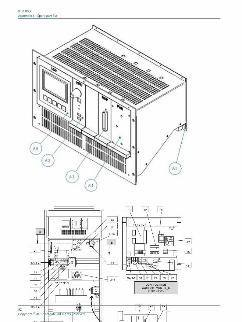
IDM 8000Appendix J – Spare part list
92Copyright © ADB Safegate, All Rights Reserved
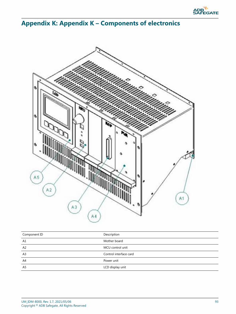
Appendix K: Appendix K – Components of electronics
Component ID Description
A1 Mother board
A2 MCU control unit
A3 Control interface card
A4 Power unit
A5 LCD display unit
UM_IDM-8000, Rev. 1.7, 2021/05/06 93Copyright © ADB Safegate, All Rights Reserved

IDM 8000Appendix K – Components of electronics
94Copyright © ADB Safegate, All Rights Reserved
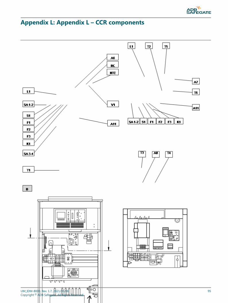
Appendix L: Appendix L – CCR components
Figure 12 – CCR components
Component ID Description Component ID Description
A6 Thyristor controller (Trigger unit) T1 Main Transformer
UM_IDM-8000, Rev. 1.7, 2021/05/06 95Copyright © ADB Safegate, All Rights Reserved
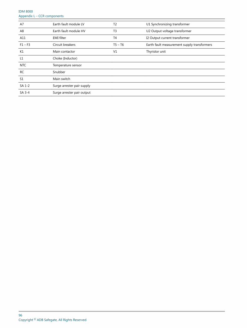
A7 Earth fault module LV T2 U1 Synchronizing transformer
A8 Earth fault module HV T3 U2 Output voltage transformer
A11 EMI filter T4 I2 Output current transformer
F1 – F3 Circuit breakers T5 – T6 Earth fault measurement supply transformers
K1 Main contactor V1 Thyristor unit
L1 Choke (Inductor)
NTC Temperature sensor
RC Snubber
S1 Main switch
SA 1-2 Surge arrester pair supply
SA 3-4 Surge arrester pair output
IDM 8000Appendix L – CCR components
96Copyright © ADB Safegate, All Rights Reserved
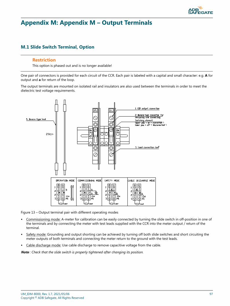
Appendix M: Appendix M – Output Terminals
M.1 Slide Switch Terminal, Option
RestrictionThis option is phased out and is no longer available!
One pair of connectors is provided for each circuit of the CCR. Each pair is labeled with a capital and small character: e.g. A foroutput and a for return of the loop.
The output terminals are mounted on isolated rail and insulators are also used between the terminals in order to meet thedielectric test voltage requirements.
Figure 13 – Output terminal pair with different operating modes
• Commissioning mode: A-meter for calibration can be easily connected by turning the slide switch in off-position in one ofthe terminals and by connecting the meter with test leads supplied with the CCR into the meter output / return of theterminal.
• Safety mode: Grounding and output shorting can be achieved by turning off both slide switches and short circuiting themeter outputs of both terminals and connecting the meter return to the ground with the test leads.
• Cable discharge mode: Use cable discharge to remove capacitive voltage from the cable.
Note : Check that the slide switch is properly tightened after changing its position.
UM_IDM-8000, Rev. 1.7, 2021/05/06 97Copyright © ADB Safegate, All Rights Reserved
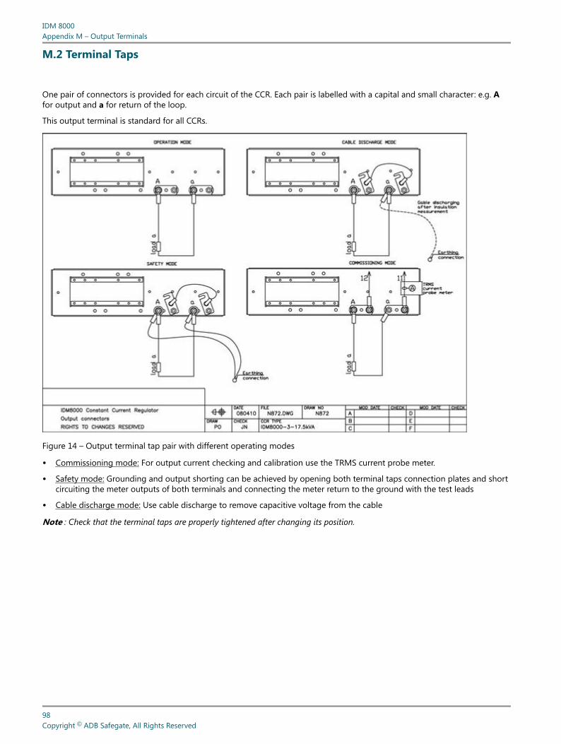
M.2 Terminal Taps
One pair of connectors is provided for each circuit of the CCR. Each pair is labelled with a capital and small character: e.g. Afor output and a for return of the loop.
This output terminal is standard for all CCRs.
Figure 14 – Output terminal tap pair with different operating modes
• Commissioning mode: For output current checking and calibration use the TRMS current probe meter.
• Safety mode: Grounding and output shorting can be achieved by opening both terminal taps connection plates and shortcircuiting the meter outputs of both terminals and connecting the meter return to the ground with the test leads
• Cable discharge mode: Use cable discharge to remove capacitive voltage from the cable
Note : Check that the terminal taps are properly tightened after changing its position.
IDM 8000Appendix M – Output Terminals
98Copyright © ADB Safegate, All Rights Reserved
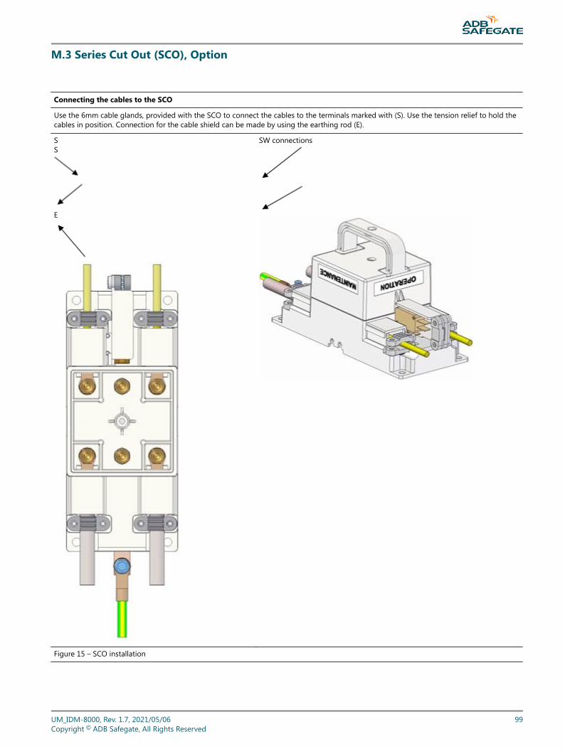
M.3 Series Cut Out (SCO), Option
Connecting the cables to the SCO
Use the 6mm cable glands, provided with the SCO to connect the cables to the terminals marked with (S). Use the tension relief to hold thecables in position. Connection for the cable shield can be made by using the earthing rod (E).
S S
E
SW connections
Figure 15 – SCO installation
UM_IDM-8000, Rev. 1.7, 2021/05/06 99Copyright © ADB Safegate, All Rights Reserved
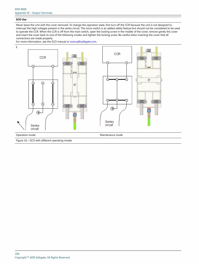
SCO Use
Never leave the unit with the cover removed. To change the operation state, first turn off the CCR because the unit is not designed tointerrupt the high voltages present in the series circuit. The micro switch is an added safety feature but should not be considered to be usedto operate the CCR. When the CCR is off from the main switch, open the locking screw in the middle of the cover, remove gently the coverand insert the cover back to one of the following modes and tighten the locking screw. Be careful when inserting the cover that allconnections are made properly.For more information, see the SCO manual or www.adbsafegate.com.
E
Operation mode Maintenance mode
Figure 16 – SCO with different operating modes
IDM 8000Appendix M – Output Terminals
100Copyright © ADB Safegate, All Rights Reserved

UM_IDM-8000, Rev. 1.7, 2021/05/06 101Copyright © ADB Safegate, All Rights Reserved

IDM 8000Appendix M – Output Terminals
102Copyright © ADB Safegate, All Rights Reserved

Appendix N: SUPPORT
Our experienced engineers are available for support and service at all times, 24 hour/7 days a week. They are part of adynamic organization making sure the entire ADB SAFEGATE is committed to minimal disturbance for airport operations.
ADB SAFEGATE Support
Live Technical Support - AmericasIf at any time you have a question or concern about your product, just contact ADB SAFEGATE’stechnical service department. Trained in all areas of system issues, troubleshooting, quality controland technical assistance, our highly experienced Technical support specialists are available 24 hoursa day, seven days a week to provide assistance over the phone.ADB SAFEGATE Americas Technical Service & Support (US & Canada): +1-800-545-4157ADB SAFEGATE Americas Technical Service & Support (International): +1-614-861-1304During regular business hours, you can also Chat with a Service Technician. We look forward toworking with you!Before You CallWhen you have an airfield lighting or system control system problem it is our goal to supportairfield maintenance staff as quickly as possible. To support this effort we ask that you have thefollowing information ready before calling.
• The airport code
• If not with an airport, then company name (prefer customer id number)
• Contact phone number and email address
• Product with part number preferable or product number
• Have you reviewed the product’s manual and troubleshooting guide
• Do you have a True RMS meter available (and any other necessary tools)
• Be located with the product ready to troubleshoot
NoteFor more information, see www.adbsafegate.com, or contact ADB SAFEGATE Support via email [email protected] orBrussels: +32 2 722 17 11Rest of Europe: +46 (0) 40 699 17 40Americas: +1 614 861 1304. Press 3 for technical service or press 4 for sales support.China: +86 (10) 8476 0106
N.1 ADB SAFEGATE Website
The ADB SAFEGATE website, www.adbsafegate.com, offers information regarding our airport solutions, products, company,news, links, downloads, references, contacts and more.
UM_IDM-8000, Rev. 1.7, 2021/05/06 103Copyright © ADB Safegate, All Rights Reserved
N.2 Recycling
N.2.1 Local Authority RecyclingThe disposal of ADB SAFEGATE products is to be made at an applicable collection point for the recycling of electrical andelectronic equipment. The correct disposal of equipment prevents any potential negative consequences for the environmentand human health, which could otherwise be caused by inappropriate waste handling. The recycling of materials helps toconserve natural resources. For more detailed information about recycling of products, contact your local authority city office.
N.2.2 ADB SAFEGATE RecyclingADB SAFEGATE is fully committed to environmentally-conscious manufacturing with strict monitoring of our own processes aswell as supplier components and sub-contractor operations. ADB SAFEGATE offers a recycling program for our products to allcustomers worldwide, whether or not the products were sold within the EU.
ADB SAFEGATE products and/or specific electrical and electronic component parts which are fully removed/separated fromany customer equipment and returned will be accepted for our recycling program.
All items returned must be clearly labeled as follows:
• For ROHS/WEEE Recycling
• Sender contact information (Name, Business Address, Phone number).
• Main Unit Serial Number.
ADB SAFEGATE will continue to monitor and update according for any future requirements for EU directives as and when EUmember states implement new regulations and or amendments. It is our aim to maintain our compliance plan and assist ourcustomers.
IDM 8000SUPPORT
104Copyright © ADB Safegate, All Rights Reserved
Company Addresses
ADB SAFEGATE ADB SAFEGATE, Belgium:Leuvensesteenweg 585,B-1930 ZaventemBelgium
Contact:Tel.: +32 2 722 17 11,Fax: +32 2 722 17 64
Email: [email protected]: www.adbsafegate.com
Americas LLC ADB SAFEGATE, Americas:977 Gahanna Parkway,Columbus, OH 43230USA
Contact:Tel.: +1 (614) 861 1304,Fax: +1 (614) 864 2069
Email: [email protected]: www.adbsafegate.com
ADB SAFEGATE Sweden AB ADB SAFEGATE, Sweden:Djurhagegatan 19SE-213 76 MalmöSweden
Contact:Tel.: +46 (0)40 699 17 00,Fax: +46 (0)40 699 17 30
Email: [email protected]: www.adbsafegate.com
ADB SAFEGATE Airfield Technologies Ltd. China ADB SAFEGATE, China:Unit 603, D Block,CAMIC International Convention Center,No 3, Hua Jia Di East road, ChaoYang district,Beijing 100102P.R. China
Contact:Tel.: +86 (10) 8476 0106,Fax: +86 (10) 8476 0090
Email: [email protected]: www.adbsafegate.com
ADB SAFEGATE Germany GmbH ADB SAFEGATE Germany GmbH, Mannheim:Konrad-Zuse-Ring 6,D-68163 MannheimGermany
Contact:Tel.: +49 (621) 87 55 76-0,Fax: +49 (621) 87 55 76-55
Email: [email protected]: www.adbsafegate.com
UM_IDM-8000, Rev. 1.7, 2021/05/06 105Copyright © ADB Safegate, All Rights Reserved