Embed Size (px)
Citation preview
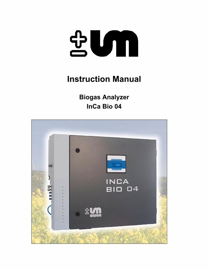
Instruction Manual
Biogas Analyzer InCa Bio 04
Instruction Manual InCa Bio 04 contents
___________________________________________________________________ 2 Manual InCa Bio 04 07-10-10 R2
- IMPORTANT -
Refer to the safety intructions before installation begins
Table of Contents Instruction Manual InCa Bio 04
___________________________________________________________________ Manual InCa Bio 04 07-10-10 R2 3
Table of contents
Table of contents .......................................................................................................... 3 1. Safety Instructions ....................................................................................... 4 2. Instrument Overview.................................................................................... 5 3. Technical Data............................................................................................. 6 3.1. Enclosure details ......................................................................................... 8 3.2. Installation requirements ........................................................................... 10 3.3. Mounting the instrument ............................................................................ 10 3.4. Gas connections........................................................................................ 11 3.4.1. Condensate pump ..................................................................................... 11 3.4.2. Air operated valve and jet pump connections ........................................... 12 3.5. Power supply ............................................................................................. 14 3.5.1. Electronic interface .................................................................................... 15 4. Calibration.................................................................................................. 17 4.1. Methane and Oxygen ................................................................................ 17 4.2. CO2 and H2S.............................................................................................. 17 5. Start Up...................................................................................................... 18 6. Menu Overview.......................................................................................... 19 6.1. Sub menus................................................................................................. 21 6.1.1. Measuring value memory .......................................................................... 21 6.1.2. Service password ...................................................................................... 21 6.1.2.1. Special measurement instantly ................................................................. 22 6.1.2.2. Number of measurement points ................................................................ 22 6.1.2.3. Measuring time per measuring point ......................................................... 23 6.1.2.4. Pause time per measurement point .......................................................... 23 6.1.2.5. Calibration.................................................................................................. 24 6.1.2.6. Auto calibration.......................................................................................... 24 6.1.2.7. Calibration.................................................................................................. 25 7. Status Codes ............................................................................................. 27 8. Maintenance and Service.......................................................................... 28 8.1. Pump life.................................................................................................... 28 8.2. Electro chemical sensor life....................................................................... 28 8.3. Optical sensor life ...................................................................................... 28 8.4. Condensate pump ..................................................................................... 28 8.5. Maintenance intervals................................................................................ 29 8.6. Software update ........................................................................................ 29 9. Spare Parts List ......................................................................................... 31
Instruction Manual InCa Bio 04 contents
___________________________________________________________________ 4 Manual InCa Bio 04 07-10-10 R2
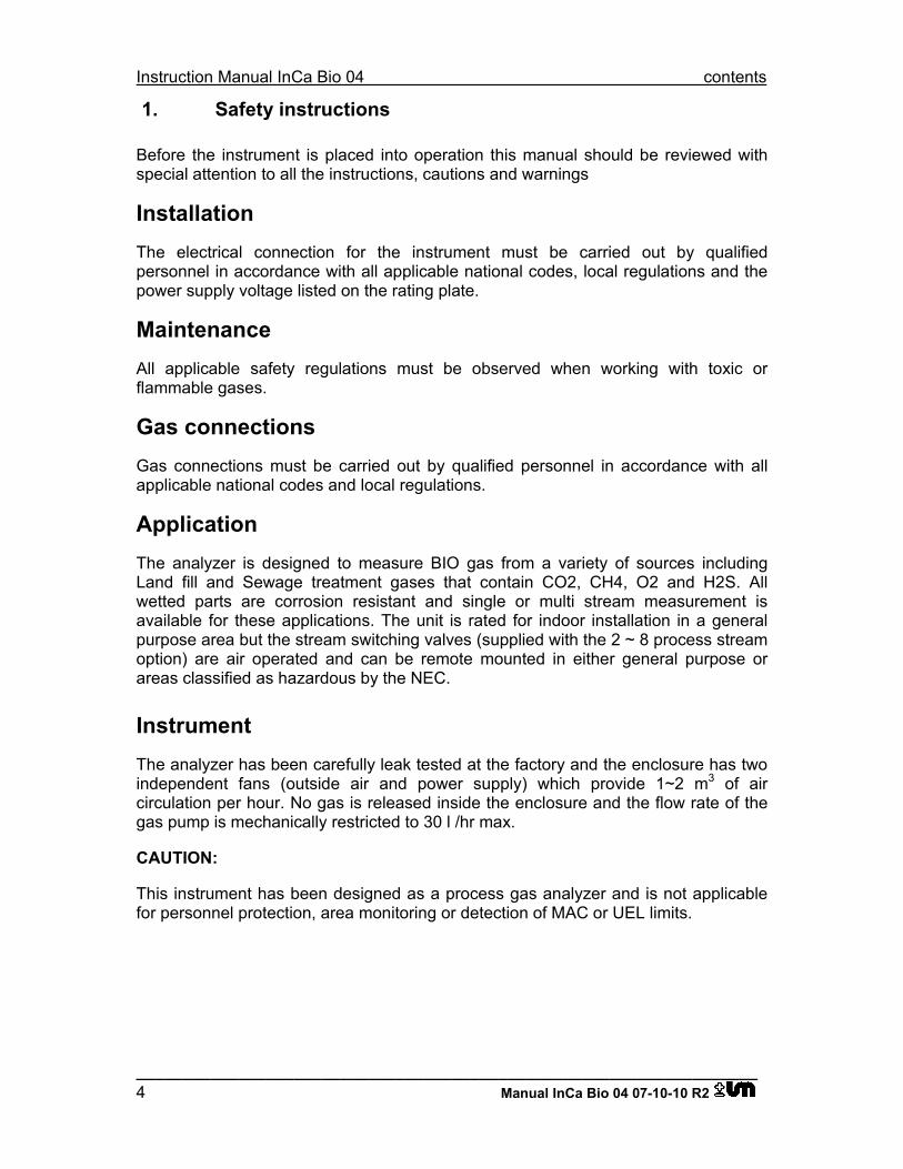
1. Safety instructions
Before the instrument is placed into operation this manual should be reviewed with special attention to all the instructions, cautions and warnings
Installation The electrical connection for the instrument must be carried out by qualified personnel in accordance with all applicable national codes, local regulations and the power supply voltage listed on the rating plate.
Maintenance All applicable safety regulations must be observed when working with toxic or flammable gases.
Gas connections Gas connections must be carried out by qualified personnel in accordance with all applicable national codes and local regulations.
Application The analyzer is designed to measure BIO gas from a variety of sources including Land fill and Sewage treatment gases that contain CO2, CH4, O2 and H2S. All wetted parts are corrosion resistant and single or multi stream measurement is available for these applications. The unit is rated for indoor installation in a general purpose area but the stream switching valves (supplied with the 2 ~ 8 process stream option) are air operated and can be remote mounted in either general purpose or areas classified as hazardous by the NEC.
Instrument The analyzer has been carefully leak tested at the factory and the enclosure has two independent fans (outside air and power supply) which provide 1~2 m3 of air circulation per hour. No gas is released inside the enclosure and the flow rate of the gas pump is mechanically restricted to 30 l /hr max.
CAUTION:
This instrument has been designed as a process gas analyzer and is not applicable for personnel protection, area monitoring or detection of MAC or UEL limits.
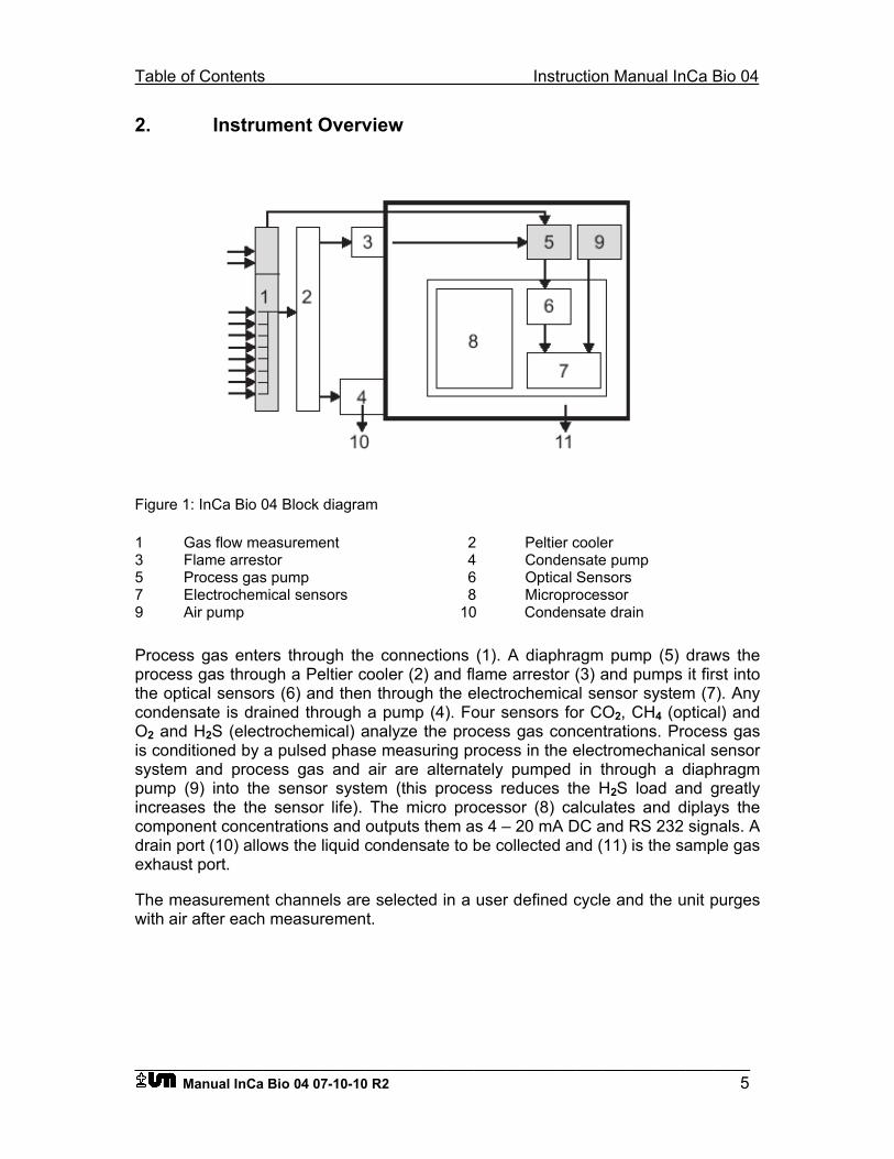
Table of Contents Instruction Manual InCa Bio 04
___________________________________________________________________ Manual InCa Bio 04 07-10-10 R2 5
2. Instrument Overview
Figure 1: InCa Bio 04 Block diagram
1 Gas flow measurement 2 Peltier cooler 3 Flame arrestor 4 Condensate pump 5 Process gas pump 6 Optical Sensors 7 Electrochemical sensors 8 Microprocessor 9 Air pump 10 Condensate drain
Process gas enters through the connections (1). A diaphragm pump (5) draws the process gas through a Peltier cooler (2) and flame arrestor (3) and pumps it first into the optical sensors (6) and then through the electrochemical sensor system (7). Any condensate is drained through a pump (4). Four sensors for CO2, CH4 (optical) and O2 and H2S (electrochemical) analyze the process gas concentrations. Process gas is conditioned by a pulsed phase measuring process in the electromechanical sensor system and process gas and air are alternately pumped in through a diaphragm pump (9) into the sensor system (this process reduces the H2S load and greatly increases the the sensor life). The micro processor (8) calculates and diplays the component concentrations and outputs them as 4 – 20 mA DC and RS 232 signals. A drain port (10) allows the liquid condensate to be collected and (11) is the sample gas exhaust port.
The measurement channels are selected in a user defined cycle and the unit purges with air after each measurement.
Instruction Manual InCa Bio 04 contents
___________________________________________________________________ 6 Manual InCa Bio 04 07-10-10 R2
3. Technical Data
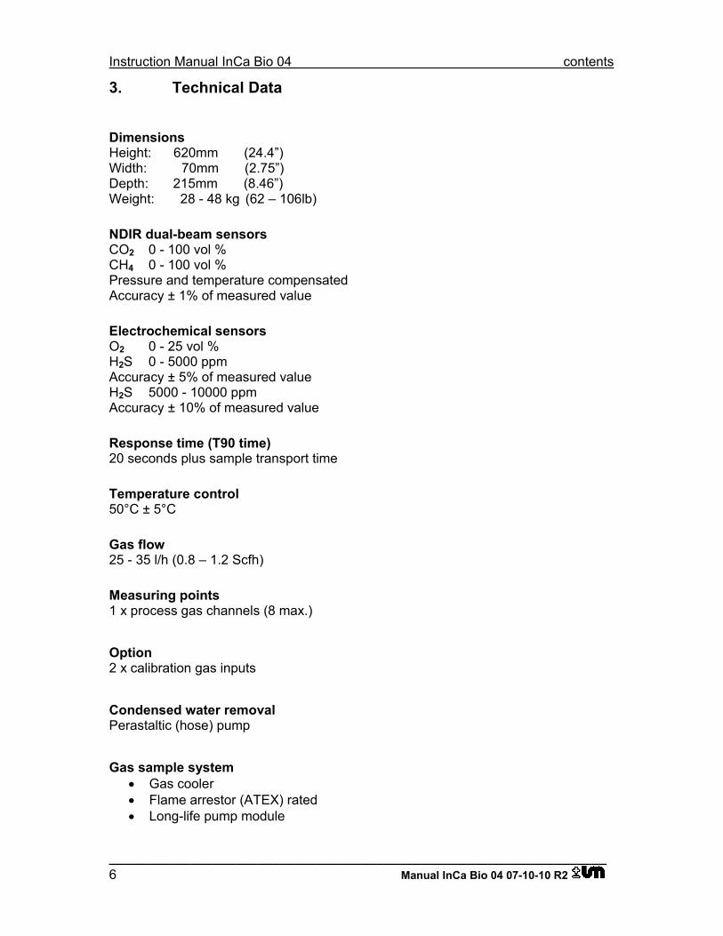
Dimensions Height: 620mm (24.4”) Width: 70mm (2.75”) Depth: 215mm (8.46”) Weight: 28 - 48 kg (62 – 106lb)
NDIR dual-beam sensors CO2 0 - 100 vol % CH4 0 - 100 vol % Pressure and temperature compensated Accuracy ± 1% of measured value
Electrochemical sensors O2 0 - 25 vol % H2S 0 - 5000 ppm Accuracy ± 5% of measured value H2S 5000 - 10000 ppm Accuracy ± 10% of measured value
Response time (T90 time) 20 seconds plus sample transport time
Temperature control 50°C ± 5°C
Gas flow 25 - 35 l/h (0.8 – 1.2 Scfh)
Measuring points 1 x process gas channels (8 max.)
Option 2 x calibration gas inputs
Condensed water removal Perastaltic (hose) pump
Gas sample system • Gas cooler • Flame arrestor (ATEX) rated • Long-life pump module
Table of Contents Instruction Manual InCa Bio 04
___________________________________________________________________ Manual InCa Bio 04 07-10-10 R2 7
Tube connections 6 mm OD 4 mm ID
Power supply 90 ~ 240 VAC, 50/60 Hz
Interfaces • 1 x RS 232 • 4 x 4 - 20 mA • 3 x Status relay
Operating temperature 5 - 45°C
Warm up time 15 minutes at 20°C
Instruction Manual InCa Bio 04 contents
___________________________________________________________________ 8 Manual InCa Bio 04 07-10-10 R2
3.1. Enclosure Details
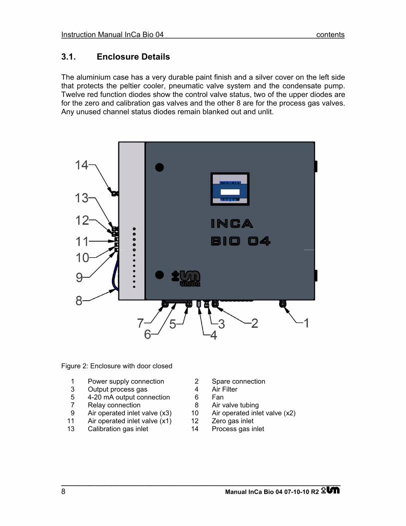
The aluminium case has a very durable paint finish and a silver cover on the left side that protects the peltier cooler, pneumatic valve system and the condensate pump. Twelve red function diodes show the control valve status, two of the upper diodes are for the zero and calibration gas valves and the other 8 are for the process gas valves. Any unused channel status diodes remain blanked out and unlit.
Figure 2: Enclosure with door closed
1 Power supply connection 2 Spare connection 3 Output process gas 4 Air Filter 5 4-20 mA output connection 6 Fan 7 Relay connection 8 Air valve tubing 9 Air operated inlet valve (x3) 10 Air operated inlet valve (x2) 11 Air operated inlet valve (x1) 12 Zero gas inlet 13 Calibration gas inlet 14 Process gas inlet
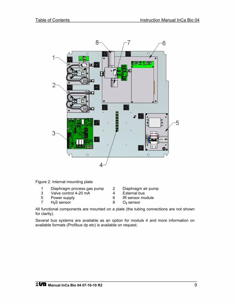
Table of Contents Instruction Manual InCa Bio 04
___________________________________________________________________ Manual InCa Bio 04 07-10-10 R2 9
Figure 2: Internal mounting plate
1 Diaphragm process gas pump 2 Diaphragm air pump 3 Valve control 4-20 mA 4 External bus 5 Power supply 6 IR sensor module 7 H2S sensor 8 O2 sensor
All functional components are mounted on a plate (the tubing connections are not shown for clarity). Several bus systems are available as an option for module 4 and more information on available formats (Profibus dp etc) is available on request.
Instruction Manual InCa Bio 04 contents
___________________________________________________________________ 10 Manual InCa Bio 04 07-10-10 R2
3.2. Installation requirements
The analyzer must be installed in a clean dry indoor general purpose area. The air controlled stream switching valves (supplied with the 2~8 process stream option) can be remote mounted in either general purpose or areas classified as hazardous by the NEC. The left side of the enclosure should be accessible for sample gas connections and the right-hand side only needs enough space to allow the door to open.
The ambient temperature has to be within the operating specification and the gas supply lines should also be above 0°C to avoid freezing conditions as the process gas is usually loaded with moisture.
3.3. Mounting the instrument
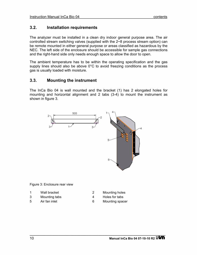
The InCa Bio 04 is wall mounted and the bracket (1) has 2 elongated holes for mounting and horizontal alignment and 2 tabs (3-4) to mount the instrument as shown in figure 3.
Figure 3: Enclosure rear view
1 Wall bracket 2 Mounting holes 3 Mounting tabs 4 Holes for tabs 5 Air fan inlet 6 Mounting spacer
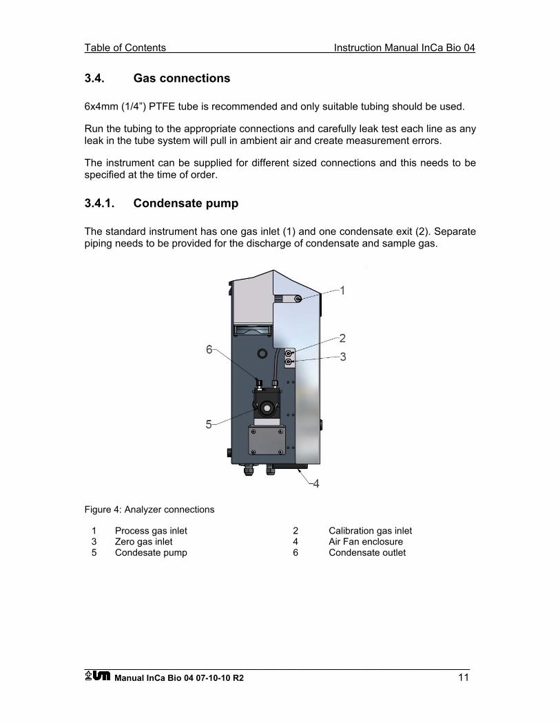
Table of Contents Instruction Manual InCa Bio 04
___________________________________________________________________ Manual InCa Bio 04 07-10-10 R2 11
3.4. Gas connections
6x4mm (1/4”) PTFE tube is recommended and only suitable tubing should be used.
Run the tubing to the appropriate connections and carefully leak test each line as any leak in the tube system will pull in ambient air and create measurement errors.
The instrument can be supplied for different sized connections and this needs to be specified at the time of order.
3.4.1. Condensate pump
The standard instrument has one gas inlet (1) and one condensate exit (2). Separate piping needs to be provided for the discharge of condensate and sample gas.
Figure 4: Analyzer connections
1 Process gas inlet 2 Calibration gas inlet 3 Zero gas inlet 4 Air Fan enclosure 5 Condesate pump 6 Condensate outlet
Instruction Manual InCa Bio 04 contents
___________________________________________________________________ 12 Manual InCa Bio 04 07-10-10 R2
Instruments with the calibration gas option will have two additional connections (2-3) and is calibrated with zero gas (air) only if supplied without these conections.
For more information about calibration gas refer to section 4
Important: The calibration gas input pressure must not exceed 70 mbar (28”H2O or 1 PSIG).
3.4.2. Air operated valve and jet pump connections
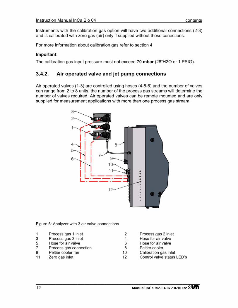
Air operated valves (1-3) are controlled using hoses (4-5-6) and the number of valves can range from 2 to 8 units, the number of the process gas streams will determine the number of valves required. Air operated valves can be remote mounted and are only supplied for measurement applications with more than one process gas stream.
Figure 5: Analyzer with 3 air valve connections
1 Process gas 1 inlet 2 Process gas 2 inlet 3 Process gas 3 inlet 4 Hose for air valve 5 Hose for air valve 6 Hose for air valve 7 Process gas connection 8 Peltier cooler 9 Peltier cooler fan 10 Calibration gas inlet 11 Zero gas inlet 12 Control valve status LED’s
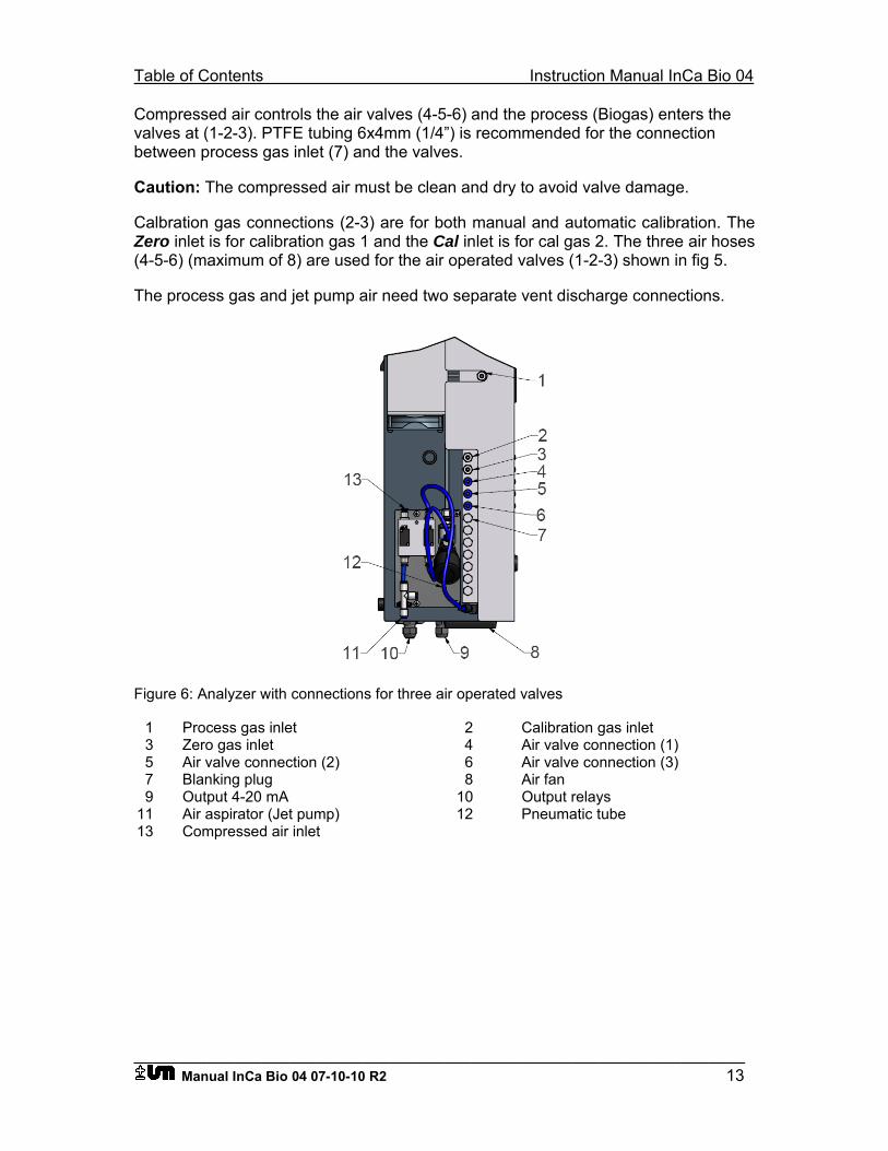
Table of Contents Instruction Manual InCa Bio 04
___________________________________________________________________ Manual InCa Bio 04 07-10-10 R2 13
Compressed air controls the air valves (4-5-6) and the process (Biogas) enters the valves at (1-2-3). PTFE tubing 6x4mm (1/4”) is recommended for the connection between process gas inlet (7) and the valves.
Caution: The compressed air must be clean and dry to avoid valve damage.
Calbration gas connections (2-3) are for both manual and automatic calibration. The Zero inlet is for calibration gas 1 and the Cal inlet is for cal gas 2. The three air hoses (4-5-6) (maximum of 8) are used for the air operated valves (1-2-3) shown in fig 5.
The process gas and jet pump air need two separate vent discharge connections.
Figure 6: Analyzer with connections for three air operated valves
1 Process gas inlet 2 Calibration gas inlet 3 Zero gas inlet 4 Air valve connection (1) 5 Air valve connection (2) 6 Air valve connection (3) 7 Blanking plug 8 Air fan 9 Output 4-20 mA 10 Output relays 11 Air aspirator (Jet pump) 12 Pneumatic tube 13 Compressed air inlet
Instruction Manual InCa Bio 04 contents
___________________________________________________________________ 14 Manual InCa Bio 04 07-10-10 R2
3.5. Power supply
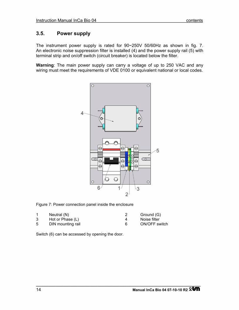
The instrument power supply is rated for 90~250V 50/60Hz as shown in fig. 7. An electronic noise suppression filter is installed (4) and the power supply rail (5) with terminal strip and on/off switch (circuit breaker) is located below the filter.
Warning: The main power supply can carry a voltage of up to 250 VAC and any wiring must meet the requirements of VDE 0100 or equivalent national or local codes.
Figure 7: Power connection panel inside the enclosure
1 Neutral (N) 2 Ground (G) 3 Hot or Phase (L) 4 Noise filter 5 DIN mounting rail 6 ON/OFF switch
Switch (6) can be accessed by opening the door.
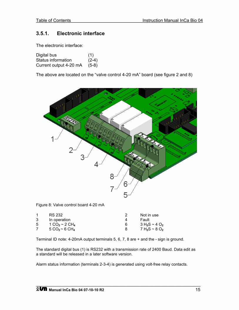
Table of Contents Instruction Manual InCa Bio 04
___________________________________________________________________ Manual InCa Bio 04 07-10-10 R2 15
3.5.1. Electronic interface
The electronic interface:
Digital bus (1) Status information (2-4) Current output 4-20 mA (5-8)
The above are located on the “valve control 4-20 mA” board (see figure 2 and 8)
Figure 8: Valve control board 4-20 mA
1 RS 232 2 Not in use 3 In operation 4 Fault 5 1 CO2 ~ 2 CH4 6 3 H2S ~ 4 O2 7 5 CO2 ~ 6 CH4 8 7 H2S ~ 8 O2
Terminal ID note: 4-20mA output terminals 5, 6, 7, 8 are + and the - sign is ground.
The standard digital bus (1) is RS232 with a transmission rate of 2400 Baud. Data edit as a standard will be released in a later software version.
Alarm status information (terminals 2-3-4) is generated using volt-free relay contacts.
Instruction Manual InCa Bio 04 contents
___________________________________________________________________ 16 Manual InCa Bio 04 07-10-10 R2
Relay conacts: Terminal block K0 = Service request (Future function) Terminal block K1 = Fault Terminal block K2 = Operation Terminal wiring: 1 - 2 Contacts normally closed 2 - 3 Contacts normally open A maximum of 8 galvanically isolated 4-20 mA outputs are available and dual outputs are provided per removable terminal block (terminals 5-6-7-8) fig.8.
The output signals are configured to provide additional stauts information: 0.0 mA = Broken cable or instrument powered off 3.2 mA = Fault 4-20 mA = No fault (normal measuring range) > 20 mA = Over-range condition
Table of Contents Instruction Manual InCa Bio 04
___________________________________________________________________ Manual InCa Bio 04 07-10-10 R2 17
4. Calibration
Calibration is required depending on the required measurement accuracy shorter calibration intervals will eliminate any drift and generally provide higher accuracies. Ambient air (gas 1) is used and calibration gas (gas 2) with a certified concentration.
4.1. Methane and Oxygen
For methane and oxygen the ambient air (gas 1) is used as a zero/span and the measurement is very stable between calibrations with very little drift.
4.2. CO2 and H2S
For CO2 calibration a certified calibration gas is required with a similar composition to the user’s process gas stream.
Gas composition examples:
Gas 1 (Ambient air) CO2 0.0 vol% CH4 0.0 vol% H2S 0.0 ppm O2 20.9 vol%
Gas 2 (Gas mixture) CO2 40.0 vol% (20 - 60 vol%) CH4 60.0 vol% (35 - 65 vol%) H2S 25 ppm (10 - 35 ppm) O2 0.0 vol% (0.0 vol%)
The amount of H2S in the process gas can be considerably higher than 25ppm, up to 3000 ppm but a special routine configures the concentration to suit the sensor.
Instruction Manual InCa Bio 04 contents
___________________________________________________________________ 18 Manual InCa Bio 04 07-10-10 R2
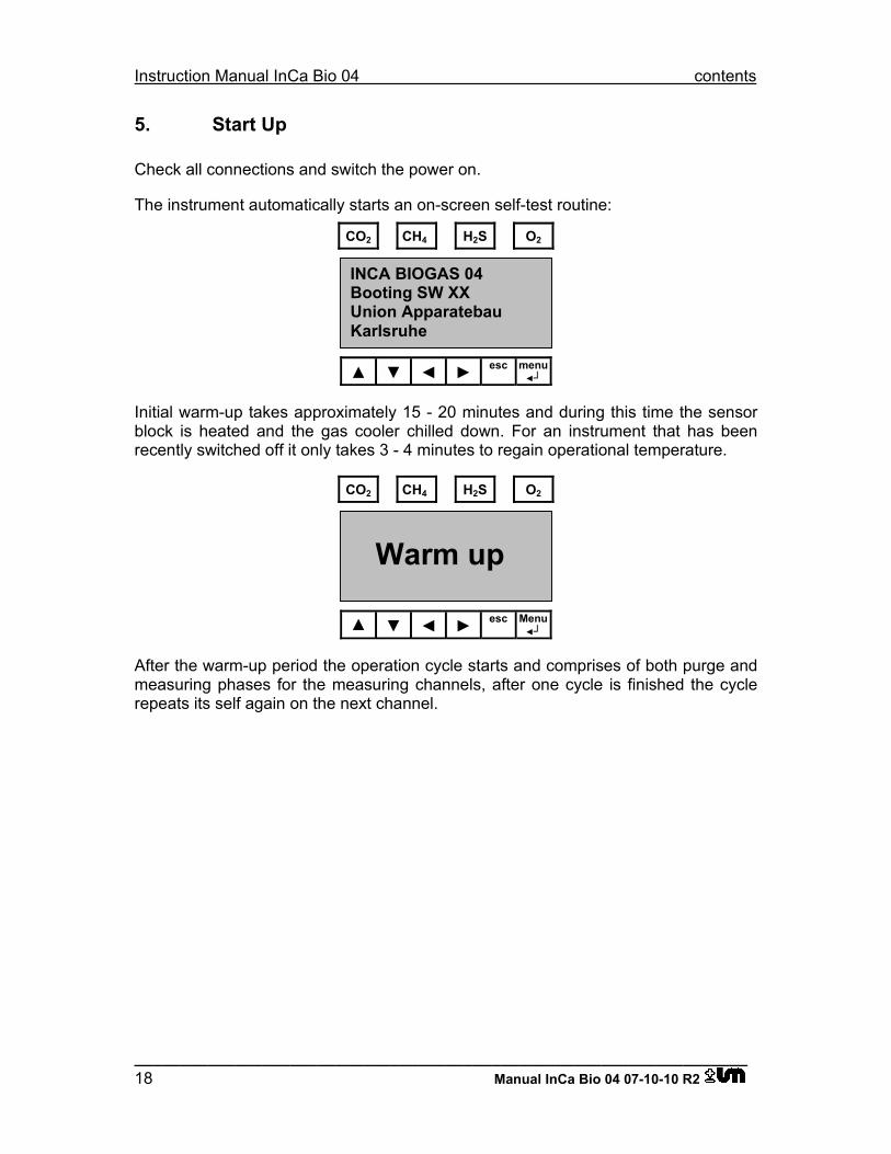
5. Start Up
Check all connections and switch the power on.
The instrument automatically starts an on-screen self-test routine:
CO2 CH4 H2S O2
▲ ▼ ◄ ► esc menu◄┘
Initial warm-up takes approximately 15 - 20 minutes and during this time the sensor block is heated and the gas cooler chilled down. For an instrument that has been recently switched off it only takes 3 - 4 minutes to regain operational temperature.
CO2 CH4 H2S O2
▲ ▼ ◄ ► esc Menu◄┘
After the warm-up period the operation cycle starts and comprises of both purge and measuring phases for the measuring channels, after one cycle is finished the cycle repeats its self again on the next channel.
Warm up
INCA BIOGAS 04 Booting SW XX Union Apparatebau Karlsruhe
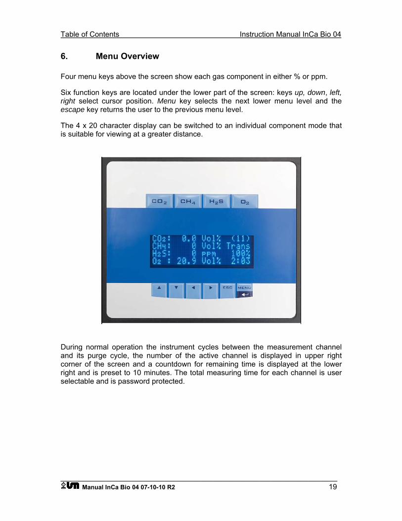
Table of Contents Instruction Manual InCa Bio 04
___________________________________________________________________ Manual InCa Bio 04 07-10-10 R2 19
6. Menu Overview
Four menu keys above the screen show each gas component in either % or ppm.
Six function keys are located under the lower part of the screen: keys up, down, left, right select cursor position. Menu key selects the next lower menu level and the escape key returns the user to the previous menu level.
The 4 x 20 character display can be switched to an individual component mode that is suitable for viewing at a greater distance.
During normal operation the instrument cycles between the measurement channel and its purge cycle, the number of the active channel is displayed in upper right corner of the screen and a countdown for remaining time is displayed at the lower right and is preset to 10 minutes. The total measuring time for each channel is user selectable and is password protected.
Instruction Manual InCa Bio 04 contents
___________________________________________________________________ 20 Manual InCa Bio 04 07-10-10 R2
CO2 CH4 H2S O2
▲ ▼ ◄ ► esc Menu◄┘
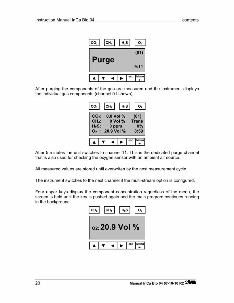
After purging the components of the gas are measured and the instrument displays the individual gas components (channel 01 shown).
CO2 CH4 H2S O2
▲ ▼ ◄ ► esc Menu◄┘
After 5 minutes the unit switches to channel 11. This is the dedicated purge channel that is also used for checking the oxygen sensor with an ambient air source.
All measured values are stored until overwriten by the next measurement cycle.
The instrument switches to the next channel if the multi-stream option is configured.
Four upper keys display the component concentration regardless of the menu, the screen is held until the key is pushed again and the main program continues running in the background.
CO2 CH4 H2S O2
▲ ▼ ◄ ► esc Menu◄┘
O2: 20.9 Vol %
CO2: 0,0 Vol % (01) CH4: 0 Vol % TransH2S: 0 ppm 0%O2 : 20,9 Vol % 8:59
(01)
Purge 9:11
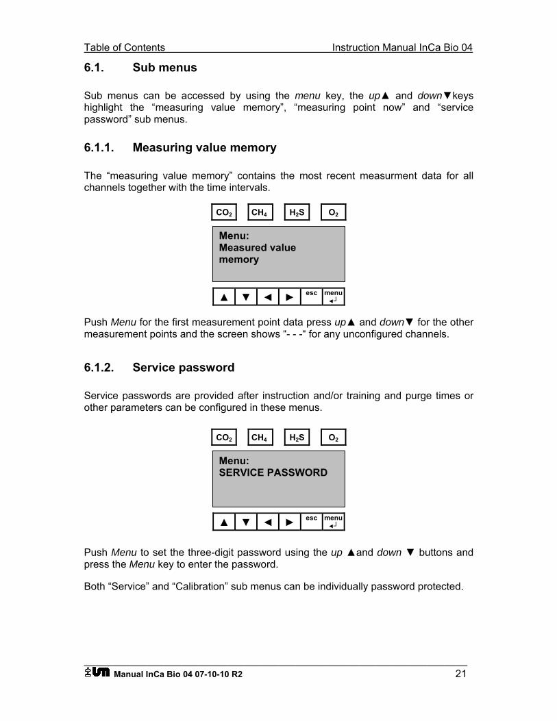
Table of Contents Instruction Manual InCa Bio 04
___________________________________________________________________ Manual InCa Bio 04 07-10-10 R2 21
6.1. Sub menus
Sub menus can be accessed by using the menu key, the up▲ and down▼keys highlight the “measuring value memory”, “measuring point now” and “service password” sub menus.
6.1.1. Measuring value memory
The “measuring value memory” contains the most recent measurment data for all channels together with the time intervals.
CO2 CH4 H2S O2
▲ ▼ ◄ ► esc menu◄┘
Push Menu for the first measurement point data press up▲ and down▼ for the other measurement points and the screen shows “- - -“ for any unconfigured channels.
6.1.2. Service password
Service passwords are provided after instruction and/or training and purge times or other parameters can be configured in these menus.
CO2 CH4 H2S O2
▲ ▼ ◄ ► esc menu◄┘
Push Menu to set the three-digit password using the up ▲and down ▼ buttons and press the Menu key to enter the password.
Both “Service” and “Calibration” sub menus can be individually password protected.
Menu: SERVICE PASSWORD
Menu: Measured value memory
Instruction Manual InCa Bio 04 contents
___________________________________________________________________ 22 Manual InCa Bio 04 07-10-10 R2
Caution: Care should be used when working in the service menu as any system data that is changed in error can cause a system malfunction.
The “Service” menu contains the following functions: (PASSWORD I) “MEASUREMENT NOW” “NUMBER OF MEASURMENT POINTS” “MEASURING TIME PER MEASUREMENT POINT” “HOLD TIME PER MEASUREMENT POINT”
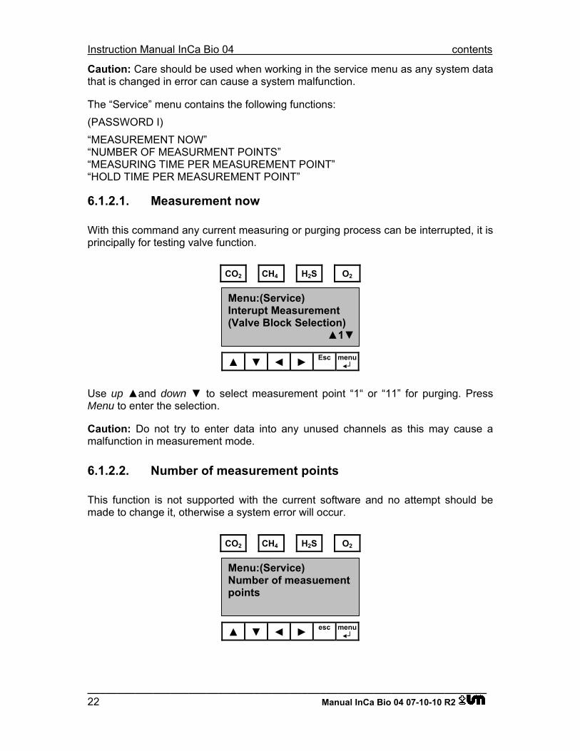
6.1.2.1. Measurement now
With this command any current measuring or purging process can be interrupted, it is principally for testing valve function.
CO2 CH4 H2S O2
▲ ▼ ◄ ► Esc menu◄┘
Use up ▲and down ▼ to select measurement point “1“ or “11” for purging. Press Menu to enter the selection.
Caution: Do not try to enter data into any unused channels as this may cause a malfunction in measurement mode.
6.1.2.2. Number of measurement points
This function is not supported with the current software and no attempt should be made to change it, otherwise a system error will occur.
CO2 CH4 H2S O2
▲ ▼ ◄ ► esc menu◄┘
Menu:(Service) Number of measuement points
Menu:(Service) Interupt Measurement (Valve Block Selection) ▲1▼
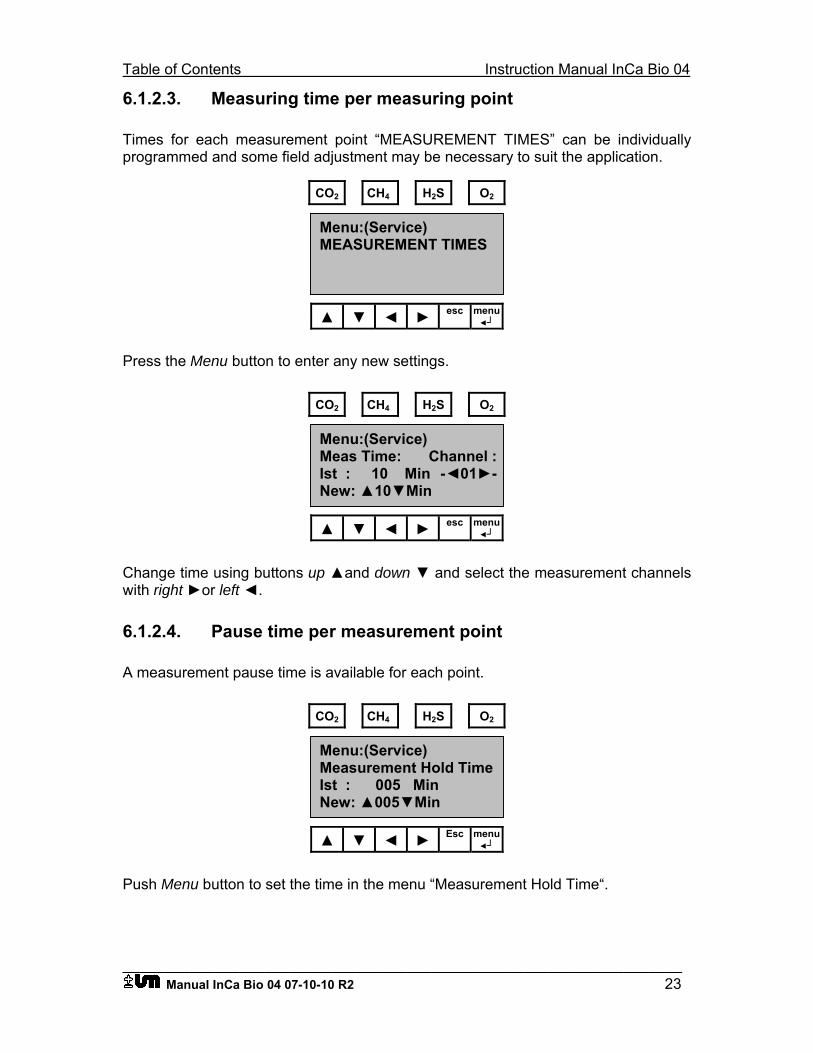
Table of Contents Instruction Manual InCa Bio 04
___________________________________________________________________ Manual InCa Bio 04 07-10-10 R2 23
6.1.2.3. Measuring time per measuring point
Times for each measurement point “MEASUREMENT TIMES” can be individually programmed and some field adjustment may be necessary to suit the application.
CO2 CH4 H2S O2
▲ ▼ ◄ ► esc menu◄┘
Press the Menu button to enter any new settings.
CO2 CH4 H2S O2
▲ ▼ ◄ ► esc menu◄┘
Change time using buttons up ▲and down ▼ and select the measurement channels with right ►or left ◄.
6.1.2.4. Pause time per measurement point
A measurement pause time is available for each point.
CO2 CH4 H2S O2
▲ ▼ ◄ ► Esc menu◄┘
Push Menu button to set the time in the menu “Measurement Hold Time“.
Menu:(Service) Measurement Hold Time Ist : 005 Min New: ▲005▼Min
Menu:(Service) Meas Time: Channel :Ist : 10 Min -◄01►-New: ▲10▼Min
Menu:(Service) MEASUREMENT TIMES
Instruction Manual InCa Bio 04 contents
___________________________________________________________________ 24 Manual InCa Bio 04 07-10-10 R2
6.1.2.5. Calibration
The “Calibration“ menu contains the following functions:
(PASSWORD II)
“AUTOCAL“
“CALGAS 1“
“CALGAS 2“
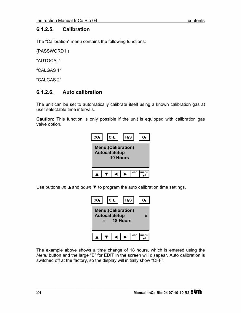
6.1.2.6. Auto calibration
The unit can be set to automatically calibrate itself using a known calibration gas at user selectable time intervals.
Caution: This function is only possible if the unit is equipped with calibration gas valve option.
CO2 CH4 H2S O2
▲ ▼ ◄ ► esc menu◄┘
Use buttons up ▲and down ▼ to program the auto calibration time settings.
CO2 CH4 H2S O2
▲ ▼ ◄ ► esc menu◄┘
The example above shows a time change of 18 hours, which is entered using the Menu button and the large “E” for EDIT in the screen will disapear. Auto calibration is switched off at the factory, so the display will initially show “OFF”.
Menu:(Calibration) Autocal Setup E = 18 Hours
Menu:(Calibration) Autocal Setup 10 Hours
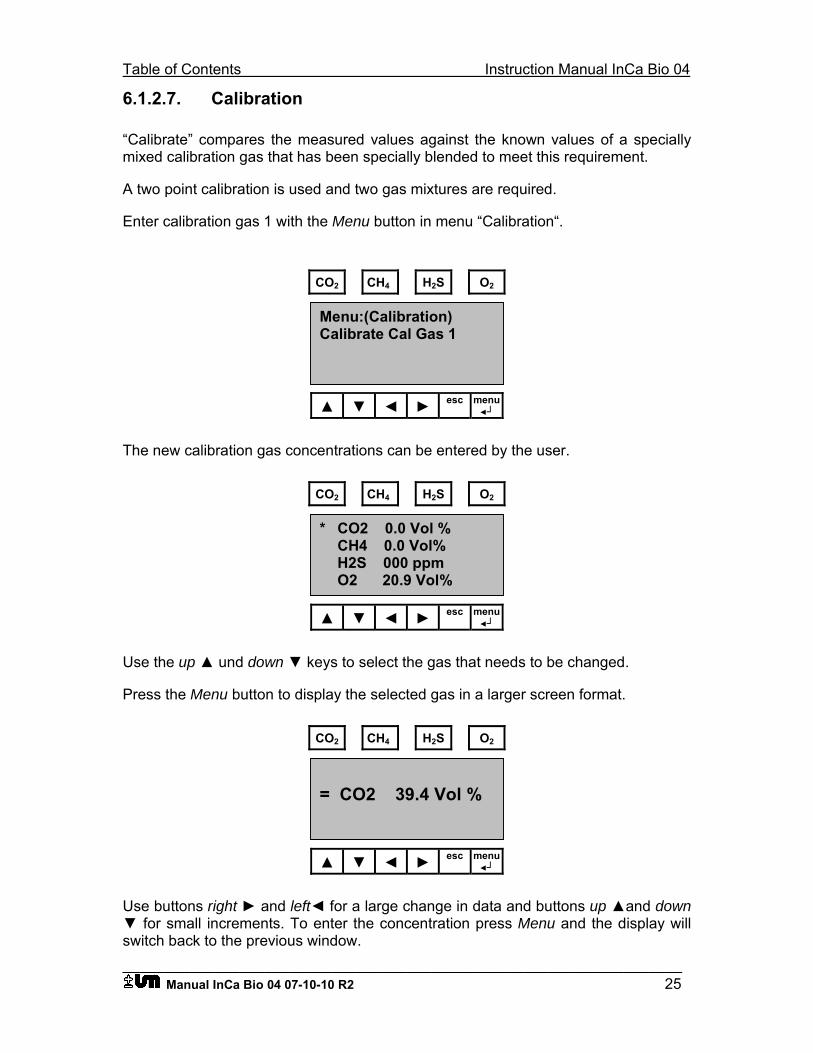
Table of Contents Instruction Manual InCa Bio 04
___________________________________________________________________ Manual InCa Bio 04 07-10-10 R2 25
6.1.2.7. Calibration
“Calibrate” compares the measured values against the known values of a specially mixed calibration gas that has been specially blended to meet this requirement.
A two point calibration is used and two gas mixtures are required.
Enter calibration gas 1 with the Menu button in menu “Calibration“.
CO2 CH4 H2S O2
▲ ▼ ◄ ► esc menu◄┘
The new calibration gas concentrations can be entered by the user.
CO2 CH4 H2S O2
▲ ▼ ◄ ► esc menu◄┘
Use the up ▲ und down ▼ keys to select the gas that needs to be changed.
Press the Menu button to display the selected gas in a larger screen format.
CO2 CH4 H2S O2
▲ ▼ ◄ ► esc menu◄┘
Use buttons right ► and left◄ for a large change in data and buttons up ▲and down ▼ for small increments. To enter the concentration press Menu and the display will switch back to the previous window.
= CO2 39.4 Vol %
* CO2 0.0 Vol % CH4 0.0 Vol% H2S 000 ppm O2 20.9 Vol%
Menu:(Calibration) Calibrate Cal Gas 1
Instruction Manual InCa Bio 04 contents
___________________________________________________________________ 26 Manual InCa Bio 04 07-10-10 R2
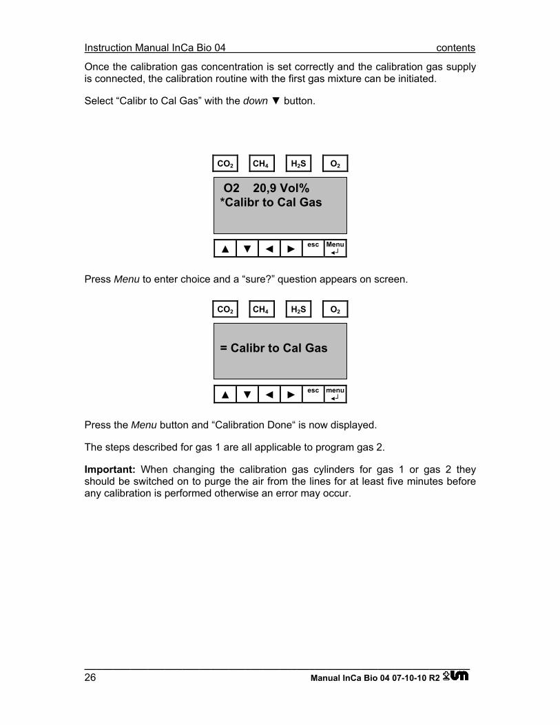
Once the calibration gas concentration is set correctly and the calibration gas supply is connected, the calibration routine with the first gas mixture can be initiated.
Select “Calibr to Cal Gas” with the down ▼ button.
CO2 CH4 H2S O2
▲ ▼ ◄ ► esc Menu◄┘
Press Menu to enter choice and a “sure?” question appears on screen.
CO2 CH4 H2S O2
▲ ▼ ◄ ► esc menu◄┘
Press the Menu button and “Calibration Done“ is now displayed.
The steps described for gas 1 are all applicable to program gas 2.
Important: When changing the calibration gas cylinders for gas 1 or gas 2 they should be switched on to purge the air from the lines for at least five minutes before any calibration is performed otherwise an error may occur.
= Calibr to Cal Gas
O2 20,9 Vol% *Calibr to Cal Gas
Table of Contents Instruction Manual InCa Bio 04
___________________________________________________________________ Manual InCa Bio 04 07-10-10 R2 27
7. Status Codes
The status codes indicate a malfunction has occured during operation. Some of the codes can be rectified by the user - other codes are more serious and have to be reported for factory advice.
Status 40: AD error on Peltier element
Temperature sensor on Peltier element defective
Status 90: General bus error
Status 91: Bus error
Relay card not recognized
Status 92: Bus error
Infrared measurement not recognized
Status N.C.: Not connected or defective
- applies to both optical and chemical sensors
Status 60: Temperature sensor broken
Status 53: Lamp 1 defective
Status 54: Lamp 2 defective
Status 21: Zero gas error CO2
Status 22: Zero gas error CH4
Status 24: Span gas error C02
Status 25: Span gas error CH4
Status 30: Operating temperature not reached
Status P+/P+: Pump status
Instruction Manual InCa Bio 04 contents
___________________________________________________________________ 28 Manual InCa Bio 04 07-10-10 R2
8. Maintenance and Service
The instrument is modular in construction and any maintenance or service can be performed by the user with simple tools.
8.1. Pump life
In normal operation the life of both diaphragm pumps is approximately 16K hours (2 years). Note: The gas pump module is equipped with a solenoid valve to prevent any backflow of air into the system.
The air pump does not have a valve and both units can be obtained as a spare part and are easily replaced by the user and new tube connections are also supplied with the pumps.
8.2. Electro chemical sensor life
The life time of the chemical sensors (H2S and O2) depend on gas concentration and the average life of the H2S sensor is approximately 18 months when operating on normal process gas concentrations. Average O2 sensor life is more than a year at 20.9% oxygen.
A pre-calibrated electrochemical sensor can be supplied as a spare part, allowing the instrument to be quickly returned to service by the user.
8.3. Optical sensor life
The CH4 and CO2, optical sensors have an almost an unlimited life but are sensitive to dirt and humidity. In most cases the complete sensor block with heater and IR detectors will need replacement and the complete replacement module can be installed by the user.
8.4. Condensate pump
The peristaltic (hose) pump is a consumable part and should be replaced every 24 month by the user. The hose, which can be damaged by abrasives, is available as a spare part.
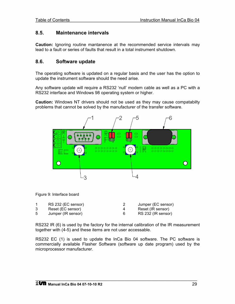
Table of Contents Instruction Manual InCa Bio 04
___________________________________________________________________ Manual InCa Bio 04 07-10-10 R2 29
8.5. Maintenance intervals
Caution: Ignoring routine mantanence at the recommended service intervals may lead to a fault or series of faults that result in a total instrument shutdown.
8.6. Software update
The operating software is updated on a regular basis and the user has the option to update the instrument software should the need arise.
Any software update will require a RS232 ‘null’ modem cable as well as a PC with a RS232 interface and Windows 98 operating system or higher.
Caution: Windows NT drivers should not be used as they may cause compatabilty problems that cannot be solved by the manufacturer of the transfer software.
Figure 9: Interface board
1 RS 232 (EC sensor) 2 Jumper (EC sensor) 3 Reset (EC sensor) 4 Reset (IR sensor) 5 Jumper (IR sensor) 6 RS 232 (IR sensor)
RS232 IR (6) is used by the factory for the internal calibration of the IR measurement together with (4-5) and these items are not user accessable.
RS232 EC (1) is used to update the InCa Bio 04 software. The PC software is commercially available Flasher Software (software up date program) used by the microprocessor manufacturer.
Instruction Manual InCa Bio 04 contents
___________________________________________________________________ 30 Manual InCa Bio 04 07-10-10 R2
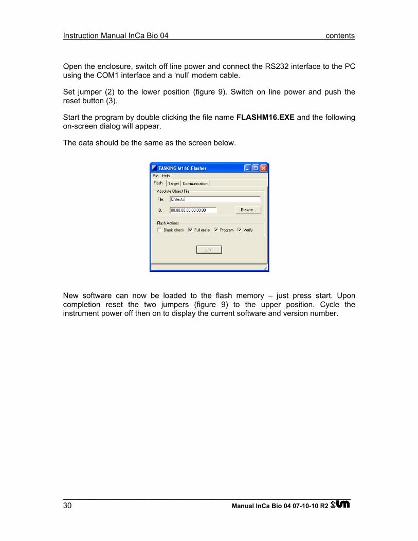
Open the enclosure, switch off line power and connect the RS232 interface to the PC using the COM1 interface and a ‘null’ modem cable.
Set jumper (2) to the lower position (figure 9). Switch on line power and push the reset button (3).
Start the program by double clicking the file name FLASHM16.EXE and the following on-screen dialog will appear.
The data should be the same as the screen below.
New software can now be loaded to the flash memory – just press start. Upon completion reset the two jumpers (figure 9) to the upper position. Cycle the instrument power off then on to display the current software and version number.
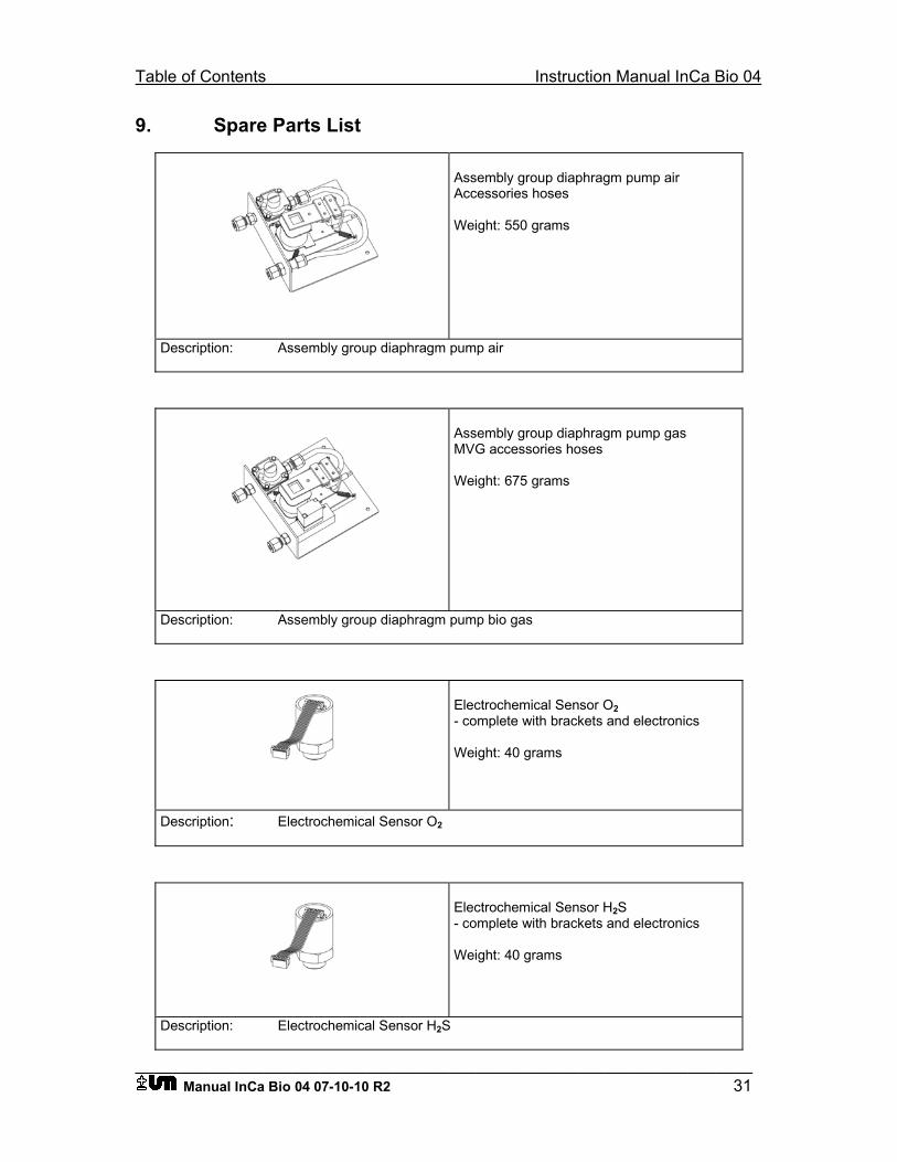
Table of Contents Instruction Manual InCa Bio 04
___________________________________________________________________ Manual InCa Bio 04 07-10-10 R2 31
9. Spare Parts List
Assembly group diaphragm pump air Accessories hoses Weight: 550 grams
Description: Assembly group diaphragm pump air
Assembly group diaphragm pump gas MVG accessories hoses Weight: 675 grams
Description: Assembly group diaphragm pump bio gas
Electrochemical Sensor O2 - complete with brackets and electronics Weight: 40 grams
Description: Electrochemical Sensor O2
Electrochemical Sensor H2S - complete with brackets and electronics Weight: 40 grams
Description: Electrochemical Sensor H2S
Instruction Manual InCa Bio 04 contents
___________________________________________________________________ 32 Manual InCa Bio 04 07-10-10 R2
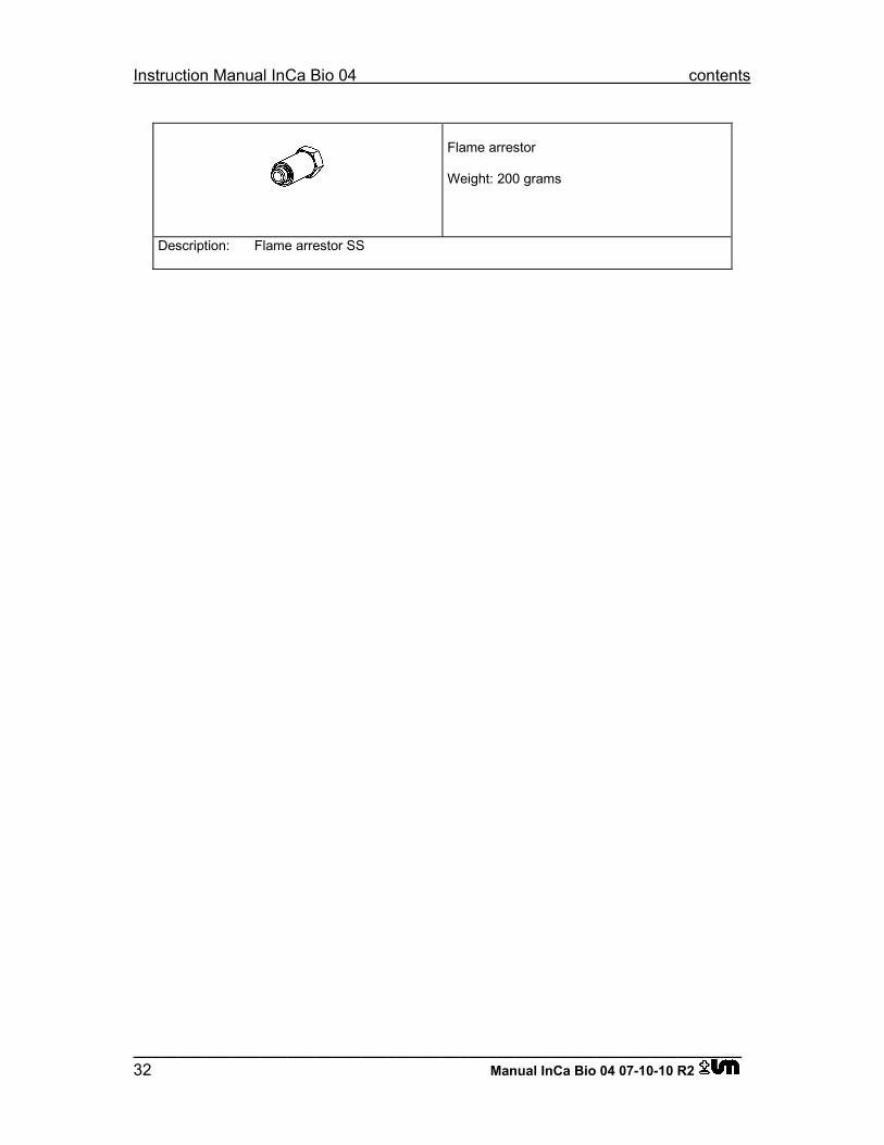
Flame arrestor Weight: 200 grams
Description: Flame arrestor SS