Embed Size (px)
Citation preview

MANUAL FOR CONSTRUCTION,
MAINTENANCE AND
INSPECTION OF TRACK
MW 4
CONSTRUCTION AND MAINTENANCE PRACTICE


Section I Contents
Eff. Date Page No.
Subpart A — General
1.0 Scope of subpart. 2-12 -
Subpart B - Road and Right of Way 33.0 Drainage. 2-12 - 35.0 Cross section. 2-12 - 37.0 Vegetation. 2-12 - 39.0 Signs and posts 2-12 - 41.0 Highway grade crossings. 41.1 Authority for protection 2-12 - 41.2 Forms of protection 2-12 - 41.3 Construction 2-12 - 41.4 Maintenance 2-12 - 41.5 Conduct of work 2-12 - 43.0 Communication and signal lines.
2-12 -
Subpart C - Track Geometry
53.0 Gage. 53.1 Standards for gage 2-12 - 53.2 Maintenance of gage 2-12 - 55.0 Alinement. 55.1 Maintenance of alinement 2-12 - 55.2 String lining curves 2-12 - 55.3 Referencing track for lining 2-12 - 57.0 Curvature, elevation and speed. 57.1 General 2-12 - 57.2 Elevation 2-12 - 59.1 Spirals and elevation runoffs.
59.1 Spirals 2-12 - 59.2 Elevation runoffs 2-12 - 59.3 Marking 2-12 - 61.0 Curve data records. 2-12 - 62.0 Clearances and track centers. 62.1 Track centers 2-12 - 62.2 lntertrack clearance limiting 2-12 -
objects 62.3 Other clearance limiting objects 2-12 - 63.0 Grades 63.1 Limitations 2-12 - 63.2 Compensation on curves 2-12 - 63.3 Vertical curves 2-12 - 64.0 Track surface. 64.1 General 2-12 - 64.2 Maintenance 2-12 - 64.3 Special attention 2-12 - 64.4 Raising track 2-12 - 70.0 Secondary, yard and industrial tracks, and sidings. 70.1 General 2-12 - 70.2 Turnouts 2-12 - 70.3 Curvature 2-12 - 70.4 Spirals 2-12 - Subpart D - Track Structure 101.0 Material 101.1 General 2-12 - 101.2 Handling and care 2-12 - 101.3 Classification 2-12 - 103.0 Ballast. 103.1 General 2-12 - 103.2 Distribution 2-12 - 103.3 Cross section 2-12 - 103.4 Ballast cleaning 2-12 - 103.5 Size and gradation 2-12 -

107.0 Cross ties-wood. 107.1 Size 2-12 - 107.2 Use 2-12 - 107.3 Installation 2-12 - 107.4 Damage to ties 2-12 - 108.0 Switch ties. 2-12 - 109.0 Bridge ties. 2-12 - 113.0 Rails. 113.1 General 2-12 - 113.2 Classification and Identification 2-12 - 113.3 Service assignments 2-12 - 113.4 Disposition and shipment 2-12 - 113.5 Grading and marking 2-12 -
rail for reuse 113.6 Transposing and turning rail 2-12 -
on curves 113.7 Distribution 2-12 - 113.8 Preparation and care 2-12 - 113.9 Laying jointed rails 2-12 - 113.10 Bolt holes 2-12 - 113.11 Cutting rail 2-12 - 113.12 Rails bonded for track circuits 2-12 - 119.0 Continuous welded rail (CWR). 119.1 Installation Procedures 2-12 - 119.2 Rail anchoring 2-12 - 119.3 Preventative Maintenance 2-12 - 119.4 Monitoring Curve Movement 2-12 - 119.5Temporary Speed Restrictions 2-12 - 119.6Rail Joint Inspections 2-12 - 119.7Extreme Weather Inspections 2-12 - 119.8 Training 2-12 - 119.9 Recordkeeping 2-12 - 119.10 Tables/Diagrams 2-12 - 121.0 Rail joints. 121.1 General 2-12 - 121.2 Bolted rail joints 2-12 -
122.0 Insulated rail joints. 122.1 Stagger of insulated joints 2-12 - 122.2 Location of insulated joints 2-12 - 122.3 Application of continuous 2-12 -
insulated joints 122.4 Application of bonded 2-12 -
insulated joints 122.5 Care of joints 2-12 - 123.0 Tie plates. 123.1 Use 2-12 - 123.2 Placement 2-12 - 123.3 Tie pads 2-12 - 125.0 Rail anchors. 125.1 Number required 2-12 - 125.2 Application 2-12 - 125.3 Maintenance 2-12 - 125.4 Assignment 2-12 - 127.0 Spiking. 127.1 Number required 2-12 - 127.2 Application 2-12 - 132.0 Track crossings. 132.1 Use 2-12 - 132.2 Installation 2-12 - 132.3 Maintenance 2-12 - 133.0 Turnouts and crossovers. 133.1 Use 2-12 - 133.2 Speeds through turnouts 2-12 - 133.3 Installation 2-12 - 135.0 Switches. 135.1 Use 2-12 - 135.2 Maintenance 2-12 - 135.3 Reduction in wear 2-12 - 135.4 Protection 2-12 - 135.5 Inspection 2-12 - 137.0 Frogs. 137.1 Use 2-12 -

137.2 Maintenance 2-12 - 143.0 Frog guard rails. 143.1 General 2-12 - 143.2 Use 2-12 - 143.3 Length 2-12 - 143.4 Gage and distance 2-12 - 143.5 Application 2-12 - 145.0 Inner bridge guard rails. 145.1 General 2-12 - 145.2 Use 2-12 - 145.3 Material 2-12 - 145.4 Application 2-12 - 145.5 Inspection 2-12 - 201.0Switch Operating mechanisms 201.1 Use 2-12 - 201.2 Spring switches 2-12 - 201.3 Application of switch stands 2-12 - 201.4 Locations of switch stands 2-12 - 201.5 Padlocks 2-12 - 201.6 Maintenance 2-12 - 202.0 Switch point position indicators. 202.1 General 2-12 - 202.2 Application 2-12 - 202.3 Maintenance 2-12 - 202.4 Position indication 2-12 - 203.0 Hot box detectors. 203.1 Application 2-12 - 203.2 Track condition 2-12 - 203.3 Track work in vicinity 2-12 - 203.4 Interference by metal 2-12 - 205.0 Derails
205.1 Position 2-12 - 205.2 Use of derails 2-12 - 205.3 Types of derails 2-12 - 205.4 Application 2-12 - 205.5 Operation of derails 2-12 - 205.6 Position indication 2-12 - 205.7 Maintenance 2-12 - 206.0 Rail Lubricators. 2-12 - Index — Standard Plans. 2-12 -
Section II
Contents
PennDOT track specifications
Section III Contents
Eff. Date Page No.
Section IV Contents
Eff. Date Page No.

Subpart A—General §1.0 Scope of part. Eff. 2-12
(a) This provides economical standards for the construction and maintenance of track. It is for the guidance of Division Engineers, Supervisors-Track, Engineer Corps., Inspectors, Foremen- Track, other Maintenance of Way forces, contractors and others building or repairing track. Any portions of this part may be included in a contract and carry the same force as specifications, when so used.
(b) It is not the intent of this part to establish arbitrary procedures or values, but serve as a guide which must be considered in the light of experience and the requirements of the service.
Subpart B—Roadbed and Right of Way. §33.0 Drainage. Eff. 2-12
(a) Drainage is of prime importance for economical maintenance of track. Water mixing with materials of the roadbed tends to make the entire track structure unstable in varying degrees depending on the kind of material and the quantity and flow of water.
(b) Water seeping or flowing toward the track should be conducted across the roadbed or be intercepted and diverted before it reaches the roadbed.
(c) Water falling upon the roadbed should be quickly drained. (d) Adequate cross drains should be maintained, particularly where bridges, road crossings,
and sags interfere with longitudinal drainage. (e) Geotextiles should be used as per instructions of the Chief Engineer M.W., but not in lieu
of good drainage. (f) Maintenance of drainage systems must satisfy the requirements of §213.33.
§35.0 Cross section. Eff. 2-12 Roadbeds, enbankments and excavations should be constructed in accordance with Standard Plan 70003-( ) and thereafter so maintained. Deviation from approved cross sections should not be made without authorization by the Chief Engineer M.W. §37.0 Vegetation. Eff. 2-12
(a) Growth of vegetation should be encouraged on slopes of embankments, cuts and deep ditches to prevent erosion.
(b) Vegetation growth must be controlled in accordance with the requirements of §213.37. §39.0 Signs and posts. Eff. 2-12 Track signs and posts must be placed and maintained in accordance with Standard Plans and special instructions. They should be maintained in their proper places and kept plumb. §41.0 Highway grade crossings. §41.1 Authority for protection. Eff. 2-12

In addition to signals prescribed in "Rules of the Transportation Department" public grade crossings shall be protected according to degree of hazard, state statues, township and municipal ordinances and public service commission regulations with the sign or device approved by the governing body. §41.2 Forms of protection. Eff. 2-12
(a) Whistle signs in accordance with Standard Plan 78410-( ). (b) Highway crossing signs conforming to Standard Plan 78302-( ). (c) Automatic protection:
(1) Automatic flashing light signals and highway crossing signs conforming to Standard Signal Plan.
(2) Automatic crossing gates with flashing light signal assemblage and highway crossing sign conforming to Standard Signal Plan.
(3) Where track circuits for crossing protection are applied to sidings or yard tracks, the limits of the circuits on such tracks shall be indicated by a "CC" sign or by a yellow stripe approximately 10 inches wide painted on the inside and outside of the head, web and base of both rails, which must be kept clear of snow, ice, dirt and weeds, and must be repainted as often as necessary.
§41.3 Construction. Eff. 2-12
(a) Public and private grade crossings over Conrail tracks are to be constructed in accordance with Standard Plan 70123-( ), unless other crossing material is approved by Chief Engineer M.W.
(b) Farm crossings are to be constructed in accordance with Standard Plan 70124-( ). (c) CWR should be used in the crossing area and should be extended at least 50 feet each
side of crossing. (d) Geotextile fabric should be installed under the crossing area.
§41.4 Maintenance. Eff. 2-12
(a) All signs and other forms of protection at grade crossings must be immediately repaired or replaced when damaged.
(b) Crossing should be kept clean, and attention given to the following: (1) Drainage, sloping the surface if necessary, and constructing underground drains. (2) Surface water flowing along highway toward the railroad should be diverted
before it reaches the tracks. (3) Highway approaches to track areas should be on smooth grades without abrupt
breaks, so that low road clearance vehicles carrying large shipments, such as heavy machinery, may pass over the tracks without touching the rails or surface of crossing with their under frames.
(4) Flangeways shall be at least 2 1/2 inches wide and shall not be less than 4 inches deep. They must be kept clean at all times.
(5) Asphalt should not be placed in the flangeway opening.

(6) The view in both directions from vehicles approaching the track shall be kept as clear as practicable.
(7) When installing or making general repairs to crossings, track alinement should be fixed by transit line, string line or mechanical lining devices.
§41.5 Conduct of work. Eff. 2-12 Work on highway crossings, public streets and roads shall be done with the least inconvenience possible to highway travelers. Care must be taken to protect the work in compliance with the safety requirements and the law. Where it is necessary to construct temporary footwalks or driveways, they must be kept in a safe condition. §43.0 Communication and signal lines. Eff. 2-12
(a) When repairing and working on wire lines, all applicable safety rules must be strictly observed.
(b) All Maintenance of Way employees must observe the general condition of poles and wires along and across the tracks and right-of-way, and report any conditions needing correction, such as: broken wires, uprooted trees or broken branches in the wires, or broken or leaning poles, to responsible C.&S. employee and the Supervisor—Track.
(c) Trees near wire lines should be kept trimmed, or removed when decayed to such an extent as to be unsafe, to prevent interference with wires, or with the view of signals. Subpart C—Track Geometry. §53.0 Gage. §53.1 Standards for gage. Eff. 2-12 The Standard gage for track is to be measured between the running rails at right angles to the alinement of the track, 5/8 inch below the top of rail.
(a) Standard gage will be 4'-8 1/2" (561/2") on tangents, curves and through turnouts and crossovers except:
(1) 4'-81/4" (56 1/4") is permitted on tangents where maximum authorized speed is 60 M.P.H. or greater.
(2) 4'-9" (57") on curves over 13 degrees. (3) 4'-9" (57") on turnout runs from tangent for turnouts less than No. 8.
(b) Gage through specially fabricated trackwork, such as movable point and slip crossings, shall be as authorized by the Chief Engineer M.W.
(c) Where existing gage conforms to standards previously in effect, and is in compliance with §213.53, change need not be made until rail is renewed or out-of-face gaging is performed.
(d) Changes in prescribed gages should be made in uniform increments of not more than 1/4 inch per 31 feet of track.
(e) Gage shall be changed by suitable adjustment of the rail opposite the line rail. §53.2 Maintenance of gage. Eff. 2-12

(a) Gage shall be measured with a standard track gage or other device authorized by Chief
Engineer M.W. Track gages must be checked at frequent intervals for accuracy by the Supervisor–Track.
(b) Provided gage is uniform, the following deviations from that maintained should not be exceeded:
(1) In classes 5 and 6 track:
Tangents—Plus or minus 1/4 inch. Curves—Plus 1/2 inch to minus 1/4 inch. (2) In classes 1 through 4 track, where the rails are securely fastened to the ties and in
correct alinement:
Tangents—Plus 1/2 inch to minus 1/4 inch. Curves—Plus 3/4 inch to minus 1/4 inch.
§55.0 Alinement. Alinement consists of series of straight lengths of track, referred to as tangents, connected by simple, compound or reverse curves. §55.1 Maintenance of alinement. Eff. 2-12
(a) Outer rails of curves and field side rails on tangents should be selected as the line rails. (b) When general alinement is to be corrected, such as the removal of long swings on
tangents and the restoration of curves to circular curvature, laying out of spirals, etc., the throws should be determined from field measurements.
(1) A transit should be used to determine the corrections required on tangents. (2) The string line method should be used to determine the alinement of curves and to
calculate the required correction or throws. (c) For detail corrections of irregular line, the required throws may be determined by using a
line wire and indicator device, plotting a graph on curves, or with automatic lining equipment. (d) Alinement must be maintained within the limits prescribed in §213.55. (e) The alinement of track and elevation on curves in overhead electrified territory must not
be changed unless approved by the Division Engineer. §55.2 String lining curves. Eff. 2-12
(a) String lining of curves is based on the following principles: (1) The mid-ordinates of a curve are indicative of its degree of curvature. (2) The mid-ordinates of a circular curve are equal for chords of uniform length. (3) For practical purposes, the mid-ordinate varies directly with the degree of
curvature. (4) Where track is thrown in or out at any single station on the curve, the mid-
ordinate of the curve at the station is affected by the amount of the throw and the mid-

ordinates at the adjacent stations are automatically affected by one-half ( 1/2) of the amount, but in the opposite direction. (b) String lining of curves is a method for determining the most advantageous alinement that
can be obtained with reasonable amounts of throw. (c) Any of the established mathematical methods, such as the "Bartlett Method" or "Bracket
Method", may be used to calculate the throws of curves. All calculations should be checked to ascertain that the calculated throws will actually produce the required changes in mid-ordinates.
(d) The ARC "Curveliner" machine is an approved device for mechanically calculating the throw of curves. The operator of the "Curveliner" machine must be properly trained in its operation.
(e) Track shall be stationed for string lining on the gage side of the outer (high side) rail of the curve, with stationing marked on the web or base of the rail.
(1) Stationing shall begin at a point on tangent sufficiently far ahead to permit the measurement of any reverse curvature or "dog-leg", and continue throughout the curve to a point sufficiently far on the tangent to permit measurement of any reverse curvature on the leaving end.
(2) 31-foot stations (62 foot chords) should be used for most curves found in main tracks, in which case a midordinate of one (1) inch will indicate one (1) degree of curvature. It may be desirable to use 44 foot stations for curves under 30 minutes, or to use 22 foot stations for sharp curves.
(3) 15 foot 6 inch station lengths (31 foot chords) are to be used when determining the mid-ordinate reading for derailment notes and may to desirable for sharp curves.
(4) The practical relationship between station and chord length, mid-ordinate and degree of curvature for various stations is shown in the following table:
Degree of curvature
Station length
Chord length
Mid-ordinate
1º00’ 15’6” 31’ ¼”
1º00’ 22’ 44’ ½”
1º00’ 31’ 62’ 1”
1º00’ 44’ 88’ 2”
(f) Mid-ordinates should be measured from the gage side of the rail, 5/8 inch down from top of rail, to the string in sixteenths (16ths) of an inch.
(1) String line holders or offset blocks should be used to position the string a distance of one (1) inch away from the gage line of the rail, so as to permit measurement of any reverse curvature. A typical string line holder is shown in figure 1 (next page).
(2) Mid-ordinate measurements should be taken with the string line pulled taut. not affected by the wind, and with the string line holders and the scale held horizontal and perpendicular to the gage.

(3) When using a conventional rule to measure the mid-ordinate, the actual scale reading should be recorded and a correction made to compensate for the 1 inch offset of the string line from the rail when calculations are made, to avoid field errors. Direct compensated readings of midordinates may be recorded by the use of a scale similar to that shown in figure 2 (next page). (g) Track center distances should be measured and recorded at least every five (5) stations in
two or more track territory, and more frequently where close track centers are encountered. The distance from center line of track to any obstruction which might interfere with the lining of the curve should be measured and recorded so that limiting throws for these tight spots may be determined. Attention should be given to avoid reducing track centers.
(h) The location of both ends of each elevation runoff should be noted so that the relationship between spirals and runoffs can be maintained.

§55.3 Referencing track for lining. Eff. 2-12
(a) In single track territory stakes shall be used to mark the desired alinement. Stakes may be used in "Third Rail Territory" or at other locations in multiple track territory where their use may be expedient.
(b) A "scratch" board or rod may be effectively used to mark required throws for curves on multiple tracks. These are devices for referencing existing alinement of the track to be lined to an adjacent track, which must not be disturbed until the lining operation has been completed:

(1) Scratch boards have one notched end, to be placed on the head of a rail, and have
a scriber or sharpened spike on the other end for "scratch marking" ties on the adjacent track. There are usually several notches to permit use of the board on curves having different track center distances. A typical scratch board is shown in figure 3 (previous page).
(2) Stations are seldom directly opposite ties in the adjacent track. Locations on the rail head where the notch is placed must be marked, so that when the track lining ovation is performed the board can be placed in the same location as when the scratch marks were made.
(3) Scratches are made by placing the board with the selected notch firmly against the intertrack side of the head of one rail, preferably the line rail, at marked locations described in paragraph 2. A scratch mark is then made on the near end of a tie in the adjacent track with the sharpened spike or scriber.
(4) Tacks are driven into "scratched" ties at distances equal to the calculated required throws from scratches. Special care must be taken to set the tack in the proper direction from the scratch so that, when track is properly lined in accordance with calculated throws, the point at the scratch end of the board will be directly over the center of the tack head.
(5) After the curve is tacked, the same scratch board or rod used to scribe the marks must be left with the person assigned to supervise correction of the alinement, and used throughout that lining operation. The notch end of the board shall be placed on the intertrack side of the head of the rail selected for referencing and the track lined until the point at the scratch end of the board is directly over the center of the tack in the adjacent track.
§57.0 Curvature, elevation and speed. §57.1 General. Eff. 2-12
(a) Elevation. or superelevation, is the vertical distance of the outer rail of a curve above the inner rail It is provided to overcome or partically overcome the effects of curvature and speed.
(b) Equilibrium elevation is that which exactly overcomes the elect of negotiating a curve at a given speed for any given degree of curvature, placing the resultant of the centrifugal force and weight of equipment in a direction perpendicular to the plane of the track.
E = 0.0007V2D Where E = Equilibrium elevation V = Velocity in MPH D = Degree of curve
(c) Underbalance is the amount that an elevation is less than equilibrium elevation for any given combination of speed and curvature. Excessive underbalance may produce accelerated curve wear of the high rail.
(d) Overbalance is the amount that an elevation exceeds equilibrium elevation, and is produced by the operation of a train around a curve at less than equilibrium speed, or stopping on the curve. Excessive overbalance may produce accelerated flattening of the low rail.
(e) Authorized speed is that specified in the current employee's timetable.

§57.2 Elevation. Eff. 2-12 Division Engineers shall establish the amount of elevation to be placed and maintained on each curve, within the limits permitted, as shown in §213.57. §59.0 Spirals and elevation runoffs. §59.1 Spirals. Eff. 2-12
(a) Spirals shall be provided in main tracks at the ends of simple curves and between segments of compound curves and reverse curves. Spirals should be provided in other tracks, where practicable, to facilitate curve negotiation by long cars and engines; refer to §70.4.
(b) A spiral should be used in which the degree of curvature and the amount of elevation at any point vary directly as the distance.
(c) The length of spiral should be sufficient to accommodate the entire length of elevation runoff. If physical conditions do not permit a spiral long enough to accommodate the minimum length of runoff, a maximum of one (1) inch elevation may be run off on tangent track.
(d) On light curves of less than 1° 30' in classes 5 and 6 track, the length of spiral needed to accommodate the minimum elevation runoff may not be sufficient to permit a comfortable transition between equilibrium train operation on tangents and underbalanced operation on the curves. The minimum desirable length spiral for comfortable high speed train operation above 80 MPH should be determined from either of the following formulas, and used where it is longer than the spiral needed to accommodate the minimum length elevation runoff: (1) L = 1.63 EuV—To be used where track center distances and clearances permit. (2) L = 1.22 EuV—To be used where physical characteristics restrict the use of the spiral determined from the formula in paragraph (1). Where: L = Minimum desirable length of spiral in feet. E u = Underbalanced elevation in inches. V = Maximum authorized train speed in miles per hour. §59.2 Elevation runoffs. Eff. 2-12
(a) The change in elevation must be in uniform increments, extend the full length of the spiral and the rate of change per 31 feet of track must not be more than the following:
Maximum authorized speed Maximum rate of change Up to 60 mph ½ inch 60 to 90 mph 3/8 inch 91 to 100 mph ¼ inch
(b) At least 100 feet of tangent track, with zero cross level, should be provided between the zero elevation points in adjacent curves of opposite direction, where practicable, to facilitate curve negotiations by long cars.

§59.3 Marking. Eff. 2-12
(a) The required amount of elevation shall be designated at uniform intervals, not greater than 31 ft apart, on elevation runoffs at the ends of curves and between different degrees of curvature on compound curves by fastening a metal elevation marker tag to the top of the nearest tie, 12 inches from the base of the high rail.
(b) Tags should be placed to be read while facing along the track from lower to higher elevation excepting the tag at full elevation which shall be placed to read facing the high rail, to plainly indicate the authorized full elevation.
(c) Tags shall be stamped in inches and increments of not less than eighths of inches. §61.0 Curve data records. Eff. 2-12
(a) Curve data records must be maintained for each curve in classes 4 through 6 track in accordance with §213.61. Such records, also, should be maintained for curves in lower class main tracks.
(b) Curve records may be maintained by using a suitable consolidated form for the track, line and territory involved, or by notations on track and program charts. §62.0 Clearances and track centers. §62.1 Track centers. Eff. 2-12
(a) In maintaining alinement, the existing track centers, including equivalent centers on curves, must not be reduced below the minimum established for the territory.
(b) A permanent record of track centers between main tracks, and between main and adjacent side tracks should be maintained by Division Engineers.
(c) For new construction or reconstruction, the following track centers should be used for tangents, and be increased for curves in accordance with paragraph (d), unless otherwise instructed by the Chief Engineer M.W .
Designation of Tracks Track Centers on Tangents
(1) Adjacent Main Tracks, including additional main tracks 14’-0”
(2) Adjacent Yard, Industrial and other Side tracks 14’-0”
(3) Main Track and any adjacent track, other than another main
track or a yard ladder track 17’-0”
(4) Secondary, Running, Industrial or Passing Track and any
adjacent track, other than a yard ladder track.
17’-0”
(5) Yard Ladder Track and adjacent track, except other yard ladder 18’0”
(6) Adjacent Yard Ladder Track 19’0”

(d) On curves, to provide clearance between cars and locomotives equivalent to that obtained on adjacent tangents, tangent track center distances in paragraphs
(c) should be increased, as follows: (1) Where the amount of elevation is the same on adjacent tracks or the elevation of
the inner track is greater than that of the outer track, increase the tangent track center distance 1 inch for each 30 minutes of curvature.
(2) Where the elevation of the outer track is greater than that of the inner track, the tangent track center distance should be increased 1 inch for each 30 minutes of curvature, plus 3 1/2 inches for each 1 inch of difference in elevation of the two tracks considered. (e) Track centers required to provide a minimum clearance of 6 inches between any
combination of diesel and/or electric locomotives, passenger cars, and AAR Plate “C” cars are shown in the following table (next page):
(1) Where the outer track has less elevation than the inner track on a curve, the track centers shall be as required by the table for the curvature and elevation of the outer track.
(2) Where the outer track has more elevation than the inner track, the track center distance shall be as required by the table, plus 3 1/2 inches for each 1 inch of difference in elevation for the two tracks considered.
§62.2 Intertrack clearance limiting objects. Eff. 2-12
(a) For the following signals placed between the tracks, track center distances shall not be less than 25 feet:
(1) One arm position light signals, where the center of the background is less than 18 feet above top of rail.
(2) Two arm position light signals, where bottom arm other than a marker or vertical aspect is used, and the center of the bottom arm aspect is less than 18 feet above top of rail.
(3) Search light or color light signals, where the overall width of the signal is in excess of 24 inches at any point less than 18 feet above top of rail. (b) For signals, other than those described in paragraph (a), the track center distance shall not
be less than 19 feet. (c) For signal bridge supports, pedestal signals or switch stands with intermediate or high
staff, the track center distance shall not be less than 19 feet. §62.3 Other Clearance limiting objects. Eff. 2-12 For clearance limiting objects other than those described in §62.2, see Standard Plan 70051-( ), Minimum Roadway Clearances.

Tra
ck C
ente
r R
equi
rem
ents
(W
here
ele
vatio
n is
the
sam
e on
adj
acen
t tra
cks.)
D
ista
nce
From
Cen
ter t
o C
ente
r of T
rack
s on
Cur
ves T
o Pr
ovid
e A
t Lea
st 6
” C
lear
ance
Bet
wee
n A
ny C
ombi
natio
n of
Die
sel
Loco
mot
ives
, Ele
ctric
Loc
omot
ives
, AA
R P
late
“C
” C
ars a
nd P
asse
nger
Equ
ipm
ent A
t 1-1
/2”
Und
erba
lanc
ed S
peed
s As S
how
n in
Ta
ble
In §
213.
57(d
).
Elev
atio
n of
Tra
cks
6” -
12’ 1
-1/8
” 12
’ 2-5
/8”
12’ 4
1/8
” 12
’ 5-7
/8”
12’8
” 12
’ 9-1
/8”
12’ 1
1-3/
8”
13’0
-3/8
” 13
’ 3-1
/2”
5”
11’ 1
0-1/
2”
12’0
” 12
’ 1-5
/8”
12’ 3
” 12
’ 4-5
/8”
12’ 6
-3/8
” 12
’ 8-1
/8”
12’ 1
0”
13’0
” 13
’ 1-5
/8”
4”
11’ 1
0-1/
8”
11’ 1
1-3/
8”
12’ 0
-1/2
” 12
’ 2-3
/8”
12’ 3
-5/8
” 12
’ 5-1
/4”
12’ 7
-1/8
” 12
’ 8-7
/8”
12’ 1
0-3/
4”
13’ 0
-5/8
”
3”
11’ 1
0-1/
8”
11’ 1
1-3/
8”
12’ 0
-1/2
” 12
’ 2-3
/8”
12’ 3
-5/8
” 12
’ 5-1
/8”
12’ 6
-1/2
” 12
’ 8”
12’ 9
-7/8
” 12
’ 11-
5/8”
2”
11’ 1
0-1/
8”
11’ 1
1-3/
8”
12’ 0
-1/2
” 12
’ 2-3
/8”
12’ 3
-5/8
” 12
’ 5-1
/8”
12’ 6
-1/2
” 12
’8”
12’ 9
-3/8
” 12
’ 11-
5/8”
1”
11’ 1
0-1/
8”
11’ 1
1-3/
8”
12’ 0
-1/2
” 12
’ 2-3
/8”
12’ 3
-5/8
” 12
’ 5-1
/8”
12’ 6
-1/2
” 12
’ 8”
12’ 9
-3/8
” 12
’ 10-
7/8”
Deg
ree
of
Cur
vatu
re
1º
2º
3º
4º
5º
6º
7º
8º
9º
10º

§63.0 Grades. §63.1 Limitations. Eff. 2-12 No grades shall be introduced exceeding a rate of 21/2 percent unless authority has been obtained from the Chief Engineer M.W. §63.2 Compensation on curves. Eff. 2-12 Where a horizontal curve is located on a grade and the combined curve and train resistance control the train load, the grade on the curve should be compensated, as follows:
(a) At places where trains frequently stop the grade should be reduced at the rate of 0.05 percent for each degree of curvature.
(b) At other places the grade on curves should be reduced at the rate of 0.04 percent for each degree of curvature. §63.3 Vertical curves. Eff. 2-12
(a) Where changes in grade occur, gradient lines should be connected by vertical curves, observing the following provisions:
(1) The length of a vertical curve is determined by the difference in grades to be connected and the rate of change adopted.
(2) For high speed main tracks the rate of change should not be more than 0.05 foot per station of 100 feet in sags, and not more than 0.10 foot per station of 100 feet on summits.
(3) For other main line and secondary tracks the rates of change may be twice those for high speed tracks.
(4) For tracks of lesser importance the rates of change may be relatively large but not greater than practical conditions permit. (b) On curves the low rail will be kept to establish grade. (c) Minimum radii which may be used on vertical curves of hump tracks in gravity yards are:
(1) 1,200 feet where locomotives are operated over the hump. (2) 400 feet where cars only are operated over the hump. (The last figure also applies
to vertical radius at the top of inclines leading to car dumpers.) §64.0 Track surface. §64.1 General. Eff. 2-12
(a) Track surface is the relationship of opposite rails to each other in profile and cross level. Track profile is the running surface along the top of the grade rail. Cross level is the difference in elevation of the tops of heads of opposite rails measured at right angles to the track alinement. The ideal surface is a uniform profile consisting of straight gradients connected by vertical curves, with zero cross level on tangents and predetermined cross level on curves.

(b) When constructing, reconstructing, or changing the alinement of tracks, rates of change in cross level shown in §59.2 should be used as a maximum.
(c) The profile of track being surfaced should not be raised above established grades, except under instructions from the Division Engineer, who will give consideration to the required elevations and clearances in tunnels, under catenary systems and overhead structures, and at interlocking plants, undergrade bridges, platforms and highway grade crossings.
(d) Any encroachment upon the published minimum overhead or side clearances from a track will adversely affect the movement of oversize shipments. Such encroachments are to be avoided and also must be reported to the Clearance Department. §64.2 Maintenance. Eff. 2-12
(a) The following criteria will serve as a practical guide for maintaining smooth riding conditions in existing tracks:
Runoff, cross level and elevation, max. in inches
Speeds in Miles Per Hour Up to
15 16 to
50 51 to
70 71 to 100
Over 100
Run-off per 31 feet at end of raise, max. Change in cross level on spirals of curves in 31 feet, max. Change in cross level between any two points less than 62 ft. apart on curves between spirals and on tangents, max. Variation in elevation on curves spirals or tangents from that designated, max.
2
1 ½
1 ½ -
1 ½
1 1
¾
¾
¾
¾
½
½
½
½
½
3/8
3/8
3/8
3/8
(b) The basic tool for determining correct track surface is the standard track level, which
should be checked by the Supervisor-Track periodically and by the Foreman-Track, or employee inspecting track, each day it is used. If found to be incorrect, it must be accurately adjusted or replaced. Other approved devices may be used for determining cross level, but their accuracy should be determined by comparison with a standard track level in correct adjustment.
(c) When surfacing or raising track, one rail, which shall be the lower rail on curves and usually the line rail on tangents, shall be selected as the grade rail. The other rail must be brought to surface by adjusting the cross level as needed. §61.3 Special attention. Eff. 2-12
(a) Special attention must be given to the surface and line of track at the ends and approaches of bridges, crossings and platforms.

(b) When placing or tamping ties, particularly in interlocking plants, care must be taken to avoid breaking or damaging bond wires, pipes, cables or wire connections to the tracks, or other special apparatus. Notify C&S Department immediately if damage occurs.
(c) In overhead electrified territory, care must be exercised to avoid reducing clearance between the top of rail and contact wire at established low points, or to establish new low points. Advance notice must be given to the Division Engineer when it is necessary to raise tracks under overhead structures or low spots under the catenary system.
(d) In very hot weather, special attention must be given to creeping rail, frozen joints, skeletonized track, and at the foot of heavy grades or in sags, to avoid displacement of tracks or "sun-kinks". Joint condition must be checked before installing ties or surfacing, and frozen joints loosened to allow the rail to move.
(e) During freezing and thawing weather, attention must be given to the surface of track likely to be affected by heaving due to frost action. Surface irregularities due to frost action that cannot be corrected by usual procedure may be temporarily corrected by use of track shims. Shimming must be performed in compliance with §213.129 and §213.131. §64.4 Raising Track. Eff. 2-12
(a) When track is given a general raise, both rails should be raised simultaneously. When track jacks are used, they should be placed opposite each other, and must not be placed between the rails except when absolutely necessary, and then only under proper protection.
(b) On tracks of assigned direction, track raising should be performed against the current of traffic, except on grades of more than one (1) percent, where it may be desirable to work up grade.
(c) Before raising track in hot weather, there must be assurance that the track will not warp or buckle. Bolts should be loosened and subsequently retightened where necessary. Rail anchors must be applied as required.
(d) Adequate ballast for dressing to the required ballast cross section should be distributed in advance of raising.
(e) Track which has been worked and is being returned to service will be inspected by the supervisory employee in charge before releasing, and again after the passage of the first train. The first train over the new work shall be restricted to a maximum speed of 30 mph.
(f) Track should not be raised in interlockings or automatic signal territory until advance notice has been given to the Signal Maintainer or Inspector so he can adjust any switches that may be involved.
(g) When raising track laid with continuous welded rail (CRW), requirements of §213.120 must be met. §70.0 Secondary, yard and industrial track, and sidings. §70.1 General. Eff. 2-12
(a) Weight and size of cars and locomotives, and requirements for satisfactory negotiation of curves, reverse curves, crossovers, ladder tracks and side track connections by long cars must be considered in the design of all tracks, so that they will not lose their utility for the desired use, due to the increasing size of equipment.
(b) New side track designs, including alinement, grade and clearances, when in accordance with these provisions, shall be approved by the Superintendent upon recommendation by the Division Engineer.

(c) Unconnected ends of secondary and yard tracks must be curved away from adjacent main tracks.
(d) Where there is danger of injuring persons or property, if cars should be run off the end of the track, a bumping post or wheel stop, of approved type may be provided. Wheel stops shall not be used on tracks used by passenger equipment. §70.2 Turnouts. Eff. 2-12
(a) No. 10 or No. 15 turnouts should be used where heavy drawbar forces may be anticipated in order to reduce the lateral forces produced by long cars.
(b) No. 8 turnouts should be used only where cars are moved in light drafts. (c) Turnouts having curvature greater than No. 8 shall not be used without the approval of
the Chief Engineer M.W. §70.3 Curvature. Eff. 2-12
(a) No curves shall be constructed or realigned resulting in a curvature greater than that adopted for permanent use in the district where located. Every opportunity should be taken to lessen the curvature in existing track. The introduction of curvature between the heel of frog and the last long turnout tie should be avoided.
(b) In the construction of new yards and side tracks, the minimum radius of curvature shall be 459 feet (maximum curvature 12°-30') except with special approval of the Chief Engineer M.W. §70.4 Spirals. Eff. 2-12
(a) Wherever practicable, a spiral easement of not less than 62 feet should be provided on all yards and sidetrack curves.
(b) Between reverse curves, where spiral easements have not been provided, and between opposing adjacent turnouts of the same hand, there should be a length of tangent track equivalent to the longest car or unit operated over the track, but not less than 40 feet. Subpart D—Track Structure. §101.0 Material. §101.1 General. Eff. 2-12 Included in "Track structure" are: Sub-ballast, Ballast, Ties, Rails, Rail Fastenings, Turnouts, Track crossings, and other associated materials. §101.2 Handling and care. Eff. 2-12
(a) Moving materials from place to place, and caring for materials on hand is costly. For these reasons, the amount of material on hand and the number of handlings should be kept to a minimum. This requires careful planning of work, elimination as far as possible of emergency and nonprogrammed work and close cooperation with Material Management Department.
(b) Threaded and/or insulated materials and parts should be protected from the weather. If exposure to the weather is unavoidable, threaded materials should be coated with a protective oil.

§101.3 Classification. Eff. 2-12 Materials are considered to be in one of the following conditions:
(a) New—Unused, as manufactured or modified. (b) Rehabilitated—Materials removed from track upon
which work has been performed since removal, as: (1) Reformed joint bars and rail anchors. (2) Rebuilt frogs, switches and crossings. (3) Recut switch points. (4) Repunched tie plates.
(c) Fit—Usable (second-hand), as removed from track with no work performed upon it. As Fit rail (Relayer rail).
(d) Scrap. §103.0 Ballast. §103.1 General. Eff. 2-12
(a) Ballast shall conform to Conrail Standard Specifications MW 170 and may be obtained only from approved quarries.
(b) Crushed stone shall be used for ballast, except that ballast other than stone ballast may be used at locations specifically approved by the Chief Engineer M.W.
(c) The class and size of ballast to be used for the various lines and tracks shall be determined by the Chief Regional Engineer and approved by the Chief Engineer M.W.
(d) When ballast received is of inferior quality, has improper grading, or contains quantities of screenings, dirt or foreign matter, report shall be made to the Division Engineer, so that corrective action may be taken.
(e) If ballast is shipped under weight agreement, the Division Engineer should arrange for periodic checks of wcight to protect against shortages or overloading of cars. §103.2 Distribution. Eff. 2-12
(a) To the extent practicable, ballast should be unloaded in position for use with a minimum of redistribution and dressing, using special ballast cars when available.
(b) Ballast must be distributed or immediately dressed so that ample clearance is provided for rolling equipment, switches are not fouled, and guard rails are unobstructed. §103.3 Cross section. Eff. 2-12
(a) Ballast and sub-ballast cross sections should conform to Standard Plan 70003-( ). (b) A speed restriction must be placed where there is insufficient ballast to provide a stable
track.

§103.4 Ballast cleaning. Eff. 2-12 When ballast in track becomes fouled, it should be mechanically cleaned or scarified to restore proper drainage. §103.5 Size and gradation. Eff. 2-12 The nominal size of crushed stone used for ballast shall be as follows, unless otherwise authorized by the Chief Engineer M.W.
Ballast size—CR 3-4 11/2” to 3/4" §107.0 Cross ties—wood. §107.1 Size. Eff. 2-12 The sizes of cross ties shall be in accordance with Conrail Specifications for Cross Ties MW 172 and designated as Numbers 1, 2, 3 (6 inch) and 3A, 4, 5, (7 inch). §107.2 Use. Eff. 2-12
(a) 7 inch ties shall be used in main tracks. 6 inch ties are suitable for light traffic tracks. (b) The Chief Regional Engineer shall determine the sizes to be used in any specific situation
requiring interpretation of these instructions. (c) The number of ties which shall be considered as standard for each line and class of track
shall be designated by the Chief Regional Engineer, in accordance with the service requirements, based on the following spacing from center to center:
Main tracks 19 ½ inches Branch, Secondary 22 inches Tracks Other tracks 24 inches
§107.3 Installation. Eff. 2-12
(a) Ties should be placed in track with the wider heart wood face down and square to the line of the rail.
(b) The ends of standard 8 ft.-6 in. ties should be brought to a uniform line 181/2 inches from the edge of the base of rail on the line side as follows;
(1) On single track roads, and in tracks of unassigned direction, line the right hand ends of ties going north or west.
(2) On roads with two or more main tracks, line the right hand ends of ties going in the assigned direction of traffic.
(3) Exceptions may be made where, in the use of tie installation machinery, it is advisable to line the opposite ends or where it is desired to retain an existing line side.
(4) When necessary to use less than standard length ties, they shall be centered in the track.
(c) Ties shall be kept sufficiently spaced and square to the line of rail to permit proper tamping. When necessary, ties should be respaced as track is rehabilitated by gangs equipped with suitable machinery. §107.4 Damage to ties. Eff. 2-12
(a) When handling or spacing ties, care shall be taken not damage them with picks or spiking hammers. Tie tongs, lining bars, other suitable tools or tie spacing equipment shall be used.
(b) When necessary to adze treated ties, the cut surface should be immediately slushed with pentachlorophenol in oil or creosote.
(c) Only sufficient adzing to obtain a sound and true for the tie plate shall be done. (d) Standard tie plugs must be used to plug holes when
spikes have been drawn. §108.0 Switch ties. Eff. 2-12 Switch ties shall be in accordance with RBMN Specification MW 173. For number required, size and length see appropriate standard plans. §109.0 Bridge ties. Eff. 2-12
(a) Bridge ties shall be in accordance with RBMN Specification MW 174. (b) Bridge ties shall be adzed, framed and sized according to framing plans prior to
treatment. Suitable holes must be bored for drive spikes which fasten tie spacing bars on timbers. Where ties are bored or adzed in the field, they shall be treated with pentachlorophenol in oil or creosote. §113.0 Rails. §113.1 General. Eff. 2-12
(a) As used in these instructions, "rails" include conventional rails as produced by steel mills for laying with bolted joints, referred to as "jointed" rails, and also rails fabricated into long strings by butt welding, referred to as "continuous welded rail" and designated by the initials "CWR".
(b) Except where laid in succession, or as buffer rails between strings of CWR, butt welded rails not more than 160 feet in length between bolted joints are considered to be jointed rails and are subject to instructions governing same. Jointed rails from 79 feet to 160 feet in length are subject to rail anchoring instructions in §125.1(g).
(c) Butt welded rails more than 160 feet in length, butt welded rails 79 feet or longer where laid in succession. and any rails laid as buffer rails between strings of CWR are subject to the specific instructions governing the use and maintenance of CWR in §119.0, as well as appropriate general rail instructions. §113.2 Classification and identification. Eff. 2-12
(a) By mill inspection. Rails are classified and identified by paint marking in accordance with Conrail Specification for Steel Rails, MW 180 as follows:

No. 1—Rails; Standard Carbon No Paint Heat Treated Rails Orange Alloy Rails Aluminum Rails less than 39 ft. in length Green "A" Rails—all lengths Yellow
No. 2—Rails; Rails of all lengths White
(b) By service developments.
Failed rails. (1) Rails removed from track on account of any defects listed in §213.113(a), except
end defects described in paragraph (2) below, must have the top of the rail head noticeably damaged, at the defect using a cutting torch, so that they will not be mistakenly returned to service in track, or be butt welded in fabricating strings of fit CWR. Such failed rails, damaged as above, are to be classified for scrap in its proper category.
(2) Rails removed from track on account of end defects, such as a bolt hole crack or head-web separation where a portion of the rail end is not physically broken out, must have the top of the rail head noticeably damaged at the location of the defect, using a cutting torch to insure that a rail of this type is not returned to service in track without cropping off the defective end.
§113.3 Service assignments. Eff. 2-12
(a) New rails.
Class of rail Use No. 1 Standard (In main tracks without restriction Carbon and Heat Treated Rails (Including manufacture of stock (rails, switch points,
lead and closure (rails, frogs, and special trackwork No. 1 Alloy No. 1 “A” and No. 2 Rails
(In main tracks without restriction (but not for manufacture of stock (rails, switch points, lead and (closure rails, frogs and special (trackwork
Heat Treated Rails (In curves 2º and over in main tracks
(b) Cropped or fit rails. (1) Rails in main track service may be relaid or fabricated into CWR strings without
restriction as to their mill classification. (2) Medium manganese rail removed from track must not be re-used in main, branch
or secondary tracks. These rails were rolled from 1924 to 1931 and identified by the letters MM.
(3) Rails removed from track having end defects, only, such as bolt hole cracks or head-web separation within joint bar areas, from which defects have been eliminated by cropping to usable lengths, may be used without restriction.

(4) Fit rail for relaying in track should be graded according to its head wear and physical condition and classified for reuse in accordance with §113.5. Grading and marking of rail for reuse will be performed only at cropping plants.
§113.4 Disposition and shipment. Eff. 2-12
(a) Rails released from renewals and retirements must be shipped to cropping plants, unless other disposition is authorized by the Chief Engineer M.W.
(b) All rail anchors must be removed from rails before loading rails into cars. (c) For shipment to cropping plants, rails of any weight or classification may be loaded in the
same car without stripping between layers, except that medium manganese rail must be loaded separately and identified.
(d) Rails shipped for direct reuse, to points other than cropping plants, must be examined by the Supervisor– Track making the shipment to assure that the rails are suitable for the reuse intended. Such rails must be loaded in cars with wood strips between layers. §113.5 Grading and marking rail for reuse. Eff. 2-12
(a) The suitability of rail for reuse will be determined on the basis of physical condition and head wear by designated inspectors.
(b) Rails containing recognizable flaws or damage not eliminated by cropping will be scrapped.
(c) Rails containing surface bends or kinks that are correctable by straightening at cropping plants may be reused.
(d) Vertical wear will be indicated by the number of strips, approximately 1 inch wide, painted across the rail head. The grade of rail will be identified by the color of the stripes, indicating its suitability for relaying in track as follows:
Color of strip and service Vertical wear per strip Green – Main Track Relayer 1/16 Inch White – Branch Line Relayer 1/16 Inch Red – Siding and Yard 1/16 Inch
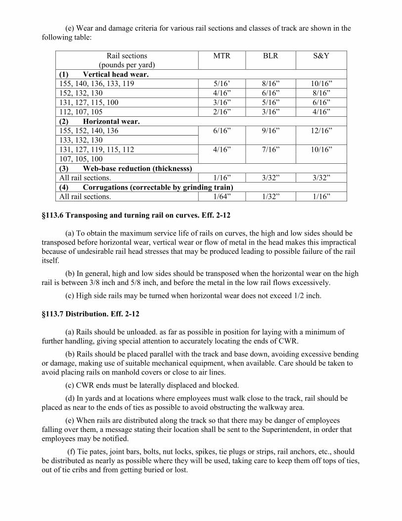
(e) Wear and damage criteria for various rail sections and classes of track are shown in the following table:
Rail sections (pounds per yard)
MTR BLR S&Y
(1) Vertical head wear. 155, 140, 136, 133, 119 5/16’ 8/16” 10/16” 152, 132, 130 4/16” 6/16” 8/16” 131, 127, 115, 100 3/16” 5/16” 6/16” 112, 107, 105 2/16” 3/16” 4/16” (2) Horizontal wear. 155, 152, 140, 136 6/16” 9/16” 12/16” 133, 132, 130 131, 127, 119, 115, 112 4/16” 7/16” 10/16” 107, 105, 100 (3) Web-base reduction (thicknesss) All rail sections. 1/16” 3/32” 3/32” (4) Corrugations (correctable by grinding train) All rail sections. 1/64” 1/32” 1/16”
§113.6 Transposing and turning rail on curves. Eff. 2-12
(a) To obtain the maximum service life of rails on curves, the high and low sides should be transposed before horizontal wear, vertical wear or flow of metal in the head makes this impractical because of undesirable rail head stresses that may be produced leading to possible failure of the rail itself.
(b) In general, high and low sides should be transposed when the horizontal wear on the high rail is between 3/8 inch and 5/8 inch, and before the metal in the low rail flows excessively.
(c) High side rails may be turned when horizontal wear does not exceed 1/2 inch. §113.7 Distribution. Eff. 2-12
(a) Rails should be unloaded. as far as possible in position for laying with a minimum of further handling, giving special attention to accurately locating the ends of CWR.
(b) Rails should be placed parallel with the track and base down, avoiding excessive bending or damage, making use of suitable mechanical equipment, when available. Care should be taken to avoid placing rails on manhold covers or close to air lines.
(c) CWR ends must be laterally displaced and blocked. (d) In yards and at locations where employees must walk close to the track, rail should be
placed as near to the ends of ties as possible to avoid obstructing the walkway area. (e) When rails are distributed along the track so that there may be danger of employees
falling over them, a message stating their location shall be sent to the Superintendent, in order that employees may be notified.
(f) Tie pates, joint bars, bolts, nut locks, spikes, tie plugs or strips, rail anchors, etc., should be distributed as nearly as possible where they will be used, taking care to keep them off tops of ties, out of tie cribs and from getting buried or lost.

§113.8 Preparation and care. Eff. 2-12
(a) As far as practicable, track should be placed in good line and surface prior to rail renewals. Track to be laid with CWR should be fully ballasted, and preferably, programmed tie renewals should be completed in advance of rail laying.
(b) Rails should be examined prior to laying in track to detect any sharp bends, damage or surface conditions that will make them unserviceable.
(c) Care of rail should be taken the day on which it is laid, so that no damage to rail or fastenings will result from continued use under normal traffic. Loose ties should be tamped to a good bearing under the rail immediately behind rail laying operations. §113.9 Laying jointed rails. Eff. 2-12
(a) Jointed rails should be laid, one at a time, with space allowance for expansion being provided between rail ends in accordance with the following table (next page):
33 ft. Rail 39 ft. to 160 ft Rails Rail temperature
(Deg. ºF.) Rail end space
(inches) Rail temperature
(Deg. ºF.) Rail end space
(inches) Below -10 -10 to 14 15 to 34 35 to 59 60 to 85 Over 85
5/16 ¼
3/16 1/8 1/16 None
Below 6 6 to 25 26 to 45 46 to 65 66 to 85 Over 85
5/16 ¼
3/16 1/8 1/16 None
(b) To insure the space allowance required, rail ends should be brought squarely together
against approved expansion shims of proper thickness and the rail joints bolted before spiking. (c) Space between rail ends in insulating joints should only be sufficient to permit insertion
of standard end posts. (d) A standard rail thermometer shall be used to determine the rail temperature. The
thermometer should be laid close to the web on the side of the rail base which is shaded from the sun's rays in advance of the laying operation and left there long enough to record the temperature accurately. The supervisory employee in charge shall see that rail temperature is checked frequently and that proper rail expansion shims are used. All thermometers must be checked by the Supervisor—Track to see that they are accurate.
(e) Except as otherwise provided, rails should be laid so that the joints of one line of rails shall be opposite the one third point of rails in the other line with permissible variations as follows:
(1) Except through turnouts and at insulated joints, the staggering of the joints on one side should not vary more than 30 inches in either direction from the one third point of the opposite rail, preferably not exceeding 18 inches.
(2) Rails laid with the joints of one line of rail opposite the middle of rails in the other line in accordance with former standards need not be relocated until out-of-face rail renewals are made.
(3) Where approved by the Division Engineer, joints on tangents in newly constructed track laid by the panel method, other than main track, may be left opposite, but joints on curves must be staggered in accordance with Paragraph (1), above.

(4) Where wreck panels have been installed in main tracks, protect by a maximum 30 MPH speed restriction until rails are staggered. (f) Rails less than 18 feet in length should not be used in main tracks, except that rails not
less than 14 feet may be used for: (1) Connections within turnouts and crossovers. (2) Temporary closures. (3) Temporary replacement of broken rails.
Rails not less than 14 feet in length used in accordance with previous standard practice need not be removed until rails are changed or relaid.
(g) When laying rail, placing bolted joints in or closer than 12 feet to the edges of road crossings, within the limits of switch rails or guard rails, or closer than 6 feet to the ends of open floor bridges, trestles or viaducts should be avoided, using long rails where necessary.
(h) Rails of the same sections should be used on open floor structures, through road crossings and paved track areas of station platforms, and to the greatest extent possible in turnouts and crossovers.
(i) Rails of unequal wear and different sections must be brought to an even surface at joints. If the difference in height of rails must be run off by the use of shims, wood or metal shims of proper thickness, with holes provided for spikes and of ample size to permit secure fastening to the ties, must be placed between the tie plates and the ties. When shimming is performed, the requirements of §213.129 must be met.
(j) The use of shims of spring washers between the web of the rail and the joint bar to aline the gage sides of rail heads or the use of acetylene torches or grinding to manufacture or change the dimensions of compromise joints is prohibited. Adjustments must be accomplished by:
(1) Compromise joints of approved design. (2) By grinding or welding rail head.
(k) When necessary to make a temporary connection for the passage of a train at normal speed, the connection must be made with a piece of rail not less than 14 feet long with compromise or standard joints with the full number of bolts and with all rail holding spikes driven. Use of switch points to make temporary connections when laying rail is prohibited.
§113.10 Bolt holes. Eff. 2-12 Holes for complete bolting must be provided at the ends of cut rails in accordance with standard arrangement and the following practice.
(a) When new holes are necessary, they must be drilled and not punched, shot, slotted or burned with a torch. All holes shall be of the full diameter and located in accordance with drilling instructions on the standard plan for the rail being drilled. They should be drilled with the joint bars removed or before their application, either by marking the location of the center of the hole, preferably with a proper size template block and center punch, and placing drill bit directly against the web of the rail, or by drilling through an approved template. New bolt holes should not be drilled through the joint bars.
(b) When bolt holes are drilled with a power track drill, a uniform feeding pressure should be maintained and then reduced as the bit point breaks through the opposite side of the web. A proper
lubricant should be used when drilling. Forcing the drill may produce a ragged hole, with possibility of resultant bolt hole cracks.
(c) After drilling is completed, bolt holes should be brushed out and inspected. Any burrs or chipped edges should be removed by grinding to a smooth edge around the entire circumference of the hole.
(d) The distance from the end of a rail to center of first bolt hole must not be less than twice the diameter of the hole, except where the standard plan for that rail provides for a lesser distance, this distance shall be minimum.
(e) The distance between centers of any two holes of the same diameter must not be less than four (4) times the diameter of the hole, and in the case of holes of different diameters not less than 3 3/4 times the average diameter of the two holes.
(f) The connection between rail ends should be made with fully bolted joint bars. (g) When it is necessary to use a cut rail at a compromise or insulated joint location, the mill or shop drilled end of the rail should be placed in the compromise or insulated joint. The bolt holes must be of full diameter and drilled before the joint is applied, and in accordance with provisions of paragraph (a) of this sub-section regardless of the weight of rail.
§113.11 Cutting rail. Eff. 2-12
(a) The tools which may be used for cutting rails are listed below: (1) Rail saws. (2) Track chisels. (3) Abrasive cutting wheels. (4) Gas cutting torches, in accordance with standard instructions, for yard tracks only.
All rails for use in other than yard tracks must be cut with a saw, if cropping is necessary. (b) When using a track chisel, a sledge must be used. The use of spiking mauls is prohibited. (c) Except for the welding of engine burns in accordance with approved methods, and except
for application of welded bonds, gas or electric arc welding is prohibited on any portion of the rail, except the top of the rail within the limits of joint bars.
(d) Any rail, in main track, other important track or in a track adjacent to a main or important track, which is accidentally damaged by tools used for cutting rail must be promptly removed from track. §113.12 Rails bonded for track circuits. Eff. 2-12
(a) Where rails are bonded for track circuits, no rail bonds shall be broken or rails removed, except in case of emergency, unless a signal maintainer is present to assure that the signals display their most restrictive indication and, in cab signal or train control territory, that coded track circuits are inoperative, and that facilities to bond the new rail are available. In case of emergency, a broken rail, switch or frog may be renewed without waiting for the signal maintainer. In such cases, the joints shall be tightened to make as good contact as possible with the rails, and the signal maintainer notified that the rail bonds have been broken. However, if such work is within the starting circuit of automatic highway crossing protection, the track shall not be restored to service until all trains approaching the crossing have been instructed to be prepared to stop prior to passing over the crossing involved, or until crossing protection is provided.

(b) In electric traction territory, care shall be exercised to insure that at least one return path for electric traction current is maintained, before disconnecting leads of impedance bonds or removing rails, frogs, etc. When making rail renewals, etc., before the rail is disconnected, a return path for current shall be provided by using a temporary bond across the track each side of the section of rail to be removed, making sure that no insulated rail joints interfere with this cross bonding circuit. In emergencies when the signal maintainer is not present, he shall be notified that the rail bonds have been broken. §119.0 Continuous welded rail (CWR). This section details RBMN’s policy on installing, adjusting, maintaining and inspecting Continuous Welded Rail (CWR) track. This plan details how RBMN applies its standards and procedures to comply with FRA standards. The following requirements apply to CWR on all main tracks and sidings. These requirements also apply to all tracks other than main tracks or sidings operation at speeds above class 1. 119.1 Installation Procedures Rail length that exceeds 400 feet is considered CWR. Rail installed as CWR remains CWR, regardless of whether a joint or plug is installed into the rail at a later time.
(a) Rail neutral temperature is the temperature at which a rail is neither in tension nor compression. Designated rail laying temperatures have been established to provide a high rail neutral temperature to prevent track buckling. When laying or adjusting CWR use the rail laying temperatures shown in Table 7-J.
(b)The difference between the designated rail laying temperature and the actual rail temperature taken at the time of installation is called the temperature differential. CWR laying and adjusting procedures have been established to compensate for this temperature difference.
(c) Follow these general requirements when installing CWR: (1) Take the rail temperature and calculate the expansion required before making
adjustments. (2) Record the rail laying temperature, location and date on approved forms. These
records may be retained in an electronic format per 213.241. (Refer to Record of Heat Control)
(3) Rail does not need to be adjusted when the actual rail temperature exceeds the designated rail laying temperature.
(4) Use rail heaters or rail expanders to adjust the rail to the correct length when the actual rail temperature is less htan the designated rail laying temperature. Heat the rail evenly and uniformly so that the rail expansion occurs evenly and uniformly throughout its length. If rail is laid at a temperature more than 40ºF below the designated rail laying temperature, rail must be adjusted or a speed restriction of 40 mph must be placed prior to rail temperature above designated rail laying temperature. When tight rail conditions exist, be governed by 119.7 (a)
119.2 Rail anchoring Where the anchoring function is otherwise provided, rail anchors may be omitted. Anchors may not be applied where they will interfere with signal or other track appliances, where they are

inaccessible for adjustment or inspection or on rail opposite a joint. Anchor pattern may be varied as reasonable to avoid placing anchors against deteriorated ties. Installation The following anchoring requirements apply to CWR installation on all main tracks and sidings. These anchoring requirements also apply to all tracks other than main tracks or sidings operating at speeds above class 1.
(a) When installing CWR, bos anchor every other tie except as outlined in (b). (b) When installing CWR, box anchor every effective tie at specific locations listed below to
provide additional restraint against rail.
Condition Action Turnouts Rail crossings Joints where CWR abuts jointed rail
Anchor every tie for 200’ in each direction
Bolted joint installed during CWR installation when using heater, rail stretcher or sufficient ambient temperature <<Effective January 01, 2010 >>
Within 60 days, weld joint, OR install joint with 6 bolts, OR anchor every tie for 200’ in each direction
(c) When installing CWR, follow these bridge anchoring requirements:
(1) Ballast deck bridges should be anchored with the same pattern as in (a) and (b). (2) Open deck bridges should be anchored according to (Standard Drawing 0461C.)
(d) On CWR installations completed before September 21, 1998, existing anchoring may remain if rail is restrained to prevent track buckles, but rail must be adjusted 9by increasing or decreasing the length of rail or by lining on curves) or anchors added to rail if restraint is not sufficient.
(e) when repairs result in a joint being added to CWR, the anchor pattern shall match the existing pattern in track. At least every other tie will be box anchored for a distance of 200 feet in each direction unless anchoring is otherwise provided or if it would conflict with Standard Drawing 0416C. when repairs are made to a stripped joint of failed joint bar, the adjustment or addition of anchors will be as prescribed in the following table:
Condition Action Bolted joint in CWR experiencing service failure (stripped joint) or failed bar(s) with gap* present *Gap exists if it cannot be closed by drift pin
1. Weld joint, OR 2. Remediate joint condisitons (per 119.6), replace bolts (new, in-kind or stronger), and weld joint within 30 days, OR 3. Replace failed bar(s), install 2 additional bolts and adjust anchors, OR 4. Replace failed bars, bolts (if broken or missing) and anchor every tie for 200’ in both directions, OR 5. Add rail

119.3 Preventative Maintenance Performing track buckling maintenance can reduce the risk of buckles. When tight rail conditions exist, be governed by 119.7.
(a) A record of rail neutral temperature will be maintained where rail has pulled apart, broken or been cut for defect removal. Record the length of the rail end gap and rail temperature in addition to the other required information on the Designated Rail Separation Form for determining rail neutral temperature. Rail that has pulled apart, broken or been cut for defect removal at rail temperatures at or below 60ºF must be readjusted to within the subdivision rail laying temperature minus 20º (RLT -20º) safe range. If the rail has not been readjusted to at least RLT -20º before rail temperatures exceed the values in the TABLE below, a speed restriction of 25 mph will be placed, or a speed restriction of 40 mph will be placed with a required daily inspection made during the heat of the day.
Rail beak or cut Temperature (ºF) Rail temperature (ºF) at which to readjust or apply slow order
60 135 50 130 40 125 30 120 20 115 10 110 0 105
-10 100 -20 95 -30 90 -40 85
Effective January 1, 2010, locations where the neutral temperature has been lowered below the safe zone by adding rail must be adjusted to RLT-20 F degrees or higher within 365 days of the date of the addition (broken rail/pull apart). If rail is added for any reason, measure and record the amount of rail added so that adjustments can be made if necessary. *This measurement may be made by the use of reference marks. The use of reference marks includes: -Marking the locations where rail is to be cut -Marking the rail outside the limits of the joint bars
-Measure the distance between the reference marks and mark it on the rail or otherwise record it
-Install the rail and re-measure the distance between reference marks -Record the difference and document the location Refer to Placing Rail Reference Marks Document When welding rail ends together, the required weld gap or rail consumption must be taken into consideration when determining the amount of rail adjustment. *Where rail has been added to re-establish the desired RLT this requirement need not apply.
(b) Rail can be de-stressed by cutting rail out or by re-aligning a curve. When cutting rail out, use this procedure:

(1) use a designated safe procedure to cut rail. It’s possible that the rail is under compression and may move unexpectedly. Cut rail to be de-stressed.
(2) Remove or reposition anchors or clips for a minimum of 200 feet in both directions from the cut or up to a restriction that prevents rail movement.
(3) Wait until the rails stop moving. The rail ends may need to be trimmed more than one time to allow for expansion.
(4) Take the rail temperature (5) If the actual rail temperature is lower by more than 20ºF form the designated rail laying temperature of the territory, use Table 4-H to determine the rail length to be removed based on the total distance the anchors or clops have been removed.
(6) If the rail temperature is at or above the designated rail laying temperature range (RLT-20), no additional adjustments are needed.
(7) Weld the joint or apply joint bars. (8) Replace the rail anchors or clips. 119.4 Monitoring Curve Movement
(a) Before surfacing and lining a curve on main tracks, stake curve if it is more than 3º and rail temperature is more than 50ºF below the designated rail laying temperature (or is forecasted to be in the next 24 hours). To stake a curve prior to surfacing and lining, place at least 3 reference points uniformly spaced around the curve. These reference point shall be no more than 200 feet apart.
(b) Inspect for curve movement periodically after the work, especially during periods of large temperature changes. Where curve has been staked per 119.4(a) and curve has shifted inward more than a maximum of 3 inches, the curve must be lined out. If curve is not lined out or de-stressed a speed restriction of 40 mph or less must be placed. When tight rail conditions exist, be governed by 119.7. 119.5Temporary Speed Restrictions Place a temporary speed restriction anytime the roadbed or ballast section is disturbed as reauried in 119.4(d), except where the maximum authorized speed of the track is equal to or less than the required restriction.
(a) Speed restrictions ensure safe train operations until the affected track stabilizes. Restrictions need to stay in place to allow the ballast to consolidate, rail compressive forces to equalize and the sub grade to compact. Take more restrictive measures when conditions warrant.
(b) During the work or before returning the track to service, the supervisor or foreman in charge must ensure that: (1) Gage, surface and alignment have been established (2) Crib and shoulder ballast is in place or lateral constraint is otherwise provided. (3) The rail is anchored per 119.2 or 119.3.
(c) To minimize running rail and other dynamic forces, trains must have time to brake and adjust slack before entering the disturbed track. For heavy grades, sharp curves or substandard track conditions, extend speed restrictions farther from the work limits, if needed.
(d) When the following track work has been performed, place a speed restriction that complies with the guideline below.

Activity Maximum Speed Minimum Duration
Out-of-face installation of ties Undercutting Laying track/switch panels Constructing track Out-of-face surfacing and lining
30 mph freight 40 mph passenger
8 freight trains or 16 passenger trains OR An equivalent combination*
Spot Maintenance -Installing ties (no more than 5 ties in 39 ft and no more than 3 consecutive ties) -Surfacing/lining (maimum length of 19’6”)
30 mph freight 40 mph passenger
1 train
Mechanically stabilized track performed after any of the activities listed above
30 mph freight 40 mph passenger
1 train
* 2 passenger trains are equivalent to 1 freight train
Activity Maximum Speed Minimum Duration Out-of-face installation of ties Out-of-face surfacing and lining Undercutting Laying track/switch panels Constructing track Exception: Spot maintenance does not require a speed restriction.
30 mph freight 40 mph passenger
1 train
Mechanically-stabilized track performed after any of the activities listed above
40 mph freight 1 train
When rail temperature is less than 80ºF, a speed restriction is not required. 119.6Rail Joint Inspections CWR Joint means any joint directly connected to CWR.
(a) All CWR joints within the following classes must be inspected on foot: (1) Class 2 on which passenger trains operate, and (2) Class 3 and higher
(b) CWR joints shall be inspected on foot at the following minimum frequencies:

Minimum Number of Inspections Per Calendar Year1 Freight Trains operating over track with an
annual tonnage of: Passenger Trains operating over track with an annual tonnage of:
Less than 40 mgt
40 to 60 mgt Greater than 60 mgt
Less than 20 mgt
Greater than or equal to 20 mgt
Class 5 & above
2x 3x2 4x2 3x2 3x2
Class 4 2x 3x2 4x2 2x 3x2
Class 3 1x 2x 2x 2x 2x Class 2 0 0 0 1x 1x Class 1 0 0 0 0 0 Excepted Track
0 0 0 n/a n/a
4x = Four times per calendar year, with one inspection in each of the following periods: January to March, April to June, July to September, and October to December; and with consecutive inspections separated by at least 60 calendar days. 3x = Three times per calendar year, with on inspection in each of the following periods: January to April, May to August, and September to December; and with consecutive inspections separated by at least 90 calendar days. 2x= Twice per calendar year, with one inspection in each of the following periods: January to June and July to December; and with consecutive inspections separated by at least 120 calendar days. 1x= once per calendar year, with consecutive inspections separated by at least 180 calendar days 1Where a track owner operates both freight and passenger trains over a given segment of track, and there are two different possible inspection interval requirements, the more frequent inspection interval applies. 2When extreme weather conditions prevent a track owner from conduction an inspection of a particular territory within the required interval, the track owner may extend the interval by up to 30 calendar days from the last day that the extreme weather condition prevented the required inspection.
(c) Each CWR joint requiring action as outlined in 119.6(e) shall be identified in the field with a highly visible marking. In addition, such joints shall also be identified as to location by specifying the subdivision, milepost, track number and rail (north, south, etc.)
(d) Joints within or adjacent to switches, track crossings, lift rail assemblies or other transition devices on moveable bridges are exempt from the periodic join inspection requirements provided they are inspected monthly during the required monthly walking inspection of these devices. Therefore, inspect these locations on a minimum monthly basis and include in the inspection and report on the following: At switches:
(1) All joints from and including the insulated joints at the signals governing movement entering and leaving the control point or interlocking
(2) If there are no signals at the switch location, include as a minimum all joints from the point of the switch to the heel of the frog.
At cross-overs:

(1) All joints in track between switches. At track crossings:
(1) All joints form and including the insulated joints at the signals governing movement entering and leaving the control point or interlocking.
(2) If there are no signals at the track crossings, include as a minimum all joints that are between or connected to the crossing frogs.
At lift rail assembles or other transition devices on movable bridges: (1) All joints immediately attached to the rail assembly or transition device.
Should a cracked or broken join bar be discovered during the monthly inspection of any of the above locations, a Fracture Report must be completed as per 119.6(g). (e) When inspecting CWR joints on foot in track listed in 119.6(a), inspector must watch for
(but not be limited to) the following rail joint conditions outlined in the table below. When such conditions are found, the appropriate action must be taken as outlined. Rail joint condition Action1 Visible cracks in joint bar Replace bar Loose bolts Tighten bolts Bent bolts Replace bolts OR Reinspect as per 119.6(b) Missing bolts2 Replace bolts Tie(s) not effectively supporting joint Tamp tie(s)
Replace or repair tie(s) OR Conduct follow-up inspections every other week until repaired/removed
Broken or missing tie plate(w) Replate tie plates(s) OR Conduct follow-up inspections every other week until repaired/removed
Deteriorated insulated joint Replace/repair joint OR Conduct follow-up inspections every other week until repaired/removed
Rail end batter (More than 3/8” in depth and more than 6” in length measured with a 24 “straight-edge)
Repair by welding joint or removing rail OR Conduct follow-up inspections every other week until repaired/removed
Rail end mismatch reaches limits specified by 49 CFR 213.115
Weld or grind
Longitudinal rail movement greater than 2: Add or adjust rail anchors, tighten bolts, add or remove rail at appropriate time.
Wide rail gap greater than 1.5” Adjust rail gap and secure joint OR Conduct follow-up inspections every other week until repaired/removed
Joint vertical movement (profile) that exceeds 75% of the allowable threshold for the designated class of track3
Surface join OR Conduct follow-up inspections every other week until repaired/removed
Joint lateral movement (in a curve or spiral) that reaches ¾”3
Correct lateral movement OR Conduct follow-up inspections every other week until repaired/removed

1 Action may also consist of placing a speed restriction or removing the track from service
2 A minimum of 2 bolts per rail must be in place at each joint 3 Joint lateral and vertical movement is the apparent visible movement measured at the
joint
(f) Embedded Joints (1) Permanently Embedded Locations Where such locations exist, it is not necessary to disassemble or remove the track
structure (e.g., remove pavement or crossing pads) to conduct an inspection of CWR joints. Make every effort, to the extent practicable, to inspect the visible portion of joints in these structures.
(2) Temporarily Buried Locations Joints may sometimes be temporarily buried 9e.g., where ballast or similar material is
in the middle of the track and along the track) and therefore unavailable for inspection. Where CWR joints are buried (e.g., by ballast), wait for the completion of the track work before conducting joint bar inspections. (g) Inspection Records
(1) On-Foot Periodic and follow-up Inspection Reports Document each on-foot periodic and follow-up inspection on the date of the
inspection by noting the following information (i) Date (ii) Limits of the inspection (iii) Location and nature of CWR joint conditions specified in 119.6(e) (iv) Corrective or Remedial action (v) Name and signature of inspector
(2) Fracture Reports Track subject to inspections under 213.119(H)(6)(i), must have a Fracture Report
completed for every cracked or broken CWR joint bar that is discovered during the course of an inspection conducted to comply with:
(i) Track Inspections (213.233) (ii) Inspections of switches, turnouts, track crossings, lift rail assemblies or
other transition devices on moveable bridges (213.235). (iii) Periodic and Follow-Up CWR Joint Inspections (213.119(g))
The Fracture Report shall be prepared on the date the cracked or broken joint bar is discovered. Refer to Fracture Report Form 119.7Extreme Weather Inspections For purposes of forecasting or initiating extreme weather inspections and conversions of rail temperature in relation to ambient temperatures use the following conversions: -In hot weather rail temperature is equal to ambient temperature plus 30ºF. -In cold weather rail temperature is equal to ambient temperature

(a) On main tracks hot weather inspections must be performed as directed. Perform inspections during the heat of the day – primarily between 12 noon and 6 pm. Inspector will inspect for signs of tight rail conditions, including:
(1) Kinky or wavy rail (2) Rail canting or lifting out of tie plates (3) Shiny marks on the base of the rail indicating that the rail is running through
anchors and spikes (4) Gaps in ballast at the ends of ties (5) Churning ballast and ties
When tight rail conditions are present such as above, a speed restriction of 25 mph or less must be placed or track removal from service until repair or adjustment is made. Inspectors will pay special attention to the following locations:
(1) Recently disturbed track (2) Track at the bottom of sags (3) Locations where heavy braking occurs (4) fixed track structures, such as turnouts and bridges (5) Locations where rail has been repaired or welds made
(b) On main tracks, cold weather inspections must be performed as directed or when the rail temperature is forecast to drop 100ºF below the rail laying temperature. Inspectors will inspect for:
(1) Broken rails (2) Pull-aparts (3) Wide gap between rail-ends (4) Cracked or broken joint bars (conventional and insulated) (5) Bent bolts (6) Curve movement (7) Canted rail
119.8 Training All employees responsible for the inspection, installation, adjustment or maintenance of CWR track must complete training on CWR procedures every calendar year. In addition, they shall be provided a copy of these procedures and accompanying documents. Engineering Director and Managers will maintain lists of those employees qualified to supervise restorations and inspect track in CWR territory. The qualified employee lists will be made available to the FRA upon request. Training programs will address the following:
(a) CWR installation procedures (b) Rail anchoring requirements when installing CWR (c) Preventative maintenance on existing CWR track (d) Monitoring curve movement following track surfacing and lining

(e) Placing temporary speed restrictions on account of track work (f) Rail joint inspections (g) Insufficient ballast (h) Extreme weather inspections (i) Record keeping
119.9 Recordkeeping
(a) Rail temperature, location and date of CWR installations must be recorded on the prescribed form and must be retained for at least one year after installation. Refer to Record of Heat Control
(b) Because track maintenance can disturb the lateral and longitudinal resistance of the track, records of the following must be kept until corrections or adjustments are made:
(1) Rail that is added for any reason, including repair of broken or defective rail, pull-aparts and welding of rail joints.
(2) Where curve has been staked and has shifted inward more than a maximum of 3 inches
(3) CWR installation or maintenance work that does not conform to these written procedures.
(4) A record of rail neutral temperature will be maintained where rail has pulled apart, broken or been cut for defect removal
Track Maintenance Supervisors must monitor these records to ensure necessary corrections and adjustments are made. 119.10 Tables/Diagrams See appendices at end of manual §121.2 Bolted rail joints. Eff. 2-12
(a) General. (1) Bolted rail joints consist of either head free or head contact standard bars and
compromise joint bars held in position by track bolts having sufficient tension to firmly support abutting rail ends, but not too tight to prevent longitudinal movement in joints to accommodate expansion and contraction due to variation in rail temperature.
(2) Head free bars must have the inner surface of the head of the bar held tightly against the rail head fillet with the heel of the bar standing out the proper distance from the base fillet, where all of the "draw-in" for wear is concentrated.
(3) Head contact bars must have the top surface of the bar held tightly against the fishing surface under the rail head outside of the rail head fillet area. Bars must be secured in a vertical position without "cocking"

(b) Application. (1) Joint bars shall be applied with their full number of bolts, nuts and spring washers
according to standard plans and specifications. (2) New bolts, nuts and spring washers should be used when new or reformed joint
bars are applied or renewed out-of-face. (3) When initially applying joint bars, the bolt tension should be brought in the range
of 20,000 to 25,000 pounds, and for subsequent retightening from 15.000 pounds to 20,000 pounds. This may be approximated by an average man with a 36 inch track wrench. (c) Head free joints.
The following procedure should be followed in applying head free joint bars: (1) Set bars in position, insert all bolts and apply spring washers and nuts by hand. (2) Run up the No. 3 and No. 4 nuts with a power track wrench in high gear, without
fully tightening to avoid locking the bars in an improper position. Strike the bead on the heads of both inside and outside bars at both ends with a hammer to force the inside faces of bars tightly against rail head fillets. Do not strike the toe of the bar as this tends to force the head of the bar outward. Tighten remainder of bolts from center of joint bars outward in high gear.
(3) Tighten all bolts in low gear, working from center of joint bars outward. During this final tightening, drive the toes of the bars inward by tapping with a spike maul or sledge. By following the above procedure, proper contact will be obtained between inner face of head of bar and the rail head fillet. Also, the heel of the bar will stand out the proper distance from the rail base fillet. (d) Head contact joints. The following procedure should be followed in applying head
contact joint bars: (1) Set bars in position on rail, insert all the bolts and apply spring washers and nuts
by hand. (2) See that bars are in a vertical (uncocked) position as one of the center bolts in
tightened by: (i) Inserting a bar in a bolt hole.* (ii)Tapping toes of joint bars as bolt is tightened.
*Necessary when applying 131 lb. or 152 lb. joint bars only. (3) Tighten all bolts in low gear, working from center of joint bars towards ends,
tapping the toes of joint bars with a spike maul or sledge so that their vertical position is maintained. (e) Maintenance.
(1) Drilled ends of new rails are ground to remove burrs at the mills. (2) To avoid chipping or spalling under service due to overflow of steel, the rail end
faces should be cross cut by grinding with a 1/8 inch wheel to a depth of 3/16 inch below the surface of the head. The maximum cut should not be wider than 1/8 inch. If the rails are not in contact, the overflowed metal should be removed from both end faces.

(3) When bolted joints are applied, other than insulated joints, the bolts should be tightened at the time they are applied, retightened within a week and again within a month after application.
(4) Bolts should be retightened periodically at intervals of not more than one year. and in all cases following program track raising or surfacing.
(5) To prevent undue rail stress on account of expansion or contraction at the changes of seasons and wide temperature changes, sufficient joint bars should be loosened to permit the rail to adjust themselves, immediately after which bolts should be retightened. Where necessary, a piece of rail should be cut out to avoid heat kinks or buckling of the track.
(6) Wear in the fishing spaces of rail should be compensated by the application of oversize joint bars.
§122.0 Insulated rail joints. §122.1 Stagger of insulated joints. Eff. 2-12
(a) At automatic signal locations outside of interlocking limits in non-cab signal territory, non-electrified territory, and territory where stray currents are not prevalent the stagger shall not be more than 120 inches nor less than 60 inches.
(b) At automatic signal locations in cab signal territory, electrified territory and territory where stray currents are prevalent the stagger shall not be more than 64 inches nor less than 60 inches.
(c) Within non-interlocked or interlocked crossovers or turnouts the stagger shall not be more than 60 inches nor less than 30 inches.
(d) At power operated sliding or switch point derails the stagger shall not be more than 64 inches nor less than 60 inches.
(e) At hand operated sliding or switch point derails the stagger shall not be more than 240 inches nor less than 66 inches.
(f) At highway crossings, cut sections and other locations where track circuits adjoin the stagger shall not be more than 120 inches nor less than 66 inches.
(g) At the end of a track circuit where there is no adjoining track circuit existing joints may be used but the stagger shall not be more than 39 feet nor less than 19 feet 6 inches.
(h) Reference MW Standard Plan 71325-( ) for stagger of insulated joints. §122.2 Location of insulated joints. Eff. 2-12
(a) At new locations of automatic signals both joints must be in advance of the signal but not to exceed 28 feet in advance of the signal except where opposing signals are mounted on the same mast, or when opposing signals are on opposite sides of the same track, the insulated joints must be on opposite sides of the center line of the signal.
(b) When making use of existing joints at automatic signals the preferred location of the insulated joints is in advance of the signal but not to exceed 28 feet to the rear or advance of the signal.

(c) At interlocked crossovers or turnouts the effective insulated joint shall be located 22 feet ahead of the point of switch and shall not be more than 13 feet nor less than 0 feet in advance of the signal.
(d) At power operated sliding or switch point derails the effective joint shall not be more than 5 feet from the derail and shall not be more than 13 feet nor less than 0 feet in advance of the dwarf signal. The derail shall be located not less than 15 feet from the clearance point.
(e) At power operated turnouts where the movement from the side track is controlled by a dwarf signal the effective insulated joint shall not be less than 15 feet from the clearance point and shall not be more than 13 feet nor less than 0 feet in advance of the dwarf signal.
(f) At hand operated sliding or switch point derails one insulated joint shall not be more than 5 feet from the derail. The derail shall be located not less than 15 feet from the clearance point. (g) Insulated joints at highway grade crossings shall be located in accordance with Signal Plans.
(h) Insulated joints located in accordance with former Carrier's previous specifications need not be relocated until the rail is renewed or to comply with U.S. Department of Transportation Rules, Standards and Instructions.
(i) Reference MW Standard Plan 71325-( ) for location at insulated joints. §122.3 Application of continuous insulated joints. Eff. 2-12
(a) An insulated joint should not be applied to rails with battered or rough cut edges as they will damage insulating parts. Such edges which come in contact with the insulating parts of the joint, i.e., under the rail head, web and top and bottom of the rail base should be rounded to approximately 1/8 inch radius by grinding or filing.
(b) Rails should be spaced so the ends will bear firmly against end post to avoid damage to bolts and bushing. If the opening between rail ends is too small, the rail ends should be forced apart with an approved rail expander. Use of a track chisel or wedge may leave rough edges that will destroy the insulating material. The end posts should not project above or beyond rail heads. The portion projecting above the rail should be removed by cutting.
(c) Ties, preferably three under each continuous type insulated joint 36 inches or more in length, should be spaced and tamped to provide uniform support. Parkway outlets ("boot legs") should be moved if they will interfere with arranging ties accordingly.
(d) Abrasion plates must be used under continuous insulated joints, Standard Plan 72091-( ). (e) Before insulated joints are applied, the parts of the rails to be covered by the insulated
joint should be thoroughly cleaned to remove all rust, scale and dirt. All metal parts of the joint should be thoroughly cleaned.
(f) First insert the end post. Then apply the insulating base plates and metal joint bars to each side of the rails and drive them on the rails with a sledge or hammer, striking only the lower edge of the bars until there is just enough room left to insert the head pieces. After the head pieces are in place, insert bushings in bolt holes, and apply the insulating washer plates and metal washer plates with the bolts and nuts. Joint bars should be drawn into position by alternately driving with a sledge or hammer along the base of one bar and tightening the nuts by hand wrenches, beginning with the two center bolts and progressing to the end bolts, and then proceeding in the same manner on the other joint bar. This procedure must be followed to avoid "cocking" the bars. Do not drive the heads of the bars. They will be drawn into place by bolt pressure. Bolts in continuous insulated joints must be kept sufficiently tight at all times to prevent movement of the rail in the joint.

(g) A bolt should never be driven through an insulated bushing, as it will destroy the bushing. If rails and joint parts are in correct relative position, and the bolt holes lined up, the bolts can easily be inserted by hand. §122.4 Application of bonded insulated joints. Eff. 2-12
(a) Bonded insulated joints should be used in CWR track. (b) Rails connected by bonded insulated joints must be field welded in place. (c) All bonded insulated joints are to be installed as suspended joints. (d) Double shoulder tie plates must be used on the two ties under bonded insulated joints. (e) Rail holding spikes must be reversed and carefully hand driven to assure that spike head
is not left in contact with the bar which could result in the joint being short circuited. All bonded insulated joints will have plate holding spikes installed.
(f) No attempt should be made to tighten bolts in bonded insulated joints. In the event the bolts in the joint become loose, the Division Engineer should be notified for further handling.
(g) No additional rail anchors will be required at bonded insulated joint locations in CWR. The bonded insulated joints will be considered as butt welded rail joints for purposes of compliance with the requirements of §213.120(d). §122.5 Care of joints. Eff. 2-12
(a) Insulating joints should be supported on sound smooth ties, well tamped and well drained with clean ballast at all times.
(b) Continuous insulated joints require more frequent and careful attention than conventional joints. Bolts should be tightened within three days and again within a month after joints are applied. While tightening, bars and bolt heads should be tapped with a hammer to insure proper contact in fishing spaces.
(c) At continuous insulated joint locations where rail end welding is required, the insulated joint should be removed, standard bars applied and joint surfaced before welding.
(d) Any rail head overflow at a bonded insulated joint is to be removed by the use of a hand file or hacksaw. Extreme care must be exercised to assure that the end post is not damaged. The overflow should be removed only to the rail end, so that the joint gap will not be greater than the original 3/16 inch. A cross grinder should not be used to remove the overflow.
(e) At bonded insulated joint locations where rail end welding is required, welding should be done in accordance with approved procedures. §123.0 Tie plates. §123.1 Use. Eff. 2-12
(a) Tie plates shall be used under running rails on cross ties. switch ties and bridge ties and as specified in §213.123.
(b) Canted tie plates replacing level tie plates should only be applied in out-of-face stretches. (c) Only double shoulder tie plates should be used under CWR.

§123.2 Placement. Eff. 2-12
(a) Care must be taken that the shoulders of single shoulder tie plates and the outside shoulders of repunched double shoulder tie plates will have full bearing against the base of rail and be centered on the tie.
(b) Tie plates having shoulders must be placed so that no part of the shoulder is under the base of the rail. §123.3 Tie pads. Eff. 2-12 Tie pads shall be used on bridge ties in accordance with Standard Plan 79401-( ). §125.0 Rail anchors. §125.1 Number required. Eff. 2-12
(a) A sufficient number of anchors must be applied and in a manner to effectively control longitudinal rail movement, as required by §213.125(a).
(b) The number of rail anchors required to control longitudinal rail movement for a given location can be fixed only by experience and judgment, and is to be determined by the Supervisor-Track with approval of the Division Engineer. Insufficient anchors may result in improper distribution of expansion allowance, or stresses in CWR, and consequent distortion of line and surface, which can create a hazardous condition.
(c) Additional anchors must be applied when there is evidence that rails are moving progressively under traffic.
(d) It should be recognized that when track is raised out-of-face, the resistance to creepage is reduced and additional anchors may be required in order to avoid undue movement.
(e) In general. main line high-speed main tracks require eight (8) anchors per 39 feet of rail applied against movement in the normal direction of traffic. Additional anchors against reverse movement may also be required. For tracks of lesser traffic, including main tracks or branch lines, from 4 to 6 anchors per 39 feet of rail or even less may be sufficient.
(f) On single track, or on other tracks having traffic in both directions, a sufficient number of anchors shall be applied in each direction to stabilize the rails and, in addition to preventing progressive movement in one direction, to prevent backward and forward movement of ties and resultant disturbance of tamping. gg) When anchoring rails greater than 39 feet and up to 160 feet in length, additional anchors are required because of the relative reduction in the expansion allowance per foot of track. A minimum of 24 anchors per 78 feet of rail in the normal direction of traffic (more or less in proportion for other lengths) with one-fourth (1/4) of the anchored ties boxed for reverse anchoring is needed in order to restrain the tendency of such track to gain expansion.
(h) The number of anchors to be applied when CWR is laid and subsequently maintained is prescribed in §213.120(d).
i) Additional anchors as needed shall be applied on the approach and leaving rails: (1) To main track turnouts and crossovers. (2) To track crossings. (3) To highway grade crossings. (4) To open floor bridges.

(5) To insulated joints. (6) At hot box detectors.
(j) Rail anchors on bolted rail or CWR shall not be used on open deck bridges, trestles or viaducts, except where the deck and bridge meet the requirements of §119.1(b), or their use is approved by the Chief Engineer M.W. §125.2 Application. Eff. 2-12 Rail anchors shall be applied as follows:
(a) Anchors shall be applied at both ends and on the same side of the tie. They should be spaced throughout e rail length as evenly as practicable, except at those locations where on account of tests, special authorization or conditions, etc., other spacing may be desirable. Wherever practicable, rail anchors shall be applied from the gage side of the rail.
(b) When laying rail, the necessary anchors shall be applied before trains are permitted to pass over the track.
(c) Anchors should be applied against sound ties. (d) There is no restriction on the placement of rail anchors adjacent to plant or field welds,
providing the anchor does not contact the weld. At locations where anchors are omitted due to welds, the anchor on the opposite rail should be omitted.
(e) Where anchoring for both directions of traffic is required, reverse anchors should be applied to ties already having anchors in the normal direction. In other words, the practice of boxing the tie, and not the tie crib, must be followed. §125.3 Maintenance. Eff. 2-12
(a) Rail anchors must have full bearing against the tie or tie plate when applied. (b) In order to avoid damage to rail anchors, only proper tools or machines should be used in
applying and removing. Anchors may be moved along the base of the rail with an approved device, but should not be driven along the base with a hammer.
(c) When the bearing of rail anchors against the tie is disturbed, when renewing or respacing ties or moving rail, the anchors must be mechanically shifted or taken off and then reapplied in proper position. All anchors removed must be reapplied before track is restored to service, replacing any broken or defective anchors and adding additional anchors, if necessary.
(d) Proper opening between rail ends is provided and maintained by the use of adequate rail anchors. Where rail openings are excessive, the rails should be driven back to provide uniform space allowance for expansion, necessary rails of suitable length inserted, and an adequate number of rail anchors applied to hold the rails against running in either direction. Where insufficient expansion allowance has developed so that line kinks can result in hot weather, similar adjustment should be made in order to increase the allowance, inserting shorter rails of suitable length where necessary, again applying sufficient anchors to control creepage. §125.4 Assignment. Eff. 2-12 The use of rail anchors should be in accordance with the following service assignment:
(a) Use new anchors in laying:

(1) New bolted rail. (2) New or fit continuous welded rail.
(b) Use fit anchors if available in: (1) Laying bolted fit rail. (2) Applying additional or replacement anchors.
§127.0 Spiking. §127.1 Number required. Eff. 2-12
(a) The requirements of §213.127 must be satisfied except in those areas where existing tie plates under "toed" (skirted) joint bars are not punched to permit spiking of the joint bars.
(b) Additional spikes may be used where, in the judgment of the Supervisor—Track, they are needed to hold gage.
(c) Plate holding spikes shall be driven with the head pointed toward the rail. §127.2 Application. Eff. 2-12
(a) Spiking arrangement for tie plates shall be in accordance with Standard Plan 72051-( ). (b) Spikes must be started vertically and square, and driven straight. The shank of rail
holding spikes must have full bearing against the base of rail. Spikes should be kept driven home, being careful not to overdrive.
(c) Care must be taken not to strike the rail, its fastenings or signal appliances when driving spikes.
(d) Spikes in main tracks when badly throat cut or rusted should be replaced. (e)All old spikes shall be sorted when pulled for reuse or scrapping.
§132.0 Track crossings. §132.1 Use Eff. 2-12
(a) Crossings of manganese steel or bolted heat treated rail construction shall be used as approved by the Chief Engineer M.W. at intersections where there is heavy or high speed traffic on either run.
(b) Non-heat treated bolted rail crossings should only be used where traffic is light or in emergency. §132.2 Installation. Eff. 2-12
(a) When handling or placing, care should be taken to avoid damage to crossing frogs, using a crane where practicable. Whenever it becomes necessary to use jacks on crossing frogs, they should be set under the frog proper, and not under the arms.
(b) Crossings should be installed on sound treated timbers or framed foundations, located to permit satisfactory tamping.

(c) An ample bed of clean ballast over a geotextile fabric should be provided along with good drainage. §132.3 Maintenance. Eff. 2-12
(a) Rigid, slip and movable point crossings should be maintained to the alinement and to the ordinates from the diagonal shown on manufacturer's plans.
(b) Lipped metal should be removed from crossing frogs by grinding in accordance with standard instructions.
(c) Bolts must be kept tight and broken bolts renewed promptly. (d) Ballast should be kept well tamped so that the surface of the frog is maintained at a
uniform grade with the adjacent track. (e) Crossing frogs may be built up in the field by the electric arc method in accordance with
standard instructions. Ground clamps employed for welding must be applied to the rail or piece of steel being welded as reasonably close to the work as possible.
(f) The requirements of §213.53 and §213.143 must be met in maintaining proper track gage, guard face gage, and "back to back" distance through track crossings.
(g) The requirements of §123.133 and §213.137 must be met in maintaining track crossings in their proper condition. 133.0 Turnouts and crossovers. §133.1 Use. Eff. 2-12 Turnouts and crossovers are designated by their frog numbers and should be used as follows:
(a) No. 20—At interlocking plants for crossing over of high speed trains from one main track to another main track normally used in the same or reverse direction, in locations where the normal speed is 50 miles per hour or more.
(b) No. 15—At interlocking plants for movements to another main track normally used in the same or reverse direction, where conditions do not justify or afford the distance required for No. 20 frogs. For diverting trains to sidings or other tracks and returning trains to main tracks through power operated or spring switches.
(c) No. 10—For all other turnouts from main tracks and sidings where practicable, and in yards and terminals where road locomotives operate.
(d) No. 8—For turnouts where the use of a No. 10 frog is not practicable. (e) Turnouts smaller than No. 8 must have approval of the Chief Engineer M.W.
133.2 Speeds through turnouts. Eff. 2-12
(a) The maximum permissible speeds through level turnouts, when located in tangent track will be as follows:

Frog No.
Switch Point Length Permissible Speed – MPH
20 20 15 10 8 6
39 ft. or 45 ft. 30 ft. 26 ft. or 30 ft. 16 ½ ft., 18 ft. or 20 ft. 16 ½ ft., 18 ft. or 20 ft. 10 ft. or 11 ft.
40 35 30 15 15 5
(b) When turnouts or crossovers are located in curved tracks, speed must be adjusted to agree
with the table in §213.57(d). §133.3 Installation. Eff. 2-12
(a) Turnouts and crossovers constructed in track or at the site shall be built to and conform to Standard Plans.
(b) An ample bed of clean ballast over a geotextile fabric should be provided along with good drainage.
(c) Prefabricated turnouts shipped in panels in accordance with approved plans may be used where economical.
(d) As far as practicable, when being constructed or renewed in existing main tracks, turnouts should be completely installed with switches connected to their operating mechanisms and properly adjusted before trains are permitted to move over the turnout.
(e) Where only one switch point (closed point) has been installed in a turnout under construction or renewal in existing main track, and it is necessary to move trains over the turnout on the main track, the following precautions must be taken:
(1) All switch plates on the turnout side must be fully spiked in correct position. (2) The main track switch point must be securely held against its stock rail by driving
a spike in each of the first two ties back of the point, and where possible, spikes must pass through holes in the switch plates.
(3) The free end of stock rail must be fastened to prevent movement. (4) Facing train movements shall be made only under 10 MPH speed restriction.
(f) Where both switch points have been installed, but not properly connected to the switch operating mechanism, the following must be done before trains are permitted to move on the main track over the turnout:
(1) Switch rods must be installed. (2) The main track switch point must be spiked against its stock rail as required by
paragraph (d)(2) above. (3) The diverting switch point (open point) must be blocked by driving a wooden
wedge, not less than 18 inches long, between the switch point and its stock rail. The wedges must be secured in place by means of: a lag screw or heavy nail through one clip bolt hole; a piece of wood placed against the end of the wedge and spiked to the first and second ties ahead of the point; or a light flat headed bolt through a hole in the wedge adjacent to the side of the first tie under the switch point and between this tie and the No. 1 or head rod, with the bolt secured in place by a cotter pin or split key below the bottom of the wedge.
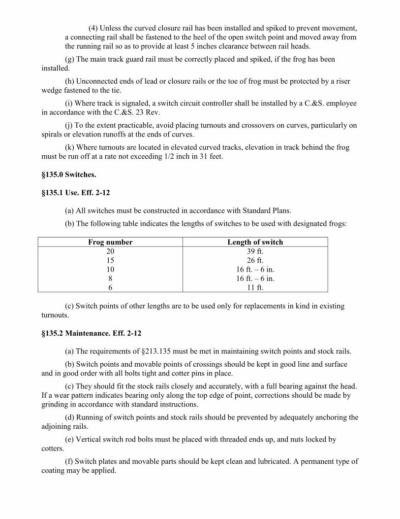
(4) Unless the curved closure rail has been installed and spiked to prevent movement, a connecting rail shall be fastened to the heel of the open switch point and moved away from the running rail so as to provide at least 5 inches clearance between rail heads. (g) The main track guard rail must be correctly placed and spiked, if the frog has been
installed. (h) Unconnected ends of lead or closure rails or the toe of frog must be protected by a riser
wedge fastened to the tie. (i) Where track is signaled, a switch circuit controller shall be installed by a C.&S. employee
in accordance with the C.&S. 23 Rev. (j) To the extent practicable, avoid placing turnouts and crossovers on curves, particularly on
spirals or elevation runoffs at the ends of curves. (k) Where turnouts are located in elevated curved tracks, elevation in track behind the frog
must be run off at a rate not exceeding 1/2 inch in 31 feet. §135.0 Switches. §135.1 Use. Eff. 2-12
(a) All switches must be constructed in accordance with Standard Plans. (b) The following table indicates the lengths of switches to be used with designated frogs:
Frog number Length of switch
20 15 10 8 6
39 ft. 26 ft.
16 ft. – 6 in. 16 ft. – 6 in.
11 ft.
(c) Switch points of other lengths are to be used only for replacements in kind in existing turnouts. §135.2 Maintenance. Eff. 2-12
(a) The requirements of §213.135 must be met in maintaining switch points and stock rails. (b) Switch points and movable points of crossings should be kept in good line and surface
and in good order with all bolts tight and cotter pins in place. (c) They should fit the stock rails closely and accurately, with a full bearing against the head.
If a wear pattern indicates bearing only along the top edge of point, corrections should be made by grinding in accordance with standard instructions.
(d) Running of switch points and stock rails should be prevented by adequately anchoring the adjoining rails.
(e) Vertical switch rod bolts must be placed with threaded ends up, and nuts locked by cotters.
(f) Switch plates and movable parts should be kept clean and lubricated. A permanent type of coating may be applied.

(g) Switch point repair by welding is permitted in yard tracks only. (h) Switch point but not including movable point rail of crossing, shall be replaced when
raised portion of switch point is worn down to the level of the top of the stock rail. §135.3 Reduction in wear. Eff. 2-12
(a) In main tracks without restriction: (1) Use of heat treated switch points. (2) Use of "Samson" design switch points with undercut stock rails. (3) One-quarter ( 1/4) inch maximum depth recess in the gage sick of stock rail, in
accordance with standard instructions, with conventional switch points. Recesses must not be cut for switch points unless they are equipped with heel blocks. (b) In main tracks, yards and terminals where the maximum authorized speed does not
exceed 15 mph: (1) Switch point guard of approved manufacture applied to the outside of stock rail
with approval of Chief Engineer M.W. (2) Reverse bend (goose neck) in the stock rail to house the switch point. Switch
points must be equipped with heel blocks. §135.4 Protection. Eff. 2-12
(a) When necessary to disconnect a switch, movable point crossing or a derail from its operating mechanism, or to disconnect the No. 1 switch rod, the following precautions must be taken:
(1) The closed switch point or movable point rail must be spiked against the stock rail as required by §133.3(d)(2).
(2) The switch must be blocked in position by driving a wooden wedge, as required by §133.3(e)(3), between the open switch or movable point rail and the stock rail or knuckle rail.
(3) If a switch, movable point crossing or derail is in track circuit territory, or if its position controls the indication displayed by a signal, the work of disconnecting switch rods must be done in charge of the Foreman-Track in cooperation with the Signal Maintainer. (b) Where both No. 1 and No. 2 switch rods are to be disconnected, train movements shall
not be made over the switch until one or both rods are properly connected to the switch points or movable point rails and the switch or movable point crossing is secured and protected as required by paragraph (a) above.
(c) If the open switch point is removed, trains may be moved over the turnout under the following conditions:
(1) Trailing movements may be made after closed switch point is spiked as required by §133.3(d)(2).
(2) For facing movements, in addition to properly spiking the closed switch point in accordance with §133.3(d)(2), the near end of the closure rail must be moved away from the running rail to provide at least 5 inches clearance between rail heads and be protected by a riser wedge fastened to the tie. Train movements shall be made only under 10 MPH speed restriction.

§135.5 Inspection. Eff. 2-12
(a) Switch points and parts, and connections, must be examined frequently. It is important that the stock rails have no lateral movement in the switch plates and that switch plates have no movement on the ties. Monthly inspections shall be made as required by Form MW 41 and necessary adjustments made at once. Annual inspections are to be made and recorded on Form MW 43.
(b) Chipping or unusual wear on any switch point should be investigated, its cause determined and corrective action taken. When wear or chipping has produced a sloping top surface which may tend to raise a wheel having an imperfect flange, the switch point should be further examined to locate any point of hard contact, which would necessitate repair or replacement.
(c) The requirements of §213.235 must be met as to minimum frequency of inspection, and the provisions of §213.135 must be considered when determining the condition of the switch. §137.0 Frogs. §137.1 Use. Eff. 2-12
(a) Rigid frogs of various angles, as designated by frog number, shall be used with turnouts of the same number in accordance with §133.1 and §133.2.
(b) The service assignments of the various types of frogs shall be as follows: (1) Manganese steel center (railbound manganese) frogs should be used in heavy
traffic and/or high speed tracks. (2) Spring frogs, in service, may be permitted to remain in track until their
replacement becomes necessary. (3) Carbon steel bolted rigid frogs, in service, may be used on branch lines of light
traffic and in yard tracks until their replacement becomes necessary. (4) Self-guarded manganese frogs should be used in tracks where speed does not
exceed 15 mph. §137.2 Maintenance. Eff. 2-12 (a) The requirements of §213.137, §213.139, and §213.141 must be met in maintaining frogs. (b) All fins and lips of flowed metal should be ground from frogs promptly, and the gage and guard edges of castings rounded. (c) All bolts must be kept tight and broken bolts renewed immediately. (d) Consideration should be given to repairing worn frogs in track by approved method of welding and grinding. (e) When their condition warrants, frogs not fit for main tracks should be used in yards and other slow speed tracks. §143.0 Frog guard rails. §143.1 General. Eff. 2-12
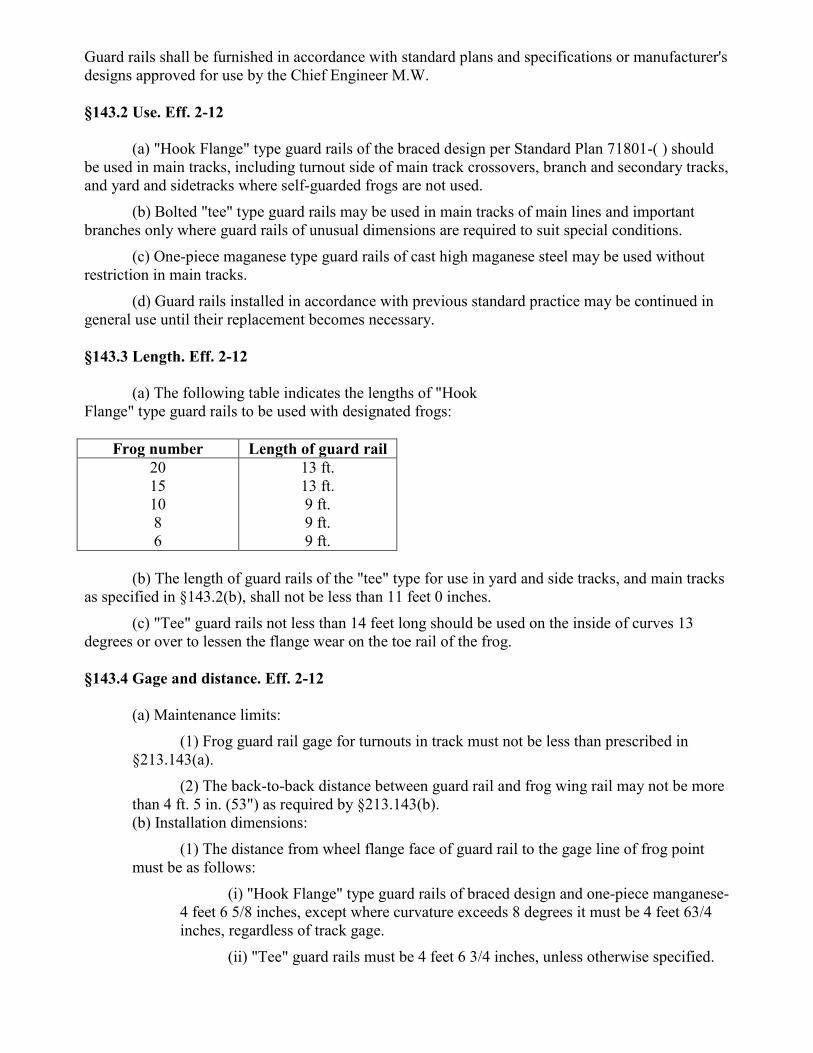
Guard rails shall be furnished in accordance with standard plans and specifications or manufacturer's designs approved for use by the Chief Engineer M.W. §143.2 Use. Eff. 2-12
(a) "Hook Flange" type guard rails of the braced design per Standard Plan 71801-( ) should be used in main tracks, including turnout side of main track crossovers, branch and secondary tracks, and yard and sidetracks where self-guarded frogs are not used.
(b) Bolted "tee" type guard rails may be used in main tracks of main lines and important branches only where guard rails of unusual dimensions are required to suit special conditions.
(c) One-piece maganese type guard rails of cast high maganese steel may be used without restriction in main tracks.
(d) Guard rails installed in accordance with previous standard practice may be continued in general use until their replacement becomes necessary. §143.3 Length. Eff. 2-12
(a) The following table indicates the lengths of "Hook Flange" type guard rails to be used with designated frogs:
Frog number Length of guard rail 20 15 10 8 6
13 ft. 13 ft. 9 ft. 9 ft. 9 ft.
(b) The length of guard rails of the "tee" type for use in yard and side tracks, and main tracks
as specified in §143.2(b), shall not be less than 11 feet 0 inches. (c) "Tee" guard rails not less than 14 feet long should be used on the inside of curves 13
degrees or over to lessen the flange wear on the toe rail of the frog. §143.4 Gage and distance. Eff. 2-12
(a) Maintenance limits: (1) Frog guard rail gage for turnouts in track must not be less than prescribed in
§213.143(a). (2) The back-to-back distance between guard rail and frog wing rail may not be more
than 4 ft. 5 in. (53") as required by §213.143(b). (b) Installation dimensions:
(1) The distance from wheel flange face of guard rail to the gage line of frog point must be as follows:
(i) "Hook Flange" type guard rails of braced design and one-piece manganese-4 feet 6 5/8 inches, except where curvature exceeds 8 degrees it must be 4 feet 63/4 inches, regardless of track gage.
(ii) "Tee" guard rails must be 4 feet 6 3/4 inches, unless otherwise specified.
(2) The distance between wheel flange face of guard rail and the wheel flange face of frog wing rail (back-to back) must not exceed 4 feet 5 inches (53").
§143.5 Application. Eff. 2-12
(a) All guard rails should be set in accordance with Standard Plan 71801-( ). (b) The end of guard rails should be placed upon a tie or be otherwise protected, so that no
loose or dragging object may become hooked on the guard rail ends. §145.0 Inner bridge guard rails. §145.1 General. Eff. 2-12
(a) Where inner bridge guard rails are required, they must be properly installed and maintained to prevent serious structural damage, with possible failure of bridge, in the event of a derailment. Installation of inner guard rails on structures should be held to a minimum to eliminate the extra maintenance needed, and to permit proper surfacing, lining and economical renewal of ties on bridge approaches. Where existing guard rails do not meet the above requirements, installations or removals should be made the next time the track is worked through the area.
(b) A "single" guard rail is a continuous line of rails fastened to ties adjacent to the gage side of one running rail. A "full" guard rail consists of two such lines of rail, one adjacent to the gage side of each running rail. §145.2 Use. Elf. 2-12 The use of inner bridge guard rails shall be, as follows:
(a) Thru truss bridges and other structures supported on piers or on bents that may be struck by derailed equipment with possible failure of the structure, i.e., where piers or bents have considerable batter or extend beyond the bridge trusses due to angular crossing of road, stream, etc.:
(1) Single Track—Full guard rail. (2) Double Track—Single guard rail in each track to deflect derailed wheels away
from adjacent truss. (3) Three or more tracks—Single guard rail in each outside track to deflect derailed
wheels away from adjacent truss. No guard rail is to be placed on other tracks. (b) Movable bridges:
Full guard rail in each track. (c) Special and large structures:
Installation of guard rails must have the approval of the Chief Regional Engineer. §145.3 Material. Eff. 2-12
(a) Preferably, scrap rail will be used, of such a section that the top of guard rail is approximately 1 to 2 inches below the top of the running rail.
(b) Joints may be either 4 or 6 hole bars with a minimum of 4 bolts, without washers, per joint.

(c) No tie plates or braces will be used with inner bridge guard rails. §145.4 Application. Eff. 2-12
(a) Inner guard rails shall extend a sufficient distance (approximately 30 feet) beyond the bridge backwalls on either side. The guard rails should be parallel to and 11 inches from the gage of running rails throughout the entire length of the structure to be protected.
(b) Full guard rails shall end on a tie in the middle of the track. The ends must be beveled, bent down or fitted with a proper end casting, so as to divert a derailed wheel or avoid catching dragging equipment.
(c) Single guard rails shall end on a tie, approximately 12 inches from the gage of the outside running rail, and beveled or bent down so as to avoid catching dragging equipment.
(d) To facilitate diverting derailed wheels, the guard rail shall be lined to a smooth uniform curve and/or tangent from bridge backwall to the guard rail end.
(e) Inner guard rails must be installed to protect the structure from traffic on both directions on that track.
(f) Inner bridge guard rails will be spiked on each cross tie or bridge timber with one spike on each side of the rail or casting, spikes being offset from each other to avoid splitting timber. Spike holes should be prebored. §145.5 Inspection. Eff. 2-12 Inner guard rails shall be inspected periodically to make certain that bolts and joints are tight, spikes firmly against base of rail, and castings fastened securely to rail ends, or ends properly beveled or bent down. Subpart E — Mechanisms, Applicances and Devices §201.0 Switch operating mechanisms §201.1 Use Eff. 2-12 Switches shall be operated by approved types of mechanisms as follows:
(a) Power operated switch mechanisms in accordance with "Specifications for Signal and Interlocking Systems" and Standard Signal Plans.
(b) Manually operated switch mechanisms, which are supplemented by slow acting spring devices, which permit wheels to trail through switches set for the opposite route, referred to as "slow acting spring switch echanisms", may be used with the approval of the General Manager and Chief Engineer M.W., as follows:
(1) In tracks other than yard tracks, when they are equipped with electric switch lamp or switch position indicator, "SS" spring switch marker and provided with signal protection in accordance with "Specifications for Signal and Interlocking Systems". Where track speed is in excess of 50 M.P.H., facing point locking must be provided for the switch in its normal position.
(2) In Yard tracks, without facing point lock and signal protection.

(c) Manually operated mechanisms, combined in one unit, which throw the switch points and also provide for locking them in normal and/or reverse position, referred to as "locking switch stands", may be used as follows:
(1) In main tracks in automatic block territory. (2) In main tracks in other than automatic block territory and in other tracks where
switches are protected by signals controlled over track circuits. (3) In tracks, other than covered in paragraphs (1) and (2) above, only when approved
by the General Manager and Chief Engineer M.W.
Approved types of mechanisms are: Waco Style T-20 G.R.S. Model 9
(d) Manually operated switch mechanisms, of the non-automatic type, which throw the
switch points, referred to as "switch stands", may be used in main tracks, branch lines and secondary tracks, yard and sidetracks, without restriction. Conrail Standard type of switch stand is the New Century Model 50.
(e) Manually operated mechanisms, the position of which is automatically reversed by wheels trailed through a switch set for the opposite route, and referred to as "semi-automatic switch stands", may be used in yards and sidings where authorized by Timetable Special Instructions.
(1) Conrail Standard types of stands are: Bethlehem No. 22 Abex No. 22
(2) Where Timetable Special Instructions permit trains and locomotives to trail through a switch set for the opposite route, the color of the switch stand shall be orange. The color shall be black at other locations. (f) Existing switch stands of other than approved types need not be replaced until worn out,
defective, or otherwise instructed by Chief Engineer M.W. §201.2 Spring switches. Eff. 2-12
(a) Specially reinforced switch points should be used with slow acting spring switch mechanisms.
(b) Where slow acting spring switch mechanisms are in service, maximum permissible speeds for trains and locomotives shall be: Train Movements Speed
Over turnouts in §201.1(b) (1)
Over turnouts in §201.1(b) (2)
Facing, or Trailing – Not springing switch. Trailing – Springing switch.
As otherwise authorized for turnout or track As authorized for turnout or track but not to exceed 45 mph
As authorized for turnout or track, but not to exceed 20 mph. As authorized for turnout or track, but not to exceed 20 mph

§201.3 Application of switch stands. Eff. 2-12
(a) Manually operated switch stands shall be placed so that the operating rod is in tension when the switch is set in normal position in main track, and at the siding end of crossovers between main track and siding.
(b) Each switch in a crossover shall be equipped with a switch stand. (c) Where crossover switches are protected by signals, a switch locking arrangement shall be
provided in accordance with Standard Signal Plans. (d) Where crossover switches between main tracks, or main track and siding, are not
protected by signals, when approved by the General Manager and the Chief Engineer M.W., mechanical switch locking shall be provided in accordance with Standard Signal Plans.
(e) Switch stands for all other tracks shall be located to serve the safety and efficiency of employees in the best manner. §201.4 Location of switch stands. Eff. 2-12
(a) Switch stands, except locking switch stands, with or without switch point position indicators, and stands for indicators must be placed so that the distance from the gage or nearest rail to the center of spindle will be:
(1) With low mast and placed between tracks whose center to center distance is: Track center distance Minimum distance from gage to center
of spindle 12 ft. 2 in. to 13 ft. 0 in. 13 ft. 0 in. or more
3 ft. 8 ¾ in. 4 ft. 1 in.
(2) For stands when not between tracks, a minimum distance from gage to center of
spindle: With low masts - 4 ft. 1 in. With intermediate or - 7 ft. 0 in. high masts (3) Where switches are so close together that switch position indicators, if of the
same height, would not be separately visible from the locomotive cab, one stand should be placed further from the track than the other, preferably by a distance of 18 inches where track center distances permit. (b) "Locking switch stands" shall be placed so that the center line of the lock bar is 30 inches
from the gage of the stock rail for a Wabco Style T-20 and 42 inches for a G.R.S. Model 9. §201.5 Padlocks. Eff. 2-12
(a) At all non-interlocked main and secondary track switches, throw levers of switch stands shall be secured by two latches and locked by a standard switch padlock. The padlock is to be fastened by a chain to the switch stand or tie so that the switch can be locked only in the normal position.
(b) Where the switch is provided with a separate facing point lock not operated by the throw lever of the switch stand, the padlock shall be placed for locking the facing point lock lever only.

(c) The throw levers of switch stands in other than main and secondary tracks shall be provided with latches, but shall be provided with padlocks only when authorized by the Superintendent. §201.6 Maintenance. Eff. 2-12
(a) Switches, switch stands and operating rods must be examined frequently. Broken, damaged or missing parts shall be renewed immediately.
(b) Regular inspections shall be made as required by Form MW 41. If necessary, corrective action must be taken immediately.
(c) Worn switch latches must be replaced before the wear is sufficient to permit the switch to be opened without removing the padlock.
(d) The requirements of §213.135(e) and (f), and §213.235 must be met in maintaining and inspecting switch stands.
(e) Model No. 22 semi-automatic switch stands which do not operate satisfactorily can no longer be adjusted properly should be replaced. The released stands should be sent to a Material Distribution Center for rehabilitation.
(f) Switch heaters must not interfere with the proper operation of the switch or otherwise jeopardize the safety of railroad equipment. §202.0 Switch point position indicators. §202.1 General. Eff. 2-12
(a) To give a clear and distinct indication of the position of switch points, when non-interlocked, lamps with colored enamel discs, or reflectorized targets in accordance with Standard Plans 73917( ) and 73919( ), shall be provided at locations approved by the General Manager, except where it has been decided that due to the character of traffic the indication is not necessary.
(b) Switch position indicators (lamps and reflectorized targets) are classified according to the height of the center of lens or target above the track ties as follows:
(1) "Low"—Not exceeding 20 inches. (2) "Intermediate"-8 feet 11 inches. (3) "High"-17 feet.
(c) Indicators should be used, when required, at noninterlocked switches as follows: (1) Low type with lamp and colored enamel discs or reflectorized target should be
used generally in all tracks. (2) Intermediate type with either lamp or reflectorized target should be used only at
facing switches in nonautomatic territory where sufficient visibility is not afforded by the low type, and a high type is not warranted.
(3) High type with either lamp or reflectorized target should be used only at facing switches in non-automatic territory where sufficient visibility is not afforded by the intermediate type.

§202.2 Application. Eff. 2-12
(a) Switch point position indicators may be placed on a low switch lamp stand and connected to the switch points or they may be placed directly on the switch stand.
(b) Targets and lamps shall be set at right angles to the track and be perpendicular to the head ties. Where targets are used, the upward point of the inclined blade shall be away from the track, when the switch is set normal for the main track. §202.3 Maintenance. Eff. 2-12 Switch point position indicators should be kept clean and of uniform brightness and visibility. §202.4 Position indication. Eff. 2-12
(a) Day and night color of position indicators for switch points shall be in accordance with the following table:
Location of
Switch
Switch Normal Switch Reverse Day Night Day Night
Dis
cs o
r Tar
gets
Col
ored
Len
ses
or R
efle
ctor
s
Dis
cs o
r Tar
gets
Col
ored
Len
ses
or R
efle
ctor
s
(1) In Main Track White or Green Green Red Red
(2) In all other tracks including siding switch or crossover between siding and main track.
White or Green Green Yellow Yellow
(b) Electric switch lamp connected to spring switch indicates:
(1) Green when switch is closed and locked. (2) Red when switch is unlocked or open.
(c) Regulations issued by public authorities require the use of lamps under certain circumstances, and must be compiled with.
(d) Where the use of a switch lamp or target is normally required, and a switch has been placed out of service, the lamp or target shall remain in service unless the switch, frog and lead rails have been entirely removed. §203.0 Hot box detectors. §203.1 Application. Eff. 2-12

Hot box detectors should be placed on tangent track, and at least 500 feet from nearest turnout or end of curve. §203.2 Track condition. Eff. 2-12
(a) At all hot box detector locations, special attention must be given to the maintenance of good gage, surface and line for 100 feet approaching and through the detector to insure that the top of the rail is at proper height with respect to scanners and that the wheels are properly centered with regard to the gage of the track in passing over the detector.
(b) Rail joints should be at least 5 feet from the transducers. (c) The rail on which the transducers are located should be effectively anchored to restrict
movement of the rail. §203.3 Track work in vicinity. Eff. 2-12 Whenever track work is to be done in the vicinity of the detector, which may affect the vertical or horizontal relationship of the rails with respect to scanners, the C. & S. Department must be notified so that the device can be regaged. §203.4 Interference by metal objects. Eff. 2-12 Employees must be careful not to pass any iron or steel object closely over transducers (coils that are mounted on the side of the rail) between the time that a train has passed over the detector and until the train has passed the home signal in advance to avoid possibility of causing home signal to display stop aspect in face of the train. §205.0 Derails. §205.1 Position. Eff. 2-12 The "Normal" position of a derail shall be to derail wheels of rolling equipment. The "Reverse" positions shall be to leave the rails unobstructed for free movement of the equipment. §205.2 Use of derails. Eff. 2-12 Derails shall be used as follows:
(a) In main tracks, secondary tracks, controlled sidings and sidings, only where required by Federal or State Authorities or where authorized by the Chief Engineer M.W.
(b) In all other tracks connected with main tracks except: (1) Where on account of ascending grade and/or other local conditions there is no
possibility of rolling equipment drifting beyond a determined point of safety, which shall be indicated by a yellow stripe, about 10 inches wide painted on the inside and outside of head, web and base of both rails, which must be kept clear of dirt and weeds, and repainted as often as necessary. (In determining the ascending grade that will prevent equipment from drifting beyond the point of safety, grades on the entire track must be considered. Wind pressure will cause rolling equipment to move against any ascending grade less than 0.5 percent.)
(2) Where a track is located between main tracks and connected with both at the same end, in which case the "Middle Siding Layout for Hand Operated End Switches", PRR Plan

73930-( ) shall apply. If such a track is temporarily used to store cars, place a car stop close to the stored cars while the track is so occupied, unless made unnecessary by reason of an ascending grade.
(3) Where slow acting spring switches are authorized. (c) With guiding rail guards where track is located between main tracks not connected with
both at the same end, to make sure the derailed rolling equipment will not foul the adjacent track. If such a track is temporarily used to store cars, place a car stop close to the stored cars while the track is so occupied, unless made unnecessary by reason of an ascending grade.
(d) In an outside main track, if temporarily used to store cars, place a derail close to the stored cars while the track is so occupied, unless made unnecessary by reason of an ascending grade. If the main track on which cars are stored in between other main tracks, place a car stop close to the stored cars instead of a derail, unless made unnecessary by reason of an ascending grade.
(e) In accordance with Blue Signal Protection, Rule 26 of the "Rules of the Transportation Department".
(f) At other points where deemed necessary, and authorized by the Chief Engineer M.W. §205.3 Types of derails. Eff. 2-12
(a) Derails are generally of two kinds, the "split switch" and the sliding or hinged "block" type.
(b) Where derails are prescribed, the split switch type shall be used as follows: (1) Within interlocking limits, in main tracks and in secondary tracks. (2) At non-interlocked and non-signaled branch line junctions. (3) In all other tracks where it is possible for the speed of rolling equipment to exceed
15 mph. (c) Approved block type derails shall be used at locations other than those required in
paragraph (b) above, where derails are required. §205.4 Application. Eff. 2-12
(a) A derail shall be placed a sufficient distance back of the clearance point, not less than 12 feet, to assure that derailed rolling equipment will not foul the main or other protected track. Clearance requirements and track center distances are defined in Section 62.0.
(b) Methods for installing sliding and hand thrown type derails are shown on Standard Plans 73920-( ), 73921-( ) and 73922-( ).
(c) Where tracks are not parallel at the derail location, or due to other local conditions, it may be necessary to use a deflecting rail to make sure that derailed rolling equipment will not continue moving over the ties to foul the protected track.
(d) Where deflecting rails are used: (1) The minimum length shall be 18 feet. (2) The nearest end shall be 10 feet from the derail. (3) The flangeway opening at the end nearest to the derail shall be 4 inches. (4) The end farthest from the derail shall be set to provide a 12 inch clear opening
between running rail opposite the derail and the deflecting rail.

(5) The deflecting rail shall be of a section and weight not greater than that of the running rails, and preferably less.
(6) The deflecting rail should be spiked to every tie with two rail holding spikes, one on each side of the rail base.
(7) Neither tie plates nor rail braces are to be used unless special circumstances indicate the need.
(8) Existing installations of derails need not be changed to meet these provisions until renewals are otherwise necessary.
§205.5 Operation of derails. Eff. 2-12
(a) In signaled territory outside of interlocking limits: (1) Where the main track switch is protected by a facing point lock, the derail may be
operated by a pipe line connected to the main track switch throwing and locking mechanisms, which operates both the switch and the facing lock in accordance with Standard Signal Plan.
(2) Where a pipe connected derail is not provided, an independently operated derail at fouling point shall be used, which must be equipped with a track circuit controller, so connected that the signal protecting the main track switch will display its most restricting indication when the derail is not in derailing position. (b) In manual block territory, the derail may be operated by a pipe line connected to the main
track switch stand where considered necessary and authorized by the Chief Engineer M.W. (c) All derails not operated by pipe lines shall be provided with standard switch padlocks
fastened to the tie by a chain and staple, so that the lever or derail can be locked only in the normal position.
(d) Lever stands of approved types may be used for operating derails. The distance from center line of lever stand spindle to the gage of nearest rail shall be at least 4 feet 1 inch, where practicable. §205.6 Position indication. Eff. 2-12 The position of non-interlocked derails, normal or reverse, shall be indicated as follows:
(a) Where train movements are made at night. the derail shall display a red reflectorized target when in normal position to derail, unless a lighted lamp is required by a public authority. If lighted lamp is used, it shall display a red light when derail is in normal position to derail and a yellow light in the reverse position.
(b) In daytime, no other indication than the position of the derail itself is necessary. §205.7 Maintenance. Eff. 2-12
(a) Derailing blocks shall be painted yellow. Other parts of derails shall be painted black. (b) Pipe connections for operating derails must be kept free from lost motion. All the
fastenings must be tight and in correct alinement, and ties under supports must be sound. Frequent tests shall be made to ascertain if any switch levers can be thrown and latched without the derail moving to the correct position, either normal or reverse.

(c) Dirt and weeds must be kept away from derails. (d) When derails other than those here in specified are in use and giving satisfactory service,
they should be retained until replacement is necessary. §206.0 Rail Lubricators. Eff. 2-12 (a) Lubricators may be installed wherever Region or Division consider necessary to extend the serviceable life of rail. (b) Correct location of the lubricators is as important as their maintenance; therefore a form titled Rail Lubricator Calculations must be used to determine whether or not adequate lubrication will be provided. (c) A completed form showing the location calculations must be submitted to the Office of the Chief Engineer, M.W., for review with each lubricator requisition. Index—Standard Plans. 70003-B Roadway Stone Ballast 70051-G Minimum Roadway Clearances 70123-G Prefabricated Timbers for Blacktop Highway 71325-A Location of insulated joints (3 Sheets) 71801-B Guard Rail Installation and Maintenance 72051-B Spiking Arrangements for Tie Plates 73062-E 60' Undercut Stock Rails 73184-0 No. 8 Welded Turnout Tie and Rail Layout with Pandrol Fasteners (Sheet 1 of 2) 73184-K Bill of Material—No. 8, 10, 15, 20 Welded Turnouts with Pandrol Fasteners (Sheet 2 of 2) 73185-M No. 10 Welded Turnout Tie and Rail Layout with Pandrol Fasteners 73186-M No. 15 Welded Turnout Tie and Rail Layout with Pandrol Fasteners 73187-N No. 20 Welded Turnout Tie and Rail Layout with Pandrol Fasteners 73206-D No. 8 Paneled Welded Turnout Tie and Rail Layout 73207-D No. 10 Paneled Welded Turnout Tie and Rail Layout 73208-F No. 8 Paneled Welded Turnout Tie and Rail Layout with Pandrol Fasteners 73209-F No. 10 Paneled Welded Turnout Tie and Rail Layout with Pandrol Fasteners 73210-G Bill of Material—No. 8, 10, 15, 20 Welded Paneled Switch Turnouts with Pandrol Fasteners 73211-B No. 15 Paneled Welded Turnout Tie and Rail Layout with Pandrol Fasteners 73212-A No. 20 Paneled Welded Turnout Tie and Rail Layout with Pandrol Fasteners 73514-G Rods and Clips for 39'0" Switch 73516-G Rods and Clips for 26'0" Switch 73518-G Rods and Clips for 16'6" Switch

Section II PennDOT specfications (Revised 5/09) The purpose of this trackwork inspection criterion is to provide minimum material and workmanship requirements for common construction items identified in typical track rehabilitation or construction contracts involving Department participation. GENERAL Upon completion of any work, all rubbish, waste, old ties, or any other waste material removed from the tracks shall be cleaned up and properly disposed of offsite. Any steel products used in the performance of the Agreement shall adhere to the Steel Products
Procurement Act (Ref. Steel Products Procurement Act 73 P.S. § 1881, et seq.). Certification shall
be provided if requested. Unless specified in these criteria, track material and workmanship shall conform to the AREMA Manual, be free of defects and of the proper size. Deviations shall be approved by the Department. Ballast (crushed stone) shall be used and must be free of screenings, dirt and foreign matter. Gradation shall comply with AREMA Manual. All bituminous material used for highway grade crossings shall be suitable for permanent construction and repairs and be similar in type durability to materials used by local, county and state highway departments in the area. Work must be in compliance with environmental regulations applicable to the nature of the work performed. ITEM #1: CROSS TIES DESCRIPTION: This work shall consist of furnishing and distributing the required number of ties, installation of replacement ties, removal of and disposal of defective ties, replacement of tie plates, spiking of the replacement ties, tamping, replacement of rail anchors, and dressing of ballast. MATERIAL: Ties shall be oak and mixed hardwoods and conform to AREMA specifications. Ties shall not be industrial grade, plant rejects, or relays unless written permission is received from the Department. New treated cross ties will be installed and shall measure a minimum of 6"x8"x8'-6" (15.24cm x 20.32cm x 2.5908m), except that ties may have a tolerance of -1/4" (6.35mm) to +3/4" (19.05mm) width and height and be 1" (2.54cm) shorter or longer than the length of 8'-6" (2.5908m). Cross ties shall be treated with a 60/40 creosote-coal tar solution per cubic foot (meter) of material. Treatment reports shall be provided if requested. WORKMANSHIP: All ties will be placed with the heartwood face down, square with the line of rail and approximately centered with the track. Replaced ties shall be brought up tight against the base of the rail and be tamped with an appropriate device. Ties shall be handled with tie tongs or an approved mechanical device. The use of a pick is not allowed. All replacement ties shall be spiked to the standard gage of 56 1/2" (143.51cm) plus 1/2" (1.27cm). In areas where ties are spotted in, blending of the existing ties shall be required. Where spikes are withdrawn, the holes in the tie must be plugged with a creosoted tie plug. Spikes shall be driven vertically and square against the rail and driven to allow 1/8" (3.175mm) to 3/16" (4.7625mm) space between the spikes head underside and top of rail base. No spikes shall be driven into the joint bar slot or at the joint bar ends to prevent skewing of the ties. Tie plates shall be centered on the tie under the rail with the base of the rail bearing firmly against the tie plate. Under no circumstances shall the shoulder of the plate be under the base of the rail. Rail anchors disturbed as a result of the work shall be reinstalled as per existing anchor pattern.

METHOD OF MEASUREMENT: This item will be measured by a unit for each tie properly installed. ITEM #2: SWITCH TIES DESCRIPTION: This work consists of furnishing and distributing switch ties, removing and disposing of defective switch ties, installation of replacement switch parts and tie plates as required, spiking, tamping, and dressing ballast. MATERIAL: Switch ties shall conform to the AREMA Manual. Material and treatment shall be the same as for crossties. WORKMANSHIP: Workmanship as described in Item 1 applies. Also the distance from the field side base of rail to the end of tie shall be in the range of 13"(33.02cm) - 24" (60.96cm) for both ends of the switch tie. METHOD OF MEASUREMENT: This item will be measured by the number of linear feet ( linear meters) of switch ties installed and accepted. ITEM #3: JOINTED RAIL DESCRIPTION: This work consists of furnishing and distributing required length of rail, rail installation, disposal of replaced rail, tie plate installation, spiking, and rail anchor installation. MATERIAL: Rail shall conform to the AREMA Manual and be of the same or equivalent weight and section as that being replaced. Rail less than 14' (4.2672m) may not be used as replacement rail. Rail bought for the project shall not exceed the allowable wear specified for Class I rail in the AREMA manual. WORKMANSHIP: Rail shall be cut with a saw and new bolt holes drilled. A torch shall not be used for these operations. Rail end mismatch greater than 3/16" (4.7625mm) shall have the lower rail built up with welded metal so that the rail end mismatch on the tread and gage side is less than 1/8" (3.175mm). Proper welding specifications shall be determined by the contractor performing the welding operation and acceptable to the Department. All rail shall be laid to the standard gage of 56-1/2"(143.51cm) plus 1/2"(1.27cm). For securing the rail to the ties, workmanship as described in Item 1 applies. METHOD OF MEASUREMENT: This item will be measured and accepted by the number of linear feet (linear meters) of rail installed and accepted. ITEM #4: CONTINOUS WELDED RAIL (CWR) DESCRIPTION: This work consists of furnishing and distributing required length of CWR, rail installation, disposal of replaced rail, tie plate installation, spiking, and rail anchor installation. MATERIAL: CWR shall conform to the AREMA Manual. CWR shall not have holes closer than 4 1/2" (11.43cm) to the weld. All tie holes shall be plugged with treated plugs. All CWR rail shall be laid to the standard gage of 56-1/2"(143.51cm). Every tie shall be box anchored for 200'(60.96m) beyond each bolted end of the CWR strings, each end of road crossings, and each end of switches. Ballast shall extend beyond the tie ends at least 12"(30.48cm). Rail shall be cut with a saw and new bolt holes drilled; a torch shall not be used for these operations. The end of the replacement rail shall, when necessary, be ground or built up with welded metal so that the rail end mismatch on the tread and gage side is less than 1/8" (3.175mm). Proper welding specifications shall be determined by the contractor performing the welding operation and acceptable to the Department. For securing the rail, workmanship as described in Item 1 applies.

METHOD OF MEASUREMENT: This item will be measured and accepted by the number of linear feet (linear meters) of rail installed and accepted. ITEM #5: RAISING, LINING AND SURFACING DESCRIPTION: This work consists of raising, lining and leveling the track to specifications; installing ballast; spiking and tamping all ties; tightening of joints; and regulating ballast. MATERIAL: Ballast shall conform to AREMA No. 3/AASHTO No. 3 or AREMA No. 4. specifications. WORKMANSHIP: Adequate ballast for dressing to the proper cross section should be distributed in advance of raising. All joints in the work limits must be tightened prior to beginning the surfacing work. Work should comply with the AREMA Manual. All spikes should be driven down taken care not to overdrive. All ties must have a tight bearing against the base of the rail, all joints must be retightened and ballast must be regulated and dressed after surfacing and lining are completed. METHOD OF MEASUREMENT: This item will be measured by the track feet (track meter) surfaced and accepted. ITEM #6: SPOT SURFACING DESCRIPTION: This work consists of installing the necessary ballast, tamping all low spots, sink holes, down ties, respiking improperly spiked ties and realigning track areas where needed. MATERIAL: Ballast shall conform to AREMA No. 3/AASHTO No. 3 or AREA No. 4 specifications. WORKMANSHIP: All cribs are to be filled with ballast and ties tamped up tightly to the base of rail. Down ties are to be plugged, respiked and tamped up tightly to the base of rail. Work area must be properly dressed after completion of surfacing. METHOD OF MEASUREMENT: This item will be measured by the actual number of track feet (track meter) spot surfaced and accepted. ITEM #7: BRIDGE DECK REPAIR DESCRIPTION: This work consists of furnishing and distributing bridge ties, removing and disposing of defective ties, installing replacement ties, reinstalling tie plates, spiking, installing tie bolts, and installing tie spacer bar or timber. MATERIAL: All material shall conform to the AREMA Manual. WORKMANSHIP: New properly treated bridge ties of the same size shall be used unless otherwise specified. Bridge ties shall be dapped and fitted to support the running rails at the proper grade and elevation across the entire length of the bridge. Workmanship in Item 1 applies where practicable. All joints on the bridge deck shall be tightened upon completion of bridge timber installation. METHOD OF MEASUREMENT: This item will be measured by the number of bridge ties installed and accepted. ITEM #8: ROAD CROSSING REBUILDING DESCRIPTION: Work shall consist of obtaining the necessary approval from the proper highway authority; providing proper protection to the public; providing for detour as required; saw cutting existing pavement; roll tamping ballast in no more than 6" (15.24cm) lifts; removing and disposing of all old materials; furnishing and replacing all

cross ties within the crossing; furnishing welded rail through the crossing with the first joint to be no closer than 6' (1.8288m) from the edge of the crossing; furnishing, placing and compacting bituminous material; providing the proper overlay transition and paving notch; sealing joints; and providing flangeways and drainage facilities. The crossing will be tamped and surfaced with new ballast to the grade and elevation consistent with the adjacent track and roadway. MATERIALS: All materials shall comply with the AREMA Manual, except for bituminous materials which shall comply with local, county, or state highway departments in the location of work. WORKMANSHIP: Ties installed shall be tamped firmly against the base of the rail on a bed of new ballast of the required depth. Workmanship in Item 1 applies. After track is brought to the proper line and surface, coarse grade blacktop (BCBC) will be placed within the roadway limits of the crossing to a depth from 2"(5.08cm) below the plane of the top of the rails to the plane of the top of the ties and properly compacted. Surface grade blacktop (ID-2) will be placed to a depth from the plane of the top of the rails to the coarse grade blacktop and be properly compacted and rolled to provide a uniform surface at the elevation of the top of the rails. Overlay transition with existing roadway and paving notch must comply with PA DOT Pub. 72 Drawing. No. RC-28 (Figure 2). Flangeways 2 1/2"(6.35cm) wide and 2 1/2"(6.35cm) deep will be provided along the gage side of the rails. Should crossing timbers be used, they shall be of proper size, fastened with lag screws and cover the full width of the crossing. Crossing timbers will be flush against the rail on the field side. On the gage side they will be 2 1/2"(6.35cm) from the edge of the rail. All debris from the crossing will be disposed of. Roadway shoulders should be graded and dressed. METHOD OF MEASUREMENT: This item will be measured by the linear feet (linear meter) of crossing replaced. NOTE: Drainage facilities may include filter fabrics and/or drainage pipe depending on the merits of each individual crossing. If filter fabric is used below the tracks, the fabric shall be a minimum of 16 oz. (457.14 grams) and be a minimum of 10"(25.4cm) below the bottom of the ties. ITEM # 9: TRACK CONSTRUCTION DESCRIPTION: This work shall consist of the following: - Preparation of the subgrade including all clearing, excavating, filling and grading necessary for the placement of the railroad track. - Furnishing, distributing and assembling all components of the railroad track. Description and workmanship in Items 1 through 9 apply where practicable. - Placing a minimum of 6" (15.24cm) of subballast (such as 2A Modified) in no more than 4" (10.16cm) lifts. Each lift is to be compacted until nonmovement of material exists beneath compaction equipment. - Placing a minimum of 6" (15.24cm) of ballast below the ties. - Final leveling and alignment of track. MATERIAL: All materials shall conform to the AREMA Manual. WORKMANSHIP: Work shall comply with the AREMA Manual, workmanship as described in Items 1 through 9 and Figure 1 attached as page eight (8). METHOD OF MEASUREMENT: This item will be measured by the track feet (track meters) of railroad track constructed and accepted

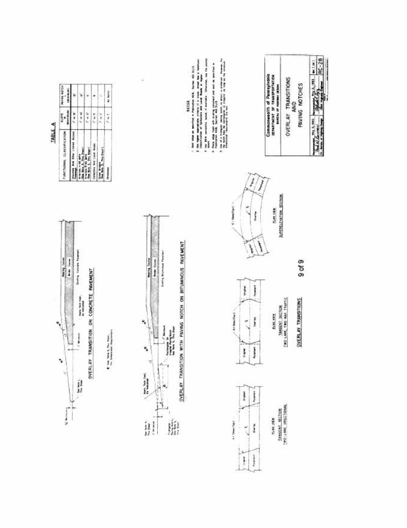


Unitrac Railroad Materials Inc.
1
Rail Sections
Tee Rail DataDiagram
Dimensions for TeeRail Data Table
HT - Height
BW - Width of Base
HW - Width of Head
W - Web(at center point)
HD - Depth of Head
FD - Fishing
BD - Depth of Base
E - Bolt Hole Elevation

2
Unitrac Railroad Materials Inc.
Rail Sections
HT - Height
BW - Width of Base
HW - Width of Head
W - Web(at center point)
HD - Depth of Head
FD - Fishing
BD - Depth of Base
E - Bolt Hole Elevation
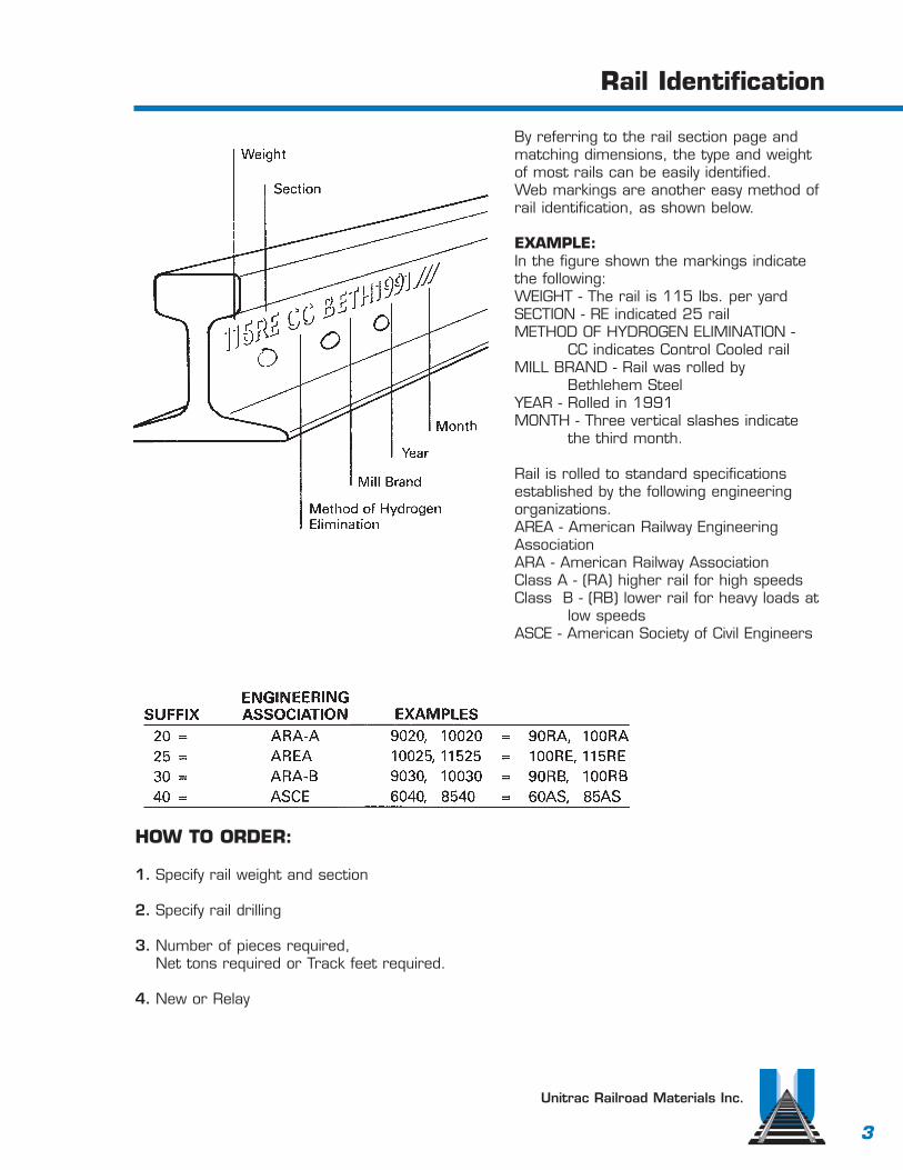
3
Unitrac Railroad Materials Inc.
Rail Identification
By referring to the rail section page andmatching dimensions, the type and weightof most rails can be easily identified.Web markings are another easy method ofrail identification, as shown below.
EXAMPLE:In the figure shown the markings indicatethe following:WEIGHT - The rail is 115 lbs. per yardSECTION - RE indicated 25 railMETHOD OF HYDROGEN ELIMINATION -
CC indicates Control Cooled railMILL BRAND - Rail was rolled by
Bethlehem Steel YEAR - Rolled in 1991MONTH - Three vertical slashes indicate
the third month.
Rail is rolled to standard specificationsestablished by the following engineeringorganizations.AREA - American Railway EngineeringAssociationARA - American Railway AssociationClass A - (RA) higher rail for high speedsClass B - (RB) lower rail for heavy loads at
low speedsASCE - American Society of Civil Engineers
HOW TO ORDER:
1. Specify rail weight and section
2. Specify rail drilling
3. Number of pieces required, Net tons required or Track feet required.
4. New or Relay

4
Unitrac Railroad Materials Inc.
140 3/8 3/4132-131 5/16 3/4122 5/16 3/4115 5/16 3/4112 5/16 1/2100 3/16 1/490 1/4 3/16
140 1/4 1/2132-131 3/16 1/2122 5/32 7/16115 1/8 3/8112 1/8 1/4100 1/8 1/890 1/8 1/8
Rail Grading for Relay Rail
Rail Maximum Rail Wear - Inches General Rail Use & Rail ConditionWeight Top Gage
Class I
Main Line use - Very minor engineburns and corrugation.
Class II
Branch Lines - Small engine burnsand corrugation.
Class III140 5/8 7/8132-131 7/16 7/8122 1/2 7/8115 3/8 3/4112 3/8 3/4100 1/4 1/490 5/16 5/16
Light Branch Lines - Medium engineburns and corrugation, may bepitted and show some oxidation.
Class IV140 3/4 1132-131 9/16 1122 11/16 1115 1/2 7/8112 1/2 7/8100 7/16 7/890 3/8 3/8
Yards - Any burns not mashed orfractured.
Taken from the A.R.E.A. manual for railway engineering. 4-2-60

20-lb. A.S.C.E. Rail
RAIL20 lbs. per yard
35.2 net tons per mile of track150 feet of track per net ton
Stock lengths 20’0” and 30’0”
SPLICE BARS16 1/8 length 4.2 lbs per pair
12-lb. A.S.C.E. Rail
RAIL12 lbs. per yard
21.12 net tons per mile of track250 feet of track per ton
Stock length 20’0”
SPLICE BARS16 1/8” length 2.9 lbs. per pair
Unitrac Railroad Materials Inc.
5

30-lb. A.S.C.E. Rail
RAIL30 lbs. per yard52.8 net tons per mile of track100 feet of track per net tonStock lengths 20’0” and 30’0”
ANGLE BARS10.9 lbs. per pair
SPLICE BARS7.0 lbs. per pair16 1/8” length
Unitrac Railroad Materials Inc.
6

Unitrac Railroad Materials Inc.
7
40-lb. A.S.C.E. Rail
RAIL40 lbs. per yard
70.4 net tons per mile of track75 feet of track per net ton
Stock length 30’0”
ANGLE BARS15.2 lbs. per pair
SPLICE BARS12.0 lbs. per pair 20” length

8
60-lb. A.S.C.E. Rail
RAIL60 lbs. per yard105.6 net tons per mile of track50 feet of track per net tonStock length 30’0”
ANGLE BARS20” length 27.2 lbs. per pair24” length 32.5 lbs. per pair
Unitrac Railroad Materials Inc.

85-lb. A.S.C.E. Rail
RAIL85 lbs. per yard
149.6 net tons per mile of track35.3 feet of track per net ton
Stock length 39’0”
ANGLE BARS24” length 49.6 lbs. per pair
(Toeless and Headfree bars also available)
Unitrac Railroad Materials Inc.
9

10
100-lb. A.R.E.A. Rail
RAIL101.5 lbs. per yard176 net tons per mile of trackStock length 39’0”
ANGLE BARS24” length 69.5 lbs. per pair
Unitrac Railroad Materials Inc.
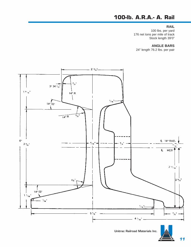
100-lb. A.R.A.- A. Rail
RAIL100 lbs. per yard
176 net tons per mile of trackStock length 39’0”
ANGLE BARS24” length 76.2 lbs. per pair
Unitrac Railroad Materials Inc.
11

12
100-lb. RB Rail
RAIL SECTION 10030100 lbs. per yard176 net tons per mile of trackStock length 39’0”
ANGLE BARS24” length 67.7 lbs. per pair
Unitrac Railroad Materials Inc.

13
Unitrac Railroad Materials Inc.
115-lb. A.R.E.A. Rail
RAIL115 lbs. per yard
202.4 net tons per mile of trackStock length 39’0”
JOINT BARS24” length 62.54 lbs. per pair36” length 93.84 lbs. per pair

14
132-lb. A.R.E.A. Rail
RAIL132 lbs. per yard232.3 net tons per mile of trackStock length 39’0”
JOINT BARS24” length 75.37 lbs. per pair36” length 113.06 lbs. per pair
Unitrac Railroad Materials Inc.

15
Unitrac Railroad Materials Inc.
136-lb. A.R.E.A. Rail
RAIL JOINT BARS136 lbs. per yard 24” length 76.8 lbs. per pair240.8 net tons per mile of track 24” length 76.8 lbs. per pairStock length 39’0” 36” length 115.2 lbs. per pair

16
140-lb. A.R.E.A. Rail
RAIL - SECTION 140 JOINT BARS140 lbs. per yard 24” length 81.6 lbs. per pair247.72 net tons per mile of track 36” length 122.4 lbs. per pairStock length 39’0”
Unitrac Railroad Materials Inc.
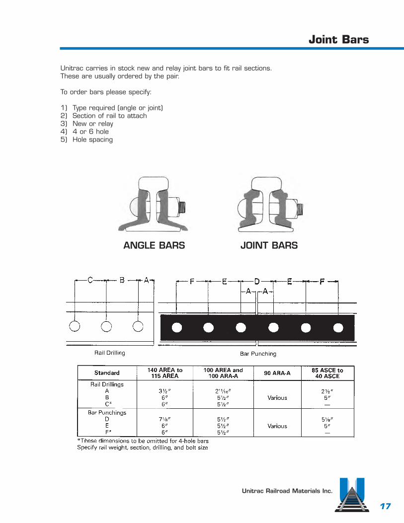
Unitrac Railroad Materials Inc.
17
Joint Bars
Unitrac carries in stock new and relay joint bars to fit rail sections.These are usually ordered by the pair.
To order bars please specify:
1) Type required (angle or joint)2) Section of rail to attach3) New or relay4) 4 or 6 hole5) Hole spacing
ANGLE BARS JOINT BARS
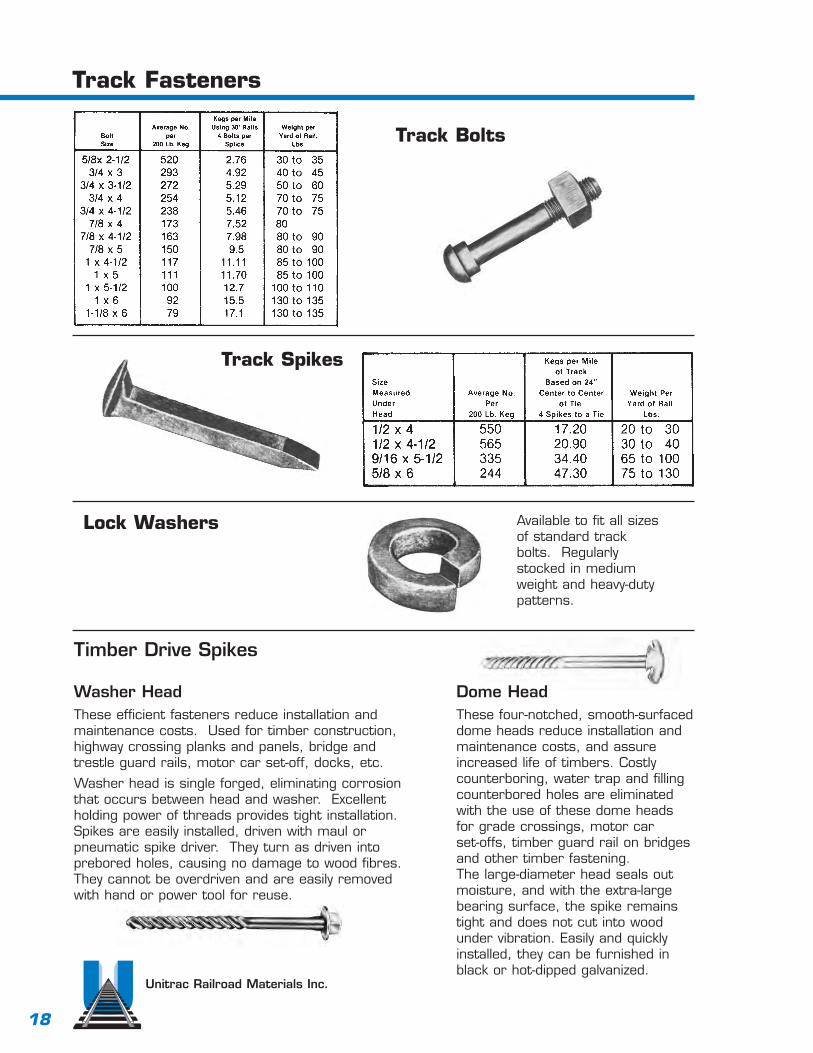
Unitrac Railroad Materials Inc.
18
Track Fasteners
Track Bolts
Track Spikes
Lock Washers
Timber Drive Spikes
Available to fit all sizesof standard trackbolts. Regularlystocked in mediumweight and heavy-dutypatterns.
Dome HeadThese four-notched, smooth-surfaceddome heads reduce installation andmaintenance costs, and assureincreased life of timbers. Costlycounterboring, water trap and fillingcounterbored holes are eliminatedwith the use of these dome headsfor grade crossings, motor car set-offs, timber guard rail on bridgesand other timber fastening. The large-diameter head seals outmoisture, and with the extra-largebearing surface, the spike remainstight and does not cut into woodunder vibration. Easily and quicklyinstalled, they can be furnished inblack or hot-dipped galvanized.
Washer HeadThese efficient fasteners reduce installation andmaintenance costs. Used for timber construction,highway crossing planks and panels, bridge andtrestle guard rails, motor car set-off, docks, etc.
Washer head is single forged, eliminating corrosionthat occurs between head and washer. Excellentholding power of threads provides tight installation.Spikes are easily installed, driven with maul orpneumatic spike driver. They turn as driven intoprebored holes, causing no damage to wood fibres.They cannot be overdriven and are easily removedwith hand or power tool for reuse.

19
Unitrac Railroad Materials Inc.
Tie Plates
The use of single or double shoulder tieplates makes a more stable track andgreatly lengthens the life of wood ties.Punched and sheared from hot-rolledsteel sections, tie plates provide propercant, uniform bearing surface for therail and better load distribution to theties.They hold the rail to gauge, providingmore uniform wear to rail head andprotect against undue wear to ties.Tie plates are designed with a long endor field end to be located outside of therails. In the case of single shoulder tieplates, the shoulder is placed on thefield end of the plate. The gauge end orshort end of the plate is located insideof the rails. When ordering, identificationof the rail section or the width of the railbase should be specified. Quality relayingtie plates are also available from ourstocks which offer appreciable savings onrailroad trackage and industrial sidings.
Single Shoulder
Double Shoulder
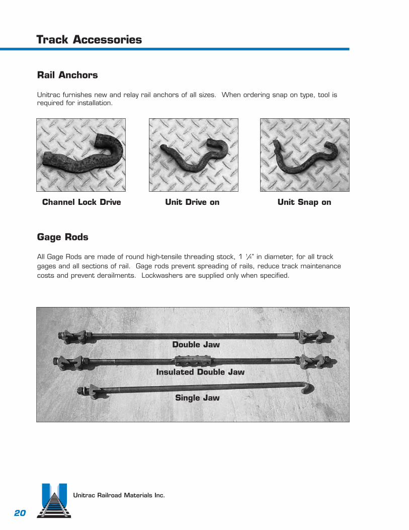
Unitrac Railroad Materials Inc.
20
Track Accessories
Rail Anchors
Unitrac furnishes new and relay rail anchors of all sizes. When ordering snap on type, tool isrequired for installation.
Channel Lock Drive Unit Drive on Unit Snap on
Gage Rods
All Gage Rods are made of round high-tensile threading stock, 1 1/4” in diameter, for all trackgages and all sections of rail. Gage rods prevent spreading of rails, reduce track maintenancecosts and prevent derailments. Lockwashers are supplied only when specified.
Single Jaw
Double Jaw
Insulated Double Jaw

Unitrac Railroad Materials Inc.
21
Track Accessories
Compromise Joint BarsDesigned to join rail sections of differentsizes while keeping gage and running surfacesin alignment. Compromise joints consist iftwo bars - an “outside joint bar” and a“gage side joint bar”. Generally speaking,unless the difference between the rail headwidth is less than 3/16”, right and left-handjoints are required. Unless otherwise specified:1) bolt holes are alternately round and oval,2) bolts are not provided, and3) rail joint opening is 1/8”.
Switch Point ProtectorsThe reversible manganese steelswitch point protector increases thelife of your switch point. When boltedto the inside of the straight mainrail, the protector momentarilydeflects the wheel flange so it missesthe tip of the switch point. It isfurnished complete with steel faceplate, shim, track bolts, nuts andspring washers.To order, specify rail size and section.
To Determine Right-Hand or Left-Hand Joint To DetermineBolt Hole Locations

Unitrac Railroad Materials Inc.
22
Track Accessories
Hook Bolts
Hook bolts are very commonlyused to attach lighter rails(usually up to 85 lbs.) to channels(as shown at left) or directly ontoa crane rail beam. They areusually threaded to allow upto 1/2” lateral adjustment ineither direction, and comecomplete with hex nuts andlockwashers. When ordering,specify rail section, bolt diameter,and the size and weight ofsupporting beam or channel.
Flangway Road Crossing Guards
Rigid steel bars protect concrete or asphaltpaving, provide smooth road crossings level withtop of rails. Specially designed steel castings fitinto web of rail and around rail base and positionflangeway guards to maintian correct spacebetween pavement and rail head. Specify sectionand weight of rail and width of crossing.

Unitrac Railroad Materials Inc.
23
Rail Clips
No. 106 Weight - 1.05 lbs.For all sections 60 - 90 lb.
No. 120 Weight - .81 lbs.For all sections 25 - 40 lb.
No. 114 Weight - .24 lbs.For all sections 12 - 40 lb.
No. 62 Weight - 1.2 lbs.For Crane rail sections 104, 105 & 135
No. 103 Weight - .58 lbs.For all sections 40 - 100 lb.
CLIP CRANE RAIL CENTERLINE RAIL TO: HOLENO. SECTION A B DIA.
62 104-lb. 21/2” 31/4” 11/16”62 105-lb. 219/32” 311/32” 11/16”62 135-lb. 219/32” 311/32” 11/16”
171 171-lb. 3” 4” 11/16”175 175-lb. 3” 41/8” 11/16”
CLIP STANDARD TEE RAIL HOLENO. SECTIONS SIZE
114 12 to 40-lb. ASCE 21/32” Dia.120 25 to 50-lb. ASCE & ARA 13/16” Dia.103 55 to 100-lb. ASCE 11/16” x 25/32”106 60 to 100-lb. ASCE 11/16” x 25/32”128 60 to 100-lb. ARA-B 11/16” x 25/32”
62 115, 131,and 132-lb. AREA 11/16” Dia.62 130-lb. PS 11/16” Dia.
Hole diameter and clip length standard as shown, but may bechanged to meet special requirements

Unitrac Railroad Materials Inc.
24
Bumping PostBumping Posts
All-steel, extra heavy-duty post featuringtwo triangular welded units whichcarry the shock of impact to tieswithout distorting the bumping postor the track. Design incorporates theuse of middle rails to form a solidfoundation and to strengthen thetrack. This post is recommended forall rail sections from 85-lb. through140-lb--is furnished complete withdouble strength, chrome nickel,heat-treated bolts.
Shock-Free Heads
Spring-cushioned heads that help prevent damage to cars,lading, bumping post and track foundation, have been provedin service for many years. They are easily installed by simplyslipping over head of post and bolting in. Special headdesign absorbs severe shock of coupler hitting bumping postand does not require resetting. Standard model weight 435lbs. and is available from stock to fit all post designs.
All Bumping Posts are made in one size that will fit any rail from 5 to 71/2 inches high (exceptWA which fits any rail from 5 3/8 to 8 inches high) for rail smaller that 5 inches or larger than71/2 inches, please give height of rail on which post will be installed.
Shock-free heads can alsobe mounted on flat verticalsurfaces. Order AttachingFixture, 16”x18”, 3/4” hotrolled steel, 145 pounds.Extension with head mount-ed -- 183/4”.
TYPES APPLICATION WEIGHT LBS.
WK Strongest Post in its price class. 705
WD General Service. Long industrial tracks outside of buildings, flat 800switching yards, no descending grades or hazards at track end.Installation - strengthening middlerails may be used with this Post.
WG For Extra Heavy Duty. Active track where frequent striking face 1,250contact demands greater car stopping ability.
WA Strongest and heaviest Post available. 1.655
SHOCK FREE Available for mounts on bumping posts or flat vertical surface.HEADS
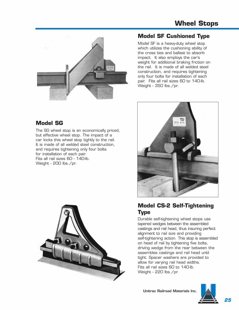
Unitrac Railroad Materials Inc.
Wheel Stops
Model SF Cushioned TypeModel SF is a heavy-duty wheel stopwhich utilizes the cushioning ability ofthe cross ties and ballast to absorbimpact. It also employs the car’sweight for additional braking friction onthe rail. It is made of all welded steelconstruction, and requires tighteningonly four bolts for installation of eachpair. Fits all rail sizes 60 to 140-lb.Weight - 350 lbs./pr.
Model SGThe SG wheel stop is an economically priced,but effective wheel stop. The impact of a car locks this wheel stop tightly to the rail. It is made of all welded steel construction, and requires tightening only four bolts for installation of each pair.Fits all rail sizes 60 - 140-lb.Weight - 200 lbs./pr.
Model CS-2 Self-TighteningTypeDurable self-tightening wheel stops usetapered wedges between the assembledcastings and rail head, thus insuring perfectalignment to rail size and providingself-tightening action. This stop is assembledon head of rail by tightening five bolts,driving wedge from the rear between theassembles castings and rail head untiltight. Spacer washers are provided toallow for varying rail head widths.Fits all rail sizes 60 to 140-lb.Weight - 220 lbs./pr.
25
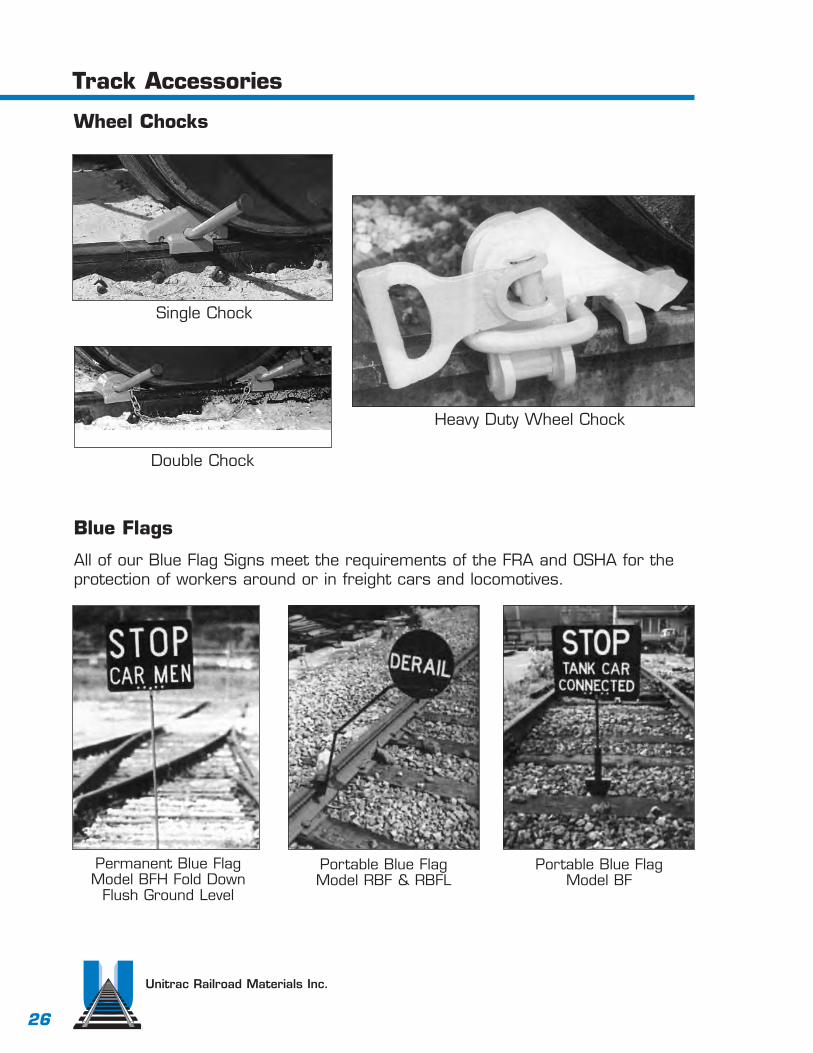
Unitrac Railroad Materials Inc.
26
Track Accessories
Wheel Chocks
Single Chock
Double Chock
Heavy Duty Wheel Chock
Blue Flags
Permanent Blue FlagModel BFH Fold Down
Flush Ground Level
Portable Blue FlagModel RBF & RBFL
Portable Blue FlagModel BF
All of our Blue Flag Signs meet the requirements of the FRA and OSHA for theprotection of workers around or in freight cars and locomotives.

Unitrac Railroad Materials Inc.
27
Derails
Model HB Derail & StandThis is a heavy duty design, which slides onand off the rail.
Operating stand must be ordered separately.
When ordering specify Right-hand, Left-hand,or double-end. Also specify rail section beingused.
Model EB Derail & Blue FlagThis is a lighter duty design that flipson and off the rail by hand.Optional accessories include a blueflag or a target stand that indicatethe position of derail.
Model TS Portable DerailThis is a light duty design that is easy to installwith no special tools required. Advisable wherea permanent derail is not practical.
Comes complete with blue flag and is availablein right, left, or double end.

Unitrac Railroad Materials Inc.
28
Rerailers
Model DWThe DW rerailer has a long, low-profile, two-sideddesign, ideal for a wide variety of equipment.With the DW, it is possible to engage derailedwheels farther from the rails than with most otherdesigns, and wheels can be retracked from eitherone side or both sides. Placed with the exclusive“tie cleats” firmly against the first open tie aheadof the derailed wheels, the dual action lockingwedge is driven into the front of the rerailers.The wedge prevents both sliding and tipping.The only tool required for installation is a hammer.Blocking may be necessary.
SPECIFICATIONS* DW-5 DW-51/2
Load Capacity: tons 100 200Weight Each: lbs. (kgs) 180 (82) 172 (78)For Use on Rails: lbs. (kgs) 70 to 100 85 to 140
(35 to 50) (42 to 70)*Specifications subject to change without notice.
Model SWThe SW rerailer can be spiked to the tie orclamped to the rail with an optional wedge-typelocking system.† Either way, the SW is easily andquickly installed for general use to retrack all typesof locomotives and cars smoothly and efficiently.The SW like all of the rerailers, is cast in a specialductile alloy. Lugs on the underside of the unitsprevent sliding past the first tie.
SPECIFICATIONS* SW-A SW-BLoad Capacity: tons 100 200Weight Each: lbs. (kgs) 121 (55) 63 (74)For Use on Rails: lbs. (kgs) 85 to 100 110 to 140
(42 to 50) (55 to 70)
†Model SW-C: Optional Clamp for A & B, 27 lbs./each*Specifications subject to change without notice.
Model CWThe model CW rerailer is designed specifically for mine,quarry, and industrial applications. Used in pairs, right andleft, the special guide groove design permits retracking wheelsfrom either or both sides simultaneously. A steel cam tightensand locks against the rail head as the car wheel tries to pushthe rerailer. This unit works efficiently even with unusually highor badly worn wheel flanges.
SPECIFICATIONS* CW-3 CW-31/2
Load Capacity: tons 15 20Weight Each: lbs. (kgs) 50 (23) 66 (30)For Use on Rails: lbs. (kgs) 30 to 60 40 to 80
(15 to 30) (20 to 40)*Specifications subject to change without notice.

Unitrac Railroad Materials Inc.
29
Ties
New and Relay Ties
Tie Plugs
Switch Ties
6” x 8” – 8’-6’7” x 9” – 8’-6’
500 per Bundle
9’ 91/2’ 10’ 101/2’ 11’ 111/2’ 12’ 121/2’ 13’ 131/2’ 14’ 141/2’ 15’ 151/2’ 16’ 161/2’
5 11’0” 3’-61/2” 42’-61/2” 4 6 3 3 2 1 2 1 2 1 1 2 3 2 2 2 37 2352 60’-11”
6 11’0” 3’-9” 47’-6” 4 6 3 3 2 3 2 1 2 1 2 2 3 3 2 2 41 2628 69’-8”
7 16’6” 4’-81/2” 62’-1” 7 9 4 3 3 3 2 1 2 2 2 2 4 3 3 2 52 3263 88’-0”
8 16’6” 5’-1” 68’-0” 7 9 4 3 3 4 2 1 3 2 3 2 5 3 3 3 57 3630 97’-8”
9 16’6” 6’-41/2” 72’-31/2” 7 9 4 4 3 4 3 3 3 3 2 3 5 3 3 4 63 4041 105’-8”
10 16’6” 6’-5” 78’-9” 7 10 5 4 4 4 3 3 3 3 3 3 4 4 4 4 68 4360 115’-11”
11 22’0” 7’-0” 91’-101/4” 10 10 7 4 5 5 3 4 4 3 3 3 5 5 3 4 78 4935 132’-9”
12 22’0” 7’-91/2” 96’-8” 10 10 7 5 5 5 4 4 4 3 4 3 6 5 4 4 83 5289 141’-4”
14 22’0” 8’-71/2” 107’-03/4” 10 10 7 6 7 6 4 4 5 4 4 5 6 6 5 5 94 6064 159’-2”
15 30’0” 9’-5” 126’-41/2” 15 12 9 8 7 6 5 5 5 5 4 5 6 6 6 6 110 6985 182’-3”
16 30’0” 9’-5” 131’-4” 15 12 9 8 7 6 6 7 5 6 5 4 6 6 6 6 114 7232 191’-0”
18 30’0” 11’-01/2”140’-111/2” 15 14 10 9 8 7 5 5 6 6 5 6 7 7 7 7 124 7930 208’-1”
20 30’0” 11’-01/2”151’-111/2” 15 15 11 10 9 6 6 5 7 6 5 7 3 9 7 7 133 8534 226’-7”
Bill of Switch Ties for Turnouts with Straight Switches
Length and Quantities of Ties
Frog
Num
ber
Leng
th o
fSw
itch
Rai
l
Toe
Leng
thto
1/
2”
Pt.
Lead
P.S
.to
1/
2”
Pt.
Qua
ntity
of T
ies
Boa
rdM
easu
re
Trac
k Le
ngth
s of
Cro
ss T
ies
Rep
lace
d

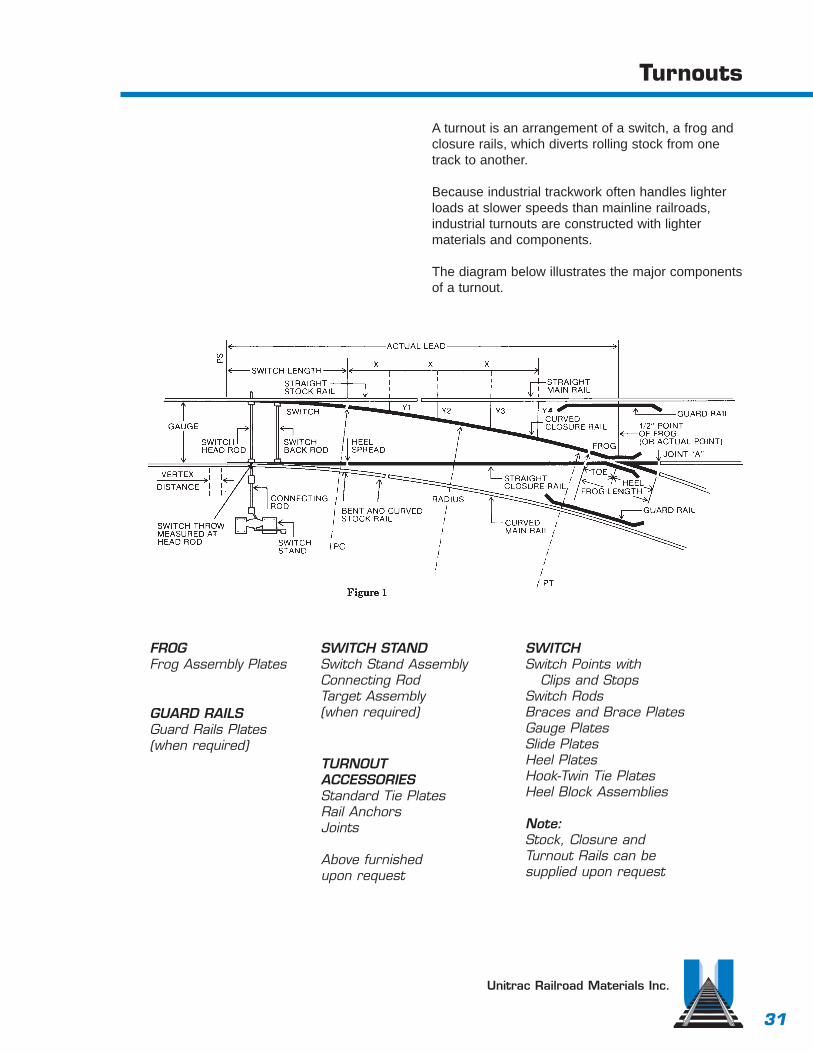
31
Turnouts
A turnout is an arrangement of a switch, a frog andclosure rails, which diverts rolling stock from onetrack to another.
Because industrial trackwork often handles lighterloads at slower speeds than mainline railroads,industrial turnouts are constructed with lighter materials and components.
The diagram below illustrates the major componentsof a turnout.
Unitrac Railroad Materials Inc.
FROGFrog Assembly Plates
GUARD RAILSGuard Rails Plates(when required)
SWITCH STANDSwitch Stand AssemblyConnecting RodTarget Assembly(when required)
TURNOUT ACCESSORIESStandard Tie PlatesRail AnchorsJoints
Above furnished upon request
SWITCH Switch Points with
Clips and Stops Switch RodsBraces and Brace PlatesGauge PlatesSlide PlatesHeel PlatesHook-Twin Tie PlatesHeel Block Assemblies
Note:Stock, Closure andTurnout Rails can be supplied upon request

32
Turnout Installation
Unitrac Railroad Materials Inc.
1. Place turnout material in its approximate location.
2. Establish a string line over the straight switch point through thefrog - Point A to Point B. This establishes the gauge line of thestraight side of the turnout.
3. Place material under the gauge line (string line A-B).
4. Select or locate the Point of Switch, C.
5. Set the straight switch point and the curved stock rail in place.
6. Measure the lead distance and set the 1/2’” point frog, D.
7. Square up the other switch point and stock rail assembly asshown in diagram (Points C, E & F). Note: dimensions will varywith change in gauge.
8. Fill in closure, turnout, and guard rails as required.
9. Assemble joints, but do not tighten.
10. Recheck alignment and square for visual appearance.Are straight lines straight?Are curves smooth?
11. Spike every 4th and 5th tie to decrease movement prior totightening the joints.
12. Now you are ready for final assembly. Tighten the joints andspike the balance of the turnout.
STRAIGHT GAUGE LINE METHOD NOMINAL 56 1/2

33
11’-0” Straight Split Switch
Unitrac Railroad Materials Inc.
16’-6” Straight Split Switch

34
Split Switch with Uniform Risers
The switch rails have a uniform elevation for the entire length of the switch(up 1/4”). Turnout plates have decreasing risers to slope the closure railsback down to the same elevation as the stock rails.
Unitrac Railroad Materials Inc.
PLAN VIEW OF SWITCH AND PLATELAYOUT WITH UNIFORM RISERS
Unitrac produces switches to the following AREA plans:
111 16’-6” Straight Split Switch with Uniform Risers.
113 11’-0” Straight Split Switch with Uniform Risers.
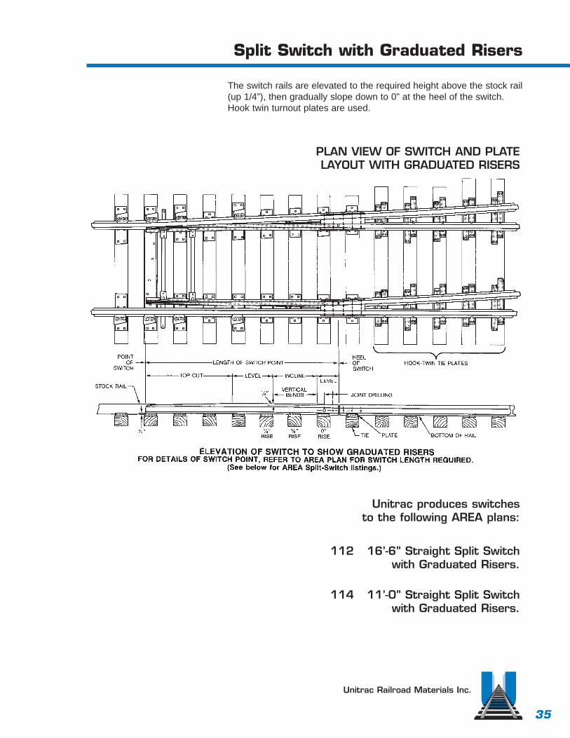
35
Split Switch with Graduated Risers
The switch rails are elevated to the required height above the stock rail(up 1/4”), then gradually slope down to 0” at the heel of the switch.Hook twin turnout plates are used.
Unitrac Railroad Materials Inc.
PLAN VIEW OF SWITCH AND PLATELAYOUT WITH GRADUATED RISERS
Unitrac produces switches to the following AREA plans:
112 16’-6” Straight Split Switch with Graduated Risers.
114 11’-0” Straight Split Switch with Graduated Risers.

36
Frogs
Frogs permit wheel flanges to cross opposing rails in turnouts and crossings, while providing support for the wheels. The end of the frog nearest the switch is the toe of the frog, the other end is the heel.
Frogs are referenced by angle which is converted to a number.For example, a number 8 frog creates an angle of 7 degrees 9 minutes and 10 seconds or an angle of 1-8. To put it more simply,for every increase of 8” on the gauge line, the spread or distancebetween gauge lines increases 1”
Unitrac Railroad Materials Inc.
HOW TO DETERMINE FROGNUMBER FOR STRAIGHT FROGS ONLY
METHOD 1
The frog number is the ratio of its length to its width.
Formula (all dimensions in inches)
Total frog length
Gauge line Gauge line toe spread heel spread
Example: For an AREA 623, No. 10:
16ft. 6 in. 198 in.
7 3/16 ÷12 5/8 19 13/16 in.
÷= Frog Number
= 10=
METHOD 2
The frog number is the ratio of itslength to spread in the heel section ofthe frog.
Step1. Measure the spread at any pointon the heel. Mark the gauge line, A.
Step.2. Mark a second gauge line, B,where the spread is one inch greater than at A.
Step 3. Measure the distance, C, fromA to B to get the frog number.
ExampleSpread A = 5 in.Spread B = 6 in.Distance C =10 in.Therefore, the frog is a No. 10

37
A.R.E.A Frogs
Unitrac Railroad Materials Inc.
BOLTED RIGID FROG
A low relative cost frog recommended for yard and other medium speed applications where heavy duty performance is not required.
RAILBOUND MANGANESE FROG
Railbound manganese frogs are recommended for main lineturnouts and crossovers subject to high speed and heavy traffic.By using manganese steel in the critical areas this design pro-vides high resistance to wear and impact.These frogs can be furnished explosion and/or high integrityhardened upon request.
SOLID MANGANESE SELF-GUARDED FROG
This one piece manganese self-guarded frog is recommended forlocations subject to heavy traffic and slow speeds.
• Standard rail lengths and hook twin tie plate quantities are in accordance with latest A.R.E.A. recommended practices or as specifiedby purchaser.

38
Hook Twin Tie Plates for Frogs
TYPICAL APPLICATIONS OF HOOK-TWIN TIEPLATES. Refer to AREA frog plans for requiredquantities of plates.
Frog design, frog size and type of connectingrails will determine the quantity of hook-twin tieplates required. Connecting rail types are listedat right.
Unitrac Railroad Materials Inc.
TYPE I Rail - Rails having base up to 5 3/16” and head 2 9/16” inclusive
TYPE II Rail - Rails having base up to 5 1/2” and head 2 3/4” inclusive
TYPE III Rail - Rails having base up to 6” and head 3” inclusive

39
Hook Twin Tie Plates
Unitrac Railroad Materials Inc.
Unitrac hook twin tie plates aremade in accordance with AREAPlan. 241 for use under frogs,and beyond the heel where stan-dard tie plates cannot be placedwithout cutting. Quantities to befurnished are listed in this cata-log for various units illustrated.Dimensions of several types ofrails are stated below.
TYPE I Rail - Rails having base up to 5 3/16” and head 2 9/16”inclusive
TYPE II Rail - Rails having base up to 5 1/2” and head 2 3/4” inclusive
TYPE III Rail - Rails having base upto 6” and head 3” inclusive

40
Switch Clips and Switch Rods
Unitrac Railroad Materials Inc.
SIDE JAW CLIP
This design is non-adjustable.Jaw opening anddrilling per AREA or customer specifications.
ADJUSTABLE SIDEJAW CLIP
This design can be adjustedin order to maintain desiredspacing between switchpoints. Jaw opening anddrilling per AREA or customer specifications.
TRANSIT CLIP
Design provides for adjustment inorder to maintain desired spacingbetween switch points. Drilling perAREA or customer specifications.
A switch rod is a steel bar that connectsleft-hand and right-hand switch points sothat both points move in unison. Thuswhen one switch point is open, the otheris closed.
Switch rods are sized according to railsection.
A switch usually has one rod that is con-nected to the throwing mechanism orswitch-stand assembly. This rod is calledthe Head Switch Rod or Operation Rod.The other rod is the Back Switch Rod.

41
Switch Points
Unitrac Railroad Materials Inc.
Unitrac Samson switch points and stock rails areused for heavy duty applications where knife-bladepoints may break down.
END VIEW OF SWITCH POINT
CLOSED OPEN
END VIEW OF COMMONSTANDARD KNIFE-BLADE
SWITCH POINT
CHAMFERED DESIGN SAMSON DESIGN STANDARD DESIGN
Knife blade points may be used fornormal track use.

42
Heel Blocks
Unitrac Railroad Materials Inc.
HEEL BLOCK ASSEMBLIES
A heel block is a spacer that maintains the posi-tion of the switch point to the stock rail and clo-sure rail. It is also the pivoting point of theswitch point.
Unitrac can supply heel blocks in various designsincluding welded, cast and floating as shown.Unitrac provides heel blocks with bent andbeveled bars and new bolts with nuts and heavyduty lockwashers. Specify type, rail section,drilling and length of switch when ordering.
FLOATING HEEL BLOCK
Primary used in high speed, long lengthswitch operations.
WELDED HEEL BLOCK ASSEMBLYCAST IRON HEEL BLOCK ASSEMBLY

43
Unitrac Railroad Materials Inc.
Braces are designed to restrain movement of thestock rail when a switch is opened or closed.Unitrac can furnish forged steel rigid braces similarto AREA Plan 223. We can furnish a number ofadjustable brace designs that will fill your mostcommon or unusual requirements. (Available in the811 design or the AREA Plan 224 Type A designas shown below.) Also available is BethlehamSureFit Boltless Adjustable Brace. Available in bothnew and relay, all braces are checked with railprior to shipping to insure a correct fit.
Switch Plates and Braces
Bethleham SureFit Boltless Adjustable Brace
Area Design 224Type A Adjustable Brace
Design 8-11Adjustable Brace
Forged Rigid BracePer Area 223

44
Unitrac Railroad Materials Inc.
Switch Plates and Rigid Rail Braces
Unitrac manufactures a comprehensive range of switch plates and braces for applications, manufactured from steel by fabricationmethods to suit the individual customer requirements.
DETAIL 4103
GAGE PLATE INSULATION
DETAIL 3103
RAIL BRACE–DETAIL 6023

45
Switch Plates
Unitrac Railroad Materials Inc.
Gage PlateMaintains gage at the point of switch.Available either insulated or non-insulated.
Shoulder Slide PlateHolds the stock rail inposition and allows theswitch point to slide asrequired.
Slide Plate with Milled Pocket for Shoulder
Slide Plate with Milled Pocket and Rolled Shoulder
Shoulder Heel PlateFits under the heel block.
Standard Plates forsingle-tie installation
Hook-Twin Tie PlateUsed in graduated-riser applicationsbeyond the heel of aswitch.Fits all switchlengths, rail sections, andturnouts.Most economicalplate to use beyondthe heel of a switch.Available for quickdelivery.
Turnout Pocket PlateUsed in uniform-riser applicationsbeyond the heel of a switch. Assists in maintaining rail gage. Must be manufactured for specificswitch length, rail section andturnout alignment.
A Plate is a section of rolled steel that supports a rail or other track structure. Plates are sized to conform to AREA designs, unless specified otherwise.

46
Guard Rails
A Guard Rail is a rail laid parallel withthe running rails to hold the wheels incorrect alignment. Guard rails preventderailments and protects the points ofturnout frogs, crossing frogs and switchpoints. Unitrac furnishes guard rails inthree basic designs:
Tee-Rail (AREA 504)
Hook- FlangeDesign 750Design 751Design 752
Switch-GuardsModel 755Model 755-GModel FM
Unitrac Railroad Materials Inc.
A panel switch with a 4’-9” Switch Point GuardRail, Model 755, that will prolong the service lifeof the switch point.
In this panelized turnout , two Hook FlangeGuard Rails, Design 751, will protect the pointof the frog from traffic on either side.

47
A.R.E.A. Guard Rails
This guard rail conforms to A.R.E.A. plans and specifications and is fur-nished complete with separator and end blocks, bolts and shoulder tieplates as illustrated.
SETTING OF TEE RAIL GUARD RAILS
• Guard rail flare to be opposite the frog wing rail flare for all angles.• Bolted Rigid & Rail Bound Frogs.The parallel portion of the guard rail
is to extend 15” minimum beyond the the throat.
MINIMUM LENGTH OF GUARD RAILS CONFORMING WITH THE ABOVE SETTINGS
• Bolted rigid & Rail Bound FrogsLength of Guard Rail Frog No’s
13’-0” 8.9 & 1016’-6” 11,12,14 &1520’-0” 16 & 20
Unitrac Railroad Materials Inc.
AREA 504
Guard Rail Tie Plate
Section ThruSeparator Block
Section Thru End Block

48
Hook Flange Guard Rails
Hook-Flange Guard Rails are constructed from custom-rolled rail sections. One flange islowered to fit under the base of the running rail. Compare any of the three Hook-Flangedesigns to conventional T-rail and you’ll see several advantages:
• Selection. Choose from 9’-0”, 11’-0”, 13’-0” and 16’-6” standard length.
• Convenience. All guard rails, tie plates and foot guards are shop assembled. Each units ships in one piece, ready to install.
• Lower Installation Cost. No need to drill holes in the running rail, no need to adzethe ties for the tie plates, and no need for special tools at the job site.
• Stability. Each tie plate spans two or more ties. A shoulder on the guard-rail side ofthe tie plate provides locking against lateral movement.
• Reduced Maintenance. No checks or separator blocks to vibrate loose.
Unitrac Railroad Materials Inc.
Design 750 Design 751 Design 752

49
Switch-Point Guard Rails
Switch-Point Guard Rails protect the switch point, prolong the life ofstock rails, reduce flange cutting, prevent wheel climbing, and help toprevent derailments at the switch.
The guard rail is heat treated for extra long life.
Guard rail, plates, braces and filler blocks are shipped assembled,ready for installation.
No special tools are required at the job site.Switch-Point Guard Rails are practically free of maintenance expense.
Unitrac Railroad Materials Inc.
Model 755-GFurnished with gage plate
Model FM
Model 755 Switch-Point Guard Rail

50
Switch Point Derail
A switch point derail will derail rolling stock in anemergency. Some useful locations may be a sidingleading into a chemical loading area, or if anuncontrolled car can get from a side track onto amain track. Available in 11’ single (as shown below)or in 16’6”. Both are available as a double switchpoint derail. Unitrac can provide these in new, or fullyreconditioned, complete per your bill of materials.
HOW TO ORDERPlease specify (in addition to the usual switch information):
1. Whether switch point is left-hand or right-hand.
2. If stock rail is required, include:a. Length. b. Stagger. c. Joint drilling.
TYPICAL LAYOUT11’0” SWITCH FOR RIGHT-HAND TURNOUT FOR ILLUSTRATION ONLY. CAN BE FURNISHED TO CUSTOMER’S DESIRED LENGTH, ALIGNMENT AND ACCESSORIES.
Unitrac Railroad Materials Inc.

51
Unitrac Railroad Materials Inc.
Switch Stands and Components
MODELS 50 AND MODELS 51
Model 51 stands are available in the low profile (Model 51A and inter-mediate profile (Model 51B). Rugged construction, ease of operation,and nearly a century of proven reliability makes the Switch Stands anexcellent choice for use on main lines, sidings, and yard tracks.
Switch Stands are made in two designs: Model 50 (non-adjustable) and Model 51 (adjustable).
In the Model 50, the switch adjustment is made at the connecting rod.
In the Model 51, there is a convenient, selective adjustment feature. By the use of shims in the adjustment slot, either switch point may be adjusted independently of each other.
Switch Stands Models 50 and 51 are made in two types – low andintermediate. The low type distinguished by the letter “A” following the model number; the intermediate type by the letter “B” after thenumber.
Switch Stand Model 51-A
Low Switch Stand Model 50-A
IntermediateSwitch Stand Model 50-B

52
Switch Stands
Unitrac Railroad Materials Inc.
MODEL 51
Model 51 stands are available in the low type(model 51A) and intermediate (model 51B).Rugged construction and ease of operationmake them an excellent choice for use onmain lines, sidings, and yard tracks.
Switch points can be adjusted independentlyof each other by use of shims(see drawing).The weighted throw lever assures positiveclosing of the switches when engaged withthe foot latches.
Plug Lamp Tip
Lamp Tip Bolt
Segment tube
Adjustment Shims
Adjustment Bolt
Top
Segment Gear
Spindle Lug
Throwing Lever
Cover Bolt
Oil Holes
Pinion Shaft
Pinion Gear
Bottom
Drain Hole
Crank Pin
Crank
Cross Pin/Ring
Model 51-B

53
Switch Stands
Unitrac Railroad Materials Inc.
Model 51-A(with housing removed)
New and reconditionedparts available
Adjustment Shims
Adjustment Shims
Storage Space

54
Switch Stands
Unitrac Railroad Materials Inc.
MODEL 22
Model 22 is an ideal switch stand for busyyard and ladder locations where the switchstand is likely to be run through. When theswitch is run through, the flange of the wheelpartially opens the switch points and then aninternal spring takes over and completes thethrow. This prevents damage to the switchstructure that will occur during a run throughon stands that do not have this trailing feature. Also, as an added safety feature, the change of position of the points occurswithout the handle of the switch stand evermoving. Available new or fully recondition,with or without rod and target.
MODEL 112E
The Model 112E switch stand is asturdy, high parallel throw, two tiestand. You can adjust your throw byturning the forged steel crank eyethus assuring proper setting of theswitch points.
This design is simple, rugged, easilyinspected and ideal for mainline applications. Available new orreconditioned, with or without rodand target.

55
Switch Stands
Unitrac Railroad Materials Inc.
Models 22-E & 22-EH
Model 22-HE
The Model 22-E and 22-EH are ergonomically engineered, extra-heavy-duty trailable switch stands. The lowstand 22-E is for yard, ladder and busyswitch turnouts, where trains often runthrough switches. The 22-EH is con-structed of identical base housing andoperating parts, but features a high mastand target, providing increases visibilitywhere needed.
Ergonomic Design for Operator SafetyThe distinct “ triangular hand lever has agrasp point that is 30” above ground,helping to prevent painful bending and lift-ing. Also, the typical 180º movement forthe lever has been reduced to 125º, sothe switch can be thrown with minimaloperator motion. Together, theseergonomically engineered features willhelp to assure safety for the operator.
Automatic Operation for Accidental TrailingThe Models 22-E and 22-EH can betrailed or thrown manually. When a trainruns through the switch, switch pointsare partially opened by the wheel flanges,and the throw is completed automatically.During automatic trailing, the target lamprotates so that the switch point positionis indicated, while the hand lever remainsstationary.
Both models eliminate expensive repairsto stand, track and derailed equipmentthat result when a train runs through theswitch with a rigid stand. An adjustableconnecting rod and crank eye permitaccurate setting of the points withoutrespiking the stand.
Quality Components and ConstructionThe 22-E and 22-EH feature high qualitycomponents and construction, includingextra heavy cast iron housings, as well asheat-treated working parts and oversizedcrank eye forged from SAE specificationsteel. The extra large bearing surfaces ofthe few wearing parts assure long lifeand a minimum of lost motion.

56
Stand Components
Unitrac Railroad MaterialsInc.
Flat Top SSN 290For use on models 50-B, 51-A & 51-B Made of cast iron.
Forged CrankSSN 251
Adjustable Shim Set SSN 210For use on models 51-A,51-B
Cover SSN 200For use on models 51-A & 51-B. Madeof malleable iron.
Breakable CrankSSN 250
SSN 220For use on SwitchStands. Made offorged steel.
Ring SSN 994 This ring servesas a lock forcross pin.
Cross Pin SSN 994Special Shear-resistantsteel.
Adjustment BoltSSN 996For use onModels 51-A and 51-B
Adjustable GearSegment SSN 300For use on Model 51-A.Made of malleable iron.
Latch Stand SSN 230For use on all switch stands.
Bottom SSN 295For use on all SwitchStands. Wide, heavybase of cast iron.
Bow HandleSSN 223For use on all Switch Stands. Optional colors available.
Top ExtensionSSN 292For mast support onswitch stand models50-B and 51-B
Throwing LeverSSN 225A rolled steel lever, assembledwith pinion gear for Models 50and 51. 30 pound cast ironweighted handle.

57
Stand Components
Unitrac Railroad Materials Inc.
Plug Lamp Tip SSN 270For use with low stands. The plug lamptip fits directly into the segment tube ontop of the stand and takes the place ofthe usual target mast. The target usedis correspondingly low.
Socket Lamp Tip SSN 270For use over the mast on low or intermediate stands. The socket end fits over the top of the mast.
Targets for 51-A SSN 240
Connecting Rods for 51-A SSN 260
Model 11AN
Model 11TN
Target Masts SSN 280For Low Models 50-A and 51-A.
Length:1’ 05/8”
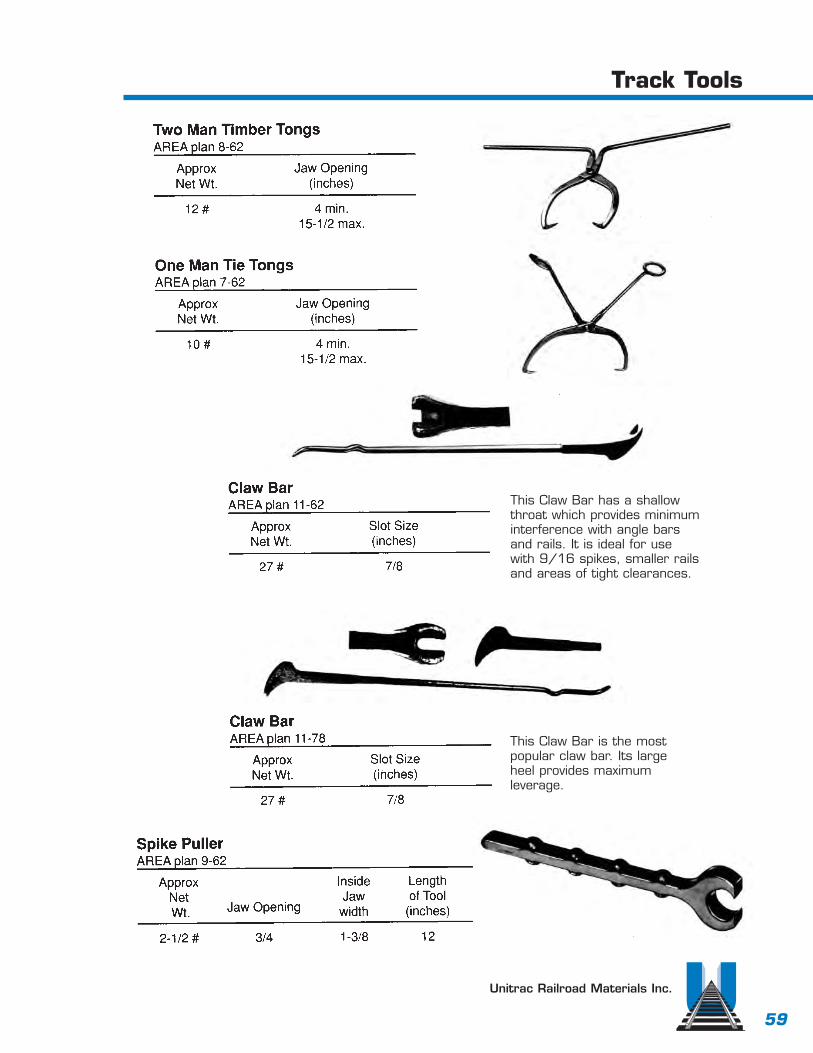
Unitrac Railroad Materials Inc.
Track Tools
59
This Claw Bar has a shallowthroat which provides minimuminterference with angle bars and rails. It is ideal for use with 9/16 spikes, smaller railsand areas of tight clearances.
This Claw Bar is the mostpopular claw bar. Its largeheel provides maximumleverage.
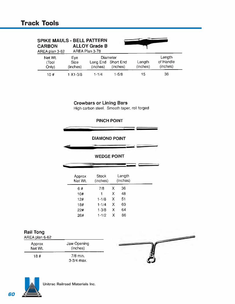
Unitrac Railroad Materials Inc.
Track Tools
60

Unitrac Railroad Materials Inc.
Track Tools
61

TS-1, TS-2, and TS-3 cartsConvenience, durability and a 5,000 lb. load capacity have made Tool and Supply Carts anindustry standard. Easily handled by one person,the two-piece design merely “fits together” andlocks securely. No screws, bolts or straps arerequired. Together, the sections form a large 46” x 45” heavy duty expanded metal deck. High carbon tubular steel forms the frame assembly. The push handle is removable andstake pockets provide for containment of deck area materials. The whole package is field provento assure years of maintenance-of-way service.
Tool & Supply Carts
Rail TongDesigned to pick up rail be either base orhead, the anti slip gripping power canhandle 39’ lengths of rail up to 150 lbs.per yard. Weight 60 lbs. each.
Cribbing BucketCustom made for back hoes
Unitrac Railroad Materials Inc.
Track Tools
62

Unitrac Railroad Materials Inc.
Track Tools
63
Track Tools
Rail Benders
Track Jacks
Bender Assemblies
Mechanical Track Jacks

Unitrac Railroad Materials Inc.
Track Tools
64
No. 2 Aluminum Track LevelConstructed of extruded, anodized aluminum tubing with cast aluminum ends. A guard rail spacer lug is built into one end casting. Elevation scale offers 0” - 7” readout in 1/8” incre-ments. Scale can be locked at any setting, and slides inside of tube when not in use. Level has adjustable, (A.R.E.A. approved) vial assembly. Level is fully insulated. Weight - 5 lbs.
No. 3 Aluminum Track GageConstructed of the same durable materials as the No. 2 Track level, the No. 3 Gage features a rail stop end fitting provided with guard rail spacer lug, and recessed slots on gage fitting topermit accurate gaging of even heavily runover rail. Track Gage is fully insulated. Weight - 6 lbs.
No. PG-2 Steel Pipe Track GageSchedule 80 pipe center is strong enough to act as a bridge and permit one rail to be forcedinto gage with the other. Gage is measured 5/8” below top of rail head, as per A.R.E.A.requirements. One end casting has guard rail spacer lug. Product is completely insulated.Weight - 18 lbs.
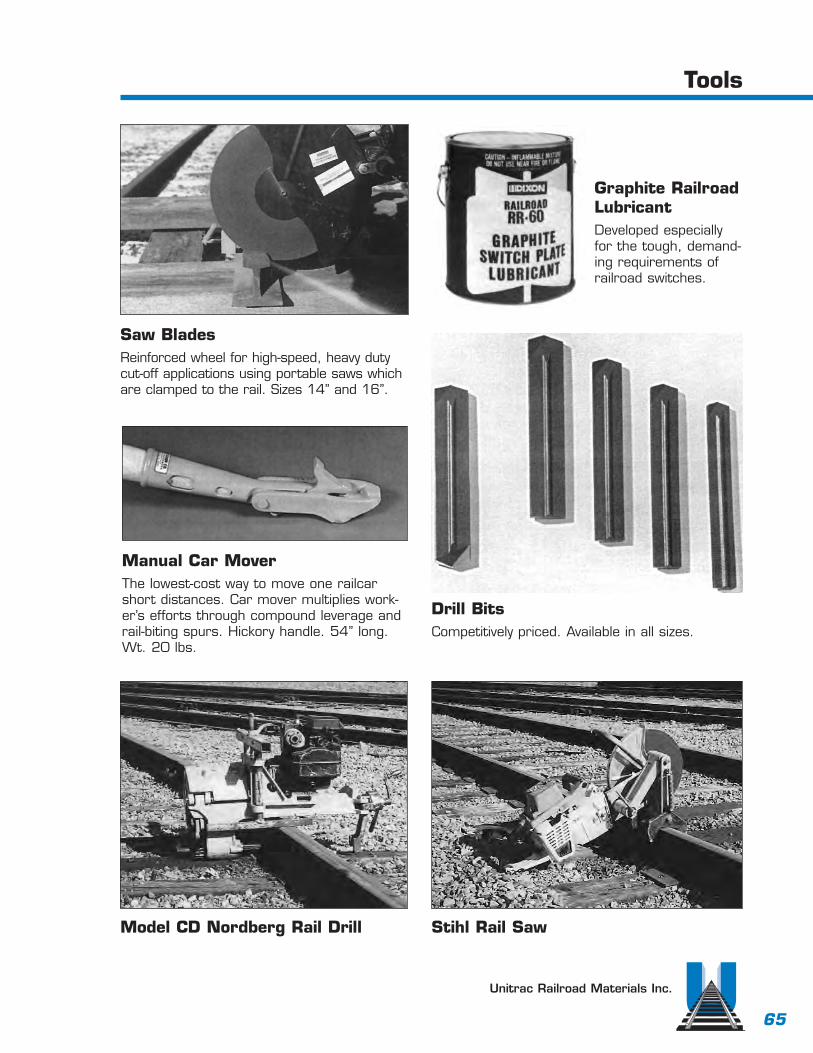
Unitrac Railroad Materials Inc.
Tools
65
Model CD Nordberg Rail Drill
Drill BitsCompetitively priced. Available in all sizes.
Manual Car MoverThe lowest-cost way to move one railcarshort distances. Car mover multiplies work-er’s efforts through compound leverage andrail-biting spurs. Hickory handle. 54” long.Wt. 20 lbs.
Saw BladesReinforced wheel for high-speed, heavy dutycut-off applications using portable saws whichare clamped to the rail. Sizes 14” and 16”.
Stihl Rail Saw
Graphite RailroadLubricantDeveloped especiallyfor the tough, demand-ing requirements ofrailroad switches.

Pannelized TurnoutsUnitrac is equipped and ready to pannelizeany turnout to your specifications.
Field WeldsUnitrac is equipped to do field welds.We are qualified in both Thermiteand Boutet type.
Unitrac Railroad Materials Inc.
Field Services
67

Unitrac Railroad Materials Inc.
Field Services
68
Welding Frogs Welding Switch Points
AbandonmentsUnitrac purchasestrack abandonmentsof any size. Our expe-rienced personnelcan remove rapidlyand safely.

Unitrac Railroad Materials Inc.
71
General Information & Terms

Unitrac Railroad Materials Inc.
72
General Information & Terms

Unitrac Railroad Materials Inc.
Decimal & Metric Equivalents of Common Fractions of an Inch
73

Unitrac Railroad Materials Inc.
74
Metric & English Conversion Table

Unitrac Railroad Materials Inc.
75
Middle Ordinates in InchesFor Railroad Curves


Read
ing
Blue
Mou
ntai
n an
d No
rther
n Ra
ilroa
dEn
gine
erin
g an
d In
dust
rial D
evel
opm
ent D
epar
tmen
t
Priv
ate
Cros
sing
Tra�
c W
arni
ng A
ppar
atus
RBM
N P
LAN
# _
-_ _
_
NO
TES:
TO B
E PL
ACES
AT
ALL
CRO
SSIN
GS
NO
T AC
CES-
SIBL
E O
R O
PEN
TO
TH
E G
ENER
AL
PUBL
IC
PRIV
ATE
CRO
SSIN
GSI
GN
TO
BE
3290
SIL
VER3
M
HIG
H IN
TESI
TY G
RAD
E BA
CKG
ROU
ND
ON
.080
” SH
EET
ALU
MIN
UM
SIG
N L
OCA
TIO
N S
HO
ULD
BE
10’ F
ROM
TH
E N
EARE
ST R
AIL
AN
D 1
0’ H
IGH
CEN
TER
OF
POST
8’ (
2.4M
) FRO
M T
HE
EDG
E O
F TH
E TR
AVEL
ED R
OA
DW
AY
INST
ALL
SIG
N T
O P
ROVI
DE
THE
BEST
VIE
W F
ROM
TH
E RO
AD
WAY
APP
ROAC
H

Reading Blue Mountain and Northern RailroadEngineering and Industrial Development Department
Full Depth Concrete Base Options
RBMN PLAN # _-_ _ _

Reading Blue Mountain and Northern RailroadEngineering and Industrial Development Department
Full Depth Concrete Base Options (Continued)
RBMN PLAN # _-_ _ _

Reading Blue Mountain and Northern RailroadEngineering and Industrial Development Department
Typical full depth concrete crossing
RBMN PLAN # _-_ _ _

Reading Blue Mountain and Northern RailroadEngineering and Industrial Development Department
Detailed Drawing for RBMN typical full depth concrete crossing
RBMN PLAN # _-_ _ _
15:1*15:1*
* Highway approaches are 20:1and Industry approaches are 15:1

NOTES: •The above section should only serve as a guide to minimun specifications.
•Any deviation from this guideline shall be approved by the RBMN in writing.
•Each approach to crossing shall consist of ten new 7” x 9’ x 10’ ties.
Reading Blue Mountain and Northern RailroadEngineering and Industrial Development Department
Concrete Panel Crossing Specification9-0” Lagtype concrete crossing on 10’-0” crosstie with attached filler
RBMN PLAN # 30-11
10'
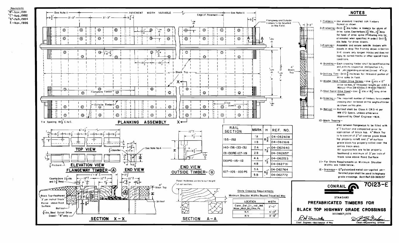

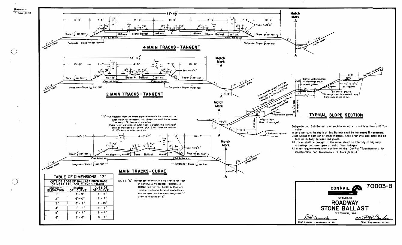


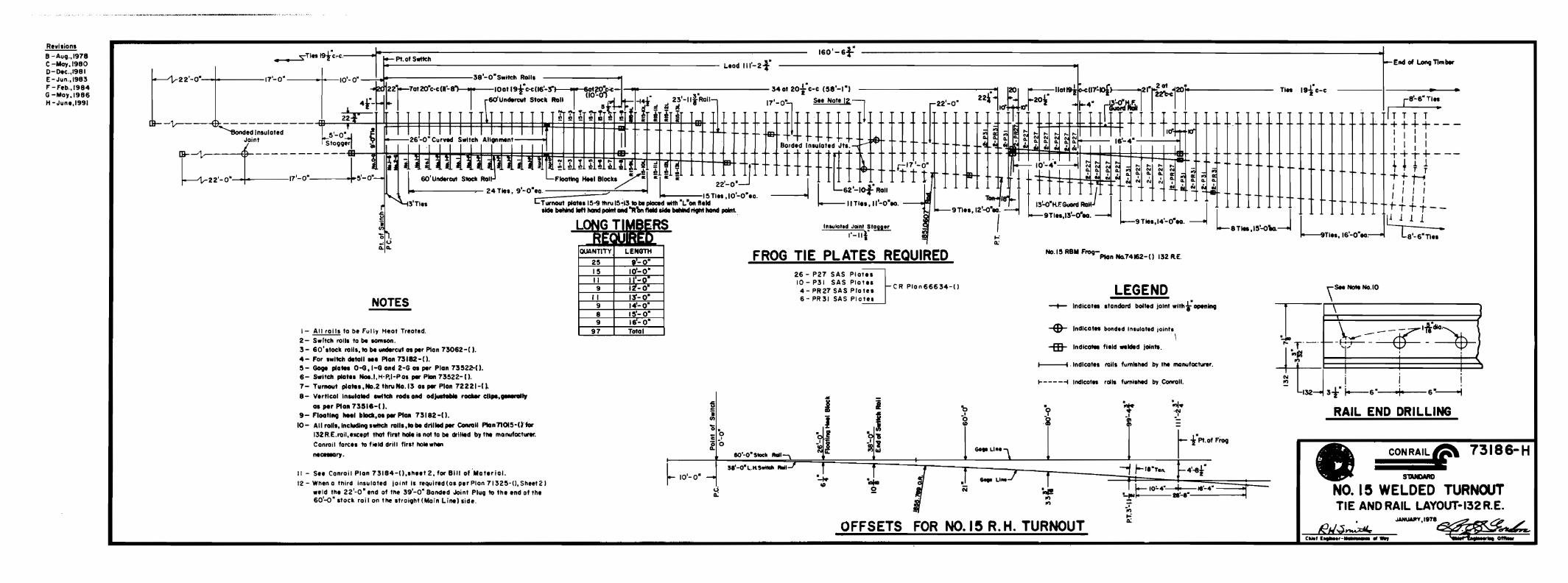

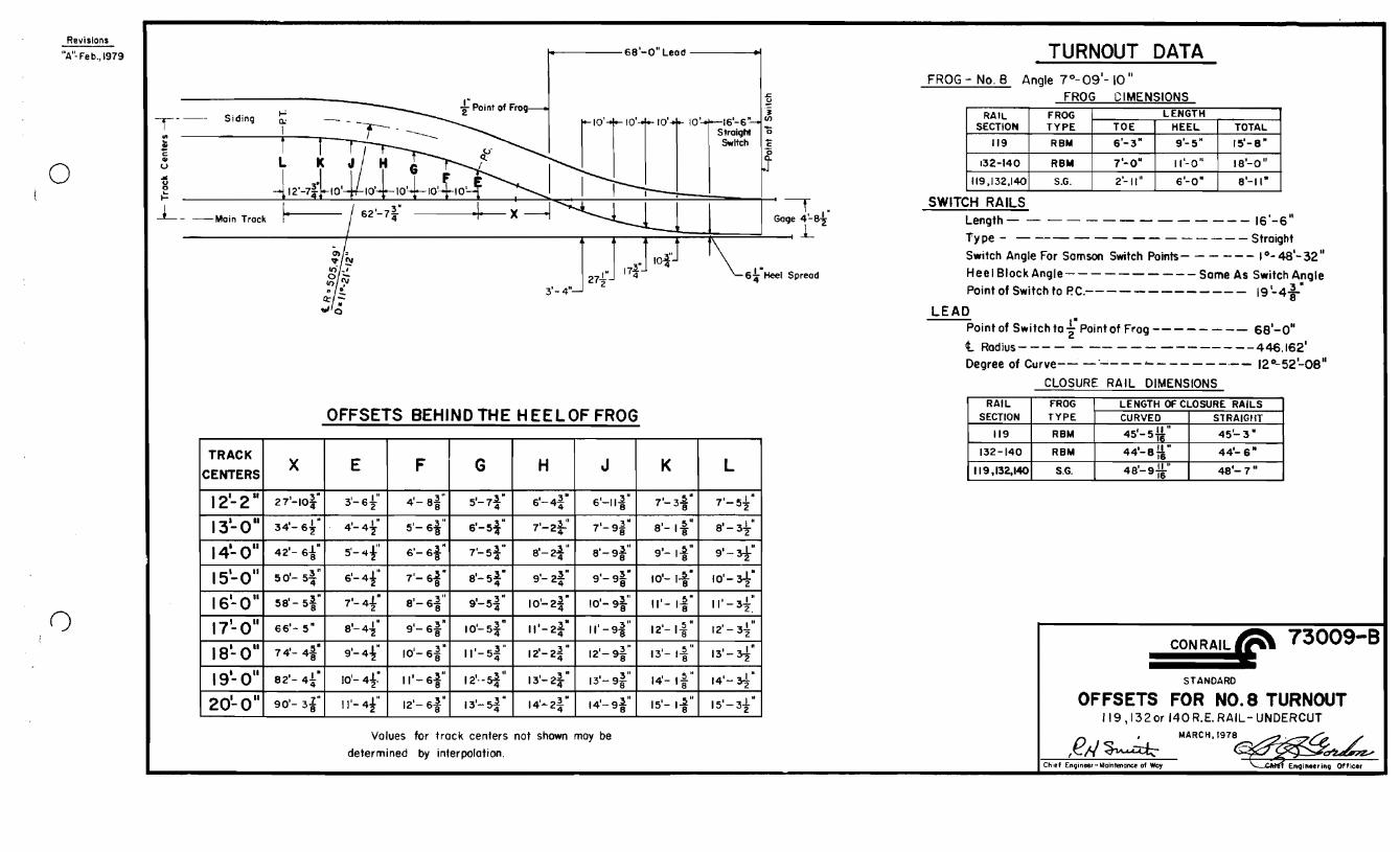

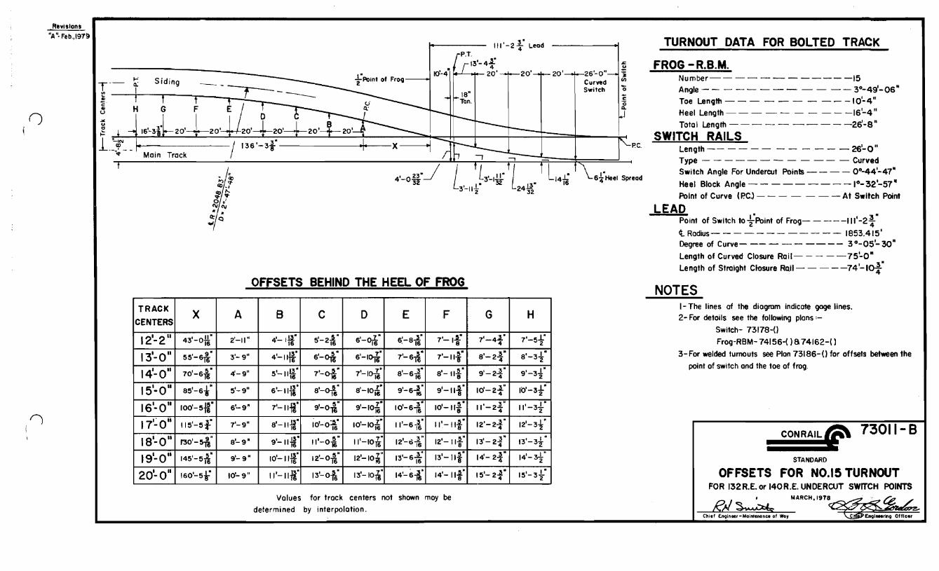


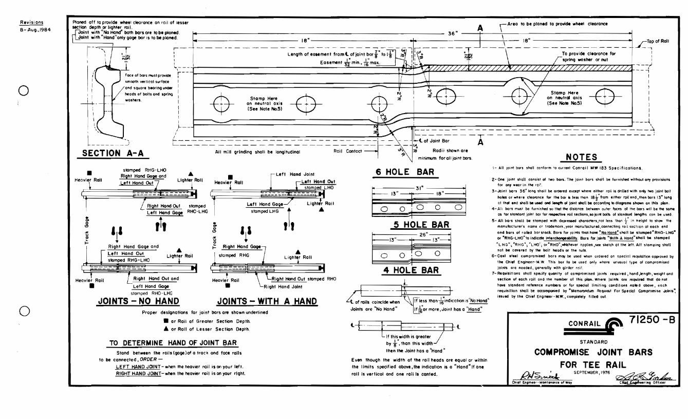


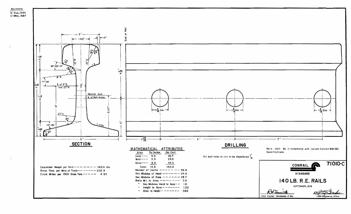

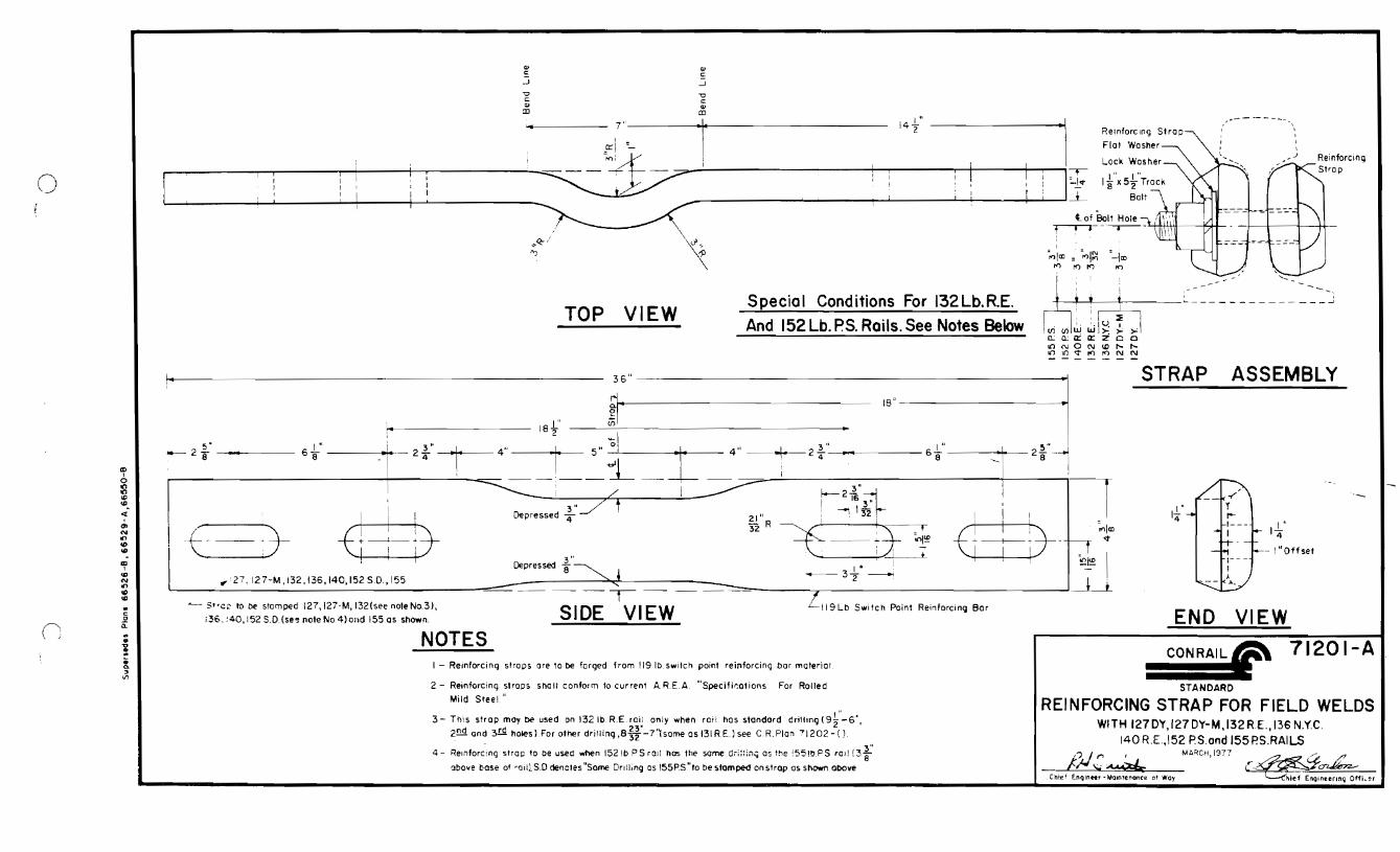


6.625” +.125-.000
1.031±.031
Reading Blue Mountain and Northern RailroadEngineering and Industrial Development Department
136LV Standard Rail Anchor Speci�cations


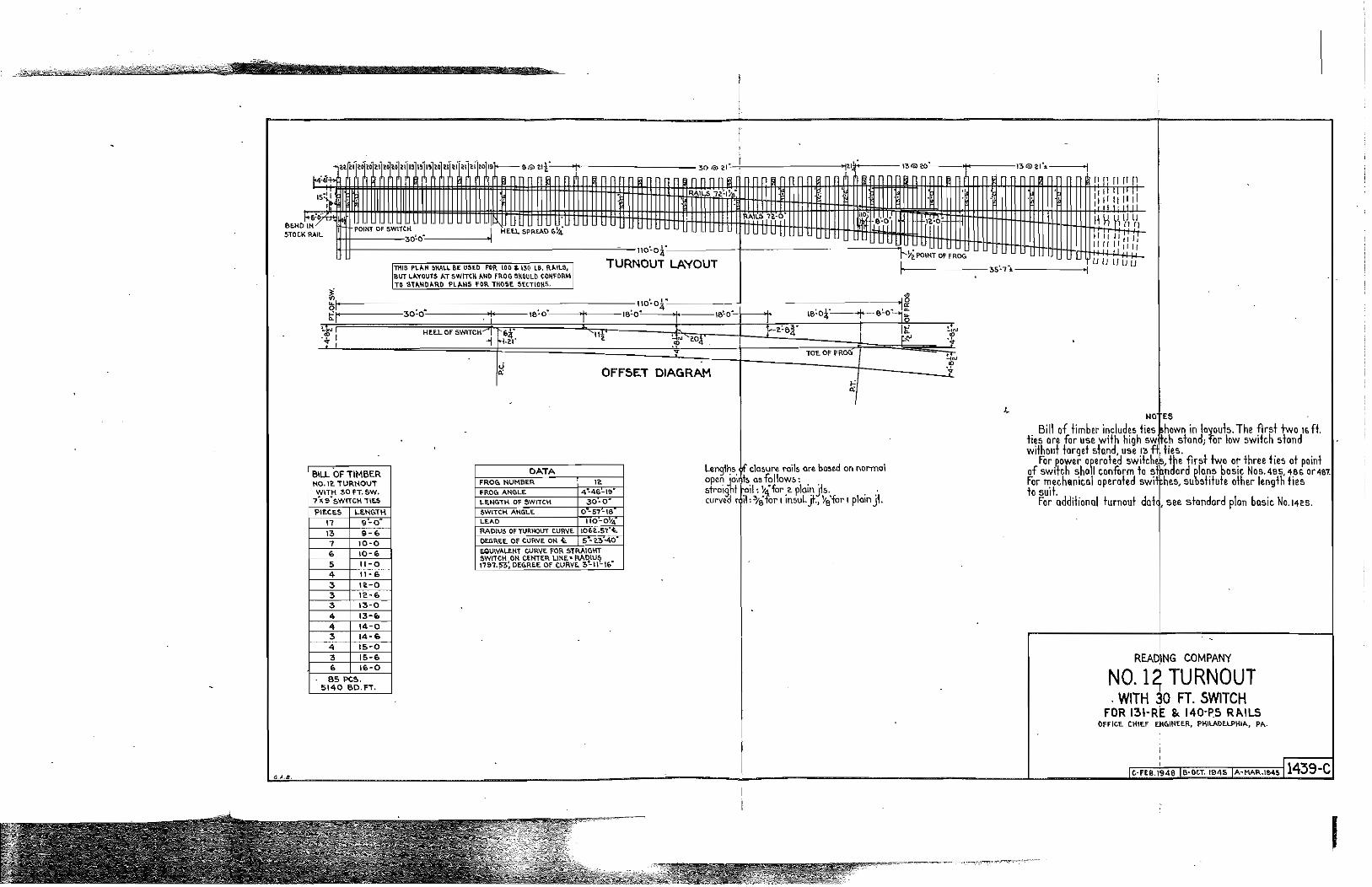


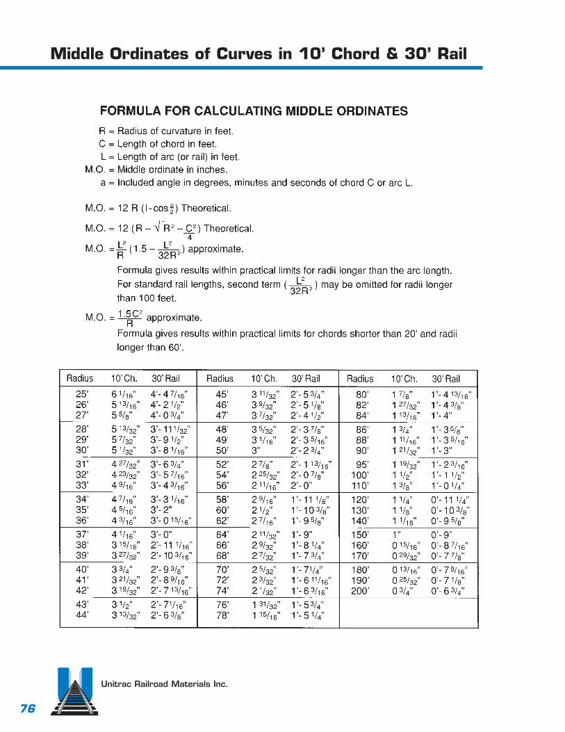
Unitrac Railroad Materials Inc.
76
Middle Ordinates of Curves in 10’ Chord & 30’ Rail