Embed Size (px)
Citation preview
MANUAL
© 2001 CURTIS INSTRUMENTS, INC.
DESIGN OF CURTIS PMC 1200 SERIESCONTROLLERS PROTECTED BY U.S.PATENT NO. 4626750.
1 2 9 7MO
DE
L
INTEGRATED TRACTION& HYDRAULIC SYSTEMC O N T R O L L E R
CURTIS PMC
235 East Airway BoulevardLivermore, California 94550 USATel: 925-961-1088Fax: 925-961-1099www.curtisinst.com
1297 Manual, p/n 36411Rev. A: February 2001
1297 Manualp/n 36411, Rev. A: February 2001
© 2001 CURTIS INSTRUMENTS, INC.
CURTIS INSTRUMENTS, INC.200 KISCO AVENUE
MOUNT KISCO, NEW YORK 10549 U.S.A. 914-666-2971 FAX 914-666-2188
CURTIS PMC235 EAST AIRWAY BOULEVARD
LIVERMORE, CALIFORNIA 94550 U.S.A. 925-961-1088 FAX 925-961-1099
ADDITIONAL OFFICES located inBulgaria, China, England, France, Germany,
India, Italy, Japan, Netherlands, PuertoRico, Russia, Sweden, and Switzerland
www.curtisinst.com
Curtis PMC 1297 Manual iii
1234567890112345678901123456789011234567890112345678901123456789011234567890112345678901123456789011234567890112345678901123456789011234567890112345678901123456789011234567890112345678901123456789011234567890112345678901123456789011234567890112345678901123456789011234567890112345678901123456789011234567890112345678901123456789011234567890112345678901123456789011234567890112345678901123456789011234567890112345678901123456789011234567890112345678901123456789011234567890112345678901123456789011234567890112345678901123456789011234567890112345678901123456789011234567890112345678901123456789011234567890112345678901123456789011234567890112345678901123456789011234567890112345678901123456789011234567890112345678901123456789011234567890112345678901123456789011234567890112345678901123456789011234567890112345678901123456789011234567890112345678901123456789011234567890112345678901123456789011234567890112345678901123456789011234567890112345678901123456789011234567890112345678901123456789011234567890112345678901123456789011234567890112345678901123456789011234567890112345678901123456789011234567890112345678901123456789011234567890112345678901123456789011234567890112345678901123456789011234567890112345678901123456789011234567890112345678901123456789011234567890112345678901123456789011234567890112345678901123456789011234567890112345678901123456789011234567890112345678901123456789011234567890112345678901123456789011234567890112345678901123456789011234567890112345678901123456789011234567890112345678901123456789011234567890112345678901123456789011234567890112345678901123456789011234567890112345678901123456789011234567890112345678901123456789011234567890112345678901123456789011234567890112345678901123456789011234567890112345678901123456789011234567890112345678901123456789011234567890112345678901123456789011234567890112345678901123456789011234567890112345678901123456789011234567890112345678901
CONTENTS
1. OVERVIEW ............................................................................. 1
2. INSTALLATION AND WIRING ........................................... 4Mounting the Controller .................................................... 4Connections: Low Current ................................................ 6Connections: High Current ............................................... 7Wiring: Standard Configuration, without multiplexer ....... 8Wiring: Standard Configuration, with multiplexer .......... 10Wiring: Throttles ............................................................. 12
5kΩ–0 two-wire resistive throttle (“Type 1”) ............. 13Single-ended 0–5V, current source, 3-wire pot,
and electronic throttles (“Type 2”) ..................... 130–5kΩ two-wire resistive throttle (“Type 3”) ............. 17Wigwag-style 0–5V and 3-wire pot
throttles (“Type 4”) ............................................ 17Wiring: Auxiliary Driver .................................................. 18Wiring: Coast and Pick ................................................... 18Wiring: Emergency Reverse ............................................. 18Wiring: Emergency Reverse Check .................................. 18Wiring: Spyglass Display.................................................. 19Contactor, Switches, and Other Hardware........................ 20
3. PROGRAMMABLE PARAMETERS(A: Traction / B: Hydraulic / C: Shared) ................................. 22
3A Traction Parameters .............................................................. 24Acceleration Parameters .................................................... 24
Drive Current Limit, M1–M2 ................................... 24Acceleration Rate, M1–M2 ........................................ 24Current Ratio ............................................................. 25Boost Enable .............................................................. 25
Braking Parameters ........................................................... 25Braking Current Limit, M1–M2 ................................ 25Braking Rate, M1–M2 ............................................... 26Deceleration Rate, M1–M2 ....................................... 26Coast Deceleration Rate ............................................. 26Taper Rate .................................................................. 26Throttle Deceleration Rate ......................................... 26Interlock Braking Current Limit ................................ 27Interlock Braking Rate ............................................... 27Interlock Braking Delay ............................................. 27
CONTENTS
Curtis PMC 1297 Manual iv
CONTENTS
12345678901123456789011234567890112345678901123456789011234567890112345678901123456789011234567890112345678901123456789011234567890112345678901123456789011234567890112345678901123456789011234567890112345678901123456789011234567890112345678901123456789011234567890112345678901123456789011234567890112345678901123456789011234567890112345678901123456789011234567890112345678901123456789011234567890112345678901123456789011234567890112345678901123456789011234567890112345678901123456789011234567890112345678901123456789011234567890112345678901123456789011234567890112345678901123456789011234567890112345678901123456789011234567890112345678901123456789011234567890112345678901123456789011234567890112345678901123456789011234567890112345678901123456789011234567890112345678901123456789011234567890112345678901123456789011234567890112345678901123456789011234567890112345678901123456789011234567890112345678901123456789011234567890112345678901123456789011234567890112345678901123456789011234567890112345678901123456789011234567890112345678901123456789011234567890112345678901123456789011234567890112345678901123456789011234567890112345678901123456789011234567890112345678901123456789011234567890112345678901123456789011234567890112345678901123456789011234567890112345678901123456789011234567890112345678901123456789011234567890112345678901123456789011234567890112345678901123456789011234567890112345678901123456789011234567890112345678901123456789011234567890112345678901123456789011234567890112345678901123456789011234567890112345678901123456789011234567890112345678901123456789011234567890112345678901123456789011234567890112345678901123456789011234567890112345678901123456789011234567890112345678901123456789011234567890112345678901123456789011234567890112345678901123456789011234567890112345678901123456789011234567890112345678901123456789011234567890112345678901123456789011234567890112345678901
Restraint ..................................................................... 27Variable Braking ......................................................... 28Electromagnetic Brake Type ....................................... 29Electromagnetic Brake Delay ..................................... 29
Speed Parameters .............................................................. 31Maximum Speed, M1–M2......................................... 31Creep Speed ............................................................... 31High Speed Latch ...................................................... 31Interlock Override ...................................................... 31Load Compensation ................................................... 32
Throttle Parameters .......................................................... 33Throttle Type ............................................................. 33Throttle Deadband .................................................... 34Throttle Maximum .................................................... 36Throttle Map ............................................................. 38Pot Low Check .......................................................... 40
Field Parameters ................................................................ 41Field Minimum .......................................................... 41Field Maximum ......................................................... 41Field Map Start .......................................................... 41Field Map................................................................... 41Field Check ................................................................ 42
Emergency Reverse Parameters ......................................... 43Emergency Reverse Current Limit ............................. 43Emergency Reverse Check .......................................... 43Emergency Reverse Acceleration Rate ........................ 43Emergency Reverse Time Limit .................................. 43Emergency Reverse Direction Interlock...................... 43
Other Traction Parameters ................................................ 44Anti-tiedown .............................................................. 44HPD .......................................................................... 44SRO ........................................................................... 45
3B Hydraulic Parameters .......................................................... 46Pump Parameters .............................................................. 46
Pump Current Limit .................................................. 46Maximum Pump Speed .............................................. 46No Load Pump Current Limit ................................... 46No Load Maximum Pump Speed ............................... 46Pump Acceleration Rate ............................................. 47Pump Deceleration Rate ............................................ 47
Lift Lockout Parameters .................................................... 48Pump Lockout Current Limit .................................... 48Pump Lockout Delay ................................................. 48
1234567890112345678901123456789011234567890112345678901123456789011234567890112345678901123456789011234567890112345678901123456789011234567890112345678901123456789011234567890112345678901123456789011234567890112345678901123456789011234567890112345678901123456789011234567890112345678901123456789011234567890112345678901123456789011234567890112345678901123456789011234567890112345678901123456789011234567890112345678901123456789011234567890112345678901123456789011234567890112345678901123456789011234567890112345678901123456789011234567890112345678901123456789011234567890112345678901123456789011234567890112345678901123456789011234567890112345678901123456789011234567890112345678901123456789011234567890112345678901123456789011234567890112345678901123456789011234567890112345678901123456789011234567890112345678901123456789011234567890112345678901123456789011234567890112345678901123456789011234567890112345678901123456789011234567890112345678901123456789011234567890112345678901123456789011234567890112345678901123456789011234567890112345678901123456789011234567890112345678901123456789011234567890112345678901123456789011234567890112345678901123456789011234567890112345678901123456789011234567890112345678901123456789011234567890112345678901123456789011234567890112345678901123456789011234567890112345678901123456789011234567890112345678901123456789011234567890112345678901123456789011234567890112345678901123456789011234567890112345678901123456789011234567890112345678901123456789011234567890112345678901123456789011234567890112345678901123456789011234567890112345678901123456789011234567890112345678901123456789011234567890112345678901123456789011234567890112345678901123456789011234567890112345678901123456789011234567890112345678901123456789011234567890112345678901123456789011234567890112345678901123456789011234567890112345678901123456789011234567890112345678901123456789011234567890112345678901
Curtis PMC 1297 Manual v
Pump BDI Lockout ................................................... 48Pump BDI Lockout Warning ..................................... 48Hydraulic Inhibit ....................................................... 48
Valve Control Parameters .................................................. 49Lowering Valve Maximum Current ............................ 49Lowering Valve Minimum Current ............................ 49Lowering Valve Dither % ........................................... 49Lowering Valve Current Acceleration Rate ................. 49Lowering Valve Current Deceleration Rate ................ 50Load Hold Delay ....................................................... 50Lowering Valve Check ................................................ 50
Hydraulic Throttle Parameters .......................................... 51Hydraulic Throttle Type ............................................. 51Hydraulic Throttle Deadband .................................... 51Hydraulic Throttle Maximum .................................... 53Hydraulic Throttle Map ............................................. 54Variable Lift ............................................................... 56Variable Lower ........................................................... 56
3C Shared Parameters .............................................................. 57Sequencing Delay Parameter ............................................. 57Contactor Parameters ....................................................... 57
Main Contactor Interlock .......................................... 57Main Contactor Open Delay ..................................... 57Main Contactor Diagnostics ...................................... 57
Multiplexer Enable Parameter ........................................... 58Hourmeter Parameters ...................................................... 59
Adjust Hours High .................................................... 59Adjust Hours Middle ................................................. 59Adjust Hours Low ...................................................... 59Set Total Hours .......................................................... 60Set Traction Hours ..................................................... 60Set Pump Hours......................................................... 60Total Service Hours .................................................... 60Traction Service Hours .............................................. 60Pump Service Hours .................................................. 60Total Disable Hours ................................................... 61Traction Disable Hours .............................................. 61Pump Disable Hours .................................................. 61Traction Fault Speed .................................................. 61Pump Fault Speed ...................................................... 61Service Total ............................................................... 63Service Traction .......................................................... 63Service Pump ............................................................. 63
1234567890112345678901123456789011234567890112345678901123456789011234567890112345678901123456789011234567890112345678901123456789011234567890112345678901123456789011234567890112345678901123456789011234567890112345678901123456789011234567890112345678901123456789011234567890112345678901123456789011234567890112345678901123456789011234567890112345678901123456789011234567890112345678901123456789011234567890112345678901123456789011234567890112345678901123456789011234567890112345678901123456789011234567890112345678901123456789011234567890112345678901123456789011234567890112345678901123456789011234567890112345678901123456789011234567890112345678901123456789011234567890112345678901123456789011234567890112345678901123456789011234567890112345678901123456789011234567890112345678901123456789011234567890112345678901123456789011234567890112345678901123456789011234567890112345678901123456789011234567890112345678901123456789011234567890112345678901123456789011234567890112345678901123456789011234567890112345678901123456789011234567890112345678901123456789011234567890112345678901123456789011234567890112345678901123456789011234567890112345678901123456789011234567890112345678901123456789011234567890112345678901123456789011234567890112345678901123456789011234567890112345678901123456789011234567890112345678901123456789011234567890112345678901123456789011234567890112345678901123456789011234567890112345678901123456789011234567890112345678901123456789011234567890112345678901123456789011234567890112345678901123456789011234567890112345678901123456789011234567890112345678901123456789011234567890112345678901123456789011234567890112345678901123456789011234567890112345678901123456789011234567890112345678901123456789011234567890112345678901123456789011234567890112345678901123456789011234567890112345678901123456789011234567890112345678901123456789011234567890112345678901123456789011234567890112345678901
CONTENTS
Curtis PMC 1297 Manual vi
Battery Discharge Indicator (BDI) Parameters .................. 63Reset Voltage .............................................................. 63Full Voltage ................................................................ 63Empty Voltage ............................................................ 63
4. INSTALLATION CHECKOUT ............................................ 64
5. VEHICLE PERFORMANCE ADJUSTMENT ..................... 67Traction System Tuning .................................................... 67Hydraulic System Tuning ................................................. 77
6. PROGRAMMER MENUS .................................................... 781297 Program Menu ........................................................ 781297 Test Menu ............................................................... 821297 Diagnostics Menu .................................................... 83
7. DIAGNOSTICS AND TROUBLESHOOTING .................. 84Programmer Diagnostics ................................................... 84LED Diagnostics .............................................................. 87Spyglass Diagnostics ......................................................... 88
8. MAINTENANCE .................................................................. 89Cleaning ........................................................................... 89Diagnostic History ........................................................... 89
APPENDIX A Glossary of Features and Functions ................... A-1
APPENDIX B Throttle Mounting Dimensions ........................ B-1
APPENDIX C Electromagnetic Compatibility (EMC) .............. C-1
APPENDIX D Programmable Parameters .................................. D-1
APPENDIX E Specifications ......................................................E-1
123456789011234567890112345678901123456789011234567890112345678901123456789011234567890112345678901123456789011234567890112345678901123456789011234567890112345678901123456789011234567890112345678901123456789011234567890112345678901123456789011234567890112345678901123456789011234567890112345678901123456789011234567890112345678901123456789011234567890112345678901123456789011234567890112345678901123456789011234567890112345678901123456789011234567890112345678901123456789011234567890112345678901123456789011234567890112345678901123456789011234567890112345678901123456789011234567890112345678901123456789011234567890112345678901123456789011234567890112345678901123456789011234567890112345678901123456789011234567890112345678901123456789011234567890112345678901123456789011234567890112345678901123456789011234567890112345678901123456789011234567890112345678901123456789011234567890112345678901123456789011234567890112345678901123456789011234567890112345678901123456789011234567890112345678901123456789011234567890112345678901123456789011234567890112345678901123456789011234567890112345678901123456789011234567890112345678901123456789011234567890112345678901123456789011234567890112345678901123456789011234567890112345678901123456789011234567890112345678901123456789011234567890112345678901123456789011234567890112345678901123456789011234567890112345678901123456789011234567890112345678901
CONTENTS
12345678901123456789011234567890112345678901123456789011234567890112345678901123456789011234567890112345678901123456789011234567890112345678901123456789011234567890112345678901123456789011234567890112345678901123456789011234567890112345678901123456789011234567890112345678901123456789011234567890112345678901123456789011234567890112345678901123456789011234567890112345678901123456789011234567890112345678901123456789011234567890112345678901123456789011234567890112345678901123456789011234567890112345678901123456789011234567890112345678901123456789011234567890112345678901123456789011234567890112345678901123456789011234567890112345678901123456789011234567890112345678901123456789011234567890112345678901123456789011234567890112345678901123456789011234567890112345678901123456789011234567890112345678901123456789011234567890112345678901123456789011234567890112345678901123456789011234567890112345678901123456789011234567890112345678901123456789011234567890112345678901123456789011234567890112345678901123456789011234567890112345678901123456789011234567890112345678901123456789011234567890112345678901123456789011234567890112345678901123456789011234567890112345678901123456789011234567890112345678901123456789011234567890112345678901123456789011234567890112345678901123456789011234567890112345678901123456789011234567890112345678901123456789011234567890112345678901123456789011234567890112345678901

Curtis PMC 1297 Manual vii
FIGURES
FIG. 1: Curtis PMC 1297 integratedtraction and hydraulic system controller .................................. 1
FIG. 2: Mounting dimensions, Curtis PMC 1297 controller ............... 4
FIG. 3: Standard wiring configuration,for applications without tiller multiplexer ................................ 8
FIG. 4: Standard wiring configuration,for applications with tiller multiplexer ................................... 10
FIG. 5: Wiring for 5kΩ–0 potentiometer (“Type 1”) ......................... 13
FIG. 6: Wiring for 0–5V voltage sources (“Type 2”) .......................... 14
FIG. 7: Wiring for current source (“Type 2”) ..................................... 15
FIG. 8: Wiring for 3-wire potentiometer (“Type 2”) .......................... 15
FIG. 9: Wiring for Curtis ET-XXX (“Type 2”) .................................. 16
FIG. 10: Wiring for 0–5kΩ potentiometer (“Type 3”) ......................... 17
FIG. 11: Wiring guide and mounting dimensions,Curtis Spyglass display ........................................................... 19
FIG. 12: Ramp restraint map for controller with Field Minset at 3 amps, Field Max set at 18 amps, andbraking current limit set at 300 amps .................................... 28
FIG. 13: Effect of adjusting the throttle deadband parameter ........ 34, 35
FIG. 14: Effect of adjusting the throttle max parameter ................. 36, 37
FIG. 15: Throttle maps for controllerwith maximum speed set at 100% and creep speed at 0% ..... 38
FIG. 16: Throttle maps for controllerwith maximum speed set at 100% and creep speed at 10% ... 39
FIG. 17: Throttle maps for controllerwith maximum speed set at 90% and creep speed at 10% ..... 39
FIG. 18: Influence of various parameters on controlleroutput response to throttle demand ....................................... 40
FIG. 19: Field current relative to armature current,with field map parameter set at 50% and 25% ...................... 42
FIG. 20: Hydraulic system diagram...................................................... 47
FIG. 21: Effect of adjusting the hydraulic throttle deadbandparameter ............................................................................... 52
FIGURES
Curtis PMC 1297 Manual viii
TABLES
FIG. 22: Effect of adjusting the hydraulic throttle max parameter ....... 53
FIG. 23: Hydraulic throttle maps for Lift, for controllerwith maximum speed set at 100% ......................................... 54
FIG. 24: Hydraulic throttle maps for Lift, for controllerwith maximum speed set at 80% ........................................... 55
FIG. 25: Influence of various parameters on controlleroutput response to hydraulic throttle Lift demand ................. 55
FIG. 26: Bench test setup for verifying and adjustingthe controller’s parameters ..................................................... 66
FIG. B-1: Mounting dimensions, Curtis PMC standard5kΩ, 3-wire throttle pot ...................................................... B-1
FIG. B-2: Mounting dimensions, Curtis PMC potboxes ..................... B-1
FIG. B-3: Mounting dimensions, Curtis PMC footpedal FP-2 ............ B-2
FIG. B-4: Mounting dimensions, Curtis throttle WP-45 CP ............... B-2
FIG. B-5: Mounting dimensions, Curtis electronic throttle ................. B-3
TABLES
TABLE 1: Throttle wiper input (threshold values) ................................ 12
TABLE 2: Configuration options: electromagnetic brake driver ............ 30
TABLE 3: Programmable throttle types: traction throttle ...................... 33
TABLE 4: Programmable throttle types: hydraulic throttle ................... 51
TABLE 5: Troubleshooting chart .......................................................... 85
TABLE 6: Status LED fault codes ......................................................... 87
TABLE D-1: Programmable parameter ranges and default settingsfor generic 1297 models, Rev. 01 software .........................D-1
TABLE E-1: Specifications, 1297 controller ........................................... E-1
Curtis PMC 1297 Manual 1
Preliminary on Verso page is set with right edge at 7 and 7/8,
and the top (as on the Recto page) at 1/4.
1 — OVERVIEW
OVERVIEW
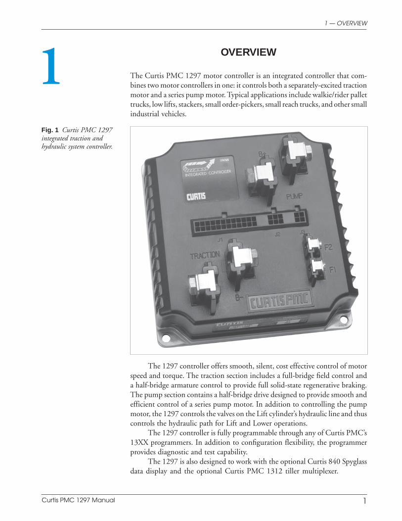
The Curtis PMC 1297 motor controller is an integrated controller that com-bines two motor controllers in one: it controls both a separately-excited tractionmotor and a series pump motor. Typical applications include walkie/rider pallettrucks, low lifts, stackers, small order-pickers, small reach trucks, and other smallindustrial vehicles.
1Fig. 1 Curtis PMC 1297integrated traction andhydraulic system controller.
The 1297 controller offers smooth, silent, cost effective control of motorspeed and torque. The traction section includes a full-bridge field control anda half-bridge armature control to provide full solid-state regenerative braking.The pump section contains a half-bridge drive designed to provide smooth andefficient control of a series pump motor. In addition to controlling the pumpmotor, the 1297 controls the valves on the Lift cylinder’s hydraulic line and thuscontrols the hydraulic path for Lift and Lower operations.
The 1297 controller is fully programmable through any of Curtis PMC’s13XX programmers. In addition to configuration flexibility, the programmerprovides diagnostic and test capability.
The 1297 is also designed to work with the optional Curtis 840 Spyglassdata display and the optional Curtis PMC 1312 tiller multiplexer.
Curtis PMC 1297 Manual 2
Preliminary on Verso page is set with right edge at 7 and 7/8,
and the top (as on the Recto page) at 1/4.
1 — OVERVIEW
Like all Curtis PMC motor controllers, the 1297 offers superior operatorcontrol of motor speed. Features include:
150–350 amp separately excited regenerative traction motor controller
Field current standard at 25 amps on 150 and 250 amp controllers,and at 35 amps on 350 amp controllers
MultiMode™ feature allows two distinct user-selectable operation modes
200–300 amp series pump motor controller, with choice of variablePWM or ramped on/off
Proportional lowering valve is controlled by a variable-current driver,for precise control during lowering
Lift and Lower operations start smoothly, because of hydraulic systempre-load function
Programmability through the Curtis PMC 13XX programmer
Complete diagnostics through the 13XX programmer and throughthe controller’s built-in Status LED
Throttle inputs for single-ended or wigwag 5kΩ pots or 0–5V throttles(both standard full stroke and restricted range); one throttle for thetraction system and one for the hydraulic system
Active precharge of controller capacitor bank extends life of maincontactor tips
Three hourmeters—total KSI-on hours, drive hours, pump hours—andtheir associated maintenance timers are built into the controller, withEEPROM storage (no battery)
BDI calculations performed within controller
Meets EEC fault detection requirements (standard M- PWM fault check)
Fault detection circuitry on throttle inputs can be used to inhibitoperation if traction or hydraulic throttle signal goes out of rangefor any reason
Internal reverse polarity protection (no external diode required)
Continuous diagnostics during operation, with microprocessorpower-on self-test
All output drivers are short-circuit protected and provide built-incoil spike protection
Positive battery connections for all inputs
Curtis PMC 1297 Manual 3
Preliminary on Verso page is set with right edge at 7 and 7/8,
and the top (as on the Recto page) at 1/4.
Fully protected inputs
Internal and external watchdog circuits ensure proper software operation
High environmental protection rating (IP53)
3-wire serial interface for multifunction display—see below
4-wire serial interface for all tiller functions—see below
Curtis Model 840 Spyglass Display
3-wire serial interface
Sequences between hourmeter, BDI, and error displays
Single alphanumeric, non-backlit, 8 character, 5 mm LCD display forhourmeter, BDI, and fault messages
Display updated by dedicated unidirectional serial port
Available in 52 mm round case, DIN case, and as a bare board, eachwith an 8-pin Molex connector; cases feature front seal to IP65 and rearseal to IP40; shock and vibration protection to SAE J1378
Operating temperature range -10°C to 70°C; models with lowertemperature ratings available for freezer applications
Curtis PMC Model 1312 Tiller Multiplexer
4-wire serial interface increases reliability
Multiplexes up to 12 signals, analog or digital
All signals sampled 50 times per second
Signal integrity checked 150 times per second
Schematic drawing of the 1312 generic circuit board is available at nocost to OEMs who want to design their own tiller multiplexers.
Familiarity with your Curtis PMC controller will help you install and operateit properly. We encourage you to read this manual carefully. If you havequestions, please contact the Curtis office nearest you.
1 — OVERVIEW
Curtis PMC 1297 Manual 4
Preliminary on Verso page is set with right edge at 7 and 7/8,
and the top (as on the Recto page) at 1/4.
INSTALLATION AND WIRING
MOUNTING THE CONTROLLER
The 1297 controller can be oriented in any position, and meets the IP53 ratingsfor environmental protection against dust and water. However, the locationshould be carefully chosen to keep the controller clean and dry. If a clean,dry mounting location cannot be found, a cover must be used to shield thecontroller from water and contaminants.
When selecting the mounting position, be sure to also take into consid-eration (1) that the built-in Status LED is visible only through the view port inthe label on top of the controller, and (2) that convenient access is needed at thetop of the controller to plug the programmer into its connector.
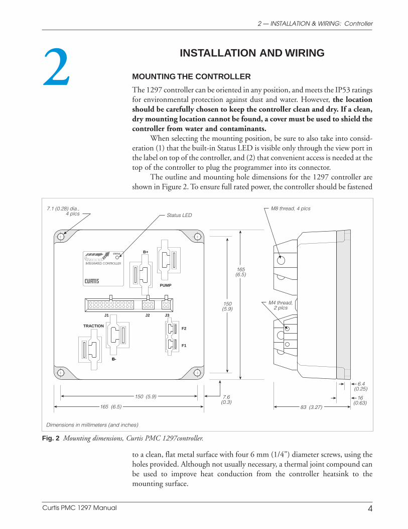
The outline and mounting hole dimensions for the 1297 controller areshown in Figure 2. To ensure full rated power, the controller should be fastened
22 — INSTALLATION & WIRING: Controller
Fig. 2 Mounting dimensions, Curtis PMC 1297controller.
Dimensions in millimeters (and inches)
to a clean, flat metal surface with four 6 mm (1/4") diameter screws, using theholes provided. Although not usually necessary, a thermal joint compound canbe used to improve heat conduction from the controller heatsink to themounting surface.
STATUS
INTEGRATED CONTROLLER
B-
TRACTION
PUMP
B+
Status LED7.1 (0.28) dia.,
4 plcs
150 (5.9)
165 (6.5) 83 (3.27)
M8 thread, 4 plcs
M4 thread,2 plcs
7.6(0.3)
150(5.9)
165(6.5)
6.4(0.25)
16(0.63)
B-
J1 J2 J3
F2
F1
Curtis PMC 1297 Manual 5
Preliminary on Verso page is set with right edge at 7 and 7/8,
and the top (as on the Recto page) at 1/4.
2 — INSTALLATION & WIRING: Controller
Working on electrical systems is potentially dangerous. You shouldprotect yourself against uncontrolled operation, high current arcs, andoutgassing from lead acid batteries:
UNCONTROLLED TRACTION OPERATION — Some conditions could cause thetraction system to run out of control. Disconnect the motor or jack up thevehicle and get the drive wheels off the ground before attempting any workon the traction motor control circuitry. NOTE: If the wrong throttle inputsignal type is selected with the 13XX programmer, the vehicle maysuddenly begin to move.
UNCONTROLLED HYDRAULIC OPERATION — Some conditions could cause thehydraulic system to run out of control. Disconnect the pump motor ormake sure the hydraulic system has enough room to operate beforeattempting any work on the pump motor control circuitry. NOTE: If thewrong hydraulic throttle input signal type is selected with the 13XXprogrammer, the hydraulic system may suddenly begin to operate.
HIGH CURRENT ARCS — Batteries can supply very high power, and arcs canoccur if they are short circuited. Always open the battery circuit beforeworking on the motor control circuit. Wear safety glasses, and use properlyinsulated tools to prevent shorts.
LEAD ACID BATTERIES — Charging or discharging generates hydrogen gas,which can build up in and around the batteries. Follow the batterymanufacturer’s safety recommendations. Wear safety glasses.
You will need to take steps during the design and development of yourend product to ensure that its EMC performance complies with applicableregulations; suggestions are presented in Appendix C.
The 1297 controller contains ESD-sensitive components. Use appro-priate precautions in connecting, disconnecting, and handling the controller.See installation suggestions in Appendix C for protecting the controller fromESD damage.
C A U T I O N
Curtis PMC 1297 Manual 6
Preliminary on Verso page is set with right edge at 7 and 7/8,
and the top (as on the Recto page) at 1/4.
CONNECTIONS
Low Current Connections
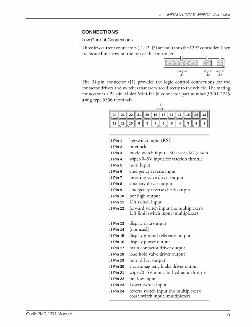
Three low current connectors (J1, J2, J3) are built into the 1297 controller. Theyare located in a row on the top of the controller:
2 — INSTALLATION & WIRING: Controller
J1 Pin 1 keyswitch input (KSI)J1 Pin 2 interlockJ1 Pin 3 mode switch input—M1 (open), M2 (closed)
J1 Pin 4 wiper/0–5V input for traction throttleJ1 Pin 5 horn inputJ1 Pin 6 emergency reverse inputJ1 Pin 7 lowering valve driver outputJ1 Pin 8 auxiliary driver outputJ1 Pin 9 emergency reverse check outputJ1 Pin 10 pot high outputJ1 Pin 11 Lift switch inputJ1 Pin 12 forward switch input (no multiplexer);
Lift limit switch input (multiplexer)
J1 Pin 13 display data outputJ1 Pin 14 [not used]J1 Pin 15 display ground reference outputJ1 Pin 16 display power outputJ1 Pin 17 main contactor driver outputJ1 Pin 18 load hold valve driver outputJ1 Pin 19 horn driver outputJ1 Pin 20 electromagnetic brake driver outputJ1 Pin 21 wiper/0–5V input for hydraulic throttleJ1 Pin 22 pot low inputJ1 Pin 23 Lower switch inputJ1 Pin 24 reverse switch input (no multiplexer);
coast switch input (multiplexer)
24 23 22 21 20 19 18 17 16 15 14 13
12 11 10 9 8 7 6 5 4 3 2 1
The 24-pin connector (J1) provides the logic control connections for thecontactor drivers and switches that are wired directly to the vehicle. The matingconnector is a 24-pin Molex Mini-Fit Jr. connector part number 39-01-2245using type 5556 terminals.
24-pin 6-pin 4-pinJ1 J2 J3
J1
Curtis PMC 1297 Manual 7
Preliminary on Verso page is set with right edge at 7 and 7/8,
and the top (as on the Recto page) at 1/4.
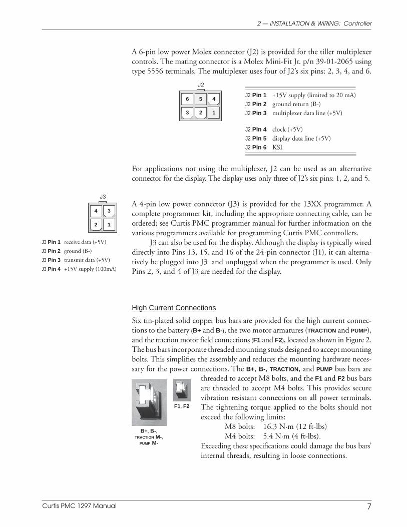
A 6-pin low power Molex connector (J2) is provided for the tiller multiplexercontrols. The mating connector is a Molex Mini-Fit Jr. p/n 39-01-2065 usingtype 5556 terminals. The multiplexer uses four of J2’s six pins: 2, 3, 4, and 6.
456
123
J2 Pin 1 +15V supply (limited to 20 mA)J2 Pin 2 ground return (B-)J2 Pin 3 multiplexer data line (+5V)
J2 Pin 4 clock (+5V)J2 Pin 5 display data line (+5V)J2 Pin 6 KSI
34
12
threaded to accept M8 bolts, and the F1 and F2 bus barsare threaded to accept M4 bolts. This provides securevibration resistant connections on all power terminals.The tightening torque applied to the bolts should notexceed the following limits:
M8 bolts: 16.3 N·m (12 ft-lbs)M4 bolts: 5.4 N·m (4 ft-lbs).
Exceeding these specifications could damage the bus bars’internal threads, resulting in loose connections.
For applications not using the multiplexer, J2 can be used as an alternativeconnector for the display. The display uses only three of J2’s six pins: 1, 2, and 5.
A 4-pin low power connector (J3) is provided for the 13XX programmer. Acomplete programmer kit, including the appropriate connecting cable, can beordered; see Curtis PMC programmer manual for further information on thevarious programmers available for programming Curtis PMC controllers.
J3 can also be used for the display. Although the display is typically wireddirectly into Pins 13, 15, and 16 of the 24-pin connector (J1), it can alterna-tively be plugged into J3 and unplugged when the programmer is used. OnlyPins 2, 3, and 4 of J3 are needed for the display.
High Current Connections
Six tin-plated solid copper bus bars are provided for the high current connec-tions to the battery (B+ and B-), the two motor armatures (TRACTION and PUMP),and the traction motor field connections (F1 and F2), located as shown in Figure 2.The bus bars incorporate threaded mounting studs designed to accept mountingbolts. This simplifies the assembly and reduces the mounting hardware neces-sary for the power connections. The B+, B-, TRACTION, and PUMP bus bars are
J2
J3
J3 Pin 1 receive data (+5V)
J3 Pin 2 ground (B-)
J3 Pin 3 transmit data (+5V)
J3 Pin 4 +15V supply (100mA)
F1, F2
B+, B-,TRACTION M-,
PUMP M-
2 — INSTALLATION & WIRING: Controller
Curtis PMC 1297 Manual 8
Preliminary on Verso page is set with right edge at 7 and 7/8,
and the top (as on the Recto page) at 1/4.
2 — INSTALLATION & WIRING: Controller
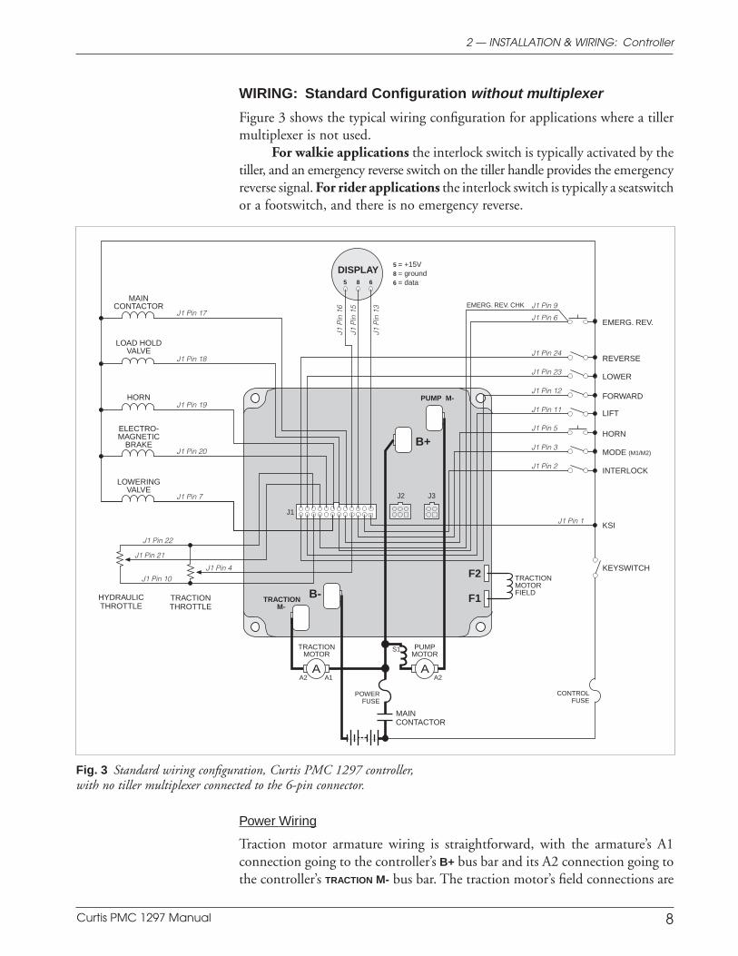
WIRING: Standard Configuration without multiplexer
Figure 3 shows the typical wiring configuration for applications where a tillermultiplexer is not used.
For walkie applications the interlock switch is typically activated by thetiller, and an emergency reverse switch on the tiller handle provides the emergencyreverse signal. For rider applications the interlock switch is typically a seatswitchor a footswitch, and there is no emergency reverse.
Power Wiring
Traction motor armature wiring is straightforward, with the armature’s A1connection going to the controller’s B+ bus bar and its A2 connection going tothe controller’s TRACTION M- bus bar. The traction motor’s field connections are
Fig. 3 Standard wiring configuration, Curtis PMC 1297 controller,with no tiller multiplexer connected to the 6-pin connector.
5 = +15V8 = ground6 = data
HORN
MODE (M1/M2)
LIFT
MAINCONTACTOR
HYDRAULICTHROTTLE
TRACTIONM-
B-
B+
LOWER
INTERLOCK
KSI
DISPLAY
LOWERINGVALVE
J1 Pin 7
ELECTRO-MAGNETIC
BRAKEJ1 Pin 20
HORNJ1 Pin 19
LOAD HOLDVALVE
J1 Pin 18
MAINCONTACTOR
J1 Pin 17
PUMP M-
F2
F1
J1
J2 J3
TRACTIONTHROTTLE
POWERFUSE
5 8 6
J1 Pin 22
J1 Pin 4
J1 Pin 24
J1 Pin 23
J1 Pin 12
J1 Pin 11
J1 Pin 5
J1 Pin 3
J1 Pin 2
J1 Pin 1
J1 Pin 10
J1 P
in 1
6
J1 P
in 1
3
J1 P
in 1
5
A
J1 Pin 21
A
KEYSWITCH
TRACTIONMOTOR
PUMPMOTOR
CONTROLFUSE
A2 A1 A2
TRACTIONMOTORFIELD
S1
REVERSE
FORWARD
EMERG. REV. CHK J1 Pin 9
J1 Pin 6EMERG. REV.
Curtis PMC 1297 Manual 9
Preliminary on Verso page is set with right edge at 7 and 7/8,
and the top (as on the Recto page) at 1/4.
2 — INSTALLATION & WIRING: Controller
less obvious. The direction of vehicle travel with the forward direction selectedwill depend on how the motor’s field connections are made to the controller’stwo field terminals and how the motor shaft is connected to the drive wheelsthrough the vehicle’s drive train. CAUTION: The polarity of the F1 and F2
connections will affect the operation of the emergency reverse feature. Theforward and reverse switches and the field connections must be configured sothat the vehicle drives away from the operator when the emergency reversebutton is pressed.
The pump motor is wired as shown, with its S1 connection going to theB+ bus bar and its A2 connection going to the PUMP M- bus bar.
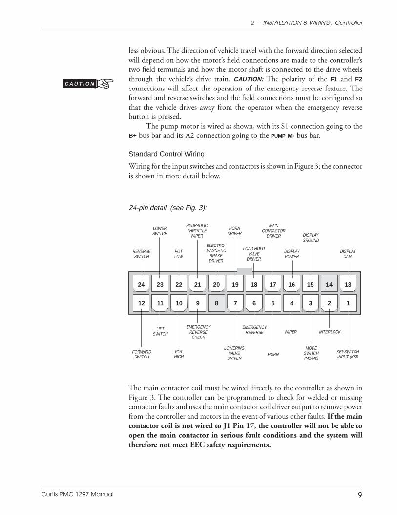
Standard Control Wiring
Wiring for the input switches and contactors is shown in Figure 3; the connectoris shown in more detail below.
The main contactor coil must be wired directly to the controller as shown inFigure 3. The controller can be programmed to check for welded or missingcontactor faults and uses the main contactor coil driver output to remove powerfrom the controller and motors in the event of various other faults. If the maincontactor coil is not wired to J1 Pin 17, the controller will not be able toopen the main contactor in serious fault conditions and the system willtherefore not meet EEC safety requirements.
12 11 10 9 8 7 6 5 4 3 2 1
24 23 22 21 20 19 18 17 16 15 14 13
INTERLOCKEMERGENCY
REVERSE
HORNFORWARDSWITCH
24-pin detail (see Fig. 3):
LOWERINGVALVE
DRIVER
LOAD HOLDVALVE
DRIVER
MAINCONTACTOR
DRIVER DISPLAYGROUND
HYDRAULICTHROTTLE
WIPER
KEYSWITCHINPUT (KSI)
POTHIGH
EMERGENCYREVERSE
CHECK
ELECTRO-MAGNETIC
BRAKEDRIVER
DISPLAYPOWER
WIPERLIFT
SWITCH
DISPLAYDATA
LOWERSWITCH
POTLOW
REVERSESWITCH
HORNDRIVER
MODESWITCH(M1/M2)
C A U T I O N
Curtis PMC 1297 Manual 10
Preliminary on Verso page is set with right edge at 7 and 7/8,
and the top (as on the Recto page) at 1/4.
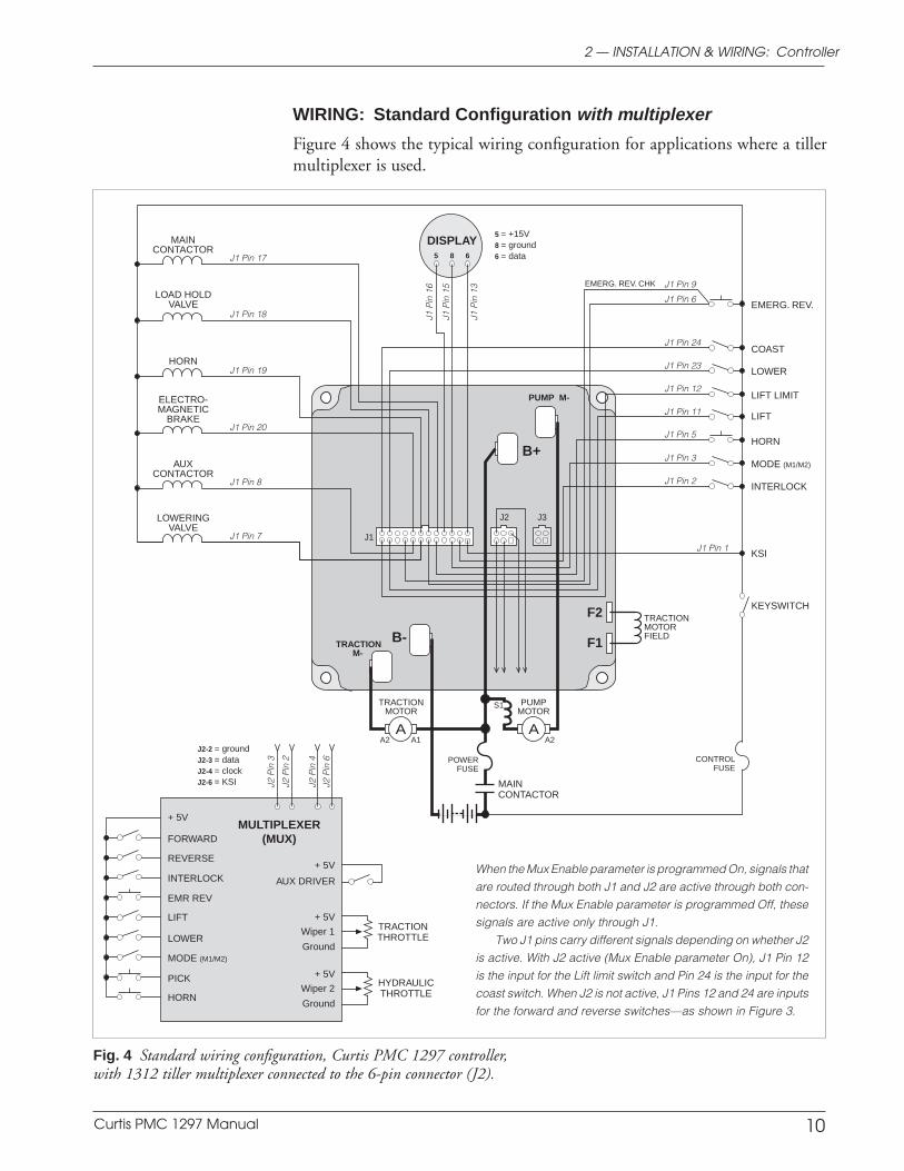
WIRING: Standard Configuration with multiplexer
Figure 4 shows the typical wiring configuration for applications where a tillermultiplexer is used.
2 — INSTALLATION & WIRING: Controller
Fig. 4 Standard wiring configuration, Curtis PMC 1297 controller,with 1312 tiller multiplexer connected to the 6-pin connector (J2).
5 = +15V8 = ground6 = data
HORN
MODE (M1/M2)
LIFT
MAINCONTACTOR
TRACTIONM-
B-
B+
LOWER
INTERLOCK
KSI
DISPLAY
LOWERINGVALVE
J1 Pin 7
ELECTRO-MAGNETIC
BRAKEJ1 Pin 20
HORNJ1 Pin 19
LOAD HOLDVALVE
J1 Pin 18
MAINCONTACTOR
J1 Pin 17
PUMP M-
F2
F1
J1
J2 J3
POWERFUSE
AUXCONTACTOR
J1 Pin 8
5 8 6
J1 Pin 24
J1 Pin 23
J1 Pin 12
J1 Pin 11
J1 Pin 5
J1 Pin 3
J1 Pin 2
J1 Pin 1
J1 P
in 1
6
J1 P
in 1
3
J1 P
in 1
5
A A
EMERG. REV. CHK J1 Pin 9
J1 Pin 6EMERG. REV.
KEYSWITCH
TRACTIONMOTOR
PUMPMOTOR
CONTROLFUSE
A2 A1 A2
TRACTIONMOTORFIELD
S1
FORWARD
INTERLOCK
LOWER
MODE (M1/M2)
LIFT
REVERSE
HORN
+ 5VMULTIPLEXER
(MUX)
J2 P
in 3
J2 P
in 2
J2 P
in 4
J2 P
in 6
+ 5V
Wiper 1
Ground
+ 5V
Wiper 2
Ground
J2-2 = groundJ2-3 = dataJ2-4 = clockJ2-6 = KSI
LIFT LIMIT
COAST
PICK
EMR REV
HYDRAULICTHROTTLE
TRACTIONTHROTTLE
+ 5V
AUX DRIVERWhen the Mux Enable parameter is programmed On, signals thatare routed through both J1 and J2 are active through both con-nectors. If the Mux Enable parameter is programmed Off, thesesignals are active only through J1.
Two J1 pins carry different signals depending on whether J2is active. With J2 active (Mux Enable parameter On), J1 Pin 12is the input for the Lift limit switch and Pin 24 is the input for thecoast switch. When J2 is not active, J1 Pins 12 and 24 are inputsfor the forward and reverse switches—as shown in Figure 3.
Curtis PMC 1297 Manual 11
Preliminary on Verso page is set with right edge at 7 and 7/8,
and the top (as on the Recto page) at 1/4.
Power Wiring
Traction motor armature wiring is straightforward, with the armature’s A1connection going to the controller’s B+ bus bar and its A2 connection going tothe controller’s TRACTION M- bus bar. The traction motor’s field connections areless obvious. The direction of vehicle travel with the forward direction selectedwill depend on how the motor’s field connections are made to the controller’stwo field terminals and how the motor shaft is connected to the drive wheelsthrough the vehicle’s drive train. CAUTION: The polarity of the F1 and F2
connections will affect the operation of the emergency reverse feature. Theforward and reverse switches and the field connections must be configured sothat the vehicle drives away from the operator when the emergency reversebutton is pressed.
The pump motor is wired as shown, with its S1 connection going to theB+ bus bar and its A2 connection going to the PUMP M- bus bar.
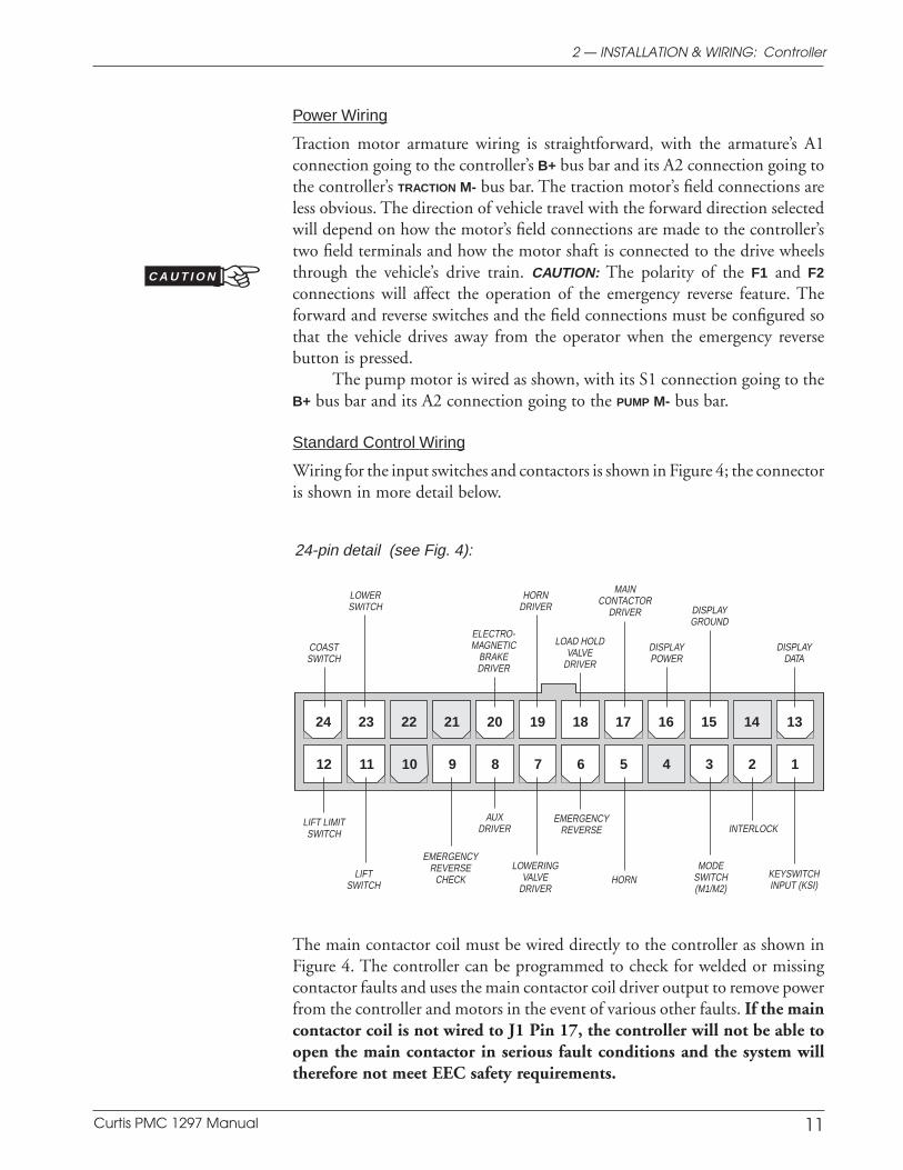
Standard Control Wiring
Wiring for the input switches and contactors is shown in Figure 4; the connectoris shown in more detail below.
The main contactor coil must be wired directly to the controller as shown inFigure 4. The controller can be programmed to check for welded or missingcontactor faults and uses the main contactor coil driver output to remove powerfrom the controller and motors in the event of various other faults. If the maincontactor coil is not wired to J1 Pin 17, the controller will not be able toopen the main contactor in serious fault conditions and the system willtherefore not meet EEC safety requirements.
2 — INSTALLATION & WIRING: Controller
INTERLOCKEMERGENCY
REVERSE
HORN
LIFT LIMITSWITCH
24-pin detail (see Fig. 4):
LOWERINGVALVE
DRIVER
LOAD HOLDVALVE
DRIVER
MAINCONTACTOR
DRIVER DISPLAYGROUND
AUXDRIVER
KEYSWITCHINPUT (KSI)
EMERGENCYREVERSE
CHECK
ELECTRO-MAGNETIC
BRAKEDRIVER
DISPLAYPOWER
LIFTSWITCH
DISPLAYDATA
LOWERSWITCH
COASTSWITCH
HORNDRIVER
MODESWITCH(M1/M2)
24 23 22 21 20 19 18 17 16 15 14 13
12 11 10 9 8 7 6 5 4 3 2 1
C A U T I O N
Curtis PMC 1297 Manual 12
Preliminary on Verso page is set with right edge at 7 and 7/8,
and the top (as on the Recto page) at 1/4.
2 — INSTALLATION & WIRING: Throttles
WIRING: Throttles
Various throttles can be used with the 1297 controller. They are categorized asone of four types in the programming menu of the 13XX programmer. OnlyTypes 2 and 4 can be used for the hydraulic throttle.
Type 1: two-wire 5kΩ–0 potentiometer throttlesType 2: 0–5V throttles, current source throttles, three-wire pot throttles,
and electronic throttles—wired for single-ended operationType 3: two-wire 0–5kΩ potentiometer throttlesType 4: 0–5V and three-wire pot throttles—wired for wigwag-style
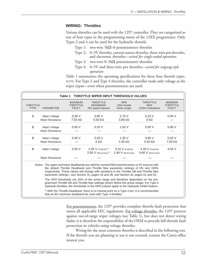
operationTable 1 summarizes the operating specifications for these four throttle types.NOTE: For Type 2 and Type 4 throttles, the controller reads only voltage at thewiper input—even when potentiometers are used.
Table 1 THROTTLE WIPER INPUT THRESHOLD VALUES
MAXIMUM THROTTLE HPD THROTTLE MINIMUMTHROTTLE THROTTLE DEADBAND (25% throttle MAX THROTTLE
TYPE PARAMETER FAULT (0% speed request) active range) (100% modulation) FAULT
1 Wiper Voltage 5.00 V 3.80 V 2.70 V 0.20 V 0.06 VWiper Resistance 7.50 kΩ 5.50 kΩ 3.85 kΩ 0 kΩ —
2 Wiper Voltage 0.06 V 0.20 V 1.50 V 5.00 V 5.80 VWiper Resistance — — — — —
3 Wiper Voltage 0.06 V 0.20 V 1.30 V 3.80 V 5.00 VWiper Resistance — 0 kΩ 1.65 kΩ 5.50 kΩ 7.50 kΩ
4 Wiper Voltage 0.50 V 2.50 V (Fwd/Lift) * 3.10 V (Fwd/Lift) 4.40 V (Fwd/Lift) 4.50 V2.50 V (Rev/Lower) * 1.90 V (Rev/Lower) 0.60 V (Rev/Lower)
Wiper Resistance — — — — —
Notes: The upper and lower deadbands are valid for nominal 5kΩ potentiometers or 5V sources withthe default Throttle Deadband and Throttle Max parameter settings of 0% and 100%respectively. These values will change with variations in the Throttle DB and Throttle Maxparameter settings—see Section 3A, pages 34 and 36, and Section 3B, pages 51 and 53.
The HPD thresholds are 25% of the active range and therefore dependent on the pro-grammed Throttle DB and Throttle Max settings (which define the active range). For Type 4hydraulic throttles, the thresholds in the HPD column apply to the Hydraulic Inhibit feature.
* With 0% Throttle Deadband, there is no neutral point on a Type 4 pot. It is recommendedthat an 8% minimum deadband be used with Type 4 throttles.
For potentiometers, the 1297 provides complete throttle fault protection thatmeets all applicable EEC regulations. For voltage throttles, the 1297 protectsagainst out-of-range wiper voltages (see Table 1), but does not detect wiringfaults; it is therefore the responsibility of the OEM to provide full throttle faultprotection in vehicles using voltage throttles.
Wiring for the most common throttles is described in the following text.If the throttle you are planning to use is not covered, contact the Curtis officenearest you.
Curtis PMC 1297 Manual 13
Preliminary on Verso page is set with right edge at 7 and 7/8,
and the top (as on the Recto page) at 1/4.
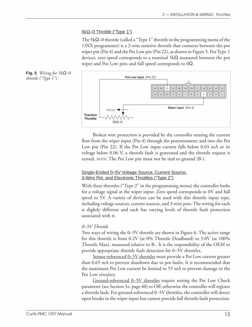
5kΩ–0 Throttle (“Type 1”)
The 5kΩ–0 throttle (called a “Type 1” throttle in the programming menu of the13XX programmer) is a 2-wire resistive throttle that connects between the potwiper pin (Pin 4) and the Pot Low pin (Pin 22), as shown in Figure 5. For Type 1devices, zero speed corresponds to a nominal 5kΩ measured between the potwiper and Pot Low pins and full speed corresponds to 0Ω.
Fig. 5 Wiring for 5kΩ–0throttle (“Type 1”).
14 1315161718192021222324
12 11 10 9 8 7 6 5 4 3 2 1
5kΩ–0
Pot Low input (Pin 22)
TractionThrottle
Wiper input (Pin 4)FASTER
J1
2 — INSTALLATION & WIRING: Throttles
Broken wire protection is provided by the controller sensing the currentflow from the wiper input (Pin 4) through the potentiometer and into the PotLow pin (Pin 22). If the Pot Low input current falls below 0.65 mA or itsvoltage below 0.06 V, a throttle fault is generated and the throttle request iszeroed. NOTE: The Pot Low pin must not be tied to ground (B-).
Single-Ended 0–5V Voltage Source, Current Source,3-Wire Pot, and Electronic Throttles (“Type 2”)
With these throttles (“Type 2” in the programming menu) the controller looksfor a voltage signal at the wiper input. Zero speed corresponds to 0V and fullspeed to 5V. A variety of devices can be used with this throttle input type,including voltage sources, current sources, and 3-wire pots. The wiring for eachis slightly different and each has varying levels of throttle fault protectionassociated with it.
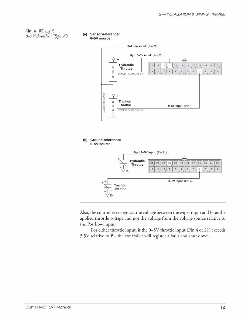
0–5V ThrottleTwo ways of wiring the 0–5V throttle are shown in Figure 6. The active rangefor this throttle is from 0.2V (at 0% Throttle Deadband) to 5.0V (at 100%Throttle Max), measured relative to B-. It is the responsibility of the OEM toprovide appropriate throttle fault detection for 0–5V throttles.
Sensor-referenced 0–5V throttles must provide a Pot Low current greaterthan 0.65 mA to prevent shutdown due to pot faults. It is recommended thatthe maximum Pot Low current be limited to 55 mA to prevent damage to thePot Low circuitry.
Ground-referenced 0–5V throttles require setting the Pot Low Checkparameter (see Section 3A, page 40) to Off; otherwise the controller will registera throttle fault. For ground-referenced 0–5V throttles, the controller will detectopen breaks in the wiper input but cannot provide full throttle fault protection.
Curtis PMC 1297 Manual 14
Preliminary on Verso page is set with right edge at 7 and 7/8,
and the top (as on the Recto page) at 1/4.
14 1315161718192021222324
12 11 10 9 8 7 6 5 4 3 2 1
14 1315161718192021222324
12 11 10 9 8 7 6 5 4 3 2 1
+
-B-
++
-B-
+
SENSOR OUTPUT (0–5V)
J1
SE
NS
OR
SE
NS
OR
GR
OU
ND
J1
SENSOR OUTPUT (0–5V)S
EN
SO
R
Pot Low input (Pin 22)
Hyd. 0–5V input (Pin 21)
0–5V input (Pin 4)
Hyd. 0–5V input (Pin 21)
0–5V input (Pin 4)
TractionThrottle
HydraulicThrottle
TractionThrottle
HydraulicThrottle
Also, the controller recognizes the voltage between the wiper input and B- as theapplied throttle voltage and not the voltage from the voltage source relative tothe Pot Low input.
For either throttle input, if the 0–5V throttle input (Pin 4 or 21) exceeds5.5V relative to B-, the controller will register a fault and shut down.
Fig. 6 Wiring for0–5V throttles (“Type 2”).
(b) Ground-referenced0–5V source
(a) Sensor-referenced0–5V source
2 — INSTALLATION & WIRING: Throttles
Curtis PMC 1297 Manual 15
Preliminary on Verso page is set with right edge at 7 and 7/8,
and the top (as on the Recto page) at 1/4.
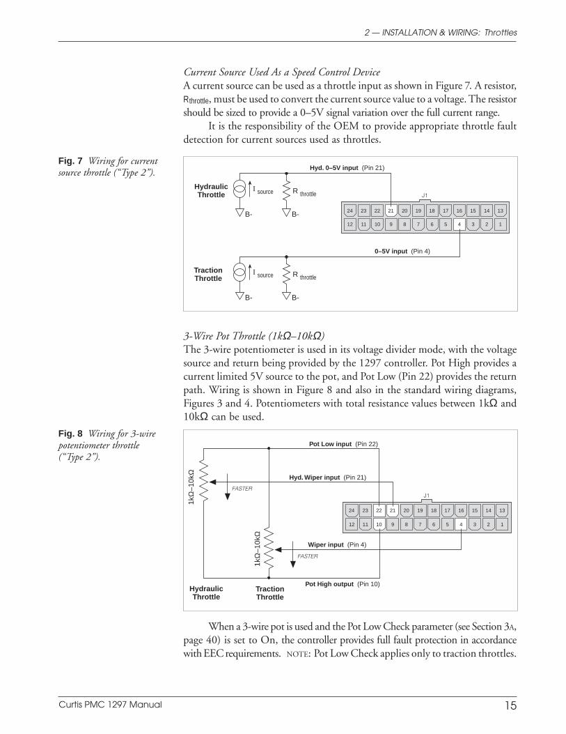
Current Source Used As a Speed Control DeviceA current source can be used as a throttle input as shown in Figure 7. A resistor,Rthrottle, must be used to convert the current source value to a voltage. The resistorshould be sized to provide a 0–5V signal variation over the full current range.
It is the responsibility of the OEM to provide appropriate throttle faultdetection for current sources used as throttles.
Fig. 8 Wiring for 3-wirepotentiometer throttle(“Type 2”).
3-Wire Pot Throttle (1kΩ–10kΩ)The 3-wire potentiometer is used in its voltage divider mode, with the voltagesource and return being provided by the 1297 controller. Pot High provides acurrent limited 5V source to the pot, and Pot Low (Pin 22) provides the returnpath. Wiring is shown in Figure 8 and also in the standard wiring diagrams,Figures 3 and 4. Potentiometers with total resistance values between 1kΩ and10kΩ can be used.
Fig. 7 Wiring for currentsource throttle (“Type 2”).
14 1315161718192021222324
12 11 10 9 8 7 6 5 4 3 2 1
1kΩ
–10k
Ω
J1
1kΩ
–10k
Ω
Wiper input (Pin 4)
Pot Low input (Pin 22)
Pot High output (Pin 10)TractionThrottle
HydraulicThrottle
Hyd. Wiper input (Pin 21)
FASTER
FASTER
14 1315161718192021222324
12 11 10 9 8 7 6 5 4 3 2 1
R throttleI source
B-B-
R throttleI source
B-B-
J1
0–5V input (Pin 4)
TractionThrottle
HydraulicThrottle
Hyd. 0–5V input (Pin 21)
2 — INSTALLATION & WIRING: Throttles
When a 3-wire pot is used and the Pot Low Check parameter (see Section 3A,page 40) is set to On, the controller provides full fault protection in accordancewith EEC requirements. NOTE: Pot Low Check applies only to traction throttles.
Curtis PMC 1297 Manual 16
Preliminary on Verso page is set with right edge at 7 and 7/8,
and the top (as on the Recto page) at 1/4.
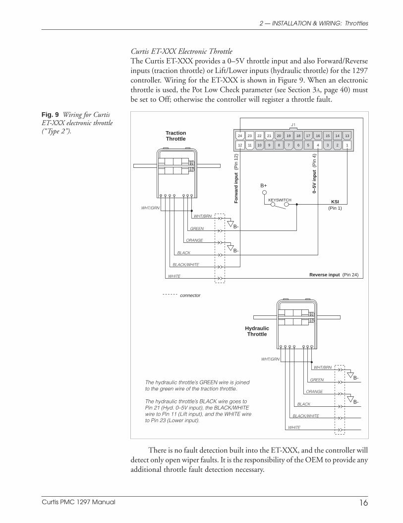
Fig. 9 Wiring for CurtisET-XXX electronic throttle(“Type 2”).
Curtis ET-XXX Electronic ThrottleThe Curtis ET-XXX provides a 0–5V throttle input and also Forward/Reverseinputs (traction throttle) or Lift/Lower inputs (hydraulic throttle) for the 1297controller. Wiring for the ET-XXX is shown in Figure 9. When an electronicthrottle is used, the Pot Low Check parameter (see Section 3A, page 40) mustbe set to Off; otherwise the controller will register a throttle fault.
There is no fault detection built into the ET-XXX, and the controller willdetect only open wiper faults. It is the responsibility of the OEM to provide anyadditional throttle fault detection necessary.
2 — INSTALLATION & WIRING: Throttles
14 1315161718192021222324
12 11 10 9 8 7 6 5 4 3 2 1
GREEN
ORANGE
BLACK
BLACK/WHITE
WHITE
WHT/BRN
B+
KEYSWITCH
connector
WHT/GRN
J1
GREEN
ORANGE
BLACK
BLACK/WHITE
WHITE
WHT/BRN
WHT/GRN
The hydraulic throttle’s GREEN wire is joinedto the green wire of the traction throttle.
The hydraulic throttle’s BLACK wire goes toPin 21 (Hyd. 0–5V input), the BLACK/WHITEwire to Pin 11 (Lift input), and the WHITE wireto Pin 23 (Lower input).
B-
B-
B-
B-
Reverse input (Pin 24)
KSI(Pin 1)
0–5V
inp
ut
(P
in 4
)
Fo
rwar
d in
pu
t (
Pin
12)
TractionThrottle
HydraulicThrottle
Curtis PMC 1297 Manual 17
Preliminary on Verso page is set with right edge at 7 and 7/8,
and the top (as on the Recto page) at 1/4.
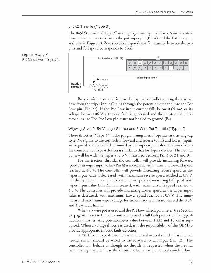
Fig. 10 Wiring for0–5kΩ throttle (“Type 3”).
0–5kΩ Throttle (“Type 3”)
The 0–5kΩ throttle (“Type 3” in the programming menu) is a 2-wire resistivethrottle that connects between the pot wiper pin (Pin 4) and the Pot Low pin,as shown in Figure 10. Zero speed corresponds to 0Ω measured between the twopins and full speed corresponds to 5 kΩ.
14 1315161718192021222324
12 11 10 9 8 7 6 5 4 3 2 1
0–5kΩ
Pot Low input (Pin 22)
TractionThrottle
Wiper input (Pin 4)FASTER
J1
2 — INSTALLATION & WIRING: Throttles
Broken wire protection is provided by the controller sensing the currentflow from the wiper input (Pin 4) through the potentiometer and into the PotLow pin (Pin 22). If the Pot Low input current falls below 0.65 mA or itsvoltage below 0.06 V, a throttle fault is generated and the throttle request iszeroed. NOTE: The Pot Low pin must not be tied to ground (B-).
Wigwag-Style 0–5V Voltage Source and 3-Wire Pot Throttle (“Type 4”)
These throttles (“Type 4” in the programming menu) operate in true wigwagstyle. No signals to the controller’s forward and reverse (or lift and lower) inputsare required; the action is determined by the wiper input value. The interface tothe controller for Type 4 devices is similar to that for Type 2 devices. The neutralpoint will be with the wiper at 2.5 V, measured between Pin 4 or 21 and B-.
For the traction throttle, the controller will provide increasing forwardspeed as its wiper input value (Pin 4) is increased, with maximum forward speedreached at 4.5 V. The controller will provide increasing reverse speed as thewiper input value is decreased, with maximum reverse speed reached at 0.5 V.For the hydraulic throttle, the controller will provide increasing Lift speed as itswiper input value (Pin 21) is increased, with maximum Lift speed reached at4.5 V. The controller will provide increasing Lower speed as the wiper inputvalue is decreased, with maximum Lower speed reached at 0.5 V. The mini-mum and maximum wiper voltage for either throttle must not exceed the 0.5Vand 4.5V fault limits.
When a 3-wire pot is used and the Pot Low Check parameter (see Section3A, page 40) is set to On, the controller provides full fault protection for Type 4traction throttles. Any potentiometer value between 1 kΩ and 10 kΩ is sup-ported. When a voltage throttle is used, it is the responsibility of the OEM toprovide appropriate throttle fault detection.
NOTE: If your Type 4 throttle has an internal neutral switch, this internalneutral switch should be wired to the forward switch input (Pin 12). Thecontroller will behave as though no throttle is requested when the neutralswitch is high, and will use the throttle value when the neutral switch is low.

Curtis PMC 1297 Manual 18
Preliminary on Verso page is set with right edge at 7 and 7/8,
and the top (as on the Recto page) at 1/4.
WIRING: Auxiliary Driver (REQUIRES MULTIPLEXER)
The 1297 controller provides an auxiliary driver at Pin 8. This low side driver,designed to energize a contactor coil, can be used to perform a variety offunctions—such as engaging a brush motor. The output is rated at 2 amps, isovercurrent protected, and the turn-off is voltage clamped. The recommendedwiring for an auxiliary contactor coil is shown in Figure 4. The contactor coilor driver load should not be connected directly to B+. The on/off switch for theauxiliary driver is located on the multiplexer.
WIRING: Coast and Pick (REQUIRES MULTIPLEXER)
When a multiplexer is used, J1 Pin 24 is the Coast input—as shown in Figure 4,page 10. When the tiller is locked in the Coast position (activating the Coastswitch), the multiplexer’s Pick switch can be used to drive the vehicle a shortdistance forward. When the Pick switch is released, the vehicle coasts to a stop.
WIRING: Emergency Reverse
To implement the emergency reverse feature, J1 Pin 6 (the emergency reverseinput) must be connected to battery voltage. Emergency reverse is activatedwhen the keyswitch is on and the emergency reverse switch is pressed. After theemergency reverse switch is released, normal controller operation is not resumeduntil neutral (no direction) is selected or until the interlock switch is cycled. Therecommended wiring is shown in Figures 3 and 4, pages 8 and 10. The controllerprovides maximum braking torque as soon as the emergency reverse switch isclosed. The vehicle will then be automatically driven in the reverse direction atthe programmed emergency reverse current limit until the emergency reverseswitch is released.
CAUTION: The polarity of the F1 and F2 connections will affect theoperation of the emergency reverse feature. The forward and reverse switchesand the F1 and F2 connections must be configured so that the vehicle drives awayfrom the operator when the emergency reverse button is pressed.
WIRING: Emergency Reverse Check
Al wire connected directly to the emergency reverse switch provides for brokenwire detection when that feature is programmed On (see Section 3A, page 42).The emergency reverse check output wire periodically pulses the emergencyreverse circuit to check for continuity in the wiring. If there is no continuity, thecontroller output is inhibited until the wiring fault is corrected.
The emergency reverse check wire is connected to J1 Pin 9 as shown inFigures 3 and 4, pages 8 and 10. If the option is selected and the check wire is
2 — INSTALLATION & WIRING: Aux. Driver, Coast-and-Pick & Emerg. Reverse
C A U T I O N
Curtis PMC 1297 Manual 19
Preliminary on Verso page is set with right edge at 7 and 7/8,
and the top (as on the Recto page) at 1/4.
2 — INSTALLATION & WIRING: Emerg. Rev. Check & Spyglass
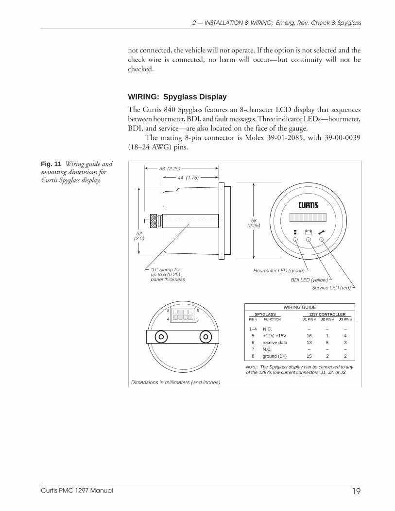
Fig. 11 Wiring guide andmounting dimensions forCurtis Spyglass display.
58(2.25)
44 (1.75)
8
58 (2.25)
Service LED (red)
BDI LED (yellow)
Hourmeter LED (green)
52(2.0)
“U” clamp forup to 6 (0.25)panel thickness
5
4 1
WIRING GUIDE
SPYGLASS 1297 CONTROLLERPIN # FUNCTION J1 PIN # J2 PIN # J3 PIN #
1–4 N.C. – – –
5 +12V, +15V 16 1 4
6 receive data 13 5 3
7 N.C. – – –
8 ground (B+) 15 2 2
NOTE: The Spyglass display can be connected to anyof the 1297’s low current connectors: J1, J2, or J3.
not connected, the vehicle will not operate. If the option is not selected and thecheck wire is connected, no harm will occur—but continuity will not bechecked.
WIRING: Spyglass Display
The Curtis 840 Spyglass features an 8-character LCD display that sequencesbetween hourmeter, BDI, and fault messages. Three indicator LEDs—hourmeter,BDI, and service—are also located on the face of the gauge.
The mating 8-pin connector is Molex 39-01-2085, with 39-00-0039(18–24 AWG) pins.
Dimensions in millimeters (and inches)
Curtis PMC 1297 Manual 20
Preliminary on Verso page is set with right edge at 7 and 7/8,
and the top (as on the Recto page) at 1/4.
CONTACTOR, SWITCHES, and OTHER HARDWARE
Main Contactor
A main contactor should be used with the 1297 controller. Otherwise, thecontroller’s fault detection will not be able to fully protect the controller, tractionsystem, and hydraulic system from damage in a fault condition. The contactorallows the controller and both motors to be disconnected from the battery. Thisprovides a significant safety feature, because it means the battery power can beremoved if a controller or wiring fault results in battery power being applied toeither motor inappropriately.
A single-pole, single-throw (SPST) contactor with silver-alloy contacts,such as an Albright SW180 or SW200 (available from Curtis), is recommendedfor use as the main contactor. The contactor coils should be specified with acontinuous rating at the nominal battery pack voltage.
The 1297 controller provides a low-side contactor coil driver (at J1 Pin 17)for the contactor. The driver output is rated at 2 amps, is overcurrent protectedat 3 amps, and is checked for open coil faults. An active clamping circuit at 70 Vprovides fast turn-off and protects the driver from inductive voltage kickbackspikes. The controller also performs a welded contactor check and a missingmain contactor check each time the interlock switch is engaged. Controlleroutput is inhibited if these contactor checks are not passed.
For information on programming the various contactor-related param-eters, see Section 3C, page 57.
Keyswitch and Interlock Switch
The vehicle should have a master on/off switch to turn the system off when notin use. The keyswitch input provides logic power for the controller.
The interlock switch—which is typically implemented as a tiller switch,deadman footswitch, or seatswitch—provides a safety interlock for the system.
The keyswitch and interlock switch provide current to drive the maincontactor coil and the valve solenoid coils as well as the controller’s internallogic circuitry, and must be rated to carry these currents.
Forward/Reverse, Lift/Lower, Mode, Emergency Reverse,Horn, Lift Limit, Coast, and Pick Switches
These input switches can be any type of single-pole, single-throw (SPST) switchcapable of switching the battery voltage at 25 mA. Typically the EmergencyReverse, Horn, and Pick switches are momentary switches, active only whilethey are being depressed.
Circuitry Protection Devices
To protect the control circuitry from accidental shorts, a low current fuse(appropriate for the maximum current draw) should be connected in series withthe battery feed to the keyswitch. Additionally, a high current fuse should be
2 — INSTALLATION & WIRING: Switches, etc.
Curtis PMC 1297 Manual 21
Preliminary on Verso page is set with right edge at 7 and 7/8,
and the top (as on the Recto page) at 1/4.
2 — INSTALLATION & WIRING: Switches, etc.
wired in series with the main contactor to protect the motors, controller, andbatteries from accidental shorts in the power system. The appropriate fuse foreach application should be selected with the help of a reputable fuse manufac-turer or dealer. The standard wiring diagrams (Figures 3 and 4) show therecommended location for each fuse.
Valves
The hydraulic line’s load holding valve (if used) and lowering valve should belarge enough to provide adequate flow when open.
The load holding valve’s solenoid coil should be rated at the nominalbattery voltage of the system and must not exceed the 2 amp rating of its driver.The lowering valve solenoid coil should be rated at or below the nominalbattery voltage and should be capable of opening the valve completely using notless than half an amp of current and not more than 3 amps.
The 1297 controller provides a low-side load-holding valve solenoiddriver at J1 Pin 18; this driver output is rated at 2 amps, and is overcurrentprotected at 3 amps. A low-side lowering valve solenoid driver is provided atJ1 Pin 7; this driver output is rated at 3 amps, is overcurrent protected, ischecked for open coil faults, and can drive either a proportional lowering valveor a simple open/closed lowering valve.
An active clamping circuit at 70 V provides fast turn-off and protects thedrivers from inductive voltage kickback spikes.
For information on programming the various valve-related parameters,see Section 3B, page 49.
Curtis PMC 1297 Manual 22
Preliminary on Verso page is set with right edge at 7 and 7/8,
and the top (as on the Recto page) at 1/4.
3 — PROGRAMMABLE PARAMETERS
PROGRAMMABLE PARAMETERS
The 1297 controller has nearly one hundred parameters that can be adjusted bymeans of a 13XX programmer. These programmable parameters allow variousperformance characteristics to be customized to fit the needs of individualapplications or system operators.
Each controller is either a generic model or an OEM-specific model.Generic controllers are shipped with the default parameter settings shown inTable D-1, and have model numbers ending “01” (e.g., 1297-2401). OEM-specified models are shipped with the default parameter settings designated bythe OEM, and have model numbers that identify this particular configuration(e.g., 1297-2417).
In addition to specifying parameter values, the OEM can designatewhether a parameter will have User or OEM-only access rights. Accordingly,two versions of the various 13XX programmers are available: the 13XX-1101 isthe User programmer (which can adjust only those parameters with User accessrights) and the 13XX-2101 is the OEM programmer (which can adjust all theparameters with User or OEM access rights).
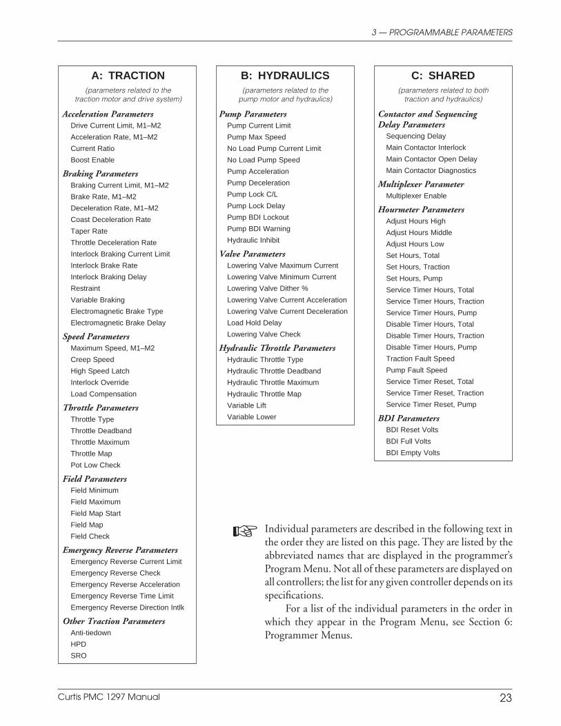
The 1297’s programmable parameters are divided into three groups:
A Traction Parameters
B Hydraulic Parameters
C Shared Parameters
which in turn are divided into subgroups by topic:
A Traction Parameters
— Acceleration— Braking— Speed— Throttle— Field— Emergency reverse— Other traction parameters
B Hydraulic Parameters
— Pump— Valve control— Hydraulic throttle
C Shared Parameters
— Contactor and sequencing delay— Multiplexer (MUX)
— Hourmeters— BDI.
The individual parameters are listed on the next page.
3
Curtis PMC 1297 Manual 23
3 — PROGRAMMABLE PARAMETERS
A: TRACTION(parameters related to the
traction motor and drive system)
Acceleration ParametersDrive Current Limit, M1–M2
Acceleration Rate, M1–M2
Current Ratio
Boost Enable
Braking ParametersBraking Current Limit, M1–M2
Brake Rate, M1–M2
Deceleration Rate, M1–M2
Coast Deceleration Rate
Taper Rate
Throttle Deceleration Rate
Interlock Braking Current Limit
Interlock Brake Rate
Interlock Braking Delay
Restraint
Variable Braking
Electromagnetic Brake Type
Electromagnetic Brake Delay
Speed ParametersMaximum Speed, M1–M2
Creep Speed
High Speed Latch
Interlock Override
Load Compensation
Throttle ParametersThrottle Type
Throttle Deadband
Throttle Maximum
Throttle Map
Pot Low Check
Field ParametersField Minimum
Field Maximum
Field Map Start
Field Map
Field Check
Emergency Reverse ParametersEmergency Reverse Current Limit
Emergency Reverse Check
Emergency Reverse Acceleration
Emergency Reverse Time Limit
Emergency Reverse Direction Intlk
Other Traction ParametersAnti-tiedown
HPD
SRO
B: HYDRAULICS(parameters related to the
pump motor and hydraulics)
Pump ParametersPump Current Limit
Pump Max Speed
No Load Pump Current Limit
No Load Pump Speed
Pump Acceleration
Pump Deceleration
Pump Lock C/L
Pump Lock Delay
Pump BDI Lockout
Pump BDI Warning
Hydraulic Inhibit
Valve ParametersLowering Valve Maximum Current
Lowering Valve Minimum Current
Lowering Valve Dither %
Lowering Valve Current Acceleration
Lowering Valve Current Deceleration
Load Hold Delay
Lowering Valve Check
Hydraulic Throttle ParametersHydraulic Throttle Type
Hydraulic Throttle Deadband
Hydraulic Throttle Maximum
Hydraulic Throttle Map
Variable Lift
Variable Lower
C: SHARED(parameters related to both
traction and hydraulics)
Contactor and SequencingDelay Parameters
Sequencing Delay
Main Contactor Interlock
Main Contactor Open Delay
Main Contactor Diagnostics
Multiplexer ParameterMultiplexer Enable
Hourmeter ParametersAdjust Hours High
Adjust Hours Middle
Adjust Hours Low
Set Hours, Total
Set Hours, Traction
Set Hours, Pump
Service Timer Hours, Total
Service Timer Hours, Traction
Service Timer Hours, Pump
Disable Timer Hours, Total
Disable Timer Hours, Traction
Disable Timer Hours, Pump
Traction Fault Speed
Pump Fault Speed
Service Timer Reset, Total
Service Timer Reset, Traction
Service Timer Reset, Pump
BDI ParametersBDI Reset Volts
BDI Full Volts
BDI Empty Volts
Individual parameters are described in the following text inthe order they are listed on this page. They are listed by theabbreviated names that are displayed in the programmer’sProgram Menu. Not all of these parameters are displayed onall controllers; the list for any given controller depends on itsspecifications.
For a list of the individual parameters in the order inwhich they appear in the Program Menu, see Section 6:Programmer Menus.
Curtis PMC 1297 Manual 24
3A — PROGRAMMABLE TRACTION PARAMETERS: Acceleration
Acceleration Parameters
A. TRACTION PARAMETERS
The various traction parameters adjust the vehicle’s operating characteristics—itsacceleration, braking, speed, and responsiveness. These parameters allow the vehicleto be tailored to a specific application, or to a specific operator’s preferences.
The MultiMode™ feature of the 1297 controller allows operation in twodistinct modes. These two modes can be programmed to provide two different sets ofoperating characteristics, which can be useful for different conditions. For example,Mode 1 could be set up for slow precise indoor maneuvering and Mode 2 for faster,long distance, outdoor travel. There are six parameters that can be individually setin the two modes:
Drive Current Limit, M1–M2Acceleration Rate, M1–M2Brake Current Limit, M1–M2Brake Rate, M1–M2Deceleration Rate, M1–M2Maximum Speed, M1–M2.
It should be noted that the acceleration and braking parameters determinecontroller output and not the actual accelerating/braking time (or distance); thetime (or distance) required to achieve the requested speed is influenced by a varietyof factors—including initial speed, vehicle load, and terrain.
M1–M2, DRIVE C/L
The drive current limit parameter allows adjustment of the maximum currentthe controller will supply to the traction motor during drive operation. Settingthis parameter at a low value reduces the maximum torque applied to the drivesystem by the motor, which may be desirable in Mode 1 if it is configured as aslow speed mode. The drive current limit is adjustable from 50 amps to thecontroller’s full rated drive current. (The full rated drive current depends on thecontroller model; see specifications in Table E-1.)
The drive current limit is tuned as part of the vehicle performanceadjustment process (Section 5).
M1–M2, ACCEL RATE
The acceleration rate defines the time it takes the controller to accelerate from0% output to 100% output when full throttle is requested. A larger valuerepresents a longer acceleration time and a gentler start. Fast starts can beachieved by reducing the acceleration time, i.e., by adjusting the accel rate to asmaller value. The accel rate is adjustable from 0.1 to 3.0 seconds.
The accel rate is tuned as part of the vehicle performance adjustmentprocess (Section 5).
Curtis PMC 1297 Manual 25
CURRENT RATIO
The current ratio parameter defines how much of the programmed drivecurrent will be available to the traction motor at reduced throttle requests. Thecurrent ratio parameter can be set to 1, 2, 3, or 4. These settings correspond tothe following ratios:
SETTING RATIO
1 1 : 12 2 : 13 4 : 14 8 : 1
For example, with the current ratio set at 1 and 20% throttle requested, 20%of the battery voltage and 20% of the drive current will be allowed to flow in themotor (assuming a 50% throttle map setting). If the current ratio is set at 2under these same conditions, 40% of the current will be available; if it is set at3, 80%. The controller will not allow more than the programmed drive current toflow in the motor. If the current ratio is set at 4 with 20% throttle requested, thecontroller will allow only 100% of the drive current and not 160%.
High current ratio values will allow quicker startup response and improvedramp climbing with partial throttle, but may cause too much jumpiness.
The current ratio is tuned as part of the vehicle performance adjustmentprocess (Section 5).
NOTE: Current ratio is only effective in drive; it does not affect regenera-tive braking.
BOOST ENABLE
In situations where the controller detects that the motor is about to stall, theboost enable feature provides a burst of extra torque by briefly applying a highercurrent (120% of the programmed drive current limit). This can be useful foroccasionally getting the vehicle out of a pothole or over an obstacle. If theoperator rocks the vehicle by reversing and rethrottling while in boost, the fieldwill remain at max field to provide the maximum stall torque and minimumdelay time. Boost enable can be programmed On or Off.
Each boost is limited to 6 seconds, followed by a 30 second cool-downperiod, with a total of 15 seconds of boost allowed within each 3 minute period.Performance is more consistent if boost enable is programmed Off.
M1–M2, BRAKE C/L
The braking current limit parameter allows adjustment of the maximumcurrent the controller will supply to the motor during braking. The brakingcurrent limit is adjustable from 50 amps up to the controller’s full rated braking
3A — PROGRAMMABLE TRACTION PARAMETERS: Braking
Braking Parameters
Curtis PMC 1297 Manual 26
current. (The full rated braking current depends on the controller model; seespecifications in Table E-1.)
The braking current limit is tuned as part of the vehicle performanceadjustment process (Section 5).
M1–M2, BRAKE RATE
The braking rate defines the time it takes the controller to increase from 0%braking output to 100% braking output when a new direction is selected. Alarger value represents a longer time and consequently gentler braking. Fasterbraking is achieved by adjusting the braking rate to a smaller value. The brakingrate is adjustable from 0.1 to 3.0 seconds.
M1–M2, DECEL RATE
The deceleration rate defines the time it takes the controller to decelerate from100% output to 0% output. The decel rate determines the vehicle’s brakingcharacteristic for any reduction in throttle that does not include a request for theopposite direction. A lower value represents a faster deceleration and thus ashorter stopping distance. The decel rate is adjustable from 0.1 to 10.0 seconds.
COAST DECEL
The coast deceleration rate defines how quickly the controller reduces it outputto zero when the Pick switch is released. This parameter allows adjustment fordifferent sized vehicles. Lower values represent faster deceleration and thus ashorter coasting distance. The coast decel rate is adjustable from 0.1 to 10.0seconds.
TAPER RATE
The taper rate determines how quickly the vehicle changes direction when theopposite direction is selected. Low taper rate values result in fast and abruptdirection transitions. Higher taper rate values result in slower and smootherdirection transitions. The taper rate is adjustable from 1 to 20.
The taper rate is tuned as part of the vehicle performance adjustmentprocess (Section 5).
THROTTLE DECEL
The throttle deceleration rate parameter adjusts the rate at which the vehicletransitions to braking when throttle is first reduced. If the throttle decel rate isset low, deceleration is initiated abruptly. The transition is smoother if thethrottle decel rate is higher; however, setting the throttle decel parameter too
3A — PROGRAMMABLE TRACTION PARAMETERS: Braking
Curtis PMC 1297 Manual 27
high can cause the vehicle to feel uncontrollable when the throttle is released,as it will continue to drive for a short period. The throttle decel rate is adjustablefrom 0.1 to 1.0 second, with a value of 0.3 or 0.4 working well for most vehicles.
When the armature current goes negative (i.e., at the point when positivetorque transitions to negative torque), the normal decel rate goes into effect.
INT BRAKE C/L
If the interlock switch is opened while the vehicle is being driven, the controllerwill send braking current to the motor. This braking—which is called interlockbraking—greatly reduces wear on the vehicle’s electromagnetic brake and alsoenables the vehicle to meet more stringent stopping distance requirements. Theinterlock braking current limit parameter allows adjustment of the maximumbraking current the controller will supply to the motor during interlock braking.The interlock braking current limit is adjustable from 50 amps up to thecontroller’s full rated braking current. (The full rated braking current dependson the controller model; see specifications in Table E-1.)
INT BRAKE RATE
The interlock braking rate parameter defines the time it takes the controller toincrease from 0% braking output to 100% braking output when interlockbraking is initiated. The interlock braking rate is adjustable from 0.0 to 3.0seconds.
INT BRAKE DLY
The interlock braking delay feature allows the interlock switch to be cycledwithin a set time (the braking delay), thus preventing inadvertent activation ofinterlock braking. This feature is especially useful in applications where theinterlock switch may bounce or be momentarily cycled during operation. Theinterlock braking delay parameter can be set from 0.0 to 30.0 seconds, with zerocorresponding to no delay.
RESTRAINT
Because the 1297 controller is configured to provide regenerative braking, overspeedcauses the controller to create a braking current and thus limit or “restrain” theoverspeed condition. The restraint parameter determines how strongly the control-ler tries to limit the vehicle speed to the existing throttle setting. It is applicablewhen throttle is reduced or when the vehicle begins to travel downhill.
At zero throttle, the restraint function tries to keep the motor at zero speed,which helps hold the vehicle from running away down ramps. The higher therestraint value, the stronger the braking force applied to the motor and the
3A — PROGRAMMABLE TRACTION PARAMETERS: Braking
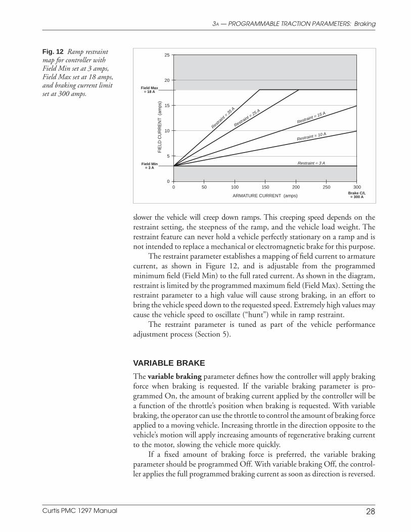
Curtis PMC 1297 Manual 28
slower the vehicle will creep down ramps. This creeping speed depends on therestraint setting, the steepness of the ramp, and the vehicle load weight. Therestraint feature can never hold a vehicle perfectly stationary on a ramp and isnot intended to replace a mechanical or electromagnetic brake for this purpose.
The restraint parameter establishes a mapping of field current to armaturecurrent, as shown in Figure 12, and is adjustable from the programmedminimum field (Field Min) to the full rated current. As shown in the diagram,restraint is limited by the programmed maximum field (Field Max). Setting therestraint parameter to a high value will cause strong braking, in an effort tobring the vehicle speed down to the requested speed. Extremely high values maycause the vehicle speed to oscillate (“hunt”) while in ramp restraint.
The restraint parameter is tuned as part of the vehicle performanceadjustment process (Section 5).
VARIABLE BRAKE
The variable braking parameter defines how the controller will apply brakingforce when braking is requested. If the variable braking parameter is pro-grammed On, the amount of braking current applied by the controller will bea function of the throttle’s position when braking is requested. With variablebraking, the operator can use the throttle to control the amount of braking forceapplied to a moving vehicle. Increasing throttle in the direction opposite to thevehicle’s motion will apply increasing amounts of regenerative braking currentto the motor, slowing the vehicle more quickly.
If a fixed amount of braking force is preferred, the variable brakingparameter should be programmed Off. With variable braking Off, the control-ler applies the full programmed braking current as soon as direction is reversed.
3A — PROGRAMMABLE TRACTION PARAMETERS: Braking
ARMATURE CURRENT (amps)
FIE
LD C
UR
RE
NT
(am
ps)
300250200150100500
25
20
15
10
5
0
Field Max= 18 A
Field Min= 3 A
Brake C/L= 300 A
Restra
int = 35
A
Restraint =
25 A
Restraint = 15 A
Restraint = 10 A
Restraint = 3 A
Fig. 12 Ramp restraintmap for controller withField Min set at 3 amps,Field Max set at 18 amps,and braking current limitset at 300 amps.
Curtis PMC 1297 Manual 29
3A — PROGRAMMABLE TRACTION PARAMETERS: Braking
E-M BRAKE TYPE
The electromagnetic brake type parameter configures the low side brake driverat J1 Pin 20. Driver output is rated at 2 amps and is monitored for overcurrentfaults. An internal diode provides coil suppression through the KSI input (J1 Pin 1).The electromagnetic brake driver can be programmed to operate in any of theconfigurations (i.e., options 0 through 4) described in Table 2.
E-M BRAKE DLY
The electromagnetic brake driver open delay parameter allows a delay afterthe interlock switch has been opened before the brake driver drops out. Thedelay is useful for maintaining braking power for a short time after the interlockswitch has been opened. This parameter is adjustable from 0.0 to 30.0 seconds.When set to zero, there is no delay and the brake driver opens as soon as theinterlock switch is opened and the sequencing delay expires. This parameter isnot valid when brake driver option 0 is selected (see Table 2).
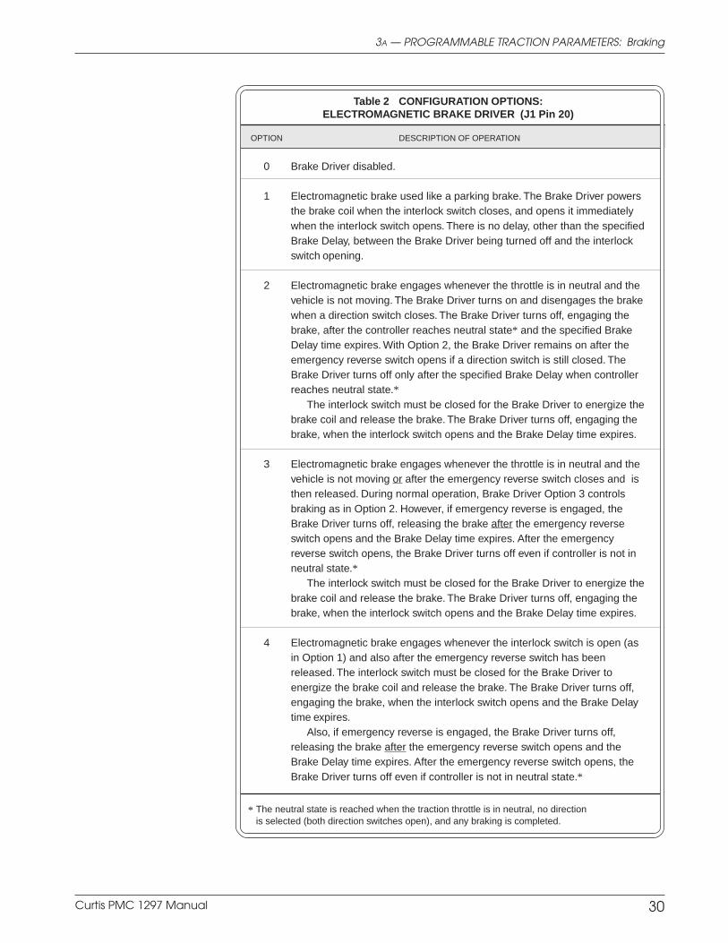
Curtis PMC 1297 Manual 30
3A — PROGRAMMABLE TRACTION PARAMETERS: Braking
Table 2 CONFIGURATION OPTIONS:ELECTROMAGNETIC BRAKE DRIVER (J1 Pin 20)
OPTION DESCRIPTION OF OPERATION
0 Brake Driver disabled.
1 Electromagnetic brake used like a parking brake. The Brake Driver powersthe brake coil when the interlock switch closes, and opens it immediatelywhen the interlock switch opens. There is no delay, other than the specifiedBrake Delay, between the Brake Driver being turned off and the interlockswitch opening.
2 Electromagnetic brake engages whenever the throttle is in neutral and thevehicle is not moving. The Brake Driver turns on and disengages the brakewhen a direction switch closes. The Brake Driver turns off, engaging thebrake, after the controller reaches neutral state* and the specified BrakeDelay time expires. With Option 2, the Brake Driver remains on after theemergency reverse switch opens if a direction switch is still closed. TheBrake Driver turns off only after the specified Brake Delay when controllerreaches neutral state.*
The interlock switch must be closed for the Brake Driver to energize thebrake coil and release the brake. The Brake Driver turns off, engaging thebrake, when the interlock switch opens and the Brake Delay time expires.
3 Electromagnetic brake engages whenever the throttle is in neutral and thevehicle is not moving or after the emergency reverse switch closes and isthen released. During normal operation, Brake Driver Option 3 controlsbraking as in Option 2. However, if emergency reverse is engaged, theBrake Driver turns off, releasing the brake after the emergency reverseswitch opens and the Brake Delay time expires. After the emergencyreverse switch opens, the Brake Driver turns off even if controller is not inneutral state.*
The interlock switch must be closed for the Brake Driver to energize thebrake coil and release the brake. The Brake Driver turns off, engaging thebrake, when the interlock switch opens and the Brake Delay time expires.
4 Electromagnetic brake engages whenever the interlock switch is open (asin Option 1) and also after the emergency reverse switch has beenreleased. The interlock switch must be closed for the Brake Driver toenergize the brake coil and release the brake. The Brake Driver turns off,engaging the brake, when the interlock switch opens and the Brake Delaytime expires.
Also, if emergency reverse is engaged, the Brake Driver turns off,releasing the brake after the emergency reverse switch opens and theBrake Delay time expires. After the emergency reverse switch opens, theBrake Driver turns off even if controller is not in neutral state.*
* The neutral state is reached when the traction throttle is in neutral, no directionis selected (both direction switches open), and any braking is completed.
Curtis PMC 1297 Manual 31
3A — PROGRAMMABLE TRACTION PARAMETERS: Speed
M1–M2, MAX SPEED
The maximum speed parameter defines the maximum controller voltageoutput at full throttle. The maximum speed parameter is adjustable from 0% to100% of full output.
The maximum speed is tuned as part of the vehicle performance adjust-ment process (Section 5).
CREEP SPEED
The creep speed parameter defines the initial controller output generated whena direction is first selected. No applied throttle is necessary for the vehicle toenter the creep mode, only a direction signal. The controller maintains creep speeduntil the throttle is rotated out of the throttle deadband (typically 10% of throttle).
Creep speed is adjustable from 0% to 25% of the controller duty cycle. Formost applications, the default setting of 0% is appropriate. For heavy vehicles,however, increasing the creep speed may improve controllability by reducingthe amount of throttle required to start the vehicle moving. In any case, thecreep speed should always be set low enough so there is some neutral deadbandbefore the vehicle starts to move and it should never be set so high the vehicleis moving too fast when the throttle returns to small values just above the deadband.
NOTE: The programmed creep speed is not displayed as the “Throttle %”value in the programmer’s Test Menu when a direction is selected and zerothrottle is applied; only the 0% throttle command is displayed.
H/S LATCH
The high speed latch parameter is only applicable when the mode switch is amomentary switch. When the high speed latch parameter is programmed On,it allows the mode switch to be “latched” in the M2 position (which is typicallythe high speed position) without the operator having to keep it pressed in. Inother words, it makes the momentary switch function as a pushbutton latchingswitch. The switch automatically “unlatches” when the vehicle changes direc-tion, and must be re-latched if desired in the new direction.
CAUTION: When the vehicle is traveling in high speed mode with the highspeed latch parameter programmed On, emergency reverse is disabled.
INT OVERRIDE
The interlock override parameter, when programmed On, allows the vehicle tobe driven with the interlock switch open. The interlock override feature is usefulin situations where it is necessary to move the vehicle but there is not room tolower the tiller—for example, in a corner.
Speed Parameters
C A U T I O N

Curtis PMC 1297 Manual 32
If the interlock override feature is desired, you will probably want toconfigure M2 (mode switch closed) as the slow speed mode, and M1 (modeswitch open) as the high speed mode. This is opposite of the typical setup. NOTE:The interlock override feature and the high speed latch parameters are mutuallyexclusive; you cannot have both.
To initiate override, close the mode switch (M2) while the vehicle isstopped with the interlock switch open.
To resume normal operation, the interlock or KSI must be cycled.
LOAD COMP
The load compensation parameter actively adjusts the applied motor voltageas a function of motor load current. This results in more constant vehicle speedsover variations in driving surface (ramps, rough terrain, etc.) without the vehicleoperator constantly adjusting the throttle position; it also helps equalize loadedand unloaded vehicle speeds. The load compensation parameter is adjustablefrom 0 to 25% of the controller’s PWM output. High values will cause thecontroller to be more aggressive in attempting to maintain vehicle speed.However, too much load compensation can result in jerky vehicle starts andspeed oscillation (“hunting”) when the vehicle is unloaded.
The load compensation parameter is tuned as part of the vehicle perfor-mance adjustment process (Section 5).
3A — PROGRAMMABLE TRACTION PARAMETERS: Speed
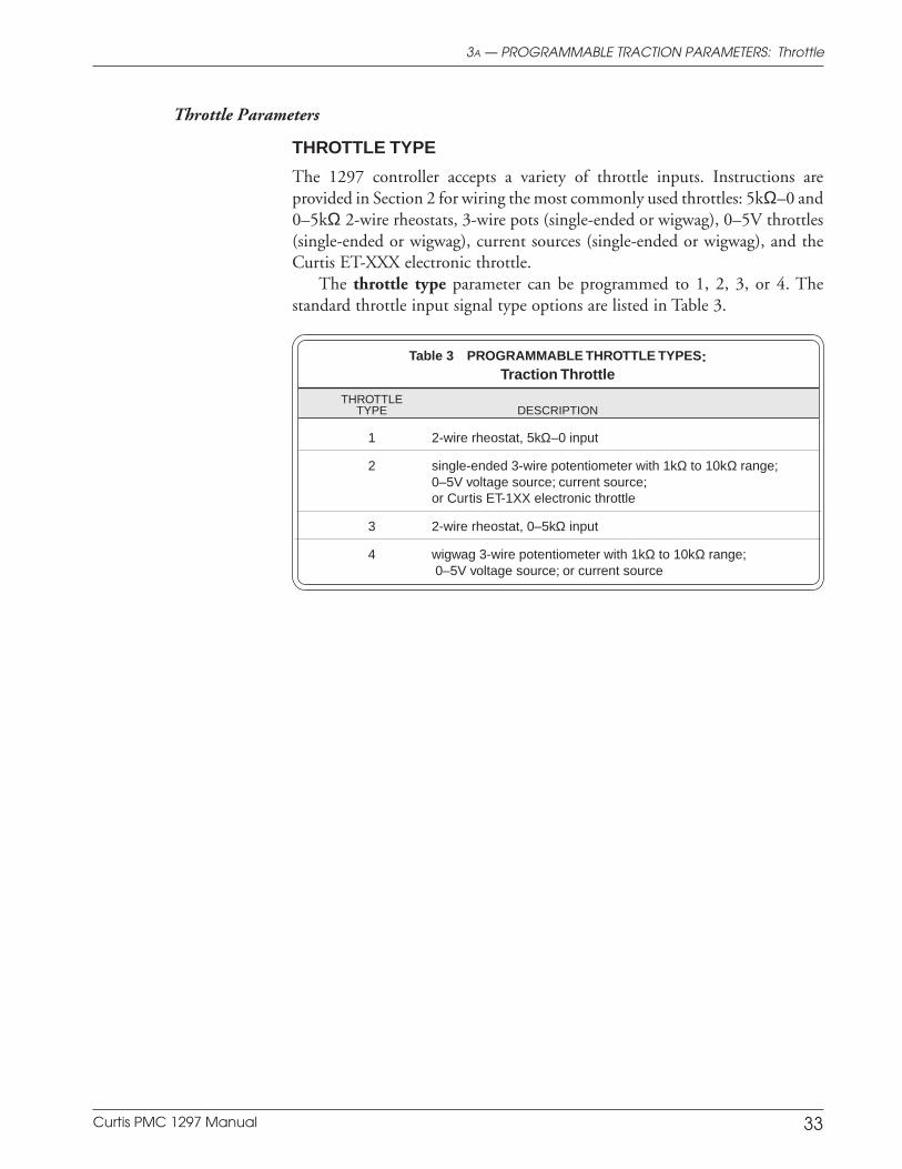
Curtis PMC 1297 Manual 33
THROTTLE TYPE
The 1297 controller accepts a variety of throttle inputs. Instructions areprovided in Section 2 for wiring the most commonly used throttles: 5kΩ–0 and0–5kΩ 2-wire rheostats, 3-wire pots (single-ended or wigwag), 0–5V throttles(single-ended or wigwag), current sources (single-ended or wigwag), and theCurtis ET-XXX electronic throttle.
The throttle type parameter can be programmed to 1, 2, 3, or 4. Thestandard throttle input signal type options are listed in Table 3.
Table 3 PROGRAMMABLE THROTTLE TYPES:Traction Throttle
THROTTLETYPE DESCRIPTION
1 2-wire rheostat, 5kΩ–0 input
2 single-ended 3-wire potentiometer with 1kΩ to 10kΩ range;0–5V voltage source; current source;or Curtis ET-1XX electronic throttle
3 2-wire rheostat, 0–5kΩ input
4 wigwag 3-wire potentiometer with 1kΩ to 10kΩ range; 0–5V voltage source; or current source
3A — PROGRAMMABLE TRACTION PARAMETERS: Throttle
Throttle Parameters
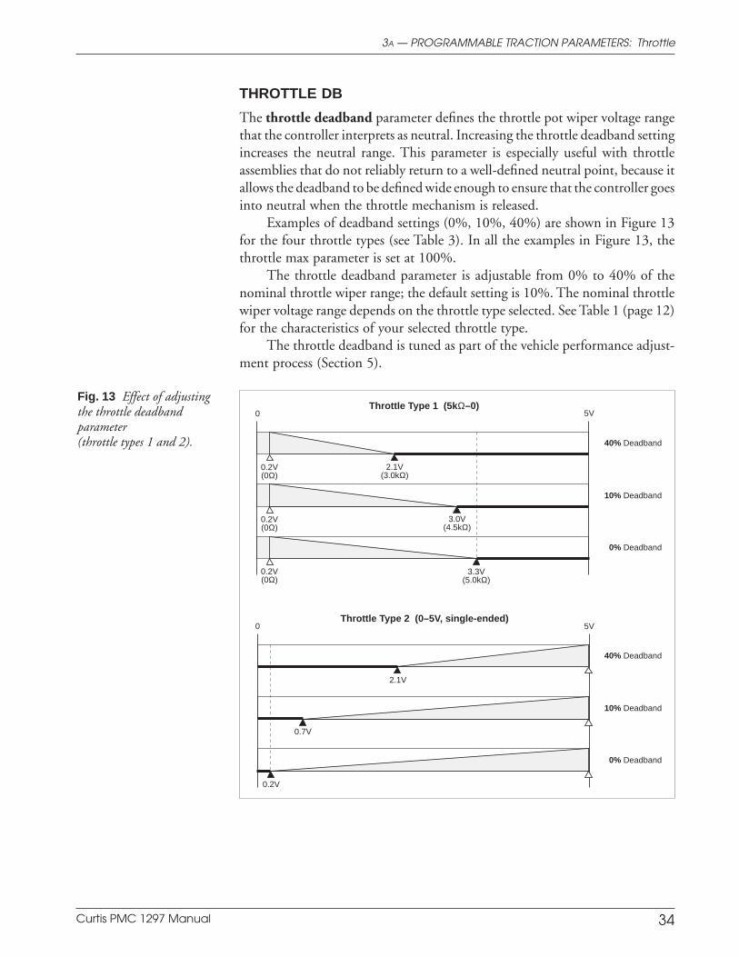
Curtis PMC 1297 Manual 34
3A — PROGRAMMABLE TRACTION PARAMETERS: Throttle
Throttle Type 2 (0–5V, single-ended)
Throttle Type 1 (5kΩ–0)
5V 0
0.2V
40% Deadband
10% Deadband
0% Deadband
0.7V
2.1V
5V 0
3.3V(5.0kΩ)
40% Deadband
10% Deadband
0% Deadband
3.0V(4.5kΩ)
2.1V(3.0kΩ)
0.2V(0Ω)
0.2V(0Ω)
0.2V(0Ω)
Fig. 13 Effect of adjustingthe throttle deadbandparameter(throttle types 1 and 2).
THROTTLE DB
The throttle deadband parameter defines the throttle pot wiper voltage rangethat the controller interprets as neutral. Increasing the throttle deadband settingincreases the neutral range. This parameter is especially useful with throttleassemblies that do not reliably return to a well-defined neutral point, because itallows the deadband to be defined wide enough to ensure that the controller goesinto neutral when the throttle mechanism is released.
Examples of deadband settings (0%, 10%, 40%) are shown in Figure 13for the four throttle types (see Table 3). In all the examples in Figure 13, thethrottle max parameter is set at 100%.
The throttle deadband parameter is adjustable from 0% to 40% of thenominal throttle wiper range; the default setting is 10%. The nominal throttlewiper voltage range depends on the throttle type selected. See Table 1 (page 12)for the characteristics of your selected throttle type.
The throttle deadband is tuned as part of the vehicle performance adjust-ment process (Section 5).

Curtis PMC 1297 Manual 35
Fig. 13, cont’d Effect ofadjusting the throttledeadband parameter(throttle types 3 and 4).
Throttle Type 3 (0–5kΩ)
Throttle Type 4 (0–5V, wigwag)
5V 0
0.2V(0Ω)
40% Deadband
10% Deadband
0% Deadband
0.5V(450Ω)
1.4V(2.0kΩ)
Notes: Voltages shown are at the pot wiper relative to B-.
For throttle types 1 and 3, the deadband points aredefined in terms of the nominal 5kΩ pot resistance.Using a pot of greater or lesser resistance will givedifferent values for the deadband points.
Throttle Max parameter set at 100%.
3.3V(5.0kΩ)
3.3V(5.0kΩ)
3.3V(5.0kΩ)
KEY
100%Neutral
DeadbandController
Output0%
5V 0
0.5V
40% Deadband
10% Deadband
0% Deadband
2.7V
3.3V 4.5V
4.5V
4.5V2.5V
0.5V
0.5V
2.3V
1.7V
3A — PROGRAMMABLE TRACTION PARAMETERS: Throttle
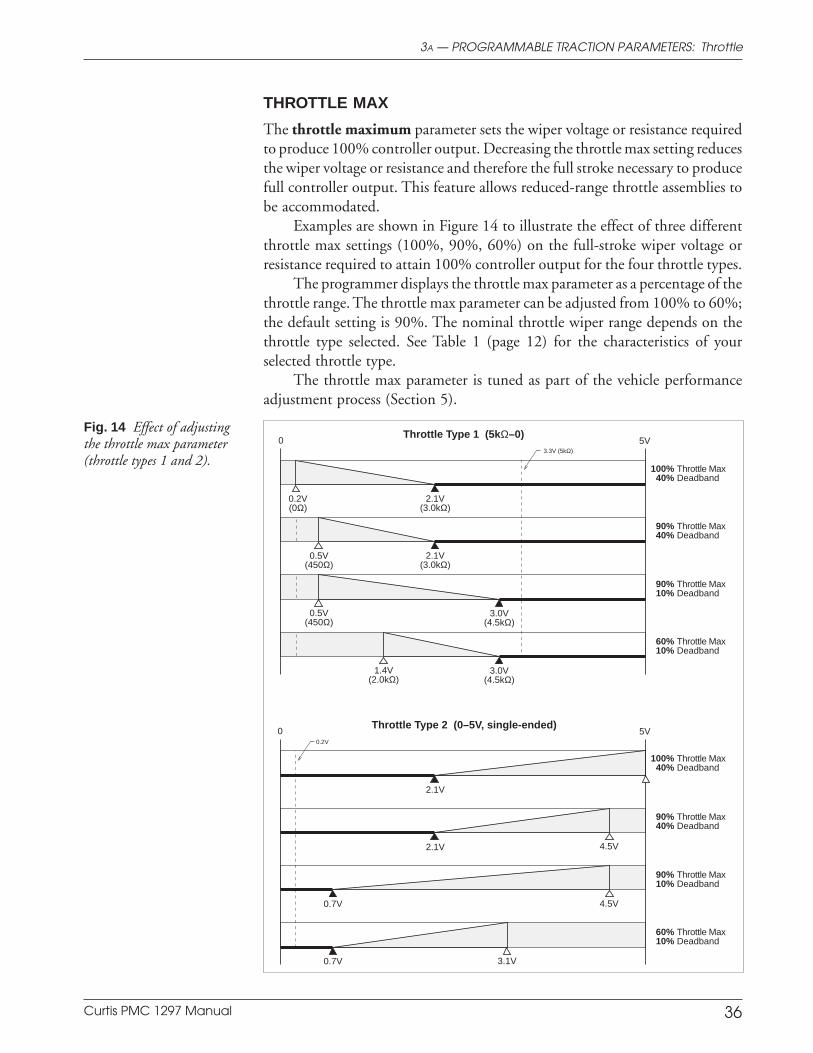
Curtis PMC 1297 Manual 36
THROTTLE MAX
The throttle maximum parameter sets the wiper voltage or resistance requiredto produce 100% controller output. Decreasing the throttle max setting reducesthe wiper voltage or resistance and therefore the full stroke necessary to producefull controller output. This feature allows reduced-range throttle assemblies tobe accommodated.
Examples are shown in Figure 14 to illustrate the effect of three differentthrottle max settings (100%, 90%, 60%) on the full-stroke wiper voltage orresistance required to attain 100% controller output for the four throttle types.
The programmer displays the throttle max parameter as a percentage of thethrottle range. The throttle max parameter can be adjusted from 100% to 60%;the default setting is 90%. The nominal throttle wiper range depends on thethrottle type selected. See Table 1 (page 12) for the characteristics of yourselected throttle type.
The throttle max parameter is tuned as part of the vehicle performanceadjustment process (Section 5).
Fig. 14 Effect of adjustingthe throttle max parameter(throttle types 1 and 2).
Throttle Type 2 (0–5V, single-ended)
Throttle Type 1 (5kΩ–0)
0 5V
2.1V
100% Throttle Max40% Deadband
0.7V 4.5V
0.7V 3.1V
2.1V 4.5V
90% Throttle Max40% Deadband
90% Throttle Max10% Deadband
60% Throttle Max10% Deadband
0 5V
2.1V(3.0kΩ)
0.2V(0Ω)
100% Throttle Max40% Deadband
3.0V(4.5kΩ)
1.4V(2.0kΩ)
0.5V(450Ω)
90% Throttle Max40% Deadband
90% Throttle Max10% Deadband
60% Throttle Max10% Deadband
0.5V(450Ω)
2.1V(3.0kΩ)
3.0V(4.5kΩ)
3.3V (5kΩ)
0.2V
3A — PROGRAMMABLE TRACTION PARAMETERS: Throttle
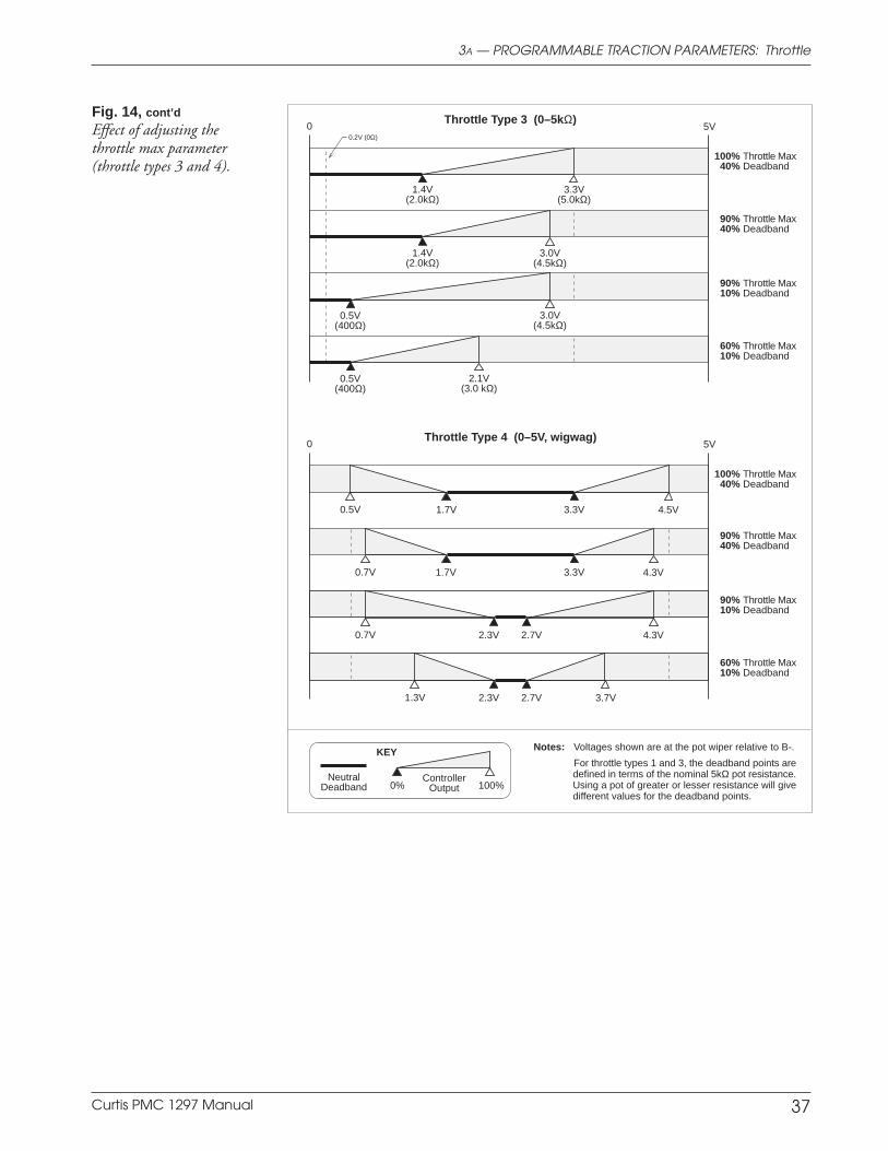
Curtis PMC 1297 Manual 37
Fig. 14, cont’d
Effect of adjusting thethrottle max parameter(throttle types 3 and 4).
Throttle Type 3 (0–5kΩ)
Throttle Type 4 (0–5V, wigwag)
0 5V
1.4V(2.0kΩ)
3.3V(5.0kΩ)
100% Throttle Max40% Deadband
0.5V(400Ω)
2.1V(3.0 kΩ)
3.0V(4.5kΩ)
90% Throttle Max40% Deadband
90% Throttle Max10% Deadband
60% Throttle Max10% Deadband
Notes: Voltages shown are at the pot wiper relative to B-.
For throttle types 1 and 3, the deadband points aredefined in terms of the nominal 5kΩ pot resistance.Using a pot of greater or lesser resistance will givedifferent values for the deadband points.
KEY
100%Neutral
DeadbandController
Output0%
1.4V(2.0kΩ)
0.5V(400Ω)
3.0V(4.5kΩ)
0 5V
100% Throttle Max40% Deadband
90% Throttle Max40% Deadband
90% Throttle Max10% Deadband
60% Throttle Max10% Deadband
3.3V 4.5V0.5V 1.7V
3.3V 4.3V0.7V 1.7V
2.7V 4.3V0.7V 2.3V
2.7V 3.7V1.3V 2.3V
0.2V (0Ω)
3A — PROGRAMMABLE TRACTION PARAMETERS: Throttle
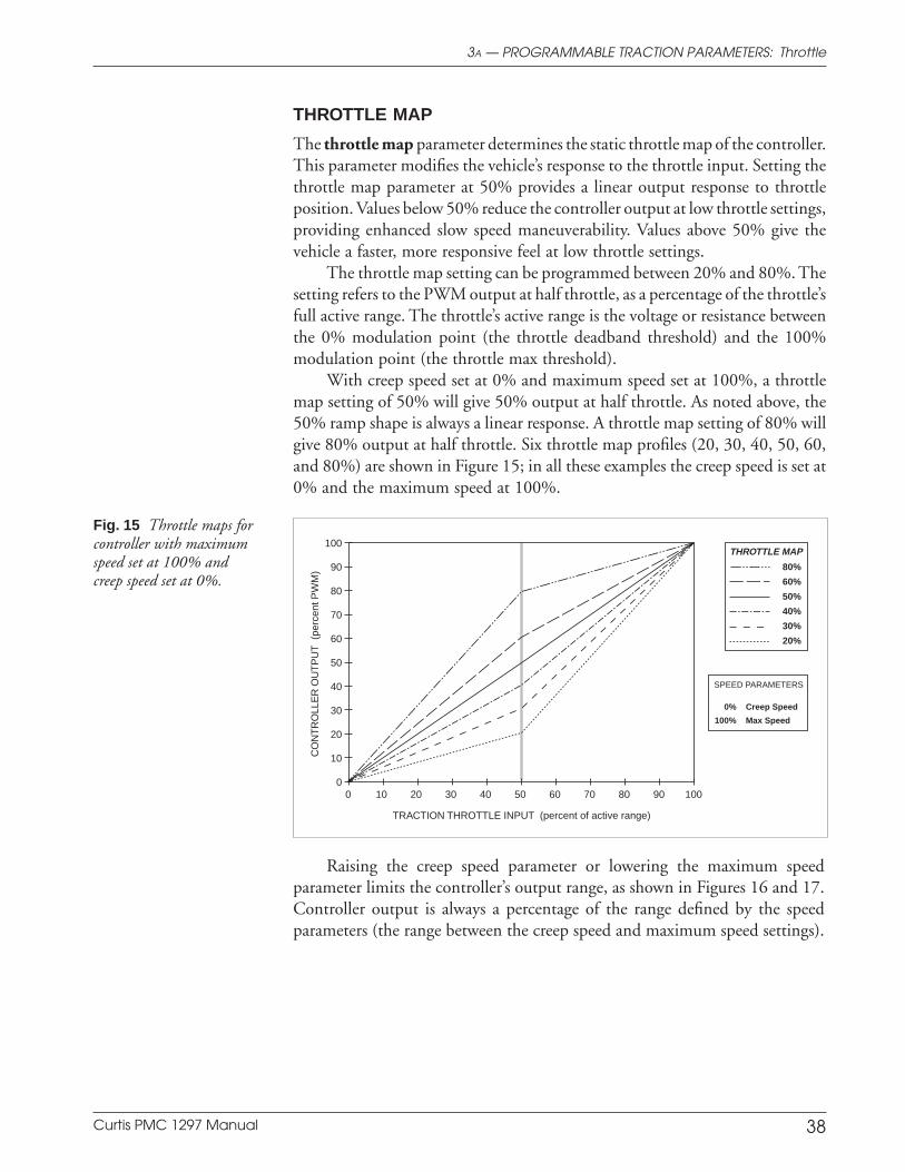
Curtis PMC 1297 Manual 38
THROTTLE MAP
The throttle map parameter determines the static throttle map of the controller.This parameter modifies the vehicle’s response to the throttle input. Setting thethrottle map parameter at 50% provides a linear output response to throttleposition. Values below 50% reduce the controller output at low throttle settings,providing enhanced slow speed maneuverability. Values above 50% give thevehicle a faster, more responsive feel at low throttle settings.
The throttle map setting can be programmed between 20% and 80%. Thesetting refers to the PWM output at half throttle, as a percentage of the throttle’sfull active range. The throttle’s active range is the voltage or resistance betweenthe 0% modulation point (the throttle deadband threshold) and the 100%modulation point (the throttle max threshold).
With creep speed set at 0% and maximum speed set at 100%, a throttlemap setting of 50% will give 50% output at half throttle. As noted above, the50% ramp shape is always a linear response. A throttle map setting of 80% willgive 80% output at half throttle. Six throttle map profiles (20, 30, 40, 50, 60,and 80%) are shown in Figure 15; in all these examples the creep speed is set at0% and the maximum speed at 100%.
3A — PROGRAMMABLE TRACTION PARAMETERS: Throttle
Fig. 15 Throttle maps forcontroller with maximumspeed set at 100% andcreep speed set at 0%.
TRACTION THROTTLE INPUT (percent of active range)
CO
NT
RO
LLE
R O
UT
PU
T (
perc
ent P
WM
) 80%
60%
50%
40%
30%
20%
THROTTLE MAP100
90
80
70
60
50
40
30
20
10
0100908070605040302010 0
SPEED PARAMETERS
0% Creep Speed
100% Max Speed
Raising the creep speed parameter or lowering the maximum speedparameter limits the controller’s output range, as shown in Figures 16 and 17.Controller output is always a percentage of the range defined by the speedparameters (the range between the creep speed and maximum speed settings).

Curtis PMC 1297 Manual 39
In Figure 16, the creep speed is increased to 10% and the maximum speedis left at 100%, resulting in a controller output range of 90%. With these speedsettings, a 50% throttle map will result in 55% output (45% + 10%) at halfthrottle.
Fig. 16 Throttle maps forcontroller with maximumspeed set at 100% andcreep speed set at 10%.
Fig. 17 Throttle maps forcontroller with maximumspeed set at 90% andcreep speed set at 0%.
In Figure 17, the maximum speed is decreased to 90% and the creep speedis left at 0%; again, the controller output range is 90%. With these speedsettings, a 50% throttle map will result in 45% output at half throttle.
TRACTION THROTTLE INPUT (percent of active range)
80%
60%
50%
40%
30%
20%
THROTTLE MAP100
90
80
70
60
50
40
30
20
10
0100908070605040302010 0
SPEED PARAMETERS
10% Creep Speed
100% Max Speed
CO
NT
RO
LLE
R O
UT
PU
T (
perc
ent P
WM
)
TRACTION THROTTLE INPUT (percent of active range)
CO
NT
RO
LLE
R O
UT
PU
T (
perc
ent P
WM
) 80%
60%
50%
40%
30%
20%
THROTTLE MAP100
90
80
70
60
50
40
30
20
10
0100908070605040302010 0
SPEED PARAMETERS
0% Creep Speed
90% Max Speed
The throttle map operates within the window established by the CreepSpeed, Max Speed, Throttle Deadband, and Throttle Max parameters, asshown in Figure 18. Creep Speed and Max Speed define the controller’s outputrange, while Throttle Deadband and Throttle Max define the throttle’s active
3A — PROGRAMMABLE TRACTION PARAMETERS: Throttle
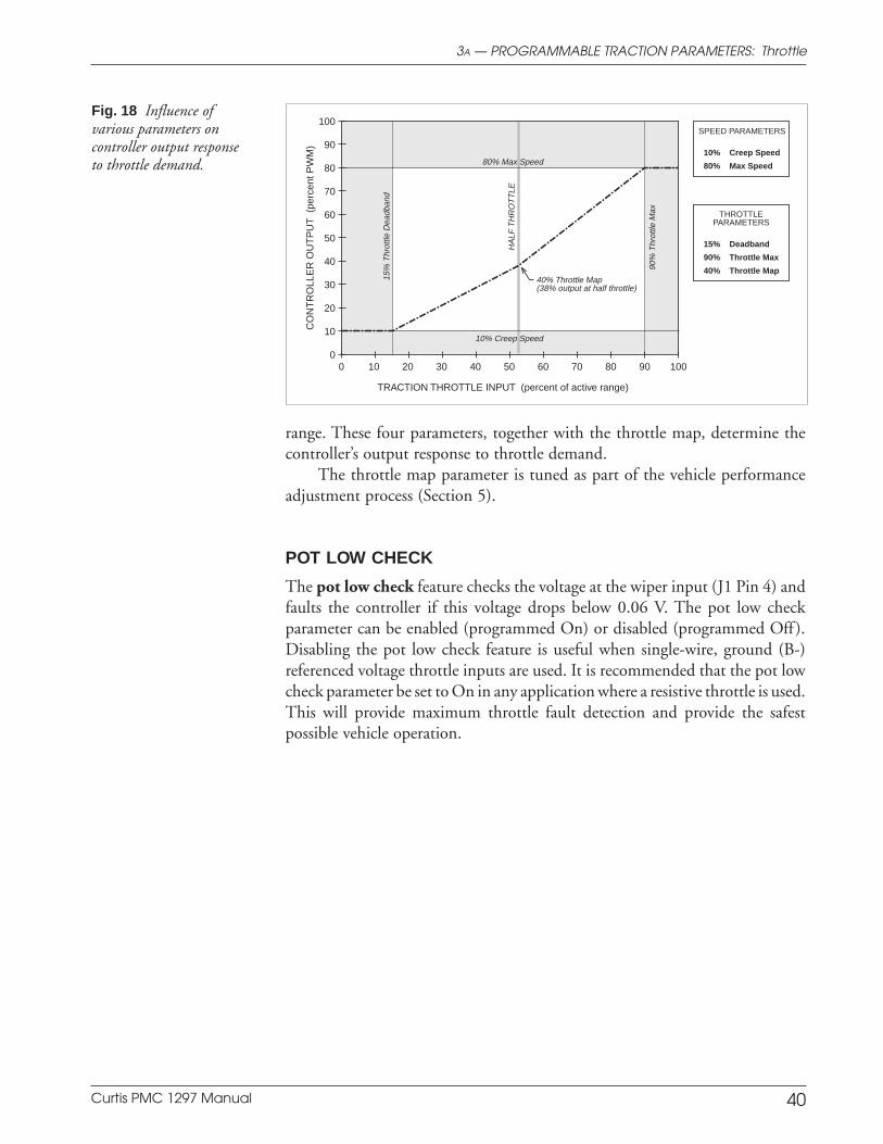
Curtis PMC 1297 Manual 40
range. These four parameters, together with the throttle map, determine thecontroller’s output response to throttle demand.
The throttle map parameter is tuned as part of the vehicle performanceadjustment process (Section 5).
POT LOW CHECK
The pot low check feature checks the voltage at the wiper input (J1 Pin 4) andfaults the controller if this voltage drops below 0.06 V. The pot low checkparameter can be enabled (programmed On) or disabled (programmed Off ).Disabling the pot low check feature is useful when single-wire, ground (B-)referenced voltage throttle inputs are used. It is recommended that the pot lowcheck parameter be set to On in any application where a resistive throttle is used.This will provide maximum throttle fault detection and provide the safestpossible vehicle operation.
Fig. 18 Influence ofvarious parameters oncontroller output responseto throttle demand.
TRACTION THROTTLE INPUT (percent of active range)
CO
NT
RO
LLE
R O
UT
PU
T (
perc
ent P
WM
)
100908070605040302010 0
SPEED PARAMETERS
10% Creep Speed
80% Max Speed
THROTTLEPARAMETERS
15% Deadband
90% Throttle Max
40% Throttle Map
80% Max Speed
40% Throttle Map(38% output at half throttle)
10% Creep Speed
15%
Thr
ottle
Dea
dban
d
90%
Thr
ottle
Max
HA
LF T
HR
OT
TLE
100
90
80
70
60
50
40
30
20
10
0
3A — PROGRAMMABLE TRACTION PARAMETERS: Throttle
Curtis PMC 1297 Manual 41
FIELD MIN
The minimum field current limit parameter defines the minimum allowedfield winding current. The minimum field current limit setting determines thevehicle’s maximum speed. Field Min can be adjusted from 2 amps up to theprogrammed Field Max value.
The Field Min parameter is tuned as part of the vehicle performanceadjustment process (Section 5).
FIELD MAX
The maximum field current limit parameter defines the maximum allowedfield winding current. The maximum field current limit setting determines thevehicle’s maximum torque and limits the power dissipation in the field windingitself. Field Max can be adjusted from the programmed Field Min value up tothe controller’s full rated field current. (The full rated field current depends onthe controller model; see specifications in Table E-1.)
The Field Max parameter is tuned as part of the vehicle performanceadjustment process (Section 5).
FLD MAP START
The field map start parameter defines the armature current at which the fieldmap starts to increase; it is adjustable from 25 amps up to the controller’s fullrated armature current value. (The full rated armature current depends on thecontroller model; see specifications in Table E-1.)
The field map start parameter is used to equalize the vehicle’s maximumspeed when loaded and unloaded. Increasing the field map start parametervalue will increase the maximum load weight that the vehicle can carry whilemaintaining maximum speed on a level surface.
The field map start parameter is tuned as part of the vehicle performanceadjustment process (Section 5).
FIELD MAP
The field map parameter controls how much field current is applied for a givenarmature current. This parameter, along with the other field current parameters(Field Min, Field Max, and Field Map Start), allows the OEM to set the vehicle’sspeed and power performance characteristics.
The field map parameter is set as a percentage of the field current betweenthe Field Min and Field Max values. As shown in Figure 19, the field mapparameter adjusts the field current at a point halfway between the programmedField Map Start current and the full armature current (which is the controller’s
3A — PROGRAMMABLE TRACTION PARAMETERS: Field
Field Parameters
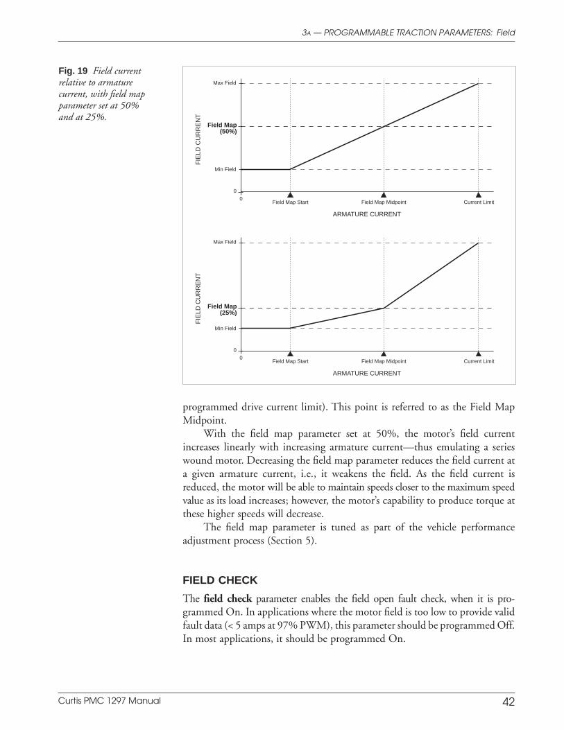
Curtis PMC 1297 Manual 42
3A — PROGRAMMABLE TRACTION PARAMETERS: Field
Fig. 19 Field currentrelative to armaturecurrent, with field mapparameter set at 50%and at 25%.
ARMATURE CURRENT
FIE
LD C
UR
RE
NT
Field Map Start Field Map Midpoint Current Limit0
0
Min Field
Max Field
Field Map(50%)
ARMATURE CURRENT
FIE
LD C
UR
RE
NT
Field Map Start Field Map Midpoint Current Limit0
0
Min Field
Max Field
Field Map(25%)
programmed drive current limit). This point is referred to as the Field MapMidpoint.
With the field map parameter set at 50%, the motor’s field currentincreases linearly with increasing armature current—thus emulating a serieswound motor. Decreasing the field map parameter reduces the field current ata given armature current, i.e., it weakens the field. As the field current isreduced, the motor will be able to maintain speeds closer to the maximum speedvalue as its load increases; however, the motor’s capability to produce torque atthese higher speeds will decrease.
The field map parameter is tuned as part of the vehicle performanceadjustment process (Section 5).
FIELD CHECK
The field check parameter enables the field open fault check, when it is pro-grammed On. In applications where the motor field is too low to provide validfault data (< 5 amps at 97% PWM), this parameter should be programmed Off.In most applications, it should be programmed On.
Curtis PMC 1297 Manual 43
Emergency R everse Parameters
3A — PROGRAMMABLE TRACTION PARAMETERS: Emergency Reverse
EMR REV C/L
The emergency reverse current limit parameter defines the maximum brakingcurrent provided through the motor when the optional emergency reversefunction is engaged. The emergency reverse current limit is adjustable from 50amps up to the controller’s full rated braking current. (The full rated brakingcurrent depends on the controller model; see specifications in Table E-1.)
EMR REV CHECK
The emergency reverse check parameter is applicable only when the emergencyreverse feature is being used in the application. If emergency reverse is not beingused, this parameter should be set to Off.
When enabled (programmed On), the emergency reverse check tests forcontinuity from the emergency reverse check output (J1 Pin 9) to the emer-gency reverse input (J1 Pin 6). Therefore, the emergency reverse wiring shouldbe connected as closely as possible to the controller side of the emergencyreverse switch. The recommended wiring is shown in Figures 3 and 4, pages 8and 10.
EMR REV ACCEL
The emergency reverse acceleration rate parameter defines the time it takes thecontroller to accelerate from 0% to 100% output in the opposite direction whenemergency reverse is activated. Larger values represent a longer acceleration timeand therefore a gentler response. More abrupt response can be achieved byreducing the acceleration time, i.e., by setting the accel rate to a lower value.
The emergency reverse accel rate is adjustable from 0.0 to 3.0 seconds.
EMR REV TIME LIMIT
The emergency reverse time limit parameter can be used to provide a 5 secondtime limit on emergency reversing. If this parameter is programmed On,emergency reversing will stop after 5 seconds even if the emergency reversebutton is still being pushed in; at the end of this 5 second period, the controllerwill set the drive output to zero. If this parameter is programmed Off, emergencyreversing will continue as long as the emergency reverse button is pushed in.
EMR DIR INT
As soon as the emergency reverse button is released, the controller sets the driveoutput to zero regardless of whether a direction or throttle is still beingrequested. The emergency reverse direction interlock parameter defines how
Curtis PMC 1297 Manual 44
the controller will return to normal operation from this point. If the emergencyreverse direction interlock parameter is set to On, the operator can either openboth direction switches or cycle the interlock switch to enable normal operation.With the parameter set to Off, the only way for the operator to resume normaloperation is by cycling the interlock switch.
ANTI-TIEDOWN
The anti-tiedown feature prevents operators from taping or “tying down” themode switch in order to operate permanently in Mode 2 (which is typically thehigh speed mode). Upon startup, when the interlock switch is first closed, theanti-tiedown feature checks which mode is selected. If the mode switch isrequesting Mode 2 (i.e., switch closed), the controller will ignore the request anddefault to Mode 1. The controller will remain in Mode 1 until the mode switch isreleased and reactivated. Anti-tiedown can be programmed On or Off.
HPD
The high pedal disable (HPD) feature prevents the vehicle from driving themotor if the controller is turned on when greater than 25% throttle is applied.In addition to providing routine smooth starts, HPD also protects againstaccidental sudden starts if problems in the throttle linkage (e.g., bent parts,broken return spring) give a throttle input signal to the controller even with thethrottle released.
If the operator attempts to start the vehicle with the throttle alreadyapplied, the controller will inhibit output to the motor until the throttle isreduced below 25%. For the vehicle to run, the controller must receive a KSIinput—or a KSI input and an interlock input—before receiving a throttle inputgreater than 25%. Either type of HPD (HPD based on KSI input alone orHPD based on KSI plus interlock inputs) can be selected via the programmer.HPD can also be disabled. To meet EEC requirements, the HPD feature mustbe programmed to Type 1 or Type 2.
Sequencing delay (see page 57) can be used to provide a brief delay beforeHPD inhibits the controller output, if desired.
No HPD (Type 0)
HPD function is disabled.
Interlock-type HPD (Type 1)
To start the vehicle, the controller must receive both an interlock switch inputand a KSI input before receiving a throttle input greater than 25%. Controlleroperation will be disabled immediately if throttle demand is greater than 25%
3A — PROGRAMMABLE TRACTION PARAMETERS: Other (Traction)
Other Traction Parameters
Curtis PMC 1297 Manual 45
at the time the interlock switch is closed. Normal controller operation isregained by reducing the throttle demand to less than 25%.
KSI-type HPD (Type 2)
To start the vehicle, the controller must receive a KSI input before receiving athrottle input greater than 25%. Controller operation will be disabled immedi-ately if throttle demand is greater than 25% at the time KSI is enabled. In thisconfiguration, if throttle is applied before the interlock switch is closed but afterthe KSI input has been enabled, the vehicle will accelerate to the requested speedas soon as the interlock switch is closed.
SRO
The static return to off (SRO) feature prevents the vehicle from being startedwhen “in gear.” SRO checks the sequencing of the interlock input—or theinterlock input and KSI—relative to a direction input. The interlock input—or the interlock plus KSI inputs—must come on before a direction is selected.If a direction is selected before or simultaneously (within 50 msec) with theinterlock input, controller output is inhibited.
Three types of SRO are available, along with a “no SRO” option. Theprogrammer is used to make the selection:
Type 0: no SRO
Type 1: SRO unless interlock input before a direction input
Type 2: SRO unless KSI plus interlock input before a direction input
Type 3: SRO unless KSI plus interlock input before forward directioninput.
If your controller is programmed so that KSI and interlock inputs are bothrequired (SRO Type 2), the following sequence must be followed to enable thecontroller: STEP 1, turn on KSI; STEP 2, activate interlock (input “high”); andthen STEP 3, select a direction. The interval between steps 1 and 2 is the sameas between steps 2 and 3; that is, KSI input must precede interlock input by atleast 50 msec. Once the controller is operational, turning off either KSI or theinterlock causes the controller to inhibit its output; re-enabling the controllerrequires the 3-step sequence.
Similarly, if your controller is programmed so that KSI, interlock, andforward inputs are all required (SRO Type 3), they must be provided in thatsequence in order to enable the controller. Note, however, that operation isallowed if a reverse input precedes the interlock input; this can be useful whenoperating a walkie on ramps.
Sequencing delay (see page 57) can be used to provide a brief delay beforeSRO inhibits controller output, if desired.
3A — PROGRAMMABLE TRACTION PARAMETERS: Other (Traction)
Curtis PMC 1297 Manual 46
B. HYDRAULIC PARAMETERS
The various hydraulic parameters adjust the hydraulic system’s operating character-istics—its acceleration, speed, and responsiveness. These parameters allow the hy-draulic system to be tailored to a specific application, or to a specific operator’spreferences.
The 1297 controls the speed of the pump motor, and also the valves on the Liftcylinder’s hydraulic line. By so doing, it controls the hydraulic path for Lift andLower operations. The hydraulic path for any other hydraulic operations—e.g.,reach, tilt, sideshift, rotate—is provided by the vehicle manufacturer, with the 1297controlling the pump motor speed but not the hydraulic path itself.
PUMP C/L
The pump current limit parameter defines the maximum pump motor arma-ture current. The pump current limit is adjustable from 25 amps up to thecontroller’s full rated pump motor current. (The full rated pump currentdepends on the controller model; see specifications in Table E-1.)
PUMP MAX SPEED
When the Lift switch is closed, the controller activates the load-hold valve, thusenabling the Lift function—as shown in Figure 20. The maximum pump speedparameter defines the maximum allowed armature PWM output during Liftoperations. The maximum pump speed parameter is adjustable from 0% to100% of full output.
The maximum pump speed is tuned as part of the vehicle performanceadjustment process (Section 5).
NO LOAD C/L
The no load pump current limit parameter sets the current that will define the“no load” state. When the pump current is below this ceiling, the pump isconsidered to have no load, and the no load maximum pump speed will apply.If a separate maximum speed is not desired for unloaded situations, the no loadpump current limit can be set at the same value as the regular pump currentlimit. The no load pump current limit can be adjusted from 0 amps up to theprogrammed pump current limit.
NO LOAD SPEED
The no load maximum pump speed parameter allows a higher maximumpump speed to be in effect when the pump motor is operating below the set “noload” current limit. The no load maximum pump speed parameter has the same
3B — PROGRAMMABLE HYDRAULIC PARAMETERS: Pump
Pump Parameters
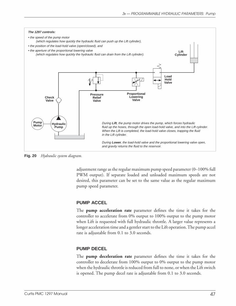
Curtis PMC 1297 Manual 47
adjustment range as the regular maximum pump speed parameter (0–100% fullPWM output). If separate loaded and unloaded maximum speeds are notdesired, this parameter can be set to the same value as the regular maximumpump speed parameter.
PUMP ACCEL
The pump acceleration rate parameter defines the time it takes for thecontroller to accelerate from 0% output to 100% output to the pump motorwhen Lift is requested with full hydraulic throttle. A larger value represents alonger acceleration time and a gentler start to the Lift operation. The pump accelrate is adjustable from 0.1 to 3.0 seconds.
PUMP DECEL
The pump deceleration rate parameter defines the time it takes for thecontroller to decelerate from 100% output to 0% output to the pump motorwhen the hydraulic throttle is reduced from full to none, or when the Lift switchis opened. The pump decel rate is adjustable from 0.1 to 3.0 seconds.
3B — PROGRAMMABLE HYDRAULIC PARAMETERS: Pump
Fig. 20 Hydraulic system diagram.
LoadHoldValve
LiftCylinder
ProportionalLowering
Valve
PressureReliefValve
PumpMotor Hydraulic
Pump
CheckValve
The 1297 controls:
• the speed of the pump motor(which regulates how quickly the hydraulic fluid can push up the Lift cylinder),
• the position of the load-hold valve (open/closed), and
• the aperture of the proportional lowering valve(which regulates how quickly the hydraulic fluid can drain from the Lift cylinder).
During Lift, the pump motor drives the pump, which forces hydraulicfluid up the hoses, through the open load-hold valve, and into the Lift cylinder.When the Lift is completed, the load-hold valve closes, trapping the fluidin the Lift cylinder.
During Lower, the load-hold valve and the proportional lowering valve open,and gravity returns the fluid to the reservoir.
Curtis PMC 1297 Manual 48
Lift operation can be prevented during overcurrent conditions or when the batterystate-of-charge is below 20%. These are safety measures to protect the operator andthe pump motor. In addition, both Lift and Lower can be prevented if more than25% throttle is requested at the time the interlock switch is closed.
PUMP LOCK C/L
The pump lockout current limit parameter allows Lift operation to beprohibited when the pump motor current exceeds the set threshold. Thisthreshold is adjustable from 25 amps to more than the controller’s full ratedpump current; the ceiling is 50 amps above the rated current. (The full ratedpump current depends on the controller model; see specifications in Table E-1.)
PUMP LOCK DLY
The pump lockout delay parameter allows a delay after the pump motorcurrent exceeds the pump lockout current limit before Lift operation is prohib-ited. The pump lockout delay is adjustable from 0.1 to 25.0 seconds.
PUMP BDI L/O
The pump BDI lockout feature prevents Lift operation when the battery state-of-charge is below 20%. This parameter can be programmed On or Off. Whenprogrammed On, if the battery S-O-C drops below 20% during a Lift opera-tion, the Lift in progress will be completed but further Lift requests will beignored as long as the battery S-O-C stays below 20%. If programmed Off, theLift will continue operating until the undervoltage cutoff point is reached.
PUMP BDI WRN
If the battery state-of-charge is less than 25%, the pump BDI lockout warningfeature beeps the horn twice each time Lift is requested, thus alerting theoperator to the low S-O-C condition. The warning parameter can be pro-grammed On or Off.
HYD INHIBIT
The hydraulic inhibit feature prevents Lift or Lower operation if the hydraulicthrottle request is >25% when the interlock switch is closed. The hydraulicinhibit parameter can be programmed On or Off. Sequencing delay (see page57) can be used to provide a brief delay before controller output is inhibited.
3B — PROGRAMMABLE HYDRAULIC PARAMETERS: Lift Lockout
Lift Lockout Parameters

Curtis PMC 1297 Manual 49
The 1297 controls the operation of the load-hold valve and the proportional loweringvalve, as shown in Figure 21. By so doing, it controls the hydraulic path for Lift andLower operations. Some hydraulic systems have a proportional lowering valve but noload-hold valve. Others have a simple open/closed lowering valve in place of aproportional valve. In these systems, variable lowering (i.e., lowering in proportionto the amount of throttle applied) is not possible. See box at the bottom of the nextpage for more information about this kind of system.
LV MAX CURR
The Lower speed is determined by the aperture of the lowering valve. The LVmaximum current parameter sets the maximum current the controller willprovide to the lowering valve. The LV maximum current is programmable from0.0 to 3.0 amps.
For proportional valves, the LV maximum current can be set to limit thevalve’s full aperture. Non-proportional valves always open completely; for thesevalves, the LV maximum current should be set to the valve’s full current rating.
LV MIN CURR
The LV minimum current parameter sets the minimum current through thelowering valve. Most proportional valves need a non-zero closed current in orderto start opening immediately when Lower is requested. The LV minimumcurrent is programmable from 0.0 to 1.0 amp. For non-proportional loweringvalves, the controller does not look at this parameter so its setting is irrelevant.
LV DITHER
The lowering valve dither feature provides a constantly changing current in thecoil to produce a rapid back-and-forth motion of the valve. This keeps propor-tional valves lubricated and allows low-friction, precise movement. The LVdither % parameter specifies the amount of dither as a percentage of the LVmaximum current, and is applied in a continuous 200 Hz cycle of none–add%–none–subtract%. The LV dither is programmable from 0 to 100%.
For non-proportional lowering valves, where the valve’s opening andclosing is spring-activated, dither is not applicable. If your application uses thistype of lowering valve, set the dither parameter to 0%.
LV ACCEL
The LV current acceleration rate parameter specifies how long it will take thelowering valve current to increase from 0% to 100%. The LV current accel rateis programmable from 0.0 to 3.0 seconds.
Valve Control Parameters
3B — PROGRAMMABLE HYDRAULIC PARAMETERS: Valve Control
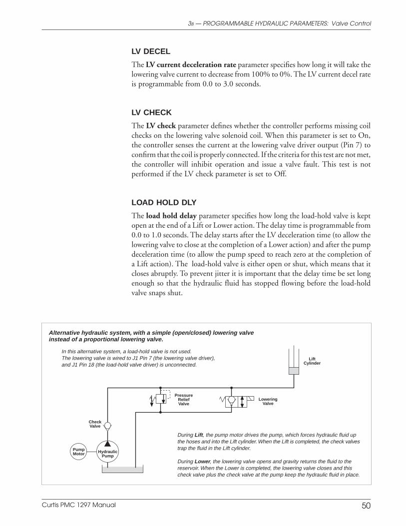
Curtis PMC 1297 Manual 50
3B — PROGRAMMABLE HYDRAULIC PARAMETERS: Valve Control
LiftCylinder
PumpMotor Hydraulic
Pump
CheckValve
Alternative hydraulic system, with a simple (open/closed) lowering valveinstead of a proportional lowering valve.
During Lift, the pump motor drives the pump, which forces hydraulic fluid upthe hoses and into the Lift cylinder. When the Lift is completed, the check valvestrap the fluid in the Lift cylinder.
During Lower, the lowering valve opens and gravity returns the fluid to thereservoir. When the Lower is completed, the lowering valve closes and thischeck valve plus the check valve at the pump keep the hydraulic fluid in place.
LoweringValve
PressureReliefValve
In this alternative system, a load-hold valve is not used.The lowering valve is wired to J1 Pin 7 (the lowering valve driver),and J1 Pin 18 (the load-hold valve driver) is unconnected.
LV DECEL
The LV current deceleration rate parameter specifies how long it will take thelowering valve current to decrease from 100% to 0%. The LV current decel rateis programmable from 0.0 to 3.0 seconds.
LV CHECK
The LV check parameter defines whether the controller performs missing coilchecks on the lowering valve solenoid coil. When this parameter is set to On,the controller senses the current at the lowering valve driver output (Pin 7) toconfirm that the coil is properly connected. If the criteria for this test are not met,the controller will inhibit operation and issue a valve fault. This test is notperformed if the LV check parameter is set to Off.
LOAD HOLD DLY
The load hold delay parameter specifies how long the load-hold valve is keptopen at the end of a Lift or Lower action. The delay time is programmable from0.0 to 1.0 seconds. The delay starts after the LV deceleration time (to allow thelowering valve to close at the completion of a Lower action) and after the pumpdeceleration time (to allow the pump speed to reach zero at the completion ofa Lift action). The load-hold valve is either open or shut, which means that itcloses abruptly. To prevent jitter it is important that the delay time be set longenough so that the hydraulic fluid has stopped flowing before the load-holdvalve snaps shut.
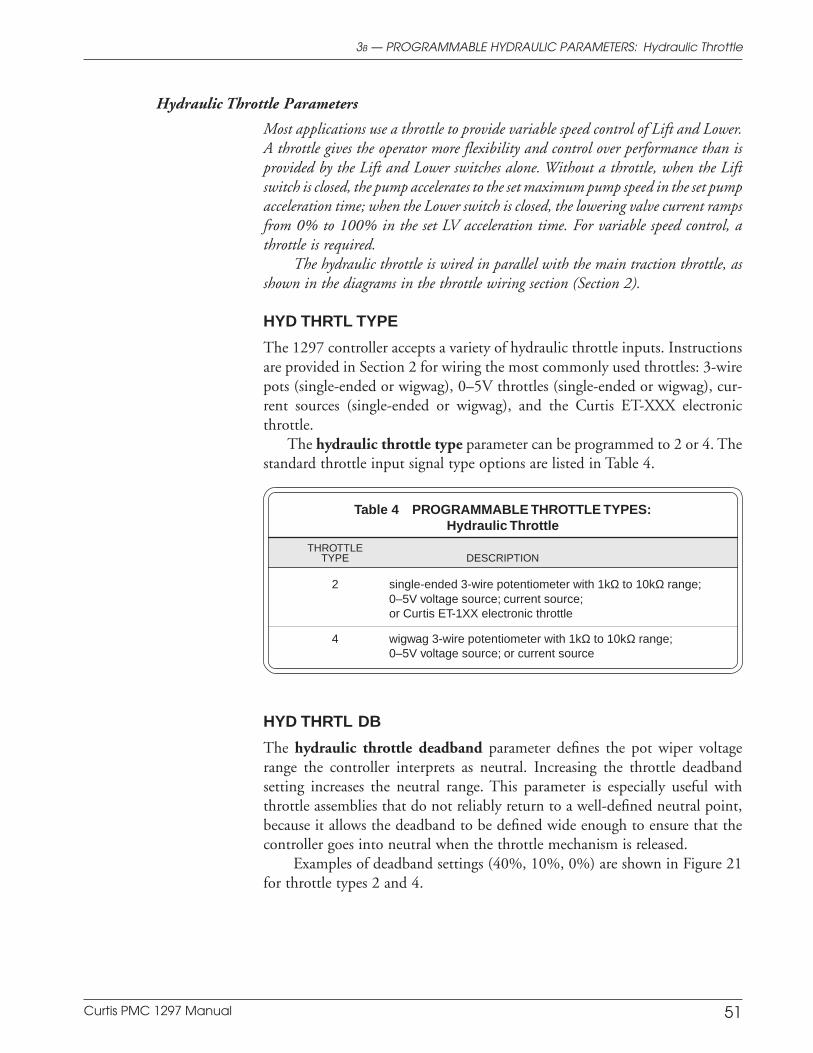
Curtis PMC 1297 Manual 51
Most applications use a throttle to provide variable speed control of Lift and Lower.A throttle gives the operator more flexibility and control over performance than isprovided by the Lift and Lower switches alone. Without a throttle, when the Liftswitch is closed, the pump accelerates to the set maximum pump speed in the set pumpacceleration time; when the Lower switch is closed, the lowering valve current rampsfrom 0% to 100% in the set LV acceleration time. For variable speed control, athrottle is required.
The hydraulic throttle is wired in parallel with the main traction throttle, asshown in the diagrams in the throttle wiring section (Section 2).
HYD THRTL TYPE
The 1297 controller accepts a variety of hydraulic throttle inputs. Instructionsare provided in Section 2 for wiring the most commonly used throttles: 3-wirepots (single-ended or wigwag), 0–5V throttles (single-ended or wigwag), cur-rent sources (single-ended or wigwag), and the Curtis ET-XXX electronicthrottle.
The hydraulic throttle type parameter can be programmed to 2 or 4. Thestandard throttle input signal type options are listed in Table 4.
Table 4 PROGRAMMABLE THROTTLE TYPES:Hydraulic Throttle
THROTTLETYPE DESCRIPTION
2 single-ended 3-wire potentiometer with 1kΩ to 10kΩ range;0–5V voltage source; current source;or Curtis ET-1XX electronic throttle
4 wigwag 3-wire potentiometer with 1kΩ to 10kΩ range;0–5V voltage source; or current source
HYD THRTL DB
The hydraulic throttle deadband parameter defines the pot wiper voltagerange the controller interprets as neutral. Increasing the throttle deadbandsetting increases the neutral range. This parameter is especially useful withthrottle assemblies that do not reliably return to a well-defined neutral point,because it allows the deadband to be defined wide enough to ensure that thecontroller goes into neutral when the throttle mechanism is released.
Examples of deadband settings (40%, 10%, 0%) are shown in Figure 21for throttle types 2 and 4.
Hydraulic Throttle Parameters
3B — PROGRAMMABLE HYDRAULIC PARAMETERS: Hydraulic Throttle
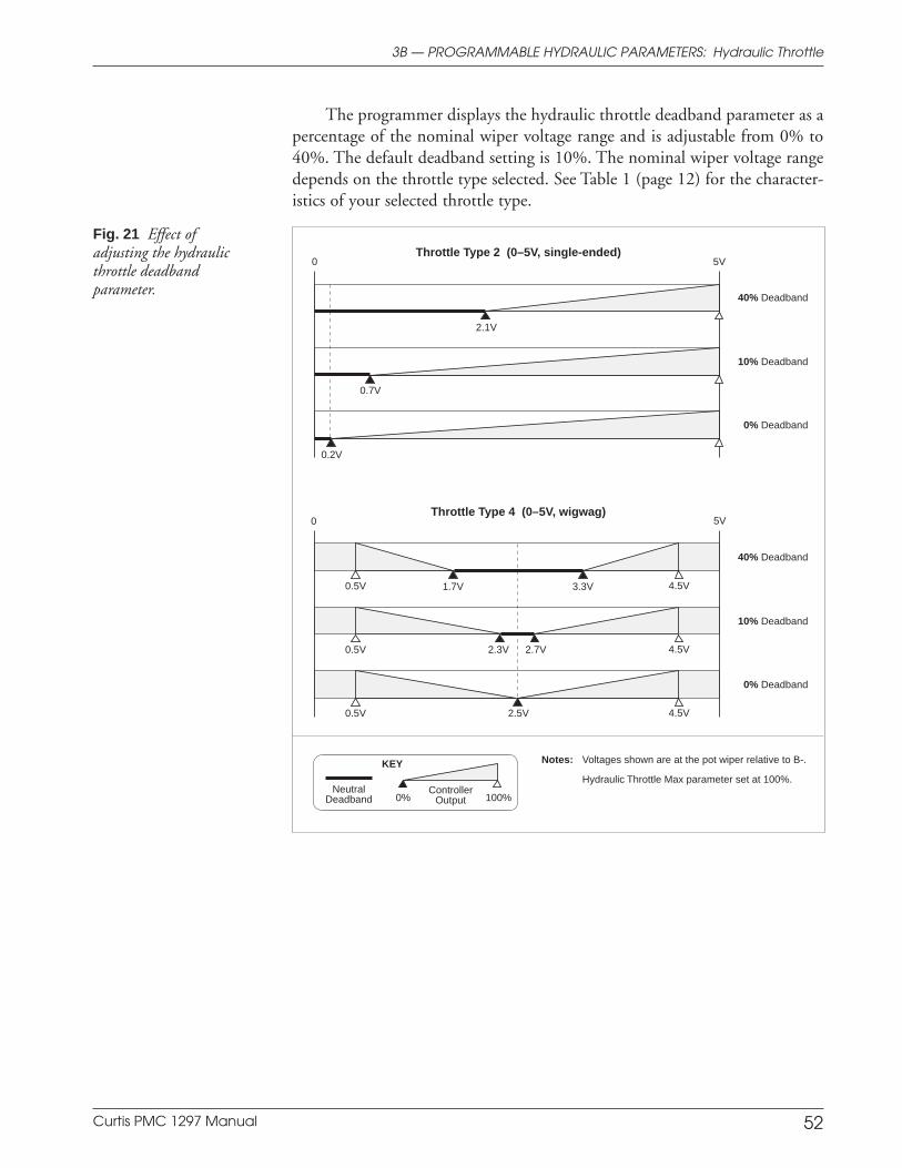
Curtis PMC 1297 Manual 52
The programmer displays the hydraulic throttle deadband parameter as apercentage of the nominal wiper voltage range and is adjustable from 0% to40%. The default deadband setting is 10%. The nominal wiper voltage rangedepends on the throttle type selected. See Table 1 (page 12) for the character-istics of your selected throttle type.
Fig. 21 Effect ofadjusting the hydraulicthrottle deadbandparameter.
3B — PROGRAMMABLE HYDRAULIC PARAMETERS: Hydraulic Throttle
Throttle Type 2 (0–5V, single-ended)
Throttle Type 4 (0–5V, wigwag)
Notes: Voltages shown are at the pot wiper relative to B-.
Hydraulic Throttle Max parameter set at 100%.
5V 0
40% Deadband
10% Deadband
0% Deadband
KEY
100%Neutral
DeadbandController
Output0%
5V 0
40% Deadband
10% Deadband
0% Deadband
0.2V
0.7V
2.1V
0.5V
2.7V
3.3V 4.5V
4.5V
4.5V2.5V
0.5V
0.5V
2.3V
1.7V
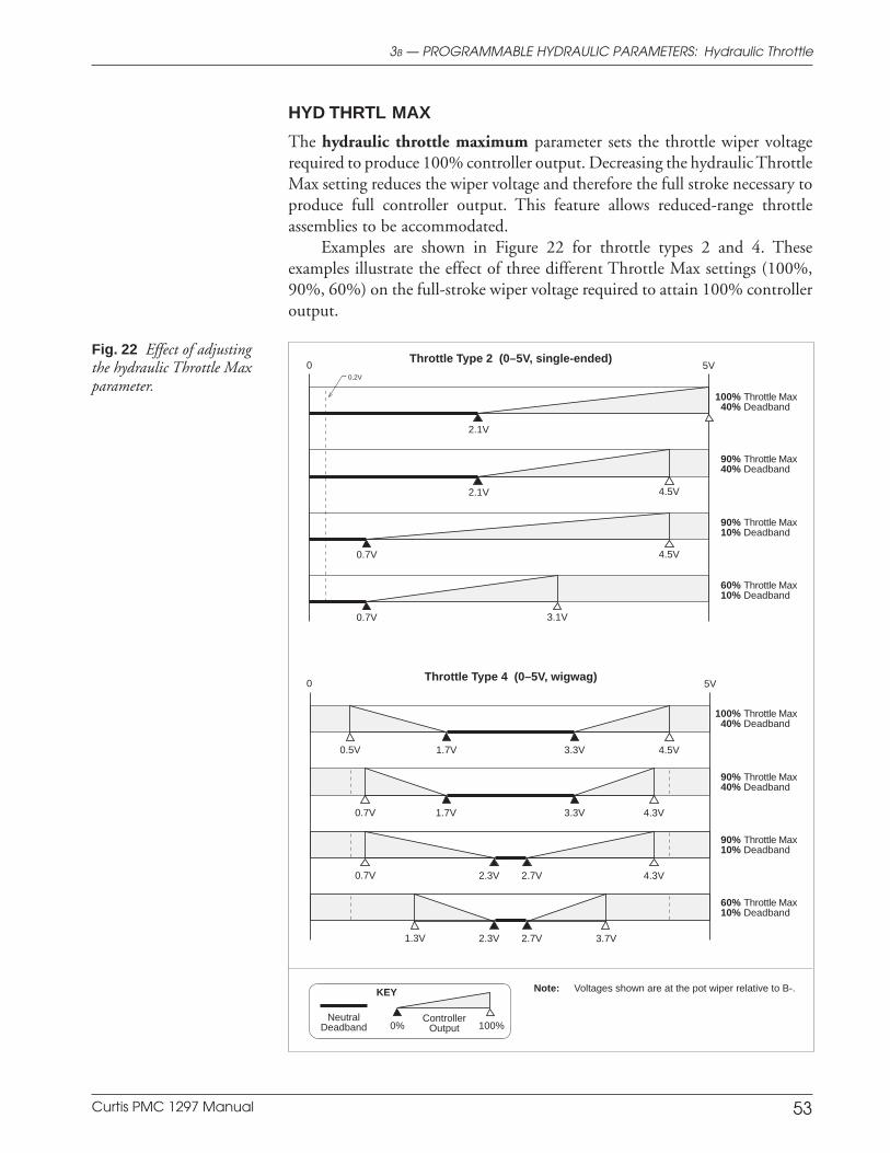
Curtis PMC 1297 Manual 53
HYD THRTL MAX
The hydraulic throttle maximum parameter sets the throttle wiper voltagerequired to produce 100% controller output. Decreasing the hydraulic ThrottleMax setting reduces the wiper voltage and therefore the full stroke necessary toproduce full controller output. This feature allows reduced-range throttleassemblies to be accommodated.
Examples are shown in Figure 22 for throttle types 2 and 4. Theseexamples illustrate the effect of three different Throttle Max settings (100%,90%, 60%) on the full-stroke wiper voltage required to attain 100% controlleroutput.
Fig. 22 Effect of adjustingthe hydraulic Throttle Maxparameter.
3B — PROGRAMMABLE HYDRAULIC PARAMETERS: Hydraulic Throttle
Throttle Type 2 (0–5V, single-ended)
Throttle Type 4 (0–5V, wigwag)
Note: Voltages shown are at the pot wiper relative to B-.KEY
100%Neutral
DeadbandController
Output0%
0 5V
100% Throttle Max40% Deadband
90% Throttle Max40% Deadband
90% Throttle Max10% Deadband
60% Throttle Max10% Deadband
0 5V
100% Throttle Max40% Deadband
90% Throttle Max40% Deadband
90% Throttle Max10% Deadband
60% Throttle Max10% Deadband
2.1V
0.7V 4.5V
0.7V 3.1V
2.1V 4.5V
0.2V
3.3V 4.5V0.5V 1.7V
3.3V 4.3V0.7V 1.7V
2.7V 4.3V0.7V 2.3V
2.7V 3.7V1.3V 2.3V
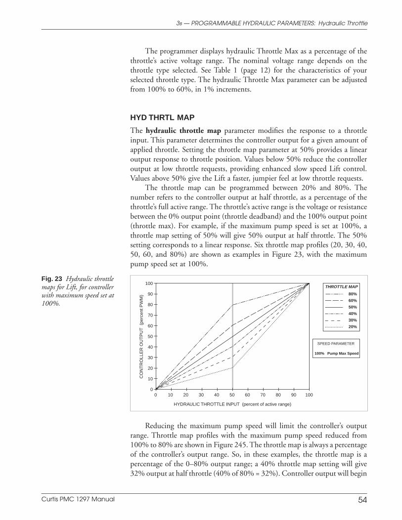
Curtis PMC 1297 Manual 54
The programmer displays hydraulic Throttle Max as a percentage of thethrottle’s active voltage range. The nominal voltage range depends on thethrottle type selected. See Table 1 (page 12) for the characteristics of yourselected throttle type. The hydraulic Throttle Max parameter can be adjustedfrom 100% to 60%, in 1% increments.
HYD THRTL MAP
The hydraulic throttle map parameter modifies the response to a throttleinput. This parameter determines the controller output for a given amount ofapplied throttle. Setting the throttle map parameter at 50% provides a linearoutput response to throttle position. Values below 50% reduce the controlleroutput at low throttle requests, providing enhanced slow speed Lift control.Values above 50% give the Lift a faster, jumpier feel at low throttle requests.
The throttle map can be programmed between 20% and 80%. Thenumber refers to the controller output at half throttle, as a percentage of thethrottle’s full active range. The throttle’s active range is the voltage or resistancebetween the 0% output point (throttle deadband) and the 100% output point(throttle max). For example, if the maximum pump speed is set at 100%, athrottle map setting of 50% will give 50% output at half throttle. The 50%setting corresponds to a linear response. Six throttle map profiles (20, 30, 40,50, 60, and 80%) are shown as examples in Figure 23, with the maximumpump speed set at 100%.
3B — PROGRAMMABLE HYDRAULIC PARAMETERS: Hydraulic Throttle
Fig. 23 Hydraulic throttlemaps for Lift, for controllerwith maximum speed set at100%.
HYDRAULIC THROTTLE INPUT (percent of active range)
80%
60%
50%
40%
30%
20%
THROTTLE MAP100
90
80
70
60
50
40
30
20
10
0100908070605040302010 0
SPEED PARAMETER
100% Pump Max Speed
CO
NT
RO
LLE
R O
UT
PU
T (
perc
ent P
WM
)
Reducing the maximum pump speed will limit the controller’s outputrange. Throttle map profiles with the maximum pump speed reduced from100% to 80% are shown in Figure 245. The throttle map is always a percentageof the controller’s output range. So, in these examples, the throttle map is apercentage of the 0–80% output range; a 40% throttle map setting will give32% output at half throttle (40% of 80% = 32%). Controller output will begin
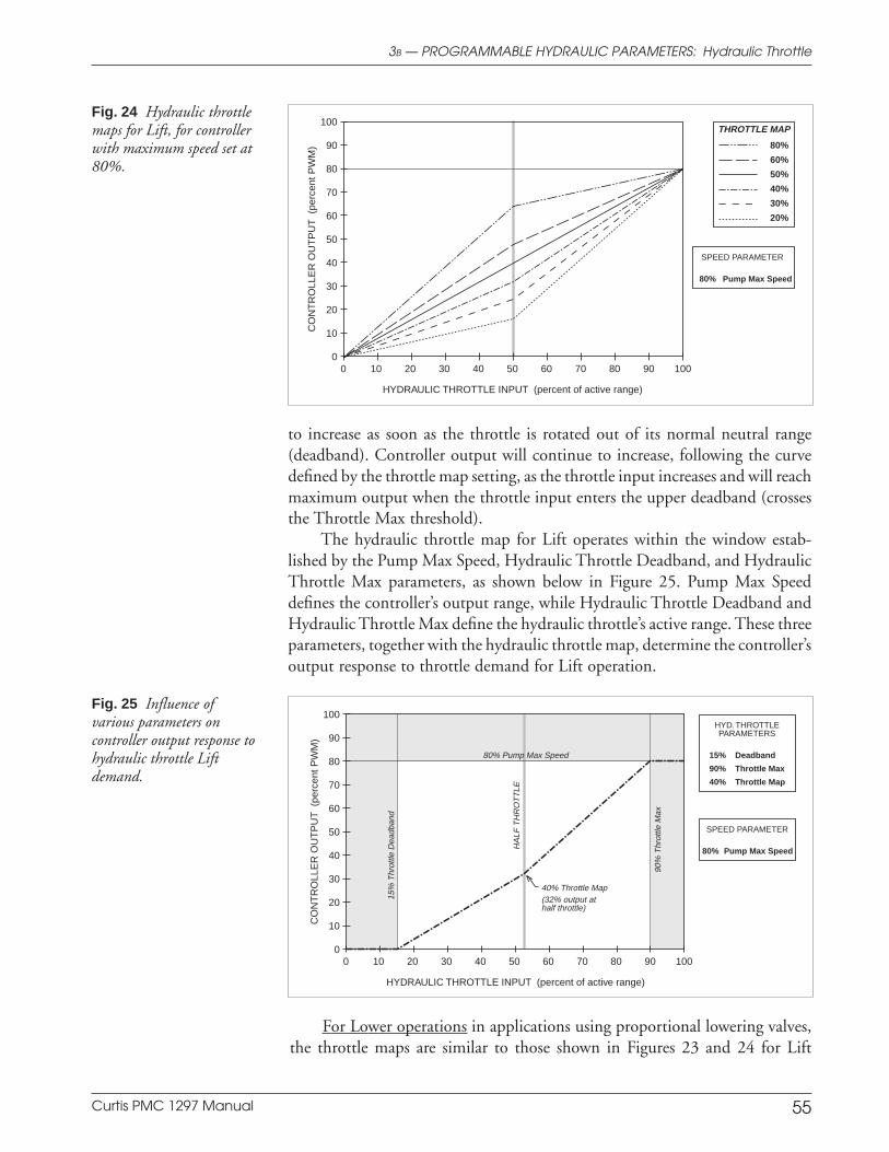
Curtis PMC 1297 Manual 55
to increase as soon as the throttle is rotated out of its normal neutral range(deadband). Controller output will continue to increase, following the curvedefined by the throttle map setting, as the throttle input increases and will reachmaximum output when the throttle input enters the upper deadband (crossesthe Throttle Max threshold).
The hydraulic throttle map for Lift operates within the window estab-lished by the Pump Max Speed, Hydraulic Throttle Deadband, and HydraulicThrottle Max parameters, as shown below in Figure 25. Pump Max Speeddefines the controller’s output range, while Hydraulic Throttle Deadband andHydraulic Throttle Max define the hydraulic throttle’s active range. These threeparameters, together with the hydraulic throttle map, determine the controller’soutput response to throttle demand for Lift operation.
3B — PROGRAMMABLE HYDRAULIC PARAMETERS: Hydraulic Throttle
Fig. 24 Hydraulic throttlemaps for Lift, for controllerwith maximum speed set at80%.
HYDRAULIC THROTTLE INPUT (percent of active range)
CO
NT
RO
LLE
R O
UT
PU
T (
perc
ent P
WM
) 80%
60%
50%
40%
30%
20%
THROTTLE MAP100
90
80
70
60
50
40
30
20
10
0100908070605040302010 0
SPEED PARAMETER
80% Pump Max Speed
Fig. 25 Influence ofvarious parameters oncontroller output response tohydraulic throttle Liftdemand.
HYDRAULIC THROTTLE INPUT (percent of active range)
CO
NT
RO
LLE
R O
UT
PU
T (
perc
ent P
WM
)
100908070605040302010 0
SPEED PARAMETER
80% Pump Max Speed
HYD. THROTTLEPARAMETERS
15% Deadband
90% Throttle Max
40% Throttle Map
80% Pump Max Speed
40% Throttle Map(32% output athalf throttle)
15%
Thr
ottle
Dea
dban
d
90%
Thr
ottle
Max
HA
LF T
HR
OT
TLE
100
90
80
70
60
50
40
30
20
10
0
For Lower operations in applications using proportional lowering valves,the throttle maps are similar to those shown in Figures 23 and 24 for Lift
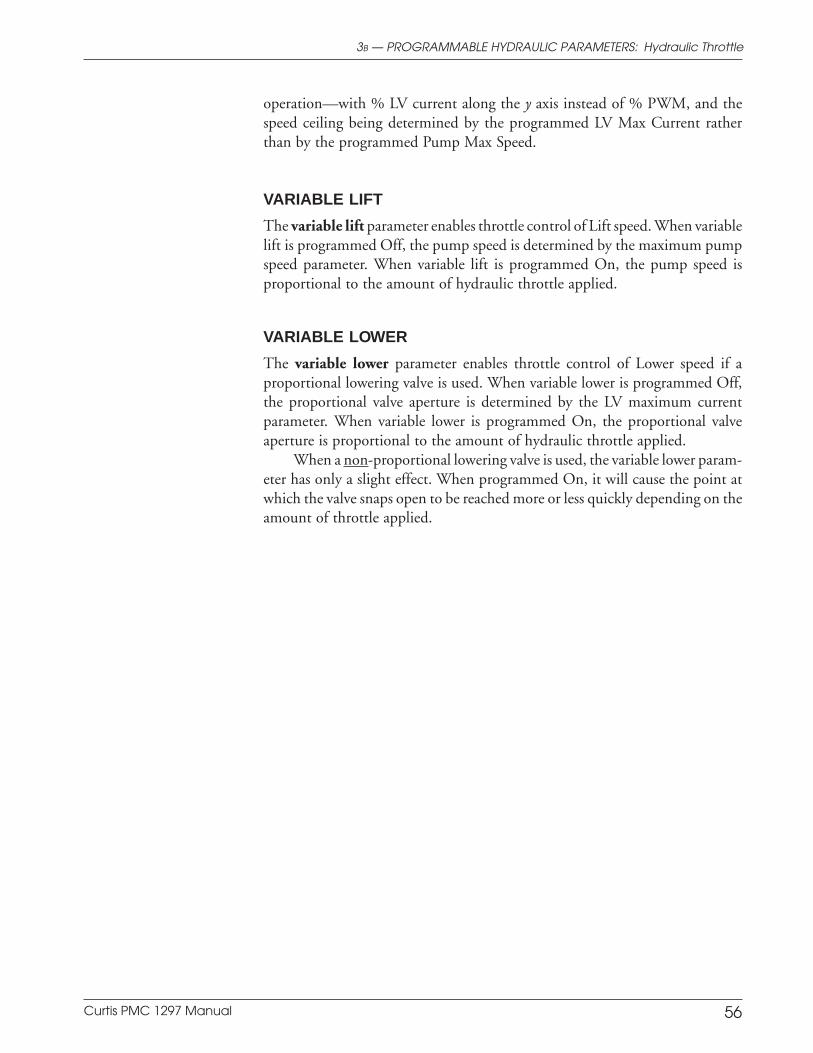
Curtis PMC 1297 Manual 56
operation—with % LV current along the y axis instead of % PWM, and thespeed ceiling being determined by the programmed LV Max Current ratherthan by the programmed Pump Max Speed.
VARIABLE LIFT
The variable lift parameter enables throttle control of Lift speed. When variablelift is programmed Off, the pump speed is determined by the maximum pumpspeed parameter. When variable lift is programmed On, the pump speed isproportional to the amount of hydraulic throttle applied.
VARIABLE LOWER
The variable lower parameter enables throttle control of Lower speed if aproportional lowering valve is used. When variable lower is programmed Off,the proportional valve aperture is determined by the LV maximum currentparameter. When variable lower is programmed On, the proportional valveaperture is proportional to the amount of hydraulic throttle applied.
When a non-proportional lowering valve is used, the variable lower param-eter has only a slight effect. When programmed On, it will cause the point atwhich the valve snaps open to be reached more or less quickly depending on theamount of throttle applied.
3B — PROGRAMMABLE HYDRAULIC PARAMETERS: Hydraulic Throttle
Curtis PMC 1297 Manual 57
C. SHARED PARAMETERS
In addition to the traction parameters and hydraulic parameters, there are a numberof parameters that affect both the traction and the hydraulic systems. These sharedparameters include the sequencing delay, various contactor parameters, the enable forthe multiplexer, and all the hourmeter and BDI parameters.
SEQUENCING DLY
The sequencing delay feature allows the interlock switch to be cycled within aset time (the sequencing delay), thus preventing inadvertent activation ofvarious lockout features. This feature is especially useful in applications wherethe interlock switch may bounce or be momentarily cycled during operation.The sequencing delay parameter can be set from 0.0 to 3.0 seconds, with zerocorresponding to no delay.
Sequencing delay affects two traction features (HPD and SRO) and onehydraulic feature (hydraulic inhibit).
MAIN CONT INT
The main contactor interlock parameter allows the OEM to define a dual switchrequirement to operate the vehicle. When this parameter is programmed On,both the KSI input (J1 Pin 1) and the interlock input (J1 Pin 2) must be pulledhigh (to B+) before the controller will engage the main contactor. The contactorwill open after the interlock switch is opened and the sequencing and contactordelays expire. When this parameter is set to Off, only KSI input is required forthe main contactor to be engaged.
MAIN OPEN DLY
The main contactor open delay parameter is applicable only if the maincontactor interlock parameter has been set to On. The delay can then be set toallow the contactor to remain closed for a period of time after the interlockswitch is opened. The delay is useful for preventing unnecessary cycling of thecontactor and for maintaining power to auxiliary functions that may be used fora short time after the interlock switch has opened.
The main contactor open delay is programmable from 0 to 40 seconds.
MAIN CONT DIAG
The main contactor diagnostics parameter, when set to On, performs ongoingchecks to ensure that the main contactor has closed properly each time it is
3C — PROGRAMMABLE SHARED PARAMETERS: Sequencing Delay & Contactor
Contactor Parameters
Sequencing D elay Parameter
Curtis PMC 1297 Manual 58
commanded to so, and that it has not welded closed. These checks are notperformed if the main contactor diagnostics parameter is set to Off. The maincontactor driver, however, is always protected from overcurrents, short circuits,and overheating.
MUX ENABLE
The multiplexer enable parameter, when programmed On, enables the J2connector—and thus the multiplexer—as shown in Figure 4, page 10. Whenthe multiplexer parameter is programmed Off, the J2 connector is inactive.
3C — PROGRAMMABLE SHARED PARAMETERS: Multiplexer
Multiplexer Parameter
Curtis PMC 1297 Manual 59
3C — PROGRAMMABLE SHARED PARAMETERS: Hourmeters
Three hourmeters are built into the 1297 controller, each with non-volatile memory:• a total hourmeter, that measures the total operating time (KSI on-time),• a traction hourmeter, that measures the traction motor on-time, and• a pump hourmeter, that measures the pump motor on-time.
Each of these three hourmeters has a corresponding service timer and disable timer.Hourmeter information is viewable via the Spyglass display.
For each hourmeter, the service timer is used to set the time before scheduledmaintenance is due. When the set service time expires, the disable timer starts andthe service timer resets. If the disable time expires before the scheduled maintenanceis performed, the controller defaults to the set disable speed.
The 1297 controller is shipped from the factory with each of its three hourmeterspreset to 0. If the controller is being installed in a new vehicle, these presets do notneed to be adjusted. If the controller is being installed in a “used” vehicle, however,it may be desirable to transfer the existing hourmeter values to the new controller. Todo this, the existing decimal hourmeter values must be converted to 8-bit binaryvalues, as follows.
ADJ HOURS HIGH
The adjust hours high parameter is used to adjust the high byte of thehourmeter preset; it can be set from 0 to 151. To calculate this value, divide thedesired hours by 6,553.6 and enter the integer portion of the result for theAdjust Hours High value.
ADJ HOURS MID
The adjust hours middle parameter is used to adjust the middle byte of thehourmeter preset; it can be set from 0 to 255. To calculate this value, multiplythe Hours High value by 6,553.6, subtract the result from the desired hours,divide by 25.6, and enter this integer value for the Adjust Hours Middle value.
ADJ HOURS LOW
The adjust hours low parameter is used to adjust the low byte of the hourmeterpreset; it can be set from 0 to 255. To calculate this value, subtract the HoursMiddle integer value from the total Hours Middle value (in other words, takethe remainder), multiply by 256, and enter this integer value for the AdjustHours Low value.
Hourmeter Parameters
Hourmeter “Preset” Settings
Curtis PMC 1297 Manual 60
3C — PROGRAMMABLE SHARED PARAMETERS: Hourmeters
SET TOTL HRS
The set total hours parameter is used to apply the preset high, middle, and lowbyte values to the total (i.e., KSI on-time) hourmeter. First, adjust the byte valuesas desired for the total hourmeter. Then, program the Apply Total Hoursparameter On, which automatically loads the preset values. Once they have beenloaded, the apply hours parameter should be programmed Off.
SET TRAC HRS
The set traction hours parameter is used to apply preset high, middle, and lowbyte values to the traction hourmeter. First, adjust the byte values as desired forthe traction hourmeter. Then, program the Apply Traction Hours parameterOn, which automatically loads the preset values. Once they have been loaded,the apply hours parameter should be programmed Off.
SET PUMP HRS
The set pump hours parameter is used to apply preset high, middle, and lowbyte values to the pump hourmeter. First, adjust the byte values as desired forthe pump hourmeter. Then, program the Apply Pump Hours parameter On,which automatically loads the preset values. Once they have been loaded, theapply hours parameter should be programmed Off.
SRVC TOTL HRS
The total service hours parameter is used to set the timer for the next scheduledoverall maintenance. The total service timer can be adjusted between 0.0 and50.0, in 0.1 increments, with 25.0 being equivalent to 2,500 hours (25.0 × 100).
SRVC TRAC HRS
The traction service hours parameter is used to set the timer for the nextscheduled traction motor maintenance. The traction service timer can beadjusted between 0.0 and 50.0, in 0.1 increments, with 25.0 being equivalentto 2,500 hours (25.0 × 100).
SRVC PUMP HRS
The pump service hours parameter is used to set the timer for the nextscheduled pump motor maintenance. The pump service timer can be adjustedbetween 0.0 and 50.0, in 0.1 increments, with 25.0 being equivalent to 2,500hours (25.0 × 100).
Hourmeter Service Timer Setting

Curtis PMC 1297 Manual 61
3C — PROGRAMMABLE SHARED PARAMETERS: Hourmeters
DIS TOTL HRS
The total disable hours parameter is used to set the total disable timer; it canbe adjusted between 0 and 250 hours, in 1 hour increments. If the total disabletimer expires, the traction fault speed and pump fault speed both go into effect.
DIS TRAC HRS
The traction disable hours parameter is used to set the traction disable timer;it can be adjusted between 0 and 250 hours, in 1 hour increments. If the tractiondisable timer expires, the traction fault speed goes into effect.
DIS PUMP HRS
The pump disable hours parameter is used to set the pump disable timer; it canbe adjusted between 0 and 250 hours, in 1 hour increments. If the pump disabletimer expires, the pump fault speed goes into effect.
TRAC FAULT SPD
The traction fault speed parameter sets the maximum drive speed in the eventthe traction disable timer expires or the total disable timer expires; it can beadjusted between 0–100% of Max Speed, and applies to both M1 Max Speedand M2 Max Speed.
PUMP FAULT SPD
The pump fault speed parameter sets the maximum pump motor speed in theevent the pump disable timer expires or the total disable timer expires; it can beadjusted between 0–100% of Pump Max Speed.
Hourmeter Disable Timer Setting
Curtis PMC 1297 Manual 62
SERVICE TOTL
When the total service timer expires, the controller automatically sets theservice total parameter On. The user must then program the service totalparameter Off to indicate the appropriate service has been performed.
SERVICE TRAC
When the traction service timer expires, the controller automatically sets theservice traction parameter On. The user must then program the service tractionparameter Off to indicate the appropriate service has been performed.
SERVICE PUMP
When the pump service timer expires, the controller automatically sets theservice pump parameter On. The user must then program the service pumpparameter Off to indicate the appropriate service has been performed.
3C — PROGRAMMABLE SHARED PARAMETERS: Hourmeters
Hourmeter Reset Service Times
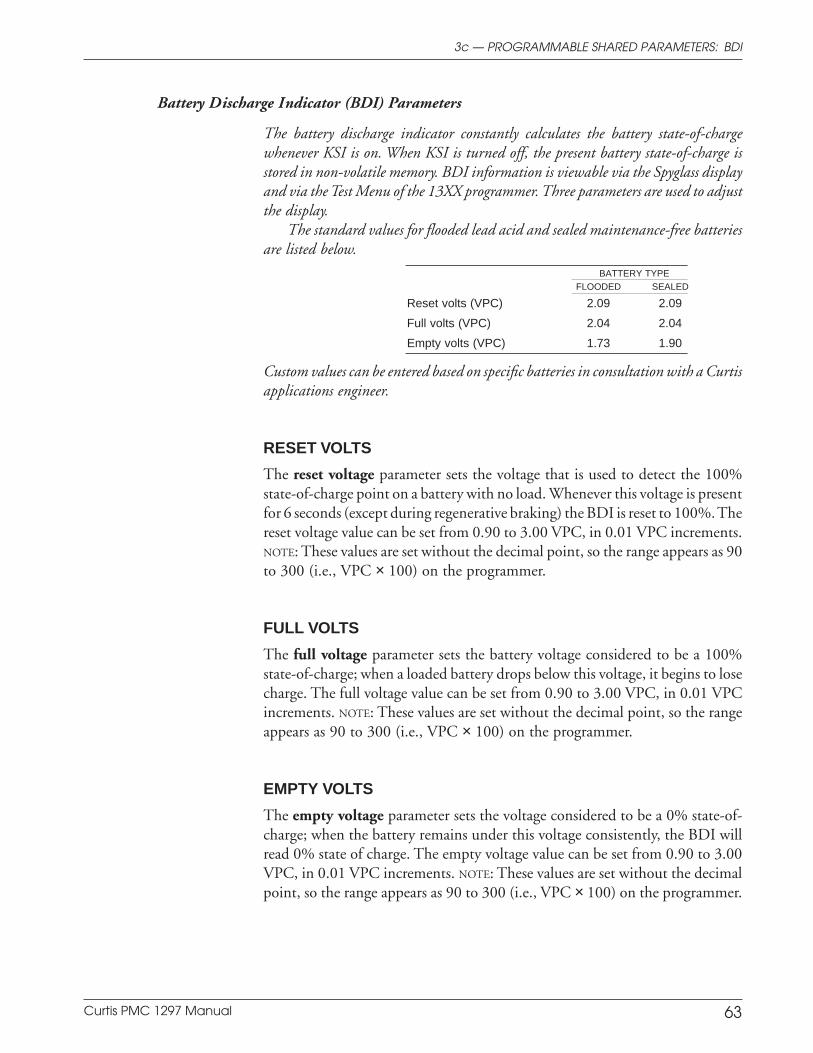
Curtis PMC 1297 Manual 63
3c — PROGRAMMABLE SHARED PARAMETERS: BDI
Battery Discharge Indicator (BDI) Parameters
The battery discharge indicator constantly calculates the battery state-of-chargewhenever KSI is on. When KSI is turned off, the present battery state-of-charge isstored in non-volatile memory. BDI information is viewable via the Spyglass displayand via the Test Menu of the 13XX programmer. Three parameters are used to adjustthe display.
The standard values for flooded lead acid and sealed maintenance-free batteriesare listed below.
BATTERY TYPEFLOODED SEALED
Reset volts (VPC) 2.09 2.09
Full volts (VPC) 2.04 2.04
Empty volts (VPC) 1.73 1.90
Custom values can be entered based on specific batteries in consultation with a Curtisapplications engineer.
RESET VOLTS
The reset voltage parameter sets the voltage that is used to detect the 100%state-of-charge point on a battery with no load. Whenever this voltage is presentfor 6 seconds (except during regenerative braking) the BDI is reset to 100%. Thereset voltage value can be set from 0.90 to 3.00 VPC, in 0.01 VPC increments.NOTE: These values are set without the decimal point, so the range appears as 90to 300 (i.e., VPC × 100) on the programmer.
FULL VOLTS
The full voltage parameter sets the battery voltage considered to be a 100%state-of-charge; when a loaded battery drops below this voltage, it begins to losecharge. The full voltage value can be set from 0.90 to 3.00 VPC, in 0.01 VPCincrements. NOTE: These values are set without the decimal point, so the rangeappears as 90 to 300 (i.e., VPC × 100) on the programmer.
EMPTY VOLTS
The empty voltage parameter sets the voltage considered to be a 0% state-of-charge; when the battery remains under this voltage consistently, the BDI willread 0% state of charge. The empty voltage value can be set from 0.90 to 3.00VPC, in 0.01 VPC increments. NOTE: These values are set without the decimalpoint, so the range appears as 90 to 300 (i.e., VPC × 100) on the programmer.
Curtis PMC 1297 Manual 64
INSTALLATION CHECKOUT
Carefully complete the following checkout procedure before operating thevehicle. If you find a problem during the checkout, refer to the diagnostics andtroubleshooting section (Section 7) for further information.
The installation checkout can be conducted with or without a 13XXprogrammer. The checkout procedure is easier with a programmer. Otherwise,observe the Status LED (located in the controller’s label area) or the optionalSpyglass display for diagnostic codes. The codes are listed in Section 7.
Before starting the procedure, check that the hydraulic hoses are secure,and the system primed with oil.
Put the vehicle up on blocks to get the drive wheels up offthe ground before beginning these tests.
Do not stand, or allow anyone else to stand, directly infront of or beside the vehicle during the checkout.
Make sure the keyswitch is off, the throttles are in neutral,and all the switches are open.
Wear safety glasses and use well-insulated tools.
1. If a programmer is available, connect it to the 4-pin connector (J3).
2. Turn the keyswitch on. The programmer should power up with aninitial display, and the controller’s Status LED should begin steadilyblinking a single flash. If neither happens, check for continuity in thekeyswitch circuit and controller ground.
3. If you are using a programmer, put it into the diagnostic mode. Thedisplay should indicate “No Known Faults.” Close the interlock switch(if one is used in your application). The Status LED should continueblinking a single flash and the programmer should continue to indicateno faults.
If there is a problem, the LED will flash a diagnostic code and theprogrammer will display a diagnostic message. If you are conducting thecheckout without a programmer, look up the LED diagnostic code inSection 7 (Diagnostics and Troubleshooting).
When the problem has been corrected, it may be necessary tocycle the keyswitch in order to clear the fault.
4 — INSTALLATION CHECKOUT
4
C A U T I O N
Curtis PMC 1297 Manual 65
4. First, check out the traction system. With the interlock switch closed, selecta direction and apply throttle. The motor should begin to turn in theselected direction. If it does not, first verify the wiring to the forward andreverse switches. If the wiring is correct, turn off the controller, discon-nect the battery, and exchange the motor’s field connections (the F1 andF2 cables) on the controller. The motor should now turn in the properdirection. The motor should turn proportionately faster with increasingthrottle. If not, refer to Section 7. CAUTION: The polarity of the F1 andF2 connections will affect the operation of emergency reverse. Theforward and reverse switches and the field connections must be configuredso that the vehicle drives away from the operator when the emergencyreverse button is pressed.
5. If you are using a programmer, put it into the test mode. Observe thestatus of the forward, reverse, and mode switches, and—if your applica-tion has emergency reverse—the emergency reverse switch. Cycle eachswitch in turn, observing the programmer. The programmer shoulddisplay the correct status for each switch.
If your application has a multiplexer, cycle these switches on themultiplexer also.
6. Take the vehicle down off the blocks and drive it in a clear area. It shouldhave smooth acceleration and good top speed. If not, see Section 5:Vehicle Performance Adjustment.
7. Test the braking of the vehicle.
8. Verify that all options, such as high pedal disable (HPD), static returnto off (SRO), and anti-tiedown are as desired.
9. On walkies, verify that emergency reverse is working correctly. If youhave the optional emergency reverse check wiring, verify the checkingcircuit by momentarily disconnecting one of the emergency reversewires. The vehicle should coast to a stop and a fault should be indicated.
10. Next, check out the hydraulic system. If you are using a programmer, putit into the test mode. Observe the status of the Lift and Lower switches.Cycle each switch in turn, observing the programmer. The programmershould display the correct status for each switch.
If your application has a multiplexer, cycle the Lift and Lowerswitches on the multiplexer also.
11. Drive the vehicle to a location that will provide enough room for thehydraulic functions to be tested; if indoors, be sure the ceiling height isadequate.
4 — INSTALLATION CHECKOUT

Curtis PMC 1297 Manual 66
12. Using the hydraulic throttle, operate the Lift and Lower. They shouldaccelerate and decelerate smoothly.
13. Verify that the hydraulic inhibit feature performs as desired.
14. If you used a programmer, disconnect it when you have completed thecheckout procedure.
BENCH TESTING WITH A 13XX PROGRAMMER
With the simple bench test setup shown in Figure 26, the controller parameterscan be verified or adjusted without the controller being wired into a vehicle. Thewiring can be expanded to conduct a complete functional test on the bench; ifyou want to do this, contact Curtis for further information.
The complete in-vehicle installation checkout, as described in Steps 1–14,should still be conducted before the vehicle is operated.
Fig. 26 Bench test setupfor verifying and adjustingthe controller’s parameters.
KEYSWITCH
24 VPOWERSUPPLY
1307PROGRAMMER
1297CONTROLLER
J3J1 J2
TRACTIONM-
B-
B+
PUMP M-
F2
F1
J1 Pin 1
C U R T I S P M C
+ + + + + + + + + + + + + + + + + + + ++++
SCROLLDISPLAY
CHANGEVALUE
PROGRAM DIAGNOSTICS
MORE INFO
TEST
+++
4 — INSTALLATION CHECKOUT
Curtis PMC 1297 Manual 67
Preliminary on Verso page is set with right edge at 7 and 7/8,
and the top (as on the Recto page) at 1/4.
VEHICLE PERFORMANCE ADJUSTMENT
The 1297 controller is a very powerful vehicle control system. Its wide varietyof adjustable parameters allow many aspects of vehicle performance to beoptimized. This section provides explanations of what the major tuning param-eters do and instructions on how to use these parameters to optimize theperformance of your vehicle. Traction system tuning is described first, followedby hydraulic system tuning.
TRACTION TUNING: MAJOR
The tuning procedures should be conducted in the sequence given, becausesuccessive steps build upon the ones before. It is important that the effect ofthese programmable parameters be understood in order to take full advantageof the 1297 controller’s powerful features. Please refer to the descriptions of theapplicable parameters in Section 3A if there is any question about what any ofthem do.
Once a vehicle/motor/controller combination has been tuned, the pa-rameter values can be made standard for that system or vehicle model. Anychanges in the motor, the vehicle drive system, or the controller will requirethat the system be tuned again to provide optimum performance.
The 1297’s MultiMode™ feature allows the vehicle to be configured toprovide two distinct operating modes. Typically, Mode 1 is optimized forprecision maneuvering and Mode 2 for faster outdoor travel. If your vehicle isintended to operate in two modes, some of the tuning procedures must beperformed twice—once for each mode.
Four major performance characteristics of the traction system are usuallytuned on a new vehicle:
➀ Tuning the throttle’s active range
➁ Tuning the controller to the motor
➂ Setting the vehicle’s unloaded top speed
Equalization of loaded and unloaded vehicle speed.
These four characteristics should be tuned in the order listed.
➀ Tuning the Throttle’s Active Range
Before attempting to optimize any specific vehicle performance characteristics,it is important to ensure that the controller output is operating over its fullrange. To do this, the throttle should be tuned using a 13XX programmer. Theprocedures that follow will establish Throttle Deadband and Throttle Maxparameter values that correspond to the absolute full range of your particularthrottle mechanism. It is advisable to allow some buffer around the absolute full
55 — VEHICLE PERFORMANCE ADJUSTMENT
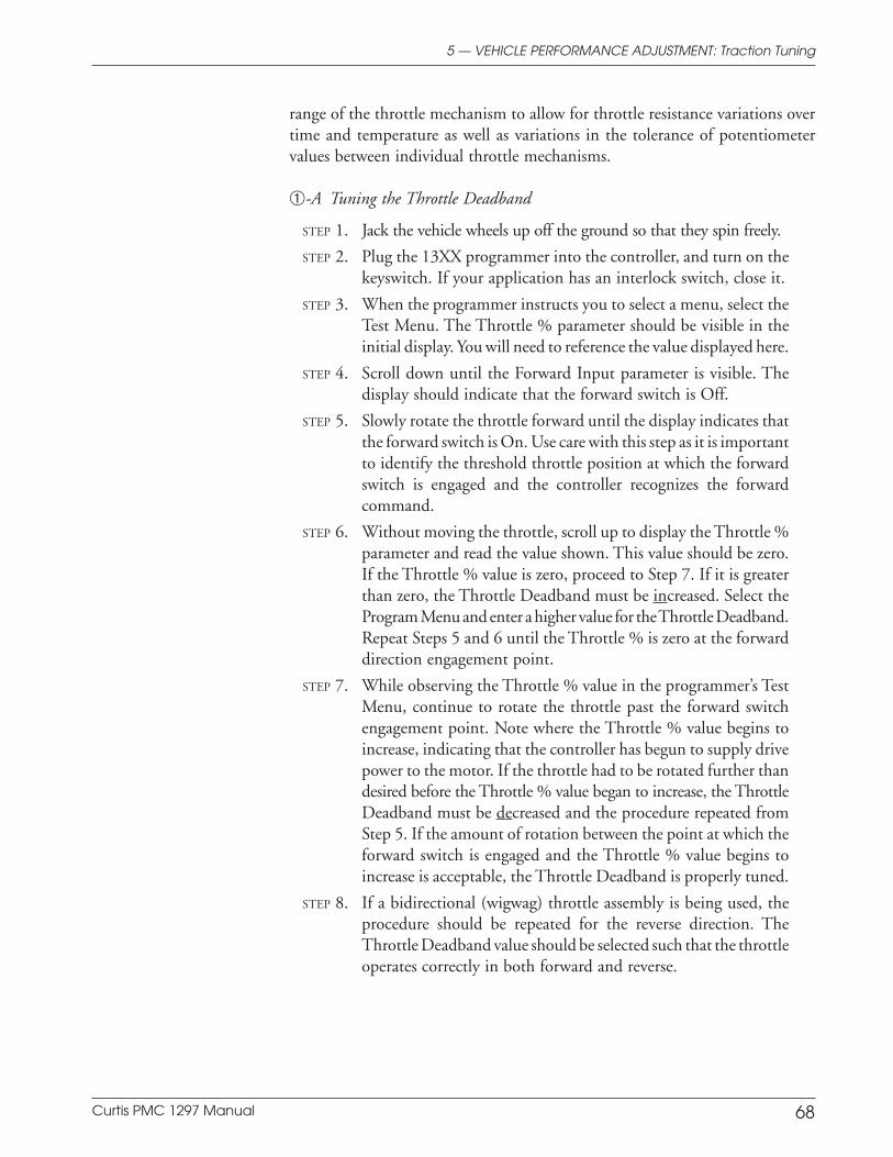
Curtis PMC 1297 Manual 68
Preliminary on Verso page is set with right edge at 7 and 7/8,
and the top (as on the Recto page) at 1/4.
5 — VEHICLE PERFORMANCE ADJUSTMENT: Traction Tuning
range of the throttle mechanism to allow for throttle resistance variations overtime and temperature as well as variations in the tolerance of potentiometervalues between individual throttle mechanisms.
➀-A Tuning the Throttle Deadband
STEP 1. Jack the vehicle wheels up off the ground so that they spin freely.
STEP 2. Plug the 13XX programmer into the controller, and turn on thekeyswitch. If your application has an interlock switch, close it.
STEP 3. When the programmer instructs you to select a menu, select theTest Menu. The Throttle % parameter should be visible in theinitial display. You will need to reference the value displayed here.
STEP 4. Scroll down until the Forward Input parameter is visible. Thedisplay should indicate that the forward switch is Off.
STEP 5. Slowly rotate the throttle forward until the display indicates thatthe forward switch is On. Use care with this step as it is importantto identify the threshold throttle position at which the forwardswitch is engaged and the controller recognizes the forwardcommand.
STEP 6. Without moving the throttle, scroll up to display the Throttle %parameter and read the value shown. This value should be zero.If the Throttle % value is zero, proceed to Step 7. If it is greaterthan zero, the Throttle Deadband must be increased. Select theProgram Menu and enter a higher value for the Throttle Deadband.Repeat Steps 5 and 6 until the Throttle % is zero at the forwarddirection engagement point.
STEP 7. While observing the Throttle % value in the programmer’s TestMenu, continue to rotate the throttle past the forward switchengagement point. Note where the Throttle % value begins toincrease, indicating that the controller has begun to supply drivepower to the motor. If the throttle had to be rotated further thandesired before the Throttle % value began to increase, the ThrottleDeadband must be decreased and the procedure repeated fromStep 5. If the amount of rotation between the point at which theforward switch is engaged and the Throttle % value begins toincrease is acceptable, the Throttle Deadband is properly tuned.
STEP 8. If a bidirectional (wigwag) throttle assembly is being used, theprocedure should be repeated for the reverse direction. TheThrottle Deadband value should be selected such that the throttleoperates correctly in both forward and reverse.
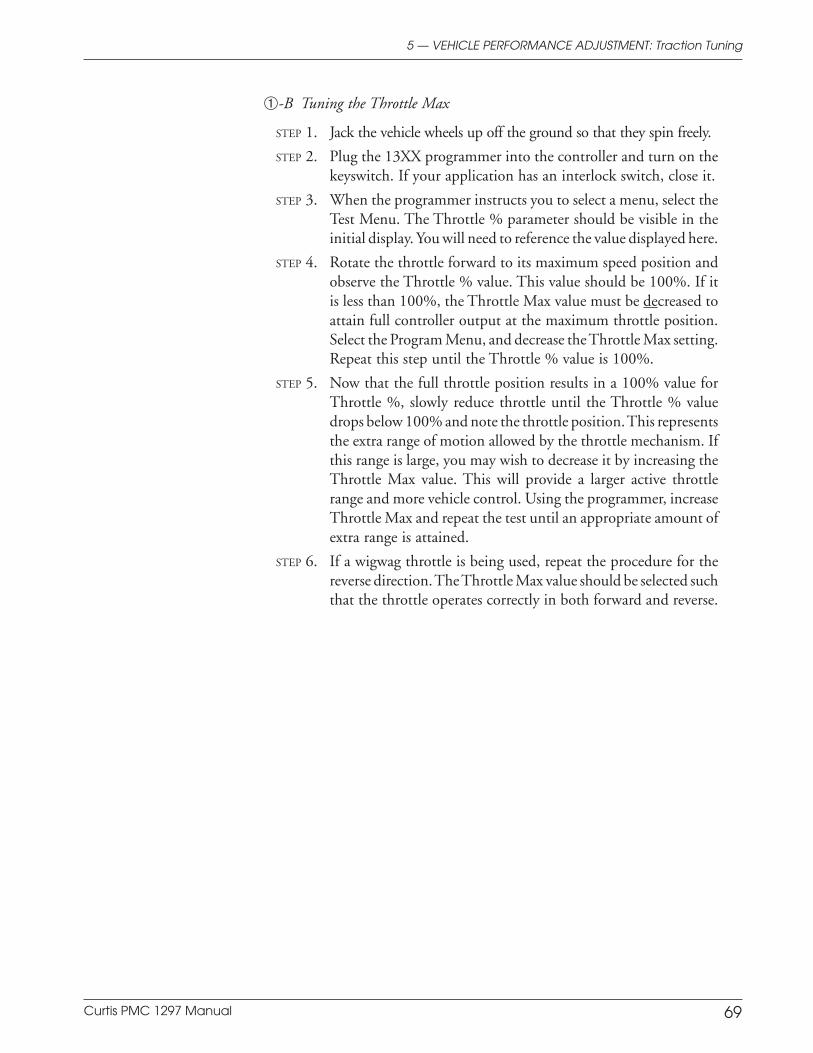
Curtis PMC 1297 Manual 69
Preliminary on Verso page is set with right edge at 7 and 7/8,
and the top (as on the Recto page) at 1/4.
➀-B Tuning the Throttle Max
STEP 1. Jack the vehicle wheels up off the ground so that they spin freely.
STEP 2. Plug the 13XX programmer into the controller and turn on thekeyswitch. If your application has an interlock switch, close it.
STEP 3. When the programmer instructs you to select a menu, select theTest Menu. The Throttle % parameter should be visible in theinitial display. You will need to reference the value displayed here.
STEP 4. Rotate the throttle forward to its maximum speed position andobserve the Throttle % value. This value should be 100%. If itis less than 100%, the Throttle Max value must be decreased toattain full controller output at the maximum throttle position.Select the Program Menu, and decrease the Throttle Max setting.Repeat this step until the Throttle % value is 100%.
STEP 5. Now that the full throttle position results in a 100% value forThrottle %, slowly reduce throttle until the Throttle % valuedrops below 100% and note the throttle position. This representsthe extra range of motion allowed by the throttle mechanism. Ifthis range is large, you may wish to decrease it by increasing theThrottle Max value. This will provide a larger active throttlerange and more vehicle control. Using the programmer, increaseThrottle Max and repeat the test until an appropriate amount ofextra range is attained.
STEP 6. If a wigwag throttle is being used, repeat the procedure for thereverse direction. The Throttle Max value should be selected suchthat the throttle operates correctly in both forward and reverse.
5 — VEHICLE PERFORMANCE ADJUSTMENT: Traction Tuning
Curtis PMC 1297 Manual 70
Preliminary on Verso page is set with right edge at 7 and 7/8,
and the top (as on the Recto page) at 1/4.
➁ Tuning the Controller to the Motor
The 1297 controller has the flexibility to be tuned to nearly any separatelyexcited motor from any manufacturer. Parameters in the 13XX programmer’sProgram Menu allow full control of the motor’s maximum armature currentduring driving and braking and full control of the motor’s maximum andminimum field current as well as the field current relationship to the armaturecurrent. This flexibility allows motor performance to be maximized whileprotecting it from operating outside its safe commutation region.
In order to properly tune the controller, the following information shouldbe obtained from the motor manufacturer:
– peak motor armature current rating
– maximum motor field current rating
– minimum motor field current rating
– motor field resistance, hot and cold.
The performance of a separately excited motor depends on temperature. This isdue to the change in field winding resistance as the motor heats up through use.When the field winding temperature increases, so does its resistance; therefore,the maximum current that can be forced through the winding is reduced.Reductions in the field current over the motor’s typical operating temperaturerange can be 10% to 50%. Since the maximum available field current deter-mines the maximum torque that can be produced by the motor, the vehicle’sperformance under load and up inclines will change as the motor heats up. Thechange in performance can be limited by tuning the motor when it is hot ratherthan cold. Therefore, it is recommended that the following procedure beperformed with a hot motor.
STEP 1. Using the programmer’s Program Menu, set the Drive CurrentLimit parameter in each mode to the smaller of: (a) the motor’speak armature current rating, or (b) the controller’s full rateddrive current. This setting can be adjusted later to establish thedesired vehicle driving feel in each mode.
STEP 2. Set the Braking Current Limit parameter in each mode to thesmaller of: (a) the motor’s peak armature current rating, or (b) thecontroller’s full rated braking current. This setting can be adjustedlater to establish the desired vehicle braking feel in each mode.
STEP 3. To set the Field Max parameter, first decide whether you want tomaintain consistent vehicle operation throughout the motor’stemperature range. If you do, proceed to Step 4. If, however,maintaining operational consistency across motor temperature isnot a concern—but achieving maximum torque is—proceed toStep 5.
5 — VEHICLE PERFORMANCE ADJUSTMENT: Traction Tuning
Curtis PMC 1297 Manual 71
Preliminary on Verso page is set with right edge at 7 and 7/8,
and the top (as on the Recto page) at 1/4.
STEP 4. For the most consistent operation across temperature, set theField Max to the maximum field current available at low batteryvoltage and with a hot motor. To determine this value, divide thelow battery voltage (typically 70% of nominal) by the hightemperature field winding resistance specification provided bythe manufacturer. Set the Field Max to this value. This settingwill provide good consistency between motor performance inboth hot and cold states.
STEP 5. For the maximum torque regardless of temperature, set the FieldMax to the motor’s rated absolute maximum field current. Todetermine the absolute maximum field current, divide the nomi-nal battery voltage by the low temperature field winding resis-tance specification provided by the manufacturer. Set the FieldMax to this value. This setting will provide the maximumpossible torque under all conditions.
This has now set the Max Field parameter. The next step is to set the Min Fieldparameter. NOTE: The Field Min parameter should never be set below therated value specified by the manufacturer. Operating the motor at lower fieldcurrents than specified will result in operation outside the motor’s safe commu-tation region and will cause arcing between the brushes and commutator,significantly reducing motor and brush life. The Field Min parameter value canbe increased from the manufacturer’s specified value to limit the vehicle’s topspeed. (Setting the vehicle’s top speed will be addressed in Procedure ➂.)
If the controller is tuned such that the system is operating outside themotor’s safe commutation region, there will be audible and visual indications.Under normal operation, the motor will emit a whine with a pitch thatincreases with increasing rotation speed. If a “scratchy” sound is also heard, thisis usually an indication that pin arcing is occurring in the motor and it isoperating outside its safe commutation region. This operation is normallyaccompanied by a strong smell from the motor. If the brushes and commutatorbars are visible, arcing may be visible. The further outside the safe commutationregion the motor is operating, the worse the arcing will be. Operation outsidethe safe commutation region is very detrimental to the motor. The FieldMin and possibly also the Field Map parameter should be increased until theindications of arcing stop. Decreasing the Field Map Start parameter will alsohelp to move operation back into the safe commutation region.
5 — VEHICLE PERFORMANCE ADJUSTMENT: Traction Tuning
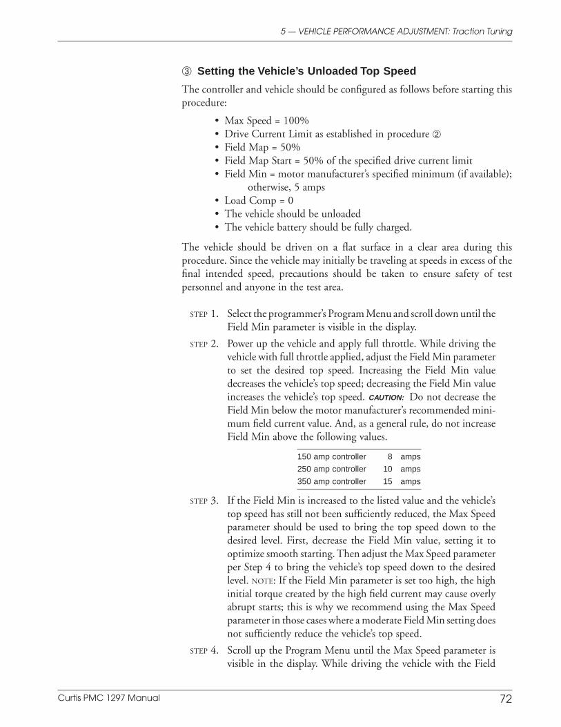
Curtis PMC 1297 Manual 72
Preliminary on Verso page is set with right edge at 7 and 7/8,
and the top (as on the Recto page) at 1/4.
➂ Setting the Vehicle’s Unloaded Top Speed
The controller and vehicle should be configured as follows before starting thisprocedure:
• Max Speed = 100%• Drive Current Limit as established in procedure ➁• Field Map = 50%• Field Map Start = 50% of the specified drive current limit• Field Min = motor manufacturer’s specified minimum (if available);
otherwise, 5 amps• Load Comp = 0• The vehicle should be unloaded• The vehicle battery should be fully charged.
The vehicle should be driven on a flat surface in a clear area during thisprocedure. Since the vehicle may initially be traveling at speeds in excess of thefinal intended speed, precautions should be taken to ensure safety of testpersonnel and anyone in the test area.
STEP 1. Select the programmer’s Program Menu and scroll down until theField Min parameter is visible in the display.
STEP 2. Power up the vehicle and apply full throttle. While driving thevehicle with full throttle applied, adjust the Field Min parameterto set the desired top speed. Increasing the Field Min valuedecreases the vehicle’s top speed; decreasing the Field Min valueincreases the vehicle’s top speed. CAUTION: Do not decrease theField Min below the motor manufacturer’s recommended mini-mum field current value. And, as a general rule, do not increaseField Min above the following values.
150 amp controller 8 amps
250 amp controller 10 amps
350 amp controller 15 amps
STEP 3. If the Field Min is increased to the listed value and the vehicle’stop speed has still not been sufficiently reduced, the Max Speedparameter should be used to bring the top speed down to thedesired level. First, decrease the Field Min value, setting it tooptimize smooth starting. Then adjust the Max Speed parameterper Step 4 to bring the vehicle’s top speed down to the desiredlevel. NOTE: If the Field Min parameter is set too high, the highinitial torque created by the high field current may cause overlyabrupt starts; this is why we recommend using the Max Speedparameter in those cases where a moderate Field Min setting doesnot sufficiently reduce the vehicle’s top speed.
STEP 4. Scroll up the Program Menu until the Max Speed parameter isvisible in the display. While driving the vehicle with the Field
5 — VEHICLE PERFORMANCE ADJUSTMENT: Traction Tuning
Curtis PMC 1297 Manual 73
Preliminary on Verso page is set with right edge at 7 and 7/8,
and the top (as on the Recto page) at 1/4.
Min set at the value selected in Step 3, decrease the Max Speedparameter value until the desired vehicle top speed is set.
STEP 5. For Walkie/Rider Applications: Typically, different top speeds aredesired for walkie and rider operation. To tune a walkie/ridervehicle’s top speed, first tune it for rider operation by using theField Min parameter. Then, to set the top speed for walkieoperation, leave the Field Min parameter alone and decrease theMax Speed parameter until the desired walking vehicle speed isreached.
Equalization of Loaded and Unloaded Vehicle Speed
The top speed of a loaded vehicle can be set to approach the unloaded top speedby tuning the controller’s Field Map Start and Load Compensation parameters.It is recommended that you review the description of the Field Map Start andLoad Compensation parameters in Section 3 before starting this procedure.
STEP 1. The vehicle’s unloaded top speed should already have been set. Ifit was not, it should be set before the vehicle’s loaded top speedis established.
STEP 2. Once the vehicle’s unloaded top speed has been set, load thevehicle to its desired load capacity. Leave the Field Min and MaxSpeed parameters at the settings determined during the unloadedtest.
STEP 3A. If the intent is to minimize the difference between the loaded andunloaded vehicle speeds, then:(i) Drive the fully loaded vehicle on flat ground with full throttleapplied. When the vehicle reaches maximum speed, observe thearmature current displayed in the programmer’s Test Menu.(ii) Set the Field Map Start parameter slightly higher than theobserved armature current value.(iii) Test the loaded/unloaded speed variation. If the observedvariation is unacceptable, proceed to “(iv).”(iv) Increase the Load Comp parameter and retest the speedregulation. The Load Comp parameter can be increased until thedesired regulation is achieved or the vehicle begins to oscillate(“hunt”) at low throttle. If the loaded/unloaded speed variationis acceptable but the average speed is not, adjustments can bemade to the Field Min parameter.
STEP 3B. If the intent is to make the loaded speed less than the unloadedspeed (for reasons of safety, efficiency, or reduced motor heating),then:(i) Unload the vehicle and drive it on flat ground with full throttleapplied. When the vehicle reaches maximum speed, observe the
5 — VEHICLE PERFORMANCE ADJUSTMENT: Traction Tuning
Curtis PMC 1297 Manual 74
Preliminary on Verso page is set with right edge at 7 and 7/8,
and the top (as on the Recto page) at 1/4.
armature current displayed in the programmer’s Test Menu.(ii) Set the Field Map Start parameter to the observed armaturecurrent value.(iii) Load the vehicle and drive it on flat ground with full throttleapplied. Further adjustments to the vehicle’s loaded speed cannow be made by varying the Field Map parameter. Increasing theField Map value will decrease the vehicle’s loaded speed, anddecreasing the Field Map value will increase the vehicle’s loadedspeed.
CAUTION: If the Field Map Start parameter is set too high, the motor’s safecommutation region may be exceeded. If this is the case, reduce the FieldMap Start parameter to a safe value. Then, adjust the Field Mapparameter as needed to reach the desired loaded top speed. Reducing theField Map value will help bring the loaded speed closer to the unloadedspeed. However, care must still be taken because it is possible for too lowField Map values—like too high Field Map Start values—to result inexceeding the motor’s safe commutation region.
TRACTION: FINE TUNING
Four additional vehicle performance characteristics can be adjusted:
➄ Response to reduced throttle
Response to increased throttle
Smoothness of direction transitions
Ramp climbing.
These characteristics are related to the “feel” of the vehicle and will be differentfor various applications. Once the fine tuning has been accomplished, it shouldnot have to be repeated on every vehicle.
Typically, Mode 1 is configured for precision maneuvering, with the sixMode 1 parameters (M1 Drive Current Limit, M1 Braking Current Limit, M1Accel Rate, M1 Decel Rate, M1 Braking Rate, and M1 Maximum Speed) tunedexclusively to provide comfortable vehicle response at low speeds.
➄ Response to Reduced Throttle
The way the vehicle behaves when the throttle is reduced or completely releasedcan be adjusted to suit your application, using the Decel Rate and Restraintparameters. Refer to the description of these parameters in Section 3 beforebeginning this procedure.
STEP 1. Set the Decel Rate based on the desired time for the vehicle tostop upon release of throttle when traveling at full speed with fullload. If the vehicle brakes too abruptly when the throttle isreleased, increase the Decel Rate.
5 — VEHICLE PERFORMANCE ADJUSTMENT: Traction Tuning
Curtis PMC 1297 Manual 75
i
and the top (as on the Recto page) at 1/4.
STEP 2. The default Restraint setting (8 amps) should work well for mostvehicles. If the vehicle exhibits excessive overspeed when drivingdown a ramp, increase the Restraint value. If the vehicle “speedhunts” while driving down a ramp or brakes too abruptly at lowor released throttle, decrease the Restraint value.
STEP 3. If the Restraint value has been adjusted, retest braking behaviorwhen throttle is reduced to ensure that it still has the desired feel.If it does not, the Decel Rate should be re-adjusted as in Step 1.
Response to Increased Throttle
The way the vehicle reacts to quick or slow increased throttle requests can bemodified using the Accel Rate, Current Ratio, and Throttle Map parameters.Optimal vehicle response is tuned by adjusting these parameters and thenaccelerating the vehicle from a dead stop under various throttle transitionconditions.
STEP 1. Set Throttle Map = 50%.
STEP 2. Drive the vehicle and adjust the Accel Rate for the best overallresponse. If the vehicle starts too slowly under all driving condi-tions, the Accel Rate should be reduced.
STEP 3. Increasing vehicle acceleration. If acceleration feels good for slowor moderate throttle transitions but the vehicle initially starts tooslowly, set the Current Ratio parameter to 2 or higher.
STEP 4. Achieving better control at low speeds. If the vehicle respondswell for fast, full range throttle transitions but is too jumpyduring low speed maneuvering, reduce the Throttle Map and/orset the Current Ratio to 1.
Smoothness of Direction Transitions
Additional fine tuning can be performed to enhance the vehicle’s transitionsbetween braking and driving.
STEP 1. Ensure that the Braking Rate parameter has been set for the desiredresponse (see Section 3A, page 25).
STEP 2. If the transition is too abrupt: increase the Taper Rate and/or setthe Variable Braking parameter to On. Secondary adjustmentscan be made by increasing the Accel Rate.
STEP 3. If the transition is too slow: decrease the Taper Rate and setCreep Speed to 5% or greater. Secondary adjustments can bemade by decreasing the Accel Rate or increasing the CurrentRatio.
5 — VEHICLE PERFORMANCE ADJUSTMENT: Traction Tuning

Curtis PMC 1297 Manual 76
Preliminary on Verso page is set with right edge at 7 and 7/8,
and the top (as on the Recto page) at 1/4.
Ramp Climbing
The vehicle’s response to increased gradients such as loading ramps can be tunedvia the Field Map parameter. Decreasing the Field Map parameter allows fastervehicle speeds while climbing ramps, but it also has the effect of reducing theability of the controller to generate torque in the vehicle’s mid-range speeds.
STEP 1. If faster vehicle speed is desired when climbing ramps, decreasethe Field Map parameter value until the desired ramp climbingspeed is attained. It should be noted that if the motor’s torquecapability is exceeded under the conditions of load weight andramp gradient, vehicle speed will be limited by the motor’scapability and the desired vehicle speed may not be attainable.The system will find a compromise point at which sufficientmotor torque is generated to climb the ramp at an acceptablespeed. If the Field Map parameter value is reduced to 0% and thedesired speed is still not attained, the system is being limited bythe motor’s torque capability under these operating conditions.CAUTION: be careful when reducing the Field Map parametersince at low Field Map values it is possible that the motor couldbe operated outside its safe commutation region.
STEP 2. If the drive system cannot produce sufficient torque for a fullyloaded vehicle to climb the desired ramp, try increasing the FieldMap, Field Max, and/or Drive Current Limit parameters. Theimpact of increasing these parameter values on other drivingcharacteristics must be evaluated. Increasing the Field Max willprovide more field current, and increasing the Drive CurrentLimit will provide more armature current. If the Field Max is setat the manufacturer’s specified limit and the Drive Current Limitis set at the rated maximum, then vehicle speed up the ramp islimited by the motor or the vehicle’s gearing and cannot beincreased by tuning the controller. NOTE: To determine whetherthe controller’s armature current is at its set value during rampclimbing, read the Arm Current value in the programmer’s TestMenu.
5 — VEHICLE PERFORMANCE ADJUSTMENT: Traction Tuning
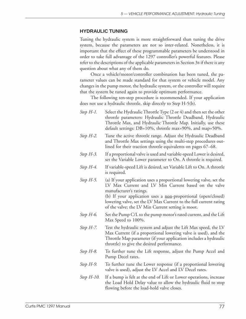
Curtis PMC 1297 Manual 77
Preliminary on Verso page is set with right edge at 7 and 7/8,
and the top (as on the Recto page) at 1/4.
HYDRAULIC TUNING
Tuning the hydraulic system is more straightforward than tuning the drivesystem, because the parameters are not so inter-related. Nonetheless, it isimportant that the effect of these programmable parameters be understood inorder to take full advantage of the 1297 controller’s powerful features. Pleaserefer to the descriptions of the applicable parameters in Section 3B if there is anyquestion about what any of them do.
Once a vehicle/motor/controller combination has been tuned, the pa-rameter values can be made standard for that system or vehicle model. Anychanges in the pump motor, the hydraulic system, or the controller will requirethat the system be tuned again to provide optimum performance.
The following ten-step procedure is recommended. If your applicationdoes not use a hydraulic throttle, skip directly to Step H-5(b).
Step H-1. Select the Hydraulic Throttle Type (2 or 4) and then set the otherthrottle parameters: Hydraulic Throttle Deadband, HydraulicThrottle Max, and Hydraulic Throttle Map. Initially, use thesedefault settings: DB=10%, throttle max=90%, and map=50%.
Step H-2. Tune the active throttle range. Adjust the Hydraulic Deadbandand Throttle Max settings using the multi-step procedures out-lined for their traction throttle equivalents on pages 67–68.
Step H-3. If a proportional valve is used and variable-speed Lower is desired,set the Variable Lower parameter to On. A throttle is required.
Step H-4. If variable-speed Lift is desired, set Variable Lift to On. A throttleis required.
Step H-5. (a) If your application uses a proportional lowering valve, set theLV Max Current and LV Min Current based on the valvemanufacturer’s ratings.(b) If your application uses a non-proportional (open/closed)lowering valve, set the LV Max Current to the full current ratingof the valve; the LV Min Current setting is moot.
Step H-6. Set the Pump C/L to the pump motor’s rated current, and the LiftMax Speed to 100%.
Step H-7. Test the hydraulic system and adjust the Lift Max speed, the LVMax Current (if a proportional lowering valve is used), and theThrottle Map parameter (if your application includes a hydraulicthrottle) to give the desired performance.
Step H-8. To further tune the Lift response, adjust the Pump Accel andPump Decel rates.
Step H-9. To further tune the Lower response (if a proportional loweringvalve is used), adjust the LV Accel and LV Decel rates.
Step H-10. If a bump is felt at the end of Lift or Lower operations, increasethe Load Hold Delay value to allow the hydraulic fluid to stopflowing before the load-hold valve closes.
5 — VEHICLE PERFORMANCE ADJUSTMENT: Hydraulic Tuning
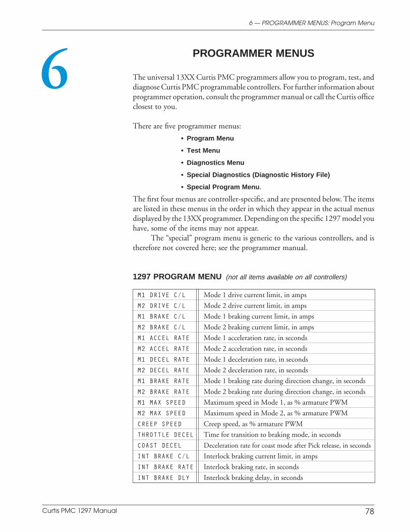
Curtis PMC 1297 Manual 78
Preliminary on Verso page is set with right edge at 7 and 7/8,
and the top (as on the Recto page) at 1/4.
6 — PROGRAMMER MENUS: Program Menu
6 PROGRAMMER MENUS
The universal 13XX Curtis PMC programmers allow you to program, test, anddiagnose Curtis PMC programmable controllers. For further information aboutprogrammer operation, consult the programmer manual or call the Curtis officeclosest to you.
There are five programmer menus:
• Program Menu
• Test Menu
• Diagnostics Menu
• Special Diagnostics (Diagnostic History File)
• Special Program Menu.
The first four menus are controller-specific, and are presented below. The itemsare listed in these menus in the order in which they appear in the actual menusdisplayed by the 13XX programmer. Depending on the specific 1297 model youhave, some of the items may not appear.
The “special” program menu is generic to the various controllers, and istherefore not covered here; see the programmer manual.
1297 PROGRAM MENU (not all items available on all controllers)
M1 DRIVE C/L Mode 1 drive current limit, in amps
M2 DRIVE C/L Mode 2 drive current limit, in amps
M1 BRAKE C/L Mode 1 braking current limit, in amps
M2 BRAKE C/L Mode 2 braking current limit, in amps
M1 ACCEL RATE Mode 1 acceleration rate, in seconds
M2 ACCEL RATE Mode 2 acceleration rate, in seconds
M1 DECEL RATE Mode 1 deceleration rate, in seconds
M2 DECEL RATE Mode 2 deceleration rate, in seconds
M1 BRAKE RATE Mode 1 braking rate during direction change, in seconds
M2 BRAKE RATE Mode 2 braking rate during direction change, in seconds
M1 MAX SPEED Maximum speed in Mode 1, as % armature PWM
M2 MAX SPEED Maximum speed in Mode 2, as % armature PWM
CREEP SPEED Creep speed, as % armature PWM
THROTTLE DECEL Time for transition to braking mode, in seconds
COAST DECEL Deceleration rate for coast mode after Pick release, in seconds
INT BRAKE C/L Interlock braking current limit, in amps
INT BRAKE RATE Interlock braking rate, in seconds
INT BRAKE DLY Interlock braking delay, in seconds
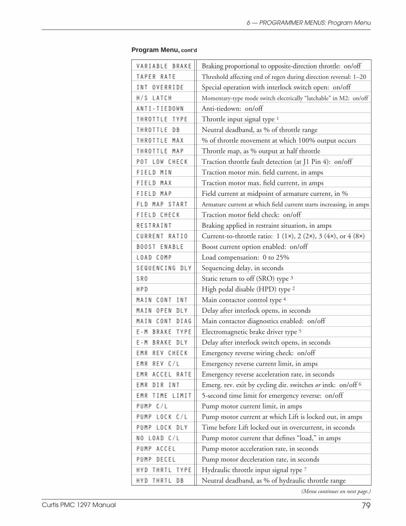
Curtis PMC 1297 Manual 79
Preliminary on Verso page is set with right edge at 7 and 7/8,
and the top (as on the Recto page) at 1/4.
VARIABLE BRAKE Braking proportional to opposite-direction throttle: on/off
TAPER RATE Threshold affecting end of regen during direction reversal: 1–20
INT OVERRIDE Special operation with interlock switch open: on/off
H/S LATCH Momentary-type mode switch electrically “latchable” in M2: on/off
ANTI-TIEDOWN Anti-tiedown: on/off
THROTTLE TYPE Throttle input signal type 1
THROTTLE DB Neutral deadband, as % of throttle range
THROTTLE MAX % of throttle movement at which 100% output occurs
THROTTLE MAP Throttle map, as % output at half throttle
POT LOW CHECK Traction throttle fault detection (at J1 Pin 4): on/off
FIELD MIN Traction motor min. field current, in amps
FIELD MAX Traction motor max. field current, in amps
FIELD MAP Field current at midpoint of armature current, in %
FLD MAP START Armature current at which field current starts increasing, in amps
FIELD CHECK Traction motor field check: on/off
RESTRAINT Braking applied in restraint situation, in amps
CURRENT RATIO Current-to-throttle ratio: 1 (1×), 2 (2×), 3 (4×), or 4 (8×)
BOOST ENABLE Boost current option enabled: on/off
LOAD COMP Load compensation: 0 to 25%
SEQUENCING DLY Sequencing delay, in seconds
SRO Static return to off (SRO) type 3
HPD High pedal disable (HPD) type 2
MAIN CONT INT Main contactor control type 4
MAIN OPEN DLY Delay after interlock opens, in seconds
MAIN CONT DIAG Main contactor diagnostics enabled: on/off
E-M BRAKE TYPE Electromagnetic brake driver type 5
E-M BRAKE DLY Delay after interlock switch opens, in seconds
EMR REV CHECK Emergency reverse wiring check: on/off
EMR REV C/L Emergency reverse current limit, in amps
EMR ACCEL RATE Emergency reverse acceleration rate, in seconds
EMR DIR INT Emerg. rev. exit by cycling dir. switches or intk: on/off 6
EMR TIME LIMIT 5-second time limit for emergency reverse: on/off
PUMP C/L Pump motor current limit, in amps
PUMP LOCK C/L Pump motor current at which Lift is locked out, in amps
PUMP LOCK DLY Time before Lift locked out in overcurrent, in seconds
NO LOAD C/L Pump motor current that defines “load,” in amps
PUMP ACCEL Pump motor acceleration rate, in seconds
PUMP DECEL Pump motor deceleration rate, in seconds
HYD THRTL TYPE Hydraulic throttle input signal type 7
HYD THRTL DB Neutral deadband, as % of hydraulic throttle range
6 — PROGRAMMER MENUS: Program Menu
Program Menu, cont’d
(Menu continues on next page.)
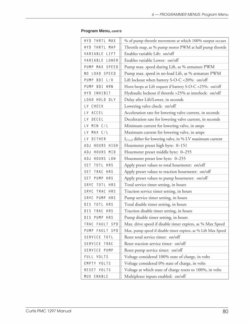
Curtis PMC 1297 Manual 80
Preliminary on Verso page is set with right edge at 7 and 7/8,
and the top (as on the Recto page) at 1/4.
HYD THRTL MAX % of pump throttle movement at which 100% output occurs
HYD THRTL MAP Throttle map, as % pump motor PWM at half pump throttle
VARIABLE LIFT Enables variable Lift: on/off
VARIABLE LOWER Enables variable Lower: on/off
PUMP MAX SPEED Pump max. speed during Lift, as % armature PWM
NO LOAD SPEED Pump max. speed in no-load Lift, as % armature PWM
PUMP BDI L/O Lift lockout when battery S-O-C <20%: on/off
PUMP BDI WRN Horn beeps at Lift request if battery S-O-C <25%: on/off
HYD INHIBIT Hydraulic lockout if throttle >25% at interlock: on/off
LOAD HOLD DLY Delay after Lift/Lower, in seconds
LV CHECK Lowering valve check: on/off
LV ACCEL Acceleration rate for lowering valve current, in seconds
LV DECEL Deceleration rate for lowering valve current, in seconds
LV MIN C/L Minimum current for lowering valve, in amps
LV MAX C/L Maximum current for lowering valve, in amps
LV DITHER ILVcoil dither for lowering valve, in % LV maximum current
ADJ HOURS HIGH Hourmeter preset high byte: 0–151
ADJ HOURS MID Hourmeter preset middle byte: 0–255
ADJ HOURS LOW Hourmeter preset low byte: 0–255
SET TOTL HRS Apply preset values to total hourmeter: on/off
SET TRAC HRS Apply preset values to traction hourmeter: on/off
SET PUMP HRS Apply preset values to pump hourmeter: on/off
SRVC TOTL HRS Total service timer setting, in hours
SRVC TRAC HRS Traction service timer setting, in hours
SRVC PUMP HRS Pump service timer setting, in hours
DIS TOTL HRS Total disable timer setting, in hours
DIS TRAC HRS Traction disable timer setting, in hours
DIS PUMP HRS Pump disable timer setting, in hours
TRAC FAULT SPD Max. drive speed if disable timer expires, as % Max Speed
PUMP FAULT SPD Max. pump speed if disable timer expires, as % Lift Max Speed
SERVICE TOTL Reset total service timer: on/off
SERVICE TRAC Reset traction service timer: on/off
SERVICE PUMP Reset pump service timer: on/off
FULL VOLTS Voltage considered 100% state of charge, in volts
EMPTY VOLTS Voltage considered 0% state of charge, in volts
RESET VOLTS Voltage at which state of charge resets to 100%, in volts
MUX ENABLE Multiplexer inputs enabled: on/off
Program Menu, cont’d
6 — PROGRAMMER MENUS: Program Menu
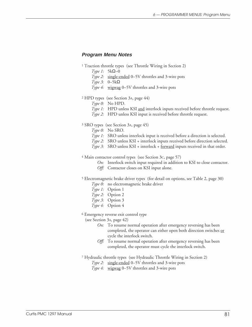
Curtis PMC 1297 Manual 81
Preliminary on Verso page is set with right edge at 7 and 7/8,
and the top (as on the Recto page) at 1/4.
Program Menu Notes
1 Traction throttle types (see Throttle Wiring in Section 2)Type 1: 5kΩ–0Type 2: single-ended 0–5V throttles and 3-wire potsType 3: 0–5kΩType 4: wigwag 0–5V throttles and 3-wire pots
2 HPD types (see Section 3A, page 44)Type 0: No HPD.Type 1: HPD unless KSI and interlock inputs received before throttle request.Type 2: HPD unless KSI input is received before throttle request.
3 SRO types (see Section 3A, page 45)Type 0: No SRO.Type 1: SRO unless interlock input is received before a direction is selected.Type 2: SRO unless KSI + interlock inputs received before direction selected.Type 3: SRO unless KSI + interlock + forward inputs received in that order.
4 Main contactor control types (see Section 3C, page 57)On: Interlock switch input required in addition to KSI to close contactor.Off: Contactor closes on KSI input alone.
5 Electromagnetic brake driver types (for detail on options, see Table 2, page 30)Type 0: no electromagnetic brake driverType 1: Option 1Type 2: Option 2Type 3: Option 3Type 4: Option 4
6 Emergency reverse exit control type (see Section 3A, page 42)
On: To resume normal operation after emergency reversing has beencompleted, the operator can either open both direction switches orcycle the interlock switch.
Off: To resume normal operation after emergency reversing has beencompleted, the operator must cycle the interlock switch.
7 Hydraulic throttle types (see Hydraulic Throttle Wiring in Section 2)Type 2: single-ended 0–5V throttles and 3-wire potsType 4: wigwag 0–5V throttles and 3-wire pots
6 — PROGRAMMER MENUS: Program Menu

Curtis PMC 1297 Manual 82
Preliminary on Verso page is set with right edge at 7 and 7/8,
and the top (as on the Recto page) at 1/4.
1297 TEST MENU (not all items available on all controllers)
BATT VOLTAGE Battery voltage across B+ and B-, in volts
BDI % Battery state of charge, as % of full charge
HEATSINK TEMP Heatsink temperature, in °CTHROTTLE % Throttle reading, as % of full throttle
FIELD CURRENT Traction motor field current, in amps
ARM CURRENT Traction motor armature current, in amps
FIELD PWM Traction motor field duty cycle, as %
ARM PWM Traction motor armature duty cycle, as %
FORWARD INPUT Forward switch: on/off [neutral switch for Type 4 throttle]
REVERSE INPUT Reverse switch: on/off
MODE INPUT Mode switch: on (M2)/off (M1)
EMR REV INPUT Emergency reverse switch: on/off
HYD THROTTLE % Hydraulic throttle reading, as % of full throttle
PUMP CURRENT Pump motor current, in amps
PUMP PWM Pump motor duty cycle, as %
LV CURRENT Lowering valve current, in amps
LV PWM Lowering valve duty cycle, as %
LIFT INPUT Lift switch: on/off
LOWER INPUT Lower switch: on/off
MAIN CONT Main contactor: open/closed
E-M BRAKE Electromagnetic brake: on/off
HORN INPUT Horn driver: on/off
LOAD HOLD Load-hold valve driver: on/off
6 — PROGRAMMER MENUS: Test Menu
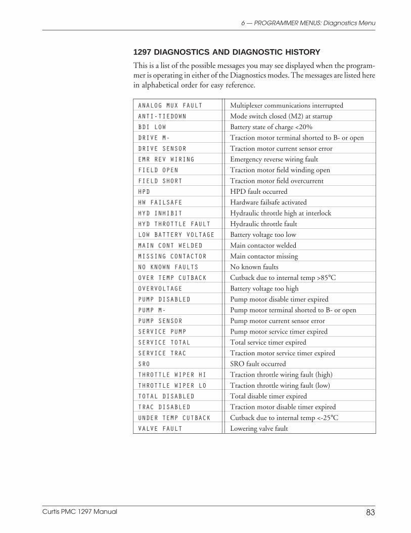
Curtis PMC 1297 Manual 83
Preliminary on Verso page is set with right edge at 7 and 7/8,
and the top (as on the Recto page) at 1/4.
6 — PROGRAMMER MENUS: Diagnostics Menu
1297 DIAGNOSTICS AND DIAGNOSTIC HISTORY
This is a list of the possible messages you may see displayed when the program-mer is operating in either of the Diagnostics modes. The messages are listed herein alphabetical order for easy reference.
ANALOG MUX FAULT Multiplexer communications interrupted
ANTI-TIEDOWN Mode switch closed (M2) at startup
BDI LOW Battery state of charge <20%
DRIVE M- Traction motor terminal shorted to B- or open
DRIVE SENSOR Traction motor current sensor error
EMR REV WIRING Emergency reverse wiring fault
FIELD OPEN Traction motor field winding open
FIELD SHORT Traction motor field overcurrent
HPD HPD fault occurred
HW FAILSAFE Hardware failsafe activated
HYD INHIBIT Hydraulic throttle high at interlock
HYD THROTTLE FAULT Hydraulic throttle fault
LOW BATTERY VOLTAGE Battery voltage too low
MAIN CONT WELDED Main contactor welded
MISSING CONTACTOR Main contactor missing
NO KNOWN FAULTS No known faults
OVER TEMP CUTBACK Cutback due to internal temp >85°COVERVOLTAGE Battery voltage too high
PUMP DISABLED Pump motor disable timer expired
PUMP M- Pump motor terminal shorted to B- or open
PUMP SENSOR Pump motor current sensor error
SERVICE PUMP Pump motor service timer expired
SERVICE TOTAL Total service timer expired
SERVICE TRAC Traction motor service timer expired
SRO SRO fault occurred
THROTTLE WIPER HI Traction throttle wiring fault (high)
THROTTLE WIPER LO Traction throttle wiring fault (low)
TOTAL DISABLED Total disable timer expired
TRAC DISABLED Traction motor disable timer expired
UNDER TEMP CUTBACK Cutback due to internal temp <-25°CVALVE FAULT Lowering valve fault

Curtis PMC 1297 Manual 84
Preliminary on Verso page is set with right edge at 7 and 7/8,
and the top (as on the Recto page) at 1/4.
7 — DIAGNOSTICS & TROUBLESHOOTING
7 DIAGNOSTICS AND TROUBLESHOOTING
The 1297 controller provides diagnostics information to assist technicians introubleshooting pump system problems. The diagnostics information can beobtained by observing the appropriate display on a 13XX programmer, the faultcodes issued by the Status LED, or the fault display on the Spyglass gauge. Referto the troubleshooting chart (Table 5) for suggestions covering a wide range ofpossible faults.
PROGRAMMER DIAGNOSTICS
The programmer presents complete diagnostic information in plain language.Faults are displayed in the Diagnostics Menu (see column 2 in the troubleshoot-ing chart), and the status of the controller inputs/outputs is displayed in the TestMenu.
Accessing the Diagnostic History Menu provides a list of the faults thathave occurred since the diagnostic history file was last cleared. Checking (andclearing) the diagnostic history file is recommended each time the vehicle isbrought in for maintenance.
The following 4-step diagnostic and troubleshooting process is recom-mended: (1) visually inspect the vehicle for obvious problems; (2) diagnose theproblem, using the programmer; (3) test the circuitry with the programmer;and (4) correct the problem. Repeat the last three steps as necessary until thepump system is operational.
Example: A vehicle that does not operate in “forward” is brought infor repair.
STEP 1: Examine the vehicle and its wiring for any obvious problems,such as broken wires or loose connections.
STEP 2: Connect the programmer, select the Diagnostics Menu, andread the displayed fault information. In this example, the displayshows “No Known Faults,” indicating that the controller has notdetected anything out of the norm.
STEP 3: Select the Test Menu, and observe the status of the inputs andoutputs in the forward direction. In this example, the display showsthat the forward switch did not close when “forward” was selected,which means the problem is either in the forward switch or the switchwiring.
STEP 4: Check or replace the forward switch and wiring and repeat thetest. If the programmer shows the forward switch closing and thesystem now operates normally, the problem has been corrected.
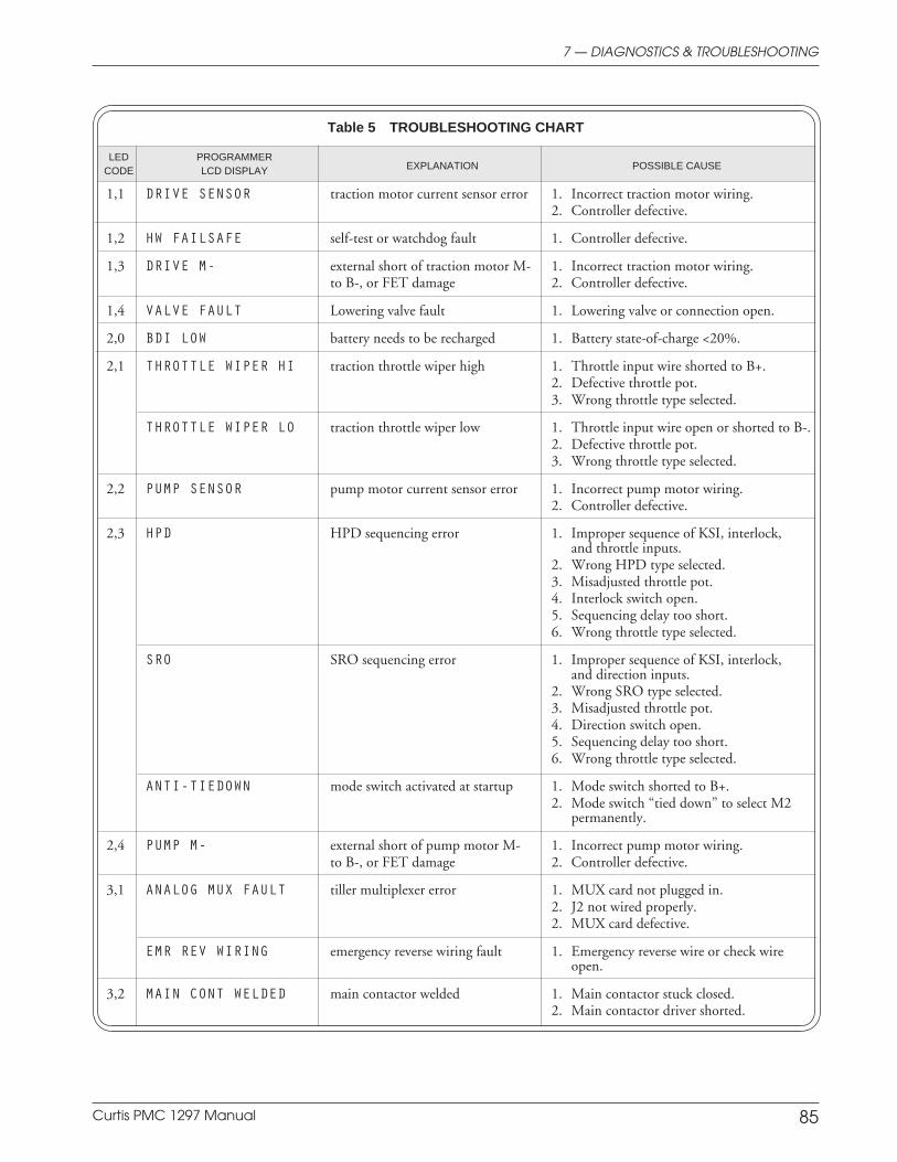
Curtis PMC 1297 Manual 85
Preliminary on Verso page is set with right edge at 7 and 7/8,
and the top (as on the Recto page) at 1/4.
7 — DIAGNOSTICS & TROUBLESHOOTING
Table 5 TROUBLESHOOTING CHART
LED PROGRAMMERCODE LCD DISPLAY EXPLANATION POSSIBLE CAUSE
1,1 DRIVE SENSOR traction motor current sensor error 1. Incorrect traction motor wiring.2. Controller defective.
1,2 HW FAILSAFE self-test or watchdog fault 1. Controller defective.
1,3 DRIVE M- external short of traction motor M- 1. Incorrect traction motor wiring.to B-, or FET damage 2. Controller defective.
1,4 VALVE FAULT Lowering valve fault 1. Lowering valve or connection open.
2,0 BDI LOW battery needs to be recharged 1. Battery state-of-charge <20%.
2,1 THROTTLE WIPER HI traction throttle wiper high 1. Throttle input wire shorted to B+.2. Defective throttle pot.3. Wrong throttle type selected.
THROTTLE WIPER LO traction throttle wiper low 1. Throttle input wire open or shorted to B-.2. Defective throttle pot.3. Wrong throttle type selected.
2,2 PUMP SENSOR pump motor current sensor error 1. Incorrect pump motor wiring.2. Controller defective.
2,3 HPD HPD sequencing error 1. Improper sequence of KSI, interlock,and throttle inputs.
2. Wrong HPD type selected.3. Misadjusted throttle pot.4. Interlock switch open.5. Sequencing delay too short.6. Wrong throttle type selected.
SRO SRO sequencing error 1. Improper sequence of KSI, interlock,and direction inputs.
2. Wrong SRO type selected.3. Misadjusted throttle pot.4. Direction switch open.5. Sequencing delay too short.6. Wrong throttle type selected.
ANTI-TIEDOWN mode switch activated at startup 1. Mode switch shorted to B+.2. Mode switch “tied down” to select M2
permanently.
2,4 PUMP M- external short of pump motor M- 1. Incorrect pump motor wiring.to B-, or FET damage 2. Controller defective.
3,1 ANALOG MUX FAULT tiller multiplexer error 1. MUX card not plugged in.2. J2 not wired properly.2. MUX card defective.
EMR REV WIRING emergency reverse wiring fault 1. Emergency reverse wire or check wireopen.
3,2 MAIN CONT WELDED main contactor welded 1. Main contactor stuck closed.2. Main contactor driver shorted.
[chart continues on next page]

Curtis PMC 1297 Manual 86
Preliminary on Verso page is set with right edge at 7 and 7/8,
and the top (as on the Recto page) at 1/4.
3,3 FIELD SHORT traction motor field shorted 1. Field resistance too low.2. Field winding shorted to B+ or B-.
FIELD OPEN traction motor field open 1. Field winding or connection open.
3,4 MISSING CONTACTOR missing main contactor 1. Main contactor coil open.2. Main contactor missing.3. Wire to main contactor missing.
4,0 TOTAL DISABLED expired total disable timer 1. Total disable timer expired.
TRAC DISABLED expired traction disable timer 1. Traction disable timer expired.
PUMP DISABLED expired pump disable timer 1. Pump disable timer expired.
4,1 SERVICE TOTAL expired total maintenance monitor 1. Total maintenance monitor expired.
SERVICE TRAC expired traction maintenance monitor 1. Traction maintenance monitor expired.
SERVICE PUMP expired pump maintenance monitor 1. Pump maintenance monitor expired.
4,2 OVERVOLTAGE battery voltage too high 1. Battery voltage > overvoltageshutdown limit.
2. Operation with charger attached.
LOW BATTERY VOLTAGE battery voltage too low 1. Battery voltage < undervoltagecutback limit.
2. Corroded battery terminal.3. Loose battery or controller terminal.
4,3 OVER TEMP CUTBACK controller heatsink too hot 1. Temperature >85°C.2. Excessive load on vehicle.3. Improper mounting of controller.4. Operation in extreme environments.
UNDER TEMP CUTBACK controller heatsink too cold 1. Temperature < -25°C.3. Operation in extreme environments.
4,4 HYD THROTTLE FAULT hydraulic throttle fault 1. Throttle input wire shorted to B+ or B-.2. Throttle input wire open.3. Defective throttle pot.4. Wrong throttle type selected.
HYD INHIBIT hydraulic throttle high at interlock 1. Improper sequence of interlock andthrottle inputs.
2. Misadjusted throttle pot.3. Interlock switch open.4. Sequencing delay too short.5. Wrong throttle type selected.
Table 5 TROUBLESHOOTING CHART, continued
LED PROGRAMMERCODE LCD DISPLAY EXPLANATION POSSIBLE CAUSE
7 — DIAGNOSTICS & TROUBLESHOOTING
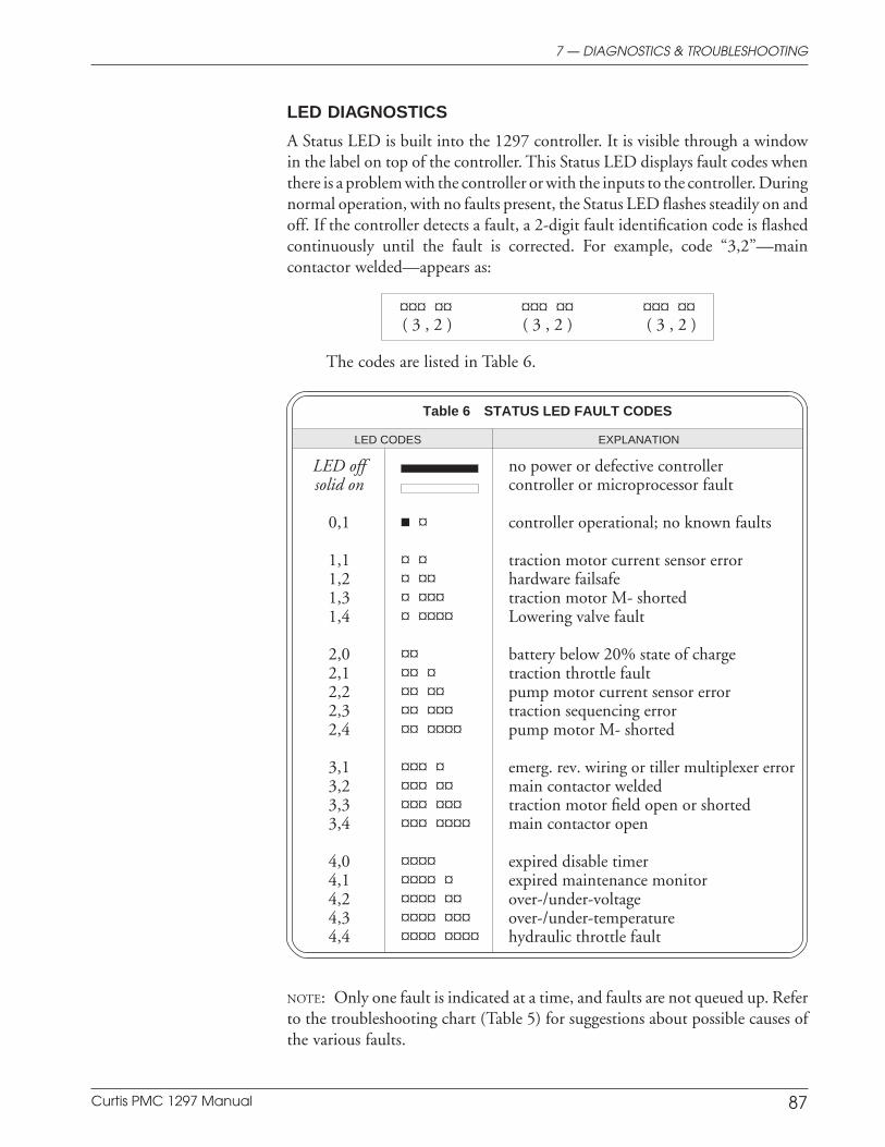
Curtis PMC 1297 Manual 87
Preliminary on Verso page is set with right edge at 7 and 7/8,
and the top (as on the Recto page) at 1/4.
7 — DIAGNOSTICS & TROUBLESHOOTING
LED DIAGNOSTICS
A Status LED is built into the 1297 controller. It is visible through a windowin the label on top of the controller. This Status LED displays fault codes whenthere is a problem with the controller or with the inputs to the controller. Duringnormal operation, with no faults present, the Status LED flashes steadily on andoff. If the controller detects a fault, a 2-digit fault identification code is flashedcontinuously until the fault is corrected. For example, code “3,2”—maincontactor welded—appears as:
¤¤¤ ¤¤ ¤¤¤ ¤¤ ¤¤¤ ¤¤( 3 , 2 ) ( 3 , 2 ) ( 3 , 2 )
The codes are listed in Table 6.
Table 6 STATUS LED FAULT CODES
LED CODES EXPLANATION
LED off no power or defective controllersolid on controller or microprocessor fault
0,1 ¤ controller operational; no known faults
1,1 ¤ ¤ traction motor current sensor error1,2 ¤ ¤¤ hardware failsafe1,3 ¤ ¤¤¤ traction motor M- shorted1,4 ¤ ¤¤¤¤ Lowering valve fault
2,0 ¤¤ battery below 20% state of charge2,1 ¤¤ ¤ traction throttle fault2,2 ¤¤ ¤¤ pump motor current sensor error2,3 ¤¤ ¤¤¤ traction sequencing error2,4 ¤¤ ¤¤¤¤ pump motor M- shorted
3,1 ¤¤¤ ¤ emerg. rev. wiring or tiller multiplexer error3,2 ¤¤¤ ¤¤ main contactor welded3,3 ¤¤¤ ¤¤¤ traction motor field open or shorted3,4 ¤¤¤ ¤¤¤¤ main contactor open
4,0 ¤¤¤¤ expired disable timer4,1 ¤¤¤¤ ¤ expired maintenance monitor4,2 ¤¤¤¤ ¤¤ over-/under-voltage4,3 ¤¤¤¤ ¤¤¤ over-/under-temperature4,4 ¤¤¤¤ ¤¤¤¤ hydraulic throttle fault
NOTE: Only one fault is indicated at a time, and faults are not queued up. Referto the troubleshooting chart (Table 5) for suggestions about possible causes ofthe various faults.
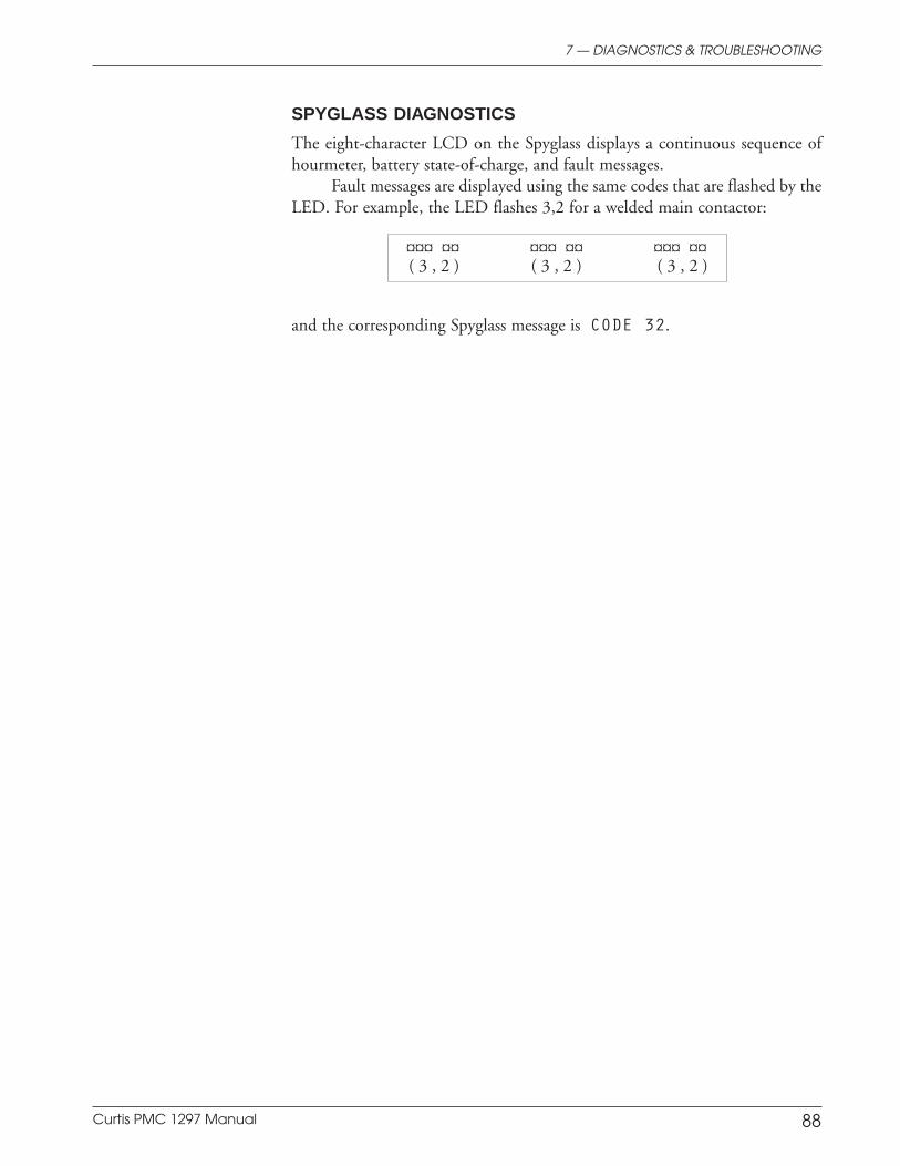
Curtis PMC 1297 Manual 88
Preliminary on Verso page is set with right edge at 7 and 7/8,
and the top (as on the Recto page) at 1/4.
7 — DIAGNOSTICS & TROUBLESHOOTING
SPYGLASS DIAGNOSTICS
The eight-character LCD on the Spyglass displays a continuous sequence ofhourmeter, battery state-of-charge, and fault messages.
Fault messages are displayed using the same codes that are flashed by theLED. For example, the LED flashes 3,2 for a welded main contactor:
¤¤¤ ¤¤ ¤¤¤ ¤¤ ¤¤¤ ¤¤( 3 , 2 ) ( 3 , 2 ) ( 3 , 2 )
and the corresponding Spyglass message is CODE 32.
Curtis PMC 1297 Manual 89
Preliminary on Verso page is set with right edge at 7 and 7/8,
and the top (as on the Recto page) at 1/4.
8 — MAINTENANCE
8 MAINTENANCE
There are no user serviceable parts in the Curtis PMC 1297 controller. Noattempt should be made to open, repair, or otherwise modify the controller.Doing so may damage the controller and will void the warranty.
It is recommended that the controller be kept clean and dry that itsdiagnostics history file be checked and cleared periodically.
CLEANING
Periodically cleaning the controller exterior will help protect it against corrosionand possible electrical control problems created by dirt, grime, and chemicalsthat are part of the operating environment and that normally exist in batterypowered systems.
When working around any battery powered system, proper safetyprecautions should be taken. These include, but are not limited to: propertraining, wearing eye protection, and avoiding loose clothing and jewelry.
Use the following cleaning procedure for routine maintenance. Never usea high pressure washer to clean the controller.
1. Remove power by disconnecting the battery.
2. Discharge the capacitors in the controller by connecting a load(such as a contactor coil) across the controller’s B+ and B-terminals.
3. Remove any dirt or corrosion from the power and signal connectorareas. The controller should be wiped clean with a moist rag.Dry it before reconnecting the battery.
4. Make sure the connections are tight. Refer to Section 2, page 7,for maximum tightening torque specifications for the batteryand motor connections.
DIAGNOSTIC HISTORY
The 13XX programmer can be used to access the controller’s diagnostic historyfile. The programmer will read out all the faults the controller has experiencedsince the last time the diagnostic history file was cleared. Faults such as contactorfaults may be the result of loose wires; contactor wiring should be carefullychecked. Faults such as overtemperature may be caused by operator habits or byoverloading.
After a problem has been diagnosed and corrected, it is a good idea toclear the diagnostic history file. This allows the controller to accumulate a newfile of faults. By checking the new diagnostic history file at a later date, you canreadily determine whether the problem was indeed fixed.
For instructions on accessing and clearing the diagnostic history file, seethe Curtis PMC 13XX programmer manual.
C A U T I O N

Curtis PMC 1297 Manual A-1
APPENDIX A: GLOSSARY
APPENDIX A
GLOSSARY OF FEATURES AND FUNCTIONS
Acceleration rate
The acceleration rate is the time required for the controller to increase PWMoutput from zero to the maximum allowed. There are four major programmableacceleration rates for the 1297 controller: the Mode 1 and Mode 2 accelerationrates (see Section 3A, page 24), which set how quickly the traction motoraccelerates; the pump acceleration rate (see Section 3B, page 47), which sets howquickly the pump motor accelerates during Lift operation; and the loweringvalve current acceleration rate (see Section 3B, page 49), which sets how quicklythe lowering valve aperture opens during Lower operation.
In addition, there is a separate acceleration rate for emergency reverse—see Section 3A, page 43.
Access rights
Each programmable parameter is assigned an access level (OEM or User) thatdefines who is allowed to adjust it. On generic 1297 models, all the program-mable parameters are assigned OEM access levels; see Table D-1. On OEM-specified models, the OEM designates the access level for each parameter.Restricting access rights to the OEM reduces the likelihood of importantperformance characteristics being changed by someone unfamiliar with thevehicle’s operation. In some cases, it may be necessary to restrict a parameter’saccess to ensure that it is not set to a value in violation of EEC or other safetyregulations.
Curtis PMC programmers are available in OEM and User models; theUser programmer can adjust only those parameters with User access rights,while the OEM programmer can adjust all the parameters. Typically, OEMssupply User programmers to their dealers and distributors for setting the User-access parameters (if any) to each customer’s liking, and also for testing anddiagnostics.
Anti-tiedown
The anti-tiedown feature is designed to discourage operators from taping orotherwise “tying down” the mode switch in order to operate permanently inMode 2—see Section 3A, page 44.
BDI
The 1297 controller has a built-in battery discharge indicator (BDI) thatconstantly calculates the battery state-of-charge whenever KSI is on—see Section3C, page 63.
Curtis PMC 1297 Manual A-2
APPENDIX A: GLOSSARY
Bidirectional throttle
A bidirectional (wigwag) throttle allows the operator to control vehicle speedand direction by rotating the throttle mechanism clockwise and counterclock-wise. The Curtis ET-XXX is an example of this throttle type.
Braking rate
The braking rate is the time required for the controller to increase from 0%braking output to 100% braking output when a new direction is selected—seeSection 3A, page 26.
Boost
The boost feature can provide a burst of extra torque when the controller detectsthat the traction motor is about to stall—see Section 3A, page 25.
Coast and pick
The coast and pick feature can be used to drive the vehicle a short distanceforward while the Pick switch is activated. When the Pick switch is released, thevehicle coasts to a stop—see Section 2, page 18, and Section 3A, page 26.
Creep speed
Creep speed is activated when a direction is first selected. The output maintainscreep speed until the throttle is rotated out of the throttle deadband (typically10% of throttle). This feature helps to prevent rollback when starting uphill withlow throttle—see Section 3A, page 31.
Current limiting
Curtis PMC controllers limit the traction motor’s drive current and the pumpmotor current to their programmed maximum values—see Section 3A, page 24,and Section 3B, page 46. Current limiting protects the controller from damagethat might result if the current were limited only by motor demand. PWMoutput is reduced until the motor current falls below the set limit.
In addition to protecting the controller, the current limit feature alsoprovides some protection to the rest of the system. By eliminating high currentsurges during acceleration, stress on the motors and batteries is reduced andtheir efficiency enhanced.
Current multiplication
During acceleration and during reduced speed operation, the Curtis PMCcontroller allows more current to flow into the motor than flows out of thebattery. The controller acts like a dc transformer, taking in low current and highvoltage (the full battery voltage) and putting out high current and low voltage.
Curtis PMC 1297 Manual A-3
APPENDIX A: GLOSSARY
Current ratio
The 1297 controller’s traction motor current limit increases linearly withincreased throttle. The current ratio parameter allows adjustment of the amountof current available at low throttle requests in order to maximize startup torquewhile maintaining smooth vehicle starts—see Section 3A, page 25.
Deceleration rate
The deceleration rate is the time required for the controller to decrease PWMoutput from the maximum allowed to zero, in response to reduced throttle.There are four major programmable deceleration rates for the 1297 controller: theMode 1 and Mode 2 deceleration rates (see Section 3A, page 26), which set howquickly the traction motor decelerates; the pump deceleration rate (see Section3B, page 47), which sets how quickly the pump motor decelerates during Liftoperation; and the lowering valve current deceleration rate (see Section 3B, page50), which sets how quickly the lowering valve aperture closes during Loweroperation.
See Coast and pick and Throttle deceleration for two additional decelera-tion rates for the traction motor.
Emergency reverse
Emergency reverse is activated when the emergency reverse switch is pressed.After the emergency reverse switch is released, normal controller operation is notresumed until the requirements set by the emergency reverse direction interlockparameter are satisfied—see Section 3A, page 43.
Environmental protection
The 1297 controller is housed in a rugged ABS plastic case providing environ-mental protection that meets the requirements of IP53. The controller shouldbe kept clean and dry to ensure long life. Additional protection is recommendedif the controller is mounted in a location exposed to dirt or water splash.
ET-series electronic throttle
The ET-XXX is a wigwag-style throttle control assembly providing a 0–5Vsignal in both directions (Forward/Reverse or Lift/Lower). Use of this throttlecontrol assembly requires that the controller’s throttle input be configured fora Type 2 (single-ended 0–5V) throttle.
Fault codes
The 1297 controller provides coded fault information. When a fault occurs, thefault code can be read directly from the Status LED built into the top of thecontroller’s case, or from the Spyglass data display. The fault codes are definedin Table 6—see Section 7, page 87.
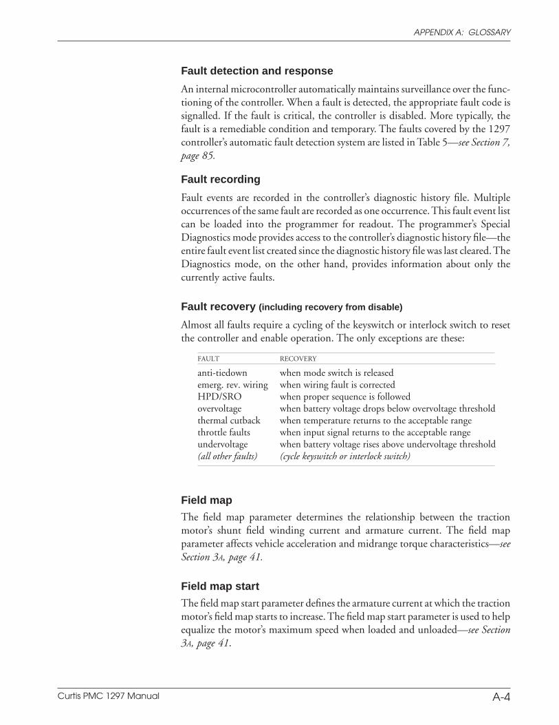
Curtis PMC 1297 Manual A-4
APPENDIX A: GLOSSARY
Fault detection and response
An internal microcontroller automatically maintains surveillance over the func-tioning of the controller. When a fault is detected, the appropriate fault code issignalled. If the fault is critical, the controller is disabled. More typically, thefault is a remediable condition and temporary. The faults covered by the 1297controller’s automatic fault detection system are listed in Table 5—see Section 7,page 85.
Fault recording
Fault events are recorded in the controller’s diagnostic history file. Multipleoccurrences of the same fault are recorded as one occurrence. This fault event listcan be loaded into the programmer for readout. The programmer’s SpecialDiagnostics mode provides access to the controller’s diagnostic history file—theentire fault event list created since the diagnostic history file was last cleared. TheDiagnostics mode, on the other hand, provides information about only thecurrently active faults.
Fault recovery (including recovery from disable)
Almost all faults require a cycling of the keyswitch or interlock switch to resetthe controller and enable operation. The only exceptions are these:
FAULT RECOVERY
anti-tiedown when mode switch is releasedemerg. rev. wiring when wiring fault is correctedHPD/SRO when proper sequence is followedovervoltage when battery voltage drops below overvoltage thresholdthermal cutback when temperature returns to the acceptable rangethrottle faults when input signal returns to the acceptable rangeundervoltage when battery voltage rises above undervoltage threshold(all other faults) (cycle keyswitch or interlock switch)
Field map
The field map parameter determines the relationship between the tractionmotor’s shunt field winding current and armature current. The field mapparameter affects vehicle acceleration and midrange torque characteristics—seeSection 3A, page 41.
Field map start
The field map start parameter defines the armature current at which the tractionmotor’s field map starts to increase. The field map start parameter is used to helpequalize the motor’s maximum speed when loaded and unloaded—see Section3A, page 41.
Curtis PMC 1297 Manual A-5
APPENDIX A: GLOSSARY
Field current values
The maximum and minimum field current limit values have a powerfulinfluence on the vehicle’s maximum speed and torque—see Section 3A, page 41.Tuning the maximum and minimum field current limits is described in detailin Section 5: Vehicle Performance Adjustment.
Full bridge
The 1297 controller uses a full bridge design for control of the traction motor’sfield winding. This eliminates the need for external direction contactors. Theresult is a higher reliability product that is smaller and simpler to install.
Half bridge
The 1297 controller uses a half bridge topology for the traction motor’sarmature drive. This provides reliable and highly efficient vehicle control withfull all-electronic regenerative braking to zero speed.
High-pedal-disable (HPD)
The HPD feature prevents the vehicle from driving if the controller is turnedon when greater than 25% throttle is applied—see Section 3A, page 44.
Hourmeters
The 1297 has three built-in hourmeters: the total hourmeter (measuring KSI-on hours), the traction motor hourmeter (measuring drive hours), and thepump motor hourmeter (measuring pump hours)—see Section 3C, page 59.
Hydraulic inhibit
The hydraulic inhibit feature prevents Lift or Lower operation if the hydraulicthrottle request is greater than 25% when the interlock switch is closed—seeSection 3B, page 48.
Interlock braking
If the interlock switch is opened while the vehicle is being driven, the 1297controller sends braking current to the motor—see Section 3A, page 27.
Interlock switch
The interlock switch is a controller-enable input intended to provide a second-ary operational interlock for the controller in addition to the keyswitch input.If an interlock switch is used, it must be closed in order for the controller tooperate. This safety interlock is used on most material handling vehicles,typically in the form of a tiller switch, deadman footswitch, or seatswitch.

Curtis PMC 1297 Manual A-6
APPENDIX A: GLOSSARY
Cycling the interlock switch or the keyswitch clears most faults and re-enablesoperation.
KSI
KSI (Key Switch Input) provides power to the controller’s logic board, initializesthe microprocessor, and starts diagnostics. In combination with the interlockswitch input, KSI enables all logic functions.
Lift lockout features
Lift operation can be prevented when the pump motor current is too high, whenthe battery state-of-charge is below 20%, or when more than 25% throttle isrequested at the time the interlock switch is closed—see Section 3B, page 48.
Load compensation
The load compensation feature adjusts the applied motor voltage as a functionof motor load current. Load compensation results in more constant vehiclespeeds over variations in motor loading due to ramps and cargo weights, withoutthe operator having to constantly adjust the throttle position—see Section 3A,page 32.
Lowering valve
The aperture of the hydraulic line’s lowering valve determines the speed ofLower operation; the lowering valve can be either a proportional valve or asimple open/closed valve—see Section 3B, page 49.
M- fault detection
This feature determines if the M- power connection is being held low (to B-) byan internal or external fault condition. If an M- fault is detected at the tractionmotor or pump motor M- power connection, the controller will inhibit PWMoutput and release the main contactor. External M- fault detection is notperformed if greater than 50% throttle is being requested. No M- fault detectionis performed if emergency reverse is activated.
MOSFET
A MOSFET (metal oxide semiconductor field effect transistor) is a type oftransistor characterized by its fast switching speeds and very low losses.
MultiMode™
The MultiMode™ feature of the 1297 controller allows the vehicle to beoperated with two distinct sets of characteristics. Typically, Mode 1 is pro-grammed for slow precise indoor maneuvering and Mode 2 for faster, long
Curtis PMC 1297 Manual A-7
APPENDIX A: GLOSSARY
distance, outdoor travel. The following six parameters can be set independentlyin the two modes:
— acceleration rate— braking current limit— braking rate— deceleration rate— drive current limit— maximum speed.
The operator uses the mode switch to select Mode 1 (switch open) or Mode 2(switch closed).
Multiplexer (MUX)
The Curtis PMC 1312 tiller multiplexer provides a 4-wire serial interface for alltiller functions. The typical wiring configuration for applications using themultiplexer is shown in Figure 4, page 10.
OEM (= Original Equipment Manufacturer)
Overtemperature
Because of their efficiency and thermal design, Curtis PMC controllers shouldbarely get warm in normal operation. Overheating can occur, however, if thecontroller is undersized for its application or otherwise overloaded. The 1297controller constantly monitors its internal heatsink temperature. Starting at85°C, the armature current is linearly decreased from full set current down tozero at 95°C. NOTE: Braking current limits are not reduced in overtemperature;this ensures that full vehicle braking is available under all thermal conditions.
Full current and performance return automatically after the controllercools down. Although occasional overtemperature operation is usually notdamaging to the controller, it does suggest a mismatch. If thermal cutbackoccurs often in normal operation, the controller is probably undersized for theapplication and a higher current model should be used. Continuous operationin overtemperature will overstress the power components and reduce thelifetime and reliability of the controller.
Overvoltage protection
The overvoltage protection feature protects the controller if the voltage exceedsthe factory-set limit. Overvoltage can result during battery charging or from animproperly wired controller. As soon as the voltage rises above the overvoltagethreshold, the armature current is cut back linearly until it reaches zero at thecutoff point; normal controller operation resumes when the voltage drops belowthe threshold.
Curtis PMC 1297 Manual A-8
APPENDIX A: GLOSSARY
PWM
Pulse width modulation (PWM), also called “chopping,” is a technique thatswitches battery voltage to the motor on and off very quickly, thereby control-ling the speed of the motor. Curtis PMC 1200 series controllers use highfrequency PWM—in this case, 16 kHz—which permits silent, efficient opera-tion.
Regenerative braking
The 1297 controller uses regenerative braking to slow the vehicle to a stop andto reduce speed when traveling downhill. Regenerative braking means that theenergy used to slow the vehicle is channeled back into the batteries, resulting inlonger vehicle range between charges.
Reset
Some faults require a cycling of the KSI or interlock switch input to reset thecontroller and enable operation; see Fault recovery for exceptions.
Restraint
When the vehicle speed exceeds the requested throttle, the restraint featurecauses the motor to apply a braking force and “restrain” the vehicle to therequested speed—see Section 3, page 27.
Reverse polarity protection
The 1297 controller is protected against reverse polarity by an internal diode.If the battery’s B+ and B- connections to an otherwise properly wired controllerare reversed, the main contactor will not engage—thus protecting the controllerfrom being damaged.
Safe commutation region
The safe commutation region includes all the combinations of field current andarmature current that allow proper commutation between the traction motor’sbrushes and the armature. If the motor operates outside this region, arcing andsevere heating and brush wear will occur. The motor manufacturer should beable to provide curves defining the safe combinations of field and armaturecurrent. We highly recommend that you obtain these curves and use them whentuning the 1297 controller to a particular motor—see Section 5.
Sequencing delay
The sequencing delay feature allows the interlock switch to be cycled within aset time (the sequencing delay), thus preventing inadvertent activation ofvarious lockout features—see Section 3C, page 57.

Curtis PMC 1297 Manual A-9
APPENDIX A: GLOSSARY
Smooth, stepless operation
Like all Curtis PMC 1200 Series controllers, the 1297 allows superior operatorcontrol of the vehicle’s drive motor speed. The amount of current delivered tothe motor is set by varying the “on” time (duty cycle) of the controller’s powerMOSFET transistors. This technique—pulse width modulation (PWM)—permits silent, stepless operation.
Speed limiting
The maximum traction motor speed can be limited in two ways: through themaximum speed parameter (see Section 3A, page 31) and through the minimumfield current limit parameter (see Section 3A, page 41). The latter (Field Min) isthe primary means of adjusting vehicle top speed.
The maximum pump motor speed can be limited through the maximumpump speed parameter (see Section 3B, page 46).
Spyglass display
The Curtis 840 Spyglass display sequences between hourmeter, BDI, and faultcode messages—see Section 2, page 19.
Static-return-to-off (SRO)
The programmable SRO feature prevents the vehicle from being started when“in gear” (i.e., with a direction already selected)—see Section 3A, page 45.
Status LED
A built-in Status LED (Light Emitting Diode) is visible through the labellocated on top of the 1297 controller. The Status LED flashes a 2-digit faultidentification code when a fault is detected by the controller. The fault codecontinues to flash until the fault has been corrected and the fault condition hasbeen cleared. Clearing the fault condition typically requires cycling KSI forfaults detected during startup, and cycling the interlock switch for faultsdetected during operation. The fault codes are defined in Table 6—see Section7, page 87.
Taper rate
The taper rate determines how quickly the vehicle changes direction when theopposite direction is selected—see Section 3A, page 26.
Temperature compensation for current limits
Full temperature compensation provides constant current limits throughout thenormal operating range (heatsink temperatures of -25°C to +85°C). Thetemperature sensor that regulates the current limits is also used to calculate theheatsink temperature displayed by the programmer.
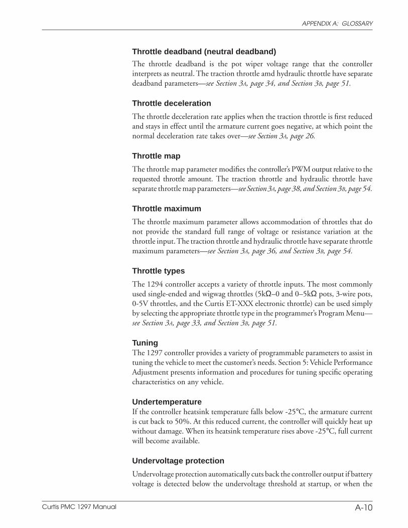
Curtis PMC 1297 Manual A-10
APPENDIX A: GLOSSARY
Throttle deadband (neutral deadband)
The throttle deadband is the pot wiper voltage range that the controllerinterprets as neutral. The traction throttle amd hydraulic throttle have separatedeadband parameters—see Section 3A, page 34, and Section 3B, page 51.
Throttle deceleration
The throttle deceleration rate applies when the traction throttle is first reducedand stays in effect until the armature current goes negative, at which point thenormal deceleration rate takes over—see Section 3A, page 26.
Throttle map
The throttle map parameter modifies the controller’s PWM output relative to therequested throttle amount. The traction throttle and hydraulic throttle haveseparate throttle map parameters—see Section 3A, page 38, and Section 3B, page 54.
Throttle maximum
The throttle maximum parameter allows accommodation of throttles that donot provide the standard full range of voltage or resistance variation at thethrottle input. The traction throttle and hydraulic throttle have separate throttlemaximum parameters—see Section 3A, page 36, and Section 3B, page 54.
Throttle types
The 1294 controller accepts a variety of throttle inputs. The most commonlyused single-ended and wigwag throttles (5kΩ–0 and 0–5kΩ pots, 3-wire pots,0-5V throttles, and the Curtis ET-XXX electronic throttle) can be used simplyby selecting the appropriate throttle type in the programmer’s Program Menu—see Section 3A, page 33, and Section 3B, page 51.
TuningThe 1297 controller provides a variety of programmable parameters to assist intuning the vehicle to meet the customer’s needs. Section 5: Vehicle PerformanceAdjustment presents information and procedures for tuning specific operatingcharacteristics on any vehicle.
UndertemperatureIf the controller heatsink temperature falls below -25°C, the armature currentis cut back to 50%. At this reduced current, the controller will quickly heat upwithout damage. When its heatsink temperature rises above -25°C, full currentwill become available.
Undervoltage protection
Undervoltage protection automatically cuts back the controller output if batteryvoltage is detected below the undervoltage threshold at startup, or when the
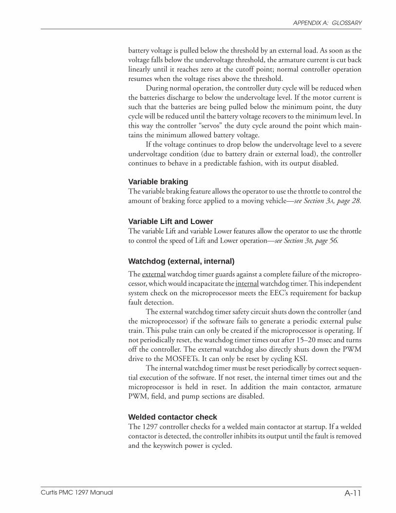
Curtis PMC 1297 Manual A-11
APPENDIX A: GLOSSARY
battery voltage is pulled below the threshold by an external load. As soon as thevoltage falls below the undervoltage threshold, the armature current is cut backlinearly until it reaches zero at the cutoff point; normal controller operationresumes when the voltage rises above the threshold.
During normal operation, the controller duty cycle will be reduced whenthe batteries discharge to below the undervoltage level. If the motor current issuch that the batteries are being pulled below the minimum point, the dutycycle will be reduced until the battery voltage recovers to the minimum level. Inthis way the controller “servos” the duty cycle around the point which main-tains the minimum allowed battery voltage.
If the voltage continues to drop below the undervoltage level to a severeundervoltage condition (due to battery drain or external load), the controllercontinues to behave in a predictable fashion, with its output disabled.
Variable brakingThe variable braking feature allows the operator to use the throttle to control theamount of braking force applied to a moving vehicle—see Section 3A, page 28.
Variable Lift and LowerThe variable Lift and variable Lower features allow the operator to use the throttleto control the speed of Lift and Lower operation—see Section 3B, page 56.
Watchdog (external, internal)
The external watchdog timer guards against a complete failure of the micropro-cessor, which would incapacitate the internal watchdog timer. This independentsystem check on the microprocessor meets the EEC’s requirement for backupfault detection.
The external watchdog timer safety circuit shuts down the controller (andthe microprocessor) if the software fails to generate a periodic external pulsetrain. This pulse train can only be created if the microprocessor is operating. Ifnot periodically reset, the watchdog timer times out after 15–20 msec and turnsoff the controller. The external watchdog also directly shuts down the PWMdrive to the MOSFETs. It can only be reset by cycling KSI.
The internal watchdog timer must be reset periodically by correct sequen-tial execution of the software. If not reset, the internal timer times out and themicroprocessor is held in reset. In addition the main contactor, armaturePWM, field, and pump sections are disabled.
Welded contactor checkThe 1297 controller checks for a welded main contactor at startup. If a weldedcontactor is detected, the controller inhibits its output until the fault is removedand the keyswitch power is cycled.
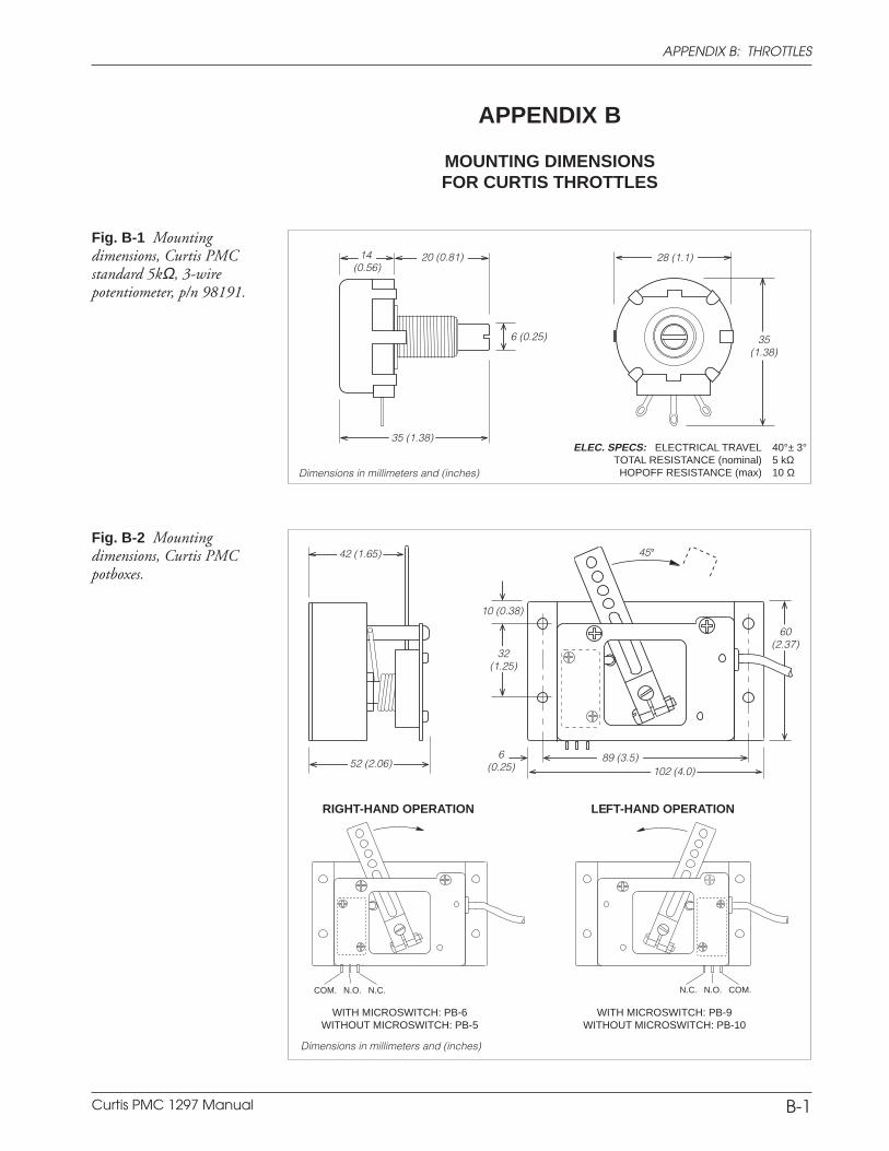
Curtis PMC 1297 Manual A-12
APPENDIX A: GLOSSARY
APPENDIX B
MOUNTING DIMENSIONSFOR CURTIS THROTTLES
Fig. B-1 Mountingdimensions, Curtis PMCstandard 5kΩ, 3-wirepotentiometer, p/n 98191.
10 (0.38)
32(1.25)
6(0.25)
89 (3.5)
60(2.37)
102 (4.0)
45°
Dimensions in millimeters and (inches)
RIGHT-HAND OPERATION LEFT-HAND OPERATION
COM. N.O. N.C. N.C. N.O. COM.
WITH MICROSWITCH: PB-6WITHOUT MICROSWITCH: PB-5
WITH MICROSWITCH: PB-9WITHOUT MICROSWITCH: PB-10
42 (1.65)
52 (2.06)
Fig. B-2 Mountingdimensions, Curtis PMCpotboxes.
14 (0.56)
20 (0.81)
35 (1.38)
6 (0.25) 35(1.38)
28 (1.1)
Dimensions in millimeters and (inches)
ELEC. SPECS: ELECTRICAL TRAVEL 40°± 3°TOTAL RESISTANCE (nominal) 5 kΩHOPOFF RESISTANCE (max) 10 Ω
B-1
APPENDIX B: THROTTLES
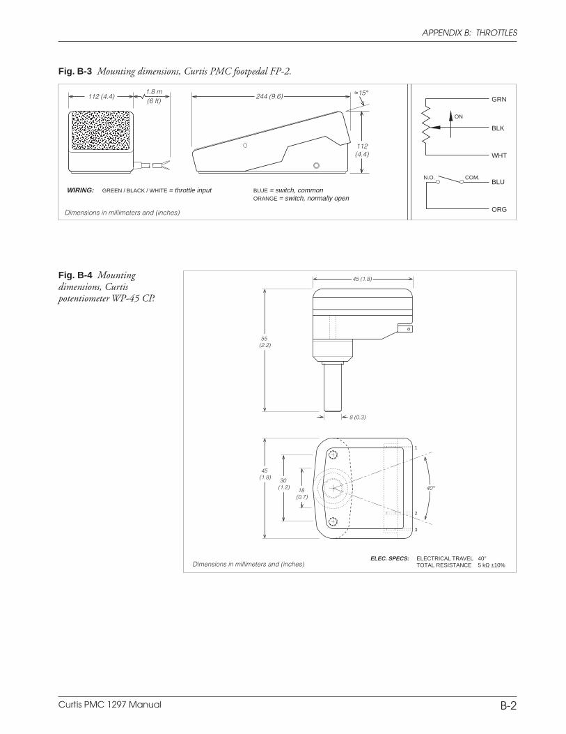
Curtis PMC 1297 Manual A-13
APPENDIX A: GLOSSARY
B-2
Fig. B-4 Mountingdimensions, Curtispotentiometer WP-45 CP.
APPENDIX B: THROTTLES
40°18 (0.7)
45 (1.8) 30
(1.2)
45 (1.8)
Dimensions in millimeters and (inches)
55 (2.2)
ELEC. SPECS: ELECTRICAL TRAVEL 40°TOTAL RESISTANCE 5 kΩ ±10%
8 (0.3)
1
2
3
Fig. B-3 Mounting dimensions, Curtis PMC footpedal FP-2.
Dimensions in millimeters and (inches)
≈15°244 (9.6)112 (4.4)
112(4.4)
1.8 m(6 ft)
WIRING: GREEN / BLACK / WHITE = throttle input BLUE = switch, commonORANGE = switch, normally open
BLK
ON
GRN
WHT
ORG
BLUCOM.N.O.
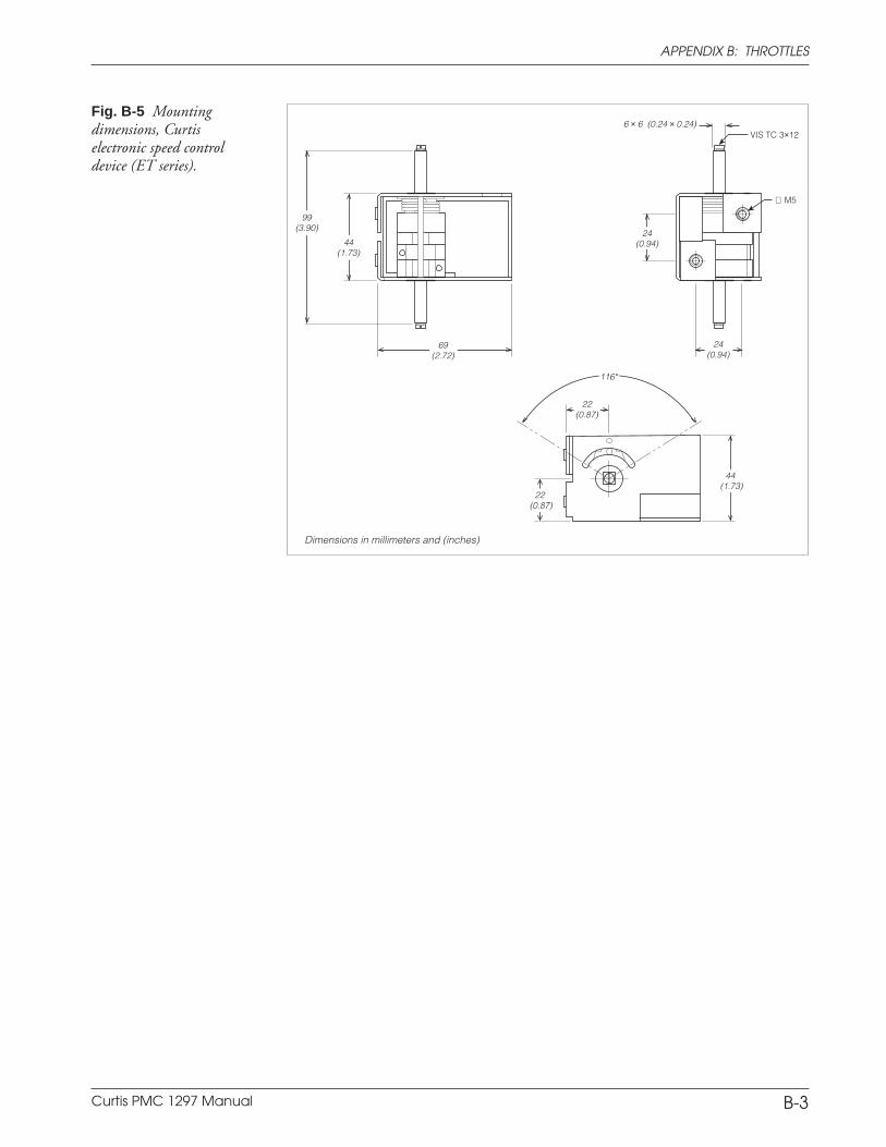
Curtis PMC 1297 Manual A-14
APPENDIX A: GLOSSARY
B-3
APPENDIX B: THROTTLES
Fig. B-5 Mountingdimensions, Curtiselectronic speed controldevice (ET series).
Dimensions in millimeters and (inches)
99(3.90)
44(1.73)
69(2.72)
24(0.94)
VIS TC 3×126 × 6 (0.24 × 0.24)
24(0.94)
∅ M5
22(0.87)
22 (0.87)
116°
44 (1.73)
Curtis PMC 1297 Manual A-15
APPENDIX A: GLOSSARY
C-1
APPENDIX C
VEHICLE DESIGN CONSIDERATIONS
REGARDING ELECTROMAGNETIC COMPATIBILITY (EMC)
AND ELECTROSTATIC DISCHARGE (ESD)
ELECTROMAGNETIC COMPATIBILITY (EMC)
Electromagnetic compatibility (EMC) encompasses two areas: emissions andimmunity. Emissions are radio frequency (rf ) energy generated by a product.This energy has the potential to interfere with communications systems such asradio, television, cellular phones, dispatching, aircraft, etc. Immunity is theability of a product to operate normally in the presence of rf energy.
EMC is ultimately a system design issue. Part of the EMC performanceis designed into or inherent in each component; another part is designed intoor inherent in end product characteristics such as shielding, wiring, and layout;and, finally, a portion is a function of the interactions between all these parts.The design techniques presented below can enhance EMC performance inproducts that use Curtis PMC motor controllers.
Decreasing Emissions
Motor brush arcing can be a significant source of rf emissions. These emissionsmay be reduced by installing bypass capacitors across the motor wires and/orbetween each motor wire and the motor frame. If the latter approach is used, thevoltage rating and leakage characteristics of the capacitors must be adequate tomeet any safety regulations regarding electrical connections between a batteryoperated circuit and the chassis. The bypass capacitor should be installed as closeto the motor as possible, or even inside it, to provide the best performance.Alternatively a ferrite bead can be installed on the wires, as close as possible tothe motor. In some instances, capacitors and ferrite beads may both be appro-priate. Another option is to choose a motor with a brush material that will resultin less arcing to the commutator. Brushes that have been run in for approxi-mately 100 hours will typically generate lower emissions than new brushesbecause there is less arcing after they are properly seated.
The motor drive output from Curtis PMC controllers can also make acontribution to rf emissions. This output is a pulse width modulated squarewave with rather fast rise and fall times that are rich in harmonics. The impactof these switching waveforms can be minimized by making the wires from thecontroller to the motor as short as possible. Ferrite beads installed on the drivewires can further reduce these emissions. For applications requiring very lowemissions, the solution may involve enclosing the controller, interconnectwires, and motor together in one shielded box. The motor drive harmonics cancouple to battery supply leads and throttle circuit wires, so ferrite beads mayalso be required on these other wires in some applications.
APPENDIX C: EMC & ESD DESIGN CONSIDERATIONS
Curtis PMC 1297 Manual A-16
APPENDIX A: GLOSSARY
C-2
Increasing Immunity
Immunity to radiated electric fields can be achieved either by reducing theoverall circuit sensitivity or by keeping the undesired signals away from thiscircuitry. The controller circuitry itself cannot be made less sensitive, since itmust accurately detect and process low level signals from the throttle potenti-ometer. Thus immunity is generally achieved by preventing the external rfenergy from coupling into sensitive circuitry. This rf energy can get into thecontroller circuitry via conducted paths and via radiated paths.
Conducted paths are created by the wires connected to the controller.These wires act as antennas and the amount of rf energy coupled into thesewires is generally proportional to their length. The rf voltages and currentsinduced in each wire are applied to the controller pin to which the wire isconnected. Curtis PMC motor controllers include bypass capacitors on theprinted circuit board’s throttle wires to reduce the impact of this rf energy onthe internal circuitry. In some applications, ferrite beads may also be requiredon the various wires to achieve desired performance levels.
Radiated paths are created when the controller circuitry is immersed in anexternal field. This coupling can be reduced by enclosing the controller in ametal box. Some Curtis PMC motor controllers are enclosed by a heat sink thatalso provides shielding around the controller circuitry, while others are unshielded.In some applications, the vehicle designer will need to mount the controllerwithin a shielded box on the end product. The box may be constructed of justabout any metal, although steel and aluminum are most commonly used.
Most coated plastics do not provide good shielding because the coatingsare not true metals, but rather a mixture of small metal particles in a non-conductive binder. These relatively isolated particles may appear to be goodbased on a dc resistance measurement but do not provide adequate electronmobility to yield good shielding effectiveness. Electroless plating of plastic willyield a true metal and can thus be effective as an rf shield, but it is usually moreexpensive than the coatings.
A contiguous metal enclosure without any holes or seams, known as aFaraday cage, provides the best shielding for the given material and frequency.When a hole or holes are added, rf currents flowing on the outside surface of theshield must take a longer path to get around the hole than if the surface wascontiguous. As more “bending” is required of these currents, more energy iscoupled to the inside surface, and thus the shielding effectiveness is reduced.The reduction in shielding is a function of the longest linear dimension of ahole rather than the area. This concept is often applied where ventilation isnecessary, in which case many small holes are preferable to a few larger ones.
Applying this same concept to seams or joints between adjacent pieces orsegments of a shielded enclosure, it is important to minimize the open lengthof these seams. Seam length is the distance between points where good ohmiccontact is made. This contact can be provided by solder, welds, or pressurecontact. If pressure contact is used, attention must be paid to the corrosioncharacteristics of the shield material and any corrosion-resistant processes
APPENDIX C: EMC & ESD DESIGN CONSIDERATIONS
Curtis PMC 1297 Manual A-17
APPENDIX A: GLOSSARY
C-3
applied to the base material. If the ohmic contact itself is not continuous, theshielding effectiveness can be maximized by making the joints between adjacentpieces overlapping rather than abutted.
The shielding effectiveness of an enclosure is further reduced when a wirepasses through a hole in the enclosure. RF energy on the wire from an externalfield is re-radiated into the interior of the enclosure. This coupling mechanismcan be reduced by filtering the wire at the point where it passes through theboundary of the shield. Given the safety considerations involved with connect-ing electrical components to the chassis or frame in battery powered vehicles,such filtering will usually consist of a series inductor (or ferrite bead) rather thana shunt capacitor. If a capacitor is used, it must have a voltage rating and leakagecharacteristics that will allow the end product to meet applicable safety regula-tions.
The B+ (and B-, if applicable) wires that supply power to the throttlecontrol panel—such as for the keyswitch—should be bundled with the remain-ing throttle wires so that all these wires are routed together. If the wires to thecontrol panel are routed separately, a larger loop area is formed. Larger loopareas produce more efficient antennas which will result in decreased immunityperformance.
ELECTROSTATIC DISCHARGE (ESD)
Curtis PMC motor controllers contain ESD-sensitive components, and it istherefore necessary to protect them from ESD damage. Electrostatic discharge(ESD) immunity is achieved either by providing sufficient distance betweenconductors and the outside world so that a discharge will not occur, or byproviding an intentional path for the discharge current such that the circuit isisolated from the electric and magnetic fields produced by the discharge. Ingeneral the guidelines presented above for increasing the radiated immunity willalso provide increased ESD immunity.
It is usually easier to prevent the discharge from occurring than to divertthe current path. A fundamental technique for ESD prevention is to provideadequately thick insulation between all metal conductors and the outsideenvironment so that the voltage gradient does not exceed the threshold requiredfor a discharge to occur. If the current diversion approach is used, all exposedmetal components must be grounded. The shielded enclosure, if properlygrounded, can be used to divert the discharge current; it should be noted thatthe location of holes and seams can have a significant impact on the ESDsuppression. If the enclosure is not grounded, the path of the discharge currentbecomes more complex and less predictable, especially if holes and seams areinvolved. Some experimentation may be required to optimize the selection andplacement of holes, wires, and grounding paths. Careful attention must be paidto the control panel design so that it can tolerate a static discharge.
APPENDIX C: EMC & ESD DESIGN CONSIDERATIONS
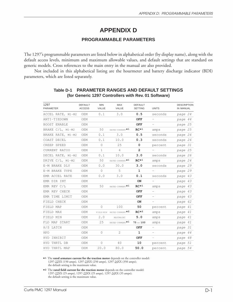
Curtis PMC 1297 Manual A-18
APPENDIX A: GLOSSARY
APPENDIX DPROGRAMMABLE PARAMETERS
The 1297’s programmable parameters are listed below in alphabetical order (by display name), along with thedefault access levels, minimum and maximum allowable values, and default settings that are standard ongeneric models. Cross references to the main entry in the manual are also provided.
Not included in this alphabetical listing are the hourmeter and battery discharge indicator (BDI)parameters, which are listed separately.
Table D-1 PARAMETER RANGES AND DEFAULT SETTINGS(for Generic 1297 Controllers with Rev. 01 Software)
1297 DEFAULT MIN MAX DEFAULT DESCRIPTIONPARAMETER ACCESS VALUE VALUE SETTING UNITS IN MANUAL
ACCEL RATE, M1-M2 OEM 0.1 3.0 0.5 seconds page 24
ANTI-TIEDOWN OEM OFF — page 44
BOOST ENABLE OEM OFF — page 25
BRAKE C/L, M1-M2 OEM 50 RATED CURRENT*1 RC*1 amps page 25
BRAKE RATE, M1-M2 OEM 0.1 3.0 0.5 seconds page 26
COAST DECEL OEM 0.1 10.0 0.3 seconds page 26
CREEP SPEED OEM 0 25 0 percent page 31
CURRENT RATIO OEM 1 4 2 — page 25
DECEL RATE, M1-M2 OEM 0.1 10.0 3.0 seconds page 26
DRIVE C/L, M1-M2 OEM 50 RATED CURRENT*1 RC*1 amps page 24
E-M BRAKE DLY OEM 0.0 30.0 3.0 seconds page 29
E-M BRAKE TYPE OEM 0 5 1 — page 29
EMR ACCEL RATE OEM 0.0 3.0 0.1 seconds page 43
EMR DIR INT OEM ON — page 43
EMR REV C/L OEM 50 RATED CURRENT*1 RC*1 amps page 43
EMR REV CHECK OEM OFF — page 43
EMR TIME LIMIT OEM OFF — page 43
FIELD CHECK OEM ON — page 42
FIELD MAP OEM 0 100 50 percent page 41
FIELD MAX OEM FIELD MIN RATED CURRENT*2 RC*2 amps page 41
FIELD MIN OEM 2.0 RESTRAINT 5.0 amps page 41
FLD MAP START OEM 25 RATED CURRENT*1 75 or 100 amps page 41
H/S LATCH OEM OFF — page 31
HPD OEM 0 2 1 — page 44
HYD INHIBIT OEM OFF — page 48
HYD THRTL DB OEM 0 40 10 percent page 51
HYD THRTL MAP OEM 20.0 80.0 50.0 percent page 54
D-1
APPENDIX D: PROGRAMMABLE PARAMETERS
*1 The rated armature current for the traction motor depends on the controller model:1297-22XX (150 amps), 1297-23XX (250 amps), 1297-24XX (350 amps);the default setting is the maximum value.
*2 The rated field current for the traction motor depends on the controller model:1297-22XX (25 amps), 1297-23XX (25 amps), 1297-24XX (35 amps);the default setting is the maximum value.
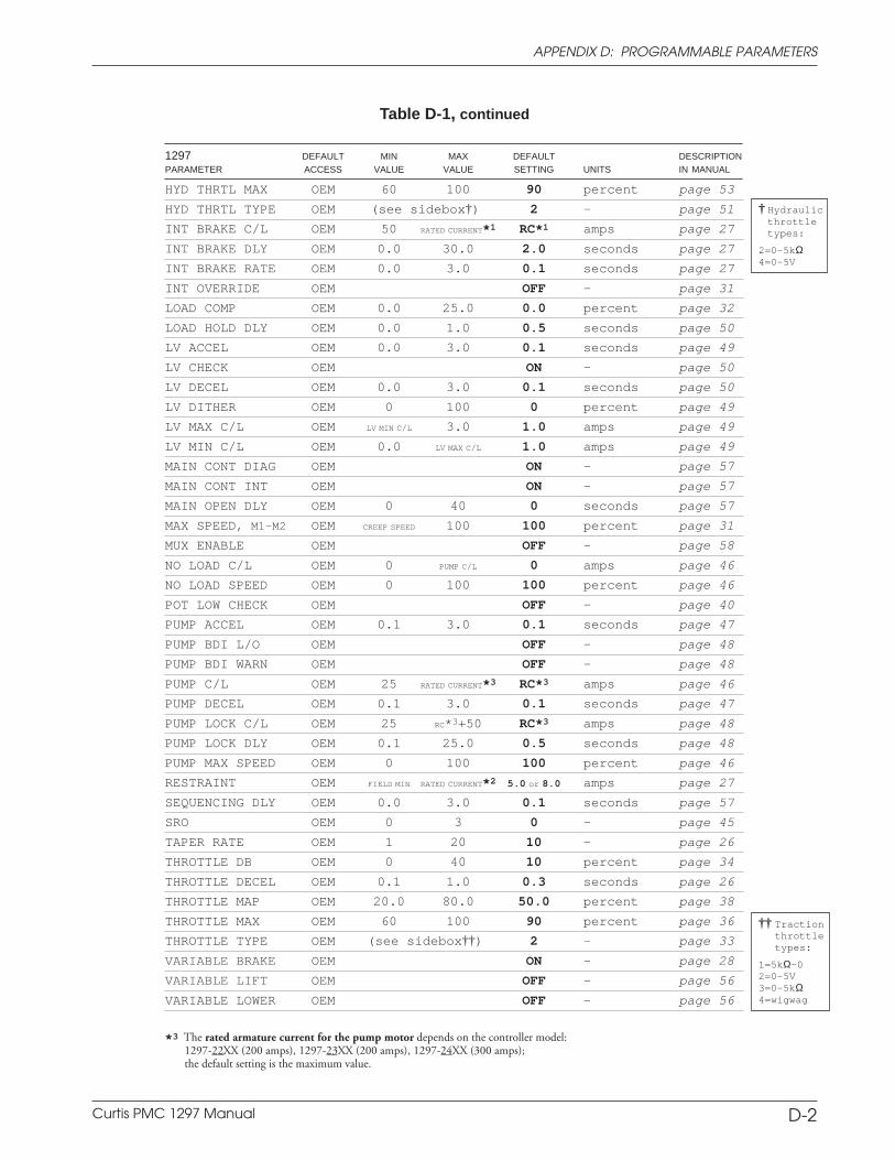
Curtis PMC 1297 Manual A-19
APPENDIX A: GLOSSARY
HYD THRTL MAX OEM 60 100 90 percent page 53
HYD THRTL TYPE OEM (see sidebox†) 2 — page 51
INT BRAKE C/L OEM 50 RATED CURRENT*1 RC*1 amps page 27
INT BRAKE DLY OEM 0.0 30.0 2.0 seconds page 27
INT BRAKE RATE OEM 0.0 3.0 0.1 seconds page 27
INT OVERRIDE OEM OFF — page 31
LOAD COMP OEM 0.0 25.0 0.0 percent page 32
LOAD HOLD DLY OEM 0.0 1.0 0.5 seconds page 50
LV ACCEL OEM 0.0 3.0 0.1 seconds page 49
LV CHECK OEM ON — page 50
LV DECEL OEM 0.0 3.0 0.1 seconds page 50
LV DITHER OEM 0 100 0 percent page 49
LV MAX C/L OEM LV MIN C/L 3.0 1.0 amps page 49
LV MIN C/L OEM 0.0 LV MAX C/L 1.0 amps page 49
MAIN CONT DIAG OEM ON — page 57
MAIN CONT INT OEM ON — page 57
MAIN OPEN DLY OEM 0 40 0 seconds page 57
MAX SPEED, M1-M2 OEM CREEP SPEED 100 100 percent page 31
MUX ENABLE OEM OFF — page 58
NO LOAD C/L OEM 0 PUMP C/L 0 amps page 46
NO LOAD SPEED OEM 0 100 100 percent page 46
POT LOW CHECK OEM OFF — page 40
PUMP ACCEL OEM 0.1 3.0 0.1 seconds page 47
PUMP BDI L/O OEM OFF — page 48
PUMP BDI WARN OEM OFF — page 48
PUMP C/L OEM 25 RATED CURRENT*3 RC*3 amps page 46
PUMP DECEL OEM 0.1 3.0 0.1 seconds page 47
PUMP LOCK C/L OEM 25 RC*3+50 RC*3 amps page 48
PUMP LOCK DLY OEM 0.1 25.0 0.5 seconds page 48
PUMP MAX SPEED OEM 0 100 100 percent page 46
RESTRAINT OEM FIELD MIN RATED CURRENT*2 5.0 or 8.0 amps page 27
SEQUENCING DLY OEM 0.0 3.0 0.1 seconds page 57
SRO OEM 0 3 0 — page 45
TAPER RATE OEM 1 20 10 — page 26
THROTTLE DB OEM 0 40 10 percent page 34
THROTTLE DECEL OEM 0.1 1.0 0.3 seconds page 26
THROTTLE MAP OEM 20.0 80.0 50.0 percent page 38
THROTTLE MAX OEM 60 100 90 percent page 36
THROTTLE TYPE OEM (see sidebox††) 2 — page 33
VARIABLE BRAKE OEM ON — page 28
VARIABLE LIFT OEM OFF — page 56
VARIABLE LOWER OEM OFF — page 56
1297 DEFAULT MIN MAX DEFAULT DESCRIPTIONPARAMETER ACCESS VALUE VALUE SETTING UNITS IN MANUAL
Table D-1, continued
D-2
APPENDIX D: PROGRAMMABLE PARAMETERS
†† Tractionthrottletypes:
1=5kΩ–02=0–5V3=0–5kΩ4=wigwag
† Hydraulicthrottletypes:
2=0–5kΩ4=0-5V
*3 The rated armature current for the pump motor depends on the controller model:1297-22XX (200 amps), 1297-23XX (200 amps), 1297-24XX (300 amps);the default setting is the maximum value.
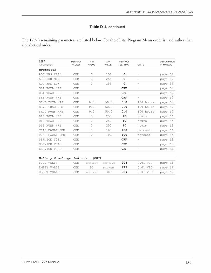
Curtis PMC 1297 Manual A-20
APPENDIX A: GLOSSARY
Hourmeter
ADJ HRS HIGH OEM 0 151 0 — page 59
ADJ HRS MID OEM 0 255 0 — page 59
ADJ HRS LOW OEM 0 255 0 — page 59
SET TOTL HRS OEM OFF — page 60
SET TRAC HRS OEM OFF — page 60
SET PUMP HRS OEM OFF — page 60
SRVC TOTL HRS OEM 0.0 50.0 0.0 100 hours page 60
SRVC TRAC HRS OEM 0.0 50.0 0.0 100 hours page 60
SRVC PUMP HRS OEM 0.0 50.0 0.0 100 hours page 60
DIS TOTL HRS OEM 0 250 10 hours page 61
DIS TRAC HRS OEM 0 250 10 hours page 61
DIS PUMP HRS OEM 0 250 10 hours page 61
TRAC FAULT SPD OEM 0 100 100 percent page 61
PUMP FAULT SPD OEM 0 100 100 percent page 61
SERVICE TOTL OEM OFF — page 62
SERVICE TRAC OEM OFF — page 62
SERVICE PUMP OEM OFF — page 62
Battery Discharge Indicator (BDI)
FULL VOLTS OEM EMPTY VOLTS RESET VOLTS 204 0.01 VPC page 63
EMPTY VOLTS OEM 90 FULL VOLTS 173 0.01 VPC page 63
RESET VOLTS OEM FULL VOLTS 300 209 0.01 VPC page 63
1297 DEFAULT MIN MAX DEFAULT DESCRIPTIONPARAMETER ACCESS VALUE VALUE SETTING UNITS IN MANUAL
Table D-1, continued
The 1297’s remaining parameters are listed below. For these lists, Program Menu order is used rather thanalphabetical order.
APPENDIX D: PROGRAMMABLE PARAMETERS
D-3
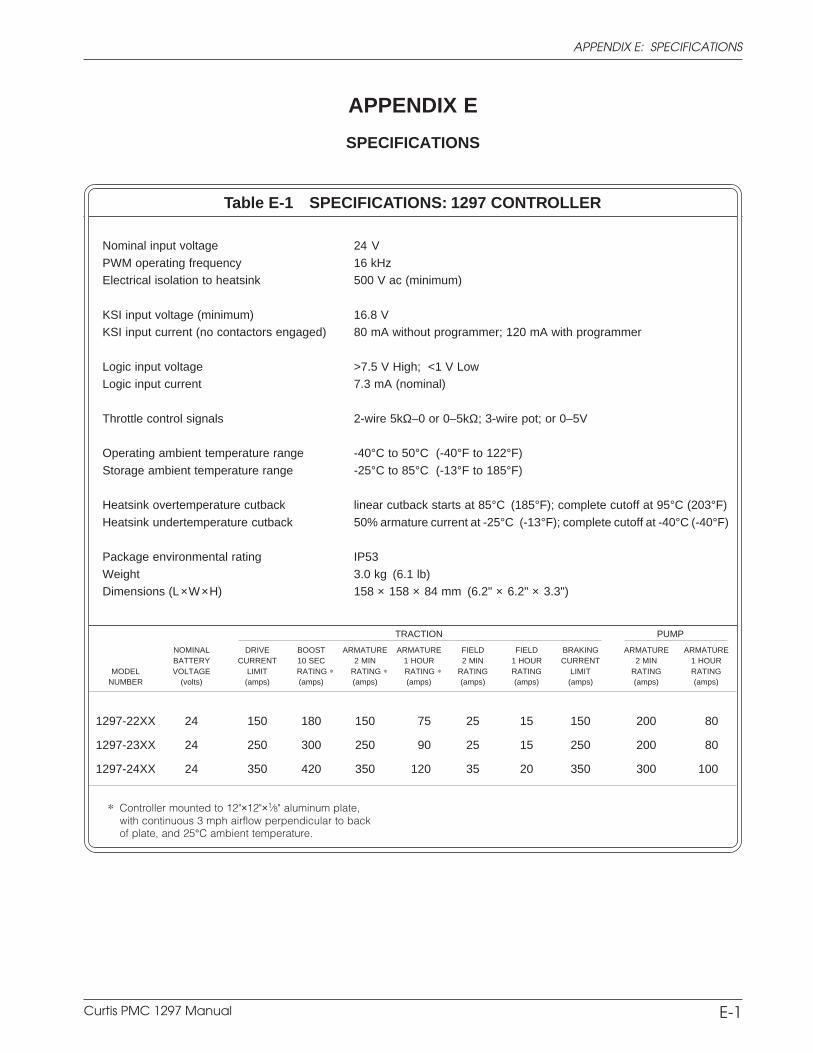
Curtis PMC 1297 Manual A-21
APPENDIX A: GLOSSARY
APPENDIX E
SPECIFICATIONS
TRACTION PUMP
NOMINAL DRIVE BOOST ARMATURE ARMATURE FIELD FIELD BRAKING ARMATURE ARMATUREBATTERY CURRENT 10 SEC 2 MIN 1 HOUR 2 MIN 1 HOUR CURRENT 2 MIN 1 HOUR
MODEL VOLTAGE LIMIT RATING * RATING * RATING * RATING RATING LIMIT RATING RATINGNUMBER (volts) (amps) (amps) (amps) (amps) (amps) (amps) (amps) (amps) (amps)
1297-22XX 24 150 180 150 75 25 15 150 200 80
1297-23XX 24 250 300 250 90 25 15 250 200 80
1297-24XX 24 350 420 350 120 35 20 350 300 100
* Controller mounted to 12"×12"×1⁄8" aluminum plate,with continuous 3 mph airflow perpendicular to backof plate, and 25°C ambient temperature.
Table E-1 SPECIFICATIONS: 1297 CONTROLLER
Nominal input voltage 24 V
PWM operating frequency 16 kHzElectrical isolation to heatsink 500 V ac (minimum)
KSI input voltage (minimum) 16.8 VKSI input current (no contactors engaged) 80 mA without programmer; 120 mA with programmer
Logic input voltage >7.5 V High; <1 V LowLogic input current 7.3 mA (nominal)
Throttle control signals 2-wire 5kΩ–0 or 0–5kΩ; 3-wire pot; or 0–5V
Operating ambient temperature range -40°C to 50°C (-40°F to 122°F)
Storage ambient temperature range -25°C to 85°C (-13°F to 185°F)
Heatsink overtemperature cutback linear cutback starts at 85°C (185°F); complete cutoff at 95°C (203°F)
Heatsink undertemperature cutback 50% armature current at -25°C (-13°F); complete cutoff at -40°C (-40°F)
Package environmental rating IP53
Weight 3.0 kg (6.1 lb)Dimensions (L×W×H) 158 × 158 × 84 mm (6.2" × 6.2" × 3.3")
APPENDIX E: SPECIFICATIONS
E-1