Embed Size (px)
Citation preview
LaboPol-1 LaboPol-2 LaboPol-4 LaboPol-5 LaboPol-6 Instruction Manual Gebrauchsanweisung Mode d’emploi Spare Parts and Diagrams
Manual No.: 15207001
Date of Release 13.09.2013

LaboPol-1/-2/-4/-5/-6 Instruction Manual
Instruction Manual
Always state Serial No and Voltage/frequency if you have technical questions or when ordering spare parts. You will find the Serial No. and Voltage on the type plate of the machine itself. We may also need the Date and Article No of the manual. This information is found on the front cover. The following restrictions should be observed, as violation of the restrictions may cause cancellation of Struers legal obligations: Instruction Manuals: Struers Instruction Manual may only be used in connection with Struers equipment covered by the Instruction Manual. Service Manuals: Struers Service Manual may only be used by a trained technician authorised by Struers. The Service Manual may only be used in connection with Struers equipment covered by the Service Manual. Struers assumes no responsibility for errors in the manual text/illustrations. The information in this manual is subject to changes without notice. The manual may mention accessories or parts not included in the present version of the equipment. Original instructions. The contents of this manual is the property of Struers. Reproduction of any part of this manual without the written permission of Struers is not allowed. All rights reserved. © Struers 2013. Struers A/S Pederstrupvej 84 DK-2750 BallerupDenmark Telephone +45 44 600 800 Fax +45 44 600 801

LaboPol-1/-2/-4/-5/-6 Instruction Manual
LaboPol Safety Precaution Sheet
To be read carefully before use 1. The operator(s) should be fully aware of the use of the machine
according to the Instruction Manual.
2. The machine must be placed in an adequate working position.
3. Be sure that the actual voltage corresponds to the voltage stated on the back of the machine. The machine must be earthed.
4. Be sure that the water connections are without leaks.
5. Struers recommend that the mains water supply is shut off or disconnected if the machine is to be left unattended.
6. When using MD-Disc and MD-Consumables the machine must not be used at speeds higher than 600 rpm.
7. If you observe malfunctions or hear unusual noises - stop the machine and call technical service.
8. The machine must be disconnected from the mains prior to any service. Wait until residual potential on the capacitors is discharged.
9. Do not cycle mains power more than once every three minutes. Damage to the drive will result.
The equipment should only be used for its intended purpose and as detailed in the Instruction Manual. The equipment is designed for use with consumables supplied by Struers. If subjected to misuse, improper installation, alteration, neglect, accident or improper repair, Struers will accept no responsibility for damage(s) to the user or the equipment. Dismantling of any part of the equipment, during service or repair, should always be performed by a qualified technician (electromechanical, electronic, mechanical, pneumatic, etc.).

LaboPol-1/-2/-4/-5/-6 Instruction Manual
Disposal Equipment marked with a WEEE symbol contain electrical and electronic components and must not be disposed of as general waste. Please contact your local authorities for information on the correct method of disposal in accordance with national legislation.
LaboPol-1/-2/-4/-5/-6 Instruction Manual
1
User’s Guide Table of Contents Page
1. Getting Started Checking the Contents of Packing ..................................................... 2 Placing LaboPol ................................................................................. 2 Back View of LaboPol ........................................................................ 2 Supplying Power ................................................................................ 3
Single-phase Supply ................................................................. 3 2-phase Supply ......................................................................... 3 Connection to the Machine ....................................................... 3
Supplying Water ................................................................................. 4 Water Outlet .............................................................................. 4 Water Inlet ................................................................................. 4
2. Operation Getting Acquainted with LaboPol ....................................................... 5 Mounting a Disc ................................................................................. 6 Starting the Machine .......................................................................... 6 Stopping the Machine ........................................................................ 6

LaboPol-1/-2/-4/-5/-6 Instruction Manual
2
1. Getting Started In the packing box you should find the following parts: 1 LaboPol-1/-2/-4/-5 or -6, complete with inlet hose 1 or 2 Mains cables (depending on voltage version) 1 Disposable bowl liner (clear plastic) 1 Splash ring 1 Outlet hose 1 Hose clamp ø 25-40 mm 1 Reduction ring 1 Union nut 1 Gasket 1 Hose clamp 1 Instruction Manual Set The LaboPol machines should be placed on a steady table with an adequate working height. The machines must be placed close to the power supply, water mains and water outlet facilities.
Fuse 4 AT
Specimen mover Probenhalter Porte chantillon-è
On
Off
Water inlet Water outlet On/off switch for specimen mover Power supply socket for specimen mover Communication socket for specimen mover Fuse Main switch Power inlet
Checking the Contents of Packing
Placing LaboPol
Back View of LaboPol

LaboPol-1/-2/-4/-5/-6 Instruction Manual
3
Always remember to switch the power off when installing electrical equipment.
The LaboPol is shipped with 2 types of Mains cables: The 2-pin (European Schuko) plug is for use on single-phase connections. If the plug supplied on this cable is not approved in your country, then the plug must be replaced with an approved plug. The leads must be connected as follows: Yellow/green: earth Brown: line (live) Blue: neutral The 3-pin (North American NEMA) plug is for use on 2-phase power connections. If the plug supplied on this cable is not approved in your country, then the plug must be replaced with an approved plug. The leads must be connected as follows: Green: earth Black: line (live) White: line (live) Both cables are on the other end equipped with an IEC 320 cable connector that has to be connected to the LaboPol.
Supplying Power
IMPORTANT Check that the mains voltage corresponds to the voltage stated
on the type plate on the back of the machine.
Single-phase Supply
2-phase Supply
Connection to the Machine
WARNING! The output voltage from this cable is 200 – 240V and not 110V.
DO NOT use this cable to connect equipment that use an 110V power supply. Failure to adhere to this may result in material damage.
DANGER!
The machine must be earthed
IMPORTANT If no specimen mover is connected to the LaboPol machine,
remember to set the switch “specimen mover” into the off position. Otherwise the LaboPol can not be started.

LaboPol-1/-2/-4/-5/-6 Instruction Manual
4
Connect the outlet hose to the water outlet on the back of the machine and secure the hose using the hose clamp. Lead the other end of the outlet hose to the drain. Be absolutely sure to place the outlet hose with a steady slope to prevent the water from being discharged too slowly, which may cause overflow or blocking the water outlet. Please avoid sharp bends on the outlet hose. Connect the inlet hose to the water tap and secure with a hose clamp. The fittings (gasket, union nut and reduction ring) supplied with the machine may also be used for the connection.
Supplying Water Water Outlet
Water Inlet

LaboPol-1/-2/-4/-5/-6 Instruction Manual
5
2. Operation Take a moment to familiarise yourself with the location and names of the LaboPol components.
LaboPol-1 with LaboForce-3
LaboPol-2 with LaboForce-3
Start switch Stop switch Turntable Water tap
Start switch 250 rpm Start switch 500 rpm Stop switch Turntable Water tap
Getting Acquainted with LaboPol

LaboPol-1/-2/-4/-5/-6 Instruction Manual
6
LaboPol-4/-5/-6 with LaboForce-3
Start switch Stop switch Speed control Turntable Water tap Place the preparation disc on the turntable and turn it until the three pins of the preparation disc engage with the holes in the turntable. Press the start switch. The machine starts operating Press the 250 rpm or 500 rpm start switch. Set the speed control to the desired speed. Press the start switch. The machine starts operating Press the stop switch.
Mounting a Disc
Starting the Machine LaboPol-1
LaboPol-2
LaboPol-4/-5 /-6
Stopping the Machine

LaboPol-1/-2/-4/-5/-6 Instruction Manual
7
Reference Guide Table of Contents Page
1. Advanced Operations Selection of Disc ................................................................................ 8 Mounting of Specimen Mover (Optional) ............................................ 8
2. Struers Metalog Guide™ ...................................................... 9
3. Accessories and Connected Equipment ......................... 10
4. Trouble-Shooting .................................................................. 11
5. Maintenance Daily Service .................................................................................... 12 Weekly Service ................................................................................ 12
6. Technical Data ...................................................................... 13

LaboPol-1/-2/-4/-5/-6 Instruction Manual
8
1. Advanced Operations LaboPol is designed for use with wet grinding and polishing discs. The diameter of wet grinding discs with ring should be 230 mm. When using polishing cloths, MD-Piano, MD-Primo, MD-Allegro, MD-Largo or SiC-paper / SiC-Foil, discs with 200 mm dia. must be used. LaboPol can be equipped with either LaboForce-3 or LaboForce-1 specimen mover.
Selection of Disc
Mounting of Specimen Mover (Optional)
Please Note To mount the specimen mover, see the LaboForce Instruction Manual.

LaboPol-1/-2/-4/-5/-6 Instruction Manual
9
2. Struers Metalog Guide™ LaboPol is designed for preparation of most materials. In Struers Metalog Guide™ you will find a detailed description of grinding/polishing methods for automated mechanical specimen preparation. Struers Metalog Guide™ offers preparation methods for the most common materials, based on a simple analysis of two key properties: hardness and ductility. Finding the right method is easy, including choice of consumables. Always consult Struers Metalog Guide™ on the Struers website for the correct preparation method for the actual specimens.
Metalog Guide™ A complete guide to materialographic specimen preparation.
www.struers.com/KNOWLEDGE/Metalog Guide.

LaboPol-1/-2/-4/-5/-6 Instruction Manual
10
3. Accessories and Connected Equipment Specification Cat. No: Wet Grinding Disc with Ring 230 mm dia., Aluminium
02426936
Polishing Discs 200 mm dia., aluminium
03756902
Disc for Magnetic Fixation MD-Disc, 200 mm dia.
02426920
Disposable bowl liner, 5 pcs 49900041 Specification Cat. No: LaboForce-3, specimen mover 1 x 100-120 V / 50-60 Hz 1/3 x 200-240 V / 50-60 Hz LaboForce-1, specimen mover 1 x 100-120 V / 50-60 Hz 1/3 x 200-240 V / 50-60 Hz
05216117 05216227 05276116 05276227
LaboDoser, dosing unit 1 x 100-240 V / 50-60 Hz
05406116
Please refer to the Consumables Catalogue for details of the range available.
Accessories
Connected Equipment
Consumables
Remember... Struers offers a comprehensive range of consumables for grinding and
polishing.

LaboPol-1/-2/-4/-5/-6 Instruction Manual
11
4. Trouble-Shooting
Error Cause Action Noise when the machine starts or the turntable will not turn.
The belt is not tight enough Call a Struers service technician. The belt must be tightened.
The machine does not operate when the start switch is pressed.
- The main switch is off - The fuse at the rear of LaboPol is blown - The switch for the specimen mover at the back of LaboPol is set to “on”, but no specimen mover is connected.
- Turn the main switch on - Replace the fuse - Set the switch to “off”
Water is not draining away
- Drain hose squeezed - Drain hose clogged - Drain hose does not slope away
- Straighten the hose - Clean the hose - Adjust the hose to an even slope
Water dripping underneath the machine
The water does not drain away See above
Cooling water stops - Water tap on mains closed - Built-in water tap closed - Built in water tap blocked - Filter at the water inlet blocked
- Turn the water on - Turn the water on - Clean water tap - Clean filter
The preparation disc vibrates
Dirt on the underside of the disc or on the turntable
Clean the contact face between the disc and the turntable.
Continuous, irregular wear on a grinding/polishing surface.
Coupling on either the specimen holder/mover plate or the specimen mover head of the polishing machine is worn.
Please contact a Struers Service Technician to replace the coupling.

LaboPol-1/-2/-4/-5/-6 Instruction Manual
12
5. Maintenance Clean all accessible surfaces with a moist cloth. Check the bowl liner frequently and clean or dispose of when
filled with debris. Remove the grinding/polishing disc, the splash guard and the
bowl liner. Clean and dry, or dispose of, the liner, clean and dry the bowl
and remove all dirt from the drain tube. Replace the bowl liner, splash guard and grinding/polishing disc.
Daily Service
Weekly Service
Disposable Bowl liner
Drain tube

LaboPol-1/-2/-4/-5/-6 Instruction Manual
13
6. Technical Data
Subject Specifications LaboPol-1 LaboPol-2 LaboPol-4 LaboPol-5 LaboPol-6 Disc Diameter 200-230mm / 8-9"
Speed 250 rpm 250/500 rpm
10-120 rpm
50-500 rpm
120-1200 rpm
Rotational direction Counter-clockwise Motor 250 W 250 W 80 W 250 W 250 W Torque at disc Continuous
9.5 Nm
9.5/4.2 Nm
9.5 Nm @ 60 rpm
9.5 Nm @ 250 rpm
4.0 Nm @600 rpm
Max. > 12 Nm > 12/6 Nm > 12 Nm @ 60 rpm
> 12 Nm @ 250 rpm
> 5 Nm @ 600 rpm
Noise level at idle running at a distance of 1.0 m/39.4” from the machine
Approx. 58 dB(A)
Approx. 58 dB(A)
Approx. 53 dB(A)
Approx. 65 dB(A)
Approx. 65 dB(A)
Surrounding temperature
5-40°C / 41-104°F
Humidity Non condensing 0-95%RH Directives and Standards
Please refer to the Declaration of Conformity
Supply Power 1 (N+L+PE) or 2 (L+L+PE) phase Power consumption
320 W 320 W 150 W 320 W 320 W
Voltage / frequency Max. load 200-240V / 50-60 Hz
3.3 A 3.3 A 1.9 A 3.3 A 3.3 A
Pressure for water tap
1-10 bar / 14.5-145 psi
Water inlet ø13mm / 1/2" Water outlet ø32mm / 1 1/4"
Dimensions and weight
Width 410 mm / 16.1" Depth 670 mm / 26.4" Height 315 mm / 12.4" Weight 22 kg /
48.5 lbs 28 kg / 61.7 lbs
22.5 kg / 49.6 lbs
22.5 kg / 49.6 lbs
27.5 kg/ 60.6 lbs


518 LaboPol-1 518E _2016
English Declaration of Conformity Manufacturer, responsible for Technical File
Struers ApS Pederstrupvej 84 DK-2750 Ballerup, Denmark Telephone +45 44 600 800
Herewith declares that Product Name: LaboPol-1 Type No: 518 Machine Type: Grinding and polishing machine
is in conformity with the provisions of the following directives:
Safety of Machinery
2006/42/EC according to the following standard(s): EN ISO 12100:2010, EN ISO 13849-1:2008/AC:2009, EN ISO 13849-2:2012, EN 60204-1:2006/AC:2010, EN ISO 13857:2008, EN 349:1993+A2:2008, EN 1037:1995+A1:2008.
EMC-Directive 2014/30/EU according to the following standard(s): EN 61000-6-1:2007, EN 61000-6-3:2007/A1:2011/AC:2012.
RoHS 2011/65/EU according to the following standard(s): EN 50581:2012.
Supplementary Information
The equipment complies with the American standards: UL508, NFPA79:2012.
The above has been declared according to the global method, module A
Date: 23.02.2016 Christian Skjold Heyde, Vice President, R & D and Production, Struers ApS
Dansk Overensstemmelseserklæring Fabrikant, ansvarlig for Teknisk Dossier
Struers ApS Pederstrupvej 84 DK-2750 Ballerup, Danmark Telefon 44 600 800
erklærer herved, at Produktnavn: LaboPol-1 Type nr.: 518 Maskintype: Slibe og polér maskine
er i overensstemmelse med følgende EU-direktiver:
Maskindirektivet 2006/42/EF efter følgende norm(er): EN ISO 12100:2010, EN ISO 13849-1:2008/AC:2009, EN ISO 13849-2:2012, EN 60204-1:2006/AC:2010, EN ISO 13857:2008, EN 349:1993+A2:2008, EN 1037:1995+A1:2008.
EMC-direktivet 2014/30/EU efter følgende norm(er): EN 61000-6-1:2007, EN 61000-6-3:2007/A1:2011/AC:2012.
RoHS 2011/65/EU efter følgende norm(er): EN 50581:2012.
Supplerende oplysninger
Endvidere overholdes de amerikanske normer: UL508, NFPA79:2012.
Ovenstående overensstemmelse(r) er erklæret iflg. den globale metode, modul A
Dato: 23.02.2016 Christian Skjold Heyde, Vice President, Udvikling og Produktion, Struers ApS

518 LaboPol-1,-2,-4,-5 13.02.2015 518D_2015
English Declaration of Conformity SManufacturer, responsible for Technical File
Struers A/S Pederstrupvej 84 DK-2750 Ballerup, Denmark Telephone +45 44 600 800
Herewith declares that Product Name: LaboPol-1/-2/-4/-5 Type No: 518/542/543/520 Machine Type: Grinding and polishing machine
is in conformity with the provisions of the following directives:
Safety of Machinery
2006/42/EC according to the following standard(s): EN ISO 12100:2011, EN ISO 13849-2:2014, EN ISO 13857:2008, EN 349+A1:2010, EN 1037+A1:2010, EN 60204-1:2006/AC:2010.
EMC-Directive 2004/108/EC according to the following standard(s): EN 61000-6-1:2007, EN 61000-6-3:2007/A1:2011.
RoHS 2011/65/EU according to the following standard(s): EN 50581:2012.
Supplementary Information
The equipment complies with the American standards: UL508, NFPA79:2012.
The above has been declared according to the global method, module A
Date: 13.02.2015 Christian Skjold Heyde, Vice President, R & D and Production, Struers A/S
Dansk Overensstemmelseserklæring SFabrikant, ansvarlig for Teknisk Dossier
Struers A/S Pederstrupvej 84 DK-2750 Ballerup, Danmark Telefon 44 600 800
erklærer herved, at Produktnavn: LaboPol-1/-2/-4/-5 Type nr.: 518/542/543/520 Maskintype: Slibe og polér maskine
er i overensstemmelse med følgende EU-direktiver:
Maskindirektivet 2006/42/EF efter følgende norm(er): EN ISO 12100:2011, EN ISO 13849-2:2014, EN ISO 13857:2008, EN 349+A1:2010, EN 1037+A1:2010, EN 60204-1:2006/AC:2010.
EMC-direktivet 2004/108/EF efter følgende norm(er): EN 61000-6-1:2007, EN 61000-6-3:2007/A1:2011.
RoHS 2011/65/EU efter følgende norm(er): EN 50581:2012.
Supplerende oplysninger
Endvidere overholdes de amerikanske normer: UL508, NFPA79:2012.
Ovenstående overensstemmelse(r) er erklæret iflg. den globale metode, modul A
Dato: 13.02.2015 Christian Skjold Heyde, Vice President, Udvikling og Produktion, Struers A/S

541 LaboPol-6 13.02.2015 541D_2015
English Declaration of Conformity SManufacturer, responsible for Technical File
Struers A/S Pederstrupvej 84 DK-2750 Ballerup, Denmark Telephone +45 44 600 800
Herewith declares that Product Name: LaboPol-6 Type No: 541 Machine Type: Grinding and polishing machine
is in conformity with the provisions of the following directives:
Safety of Machinery 2006/42/EEC according to the following standard(s): EN ISO 12100:2011, EN ISO 13849-2:2014, EN 60204-1:2006/AC:2010, EN ISO 13857:2008, EN 349+A1:2010, EN 1037+A1:2010.
EMC-Directive 2004/108/EEC according to the following standard(s): EN 61000-6-1:2007, EN 61000-6-3:2007/A1:2011.
RoHS 2011/65/EU according to the following standard(s): EN 50581:2012.
Supplementary Information
The equipment complies with the following standards: UL508A.
The above has been declared according to the global method, module A
Date: 13.02.2015 Christian Skjold Heyde, Vice President, R & D and Production, Struers A/S
Dansk Overensstemmelseserklæring SFabrikant, ansvarlig for Teknisk Dossier
Struers A/S Pederstrupvej 84 DK-2750 Ballerup, Danmark Telefon 44 600 800
erklærer herved, at Produktnavn: LaboPol-6 Type nr.: 541 Maskintype: Slibe og polér maskine
er i overensstemmelse med følgende EU-direktiver:
Maskindirektivet 2006/42/EF efter følgende norm(er): EN ISO 12100:2011, EN ISO 13849-2:2014, EN 60204-1:2006/AC:2010, EN ISO 13857:2008, EN 349+A1:2010, EN 1037+A1:2010.
EMC-direktivet 2004/108/EF efter følgende norm(er): EN 61000-6-1:2007, EN 61000-6-3:2007/A1:2011.
RoHS 2011/65/EU efter følgende norm(er): EN 50581:2012.
Supplerende oplysninger
Endvidere overholdes følgende normer: UL508A.
Ovenstående overensstemmelse(r) er erklæret iflg. den globale metode, modul A
Dato: 13.02.2015 Christian Skjold Heyde, Vice President, Udvikling og Produktion, Struers A/S

Pederstrupvej 84 DK-2750 Ballerup Denmark

LaboPol-1/-2/-4/-5/-6 Spare Parts and Diagrams
14
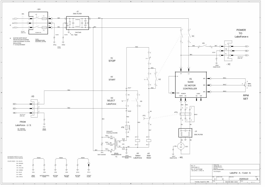
Spare Parts and Diagrams Table of contents Drawing Drawings Bearing Unit ...................................................................... 15180050B Water tap, assembly ......................................................... 14920065G Bottom cabinet, assembled ............................................... 15180060C Drawings Circuit diagram, LaboPol-1 ................................................. 15183100A Circuit diagram, LaboPol-2 ................................................. 15423105B Circuit diagram, LaboPol-5/-4-/6 ........................................ 15203110B Wiring diagram .................................................................. 15863450C
Some of the drawings may contain position numbers not used in connection with this manual.

LaboPol-1/-2/-4/-5/-6 Spare Parts and Diagrams
15
Drawing Pos. Spare Part Part No. 15180060 Bottom cabinet, assembled Rubber foot grey ø20x20 2GB00009 Sealing strip Grey 1.5x10 2IP10151 Splash ring ø250 15180101 Splash ring ø200 15180102 14920065 Water tap, assembly Water tap, assembled R5200050 15180050 Bearing Assembly LaboPol‐1,‐2,‐4,‐5,‐6 Disc shaft 15180200 Ball bearing, 6004‐2RSR 2BK00045 Wave spring wash., 28x34.5x0.5 2GF60020 Ball bearing, 6003‐2RS1, ø17xø35 2BK00040 Pulley ø230, machined 15180520 FEDER A 5x5x20 2ZF10520 Washer 10 A2 DIN9021A 2ZA20010 LaboPol‐1,‐2,‐5 Poly‐V belt XXX PJ4 (L=1041) 2JD31041 LaboPol‐4 Poly‐V belt 390 PJ4 (L=1016) 2JD30991 LaboPol‐6 POLY‐V‐REM 430 PJ4 (L=1092) 2JD31092

LaboPol-1/-2/-4/-5/-6 Spare Parts and Diagrams
16
Drawing Pos. Spare Part Part No. 15863450 LaboPol Series wiring Diagram LaboPol‐1 EPM Modul V2.0 LaboP‐1, progr. 15183902 LaboPol‐2 EPM Module V2.0 LP2, programmed 15423902 LaboPol‐4 EPM Module V2.1 LP4, programmed 15433902 LaboPol‐5 EPM Module V2.2 LP5, programmed 15203903 LaboPol‐6 EPM Module V2.0 LP6, programmed 15413902 LenzeFrq.conv.8200smd370W16kHz, A1 2PU81372 Switch 1804.1102 Black, S4 2SA60104 Connector 3‐POL. Female S678, X3 2XM00403 3‐POL Female, X2 2XN11032 Solid State Relay 10A 4‐30Vdc, K1 2KL81310 Mains socket w. fuse + switch, X1 2XN32107 Insul.cap, Mains connection, (X1) 2XN30001 Fuse holder, Mains socket, (X1) 2XN32901 4.00A T Fuse glass 6.3x32 250V, (X1) 2FU14200 Module holder. 3 elem. MHR‐3, S1,S2 2SA41603 Contact block 1 NC 1/2. MTO, S2 2SB10071 Contact block 1 NO 3/4. MTI, S1 2SB10072 Eco.push butt.head RTR (red), S2 2SA00415 Eco.push butt.head RTG (green), S1 2SA00410 Motor 71C4 250W 240 60CSA klix, M1 2ME51654 LaboPol‐4 only Motor 3x240/415‐60CSA M1 , 15240149 Rotary switch, machined, S32 15420077 Service Kits Service Kit LaboPol-1 15182999 Service Kit LaboPol-2 15422999 Service Kit LaboPol-4 15432999 Service Kit LaboPol-5 15202999 Service Kit LaboPol-6 15412999


01
02
04
02
001
011
021 031 06 07 09071
.mm 3 a no .ces 01 ni retaw toh °09 ni nethgiartS retaw dloc ni nwod delooc dna ,dor leets sselniats
.dor morf devomer si sti erofeb
.foorpretaW - 134 etitcoL.ediw mm3,0 xam mir eulg elbisiV
esaerg muucav hgiH
08
041
051
061
.ON .SOP TNUOMA .ON .WARD EMAN ETON01 1 pat rof esuoH 5010294102 2 278 RBN 27 87,1-28,01 gnir-O 51871OI204 1 278 RBN 27 6,1-01,6 gnir-O 50061OI206 1 92Ø ebut niaM 3110294107 1 noinu esoH 9010294108 1 278 RBN 27 5,1x5 GNIR-O 02051OI209 1 TROS 4-6MFN mm6 nolyn egnalS 53071UN2001 1 rehsaw lewoD 11102941011 1 01M tun laicepS 76001941021 1 7 NID 01x2ø irftsur tfits .lyC 01210SZ2031 1 92Ø eldnaH 21102941041 1 BZF B521 NID 21 evikS 52211CZ2051 1 eceip epiP 07001941061 1 cR 4-1 tun laicepS 94006621071 1 gnikcap htiw eldnips paT 66002941
09
06 07
0402 08
noisiveR etad .aerC noitpircsed noisiveRAG
50-21-3192.50.9002 )on gnorw( degnahc .on.soP
EPM/PP 60-50-42 EPM/GPF92.50.9002 VTJEPS
tinI .rppAtinI .warD etad .rppA
D
E
F
C
1 2 3 4
B
A
321 5
C
D
4 6 7 8
A
B
ylbmessa ,pat retaW 56002941
-8672 OSI/SD :ecnareloT:.taert ecafruS1:2 3A
:lairetaM :elacS
:DI
:tamroF
:veR:noitpircseD
dd-mm-yyyy dd-mm-yyyy
48 jevpurtsredePnegahnepoC/purellaB 0572-KD
kramneD008 006 44 54+:enohP408 006 44 54+ :xaF G
KmenoN


1
1
2
2
3
3
4
4
5
5
6
6
7
7
8
8
A A
B B
C C
D D
t>155C
PROTECTIONM1
MUST BE SHORT CIRCUITPROTECTED WITH EXTERNALFUSES ACCORDING TO LOCALREGULATIONS
F = 16Amp MAXIMUM
W1
M1
15183100
COLOR CODES:
WH = WHITE
BN = BROWN
GN = GREEN
YE = YELLOW
GY = GREY
RD = RED
PLATE
BOTTOM
PLATE
BOTTOM
FRAME PLATE
PLATE
YE/GN YE/GN
BL = BLUE
YE/GN
YE/GN
THERMAL
QS1
POWER ON
F1
F2
REAR
W2
3x1mm2
REAR
A2
A1
246
BK1
BK2
4
START
STOP
SELECT
TO
W3
BK = BLACK
POWER
THERMAL
PROTECTION
M2
REAR
2x6,3AMP
ALL WIRINGS 1², EXCEPT OTHERWISE MARKED.
1353
1
2
1 1a
2b
2
PLATE
PLATE
REARFRONT
X3
X2
X1
BK3
BK4
W4 5x1mm²BK5
BK2
3x1mm²
LABO POL-1
M
2 ~
MAINS SUPPLY:
100V/50Hz.
100V/60Hz.
220-240V/50Hz.
220-240V/60Hz.
110-120V/60Hz.
50µF
40µF
30µF
10µF
8µF
DEM/DEM
3x0,75mm²
BK9
BK11
BK10
C1
*
*
LaboForce-x
LaboForce-x
FROM LaboForce
SELECT
LaboForce
T1
T2
W4
W4
BK1BK2
BK4
BK5
W4YE/GN
L
N
PE
4
2
PE
1
3
2
A
Rev. A (04-09-97 FTH):F1, F2 changed from 5,0A to 6,3A
Friday, September 29, 1995
CIRCUIT DIAGRAM
STRUERS A/SVALHOEJSALLE 176DK-2610 ROEDOVREDENMARKPHONE:+45 3670 3500
1 1
A2Size CAGE CODE DWG NO Rev
SCALE Sheet of
K1
U1
U5
U6
K1
S3
XPE2
XPE3
XPE1
S3
XPE2
XPE3
XPE5 XPE6 XPE4
S2
S1
C1
L2
L1
PE
L2
L1
PE
PE
FT2
FT2

A
A
B
B
C
C
D
D
E
E
F
F
G
G
H
H
I
I
J
J
K
K
L
L
6 6
5 5
4 4
3 3
2 2
1 1
MUST BE SHORT CIRCUITPROTECTED WITH EXTERNALFUSES ACCORDING TO LOCALREGULATIONS
F = 16Amp MAXIMUM
-W1
YE/GN
-QS1
POWER ON
F1
F2
REAR
:6:4:2
BK1
BK2
THERMAL PROTECTIONM2 REAR
2x10AMP
:5:3:1PLATE
PLATE
-X3
3x1mm²
3x0,75mm²
LaboForce - 1 / 3:FROM
BK3
BK2
4
2
PE
1
3
2
*
3x1mm²
N
PE
REAR
LBK5
PLATE
-X2
TOYE/GN
LaboForce - 1 / 3:
POWER
YE/GN
-W2
W1
V1
U1 U2
V2
W2BK1
BK2
BK4
BOTTOM
PLATE FRAME
YE/GN
BOTTOM
COLOR CODES:
WH = WHITE
BN = BROWN
GN = GREEN
YE = YELLOW
GY = GREY
RD = RED
BU = BLUE
ALL WIRINGS 1² (AWG16), EXEPT OTHERWISE MARKED.
BK = BLACK
OG = ORANGE
VT = VIOLET
MAINS SUPPLY:
100V/50Hz.
100V/60Hz.
220-240V/50Hz.
220-240V/60Hz.
110-120V/60Hz. 60µF
16µF
-C1*
:2
:1
STOP
LOWSPEED
HIGHSPEED
:T1
- M1
:T2
A1
Low Speed
RD12A2
RD7
A2
High Speed
A1
LaboPol - 2:Rpm: 250 / 500
RD9
RD6
24V
20VA
230V
1,00
AT
SELECTLaboForce
RD2 RD3
RD
RD1
110V
0V
BK
BN
GR
X1:1
X1:2
X1:3
RD2
RD4
RD5
t>155C
PROTECTION
THERMAL
BK6
BK5
BK4
250 RPM 500 RPM
29 MAY 98 / DEM
14
13
RD6
RD6
RD10
RD11RD8
SelectLaboForce
BK5 BK3
BK3
BK1
BK2
RD4
X1:5
X1:4
RD
RD
-X1:6
-X1:7
BK1
BK2
MOUNTING
PLATE
YE/GN YE/GN
PLATE
FRONT
PLATE
BOTTOMREAR
PLATE
W2 7x1mm²
(BK)
(BN)
Rev.: A:Edition: XPE1 -> - 4, - 2 -> -1,XPE3 -> - 2, - 4 -> - 3.
- S1
- S3
- S2
- K3
Rev.:B: (DEM 08-03-02)Wiring to M1 modfy.C1 Change.
60µF
60µF
16µF
PHONE.: +45 3670 3500
B
STRUERS A/S
15423105Tuesday, March 12, 2002 1 1
A2
VALHOEJSALLE176DK-2610 ROEDOVREDENMARK
CIRCUIT DIAGRAM:
Size
Scale
CAGE Code DWG NO Rev
Sheetof
-S3
:4
-S2
:3
:4
:3
:53
:54
:6:4:2
:83
-K3
-K3
-K2
:5
:84
:3:1
:64
:54
-K2
:84
:53
:83
-K3
XPE2
:1
:2
-S3
:73
:74
-K3
XPE6
M3
/4/8pol
-M1
XPE10
-S1
-S2
XPE11
:1
:1a
:63
-S4:9
-K1
:5
XPE7
-C1
XPE9XPE5 XPE8
:S
-K2
:22
XPE4
:21
XPE3
-K2
:1
-K1
-K3
:22
:2
:21
:P
-T1TRANSFORMATOR
:2
-F3
-S4
:2b
-K2
XPE1REAR PLATE
L2
L1
PE
PE
FT2
FT2
PE
L1
L2
12
12
11
11
10
10
9
9
8
8
7
7
6
6
5
5
4
4
3
3
2
2
1
1
F F
E E
D D
C C
B B
A A
08.10.98 / DEM
THERMALPROTECTIONM2 REAR
PLATE
-X3
LaboForce - 1 / 3:FROM
1
3
2
START
STOP
A1
Start
A2
24V
20VA
230V
1,00
AT
SELECTLaboForce
110V
0V
BK
BN
GY
X1:1
X1:2
X1:3
Motor
14
13
SelectLaboForce
X1:5
X1:4
RD
RD
-X1:6
-X1:7
*
* MUST BE SHORT CIRCUITPROTECTED WITH EXTERNALFUSES ACCORDING TO LOCALREGULATIONSF = 16 Amp MAXIMUM
- W1
YE/GN
- QS1
POWER ON
F1
F2
REARPLATE
3x1mm²(AWG 18)
4
2
PE
3x0,75 mm²(AWG 18)
TO
246
YE/GN
SET
POWER
135
RPM
LaboForce-x
L2
DC MOTOR
POWER
L1
RUN
A1
CONTROLLERSP3
SP1
S1000A1
V+
LOGIC
SP2
A1A2/F2 InH
L
N
:3
:2
:1
6
5
2 4
31
2x4,7mH
- X2
- M1
YE/GNx
Cu - Tape
PLATE
F1/F2:
COLOR CODES:
WH = WHITE
BN = BROWN
GN = GREEN
YE = YELLOW
GY = GREY
RD = RED
BU = BLUE
BK = BLACK
BK WIRINGS AWG16 (1,3 mm²),RD WIRINGS 0,75mm² (AWG18).
BOTTOM FRONTPLATE
BOTTOM BOTTOM
YE/GN
PLATEREAR
YE/GN
MOTORCONTROLPLATE
YE/GN
PLATE FRAMEPLATE
LaboPol - 4, - 5 and - 6:
Wiring atT1Drawning 15423450
Rev.: A:Insert model - 6
MAXIMUM FUSES:EU/CSA/UL 10 Amp
Rev.: B: Text Change.- X2: N,-PE -> - X:PE, -N
PE
3x0,75 mm²(AWG 18)
Phone +45 3670 3500
B
Struers A/S
15203110Tuesday, August 01, 2000 1 1
A2
Valhoejs Alle 176DK 2610 RoedovreDenmark
Circuit Diagram
EK
Size
Scale
CAGE Code DWG NO Rev
Sheetof
RD3
RD1
RD2
RD5
BK2
BK1
RD4
RD6
BK7
BK10
BK6
BK11
BK13
BK12
BK9BK8
BUBU
BN BN
RD2
BK5
BK3
RD4
BK3
RD7
BK4
RD
BK4
D.E.M.
-S2
-S1
:4
:3
:96
- Z3
EMC FILTER
XPE8 XPE9
K2
- FT1
:95
K2
XPE11
XPE1
XPE7REAR PLATE
RP15K LIN
XPE4
:1
RV1
SIOV S14K230
:1a
XPE5
-S3
-FT1
:9
-K1
M
D/C
:5
XPE6
XPE10
:S
- Z2
XPE3
-K2-K1
:1
EMC FILTER
:P
:2
:2
-F3
-S3
-T1TRANSFORMATOR
:2b
XPE2REAR PLATE
XPE5MOTORCONTROL
PE
FT2
FT2
L1
PE
L2
L2
L1
PE

RP1 (on front)SET SPEED
1 32
FREQUENCY INVERTER
PE
X1
PLATE
3 1
1K0.25W
X2
1K
S2 (on front)STOP
24
S1 (on front)START
PE
UBK2N
+
STOP SIGNAL FROMEXTERNAL EQUIPMENT
MOUNTING
L
-
20 (+
12V
dc)
S4 (on back)Ext. Equipm.YES / NO
E.G.: THERMAL PROTECTION IN SAMPLE MOVER
X3
V
+temp.(120C)
W2L1
BK1
YE/GN
WN / L2
M1
E3
MOTOR
3-Phase motor240V / 60Hz
PE
9 E287 (C
omm
on)
E28
K12
E1K14
W3
A1
X10
X11
V
U
PE
W
W4
1 2 3 4 5 6 7 8 9 10 11 12
BK = BLACKCOLOR CODES:
FRONT
BU = BLUE
PLATE
YE/GN
RD = RED
YE/GN
GY = GREY
YE = YELLOW
ALL WIRINGS AWG-16, EXCEPT OTHERWISE MARKED.
GN = GREEN
BN = BROWN
WH = WHITE
200-240 V50-60 Hz
IN
200-240 V50-60 Hz
OUT
W5
S3 (on front)LOW / HIGHSPEED
W6
Strap Strap
M1 motor data:LaboPol-1: 4-poles, 250W (1/3 H.P.)LaboPol-2: 4-poles, 250W (1/3 H.P.)LaboPol-21: 4-poles, 250W (1/3 H.P.)LaboPol-25: 4-poles, 250W (1/3 H.P.)LaboPol-4: 8-poles, 80W (1/9 H.P.)LaboPol-5: 4-poles, 250W (1/3 H.P.)LaboPol-6: 250W (1/3 H.P.)
Plug-In Module(Machine setup)EPM
Only on:LaboPol-4LaboPol-5LaboPol-6LaboPol-25
Only on:LaboPol-2
R1
K1
OG = ORANGE
VT = VIOLETT
BK3
BK4
BK5
BK6
BK7
1 mm2
2x 0.75RD2
RD1
PLATEMOUNTING
PLATEMOUNTING
PLATEMOUNTING
PLATEMOUNTING
PLATEBOTTOM
PLATEBOTTOM
YE/GN
CHASSISALU.
PLATEBOTTOM
(MOTOR PLATE)
PLATEBOTTOM
YE/GN
FOUNDATIONDISK
LABOPOL-21/25 ONLY
YE/GN
YE/GN
YE/GN
0.75, BU8
3x 0.25 4x 0.5
8x 0.25
0.75, BU6
0.75, BU11
0.75, BU10
0.75, BU8
0.75, BU7
CFTH / FTH
BK1
BK2
BK3
YL/GN
Note:On LaboPol-21/25BK1 is connected to V andBK2 is connected to U
Note:
1 2A
1
3
2
1 21A 2B
1
2
PE
N
L
0.75, BU12
0.75, BU1
BN
WH
GN
BU BN BEBK
BE = BEIGE
BN WH GN RD BU YE GY
Rev.B: FTH 10-07-2003Wire identifications added.Rev.C: FTH 15-02-2008R1 resistor added in Power Switch X1
Power Entry Modulewith main power switch
F1 + F2
2x 4,0 ATR1
220k, 1W
PHONE: +45 3670 3500
STRUERS A/S
15863450Friday, February 15, 2008 1 1
A2
VALHOEJS ALLÈ 176DK-2610 ROEDOVREDENMARK
LABOPOL-SERIES, WIRING DIAGRAM
<Cage Code>Size
Scale
CAGE Code DWG NO Rev
Sheetof
XPE7 XPE10
XPE12
XPE8
XPE1
XPE2
XPE9XPE5
XPE4
XPE6
XPE3
XPE11


Pederstrupvej 84 DK-2750 Ballerup Denmark