Embed Size (px)
Citation preview

185306_Manual of Electrical Installationfor Pressure Probes_10-2014_ENG 1
Manual of Electrical Installationfor Pressure Probes
Code 85306 - Edition 10/2014
Index
1. General precautions page 22. Transmitters with digital output page 2 Standard installation page 2 Electrical connections (series MD / WD / KD / I / IJ) page 23. Transmitters with amplified analog output page 3 Standard installation page 3 Electrical connections (series TK / TPSA / TSA) page 3 Electrical connections (series TPFADA / TPFAS / TPHADA / TPSADA / TKDA) page 4 Electrical connections (series M / W / K / I) page 54. Transducers with non-amplified analog output page 8 Standard installation page 8 Electrical connections (series M / W / K / I) page 8 Electrical connections (series TPS) page 9 Electrical connections (series TPF / TPH) page 95. Protection for outdoor installations of analog sensors page 106. Standard reference page 11

2 85306_Manual of Electrical Installationfor Pressure Probes_10-2014_ENG2
1. General Precautions
The system must be used only in accordance with the required protection level.The sensor must be protected against accidental knocks and used in accordance with the instrument’s ambient characteristics and per-formance levels.The sensors must be powered with non-distributed networks and always at lengths of less than 30 mt.In case of outdoor installations, follow the instructions in paragraph 5.
2. Transmitters with digital output
Transducers: Series MD / WD / KD / I / IJ
Outputs: CANopen DP404
Installation notes- The transducer must be grounded (normally through the machine body or equipment it is installed on).- Use a shielded cable only. The braiding must be connected to the case of the 5-pin connector. On instrument/PLC side, we advise you
connect the braiding without power supply (0V GND).- To prevent interference, separate the power cables from the signal cables.
Seriess MD / WD / KD / I / IJCAN BUS DP404 digital output
Controller
Can Output
Power supply +
5-pin12345
Power supply -
Can H
Can L
n.c.
Electrical connections
MachinePress
EquipmentMD / WD
transducer
Ground
Braiding connected to connector case
PLC / Instrument
Rod / Pressure intake
Cable connectorBraiding connected to 0V GND
of PLC / InstrumentShielded cable
M12 DIN EN 50044 5-pin connector
Standard installation (recommended)
385306_Manual of Electrical Installationfor Pressure Probes_10-2014_ENG 3
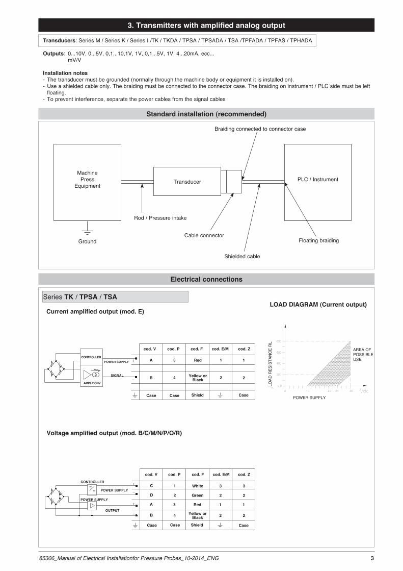
3. Transmitters with amplified analog output
Transducers: Series M / Series K / Series I /TK / TKDA / TPSA / TPSADA / TSA /TPFADA / TPFAS / TPHADA
Outputs: 0...10V, 0...5V, 0,1...10,1V, 1V, 0,1...5V, 1V, 4...20mA, ecc... mV/V
Installation notes- The transducer must be grounded (normally through the machine body or equipment it is installed on).- Use a shielded cable only. The braiding must be connected to the connector case. The braiding on instrument / PLC side must be left
floating. - To prevent interference, separate the power cables from the signal cables
Electrical connections
MachinePress
EquipmentTransducer
Ground
Braiding connected to connector case
PLC / Instrument
Rod / Pressure intake
Cable connectorFloating braiding
Shielded cable
Standard installation (recommended)
Series TK / TPSA / TSA
cod. V cod. P cod. F cod. Z
Case Case Shield
White
Green
Red
Yellow or Black
OUTPUT
POWER SUPPLY
CONTROLLER
POWER SUPPLY
cod. E/M
Case
3
2
1
2
3
2
1
2
1
2
3
4
C
D
A
B
SIGNAL
POWER SUPPLYCONTROLLER
AMPL/CONV
cod. V cod. P cod. F cod. E/M cod. Z
Red
Yellow or Black
ShieldCase Case
1
2
Case
A
B
1
2
3
4
Voltage amplified output (mod. B/C/M/N/P/Q/R)
Current amplified output (mod. E)LOAD DIAGRAM (Current output)
AREA OFPOSSIBLEUSE
POWER SUPPLY
LOAD
RES
ISTA
NC
E R
L

4 85306_Manual of Electrical Installationfor Pressure Probes_10-2014_ENG4
Series TPFADA / TPFAS / TPSADA / TKDA / TPHADA
Output amplified in voltage (mod. B/C/M/N/P/Q/R)
Output amplified in current (mod. E)
The cable sheathing is connected to the transducer body
The cable sheathing is connected to the transducer body
Male connector7 pole M16x0.75
Protection rating IP67
Shielded cable 6x0,25 - 1mProtection rating IP65
Shield
OrangeBlue
Red
BlackWhiteGreen
F - 6 pole cable
P - 7 pole connector
Male connector 6 pole bayonet
Protection rating IP66
V - 6 pole connector
Male connector4 pole
Protection rating IP67
Z - 4 poleconnector M12 x 1
4 Pin DIN Type AProtection rating IP65
4 Pin MicroDIN Tipo C-industrialProtection rating IP65
E – EN 175301-803 Type AM – EN 175301-803 Type C-ind
2 1
3 4
F - 4 pole cable
Shield Orange
Blue
Red
Black
Shielded cable 4x0,25 - 1m. (output E)Protection rating IP65
Note 1:On TPFAS series, Autozero and Calibration functions are available as options, see the relevant user manual downloadable on the website www.gefran.com
Note 2: The “Digital Autospan” function is activated by means of the “Calibration” contacts shown in the above diagram. For operation and complete functions, see the relevant user manual, downloadable on www.gefran.com.
LOAD DIAGRAM (Current output)
AREA OFPOSSIBLEUSE
Ω
LOAD
RES
ISTA
NC
E R
L
POWER SUPPLY
F - 2 pole cable
Shielded cable 2x0,25 - 2m. (output E)Protection rating IP65
Shield
Red
Yellow orBlack

585306_Manual of Electrical Installationfor Pressure Probes_10-2014_ENG 5
Series M / W / K
CURRENT OUTPUT
CURRENT OUTPUT (4...20mA, 2 wires)
6-pin 8-pin
A
C
B
D
E - F
B
A
D
C
E - F
G - H
n.c.
CONTROLLER
AMPL./CONV.
n.c.
n.c.
Power supply(10...30Vdc)
+
-Signal(4...20mA)
Calibration Shunt
Shield drain wire is tied to connector via cable clamp
6-pin 8-pin
A
C
B
D
E - F
B
A
D
C
E - F
G - H
n.c.
n.c.
n.c.
-
Power supply(10...30Vdc)
Signal(4...20mA)
Autozero
+
MAGNETICAUTOZERO
EXTERNALAUTOZERO
Series I
RELAY OUTPUT (6-8 pin connector)
Shield drain wire is tied to connector via cable clamp
Shield drain wire is tied to connector via cable clamp
The diagram shows the optimum ratio between load and power supply for transmitters with 4…20mA output.For correct function, use a combination of load resistance and voltage that falls within the two lines in the graph above.
0
100
200
300
400
500
600
700
800
10 11 12 13 14 15 16 17 18 19 20 21 22 23 24 25 26 27 28 29 30 31 32
Vcc (Volt)
R (o
hm
)
LOAD DIAGRAM

6 85306_Manual of Electrical Installationfor Pressure Probes_10-2014_ENG
ABCDEFGH
E +
S +
E -
S -
ConnectorPC06A-12-88 (SR) Connect the cable sheathing
to the side of the instrument
Power supply
SignalPower supply
Signal
R-Cal
No connection
8-pin connector Magnetic Autozero versionA = Excitation + (white)B = Signal + (red)C = Excitation - (green)D = Signal - (black)E = R-Cal (blue)F = R-Cal (brown)G = no connectionH = no connection
External Autozero versionA = Excitation + (white)B = Signal + (red)C = Excitation - (green)D = Signal - (black)E = Autozero (blue)F = Autozero (brown)G = no connectionH = no connection
(*) The Pin B of the connector must be connected to the common of the ± 15Vdc supply
VOLTAGE OUTPUT (H, L)Power supply -15..+15Vdc (*)
Series M - W - K
VOLTAGE OUTPUT (M, N, B, C)Supply 15..30Vdc 6-pin
C
D
A
B
E - F
CONTROLLER
AMPLIF.
Signal
Calibration Shunt
Segnale
Shield drain wire is tied to connector via cable clamp
+
+-
-
Supply
Supply
6-pin
C
D
A
B
E - F
Signal
Autozero
Signal
+
+-
-
Supply
Siupply
MAGNETICAUTOZERO
EXTERNALAUTOZERO
Series I
VOLTAGE OUTPUT (M, N, B, C)Supply 15..30Vdc

785306_Manual of Electrical Installationfor Pressure Probes_10-2014_ENG
6-pin connectorVPT07RA10-6PT2
(PT02A-10-6P)
8-pin connectorPC02E-12-8P
Bendix
8 pin connector (Binder) M16 DIN/EN45326
(09-0173-00-08)
Series I7
VOLTAGE OUTPUT
Shield drain wire is tied to connector via cable clamp
RELAY OUTPUT (6-8 pin connector)

8 85306_Manual of Electrical Installationfor Pressure Probes_10-2014_ENG8
4. Transducers with non-amplified analog output
Transducers: Series M / Series W / Series K / Series I / TPS / TPF / TPH
Output: mV/V
Installation notes- The transducer must be grounded (normally through the machine body or equipment it is installed on).- Use a shielded cable only. The braiding on connector side must be left floating. The braiding on instrument / PLC side must be con-
nected to the power supply GND.- To prevent interference, separate the power cables from the signal cables
Electrical connections
Standard installation (recommended)
Series M / W / K
MachinePress
Equipment
Ground
Floating braiding (not connected)
PLC / Instrument
Rod / Pressure intake
Cable connector
Shielded cable
mV/V OUTPUT
6-pin connectorVPT07RA10-6PT2
(PT02A-10-6P)
8-pin connectorPC02E-12-8P
Bendix
6-pin 8-pin
C
D
B
A
E - F
A
C
D
B
E - F
G - Hn.c.
Supply +
+
Signal
Calibration Shunt
Supply -
-Signal
Shield drain wire is tied to con-nector via cable clamp
R-Cal
Series I
mV/V OUTPUT

985306_Manual of Electrical Installationfor Pressure Probes_10-2014_ENG 9
mV/V output
Series TPS / TPF / TPH
Male connector09-0127-09-07Protection IP67
P - 7 pole connector
Male connector VPT02A10-6PT2Protection IP66
V - 6 pole connector
4 pin Male connectorserie 713
Protection IP67
Z - 4 pole maleconnector M12 x 1
4 Pin DIN Type AProtection IP65
4 Pin MicroDIN Tipo C-industrialProtection IP65
E – EN 175301-803 Type AM – EN 175301-803 Type C-ind
2 1
3 4
Shielded cable 6x0,25 - 1mProtection IP65
Shield
Orange
Blue
Red
Black
White
Green
F - 6 pole cable

10 85306_Manual of Electrical Installationfor Pressure Probes_10-2014_ENG10
5. Protection for outdoor installations of analog sensors
Pressure / Analog Melt voltage outputCAL signals if any do not require protection
J1
J1
J1
J1
PLC side +24Vdc
PLC side +IN
PLC side GND
PLC side Ground
D4
D1 D2
D3
J2
J2
J2
Transducer side +24Vdc
Transducer side +OUT
Transducer side GND
B72210-S-250-K01
B72210-S-250-K01
B72210-S-250-K01B72210-S-250-K01
PLC ground machine ground
1
1
1
1
1
1
1
Pressure / Analog Melt current outputCAL signals if any do not require protection
J1
J1
J1
PLC side +24Vdc
PLC side +IN
PLC side Ground
D1 D3
J2
J2
Transducer side +24Vdc
Transducer side +OUT
B72210-S-250-K01B72210-S-250-K01
PLC ground machine ground
1
1
1
1
1
D2
B72210-S-250-K01

1185306_Manual of Electrical Installationfor Pressure Probes_10-2014_ENG 11
6. Standard reference
Gefran products, described in this manual, are compliant to the European Directive 2004/108/CE.They are tested according to the standard EN 61326-1 “Electrical equipment for measurement, control and laboratory use - EMC requi-rements”, Part 1 “general requirements and EN 61326-2-3 “Electrical equipment for measurement, control and laboratory use - EMC requirements”, Part 2-3: Particular requirements - Test configuration, operational conditions and performance criteria for transducers with integrated or remote signal conditioning.
Electromagnetic Compatibility (EMC) requirements are classified in two types: Emission requirements, Immunity requirements
Emission requirementsFor class B equipment the limits, the measuring methods and the provisions given in CISPR11, EN 61000-3-2 and EN 61000-3-3 apply.Equipment classification and choice of respective limits shall be determined after taking into account the intended environment and emission requirement in the areas of use
Immunity requirementsThe immunity test requirements are given in table 1.The tests shall be conducted in accordance with the basic standards. The tests shall be carried out one at time.
a) Line to lineb) Line to groundc) Only in the case of long-distance linesd) Only in the case of lines > 3 mg) DC connections between parts of equipment/system which are not connected to a d.c. distribution network are treated as I/O signal/
control ports
Performance criterion ADuring testing, normal performance within the specification limits.
ExampleIf electronic equipment is required to work with high reliability, the EUT shall operate without any apparent degradation from the manu-facturer’s specification.
Performance criterion BDuring testing, temporary degradation, or loss of function or performance which is selfrecovering.
ExampleDuring testing, an analogue function value may deviate. After the test, the deviation vanishes.
Performance criterion CDuring testing, temporary degradation, or loss of function or performance which requires operator intervention or system reset occurs.
ExampleIn the case of an interruption in the mains longer than the specified buffer time, the power supply unit of the equipment is switched off. The switch-on may be automatic or carried out by the operator.
Copy of the conformity declaration is available for download on the Gefran web site www.gefran.com
Table 1 - Immunity test requirements for equipment intended for use in industrial locations
Port Phenomenon Basic Test value Performance Performance standard criteria criteria requested applied by Gefran
Enclosure Electrostatic discharge (ESD) EN 61000-4-2 4 kV / 8 kV contact/air B A
EM field EN 61000-4-3 10 V/m (80 MHz to 1 GHz) A A
3 V/m (1,4 GHz to 2 GHz)
1 V/m (2,0 GHz to 2,7 GHz)
Rated power frequency EN 61000-4-8 30 A/m A A (@ 400 A/m)
magnetic field
Power supply DC g) Burst EN 61000-4-4 2 kV (5/50 ns, 5 kHz) B A
Surge EN 61000-4-5 1 kV a) / 2 kV b) B B
Conducted RF EN 61000-4-6 3 V (150 kHz to 80 MHz) A A (@ 10V)
I/O signal/control Burst EN 61000-4-4 1 kV (5/50 ns, 5 kHz) d) B A
(including functional Surge EN 61000-4-5 1 kV b), c) B B
earth lines) Conducted RF EN 61000-4-6 3 V (10 kHz to 80 MHz) A A (@ 10V)