Embed Size (px)
Citation preview
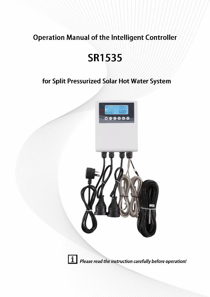

Manual of SR1535 intelligent controller
1
Contents
1. Safety information ................................................................................................................. 3
1.1 Installation and commissioning ............................................................................................ 3
1.2 About this manual ................................................................................................................... 3
1.3 Liability waiver ......................................................................................................................... 3
1.4 Important information ............................................................................................................. 3
1.5 Signal description ................................................................................................................... 4
1.6Button and HMI description ................................................................................................... 4
2. Overview .................................................................................................................................... 5
2.1 Technical data ......................................................................................................................... 5
2.2 Delivery list .............................................................................................................................. 5
3. Installation .................................................................................................................................. 6
3.1 Mounting controller ................................................................................................................. 6
3.2 Wiring connection ................................................................................................................... 6
4. System description (Standard solar system with 1 tank, 1 collector field)...................... 7
5. Function’s parameters and options ....................................................................................... 8
5.1 Overview of menu structure .................................................................................................. 8
5.2 Menu operation description .................................................................................................. 9
5.3 Value checking ........................................................................................................................ 9
5.4 Functions checking ................................................................................................................ 9
6. Functions operation and parameters setting (for user) ...................................................... 9
6.1 CLK Time setup ...................................................................................................................... 9
6.2 AH Afterheating/thermostat function.................................................................................. 10
7. Function operation and parameter setup (engineer) ........................................................ 13
7.1PWD Password ...................................................................................................................... 13
7.2 LOAD tank heating ............................................................................................................... 13
7.3 COL Collector function......................................................................................................... 15
7.4 COOL Cooling function ........................................................................................................ 20
7.5 MAN Manual operation ........................................................................................................ 21
7.6 BLPR Blocking protection ................................................................................................... 22
7.7 OTDI Thermal Disinfection function .................................................................................. 23
7.8 FS Flow rate monitoring and pump dry running protection ........................................... 24
7.9 UNIT C-F Switch ................................................................................................................... 25

Manual of SR1535 intelligent controller
2
7.10 BEEP Beeper fault warning .............................................................................................. 25
7.11 RET Reset ........................................................................................................................... 26
7.12 PASS Password setup ...................................................................................................... 26
7.13 M.H Manual heating ........................................................................................................... 27
7.14 Holiday function .................................................................................................................. 28
8. Protection function .................................................................................................................. 29
8.1 Memory function during power failure ............................................................................... 29
8.2 Screen protection ................................................................................................................. 29
8.3 Trouble checking................................................................................................................... 29
9. Quality Guarantee................................................................................................................... 30
10. Accessories ........................................................................................................................... 30

Manual of SR1535 intelligent controller
3
1. Safety information
1.1 Installation and commissioning
When laying wires, please ensure that no damage occurs to any of the constructional fire safety
measures presented in the building.
The controller must not be installed in rooms where easily inflammable gas mixtures are present
or may occur.
The permissible environmental conditions can’t be exceeded at the site of installation.
Before connecting the device, make sure that the energy supply matches the specifications that
controller requires.
All devices connected to the controller must conform to the technical specifications of the
controller.
All operations on an open controller are only to be conducted cleared from the power supply. All
safety regulations for working on the power supply are valid.
Connecting and /or all operations that require opening the collector (e.g. changing the fuse) are
only conducted by specialists.
1.2 About this manual
This manual describes the mounting, functions and operation of a solar controller used for a solar hot
water system, for mounting of other devices of a completed solar hot water system like solar collector,
pump station and storage, please is sure to observe the appropriate installation instructions provided
by each manufacturer. Mounting, wire connecting, commissioning and maintenance of this controller
may only be performed by the trained professional person; the professional person should be familiar
with this manual and follow the instructions contained herein.
1.3 Liability waiver
The manufacturer can’t monitor the compliance with these instructions or the circumstances and
methods used for installation, operation, utilization and maintenance of this controller. Improper
installation can cause damages to material and person. This is the reason why we do not take over
responsibility and liability for losses, damages or cost that might arise due to improper installation,
operation or wrong utilization and maintenance or that occurs in some connection with the
aforementioned. Moreover we do not take over liability for patent infringements or infringements –
occurring in connection with the use of this controller on the third parties rights. The manufacturer
preserves the right to put changes to product, technical data or installation and operation instructions
without prior notice. As soon as it becomes evident that safe operation is no longer possible (e.g.
visible damage). Please immediate take the device out of operation. Note: ensure that the device can’t
be accidentally placed into operation.
1.4 Important information
We have carefully checked the text and pictures of this manual and provided the best of our knowledge

Manual of SR1535 intelligent controller
4
and ideas, however inevitable errors maybe exist. Please note that we cannot guarantee that this
manual is given in the integrity of image and text, incorrect, incomplete and erroneous information and
the resulting damage we do not take responsibility.
1.5 Signal description
Safety indication: Safety instructions in the text are marked with a warning triangle. They
indicate measures which can lead to injury of person or safety risks.
Operation steps: small triangle “►”is used to indicate operation step.
Notes: Contains important information about operation or functions.
1.6Button and HMI description
Controller is operated with the 6 buttons on the right side of the screen
“ " holiday button
“M.H” button: manual heating
“SET” button: confirm / selection
“▲” up button: increase the value
“▼” down button: reduce the value
“ESC" button return/ exit : return to previous menu
Status description Code Lighting Blinking
Exceed the maximum temperature of storage SMX
Running of storage emergency shutdown function
Running of collector emergency shutdown function CEM
+
Collector Cooling OCCO
Tank Cooling OSTC

Manual of SR1535 intelligent controller
5
System Cooling OSYC
Start of anti-freezing function OCFR
Running of anti-freezing function OCFR
Collector minimum temperature OCMI Slow blink
2. Overview
2.1 Technical data
Inputs: 1 * PT1000 temperature sensor input
2 * NTC10K, B=3950 temperature sensor input
1*FRT flow meter port(Optional)
Outputs: 1 * Electromagnetic relay, maximum current 2A
1 * Electromagnetic relay, maximum current 10A
Functions: operating hours counter, tube collector function, thermostat function, adjustable
system parameters and optional functions (menu-driven), balance and diagnostics
Power supply: 100…240V ~(50…60Hz)
Rated impulse voltage: 2.5KV
Housing:Plastic ABS
Mounting:Wall mounting
Operation: 6 push buttons at the front cover
Protection type: IP43
Ambient temperature: 0 ... 40 °C
Dimensions: 153*180*40mm
2.2 Delivery list
1 * SR1535 controller
1 * accessory bag
1 * user manual
1 * PT1000 temperature sensor (φ6*50mm,cable length 20meters)
2 * NTC10K temperature sensor (φ6*50mm,cable length 3meters)
2* power jack for pump and electrical heater
1*10A power cord

Manual of SR1535 intelligent controller
6
3. Installation
Note: The unit must only be located in the dry interior rooms. Please separate routing of
sensor wires and mains wires. Make sure the controller as well as the system is not exposed to strong
electromagnetic fields.
3.1 Mounting controller
Follow the below steps to mount the controller on the wall.
Choose a suitable site
Make the position of hole(note that the positive
and negative)
Drill the fixing hole,insert the expansion screw.
Fix the hanging plate by using screw.
Press the control unit on the hanging plate.
Drill and insert lower wall plugs.
Fasten the housing to the wall with the lower
fastening screw and tighten.
Carry out the electrical wiring in accordance with the terminal allocation
Put the cover on the housing. Attach with the fastening screw.
3.2 Wiring connection
10A Power cord
Jack for pump connection
Jack for electrical heater
NTC10K Top sensor T3
NTC10K Button sensor T2
PT1000 Collector
temperature T1

Manual of SR1535 intelligent controller
7
Input ports
Main supply:10A 1.5m power cord.
T1: PT1000 temperature sensor with 20m cable, for measuring the temperature of collector and
thermal energy calculation.
T2 ~T3: NTC10K, B=3950 temperature sensor with 3m able, for measuring temperature of tank
and pipe.
FRT flow meter port : for flow meter connection (The FRT flow meter port not in the standard
configuration;flow meter should be purchased separately, detailed see annexed part)
Output ports
Output R1: Electromagnetic relay, connect a power jack with 0.5m cable.Max. Current: 1A
Output HR: Electromagnetic relays, designed for on/off control of afterheating/thermostat function, Max.
Current: 1500W.
Advice regarding the installation of temperature sensors:
Only original factory equipped Pt1000 temperature sensors are approved for using with the
controller, it is equipped with 20m cable and suitable for all weather conditions, the prior 1.5m
silicon cable is temperature resistant up to 280oC, the extension PVC cable is temperature
resistant up to 80oC connect the temperature sensors to the corresponding terminals with either
polarity.
Only original factory equipped NTC10K,B=3950 temperature sensors are approved for using with
tank and pipe, it is equipped with 3m PVC cable, and the cable is temperature resistant up to
80oC, connect the temperature sensors to the corresponding terminals with either polarity.
All sensor cables carry low voltage, and to avoid inductive effects, must not be laid close to 230
volt or 400 volt cables (minimum separation of 100mm).
If external inductive effects are existed, e.g. from heavy current cables, overhead train cables,
transformer substations, radio and television devices, amateur radio stations, microwave devices
etc., then the cables to the sensors must be adequately shielded.
Sensor cables may be extended to a maximum length of ca. 100 meter, when cable’s length is
up to 50m, and then 0.75mm2 cable should be used. When cable’s length is up to 100m, and
then 1.5mm2 cables should be used.
4. System description (Standard solar system with 1 tank, 1 collector field)
Description:
The controller calculates the temperature difference between collector sensor T1 and tank sensor T2. If the difference is larger than or identical to the adjusted switch-on temperature difference, the solar circulation pump (R1) will be switched on and the tank will be loaded until the switch-off temperature difference or the maximum tank temperature is reached.

Manual of SR1535 intelligent controller
8
Sensor Description Relay Description
T1 Temperature of collector R1 Solar circulation pump
T2 Temperature of tank base HR Afterheating/thermostat function
T3 Temperature of tank upper
5. Function’s parameters and options
5.1 Overview of menu structure

Manual of SR1535 intelligent controller
9
5.2 Menu operation description
Access main menu
►Press “SET” button to access main menu
►Press “▲/▼” to select menu
►Press “SET” button to enter the submenu
Access submenu
►After selecting main menu, then press “SET” button to access submenu
►Press “▲/▼” button to select submenu,
►Press “SET” button to enter the value adjust interface or selection function( select ON/OFF)
►Press “▲/▼” to adjust value
►Press “SET” to confirm the value you set
Note: Enter the menu adjustment interface, if you don’t press any button within 3 minutes, screen
will exit the adjustment and turn to main interface.
5.3 Value checking
At the normal operation mode, press “▲/▼” button, you can view the temperature of collector and tank,
controller running time, software version.
Note: enter the value check interface, if you don’t press any button within 1 minutes, screen will
exit the check interface and turn to main interface.
5.4 Functions checking
under standby status, press “SET” button for 3 seconds, then press “▲/▼” button to checkThermal
disinfection setting.
Note: Thermal disinfection functions can be displayed in controller only when the function is
activated, when it is running, its code blinks in time zone.
6. Functions operation and parameters setting (for user)
6.1 CLK Time setup
Menu structure
► Press “SET” button, select CLK menu
► Press “SET” button, hour “00” blinks on the display.
► Press “▲/▼” button to adjust hour
Manual of SR1535 intelligent controller
10
► Press “SET” button, minute time “00” blinks on the display
► Press “▲/▼” button to adjust minute
► Press “SET” or “ESC” button to save the set value
Note: In the case power to controller is switched-off, date and time will be remembered in
controller for 36 hours.
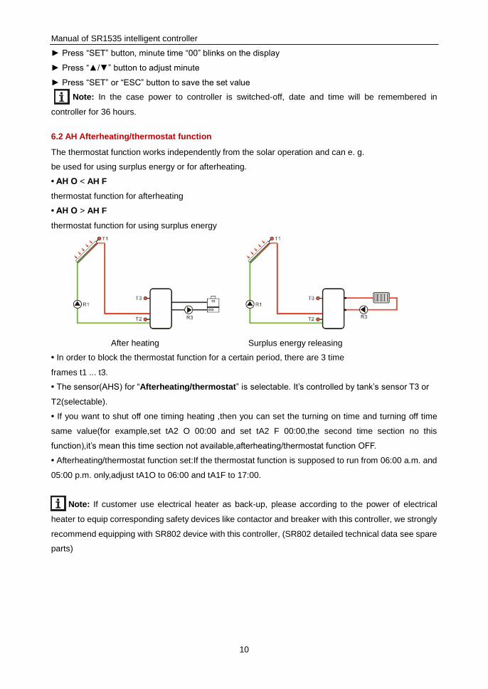
6.2 AH Afterheating/thermostat function
The thermostat function works independently from the solar operation and can e. g.
be used for using surplus energy or for afterheating.
• AH O < AH F
thermostat function for afterheating
• AH O > AH F
thermostat function for using surplus energy
After heating Surplus energy releasing
• In order to block the thermostat function for a certain period, there are 3 time
frames t1 ... t3.
• The sensor(AHS) for “Afterheating/thermostat” is selectable. It’s controlled by tank’s sensor T3 or
T2(selectable).
• If you want to shut off one timing heating ,then you can set the turning on time and turning off time
same value(for example,set tA2 O 00:00 and set tA2 F 00:00,the second time section no this
function),it’s mean this time section not available,afterheating/thermostat function OFF.
• Afterheating/thermostat function set:If the thermostat function is supposed to run from 06:00 a.m. and
05:00 p.m. only,adjust tA1O to 06:00 and tA1F to 17:00.
Note: If customer use electrical heater as back-up, please according to the power of electrical
heater to equip corresponding safety devices like contactor and breaker with this controller, we strongly
recommend equipping with SR802 device with this controller, (SR802 detailed technical data see spare
parts)
Manual of SR1535 intelligent controller
11
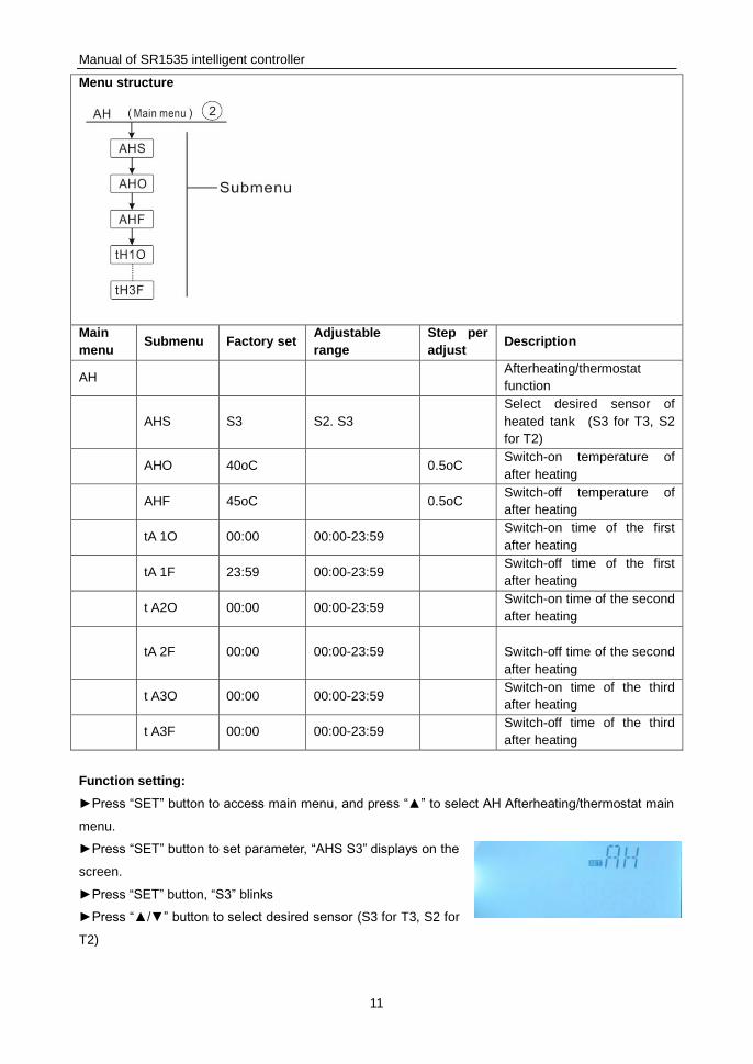
Menu structure
Main
menu Submenu Factory set
Adjustable
range
Step per
adjust Description
AH Afterheating/thermostat
function
AHS S3 S2. S3
Select desired sensor of
heated tank (S3 for T3, S2
for T2)
AHO 40oC 0.5oC Switch-on temperature of
after heating
AHF 45oC 0.5oC Switch-off temperature of
after heating
tA 1O 00:00 00:00-23:59 Switch-on time of the first
after heating
tA 1F 23:59 00:00-23:59 Switch-off time of the first
after heating
t A2O 00:00 00:00-23:59 Switch-on time of the second
after heating
tA 2F 00:00 00:00-23:59
Switch-off time of the second
after heating
t A3O 00:00 00:00-23:59 Switch-on time of the third
after heating
t A3F 00:00 00:00-23:59 Switch-off time of the third
after heating
Function setting:
►Press “SET” button to access main menu, and press “▲” to select AH Afterheating/thermostat main
menu.
►Press “SET” button to set parameter, “AHS S3” displays on the
screen.
►Press “SET” button, “S3” blinks
►Press “▲/▼” button to select desired sensor (S3 for T3, S2 for
T2)

Manual of SR1535 intelligent controller
12
►Press “SET” or “ESC” button to save the setting.
► Press “▲” button, “AHO 40oC” displays on the screen
►Press “SET” button, “40oC” blinks
►Press “▲/▼” button to adjust the switch-on temperature.
► Press “SET” or “ESC” button to save the setting.
► Press “▲” button, “AHF 45oC” displays on the screen
► Press “SET” button, hour time “45oC” blinks
► Press “▲/▼” button to adjust hour of the switch-off temperature.
► Press “SET” or “ESC” button to save the setting.
► Press “▲” button “tA1O 00:00” displays on the screen
► Press “SET” button, hour time “00” blinks
► Press “▲/▼” button to adjust hour of the switch-on time
► Press “SET” button, minute time “00” blinks
► Press “▲/▼” button to adjust minute of the switch-on time
► Press “SET” or “ESC” button to save the setting.
► Press “▲” button, “tA1F 23:59” displays on the screen
► Press “SET” button, hour time “23” blinks
► Press “▲/▼” button to adjust hour of the switch-off time
► Press “SET” button, minute time “59” blinks
► Press “▲/▼” button to adjust minute of the switch-off time
► Press “SET” or “ESC” button to save the setting.
► Press “▲” button to access the window of the switch-on time of the second afterheating/thermostat,
repeat above steps to set time for the second and third afterheating/thermostat.
If you want to shut of one time of afterheating/thermostat,you can set switch on and off at the same
value.(For example,the second time section no this function,then you can set tA2O 00:00 and tA2F
00:00)
When heating sign blinks on the screen, it indicates that after-heating function is activated.
Note:
The Sign" " represents After-heating
1. Within the preset time section, heating sign is lighted on the screen
2. Out of the preset time section, heating sign doesn’t display on the screen.
The Sign”AH“ represents Thermostat
1. Within the preset time section, heating sign “AH” is lighted on the screen ,if”AH” is blink,it’s
mean the Thermostat(cooling) is running.
2. Out of the preset time section, heating sign”AH”doesn’t display on the screen.

Manual of SR1535 intelligent controller
13
7. Function operation and parameter setup (engineer)
7.1PWD Password
Menu structure
Access main menu, select “PWD 0000” to enter password
► Press “SET” button, the left digital blinks, enter password, factory set is “0000”
►Press “▲/▼”, to enter the first digital
►Press “SET”, the second digital blinks
►Press “▲/▼” to enter the second digital
►Press” SET”, the third digital blinks
►Press”▲/▼” to enter the third digital
►Press “SET”, the forth digital blinks
►Press “▲/▼” to enter the forth digital
►Press “SET”, to access main menu
Through password set to limit the user to change some parameters, 4 digitals needed. Default is 0000
If no password is set, then just press “SET” five times to access main menu directly
7.2 LOAD tank heating
Function description:
△T control logic
The controller works as a standard temperature differential controller. If the temperature reaches or
exceeds the switch-on temperature difference (DTO), the pump switches on. When the temperature
difference reaches or falls below the adjusted switch-off temperature difference (DTF), the respective
relay switches off.
Note: The switch-on temperature difference must be 0.5 K higher than the switch-off
temperature difference. The set temperature difference must be at least 0.5 K higher than the
switch-on temperature difference.
SMX Maximum tank temperature protection set
If the tank temperature reaches the adjusted maximum temperature, the tank will no longer be loaded
in order to avoid damage caused by overheating. If the maximum tank temperature is exceeded,

Manual of SR1535 intelligent controller
14
sign is displayed on the screen.
The sensor for tank maximum limitation (SMAX) can be selected. The maximum limitation always
refers to the sensor selected (T2 or T3). The switch-on hysteresis (HYST) is selectable(Default is 2oC),
for example, when tank maximum temperature is set to 70oC, then at 68
oC, Maximum tank
temperature protection function is deactivated automatically.
Menu Structure
Main menu
Submenu Factory set
Adjustable range
Step per adjust
Description
LOAD Tank heating
DTO 6K 1-50K 0.5K Switch-on temperature difference of tank
heating
DTF 4K 0.5-49.5K 0.5K Switch-off temperature difference of tank
heating
SMX 70oC 4-95
oC 1
oC Maximum temperature of tank
SMAX S3 S2. S3 Sensor for Maximum temperature of tank
( S3 for T3, S2 for T2)
HYST 2K 0.1-10K 0.1K Hysteresis of maximum temperature of
tank
Setup the functions
► Select “LOAD” main menu
► Press “SET”, “DTO 6K” displays on the screen
► Press “SET”, “6K” blinks
► Press”▲/▼”, to adjust the switch-on temperature of the solar
circuit pump
► Press “SET” or “ESC” to save the setting
► Press “▲”, “DTF 4K” displays on the screen

Manual of SR1535 intelligent controller
15
► Press “SET”, “4K” blinks
► Press “▲/▼”, to adjust the switch-off temperature of solar circuit pump
► Press “SET” or “ESC” to save the setting
► Press “▲”, “SMX 70oC” displays on the screen
► Press “SET”, “70oC” blinks
► Press “▲/▼”, to adjust the maximum temperature of tank
► Press “SET” or “ESC” to save the setting
► Press “▲”, “SMAX S3” displays on the screen
► Press “SET”, “S3” blinks
► Press “▲/▼”, select the sensor for maximum temperature of tank (S3 for T3, S2 for T2)
► Press “SET” or “ESC” to save the setting
► Press “▲”, “HYST 2K” displays on the screen
► Press “SET”, “2K” blinks
► Press “▲/▼”, to adjust the hysteresis of tank maximum temperature
► Press “SET” or “ESC” to save the setting
7.3 COL Collector function
Function description
OCEM Collector emergency shutdown
When the collector temperature exceeds the adjusted collector emergency temperature,
Then solar pump (R1) switches off in order to protect the system components against overheating
(collector emergency shutdown). If the maximum collector temperature (OCEM) is exceeded,
sign is displayed.
Warning! Risk of injury! Risk of system damage by pressure surge! If water is used as the heat
transfer fluid in pressure systems, water will boil at 100 °C. Then do not set the collector limit
temperature higher than 95 °C.
OCCO Collector cooling
The collector cooling function keeps the collector temperature rising within the operating range by
heating the tank. If the tank temperature reaches 95°C the function will be switched off for safety
reasons.
When the tank temperature exceeds the adjusted maximum temperature of tank, then solar system is
switched off. If the collector temperature rises up to its adjusted maximum collector temperature, the
solar pump is switched on again until the collector temperature falls below the maximum collector
temperature. The tank temperature may then exceed its maximum temperature, but only up to 95°C
(emergency shutdown of the tank), and sign blinks on the screen, system stops.
If the collector cooling is active, blinks on the screen.

Manual of SR1535 intelligent controller
16
This function is only available when the system cooling function (OSYC) and the heat transfer function
(OHDP) are not activated.
OCMI Collector minimum temperature
The minimum collector temperature is the lowest temperature of collector, only when collector
temperature is higher than that temperature, solar pump (R1) just can be switched-on, if the collector
temperature falls below the adjusted minimum temperature, the function is activated, slow blinks
on the screen.
OCFR Collector antifreeze function
Collector antifreeze function activates the loading circuit between the collector and the tank when the
collector temperature falls below the adjusted temperature CFRO. This will protect the fluid against
freezing or coagulating. If collector temperature exceeds the switch-off temperature of collector
antifreeze function CFRF, the solar pump will be switched off again.
If collector antifreeze function is activated, sign slow blinks on the screen.
Note: Since this function uses the limited heat which is saved in the tank, so the antifreeze
function should be used in regions where ambient temperatures is around the freezing point
only for a few days.
OTCO Tube collector function
This function is used for improving the switch-on behavior in systems with non-ideal sensor positions (e.
g. with some tube collectors).
This function operates within an adjusted time section. It activates the collector circuit pump R1 for an
adjustable runtime between adjustable pauses in order to compensate for the delayed temperature
measurement.
If the runtime is set to more than 10s, the pump will run at 100% for the first 10s of the runtime. For the
remaining runtime, the pump will run at the adjusted minimum speed.
If the collector sensor is defective or the collector is blocked, this function will be switched off.

Manual of SR1535 intelligent controller
17
Menu structure
Main menu
Submenu 1
Submenu 2
Factory set
Adjustable range
Step per adjust
Description
COL Collector function
OCEM ON Collector emergency
shutdown function on/ff
CEM 130oC 80-200
oC 1
oC Temperature of collector
emergency
shutdown(hysteresis
10K)
OCCO OFF Collector cooling function
on/off
CMAX 110oC 70-160
oC 1
oC Temperature of collector
cooling ( hysteresis 5oC)
OCMI OFF Collector minimum
temperature function
on/off
CMIN 10oC 10-90
oC 1
oC Temperature of collector
minimum function
OCFR OFF Anti-freeze function on/off
CFRO 4oC -40-8
oC 0.5
oC Switch-on temperature of
anti-freeze function
CFRF 5oC -39-9
oC 0.5
oC Switch-off temperature of
anti-freeze function
OTCO Tube collector function
TCST 07:00 00:00-23:00 1min Start time of tube
collector function

Manual of SR1535 intelligent controller
18
TCEN 19:00 00:00-23:00 1min Stop time of tube
collector function
TCRU 30s 30-300s 1s Pump runtime during
tube collector function
TCIN 30min 5-60min 1min Pump stop time during
tube collector function
Function setting:
OCEM (Collector emergency shutdown function) setup
►Select “COL” function menu
►Press “SET”, “OCEM” displays on the screen
►Press “SET” again, “OCEM ON” displays on the screen
►Press “SET”, “ON” blinks on the screen
(If it is necessary to shut down this function, press “▲/▼” to deactivate it)
►Press “SET” or “ESC” to save the setting
►Press “▲”, “OCEM 130oC” displays on the screen
►Press “SET”, “130oC” blinks on the screen
►Press “▲/▼”, to activate or deactivate the collector emergency function
►Press “SET” or “ESC” to save the setting
►Press “ESC” to return to previous menu
OCCO (Collector cooling function) setup
►Press “▲”, “OCCO” displays on the screen
►Press “SET”, “OCEM OFF” displays on the screen
►Press “SET”, “OFF” blinks on the screen
►Press “▲/▼”, to activated this function, “OCEM ON” displays on the screen
►Press “▲”, “CMAX 110oC” displays on the screen
►Press “▲/▼”, to adjust the switch-on temperature of collector cooling function
►Press “SET” or “ESC” to save the setting
►Press “ESC” to return to previous menu
OCMI (Collector minimum temperature) setup
►Press “▲”, “OCMI” displays on the screen
►Press “SET”, “OCMI OFF” displays on the screen
►Press “SET”, “OFF” blinks on the screen
►Press “▲/▼”, to activate this function, “OCMI ON” displays on the screen
►Press “▲”, “OCMI 10oC” displays on the screen
►Press “▲/▼”, to adjust the minimum temperature of collector
►Press “SET” or “ESC” to save the setting

Manual of SR1535 intelligent controller
19
►Press “ESC” to return to previous menu
OCFR (Antifreeze function) setup
►Press “▲”, “OCFR” displays on the screen
►Press “SET”, “OCFR OFF” displays on the screen
►Press “SET”, “OFF” blinks on the screen
►Press “▲/▼”, to activate this function, “OCFR ON” displays on the screen
►Press “▲”, “CFRO 4oC” displays on the screen
►Press “SET”, “4oC” blinks on the screen
►Press “▲/▼”, to adjust the switch-on temperature of antifreeze function
►Press “SET” or “ESC” to save the setting
►Press “▲”, “CFRF 5oC” displays on the screen
►Press “SET”, “5oC” blinks on the screen
► Press “▲/▼”, to adjust the switch-off temperature of antifreeze function
►Press “SET” or “ESC” to save the setting
►Press “ESC” to return to previous menu
OTCO (Tube collector function) setup
►Press “▲”, “OTCO” displays on the screen
►Press “SET”, “OTCO OFF” displays on the screen
►Press “SET”, “OFF” blinks on the screen
►Press “▲/▼”, to activated this function, “OTCO ON” displays on the screen
►Press “▲”, “TCST 07:00” displays on the screen
►Press “SET”, “07” blinks
►Press “▲/▼”, to adjust hour
►Press “SET”, “00” blinks on the screen
►Press “▲/▼”, to adjust minute
►Press “SET” or “ESC” to save the setting
►Press “▲”, “TCEN 19:00” displays on the screen
►Press “SET”, “19” blinks
►Press “▲/▼” to adjust hour
►Press “SET”, “00” blinks
►Press “▲/▼”, to adjust minute
►Press “SET” or “ESC” to save the setting
►Press “▲”, “TCRU 30” displays on the screen
►Press “SET”, “30” blinks
►Press “▲/▼”, to adjust runtime
►Press “SET” or “ESC” to save the setting
►Press “▲”, “TCIN 30Min” displays on the screen

Manual of SR1535 intelligent controller
20
►Press “SET”, “30” blinks
►Press “▲/▼”, to adjust stop time
►Press “SET” or “ESC” to save the setting
►Press “ESC” to return to previous menu
7.4 COOL Cooling function
Function description:
There are 2 cooling functions can be activated for 2 different devices: system cooling, tank cooling.
OSYC System cooling
The system cooling function aims to keep the lifetime of a solar system for a longer time. The function
overrides the maximum tank temperature to provide thermal relief of the collector field and the heat
transfer fluid on hot days. If the tank temperature is higher than the adjusted maximum tank
temperature and the switch-on temperature difference DTCO is reached, the solar pump remains
running or will be switched on. Solar loading is continued until either the temperature difference falls
below the adjusted switch-off value DTCF or the collector emergency shutdown temperature OCEM is
reached.
Note: This function will only be available when the collector cooling function.
OSTC Tank cooling
When the tank cooling function is activated, the controller aims to cool down the tank during the night in
order to prepare it for solar loading on the following day. If the tank temperature exceeds the adjusted
maximum tank temperature SMAX, the collector temperature falls below the tank temperature and
down to the switch-on temperature difference DTCO of this cooling function, then system will be
activated in order to cool down the tank by releasing the energy through the collector.
If tank cooling function is activated, sign blinks on the screen
Note: if tank temperature reaches to 95 oC, all cooling functions will be locked.
Hysteresis switch on temperature difference is 5K.
Menu structure

Manual of SR1535 intelligent controller
21
Main menu
Submenu
1
Submenu 2
Factory set
Adjustable range
Step per adjust
Description
COOL Cooling function
OSYC OFF ON/OFF System cooling
function
OSTC OFF ON/OFF Tank cooling function
DTCO 20K 1-30K 0.5K Switch-on temperature
difference of cooling
function
DTCF 15K 0.5-29.5K 0.5K Switch-off temperature
difference of cooling
function
Function setting:
OSYC (system cooling function) setting
►Select “COOL” menu
►Press “SET”, “OSYC OFF” displays on the screen
►Press “SET”, “OFF” blinks on the screen
►Press “▲/▼”, to activate this function
►Press “SET” or “ESC” to save the setting
OSTC (Tank cooling function) setting
►Press “▲” button, “OSTC” displays on the screen
►Press “SET”, “OSTC OFF” displays on the screen
►Press “SET” button, “OFF” blinks
►Press “▲/▼” to activate this function
►Press “▲”, “DTCO 20K” displays on the screen
►Press “SET”, “20K” blinks
►Press “▲/▼”, to adjust the switch on temperature difference
►Press “SET” or “ESC” to save the setting
►Press “▲”, “DTCF 15K” displays on the screen
►Press “▲/▼”, to adjust the switch-off temperature difference
►Press “SET” or “ESC” to save the setting
►Press “ESC” to return to previous menu
7.5 MAN Manual operation
For control and service work, the operating mode of the relays can be manually adjusted. For this
purpose, select the adjustment menu MAN (for R1, HR) to set output “On/OFF” Manually.
Note: When manual mode is activated, sign blinks on the screen, controller runs for 15
minutes and then switch-off all output, control exits manual mode automatically.

Manual of SR1535 intelligent controller
22
Menu structure
Main Menu Submenu Factory set Adjustable range Description
MAN Manual mode
R1 OFF ON/OFF R1 on and off
HR OFF ON/OFF HR on and off
Function setup
►Press “▲”, “R1” displays on the screen
►Press “SET”, “R1 OFF” displays
►Press “SET”, “OFF” blinks
►Press “▲/▼”, to activate this function, “R1 ON” displays
►Press “SET” or “ESC” to save the setting
►Press “▲”, “HR” displays, repeat above steps to set the manual output of HR.
7.6 BLPR Blocking protection
Function description:
In order to protect the pumps against blocking after standstill, the controller is equipped with a blocking
protection function. This function switches on the relays one after another every day at 12:00 a.m and
pump runs for 10s at 100 % speed.
Menu structure
Main Menu Submenu Factory set Description
BLPR ON/OFF OFF
Function setting
►Press”▲”, “BLPR” displays on the screen
►Press “SET”, “BLPR OFF” displays
►Press “SET”, “OFF” blinks
►Press “▲/▼”, to activate this function, “BLPR ON” displays on the screen
►Press “SET” or “ESC” to save the setting

Manual of SR1535 intelligent controller
23
7.7 OTDI Thermal Disinfection function
Function description:
This function helps to prevent the spread of Legionella in DHW tanks by systematically activating the
after-heating.
For thermal disinfection, the temperature at the allocated sensor has to be monitored. During the
monitoring period PDIS, this protection ensures the disinfection temperature is continuously exceeded
the disinfection temperature TDIS for the entire disinfection period DDIS. Thermal disinfection can only
be completed when the disinfection temperature is exceeded for the duration of the disinfection period
without any interruption.
The monitoring period PDIS starts as soon as the temperature at the allocated sensor falls below the
disinfection temperature TDIS, once the monitoring period PDIS ends, disinfection period SDIS starts,
and the allocated reference relay activates the after-heating, when tank temperature exceeds the
disinfection temperature, disinfection phase DDIS starts and disinfection heating time countdowns,
countdown finishes, disinfection heating finishes.
Menu structure
Menu Submenu Factory set
Adjustable range
Step per adjust
Description
OTDI OFF ON/OFF Disinfection function
PDIS 7d 0-30d 1d Time section of disinfection monitoring
DDIS 10min 1-180 1min Heating time of disinfection
TDIS 70oC 0-90
oC 1
oC Temperature of disinfection
SDIS 18:00 00:00-21:00 1:00 Start time of disinfection
Function setting
►Press “▲”, “OTDI” displays on the screen
►Press “SET”, “OTDI OFF” display
►Press “SET”, “OFF” blinks
►Press “▲/▼”, to activate this function, “OTDI ON” displays
►Press “SET” or “ESC” to save the setting
►Press “▲”, “PDIS 7” displays

Manual of SR1535 intelligent controller
24
►Press “SET”, “7” blinks
►Press “▲/▼”, to adjust the days for disinfection monitoring,
►Press “SET” or “ESC” to save the setting
►Press “▲”, “DDIS 10Min” displays on the screen
►Press “SET”, “10” blinks
►Press “▲/▼”, to adjust the heating time of disinfection
►Press “SET” or “ESC” to save the setting
►Press “▲”, “TDIS 70oC” displays on the screen
►Press “SET”, “70oC” blinks
►Press “▲/▼”, to adjust the temperature of disinfection
►Press “SET” or “ESC” to save the setting
►Press “▲”, “SDIS 18:00” displays on the screen
►Press “SET”, “18” blinks
►Press “▲/▼”, to adjust the start time of the disinfection
►Press “SET” or “ESC” to save the setting
7.8 FS Flow rate monitoring and pump dry running protection
Function description:
In order to achieve this function, an extra digital flow meter FRT should be installed on the
return pipe of solar system, when solar pump R1 is triggered, the flow rate of return pipe is
monitored to ensure system runs normally.
If relay R1 is powered, if controller hasn’t got signal from digital flow meter within 30 seconds,
then solar pump R1 will be stopped, error message will appear, and sign will
blinks on the screen. By this function, it can avoid pump dry running.
Note: reasons for no flow rate in system:
No heat transfer liquid in system pipe due to pipe leakage.
Under this menu, the flow monitoring function can be activated and deactivated.
If open option of the flow monitoring function is activated, and then the sign will displays
on the screen, when circuit pump R1 is running, at the checking status you can check the
flow rate by press “▲/▼ ” button and check current flow rate L/M.
Note: digital flow meter FRT is not included in the delivery list, it is needed to buy
separately, see its specification in item 10.
Manual of SR1535 intelligent controller
25
Menu structure
Function setting
►Select FS menu
►Press “SET”, “FS OFF” displays
►Press “SET”, “OFF” blinks
►Press “▲/▼”, to activate this function,
►Press “SET” or “ESC” to save the setting
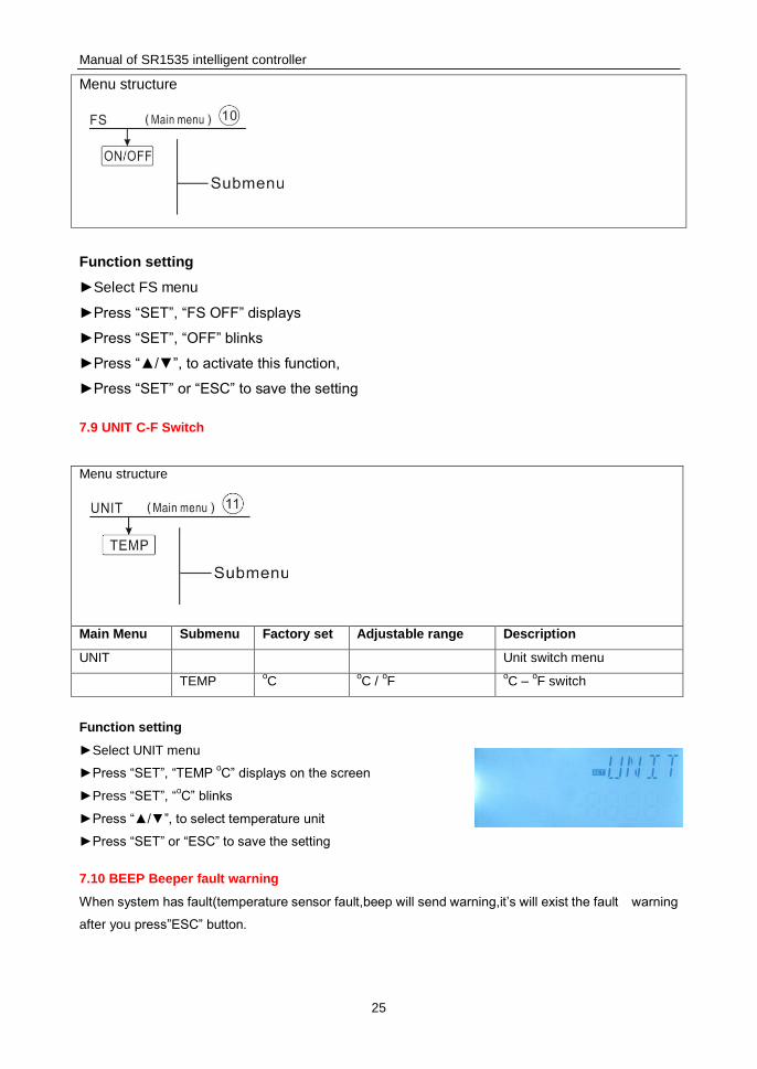
7.9 UNIT C-F Switch
Menu structure
Main Menu Submenu Factory set Adjustable range Description
UNIT Unit switch menu
TEMP oC
oC /
oF
oC –
oF switch
Function setting
►Select UNIT menu
►Press “SET”, “TEMP oC” displays on the screen
►Press “SET”, “oC” blinks
►Press “▲/▼”, to select temperature unit
►Press “SET” or “ESC” to save the setting
7.10 BEEP Beeper fault warning
When system has fault(temperature sensor fault,beep will send warning,it’s will exist the fault warning
after you press”ESC” button.

Manual of SR1535 intelligent controller
26
Menu structure
Main
Menu
submenu Factory
set
Description
BEEP ON/OFF OFF Beeper fault warning switch ON/OFF
BEEP(Beeper fault warning function) Setting
► Press “SET”, “BEEP” display on the screen.
► Press “SET”, “BEEP OFF” display on the screen.
► Press “SET”, “OFF” blink on the screen.
►Press“▲/▼”button, to switch on the function, “BEEP ON” display on the screen.
► Press “SET” or “ESC”to save the setting.
7.11 RET Reset
By means of the reset function, all adjustments can be reset to the factory settings.
Menu structure
Function setting
►Select RST menu
►Press “SET”, “RSTP” displays on the screen
►Press “SET”, “YES” blinks
►Press “SET” for 3 seconds, beeper sounds “di” 3 times, “YES”
lighting, and it indicates system is recovered to factory set.
►Press “ESC” return to the submenu
7.12 PASS Password setup
Function description:
This function helps to customers to set up new password.

Manual of SR1535 intelligent controller
27
Menu structure
Function Setting
Select the password setting, “PASS” menu
To access main menu PASS,
►Press “SET” button, “PWDC 0000” appears,
►Press “SET” button,the left digital blinks, ask for entering current password, factory set is “0000”
►Press “▲/▼”,button to enter the first digital
►Repress “SET” button, the second digital blinks
►Press “▲/▼”,button to enter the second digital
►Repress “SET” button, the third digital blinks
►Press “▲/▼”,button to enter the third digital
►Repress “SET” button, the fourth digital blinks
►Press “▲/▼”, button to enter the fourth digital
►Press “SET” button, “PWDG 0000” displays on the screen, ask for reentering the new password,
doing like above to reenter the new password, “OK” displays on the screen to indicate reentering
password successfully.
Note: If the password is forgot, it is impossible to recover, but you can recover the password to
factory set, then you can reedit a password like above descript steps, doing like following to
recover to factory set.
► Switch-off the power to controller
► Hold down “ESC” button
► Reconnect the power supply, when beeper sounds 3 di….., and then release “ESC” button,
Controller recovers to the factory set password (factory set possword is 0000),
7.13 M.H Manual heating
Function Description:
It is possible to trigger back-up heating manual with this controller to heat tank. When tank temperature
is lower than the set point of the switch-on temperature, manual heating function is in standby, when
you press the manual heating button, heating will start, and it works until tank temperature reaches to
the set point.
Activate/deactivate this function:

Manual of SR1535 intelligent controller
28
►Press “M.H” button for 3 seconds, temperature “60oC” blinks on the screen
►Press “▲/▼”, to adjust the desired temperature, adjustable range 10oC~80
oC, factory set is 60
oC
►Press “M.H” or “ESC” or waiting for 20 seconds to trigger the manual heating, then manual
sign displays on the screen, heating sign blinks the screen
►Press “M.H” again, switch-off manual heating.
Note: 1).Manual heating is not a continuous heating process, it is triggered manually, and when
the temperature reaches to the set point, the heating process is stopped. And manual heating function
is stopped automatically.
2).AHO>AHF: Thermostat function for using surplus energy, manual heating is not available.
7.14 Holiday function
The holiday function is used for operating the system when no water consumption is expected, e. g.
during a holiday absence. This function cools down the system in order to reduce the thermal
load.When bottom temperature of tank below down 35oC,the solar pump is deactivate.
Activate/deactivate this function:
►Press “ ” button for 3 seconds, “HDAY 05” displays on the screen
►Press “▲/▼”, to adjust holiday’s days, adjustable range 0-99 days
►Press “ ” for 3 seconds again, to adjust holiday’s days to 0,
►Press “ESC” to exit, holiday function is closed
Note:When you return from holiday, please deactivate this function in time.

Manual of SR1535 intelligent controller
29
8. Protection function
8.1 Memory function during power failure
When power of controller is failed, and when power is switched-on, controller will keep the parameters which set before power failure.
8.2 Screen protection
When no any press on button for 5 minutes, screen protection is activated automatically, and then LED
background lamp is switched-off. Through press any button to light LED lamp again.
8.3 Trouble checking
The built-in controller is a qualified product, which is conceived for years of continuous trouble-free
operation. If a problem occurs, the most of causes is from the peripheral components but no relation
with controller itself. The following description of some well-known problems should help the installer
and operator to isolate the problem, so that the system can be put into operation as quickly as possible
and to avoid unnecessary cost. Of course, not all possible problems can be listed here. However, most
of the normal problems encountered with the controller can be found in the list below, only return the
controller to seller when you are absolutely sure that none of the problems listed below is responsible
for the fault.
PT1000 resistance value
NTC 10K B=3950 resistance value

Manual of SR1535 intelligent controller
30
9. Quality Guarantee
Manufacturer provides following quality responsibilities to end-users: within the period of quality
responsibilities, manufacturer will exclude the failure caused by production and material selection. A
correct installation will not lead to failure. When a user takes incorrect handling way, incorrect
installation, improper or crude handling, and wrong connection of Warm water outflow upwards?
The quality warranty expires within 18 months after the date of purchasing the controller.
10. Accessories
Products name Specification Products picture
A01: High accurate
Pt1000 sensor for
collector
PT1000, Ф6*50mm
A02
High accurate sensor for
tank and pipe
NTC10K, B=3950, Ф6*50mm
A05
304 stainless steel
thermo well
304 stainless steel with thread 1/2’ OT,
Size: Ф8*200
A17:FRT digital flow
meter
Parameter: male thread 3/4
Power: 5-24V/DC
SR802
Unit for high power
electrical heater
Dimension:100mm*100mm*65mm
Power supply: AC180V ~ 264V, 50/60Hz
Suitable power: ≤ 4000W
Available ambient temperature: -10 ~ 50oC
Waterproof grade: IP43

Manual of SR1535 intelligent controller
31
SR802 connection diagram
Note: Switch-off power, and perform by profession installer.